mountaineer - coal combustion residual (ccr) site ... · runoff to that which falls directly on the...
TRANSCRIPT


Report
Mountaineer Bottom Ash Complex Report
Lockheed Martin Contractor for the USEPA December 2009

5851/44642
Report
Mountaineer Bottom Ash Complex
Assessment Report
Lockheed Martin Contractor for the USEPA
Robert R. Bowers, P.E.
Vice President
Gary B. Emmanuel, P.E.
Project Manager
December 2009
512 East Township Line Road Two Valley Square, Suite 120
Blue Bell, Pennsylvania 19422

Dam Safety Assessment Report – Mountaineer Bottom Ash Complex
Final: December 9, 2009 I:\Lockheed-Mar-Fs.5851\44642.Coal-Ash-Impoun\Docs\Reports\Mountaineer\Final\word\Bottom Ash_Rpt (Final).doc
i
TABLE OF CONTENTS 1. Introduction .................................................................................................................................. 1
1.1. General ................................................................................................................................... 1 1.2. Project Purpose and Scope ..................................................................................................... 1
2. Project/Facility Description ......................................................................................................... 3 2.1. Management Unit Identification ............................................................................................. 3 2.2. Hazard Potential ..................................................................................................................... 3 2.3. Impounding Structure Details ................................................................................................. 3
2.3.1. Embankment Configuration ........................................................................................... 4 2.3.2. Type of Materials Impounded ........................................................................................ 4 2.3.3. Stormwater Inflows ........................................................................................................ 4 2.3.4. Outlet Works .................................................................................................................. 4 2.3.5. Instrumentation ............................................................................................................... 5
3. Records Review ............................................................................................................................ 6 3.1. Design Documents .................................................................................................................. 7
3.1.1. Stability Analyses ........................................................................................................... 7 3.1.2. Modifications since Initial Construction ........................................................................ 7 3.1.3. Monitoring Instrumentation ............................................................................................ 8
3.2. Previous Inspections ............................................................................................................... 8 3.3. Facility Operator Interviews ................................................................................................... 8 3.4. Site Geology Summary ........................................................................................................... 9
4. Visual Inspection ........................................................................................................................ 10 4.1. Overview .............................................................................................................................. 10 4.2. Findings ................................................................................................................................ 10
5. Conclusions ................................................................................................................................. 11 6. Recommendations ...................................................................................................................... 12
6.1. Immediate/Urgent Repair Recommendations ...................................................................... 12 6.2. Long Term Improvements .................................................................................................... 12 6.3. Monitoring and Future Inspection Recommendations ......................................................... 12 6.4. Time Frame for completion of Repairs/Improvements ........................................................ 12 6.5 Certification Statement ......................................................................................................... 13

Dam Safety Assessment Report – Mountaineer Bottom Ash Complex
Final: December 9, 2009 I:\Lockheed-Mar-Fs.5851\44642.Coal-Ash-Impoun\Docs\Reports\Mountaineer\Final\word\Bottom Ash_Rpt (Final).doc
ii
Figures Figure 1 Site Location Map Figure 2 Site Layout Map Figure 3 Bottom Ash Complex – Plan Diagram Appendices Appendix A EPA Inspection Checklist Appendix B Photographic Log

Dam Safety Assessment Report – Mountaineer Bottom Ash Complex
Final: December 9, 2009 I:\Lockheed-Mar-Fs.5851\44642.Coal-Ash-Impoun\Docs\Reports\Mountaineer\Final\word\Bottom Ash_Rpt (Final).doc
1
1. Introduction
1.1. General
In response to the coal combustion waste (CCW) impoundment failure at the TVA/Kingston coal-fired electric generating station in December of 2008, the Environmental Protection Agency has initiated a nationwide program of structural integrity and safety assessments of CCW impoundments or “management units”. A CCW management unit is defined as a surface impoundment or similar diked or bermed management unit or management units designated as landfills that receive liquid-borne material and are used for the storage or disposal of residuals or by-products from the combustion of coal, including, but not limited to, fly ash, bottom ash, boiler slag, or flue gas emission control residuals. Management units also include inactive impoundments that have not been formally closed in compliance with applicable federal or state closure/reclamation regulations. The administration of this program is being supported by Lockheed Martin, who has authorized O’Brien & Gere to provide actual site specific impoundment assessments at selected facilities. This project is being conducted in accordance with the terms of Purchase Order No. 710051854, dated May 29, 2009, as amended on September 23, 2009.
1.2. Project Purpose and Scope
As stated in the Request for Proposal (RFP), the purpose of this work is to provide Dam Safety Assessments of CCW management units, including the following:
Identify conditions that may adversely affect the structural stability and functionality of a management unit and its appurtenant structures
Note the extent of deterioration, status of maintenance, and/or need for immediate repair Evaluate conformity with current design and construction practices Determine the hazard potential classification for units not currently classified by the
management unit owner or by state or federal agencies O’Brien & Gere’s scope of services for this project includes performing a site specific dam safety assessment of select CCW management units at the subject facility. Specifically, the scope includes the following tasks:
Perform a review of pertinent records (prior inspections, engineering reports, drawings, etc.) made available at the time of the site visit to review previously documented conditions and safety issues and gain an understanding of the original design and modifications of the facility.
Perform a site visit and visual inspection of each CCW management unit and complete the visual inspection checklist to document conditions observed.
Perform an evaluation of the adequacy of the outlet works, structural stability, quality and adequacy of the management unit’s inspection, maintenance, and operations procedures.
Identify critical infrastructure within 5 miles downgradient of management units.

Dam Safety Assessment Report – Mountaineer Bottom Ash Complex
Final: December 9, 2009 I:\Lockheed-Mar-Fs.5851\44642.Coal-Ash-Impoun\Docs\Reports\Mountaineer\Final\word\Bottom Ash_Rpt (Final).doc
2
Evaluate the risks and effects of potential overtopping and evaluate effects of flood loading on the management units.
Immediate notification of conditions requiring emergency or urgent corrective action.
Identify environmental permits issued for the management units
Identify leaks, spills, or releases of any kind from the management units within the last 5 years.
Prepare a report summarizing the findings of the assessment, conclusions regarding the safety and structural integrity, recommendations for maintenance and corrective action, and other action items as appropriate.
This report addresses the above issues for the Bottom Ash Complex management unit at Mountaineer Power Plant owned and operated by Appalachian Power Company (APC). APC is a subsidiary of American Electric Power Company (AEP). As such, AEP regularly provides engineering assistance to the APC Mountaineer Power Plant.

Dam Safety Assessment Report – Mountaineer Bottom Ash Complex
Final: December 9, 2009 I:\Lockheed-Mar-Fs.5851\44642.Coal-Ash-Impoun\Docs\Reports\Mountaineer\Final\word\Bottom Ash_Rpt (Final).doc
3
2. Project/Facility Description
The Mountaineer Power Plant is located near the City of New Haven, Mason County, West Virginia. It is owned and operated by APC. The facility operates one surface impoundment for storing CCW called the Bottom Ash Complex. The safety assessment summarized in this report details the September 2009 inspection of the Bottom Ash Complex. A site location map is provided as Figure 1.
2.1. Management Unit Identification
For the purposes of this report, the impoundment will be referred to as the Bottom Ash Complex. The Bottom Ash Complex carries the following identification numbers:
West Virginia Department of Environmental Protection (WVDEP) state dam identification number #05307
National Inventory of Dams #WV05307 A site layout map highlighting the location of the Bottom Ash Complex is provided as Figure 2. Please note the direction of plant north as commonly used by plant personnel. Plant north is referenced for convenience when describing the Bottom Ash Complex features and is not true north. Plant north will be used for compass reference of locations within this report.
2.2. Hazard Potential
The definitions for the four hazard potentials (less than low, low, significant and high) are included in the US EPA CCW checklist found in Appendix A. Based on the checklist definitions and as a result of this assessment, the hazard potential rating assigned to the Bottom Ash Complex is SIGNIFICANT. This rating was identified because failure of the embankments could result in environmental and economic damage. Potential environmental damage could include a release of ash slurry directly to Little Broad Run, a tributary of the Ohio River. Potential economic damage could include damage to the state highway and railway located along the east embankment. For reference, it should be noted that in a 2009 WVDEP inspection the Bottom Ash Complex has been assigned a “2” hazard class. This WVDEP hazard class is most closely equivalent to US EPA’s SIGNIFICANT Hazard Potential Classification.
2.3. Impounding Structure Details
The following sections summarize the structural components and basic operations of the Bottom Ash Complex. A diagram of the Bottom Ash Complex and its relevant features is provided as Figure 3. Additionally, photos taken during the visual inspection are incorporated in a Photographic Log provided as Appendix B.
Dam Safety Assessment Report – Mountaineer Bottom Ash Complex
Final: December 9, 2009 I:\Lockheed-Mar-Fs.5851\44642.Coal-Ash-Impoun\Docs\Reports\Mountaineer\Final\word\Bottom Ash_Rpt (Final).doc
4
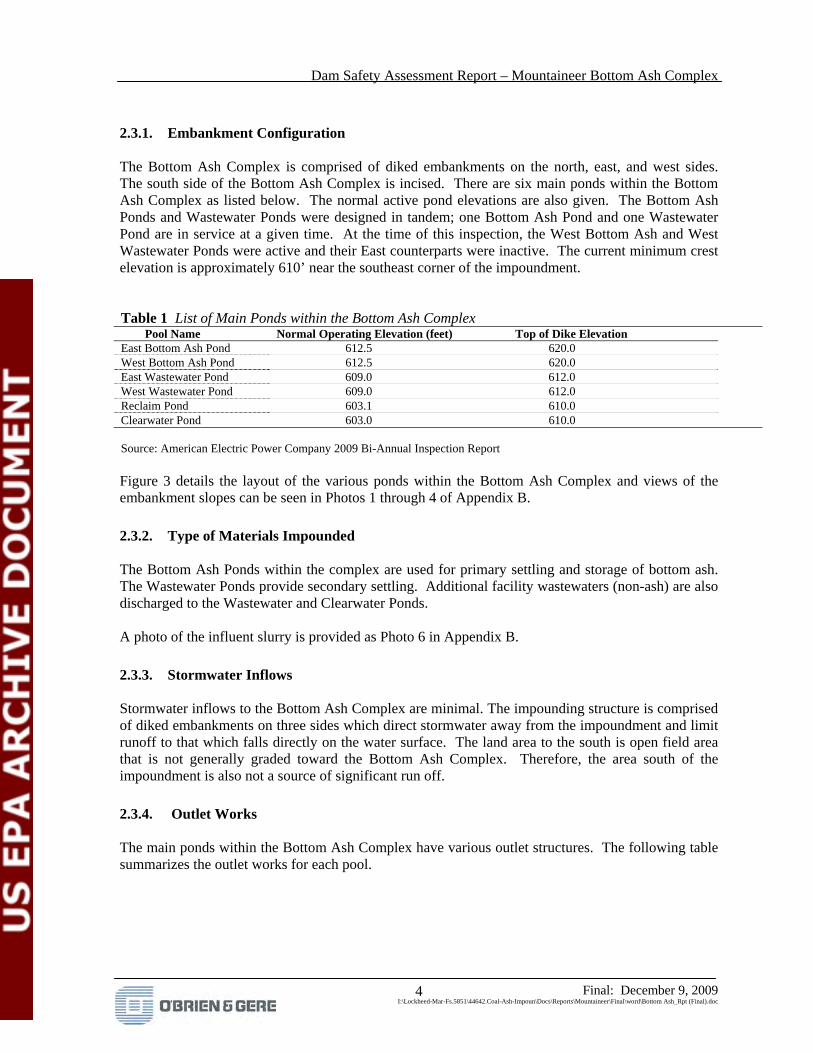
2.3.1. Embankment Configuration The Bottom Ash Complex is comprised of diked embankments on the north, east, and west sides. The south side of the Bottom Ash Complex is incised. There are six main ponds within the Bottom Ash Complex as listed below. The normal active pond elevations are also given. The Bottom Ash Ponds and Wastewater Ponds were designed in tandem; one Bottom Ash Pond and one Wastewater Pond are in service at a given time. At the time of this inspection, the West Bottom Ash and West Wastewater Ponds were active and their East counterparts were inactive. The current minimum crest elevation is approximately 610’ near the southeast corner of the impoundment. Table 1 List of Main Ponds within the Bottom Ash Complex Pool Name Normal Operating Elevation (feet) Top of Dike Elevation East Bottom Ash Pond 612.5 620.0 West Bottom Ash Pond 612.5 620.0 East Wastewater Pond 609.0 612.0 West Wastewater Pond 609.0 612.0 Reclaim Pond 603.1 610.0 Clearwater Pond 603.0 610.0 Source: American Electric Power Company 2009 Bi-Annual Inspection Report Figure 3 details the layout of the various ponds within the Bottom Ash Complex and views of the embankment slopes can be seen in Photos 1 through 4 of Appendix B.
2.3.2. Type of Materials Impounded The Bottom Ash Ponds within the complex are used for primary settling and storage of bottom ash. The Wastewater Ponds provide secondary settling. Additional facility wastewaters (non-ash) are also discharged to the Wastewater and Clearwater Ponds. A photo of the influent slurry is provided as Photo 6 in Appendix B.
2.3.3. Stormwater Inflows Stormwater inflows to the Bottom Ash Complex are minimal. The impounding structure is comprised of diked embankments on three sides which direct stormwater away from the impoundment and limit runoff to that which falls directly on the water surface. The land area to the south is open field area that is not generally graded toward the Bottom Ash Complex. Therefore, the area south of the impoundment is also not a source of significant run off.
2.3.4. Outlet Works The main ponds within the Bottom Ash Complex have various outlet structures. The following table summarizes the outlet works for each pool.

Dam Safety Assessment Report – Mountaineer Bottom Ash Complex
Final: December 9, 2009 I:\Lockheed-Mar-Fs.5851\44642.Coal-Ash-Impoun\Docs\Reports\Mountaineer\Final\word\Bottom Ash_Rpt (Final).doc
5
Table 2 Summary of Inlet and Outlet Works Pond Outlet Controlling Dimensions Notes
East Bottom Ash Pond 3-Sided Concrete Weir
~3’ width, fixed at elevation 612.0’
At time of inspection only one side of the weir was accepting flow while the other two gates were closed. A wooden surface skimming structure is constructed around the weir box.
West Bottom Ash Pond 3-Sided Concrete Weir
~3’ width, fixed at elevation 612.0’
At time of inspection West Bottom Ash Pond was inactive
East Wastewater Pond Long concrete weir channel
~230’ long, fixed at elevation 609.0’
At time of inspection West Wastewater Pond was inactive
West Wastewater Pond Long concrete weir channel
~230’ long, fixed at elevation 609.0’
2’wide x 2’ high concrete channel conveys weir discharge to outlet.
Reclaim Pond Inverted Pipe Elbow
~30” diameter None
Clearwater Pond Long concrete weir channel
~180’ long, fixed at elevation 603.0’
Approximately 30 to 50% of the weir length is raised and accepts no flow. A wooden surface skimming structure is constructed around the weir box. The weir discharges to 30” pipe via a concrete junction chamber. The 30” pipe transitions into a 42” pipe near the outlet at the Ohio River.
Source: O’Brien & Gere The photo log in Appendix B provides views of the various weir structures.
2.3.5. Instrumentation The Bottom Ash Complex has instrumentation to monitor flow discharged from the impoundment and three piezometers to monitor phreatic water levels within the north portion of the east embankment. A flow meter is located near the Clearwater Pond outlet. Facility personnel reported that totalized flow is recorded by a facility data logging system. The water level in the three piezometers is measured and recorded monthly by plant personnel.

Dam Safety Assessment Report – Mountaineer Bottom Ash Complex
Final: December 9, 2009 I:\Lockheed-Mar-Fs.5851\44642.Coal-Ash-Impoun\Docs\Reports\Mountaineer\Final\word\Bottom Ash_Rpt (Final).doc
6
3. Records Review
At the time of the site visit, APC provided historical Bottom Ash Complex documents for review. The following table summarizes reviewed documentation. Table 3 Summary of Bottom Ash Complex Documents Reviewed
Document Dates By Description
Design Drawings 1977 American Electric Power Company
Various plans and sections for the construction of the original impoundment and inlet/outlet works
Correspondence 1976 - 1977 Casagrande Consultants
Various geotechnical findings/recommendations prior to construction of the Bottom Ash Complex
Geotechnical Report 1977 Casagrande Consultants
Geotechnical investigation prior to construction of the Bottom Ash Complex
Dam Safety Report 1985 Woodward Clyde Consultants
Report documenting a dam safety inspection
Engineering Report 2006 Shaw – Stone & Webster
Engineering report detailing modifications to the north and west embankments to accommodate the construction of the gypsum conveyor. Includes WVDEP application, slope stability analysis, design drawings and specifications.
Construction Testing/Inspection Summaries 2006 H.C. Nutting
Engineering reports documenting geotechnical testing/inspection during the construction of the gypsum conveyor along the north and west embankments
Bi-Annual Inspection Reports 2007, 2009 American Electric Power Company
Annual inspection reports documenting inspection completed by corporate engineering staff.
Dam Safety Maintenance Plan & Approval 2007 - 2008 American Electric
Power & WVDEP Impoundment maintenance plan submitted by AEP to WVDEP and approval
WVDEP Order DS2009-0003 2009 WVDEP Order from WVDEP to AEP to provide/update current impoundment records of inspections, calculations, etc.
Dam and Dike Inspection Report 2009 H.C. Nutting Report documenting a dam safety
inspection in response to the WVDEP order
Engineering Report 2009 H.C. Nutting
Engineering report documenting soil borings, piezometer installation, and slope stability analysis completed in response to the WVDEP order
Piezometer Data & Sketch 2009 American Electric Power Company
Data and sketch completed by AEP to document early findings from recently installed piezometers
Site NPDES Permit 2009 WVDEP NPDES Permit #WV0048500 detailing allowable discharge parameters from the Bottom Ash Complex
Monthly/Quarterly Inspection Logs 2006 - 2009 Appalachian Power
Company
Recent monthly/quarterly inspection checklists completed by Mountaineer personnel
Source: O’Brien & Gere

Dam Safety Assessment Report – Mountaineer Bottom Ash Complex
Final: December 9, 2009 I:\Lockheed-Mar-Fs.5851\44642.Coal-Ash-Impoun\Docs\Reports\Mountaineer\Final\word\Bottom Ash_Rpt (Final).doc
7
3.1. Design Documents
3.1.1. Stability Analyses The original design of the dikes for the Mountaineer Bottom Ash Complex resulted from analyses and recommendations made on behalf of AEP by Casagrande Consultants in April 1977. Casagrande Consultants performed a sliding wedge analysis based on an assumed dike configuration with 2.5H:1V side slopes and soil characteristics derived from subsurface investigations. Factors of safety against a sliding failure within clay foundation soils were calculated to be 3.5 and 3.2 for normal/static and earthquake conditions respectively. The dikes were subsequently constructed with 3H:1V side slopes, which would increase these factors of safety. The stability of the north and west embankments were re-examined in 2006 to support an application for dam safety certification in connection with proposed modifications to the outboard slopes of those dikes to accommodate proposed gypsum conveyors. Stone & Webster, Inc. performed a two-dimensional slope stability analysis for two locations on the north embankment and one on the west embankment using the proposed embankment conditions following construction of the conveyors. The calculated Factors of Safety against sliding failure exceed the minimums required for steady state and earthquake loading conditions. In response to an order from the West Virginia Department of Environmental Protection, H.C. Nutting was engaged to perform an investigation of the slope stability of the east dike. A field exploration was performed which included six borings and the installation of three observation wells. Two-dimensional slope stability analyses were performed for two cross sections of the east dike of the Bottom Ash Pond and one cross section of the east dike of the clear pond using the results of the field investigation. The resulting factors of safety meet the minimums required for long-term (steady state) and earthquake loadings. Plant personnel are continuing to monitor the water level in the three observation wells on a periodic basis.
3.1.2. Modifications since Initial Construction The original dikes were constructed of soil borrowed from the site. In 2006, the north and west embankments were modified to accommodate a gypsum conveyor system. The following is a summary of the 2006 modifications.
Additional fill was placed along the length of the downstream side of the north embankment to accommodate the conveyor and an access road
Additional fill was placed at the toe of the northwest corner of the Bottom Ash Complex to accommodate a transfer house
Approximately 1300’ linear feet of the downstream side of the west embankment was cut up to four feet deep and up to twenty feet up the slope to accommodate the conveyor and access road. During construction of the conveyor, the cut areas were reinforced using geotextile, compacted soil and rip rap.

Dam Safety Assessment Report – Mountaineer Bottom Ash Complex
Final: December 9, 2009 I:\Lockheed-Mar-Fs.5851\44642.Coal-Ash-Impoun\Docs\Reports\Mountaineer\Final\word\Bottom Ash_Rpt (Final).doc
8
3.1.3. Monitoring Instrumentation Three piezometers (observation wells) were installed in the north portion of the east embankment in February 2009. These piezometers are measured and recorded monthly by plant personnel. Records of these measurements were provided by APC at the time of the inspection. Plant personnel reported that flow discharged from the Bottom Ash Complex has been continuously recorded in the facility’s data logging system beginning in August 2009. Prior to August 2009, flow readings were recorded twice per month. Physical records of the flow rates were not observed at the time of the inspection.
3.2. Previous Inspections
The Bottom Ash complex has been inspected monthly by plant personnel since June 2009. Prior to June 2009, plant personnel inspected the Bottom Ash Complex quarterly. Completed inspection records for plant inspections dating back through 2006 were provided by APC at the time of the inspection. A comprehensive bi-annual inspection is performed by the AEP corporate engineering staff. The 2007 and 2009 inspection reports were reviewed. In general, action items noted in the annual report have been carried out or plans were reported to be in place to complete the items. A state inspection performed by the WVDEP was also recently performed in March 2009. Four recommendations were made. At the time of this inspection, recommendations made by WVDEP have been carried out or plans were reported to be in place to complete the items.
3.3. Facility Operator Interviews
Numerous plant and corporate owner personnel took part in the inspection proceedings. The following is a list of participants from the inspection of the Bottom Ash Complex: Table 4 List of Participants
Name Affiliation Title Chris Purdum APC – Mountaineer Landfill Supervisor
David Thompson APC – Mountaineer Environmental Health and Safety Supervisor
Randy Brown APC – Mountaineer Environmental Coordinator Brett Dreger, PE AEP – Corporate Engineering Engineer Paul Cree AEP – Corporate Environmental Engineer Clark Conover US EPA Gary Emmanuel, PE O’Brien & Gere Project Manager Jason Huber O’Brien & Gere Design Engineer Source: O’Brien & Gere Facility personnel provided a good working knowledge of the Bottom Ash Complex and provided requested historical documentation. These personnel also accompanied O’Brien & Gere and US EPA staff throughout the visual inspections to answer questions and provide additional information as needed in the field.

Dam Safety Assessment Report – Mountaineer Bottom Ash Complex
Final: December 9, 2009 I:\Lockheed-Mar-Fs.5851\44642.Coal-Ash-Impoun\Docs\Reports\Mountaineer\Final\word\Bottom Ash_Rpt (Final).doc
9
3.4. Site Geology Summary
The Mountaineer Bottom Ash Complex lies within the floodplain of the Ohio River and is bounded to the west by strongly dissected, flat-lying, bedded sedimentary rock formations. There are no major faults noted in the area. The floodplain deposits underlying the Bottom Ash complex ponds and overlying the bedrock are Quartenary alluvial deposits consisting of clays, silts, sand and gravels. Groundwater at the site was reportedly found at depths ranging from 47 to 60 feet below the surface before the ponds were constructed. The ponds and dikes were constructed by excavating clayey and silty fine sands, fine to medium sands and sandy clay encountered in the complex footprint and constructing the dikes from these materials. Bedrock remains 80 to 90 feet below the bottom of the ponds.

Dam Safety Assessment Report – Mountaineer Bottom Ash Complex
Final: December 9, 2009 I:\Lockheed-Mar-Fs.5851\44642.Coal-Ash-Impoun\Docs\Reports\Mountaineer\Final\word\Bottom Ash_Rpt (Final).doc
10
4. Visual Inspection
The following sections summarize the inspection of the Bottom Ash Complex which occurred on September 1 and 2, 2009. At the time of the inspection, O’Brien & Gere completed a US EPA inspection checklist which was submitted electronically to US EPA on September 14, 2009. A copy of the completed inspection checklist is included as Appendix A.
4.1. Overview
The visual inspection consisted of a thorough site walk along the perimeter of the Bottom Ash Complex. O’Brien & Gere team members made observations at the toe, mid-slope and crest of the embankments and also observed inlet/outlet structures, monitoring instrumentation and current operation. Photos were taken during the visual inspection. A photo log of relevant items is incorporated as Appendix B and locations of photos are noted within Figure 3.
4.2. Findings
The following is a summary of observations made during the visual inspection. Figure 3 depicts the locations of the observations listed below.
Tall, weedy vegetation on the outboard slopes of the east and west dike embankments inhibited close inspection. Past vegetative growth and maintenance activities have left the slopes with numerous surface irregularities.
A large wet area was observed at the toe of the north portion of the east embankment (Appendix B – Photo 1).
A small wet area was observed at the toe of the central portion of the north embankment (Appendix B – Photo 2).
Animal burrows were observed at numerous locations on the east embankment. Most burrows were recently filled and live traps were observed at various locations.
Isolated sloughing of surface soil was observed along the east embankment where trees and shrubs were recently removed. The sloughing was observed occurring in locations where vegetative cover had not yet reestablished (Appendix B – Photo 10).
An isolated eroded area was observed on the in-board slope of the north dike embankment near the crest roadway and below the walkway to the Turbine Room Sump Discharge into the West Bottom Ash Pond. The eroded area extended the full length of the slope, deepening to a gully more than one foot deep near the bottom of the slope (Appendix B – Photo 9).
The Turbine Room Sump Discharge chamber in the West Bottom Ash Pond was observed to have separated from the west manifold pipe. The discharging water was roughly surging out of the separation and beginning to erode the soil behind the chamber, connecting with the erosion described above (Appendix B – Photo 8).
An abandoned pipe and casing were observed in the central portion of the west embankment. An active rodent burrow was observed adjacent to the casing.
There was no evidence of prior releases, failures or patch work on the dikes based on the site inspection and discussion with facility representatives.

Dam Safety Assessment Report – Mountaineer Bottom Ash Complex
Final: December 9, 2009 I:\Lockheed-Mar-Fs.5851\44642.Coal-Ash-Impoun\Docs\Reports\Mountaineer\Final\word\Bottom Ash_Rpt (Final).doc
11
5. Conclusions
Based on the ratings defined in the RFP (satisfactory, fair, poor and unsatisfactory), the information reviewed and the visual inspection, the overall condition of the Mountaineer Bottom Ash Complex is SATISFACTORY. The owner has implemented regular inspections and maintenance which enable the impoundment to be kept in a good working order. No conditions were observed that would invalidate the bases of past stability analyses. The visual inspection did find several items requiring attention. Limited cutting of vegetation on the various dike slopes have led to surface irregularities and the growth of weedy vegetation that inhibits rodent control and safety inspection. Erosion occurring on the inboard slope of the north dike embankment at the walkway to the Turbine Room Sump Discharge requires attention before the underlying clay liner is compromised. Additional efforts are in order to re-establish vegetation on the outboard embankment slope of the east dike where trees were recently removed. The wet area observed at the toe of slope near the north end of the east dike was cause for a recent investigation of the dike’s stability. The March 2009 report by H.C. Nutting indicates that the dike meets minimum slope stability criteria under the current conditions. Review of historic records indicates that the observed conditions have persisted since the impoundment was constructed. H.C. Nutting’s recommendation that means be developed for positive drainage of the wet area is appropriate.

Dam Safety Assessment Report – Mountaineer Bottom Ash Complex
Final: December 9, 2009 I:\Lockheed-Mar-Fs.5851\44642.Coal-Ash-Impoun\Docs\Reports\Mountaineer\Final\word\Bottom Ash_Rpt (Final).doc
12
6. Recommendations
6.1. Immediate/Urgent Repair Recommendations
No immediate or urgent repairs are recommended at this time.
6.2. Long Term Improvements
Erosion of the dike embankment crest and slope at the Turbine Room Sump Discharge into the West Bottom Ash Pond should be repaired, including measures to prevent runoff from accumulating on the crest and being channeled to this location. The connection of the Turbine Room Sump discharge header to the junction chamber should also be restored to prevent pond slope and bottom erosion around the junction chamber. Additional efforts should be taken to re-establish vegetation on the outboard embankment slope of the east dike where trees were recently removed. The abandoned pipe casing penetrating the west embankment should be sealed as recommended by WVDEP and AEP corporate engineering. The facility should consider more frequent maintenance of vegetation on the dike embankment slopes to facilitate inspection and promote a denser and more uniform vegetative cover.
6.3. Monitoring and Future Inspection Recommendations
Monitoring and future inspections should continue on their current schedule. The minor crest erosion and Turbine Room Sump Discharge chamber at the West Bottom Ash Pond should be closely monitored during the monthly plant inspections.
6.4. Time Frame for completion of Repairs/Improvements
In the 2009 bi-annual report, AEP corporate engineering cited a November 1, 2009 completion date to seal the abandoned pipe casing penetrating the west embankment. The owner should continue toward completion of this project as planned. For repair of the erosion and Turbine Room Sump Discharge chamber in the West Bottom Ash Pond, the West Bottom Ash Pond could be allowed to finish its annual service cycle. The repair should be completed prior to reinstating the West Bottom Ash Pond into service for its next annual cycle. Should the condition of this area be observed to significantly worsen prior to the end of the annual service cycle, the area should be repaired immediately.

Dam Safety Assessment Report – Mountaineer Bottom Ash Complex
Final: December 9, 2009 I:\Lockheed-Mar-Fs.5851\44642.Coal-Ash-Impoun\Docs\Reports\Mountaineer\Final\word\Bottom Ash_Rpt (Final).doc
13
6.5 Certification Statement
I acknowledge that the Mountaineer Bottom Ash Complex management unit referenced herein was personally inspected by me on September 2, 2009 and was found to be in the following condition: SATISFACTORY FAIR POOR UNSATISFACTORY Signature: ___________________________ December 9, 2009 Gary B. Emmanuel, PE Date


APPENDIX A
Visual Inspection Checklist


1. Until 6/09 unit was inspected quarterly by Plant. Beginning 6/09, Plant began inspecting monthly per corporate direction. A P.E. from Corporate office also performs a bi-annual inspection. Complete inspection documents were observed dating back to 2006.
2., 3. The bottom ash complex has multiple pools within it. Attached sketch shows these pools/elevations/decant structures.
6. Piezometers are recorded monthly and to date were observed only 3 months of data exist. Flow discharged from the bottom ash complex is currently monitored continuously and readings are downloaded monthly. The practice has only begun in the last month. Previous readings were only taken twice per month. Actual records of flow measurements were not observed.
8. Based on review of site records, the dikes were constructed from native sand/silty sand excavated from within the impoundment area. The correspondence language implies that the bottom ash complex embankment were constructed on native soils below and that the area was clear of trees/vegetation.
12. Pond outlets are fitting with baffle systems or inverted pipe elbows to keep outlet weirs and piping clear of floating debris.
18. Trees were recently removed from the downstream toe along a stretch of the east embankment. Minor sloughing of surface soil was observed in these areas where grassy vegetation has not yet taken root. Minor irregularities appear randomly on the embankment slopes that appear to be the result of vegetative growth, animal burrows and maintenance activities
19. One area of erosion was noted along the upstream crest of the north embankment. This area is located at the center of the west bottom ash pond where piping from the turbine room sump discharges. Erosion was observed 12” – 18” deep starting near the crest running down the inside embankment slope below a wooden walkway leading to the discharge point. The concrete junction box at the discharge has also separated from the west discharge pipe allowing water to forcefully surge from the separation. This flow is eroding the slope behind the concrete junction up toward the erosion which is working down the slope.
21 Minor natural wet areas observed near northeast corner of bottom ash complex, area is poorly drained and is currently being monitored using piezometers to confirm/dispute that the water is a result of seepage.


APPENDIX B
Photographs

I:\Lockheed-Mar-Fs.5851\44642.Coal-Ash-Impoun\Docs\Reports\MOUNTAINEER\100109_Bottom Ash_AppB_Photos.doc
PHOTOGRAPHIC LOG Client: US EPA / Lockheed Martin Project Number: 5851/44642 Site Name: Mountaineer Plant – Bottom Ash Complex Location: New Haven, WV Orientation: South Description: View along downstream side of east embankment. Note poorly drained area at toe as described in report.
Date: 9/2/2009 Photo Number: 1 Photographer: JPH Orientation: West Description: View along downstream side of north embankment. Note historically wet area and existing wet area at toe.
Date: 9/2/2009 Photo Number: 2 Photographer: JPH
EXISTING WET AREA OBSERVED
HISTORICALLY WET AREA, DRY AT TIME OF INSPECTION
EXISTING WET AREA OBSERVED

I:\Lockheed-Mar-Fs.5851\44642.Coal-Ash-Impoun\Docs\Reports\MOUNTAINEER\100109_Bottom Ash_AppB_Photos.doc
PHOTOGRAPHIC LOG Client: US EPA / Lockheed Martin Project Number: 5851/44642 Site Name: Mountaineer Plant – Bottom Ash Complex Location: New Haven, WV Orientation: South Description: View along downstream side of west embankment. Area of embankment covered by rip rap was cut away to make way for covered conveyor show at right.
Date: 9/2/2009 Photo Number: 3 Photographer: JPH Orientation: North Description: View along downstream side of west embankment.
Date: 9/2/2009 Photo Number: 4 Photographer: JPH

I:\Lockheed-Mar-Fs.5851\44642.Coal-Ash-Impoun\Docs\Reports\MOUNTAINEER\100109_Bottom Ash_AppB_Photos.doc
PHOTOGRAPHIC LOG Client: US EPA / Lockheed Martin Project Number: 5851/44642 Site Name: Mountaineer Plant – Bottom Ash Complex Location: New Haven, WV Orientation: North Description: View along upstream side of west embankment across West Bottom Ash Pond. Note “splitter” dike in pond to prevent short circuiting of flow and contain ash to north end of pond.
Date: 9/2/2009 Photo Number: 5 Photographer: JPH Orientation: East Description: Inlet to West Bottom Ash Pond. Bottom Ash slurry enters the pond at this point.
Date: 9/2/2009 Photo Number: 6 Photographer: JPH
�
SPLITTER DIKE

I:\Lockheed-Mar-Fs.5851\44642.Coal-Ash-Impoun\Docs\Reports\MOUNTAINEER\100109_Bottom Ash_AppB_Photos.doc
PHOTOGRAPHIC LOG Client: US EPA / Lockheed Martin Project Number: 5851/44642 Site Name: Mountaineer Plant – Bottom Ash Complex Location: New Haven, WV Orientation: Northeast Description: Turbine room sump discharge structure into West Bottom Ash Pond
Date: 9/2/2009 Photo Number: 7 Photographer: JPH Orientation: Southeast Description: Close up of Turbine Room Sump discharge junction box. Note pipe separated from junction box.
Date: 9/2/2009 Photo Number: 8 Photographer: JPH
�

I:\Lockheed-Mar-Fs.5851\44642.Coal-Ash-Impoun\Docs\Reports\MOUNTAINEER\100109_Bottom Ash_AppB_Photos.doc
PHOTOGRAPHIC LOG Client: US EPA / Lockheed Martin Project Number: 5851/44642 Site Name: Mountaineer Plant – Bottom Ash Complex Location: New Haven, WV Orientation: Southwest Description: Erosion at crest of upstream side of north embankment below walkway to turbine room sump discharge
Date: 9/2/2009 Photo Number: 9 Photographer: JPH Orientation: North Description: Area on east embankment where trees were recently removed. Note sloughing of surface soil observed at numerous dead areas where vegetation not re-established.
Date: 9/2/2009 Photo Number: 10 Photographer: JPH
�
EROSION BELOW WALKWAY BEGINS AT CREST ROADWAY TO THE RIGHT (NOT PICTURED) AND EXTENDS DOWN TOWARD JUNCTION CHAMBER TO THE LEFT (NOT PICTURED)

I:\Lockheed-Mar-Fs.5851\44642.Coal-Ash-Impoun\Docs\Reports\MOUNTAINEER\100109_Bottom Ash_AppB_Photos.doc
PHOTOGRAPHIC LOG Client: US EPA / Lockheed Martin Project Number: 5851/44642 Site Name: Mountaineer Plant – Bottom Ash Complex Location: New Haven, WV Orientation: Southwest Description: Exterior view of outlet skimming structure in East Bottom Ash Pond.
Date: 9/2/2009 Photo Number: 11 Photographer: JPH Orientation: Down Description: View of water flowing into weir at discharge from West Bottom Ash Pond.
Date: 9/2/2009 Photo Number: 12 Photographer: JPH
�

I:\Lockheed-Mar-Fs.5851\44642.Coal-Ash-Impoun\Docs\Reports\MOUNTAINEER\100109_Bottom Ash_AppB_Photos.doc
PHOTOGRAPHIC LOG Client: US EPA / Lockheed Martin Project Number: 5851/44642 Site Name: Mountaineer Plant – Bottom Ash Complex Location: New Haven, WV Orientation: South Description: View of outlet weir from Clearwater Pond with surface skimmer structure.
Date: 9/2/2009 Photo Number: 13 Photographer: JPH Orientation: North Description: Discharge chamber at Ohio River
Date: 9/2/2009 Photo Number: 14 Photographer: JPH
�