motta di livenza automation technologies ing_sp.pdf · ripresa effettuata da satellite situato a...
TRANSCRIPT
Ripresa effettuata da satellite situato a 22.500 miglia dalla terra.A view from a satellite at 22,500 miles from the earth.
BOLOGNA
BOLOGNA
ROVIGO
PADOVA
MESTRE
S. DONÀDI PIAVE
CESSALTO
MOTTA DILIVENZA
CONEGLIANO
PORDENONE
PORTOGRUARO
TRIESTE
UDINE
VENEZIA
TREVISO
VICENZAVERONAMILANO
BRENNERO
FERRARA
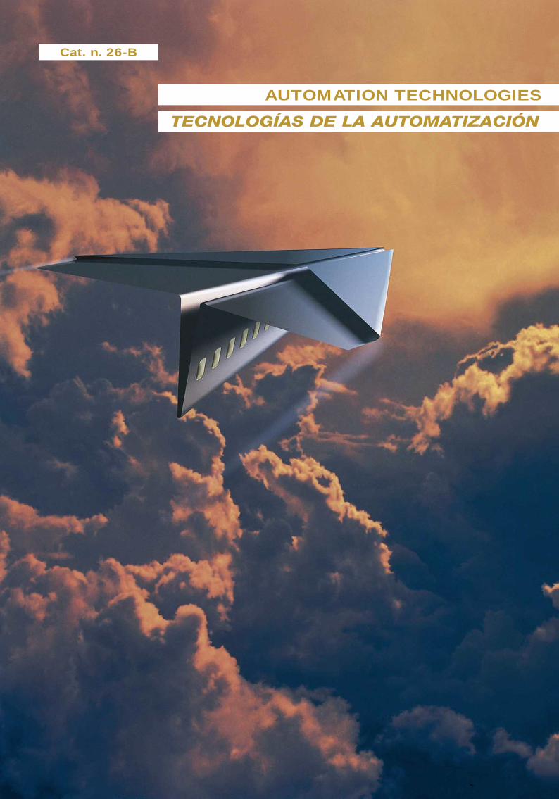
Cat. n. 26-B
AUTOMATION TECHNOLOGIES
TECNOLOGÍAS DE LA AUTOMATIZACIÓN
All rights reserved; no part of this publication may be reproduced, stored in any retrieval system, or transmitted in any form or by any means,electronic, mechanical, photocopying, recording, or otherwise without the prior written permission of Elettronica Veneta & IN.EL. S.p.A.
31045 MOTTA D I L IVENZA (T rev i so ) I t a l y – V i a Pos tum ia , 16Tel. 0422 7657 (r.a.) – Fax 0422 860784 – Export Tel. +39 0422 765802 Fax +39 0422 861901 – http://www.elettronicaveneta.com – E-mail: [email protected]
© Elettronica Veneta & IN.EL. S.p.A. 2002
Graphics and layout - Diseño gráfico y compaginaciónEditorial Coordinator and Promoter - Coordinador editorial y Promotor
Elettronica Veneta & IN.EL. - Marketing
Printed in Italy by GFP/Pn
23-A, 23-B
20-A
21-A, 21-B
35-A
33-A
34-A
38
39
27-A, 27-B
40
26 (26-A, 26-B, 26-C)
32-A, 32-B
25-A
24
37
36
29-A
“dedicated” / “dedicado”
22-A
PRESENTS
THE LIST OF THE CATALOGUES OF THE
“EXCELLENCE LABORATORIES”FOR THE TRAINING AND THE RESEARCH IN THE
THIRD MILLENNIUM
PRESENTA
LA LISTA DE CATÁLOGOS DE LOS
“LABORATORIOS DE EXCELENCIA”PARA LA FORMACIÓN Y LA INVESTIGACIÓN EN EL
TERCER MILENIO Catalogue
ELECTRICAL ENGINEERING
ELECTRONICS, INSTRUMENTATION
AND PROCESS CONTROL
TELECOMMUNICATIONS AND TELEMATIC
INTERACTIVE PRACTICAL ELECTRONIC SYSTEM
AUTOTRONICS
BIOMEDICAL EQUIPMENT
MAINTENANCE TECHNICIAN®
CONSUMER ELECTRONICS TECHNICIAN®
HYDRONICS
THERMOTRONICS
EDUCATIONAL CIB®
(Computer Integrated Building)
AUTOMATION TECHNOLOGIES
MECHATRONICS:
(CAD-CAM-CNC-FMS-CIM)
INDUSTRIAL PROCESS CONTROLS
INDUSTRIAL CHEMISTRY
EXPERIMENTAL CHEMISTRY LABORATORY
ECOLOGY
FOOD PROCESSING TECHNOLOGIES®
“HIGH TECH” MILITARY LABORATORY
MULTIMEDIA AUDIOVISUAL SYSTEMS
ELECTROTECNIA
ELECTRÓNICA Y
CONTROL DE PROCESOS
TELECOMUNICACIONES Y TELEMÁTICA
ELECTRÓNICA PRÁCTICA INTERACTIVA
AUTOTRÓNICA
MANTENIMIENTO DE
EQUIPOS ELECTROMÉDICOS®
MANTENIMIENTO DE ELECTRODOMÉSTICOS®
HIDRÓNICA
TERMOTRÓNICA
EDUCATIONAL CIB®
(Computer Integrated Building)
AUTOMATIZACIÓN
MECATRÓNICA:
(CAD-CAM-CNC-FMS-CIM)
CONTROL DE PROCESOS
QUÍMICA INDUSTRIAL
LABORATORIO DE QUÍMICA EXPERIMENTAL
ECOLOGÍA
FOOD-PROCESSING TECHNOLOGIES®
“HIGH TECH” MILITARY LABORATORY
SISTEMAS AUDIOVISUALES MULTIMEDIA

© Elettronica Veneta & IN.EL. S.p.A.
IDEAS, PROJECTS AND “INTELLIGENT SYSTEMS” FOR TRAINING
IN THE THIRD MILLENNIUM
ELETTRONICA VENETA & IN.EL. IS A SPECIAL COMPANY: ITHAS BEEN INVENTING EDUCATIONAL SYSTEMS SINCE 1963.TEACHING IS THE SCIENCE ALLOWING THE TRAINING OFYOUNG STUDENTS FOR THEIR FUTURE WORKING LIFE.
EDUCATION IS AN INVESTMENT WHICH ALLOWS MAN TOTAKE AN ACTIVE PART IN NEW TECHNOLOGIES. MAN IS THEPRIME STRATEGIC RESOURCE NECESSARY TO THEECONOMICAL, SOCIAL AND CULTURAL GROWTH OF ACOUNTRY. THE MOST DEVELOPED COUNTRIES HAVE THEMOST EFFICIENT SCHOOLS!
ELETTRONICA VENETA HAS GIVEN MUCH TO SCHOOL,THANKS TO ITS EXCELLENT HUMAN RESOURCES, ATEACHING CULTURE OF GREAT VALUE AND ITS TOPQUALITY PRODUCTS.
ONE OF THE PRINCIPLES BEING SOURCE OF INSPIRATIONFOR E.V., COMPANY WITHOUT FRONTIERS, IS THE ABSOLUTERESPECT OF THE NATIONAL CULTURES. A PHILOSOPHYRISING FROM THE EXPERIENCE OF THOSE WHO HAVE BEENFORCED TO CROSS THE NATIONAL BORDERS IN ORDER TOGROW UP AND BE SUCCESSFUL IN THE DIFFERENTINTERNATIONAL MARKETS. THIS HAS BEEN POSSIBLETHANKS TO THE ENTREPRENEURIAL RIGOUR, THE CAPACITYTO LOOK AHEAD AND THE UNCONDITIONED TRUST INQUALITY: QUALITY OF PRODUCTS, QUALITY OF MEN, QUALITYOF TRAINING, QUALITY OF COMMUNICATION.
THE PRODUCTION OF ELETTRONICA VENETA PERFECTLYADAPTS TO EACH COUNTRY AND EACH LEVEL OF STUDY WITHTHE HELP OF MULTIMEDIA, MULTIDISCIPLINARY, MODULAR ANDFLEXIBLE “INTELLIGENT SYSTEMS” WHICH PERMIT A CONSTANTADJUSTMENT TO THE TECHNOLOGICAL PROGRESS.
THE “EXCELLENCE LABORATORIES” ARE DESIGNED ANDPRODUCED FOR:• TRAINING OF YOUNG TECHNICIANS (VOCATIONAL SCHOOLS,
POLYTECHNICS AND UNIVERSITIES) • TECHNOLOGICAL TRAINING FOR SMALL FIRM ENTRE-
PRENEURS• POST-GRADUATE AND POST-DEGREE COURSES• CONTINUOUS TRAINING• TRAINING, RETRAINING AND OUTPLACEMENT OF ADULTS
IN THESE YEARS, ELETTRONICA VENETA HAS BEEN WORKINGFOR THESE OBJECTIVES. THEY HAVE BEEN ACHIEVED WITHTHE CREATION OF 25 TECHNOLOGICAL FIELDS, PRODUCINGTHE SAME NUMBER OF “EXCELLENCE LABORATORIES“ WITHOVER 1.200 PRODUCTS. THIS IS THE REASON WHYELETTRONICA VENETA IS THE WORLD LEADER, IN ITS FIELD,FOR TRAINING AND TECHNOLOGICAL RESEARCH.
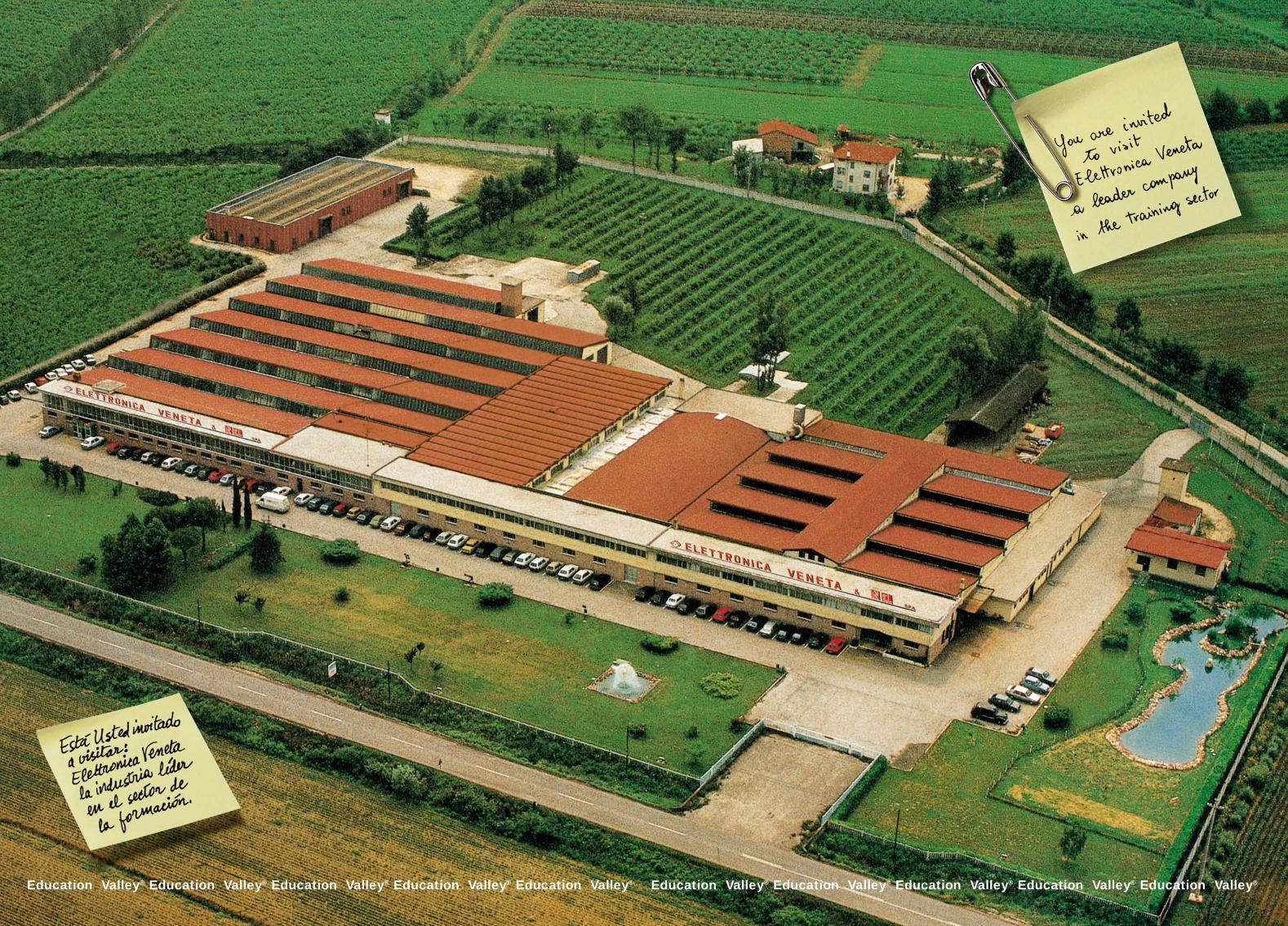
BESIDES, IT REALISED THE “EDUCATION VALLEY®”: THESERVICE SECTOR FOR TEACHERS’ TRAINING SINCE 1975.
THE INDUSTRY COMPLEX COVERS AN AREA OF 52,000 SQ.M.,IN THE GREEN LAND OF TREVISO, NEAR VENICE.
IDEAS, PROYECTOS Y “SISTEMASINTELIGENTES” PARA LA FORMACIÓN
EN EL TERCER MILENIO
ELETTRONICA VENETA & IN.EL. ES UNA EMPRESA SINGULAR:INVENTA DIDÁCTICA DESDE 1963. LA DIDÁCTICA ES LA CIENCIAQUE PERMITE LA FORMACIÓN DE LOS JÓVENES QUE DEBERÁNINGRESAR EN EL MUNDO DEL TRABAJO.
LA FORMACIÓN ES EL MEDIO PARA INVERTIR EN EL HOMBRE,CONVERTIRLO EN EL ACTOR DE LAS INNOVACIONES TECNOLÓGICASY VOLVERLO ARTÍFICE DE SU PROPIO FUTURO. EL HOMBRE ES ELRECURSO ESTRATÉGICO PARA EL DESARROLLO CULTURAL, SOCIALY ECONÓMICO DE UN PAÍS. LOS PAÍSES MÁS AVANZADOS TIENENLAS ESCUELAS CON EL MÁS ALTO GRADO DE EFICACIA.
ELETTRONICA VENETA HA PRESTADO UN GRAN SERVICIO A LASESCUELAS, OFRECIENDO SUS EXCELENTES RECURSOS HUMANOS,UNA INSTRUCCIÓN DIDÁCTICA DE INESTIMABLE VALOR YPRODUCTOS DE ALTA CALIDAD.
UNO DE LOS PRINCIPIOS QUE SIEMPRE HA ANIMADO AELETTRONICA VENETA, EMPRESA SIN FRONTERAS, ES ELABSOLUTO RESPETO POR LAS CULTURAS LOCALES. UNAFILOSOFÍA QUE NACE DE LA EXPERIENCIA DE QUIEN HA TENIDOQUE ATRAVESAR LOS CONFINES NACIONALES PARADESARROLLARSE E IMPONERSE EN LOS DIFERENTES MERCADOSINTERNACIONALES CON LA FUERZA DEL RIGOR EMPRESARIAL, LACAPACIDAD DE MIRAR HACIA EL FUTURO Y LA CONVICCIÓNINCONDICIONAL EN LA CALIDAD: CALIDAD DE LOS PRODUCTOS,CALIDAD DE LOS HOMBRES, CALIDAD DE LA FORMACIÓN YCALIDAD DE LA COMUNICACIÓN.
LOS EQUIPOS FABRICADOS POR ELETTRONICA VENETA SEADAPTAN A CUALQUIER PAÍS Y A CUALQUIER NIVEL DE ESTUDIO,OFRECIENDO “SISTEMAS INTELIGENTES” INTERACTIVOS,MULTIMEDIA, MULTIDISCIPLINARIOS, MODULARES Y FLEXIBLESPARA LA CONSTANTE ADECUACIÓN AL PROGRESO TÉCNICO.
LOS “LABORATORIOS DE EXCELENCIA” HAN SIDO DISEÑADOS YFABRICADOS PARA:• LA FORMACIÓN DE JÓVENES (FORMACIÓN PROFESIONAL,
FORMACIÓN TÉCNICA Y A NIVEL UNIVERSITARIO)• LA FORMACIÓN TECNOLÓGICA PARA PREPARAR EMPRESARIOS
PARA PEQUEÑAS EMPRESAS• LA FORMACIÓN POSDIPLOMA DE EDUCACIÓN SECUNDARIA Y/O
UNIVERSITARIA• LA FORMACIÓN CONTINUA• LA FORMACIÓN DE TRABAJADORES, SU RECALIFICACIÓN Y SU
RECONVERSIÓN
ELETTRONICA VENETA EN ESTOS AÑOS HA TRABAJADO CONAHÍNCO PARA CONSEGUIR ESTOS OBJETIVOS. LAS METAS HANSIDO ALCANZADAS, HABIENDO IMPLEMENTADO BIEN 25 SECTORESTECNOLÓGICOS PARA OTROS TANTOS “LABORATORIOS DEEXCELENCIA” QUE INCLUYEN MÁS DE 1.200 PRODUCTOS; POR ESTARAZÓN, ELETTRONICA VENETA ES LÍDER MUNDIAL EN SU PROPIOSECTOR, PARA LA FORMACIÓN Y LA INVESTIGACIÓN TECNOLÓGICA.
ELETTRONICA VENETA HA REALIZADO TAMBIÉN LA“EDUCATIONAL VALLEY®”, QUE CONSTITUYE DESDE 1975 ELTERCIARIO DIDÁCTICO PARA LA FORMACIÓN Y LA ACTUALIZACIÓNTECNOLÓGICA DE DOCENTES.
LAS INSTALACIONES INDUSTRIALES SE ERIGEN EN UN ÁREA DE52.000 METROS CUADRADOS EN LA VERDE CAMPIÑA DE LACOMARCA DE TREVISO, A POCOS KILÓMETROS DE VENECIA.
Education Valley® Education Valley® Education Valley® Education Valley® Education Valley® Education Valley® Education Valley® Education Valley® Education Valley® Education Valley®

Cat. N. 26-B
ELETTRONICA VENETA SUPPLIES TECHNICAL ASSISTANCE ALL OVER THE WORLD © Elettronica Veneta & IN.EL. S.p.A.
CAT. 26-B AUTOMATION TECHNOLOGIES
CAT. 26-B TECNOLOGÍAS DE LA AUTOMATIZACIÓN
PLC(PROGRAMMABLE LOGIC CONTROL)
PNEUMATICSCOMPONENTS AND SYSTEMSTRAINERSKIT FOR PRACTICAL APPLICATIONS
OIL-HYDRAULICSCOMPONENTS AND SYSTEMSTRAINERS KIT FOR PRACTICAL APPLICATIONSVISUAL SOFTWARE
OIL-HYDRAULICSDATA ACQUISITIONSYSTEM
FACTORY AUTOMATIONMODULAR CIM
ELECTROPNEUMATICSCOMPONENTS AND SYSTEMS TRAINERSKIT FOR PRACTICAL APPLICATIONSROBOTICS
ELECTRO OIL-HYDRAULICSCOMPONENTS AND SYSTEMSTRAINERSKIT FOR PRACTICAL APPLICATIONS
TEMPERATUREPROCESS CONTROL
AUTOMATION PROCESS WITH CONVEYOR
LEVEL AND FLOWPROCESS CONTROL
PRESSUREPROCESS CONTROL
SPEEDPROCESS CONTROL
INDUSTRIAL SYSTEMS
AUTOMATION OF SLIDING GATES
ELECTROPNEUMATIC SYSTEMS
TRAINER WITH ELECTROPNEUMATICACTUATORS
MANIPULATOR ARM
MOTION AND CONTROL OF A THREE-STOREY LIFT
PC AND SOFTWAREPROGRAMMINGDEVICES
PROPORTIONALOIL-HYDRAULICS
FACTORY AUTOMATIONCIM
CAT. N. 26-A CAT. N. 26-C
CAT. N. 26 CIM
CAT. N. 26-B
PROGRAMMINGSOFTWARE
PROGRAMMINGSOFTWARE
PLC SOFTWAREMODULAR PROCESSAUTOMATION CONTROL PC SOFTWARE
PROGRAMMABLE SYSTEMS SIMULATORSIMULATOR WITH PROGRAMMABLE SYSTEMSMASKS TO EXPERIMENT ON:ELEMENTARY LOGIC FUNCTIONS (AND, OR, NOT, ETC.) FUNCTION MODULES (TIMERS, COUNTERS) - THREE-PHASE ASYNCHRONOUS MOTOR ON-OFF STARTER CIRCUIT - THREE-PHASE ASYNCHRONOUS MOTOR REVERSE CIRCUIT - STAR/DELTA STARTER CIRCUIT - STAR/DELTA FORWARD/REVERSE CIRCUIT - LINEAR POSITIONER WITH ASYNCHRONOUS MOTOR - DAHLANDER MOTOR STARTER CIRCUIT - MOTOR STARTING CIRCUIT WITH TWO SEPARATE WINDINGS - MOTOR STARTING CIRCUIT WITH WOUNDED ROTOR - SEQUENTIAL CONVEYORS - CONTROL OF A POWER FACTOR CORRECTION INSTALLATION - ZONE HEATING CONTROL - SEQUENTIAL LIGHT - AUTOMATIC FILLING TANK - 3-TANK AUTOMATIC FILLING SYSTEM - CARBON TREATMENT PROCESS VENTILATION CONTROL INSIDE A GARAGE - TRAFFIC-LIGHT FOR ROADWORKS - TRAFFIC-LIGHT FOR CROSS-ROADS - CONVEYOR - LOADING SYSTEM WITH CONVEYOR BELTS - PRINTING PRESS - TANK LEVEL CONTROL REACTOR WITH AUTOMATIC CONTROL - HOIST WITH FOUR STOPS - 4-PUMP CONTROL FOR TANK FILLING - BLACK LIQUOR PUMPING UNIT - THREE-PUMP OPERATION MONITORING - TANK LEVEL CONTROL VIA PRESSURE SENSORBEVERAGE DISTRIBUTOR - SUBSTANCE MIXER - MECHANICAL MACHINING LINE
AUTOMATIC PIECE WEIGHTINGAND SELECTION SYSTEM
AUTOMATIC CARTESIAN AXESMANIPULATION SYSTEM
AUTOMATIC PIECE SELECTIONSYSTEM WITH ROTATING TABLE
AUTÓMATA PLC
NEUMÁTICACOMPONENTES E INSTALACIONESENTRENADORESKITS PARA APLICACIONES PRÁCTICAS
OLEOHIDRÁULICACOMPONENTES E INSTALACIONESENTRENADORESKITS PARA APLICACIONES PRÁCTICASSOFTWARE VISUAL
OLEOHIDRÁULICASISTEMA DE ADQUISICIÓN DE DATOS
FÁBRICA AUTOMÁTICA CIM MODULAR
ELECTRONEUMÁTICACOMPONENTES E INSTALACIONESENTRENADORESKITS PARA APLICACIONES PRÁCTICASROBÓTICA
ELECTRO-OLEOHIDRÁULICACOMPONENTES E INSTALACIONESENTRENADORESKITS PARA APLICACIONES PRÁCTICASSOFTWARE VISUAL
CONTROL DE PROCESOSDE TEMPERATURA
PROCESO DE AUTOMATIZACIÓN TRANSPORTADOR
CONTROL DE PROCESOSNIVEL Y CAUDAL
CONTROL DE PROCESOS DE PRESIÓN
CONTROL DE PROCESOS DE VELOCIDAD
INSTALACIONES INDUSTRIALES
AUTOMATIZACIÓN DE VERJAS CORREDIZAS
INSTALACIONES ELECTRONEUMÁTICAS
ENTRENADOR EN ACTUADORES ELECTRONEUMÁTICOS
BRAZO MANIPULADOR
MANIPULACIÓN Y CONTROL DE UN ASCENSOR DE TRES PISOS
DISPOSITIVOS DE PROGRAMACIÓN DEL PC Y SOFTWARE
OLEOHIDRÁULICAPROPORCIONAL
FÁBRICA AUTOMÁTICA CIM
CAT. N. 26-A CAT. N. 26-C
CAT. N. 26 CIM
CAT. N. 26-B
SISTEMA DE PROGRAMACIÓN
SOFTWARE DE PROGRAMACIÓN
PLC SOFTWARE CONTROLES AUTOMÁTICOS DE PROCESOS MODULARES
SOFTWARE PARA PC
SIMULADOR DE SISTEMAS PROGRAMABLESMÁSCARAS PARA REALIZAR PRÁCTICAS SOBRE: FUNCIONES LÓGICAS BÁSICAS (AND, OR, NOT, ETC.) – MÓDULOS FUNCIÓN (TEMPORIZADORES, CONTADORES) – CIRCUITO DE ARRANQUE ON-OFF MOTOR ASÍNCRONO TRIFÁSICO – CIRCUITO DE INVERSIÓN DE SENDIDO MOTOR ASÍNCRONO TRIFÁSICO – CIRCUITO DE ARRANQUE EN ESTRELLA-TRIÁNGULO – CIRCUITO DE ARRANQUE E INVERSIÓN EN ESTRELLA-TRIÁNGULO – POSICIONADOR LINEAL CON MOTOR ASÍNCRONO – CIRCUITO DE ARRANQUE MOTOR DAHLANDER – CIRCUITO DE ARRANQUE MOTOR CON DOS BOBINAS SEPARADAS – CIRCUITO DE ARRANQUE MOTOR CON ROTOR DEVANADO – CINTAS TRANSPORTADORAS SECUENCIALES – GESTIÓN DE UNA INSTALACIÓN DE CORRECCIÓNDEL FACTOR DE POTENCIA – CONTROL DE LA CALEFACCIÓN POR ZONAS – LETRERO LUMINOSO SECUENCIAL – SISTEMA DE LLENADO AUTOMÁTICO DE BOTELLAS – SISTEMA DE LLENADO AUTOMÁTICO DE TRES TANQUES – PROCESO DE TRATAMIENTO DEL CARBÓN – CONTROL DE LA VENTILACIÓN EN EL INTERIOR DE UN GARAJE – SEMÁFORO PARA TRABAJOS VIALES – SEMÁFORO PARA CRUCE PEATONAL – SISTEMA DE ACARREO CON CINTA TRANSPORTADORA – SISTEMA DE CARGA CON CINTAS TRANSPORTADORAS – ACUÑADORA – CONTROL DE NIVEL DE UN TANQUE – REACTOR CON CONTROL AUTOMÁTICO – MONTACARGAS CON CUATRO PARADAS – CONTROL DE QUATRO BOMBAS DE LLENADO DE UN TANQUE – SISTEMA DE BOMBEO PARA AGUAS NEGRAS – MONITORIZACIÓN FUNCIONAMENTO DETRES BOMBAS – CONTROL DE NIVEL DE UN TANQUE PORMEDIO DE SENSOR DE PRESIÓN – DISTRIBUIDOR DE BEBIDAS – MEZCLADOR DE SUSTANCIAS – LÍNEA DE MECANIZADO
SISTEMA AUTOMÁTICO DE PESAJEY SELECCIÓN DE PIEZAS
SISTEMA DE MANIPULACIÓN DES EJES CARTESIANOS
SISTEMA AUTOMÁTICO DE SELECCIÓN DE PIEZAS CON MESA GIRATORIA

The last ten years have been a period of fast technologicaldevelopment in industry in the field of industrial automationand, consequently, in training and research for ELETTRONICAVENETA & IN.EL. S.p.A.This development, based on the increasing integration andinteraction between mechanics, electronics and computerscience, is a result of the revolution in the professional profiles,and, consequently, in the training programs, creating new tasksaccording to the needs of industry.In order to grasp the complexity of this development, just thinkof the range of subjects concerning the development processof modern factory automation, CIM:
• Mechanics and electromechanics• Electrical engineering and electronics• Pneumatics and electropneumatics• Oil-hydraulics • Transducers and process control • Electrical servomechanisms• Programmable logic controllers (PLC)• Industrial communication networks • Robotics• Industrial computer science
It is evident that this context produces ever increasing, urgentrequests for continuous up-dating in advanced technologies toface the innovations of industrial automation. Interesting are the requests from the “production”, “design”,“quality control” and “maintenance” areas, which havestressed the need of a proper educational area, which stronglyinvolved all fields of ELETTRONICA VENETA & IN. EL. S.p.A.,in the development of advanced educational proposals.The laboratories for the study of “AUTOMATIONTECHNOLOGIES” introduced in this catalogue, have beendesigned, developed and carried out with totally industrialtechniques and components combining characteristics of:
• Modularity• Flexibility • Expandability • Interactivity
This offers the possibility to design, develop and organize fortraining, retraining and up-dating courses, at all levels,differentiating the programs according to the user’s needs.
31045 MOTTA DI L IVENZA (Trev iso ) I ta l y – V ia Postumia , 16Tel. 0422 7657 (r.a.) – Fax 0422 860784 – Export Tel. +39 0422 765802 Fax +39 0422 861901 – http://www.elettronicaveneta.com – E-mail: [email protected]
La última década ha representado, para la automatizaciónindustrial, un período caracterizado por un rápido desarrollotecnológico y aplicativo en la industria y, consecuentemente,en la formación y la investigación por parte de ELETTRONICAVENETA & IN.EL. S.p.A.Dicho desarrollo, basado en una creciente integración einteracción entre la mecánica, la electrónica y la informática, harevolucionado y redefinido totalmente los perfiles profesionales,así como también los programas de formación, creando nuevoscometidos en línea con los requerimientos de la industria.Para darse cuenta de la complejidad de la referida renovación,piénsese a las temáticas involucradas en el proceso dedesarrollo de la moderna fábrica automática CIM, que son:
• Mecánica y electromecánica• Electrotecnia y electrónica• Neumática y electroneumática• Oleohidráulica• Transductores y controles de procesos• Accionamientos eléctricos• Autómatas lógicos programables (PLC)• Redes de comunicación industrial• Robótica • Informática industrial
Es evidente que en este contexto resulten cada vez más numerosos,diversificados y apremiantes los requerimientos de actualizacióncontinua utilizando tecnologías avanzadas para poder responder alas innovaciones del sector de la automatización industrial.Cabe observar que los referidos requerimientos –procedentes delas áreas de “producción”, “diseño”, “control de calidad” y“mantenimiento”– han determinado la necesidad de disponer de unárea de formación adecuada que ha involucrado de formasignificativa todos los sectores implementados por ELETTRONICAVENETA & IN. EL. S.p.A. en el desarrollo de propuestas avanzadas.Los laboratorios para el estudio de las “TECNOLOGÍAS DE LAAUTOMATIZACIÓN” que se presentan en este catálogo han sidodiseñados, desarrollados y realizados con técnicas y componentestotalmente industriales aunando características de:
• Modularidad• Flexibilidad• Ampliabilidad• Interactividad
lo cual ha permitido el diseño, el desarrollo y la organización deintervenciones de formación, investigación, recualificación yactualización, a cualquier nivel, diferenciando los programas deacuerdo a las exigencias del usuario.
Cat. N. 26-B
INTRODUCTION PRESENTACIÓN
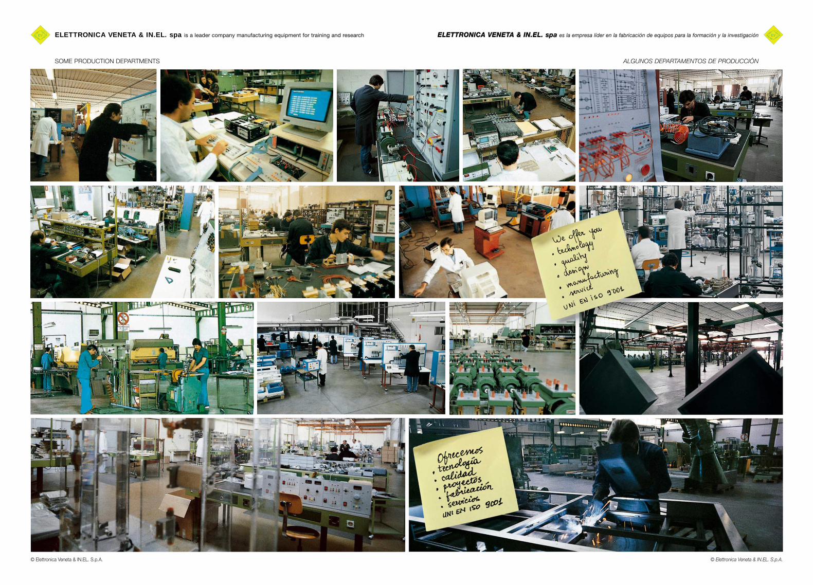
ELETTRONICA VENETA & IN.EL. spa es la empresa líder en la fabricación de equipos para la formación y la investigaciónELETTRONICA VENETA & IN.EL. spa is a leader company manufacturing equipment for training and research
SOME PRODUCTION DEPARTMENTS ALGUNOS DEPARTAMENTOS DE PRODUCCIÓN
© Elettronica Veneta & IN.EL. S.p.A.© Elettronica Veneta & IN.EL. S.p.A.

PÁG.
CONTROLES AUTOMÁTICOSDE PROCESOS MODULARES B1.1
PLC B2.1
SIMULADOR DE SISTEMASPROGRAMABLES mod. SSP/EV B3.1
APLICACIONES B4.1
CONTROLES DE PROCESOS B5.1
SISTEMAS AUTOMATIZADOS REALES B6.1
SIMULACIÓN DE PROCESOS INDUSTRIALES B7.1
PROTOTIPACIÓN MECÁNICA B8.1
PAGE
MODULAR AUTOMATICPROCESS CONTROLS B1.1
PLC B2.1
PROGRAMMABLE SYSTEMSSIMULATOR mod. SSP/EV B3.1
APPLICATIONS B4.1
PROCESS CONTROLS B5.1
REAL AUTOMATED SYSTEMS B6.1
SIMULATION OF INDUSTRIAL PROCESSES B7.1
MECHANICAL PROTOTYPING B8.1
GENERAL CONTENTS ÍNDICE GENERAL
Cat. N. 26-B
© Elettronica Veneta & IN.EL. S.p.A.

Cat. N. 26-BCat. N. 26-B
ELETTRONICA VENETA PROPORCIONA ASISTENCIA TÉCNICA EN TODO EL MUNDO© Elettronica Veneta & IN.EL. S.p.A.ELETTRONICA VENETA SUPPLIES TECHNICAL ASSISTANCE ALL OVER THE WORLD © Elettronica Veneta & IN.EL. S.p.A.
THE COMPLETE LABORATORY FOR PROCESS CONTROL AND INDUSTRIALAPPLICATIONS WITH HUGE INDUSTRIAL PROCESS SIMULATORS
EL LABORATORIO COMPLETO DE CONTROL DE PROCESOS Y APLICACIONES INDUSTRIALESY SIMULADORES COMPLEJOS UTILIZADOS EN LA INDUSTRIA
Mod. PUT-1/EVTemperature processwith actuator amplifier and thermocouple signal conditioner
Proceso de temperaturacon amplificador paraactuador y A.d.S. paratermopar
Mod. PUP-4/EVPressure process with actuator amplifier and pressure transducersignal conditioner
Proceso de presión conamplificador para actuadory A.d.S. para transductorde presión
Mod. PUV-6/EVAngular speed process withactuator, amplifier and tacho-generator signal conditioner
Proceso de velocidad angularcon amplificador para actuadory A.d.S. para tacogenerador
Mod. HM400/EV3-floor lift
Ascensor de 3 pisos
Mod. C/EVIndustrial installations
Instalaciones eléctricasindustriales
Mod. MR/EVSliding gate automated
control installations
Automatizaciónde verjas corredizas
Mod. D/EVElectropneumatic
installations
Instalacioneselectroneumáticas
Mod. EAT/EVElectropneumatic actuators trainer
Entrenador enactuadores
electroneumáticos
Mod. SSP/EVProgrammable
Systems Simulator
Simuladorde sistemas
programables
Mod. PLC-5A/EV
Mod. RMT/EVRobomatic trainer
Brazo manipuladorneumático
Mod. PUL-2/EVLevel and flow process with actuator amplifier and level and flow transducer signal conditioner
Proceso de nivel y caudalcon amplificador paraactuador y A.d.S. paratransductor de nivel y caudal
© Elettronica Veneta & IN.EL. S.p.A.
Cat. N. 26-B
MODULAR AUTOMATIC PROCESSCONTROLS B1.1
• Module holder frame mod. VF2/EV
• Power supply mod. MU5A/EV
• Temperature process mod. PT/EV
• Level and flow process mod. PLP/EV
• Pressure process mod. PP/EV
• Angular speed process mod. PV/EV
• Linear position process mod. PPL/EV
• Luminosity process mod. CPL/EV
• Force transducer mod. TF/EV
• Linear shift transducer mod. TSL/EV
• Proximity sensors mod. SP/EV
• Industrial interface card mod. MFI-I/EV
• Data acquisition and processingsoftware from the transducers mod. SW-TW/EV
• Software for processsupervision mod. SW-PW/EV
CONTROLES AUTOMÁTICOS DE PROCESOS MODULARES B1.1
• Bastidor porta-módulos mod. VF2/EV
• Fuente de alimentación mod. MU5A/EV
• Proceso de temperatura mod. PT/EV
• Proceso de nivel y caudal mod. PLP/EV
• Proceso de presión mod. PP/EV
• Proceso de velocidad angular mod. PV/EV
• Proceso de posición lineal mod. PPL/EV
• Proceso de luminosidad mod. CPL/EV
• Transductor de fuerza mod. TF/EV
• Transductor de desplazamiento lineal mod. TSL/EV
• Sensores de proximidad mod. SP/EV
• Tarjeta de interfaz industrial mod. MFI-I/EV
• Software para la adquisición y el procesode datos desde los transductores mod. SW-TW/EV
• Software para la supervisiónde los procesos mod. SW-PW/EV
TECNOLOGÍAS DE LA AUTOMATIZACIÓNAUTOMATION TECHNOLOGIES
© Elettronica Veneta & IN.EL. S.p.A.
Cat. N. 26-BAUTOMATION TECHNOLOGIES TECNOLOGÍAS DE LA AUTOMATIZACIÓN
PLC B2.1
• PLC Trainerwith software mod. PLC-5A/EV
• Programmable logic controlsystem with software mod. PLC-5B/EV
• PLC Trainer withFUZZY logicsand software mod. PLC-6/EV
• PLC Trainerwith software mod. PLC-7/EV
• PLC Trainerwith software mod. PLC-8/EV
• PLC Trainerwith software mod. PLC-9/EV
• Simulation and I/Ointerfacing unit mod. PLC-9-IO/EV
• Industrial user panel mod. IOP/EV
• Supervision software packet mod. SVS-1/EV
PLC B2.1
• Entrenador en PLCcon software mod. PLC-5A/EV
• Sistema de control programablecon software mod. PLC-5B/EV
• Entrenador en PLCde lógica FUZZYcon software mod. PLC-6/EV
• Entrenador en PLCcon software mod. PLC-7/EV
• Entrenador en PLCcon software mod. PLC-8/EV
• Entrenador en PLCcon software mod. PLC-9/EV
• Unidad de simulacióne interfaz E/S mod. PLC-9-IO/EV
• Panel operador industrial mod. IOP/EV
• Software de supervisión mod. SVS-1/EV
PROGRAMMABLESYSTEMS SIMULATOR B3.1
• Programmable systemssimulator mod. SSP/EV
SIMULADOR DE SISTEMASPROGRAMABLES B3.1
• Simulador de sistemasprogramables mod. SSP/EV
APPLICATIONS B4.1
• Industrial installation mod. C/EV
• Automation of slidinggates mod. MR/EV
• Electropneumatic installation mod. D/EV
• Trainer for electropneumaticactuators mod. EAT/EV
• Robomatic Trainer mod. RMT/EV
• 3-floor lift mod. HM400/EV
• Automation process withconveyor mod. TSM-700/EV
APLICACIONES B4.1
• Instalaciones industriales mod. C/EV
• Automatización de verjascorredizas mod. MR/EV
• Instalaciones electroneumáticas mod. D/EV
• Entrenador en actuadoreselectroneumáticos mod. EAT/EV
• Brazo manipulador neumático mod. RMT/EV
• Ascensor de 3 pisos mod. HM400/EV
• Proceso de automatizacióncon transportador mod. TSM-700/EV

© Elettronica Veneta & IN.EL. S.p.A.
Cat. N. 26-B TECNOLOGÍAS DE LA AUTOMATIZACIÓNAUTOMATION TECHNOLOGIES
PROCESS CONTROLS B5.1
• Power supply unit mod. UA
• Control Software mod. REG/EV
• Temperature process mod. PUT-1/EV
• Level and flow process mod. PUL-2/EV
• Pressure process mod. PUP-4/EV
• Angular speed process mod. PUV-6/EV
• PID digital regulator forprocess control mod. PID-S/EV
CONTROLES DE PROCESOS B5.1
• Unidad de alimentación mod. UA
• Software de control mod. REG/EV
• Proceso de temperatura mod. PUT-1/EV
• Proceso de nivel y caudal mod. PUL-2/EV
• Proceso de presión mod. PUP-4/EV
• Proceso de velocidad angular mod. PUV-6/EV
• Controlador digital PID paracontrol de procesos mod. PID-S/EV
REAL AUTOMATED SYSTEMS B6.1
• Automatic system for Cartesianmanipulation and drilling mod. SAMF/EV
• Automatic test and selectionsystem with rotating indexed table mod. SATS/EV
• Automatic weighting andselection system mod. SAPS/EV
SISTEMAS AUTOMATIZADOS REALES B6.1
• Sistema automático demanipulación cartesiana y taladrado mod. SAMF/EV
• Sistema automático deprueba y selección de piezas mod. SATS/EV
• Sistema automático depesaje y selección de piezas mod. SAPS/EV
SIMULATION OFINDUSTRIAL PROCESSES B7.1
• Process simulator for moldingplastic materials mod. IMS/EV
• Iron processsimulator mod. SPS/EV
• Packaging processsimulator mod. PPS/EV
SIMULACIÓN DE PROCESOSINDUSTRIALES B7.1
• Simulador de un proceso de moldeode materias plásticas mod. IMS/EV
• Simulador de un procesosiderúrgico mod. SPS/EV
• Simulador de un procesode envasado mod. PPS/EV
MECHANICAL PROTOTYPING B8.1
• Laboratory for mechanicalprototyping mod. LPM/EV
PROTOTIPACIÓN MECÁNICA B8.1
• Laboratorio de prototipaciónmecánica mod. LPM/EV
B1.1© Elettronica Veneta & IN.EL. S.p.A.
PAGE
MODULAR AUTOMATICPROCESS CONTROLS B1.1
• Module holder framemod. VF2/EV B1.4
• Power supplymod. MU5A/EV B1.4
• Temperature processmod. PT/EV B1.5
• Level and flow processmod. PLP/EV B1.5
• Pressure processmod. PP/EV B1.5
• Angular speed processmod. PV/EV B1.6
• Linear position processmod. PPL/EV B1.6
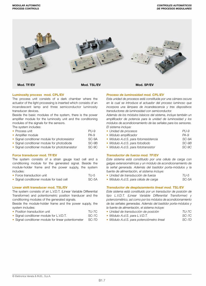
• Luminosity processmod. CPL/EV B1.7
• Force transducermod. TF/EV B1.7
• Linear shift transducermod. TSL/EV B1.7
• Proximity sensorsmod. SP/EV B1.8
PERSONAL COMPUTER INTERFACING
• Industrial interface cardmod. MFI-I/EV B1.8
• Data acquisition and processingsoftware from the transducersmod. SW-TW/EV B1.8
• Software for process supervisionmod. SW-PW/EV B1.8
PÁG.
CONTROLES AUTOMÁTICOS DE PROCESOS MODULARES B1.1
• Bastidor porta-módulosmod. VF2/EV B1.4
• Fuente de alimentaciónmod. MU5A/EV B1.4
• Proceso de temperaturamod. PT/EV B1.5
• Proceso de nivel y caudalmod. PLP/EV B1.5
• Proceso de presiónmod. PP/EV B1.5
• Proceso de velocidad angularmod. PV/EV B1.6
• Proceso de posición linealmod. PPL/EV B1.6
• Proceso de luminosidadmod. CPL/EV B1.7
• Transductor de fuerzamod. TF/EV B1.7
• Transductor de desplazamiento linealmod. TSL/EV B1.7
• Sensores de proximidadmod. SP/EV B1.8
INTERFAZ CON ORDENADORPERSONAL
• Tarjeta de interfaz industrialmod. MFI-I/EV B1.8
• Software para la adquisición y el procesode datos desde los transductoresmod. SW-TW/EV B1.8
• Software para la supervisión de los procesosmod. SW-PW/EV B1.8
Cat. N. 26-BAUTOMATION TECHNOLOGIES TECNOLOGÍAS DE LA AUTOMATIZACIÓN

B1.2© Elettronica Veneta & IN.EL. S.p.A.
B1.3© Elettronica Veneta & IN.EL. S.p.A.
Cat. N. 26-B
CONTROLESAUTOMÁTICOSDE PROCESOSMODULARES
MODULARAUTOMATICPROCESSCONTROLS
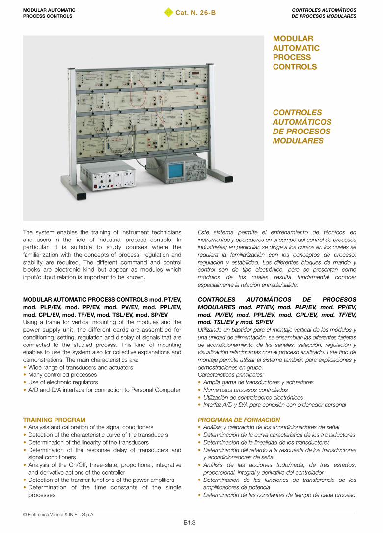
The system enables the training of instrument techniciansand users in the field of industrial process controls. Inparticular, it is suitable to study courses where thefamiliarization with the concepts of process, regulation andstability are required. The different command and controlblocks are electronic kind but appear as modules whichinput/output relation is important to be known.
MODULAR AUTOMATIC PROCESS CONTROLS mod. PT/EV,mod. PLP/EV, mod. PP/EV, mod. PV/EV, mod. PPL/EV,mod. CPL/EV, mod. TF/EV, mod. TSL/EV, mod. SP/EVUsing a frame for vertical mounting of the modules and thepower supply unit, the different cards are assembled forconditioning, setting, regulation and display of signals that areconnected to the studied process. This kind of mountingenables to use the system also for collective explanations anddemonstrations. The main characteristics are: • Wide range of transducers and actuators • Many controlled processes• Use of electronic regulators • A/D and D/A interface for connection to Personal Computer
TRAINING PROGRAM• Analysis and calibration of the signal conditioners • Detection of the characteristic curve of the transducers• Determination of the linearity of the transducers• Determination of the response delay of transducers and
signal conditioners • Analysis of the On/Off, three-state, proportional, integrative
and derivative actions of the controller • Detection of the transfer functions of the power amplifiers• Determination of the time constants of the single
processes
Este sistema permite el entrenamiento de técnicos eninstrumentos y operadores en el campo del control de procesosindustriales; en particular, se dirige a los cursos en los cuales serequiera la familiarización con los conceptos de proceso,regulación y estabilidad. Los diferentes bloques de mando ycontrol son de tipo electrónico, pero se presentan comomódulos de los cuales resulta fundamental conocerespecialmente la relación entrada/salida.
CONTROLES AUTOMÁTICOS DE PROCESOSMODULARES mod. PT/EV, mod. PLP/EV, mod. PP/EV,mod. PV/EV, mod. PPL/EV, mod. CPL/EV, mod. TF/EV,mod. TSL/EV y mod. SP/EVUtilizando un bastidor para el montaje vertical de los módulos yuna unidad de alimentación, se ensamblan las diferentes tarjetasde acondicionamiento de las señales, selección, regulación yvisualización relacionadas con el proceso analizado. Este tipo demontaje permite utilizar el sistema también para explicaciones ydemostraciones en grupo.Características principales:• Amplia gama de transductores y actuadores• Numerosos procesos controlados• Utilización de controladores electrónicos• Interfaz A/D y D/A para conexión con ordenador personal
PROGRAMA DE FORMACIÓN• Análisis y calibración de los acondicionadores de señal• Determinación de la curva característica de los transductores• Determinación de la linealidad de los transductores• Determinación del retardo a la respuesta de los transductores
y acondicionadores de señal• Análisis de las acciones todo/nada, de tres estados,
proporcional, integral y derivativa del controlador• Determinación de las funciones de transferencia de los
amplificadores de potencia• Determinación de las constantes de tiempo de cada proceso
CONTROLES AUTOMÁTICOS DE PROCESOS MODULARES
MODULAR AUTOMATICPROCESS CONTROLS
B1.4© Elettronica Veneta & IN.EL. S.p.A.
• Controller set-up according to:– response at stability limit– process index response– process frequency response
• Detection of the closed-loop processes response with On/Offor Three-state controller
• Detection of the closed-loop processes response with P, P+I,P+D, P+I+D controller
• Open loop processes: comparison of the responses withclosed-loop processes
• Comparison of the sensitivity to the open-loop and closed-loop load variations
• Detection of the permanent state error and the processes,according to the used controller
• Detection of the transient state behavior of the processes,according to the controller time constants
TECHNICAL SPECIFICATIONSThe system is considered in the different subdivisions of group ofmodules and components, so to enable the users to configurethe equipment according to their needs.
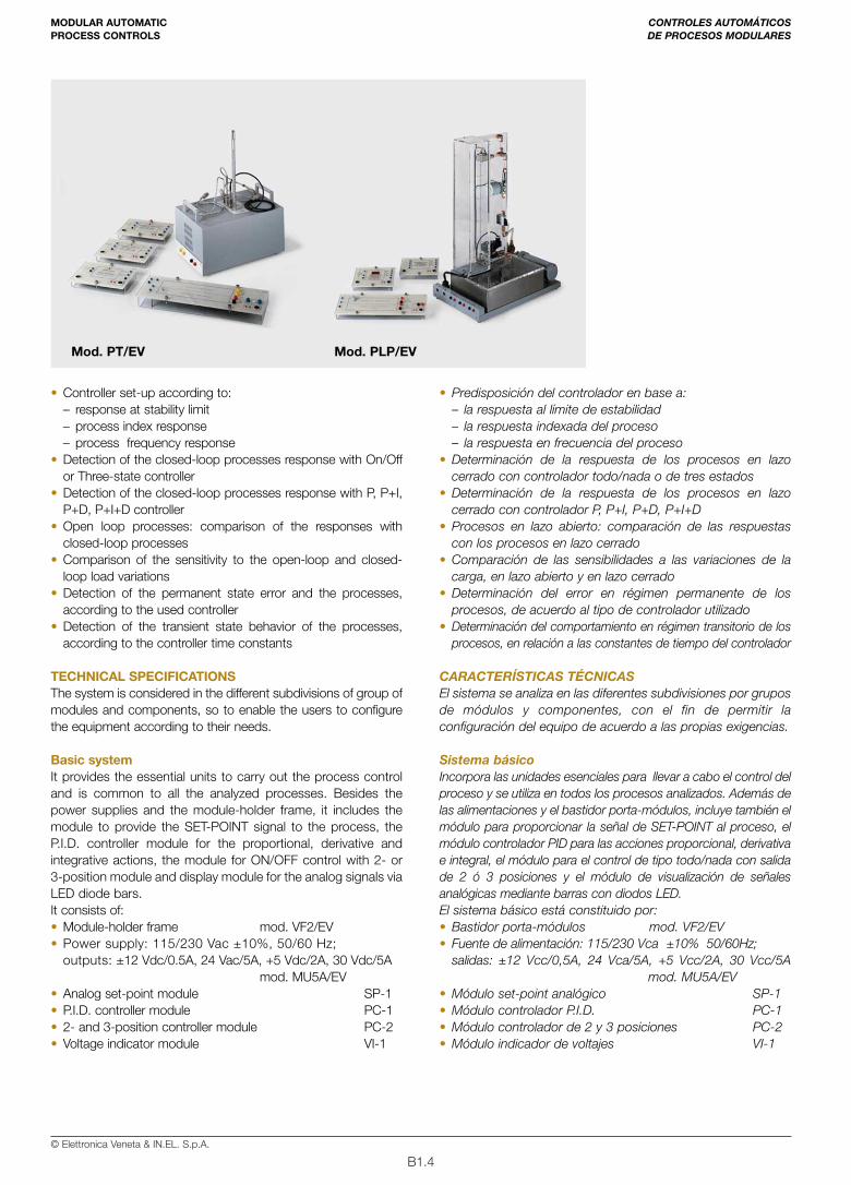
Basic systemIt provides the essential units to carry out the process controland is common to all the analyzed processes. Besides thepower supplies and the module-holder frame, it includes themodule to provide the SET-POINT signal to the process, theP.I.D. controller module for the proportional, derivative andintegrative actions, the module for ON/OFF control with 2- or3-position module and display module for the analog signals viaLED diode bars.It consists of: • Module-holder frame mod. VF2/EV• Power supply: 115/230 Vac ±10%, 50/60 Hz;
outputs: ±12 Vdc/0.5A, 24 Vac/5A, +5 Vdc/2A, 30 Vdc/5Amod. MU5A/EV
• Analog set-point module SP-1• P.I.D. controller module PC-1• 2- and 3-position controller module PC-2• Voltage indicator module VI-1
• Predisposición del controlador en base a:– la respuesta al límite de estabilidad– la respuesta indexada del proceso– la respuesta en frecuencia del proceso
• Determinación de la respuesta de los procesos en lazocerrado con controlador todo/nada o de tres estados
• Determinación de la respuesta de los procesos en lazocerrado con controlador P, P+I, P+D, P+I+D
• Procesos en lazo abierto: comparación de las respuestascon los procesos en lazo cerrado
• Comparación de las sensibilidades a las variaciones de lacarga, en lazo abierto y en lazo cerrado
• Determinación del error en régimen permanente de losprocesos, de acuerdo al tipo de controlador utilizado
• Determinación del comportamiento en régimen transitorio de losprocesos, en relación a las constantes de tiempo del controlador
CARACTERÍSTICAS TÉCNICASEl sistema se analiza en las diferentes subdivisiones por gruposde módulos y componentes, con el fin de permitir laconfiguración del equipo de acuerdo a las propias exigencias.
Sistema básicoIncorpora las unidades esenciales para llevar a cabo el control delproceso y se utiliza en todos los procesos analizados. Además delas alimentaciones y el bastidor porta-módulos, incluye también elmódulo para proporcionar la señal de SET-POINT al proceso, elmódulo controlador PID para las acciones proporcional, derivativae integral, el módulo para el control de tipo todo/nada con salidade 2 ó 3 posiciones y el módulo de visualización de señalesanalógicas mediante barras con diodos LED.El sistema básico está constituido por:• Bastidor porta-módulos mod. VF2/EV• Fuente de alimentación: 115/230 Vca ±10% 50/60Hz;
salidas: ±12 Vcc/0,5A, 24 Vca/5A, +5 Vcc/2A, 30 Vcc/5Amod. MU5A/EV
• Módulo set-point analógico SP-1• Módulo controlador P.I.D. PC-1• Módulo controlador de 2 y 3 posiciones PC-2• Módulo indicador de voltajes VI-1
CONTROLES AUTOMÁTICOS DE PROCESOS MODULARES
MODULAR AUTOMATICPROCESS CONTROLS
Mod. PT/EV Mod. PLP/EV
B1.5© Elettronica Veneta & IN.EL. S.p.A.
Temperature process mod. PT/EVThe process unit includes the thermal actuators consisting in adouble resistor and a fan and three different kinds of usableindustrial temperature transducers (PTC, RTD and thermocouple)Beside the basic modules of the system, there is the poweramplifier module for heating and cooling actuators and theconditioning modules of the signals provided by the three kindsof usable sensors. The system includes:• Process unit PU-1• Amplifier module PA-1A• Signal conditioner module for P.T.C. SC-1A• Signal conditioner module for RTD SC-1B• Signal conditioner module for thermocouple SC-1C
Level and flow process mod. PLP/EVThe process unit consists of a tank with pump to provide theliquid necessary to reach and keep the level. The actuatorconsists of a proportional valve while the level transducerconsists in a pressure sensor set at the bottom of the processtank. A windmill flowmeter with a manual throttle valve set inseries on the delivery pipe enables to carry out flowmeasurements. Beside the basic modules of the system, thereis the power amplifier module for the level and flow actuatorsand the conditioning modules of the signals provided by thetwo level and flow transducers. The system includes:• Process unit PU-2• Amplifier module PA-2• Signal conditioner module for level transducer SC-2A• Signal conditioner module for flow transducer SC-3A
Pressure process mod. PP/EVThe process unit consists of a tank and a compressor activatedby an electrical motor providing the air necessary to reach andkeep the pressure. The actuator consists of a proportional valveand the pressure transducer is piezoresistive.Besides the basic modules of the system, there is also a poweramplifier for the pressure unit and the conditioning modules ofthe signals for the pressure transducer.
Proceso de temperatura mod. PT/EVEsta unidad de procesos está constituida por los actuadorestérmicos, provistos de una doble resistencia, un ventilador y lostres tipos de transductores de temperatura industriales quepueden utilizarse (PTC, termorresistencia y termopar).Además de los módulos básicos del sistema, incluye tambiénel módulo de amplificación de potencia para los actuadores decaldeo y refrigeración, así como también los módulos deacondicionamiento de las señales proporcionadas por los trestipos de sensores que pueden utilizarse. El sistema incluye:• Unidad de procesos PU-1• Módulo amplificador PA-1A• Módulo A.d.S. para P.T.C. SC-1A• Módulo A.d.S. para termorresistencia SC-1B• Módulo A.d.S. para termopar SC-1C
Proceso de nivel y caudal mod. PLP/EVEsta unidad de procesos está constituida por un depósito conbomba para suministrar el líquido requerido para el alcance delnivel y su mantenimiento. El actuador incorpora una válvulaproporcional y el transductor de nivel incorpora un sensor depresión situado en el fondo del depósito de proceso. Uncaudalímetro de torbellino con un estrangulador manualconectado en serie en el envío permite llevar a cabo las medidasde caudal. Además de los módulos básicos del sistema, incluyetambién un amplificador de potencia para la unidad de nivel ycaudal, así como también los módulos de acondicionamiento delas señales para los dos transductores de nivel y caudal.El sistema incluye:• Unidad de procesos PU-2• Módulo amplificador PA-2• Módulo A.d.S. para transductor de nivel SC-2A• Módulo A.d.S. para transductor de caudal SC-3A
Proceso de presión mod. PP/EVEsta unidad de procesos está constituida por un depósito y uncompresor accionado por un motor eléctrico que proporciona el airerequerido para el alcance de la presión y el mantenimiento de lamisma. El actuador incorpora una válvula proporcional y eltransductor de presión es de tipo piezorresistivo. Además de losmódulos básicos del sistema, incluye también el amplificador depotencia para la unidad de presión y los módulos deacondicionamiento de las señales para el transductor de presión.
CONTROLES AUTOMÁTICOS DE PROCESOS MODULARES
MODULAR AUTOMATICPROCESS CONTROLS
Mod. PV/EV Mod. PP/EV
B1.6© Elettronica Veneta & IN.EL. S.p.A.
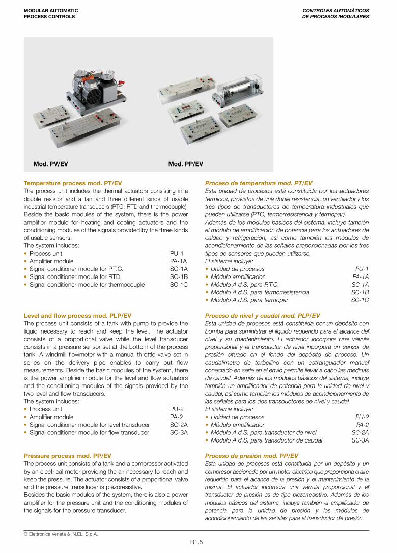
The system includes:• Process unit PU-4• Amplifier module PA-2• Signal conditioner module for pressure transducer SC-4A
Angular speed process mod. PV/EVThe process unit consists of a bidirectional permanent magnetsd.c. motor. A tachogenerator and an incremental encoder ofoptical kind – which are the transducers - are splined on the axis.The actuator consists of a DC motor.Beside the basic modules of the system, there is the poweramplifier module for the angular speed and the conditioningmodules of the signals for the speed and angular position sensors. The system includes:• Process unit PU-6• Amplifier module PA-6• Signal conditioner module for tacho-generator SC-6A• Signal conditioner module for feedback reaction SC-6B• Signal conditioner module for photoelectric
speed transducer SC-6C
Linear position process mod. PPL/EV The microprocessor position control drives the motion of asingle-axis translator by reading from bidirectional incrementalencoder.The microprocessor controller is the processing unit of theposition control and is complete with display and keyboard fordata insertion and display. A D/A converter module is used tocontrol the analog section of the position control while asecond module enables the display of the logic state of theoutput lines of the microprocessor controller. There are also theconditioning modules for the speed and position sensors. Beside the base modules, the system includes:• Process unit PU-7• Amplifier module PA-6• Microprocessor digital control module CU-1• Display and keyboard for module CU-1 DK-1• 12-bit D/A converter module DA-1• 8-bit I/O module IO-1• Signal conditioner module for tachogenerator SC-6A• Signal conditioner module for incremental encoder SC-7A
El sistema incluye:• Unidad de procesos PU-4• Módulo amplificador PA-2• Módulo A.d.S. para transd. de presión SC-4A
Proceso de velocidad angular mod. PV/EVEsta unidad de procesos está constituida por un motor de corrientecontinua bidireccional de imán permanente. En el eje estánensamblados un tacogenerador y un codificador incremental de tipoóptico que constituyen los transductores. El actuador incorpora unmotor de c.c.; además de los módulos básicos del sistema, estápresente también un amplificador de potencia para la unidad develocidad angular y los módulos de acondicionamiento de lasseñales para los sensores de velocidad y posición angular.El sistema incluye:• Unidad de procesos PU-6• Módulo amplificador PA-6• Módulo A.d.S. para tacogenerador SC-6A• Módulo A.d.S. para reacción de armadura SC-6B• Módulo A.d.S. para transductor fotoeléctrico
de velocidad SC-6C
Proceso de posición lineal mod. PPL/EVEl control de posición por microprocesador gobierna elmovimiento de un trasladador de un eje mediante la lectura pormedio de un codificador incremental bidireccional.El controlador por microprocesador es la unidad deprocesamiento del control de posición y está provisto de displayy teclado para la inserción de los datos y la visualización de losmismos. Un módulo convertidor D/A se utiliza para controlar lasección analógica del control de posición, mientras que unsegundo módulo permite visualizar el estado lógico de laslíneas de salida del controlador por microprocesador. Estánpresentes también los módulos de acondicionamiento de lasseñales para los sensores de velocidad y posición.Además de los módulos básicos, el sistema incluye:• Unidad de procesos PU-7• Módulo amplificador PA-6• Módulo control digital por microprocesador CU-1• Display y teclado para módulo CU-1 DK-1• Módulo convertidor D/A de 12 bits DA-1• Módulo de E/S de 8 bits IO-1• Módulo A.d.S. para tacogenerador SC-6A• Módulo A.d.S. para codificador incremental SC-7A
CONTROLES AUTOMÁTICOS DE PROCESOS MODULARES
MODULAR AUTOMATICPROCESS CONTROLS
Mod. CPL/EV Mod. PPL/EV
B1.7© Elettronica Veneta & IN.EL. S.p.A.
Luminosity process mod. CPL/EVThe process unit consists of a dark chamber where theactuator of the light processing is inserted which consists of anincandescent lamp and three semiconductor luminositytransducer devices.Beside the basic modules of the system, there is the poweramplifier module for the luminosity unit and the conditioningmodules of the signals for the sensors. The system includes:• Process unit PU-9• Amplifier module PA-9• Signal conditioner module for photoresistor SC-9A• Signal conditioner module for photodiode SC-9B• Signal conditioner module for phototransistor SC-9C
Force transducer mod. TF/EVThe system consists of a strain gauge load cell and aconditioning module for the generated signal. Beside themodule-holder frame and the power supply, the systemincludes:• Force transduction unit TU-5• Signal conditioner module for load cell SC-5A
Linear shift transducer mod. TSL/EVThe system consists of an L.V.D.T. (Linear Variable DifferentialTransformer) and potentiometric position tranducer and theconditioning modules of the generated signals. Beside the module-holder frame and the power supply, thesystem includes:• Position transduction unit TU-7C• Signal conditioner module for L.V.D.T. SC-7C• Signal conditioner module for linear potentiometer SC-7D
Proceso de luminosidad mod. CPL/EVEsta unidad de procesos está constituida por una cámara oscuraen la cual se introduce el actuador del proceso luminoso queincorpora una lámpara de incandescencia y tres dispositivostransductores de luminosidad con semiconductor.Además de los módulos básicos del sistema, incluye también unamplificador de potencia para la unidad de luminosidad y losmódulos de acondicionamiento de las señales para los sensores. El sistema incluye:• Unidad de procesos PU-9• Módulo amplificador PA-9• Módulo A.d.S. para fotorresistencia SC-9A• Módulo A.d.S. para fotodiodo SC-9B• Módulo A.d.S. para fototransistor SC-9C
Transductor de fuerza mod. TF/EVEste sistema está constituido por una célula de carga congalgas extensiométricas y un módulo de acondicionamiento dela señal generada. Además del bastidor porta-módulos y lafuente de alimentación, el sistema incluye:• Unidad de transducción de fuerza TU-5• Módulo A.d.S. para célula de carga SC-5A
Transductor de desplazamiento lineal mod. TSL/EVEste sistema está constituido por un transductor de posición detipo L.V.D.T. (Linear Variable Differential Transformer) ypotenciométrico, así como por los módulos de acondicionamientode las señales generadas. Además del bastidor porta-módulos yla fuente de alimentación, el sistema incluye:• Unidad de transducción de posición TU-7C• Módulo A.d.S. para L.V.D.T. SC-7C• Módulo A.d.S. para potenciómetro lineal SC-7D
CONTROLES AUTOMÁTICOS DE PROCESOS MODULARES
MODULAR AUTOMATICPROCESS CONTROLS
Mod. TF/EV Mod. TSL/EV Mod. SP/EV
B1.8© Elettronica Veneta & IN.EL. S.p.A.
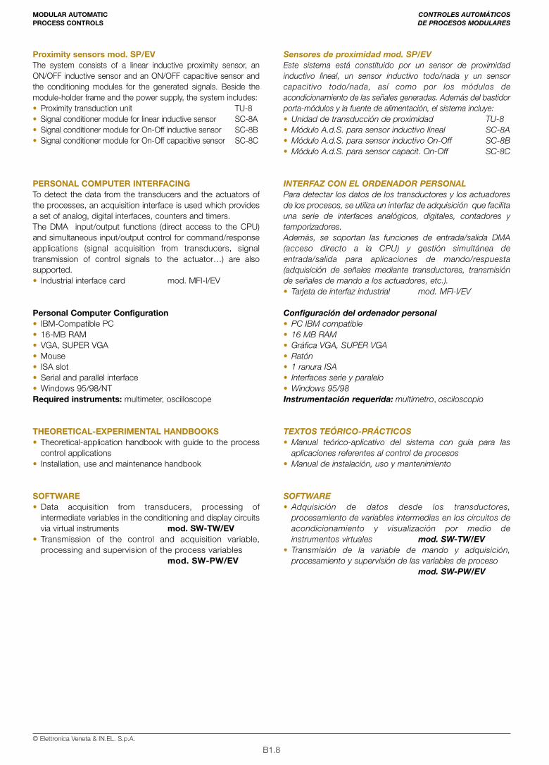
Proximity sensors mod. SP/EVThe system consists of a linear inductive proximity sensor, anON/OFF inductive sensor and an ON/OFF capacitive sensor andthe conditioning modules for the generated signals. Beside themodule-holder frame and the power supply, the system includes: • Proximity transduction unit TU-8 • Signal conditioner module for linear inductive sensor SC-8A• Signal conditioner module for On-Off inductive sensor SC-8B• Signal conditioner module for On-Off capacitive sensor SC-8C
PERSONAL COMPUTER INTERFACINGTo detect the data from the transducers and the actuators ofthe processes, an acquisition interface is used which providesa set of analog, digital interfaces, counters and timers.The DMA input/output functions (direct access to the CPU)and simultaneous input/output control for command/responseapplications (signal acquisition from transducers, signaltransmission of control signals to the actuator…) are alsosupported.• Industrial interface card mod. MFI-I/EV
Personal Computer Configuration • IBM-Compatible PC• 16-MB RAM • VGA, SUPER VGA • Mouse• ISA slot• Serial and parallel interface• Windows 95/98/NT Required instruments: multimeter, oscilloscope
THEORETICAL-EXPERIMENTAL HANDBOOKS • Theoretical-application handbook with guide to the process
control applications • Installation, use and maintenance handbook
SOFTWARE• Data acquisition from transducers, processing of
intermediate variables in the conditioning and display circuitsvia virtual instruments mod. SW-TW/EV
• Transmission of the control and acquisition variable,processing and supervision of the process variables
mod. SW-PW/EV
Sensores de proximidad mod. SP/EV Este sistema está constituido por un sensor de proximidadinductivo lineal, un sensor inductivo todo/nada y un sensorcapacitivo todo/nada, así como por los módulos deacondicionamiento de las señales generadas. Además del bastidorporta-módulos y la fuente de alimentación, el sistema incluye: • Unidad de transducción de proximidad TU-8 • Módulo A.d.S. para sensor inductivo lineal SC-8A• Módulo A.d.S. para sensor inductivo On-Off SC-8B• Módulo A.d.S. para sensor capacit. On-Off SC-8C
INTERFAZ CON EL ORDENADOR PERSONALPara detectar los datos de los transductores y los actuadoresde los procesos, se utiliza un interfaz de adquisición que facilitauna serie de interfaces analógicos, digitales, contadores ytemporizadores.Además, se soportan las funciones de entrada/salida DMA(acceso directo a la CPU) y gestión simultánea deentrada/salida para aplicaciones de mando/respuesta(adquisición de señales mediante transductores, transmisiónde señales de mando a los actuadores, etc.).• Tarjeta de interfaz industrial mod. MFI-I/EV
Configuración del ordenador personal• PC IBM compatible• 16 MB RAM • Gráfica VGA, SUPER VGA• Ratón• 1 ranura ISA• Interfaces serie y paralelo• Windows 95/98Instrumentación requerida: multímetro, osciloscopio
TEXTOS TEÓRICO-PRÁCTICOS• Manual teórico-aplicativo del sistema con guía para las
aplicaciones referentes al control de procesos• Manual de instalación, uso y mantenimiento
SOFTWARE• Adquisición de datos desde los transductores,
procesamiento de variables intermedias en los circuitos deacondicionamiento y visualización por medio deinstrumentos virtuales mod. SW-TW/EV
• Transmisión de la variable de mando y adquisición,procesamiento y supervisión de las variables de proceso
mod. SW-PW/EV
CONTROLES AUTOMÁTICOS DE PROCESOS MODULARES
MODULAR AUTOMATICPROCESS CONTROLS

B2.1© Elettronica Veneta & IN.EL. S.p.A.
PAGE
PLC B2.1
• PLC Trainer with softwaremod. PLC-5A/EV B2.3
• Programmable logic control systemwith softwaremod. PLC-5B/EV B2.7
• PLC Trainer with FUZZY logicsand softwaremod. PLC-6/EV B2.11
• PLC Trainer with softwaremod. PLC-7/EV B2.15
• PLC Trainer with softwaremod. PLC-8/EV B2.19
• PLC Trainer with softwaremod. PLC-9/EV B2.23
• Simulation and I/O interfacing unitmod. PLC-9-IO/EV B2.27
• Industrial user panelmod. IOP/EV B2.29
• Supervision software packetmod. SVS-1/EV B2.30
PÁG.
PLC B2.1
• Entrenador en PLC con softwaremod. PLC-5A/EV B2.3
• Sistema de control programablecon softwareMod. PLC-5B/EV B2.7
• Entrenador en PLC de lógica FUZZYcon softwaremod. PLC-6/EV B2.11
• Entrenador en PLC con softwaremod. PLC-7/EV B2.15
• Entrenador en PLC con softwaremod. PLC-8/EV B2.19
• Entrenador en PLC con softwaremod. PLC-9/EV B2.23
• Unidad de simulación e interfaz E/Smod. PLC-9-IO/EV B 2.27
• Panel operador industrialmod. IOP/EV B2.29
• Software de supervisiónmod. SVS-1/EV B2.30
Cat. N. 26-B PLCPLC

B2.2© Elettronica Veneta & IN.EL. S.p.A.

B2.3© Elettronica Veneta & IN.EL. S.p.A.
Cat. N. 26-B
ENTRENADOREN PLC CONSOFTWAREmod. PLC-5A/EV
PLC TRAINERWITH SOFTWAREmod. PLC-5A/EV
Thanks to microelectronics, enabling the creation of more andmore powerful microprocessors, Programmable LogicControllers (PLC) have been available on the market from thebeginning of the ’70s. These are microprocessor devicesemployed for industrial automation. In this field, the PLCs have created great innovations onindustrial automation, almost completely substituting the use ofwired logic.In fact, the operations they develop can be summed up asfollows:• Logical functions • Arithmetic operations• Counting and timing• Process regulations • Sequential process controlsThe development of computer science technologies createdthe possibility of network connection between PLCs, sensors,actuators. In this way, automation and supervision can be easilyoperated even in great industrial systems.With this in mind, the trainer mod. PLC-5A/EV has beendesigned for high level training of technicians working in theindustry on problems concerning programming of PLC.Furthermore, the trainer teaching value is enriched byapplications ranging from industrial installation to robotics, fromsimulated systems to real industrial process controls.
Gracias a la evolución de la microelectrónica, que ha permitidola implementación de microprocesadores cada vez máspotentes, a partir del inicio de los setenta ha permitido laentrada en el mercado de los autómatas lógicos programables(Programmable Logic Controller: PLC).Los autómatas son dispositivos de microprocesador que se utilizanen las problemáticas referentes a la automatización industrial.La llegada de los PLCs en este sector ha permitido grandesinnovaciones en la automatización industrial, reemplazandocasi totalmente el uso de la lógica cableada; de hecho, lasoperaciones que los mismos desarrollan pueden resumirse en:• Funciones de tipo lógico • Operaciones aritméticas• Contajes y temporizaciones• Controles de procesos • Control de procesos secuencialesIgualmente, el desarrollo de las tecnologías informáticas hapermitido el conexionado en red de PLCs, sensores yactuadores; de esta forma, es posible realizar fácilmente laautomatización y la supervisión de instalaciones industrialesincluso de grandes dimensiones. Bajo esta óptica, el Entrenadormod. PLC-5A/EV ha sido diseñado para una formación de altonivel, de los técnicos que operan en la industria, sobre lasproblemáticas referentes a la programación de los PLCs.El valor didáctico del entrenador aumenta aún más, ya queinvolucra aplicaciones que van desde las instalacionesindustriales hasta la robótica, desde los sistemas simuladoshasta los controles de procesos industriales reales.
PLCPLC
B2.4© Elettronica Veneta & IN.EL. S.p.A.
PLC TRAINER WITH SOFTWARE mod. PLC-5A/EVThe trainer mod. PLC-5A/EV is the necessary tool for trainingtechnicians operating in industry for the maintenance and thedesign of installations. Carried out with industrial components,the trainer mod. PLC-5A/EV enables the development of a solidexperimentation and a high content of knowledge, onprogramming the PLC.The training program includes a wide range of applications:• Industrial installation• Robotics• Automation with conveyor• Process controlsThe PLC of trainer mod. PLC-5A/EV is one of the most used inthe industry and provides many digital inputs and outputs bymeans of terminals with two diameters (Ø 4 mm and Ø 2 mm)present on the front panel of the trainer. One of the digital inputsis used for quick counting, too.As concerns the digital outputs, these are available as relay ortransistor outputs for all those applications needing quickertimes. The logic state of the digital inputs and outputs isdisplayed via LED diodes on the PLC.Two analog inputs (10 bit) and an analog output (12 bit) areavailable for exercises involving process control. With tworotating potentiometers and an inner stabilizer, you can adjustthe voltage levels across the analog inputs. In this way, noexternal power supply is necessary for the generation ofreferences.The front panel of the trainer mod. PLC-5A/EV shows the silkscreen panel of the diagrams and the inner components of theequipment, complete with every single name. This wide andclear vision of the system increases the teaching value,facilitating the layout of connections and the development ofthe exercises.A 3 1/2 -digit digital voltmeter displays the voltage across theanalog inputs and outputs according to the position of therotating switch. The programming software in WIN 95/98 orsuperior, provided with the trainer mod. PLC-5A/EV, enablesthe easy development of programs of exercises with PLC in themost used languages of industrial automation: AWL, KOP, FUP.The connection between Personal Computer and PLC is madevia the supplied serial interface cable RS-232. The development of the exercises is guided effectively by thetheoretical/experimental handbooks available with the trainer.
TRAINING PROGRAMThe trainer mod. PLC-5A/EV enables the theoretical analysisand the experiments on the following main exercises:• PLC architecture• Processing of the instructions: cycle• Synchronous, asynchronous and priority cycles • Times of execution, cycle and reaction • Boolean Algebra • Basic programming in: AWL, KOP, FUP• Combinatory logic functions• Sequential logic functions • Addressing• Timers & counters• Clock generators
ENTRENADOR EN PLC CON SOFTWARE mod. PLC-5A/EVEl Entrenador mod. PLC-5A/EV constituye el soporte necesariopara la formación de técnicos que operan en la industria, tanto anivel de mantenimiento de las instalaciones como a nivel de diseñode las mismas. Está realizado con componentes industriales ypermite la realización de prácticas detalladas y con un elevadocontenido de conocimientos sobre la programación de los PLCs. El programa de formación involucra en este contexto un amplioabanico de aplicaciones:• Instalaciones industriales• Robótica• Automatización con transportadores• Controles de procesosEl PLC a bordo del Entrenador mod. PLC-5A/EV es uno de entrelos más difundidos en ámbito industrial y facilita una grancantidad de entradas y salidas digitales asequibles a través determinales con dos diámetros (Ø 4 mm y Ø 2 mm) presentes enel panel delantero del entrenador. Una de las entradas digitalesrealiza también el contaje rápido. Las salidas digitales estándisponibles como salidas de relé o transistor para todas aquellasaplicaciones que requieran tiempos más rápidos. El estadológico de las entradas y las salidas digitales se visualiza pormedio de diodos LEDs incorporados en el PLC. Dos entradasanalógicas (10 bits) y una salida analógica (12 bits) permiten larealización de prácticas en las cuales se utiliza el control deprocesos. Es posible regular el nivel de las tensiones en lasentradas analógicas a través de dos potenciómetros rotativos yun estabilizador interno; de esta forma, se evita el uso de fuentesde alimentación externas para la generación de referencias.El panel delantero del Entrenador mod. PLC-5A/EV lleva larepresentación sinóptica serigrafiada de los esquemas y loscomponentes internos del equipo, completa de todas lasnomenclaturas. Esta amplia y clara visión del sistema aumentael valor didáctico del mismo, facilitando la preparación de losconexionados y la realización de las prácticas.Un voltímetro digital de 3 1/2 cifras visualiza la tensión de lasentradas analógicas o la salida analógica, en base a la posiciónde un selector rotativo.El software de programación en entorno WIN 95/98 o superiorproporcionado junto con el Entrenador mod. PLC-5A/EV,permite un fácil desarrollo de programas para prácticas con elPLC en los más difundidos lenguajes de automatizaciónindustrial: AWL, KOP, FUP.El conexionado entre el ordenador personal y el PLC se lleva a caboa través del cable de interfaz serie RS-232 en dotación. Por último, la realización de las prácticas es guiada con eficacia porlos manuales teórico-prácticos disponibles junto con el entrenador.
PROGRAMA DE FORMACIÓN El Entrenador mod. PLC-5A/EV permite el análisis teórico y larealización de prácticas sobre los siguientes principales temas:• Arquitectura de un PLC• Procesamiento de las instrucciones: concepto de ciclo• Ciclos síncronos, asíncronos y con prioridades• Tiempos de ejecución, ciclo y reacción• Álgebra de Boole• Programación básica en los lenguajes: AWL, KOP, FUP• Funciones de lógica combinacional• Funciones de lógica secuencial• Direccionamientos• Temporizadores y contadores• Generadores de reloj
PLCPLC
B2.5© Elettronica Veneta & IN.EL. S.p.A.
• Monostable circuits• Bistable circuits• Algebraic operations: sum, subtraction, and multiplication• BCD/binary conversions• Binary/BCD conversions• Structured programming techniques • Types of base data• Types of structured data • Function blocks which can be parameterized• Programmable function blocks• Typical applications
– Programmable systems simulator (mod. SSP/EV)– Industrial installation (mod. C/EV)– Automation of sliding gates (mod. MR/EV) – Electropneumatic installation (mod. D/EV)– Trainer for electropneumatic actuators (mod. EAT/EV)– Robomatic Trainer (mod. RMT/EV)– 3-floor lift (mod. HM400/EV)– Automation process with conveyor (mod. TSM-700/EV)– PID regulation of
Temperature process (mod. PUT-1/EV)Level and flow process ( mod. PUL-2/EV)Pressure process (mod. PUP-4/EV)Angular speed process (mod. PUV-6/EV)
• Communication of a PLC with PC: modes• Diagnostics of the inputs and outputs • Diagnostics of the inner states• I/O forcing and inner variables• PLC networks (Master/Slave)
TECHNICAL SPECIFICATIONS • Sheet steel container, chemically treated and painted with
epoxy paint • Side handles to easily move the equipment in the laboratory• Front panel, in insulating material, with silk screen
representation of the diagrams and inner components of theequipment
• 24 Vdc/3 A power supply for control of the digital inputs andoutputs. With electronic protection against short-circuits andoverloads
• 24 Vac/3 A power supply for relay output control. With fuseprotection against overloads
• 1 3 1/2-digit digital voltmeter for measurement of the voltagepresent across the inputs or the analog output. 0.1 Vdcresolution
• 1 rotating switch for voltmeter input selection• 2 analog inputs in the 0..10 Vdc range• 1 analog output in the 0..10 Vdc range• 2 rotating potentiometers for setting up the analog references• Inner voltage reference obtained via 24 Vdc inner stabilizer• 16 24-Vdc digital inputs of which 1 (I 0.0) for fast counting
(f=3 kHz)• Digital input simulator with permanent and pulse state
switches • 14 24-Vdc digital transistor outputs • Safety terminals, standard Ø 4 mm and Ø 2 mm for
connection of the inputs and outputs to external devices• Digital outputs interfacing:
– With relay ranging between 10 Aac / 2 Adc – Transistor for fast applications
• Circuitos monoestables• Circuitos biestables• Operaciones algebraicas: suma, resta, multiplicación• Conversiones BCD/binario• Conversiones binario/BCD • Técnicas de programación estructurada• Tipos de datos básicos• Tipos de datos estructurados• Bloques función parametrizables• Bloques función programables• Aplicaciones típicas
– Simulador de sistemas programables (mod. SSP/EV)– Instalaciones eléctricas industriales (mod. C/EV)– Automatización de verjas corredizas (mod. MR/EV)– Instalaciones electroneumáticas (mod. D/EV)– Entrenador en actuadores electroneumáticos (mod. EAT/EV)– Brazo manipulador neumático (mod. RMT/EV)– Ascensor de 3 pisos (mod. HM400/EV)– Proceso de automatización con transportador (mod. TSM-700/EV)– Control PID de
Proceso de temperatura (mod. PUT-1/EV)Proceso de nivel y caudal (mod. PUL-2/EV)Proceso de presión (mod. PUP-4/EV)Proceso de velocidad angular (mod. PUV-6/EV)
• Comunicación de un PLC con el PC: modalidades• Diagnóstico de entradas y salidas• Diagnóstico de los estados internos• Forzamiento E/S y variables internas• Redes del PLC (Maestro/Esclavo)
CARACTERÍSTICAS TÉCNICAS • Estructura en chapa de acero, tratada químicamente y pintada
con barniz epoxi• Asideros laterales no sobresalientes para un fácil desplazamiento
en el laboratorio• Panel delantero, en material aislante, con representación
sinóptica y serigrafiada de los esquemas y los componentespuestos en el interior del equipo
• Fuente de alimentación 24 Vcc/3 A para el gobierno de lasentradas digitales y las salidas digitales. Incluida la protecciónelectrónica contra las sobrecargas y los cortocircuitos
• Fuente de alimentación 24 Vca /3 A para el mando de lassalidas de relé. Incluida la protección por fusible contra lassobrecorrientes
• Voltímetro digital de 3 1/2 dígitos para la medida de la tensión presenteen las entradas analógicas o la salida analógica. Resolución: 0,1 Vcc
• Selector rotativo para la selección de la entrada del voltímetro• 2 entradas analógicas en el margen 0..10 Vcc• 1 salida analógica en el margen 0..10 Vcc• 2 potenciómetros rotativos para la selección de referencias
analógicas• Referencia de tensión interna obtenida a través de un
estabilizador interior de 24 Vcc• 16 entradas digitales de 24 Vcc, de las cuales 1 (I 0.0) para
contaje rápido (f=3 kHz)• Simulador para las entradas digitales con interruptores de estado
permanente e impulsivo• 14 salidas digitales de 24 Vcc• Terminales de seguridad estándar Ø 4 mm y Ø 2 mm para
conexión de las entradas y las salidas a dispositivos externos• Interfaz de las salidas digitales:
– Con relé de alcance 10 Aca / 2 Acc– Transistor para aplicaciones rápidas
PLCPLC

B2.6© Elettronica Veneta & IN.EL. S.p.A.
• PLC characteristics:– Power supply: 24 Vdc– Clock calendar: yes– Buffer battery: yes, duration 5 years– Program and inner data memory: 32 kByte– Memory expansion: RAM 32 kByte
Flash 128 kByteRAM 32 k+Flash 128 k
– Typical time of cycle: 5 ms for 1 k instructions– Programming interface: RS-232– Network interface: RS-485– Bus: SuconetK– Operating mode: Master/Slave– Expandability (decentered): max. 8 participants– Digital inputs: 16 at 24 Vdc. Photocoupler insulation.
Positive polarity. Short response times ( delay of 0.1 ms).Bit and Byte addressing
– Fast counter inputs: 1 at the frequency of 3kHz– Input state display: yes (LED diodes)– Digital outputs: 14 at 24 Vdc/0.5 A. Galvanic separation
from the CPU. Immunity against short-circuits and overloads.Bit or Byte addressing.
– Output state display: yes (green LED)– Parallel connection of the outputs: max. 4– Analog inputs: 2– A/D conversion : 10 bit (1024 increments)– Range of the analog input voltage: 0..10 Vdc– Input resistance: 20 kW– Potentiometers adjustable with screwdriver: 2 in the 0..10
Vdc range– Analog outputs: 1– D/A conversion: 12 bit (4096 increments)– Output voltage range: 0..10 Vdc
• RS-232 cable for PC programming• Single-phase power supply cable
DIMENSIONS415x400x150 mm
WEIGHT 10 kg
POWER SUPPLY 115/230 Vac ±10% – 50/60 Hz
SOFTWARE PLC programming• Software for the development of PLC programs in WIN 95/98
or superiors. AWL, KOP, FUP programming languages.
THEORETICAL-EXPERIMENTAL HANDBOOKS • Theoretical-application handbook for equipment presentation
and guide to the exercises• PLC technical handbook with technical specifications, use
and maintenance, serial communication with PC
• Características del PLC:– Alimentación: 24 Vcc– Reloj almanaque: sí– Batería tampón: sí, duración típ. 5 años– Memoria programa y datos interior: 32 kByte– Expansión de memoria: RAM 32 kByte
Flash 128 kByteRAM 32 k+Flash 128 k
– Tiempo de ciclo típico: 5 ms para 1 k instrucciones– Interfaz de programación: RS-232– Interfaz de red: RS-485– Bus: SuconetK– Modo de funcionamiento: Maestro/Esclavo– Ampliaciones (descentralizadas): máx. 8 participantes– Entradas digitales: 16 a 24 Vcc. Aislamiento por
fotoacoplador. Polaridad positiva. Tiempos de respuestabreves (retardo de 0,1 ms). Direccionamiento por bit y Byte
– Entradas contadores rápidos: 1 a frecuencia de 3kHz– Visualización estado entradas: sí (diodos LED)– Salidas digitales: 14 a 24 Vcc/0,5 A. Separación galvánica
de la CPU. Inmunes contra la sobrecarga y el cortocircuito.Direccionamiento por bit o byte
– Visualización estado salidas: sí (diodos LED)– Conexionado en paralelo de las salidas: 4 máx.– Entradas analógicas: 2– Conversión A/D: 10 bits (1.024 incrementos)– Margen tensión entradas analógicas: 0..10 Vcc– Resistencia entrada: 20 kW– Potenciómetros regulables con destornillador: 2 en el
margen 0..10 Vcc– Salidas analógicas: 1– Conversión D/A: 12 bits (4.096 incrementos)– Margen tensión de salida: 0..10 Vcc
• Cable RS-232 para programación mediante PC • Cable de alimentación monofásica
DIMENSIONES415x400x150 mm
PESO10 kg
ALIMENTACIÓN115/230 Vca ±10% – 50/60 Hz
SOFTWARE Software de programación del PLC• Software para el desarrollo de programas con el PLC en
entorno WIN 95/98 o superior. Lenguajes AWL, KOP, FUP.
TEXTOS TEÓRICO-PRÁCTICOS• Manual teórico-aplicativo de presentación del equipo y guía
para las aplicaciones• Manual técnico del autómata con características técnicas,
uso, mantenimiento, comunicación serie con el ordenadorpersonal
PLCPLC
B2.7© Elettronica Veneta & IN.EL. S.p.A.
Cat. N. 26-APLC PLC
SISTEMA DECONTROLPROGRAMABLECON SOFTWAREmod. PLC-5B/EV
PROGRAMMABLELOGIC CONTROLSYSTEM WITHSOFTWAREmod. PLC-5B/EV
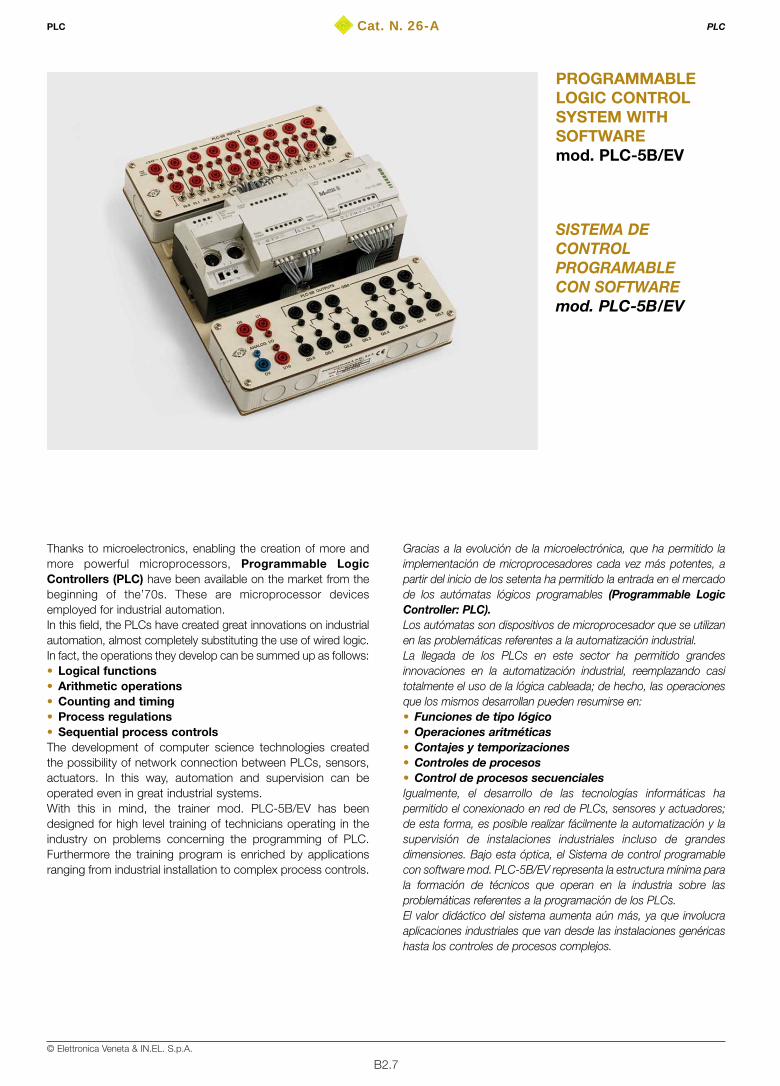
Thanks to microelectronics, enabling the creation of more andmore powerful microprocessors, Programmable LogicControllers (PLC) have been available on the market from thebeginning of the’70s. These are microprocessor devicesemployed for industrial automation. In this field, the PLCs have created great innovations on industrialautomation, almost completely substituting the use of wired logic.In fact, the operations they develop can be summed up as follows:• Logical functions • Arithmetic operations• Counting and timing • Process regulations • Sequential process controlsThe development of computer science technologies createdthe possibility of network connection between PLCs, sensors,actuators. In this way, automation and supervision can beoperated even in great industrial systems.With this in mind, the trainer mod. PLC-5B/EV has beendesigned for high level training of technicians operating in theindustry on problems concerning the programming of PLC.Furthermore the training program is enriched by applicationsranging from industrial installation to complex process controls.
Gracias a la evolución de la microelectrónica, que ha permitido laimplementación de microprocesadores cada vez más potentes, apartir del inicio de los setenta ha permitido la entrada en el mercadode los autómatas lógicos programables (Programmable LogicController: PLC).Los autómatas son dispositivos de microprocesador que se utilizanen las problemáticas referentes a la automatización industrial.La llegada de los PLCs en este sector ha permitido grandesinnovaciones en la automatización industrial, reemplazando casitotalmente el uso de la lógica cableada; de hecho, las operacionesque los mismos desarrollan pueden resumirse en:• Funciones de tipo lógico • Operaciones aritméticas• Contajes y temporizaciones• Controles de procesos • Control de procesos secuencialesIgualmente, el desarrollo de las tecnologías informáticas hapermitido el conexionado en red de PLCs, sensores y actuadores;de esta forma, es posible realizar fácilmente la automatización y lasupervisión de instalaciones industriales incluso de grandesdimensiones. Bajo esta óptica, el Sistema de control programablecon software mod. PLC-5B/EV representa la estructura mínima parala formación de técnicos que operan en la industria sobre lasproblemáticas referentes a la programación de los PLCs.El valor didáctico del sistema aumenta aún más, ya que involucraaplicaciones industriales que van desde las instalaciones genéricashasta los controles de procesos complejos.
B2.8© Elettronica Veneta & IN.EL. S.p.A.
PROGRAMMABLE LOGIC CONTROL SYSTEM WITHSOFTWARE mod. PLC-5B/EVThe programmable logic control trainer mod. PLC-5B/EV is thenecessary tool for the training of technicians operating in industryon the maintenance and the design of installation. Carried out withindustrial components, the trainer mod. PLC-5B/EV enables thedevelopment of a solid experimentation and a high content ofknowledge, on programming the PLC.The training program includes a wide range of applications:• Industrial installation• Robotics• Process controls The PLC on trainer mod. PLC-5B/EV is one of the most usedin the industry and provides many digital inputs and outputsby means of terminals with two diameters (Ø 4 mm and Ø 2mm) present on the front panel of the trainer. One of the digitalinputs can be used for fast counting, too. As concerns thedigital outputs, these are available as relay outputs. The logicstate of the digital inputs and outputs is displayed via LEDdiodes on the PLC.Two analog inputs (10 bit) and an analog output (12 bit) areavailable for exercises involving process control. With twopotentiometers inside the PLC, which can be adjusted withscrewdriver, you can regulate the voltage levels across theanalog inputs. In this way, no external power supply isnecessary for the generation of references.Two small front panels, upper and lower, not only report theterminals for the connections, but also the silk screen panel ofthe diagrams and the inner components of the equipment,complete with all names. This wide and clear vision of the system increases the teachingvalue, facilitating the layout of connections and thedevelopment of the exercises.The programming software in WIN 95/98 or superior, suppliedwith the system mod. PLC-5B/EV, enables the easydevelopment of programs of exercises with PLC in the mostused languages of industrial automation: AWL, KOP, FUP.The connection between Personal Computer and PLC is madevia the supplied serial interface cable RS-232. The development of the exercises is guided effectively by thetheoretical/experimental handbooks available with the trainer.
TRAINING PROGRAM The trainer mod. PLC-5B/EV enables the theoretical analysisand the experiments on the following main exercises:• PLC architecture• Processing of the instructions: cycle• Synchronous, asynchronous and priority cycles • Times of execution, cycle and reaction • Boolean Algebra • Basic programming in: AWL, KOP, FUP• Combinatory logic functions• Sequential logic functions • Addressing• Timers & counters
SISTEMA DE CONTROL PROGRAMABLECON SOFTWARE mod. PLC-5B/EVEl Sistema de control programable mod. PLC-5B/EV constituye elsoporte necesario para la formación de técnicos que operan en laindustria, tanto a nivel de mantenimiento de las instalaciones comoa nivel de diseño de las mismas. Está realizado con componentesindustriales y permite la realización de prácticas con un elevadocontenido de conocimientos sobre la programación de los PLCs. El programa de formación involucra en este contexto un amplioabanico de aplicaciones:• Instalaciones industriales• Robótica• Controles de procesosEl PLC a bordo del Sistema mod. PLC-5B/EV es uno de entre losmás difundidos en ámbito industrial y facilita una gran cantidad deentradas y salidas digitales asequibles a través de terminales condos diámetros (Ø 4 mm y Ø 2 mm) presentes en el panel delanterodel equipo. Una de las entradas digitales realiza también el contajerápido. Las salidas digitales están disponibles como salidas derelé. El estado lógico de las entradas y las salidas digitales sevisualiza por medio de diodos LEDs incorporados en el PLC.Dos entradas analógicas (10 bits) y una salida analógica (12 bits)permiten la realización de prácticas en las cuales se utiliza elcontrol de procesos. A través de dos potenciómetros rotativos,presentes en el PLC y regulables con un destornillador, es posibleajustar las tensiones en las entradas analógicas; de esta forma, seevita el uso de fuentes de alimentación externas para lageneración de referencias.Dos paneles delanteros pequeños, superior e inferior, incorporanademás de los terminales para las conexiones, también larepresentación sinóptica en serigrafía de los componentesinternos del equipo completa de todas las nomenclaturas.Esta clara visión del sistema aumenta el valor didáctico del mismo,facilitando la preparación de los conexionados y la realización delas prácticas.El software de programación en entorno WIN 95/98 o superiorproporcionado junto con el Sistema mod. PLC-5B/EV, permite unfácil desarrollo de programas para prácticas con el PLC en los másdifundidos lenguajes de automatización industrial: AWL, KOP, FUP.El conexionado entre el ordenador personal y el PLC se lleva a caboa través del cable de interfaz serie RS-232 en dotación. Por último, la realización de las prácticas es guiada con eficacia porlos manuales teórico-prácticos disponibles junto con el entrenador.
PROGRAMA DE FORMACIÓN El Sistema mod. PLC-5B/EV permite el análisis teórico y larealización de prácticas sobre los siguientes principales temas:• Arquitectura de un PLC• Procesamiento de las instrucciones: concepto de ciclo• Ciclos síncronos, asíncronos y con prioridades• Tiempos de ejecución, ciclo y reacción• Álgebra de Boole• Programación básica en los lenguajes: AWL, KOP, FUP• Funciones de lógica combinacional• Funciones de lógica secuencial• Direccionamientos• Temporizadores y contadores
PLC PLC

B2.9© Elettronica Veneta & IN.EL. S.p.A.
• Clock generators• Monostable circuits• Bistable circuits• Algebraic operations: sum, subtraction, and multiplication• BCD/binary conversions• Binary/BCD conversions• Structured programming techniques • Types of base data• Types of structured data • Function blocks which can be parameterized• Programmable function blocks• Typical applications
– Programmable systems simulator (mod. SSP/EV)– Industrial installation (mod. C/EV)– Automation of sliding gates (mod. MR/EV) – Electropneumatic installation (mod. D/EV)– Trainer for electropneumatic actuators (mod. EAT/EV)– Robomatic Trainer (mod. RMT/EV) – 3-floor lift (mod. HM400/EV)– Automation process with conveyor (mod. TSM-700/EV)– PID regulation of
Temperature process (mod. PUT-1/EV)Level and flow process ( mod. PUL-2/EV)Pressure process (mod. PUP-4/EV)Angular speed process (mod. PUV-6/EV)
• Communication of a PLC with PC: modalities• Diagnostics of the inputs and outputs • Diagnostics of the inner states• I/O forcing and inner variables• PLC networks
TECHNICAL SPECIFICATIONS• Light structure assembled on insulating material base• 24-Vdc output voltage for control of the digital inputs• 2 analog inputs in the 0..10 Vdc range• 1 analog output in the 0..10 Vdc range• Set up of the analog inputs with screwdriver regulation• 16 24-Vdc digital inputs of which 1 (I 0.0) for fast counting
(f=3 kHz)• 8 24-Vdc digital outputs• Safety terminals, standard Ø 4 mm and Ø 2 mm for
connection of the inputs and outputs to external devices• Digital outputs interfacing: with relay of 1 Aac/230 Vac and
1 Adc/24 Vdc range. Contacts without potential. • PLC characteristics
– Power supply: 24 Vdc– Clock calendar: yes– Buffer battery: yes, duration 5 years– Program and data inner memory: 32 kByte– Memory expansion: RAM 32 kByte – Typical time of cycle: 5 ms for 1 k instructions– Programming interface: RS-232– Network interface: RS-485– Bus: SuconetK– Operating mode: Master/Slave
• Generadores de reloj• Circuitos monoestables• Circuitos biestables• Operaciones algebraicas: suma, resta, multiplicación• Conversiones BCD/binario• Conversiones binario/BCD • Técnicas de programación estructurada• Tipos de datos básicos• Tipos de datos estructurados• Bloques función parametrizables• Bloques función programables• Aplicaciones típicas
– Simulador de sistemas programables (mod. SSP/EV)– Instalaciones eléctricas industriales (mod. C/EV)– Automatización de verjas corredizas (mod. MR/EV)– Instalaciones electroneumáticas (mod. D/EV)– Entrenador en actuadores electroneumáticos (mod. EAT/EV)– Brazo manipulador neumático (mod. RMT/EV)– Ascensor de 3 pisos (mod. HM400/EV)– Controles PID de
Proceso de temperatura (mod. PUT-1/EV)Proceso de nivel y caudal (mod. PUL-2/EV)Proceso de presión (mod. PUP-4/EV)Proceso de velocidad angular (mod. PUV-6/EV)
• Comunicación de un PLC con el PC: modalidades• Diagnóstico de entradas y salidas• Diagnóstico de los estados internos• Forzamiento E/S y variables internas• Redes del PLC
CARACTERÍSTICAS TÉCNICAS • Estructura ligera ensamblada sobre base realizada en
material aislante• Salida de tensión de 24 Vcc para gobierno de las entradas
digitales• 2 entradas analógicas en el margen 0..10 Vcc• 1 salida analógica en el margen 0..10 Vcc• Selección de las entradas analógicas con regulación
mediante destornillador• 16 entradas digitales de 24 Vcc, de las cuales 1 (I 0.0) para
contaje rápido (f=3 kHz) • 8 salidas digitales de 24 Vcc• Terminales de seguridad estándar Ø 4 mm y Ø 2 mm para
conexionado de las entradas y las salidas a dispositivos externos• Interfaz de las salidas digitales: con relé de alcance
1 Aca/230 Vca y 1 Acc/24 Vcc. Contactos libres de potencial• Características del PLC
– Alimentación: 24 Vcc– Reloj almanaque: sí– Batería tampón: sí, duración típ. 5 años– Memoria programa y datos interior: 32 kByte– Expansión de memoria: RAM 32 kByte – Tiempo de ciclo típico: 5 ms para 1 k instrucciones– Interfaz de programación: RS-232– Interfaz de red: RS-485– Bus: SuconetK– Modo de funcionamiento: Maestro/Esclavo– Ampliaciones (descentralizadas): máx. 8 participantes
PLC PLC

B2.10© Elettronica Veneta & IN.EL. S.p.A.
– Expandability (decentered): max. 8 participants– Digital inputs: 16 at 24 Vdc. Photocoupler insulation.
Positive polarity. Short response times (delay of 0.1 ms). Bitand Byte addressing
– Nominal current for each input: 6 mA – Fast counter inputs: 1 at the frequency of 3 kHz– Input state display: yes (LED diodes)– Digital outputs: 14 at 24 Vdc/0.5 A. Galvanic separation
from the CPU. Immunity against short-circuits andoverloads. Bit or Byte addressing
– Output state display: yes (green LED)– Parallel connection of the outputs: max. 4– Analog inputs: 2– A/D conversion: 10 bit (1024 increments)– Analog input voltage range: 0..10 Vdc– Input resistance: 20 kW– Potentiometers adjustable with screwdriver: 2 in the 0..10
Vdc range– Analog outputs: 1– D/A conversion: 12 bit (4096 increments)– Output voltage range: 0..10 Vdc– Operation/reset switch for mode selection: “HALT”, “RUN”
and “M-RESET RUN”• RS-232 cable for PC programming• Single-phase power supply cable
DIMENSIONS 250x300x90 mm
WEIGHT2 kg
POWER SUPPLY115/230 Vac ±10% – 50/60 Hz
SOFTWARE PLC programming • Software for the development of PLC programs in WIN 95/98
or superiors. AWL, KOP, FUP programming languages.
SUGGESTED ACCESSORIES I/O simulator which can be integrated into the PLCconsisting of:• Simulator for digital inputs with permanent and pulse state
switches• Ø 4-mm safety terminals and Ø 2-mm terminals for
connection of the inputs to external control devices • Ø 4-mm safety terminals and Ø 2-mm terminals for connection
of the outputs to actuator devices and/or external signalers.The I/O simulator is stored into 2 insulating material containers(separated I/O). The safety terminals are inserted into silkscreen panels for immediate detection of the specificdeveloped function, while the connection to the system mod.PLC-5B/EV is made via quick acting connectors.
THEORETICAL-EXPERIMENTAL HANDBOOKS• Theoretical-application handbook for equipment presentation
and guide to the exercises• PLC technical handbook with technical specifications, use
and maintenance, serial communication with PC
– Entradas digitales: 16 a 24 Vcc. Aislamiento confotoacoplador. Polaridad positiva. Tiempos de respuestabreves (retardo de 0,1 ms). Direccionamiento por bit y Byte
– Corriente nominal por cada entrada: 6 mA – Entradas contadores rápidos: 1 a frecuencia de 3 kHz– Visualización estado entradas: sí (diodos LED)– Salidas digitales: 14 a 24 Vcc/0,5 A. Separación galvánica
de la CPU. Inmunes contra la sobrecarga y el cortocircuito.Direccionamiento por bit o Byte
– Visualización estado salidas: sí (diodos LED)– Conexionado en paralelo de las salidas: máx. 4– Entradas analógicas: 2– Conversión A/D: 10 bits (1.024 incrementos)– Margen tensión entradas analógicas: 0..10 Vcc– Resistencia entrada: 20 kW– Potenciómetros regulables con destornillador: 2 en el
margen 0..10 Vcc– Salidas analógicas: 1– Conversión D/A: 12 bits (4.096 incrementos)– Margen tensión de salida: 0..10 Vcc– Preselector funcionamiento/reposición para la selección de
los modos: “HALT”, “RUN” y “M-RESET RUN”• Cable RS-232 para programación por medio de PC • Cable de alimentación monofásica
DIMENSIONES250x300x90 mm
PESO2 kg
ALIMENTACIÓN 115/230 Vca ±10% – 50/60 Hz
SOFTWARE Software de programación del PLC• Software para el desarrollo de programas con el PLC en
entorno WIN 95/98 o superior. Lenguajes: AWL, KOP, FUP.
ACCESORIOS RECOMENDADOS Simulador de E/S incorporable al PLC, constituido por:• Simulador para entradas digitales con interruptores de estado
permanente e impulsivo• Terminales de seguridad Ø 4 mm y Ø 2 mm para conexionado
de las entradas a dispositivos de mando exteriores• Terminales de seguridad Ø 4 mm y Ø 2 mm para conexionado de
las salidas a dispositivos actuadores y/o señalizadores exterioresEl simulador de E/S está contenido en dos estuches de materialaislante (E/S separadas). Los terminales de seguridad estáninsertados en paneles serigrafiados para el inmediatoreconocimiento de la función específica desarrollada, mientrasque el conexionado al Sistema mod. PLC-5B/EV se lleva a caboa través de conectores con acoplamiento rápido.
TEXTOS TEÓRICO-PRÁCTICOS • Manual teórico-aplicativo de presentación del equipo y guía
para las aplicaciones • Manual técnico del sistema con características técnicas, uso,
mantenimiento, comunicación serie con el ordenador personal
PLC PLC
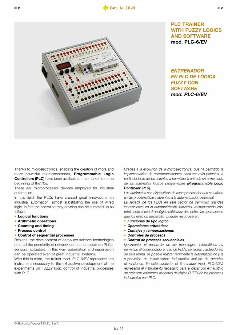
B2.11© Elettronica Veneta & IN.EL. S.p.A.
Cat. N. 26-BPLC PLC
ENTRENADOREN PLC DE LÓGICAFUZZY CONSOFTWAREmod. PLC-6/EV
PLC TRAINERWITH FUZZY LOGICSAND SOFTWAREmod. PLC-6/EV
Thanks to microelectronics, enabling the creation of more andmore powerful microprocessors, Programmable LogicControllers (PLC) have been available on the market from thebeginning of the’70s. These are microprocessor devices employed for industrialautomation.In this field, the PLCs have created great innovations onindustrial automation, almost substituting the use of wiredlogic. In fact the operation they develop can be summed up asfollows: • Logical functions • Arithmetic operations• Counting and timing• Process control• Control of sequential processes Besides, the development of computer science technologiescreated the possibility of network connection between PLCs,sensors, actuators. In this way, automation and supervisioncan be operated even of great industrial systems.With this in mind, the trainer mod. PLC-6/EV represents theinstrument necessary to the exhaustive development of theexperiments on FUZZY logic control of industrial processeswith PLC.
Gracias a la evolución de la microelectrónica, que ha permitido laimplementación de microprocesadores cada vez más potentes, apartir del inicio de los setenta ha permitido la entrada en el mercadode los autómatas lógicos programables (Programmable LogicController: PLC).Los autómatas son dispositivos de microprocesador que se utilizanen las problemáticas referentes a la automatización industrial.La llegada de los PLCs en este sector ha permitido grandesinnovaciones en la automatización industrial, reemplazando casitotalmente el uso de la lógica cableada; de hecho, las operacionesque los mismos desarrollan pueden resumirse en:• Funciones de tipo lógico • Operaciones aritméticas• Contajes y temporizaciones• Controles de procesos• Control de procesos secuencialesIgualmente, el desarrollo de las tecnologías informáticas hapermitido el conexionado en red de PLCs, sensores y actuadores;de esta forma, es posible realizar fácilmente la automatización y lasupervisión de instalaciones industriales incluso de grandesdimensiones. En este contexto, el Entrenador mod. PLC-6/EV,representa el instrumento necesario para el desarrollo exhaustivode prácticas referentes al control de lógica FUZZY de los procesosindustriales con PLC.

B2.12© Elettronica Veneta & IN.EL. S.p.A.
PLC TRAINER WITH FUZZY LOGIC AND SOFTWAREmod. PLC-6/EVThe trainer mod. PLC-6/EV has been designed and carried outwith industrial components and criteria to enable detailedexperiments on the subjects connected to industrial processcontrols with FUZZY logics. The controlled processes are the:• Temperature process• Pressure process Obviously, the characteristics of trainer mod. PLC-6/EV make ita useful tool for all the other typical PLC applications. The FUZZY control is carried out with a specific software,enabling to easily develop new applications, thanks to agraphical regulation approach. The FUZZY control softwareoperates inside the traditional PLC programming packet forwriting programs in the most used automation languages:AWL, KOP, FUP.The connection between Personal Computer and PLC is madevia the supplied serial interface cable RS-232. The PLC of trainer mod. PLC-6/EV is one of the most used inthe industry. It provides many digital inputs and outputsaccessible by means of the terminals present on the trainerfront panel. Three digital channels are employed for fast counting (50 kHz)and can be used in the position control with encoder. Asconcerns the digital outputs, these are available as relayoutputs. The logic state of the digital inputs and outputs isdisplayed via LED diodes on the PLC.Two analog inputs (10 bit) and an analog output (12 bit) areavailable for exercises involving process control. With tworotating potentiometers and an inner stabilizer, you can adjustthe voltage levels at the analog inputs. In this way, no externalpower supply is necessary for the generation of references.The front panel of the trainer mod. PLC-6/EV shows the silkscreen panel of the diagrams and the inner components of theequipment, complete with any name. This wide and clear visionof the system increases the teaching value, facilitating thelayout of connections and the development of the exercises.A 3 1/2 -digit digital voltmeter displays the voltage across theanalog inputs and outputs according to the position of therotating switch. At last, the development of the exercises is guided effectivelyby the theoretical/experimental handbooks available with thetrainer.
TRAINING PROGRAM The trainer mod. PLC-6/EV enables the theoretical analysis andthe experiments on the following main exercises:• PLC architecture• Processing of the instructions: cycle• Data inner representation• Boolean Algebra • Basic programming in: AWL, KOP, FUP• Combinatory logic functions• Sequential logic functions • Timers & counters• Clock generators• Shift registers• Algebraic operations: sum, subtraction, and multiplication• Structured programming techniques
ENTRENADOR EN PLC DE LÓGICA FUZZY CON SOFTWAREmod. PLC-6/EVEl Entrenador mod. PLC-6/EV ha sido diseñado y fabricado concomponentes y criterios industriales para permitir la realización deprácticas detalladas sobre los temas relacionados con el controlde los procesos industriales con lógica FUZZY.Los procesos controlados son:• Proceso de temperatura• Proceso de presiónNaturalmente, el Entrenador mod. PLC-6/EV, por sus características,puede utilizarse en todas las demás aplicaciones típicas de los PLCs.El control FUZZY se realiza por medio de un software específicoque permite un fácil desarrollo de nuevas aplicaciones, gracias aun enfoque gráfico de la regulación. El software de control FUZZYfunciona en el interior del paquete tradicional de programación delPLC para la escritura de programas con los lenguajes paraautomatización más difundidos: AWL, KOP, FUP.El conexionado entre el ordenador personal y el PLC se realiza através del cable de interfaz serie RS-232 en dotación. El PLC presente a bordo del Entrenador mod. PLC-6/EV es unode entre los más difundidos en ámbito industrial y facilita una granvariedad de entradas y salidas digitales asequibles a través deconectores presentes en el panel delantero del equipo. Trescanales digitales tienen la función de contaje rápido (50 kHz) ypueden utilizarse en el control de posición con codificador. Lassalidas digitales están disponibles como salidas de relé. El estadológico de las entradas y las salidas digitales se visualiza por mediode diodos LEDs incorporados en el PLC.Dos entradas analógicas (10 bits) y una salida analógica (12 bits)permiten la realización de prácticas que utilizan el control deprocesos. Es posible regular el nivel de las tensiones en lasentradas analógicas a través de dos potenciómetros rotativos y unestabilizador interno; de esta forma, se evita el uso de fuentes dealimentación externas para la generación de referencias.El panel delantero del Entrenador mod. PLC-6/EV lleva larepresentación sinóptica serigrafiada de los esquemas y loscomponentes internos del equipo, completa de todas lasnomenclaturas. Esta amplia y clara visión del sistema aumenta elvalor didáctico del mismo, facilitando la preparación de losconexionados y la realización de las prácticas.Un voltímetro digital de 3 1/2 cifras visualiza la tensión de lasentradas analógicas o la salida analógica, en base a la posición deun selector rotativo.Por último, la realización de las prácticas es guiada con eficacia porlos manuales teórico-prácticos disponibles junto con el entrenador.
PROGRAMA DE FORMACIÓN El Entrenador mod. PLC-6/EV permite el análisis teórico y larealización de prácticas sobre los siguientes principales temas:• Arquitectura de un PLC• Procesamiento de las instrucciones: concepto de ciclo• Representación interna de los datos• Álgebra de Boole• Programación básica en los lenguajes: AWL, KOP, FUP• Funciones de lógica combinacional• Funciones de lógica secuencial• Temporizadores y contadores• Generadores de reloj• Registros de desplazamiento• Operaciones algebraicas: suma, resta, multiplicación• Técnicas de programación estructurada
PLC PLC

B2.13© Elettronica Veneta & IN.EL. S.p.A.
• Types of base data• Types of structured data • Function blocks which can be parameterized• Programmable function blocks• FUZZY logics
– Fuzzy sets– Member function– Rule base & data base– Inference engines– Fuzzification methods – Defuzzification methods– Fuzzy controllers
• Typical applications of FUZZY control– Temperature control ( mod. PUT-1/EV)– Pressure control (mod. PUP-4/EV)
• Typical PLC applications– Programmable systems simulator (mod. SSP/EV)– Industrial installation (mod. C/EV)– Automation of sliding gates (mod. MR/EV) – Electropneumatic installation (mod. D/EV)– Trainer for electropneumatic actuators (mod. EAT/EV)– Robomatic Trainer (mod. RMT/EV) – 3-floor lift (mod. HM400/EV)– Automation process with conveyor (mod. TSM-700/EV)– PID regulation of
Temperature process (mod. PUT-1/EV)Pressure process (mod. PUP-4/EV)Level and flow process ( mod. PUL-2/EV)Angular speed process (mod. PUV-6/EV)
• Communication of a PLC with PC: modalities• Diagnostics of the inputs and outputs • Diagnostics of the inner states• I/O forcing and inner variables• PLC networks
TECHNICAL SPECIFICATIONS • Sheet steel container, chemically treated and painted with
epoxy paint • Side handles to easily move the equipment in the laboratory• Front panel, in insulating material, with silk screen
representation of the diagrams and inner components of theequipment
• 24 Vdc / 3 A power supply for control of the digital inputs andoutputs. With electronic protection against short-circuits andoverloads
• 24 Vac / 3 A power supply for relay output control. With fuseprotection against overcurrents
• 1 3 1/2 -digit digital voltmeter for measurement of the voltagepresent across the inputs or the analog output. 0.1 Vdcresolution
• 1 rotating switch for voltmeter input selection• 2 analog inputs V / I: ±10 Vdc, 0..20 mA • 1 analog output V / I: ±10 Vdc, 0..20 mA • 2 rotating potentiometers for setting up analog references • Inner voltage reference obtained via 24-Vdc inner stabilizer• 16 24-Vdc digital inputs of which 3 for fast counting (f=50 kHz)
• Tipos de datos básicos• Tipos de datos estructurados• Bloques función parametrizables• Bloques función programables• La lógica FUZZY
– Fuzzy sets– Member function– Rule base & data base– Motores inferenciales– Métodos de fuzzificación– Métodos de desfuzzificación– Autómatas Fuzzy
• Aplicaciones típicas del autómata FUZZY– Control de temperatura (mod. PUT-1/EV)– Control de presión (mod. PUP-4/EV)
• Aplicaciones típicas genéricas del PLC– Simulador de sistemas programables (mod. SSP/EV)– Instalaciones eléctricas industriales (mod. C/EV)– Automatización de verjas corredizas (mod. MR/EV)– Instalaciones electroneumáticas (mod. D/EV)– Entrenador en actuadores electroneumáticos (mod. EAT/EV)– Brazo manipulador neumático (mod. RMT/EV)– Ascensor de 3 pisos (mod. HM400/EV)– Proceso de automatización con transportador (mod. TSM-700/EV)– Controles PID
Proceso de temperatura (mod. PUT-1/EV)Proceso de presión (mod. PUP-4/EV)Proceso de nivel y caudal (mod. PUL-2/EV)Proceso de velocidad angular (mod. PUV-6/EV)
• Comunicación de un PLC con el PC: modalidades• Diagnóstico de entradas y salidas• Diagnóstico de los estados internos• Forzamiento E/S y variables internas• Redes del PLC
CARACTERÍSTICAS TÉCNICAS• Estructura en chapa de acero, tratada químicamente y pintada
con barniz epoxi• Asideros laterales non sobresalientes para un fácil
desplazamiento en el laboratorio• Panel delantero, en material aislante, con representación
sinóptica y serigrafiada de los esquemas y los componentespuestos en el interior del equipo
• Fuente de alimentación 24 Vcc/3 A para el gobierno de lasentradas y las salidas digitales. Incluida la protección electrónicacontra las sobrecargas y los cortocircuitos
• Fuente de alimentación 24 Vca/3 A para el mando de las salidasde relé. Incluida protección por fusible contra las sobrecorrientes
• Voltímetro digital de 3 1/2 dígitos para la medida de la tensiónpresente en las entradas analógicas o en la salida analógica.Resolución 0,1 Vcc
• Selector rotativo para la selección de la entrada del voltímetro• 2 entradas analógicas en el margen 0..10 Vcc• 1 salida analógica en el margen 0..10 Vcc• 2 potenciómetros rotativos para la selección de referencias analógicas• Referencia de tensión interna obtenida a través de estabilizador
interior de 24 Vcc• 16 entradas digitales a 24 Vcc, de las cuales 3 para contaje
rápido (f=50 kHz)
PLC PLC

B2.14© Elettronica Veneta & IN.EL. S.p.A.
• Digital input simulator with permanent and pulse state switches• 14 24-Vdc digital outputs • Safety terminals, standard Ø 4 mm and Ø 2 mm, for
connection of the inputs and outputs to external devices• Digital outputs interfacing
– with relay ranging between 10 Aac/2 Adc– transistor for fast applications
• PLC characteristics: – Power supply: 24 Vdc– Clock calendar: yes– Buffer battery: yes, duration 5 years– Program and data inner memory: 512 kByte– Memory expansion: 1 MByte – Typical time of cycle: 0.5 ms for 1-k instructions– Programming interface: RS-232– Network interface: RS-485– Programme and inner data memory: 512 kByte– Bus: SuconetK– Operating mode: Master/Slave– Expandability (decentered): max. 30 participants– Digital inputs: 16 at 24 Vdc. Photocoupler insulation.
Positive polarity. Short response times (delay of 0.1 ms). Bitand Byte addressing
– Fast counter inputs: 1 at the frequency of 50kHz– Input state display: yes (LED diodes)– Digital outputs: 14 at 24 Vdc/0.5 A. Galvanic separation
from the CPU. Immunity against short-circuits andoverloads. Bit or Byte addressing.
– Output state display: yes (LED diodes)– Parallel connection of the outputs: max. 4– Analog inputs: 2– A/D conversion: 10 bit (1024 increments)– Range of the analog input voltage: 0..10 Vdc– Potentiometers adjustable with screwdriver: 2 in the 0..10
Vdc range– Analog outputs: 1– D/A conversion: 12 bit (4096 increments)– Output voltage range: 0..10 Vdc– Operation/reset switch for mode selection: “HALT”, “RUN”
and “M-RESET RUN”• RS-232 cable for PC programming• Single-phase power supply cable
DIMENSIONS: 415x400x150 mm
WEIGHT: 10 kg
POWER SUPPLY115/230 Vac ±10% – 50/60 Hz
SOFTWARE PROGRAMMINGSoftware for PLC programming• Software for the development of PLC programs in WIN 95/98
or superiors. AWL, KOP, FUP programming languages. FUZZY control software• Industrial software packet, provided with graphic interface
necessary to the development of process controls withFUZZY logics; development ambient WIN 95/98 or superior.
THEORETICAL-EXPERIMENTAL HANDBOOKS • Theoretical-application handbook for equipment presentation
and guide to the exercises• PLC technical handbook with technical specifications, use
and maintenance, serial communication with PC
• Simulador para las entradas digitales con interruptores deestado permanente e impulsivo
• 14 salidas digitales a 24 Vcc• Terminales de seguridad estándar Ø 4 mm y Ø 2 mm para
conexionado de las entradas y las salidas a dispositivos exteriores• Interfaz de las salidas digitales:
– con relé de alcance 10 Aca/2 Acc– transistor para aplicaciones rápidas
• Características del PLC– Alimentación: 24 Vcc– Reloj almanaque: sí– Batería tampón: sí, duración típ. 5 años– Memoria programa y datos interior: 512 kByte– Expansión de memoria: 1 Mbyte– Tiempo de ciclo típico: 0,5 ms para 1 k instrucciones– Interfaz de programación: RS-232– Interfaz de red: RS-485– Bus: SuconetK– Modo de funcionamiento: Maestro/Esclavo– Ampliaciones (descentralizadas): máx. 30 participantes– Entradas digitales: 16 a 24 Vcc. Aislamiento a fotoacoplador.
Polaridad positiva. Tiempos de respuesta breves (retardo de0,1 ms). Direccionamiento por bit y Byte
– Entradas contadores rápidos: 3 a frecuencia de 50 kHz– Visualización estado entradas: sí (diodos LED)– Salidas digitales: 14 a 24 Vcc/0,5 A. Separación galvánica de
la CPU. Inmunes contra la sobrecarga y el cortocircuito.Direccionamiento por bit o Byte
– Visualización estado salidas: sí (diodos LED)– Conexionado en paralelo de las salidas: máx. 4– Entradas analógicas: 2– Conversión A/D: 10 bits (1.024 incrementos)– Margen tensión entradas analógicas: 0..10 Vcc– Potenciómetros regulables con destornillador: 2 en el margen
0..10 Vcc– Salidas analógicas: 1– Conversión D/A: 12 bits (4.096 incrementos)– Margen tensión salida: 0..10 Vcc– Preselector funcionamiento/reposición para selección de los
modos: “HALT”, “RUN” y “M-RESET RUN”• Cable RS-232 para programación mediante PC • Cable de alimentación monofásica
DIMENSIONES: 415x400x150 mm
PESO: 10 kg
ALIMENTACIÓN115/230 Vca ±10% – 50/60 Hz
SOFTWARESoftware de programación del PLC• Software para el desarrollo de programas PLC en entorno WIN
95/98 o superior. Lenguajes AWL, KOP, FUP.Software de control FUZZY • Software industrial, provisto del interfaz gráfico necesario para el
desarrollo de controles de procesos con lógica FUZZY; entornode desarrollo WIN 95/98 o superior.
TEXTOS TEÓRICO-PRÁCTICOS• Manual teórico-aplicativo de presentación del equipo y guía
para las aplicaciones • Manual técnico del autómata con características técnicas, uso,
mantenimiento, comunicación serie con el ordenador personal
PLC PLC

B2.15© Elettronica Veneta & IN.EL. S.p.A.
Cat. N. 26-BPLC PLC
ENTRENADOREN PLC CONSOFTWARE mod. PLC-7/EV
PLC TRAINERWITH SOFTWAREmod. PLC-7/EV
Thanks to microelectronics, enabling the creation of more andmore powerful microprocessors, Programmable LogicControllers (PLC) have been available on the market from thebeginning of the’70s. These are microprocessor devices employed for industrialautomation.In this field, the PLCs have created great innovations onindustrial automation, almost substituting the use of wired logic.In fact the operation they develop can be summed up as follows:• Logical functions • Arithmetic operations• Counting and timing• PID process regulations • Control of sequential processes Besides, the development of computer science technologiescreated the possibility of network connection between PLCs,sensors, actuators. In this way, automation and supervision canbe operated even of great industrial systems.With this in mind, the trainer mod. PLC-7/EV has been designedfor high level training of technicians operating in the industry onproblems concerning industrial process controls. The trainingprogram is enriched by applications ranging from industrialinstallation to robotics, from simulated systems to real industrialprocess controls.On this purpose the trainer mod. PLC-7/EV, offers the possibilityto carry out regulation algorithms: PID standard, PID Self Tuning.Obviously the trainer can be used also in those applications oflower level connected to sequential process control.
PLC TRAINER WITH SOFTWARE mod. PLC-7/EVInside a laboratory for automation technologies, the trainermod. PLC-7/EV is the necessary tool for high level trainingof technicians operating in modern processes industry.Carried out with industrial components, the trainer mod.PLC-7/EV enables the development of a solidexperimentation with a high content of knowledge, on
Gracias a la evolución de la microelectrónica, que ha permitido laimplementación de microprocesadores cada vez más potentes, apartir del inicio de los setenta ha permitido la entrada en el mercadode los autómatas lógicos programables (Programmable LogicController: PLC).Los autómatas son dispositivos de microprocesador que se utilizan enlas problemáticas referentes a la automatización industrial.La llegada de los PLCs en este sector ha permitido grandesinnovaciones en la automatización industrial, reemplazando casitotalmente el uso de la lógica cableada; de hecho, las operaciones quelos mismos desarrollan pueden resumirse en:• Funciones lógicas• Operaciones aritméticas• Contajes y temporizaciones• Controles de procesos PID • Control de procesos secuencialesIgualmente, el desarrollo de las tecnologías informáticas ha permitido elconexionado en red de PLCs, sensores y actuadores; de esta forma, esposible realizar fácilmente la automatización y la supervisión deinstalaciones industriales incluso de grandes dimensiones.En este contexto, el Entrenador mod. PLC-7/EV ha sido diseñado yrealizado para la formación a nivel sumamente avanzado de técnicosque operan sobre todo en el ámbito de los controles de procesosindustriales. A tal efecto, el Entrenador mod. PLC-7/EV ofrece laposibilidad de realizar algoritmos de regulación: PID estándar, PID SelfTuning. Naturalmente, el entrenador puede utilizarse también en todaslas aplicaciones de nivel inferior relacionadas con el control de procesossecuenciales.
ENTRENADOR EN PLC CON SOFTWARE mod. PLC-7/EVEn el interior de un laboratorio para las tecnologías de la automatización,el Entrenador mod. PLC-7/EV representa el instrumento necesario parala formación de nivel sumamente elevado de técnicos que operan en lamoderna industria de los procesos.El Entrenador mod. PLC-7/EV está realizado totalmente concomponentes industriales y permite la realización de prácticas
B2.16© Elettronica Veneta & IN.EL. S.p.A.
PLC programming and the solution of more complexproblems related to automation.The training program includes a wide range of applications:• Industrial installation• Robotics• Automation with conveyor• Process controls with PID PID, PID Self Tuning techniquesThe PLC of trainer mod. PLC-7/EV is one of the most used in theindustry. It provides many digital inputs and outputs accessibleby means of terminals of two diameters (Ø 4 mm and Ø 2 mm)present on the front panel of the trainer. Four special digital inputs are used for fast counting, process alarms,frequency measurement and positioning. As concerns the digitaloutputs, these are available as relay and transistor outputs for allthose applications needing quicker times. The logic state of thedigital inputs and outputs is displayed via LED diodes on the PLC.4 analog inputs (11 bit + sign) and an analog output (11 bit + sign)are available for exercises involving process control. With fourrotating potentiometers and an inner stabilizer, you can adjust thevoltage levels at the analog inputs. In this way, no external powersupply is necessary for the generation of references.The front panel of the trainer mod. PLC-7/EV shows the silkscreen panel of the diagrams and the inner components of theequipment, complete with every name. This wide and clear visionof the system increases the teaching value, facilitating the layoutof connections and the development of the exercises.A 3 1/2 -digit digital voltmeter displays the voltage across the analoginputs and outputs according to the position of the rotating switch.The programming software in WIN 95/98 or superior enables theeasy development of exercise programs with PLC in the most usedlanguages of industrial automation: AWL, KOP, FUP.The connection between Personal Computer and PLC is madevia the supplied serial interface cable RS-232 and PC adapter. At last, the development of the exercises is guided effectively bythe theoretical/experimental handbooks available with the trainer.
TRAINING PROGRAMThe trainer mod. PLC-7/EV enables the theoretical analysis andthe experiments on the following main exercises:• PLC architecture• Processing of the instructions: cycle• Synchronous, asynchronous and priority cycles • Times of execution, cycle and reaction • Boolean Algebra • Basic programming in: AWL, KOP, FUP• Combinatory logic functions• Sequential logic functions • Addressing• Timers & counters• Clock generators• Monostable, bistable circuits• Algebraic operations: sum, subtraction, and multiplication• Trigonometric, exponential, logarithmic functions• BCD/binary conversions• Binary/BCD conversions• Structured programming techniques
detalladas y con un elevado contenido de conocimientos sobre laprogramación de los PLCs, así como la solución de las más complejasproblemáticas relacionadas con la automatización. El programa de formación involucra en este contexto un amplio abanicode aplicaciones:• Instalaciones eléctricas industriales• Robótica• Automatización con transportador• Controles de procesos con técnicas PID, PID Self Tuning.El PLC a bordo del Entrenador PLC-7/EV es uno de entre los másdifundidos en ámbito industrial y facilita una gran cantidad de entradasy salidas digitales, asequibles a través de terminales con dos diámetros(Ø 4 mm y Ø 2 mm) y presentes en el panel delantero del entrenador. Cuatro entradas digitales especiales tienen la función de contaje rápido,alarmas de proceso, medida de frecuencia y posicionamiento. Lassalidas digitales están disponibles como salidas de relé o transistor paratodas aquellas aplicaciones que requieran tiempos más rápidos. Elestado lógico de las entradas y las salidas digitales se visualiza pormedio de diodos LEDs incorporados en el PLC.Cuatro entradas analógicas (11 bits + signo) y una salida analógica (11bits + signo) permiten la realización de prácticas en las cuales se utilizael control de procesos. Es posible regular el nivel de las tensiones o lascorrientes en las entradas analógicas a través de cuatro potenciómetrosrotativos y un estabilizador interno; de esta forma, se evita el uso defuentes de alimentación externas para la generación de referencias.El panel delantero del Entrenador mod. PLC-7/EV lleva larepresentación sinóptica serigrafiada de los esquemas y loscomponentes internos del equipo, completa de todas lasnomenclaturas. Esta amplia y clara visión del sistema aumenta el valordidáctico del mismo, facilitando la preparación de los conexionados y larealización de las prácticas. Un voltímetro digital de 3 1/2 cifras visualizala tensión de las entradas analógicas o la salida analógica, en base ala posición de un selector rotativo.El software de programación en entorno WIN 95/98 o superior permiteel desarrollo de programas de prácticas con el PLC en los másdifundidos lenguajes de la automatización industrial: AWL, KOP, FUPsegún la norma IEC 61131-3. El conexionado entre el ordenadorpersonal y el PLC se realiza por medio del cable de interfaz serie RS-232y convertidor para comunicación por ordenador personal en dotación.Por último, la realización de las prácticas es guiada con eficacia por losmanuales teórico-prácticos disponibles junto con el entrenador.
PROGRAMA DE FORMACIÓN El Entrenador mod. PLC-7/EV permite el análisis teórico y larealización de prácticas sobre los siguientes principales temas:• Arquitectura de un PLC• Procesamiento de las instrucciones: concepto de ciclo• Ciclos síncronos, asíncronos y con prioridades • Tiempos de ejecución, ciclo y reacción• Álgebra de Boole• Programación básica en los lenguajes: AWL, KOP, FUP• Funciones de lógica combinacional• Funciones de lógica secuencial• Direccionamientos • Temporizadores y contadores• Generadores de reloj• Circuitos monoestables, biestables• Operaciones algebraicas: suma, resta, multiplicación, división• Funciones trigonométricas, exponenciales, logarítmicas • Conversiones BCD/binario• Conversiones binario/BCD • Técnicas de programación estructurada
PLC PLC
B2.17© Elettronica Veneta & IN.EL. S.p.A.
• Types of base and structured data• Programming of functions, function blocks, data blocks• Standard and system functions • Fast counting integrated functions, frequency measurement,
positioning• Process interrupt control• Programming and use of the industrial user panel mod. IOP• Typical applications
– Programmable systems simulator (mod. SSP/EV)– Industrial installation (mod. C/EV)– Automation of sliding gates (mod. MR/EV) – Electropneumatic installation (mod. D/EV)– Trainer for electropneumatic actuators (mod. EAT/EV)– Robomatic Trainer (mod. RMT/EV) – 3-floor lift (mod. HM400/EV)– Automation process with conveyor (mod. TSM-700/EV)– PID regulations
Temperature process (mod. PUT-1/EV)Pressure process (mod. PUP-4/EV)Level and flow process ( mod. PUL-2/EV)Angular speed process (mod. PUV-6/EV)
• Communication of a PLC with PC: modalities• Diagnostics of the inputs and outputs • Diagnostics of the inner states• I/O forcing and inner variables• PLC networks (Master/Slave)
TECHNICAL SPECIFICATIONS • Sheet steel container, chemically treated and painted with
epoxy paint • Side handles to easily move the equipment in the laboratory• Front panel, in insulating material, with silk screen
representation of the diagrams and inner components of theequipment
• 24 Vdc / 3 A power supply for control of the digital inputs andoutputs. With electronic protection against short-circuits andoverloads
• 24 Vac / 3 A power supply for relay output control. With fuseprotection against overloads
• 1 3 1/2 -digit digital voltmeter for measurement of the voltagepresent across the inputs or the analog output. 0.1Vdcresolution
• 1 rotating switch for voltmeter input selection• 4 V / I analog inputs: ±10 Vdc, 0..20 mA • 1 V / I analog output: ±10 Vdc, 0..20 mA • 4 rotating potentiometers for setting up analog references in
the range of 0..10 Vdc • Inner voltage reference obtained via 24 Vdc inner stabilizer• 16 standard digital inputs• 4 special digital inputs for fast counting, process alarms,
frequency measurements, positioning• Digital input simulator with permanent and pulse state
switches • 16 24-Vdc digital outputs • Safety terminals, standard Ø 4 mm and Ø 2 mm, for connection
of the inputs and outputs to external devices• Digital outputs interfacing
– With relay ranging between 10 Aac/2 Adc– Transistor for fast applications
• Tipos de datos básicos y estructurados• Programación de funciones, bloques función, bloques datos• Funciones estándar y de sistema • Funciones integradas de contaje rápido, medida de frecuencia,
posicionamiento• Gobierno de interrupciones de procesos• Programación y uso del panel operador industrial mod. IOP/EV • Aplicaciones típicas
– Simulador de sistemas programables (mod. SSP/EV)– Instalaciones eléctricas industriales (mod. C/EV)– Automatización de verjas corredizas (mod. MR/EV)– Instalaciones electroneumáticas (mod. D/EV)– Entrenador en actuadores electroneumáticos (mod. EAT/EV)– Brazo manipulador neumático (mod. RMT/EV)– Ascensor de 3 pisos (mod. HM400/EV)– Proceso de automatización con transportador (mod. TSM-700/EV)– Controles PID
Proceso de temperatura (mod. PUT-1/EV)Proceso de presión (mod. PUP-4/EV)Proceso de nivel y caudal (mod. PUL-2/EV)Proceso de velocidad angular (mod. PUV-6/EV)
• Comunicación de un PLC con el PC: modalidades• Diagnóstico de entradas y salidas• Diagnóstico de los estados internos• Forzamiento E/S y variables internas• Redes del PLC (Maestro/Esclavo)
CARACTERÍSTICAS TÉCNICAS• Estructura en chapa de acero, tratada químicamente y pintada con
barniz epoxi • Asideros laterales no sobresalientes para un fácil desplazamiento en
el laboratorio• Panel delantero, en material aislante, con representación sinóptica y
serigrafiada de los esquemas y los componentes puestos en elinterior del equipo
• Fuente de alimentación 24 Vcc/3 A para el gobierno de las entradasy las salidas digitales. Incluida la protección electrónica contra lassobrecargas y los cortocircuitos
• Fuente de alimentación 24 Vca/3 A para el mando de las salidas derelé. Incluida protección por fusible contra las sobrecorrientes
• Voltímetro digital de 3 1/2 dígitos para la medida de la tensión presenteen las entradas analógicas o en la salida analógica. Resolución 0,1 Vcc
• Selector rotativo para la selección de la entrada del voltímetro• 4 entradas analógicas V/I: ±10 Vcc, 0..20 mA• 1 salida analógica V/I: ±10 Vcc, 0..20 mA• 4 potenciómetros rotativos para la selección de referencias
analógicas de tensión en el margen 0..10 Vcc• Referencia de tensión interior obtenida a través de estabilizador
interior de 24 Vcc• 16 entradas digitales estándar• 4 entradas digitales especiales para contaje rápido, alarmas de
proceso, medidas de frecuencia, posicionamiento• Simulador para las entradas digitales con interruptores de estado
permanente e impulsivo• 16 salidas digitales de 24 Vcc• Terminales de seguridad estándar Ø 4 mm y Ø 2 mm para conexión
de las E/S a dispositivos externos• Interfaz de las salidas digitales
– Con relé de alcance 10 Aca/2 Acc– Transistor para aplicaciones rápidas
PLC PLC

B2.18© Elettronica Veneta & IN.EL. S.p.A.
• PLC characteristics – Power supply: 24 Vdc– Calendar: yes– Buffer battery: yes, duration 5 years– Work memory: 32 kByte– Data memory: 40 kByte RAM– Speed: 0.3 ms for 1000 binary instructions– Programming interface: RS-485– Network interface: RS-485– Communication: MPI (Multi Point Interface) – Operating mode: Master/Slave PPI – Participants: max. 32 with repeater– Digital inputs: 16 at 24 Vdc; potential separation into group of
4; protection from bias inversion. Bit , byte, word addressing– Special digital inputs: 4 with fast counting functions (10 kHz),
process alarm, frequency-meter, positioning (1 channel) – Input state display: yes ( green LED)– Digital outputs: 16 at 24 Vdc / 0.5 A. Galvanic separation from
the CPU into group of 8. Immunity against short-circuits. Bit,byte, word addressing.
– Output state display: yes (LED diodes)– Parallel connection of the outputs: max. 2 of the same group– Analog inputs: 4 voltage/current– A/D conversion : 11 bit + sign– Analog input voltage range: ±10 Vdc– Analog input current range: ±20 mA– Analog outputs: 1– D/A conversion resolution : 11 bit + sign– Analog input voltage range: ±10 Vdc– Analog input current: range: ±20 mA– Operating mode switch: “STOP” , “RUN” , “RUN-P”, “MRES”.
• Interface RS-232/ MPI• RS-232 cable for PC programming• Single-phase power supply cable
DIMENSIONS: 415x400x150 mm
WEIGHT: 10 kg
POWER SUPPLY: 115/230 Vac ±10% – 50/60 Hz
SOFTWARESoftware for PLC programming• Software for the development of PLC programs in WIN 95/98 or
superiors. AWL, KOP, FUP programming languages.
OPTIONAL SOFTWAREPID SELF-TUNING control software• Industrial software packet for PID control with auto-tuning
characteristics for calibration of the P, I, D parametersSupervision software mod. SVS-1/EV• Powerful industrial software packet, provided with graphic
pages suggested for the development of supervision andservice exercises. Windows programming ambient
THEORETICAL-EXPERIMENTAL HANDBOOKS• Theoretical-application handbook for equipment presentation
and guide to the exercises• PLC technical handbook with technical specifications, use and
maintenance, serial communication with PC
• Características del PLC– Alimentación: 24 Vcc– Reloj hardware: sí– Batería tampón: sí, duración típ. 5 años– Memoria de operación: 32 kByte– Memoria de carga: 40 kByte RAM– Velocidad: 0,3 ms para 1000 instrucciones binarias– Interfaz de programación: RS-485– Interfaz de red: RS-485– Comunicación: MPI (Multi Point Interface) – Modo de funcionamiento: Maestro/Esclavo– N° participantes: máx. 32 con repetidor– Entradas digitales: 16 a 24 Vcc; separación de potencial por
grupos de cuatro; protección contra la inversión de polaridad.Direccionamiento por bit, byte y word
– Entradas digitales especiales: 4 con funciones de: contaje rápido (10kHz), alarma de proceso, frecuencímetro, posicionamiento (1 canal)
– Visualización estado entradas: sí (LED verde)– Salidas digitales: 16 a 24 Vcc/0,5 A; separación galvánica de la
CPU por grupos de 8; inmunidad contra el cortocircuito.Direccionamiento por bit, byte y word
– Visualización estado salidas: sí (diodos LED)– Conexionado en paralelo de las salidas: máx. 2 del mismo grupo– Entradas analógicas: 4 tensión/corriente – Resolución conversión A/D: 11 bits + signo– Margen tensión entradas analógicas: ±10 Vcc– Margen corriente entradas analógicas: ±20 mA– Salidas analógicas: 1– Resolución conversión D/A: 11 bits + signo– Margen tensión salida analógica: ±10 Vcc– Margen corriente salida analógica: ±20 mA– Selector con llave de los modos de funcionamiento: “STOP”,
“RUN”, “RUN-P”, “MRES”• Interfaz RS-232/MPI• Cable RS232 de conexión a PC • Cable de alimentación monofásica
DIMENSIONES: 415x400x150 mm
PESO: 10 kg
ALIMENTACIÓN: 115/230 Vca ±10% 50/60 Hz
SOFTWARE Software de programación del PLC• Software para el desarrollo de programas PLC en entorno WIN
95/98 o superior. Lenguajes AWL, KOP, FUP.
SOFTWARES OPCIONALESSoftware de control PID SELF-TUNING• Software industrial de control PID con características de auto-
tuning para la calibración de los parámetros P, I, D.Software de supervisión mod. SVS-1/EV• Potente software industrial, de páginas gráficas, recomendado para
la realización de prácticas de supervisión y servicio. Entorno deprogramación Windows.
TEXTOS TEÓRICO-PRÁCTICOS• Manual teórico-aplicativo de presentación del equipo y guía para las
aplicaciones• Manual técnico del autómata con características técnicas, uso,
mantenimiento, comunicación serie con el ordenador personal
PLC PLC

B2.19© Elettronica Veneta & IN.EL. S.p.A.
Cat. N. 26-BPLC PLC
ENTRENADOR EN PLCCON SOFTWARE mod. PLC-8/EV
PLC TRAINERWITH SOFTWAREmod. PLC-8/EV
Thanks to microelectronics, enabling the creation of more andmore powerful microprocessors, Programmable LogicControllers (PLC) have been available on the market from thebeginning of the’70s. These are microprocessor devices employed for industrialautomation.In this field, the PLCs have created great innovations onindustrial automation, almost substituting the use of wiredlogics. In fact the operation they develop can be summed upas follows: • Logical functions • Arithmetic operations• Counting and timing• Process regulations• Control of sequential processes Besides, the development of computer science technologiescreated the possibility of network connection between PLCs,sensors, actuators. In this way, automation and supervision canbe operated even of great industrial systems.With this in mind, the trainer mod. PLC-8/EV has been designedfor high level training of technicians operating in the industry onproblems concerning the programming and maintenance of PLCsystems. The trainer teaching value is enriched by applicationsranging from industrial installation to robotics, from simulatedsystems to real industrial process controls.
PLC TRAINER WITH SOFTWARE mod. PLC-8/EVInside a laboratory for automation technologies, the trainermod. PLC-8/EV is the necessary tool for training of techniciansoperating in industry on the maintenance and the design ofinstallations. Carried out with industrial components, the trainermod. PLC-8/EV enables the development of a solidexperimentation with a high content of knowledge on PLCprogramming and the solution of more complex problemsrelated to automation.
Gracias a la evolución de la microelectrónica, que ha permitido laimplementación de microprocesadores cada vez más potentes, apartir del inicio de los setenta ha permitido la entrada en el mercadode los autómatas lógicos programables (Programmable LogicController: PLC). Los autómatas son dispositivos demicroprocesador que se utilizan en las problemáticas referentes a laautomatización industrial. La llegada de los PLCs en este sector hapermitido grandes innovaciones en la automatización industrial,reemplazando casi totalmente el uso de la lógica cableada; de hecho,las operaciones que los mismos desarrollan pueden resumirse en:• Funciones lógicas• Operaciones aritméticas• Contajes y temporizaciones• Controles de procesos• Control de procesos secuencialesIgualmente, el desarrollo de las tecnologías informáticas ha permitidoel conexionado en red de PLCs, sensores y actuadores; de estaforma, es posible realizar fácilmente la automatización y la supervisiónde instalaciones industriales incluso de grandes dimensiones.Bajo esta óptica, el Entrenador mod. PLC-8/EV ha sido diseñado parauna formación de alto nivel, de los técnicos que operan en la industria,sobre las problemáticas referentes a la programación de los PLCs.El valor didáctico del entrenador aumenta aún más, ya que involucraaplicaciones que van desde las instalaciones industriales hasta larobótica, desde los sistemas simulados hasta los controles deprocesos industriales reales.
ENTRENADOR EN PLC CON SOFTWARE mod. PLC-8/EVEn el interior de un laboratorio para las tecnologías de laautomatización, el Entrenador mod. PLC-8/EV representa elinstrumento necesario para la formación de técnicos que operantanto a nivel de mantenimiento como de diseño de las instalaciones.El Entrenador mod. PLC-8/EV está realizado totalmente concomponentes industriales y permite la realización de prácticasdetalladas y con un elevado contenido de conocimientos sobre laprogramación de los PLCs, así como la solución de las máscomplejas problemáticas relacionadas con la automatización.

B2.20© Elettronica Veneta & IN.EL. S.p.A.
The training program includes a wide range of applications:• Industrial installation• Robotics• Automation with conveyor• Process controls with PID techniquesThe PLC of trainer mod. PLC-8/EV is one of the most used in theindustry. It provides many digital inputs and outputs accessibleby means of terminals of two diameters (Ø 4 mm and Ø 2 mm)present on the front panel of the trainer. Six special digital inputs are used for fast counting up tofrequencies of 30 kHz . As concerns the digital outputs, these areavailable as transistor outputs; 10 of these have relay output, too.On trainer mod. PLC-8/EV, there are also two pulse outputs whichcan be modulated in duration and frequency. The logic state of thedigital inputs and outputs is displayed via LED diodes on the PLC.4 analog inputs (voltage/current) and an analog output(voltage/current) are available for exercises involving processcontrol. With four rotating potentiometers and an inner stabilizer,you can adjust the voltage levels at the analog inputs. In this way,no external power supply is necessary for the generation ofreferences.The front panel of the trainer mod. PLC-8/EV shows the silkscreen panel of the diagrams and the inner components of theequipment, complete with every name. This wide and clear visionof the system increases the teaching value, facilitating the layoutof connections and the development of the exercises.A 3 1/2-digit digital voltmeter displays the voltage across theanalog inputs and outputs according to the position of therotating switch. The programming software in WIN 95/98 orsuperior enables the easy development of programs of exerciseswith PLC in the most used languages of industrial automation:AWL, KOP, FUP according to the standard IEC 61131-3The connection between Personal Computer and PLC is madevia the supplied serial interface cable RS-232. At last, the development of the exercises is guided effectively bythe theoretical/experimental handbooks available with the trainer.
TRAINING PROGRAM The trainer mod. PLC-8/EV enables the theoretical analysis andthe experiments on the following main exercises:• PLC architecture• Processing of the instructions: cycle• Synchronous, asynchronous and priority cycles • Times of execution, cycle and reaction • Boolean Algebra • Basic programming in: AWL, KOP, FUP• Combinatory logic functions• Sequential logic functions • Addressing• Timers & counters• Clock generators• Monostable, bistable circuits• Algebraic operations: sum, subtraction, multiplication and division• BCD/binary conversions• Binary/BCD conversions• Fast counting integrated functions, frequency measurement,
positioning• Program blocks
El programa de formación en este contexto involucra un amplioabanico de aplicaciones:• Instalaciones eléctricas industriales• Robótica• Automatización con transportador• Controles de procesos con técnicas PIDEl PLC presente a bordo del Entrenador mod. PLC-8/EV es uno deentre los más potentes y difundidos en ámbito industrial. Facilita unamultiplicidad de entradas y salidas digitales asequibles en terminalescon dos diámetros (Ø 4 mm y Ø 2 mm) presentes en el paneldelantero del entrenador mismo. Seis entradas digitales especialestienen la función de contaje rápido hasta frecuencias de 30 kHz. Lassalidas digitales están disponibles como salidas de transistor, diezde éstas presentan también salida de relé. En el Entrenador mod.PLC-8/EV están presentes también dos salidas de impulsosmodulables en duración y frecuencia. El estado lógico de lasentradas y las salidas digitales se visualiza por medio de diodosLEDs incorporados en el PLC.Cuatro entradas analógicas (tensión/corriente) y una salidaanalógica (tensión/corriente) permiten la realización de prácticas enlas cuales se utiliza el control de procesos. Es posible regular el nivelde las tensiones o las corrientes en las entradas analógicas a travésde cuatro potenciómetros rotativos y un estabilizador interno; deesta forma, se evita el uso de fuentes de alimentación externas parala generación de referencias. El panel delantero del Entrenador mod.PLC-8/EV lleva la representación sinóptica serigrafiada de losesquemas y los componentes internos del equipo, completa detodas las nomenclaturas. Esta amplia y clara visión del sistemaaumenta el valor didáctico del mismo, facilitando la preparación delos conexionados y la realización de las prácticas. Un voltímetrodigital de 3 1/2 cifras visualiza la tensión de las entradas analógicas ola salida analógica, en base a la posición de un selector rotativo.El software de programación en entorno WIN 95/98 o superiorpermite el desarrollo de programas de prácticas con el PLC en losmás difundidos lenguajes de la automatización industrial: AWL, KOP,FUP según la norma IEC 61131-3.El conexionado entre el ordenador personal y el PLC se realiza pormedio del cable de interfaz serie RS-232 en dotación.Por último, la realización de las prácticas es guiada con eficacia porlos manuales teórico-prácticos disponibles junto con el entrenador.
PROGRAMA DE FORMACIÓN El Entrenador mod. PLC-8/EV permite el análisis teórico y larealización de prácticas sobre los siguientes principales temas:• Arquitectura de un PLC• Procesamiento de las instrucciones: concepto de ciclo• Ciclos síncronos, asíncronos y con prioridades • Tiempos de ejecución, ciclo y reacción• Álgebra de Boole• Programación básica en los lenguajes: AWL, KOP, FUP• Funciones de lógica combinacional• Funciones de lógica secuencial• Direccionamientos • Temporizadores y contadores• Generadores de reloj• Circuitos monoestables, biestables• Operaciones algebraicas: suma, resta, multiplicación, división• Conversiones BCD/binario• Conversiones binario/BCD • Operaciones de contaje rápido, medida de frecuencia,
posicionamiento• Bloques programa
PLC PLC

B2.21© Elettronica Veneta & IN.EL. S.p.A.
• Programming of subroutines• Interrupt connected to inner or external events • Use of the industrial user panel mod. IOP/EV. • Typical applications
– Programmable systems simulator (mod. SSP/EV)– Industrial installation ( mod. C/EV)– Automation of sliding gates (mod. MR/EV) – Electropneumatic installation (mod. D/EV)– Trainer for electropneumatic actuators (mod. EAT/EV)– Robomatic Trainer (mod. RMT/EV) – 3-floor lift (mod. HM400/EV)– Automation process with conveyor (mod. TSM-700/EV)– PID regulation of
Temperature process (mod. PUT-1/EV)Pressure process (mod. PUP-4/EV)Level and flow process ( mod. PUL-2/EV)Angular speed process (mod. PUV-6/EV)
• Communication of a PLC with PC: modalities• Diagnostics of the inputs and outputs • Diagnostics of the inner states• I/O forcing and inner variables• PLC networks
TECHNICAL SPECIFICATIONS • Sheet steel container, chemically treated and painted with
epoxy paint • Side handles to easily move the equipment in the laboratory• Front panel, in insulating material, with silk screen
representation of the diagrams and inner components of theequipment
• 24 Vdc / 3 A power supply for control of the digital inputs andoutputs. With electronic protection against short-circuits andoverloads
• 24 Vac / 3 A power supply for relay output control. With fuseprotection against overloads
• 1 3 1/2 -digit digital voltmeter for measurement of the voltagepresent across the inputs or the analog output. 0.1Vdcresolution
• 1 rotating switch for voltmeter input selection• 4 analog inputs V / I: ±10 Vdc, 0..20 mA • 1 analog output V / I: ±10 Vdc, 0..20 mA • 4 rotating potentiometers for setting up analog references in
the range 0..10 Vdc • 4 switches for voltage/current switching modes of the analog
inputs• 1 switch for voltage/current switching modes of the analog
output• Inner voltage reference obtained via 24-Vdc inner stabilizer• 14 digital standard inputs of which 6 special ones for fast
counting, frequency measurements• Digital input simulator with permanent and pulse state
switches • 18 24-Vdc digital transistor outputs of which 2 20-kHz pulse
ones with possibility of interrupt; adjustable pulse duration • Safety terminals, standard Ø 4 mm and Ø 2 mm, for I/O
connection to external devices• 10 digital outputs interfacing with relay without potential and
range between 10 Aac / 2 Adc
• Programación de subrutina• Interrupciones sujetas a eventos internos y externos• Uso del panel operador industrial mod. IOP/EV• Aplicaciones típicas
– Simulador de sistemas programables (mod. SSP/EV)– Instalaciones eléctricas industriales (mod. C/EV)– Automatización de verjas corredizas (mod. MR/EV)– Instalaciones electroneumáticas (mod. D/EV)– Entrenador en actuadores electroneumáticos (mod. EAT/EV)– Brazo manipulador neumático (mod. RMT/EV)– Ascensor de 3 pisos (mod. HM400/EV)– Proceso de automatización con transportador (mod. TSM-700/EV)– Controles PID
Proceso de temperatura (mod. PUT-1/EV)Proceso de presión (mod. PUP-4/EV)Proceso de nivel y caudal (mod. PUL-2/EV)Proceso de velocidad angular (mod. PUV-6/EV)
• Comunicación de un PLC con el PC: modalidades• Diagnóstico de las entradas y las salidas• Diagnóstico de los estados internos• Forzamiento E/S y variables internas• Redes del PLC
CARACTERÍSTICAS TÉCNICAS • Estructura en chapa de acero, tratada químicamente y pintada
con barniz epoxi • Asideros laterales no sobresalientes para un fácil desplazamiento
en el laboratorio• Panel delantero, en material aislante, con representación
sinóptica y serigrafiada de los esquemas y los componentespuestos en el interior del equipo
• Fuente de alimentación 24 Vcc/3 A para el gobierno de lasentradas y las salidas digitales. Incluida la protección electrónicacontra las sobrecargas y los cortocircuitos
• Fuente de alimentación 24 Vca / 3 A para el mando de las salidasde relé. Incluida protección por fusible contra las sobrecorrientes
• 1 voltímetro digital de 3 1/2 dígitos para la medida de la tensiónpresente en las entradas o en la salida analógica. Resolución 0,1 Vcc
• 1 selector rotativo para la selección de la entrada del voltímetro• 4 entradas analógicas V/I: ±10 Vcc, 0..20 mA• 1 salida analógica V/I: ±10 Vcc, 0..20 mA• 4 potenciómetros rotativos para la selección de referencias
analógicas de tensión en el margen 0..10 Vcc• 4 desviadores de conmutación modos tensión/corriente entradas
analógicas• 1 desviador de conmutación modos tensión/corriente salida
analógica• Referencia de tensión interna obtenida por medio de estabilizador
interior de 24 Vcc• 14 entradas digitales estándar, de las cuales 6 especiales para
contaje rápido, medidas de frecuencia• Simulador para las entradas digitales con interruptores de estado
permanente e impulsivo• 18 salidas digitales de 24 Vcc, de las cuales 2 impulsivas a 20 kHz
con posibilidad de interrupción; duración del impulso y frecuenciamodulables
• Terminales de seguridad estándar Ø 4 mm y Ø 2 mm paraconexión de las E/S a dispositivos externos
• Interfaz con transistor de todas las salidas digitales, de las cuales10 también con relé de alcance 10 Aca/2 Acc
PLC PLC

B2.22© Elettronica Veneta & IN.EL. S.p.A.
• PLC characteristics– Power supply: 24 Vdc– Clock calendar: yes– Buffer battery: yes, duration 200 days– Work memory: 8 kByte– Data memory: 5 kByte RAM– Speed: 0.37 µs for binary instruction– Programming interface: RS-485– Network interface: RS-485– Communication: PPI and slave MPI – Operating mode: PPI Master/Slave, MPI slave– Digital inputs: 14 at 24 Vdc; potential separation; protection
from bias inversion. Bit, byte, word addressing– Special digital inputs: 6 with fast counting functions (30 kHz),
forward/reverse counters– Input state display: yes ( green LED)– Digital outputs: 18 at 24 Vdc / 0.5 A. Galvanic separation from
the CPU. Immunity against short-circuits. Bit, Byte, wordaddressing.
– Pulse outputs: 2x20 kHz with interrupt possibility; pulseduration and modulating frequency
– Output state display: yes (LED diodes)– Analog inputs: 4 voltage/current– A/D conversion resolution : 11 bit + sign– Analog input voltage range: ±10 Vdc– Analog input current range: 0..20 mA– Analog outputs: 1– D/A conversion resolution : 11 bit +sign– Analog input voltage range: ±10 Vdc– Analog input current range: 0..20 mA– Operating mode switch: “STOP”, “RUN”, “TERM”
• RS-232 cable for PC programming with included RS485 adapter • Single-phase power supply cable
DIMENSIONS: 415x400x150 mm
WEIGHT: 10 kg
POWER SUPPLY115/230 Vac ±10% – 50/60 Hz
INCLUDED SOFTWAREPLC programming software• Software for the development of PLC programs in WIN 95/98 or
superiors. AWL, KOP, FUP programming languages
Supervision software mod. SVS-1/EV• Powerful industrial software packet, provided with graphic
pages suggested to the development of supervision and serviceexercises. Windows programming ambient
SUGGESTED ACCESSORYIndustrial user panel mod. IOP/EV
THEORETICAL-EXPERIMENTAL HANDBOOKS• Theoretical-application handbook for equipment presentation
and guide to the exercises• PLC technical handbook with technical specifications, use and
maintenance, serial communication with PC
• Características del PLC:– Alimentación: 24 Vcc– Reloj hardware: sí– Batería tampón: sí, duración típ. 200 días– Memoria de operación: 8 kByte– Memoria datos: 5 kByte RAM– Velocidad: 0,37 µs para instrucción binaria– Interfaz de programación: RS-485– Interfaz de red: RS-485– Comunicación: PPI y esclavo MPI – Modo de funcionamiento: Maestro/Esclavo PPI, esclavo MPI– Entradas digitales: 14 a 24 Vcc; separación de potencial;
protección contra la inversión de polaridad. Direccionamientopor bit, byte, word
– Entradas digitales especiales: 6 con funciones de: contajerápido (30 kHz), contadores ascendente/descendente
– Visualización estado entradas: sí (LED verde)– Salidas digitales: 18 a 24 Vcc / 0,5 A; separación galvánica de
la CPU; inmunidad contra el cortocircuito. Direccionamientopor bit, byte, word
– Salidas impulsivas: 2x20 kHz con posibilidad de interrupción;duración del impulso y frecuencia modulables
– Visualización estado salidas: sí (diodos LED)– Entradas analógicas: 4 tensión/corriente – Resolución conversión A/D: 11 bits + signo– Margen tensión entradas analógicas: ±10 Vcc– Margen corriente entradas analógicas: 0..20 mA– Salidas analógicas: 1– Resolución conversión D/A: 11 bits + signo– Margen tensión salida analógica: ±10 Vcc– Margen corriente salida analógica: 0..20 mA– Selector de los modos de funcionamiento: “STOP”, “RUN”, “TERM”
• Cable RS232 de conexión a PC con adaptador RS485 incluido • Cable de alimentación monofásica
DIMENSIONES: 415x400x150 mm
PESO: 10 Kg
ALIMENTACIÓN115/230 Vca ±10% – 50/60 Hz
SOFTWARESoftware de programación del PLC (incluido)• Software para el desarrollo de programas PLC en entorno WIN
95/98 o superior. Lenguajes AWL, KOP, FUP
Software de supervisión mod. SVS-1/EV• Potente software industrial, de páginas gráficas, recomendado
para la realización de prácticas de supervisión y servicio.Entorno de programación Windows.
ACCESORIO RECOMENDADO • Panel operador industrial mod. IOP/EV
TEXTOS TEÓRICO-PRÁCTICOS • Manual teórico-aplicativo de presentación del equipo y guía
para las aplicaciones• Manual técnico del autómata con características técnicas, uso,
mantenimiento, comunicación serie con el ordenador personal
PLC PLC

B2.23© Elettronica Veneta & IN.EL. S.p.A.
Cat. N. 26-BPLC PLC
ENTRENADOREN PLC CONSOFTWAREmod. PLC-9/EV
PLC TRAINERWITH SOFTWAREmod. PLC-9/EV
The trainer PLC mod. PLC-9/EV has been designed andcarried out to be the controller with sources necessary to thedevelopment of exercises belonging to the chapter “REALAUTOMATED SYSTEMS” (see page B 6.1) i.e.:• Automatic Cartesian manipulation and drilling system
mod. SAMF/EV• Automatic test and selection system mod. SATS/EV• Automatic weighting and selection system mod. SAPS/EVBesides, if connected to the I/O simulation and interfacing unitmod. PLC-9-IO/EV, the trainer mod. PLC-9/EV can be usedat any level of training, as it can be connected to all real andsimulated PLC applications present in the automationcatalogue of ELETTRONICA VENETA & IN.EL. S.p.A.
PLC TRAINER WITH SOFTWARE mod. PLC-9/EVInside a laboratory for automation technologies, the trainermod. PLC-9/EV is the necessary tool for the training oftechnicians operating in industry for the maintenance and thedesign of installation. The training program includes a wide range of applications:• Industrial installation • Robotics• Automation with conveyor• Real automated systems • Process Controls with PID techniques
El Entrenador en PLC mod. PLC-9/EV ha sido diseñado yrealizado para que resulte ser un controlador provisto de losrecursos necesarios para la realización de las prácticas quehacen parte del capítulo “SISTEMAS AUTOMATIZADOSREALES” (véase pág. B 6.1), es decir:• Sistema automático de manipulación cartesiana y
taladrado mod. SAMF/EV• Sistema automático de prueba y selección de piezas
mod. SATS/EV• Sistema automático de pesaje y selección de piezas
mod. SAPS/EVAdemás, si el Entrenador mod. PLC-9/EV se conecta a launidad de simulación e interfaz E/S mod. PLC-9-IO/EV puedeutilizarse para la formación a cualquier nivel, ya que puedeconectarse a todas las aplicaciones PLC, reales y simuladas,presentes en el catálogo de automatización de ELETTRONICAVENETA & IN.EL. S.p.A.
ENTRENADOR EN PLC CON SOFTWARE mod. PLC-9/EVEn un laboratorio para las tecnologías de la automatización, elEntrenador mod. PLC-9/EV representa el instrumentonecesario para la formación de alumnos y técnicos tanto a nivelde mantenimiento de las instalaciones como de diseño. El programa de formación en este contexto involucra un amplioabanico de aplicaciones:• Instalaciones industriales• Robótica• Automatización con transportador• Sistemas automatizados reales• Controles de procesos con técnicas PID

B2.24© Elettronica Veneta & IN.EL. S.p.A.
The PLC of trainer mod. PLC-9/EV is one of the most used inthe industry. The input and output sources available on the trainermod. PLC-9/EV are as follows:• 32 digital inputs• 24 digital outputs• 4 analog inputs• 1 analog outputThe presence of 2 connectors for flat cable enables toconnect the trainer mod. PLC-9/EV to the simulation and I/Ointerfacing unit mod. PLC-9-IO/EV; with this configuration themod. PLC-9/EV can connect, via cables Ø = 2 mm andØ = 4 mm, to all PLC applications, real and simulated,included in the automation catalogue of ELETTRONICAVENETA & IN.EL. S.p.A.. In particular, the trainer mod. PLC-9/EV is set for the control ofthe following real automated systems:• Automatic Cartesian manipulation and drilling system
mod. SAMF/EV• Automatic test and selection system mod. SATS/EV• Automatic weighting and selection system mod. SAPS/EVWith these systems, the trainer mod. PLC-9/EV interfacesquickly via flat cable, or, using the simulation and exercise unitmod. PLC-9-IO/EV, via cables with diameter Ø = 2 mm.The programming software in WIN 95/98 or superior enablesthe easy development of programs of exercises with PLC in themost used languages of industrial automation: AWL, KOP, FUPaccording to the standard IEC 61131-3.The connection between Personal Computer and PLC is madevia the supplied serial interface cable RS-232. At last, the development of the exercises is guided effectively bythe theoretical/experimental handbooks available with the trainer.
TRAINING PROGRAM The trainer mod. PLC-9/EV enables the theoretical analysis andthe experiments on the following main exercises:• PLC architecture• Processing of the instructions: cycle• Synchronous, asynchronous and priority cycles • Times of execution, cycle and reaction • Boolean Algebra • Basic programming in: AWL, KOP, FUP• Combinatory logic functions• Sequential logic functions • Addressing• Timers & counters• Clock generators• Monostable, bistable circuits• Algebraic operations: sum, subtraction, and multiplication,
division• BCD/binary conversions• Binary/BCD conversions• Fast counting integrated functions, frequency measurement,
positioning• Program blocks• Programming of subroutines
El PLC a bordo del Entrenador mod. PLC-9/EV es uno de entrelos más potentes y difundidos en ámbito industrial. Los recursos en términos de entradas y salidas, disponibles enel Entrenador mod. PLC-9/EV, están repartidos de esta forma:• 32 entradas digitales• 24 salidas digitales• 4 entradas analógicas• 1 salida analógicaLa presencia de 2 conectores para cable plano permiteconectar el Entrenador mod. PLC-9/EV a la unidad desimulación e interfaz E/S mod. PLC-9-IO/EV; con estaconfiguración el equipo mod. PLC-9/EV está en condicionesde conectarse, mediante cables Ø = 2 mm y Ø = 4 mm, atodas las aplicaciones PLC, reales y simuladas, incluidas en elcatálogo de automatización de ELETTRONICA VENETA &IN.EL. S.p.A..En particular, el Entrenador mod. PLC-9/EV está predispuestopara el control de los siguientes sistemas automatizados reales.• Sistema automático de manipulación cartesiana y
taladrado mod. SAMF/EV• Sistema automático de prueba y selección de piezas
mod. SATS/EV• Sistema automático de pesaje y selección de piezas
mod. SAPS/EVCon estos sistemas el Entrenador mod. PLC-9/EV se interfazade forma rápida por medio del cable plano, o bien, utilizando launidad de simulación y prácticas mod. PLC-9-IO/EV, pormedio de cables de diámetro Ø = 2 mm.El software de programación en entorno WIN 95/98 o superiorpermite el desarrollo de programas de prácticas con PLC enlos más difundidos lenguajes de automatización industrial AWL,KOP, FUP según la norma IEC 61131-3.El conexionado entre el ordenador personal y el PLC se realizapor medio del cable para interfaz serie RS-232 en dotación.Por último, la realización de las prácticas es guiada de forma eficazcon los manuales teórico-prácticos disponibles con el Entrenador.
PROGRAMA DE FORMACIÓNEl Entrenador PLC-9/EV permite el análisis teórico y larealización de prácticas sobre los siguientes principales temas:• Arquitectura de un PLC• Procesamiento de las instrucciones: concepto de ciclo• Ciclos síncronos, asíncronos y con prioridades• Tiempos de ejecución, ciclo y reacción• Álgebra de Boole• Programación básica en los lenguajes: AWL, KOP, FUP• Funciones de lógica combinacional• Funciones de lógica secuencial• Direccionamientos• Temporizadores y contadores• Generadores de reloj• Circuitos monoestables y biestables• Operaciones algebraicas: suma, resta, multiplicación,
división• Conversiones BCD/binario• Conversiones binario/BCD • Operaciones de contaje rápido, medida de frecuencia,
posicionamiento• Bloques programa• Programación de subrutinas
PLC PLC

B2.25© Elettronica Veneta & IN.EL. S.p.A.
• Interrupt connected to inner or external events • Use of the industrial user panel mod. IOP/EV • Communication of a PLC with PC: modes• Inputs and outputs diagnostics• Inner states diagnostics • I/O forcing and inner variables • PLC networks
Typical applications• Automatic Cartesian manipulation and drilling system
mod. SAMF/EV• Automatic test and selection system mod. SATS/EV• Automatic weighting and selection system mod. SAPS/EV
Main exercises with the help of the simulation and I/Ointerfacing unit mod. PLC-9-IO/EV• Programmable systems simulator (mod. SSP/EV)• Industrial installation ( mod. C/EV)• Automation of sliding gates (mod. MR/EV) • Electropneumatic installation (mod. D/EV)• Trainer for electropneumatic actuators (mod. EAT/EV)• Robomatic Trainer (mod. RMT/EV) • 3-floor lift (mod. HM400/EV)• Automation process with conveyor (mod. TSM-700/EV)• PID regulation of
– Temperature process (mod. PUT-1/EV)– Pressure process (mod. PUP-4/EV)– Level and flow process ( mod. PUL-2/EV)– Angular speed process (mod. PUV-6/EV)
TECHNICAL SPECIFICATIONS• Sheet steel container, chemically treated and painted with
epoxy paint • Side handles to easily move the equipment easily in the laboratory• Front panel, in insulating material, with silk screen
representation of the diagrams and inner components of theequipment
• Inner voltage reference obtained via inner 24-Vdc stabilizer• 24-Vdc output with terminals of diameter Ø = 4 mm for auxiliary
power supplies• PLC characteristic
– Power supply: 24 Vdc– Clock calendar: yes– Buffer battery: yes, 200 days duration– Operating memory: 8 kByte
• Interrupciones sujetas a eventos internos y externos• Utilización del panel operador industrial mod. IOP/EV• Comunicación de un PLC con el PC: modalidades• Diagnóstico de las entradas y las salidas• Diagnóstico de los estados internos• Forzamiento E/S y variables internas• Redes del PLC
Aplicaciones típicas• Sistema automático de manipulación cartesiana y taladrado
mod. SAMF/EV• Sistema automático de prueba y selección de piezas
mod. SATS/EV• Sistema automático de pesaje y selección de piezas
mod. SAPS/EV
Principales prácticas realizables con el auxilio de launidad de simulación e interfaz E/S mod. PLC-9-IO/EV• Simulador de sistemas programables (mod. SSP/EV)• Instalaciones eléctricas industriales (mod. C/EV)• Automatización de verjas corredizas (mod. MR/EV)• Instalaciones electroneumáticas (mod. D/EV)• Entrenador en actuadores electroneumáticos (mod. EAT/EV)• Brazo manipulador neumático (mod. RMT/EV)• Ascensor de 3 pisos (mod. HM400/EV)• Proceso de automatización con transportador (mod. TSM-700/EV)• Controles PID de
– Proceso de temperatura (mod. PUT-1/EV)– Proceso de presión (mod. PUP-4/EV)– Proceso de nivel y caudal (mod. PUL-2/EV)– Proceso de velocidad angular (mod. PUV-6/EV)
CARACTERÍSTICAS TÉCNICAS • Bastidor en chapa de acero, tratada químicamente y pintada
con barniz epoxi • Asideros laterales no sobresalientes para un fácil
desplazamiento en el laboratorio• Panel delantero, en material aislante, con representación
sinóptica y serigrafiada de los esquemas y los componentespuestos en el interior del equipo
• Referencia de tensión interior obtenida por medio deestabilizador interior de 24 Vcc
• Salida de 24 Vcc con terminales de diámetro Ø = 4mm paraalimentaciones auxiliares
• Características del PLC– Alimentación: 24 Vcc– Reloj hardware: sí– Batería tampón: sí, duración típ. 200 días– Memoria de operación: 8 kByte
PLC PLC
B2.26© Elettronica Veneta & IN.EL. S.p.A.
– Data memory: 5 kByte RAM– Speed: 0.37 µs for binary instruction– Programming interface: RS-485– Network interface: RS-485– Communication: PPI and MPI slave– Operating mode: PPI Master/Slave, MPI slave– Digital inputs: 32 at 24 Vdc; potential separation; bias
inversion protection. Bit , byte, word addressing– Special digital inputs: 6 with functions of: fast counting
(30 kHz), forward/reverse counting– Input state display: yes ( green LED)– Digital outputs: 24 at 24 Vdc/0,5 A; galvanic separation
from the CPU; immunity against short-circuit. Bit , byte,word addressing
– Pulse outputs: 2x20 kHz with interrupt possibility;adjustable pulse duration and frequency
– Output state display: yes (LED diodes)– Analog inputs: 4 – A/D conversion resolution: 11 bit + sign– Analog input voltage range: ±10 Vdc– Analog outputs: 1– D/A conversion resolution: 11 bit + sign– Analog output voltage range: ±10 Vdc– Operating modes switch: “STOP”, “RUN”, “TERM”
• RS232 cable for PC connection with included RS485 adapter • Single-phase power supply cable
DIMENSIONS: 415x400x150 mm
WEIGHT: 5 kg
POWER SUPPLY115/230 Vac ±10% – 50/60 Hz
SOFTWAREPLC programming software (included)• Software for the development of PLC programs in win 95/98
or superior AWL, KOP, FUP programming languages.
Supervision software mod. SVS-1/EV (optional)• Powerful industrial software with graphic pages, suggested
for the development of supervision and service exercises.Windows programming ambient.
SUGGESTED ACCESSORIES
• I/O EXPANSION UNIT FOR PLC-9/EVmod. PLC-9-IO/EV
• INDUSTRIAL USER PANEL mod. IOP/EV
THEORETICAL-EXPERIMENTAL HANDBOOKS • Theoretical-application handbook for equipment presentation
and guide to the exercises• PLC technical handbook with technical specifications, use
and maintenance, serial communication with PC
– Memoria datos: 5 kByte RAM– Velocidad: 0,37 µs para instrucción binaria– Interfaz de programación: RS-485– Interfaz de red: RS-485– Comunicación: PPI y slave MPI – Modo de funcionamiento: PPI Maestro/Esclavo, MPI esclavo– Entradas digitales: 32 a 24 Vcc; separación de potencial;
protección contra la inversión de polaridad.Direccionamiento por bit, byte, word
– Entradas digitales especiales: 6 con funciones de contajerápido (30 kHz), contadores ascendentes/descendentes
– Visualización estado entradas: sí (LED verde)– Salidas digitales: 24 a 24 Vcc/0,5 A; separación galvánica
de la CPU; inmunidad contra el cortocircuito.Direccionamiento por bit , byte, word
– Salidas impulsivas: 2x20 kHz con posibilidad deinterrupción; duración del impulso y frecuencia modulables
– Visualización estado salidas: sí (diodos LED)– Entradas analógicas: 4 – Resolución conversión A/D: 11 bits + signo– Margen tensión entradas analógicas: ±10 Vcc– Salidas analógicas: 1– Resolución conversión D/A: 11 bits + signo– Margen tensión salida analógica: ±10 Vcc– Selector de los modos de funcionamiento: “STOP”,
“RUN”, “TERM” • Cable RS232 de conexión a PC con adaptador RS485 incluido• Cable de alimentación monofásica
DIMENSIONES: 415x400x150 mm
PESO: 5 kg
ALIMENTACIÓN115/230 Vca ±10% – 50/60 Hz
SOFTWARESoftware de programación del PLC (incluido)• Software para el desarrollo de programas con el PLC en
entorno WIN 95/98 o superiores. Lenguajes AWL, KOP, FUP.
Software de supervisión mod. SVS-1/EV (opcional)• Potente software industrial, de páginas gráficas,
recomendado para la realización de prácticas de supervisióny servicio. Entorno de programación Windows.
ACCESORIOS RECOMENDADOS
• UNIDAD DE EXPANSIÓN E/S PARA PLC-9/EVmod. PLC-9-IO/EV
• PANEL OPERADOR INDUSTRIAL mod. IOP/EV
TEXTOS TEÓRICO-PRÁCTICOS • Manual teórico-aplicativo de presentación del equipo y guía
para las aplicaciones • Manual técnico del autómata con características técnicas,
uso, mantenimiento, comunicación serie con el ordenador personal
PLC PLC
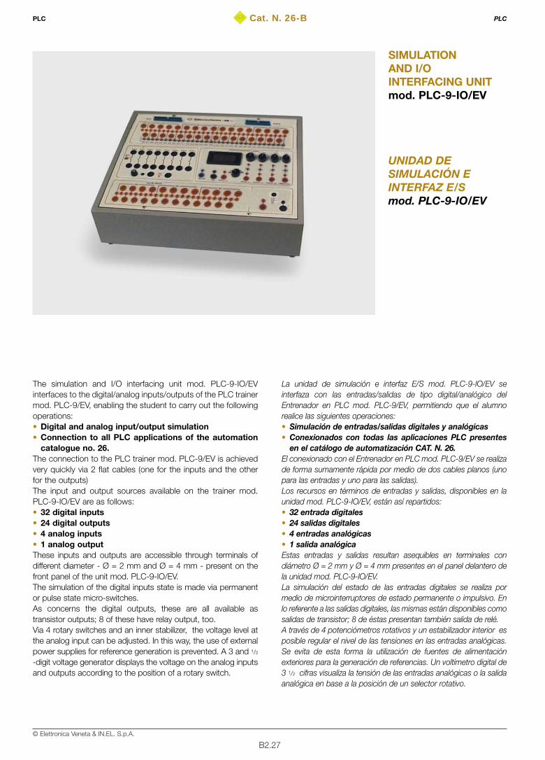
B2.27© Elettronica Veneta & IN.EL. S.p.A.
Cat. N. 26-B
UNIDAD DESIMULACIÓN EINTERFAZ E/Smod. PLC-9-IO/EV
SIMULATIONAND I/OINTERFACING UNITmod. PLC-9-IO/EV
The simulation and I/O interfacing unit mod. PLC-9-IO/EVinterfaces to the digital/analog inputs/outputs of the PLC trainermod. PLC-9/EV, enabling the student to carry out the followingoperations:• Digital and analog input/output simulation • Connection to all PLC applications of the automation
catalogue no. 26.The connection to the PLC trainer mod. PLC-9/EV is achievedvery quickly via 2 flat cables (one for the inputs and the otherfor the outputs) The input and output sources available on the trainer mod.PLC-9-IO/EV are as follows:• 32 digital inputs• 24 digital outputs• 4 analog inputs• 1 analog outputThese inputs and outputs are accessible through terminals ofdifferent diameter - Ø = 2 mm and Ø = 4 mm - present on thefront panel of the unit mod. PLC-9-IO/EV.The simulation of the digital inputs state is made via permanentor pulse state micro-switches. As concerns the digital outputs, these are all available astransistor outputs; 8 of these have relay output, too.Via 4 rotary switches and an inner stabilizer, the voltage level atthe analog input can be adjusted. In this way, the use of externalpower supplies for reference generation is prevented. A 3 and 1/2
-digit voltage generator displays the voltage on the analog inputsand outputs according to the position of a rotary switch.
La unidad de simulación e interfaz E/S mod. PLC-9-IO/EV seinterfaza con las entradas/salidas de tipo digital/analógico delEntrenador en PLC mod. PLC-9/EV, permitiendo que el alumnorealice las siguientes operaciones:• Simulación de entradas/salidas digitales y analógicas• Conexionados con todas las aplicaciones PLC presentes
en el catálogo de automatización CAT. N. 26.El conexionado con el Entrenador en PLC mod. PLC-9/EV se realizade forma sumamente rápida por medio de dos cables planos (unopara las entradas y uno para las salidas).Los recursos en términos de entradas y salidas, disponibles en launidad mod. PLC-9-IO/EV, están así repartidos:• 32 entrada digitales• 24 salidas digitales• 4 entradas analógicas• 1 salida analógicaEstas entradas y salidas resultan asequibles en terminales condiámetro Ø = 2 mm y Ø = 4 mm presentes en el panel delantero dela unidad mod. PLC-9-IO/EV.La simulación del estado de las entradas digitales se realiza pormedio de microinterruptores de estado permanente o impulsivo. Enlo referente a las salidas digitales, las mismas están disponibles comosalidas de transistor; 8 de éstas presentan también salida de relé.A través de 4 potenciómetros rotativos y un estabilizador interior esposible regular el nivel de las tensiones en las entradas analógicas.Se evita de esta forma la utilización de fuentes de alimentaciónexteriores para la generación de referencias. Un voltímetro digital de3 1/2 cifras visualiza la tensión de las entradas analógicas o la salidaanalógica en base a la posición de un selector rotativo.
PLC PLC

B2.28© Elettronica Veneta & IN.EL. S.p.A.
TECHNICAL SPECIFICATIONS• Sheet steel container, chemically treated and painted with
epoxy paint • Side handles to easily move the equipment in the laboratory• Front panel, in insulating material, with silk screen
representation of the diagrams and inner components of theequipment
• 1 3 1/2-digit digital voltmeter for measurement of the voltagepresent across the inputs or the analog output. 0.1Vdc resolution
• 1 rotating switch for voltmeter input selection• 2 analog inputs (voltage): ±10 Vdc• 1 analog output (voltage): ±10 Vdc• 4 rotary switches for setting the analog voltage references in
the 0 to 10 Vdc range • Inner voltage reference obtained via 12-Vdc inner stabilizer• 32 standard digital inputs • Digital input simulator with permanent and pulse state switches• 24 24-Vdc digital outputs • Safety terminals, standard Ø 4 mm and Ø 2 mm for
connection of the inputs and outputs to external devices.• Transistor interfacing of all digital outputs of which 8 (1 byte)
with 10 Aac/2 Adc range relay• 1 flat cable provided with 40-pin connectors for digital/analog
input connection of the PLC trainer mod. PLC-9/EV• 1 flat cable provided with 32-pin connectors for digital/analog
output connections of the PLC trainer mod. PLC-9/EV
DIMENSIONS450x220x110 mm
WEIGHT 8 kg
POWER SUPPLY24 Vdc from PLC trainer mod. PLC-9/EV
CARACTERÍSTICAS TÉCNICAS• Estructura en chapa de acero, tratada químicamente y pintada
con barniz epoxi • Asideros laterales no sobresalientes para un fácil
desplazamiento en el laboratorio• Panel delantero, en material aislante, con representación
sinóptica y serigrafiada de los esquemas y los componentespuestos en el interior del equipo
• 1 voltímetro digital de 3 1/2 dígitos para la medida de la tensiónpresente en las entradas analógicas o en la salida analógica.Resolución 0,1 Vcc
• 1 selector rotativo para la selección de la entrada del voltímetro• 4 entradas analógicas (tensión): ±10 Vcc• 1 salida analógica (tensión): ±10 Vcc• 4 potenciómetros rotativos para la selección de referencias
analógicas de tensión en el margen 0..10 Vcc• Referencia de tensión interior obtenida por medio de
estabilizador interior de 12 Vcc• 32 entradas digitales estándar • Simulador para las entradas digitales con interruptores de
estado permanente e impulsivo• 24 salidas digitales de 24 Vcc • Terminales de seguridad estándar Ø = 4 mm y Ø = 2 mm para
el conexionado de las E/S con los dispositivos externos• Interfaz con el transistor de todas las salidas digitales, de las
cuales 8 (1 byte) también con relé de alcance 10 Aca/2 Acc• 1 cable plano provisto de conectores de 40 pins para el
conexionado de las entradas digitales/analógicas delEntrenador en PLC mod. PLC-9/EV
• 1 cable plano provisto de conectores de 32 pins para elconexionado de las salidas digitales/analógicas del Entrenadoren PLC mod. PLC-9/EV
DIMENSIONES450x220x110 mm
PESO8 Kg
ALIMENTACIÓN24 Vcc desde el Entrenador en PLC mod. PLC-9/EV
PLC PLC
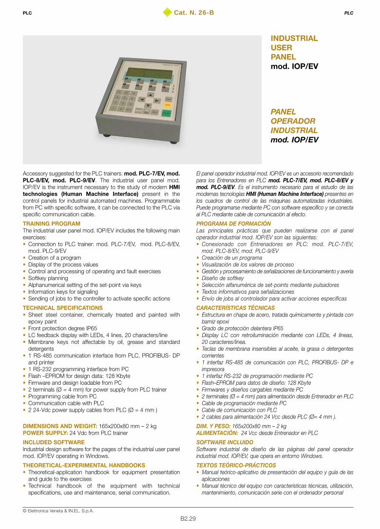
B2.29© Elettronica Veneta & IN.EL. S.p.A.
Cat. N. 26-B
PANELOPERADORINDUSTRIALmod. IOP/EV
INDUSTRIALUSERPANELmod. IOP/EV
Accessory suggested for the PLC trainers: mod. PLC-7/EV, mod.PLC-8/EV, mod. PLC-9/EV. The industrial user panel mod.IOP/EV is the instrument necessary to the study of modern HMItechnologies (Human Machine Interface) present in thecontrol panels for industrial automated machines. Programmablefrom PC with specific software, it can be connected to the PLC viaspecific communication cable.
TRAINING PROGRAMThe industrial user panel mod. IOP/EV includes the following mainexercises: • Connection to PLC trainer: mod. PLC-7/EV, mod. PLC-8/EV,
mod. PLC-9/EV• Creation of a program• Display of the process values • Control and processing of operating and fault exercises • Softkey planning• Alphanumerical setting of the set-point via keys• Information keys for signaling • Sending of jobs to the controller to activate specific actions
TECHNICAL SPECIFICATIONS• Sheet steel container, chemically treated and painted with
epoxy paint• Front protection degree IP65• LC feedback display with LEDs, 4 lines, 20 characters/line• Membrane keys not affectable by oil, grease and standard
detergents • 1 RS-485 communication interface from PLC, PROFIBUS- DP
and printer • 1 RS-232 programming interface from PC• Flash –EPROM for design data: 128 Kbyte• Firmware and design loadable from PC• 2 terminals (Ø = 4 mm) for power supply from PLC trainer• Programming cable from PC• Communication cable with PLC• 2 24-Vdc power supply cables from PLC (Ø = 4 mm )
DIMENSIONS AND WEIGHT: 165x200x80 mm – 2 kgPOWER SUPPLY: 24 Vdc from PLC trainer
INCLUDED SOFTWAREIndustrial design software for the pages of the industrial user panelmod. IOP/EV operating in Windows.
THEORETICAL-EXPERIMENTAL HANDBOOKS • Theoretical-application handbook for equipment presentation
and guide to the exercises• Technical handbook of the equipment with technical
specifications, use and maintenance, serial communication.
El panel operador industrial mod. IOP/EV es un accesorio recomendadopara los Entrenadores en PLC mod. PLC-7/EV, mod. PLC-8/EV ymod. PLC-9/EV. Es el instrumento necesario para el estudio de lasmodernas tecnologías HMI (Human Machine Interface) presentes enlos cuadros de control de las máquinas automatizadas industriales.Puede programarse mediante PC con software específico y se conectaal PLC mediante cable de comunicación al efecto.
PROGRAMA DE FORMACIÓNLas principales prácticas que pueden realizarse con el paneloperador industrial mod. IOP/EV son las siguientes:• Conexionado con Entrenadores en PLC: mod. PLC-7/EV,
mod. PLC-8/EV, mod. PLC-9/EV• Creación de un programa• Visualización de los valores de proceso• Gestión y procesamiento de señalizaciones de funcionamiento y avería• Diseño de softkey• Selección alfanumérica de set-points mediante pulsadores• Textos informativos para señalizaciones• Envío de jobs al controlador para activar acciones específicas
CARACTERÍSTICAS TÉCNICAS• Estructura en chapa de acero, tratada químicamente y pintada con
barniz epoxi• Grado de protección delantera IP65• Display LC con retroiluminación mediante con LEDs, 4 líneas,
20 caracteres/línea.• Teclas de membrana insensibles al aceite, la grasa o detergentes
corrientes• 1 interfaz RS-485 de comunicación con PLC, PROFIBUS- DP e
impresora • 1 interfaz RS-232 de programación mediante PC• Flash–EPROM para datos de diseño: 128 Kbyte• Firmwares y diseños cargables mediante PC• 2 terminales (Ø = 4 mm) para alimentación desde Entrenador en PLC• Cable de programación mediante PC• Cable de comunicación con PLC• 2 cables para alimentación 24 Vcc desde PLC (Ø= 4 mm ).
DIM. Y PESO: 165x200x80 mm – 2 kgALIMENTACIÓN: 24 Vcc desde Entrenador en PLC
SOFTWARE INCLUIDOSoftware industrial de diseño de las páginas del panel operadorindustrial mod. IOP/EV, que opera en entorno Windows.
TEXTOS TEÓRICO-PRÁCTICOS• Manual teórico-aplicativo de presentación del equipo y guía de las
aplicaciones• Manual técnico del equipo con características técnicas, utilización,
mantenimiento, comunicación serie con el ordenador personal
PLC PLC
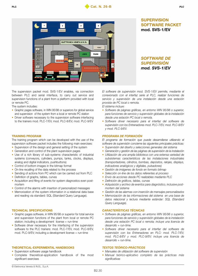
B2.30© Elettronica Veneta & IN.EL. S.p.A.
Cat. N. 26-B
SOFTWARE DESUPERVISIÓNmod. SVS-1/EV
SUPERVISIONSOFTWARE PACKETmod. SVS-1/EV
The supervision packet mod. SVS-1/EV enables, via connectionbetween PLC and serial interface, to carry out service andsupervision functions of a plant from a platform provided with localor remote PC.The system includes:• Graphic pages software, in WIN 95/98 or superiors for global service
and supervision of the system from a local or remote PC station • Driver software necessary to the supervision software interfacing
to the trainers mod. PLC-7/EV, mod. PLC-8/EV, mod. PLC-9/EV
TRAINING PROGRAMThe training program which can be developed with the use of thesupervision software packet includes the following main exercises:• Supervision of the design and general setting of the system • Generation and control of the plant supervision pages• Use of a rich library of sub-systems characteristic of industrial
systems (conveyors, cylinders, pumps, tanks, clocks, displays,analog and digital indicators, pushbuttons)
• Control of bottom images in the bitmap format• On-line recalling of the data related to the process• Sending of actions from PC which can be carried out from PLC• Definition of graphs, tables, curves• Acquisition and filing of events for system diagnostics even post-
mortem • Control of the alarms with insertion of personalized messages• Memorization of the system information in a relational data base
and reading via standard: SQL (Standard Query Language).
TECHNICAL SPECIFICATIONS• Graphic pages software, in WIN 95/98 or superior for total service
and supervision functions of the plant from local or remote PCstation; including a development license + run-time
• Software driver necessary for the interfacing of the supervisionsoftware to the PLC trainers: mod. PLC-7/EV, mod. PLC-8/EV,mod. PLC-9/EV; including a development license + run-time
THEORETICAL-EXPERIMENTAL HANDBOOKS • Supervision software usage handbook • Complete theoretical-application handbook of the most
significant exercises
El software de supervisión mod. SVS-1/EV permite, mediante elconexionado con el interfaz serie al PLC, realizar funciones deservicio y supervisión de una instalación desde una estaciónprovista de PC local o remota.El sistema incluye:• Software de páginas gráficas, en entorno WIN 95/98 o superior,
para funciones de servicio y supervisión globales de la instalacióndesde una estación PC local o remota.
• Software driver necesario para el interfaz del software desupervisión con los Entrenadores mod. PLC-7/EV, mod. PLC-8/EVy mod. PLC-9/EV.
PROGRAMA DE FORMACIÓNEl programa de formación que puede desarrollarse utilizando elsoftware de supervisión concierne las siguientes principales prácticas:• Supervisión del diseño y selecciones generales del sistema• Generación y gestión de las páginas de supervisión de la instalación• Utilización de una amplia biblioteca con una extensa variedad de
subsistemas característicos de las instalaciones industriales(transportadores, cilindros, bombas, depósitos, relojes, displays,indicadores analógicos y digitales, pulsadores)
• Gestión de imágenes de fondo en formato bitmap• Selección on-line de los datos referentes al proceso• Envío de acciones desde PC realizables mediante PLC• Definición de gráficos, tablas, curvas• Adquisición y archivo de eventos para diagnóstico, inclusive post-
mortem del sistema • Gestión de las alarmas con inserción de mensajes personalizados• Memorización de las informaciones del sistema en una base de
datos relacional y lectura mediante estándar: SQL (StandardQuery Language).
CARACTERÍSTICAS TÉCNICAS• Software de páginas gráficas, en entorno WIN 95/98 o superior,
para funciones de servicio y supervisión globales de la instalacióndesde una estación PC local o remota; incluye una licencia dedesarrollo + run-time.
• Software driver necesario para el interfaz del software desupervisión con los Entrenadores en PLC: mod. PLC-7/EV,mod. PLC-8/EV y mod. PLC-9/EV; incluye una licencia dedesarrollo + run-time.
TEXTOS TEÓRICO-PRÁCTICOS• Manuales de utilización del software de supervisión• Manual teórico-aplicativo completo de las prácticas más
significativas
PLC PLC
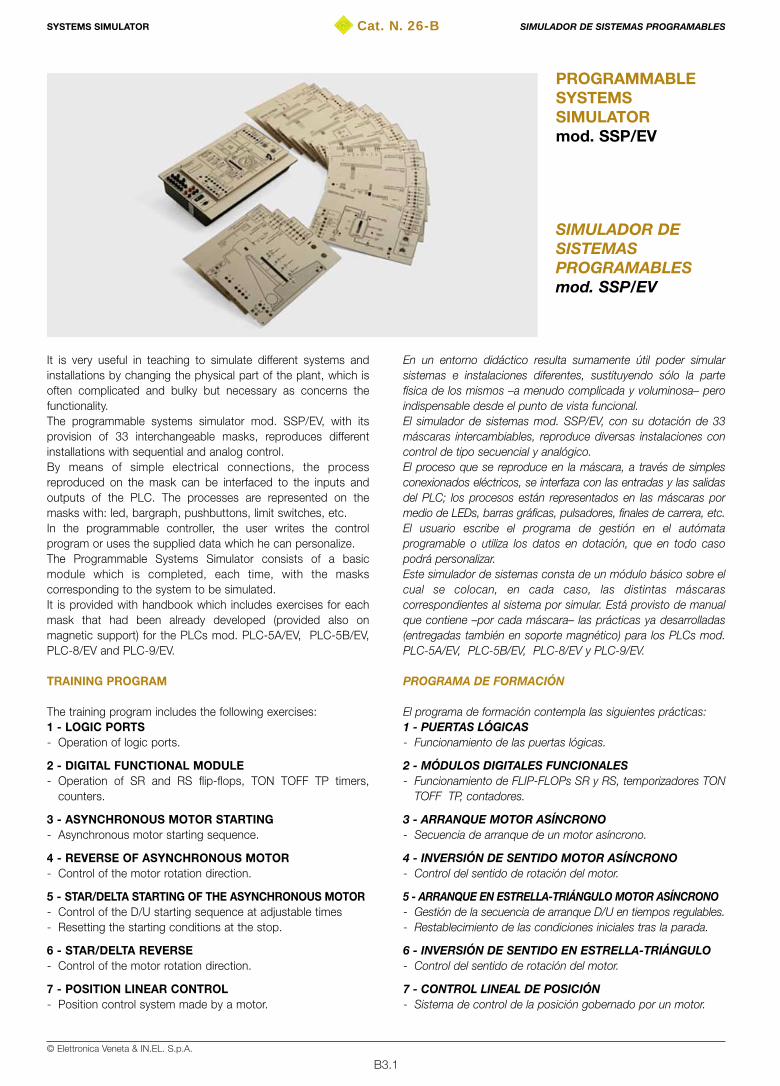
B3.1© Elettronica Veneta & IN.EL. S.p.A.
Cat. N. 26-B
SIMULADOR DESISTEMASPROGRAMABLESmod. SSP/EV
PROGRAMMABLESYSTEMSSIMULATORmod. SSP/EV
It is very useful in teaching to simulate different systems andinstallations by changing the physical part of the plant, which isoften complicated and bulky but necessary as concerns thefunctionality.The programmable systems simulator mod. SSP/EV, with itsprovision of 33 interchangeable masks, reproduces differentinstallations with sequential and analog control.By means of simple electrical connections, the processreproduced on the mask can be interfaced to the inputs andoutputs of the PLC. The processes are represented on themasks with: led, bargraph, pushbuttons, limit switches, etc. In the programmable controller, the user writes the controlprogram or uses the supplied data which he can personalize.The Programmable Systems Simulator consists of a basicmodule which is completed, each time, with the maskscorresponding to the system to be simulated.It is provided with handbook which includes exercises for eachmask that had been already developed (provided also onmagnetic support) for the PLCs mod. PLC-5A/EV, PLC-5B/EV,PLC-8/EV and PLC-9/EV.
TRAINING PROGRAM
The training program includes the following exercises:1 - LOGIC PORTS- Operation of logic ports.
2 - DIGITAL FUNCTIONAL MODULE- Operation of SR and RS flip-flops, TON TOFF TP timers,
counters.
3 - ASYNCHRONOUS MOTOR STARTING - Asynchronous motor starting sequence.
4 - REVERSE OF ASYNCHRONOUS MOTOR- Control of the motor rotation direction.
5 - STAR/DELTA STARTING OF THE ASYNCHRONOUS MOTOR- Control of the D/U starting sequence at adjustable times- Resetting the starting conditions at the stop.
6 - STAR/DELTA REVERSE - Control of the motor rotation direction.
7 - POSITION LINEAR CONTROL- Position control system made by a motor.
En un entorno didáctico resulta sumamente útil poder simularsistemas e instalaciones diferentes, sustituyendo sólo la partefísica de los mismos –a menudo complicada y voluminosa– peroindispensable desde el punto de vista funcional.El simulador de sistemas mod. SSP/EV, con su dotación de 33máscaras intercambiables, reproduce diversas instalaciones concontrol de tipo secuencial y analógico.El proceso que se reproduce en la máscara, a través de simplesconexionados eléctricos, se interfaza con las entradas y las salidasdel PLC; los procesos están representados en las máscaras pormedio de LEDs, barras gráficas, pulsadores, finales de carrera, etc.El usuario escribe el programa de gestión en el autómataprogramable o utiliza los datos en dotación, que en todo casopodrá personalizar.Este simulador de sistemas consta de un módulo básico sobre elcual se colocan, en cada caso, las distintas máscarascorrespondientes al sistema por simular. Está provisto de manualque contiene –por cada máscara– las prácticas ya desarrolladas(entregadas también en soporte magnético) para los PLCs mod.PLC-5A/EV, PLC-5B/EV, PLC-8/EV y PLC-9/EV.
PROGRAMA DE FORMACIÓN
El programa de formación contempla las siguientes prácticas:1 - PUERTAS LÓGICAS - Funcionamiento de las puertas lógicas.
2 - MÓDULOS DIGITALES FUNCIONALES- Funcionamiento de FLIP-FLOPs SR y RS, temporizadores TON
TOFF TP, contadores.
3 - ARRANQUE MOTOR ASÍNCRONO- Secuencia de arranque de un motor asíncrono.
4 - INVERSIÓN DE SENTIDO MOTOR ASÍNCRONO- Control del sentido de rotación del motor.
5 - ARRANQUE EN ESTRELLA-TRIÁNGULO MOTOR ASÍNCRONO- Gestión de la secuencia de arranque D/U en tiempos regulables.- Restablecimiento de las condiciones iniciales tras la parada.
6 - INVERSIÓN DE SENTIDO EN ESTRELLA-TRIÁNGULO- Control del sentido de rotación del motor.
7 - CONTROL LINEAL DE POSICIÓN - Sistema de control de la posición gobernado por un motor.
SYSTEMS SIMULATOR SIMULADOR DE SISTEMAS PROGRAMABLES
B3.2© Elettronica Veneta & IN.EL. S.p.A.
8 - DAHLANDER MOTOR STARTING- Control of the motor HIGH / LOW speeds.
9 - MOTOR WITH TWO SEPARATED COILS - Control of a motor with two separated coils.
10 - ASYNCHRONOUS MOTOR STARTING WITHWOUNDED ROTOR
- Control of the start sequence with 1, 2 or 3 steps(selectable).
- Resetting the starting conditions at the stop.
11 - CONVEYOR BELTS 1- Sandy material conveying process controlled with three
conveyor belts.
12 - REACTIVE POWER COMPENSATION- Circuit for reactive compensation.
13 - RADIATORS- Control of a heating system.
14 - SEQUENTIAL LIGHT INSTALLATION - Control of different sequential starting programs made by 1 to
8 lamps, with single variation of the start up times.- Operation: AUTO/MAN and UP/DOWN.
15 - FILLING SYSTEM 1- Automatic filling process of test tubes.
16 - FILLING SYSTEM 2- Filling process of three tanks in line.
17 - CARBON TREATMENT- Carbon working process.
18 - EMBOSSING PROCESS- Embossing process of metal disks controlled with an
electropneumatic system.
19 - VENTILATION SYSTEM- Control of a ventilation system in an underground parking.
20 - TRAFFIC LIGHT- Control of a traffic light to enable road works.
21 - TRAFFIC LIGHT FOR PEDESTRIAN CROSSING- Control of a traffic light on main road with pedestrian crossing.
22 - CONVEYOR BELTS 2- Serial control of five conveyor belts to convey 4 different
products.
23 - CANALIZATION SYSTEM- Canalization process of two different products.
24 - CONTROL OF THE LEVEL IN A TANKControl of the tank level in these modes:- ON/OFF- Analogic
25 - REACTOR- Reaction control through the 3 inputs (substance, inert gas,
catalyst), the refrigerant, the product and the mixer exhaustion.
8 - ARRANQUE MOTOR DAHLANDER- Gestión de la velocidad ALTA/BAJA del motor.
9 - MOTOR CON DOS BOBINAS SEPARADAS- Control de un motor con dos bobinas separadas.
10 - ARRANQUE MOTOR ASÍNCRONO CON ROTORDEVANADO
- Control de la secuencia de START con 1, 2 ó 3 escalones(seleccionables).
- Restablecimiento de las condiciones iniciales tras la parada.
11 - CINTAS TRANSPORTADORAS 1- Proceso de transporte de material arenisco, controlado por tres
cintas transportadoras.
12 - COMPENSACIÓN POTENCIA REACTIVA- Circuito para la compensación de la potencia reactiva.
13 - RADIADORES- Control de una instalación de calefacción.
14 - LETRERO LUMINOSO SECUENCIAL- Control de varios programas con encendido secuencial de 1 a 8
lámparas y variación de los tiempos de encendido de cada uno.- Operación: AUTO/MAN y UP/DOWN.
15 - SISTEMA DE LLENADO 1- Proceso automático de llenado de probetas.
16 - SISTEMA DE LLENADO 2- Proceso de llenado de tres tanques en línea.
17 - TRATAMIENTO DEL CARBÓN- Proceso para el tratamiento del carbón.
18 - PROCESO DE GOFRADO- Proceso para el estampado en relieve de discos metálicos
gobernado a través del control de un sistema electroneumático.
19 - SISTEMA DE VENTILACIÓN- Control de un sistema de ventilación en un aparcamiento
subterráneo.
20 - SEMÁFORO- Control de un semáforo para permitir la realización de los
trabajos de carretera.
21 - SEMÁFORO PEATONAL- Control de un semáforo en una carretera principal con cruce de
peatones.
22 - CINTAS TRANSPORTADORAS 2- Control en serie de cinco cintas transportadoras para el
transporte de cuatro productos diferentes.
23 - SISTEMA DE CANALIZACIÓN- Proceso de canalización de dos productos diferentes.
24 - CONTROL DEL NIVEL DE UN TANQUE- Gestión del nivel del tanque en modo:- ON/OFF- Analógico
25 - REACTOR - Gestión de la reacción con control de tres entradas (sustancia,
gas inerte, catalizador), del refrigerante, de la descarga delproducto y del mezclador.
SYSTEMS SIMULATOR SIMULADOR DE SISTEMAS PROGRAMABLES
B3.3© Elettronica Veneta & IN.EL. S.p.A.
26 - CONTROL of a HOIST- Control of the motion of a hoist at the 4 floors.
27 - FILLING A STORAGE BIN- Filling process control of a storage bin via 4 pumps.
28 - PUMPING SYSTEM FOR BLACK LIQUORS- Control of a tank evacuation process from black liquors.
29 - OPERATION MONITORING OF THREE PUMPS- Checking the proper operation of three pumps for the level
control inside a tank.
30 - LEVEL CONTROL OF A TANK VIA PRESSURESENSORS
- Control of the level inside a tank using pressure sensors to fixthe height of the water column.
31 - BEVERAGE DISPENSER- Simulation of the different sequences of a beverage dispenser.
32 - MECHANICAL MACHINING LINE- Control of all phases.- Implementation of different sequences with use of some/all
phases.
33 - MIXER- Mixing process control of different substances.
TECHNICAL SPECIFICATIONSThe Programmable System Simulator consists of a panel whichcan be used as work unit mounted on a vertical support.All I/O lines can be connected via safety cables with pinØ = 4 mm or via Centronix parallel port. Two potentiometersenable the selection of the value of the system’s analogvariables, e.g. the filling speed of a storage bin, theupward/downward speed of a hoist.
PROVIDED MASKS
1 - LOGIC PORTS
2 - DIGITAL FUNCTIONAL MODULE
3 - ASYNCHRONOUS MOTOR STARTING
4 - REVERSE OF ASYNCHRONOUS MOTOR
7 - STAR/DELTA STARTING OF THE ASYNCHRONOUSMOTOR
6 - STAR/DELTA REVERSE
7 - POSITION LINEAR CONTROL
8 - DAHLANDER MOTOR STARTING
9 - MOTOR WITH TWO SEPARATED COILS
10 - ASYNCHRONOUS MOTOR STARTING WITHWOUNDED ROTOR
11 - CONVEYOR BELTS 1
12 - REACTIVE POWER COMPENSATION
13 - RADIATORS
26 - MONTACARGAS- Gestión de un montacargas que funciona en 4 pisos.
27 - LLENADO DE UN SILO- Gestión del proceso de llenado de un silo a través del control de
cuatro bombas.
28 - SISTEMA DE BOMBEO DE AGUAS NEGRAS- Gestión del proceso de vaciado de un tanque con aguas negras.
29 - MONITORIZACIÓN DEL FUNCIONAMIENTO DE TRESBOMBAS
- Gestión del correcto funcionamiento de tres bombas para elcontrol del nivel en el interior de un tanque.
30 - CONTROL DE NIVEL DE TANQUE A TRAVÉS DESENSORES DE PRESIÓN
- Gestión del nivel en el interior de un tanque, utilizando sensoresde presión para establecer la altura de la columna de agua.
31 - DISTRIBUIDOR DE BEBIDAS- Simulación de las diferentes secuencias de un distribuidor de
bebidas.
32 - LÍNEA DE MECANIZADO- Gestión de todas las fases.- Implementación de secuencias diferentes con utilización de
algunas/todas las fases.
33 - MEZCLADOR- Gestión del proceso de mezcla de sustancias diferentes.
CARACTERÍSTICAS TÉCNICASEste simulador consta de un panel que puede utilizarse comounidad de sobremesa o montado sobre un soporte vertical.Todas las líneas de E/S pueden conectarse a través de cables deseguridad con terminal Ø = 4 mm o puerto Centronix paralelo.Dos potenciómetros permiten seleccionar el valor de las variablesanalógicas del sistema; por ejemplo, la velocidad de llenado de unsilo, la velocidad de ascenso/descenso de un montacargas.
MÁSCARAS EN DOTACIÓN
1 - PUERTAS LÓGICAS
2 - MÓDULOS DIGITALES FUNCIONALES
3 - ARRANQUE MOTOR ASÍNCRONO
4 - INVERSIÓN DE SENTIDO MOTOR ASÍNCRONO
5 - ARRANQUE EN ESTRELLA-TRIÁNGULO MOTORASÍNCRONO
6 - INVERSIÓN DE SENTIDO EN ESTRELLA-TRIÁNGULO
7 - CONTROL LINEAL DE POSICIÓN
8 - ARRANQUE MOTOR DAHLANDER
9 - MOTOR CON DOS BOBINAS SEPARADAS
10 - ARRANQUE MOTOR ASÍNCRONO CON ROTORBOBINADO
11 - CINTAS TRANSPORTADORAS 1
12 - COMPENSACIÓN POTENCIA REACTIVA
13 - RADIADORES
SYSTEMS SIMULATOR SIMULADOR DE SISTEMAS PROGRAMABLES
B3.4© Elettronica Veneta & IN.EL. S.p.A.
14 - SEQUENTIAL LIGHT INSTALLATION
15 - FILLING SYSTEM 1
16 - FILLING SYSTEM 2
17 - CARBON TREATMENT
18 - EMBOSSING PROCESS
19 - VENTILATION SYSTEM
20 - TRAFFIC LIGHT
21 - TRAFFIC LIGHT FOR PEDESTRIAN CROSSING
22 - CONVEYOR BELTS 2
23 - CANALIZATION SYSTEM
24 - CONTROL OF THE LEVEL IN A TANK
25 - REACTOR
26 - CONTROL of a HOIST
27 - FILLING A STORAGE BIN
28 - PUMPING SYSTEM FOR BLACK LIQUORS
29 - OPERATION MONITORING OF THREE PUMPS
30 - LEVEL CONTROL OF A TANK VIA PRESSURESENSORS
31 - BEVERAGE DISPENSER
32 - MECHANICAL MACHINING LINE
33 - MIXER
DIMENSIONS and WEIGHT440x297x110 mm – 4.3 kg
PROVIDED ACCESSORIES• Set of 24 cables with Ø 4-mm pins
POWER SUPPLY230V – 50-60 Hz
THEORETICAL-EXPERIMENTAL HANDBOOKS • Handbook for installation, theoretical-experimental use with
exercises. It includes the application software for the PLCswith magnetic support.
MINIMUM PLC REQUIREMENTSPLC provided with:- 14 positive logic digital inputs- 8 24-Vdc digital outputs- 2 0-10-Vdc analog outputs - 1 0-10-Vdc analog output
SUGGESTED PLCThe systems simulator mod. SSP/EV can be used together with astandard PLC: mod. PLC-5A/EV, mod. PLC-5B/EV, mod. PLC-8/EV,PLC-9/EV.The PLC mod. PLC-9/EV is provided also with the flat cable fordirect PLC – SSP connection.
14 - LETRERO LUMINOSO SECUENCIAL
15 - SISTEMA DE LLENADO 1
16 - SISTEMA DE LLENADO 2
17 - TRATAMIENTO DEL CARBÓN
18 - PROCESO DE GOFRADO
19 - SISTEMA DE VENTILACIÓN
20 - SEMÁFORO
21 - SEMÁFORO PEATONAL
22 - CINTAS TRANSPORTADORAS 2
23 - SISTEMA DE CANALIZACIÓN
24 - CONTROL DEL NIVEL DE UN TANQUE
25 - REACTOR
26 - MONTACARGAS
27 - LLENADO DE UN SILO
28 - SISTEMA DE BOMBEO DE AGUAS NEGRAS
29 - MONITORIZACIÓN FUNCIONAMIENTO DE TRESBOMBAS
30 - CONTROL DE NIVEL DE TANQUE A TRAVÉS DESENSORES DE PRESIÓN
31 - DISTRIBUIDOR DE BEBIDAS
32 - LÍNEA DE MECANIZADO
33 - MEZCLADOR
DIMENSIONES y PESO440x297x110 mm – 4,3 kg
ACCESORIOS EN DOTACIÓN• Juego de 24 cables con terminales Ø 4 mm
ALIMENTACIÓN230 V – 50-60 Hz
TEXTOS TEÓRICO-PRÁCTICOSManual de instalación, uso teórico-práctico con prácticas. Incluyeel software aplicativo para PLCs en soporte magnético.
REQUISITOS MÍNIMOS DEL PLCPLC provisto de:- 14 entradas digitales lógica positiva- 8 salidas digitales de 24 Vcc- 2 entradas analógicas 0-10 Vcc- 1 salida analógica 0-10 Vcc
PLC RECOMENDADOEl simulador mod. SSP/EV puede conectarse con un autómatamodelo comercial PLC-5A/EV, PLC-5B/EV, PLC-8/EV o PLC-9/EV.Con el PLC mod. PLC-9/EV se suministra un cable plano para elconexionado directo PLC–SSP.
SYSTEMS SIMULATOR SIMULADOR DE SISTEMAS PROGRAMABLES
B4.1© Elettronica Veneta & IN.EL. S.p.A.
PAG.
APPLICATIONS B4.1
Industrial installationmod. C/EV B4.3
Automation of sliding gatesmod. MR/EV B4.5
Electropneumatic installationmod. D/EV B4.7
Trainer for electropneumatic actuatorsmod. EAT/EV B4.11
Robomatic Trainermod. RMT/EV B4.13
3-floor lift mod. HM400/EV B4.15
Automation process with conveyormod. TSM-700/EV B4.17
PAGE
APLICACIONES B4.1
Instalaciones eléctricas industrialesmod. C/EV B4.3
Automatización de verjas corredizasmod. MR/EV B4.5
Instalaciones electroneumáticasmod. D/EV B4.7
Entrenador en actuadores electroneumáticosmod. EAT/EV B4.11
Brazo manipulador neumáticomod. RMT/EV B4.13
Ascensor de 3 pisosmod. HM400/EV B4.15
Proceso de automatización con transportadormod. TSM-700/EV B4.17
Cat. N. 26-BAPPLICATIONS APLICACIONES

B4.2© Elettronica Veneta & IN.EL. S.p.A.
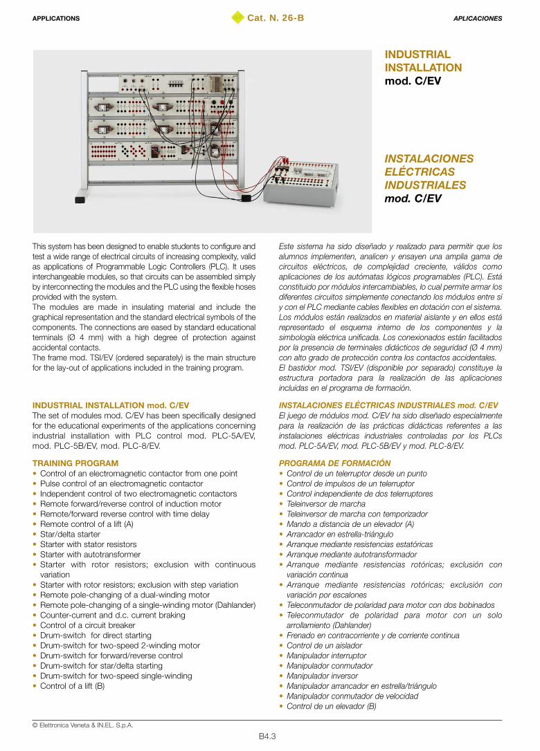
B4.3© Elettronica Veneta & IN.EL. S.p.A.
Cat. N. 26-B
INSTALACIONESELÉCTRICASINDUSTRIALESmod. C/EV
INDUSTRIALINSTALLATIONmod. C/EV
This system has been designed to enable students to configure andtest a wide range of electrical circuits of increasing complexity, validas applications of Programmable Logic Controllers (PLC). It usesinterchangeable modules, so that circuits can be assembled simplyby interconnecting the modules and the PLC using the flexible hosesprovided with the system.The modules are made in insulating material and include thegraphical representation and the standard electrical symbols of thecomponents. The connections are eased by standard educationalterminals (Ø 4 mm) with a high degree of protection againstaccidental contacts.The frame mod. TSI/EV (ordered separately) is the main structurefor the lay-out of applications included in the training program.
INDUSTRIAL INSTALLATION mod. C/EVThe set of modules mod. C/EV has been specifically designedfor the educational experiments of the applications concerningindustrial installation with PLC control mod. PLC-5A/EV,mod. PLC-5B/EV, mod. PLC-8/EV.
TRAINING PROGRAM• Control of an electromagnetic contactor from one point • Pulse control of an electromagnetic contactor• Independent control of two electromagnetic contactors • Remote forward/reverse control of induction motor • Remote/forward reverse control with time delay• Remote control of a lift (A)• Star/delta starter• Starter with stator resistors • Starter with autotransformer• Starter with rotor resistors; exclusion with continuous
variation• Starter with rotor resistors; exclusion with step variation• Remote pole-changing of a dual-winding motor• Remote pole-changing of a single-winding motor (Dahlander)• Counter-current and d.c. current braking • Control of a circuit breaker • Drum-switch for direct starting• Drum-switch for two-speed 2-winding motor • Drum-switch for forward/reverse control • Drum-switch for star/delta starting• Drum-switch for two-speed single-winding • Control of a lift (B)
Este sistema ha sido diseñado y realizado para permitir que losalumnos implementen, analicen y ensayen una amplia gama decircuitos eléctricos, de complejidad creciente, válidos comoaplicaciones de los autómatas lógicos programables (PLC). Estáconstituido por módulos intercambiables, lo cual permite armar losdiferentes circuitos simplemente conectando los módulos entre síy con el PLC mediante cables flexibles en dotación con el sistema.Los módulos están realizados en material aislante y en ellos estárepresentado el esquema interno de los componentes y lasimbología eléctrica unificada. Los conexionados están facilitadospor la presencia de terminales didácticos de seguridad (Ø 4 mm)con alto grado de protección contra los contactos accidentales.El bastidor mod. TSI/EV (disponible por separado) constituye laestructura portadora para la realización de las aplicacionesincluidas en el programa de formación.
INSTALACIONES ELÉCTRICAS INDUSTRIALES mod. C/EV El juego de módulos mod. C/EV ha sido diseñado especialmentepara la realización de las prácticas didácticas referentes a lasinstalaciones eléctricas industriales controladas por los PLCsmod. PLC-5A/EV, mod. PLC-5B/EV y mod. PLC-8/EV.
PROGRAMA DE FORMACIÓN• Control de un telerruptor desde un punto• Control de impulsos de un telerruptor • Control independiente de dos telerruptores • Teleinversor de marcha• Teleinversor de marcha con temporizador• Mando a distancia de un elevador (A)• Arrancador en estrella-triángulo• Arranque mediante resistencias estatóricas• Arranque mediante autotransformador • Arranque mediante resistencias rotóricas; exclusión con
variación continua• Arranque mediante resistencias rotóricas; exclusión con
variación por escalones• Teleconmutador de polaridad para motor con dos bobinados• Teleconmutador de polaridad para motor con un solo
arrollamiento (Dahlander)• Frenado en contracorriente y de corriente continua • Control de un aislador• Manipulador interruptor• Manipulador conmutador• Manipulador inversor• Manipulador arrancador en estrella/triángulo• Manipulador conmutador de velocidad• Control de un elevador (B)
APPLICATIONS APLICACIONES
B4.4© Elettronica Veneta & IN.EL. S.p.A.
• Switching-on of a sequential advertising sign • Remote star/delta starter + forward/reverse control • Emergency/reserve power supply • Traffic light installation• Basic control of a crane
TECHNICAL SPECIFICATIONSThe set of modules for industrial installation mod. C/EV consists of:• 1 Module type AZ-10
5 fuse-holders with 4/6-A sectionable fuses• 1 Module type AZ-15
1 transformer 115-230 / 12-24 V 50-60 Hz 72 VA• 4 Modules type AZ-41
1 electromagnetic contactors for industrial uses, 24-Vac coil• 6 Modules type AZ-42
1 time-delay relay 1.5 - 30 s, 24-Vac coil • 3 Modules type AZ-43
1 auxiliary relay for industrial uses– 24-Vac coil• 2 Modules type AZ-44
3 push-buttons for industrial uses• 2 Modules type AZ-46
3 lamp-holders for industrial uses with 24-V lamps• 1 Module type AZ-47
1 three-phase Graetz-bridge 600 V 25 A max.• 2 Modules type AZ-48
1 thermal relay for industrial uses with NO-NC contacts• 2 Modules type AZ-49a
1 microswitch for industrial uses• 2 Modules type AZ-49b
1 microswitch for industrial uses (type MBB)• 2 Modules type AZ-49c
1 microswitch for industrial uses (type BBM)• 1 Module type AZ-50
1 3-pole drum-switch, 16 A 400 V• 1 Module type AZ-51
1 3-pole drum-switch (commutator), 16 A 400 V• 1 Module type AZ-52
1 3-pole drum switch (reverser) 16 A 400 V• 1 Module type AZ-53
1 star-delta starter switch 16 A 400 V• 1 Module type AZ-54
1 3-pole drum-switch (pole-changing for Dahlander motors)16 A 400 V
• 1 Module type AZ-553 three-phase terminal boards for power circuits
• 1 Module type AZ-569 terminal boards for switching/connection of control circuits
• 1 Traffic light unit mod. TL-11 miniature traffic light with 12 24-V lamps
ACCESSORIESFrame TSI/EV. It is carried out with aluminum and sheet steelsections, chemically treated and painted with epoxy paint. The framebase is provided with feet needing no fixing element to the table.
Dimensions: 1000x500x800 mmWeight: 10 kg
Set of 60 cables with Ø 4-mm safety pins
POWER SUPPLY: 3x400 (3x230 V)/PE – 50-60 Hz
THEORETICAL-EXPERIMENTAL HANDBOOKS• Theoretical-application handbook for equipment presentation• Handbook for the applications with PLC-5A/EV, PLC-5B/EV, PLC-8/EV
• Encendido secuencial de letreros luminosos• Teleinversor, arrancador en estrella/triángulo• Línea eléctrica de alimentación de reserva/emergencia• Instalación de semáforo• Control de una grúa
CARACTERÍSTICAS TÉCNICASEl juego de módulos para realizar las instalaciones eléctricasindustriales mod. C/EV está constituido por:• 1 Módulo tipo AZ-10
5 portafusibles de panel con fusibles aislables 4/6 A• 1 Módulo tipo AZ-15
1 transformador 115-230/12-24 V 50-60 Hz 72 VA• 4 Módulos tipo AZ-41
1 contactor electromagnético para usos industriales, bobina 24 Vca• 6 Módulos tipo AZ-42
1 temporizador 1,5 - 30 s, bobina 24 Vca• 3 Módulos tipo AZ-43
1 relé auxiliar para usos industriales – bobina 24 Vca• 2 Módulos tipo AZ-44
3 pulsadores para usos industriales• 2 Módulos tipo AZ-46
3 portalámparas para usos industriales con lámparas 24 V• 1 Módulo tipo AZ-47
1 puente de Graetz trifásico 600 V 25 A máx.• 2 Módulos tipo AZ-48
1 relé térmico para usos industriales con contactos NA-NC• 2 Módulos tipo AZ-49a
1 microinterruptor para usos industriales• 2 Módulos tipo AZ-49b
1 microinterruptor para usos industriales (tipo MBB)• 2 Módulos tipo AZ-49c
1 microinterruptor para usos industriales (tipo BBM)• 1 Módulo tipo AZ-50
1 interruptor manipulador tripolar 16 A-400 V• 1 Módulo tipo AZ-51
1 manipulador conmutador tripolar 16 A-400 V• 1 Módulo tipo AZ-52
1 manipulador inversor tripolar 16 A-400 V• 1 Módulo tipo AZ-53
1 manipulador arrancador en estrella/triángulo 16 A-400 V• 1 Módulo tipo AZ-54
1 manipulador tripolar (conmutador de polaridad para motoresDahlander) 16 A-400 V
• 1 Módulo tipo AZ-553 cajas de bornes trifásicos para circuitos de potencia
• 1 Módulo tipo AZ-569 cajas de bornes para conmutación/conexión circuitos de control
• 1 Unidad semáforo mod. TL-11 semáforo en miniatura con 12 lámparas de 24 V
ACCESORIOSBastidor mod. TSI/EV. Está realizado en aluminio perfilado y chapa deacero tratados químicamente y pintados con varias manos de barnizepoxi. La base del bastidor está provista de patas transversales y norequiere dispositivos de sujeción a la mesa de soporte.
Dimensiones: 1100x500x800 mmPeso: 10 kg
Juego de 60 cables con terminales de seguridad Ø 4 mm
ALIMENTACIÓN ELÉCTRICA: 3x400 (3x230 V)/PE 50-60 Hz
TEXTOS TEÓRICO-PRÁCTICOS• Manual teórico-aplicativo de presentación del equipo • Manual de las aplicaciones con PLC-5A/EV, PLC-5B/EV, PLC-8/EV
APPLICATIONS APLICACIONES
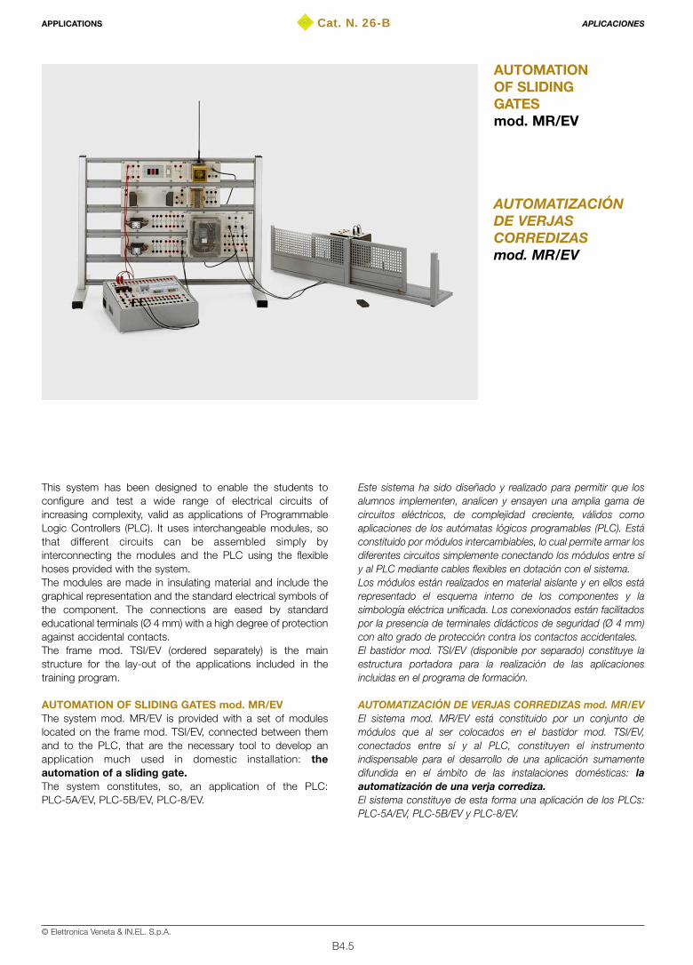
B4.5© Elettronica Veneta & IN.EL. S.p.A.
Cat. N. 26-B
AUTOMATIZACIÓNDE VERJASCORREDIZASmod. MR/EV
AUTOMATIONOF SLIDINGGATESmod. MR/EV
This system has been designed to enable the students toconfigure and test a wide range of electrical circuits ofincreasing complexity, valid as applications of ProgrammableLogic Controllers (PLC). It uses interchangeable modules, sothat different circuits can be assembled simply byinterconnecting the modules and the PLC using the flexiblehoses provided with the system.The modules are made in insulating material and include thegraphical representation and the standard electrical symbols ofthe component. The connections are eased by standardeducational terminals (Ø 4 mm) with a high degree of protectionagainst accidental contacts.The frame mod. TSI/EV (ordered separately) is the mainstructure for the lay-out of the applications included in thetraining program.
AUTOMATION OF SLIDING GATES mod. MR/EVThe system mod. MR/EV is provided with a set of moduleslocated on the frame mod. TSI/EV, connected between themand to the PLC, that are the necessary tool to develop anapplication much used in domestic installation: theautomation of a sliding gate.The system constitutes, so, an application of the PLC:PLC-5A/EV, PLC-5B/EV, PLC-8/EV.
Este sistema ha sido diseñado y realizado para permitir que losalumnos implementen, analicen y ensayen una amplia gama decircuitos eléctricos, de complejidad creciente, válidos comoaplicaciones de los autómatas lógicos programables (PLC). Estáconstituido por módulos intercambiables, lo cual permite armar losdiferentes circuitos simplemente conectando los módulos entre síy al PLC mediante cables flexibles en dotación con el sistema.Los módulos están realizados en material aislante y en ellos estárepresentado el esquema interno de los componentes y lasimbología eléctrica unificada. Los conexionados están facilitadospor la presencia de terminales didácticos de seguridad (Ø 4 mm)con alto grado de protección contra los contactos accidentales.El bastidor mod. TSI/EV (disponible por separado) constituye laestructura portadora para la realización de las aplicacionesincluidas en el programa de formación.
AUTOMATIZACIÓN DE VERJAS CORREDIZAS mod. MR/EVEl sistema mod. MR/EV está constituido por un conjunto demódulos que al ser colocados en el bastidor mod. TSI/EV,conectados entre sí y al PLC, constituyen el instrumentoindispensable para el desarrollo de una aplicación sumamentedifundida en el ámbito de las instalaciones domésticas: laautomatización de una verja corrediza.El sistema constituye de esta forma una aplicación de los PLCs:PLC-5A/EV, PLC-5B/EV y PLC-8/EV.
APPLICATIONS APLICACIONES
B4.6© Elettronica Veneta & IN.EL. S.p.A.
TRAINING PROGRAMSystem for automated control of a gate via PLC (remote controlstation), crossing sensors and mechanical driving unit with limitswitches.
TECHNICAL SPECIFICATIONSThe set of modules for the automation of sliding gates mod.MR/EV consists of:• 1 Module type AZ-15
1 transformer 115-230 / 12-24 V 50-60 Hz 72 VA• 2 Modules type AZ-41
1 electromagnetic contactor for industrial uses, 24-Vca coil• 1 Module type AZ-187a
1 electronic control board for gate automation with radiocontrol card
• 1 Module type AZ-187b1 pair of photoelectric crossing sensors
• 1 Module type AZ-187c1 intermitting warning light for gate automation with built-inreceiving antenna
• 1 Module type AZ-187d1 mechanical driving unit with single-phase motor and limitswitches
• 1 Module type AZ-1881 2-way switch for domestic uses, 2 pushbuttons with 1 NOcontact, 1 pushbutton with 1 NC contact
ACCESSORIESFrame TSI/EV. It is carried out with aluminum and sheet steelsections, chemically treated and painted with epoxy paint. Theframe base is provided with feet needing no fixing element tothe table.Dimensions: 1000x500x800 mmWeight: 10 kg
Table power-supply unit mod. UAT/EVThe equipment consists in a metal container to be laid on the table.It includes the control and electrical protection elements for theproper power supply of the circuits.Dimensions: 400x160x405 mmWeight: 10 kgPower supply: 3x400 V / N / PE 50-60 Hz
Set of 50 cables with Ø 4-mm safety pins
POWER SUPPLY• 230 V/PE, 50-60 Hz• Power supply unit mod. UAT/EV
THEORETICAL-EXPERIMENTAL HANDBOOKS• Theoretical-application handbook for equipment presentation• Handbook for the applications with mod. PLC-5A/EV
mod. PLC-5B/EV, mod. PLC-8/EV
PROGRAMA Dl FORMACIÓNAutomatización completa, con PLC, de una verja corredizacompleta control remoto, sensores fotoeléctricos de cruce, grupode manipulación con motor monofásico asíncrono.
CARACTERÍSTICAS TÉCNICASEl juego de módulos para la automatización de verjas corredizasmod. MR/EV está constituido por:• 1 Módulo tipo AZ-15
1 transformador 115-230 V/12-24 V 50/60 Hz 72 VA• 2 Módulos tipo AZ-41
1 contactor electromagnético para usos industriales, bobina 24 Vca• 1 Módulo tipo AZ-187a
1 centralita electrónica para automatizar las verjas con tarjeta decontrol remoto
• 1 Módulo tipo AZ-187b1 par de sensores fotoeléctricos de cruce
• 1 Módulo tipo AZ-187c1 señalizador luminoso intermitente para automatizar las verjascon antena de control remoto incorporada
• 1 Módulo tipo AZ-187d1 grupo de manipulación con motor monofásico y contactos definal de carrera
• 1 Módulo tipo AZ-1881 desviador para uso doméstico, 2 pulsadores con 1 contacto NA1 pulsador con 1 contacto NC
ACCESORIOSBastidor mod. TSI/EV. Está realizado en aluminio perfilado y chapa deacero tratados químicamente y pintados con varias manos de barnizepoxi. La base del bastidor está provista de patas transversales y norequiere dispositivos de sujeción a la mesa de soporte.Dimensiones: 1100x500x800 mmPeso: 10 kg
Fuente de alimentación de sobremesa mod. UAT/EVEl aparato está contenido en un receptáculo metálico desobremesa e incluye los componentes de control y proteccióneléctrica para la correcta alimentación de los circuitos realizadosen el bastidor.Dimensiones: 400x160x405 mmPeso: 10 kgAlimentación: 3x400 V / N / PE 50-60 Hz
Juego de 50 cables de conexión con terminales de seguridad(Ø 4 mm)
ALIMENTACIÓN ELÉCTRICA• 230 V/PE, 50-60 Hz• Fuente de alimentación mod. UAT/EV
TEXTOS TEÓRICO-PRÁCTICOS• Manual teórico-aplicativo de presentación del equipo• Manual de las aplicaciones con PLC-5A/EV, PLC-5B/EV, PLC-8/EV
APPLICATIONS APLICACIONES
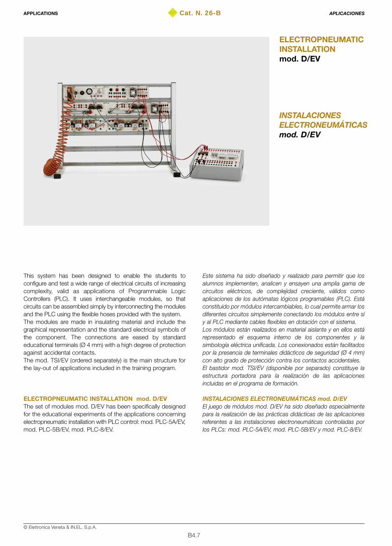
B4.7© Elettronica Veneta & IN.EL. S.p.A.
Cat. N. 26-B
INSTALACIONESELECTRONEUMÁTICASmod. D/EV
ELECTROPNEUMATICINSTALLATIONmod. D/EV
This system has been designed to enable the students toconfigure and test a wide range of electrical circuits of increasingcomplexity, valid as applications of Programmable LogicControllers (PLC). It uses interchangeable modules, so thatcircuits can be assembled simply by interconnecting the modulesand the PLC using the flexible hoses provided with the system.The modules are made in insulating material and include thegraphical representation and the standard electrical symbols ofthe component. The connections are eased by standardeducational terminals (Ø 4 mm) with a high degree of protectionagainst accidental contacts.The mod. TSI/EV (ordered separately) is the main structure forthe lay-out of applications included in the training program.
ELECTROPNEUMATIC INSTALLATION mod. D/EVThe set of modules mod. D/EV has been specifically designedfor the educational experiments of the applications concerningelectropneumatic installation with PLC control: mod. PLC-5A/EV,mod. PLC-5B/EV, mod. PLC-8/EV.
Este sistema ha sido diseñado y realizado para permitir que losalumnos implementen, analicen y ensayen una amplia gama decircuitos eléctricos, de complejidad creciente, válidos comoaplicaciones de los autómatas lógicos programables (PLC). Estáconstituido por módulos intercambiables, lo cual permite armar losdiferentes circuitos simplemente conectando los módulos entre síy al PLC mediante cables flexibles en dotación con el sistema.Los módulos están realizados en material aislante y en ellos estárepresentado el esquema interno de los componentes y lasimbología eléctrica unificada. Los conexionados están facilitadospor la presencia de terminales didácticos de seguridad (Ø 4 mm)con alto grado de protección contra los contactos accidentales.El bastidor mod. TSI/EV (disponible por separado) constituye laestructura portadora para la realización de las aplicacionesincluidas en el programa de formación.
INSTALACIONES ELECTRONEUMÁTICAS mod. D/EVEl juego de módulos mod. D/EV ha sido diseñado especialmentepara la realización de las prácticas didácticas de las aplicacionesreferentes a las instalaciones electroneumáticas controladas porlos PLCs: mod. PLC-5A/EV, mod. PLC-5B/EV y mod. PLC-8/EV.
APPLICATIONS APLICACIONES

B4.8© Elettronica Veneta & IN.EL. S.p.A.
TRAINING PROGRAM• Control of a cylinder using a monostable solenoid valve • Control of a cylinder using a bistable solenoid valve • Control of a cylinder using a monostable solenoid valve and
self-holding circuit• Temporary memory with prevalent set• Temporary memory with prevalent reset • Temporary binary counter for circuits with bistable solenoid valve• Temporary binary counter for circuits with monostable
solenoid valve • Permanent binary counter with bistable solenoid valve• Permanent binary counter for circuits with monostable
solenoid valve • Control of a sliding door• Semi-automatic control of a double-acting cylinder with
monostable solenoid valve • Semi-automatic control of a double-acting cylinder with
bistable solenoid valve • Electrical control of a cylinder with monostable solenoid valve
and anti-repetitivity circuit• Electrical control of a cylinder with bistable solenoid valve
and anti-repetitivity circuit• Electrical control of a cylinder with monostable solenoid
valve, pulse relay and anti-repetitivity circuit• Electrical control of a cylinder with bistable solenoid valve,
pulse relay and anti-repetitivity circuit• Automatic control of a cylinder with monostable solenoid valve and
stop push-button with return to a0 after completion of the cycle• Automatic control of a cylinder with bistable solenoid valve and
stop push-button with return to a0 after completion of the cycle• Automatic control of a cylinder with bistable solenoid valve
and stop push-button with immediate return to a0 • Automatic control with bistable solenoid valve, and stop and
emergency push-button with differentiated returns• Automatic control with bistable solenoid valve, stop and
emergency push-button with immediate return to a0 • Control of a cylinder with monostable solenoid valve and ON-
delay timer • Electrical diagrams relative to the use of the excitation ON-
delay timer, with monostable solenoid valve andinstantaneous contact
• Semi-automatic control of a cylinder with bistable directionalcontrol valve and ON-delay timer
• Semi-automatic control of a cylinder with solenoid directionalcontrol valve, ON-delay timer and exchange contact
• Semi-automatic motion control with limit-switch, timer andmonostable directional control valve
• Semi-automatic motion control with limit-switch, timer andbistable directional control valve
• Two-hand safety control
ELEMENTARY LOGIC FUNCTIONS ACTUATED WITHELECTRICAL FUNCTIONAL BLOCKS • Identity function (YES)• Inversion function (NOT)• Addition function (inclusive OR)• Exclusive OR • Product function (AND)• Inhibition function • Example of logic equations
PROGRAMA DE FORMACIÓN• Control de un cilindro por medio de electroválvula monoestable• Control de un cilindro por medio de electroválvula biestable• Control de un cilindro por medio de electroválvula monoestable
y circuito de automantenimiento• Memoria temporal con inserción prioritaria• Memoria temporal con puesta a cero prioritaria• Contador binario temporal para circuitos con electroválvula
biestable• Contador binario temporal para circuitos con electroválvula
monoestable• Contador binario permanente para circuitos con electroválvula
biestable• Contador binario permanente para circuitos con electroválvula
monoestable• Control para puerta corredera• Control semiautomático de un cilindro de doble efecto con
electroválvula monoestable• Control semiautomático de un cilindro de doble efecto con
electroválvula biestable• Control eléctrico de un cilindro con electroválvula monoestable
(antirrepetitividad)• Control eléctrico de un cilindro con electroválvula biestable
(antirrepetitividad)• Control eléctrico de un cilindro con electroválvula monoestable
y relé de impulsos (antirrepetitividad)• Control eléctrico de un cilindro con electroválvula biestable y relé
de impulsos (antirrepetitividad)• Control automático con electroválvula monoestable y pulsador
de parada con retorno en a0 tras haber acabado el ciclo• Control automático con electroválvula biestable y pulsador de
parada con retorno en a0 tras haber acabado el ciclo• Control automático con electroválvula biestable y pulsador de
parada con retorno en a0 inmediato• Control automático con electroválvula biestable, pulsador de
parada y emergencia con retornos diferenciados• Control automático con electroválvula biestable, pulsador de
parada y emergencia con retorno inmediato en a0• Control de un cilindro con electroválvula monoestable y
temporizador con retardo en la excitación• Diagramas eléctricos de utilización del temporizador con retardo en
la excitación, electroválvula monoestable y contacto instantáneo• Control semiautomático de un cilindro con distribuidor
biestable, retardo en la excitación• Control semiautomático de un cilindro, con distribuidor
biestable, retardo en la excitación y contacto de intercambio• Movimiento semiautomático con final de carrera, temporización
y distribuidor monoestable• Movimiento semiautomático con final de carrera, temporización
y distribuidor biestable• Control de seguridad de dos manos
FUNCIONES LÓGICAS ELEMENTALES REALIZADAS CONDIAGRAMAS ELÉCTRICOS FUNCIONALES• Función identidad (YES)• Función inversión (NOT)• Función suma (OR inclusivo)• OR exclusivo • Función producto (AND)• Función inhibición• Ejemplos de ecuaciones lógicas
APPLICATIONS APLICACIONES
B4.9© Elettronica Veneta & IN.EL. S.p.A.
INDUSTRIAL APPLICATIONS• Square-cycle with bistable solenoid valves• Square-cycle with monostable solenoid valves• Square-cycle with monostable solenoid valves and safety
and emergency circuits• Square-cycle with bistable solenoid valves, safety and
emergency circuits • "L"-cycle with bistable solenoid valves• "L"-cycle with bistable solenoid valves and semi-automatic
control circuits and anti-repetitivity circuits • "L"-cycle with monostable solenoid valves, automatic and
semi-automatic control circuits and anti-repetitivity condition
TECHNICAL SPECIFICATIONSThe set of modules to carry out the electropneumaticinstallation mod. D/EV consists of:• 1 Module type AZ-10
5 fuse-holders with sectionable fuses, 4/6 A• 1 Module type AZ-15
1 transformer, 115-230 / 12-24 V 50-60 Hz, 72 VA• 1 Module type AZ-42
1 time-delay relay, 1.5 - 30 s, 24-Vac coil• 4 Modules type AZ-43
1 auxiliary relay for industrial uses, 24-Vac coil • 2 Modules type AZ-44
3 push-buttons for industrial uses• 1 Module type AZ-80
1 pneumatic power supply set with pneumatic switch,pressure control, pressure gauge and 4-ways distributor
• 2 Modules type AZ-811 double-acting cylinder with electrical limit switches
• 1 Module type AZ-822 monostable solenoid valves, 5/2 - 24 Vac
• 1 Module type AZ-832 bistable solenoid valves, 5/2 - 24 Vac
• 1 Module type AZ-841 pulse relay (unipolar deviator), 24-Vac coil
ACCESSORIESFrame TSI/EV. It is carried out with aluminum and sheet steelsections, chemically treated and painted with epoxy paint. Theframe base is provided with feet needing no fixing element tothe table.Dimensions: 1000x500x800 mmWeight: 10 kg
• set of 50 cables with Ø 4-mm safety pins• 1 elongation for pneumatic supply with spiral pipe and quick
acting connections• 10 m Ø 4-mm Rilsam pipe• 1 extractor to remove the Rilsam pipe from the quick acting
connections
POWER SUPPLY230 V / PE 50-60 Hz
PNEUMATIC SUPPLYCompressed air, 20 l/min flow rate, max. pressure 8 bar
APLICACIONES INDUSTRIALES• Ciclo cuadrado con electroválvulas biestables• Ciclo cuadrado con electroválvulas monoestables• Ciclo cuadrado con electroválvulas monoestables y circuitos de
seguridad y emergencia• Ciclo cuadrado con electroválvulas biestables y circuitos de
seguridad y emergencia• Ciclo en "L" con electroválvulas biestables• Ciclo en "L" con electroválvulas biestables y circuitos de control
automático, semiautomático y condición de antirrepetitividad• Ciclo en "L" con electroválvulas monoestables y circuitos de control
automático, semiautomático y condición de antirrepetitividad.
CARACTERÍSTICAS TÉCNICASEl juego de módulos para realizar las instalacioneselectroneumáticas mod. D/EV está constituido por:• 1 Módulo tipo AZ-10
5 portafusibles de panel con fusibles extraíbles 4/6 A• 1 Módulo tipo AZ-15
1 transformador 115-230 /12-24 V 50-60 Hz, 72 VA• 1 Módulo tipo AZ42
1 temporizador 1,5 - 30 s, bobina 24 Vca• 4 Módulos tipo AZ43
1 relé auxiliar para usos industriales, bobina 24 Vca• 2 Módulos tipo AZ 44
3 pulsadores para usos industriales• 1 Módulo tipo AZ80
alimentación neumática con interruptor neumático, regulador depresión, manómetro y distribuidor de 4 vías
• 2 Módulos tipo AZ811 cilindro de doble efecto, con finales de carrera eléctricos
• 1 ModulotipoAZ822 electroválvulas monoestables 5/2 - 24 Vca
• 1 Módulo tipo AZ832 electroválvulas biestables 5/2 - 24 Vca
• 1 Módulo tipo AZ841 relé de impulsos (desviador unipolar) bobina 24 Vca
ACCESORIOSBastidor mod. TSI/EV. Está realizado en aluminio perfilado y chapa deacero tratados químicamente y pintados con varias manos de barnizepoxi. La base del bastidor está provista de patas transversales y norequiere dispositivos de sujeción a la mesa de soporte.Dimensiones: 1100x500x800 mmPeso: 10 kg
• juego de 50 cables con terminales de seguridad Ø 4 mm• extensión de cable para alimentación neumática con tubo
espiralado y uniones con acoplamiento rápido• 10 metros de tubo rilsam Ø 4 mm• extractor para extraer el tubo de las uniones con acoplamiento
rápido
ALIMENTACIÓN ELÉCTRICA230 V / PE 50-60 Hz
ALIMENTACIÓN NEUMÁTICAAire comprimido, caudal 20 l/min. Presión máx.: 8 bares
APPLICATIONS APLICACIONES

B4.10© Elettronica Veneta & IN.EL. S.p.A.
SUGGESTED ACCESSORIESSILENCED COMPRESSOR, mounted on revolving wheels andcomplete with air tank, overpressure valve and pressurereducer with quick acting connection M.12 MINI 1/4".
TECHNICAL CHARACTERISTICS• Capacity: 20 l• Flow rate: 55 l/min• Pressure: 7 bar• Motor power: 0.5 kW• Rpm: 1400 rpm• Noise: < 57 dB• Power supply: 230 V single-phase – 50-60 Hz• Automatic thermal protection • Dimensions: 650x350x750 mm• Weight: 30 kg
THEORETICAL-EXPERIMENTAL HANDBOOKS• Theoretical-application handbook for equipment presentation• Handbook for the applications with mod. PLC-5A/EV,
mod. PLC-5B/EV, mod. PLC-8/EV
ACCESORIOS RECOMENDADOSCOMPRESOR SILENCIADO, el compresor está montado sobreruedas giratorias y está provisto de depósito, válvula de sobrepresióny reductor de presión con acoplamiento rápido M.12 MINI 1/4".
CARACTERÍSTICAS TÉCNICAS• Capacidad: 20 l• Caudal: 55 l/min• Presión: 7 bares• Potencia del motor: 0,5 kW• Velocidad de rotación del motor: 1.400 r.p.m.• Nivel de ruido: < 57 dB• Alimentación: 230 V monofásica – 50-60 Hz• Protección térmica automática• Dimensiones: 650x350x750 mm• Peso: 30 kg
TEXTOS TEÓRICO-PRÁCTICOS• Manual teórico-aplicativo de presentación del equipo• Manual de las aplicaciones con PLC-5A/EV, PLC-5B/EV, PLC-8/EV
APPLICATIONS APLICACIONES
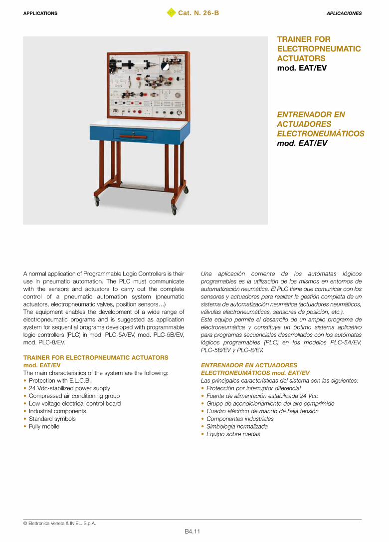
B4.11© Elettronica Veneta & IN.EL. S.p.A.
Cat. N. 26-B
ENTRENADOR ENACTUADORESELECTRONEUMÁTICOSmod. EAT/EV
TRAINER FORELECTROPNEUMATICACTUATORSmod. EAT/EV
A normal application of Programmable Logic Controllers is theiruse in pneumatic automation. The PLC must communicatewith the sensors and actuators to carry out the completecontrol of a pneumatic automation system (pneumaticactuators, electropneumatic valves, position sensors…)The equipment enables the development of a wide range ofelectropneumatic programs and is suggested as applicationsystem for sequential programs developed with programmablelogic controllers (PLC) in mod. PLC-5A/EV, mod. PLC-5B/EV,mod. PLC-8/EV.
TRAINER FOR ELECTROPNEUMATIC ACTUATORSmod. EAT/EVThe main characteristics of the system are the following:• Protection with E.L.C.B.• 24 Vdc-stabilized power supply• Compressed air conditioning group • Low voltage electrical control board • Industrial components• Standard symbols• Fully mobile
Una aplicación corriente de los autómatas lógicosprogramables es la utilización de los mismos en entornos deautomatización neumática. El PLC tiene que comunicar con lossensores y actuadores para realizar la gestión completa de unsistema de automatización neumática (actuadores neumáticos,válvulas electroneumáticas, sensores de posición, etc.).Este equipo permite el desarrollo de un amplio programa deelectroneumática y constituye un óptimo sistema aplicativopara programas secuenciales desarrollados con los autómataslógicos programables (PLC) en los modelos PLC-5A/EV,PLC-5B/EV y PLC-8/EV.
ENTRENADOR EN ACTUADORESELECTRONEUMÁTICOS mod. EAT/EVLas principales características del sistema son las siguientes:• Protección por interruptor diferencial• Fuente de alimentación estabilizada 24 Vcc• Grupo de acondicionamiento del aire comprimido• Cuadro eléctrico de mando de baja tensión• Componentes industriales• Simbología normalizada• Equipo sobre ruedas
APPLICATIONS APLICACIONES

B4.12© Elettronica Veneta & IN.EL. S.p.A.
TRAINING PROGRAM• Boolean functions • Manual controls• Semiautomatic and automatic controls• Emergency controls • Sequential cycles • Development of sequential cycles of different complexity with
PLC which can be connected to the Personal Computer
TECHNICAL SPECIFICATIONSElectropneumatic units:• Rodless double-acting cylinder controlled by 2 3/2 single
solenoid valves, including direct reflection photoelectricposition transducer with analog output
• Oscillating pneumatic motor with a 5/2 double-solenoid valveand 2 electrical limit switches with pressure drop
• Bidirectional DC electrical motor with optoelectronic transducer• Single-acting cylinder including 3/2 single-solenoid valve,
capacitive and magnetic limit switches• Double-acting rod cylinder including 5/3 closed-center double-
solenoid valve and 4 limit switches: electromechanical,proximity, inductive, optical reflection type, light barrier fiberoptics
• Electrical control board with pushbuttons and relays• Electrical cables of different length
DIMENSIONS and WEIGHT100x70x170 cm – 85 kg
POWER SUPPLYElectrical• 230 V – 50/60 Hz (115 V upon request)Pneumatic• Compressed air: 6 bar, 50 nl/min max.
REQUIRED INSTRUMENTS• Multimeter
THEORETICAL-EXPERIMENTAL HANDBOOKS • Theoretical-experimental handbook with guide to the exercises• Installation, use and maintenance handbook
PROGRAMA DE FORMACIÓN• Funciones en lógica booleana• Mandos manuales• Mandos semiautomáticos y automáticos• Mandos de emergencia• Ciclos secuenciales• Desarrollo de ciclos secuenciales, de diferentes complejidades,
con el auxilio de autómatas lógicos programables (PLC) quepueden conectarse a ordenadores personales
CARACTERÍSTICAS TÉCNICASGrupos electroneumáticos:• Cilindro de doble efecto, sin vástago, gobernado por 2
electroválvulas 3/2 monosolenoides, completo detransductor de posición fotoeléctrico por reflexión directacon salida analógica
• Motor neumático oscilante con electroválvula 5/2 bisolenoidey 2 finales de carrera eléctricos por caída de presión
• Motor eléctrico de c.c., bidireccional con transductoroptoelectrónico
• Cilindro de simple efecto con electroválvula 3/2monosolenoide, final de carrera de proximidad capacitivo,final de carrera de proximidad magnético
• Cilindro de doble efecto, con vástago atravesador,electroválvula 5/3 con centros cerrados, bisolenoide,completo de 4 finales de carrera: electromecánico, deproximidad inductivo, fotoeléctrico por reflexión, fotoeléctricoa obstrucción por fibra óptica
• Cuadro eléctrico con pulsadores y relés• Cables eléctricos de longitudes diferentes
DIM. y PESO100x70x170 cm – 85 kg
ALIMENTACIÓNEléctrica• 230 V – 50/60 Hz (115 V bajo pedido)Neumática• Aire comprimido: 6 bares, 50 nl/min máx.
INSTRUMENTACIÓN REQUERIDA• Multímetro
TEXTOS TEÓRICO-PRÁCTICOS• Manual teórico-práctico con guía para la realización de las
prácticas• Manual de instalación, uso y mantenimiento
APPLICATIONS APLICACIONES
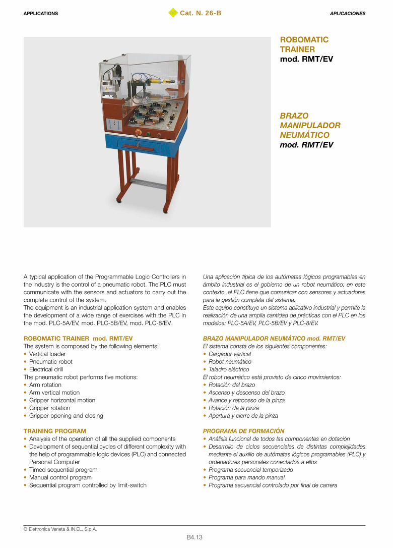
B4.13© Elettronica Veneta & IN.EL. S.p.A.
Cat. N. 26-B
BRAZOMANIPULADORNEUMÁTICOmod. RMT/EV
ROBOMATICTRAINERmod. RMT/EV
A typical application of the Programmable Logic Controllers inthe industry is the control of a pneumatic robot. The PLC mustcommunicate with the sensors and actuators to carry out thecomplete control of the system.The equipment is an industrial application system and enablesthe development of a wide range of exercises with the PLC inthe mod. PLC-5A/EV, mod. PLC-5B/EV, mod. PLC-8/EV.
ROBOMATIC TRAINER mod. RMT/EVThe system is composed by the following elements:• Vertical loader• Pneumatic robot• Electrical drill The pneumatic robot performs five motions:• Arm rotation• Arm vertical motion • Gripper horizontal motion • Gripper rotation• Gripper opening and closing
TRAINING PROGRAM• Analysis of the operation of all the supplied components• Development of sequential cycles of different complexity with
the help of programmable logic devices (PLC) and connectedPersonal Computer
• Timed sequential program • Manual control program • Sequential program controlled by limit-switch
Una aplicación típica de los autómatas lógicos programables enámbito industrial es el gobierno de un robot neumático; en estecontexto, el PLC tiene que comunicar con sensores y actuadorespara la gestión completa del sistema.Este equipo constituye un sistema aplicativo industrial y permite larealización de una amplia cantidad de prácticas con el PLC en losmodelos: PLC-5A/EV, PLC-5B/EV y PLC-8/EV.
BRAZO MANIPULADOR NEUMÁTICO mod. RMT/EVEl sistema consta de los siguientes componentes:• Cargador vertical• Robot neumático• Taladro eléctricoEl robot neumático está provisto de cinco movimientos:• Rotación del brazo• Ascenso y descenso del brazo• Avance y retroceso de la pinza• Rotación de la pinza• Apertura y cierre de la pinza
PROGRAMA DE FORMACIÓN• Análisis funcional de todos las componentes en dotación• Desarrollo de ciclos secuenciales de distintas complejidades
mediante el auxilio de autómatas lógicos programables (PLC) yordenadores personales conectados a ellos
• Programa secuencial temporizado• Programa para mando manual• Programa secuencial controlado por final de carrera
APPLICATIONS APLICACIONES

B4.14© Elettronica Veneta & IN.EL. S.p.A.
TECHNICAL SPECIFICATIONS• Vertical loader with proximity sensor • Pneumatic robot with cylindrical geometry • Electrical drill with manual and automatic control• Pneumatic supply section• Electropneumatic power section • Shock-resistant methacrylate safety protection • Controllable and programmable via PLC• Controllable and programmable via Personal Computer Components of the supply section• 2 air-conditioning groups • 2 pressure gauges• 1 3/2 switch• 1 displayComponents of the power section• 3 5/2 single-solenoid valves• 3 3/2 single-solenoid valves• 3 silencers• 4 regulators-silencersComponents of the control section• 1 optical sensor• 8 electrical threshold sensorsAccessories• Drill bits• Set of spanners• Electrical cables• Components for drilling
DIMENSIONS and WEIGHT70x70x190 cm – 90 kg
POWER SUPPLYElectrical• 230V – 50/60 Hz, 200 VA (115V upon request)Pneumatic• Compressed air 6 bar 100 Nl/min max.
THEORETICAL-EXPERIMENTAL HANDBOOKS• Theoretical-experimental handbook with guide to the exercises• Installation, use and maintenance handbook
CARACTERÍSTICAS TÉCNICAS• Cargador vertical con sensor de proximidad• Robot neumático con geometría cilíndrica• Taladro eléctrico con mando manual y automático• Sector de alimentación neumática• Sector de potencia electroneumática• Protección de seguridad en metacrilato anti-impacto• Gobernable y programable por medio de autómata (PLC)• Gobernable y programable por medio de ordenador personal Componentes sector alimentación• 2 grupos de acondicionamiento• 2 manómetros• 1 interruptor 3/2• 1 visualizadorComponentes sector potencia• 3 electroválvulas 5/2 monosolenoides• 3 electroválvulas 3/2 monosolenoides• 3 silenciadores• 4 reguladores-silenciadoresComponentes sector de mando• 1 sensor óptico• 8 detectores eléctricos con umbral de presiónAccesorios en dotación• Brocas para taladro• Juego de llaves• Cables eléctricos• Componentes por taladrar
DIM. y PESO70x70x190 cm – 90 kg
ALIMENTACIÓNEléctrica:• 230 V – 50/60 Hz, 200 VA (115 V bajo pedido)Neumática:• Aire comprimido: 6 bares, 100 Nl/min máx.
TEXTOS TEÓRICO-PRÁCTICOS• Manual teórico-práctico con guía para la realización de las
prácticas• Manual de instalación, uso y mantenimiento
APPLICATIONS APLICACIONES

B4.15© Elettronica Veneta & IN.EL. S.p.A.
Cat. N. 26-B
ASCENSORDE 3 PISOSmod. HM400/EV
3-FLOOR LIFTmod. HM400/EV
The control of a lift is one of the most used applications ofProgrammable Logic Controllers, in the domestic field. In theseapplications, the PLC must communicate with sensors andactuators for the system complete control: motion, multiplecalls, stops, alarms, etc.In this context, the 3-floor lift mod. HM400/EV has been carriedout to reproduce on a small scale all operations of a real lift, forthe development of a wide range of exercises with the PLC inmod. PLC-5A/EV, mod. PLC-5B/E and mod. PLC-8/EV.
3-FLOOR LIFT mod. HM400/EVThe 3-floor lift mod. HM400/EV mainly consists of a lightmechanical structure, reproducing a building on a reducedscale, where a small lift can run 3 floors moved by a DC motor.On a plastic mask, the front side of the system shows thecontrols of each plane and those inside the lift for the simulationof the operation. The lift opening is simulated by 3 small doors(one for floor). Many sensors detect the presence of the lift atthe floor, the opening of its door and the two positions (upperand lower) of extra-stroke. The controls inside the lift cabininclude the STOP and ALARM situations.On the rear side of the system mod. HM400/EV a panel ininsulating material reports the silk screen diagram of theelectrical installation for the lift control. The safety connectorson the panel enable the PLC connection to the system mod.HM400/EV for the development of programs concerning thecontrol of a lift in all possible ways.
TRAINING PROGRAM The automation process with the 3-floor lift mod. HM400/EVenables the theoretical analysis and the experiments on thefollowing main exercises:• Microswitches• Relays• ON/OFF drives of a DC motor• Lift systems
Una de las aplicaciones más difundidas de los autómataslógicos programables, en ámbito urbano, es la gestión de unascensor. En estas aplicaciones el PLC tiene que comunicarcon sensores y actuadores para la gestión completa delsistema: movimiento, llamada múltiple, parada, alarmas, otros.En este contexto el ascensor de tres pisos mod. HM400/EV hasido realizado para reproducir en miniatura todas lasfuncionalidades de un ascensor real, para la realización de unaamplia cantidad de prácticas con el PLC en los modelos:PLC-5A/EV,PLC-5B/EV y PLC-8/EV.
ASCENSOR DE TRES PISOS mod. HM400/EVEl ascensor de tres pisos mod. HM400/EV básicamente estáconstituido por una estructura mecánica, liviana, quereproduce en escala reducida un edificio en el cual un pequeñoascensor puede recorrer tres pisos accionado por un motor deCC. El flanco delantero del sistema muestra, en una máscara deplástico, los mandos de cada piso y las partes internas alascensor para simular el funcionamiento; la apertura delascensor es simulada por tres puertas pequeñas (una por piso).Una variedad de sensores detecta la presencia en el piso delascensor, la apertura de la puerta y las dos posiciones (superiore inferior) de extracarrera. Los mandos internos a la cabina delascensor contemplan las situaciones de PARADA y ALARMA.En el flanco trasero del sistema mod. HM400/EV se encuentraun panel en material aislante que lleva representado en serigrafíael esquema sinóptico de la instalación eléctrica para el gobiernodel ascensor. Los conectores de seguridad presentes en el panelpermiten el conexionado del PLC con el sistema mod.HM400/EV para el desarrollo de programas inherentes algobierno de un ascensor en todas las variantes posibles.
PROGRAMA DE FORMACIÓN El proceso de automatización con el ascensor de tres pisosmod. HM400/EV permite el análisis teórico y la realización deprácticas sobre los siguientes principales temas:• Microinterruptores• Relés• Accionamientos todo/nada de un motor eléctrico de c.c.• Sistemas de ascensor
APPLICATIONS APLICACIONES
B4.16© Elettronica Veneta & IN.EL. S.p.A.
Exercises with PLC mod. PLC-5A/EV, mod. PLC-5B/EV,mod. PLC-8/EV:• General control of a lift • Control of a lift with multiple call• Control of a lift with multiple call and memory• Emergencies
TECHNICAL SPECIFICATIONS• Sheet steel container, chemically treated and painted with
epoxy paint • Side panel, in insulating material, with silk screen
representation of the electrical contacts• 3 floors• 3 doors for the lift opening and closing simulation• 1 DC motor for the lift motion • 3 limit switch microswitches for the 3 floors• 2 extra-stroke sensors• 38 safety terminals of which 2 for 24-Vdc supply of the motor
control relays. (The power supply is provided with the PLC )• 2 relays for UP/DOWN control of the lift motor • 1 signaling LED for power supply presence.1st floor • UP command with green LED signaling• Green LED signaling: 1 ST FLOOR• Green LED signaling: DOOR CLOSED2nd floor• UP and DOWN commands with green LED signaling• Green LED signaling: 2 ND FLOOR• Green LED signaling: DOOR CLOSED3rd floor• DOWN command with green LED signaling• Green LED signaling: 3 RD FLOOR• Green LED signaling: DOOR CLOSEDInside the lift:Commands:- 3 RD FLOOR with green LED - 2 ND FLOOR with green LED - 1 ST FLOOR with green LED - STOP with green LED - ALARM with red LED
Accessories• 50 Ø 4-mm connection cables • Single-phase power supply cable
DIMENSIONS415x450x300 mm
WEIGHT 5 kg
POWER SUPPLY115/230 Vac ±10% – 50/60 Hz
THEORETICAL-EXPERIMENTAL HANDBOOKS• Theoretical-application handbook for equipment presentation
and guide to the exercises
Prácticas con los PLCs mod. PLC-5A/EV,mod. PLC-5B/EV, mod. PLC-8/EV• Gobierno general de un ascensor• Gobierno de un ascensor con llamada múltiple• Gobierno de un ascensor con llamada múltiple y memoria• Casos de emergencia
CARACTERÍSTICAS TÉCNICAS• Estructura en aluminio, tratada químicamente y pintada con
barniz epoxi• Panel trasero realizado en material aislante con esquema
sinóptico serigrafiado de los contactos eléctricos• 3 pisos• 3 puertas para la simulación de la apertura y el cierre del ascensor• 1 motor de corriente continua para el movimiento del ascensor• 3 microinterruptores con final de carrera para los tres pisos• 2 sensores de extracarrera• 38 bornes de seguridad, de los cuales 2 para la alimentación
a 24 Vcc de los relés de mando del motor (la alimentación esproporcionada por el PLC)
• 2 relés para el mando UP/DOWN del motor del ascensor• 1 LED de señalización presencia alimentación.1° piso• Mando UP con señalización mediante LED verde• Señalización con LED verde: 1 ST FLOOR• Señalización con LED verde: DOOR CLOSED2° piso• Mandos UP y DOWN con señalización mediante LED verde• Señalización con LED verde: 2 ND FLOOR• Señalización con LED verde: DOOR CLOSED3° piso• Mando DOWN con señalización mediante LED verde• Señalización con LED verde: 3 RD FLOOR• Señalización con LED verde: DOOR CLOSEDParte interior de ascensor:Mandos:- 3 RD FLOOR con LED verde - 2 ND FLOOR con LED verde- 1 ST FLOOR con LED verde- STOP con LED verde- ALARM con LED rojo
Accesorios• 50 cables de conexión Ø 4 mm• Cable de alimentación monofásica
DIMENSIONES415x450x300 mm
PESO5 kg
ALIMENTACIÓN115/230 Vca ±10% – 50/60 Hz
TEXTOS TEÓRICO-PRÁCTICOS• Manual teórico-aplicativo de presentación del equipo y guía
para las aplicaciones
APPLICATIONS APLICACIONES
➪➪
➪
➪
➪
➪
➪
➪
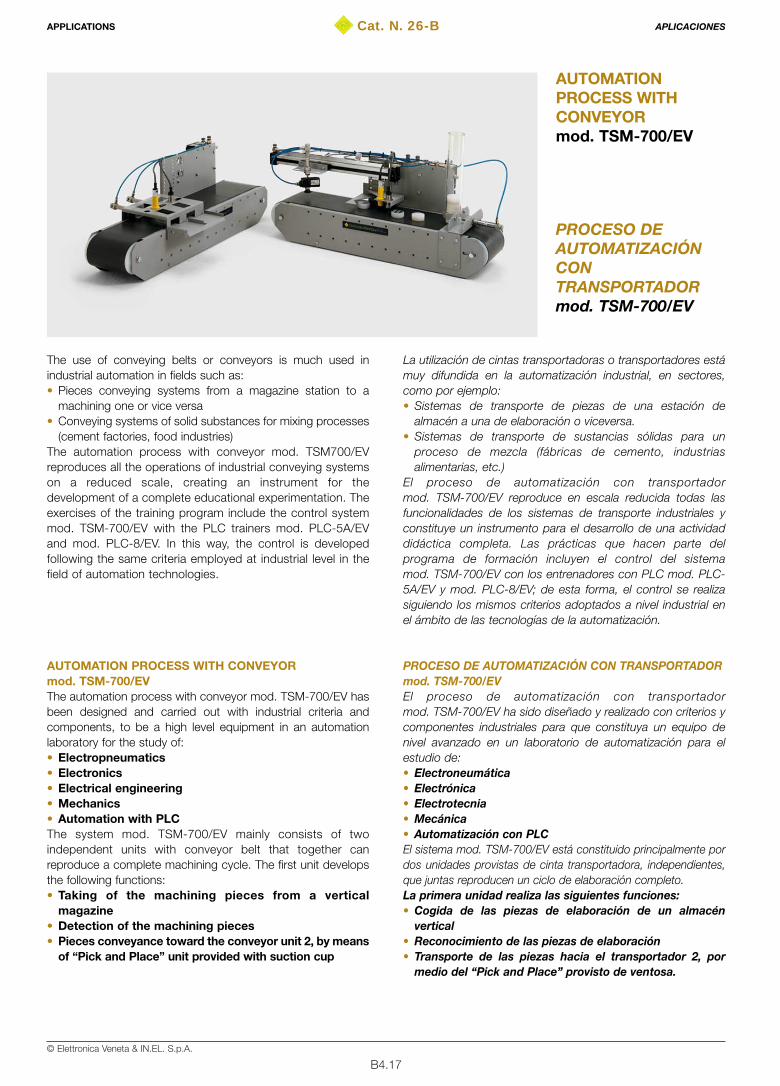
B4.17© Elettronica Veneta & IN.EL. S.p.A.
Cat. N. 26-B
PROCESO DEAUTOMATIZACIÓNCONTRANSPORTADORmod. TSM-700/EV
AUTOMATIONPROCESS WITHCONVEYORmod. TSM-700/EV
The use of conveying belts or conveyors is much used inindustrial automation in fields such as:• Pieces conveying systems from a magazine station to a
machining one or vice versa • Conveying systems of solid substances for mixing processes
(cement factories, food industries)The automation process with conveyor mod. TSM700/EVreproduces all the operations of industrial conveying systemson a reduced scale, creating an instrument for thedevelopment of a complete educational experimentation. Theexercises of the training program include the control systemmod. TSM-700/EV with the PLC trainers mod. PLC-5A/EVand mod. PLC-8/EV. In this way, the control is developedfollowing the same criteria employed at industrial level in thefield of automation technologies.
AUTOMATION PROCESS WITH CONVEYORmod. TSM-700/EVThe automation process with conveyor mod. TSM-700/EV hasbeen designed and carried out with industrial criteria andcomponents, to be a high level equipment in an automationlaboratory for the study of:• Electropneumatics• Electronics• Electrical engineering• Mechanics• Automation with PLCThe system mod. TSM-700/EV mainly consists of twoindependent units with conveyor belt that together canreproduce a complete machining cycle. The first unit developsthe following functions:• Taking of the machining pieces from a vertical
magazine• Detection of the machining pieces • Pieces conveyance toward the conveyor unit 2, by means
of “Pick and Place” unit provided with suction cup
La utilización de cintas transportadoras o transportadores estámuy difundida en la automatización industrial, en sectores,como por ejemplo:• Sistemas de transporte de piezas de una estación de
almacén a una de elaboración o viceversa. • Sistemas de transporte de sustancias sólidas para un
proceso de mezcla (fábricas de cemento, industriasalimentarias, etc.)
El proceso de automatización con transportadormod. TSM-700/EV reproduce en escala reducida todas lasfuncionalidades de los sistemas de transporte industriales yconstituye un instrumento para el desarrollo de una actividaddidáctica completa. Las prácticas que hacen parte delprograma de formación incluyen el control del sistemamod. TSM-700/EV con los entrenadores con PLC mod. PLC-5A/EV y mod. PLC-8/EV; de esta forma, el control se realizasiguiendo los mismos criterios adoptados a nivel industrial enel ámbito de las tecnologías de la automatización.
PROCESO DE AUTOMATIZACIÓN CON TRANSPORTADORmod. TSM-700/EVEl proceso de automatización con transportadormod. TSM-700/EV ha sido diseñado y realizado con criterios ycomponentes industriales para que constituya un equipo denivel avanzado en un laboratorio de automatización para elestudio de:• Electroneumática• Electrónica• Electrotecnia• Mecánica• Automatización con PLCEl sistema mod. TSM-700/EV está constituido principalmente pordos unidades provistas de cinta transportadora, independientes,que juntas reproducen un ciclo de elaboración completo.La primera unidad realiza las siguientes funciones:• Cogida de las piezas de elaboración de un almacén
vertical• Reconocimiento de las piezas de elaboración• Transporte de las piezas hacia el transportador 2, por
medio del “Pick and Place” provisto de ventosa.
APPLICATIONS APLICACIONES
B4.18© Elettronica Veneta & IN.EL. S.p.A.
The second conveyor unit carries out:• Machining pieces detection • Pieces deposit in final tool magazineThe components present on the system mod. TSM-700/EV are:• Electropneumatic (single- and double-acting cylinders,
solenoid valves, depression unit)• Electrical (single-phase asynchronous motors, relays)• Electronic (inductive, capacitive, magnetic sensors)• Mechanic (motion reducing systems)Each unit has a control board with front panel reporting theelectrical diagram of the contacts and the actuators. On thepanel, there are connectors for connection to the controlsystem. In this way, the system mod. TSM-700/EV can beconsidered an application of the trainers with PLC mod. PLC-5A/EV and mod. PLC-8/EV. The I/O interfacing of theautomation process with conveyor mod. TSM-700/EV to thetrainers is made via accessory connection terminals. Thecontrol of the whole system is performed by the user from apushbutton board connectable to the PLC. This includes thepushbuttons, with signaling lamp for START, STOP,EMERGENCY and others which function can be defined bythe application. In this way, it is possible to develop a widerange of programming examples for the machining cycle,without changing the structure of the system.The development of the exercises is supported by thetheoretical-experimental handbooks provided with theautomation process with conveyor mod. TSM-700/EV.
TRAINING PROGRAMThe automation process with conveyor mod. TSM-700/EVenables the theoretical analysis and the experiments on thefollowing main exercises:• Principles of electropneumatics• Pressure regulators • Monostable solenoid valves • Single-acting cylinders• Double-acting cylinders • Manipulation unit with suction cup• ON/OFF electrical drives of single-phase asynchronous
motors • Mechanical reducers for the motion • Capacitive sensors • Inductive sensors • Magnetic sensorsExercises with PLC trainer mod. PLC-5A/EV andmod. PLC-8/EV• I/O control of a PLC for interfacing to sensors and actuators • Software writing starting from the basic sequences of the cycle• State representation of the system • Manual control of a production cycle • Semi-automatic control of a production cycle • Automatic control of a production cycle • State initialization of the plant • Technical safety of the plant • Plant control in case of STOP• Plant control in case of EMERGENCY• Production optimization
La segunda unidad realiza:• Reconocimiento de las piezas de elaboración• Depósito de las piezas en el almacén finalLos componentes presentes en el sistema mod. TSM-700/EV sonde tipo:• Electroneumático (cilindros de simple efecto y de doble
efecto, electroválvulas, unidad de depresión)• Eléctrico (motores asíncronos monofásicos, relés)• Electrónico (sensores inductivos, capacitivos, magnéticos)• Mecánico (sistemas de reducción del movimiento)Cada unidad presenta un cuadro de mando con panel delanteroen el cual está representado el diagrama eléctrico de los contactosy los actuadores. En el cuadro están presentes tambiénconectores para el conexionado con el sistema de control. Bajoesta óptica, el sistema mod. TSM-700/EV ha sido concebido paraque constituya una aplicación de los entrenadores en PLCmod. PLC-5A/EV y mod. PLC-8/EV. El interfaz de las E/S delsistema mod. TSM-700/EV con los entrenadores se realiza através de cables de conexión. El mando de todo el sistema esrealizado por el operador mediante una caja de pulsadores quepuede conectarse al PLC. En la misma están presentespulsadores, con lámpara piloto de señalización, paraENCENDIDO, PARADA, EMERGENCIA y otros cuya funciónpuede definirse en base a la aplicación; de esta forma, es posibledesarrollar una gran variedad de ejemplos de programación delciclo de elaboración, sin modificar la estructura del sistema.La realización de las prácticas está soportado por la consulta delos manuales teórico-prácticos en dotación con el proceso deautomatización mod. TSM-700/EV.
PROGRAMA DE FORMACIÓNEl proceso de automatización con transportador mod. TSM-700/EVpermite el análisis teórico y la realización de prácticas sobre lassiguientes principales temas:• Principios de electroneumática• Reguladores de presión• Electroválvulas monoestables• Cilindros de simple efecto• Cilindros de doble efecto• Unidad de manipulación con ventosa• Accionamientos eléctricos todo/nada de motores asíncronos
monofásicos• Reductores mecánicos del movimiento• Sensores capacitivos• Sensores inductivos• Sensores magnéticosPrácticas con los entrenadores en PLC mod. PLC-5A/EV ymod. PLC-8/EV• Gobierno E/S de un PLC para el interfaz con sensores y
actuadores • Escritura del software a partir de las secuencias básicas del ciclo• Representación por estados del sistema• Gobierno manual de un ciclo de producción• Gobierno semiautomático de un ciclo de producción• Gobierno automático de un ciclo de producción• Iniciación del estado de la instalación• Seguridad técnica de la instalación• Gobierno de la instalación en caso de PARADA• Gobierno de la instalación en caso de EMERGENCIA• Optimización de la producción
APPLICATIONS APLICACIONES
B4.19© Elettronica Veneta & IN.EL. S.p.A.
TECHNICAL SPECIFICATIONS
CONVEYOR UNIT No. 1• Sheet steel structure, chemically treated and painted with
epoxy paint • Conveyor belt in linenized rubber • Teflon rolls, complete with iron support pin• 230-Vac single-phase asynchronous motor with motor
reducer. Rotation speed of about 15 RPM• Mechanical transmission system for the motion at the output
of the belt conveyor roll reducer
Pieces container• Transparent Plexiglas tube • Mechanical support for piece container • Single-acting cylinders
Pieces detection• Inductive sensors • Capacitive sensors
Horizontal motion mechanism• Rodless cylinder • Magnetic limit switches for rodless cylinder• Bidirectional flow regulators
Pieces lifter• Mechanical support for lifter• Single-acting cylinders• “Pick and Place” unit provided with suction cup
Electropneumatic control• Support for solenoid valves• Packet with 5 3/2 monostable solenoid valves with 24-Vdc
electrical control• Bidirectional flow regulators
Electrical control board• Plastic external structure• Panel in insulating material with silk screen diagram of the
electrical contacts• Red and black safety connectors • Single-phase power supply socket • Protection fuses• Cable for networked single-phase power supply
DIMENSIONS: 900x300x400 mm
WEIGHT: 10 kg
CONVEYOR UNIT No. 2• Sheet steel structure, chemically treated and painted with
epoxy paint • Linenized rubber conveyor belt • Teflon rolls, complete with iron support pin• 230-Vac single-phase asynchronous motor with motor
reducer. Rotation speed of about 15 RPM• Mechanical transmission system for the motion at the output
of the belt conveyor roll reducer• Stainless steel guide to canalize the pieces under the piece
detection and expulsion equipment
CARACTERÍSTICAS TÉCNICAS
UNIDAD CON CINTA TRANSPORTADORA N° 1• Estructura en acero, tratada químicamente y pintada con barniz
epoxi • Cinta transportadora en caucho revestido en tela• Rodillos en teflón, completos de perno en hierro de soporte • Motor asíncrono monofásico de 230 Vca con motorreductor.
Velocidad de rotación aprox. 15 r.p.m.• Sistema de transmisión mecánica, del movimiento, desde la
salida del reductor hasta el rodillo de arrastre de la cinta
Contenedor de piezas• Tubo en plexiglás transparente• Soporte mecánico para el contenedor de piezas• Cilindros de simple efecto
Reconocimiento de las piezas• Sensores inductivos• Sensores capacitivos
Mecanismo de traslación horizontal• Cilindro sin vástago• Finales de carrera magnéticos para cilindro sin vástago• Reguladores de flujo bidireccionales
Elevador de piezas• Soporte mecánico para elevador• Cilindros de simple efecto• Unidad “Pick and Place” provista de ventosa
Control electroneumático• Soporte para electroválvulas• Juego de cinco electroválvulas monoestables 3/2 con mando
eléctrico de 24 Vcc• Reguladores de flujo bidireccionales
Cuadro eléctrico de mando• Estructura exterior en material plástico • Panel en material aislante con esquema sinóptico de los
contactos eléctricos• Conectores de seguridad rojos y negros• Toma de alimentación monofásica• Fusibles de protección• Cable para la alimentación monofásica desde red
DIMENSIONES: 900x300x400 mm
PESO: 10 kg
UNIDAD CON CINTA TRANSPORTADORA N° 2• Estructura en acero, tratada químicamente y pintada con
barniz epoxi • Cinta transportadora en caucho revestido en tela• Rodillos en teflón, completos de perno metálico de soporte • Motor asíncrono monofásico de 230 Vca con motorreductor.
Velocidad de rotación aprox. 15 r.p.m.• Sistema de transmisión mecánica del movimiento, desde la
salida del reductor hasta el rodillo de arrastre de la cinta• Guía metálica en acero inoxidable para encanalar las piezas
debajo del aparato de reconocimiento y expulsión de la pieza
APPLICATIONS APLICACIONES
B4.20© Elettronica Veneta & IN.EL. S.p.A.
Piece detection and expulsion • Mechanical support for limit switches and cylinders • Inductive sensors • Capacitive sensors• Single-acting cylinders with pieces pusher
Electropneumatic control• Support for solenoid valves• Packet with 2 3/2 monostable solenoid valves with 24-Vdc
electrical control• Bidirectional flow regulators
Electrical control board• Plastic external structure• Panel in insulating material with silk screen diagram of the
electrical contacts• Red and black safety connectors • Single-phase power supply socket • Protection fuses• Cable for single-phase power supply from network
DIMENSIONS: 700x370x280 mm
WEIGHT: 10 kg
CONTROL PUSHBUTTON BOARDThe control pushbutton board of the conveyor system can beconnected to the PLC with accessory cables and is composed of:• Plastic envelope with front panel reporting the silk screen
diagram of the electrical contacts• Red and black safety connectors • 2 pushbuttons with green signaling lamp. NO contact• 2 pushbuttons with red signaling lamp. NC contact• Emergency pushbutton with mechanical self-hold complete
with NC contact
ELECTRICAL POWER SUPPLY Separate power supply for each conveyor unit:Single-phase 115/230 Vac ±10% – 50/60 Hz
PNEUMATIC POWER SUPPLYThe two conveyor units need to be powered pneumatically viaan external compressor.Compressed air pressure: from 4 to 6 bar.
ACCESSORIES• Connection cables: Ø 4 mm, 2-m length• Connection cables: Ø 4 mm, 250-mm length
THEORETICAL-EXPERIMENTAL HANDBOOKS • Theoretical-application handbook for equipment presentation
and guide to the exercises
Reconocimiento y expulsión de la pieza• Soporte mecánico para final de carrera y cilindros• Sensores inductivos• Sensores capacitivos• Cilindros de simple efecto con dispositivo de empuje de las piezas
Control electroneumático• Soporte para electroválvulas• Juego de dos electroválvulas monoestables 3/2 con mando
eléctrico de 24 Vcc• Reguladores de flujo bidireccionales
Cuadro eléctrico de mando• Estructura exterior en material plástico• Panel en material aislante con esquema sinóptico de los
contactos eléctricos• Conectores de seguridad rojos y negros• Toma de alimentación monofásica• Fusibles de protección• Cable para la alimentación monofásica desde la red
DIMENSIONES: 700x370x280 mm
PESO: 10 kg
CAJA DE PULSADORES DE CONTROLLa caja de pulsadores de control del sistema con cintatransportadora puede conectarse al PLC con los cablesaccesorios y está compuesta por:• Contenedor de plástico con panel delantero en el cual está
representado en serigrafía el esquema sinóptico de loscontactos eléctricos
• Conectores de seguridad rojos y negros• 2 pulsadores con lámpara piloto verde. Contacto NO• 2 pulsadores con lámpara piloto roja. Contacto NC• Pulsador de emergencia, tipo botón, con sello mecánico
completo de contacto NC
ALIMENTACIÓN ELÉCTRICAAlimentación separada por cada unidad con cinta transportadoraMonofásica 115/230 Vca ±10% 50/60 Hz
ALIMENTACIÓN NEUMÁTICALas dos unidades con cinta transportadora requieren alimentaciónneumática por medio de compresor exterior.Presión aire comprimido: entre 4 y 6 bares
ACCESORIOS• Cables de conexión: Ø 4 mm, longitud 2 m• Cables de conexión: Ø 4 mm, longitud 250 mm
TEXTOS TEÓRICO-PRÁCTICOS • Manual teórico-práctico de presentación del equipo y guía para
las aplicaciones
APPLICATIONS APLICACIONES

B5.1© Elettronica Veneta & IN.EL. S.p.A.
PÁG.
CONTROLES DE PROCESOS B5.1
Unidad de alimentaciónmod. UA B5.2
Software de controlmod. REG/EV B5.2
Proceso de temperaturamod. PUT-1/EV B5.3
Proceso de nivel y caudalmod. PUL-2/EV B5.5
Proceso de presiónmod. PUP-4/EV B5.7
Proceso de velocidad angularmod. PUV-6/EV B5.9
Controlador digital PID paracontrol de procesosmod. PID-S/EV B5.11
PAGE
PROCESS CONTROLS B5.1
Power supply unitmod. UA B5.2
Control Softwaremod. REG/EV B5.2
Temperature processmod. PUT-1/EV B5.3
Level and flow processmod. PUL-2/EV B5.5
Pressure processmod. PUP-4/EV B5.7
Angular speed processmod. PUV-6/EV B5.9
PID digital regulator forprocess controlmod. PID-S/EV B5.11
Cat. N. 26-BPROCESS CONTROLS CONTROLES DE PROCESOS
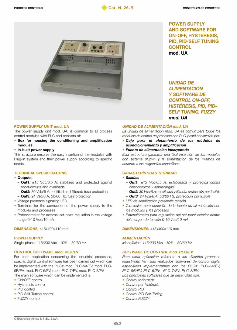
B5.2© Elettronica Veneta & IN.EL. S.p.A.
Cat. N. 26-B
UNIDAD DEALIMENTACIÓNY SOFTWARE DECONTROL ON-OFF,HISTÉRESIS, PID, PID-SELF TUNING, FUZZYmod. UA
POWER SUPPLYAND SOFTWARE FORON-OFF, HYSTERESIS,PID, PID-SELF TUNINGCONTROLmod. UA
POWER SUPPLY UNIT mod. UA The power supply unit mod. UA, is common to all processcontrol modules with PLC and consists of: • Box for housing the conditioning and amplification
modules • In-built power supplyThis structure ensures the easy insertion of the modules withPlug-In system and their power supply according to specificneeds.
TECHNICAL SPECIFICATIONS• Outputs:
– Out1: ±15 Vdc/0.5 A; stabilized and protected againstshort-circuits and overloads
– Out2: 30 Vdc/6 A; rectified and filtered; fuse protection– Out3: 24 Vac/6 A, 50/60 Hz; fuse protection
• Voltage presence signaling LED • Terminals for the connection of the power supply to the
modules and processes• Potentiometer for external set-point regulation in the voltage
range 0-10 Vdc/10 mA
DIMENSIONS: 415x400x110 mm
POWER SUPPLYSingle-phase: 115/230 Vac ±10% – 50/60 Hz
CONTROL SOFTWARE mod. REG/EVFor each application concerning the industrial processes,specific digital control software has been carried out which canbe implemented with the PLCs: mod. PLC-5A/EV, mod. PLC-5B/EV, mod. PLC-6/EV, mod. PLC-7/EV, mod. PLC-8/EV.The main software which can be implemented is:• ON/OFF control• Hysteresis control• PID control• PID Self-Tuning control• FUZZY control
UNIDAD DE ALIMENTACIÓN mod. UA La unidad de alimentación mod. UA es común para todos losmódulos de control de procesos con PLC y está constituida por:• Caja para el alojamiento de los módulos de
acondicionamiento y amplificación• Fuente de alimentación incorporada Esta estructura garantiza una fácil inserción de los móduloscon sistema plug-in y la alimentación de los mismos deacuerdo a las exigencias específicas.
CARACTERÍSTICAS TÉCNICAS• Salidas:
– Out1: ±15 Vcc/0,5 A; estabilizada y protegida contracortocircuitos y sobrecargas
– Out2: 30 Vcc/6 A; rectificada y filtrada; protección por fusible– Out3: 24 Vca/6 A, 50/60 Hz; protección por fusible
• LED de señalización presencia tensión• Terminales para conexión de la fuente de alimentación con
los módulos y los procesos• Potenciómetro para regulación del set-point exterior dentro
del margen de tensión 0-10 Vcc/10 mA
DIMENSIONES: 415x400x110 mm
ALIMENTACIÓNMonofásica: 115/230 Vca ±10% – 50/60 Hz
SOFTWARE DE CONTROL mod. REG/EVPara cada aplicación referente a los distintos procesosindustriales han sido realizados softwares de control digitalespecíficos implementables con los PLCs: PLC-5A/EV,PLC-5B/EV, PLC-6/EV, PLC-7/EV, PLC-8/EV.Los principales softwares que se desarrollan son:• Control todo/nada• Control por histéresis• Control PID • Control PID Self-Tuning• Control FUZZY
PROCESS CONTROLS CONTROLES DE PROCESOS
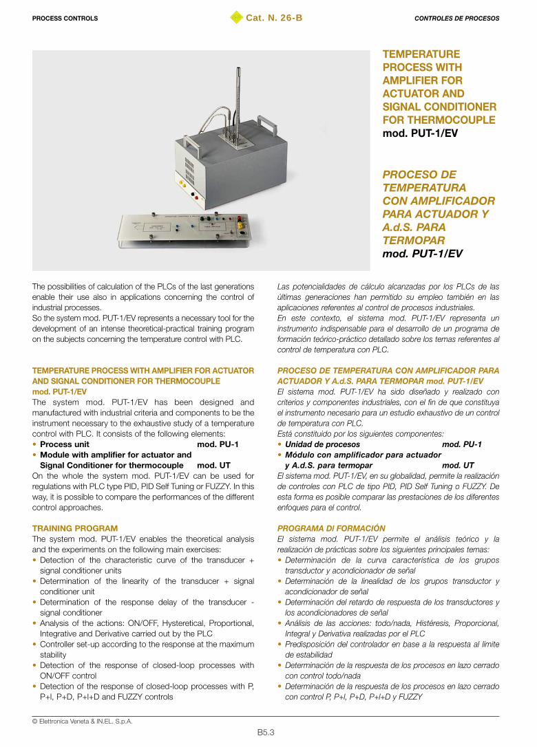
B5.3© Elettronica Veneta & IN.EL. S.p.A.
Cat. N. 26-B
PROCESO DETEMPERATURACON AMPLIFICADORPARA ACTUADOR YA.d.S. PARATERMOPARmod. PUT-1/EV
TEMPERATUREPROCESS WITHAMPLIFIER FORACTUATOR ANDSIGNAL CONDITIONERFOR THERMOCOUPLEmod. PUT-1/EV
The possibilities of calculation of the PLCs of the last generationsenable their use also in applications concerning the control ofindustrial processes. So the system mod. PUT-1/EV represents a necessary tool for thedevelopment of an intense theoretical-practical training programon the subjects concerning the temperature control with PLC.
TEMPERATURE PROCESS WITH AMPLIFIER FOR ACTUATORAND SIGNAL CONDITIONER FOR THERMOCOUPLEmod. PUT-1/EVThe system mod. PUT-1/EV has been designed andmanufactured with industrial criteria and components to be theinstrument necessary to the exhaustive study of a temperaturecontrol with PLC. It consists of the following elements:• Process unit mod. PU-1• Module with amplifier for actuator and
Signal Conditioner for thermocouple mod. UTOn the whole the system mod. PUT-1/EV can be used forregulations with PLC type PID, PID Self Tuning or FUZZY. In thisway, it is possible to compare the performances of the differentcontrol approaches.
TRAINING PROGRAMThe system mod. PUT-1/EV enables the theoretical analysisand the experiments on the following main exercises:• Detection of the characteristic curve of the transducer +
signal conditioner units• Determination of the linearity of the transducer + signal
conditioner unit• Determination of the response delay of the transducer -
signal conditioner • Analysis of the actions: ON/OFF, Hysteretical, Proportional,
Integrative and Derivative carried out by the PLC• Controller set-up according to the response at the maximum
stability • Detection of the response of closed-loop processes with
ON/OFF control• Detection of the response of closed-loop processes with P,
P+l, P+D, P+l+D and FUZZY controls
Las potencialidades de cálculo alcanzadas por los PLCs de lasúltimas generaciones han permitido su empleo también en lasaplicaciones referentes al control de procesos industriales.En este contexto, el sistema mod. PUT-1/EV representa uninstrumento indispensable para el desarrollo de un programa deformación teórico-práctico detallado sobre los temas referentes alcontrol de temperatura con PLC.
PROCESO DE TEMPERATURA CON AMPLIFICADOR PARAACTUADOR Y A.d.S. PARA TERMOPAR mod. PUT-1/EVEl sistema mod. PUT-1/EV ha sido diseñado y realizado concriterios y componentes industriales, con el fin de que constituyael instrumento necesario para un estudio exhaustivo de un controlde temperatura con PLC.Está constituido por los siguientes componentes:• Unidad de procesos mod. PU-1• Módulo con amplificador para actuador
y A.d.S. para termopar mod. UTEl sistema mod. PUT-1/EV, en su globalidad, permite la realizaciónde controles con PLC de tipo PID, PID Self Tuning o FUZZY. Deesta forma es posible comparar las prestaciones de los diferentesenfoques para el control.
PROGRAMA Dl FORMACIÓNEl sistema mod. PUT-1/EV permite el análisis teórico y larealización de prácticas sobre los siguientes principales temas:• Determinación de la curva característica de los grupos
transductor y acondicionador de señal• Determinación de la linealidad de los grupos transductor y
acondicionador de señal• Determinación del retardo de respuesta de los transductores y
los acondicionadores de señal• Análisis de las acciones: todo/nada, Histéresis, Proporcional,
Integral y Derivativa realizadas por el PLC• Predisposición del controlador en base a la respuesta al límite
de estabilidad • Determinación de la respuesta de los procesos en lazo cerrado
con control todo/nada• Determinación de la respuesta de los procesos en lazo cerrado
con control P, P+l, P+D, P+l+D y FUZZY
PROCESS CONTROLS CONTROLES DE PROCESOS

• Determinación del error en régimen permanente de losprocesos, de acuerdo al tipo de control utilizado
• Determinación del comportamiento en régimen transitorio de losprocesos, en relación a las constantes de tiempo del programade control.
CARACTERÍSTICAS TÉCNICASUnidad de procesos mod. PU-1La unidad de procesos está constituida por:• Contenedor sólido metálico con camisa termoaislante• Componentes resistivos calefactores• Transductor de temperatura con termopar• Ventilador de refrigeración• Termómetro de mercurio para lectura del valor de la temperatura• Plancha en aluminio, donde se cumple el proceso• 2 terminales para el mando de las resistencias de caldeo por
parte del módulo mod. UT• 2 terminales para el mando del ventilador por parte del módulo
mod. UT• Asideros laterales incorporables para facilitar el transporte en el
laboratorioDIMENSIONES: 386x372x330 mm
Módulo mod. UTEl módulo mod. UT se introduce en la unidad mod. UA, de la cualrecibe la alimentación:• Esquema sinóptico de los circuitos electrónicos presentes• Margen de temperatura: Tamb-250 °C• Margen de salida en tensión: 0..10 V• Terminales de medida y conexión• Toma para cable DIN con 8 polos, para conexión con la unidad
mod. PU-2• Cable DIN con 8 polos• Cables de conexión para acondicionador y amplificadorDIMENSIONES: 386x123x40 mm
Alimentación módulo mod. UT±15 Vcc/0,5 A, 24 Vca/4 A. La alimentación del sistema esproporcionada por la unidad mod. UA.
TEXTOS TEÓRICO-PRÁCTICOS• Manual teórico-aplicativo de presentación del equipo• Manual de las aplicaciones con PLC-5A/EV, PLC-5B/EV,
PLC-6/EV, PLC-7/EV, PLC-8/EV
B5.4© Elettronica Veneta & IN.EL. S.p.A.
• Detection of the permanent state error of the processes,according to the used control
• Detection of the transient state behavior of the processesaccording to the time constants of the control program
TECHNICAL SPECIFICATIONSProcess unit mod. PU-1The process unit consists of:• Solid metal envelope with thermo-insulating air space• Heating resistive elements • Thermocouple temperature transducer• Cooling fan • Mercury thermometer for reading the temperature value • Aluminum plate seat of the process • 2 terminals for control of the heating resistors by module UT• 2 terminals for fan control by module UT• Re-entering side handles for easy transport in the laboratoryDIMENSIONS: 386x372x330 mm
Module mod. UTModule mod. UT is inserted into unit mod. UA from which it ispowered• Silk screen panel of the present electrical circuits• Temperature range: Tamb-250° C• Voltage output range: 0..10 V• Measurement and connection terminals • 8-pole DIN socket for connection to unit PU-1• 8-pole DIN socket• Connection cables for conditioner and amplifier DIMENSIONS: 386x123x40 mm
POWER SUPPLY OF MODULE mod. UT±15 Vdc/0.5 A, 24 Vdc/4 A. The system power supply isprovided by unit mod. UA.
THEORETICAL-EXPERIMENTAL HANDBOOKS• Theoretical-application handbook for equipment presentation • Handbook for the applications with mod. PLC-5A/EV,
mod. PLC-5B/EV, mod. PLC-6/EV, mod. PLC-7/EV,mod. PLC-8/EV
PROCESS CONTROLS CONTROLES DE PROCESOS
EXTERNALSET-POINT
SET POINT EXTERNO
PC STATION FOR PLC PROGRAMMING
ESTACION del COMPUTADOR para PROGRAMACION del PLC
SIGNAL CONDITIONERAND POWER AMPLIFIER
CONDICIONADOR DE SEÑAL Y AMPLIFICADOR DE POTENCIA
mod. UT
TEMPERATURE PROCESS UNIT
UNIDAD DE PROCESO DE TEMPERATURA
mod. PU-1
mod. PUT-1/EV
PLC or PID CONTROLLER
DIGITAL CONTROL ALGORITHM
ON-OFF, Hysteresis, PID, PID - Self Tuning, FUZZY...
CONTROL de PLC o PID
ALGORITMO de CONTROL DIGITAL
ON-OFF, Histéresis, PID, PID - Auto Calibrado, FUZZY...
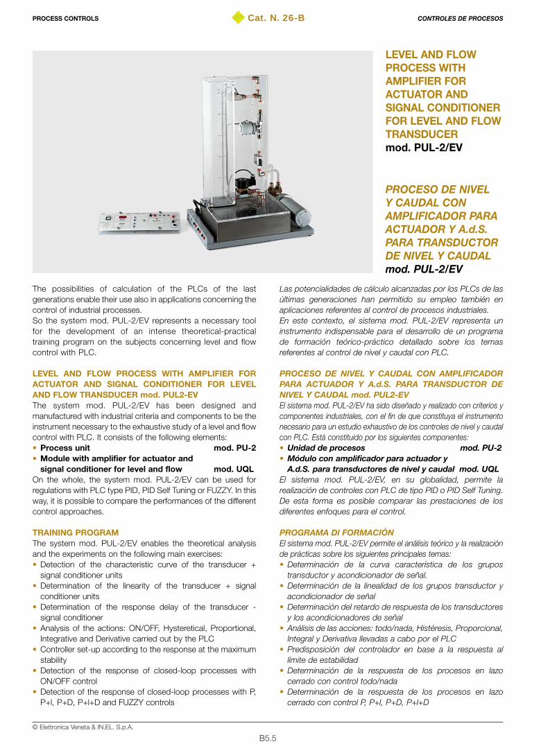
B5.5© Elettronica Veneta & IN.EL. S.p.A.
Cat. N. 26-B
PROCESO DE NIVELY CAUDAL CONAMPLIFICADOR PARAACTUADOR Y A.d.S.PARA TRANSDUCTORDE NIVEL Y CAUDALmod. PUL-2/EV
LEVEL AND FLOWPROCESS WITHAMPLIFIER FORACTUATOR ANDSIGNAL CONDITIONERFOR LEVEL AND FLOWTRANSDUCERmod. PUL-2/EV
The possibilities of calculation of the PLCs of the lastgenerations enable their use also in applications concerning thecontrol of industrial processes. So the system mod. PUL-2/EV represents a necessary toolfor the development of an intense theoretical-practicaltraining program on the subjects concerning level and flowcontrol with PLC.
LEVEL AND FLOW PROCESS WITH AMPLIFIER FORACTUATOR AND SIGNAL CONDITIONER FOR LEVELAND FLOW TRANSDUCER mod. PUL2-EVThe system mod. PUL-2/EV has been designed andmanufactured with industrial criteria and components to be theinstrument necessary to the exhaustive study of a level and flowcontrol with PLC. It consists of the following elements:• Process unit mod. PU-2• Module with amplifier for actuator and
signal conditioner for level and flow mod. UQLOn the whole, the system mod. PUL-2/EV can be used forregulations with PLC type PID, PID Self Tuning or FUZZY. In thisway, it is possible to compare the performances of the differentcontrol approaches.
TRAINING PROGRAMThe system mod. PUL-2/EV enables the theoretical analysisand the experiments on the following main exercises:• Detection of the characteristic curve of the transducer +
signal conditioner units• Determination of the linearity of the transducer + signal
conditioner units• Determination of the response delay of the transducer -
signal conditioner • Analysis of the actions: ON/OFF, Hysteretical, Proportional,
Integrative and Derivative carried out by the PLC• Controller set-up according to the response at the maximum
stability • Detection of the response of closed-loop processes with
ON/OFF control• Detection of the response of closed-loop processes with P,
P+l, P+D, P+l+D and FUZZY controls
Las potencialidades de cálculo alcanzadas por los PLCs de lasúltimas generaciones han permitido su empleo también enaplicaciones referentes al control de procesos industriales.En este contexto, el sistema mod. PUL-2/EV representa uninstrumento indispensable para el desarrollo de un programade formación teórico-práctico detallado sobre los temasreferentes al control de nivel y caudal con PLC.
PROCESO DE NIVEL Y CAUDAL CON AMPLIFICADORPARA ACTUADOR Y A.d.S. PARA TRANSDUCTOR DENIVEL Y CAUDAL mod. PUL2-EVEl sistema mod. PUL-2/EV ha sido diseñado y realizado con criterios ycomponentes industriales, con el fin de que constituya el instrumentonecesario para un estudio exhaustivo de los controles de nivel y caudalcon PLC. Está constituido por los siguientes componentes:• Unidad de procesos mod. PU-2• Módulo con amplificador para actuador y
A.d.S. para transductores de nivel y caudal mod. UQLEl sistema mod. PUL-2/EV, en su globalidad, permite larealización de controles con PLC de tipo PID o PID Self Tuning.De esta forma es posible comparar las prestaciones de losdiferentes enfoques para el control.
PROGRAMA Dl FORMACIÓNEl sistema mod. PUL-2/EV permite el análisis teórico y la realizaciónde prácticas sobre los siguientes principales temas:• Determinación de la curva característica de los grupos
transductor y acondicionador de señal.• Determinación de la linealidad de los grupos transductor y
acondicionador de señal• Determinación del retardo de respuesta de los transductores
y los acondicionadores de señal• Análisis de las acciones: todo/nada, Histéresis, Proporcional,
Integral y Derivativa llevadas a cabo por el PLC• Predisposición del controlador en base a la respuesta al
límite de estabilidad • Determinación de la respuesta de los procesos en lazo
cerrado con control todo/nada• Determinación de la respuesta de los procesos en lazo
cerrado con control P, P+l, P+D, P+l+D
PROCESS CONTROLS CONTROLES DE PROCESOS

B5.6© Elettronica Veneta & IN.EL. S.p.A.
• Detection of the permanent state error of the processes,according to the used control
• Detection of the transient state behavior of the processes,according to the time constants of the control program
TECHNICAL SPECIFICATIONSProcess unit mod. PU-2The process unit consists of:• Metal support • 2 plexiglas tanks: lower and upper (vertical)• Electrical pump• Throttle valve• 1 flow transducer type blade flowmeter • 1 level/pressure transducer type strain gauge• Connection terminals to the unit mod. UQLDIMENSIONS: 420x710x280 mm
POWER SUPPLY OF THE PROCESS UNIT mod. PU-230 Vdc/4 A. Power supply provided by unit mod. UA
Module mod. UQLModule mod. UQL is inserted into unit mod. UA from which itis powered:• Silk screen panel of the present electrical circuits • Level input range: 0-500 mm• Pressure input range: 0–4.9 kPa• Flow input range: 0-4 l/min• Voltage output range: 0..10 V• Measurement and connection terminals • 3-digit display for flow indication• 8-pole DIN socket for connection to unit PUT-2• 8-pole DIN socket• Connection cables for conditioner and amplifier DIMENSIONS: 386x123x40 mm
POWER SUPPLY OF MODULE mod. UQL ±15 Vdc/0.5 A. The system power supply is provided byunit UA.
THEORETICAL-EXPERIMENTAL HANDBOOKS• Theoretical-application handbook for equipment presentation• Handbook for the applications with mod. PLC-5A/EV,
mod. PLC-5B/EV, mod. PLC-6/EV, mod. PLC-7/EV,mod. PLC-8/EV
• Determinación del error en régimen permanente de losprocesos, de acuerdo al tipo de control utilizado
• Determinación del comportamiento en régimen transitorio delos procesos, en relación a las constantes de tiempo delprograma de control
CARACTERÍSTICAS TÉCNICASUnidad de procesos mod. PU-2La unidad de procesos está constituida por:• Soporte metálico• 2 depósitos en plexiglás: inferior y superior (vertical)• Bomba eléctrica• Estrangulador• Transductor de caudal de tipo caudalímetro de aspas• Transductor de nivel/presión de tipo galga extensiométrica• Terminales de conexión a la unidad mod. UQLDIMENSIONES: 420x710x280 mm
ALIMENTACIÓN UNIDAD DE PROCESOS mod. PU-230 Vcc/4 A. Alimentación proporcionada por la unidad mod. UA.
Módulo mod. UQLEl módulo mod. UQL se introduce en la unidad mod. UA, de lacual recibe la alimentación:• Esquema sinóptico de los circuitos electrónicos presentes• Margen de entrada de nivel: 0-500 mm• Margen de entrada de presión: 0-4,9 kPa• Margen de entrada de caudal: 0-4 l/min• Margen de salida en tensión: 0..10 V• Terminales de medida y conexión• Display de 3 dígitos para indicación del caudal • Toma para cable DIN con 8 polos, para conexión con la
unidad mod. PU-2• Cable DIN a 8 polos• Cables de conexión acondicionador y amplificadorDIMENSIONES: 386x123x40 mm
ALIMENTACIÓN MÓDULO mod. UQL±15 Vcc/0,5 A. Alimentación proporcionada por la unidadmod. UA.
TEXTOS TEÓRICO-PRÁCTICOS• Manual teórico-aplicativo de presentación del equipo• Manual de las aplicaciones con PLC-5A/EV, PLC-5B/EV,
PLC-6/EV, PLC-7/EV, PLC-8/EV
PROCESS CONTROLS CONTROLES DE PROCESOS
EXTERNALSET-POINT
SET POINT EXTERNO
PC STATION FOR PLC PROGRAMMING
ESTACION del COMPUTADOR para PROGRAMACION del PLC
SIGNAL CONDITIONERAND POWER AMPLIFIER
CONDICIONADOR DE SEÑAL Y AMPLIFICADOR DE POTENCIA
mod. UQL
LEVEL AND FLOW PROCESS UNIT
UNIDAD DE PROCESO DE NIVEL Y CAUDAL
mod. PU-2
mod. PUL-2/EV
PLC or PID CONTROLLER
DIGITAL CONTROL ALGORITHM
ON-OFF, Hysteresis, PID, PID - Self Tuning, FUZZY...
CONTROL de PLC o PID
ALGORITMO de CONTROL DIGITAL
ON-OFF, Histéresis, PID, PID - Auto Calibrado, FUZZY...
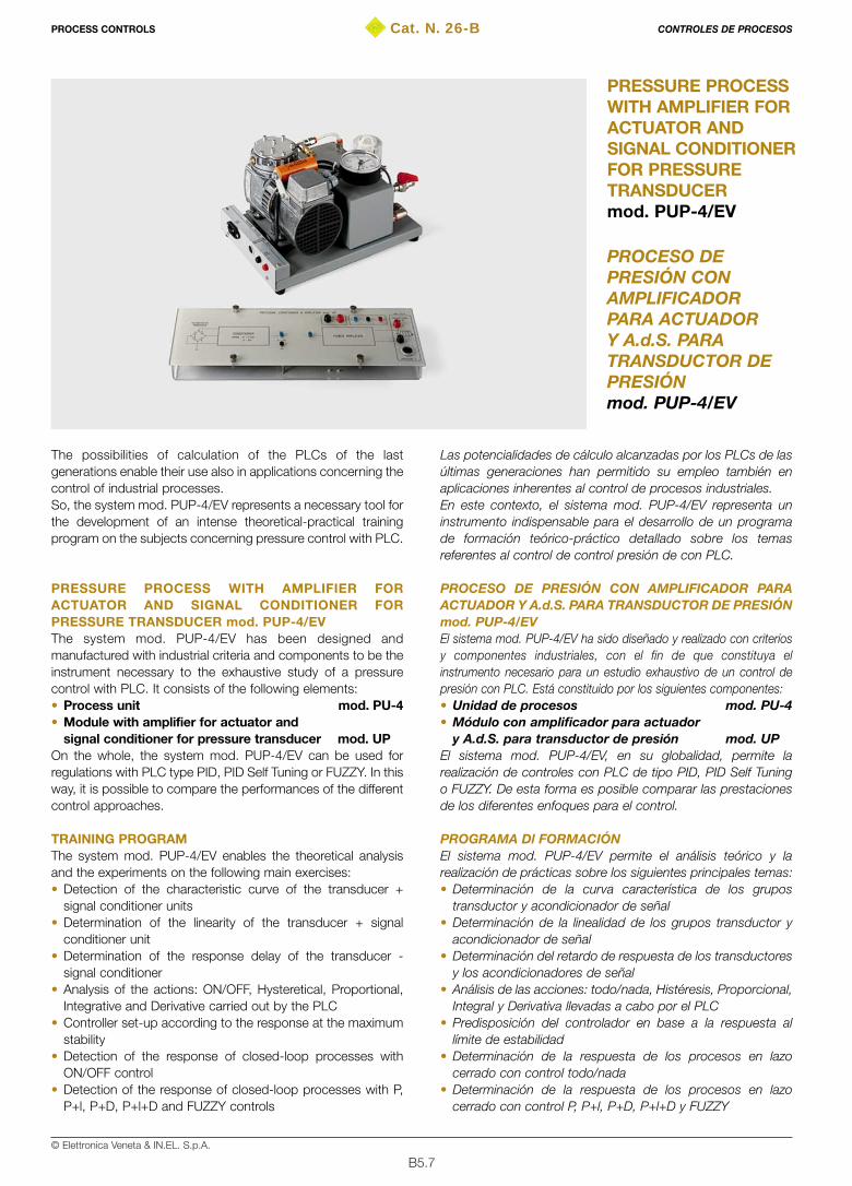
B5.7© Elettronica Veneta & IN.EL. S.p.A.
Cat. N. 26-B
PROCESO DEPRESIÓN CONAMPLIFICADORPARA ACTUADORY A.d.S. PARATRANSDUCTOR DEPRESIÓNmod. PUP-4/EV
PRESSURE PROCESSWITH AMPLIFIER FORACTUATOR ANDSIGNAL CONDITIONERFOR PRESSURETRANSDUCERmod. PUP-4/EV
The possibilities of calculation of the PLCs of the lastgenerations enable their use also in applications concerning thecontrol of industrial processes. So, the system mod. PUP-4/EV represents a necessary tool forthe development of an intense theoretical-practical trainingprogram on the subjects concerning pressure control with PLC.
PRESSURE PROCESS WITH AMPLIFIER FORACTUATOR AND SIGNAL CONDITIONER FORPRESSURE TRANSDUCER mod. PUP-4/EVThe system mod. PUP-4/EV has been designed andmanufactured with industrial criteria and components to be theinstrument necessary to the exhaustive study of a pressurecontrol with PLC. It consists of the following elements:• Process unit mod. PU-4• Module with amplifier for actuator and
signal conditioner for pressure transducer mod. UPOn the whole, the system mod. PUP-4/EV can be used forregulations with PLC type PID, PID Self Tuning or FUZZY. In thisway, it is possible to compare the performances of the differentcontrol approaches.
TRAINING PROGRAMThe system mod. PUP-4/EV enables the theoretical analysisand the experiments on the following main exercises:• Detection of the characteristic curve of the transducer +
signal conditioner units• Determination of the linearity of the transducer + signal
conditioner unit• Determination of the response delay of the transducer -
signal conditioner • Analysis of the actions: ON/OFF, Hysteretical, Proportional,
Integrative and Derivative carried out by the PLC• Controller set-up according to the response at the maximum
stability • Detection of the response of closed-loop processes with
ON/OFF control• Detection of the response of closed-loop processes with P,
P+l, P+D, P+l+D and FUZZY controls
Las potencialidades de cálculo alcanzadas por los PLCs de lasúltimas generaciones han permitido su empleo también enaplicaciones inherentes al control de procesos industriales.En este contexto, el sistema mod. PUP-4/EV representa uninstrumento indispensable para el desarrollo de un programade formación teórico-práctico detallado sobre los temasreferentes al control de control presión de con PLC.
PROCESO DE PRESIÓN CON AMPLIFICADOR PARAACTUADOR Y A.d.S. PARA TRANSDUCTOR DE PRESIÓNmod. PUP-4/EVEl sistema mod. PUP-4/EV ha sido diseñado y realizado con criteriosy componentes industriales, con el fin de que constituya elinstrumento necesario para un estudio exhaustivo de un control depresión con PLC. Está constituido por los siguientes componentes:• Unidad de procesos mod. PU-4• Módulo con amplificador para actuador
y A.d.S. para transductor de presión mod. UPEl sistema mod. PUP-4/EV, en su globalidad, permite larealización de controles con PLC de tipo PID, PID Self Tuningo FUZZY. De esta forma es posible comparar las prestacionesde los diferentes enfoques para el control.
PROGRAMA Dl FORMACIÓNEl sistema mod. PUP-4/EV permite el análisis teórico y larealización de prácticas sobre los siguientes principales temas:• Determinación de la curva característica de los grupos
transductor y acondicionador de señal• Determinación de la linealidad de los grupos transductor y
acondicionador de señal• Determinación del retardo de respuesta de los transductores
y los acondicionadores de señal• Análisis de las acciones: todo/nada, Histéresis, Proporcional,
Integral y Derivativa llevadas a cabo por el PLC• Predisposición del controlador en base a la respuesta al
límite de estabilidad• Determinación de la respuesta de los procesos en lazo
cerrado con control todo/nada• Determinación de la respuesta de los procesos en lazo
cerrado con control P, P+l, P+D, P+l+D y FUZZY
PROCESS CONTROLS CONTROLES DE PROCESOS
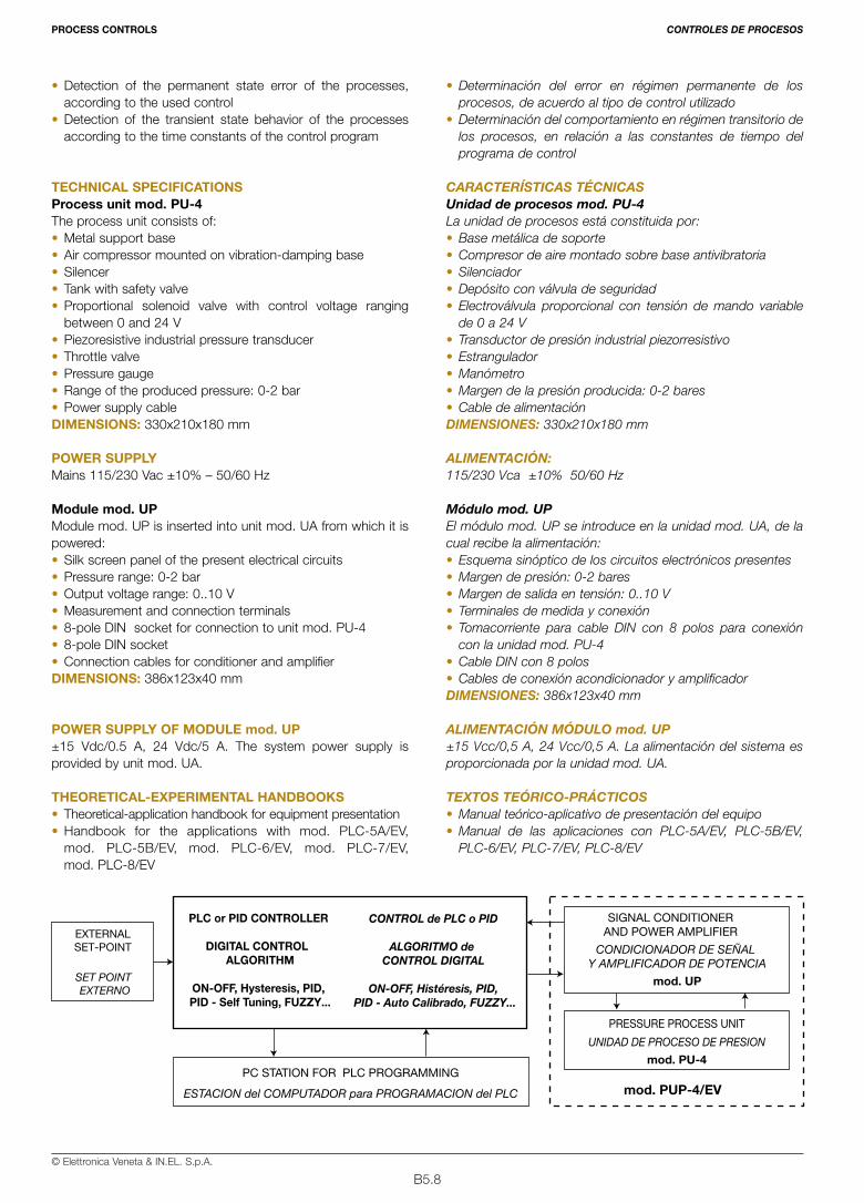
B5.8© Elettronica Veneta & IN.EL. S.p.A.
• Detection of the permanent state error of the processes,according to the used control
• Detection of the transient state behavior of the processesaccording to the time constants of the control program
TECHNICAL SPECIFICATIONSProcess unit mod. PU-4 The process unit consists of: • Metal support base • Air compressor mounted on vibration-damping base• Silencer• Tank with safety valve • Proportional solenoid valve with control voltage ranging
between 0 and 24 V • Piezoresistive industrial pressure transducer • Throttle valve• Pressure gauge • Range of the produced pressure: 0-2 bar• Power supply cable DIMENSIONS: 330x210x180 mm
POWER SUPPLYMains 115/230 Vac ±10% – 50/60 Hz
Module mod. UPModule mod. UP is inserted into unit mod. UA from which it ispowered: • Silk screen panel of the present electrical circuits • Pressure range: 0-2 bar• Output voltage range: 0..10 V• Measurement and connection terminals • 8-pole DIN socket for connection to unit mod. PU-4• 8-pole DIN socket• Connection cables for conditioner and amplifier DIMENSIONS: 386x123x40 mm
POWER SUPPLY OF MODULE mod. UP±15 Vdc/0.5 A, 24 Vdc/5 A. The system power supply isprovided by unit mod. UA.
THEORETICAL-EXPERIMENTAL HANDBOOKS • Theoretical-application handbook for equipment presentation • Handbook for the applications with mod. PLC-5A/EV,
mod. PLC-5B/EV, mod. PLC-6/EV, mod. PLC-7/EV,mod. PLC-8/EV
• Determinación del error en régimen permanente de losprocesos, de acuerdo al tipo de control utilizado
• Determinación del comportamiento en régimen transitorio delos procesos, en relación a las constantes de tiempo delprograma de control
CARACTERÍSTICAS TÉCNICASUnidad de procesos mod. PU-4La unidad de procesos está constituida por:• Base metálica de soporte• Compresor de aire montado sobre base antivibratoria• Silenciador• Depósito con válvula de seguridad• Electroválvula proporcional con tensión de mando variable
de 0 a 24 V • Transductor de presión industrial piezorresistivo• Estrangulador• Manómetro• Margen de la presión producida: 0-2 bares• Cable de alimentación DIMENSIONES: 330x210x180 mm
ALIMENTACIÓN:115/230 Vca ±10% 50/60 Hz
Módulo mod. UPEl módulo mod. UP se introduce en la unidad mod. UA, de lacual recibe la alimentación:• Esquema sinóptico de los circuitos electrónicos presentes • Margen de presión: 0-2 bares• Margen de salida en tensión: 0..10 V• Terminales de medida y conexión • Tomacorriente para cable DIN con 8 polos para conexión
con la unidad mod. PU-4• Cable DIN con 8 polos• Cables de conexión acondicionador y amplificadorDIMENSIONES: 386x123x40 mm
ALIMENTACIÓN MÓDULO mod. UP±15 Vcc/0,5 A, 24 Vcc/0,5 A. La alimentación del sistema esproporcionada por la unidad mod. UA.
TEXTOS TEÓRICO-PRÁCTICOS• Manual teórico-aplicativo de presentación del equipo• Manual de las aplicaciones con PLC-5A/EV, PLC-5B/EV,
PLC-6/EV, PLC-7/EV, PLC-8/EV
PROCESS CONTROLS CONTROLES DE PROCESOS
EXTERNALSET-POINT
SET POINT EXTERNO
PC STATION FOR PLC PROGRAMMING
ESTACION del COMPUTADOR para PROGRAMACION del PLC
SIGNAL CONDITIONERAND POWER AMPLIFIER
CONDICIONADOR DE SEÑAL Y AMPLIFICADOR DE POTENCIA
mod. UP
PRESSURE PROCESS UNIT
UNIDAD DE PROCESO DE PRESION
mod. PU-4
mod. PUP-4/EV
PLC or PID CONTROLLER
DIGITAL CONTROL ALGORITHM
ON-OFF, Hysteresis, PID, PID - Self Tuning, FUZZY...
CONTROL de PLC o PID
ALGORITMO de CONTROL DIGITAL
ON-OFF, Histéresis, PID, PID - Auto Calibrado, FUZZY...

B5.9© Elettronica Veneta & IN.EL. S.p.A.
Cat. N. 26-B
PROCESO DEVELOCIDAD ANGULARCON AMPLIFICADORPARA ACTUADORY A.d.S. PARATACOGENERADORmod. PUV-6/EV
ANGULAR SPEEDPROCESS WITHAMPLIFIER FORACTUATOR AND SIGNALCONDITIONER FORTACHOGENERATORmod. PUV-6/EV
The possibilities of calculation of the PLCs of the lastgenerations enable their use also in applications concerning thecontrol of industrial processes. So, the system mod. PUV-6/EV represents a necessary tool forthe development of an intense theoretical-practical trainingprogram on the subjects concerning angular speed control of aDC motor with PLC.
ANGULAR SPEED PROCESS WITH AMPLIFIER FORACTUATOR AND SIGNAL CONDITIONER FORTACHOGENERATOR mod. PUV-6/EVThe system mod. PUV-6/EV has been designed andmanufactured with industrial criteria and components to be theinstrument necessary to the exhaustive study of an angularspeed control of DC motor with PLC. It consists of the followingelements:• Process unit mod. PU-6• Module with amplifier for actuator and
signal conditioner for tachogenerator mod. UVOn the whole, the system mod. PUV-6/EV can be used forregulations with PLC type PID, PID Self Tuning. In this way, it ispossible to compare the performances of the different controlapproaches.
TRAINING PROGRAMThe system mod. PUV-6/EV enables the theoretical analysisand the experiments on the following main exercises:• Detection of the characteristic curve of the transducer +
signal conditioner units• Determination of the linearity of the transducer + signal
conditioner units• Determination of the response delay of the transducer -
signal conditioner • Analysis of the actions: ON/OFF, Hysteretical, Proportional,
Integrative and Derivative carried out by the PLC• Controller set-up according to the response at the maximum
stability • Response detection of closed-loop processes with ON/OFF
control
Las potencialidades de cálculo alcanzadas por los PLCs de lasúltimas generaciones han permitido su empleo también enaplicaciones inherentes al control de procesos industriales.En este contexto, el sistema mod. PUV-6 representa uninstrumento indispensable para el desarrollo de un programa deformación teórico-práctico detallado sobre los temas referentesal control de la velocidad angular de un motor de c.c. con PLC.
PROCESO DE VELOCIDAD ANGULAR CONAMPLIFICADOR PARA ACTUADOR Y A.d.S. PARATACOGENERADOR mod. PUV-6/EVEl sistema mod. PUV-6/EV ha sido diseñado y realizado concriterios y componentes industriales, con el fin de que constituyael instrumento necesario para un estudio exhaustivo de uncontrol de velocidad angular de un motor de c.c. con PLC.Está constituido por los siguientes componentes:• Unidad de procesos mod. PU-6• Módulo con amplificador para actuador
y A.d.S. para tacogenerador mod. UVEl sistema mod. PUV-6/EV, en su globalidad, permite larealización de controles con PLC de tipo PID o PID Self Tuning.De esta forma es posible comparar las prestaciones de losdiferentes enfoques para el control.
PROGRAMA Dl FORMACIÓNEl sistema mod. PUV-6/EV permite el análisis teórico y larealización de prácticas sobre los siguientes principales temas:• Determinación de la curva característica de los grupos
transductor y acondicionador de señal• Determinación de la linealidad de los grupos transductor y
acondicionador de señal• Determinación del retardo de respuesta de los transductores
y los acondicionadores de señal• Análisis de las acciones: todo/nada, Histéresis, Proporcional,
Integral y Derivativa llevadas a cabo por el PLC• Predisposición del controlador en base a la respuesta al
límite de estabilidad• Determinación de la respuesta de los procesos en lazo
cerrado con control todo/nada
PROCESS CONTROLS CONTROLES DE PROCESOS

B5.10© Elettronica Veneta & IN.EL. S.p.A.
• Response detection of closed-loop processes with P, P+l,P+D, P+l+D and FUZZY controls
• Permanent state error detection of the processes, accordingto the used control
• Transient state behavior detection of the processes accordingto the time constants of the control program
TECHNICAL SPECIFICATIONSProcess unit mod. PU-6The process unit consists of: • Metal support base• Permanent magnets DC motor • Tachogenerator splined to the motor shaft • Transmission optoelectronic sensor • Transparent and opaque disk for optoelectronic transducer• Manual braking device • Rotation speed: 0…3500 RPM• Nominal voltage: 24 V• Nominal power: 50 WDIMENSIONS: 330x120x120 mm
Module mod. UVModule mod. UV is inserted into unit mod. UA from which it ispowered:• Silk screen panel of the present electrical circuits• Speed range: 0-3500 RPM • Voltage output range: 0.10 V• 4-digit display for rotation speed • Measurement and connection terminals • 8-pole DIN socket for connection to unit PU-6• 8-pole DIN socket• Connection cables for conditioner and amplifier DIMENSIONS: 386x123x40 mm
POWER SUPPLY OF MODULE mod. UV±15 Vdc/0.5 A, 30 Vdc/2 A. The system power supply isprovided by unit mod. UA.
THEORETICAL-EXPERIMENTAL HANDBOOKS • Theoretical-application handbook for equipment presentation• Handbook for the applications with mod. PLC-5A/EV,
mod. PLC-5B/EV, mod. PLC-6/EV, mod. PLC-7/EV,mod. PLC-8/EV
• Determinación de la respuesta de los procesos en lazocerrado con control P, P+l, P+D, P+l+D
• Determinación del error en régimen permanente de losprocesos, de acuerdo al tipo de control utilizado
• Determinación del comportamiento en régimen transitorio delos procesos, en relación a las constantes de tiempo delprograma de control
CARACTERÍSTICAS TÉCNICASUnidad de procesos mod. PU-6La unidad de procesos está constituida por:• Base metálica de soporte• Motor de c.c. de imán permanente• Tacogenerador ensamblado en el eje del motor• Sensor optoelelectrónico de transmisión• Disco de trechos transparentes y opacos para transductor
optoelectrónico• Dispositivo de frenada manual• Velocidad de rotación: 0…3.500 r.p.m.• Tensión nominal: 24 V• Potencia nominal: 50 WDIMENSIONES: 330x120x120 mm
Módulo mod. UVEl módulo mod. UV se introduce en la unidad mod. UA, de lacual recibe la alimentación:• Esquema sinóptico de los circuitos electrónicos presentes• Margen de velocidad: 0-3.500 r.p.m.• Margen de salida en tensión: 0..10 V• Display de 4 dígitos para visualización de la velocidad de rotación• Terminales de medida y conexión • Tomacorriente para cable DIN con 8 polos, para conexión
con la unidad mod. PU-6• Cable DIN con 8 polos• Cables de conexión acondicionador y amplificadorDIMENSIONES: 386x123x40 mm
ALIMENTACIÓN MÓDULO mod. UV±15 Vcc/0,5 A, 30 Vcc/2 A. La alimentación del sistema esproporcionada por la unidad mod. UA.
TEXTOS TEÓRICO-PRÁCTICOSS TEÓRICOÁCTICOS• Manual teórico-aplicativo de presentación del equipo• Manual de las aplicaciones con los PLCs: PLC-5A/EV,
PLC-5B/EV, PLC-6/EV, PLC-7/EV, PLC-8/EV
PROCESS CONTROLS CONTROLES DE PROCESOS
EXTERNALSET-POINT
SET POINT EXTERNO
PC STATION FOR PLC PROGRAMMING
ESTACION del COMPUTADOR para PROGRAMACION del PLC
SIGNAL CONDITIONERAND POWER AMPLIFIER
CONDICIONADOR DE SEÑAL Y AMPLIFICADOR DE POTENCIA
mod. UV
SPEED PROCESS UNIT
UNIDAD DE PROCESO DE VELOCIDAD
mod. PU-6
mod. PUP-6/EV
PLC or PID CONTROLLER
DIGITAL CONTROL ALGORITHM
ON-OFF, Hysteresis, PID, PID - Self Tuning, FUZZY...
CONTROL de PLC o PID
ALGORITMO de CONTROL DIGITAL
ON-OFF, Histéresis, PID, PID - Auto Calibrado, FUZZY...

B5.11© Elettronica Veneta & IN.EL. S.p.A.
Cat. N. 26-B
CONTROLADORDIGITAL PIDPARA CONTROLDE PROCESOSmod. PID-S/EV
PID DIGITALREGULATOR FORPROCESS CONTROLmod. PID-S/EV
As the PID regulators of the last generation, the PID digitalregulator for process control mod. PID-S/EV has a structurebased on a high performances microcontroller, analog anddigital inputs and outputs; it can program the regulationfunctions and has a serial interface for communication with thePersonal Computers. The programming of the main parametersof process control is carried out locally from the keyboardpresent on the control unit.The regulator can immediately be used for the control of thedifferent processes suggested in the modules of the StudentTrainer as it is provided with all signal conditioners necessary tothe interfacing to them. Besides, it is provided with a serialinterface for the connection to a Personal Computer for dataacquisition / programming / diagnostics.The main function of the regulator is to control and monitor theprocess continuously according to the programmed regulationalgorithm. The regulator controls 4 regulation loops with “auto-tuning” functions.The programming of the characteristic parameters for Pproportional, D derivative and I integrative regulation is madefrom the keyboard present on the unit or via the parametrizationsoftware provided with the equipment mod. PID-S/EV. A high resolution graphic display provides the numerical orgraphical display of the variables behavior during the regulation(SET POINT, REGULATED VARIABLE, ERROR… ).
TRAINING PROGRAMThe equipment includes many teaching applications on thefollowing main exercises:• Analysis of the structure of a digital process regulator• Programming the regulator functions • Analysis of the regulation parameters such as: proportional,
derivative and integrative coefficient • Connection of the regulator to a personal computer, sampling
of analog signals and relations with the process regulation• Algorithms applied to the functional programming of a digital
process control• Applications with the modules of the Student Trainer:• Process control:
– Temperature process mod. PUT-1/EV– Pressure process mod. PUP-4/EV– Flow and level process mod. PUL-2/EV
Al igual que los controladores PID de generación actual, elcontrolador digital PID para control de procesos mod. PID-S/EVpresenta una estructura basada en un microcontrolador deelevadas prestaciones, entradas y salidas analógicas y digitales,programación de las funciones de regulación e interfaz serie para lacomunicación con ordenadores personales. La programación delos parámetros fundamentales del control de procesos se realizalocalmente mediante el teclado presente en la unidad de control.El controlador puede aplicarse inmediatamente al control de losdiferentes procesos (Proceso de temperatura mod. PUT-1/EV,Proceso de presión mod. PUP-4/EV y Proceso de caudal y nivelmod. PUL-2/EV), ya que está provisto de todos losacondicionadores de señales necesarios para el interfaz con losmismos. Igualmente está provisto de un interfaz serie para elconexionado con un ordenador personal para la adquisición dedatos/programación/diagnóstico.La función fundamental del controlador es la de controlar ymonitorizar continuamente el proceso en base al algoritmo deregulación programado. El controlador gobierna 4 loops deregulación con funciones de “auto-tuning”.La programación de los parámetros característicos de regulación Pproporcional, D derivada e I integral se realiza por medio del tecladopresente en la unidad o a través del software de parametrización endotación con el Entrenador mod. PID-S/EV. Un display gráfico de elevada resolución proporciona la visualizaciónnumérica o gráfica de la marcha de las variables durante laregulación (SET POINT, MAGNITUD REGULADA, ERROR … ).
PROGRAMA DE FORMACIÓNEl equipo contempla una múltiple variedad de aplicacionesdidácticas que cubren los siguientes temas:• Análisis de la estructura de un controlador de procesos digital• Programación de las funciones del controlador• Análisis de los parámetros de regulación: coeficiente
proporcional, derivativo e integral• Conexionado del controlador con un ordenador personal,
muestreo de señales analógicas y relaciones con el control deprocesos
• Algoritmos aplicados en la programación funcional de un controlde procesos digital
• Control de procesos:– Proceso de temperatura mod. PUT-1/EV– Proceso de presión mod. PUP-4/EV– Proceso de caudal y nivel mod. PUL-2/EV
PROCESS CONTROLS CONTROLES DE PROCESOS
B5.12© Elettronica Veneta & IN.EL. S.p.A.
TECHNICAL SPECIFICATIONSMicrocontroller PID regulation section• The main regulation algorithm can be with PID, PI, PD, P or
ON-OFF action (auxiliary output)• PID with 2 degrees of freedom for separate optimization of the
response to the process and set-point variations• Control of 4 simultaneous regulation loops• Included feed-forward regulation function• Included auto-tuning functions• 12 resident control strategies • Gain scheduling
Analog inputs• 4 analog inputs with voltage/current selection possibility• Voltage range: 0..5 V; 0..10 V • Current range: 4..20 mA• Accuracy: 0.1% 16-bit resolution
Digital inputs• 8 optoinsulated auxiliary inputs (0-24 Vdc)
Set Point• Local setting with keys present on the unit • Remote set point in voltage/current
Analog inputs• 4 continuous inputs selectable in voltage/current• Voltage range: 0..5 V; 0..10 V • Current range: 4..20 mA• Resolution: 13 bit
Digital inputs• 8 insulated auxiliary inputs (0-24 Vdc); solid state relay
Signal adapters• 2 voltage adapters: 0..+8V/0..+10V• 2 voltage adapters: -8V..+8V/0..+10V• 2 voltage adapters: 0..+10V/0..+8V• 2 voltage adapters: 0..+10V/-8V..+8V
Serial communication• 1 RS-232 parametrization interface • 1 RS-232 interface for supervision/ parametrization functions• Serial cable for parametrization of the controller from PC
Programming keyboard and graphic display• Very high definition LCD display • Organization with page menu • Real-time display of the regulated variables • Bargraph, trends, alarms control• Possibility of protection password insertion DIMENSIONS: 313x290x355 mm
POWER SUPPLY115/230 Vac ±10%, 50/60Hz
REQUIRED INSTRUMENTS• Oscilloscope• Multimeter
SOFTWAREProcess supervision software mod. SV-1/EV (optional)Powerful software with graphic pages enabling to carry outprocess supervision functions from a PC station connectedto PLC.
THEORETICAL-EXPERIMENTAL HANDBOOKS• Theoretical-application handbook of the equipment with
guide to the process control applications • Installation, use and maintenance handbook
CARACTERÍSTICAS TÉCNICASSección de control PID por microcontrolador• El algoritmo de regulación principal puede ser de acción PID, PI,
PD, P u ON-OFF (salida auxiliar)• PID con 2 grados de libertad para optimizar de forma separada
la respuesta a las variaciones de proceso y el set-point• Gestión de 4 loops de regulación simultáneos• Función de regulación feed-forward incluida• Incluidas funciones de auto-tuning • 12 estrategias de control residentes• Ganancia programable (Gain scheduling)
Entradas analógicas• 4 entradas analógicas seleccionables en tensión/corriente• Margen de tensión: 0..5 V; 0..10 V • Margen de corriente: 4..20 mA• Precisión: 0,1% resolución de 16 bits
Entradas digitales• 8 entradas auxiliares optoaisladas (0-24 Vcc)
Set Point• Predisposición local mediante teclas presentes en la unidad• Set-point remoto en tensión/corriente
Salidas analógicas• 4 salidas continuas seleccionables en tensión/corriente • Margen de tensión: 0..5 V; 0..10 V • Margen de corriente: 4..20 mA• Resolución: 13 bits
Salidas digitales• 8 salidas auxiliare aisladas (0-24 Vcc); relé de estado sólido
Adaptadores de señal• 2 adaptadores de tensión 0..+8V/0..+10V• 2 adaptadores de tensión -8V..+8V/0..+10V• 2 adaptadores de tensión 0..+10V/0..+8V• 2 adaptadores de tensión 0..+10V/-8V..+8V
Comunicación serie• 1 interfaz RS-232 de parametrización• 1 interfaz RS-232 para funciones de supervisión/ parametrización• Cable serie para la parametrización del controlador mediante PC
Teclado de programación y display gráfico• Display LCD de altísima definición• Organización con menús de páginas• Visualización real-time de las magnitudes reguladas• Gestión de bargraph, trends, alarmas• Posibilidad de inserción de contraseñas de protecciónDIMENSIONES: 313x290x355 mm
ALIMENTACIÓN115/230 Vca ±10%, 50/60Hz
INSTRUMENTACIÓN REQUERIDA • Osciloscopio• Multímetro
SOFTWARESoftware de supervisión de procesos mod. SV-1/EV (opcional)Potente software de páginas gráficas que permite realizar, desdeuna estación PC conectada al PLC, funciones de supervisión deprocesos.
TEXTOS TEÓRICO-PRÁCTICOS• Manual teórico-aplicativo del equipo con guía para las aplicaciones
de control de procesos• Manual de instalación, utilización y mantenimiento
PROCESS CONTROLS CONTROLES DE PROCESOS
B6.1© Elettronica Veneta & IN.EL. S.p.A.
PAGE
REAL AUTOMATED SYSTEMS B6.1
Automatic system for Cartesianmanipulation and drilling mod. SAMF/EV B6.3
Automatic test and selectionsystem with rotating indexed tablemod. SATS/EV B6.5
Automatic weighting and selectionsystemmod. SAPS/EV B6.7
PÁG.
SISTEMAS AUTOMATIZADOS REALES B6.1
Sistema automático de manipulacióncartesiana y taladrado mod. SAMF/EV B6.3
Sistema automático de prueba y selecciónde piezas con mesa giratoriamod. SATS/EV B6.5
Sistema automático de pesaje y selecciónde piezasmod. SAPS/EV B6.7
Cat. N. 26-BREAL AUTOMATED SYSTEMS SISTEMAS AUTOMATIZADOS REALES
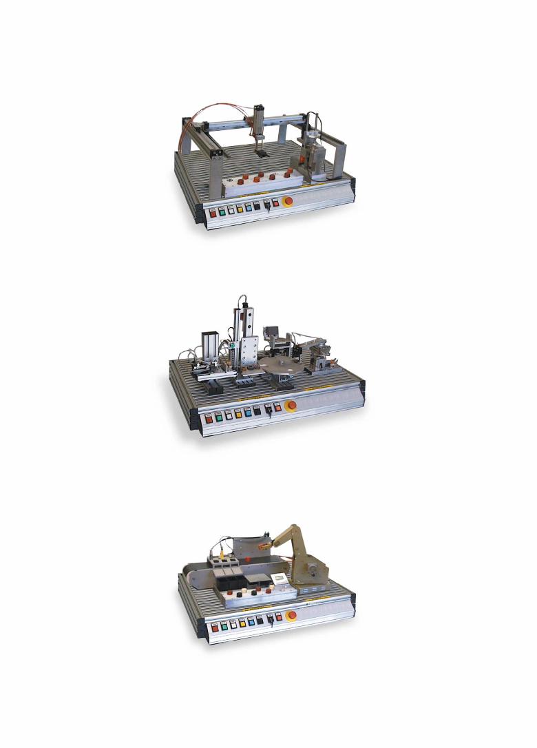
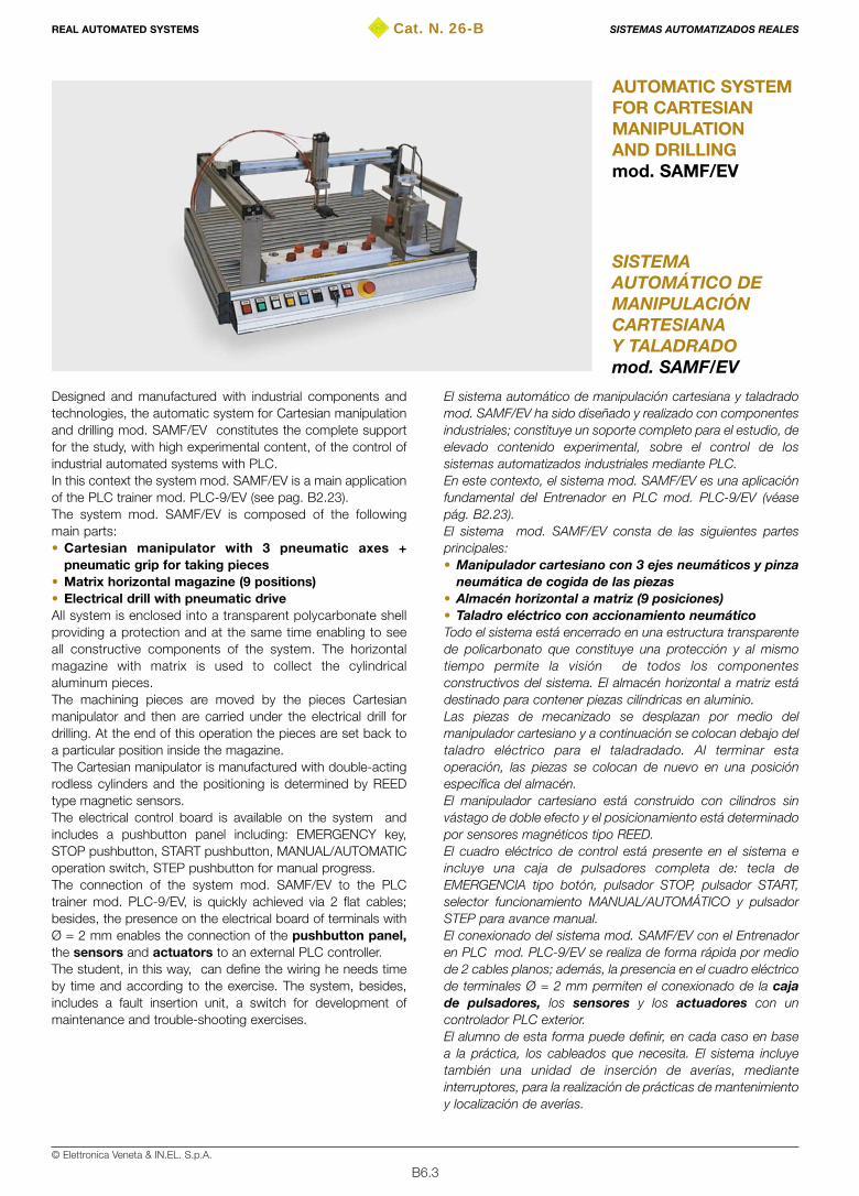
B6.3© Elettronica Veneta & IN.EL. S.p.A.
Cat. N. 26-B
SISTEMAAUTOMÁTICO DEMANIPULACIÓNCARTESIANAY TALADRADOmod. SAMF/EV
AUTOMATIC SYSTEMFOR CARTESIANMANIPULATIONAND DRILLINGmod. SAMF/EV
Designed and manufactured with industrial components andtechnologies, the automatic system for Cartesian manipulationand drilling mod. SAMF/EV constitutes the complete supportfor the study, with high experimental content, of the control ofindustrial automated systems with PLC. In this context the system mod. SAMF/EV is a main applicationof the PLC trainer mod. PLC-9/EV (see pag. B2.23). The system mod. SAMF/EV is composed of the followingmain parts:• Cartesian manipulator with 3 pneumatic axes +
pneumatic grip for taking pieces • Matrix horizontal magazine (9 positions)• Electrical drill with pneumatic driveAll system is enclosed into a transparent polycarbonate shellproviding a protection and at the same time enabling to seeall constructive components of the system. The horizontalmagazine with matrix is used to collect the cylindricalaluminum pieces.The machining pieces are moved by the pieces Cartesianmanipulator and then are carried under the electrical drill fordrilling. At the end of this operation the pieces are set back toa particular position inside the magazine.The Cartesian manipulator is manufactured with double-actingrodless cylinders and the positioning is determined by REEDtype magnetic sensors.The electrical control board is available on the system andincludes a pushbutton panel including: EMERGENCY key,STOP pushbutton, START pushbutton, MANUAL/AUTOMATICoperation switch, STEP pushbutton for manual progress. The connection of the system mod. SAMF/EV to the PLCtrainer mod. PLC-9/EV, is quickly achieved via 2 flat cables;besides, the presence on the electrical board of terminals withØ = 2 mm enables the connection of the pushbutton panel,the sensors and actuators to an external PLC controller. The student, in this way, can define the wiring he needs timeby time and according to the exercise. The system, besides,includes a fault insertion unit, a switch for development ofmaintenance and trouble-shooting exercises.
El sistema automático de manipulación cartesiana y taladradomod. SAMF/EV ha sido diseñado y realizado con componentesindustriales; constituye un soporte completo para el estudio, deelevado contenido experimental, sobre el control de lossistemas automatizados industriales mediante PLC. En este contexto, el sistema mod. SAMF/EV es una aplicaciónfundamental del Entrenador en PLC mod. PLC-9/EV (véasepág. B2.23). El sistema mod. SAMF/EV consta de las siguientes partesprincipales:• Manipulador cartesiano con 3 ejes neumáticos y pinza
neumática de cogida de las piezas• Almacén horizontal a matriz (9 posiciones)• Taladro eléctrico con accionamiento neumáticoTodo el sistema está encerrado en una estructura transparentede policarbonato que constituye una protección y al mismotiempo permite la visión de todos los componentesconstructivos del sistema. El almacén horizontal a matriz estádestinado para contener piezas cilíndricas en aluminio.Las piezas de mecanizado se desplazan por medio delmanipulador cartesiano y a continuación se colocan debajo deltaladro eléctrico para el taladradado. Al terminar estaoperación, las piezas se colocan de nuevo en una posiciónespecífica del almacén.El manipulador cartesiano está construido con cilindros sinvástago de doble efecto y el posicionamiento está determinadopor sensores magnéticos tipo REED.El cuadro eléctrico de control está presente en el sistema eincluye una caja de pulsadores completa de: tecla deEMERGENCIA tipo botón, pulsador STOP, pulsador START,selector funcionamiento MANUAL/AUTOMÁTICO y pulsadorSTEP para avance manual. El conexionado del sistema mod. SAMF/EV con el Entrenadoren PLC mod. PLC-9/EV se realiza de forma rápida por mediode 2 cables planos; además, la presencia en el cuadro eléctricode terminales Ø = 2 mm permiten el conexionado de la cajade pulsadores, los sensores y los actuadores con uncontrolador PLC exterior.El alumno de esta forma puede definir, en cada caso en basea la práctica, los cableados que necesita. El sistema incluyetambién una unidad de inserción de averías, medianteinterruptores, para la realización de prácticas de mantenimientoy localización de averías.
REAL AUTOMATED SYSTEMS SISTEMAS AUTOMATIZADOS REALES

B6.4© Elettronica Veneta & IN.EL. S.p.A.
TRAINING PROGRAMThe system mod. SAMF/EV enables the study of the followingmain subjects:• Principles of pneumatics and electropneumatics • Elements of pneumatic control: solenoid valves• Single and double-acting pneumatic cylinders • Sensors• Cartesian robotics• Automation with PLC• System diagnostics • Driving of automated systems • Trouble-shooting and maintenance of the automatic systems• HMI (Human Machine Interface) technologies• Supervision technologies• Use of industrial user panels• Programming exercises with PLC mod. PLC-9/EV• Exercises with the use of the optional industrial user panel
mod. IOP/EV• Supervision exercises with optional software mod. SVS-1/EV
TECHNICAL SPECIFICATIONS• Polycarbonate transparent protection • Rodless double-acting cylinders • Solenoid valves for pneumatic actuators control: 5/2 ways,
3/2 ways• Pneumatic manipulation grip unit• Cylindrical machining pieces: aluminum• Electrical drilling machine• 9-position (3x3) matrix horizontal position magazine• Sensors: REED, optical fiber, capacitive• Electrical control board with 2 connection interfaces, via flat
cable, to the I/O of the PLC trainer mod. PLC-9/EV; besides,there are 2-mm terminals for PLC connection via cables ofthe same diameter
• Pushbutton board with: EMERGENCY keyboard, STARTpushbutton, STOP pushbutton, MANUAL/AUTOMATICoperation switch, manual progress pushbutton
• 1 40-pin flat cable for analog/digital input connection of thePLC trainer mod. PLC-9/EV
• 1 32-pin flat cable for digital/analog output connection of thePLC trainer mod. PLC-9/EV
• Set of electrical cables Ø = 2 mm for PLC connection to theelectrical board
• Fault insertion unit with switch; 8 insertable faults
DIMENSIONS600x300x600 mm
WEIGHT20 kg
POWER SUPPLY115/230 Vac ±10% – 50/60 Hz
THEORETICAL-EXPERIMENTAL HANDBOOKS • Theory and exercise handbook • Installation, use and maintenance handbook
PROGRAMA DE FORMACIÓNEl sistema mod. SAMF/EV permite el estudio de los siguientesprincipales temas:• Principios de neumática y electroneumática• Elementos de control neumático: electroválvulas• Cilindros neumáticos de simple efecto y doble efecto• Sensores• Robótica cartesiana• Automatización con PLC• Diagnóstico del sistema• Pilotaje de sistemas automatizados• Localización de averías y mantenimiento en los sistemas
automáticos• Tecnologías HMI (Human Machine Interface) • Tecnologías de la supervisión• Utilización de paneles operadores industriales• Prácticas de programación con el PLC mod. PLC-9/EV• Prácticas con utilización del panel operador industrial mod.
IOP/EV (opcional)• Prácticas de supervisión con software mod. SVS-1/EV
(opcional)
CARACTERÍSTICAS TÉCNICAS• Protección transparente en policarbonato• Cilindros de doble efecto sin vástago• Electroválvulas de control de los actuadores neumáticos: 5/2
vías, 3/2 vías• Unidad pinza manipuladora neumática• Piezas de mecanizado cilíndricas en aluminio• Taladro eléctrico • Almacén horizontal con matriz de 9 posiciones (3x3)• Sensores: tipo REED, de fibra óptica, capacitivos• Cuadro eléctrico de control con 2 interfaces de conexionado,
mediante cable plano, a las E/S del Entrenador en PLC mod.PLC-9/EV; igualmente están presentes terminales de 2 mm parael conexionado con el PLC mediante cables del mismo diámetro
• Caja de pulsadores completa de: tecla de EMERGENCIA tipobotón, pulsador de START, pulsador de STOP, selectorfuncionamiento MANUAL/AUTOMÁTICO y pulsador deavance manual
• Cable plano de 40 pins para el conexionado de las entradasdigitales/analógicas del Entrenador en PLC mod. PLC-9/EV
• Cable plano de 32 pins para el conexionado de las salidasdigitales/analógicas del Entrenador en PLC mod. PLC-9/EV
• Juego de cables eléctricos Ø = 2 mm para el conexionadodel PLC al cuadro eléctrico
• Unidad de inserción de averías mediante interruptor; númerode averías insertables igual a 8
DIMENSIONES600x300x600 mm
PESO20 kg
ALIMENTACIÓN115/230 Vca ±10% – 50/60 Hz
TEXTOS TEÓRICO-PRÁCTICOS• Manual de teoría y prácticas• Manual de instalación, utilización y mantenimiento
REAL AUTOMATED SYSTEMS SISTEMAS AUTOMATIZADOS REALES

B6.5© Elettronica Veneta & IN.EL. S.p.A.
Cat. N. 26-B
SISTEMAAUTOMÁTICODE PRUEBA YSELECCIÓN DEPIEZAS CONMESA GIRATORIAmod. SATS/EV
AUTOMATIC TESTAND SELECTIONSYSTEM WITHROTATINGINDEXED TABLEmod. SATS/EV
Designed and manufactured with industrial components andtechnologies, the automatic test and selection system mod.SATS/EV constitutes the complete support for the study, withhigh experimental content, of the control of industrialautomated systems with PLC. In this context the system mod. SATS/EV is a main applicationof the PLC trainer mod. PLC-9/EV (see page B2.23 ). The system mod. SATS/EV is composed of the following mainparts:• 4-position indexed rotating table • Pneumatic cylinder for pieces feeding • Pneumatic manipulator • 3-lane chute All system is enclosed into a transparent polycarbonate shellproviding a protection and at the same time enabling to see allconstructive components of the system. A feeding cylinderpushes the machining pieces on the 4-position indexed table.The indexed table, turning by the action of a DC electricalmotor, takes the pieces to the capacitive, optical, inductivesensors for detecting the kind of material. 3 kinds of materialcan be coded: steel, brass, plastic. Once the material is coded,an electro-pneumatic manipulator, with 3 degrees of freedom,takes the piece and sets it in one of the 3 lanes of the chuteaccording to the kind of material. The indexed table positioning occur via micro-switch. InductiveREED sensors are used for the positioning of the electro-pneumatic manipulator.The electrical control board of the system mod. SATS/EV ispresent on the system and includes a pushbutton panelcomplete of: EMERGENCY pushbutton, STOP pushbutton,START pushbutton, MANUAL/AUTOMATIC operation switch,STEP pushbutton for manual progress. The connection of the system mod. SATS/EV to the PLC trainermod. PLC-9/EV, is quickly achieved via 2 flat cables;furthermore, the presence on the electrical board of terminalswith Ø = 2 mm enables the connection of the pushbuttonpanel, the sensors and actuators to an external PLC controller.The student, in this way, can define the wiring he needs timeby time and according to the exercise. The system, besides,includes a fault insertion unit, a switch for development ofmaintenance and trouble-shooting exercises.
El sistema automático de prueba y selección de piezasmod. SATS/EV ha sido diseñado y realizado con componentes ytecnologías industriales; constituye un soporte completo para elestudio, de elevado contenido experimental, sobre el control delos sistemas automatizados industriales mediante PLC. En este contexto, el sistema mod. SATS/EV es una aplicaciónfundamental del Entrenador en PLC mod. PLC-9/EV (véasepág. B2.23).El sistema mod. SATS/EV consta de las siguientes partes principales:• Mesa giratoria con 4 posiciones• Cilindro neumático de alimentación piezas• Manipulador neumático • Rampa de 3 víasTodo el sistema está encerrado en una estructura transparentede policarbonato que constituye una protección y al mismotiempo permite la visión de todos los componentesconstructivos del sistema.Un cilindro de alimentación envía las piezas de mecanizado haciala mesa giratoria con 4 posiciones. La mesa giratoria giraaccionada mediante un motor eléctrico de CC y sitúa las piezas encorrespondencia con los sensores capacitivo, óptico e inductivopara el reconocimiento del tipo de material. Pueden codificarse 3tipos de material: acero, latón y plástico. Una vez codificado elmaterial, un manipulador electroneumático, con 3 grados delibertad, coge la pieza y la pone en una de las 3 vías de la rampaen base a la tipología del material. El posicionamiento de la mesa giratoria se realiza mediantemicrointerruptor. Sensores inductivos tipo REED se utilizan para elposicionamiento del manipulador electroneumático.El cuadro eléctrico de control del sistema mod. SATS/EV estápresente en el sistema e incluye una caja de pulsadores completade: tecla de EMERGENCIA tipo botón, pulsador STOP, pulsadorSTART, selector funcionamiento MANUAL/AUTOMÁTICO ypulsador STEP para avance manual. El conexionado del sistema mod. SATS/EV con el Entrenador en PLCmod. PLC-9/EV se realiza de forma rápida por medio de 2 cablesplanos; además, la presencia en el cuadro eléctrico de terminalesØ = 2 mm permiten el conexionado de la caja de pulsadores, lossensores y los actuadores a un controlador PLC exterior.El alumno de esta forma puede definir, en cada caso en base a lapráctica, los cableados que necesita. El sistema incluye también unaunidad de inserción de averías, mediante interruptores, para larealización de prácticas de mantenimiento y localización de averías.
REAL AUTOMATED SYSTEMS SISTEMAS AUTOMATIZADOS REALES
B6.6© Elettronica Veneta & IN.EL. S.p.A.
TRAINING PROGRAMThe system mod. SATS/EV enables the study of the followingmain subjects:• Principles of pneumatics and electropneumatics• Elements of pneumatic control: solenoid valves• Simple and double-acting cylinders• Sensors: capacitive, inductive, optical, optical fiber, REED
micro-switch• Automation with PLC• Programming languages: AWL, KOP, FUP• Base and advanced programming of the PLC• System diagnostics• Driving of automated systems • Trouble-shooting and maintenance in automatic systems• HMI technologies (Human Machine Interface) • Supervision technologies • Use of industrial user panels• Programming exercises with PLC mod. PLC-9/EV• Exercises with the use of optional industrial user panel
mod. IOP/EV• Supervision exercises with optional software mod. SVS-1/EV
TECHNICAL SPECIFICATIONS• Transparent polycarbonate protection• Double-acting cylinder for pieces feeding with metal slide • 4-places aluminum indexed table activated by DC electrical
motor • Sensors: capacitive, optical, inductive, micro-switch, REED • Electro-pneumatic manipulator with 3 degrees of freedom
provided with pneumatic grip• Solenoid valves for pneumatic actuators control: 5/2 ways,
3/2 ways• 3–way chute to select the pieces• Electrical control board with 2 connection interfaces, via flat
cable, to the I/O of the PLC trainer mod. PLC-9/EV; there areterminals, beside, with diameter Ø = 2 mm for the PLCconnection via electrical cables
• Pushbutton with: EMERGENCY key, START pushbutton,STOP pushbutton, MANUAL/AUTOMATIC operation switch,manual progress pushbutton
• 1 40-pin flat cable for digital/analog inputs connection of thePLC trainer mod. PLC-9/EV
• 1 32-pin flat cable for digital/analog outputs connection ofPLC trainer mod. PLC-9/EV
• Set of electrical cables Ø = 2 mm for PLC connection toelectrical board
• Set of electrical cables for PLC connection to the electricalboard
• PLC programming cable from PC• Fault insertion unit with switch; 8 insertable faults
DIMENSIONS: 250x200x250 mm
WEIGHT: 10 kg
POWER SUPPLY115/230 Vac ±10% – 50/60 Hz
THEORETICAL-EXPERIMENTAL HANDBOOKS• Theory and exercise handbook • Installation, use and maintenance handbook
PROGRAMA DE FORMACIÓNEl sistema mod. SATS/EV permite el estudio de los siguientesprincipales temas:• Principios de neumática y electroneumática• Elementos de control neumático: electroválvulas• Cilindros neumáticos de simple efecto y doble efecto• Sensores: capacitivos, inductivos, ópticos, de fibra óptica,
REED, microinterruptores• Automatización con PLC• Lenguajes de programación AWL, KOP, FUP• Programación básica y avanzada del PLC• Diagnóstico del sistema• Pilotaje de sistemas automatizados• Localización de averías y mantenimiento en los sistemas
automáticos• Tecnologías HMI (Human Machine Interface) • Tecnologías de la supervisión• Utilización de paneles operadores industriales• Prácticas de programación con el PLC mod. PLC-9/EV• Prácticas con la utilización del panel operador industrial
mod. IOP/EV (opcional)• Prácticas de supervisión con software mod. SVS-1/EV (opcional)
CARACTERÍSTICAS TÉCNICAS• Protección transparente en policarbonato• Cilindro de doble efecto de alimentación de las piezas con
corredera metálica• Mesa giratoria en aluminio con 4 posiciones accionada por
motor eléctrico de CC• Sensores de tipo: capacitivo, óptico, inductivo, micro-
interruptor, REED • Manipulador electroneumático con 3 grados de libertad provisto
de pinza neumática• Electroválvulas de control de los actuadores neumáticos: 5/2
vías, 3/2 vías• Rampa de 3 vías para la selección de las piezas• Cuadro eléctrico de control con 2 interfaces de conexión,
mediante cable plano, a las E/S del Entrenador en PLC mod.PLC-9/EV; igualmente están presentes terminales de 2 mm parael conexionado con el PLC mediante cables del mismo diámetro
• Caja de pulsadores completa de: tecla de EMERGENCIA tipobotón, pulsador de START, pulsador de STOP, selectorfuncionamiento MANUAL/AUTOMÁTICO y pulsador deavance manual
• Cable plano de 40 pins para el conexionado de las entradasdigitales/analógicas del Entrenador en PLC mod. PLC-9/EV
• Cable plano de 32 pins para el conexionado de las salidasdigitales/analógicas del Entrenador en PLC mod. PLC-9/EV
• Juego de cables eléctricos Ø = 2 mm para el conexionado delPLC al cuadro eléctrico
• Cable de programación del PLC mediante el PC• Unidad de inserción averías mediante interruptor; número de
averías insertables igual a 8
DIMENSIONES: 250x200x250 mm
PESO: 10 kg
ALIMENTACIÓN115/230 Vca ±10% – 50/60 Hz
TEXTOS TEÓRICO-PRÁCTICOS• Manual de teoría y prácticas• Manual de instalación, utilización y mantenimiento
REAL AUTOMATED SYSTEMS SISTEMAS AUTOMATIZADOS REALES

B6.7© Elettronica Veneta & IN.EL. S.p.A.
Cat. N. 26-B
SISTEMAAUTOMÁTICODE PESAJE YSELECCIÓNDE PIEZASmod. SAPS/EV
AUTOMATICWEIGHTING ANDSELECTION SYSTEMmod. SAPS/EV
Designed and manufactured with industrial components andtechnologies, the automatic weighting and selection systemmod. SAPS/EV constitutes the complete support for the study,with high experimental content, of the control of industrialautomated system with PLC. In this context the system mod. SAPS/EV is a main applicationof the PLC trainer mod. PLC-9/EV (see page B2.23 ). The system mod. SAPS/EV is composed of the followingmain parts:• Conveyor belt driven by DC motor • Pneumatic manipulator with feeding sucker• Load cell for weighting the machining pieces• 2-lane selection unitAll system is enclosed into a transparent polycarbonate shellproviding a protection and at the same time enabling to see allconstructive components of the system. The aluminum cylindrical machining pieces are pushed along aproper static support by a feeding cylinder. Now, the pneumaticmanipulator with feeding sucker takes the pieces to a load cellfor weight transduction. Once weighted, the pieces are set onthe conveyor belt that conveys them toward the 2-lane selectionunit. If the pieces are not inside a particular weight range theyare rejected to a lane, otherwise pushed to another one. The electrical control board is available on the system andincludes a pushbutton panel including: EMERGENCY key,STOP pushbutton, START pushbutton, MANUAL/AUTOMATICoperation switch, STEP pushbutton for manual progress,potentiometer for setting the weight value.The connection of the system mod. SAPS/EV to the PLCtrainer mod. PLC-9/EV, is quickly achieved via 2 flat cables;furthermore, the presence on the electrical board of terminalswith Ø = 2 mm enables the connection of the pushbuttonpanel, the sensors and actuators to an external PLC controller.The student, in this way, can define the cabling he needs timeby time and according to the exercise. The system, besides,includes a fault insertion unit, a switch for development ofmaintenance and trouble-shooting exercises.
TRAINING PROGRAMThe system mod. SAPS/EV enables the study of the followingmain subjects:• Principles of pneumatics and electropneumatics
El sistema automático de pesaje y selección de piezasmod. SAPS/EV ha sido diseñado y realizado con componentesindustriales y constituye un soporte completo para el estudio, deelevado contenido experimental, sobre el control de los sistemasautomatizados industriales mediante PLC. En este contexto, el sistema mod. SAPS/EV es una aplicaciónfundamental del Entrenador en PLC mod. PLC-9/EV (véase pág.B2.23). El sistema mod. SAPS/EV consta de las siguientes partesprincipales:• Cinta transportadora accionada mediante motor de CC • Manipulador neumático con ventosa• Célula de carga para pesaje de las piezas de mecanizado• Unidad de selección con 2 víasTodo el sistema está encerrado en una estructura transparente depolicarbonato que constituye una protección y al mismo tiempopermite la visión de todos los componentes constructivos del sistema.Las piezas de mecanizado, en aluminio y de forma cilíndrica, semueven hacia un soporte estático por medio de un cilindro dealimentación. A este punto el manipulador neumático con ventosacoloca las piezas en una célula de carga para la conversión delpeso. Una vez pesadas las piezas, se colocan en la cintatransportadora que las acarrea hacia la unidad de selección de 2vías. Si las piezas no cumplen con cierto margen de peso sonapartadas en una vía, de lo contrario se dirigen hacia la otra.El cuadro eléctrico de control está incorporado en el sistema eincluye una caja de pulsadores completa de tecla de EMERGENCIAtipo botón, pulsador STOP, pulsador START, selectorfuncionamiento MANUAL/AUTOMÁTICO, pulsador STEP paraavance manual y potenciómetro para seleccionar el valor de peso.El conexionado del sistema mod. SAPS/EV con el Entrenador en PLCmod. PLC-9/EV se realiza de forma rápida por medio de 2 cablesplanos; además, la presencia en el cuadro eléctrico de terminalesØ = 2 mm permiten el conexionado de la caja de pulsadores, lossensores y los actuadores a un controlador PLC exterior.El alumno de esta forma puede definir, en cada caso en base a lapráctica, los cableados que necesita. El sistema incluye también unaunidad de inserción de averías, mediante interruptores, para larealización de prácticas de mantenimiento y localización de averías.
PROGRAMA DE FORMACIÓNEl sistema mod. SAPS/EV permite el estudio de los siguientesprincipales temas:• Principios de neumática y electroneumática
REAL AUTOMATED SYSTEMS SISTEMAS AUTOMATIZADOS REALES

B6.8© Elettronica Veneta & IN.EL. S.p.A.
• Elements of pneumatic control: solenoid valves• Simple and double-acting cylinders• Sensors: capacitive, inductive, optical and REED • Load cells and signal conditioners • Automation with PLC• System diagnostics• Driving of automated systems • Trouble-shooting and maintenance in automatic systems• HMI technologies (Human Machine Interface) • Supervision technologies • Use of industrial user panels• Programming exercises with PLC mod. PLC-9/EV• Exercises with the use of optional industrial user panel
mod. IOP/EV• Supervision exercises with optional software mod. SVS-1/EV
TECHNICAL SPECIFICATIONS• Transparent polycarbonate protection• Conveyor belt driven by DC motor• Pieces magazine: transparent plexiglass tube• Single-acting cylinder for feeding pieces from magazine • Control solenoid valves for pneumatic actuators: 5/2 ways,
3/2 ways• Cylindrical aluminum pieces of different weight• Load cell for weight transduction of the machining pieces.
Weighting range of 0..600 gr• Signal conditioner for load cell; voltage range: 0..10V • 2 metal lanes for pieces selection• 2 single-acting cylinders for pieces selection• Pneumatic manipulator with feeding sucker • Sensors: REED, inductive, capacitive, optical • Electrical control board with 2 connection interfaces, via flat
cable, to the I/O of the PLC trainer mod. PLC-9/EV; there areterminals, beside, with diameter Ø =2 mm for the PLCconnection via cables with the same diameter
• Pushbutton with: EMERGENCY key, START pushbutton,STOP pushbutton, MANUAL/AUTOMATIC operation switch,manual progress pushbutton, rotating switch for setting theanalog value corresponding to the weight; settable analogrange: 0..10V
• 1 3 1/2-digit digital voltmeter for measurement of the voltagecorresponding to the piece weight. Resolution : 0.1 Vdc
• 1 40-pin flat cable for digital/analog inputs connection of thePLC trainer mod. PLC-9/EV
• 1 32-pin flat cable for digital/analog outputs connection ofthe PLC trainer mod. PLC-9/EV
• Set of electrical cables Ø = 2 mm for PLC connection toelectrical board
• Fault insertion unit with switch; 8 insertable faults
DIMENSIONS: 500x300x300 mm
WEIGHT: 15 kg
POWER SUPPLY115/230 Vac ±10% – 50/60 Hz
THEORETICAL-EXPERIMENTAL HANDBOOKS • Theory and exercise handbook • Installation, use and maintenance handbook
• Elementos de control neumático: electroválvulas• Cilindros neumáticos de simple efecto y doble efecto• Sensores: capacitivos, inductivos, ópticos y REED • Células de carga y acondicionadores de señal• Automatización con PLC• Diagnóstico del sistema• Pilotaje de sistemas automatizados• Localización de averías y mantenimiento en los sistemas
automáticos• Tecnologías HMI (Human Machine Interface) • Tecnologías de la supervisión• Utilización de paneles operadores industriales• Prácticas de programación con PLC mod. PLC-9/EV• Prácticas con utilización del panel operador industrial
mod. IOP/EV (opcional)• Prácticas de supervisión con software mod. SVS-1/EV(opcional)
CARACTERÍSTICAS TÉCNICAS• Protección transparente en policarbonato• Cinta transportadora accionada mediante motor de CC• Almacén piezas: tubo en plexiglás transparente • Cilindro de simple efecto para alimentación piezas desde el almacén• Electroválvulas de control de los actuadores neumáticos: 5/2
vías, 3/2 vías• Piezas de mecanizado cilíndricas en aluminio de diferente peso• Célula de carga para la conversión peso-piezas de mecanizado.
Margen de pesaje 0..600 g• Acondicionador de señal para célula de carga; margen de
tensión: 0..10V • 2 vías metálicas para seleccionar las piezas• 2 cilindros de simple efecto para seleccionar las piezas• Manipulador neumático con ventosa• Sensores: tipo REED, inductivos, capacitivos, ópticos• Cuadro eléctrico de control con 2 interfaces de conexionado,
mediante cable plano, a las E/S del Entrenador en PLC mod.PLC-9/EV; igualmente están presentes terminales de 2 mm parael conexionado con el PLC mediante cables del mismo diámetro
• Caja de pulsadores completa de: tecla de EMERGENCIA tipobotón, pulsador de START, pulsador de STOP, selectorfuncionamiento MANUAL/AUTOMÁTICO, pulsador de avancemanual y potenciómetro giratorio para seleccionar el valoranalógico correspondiente al peso, margen analógicoseleccionable: 0..10V
• Voltímetro digital de 3 1/2 dígitos para medir la tensióncorrespondiente al peso de la pieza. Resolución 0,1 Vcc
• Cable plano de 40 pins para el conexionado de las entradasdigitales/analógicas del Entrenador en PLC mod. PLC-9/EV
• Cable plano de 32 pins para el conexionado de las salidasdigitales/analógicas del Entrenador en PLC mod. PLC-9/EV
• Juego de cables eléctricos Ø = 2 mm para el conexionado delPLC al cuadro eléctrico
• Unidad de inserción averías mediante interruptor; número deaverías insertables igual a 8
DIMENSIONES: 500x300x300 mm
PESO: 15 kg
ALIMENTACIÓN115/230 Vca ±10% – 50/60 Hz
TEXTOS TEÓRICO-PRÁCTICOS• Manual de teoría y prácticas• Manual de instalación, utilización y mantenimiento
REAL AUTOMATED SYSTEMS SISTEMAS AUTOMATIZADOS REALES

B7.1© Elettronica Veneta & IN.EL. S.p.A.
PAGE
SIMULATION OFINDUSTRIAL PROCESSES B7.1
Process simulator formolding plastic materials mod. IMS/EV B7.3
Iron process simulator mod. SPS/EV B7.5
Packaging process simulator mod. PPS/EV B7.7
PÁG.
SIMULACIÓN DE PROCESOS INDUSTRIALES B7.1
Simulador de un proceso de moldeode materias plásticasmod. IMS/EV B7.3
Simulador de un proceso siderúrgicomod. SPS/EV B7.5
Simulador de un proceso de envasadomod. PPS/EV B7.7
Cat. N. 26-BSIMULATION OF INDUSTRIAL PROCESSES SIMULACIÓN DE PROCESOS INDUSTRIALES
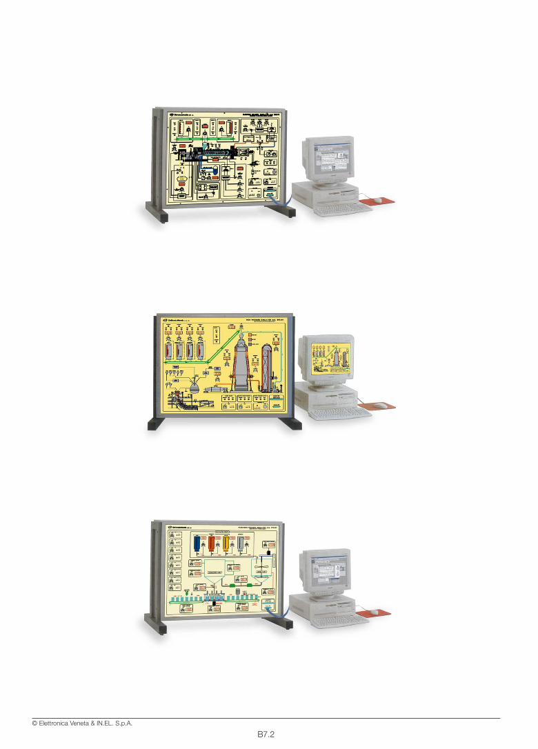
B7.2© Elettronica Veneta & IN.EL. S.p.A.
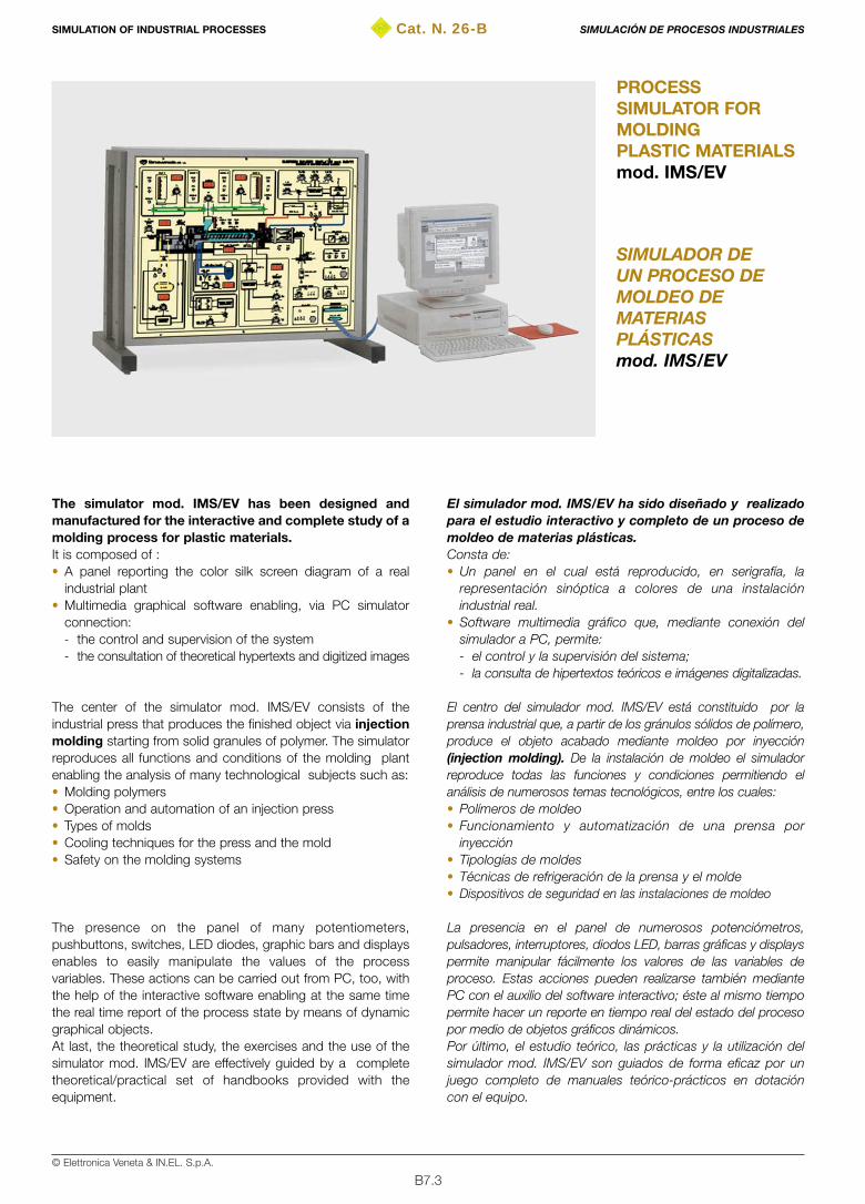
B7.3© Elettronica Veneta & IN.EL. S.p.A.
Cat. N. 26-B
SIMULADOR DEUN PROCESO DEMOLDEO DEMATERIASPLÁSTICASmod. IMS/EV
PROCESSSIMULATOR FORMOLDINGPLASTIC MATERIALSmod. IMS/EV
The simulator mod. IMS/EV has been designed andmanufactured for the interactive and complete study of amolding process for plastic materials.It is composed of : • A panel reporting the color silk screen diagram of a real
industrial plant• Multimedia graphical software enabling, via PC simulator
connection:- the control and supervision of the system- the consultation of theoretical hypertexts and digitized images
The center of the simulator mod. IMS/EV consists of theindustrial press that produces the finished object via injectionmolding starting from solid granules of polymer. The simulatorreproduces all functions and conditions of the molding plantenabling the analysis of many technological subjects such as:• Molding polymers• Operation and automation of an injection press• Types of molds• Cooling techniques for the press and the mold• Safety on the molding systems
The presence on the panel of many potentiometers,pushbuttons, switches, LED diodes, graphic bars and displaysenables to easily manipulate the values of the processvariables. These actions can be carried out from PC, too, withthe help of the interactive software enabling at the same timethe real time report of the process state by means of dynamicgraphical objects.At last, the theoretical study, the exercises and the use of thesimulator mod. IMS/EV are effectively guided by a completetheoretical/practical set of handbooks provided with theequipment.
El simulador mod. IMS/EV ha sido diseñado y realizadopara el estudio interactivo y completo de un proceso demoldeo de materias plásticas.Consta de:• Un panel en el cual está reproducido, en serigrafía, la
representación sinóptica a colores de una instalaciónindustrial real.
• Software multimedia gráfico que, mediante conexión delsimulador a PC, permite: - el control y la supervisión del sistema;- la consulta de hipertextos teóricos e imágenes digitalizadas.
El centro del simulador mod. IMS/EV está constituido por laprensa industrial que, a partir de los gránulos sólidos de polímero,produce el objeto acabado mediante moldeo por inyección(injection molding). De la instalación de moldeo el simuladorreproduce todas las funciones y condiciones permitiendo elanálisis de numerosos temas tecnológicos, entre los cuales:• Polímeros de moldeo• Funcionamiento y automatización de una prensa por
inyección• Tipologías de moldes• Técnicas de refrigeración de la prensa y el molde• Dispositivos de seguridad en las instalaciones de moldeo
La presencia en el panel de numerosos potenciómetros,pulsadores, interruptores, diodos LED, barras gráficas y displayspermite manipular fácilmente los valores de las variables deproceso. Estas acciones pueden realizarse también mediantePC con el auxilio del software interactivo; éste al mismo tiempopermite hacer un reporte en tiempo real del estado del procesopor medio de objetos gráficos dinámicos.Por último, el estudio teórico, las prácticas y la utilización delsimulador mod. IMS/EV son guiados de forma eficaz por unjuego completo de manuales teórico-prácticos en dotacióncon el equipo.
SIMULATION OF INDUSTRIAL PROCESSES SIMULACIÓN DE PROCESOS INDUSTRIALES

B7.4© Elettronica Veneta & IN.EL. S.p.A.
TRAINING PROGRAMThe simulator mod. IMS/EV enables the study of the followingmain subjects:• Structure of a molding system • Molding materials• Structure, operation and automation of the industrial injection
press• Extrusion process • Injection process• Press cooling systems• Types of molds• Mold blocking systems• Mold cooling systems• Mold cooling times• Quality control (QC) of the finished object• Safety of the molding plants• Emergency and alarms• Monitoring and control of the molding process via PC
TECHNICAL SPECIFICATIONS• Sheet steel structure, chemically treated and painted with
epoxy paint • Colored silk-screen panel representing the plant• Setting and manipulation of the process variables via:
- potentiometers- pushbuttons- switches
• Visualization of the process variables via:- LED diodes- bargraph- display
• Electronic card for control of the digital and analog I/O on thesimulator provided with serial interface RS-232 forcommunication with PC
• RS-232 cable for simulator/PC communication
DIMENSIONS900x710x450 mm
POWER SUPPLY115/230 V ±10% – 50/60 Hz
MULTIMEDIA SOFTWAREGraphical software for supervision and service enabling:• Real-time display of the process dynamics• Sending of commands to the simulator• Manipulation of the process variables• Definition of graphs and tables• Creation of databases concerning the process• Process diagnostics• Consulting of hypertexts and digitized images
THEORETICAL-EXPERIMENTAL HANDBOOKS • Theoretical-experimental handbook with guide to the exercises• Installation, use and maintenance handbook
PROGRAMA DE FORMACIÓNEl simulador mod. IMS/EV permite el estudio de los siguientesprincipales temas:• Estructura de una instalación de moldeo• Materiales de moldeo• Estructura, funcionamiento y automatización de la prensa
industrial por inyección• Proceso de extrusión• Proceso de inyección• Sistemas de refrigeración de la prensa• Tipologías de moldes• Sistemas de bloqueo del molde• Sistemas de refrigeración del molde• Tiempos de refrigeración del molde• Control de calidad (CQ) del objeto acabado• Seguridad en las instalaciones de moldeo• Emergencias y alarmas• Monitorización y control del proceso de moldeo mediante PC
CARACTERÍSTICAS TÉCNICAS• Estructura exterior en acero tratado químicamente y pintada
con barniz epoxi• Panel serigrafiado con representación sinóptica a colores de
la instalación• Predisposición y manipulación de las variables de proceso
mediante:- potenciómetros- pulsadores- interruptores
• Visualización de las variables de proceso mediante:- diodos LED - barras gráficas- displays
• Tarjeta electrónica de control E/S digitales y analógicaspresentes en el simulador provista de interfaz serie RS-232para comunicación con PC
• Cable RS-232 de comunicación simulador/PC
DIMENSIONES900x710x450 mm
ALIMENTACIÓN115/230 Vca ±10% – 50/60 Hz
SOFTWARE MULTIMEDIASoftware gráfico de supervisión y servicio que permite:• Visualización real-time de la dinámica del proceso• Envío de mandos al simulador • Manipulación de las variables de proceso • Definición de gráficos y tablas• Creación de bases de datos inherentes al proceso• Diagnóstico del proceso• Consultación de hipertextos e imágenes digitalizadas
TEXTOS TEÓRICO-PRÁCTICOS• Manual de teoría y prácticas• Manual de instalación, utilización y mantenimiento
SIMULATION OF INDUSTRIAL PROCESSES SIMULACIÓN DE PROCESOS INDUSTRIALES
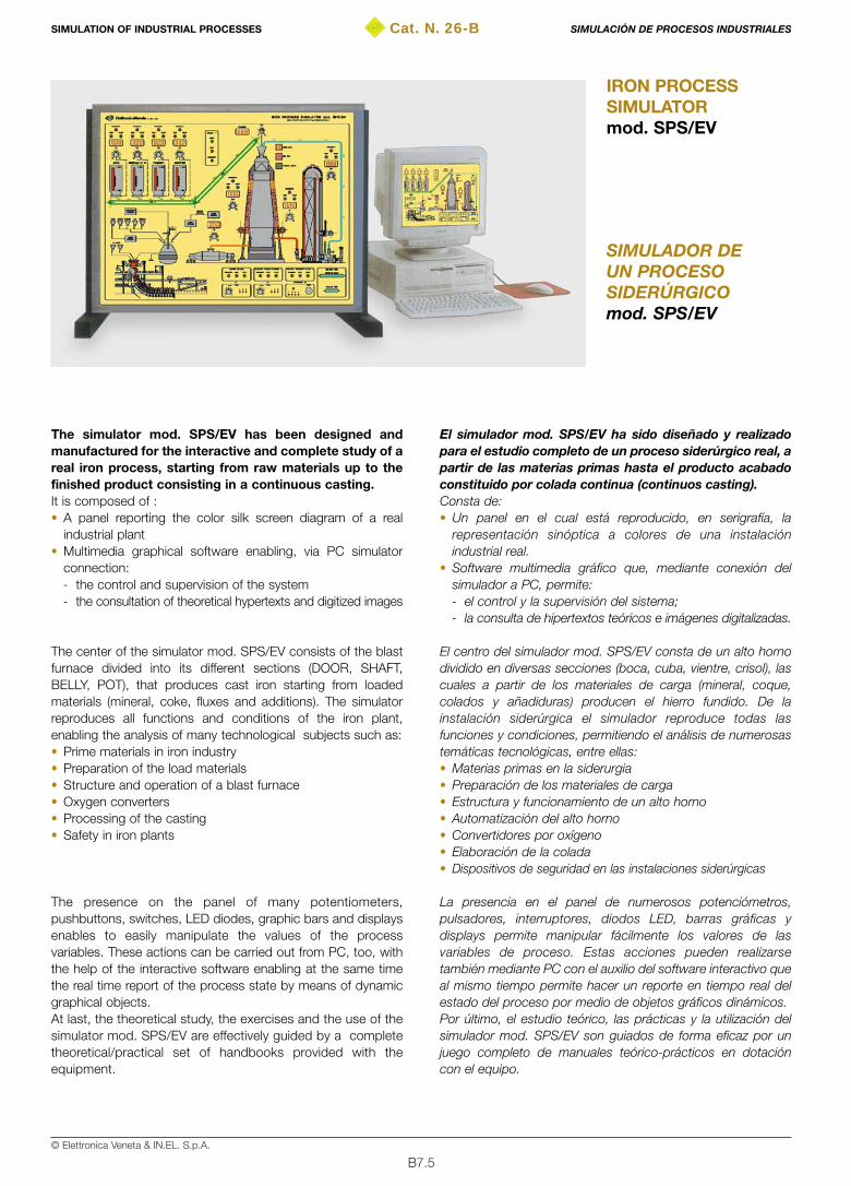
B7.5© Elettronica Veneta & IN.EL. S.p.A.
Cat. N. 26-B
SIMULADOR DEUN PROCESOSIDERÚRGICOmod. SPS/EV
IRON PROCESSSIMULATORmod. SPS/EV
The simulator mod. SPS/EV has been designed andmanufactured for the interactive and complete study of areal iron process, starting from raw materials up to thefinished product consisting in a continuous casting.It is composed of : • A panel reporting the color silk screen diagram of a real
industrial plant• Multimedia graphical software enabling, via PC simulator
connection:- the control and supervision of the system- the consultation of theoretical hypertexts and digitized images
The center of the simulator mod. SPS/EV consists of the blastfurnace divided into its different sections (DOOR, SHAFT,BELLY, POT), that produces cast iron starting from loadedmaterials (mineral, coke, fluxes and additions). The simulatorreproduces all functions and conditions of the iron plant,enabling the analysis of many technological subjects such as:• Prime materials in iron industry • Preparation of the load materials • Structure and operation of a blast furnace • Oxygen converters • Processing of the casting• Safety in iron plants
The presence on the panel of many potentiometers,pushbuttons, switches, LED diodes, graphic bars and displaysenables to easily manipulate the values of the processvariables. These actions can be carried out from PC, too, withthe help of the interactive software enabling at the same timethe real time report of the process state by means of dynamicgraphical objects.At last, the theoretical study, the exercises and the use of thesimulator mod. SPS/EV are effectively guided by a completetheoretical/practical set of handbooks provided with theequipment.
El simulador mod. SPS/EV ha sido diseñado y realizadopara el estudio completo de un proceso siderúrgico real, apartir de las materias primas hasta el producto acabadoconstituido por colada continua (continuos casting).Consta de:• Un panel en el cual está reproducido, en serigrafía, la
representación sinóptica a colores de una instalaciónindustrial real.
• Software multimedia gráfico que, mediante conexión delsimulador a PC, permite: - el control y la supervisión del sistema;- la consulta de hipertextos teóricos e imágenes digitalizadas.
El centro del simulador mod. SPS/EV consta de un alto hornodividido en diversas secciones (boca, cuba, vientre, crisol), lascuales a partir de los materiales de carga (mineral, coque,colados y añadiduras) producen el hierro fundido. De lainstalación siderúrgica el simulador reproduce todas lasfunciones y condiciones, permitiendo el análisis de numerosastemáticas tecnológicas, entre ellas:• Materias primas en la siderurgia• Preparación de los materiales de carga• Estructura y funcionamiento de un alto horno • Automatización del alto horno• Convertidores por oxígeno• Elaboración de la colada• Dispositivos de seguridad en las instalaciones siderúrgicas
La presencia en el panel de numerosos potenciómetros,pulsadores, interruptores, diodos LED, barras gráficas ydisplays permite manipular fácilmente los valores de lasvariables de proceso. Estas acciones pueden realizarsetambién mediante PC con el auxilio del software interactivo queal mismo tiempo permite hacer un reporte en tiempo real delestado del proceso por medio de objetos gráficos dinámicos.Por último, el estudio teórico, las prácticas y la utilización delsimulador mod. SPS/EV son guiados de forma eficaz por unjuego completo de manuales teórico-prácticos en dotacióncon el equipo.
SIMULATION OF INDUSTRIAL PROCESSES SIMULACIÓN DE PROCESOS INDUSTRIALES

B7.6© Elettronica Veneta & IN.EL. S.p.A.
TRAINING PROGRAMThe simulator mod. SPS/EV enables the study of the followingmain subjects:• Prime materials in iron industry • Structure of a blast furnace • Operation and automation of a blast furnace • Preparation of the load materials • Cokery materials and sub-products • Recirculation of the cokery and blast furnace gases• Taking and transport of cast iron: torpedo truck• Steel production • Structure and operation of the converter with oxygen thrower• Structure and operation of the ladle • Processing of the casting• Continuous casting: production of flat blooms• Safety in iron plants• Emergency and alarms• Monitoring and control of the iron process via PC
TECHNICAL SPECIFICATIONS• Sheet steel structure, chemically treated and painted with
epoxy paint • Colored silk-screen panel representing the plant• Setting and manipulation of the process variables via:
- potentiometers- pushbuttons- switches
• Visualization of the process variables via:- LED diodes- bargraph- display
• Electronic card for control of the digital and analog I/O on thesimulator provided with serial interface RS-232 forcommunication with PC
• RS-232 cable for simulator/PC communication
DIMENSIONS900x710x450 mm
POWER SUPPLY115/230 V ±10% – 50/60 Hz
MULTIMEDIA SOFTWAREGraphical software for supervision and service enabling:• Real-time display of the process dynamics• Sending of commands to the simulator• Manipulation of the process variables• Definition of graphs and tables• Creation of databases concerning the process• Process diagnostics• Consulting of hypertexts and digitized images
THEORETICAL-EXPERIMENTAL HANDBOOKS • Theoretical-experimental handbook with guide to the exercises• Installation, use and maintenance handbook
PROGRAMA DE FORMACIÓNEl simulador mod. SPS/EV permite el estudio de los siguientesprincipales temas:• Materias primas en la industria siderúrgica• Estructura de un alto horno• Funcionamiento y automatización de un alto horno• Preparación de los materiales de carga• Materiales y subproductos de coquería• Reciclo de los gases de coquería y alto horno • Cogida y transporte del hierro fundido: vagonetas• Producción del acero• Estructura y funcionamiento del convertidor por lanza de oxígeno• Estructura y funcionamiento del caldero de colada• Elaboración de la colada• Colada continua: producción de los desbastes planos• Seguridad en las instalaciones siderúrgicas• Emergencias y alarmas• Monitorización y control del proceso siderúrgico mediante PC
CARACTERÍSTICAS TÉCNICAS• Estructura exterior en acero tratado químicamente y pintada
con barniz epoxi• Panel serigrafiado con representación sinóptica de colores
de la instalación• Predisposición y manipulación de las variables de proceso
mediante:- potenciómetros- pulsadores- interruptores
• Visualización de las variables de proceso mediante:- diodos LED - barras gráficas- displays
• Tarjeta electrónica de control E/S digitales y analógicaspresentes en el simulador provista de interfaz serie RS-232para comunicación con PC
• Cable RS-232 de comunicación simulador/PC
DIMENSIONES900x710x450 mm
ALIMENTACIÓN115/230 Vca ±10% – 50/60 Hz
SOFTWARE MULTIMEDIASoftware gráfico de supervisión y servicio que permite:• Visualización real-time de la dinámica del proceso• Envío de mandos al simulador • Manipulación de las variables de proceso • Definición de gráficos y tablas• Creación de bases de datos inherentes al proceso• Diagnóstico del proceso• Consultación de hipertextos e imágenes digitalizadas
TEXTOS TEÓRICO-PRÁCTICOS• Manual de teoría y prácticas• Manual de instalación, utilización y mantenimiento
SIMULATION OF INDUSTRIAL PROCESSES SIMULACIÓN DE PROCESOS INDUSTRIALES
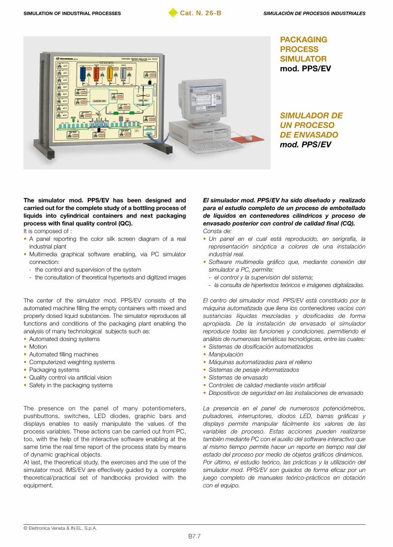
B7.7© Elettronica Veneta & IN.EL. S.p.A.
Cat. N. 26-B
SIMULADOR DEUN PROCESODE ENVASADOmod. PPS/EV
PACKAGINGPROCESSSIMULATORmod. PPS/EV
The simulator mod. PPS/EV has been designed andcarried out for the complete study of a bottling process ofliquids into cylindrical containers and next packagingprocess with final quality control (QC).It is composed of : • A panel reporting the color silk screen diagram of a real
industrial plant• Multimedia graphical software enabling, via PC simulator
connection:- the control and supervision of the system - the consultation of theoretical hypertexts and digitized images
The center of the simulator mod. PPS/EV consists of theautomated machine filling the empty containers with mixed andproperly dosed liquid substances. The simulator reproduces allfunctions and conditions of the packaging plant enabling theanalysis of many technological subjects such as:• Automated dosing systems• Motion• Automated filling machines • Computerized weighting systems • Packaging systems• Quality control via artificial vision• Safety in the packaging systems
The presence on the panel of many potentiometers,pushbuttons, switches, LED diodes, graphic bars anddisplays enables to easily manipulate the values of theprocess variables. These actions can be carried out from PC,too, with the help of the interactive software enabling at thesame time the real time report of the process state by meansof dynamic graphical objects.At last, the theoretical study, the exercises and the use of thesimulator mod. IMS/EV are effectively guided by a completetheoretical/practical set of handbooks provided with theequipment.
El simulador mod. PPS/EV ha sido diseñado y realizadopara el estudio completo de un proceso de embotelladode líquidos en contenedores cilíndricos y proceso deenvasado posterior con control de calidad final (CQ).Consta de:• Un panel en el cual está reproducido, en serigrafía, la
representación sinóptica a colores de una instalaciónindustrial real.
• Software multimedia gráfico que, mediante conexión delsimulador a PC, permite: - el control y la supervisión del sistema;- la consulta de hipertextos teóricos e imágenes digitalizadas.
El centro del simulador mod. PPS/EV está constituido por lamáquina automatizada que llena los contenedores vacíos consustancias líquidas mezcladas y dosificadas de formaapropiada. De la instalación de envasado el simuladorreproduce todas las funciones y condiciones, permitiendo elanálisis de numerosas temáticas tecnológicas, entre las cuales:• Sistemas de dosificación automatizados• Manipulación• Máquinas automatizadas para el relleno• Sistemas de pesaje informatizados• Sistemas de envasado• Controles de calidad mediante visión artificial• Dispositivos de seguridad en las instalaciones de envasado
La presencia en el panel de numerosos potenciómetros,pulsadores, interruptores, diodos LED, barras gráficas ydisplays permite manipular fácilmente los valores de lasvariables de proceso. Estas acciones pueden realizarsetambién mediante PC con el auxilio del software interactivo queal mismo tiempo permite hacer un reporte en tiempo real delestado del proceso por medio de objetos gráficos dinámicos.Por último, el estudio teórico, las prácticas y la utilización delsimulador mod. PPS/EV son guiados de forma eficaz por unjuego completo de manuales teórico-prácticos en dotacióncon el equipo.
SIMULATION OF INDUSTRIAL PROCESSES SIMULACIÓN DE PROCESOS INDUSTRIALES

B7.8© Elettronica Veneta & IN.EL. S.p.A.
TRAINING PROGRAMThe simulator mod. PPS/EV enables the study of the followingmain subjects:• Industrial packaging plants• Automated dosing of liquid and solid substances• Mixers of liquid substances• Inner motion systems• Structure and automation of a filling machine• Computerized weighting systems in line• Mechanical and artificial vision quality control • Marking and labeling systems• Cartons preparation for packaging process• Packaging of the containers into the cartons• Cartons palletting• Logistics• Safeties on the packaging plants• Emergency and alarms• Monitoring and control of the iron process via PC
TECHNICAL SPECIFICATIONS• Sheet steel structure, chemically treated and painted with
epoxy paint • Colored silk-screen panel representing the plant• Setting and manipulation of the process variables via:
- potentiometers- pushbuttons- switches
• Visualization of the process variables via:- LED diodes- bargraph- display
• Electronic card for control of the digital and analog I/O on thesimulator provided with serial interface RS-232 forcommunication with PC
• RS-232 cable for simulator/PC communication
DIMENSIONS900x710x450 mm
POWER SUPPLY115/230 V ±10% – 50/60 Hz
MULTIMEDIA SOFTWAREGraphical software for supervision and service enabling:• Real-time display of the process dynamics• Sending of commands to the simulator• Manipulation of the process variables• Definition of graphs and tables• Creation of databases concerning the process• Process diagnostics• Consulting of hypertexts and digitized images
THEORETICAL-EXPERIMENTAL HANDBOOKS • Theoretical-experimental handbook with guide to the exercises• Installation, use and maintenance handbook
PROGRAMA DE FORMACIÓNEl simulador mod. PPS/EV permite el estudio de los siguientesprincipales temas:• Instalaciones industriales de envasado• Dosificación automatizada de sustancias líquidas y sólidas• Mezcladores de sustancias líquidas• Sistemas de manipulación interior• Estructura y automatización de una máquina de llenado• Sistemas de pesaje informatizados en línea• Controles de calidad mecánicos y de visión artificial• Sistemas de marcado y etiquetado• Preparación de los envases para el proceso de envasado• Envasado de los contenedores en los envases• Palletización de los envases• Logística • Seguridad en las instalaciones de envasado• Emergencias y alarmas• Monitorización y control del proceso siderúrgico mediante PC
CARACTERÍSTICAS TÉCNICAS• Estructura exterior en acero tratado químicamente y pintada
con barniz epoxi• Panel serigrafiado con representación sinóptica de colores
de la instalación• Predisposición y manipulación de las variables de proceso
mediante:- potenciómetros- pulsadores- interruptores
• Visualización de las variables de proceso mediante:- diodos LED - barras gráficas- displays
• Tarjeta electrónica de control E/S digitales y analógicaspresentes en el simulador provista de interfaz serie RS-232para comunicación con PC
• Cable RS-232 de comunicación simulador/PC
DIMENSIONES900x710x450 mm
ALIMENTACIÓN115/230 Vca ±10% – 50/60 Hz
SOFTWARE MULTIMEDIASoftware gráfico de supervisión y servicio que permite:• Visualización real-time de la dinámica del proceso• Envío de mandos al simulador • Manipulación de las variables de proceso • Definición de gráficos y tablas• Creación de bases de datos inherentes al proceso• Diagnóstico del proceso• Consultación de hipertextos e imágenes digitalizadas
TEXTOS TEÓRICO-PRÁCTICOS• Manual de teoría y prácticas• Manual de instalación, utilización y mantenimiento
SIMULATION OF INDUSTRIAL PROCESSES SIMULACIÓN DE PROCESOS INDUSTRIALES

B8.1© Elettronica Veneta & IN.EL. S.p.A.
PAGE
MECHANICAL PROTOTYPING B8.1
Laboratory for mechanical prototypingmod. LPM/EV B8.3
PÁG.
PROTOTIPACIÓN MECÁNICA B8.1
Laboratorio para la prototipación mecánicamod. LPM/EV B8.3
Cat. N. 26-BMECHANICAL PROTOTYPING PROTOTIPACIÓN MECÁNICA

B8.2© Elettronica Veneta & IN.EL. S.p.A.
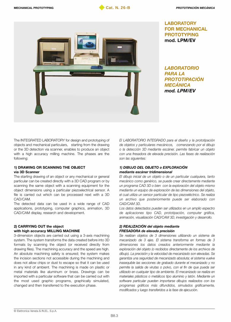
B8.3© Elettronica Veneta & IN.EL. S.p.A.
Cat. N. 26-B
LABORATORIOPARA LAPROTOTIPACIÓNMECÁNICAmod. LPM/EV
LABORATORYFOR MECHANICALPROTOTYPINGmod. LPM/EV
The INTEGRATED LABORATORY for design and prototyping ofobjects and mechanical particulars, starting from the drawingor the 3D detection via scanner, enables to produce an objectwith a high accuracy milling machine. The phases are thefollowing:
1) DRAWING OR SCANNING THE OBJECTvia 3D Scanner The starting drawing of an object or any mechanical or generalparticular can be created directly with a 3D CAD program or byscanning the same object with a scanning equipment for theobject dimensions using a particular piezoelectrical sensor. Afile is carried out which can be processed next with a 3DCAD/CAM.The detected data can be used in a wide range of CADapplications, prototyping, computer graphics, animation, 3DCAD/CAM display, research and development.
2) CARRYING OUT the objectwith high accuracy MILLING MACHINE3-dimension objects are carried out using a 3-axis machiningsystem. The system transforms the data created before into 3Dformats by scanning the object (or received directly fromdrawing files). The machining accuracy and the speed are high.An absolute machining safety is ensured; the system makesthe incision sections not accessible during the machining anddoes not allow chips or dust to escape so that it can be usedin any kind of ambient. The machining is made on plastic ormetal materials like aluminum or brass. Drawings can beimported with a particular software that can be carried out withthe most used graphic programs, graphically simulated,changed and then transferred to the execution phase.
El LABORATORIO INTEGRADO para el diseño y la prototipaciónde objetos y particulares mecánicos, comenzando por el dibujoo la detección 3D mediante escáner, permite fabricar un objetocon una fresadora de elevada precisión. Las fases de realizaciónson las siguientes:
1) DIBUJO DEL OBJETO o EXPLORACIÓNmediante escáner tridimensionalEl dibujo inicial de un objeto o de un particular cualquiera, tantomecánico como genérico, se puede crear directamente medianteun programa CAD 3D o bien con la exploración del objeto mismomediante un equipo de exploración de las dimensiones del objeto,el cual utiliza un sensor particular de tipo piezoeléctrico. Se realizaun archivo que posteriormente puede ser elaborado conCAD/CAM 3D.Los datos detectados pueden ser utilizados en un amplio espectrode aplicaciones tipo CAD, prototipación, computer gráfica,animación, visualización CAD/CAM 3D, investigación y desarrollo.
2) REALIZACIÓN del objeto medianteFRESADORA de elevada precisiónSe realizan objetos de 3 dimensiones utilizando un sistema demecanizado de 3 ejes. El sistema transforma en formas de 3dimensiones los datos creados anteriormente mediante laexploración del objeto (o recibidos directamente de los archivos dedibujo). La precisión y la velocidad de mecanizado son elevadas. Segarantiza una seguridad de mecanizado absoluta; el sistema vuelveinasequible las secciones de grabado durante el mecanizado y nopermite la salida de virutas o polvo, con el fin de que pueda serutilizado en cualquier tipo de ambiente. El mecanizado se realiza enmateriales plásticos o metálicos tipo aluminio y latón. Mediante unsoftware particular pueden importarse dibujos realizados con losprogramas gráficos más difundidos, simulados gráficamente,modificados y luego transferidos a la fase de ejecución.
MECHANICAL PROTOTYPING PROTOTIPACIÓN MECÁNICA

B8.4© Elettronica Veneta & IN.EL. S.p.A.
TRAINING PROGRAMCAD procedure• Carrying out and editing mechanical drawings• Use of the set of graphical base units for manufacturing of
complex drawings• Conversion of standard drawing into different formatsScanner• 3D analysis of the objects or mechanical particulars• Detection accuracy • De-composition of mechanic particulars into component
sections • Assembling/composition of sections of mechanical particulars • CAD applications/integration of the detected data • 3D display, animation, graphical processing of the detected data3-axis modeling• Structure and general operation of the programmable
numerical control machines • Programming and control of the tools in a programmable
numerical control machine• Machining examples
TECHNICAL SPECIFICATIONSCAD PROCEDUREProfessional level drawing program for production of highdefinition and flexibility works:• Complete compatibility with the drawings related to the
different AutoCAD versions• Drawing file exchange inside a work group with integrity of
data and graphical fidelity of drawings• Very easy, fast and accurate changing of the objects
properties • Re-use of last drawings• Best use of the existent data • More control and flexibility while creating drawings thanks to
the multiple lay-out function
OBJECT DETECTION SCANNER for MECHANICALPROTOTYPING Scanning of the starting object through piezo scan system withgeneration of the graphic program of the object that can bechanged also from CAD procedure.• Scan area: 304.8 mm [X] x 203.2 mm [Y] x 60.5 mm [Z]• Possibility to scan the soft and transparent objects• Maximum weight of the object to be detected: 5 kg• Piezo sensor• Scan method: contact, nest of points• Scan step: X/Y-axes direction – 0.05-5.00 mm (settable with
steps of 0.05 mm) Z axis – 0.025 mm• Scan speed: XY axes: 30 mm/sec, Z axis: 9 mm/sec• Exportable file formats: DXF, VRML, STL, 3DMF, BMP,
Grayscale, Point Group• Interface with Personal Computer: serial (RS-232C)• Consumption: dedicated AC adapter (DC + 12V, 1.5A)• Acoustic emission: Standby: <40dB (A); in scanning: <50 dB (A)• Dimensions: 478 mm (width) x 465 mm (depth) x 341 mm (height)• Weight: 11 kg• Operating temperature: 5–40 °C• Operating humidity: 35–80%
PROGRAMA DE FORMACIÓNSoftware CAD• Realización y edición de dibujos mecánicos• Utilización de la serie de entidades de base gráficas para la
construcción de dibujos complejos• Conversión en los diferentes formatos de dibujo estándarEscáner• Análisis 3D de los objetos o particulares mecánicos• Precisión de detección• Descomposición de particulares mecánicos en las secciones
que los constituyen• Ensamblaje/composición de sección de particulares mecánicos• Aplicaciones/integración CAD de datos detectados• Visualización 3D, animación, elaboración gráfica de los datos
detectadosModelado de 3 ejes• Estructura y funcionamiento general de las máquinas de control
numérico programable• Programación y gestión de las herramientas en una máquina de
control numérico programable• Ejemplos de mecanizado
CARACTERÍSTICAS TÉCNICASSOFTWARE CADPrograma de diseño de nivel profesional para realizar trabajos conalta definición y flexibilidad:• Compatibilidad total con los dibujos correspondientes a las
distintas versiones AutoCAD• Intercambio de archivos de diseño en el interior de un grupo de
trabajo con integridad de datos y fidelidad gráfica de los dibujos• Modificación de las propiedades de los objetos en modo fácil,
rápido y preciso• Reutilización de dibujos anteriores• Uso óptimo de los datos existentes• Mayor control y flexibilidad durante la composición de los
dibujos, gracias a la función lay-out múltiple
ESCÁNER DE DETECCIÓN DE OBJETOS paraPROTIPACIÓN MECÁNICAExploración del objeto inicial mediante sistema de exploraciónpiezo con generación del programa gráfico del objeto modificabletambién con sofware CAD.• Área de exploración: 304,8 mm [X] x 203,2 mm [Y] x 60,5 mm [Z]• Posibilidad de exploración de objetos blandos y transparentes• Peso máximo del objeto por detectar: 5 kg• Sensor Piezo• Método de exploración: Contacto, nube de puntos• Paso exploración: Dirección ejes X/Y – 0,05-5,00 mm
(seleccionables por pasos de 0,05 mm) eje Z – 0,025 mm• Velocidad de exploración: Ejes XY: 30 mm/seg, Eje Z: 9 mm/seg• Formatos archivos exportables: DXF, VRML, STL, 3DMF, BMP,
Grayscale, Point Group• Interfaz con ordenador personal: serie (RS-232C)• Consumo: adaptador CA dedicado (DC + 12V, 1,5A)• Emisión acústica: Standby: <40dB (A); en exploración: <50 dB (A)• Dimensiones: 478 mm (anchura) x 465 mm (profundidad) x 341
mm (altura)• Peso: 11 kg• Temperatura de funcionamiento: 5–40 °C• Humedad de funcionamiento: 35–80%
MECHANICAL PROTOTYPING PROTOTIPACIÓN MECÁNICA
B8.5© Elettronica Veneta & IN.EL. S.p.A.
SCANNER acquisition softwareScan software projected for a simple use of the equipment:• Possibility of reducing the number of acquired data dropping
the resolution of all or a part of the digitized surface andspecific scanning of another part of the object with a higherdefinition different from the last
• Combination of acquired sections with different definition • Setting of the area to be digitized • Setting of the scan paths X and Y• Multiple formats of output data files: DXF (CAD data), STL
and 3DMF (3D standard format), ASCII with compatibility tothe most common applications (X, Y, Z coordinate text data)
3-AXIS MODELING SYSTEM The system consists of a 3D CAMM (Computer Aided ModelingMachine) unit transforming the detection files from scanner into3D physical objects • Operating dimensions: X axis: 120 mm, Y axis: 100 mm,
Z axis: 120 mm• Spindle motor: 26 W (d.c. motor)• Spindle rotation speed: 3000- 8000 rpm (with manual control
or with controls via instructions)• Tool holder: 6mm standard neck system• Minimum operating speed: X & Y axis: 3.6 m/min; Z axis:
1.8 m/min• Maximum operating speed: 0.03 m/min• Software resolution: 0.01 mm/step or 0.025 mm/step• Used materials: chemical wood, modeling foam, resins, light
not ferrous materials like aluminum and brass • Control functions for X- and Y-axis smoothing• Interface with Personal Computer: parallel (Centronics) or
serial (RS-232C)• Instruction system: CAMM-GLI (Mode 1: compatible with
series CAMM-2 and CAMM-3 of Roland. Mode 2: HP-GLemulation, plotter format 0.025 mm)
• Safety: safety covering, Emergency / Stop pushbutton• Buffer memory: 1KB expandable up to 1 MB• LCD display: 20 letters x 2 lines (display with rear illumination)• Operating temperature and humidity: 5-40 °C, 35-80%• Absorption: 1.7A / 117 V, 1.0A / 220-230 V, 0.9A / 240 V• Dimensions: 490x516x430 mm• Weight: 36 kg• Acoustic emission: in Standby: <55dB (A); in execution:
<60 dB (A)
Modeling softwareIntuitive control of 3D machining of different objects such asplates, raised models, prototypes• Immediate processing of bidimensional models• Dedicated postprocessor simple to handle • Files importing into 3D DXF and STL format• Creation of the tool path • Support of modeling languages RML-1 and numerical
control tool (code G) to use with 3D CAD/CAM software• Manual control on each axis • Z0 sensor enabling the automatic setting of the origin point Z
Software de adquisición por ESCÁNERSoftware de exploración diseñado para una fácil utilización del equipo:• Posibilidad de reducir el número de los datos adquiridos
disminuyendo la resolución de toda o de una parte de lasuperficie digitalizada y exploración específica de otra parte delobjeto a una definición más elevada diferente de la anterior
• Combinación de secciones adquiridas a definición diferente• Selección del área por digitalizar• Selección de los pasos de exploración X e Y• Múltiples formatos de file data de salida: DXF (CAD data), STL y
3DMF (3D formato estándar), ASCII con compatibilidad con lasaplicaciones más comunes (X, Y, Z coordenadas text data)
SISTEMA DE MODELADO de 3 EJESEl sistema consta de una unidad 3D CAMM (Computer AidedModelling Machine) que los archivos detectados con el escánertransforma en objetos físicos 3D.• Dimensiones de operación: eje X: 120 mm, eje Y: 100 mm, eje
Z: 120 mm• Motor del husillo: 26 W (motor de corriente continua)• Velocidad de rotación del husillo: 3.000-8.000 r.p.m.
(controlable manualmente o mediante instrucciones)• Porta-herramienta: sistema de garganta de 6mm estándar• Velocidad mínima de operación: ejes X e Y: 3,6 m/min; eje Z:
1,8 m/min• Velocidad máxima de operación: 0,03 m/min• Resolución software: 0,01 mm/step ó 0,025 mm/step• Materiales utilizables: madera química, espuma para modelar,
resinas, metales ligeros no ferrosos tipo aluminio y latón• Funciones de control pulido ejes X Y • Interfaz con ordenador personal: paralelo (Centronics) o serie
(RS-232C)• Sistema de instrucciones: CAMM-GLI (Modo 1: compatible con
serie CAMM-2 y CAMM-3 de Roland. Modo 2: emulaciónHP-GL, formato plotter 0,025 mm)
• Dispositivos de seguridad: cubierta de seguridad, pulsador deEmergencia/Stop
• Memoria buffer: 1KB ampliable hasta 1 MB• Display: LCD: 20 letras x 2 líneas (display con retroiluminación)• Temperatura y humedad de operación: 5-40 °C, 35-80%• Absorción: 1,7A / 117 V, 1,0A / 220-230 V, 0,9 A / 240 V• Dimensiones: 490 x 516 x 430 mm• Peso: 36 kg• Emisión acústica: en Standby: <55dB (A); en ejecución: <60 dB (A)
Software de modeladoGestión intuitiva de mecanizados tridimensionales de distintosobjetos como placas, modelos en relieve, prototipos.• Inmediata elaboración de modelos bidimensionales• Postprocesador dedicado y fácil de controlar• Importación de archivos en formato tridimensional DXF y STL• Creación del recorrido de la herramienta• Soporte de lenguajes de modelado RML-1 y código de control
numérico (código G) para la utilización con softwarestridimensionales CAD/CAM
• Control manual de cada eje• Sensor Z0 que permite la selección automática del punto de
origen Z
MECHANICAL PROTOTYPING PROTOTIPACIÓN MECÁNICA

B8.6© Elettronica Veneta & IN.EL. S.p.A.
Personal Computer Multimedia • 700-MHz microprocessor Intel Pentium III or superior• RAM >= 64 Mb PC133• Hard Disk >= 10 GB UDMA • Parallel interface, 2 serial interfaces, 2 usb• Floppy 3.5” 1.44 Mb• CD-ROM 52X reader or superior• SVGA 15” color monitor> 0.27 dpi • Operative system: Windows 98 or superior
POWER SUPPLY• 230 V – 50/60 Hz
(115 V upon request)
THEORETICAL-EXPERIMENTAL HANDBOOKS • Theoretical-experimental handbook with guide to the exercises• Installation, use and maintenance handbook
Ordenador personal multimedia• Microprocesador Intel Pentium III de 700 MHz o superior• Memoria RAM >= 64 Mb PC133• Disco duro >= 10 GB UDMA • Interfaz paralelo, 2 serie, 2 USB• Disquete 3,5” 1,44 Mb• Lector CD-ROM 52X o superior• Pantalla de color SVGA 15” > 0,27 dpi • Sistema operativo Windows 98 o superior
ALIMENTACIÓN• 230 V – 50/60 Hz
(115 V bajo pedido)
TEXTOS TEÓRICO-PRÁCTICOS• Manuales teóricos-prácticos con guía para las prácticas• Manual de instalación, utilización y mantenimiento
MECHANICAL PROTOTYPING PROTOTIPACIÓN MECÁNICA
23-A, 23-B
20-A
21-A, 21-B
35-A
33-A
34-A
38
39
27-A, 27-B
40
26 (26-A, 26-B, 26-C)
32-A, 32-B
25-A
24
37
36
29-A
“dedicated” / “dedicado”
22-A
PRESENTS
THE LIST OF THE CATALOGUES OF THE
“EXCELLENCE LABORATORIES”FOR THE TRAINING AND THE RESEARCH IN THE
THIRD MILLENNIUM
PRESENTA
LA LISTA DE CATÁLOGOS DE LOS
“LABORATORIOS DE EXCELENCIA”PARA LA FORMACIÓN Y LA INVESTIGACIÓN EN EL
TERCER MILENIO Catalogue
ELECTRICAL ENGINEERING
ELECTRONICS, INSTRUMENTATION
AND PROCESS CONTROL
TELECOMMUNICATIONS AND TELEMATIC
INTERACTIVE PRACTICAL ELECTRONIC SYSTEM
AUTOTRONICS
BIOMEDICAL EQUIPMENT
MAINTENANCE TECHNICIAN®
CONSUMER ELECTRONICS TECHNICIAN®
HYDRONICS
THERMOTRONICS
EDUCATIONAL CIB®
(Computer Integrated Building)
AUTOMATION TECHNOLOGIES
MECHATRONICS:
(CAD-CAM-CNC-FMS-CIM)
INDUSTRIAL PROCESS CONTROLS
INDUSTRIAL CHEMISTRY
EXPERIMENTAL CHEMISTRY LABORATORY
ECOLOGY
FOOD PROCESSING TECHNOLOGIES®
“HIGH TECH” MILITARY LABORATORY
MULTIMEDIA AUDIOVISUAL SYSTEMS
ELECTROTECNIA
ELECTRÓNICA Y
CONTROL DE PROCESOS
TELECOMUNICACIONES Y TELEMÁTICA
ELECTRÓNICA PRÁCTICA INTERACTIVA
AUTOTRÓNICA
MANTENIMIENTO DE
EQUIPOS ELECTROMÉDICOS®
MANTENIMIENTO DE ELECTRODOMÉSTICOS®
HIDRÓNICA
TERMOTRÓNICA
EDUCATIONAL CIB®
(Computer Integrated Building)
AUTOMATIZACIÓN
MECATRÓNICA:
(CAD-CAM-CNC-FMS-CIM)
CONTROL DE PROCESOS
QUÍMICA INDUSTRIAL
LABORATORIO DE QUÍMICA EXPERIMENTAL
ECOLOGÍA
FOOD-PROCESSING TECHNOLOGIES®
“HIGH TECH” MILITARY LABORATORY
SISTEMAS AUDIOVISUALES MULTIMEDIA


All rights reserved; no part of this publication may be reproduced, stored in any retrieval system, or transmitted in any form or by any means,electronic, mechanical, photocopying, recording, or otherwise without the prior written permission of Elettronica Veneta & IN.EL. S.p.A.
31045 MOTTA D I L IVENZA (T rev i so ) I t a l y – V i a Pos tum ia , 16Tel. 0422 7657 (r.a.) – Fax 0422 860784 – Export Tel. +39 0422 765802 Fax +39 0422 861901 – http://www.elettronicaveneta.com – E-mail: [email protected]
© Elettronica Veneta & IN.EL. S.p.A. 2002
Graphics and layout - Diseño gráfico y compaginaciónEditorial Coordinator and Promoter - Coordinador editorial y Promotor
Elettronica Veneta & IN.EL. - Marketing
Printed in Italy by GFP/Pn

Ripresa effettuata da satellite situato a 22.500 miglia dalla terra.A view from a satellite at 22,500 miles from the earth.
BOLOGNA
BOLOGNA
ROVIGO
PADOVA
MESTRE
S. DONÀDI PIAVE
CESSALTO
MOTTA DILIVENZA
CONEGLIANO
PORDENONE
PORTOGRUARO
TRIESTE
UDINE
VENEZIA
TREVISO
VICENZAVERONAMILANO
BRENNERO
FERRARA
Cat. n. 26-A
AUTOMATION TECHNOLOGIES
TECNOLOGÍAS DE LA AUTOMATIZACIÓN