mototrbo slr 5000 series repeater basic …...foreword this manual covers all versions of the...
TRANSCRIPT

MOTOTRBOTM SLR 5000 Series RepeaterBasic Service and Installation ManualM
*MN001437A01*MN001437A01-AA

ForewordThis manual covers all versions of the MOTOTRBO SLR 5000 Series Repeater, unless otherwise specified. It includes all the information necessary to maintain peak product performance and maximum working time, using levels 1 and 2 maintenance procedures. This level of service goes down to the module replacement level and is typical of some local service centers, Motorola Authorized Dealers, self-maintained customers, and distributors.
General Safety Precautions
See "General Safety and Installation Standards and Guidelines," on page iii.
Computer Software Copyrights
The Motorola products described in this manual may include copyrighted Motorola computer programs stored in semiconductor memories or other media. Laws in the United States and other countries preserve for Motorola certain exclusive rights for copyrighted computer programs, including, but not limited to, the exclusive right to copy or reproduce in any form the copyrighted computer program. Accordingly, any copyrighted Motorola computer programs contained in the Motorola products described in this manual may not be copied, reproduced, modified, reverse-engineered, or distributed in any manner without the express written permission of Motorola. Furthermore, the purchase of Motorola products shall not be deemed to grant either directly or by implication, estoppel, or otherwise, any license under the copyrights, patents or patent applications of Motorola, except for the normal non-exclusive license to use that arises by operation of law in the sale of a product.
Document Copyrights
No duplication or distribution of this document or any portion thereof shall take place without the express written permission of Motorola. No part of this manual may be reproduced, distributed, or transmitted in any form or by any means, electronic or mechanical, for any purpose without the express written permission of Motorola.
Disclaimer
The information in this document is carefully examined, and is believed to be entirely reliable. However, no responsibility is assumed for inaccuracies. Furthermore, Motorola reserves the right to make changes to any products herein to improve readability, function, or design. Motorola does not assume any liability arising out of the applications or use of any product or circuit described herein; nor does it cover any license under its patent rights nor the rights of others. Controlled copies of this document is available via Motorola On-Line (MOL).
Trademarks
MOTOROLA, MOTO, MOTOROLA SOLUTIONS and the Stylized M logo are trademarks or registered trademarks of Motorola Trademark Holdings, LLC and are used under license. All other trademarks are the property of their respective owners.
© 2015 Motorola Solutions, Inc.
All rights reserved.
These servicing instructions are for use by qualified personnel only. To reduce the risk of electric shock, do not perform any servicing other than that contained in the Operating Instructions unless you are qualified to do so. Refer all servicing to qualified service personnel.

General Safety and Installation Standards and Guidelines iii
General Safety and Installation Standards and Guidelines
ATTENTION!
WARNING: For safe installation, operation, service and repair of this equipment, follow the safety precautions and instructions described below, as well as any additional safety information in Motorola’s product service and installation manuals and the Motorola R56 Standards and Guidelines for Communications Sites manual. To obtain copies of these materials, please contact Motorola as directed at the end of this section. After installation, these instructions should be retained and readily available for any person operating or servicing this repeater or working near it.
Failure to follow these safety precautions and instructions could result in serious injury or property damage.
The installation process requires preparation and knowledge of the site before installation begins. Review installation procedures and precautions in the Motorola R56 manual before performing any site or component installation. Personnel must use safe work practices and good judgment, and always follow applicable safety procedures, such as requirements of the Occupational Safety and Health Administration (OSHA), the National Electrical Code (NEC), and local codes.
W A R N I N G

iv General Safety and Installation Standards and Guidelines
The following are additional general safety precautions that must be observed:
• To continue compliance with any applicable regulations and maintain the safety of this equipment, do not install substitute parts or perform any unauthorized modifications.
• All equipment must be serviced by Motorola trained personnel.
• If troubleshooting the equipment while the power is on, be aware of live circuits which could contain hazardous voltage.
• Do not operate the radio transmitters unless all RF connectors are secure and all connectors are properly terminated.
• All equipment must be properly grounded in accordance with the Motorola R56 and specified installation instructions for safe operation.
• Slots and openings in the cabinet are provided for ventilation. Do not block or cover openings that protect the devices from overheating.
• Some equipment components can become extremely hot during operation. Turn off all power to the equipment and wait until sufficiently cool before touching.
• Maintain emergency first aid kits at the site.
• Never store combustible materials in or near equipment racks. The combination of combustible material, heat and electrical energy increases the risk of a fire hazard.
Equipment shall be installed in a site that meets the requirements of a “restricted access location,” per (UL60950-1 & EN60950-1), which is defined as follows: "Access can only be gained by service persons or by users who have been instructed about the reasons for the restrictions applied to the location and about any precautions that shall be taken; and access is through the use of a tool or lock and key, or other means of security, and is controlled by the authority responsible for the location."
• Burn hazard. The metal housing of the product may become extremely hot. Use caution when working around the equipment.
• RF energy burn hazard. Disconnect power in the cabinet to prevent injury before disconnecting and connecting antennas.
• Shock hazard. The outer shields of all Tx and Rx RF cables outer shields must be grounded per Motorola R56 manual.
• Shock hazard. DC input voltage shall be no higher than 60 VDC. This maximum voltage shall include consideration of the battery charging “float voltage” associated with the intended supply system, regardless of the marked power rating of the equipment.
• All Tx and Rx RF cables shall be connected to a surge protection device according to Motorola R56 manual. Do not connect Tx and Rx RF cables directly to an outside antenna.
• Compliance with National and International standards and guidelines for human exposure to Electromagnetic Energy (EME) at Transmitter Antenna sites generally requires that persons having access to a site shall be aware of the potential for exposure to EME and can exercise control of exposure by appropriate means, such as adhering to warning sign instructions. See this installation manual and Appendix A of Motorola R56.
This product complies with the requirements set forth by the European R&TTE regulations and applicable CENELEC standards concerning human exposure to Electromagnetic Energy (EME) at Transmitter Antenna sites. "Appendix E" in this manual includes an EME exposure analysis of a typical system configuration for this product.
Att ti

General Safety and Installation Standards and Guidelines v
For a different system configuration than the typical configuration, compliance with applicable EME exposure standards (current versions of the EN50384 and EN50385 standards for occupational and general public exposure, respectively) can be evaluated by either employing the method illustrated in the typical system configuration EME exposure analysis included in "Appendix E" in this manual, or employing another suitable method among those described in the current version of the EN50383 standard.
Once the occupational and general public compliance boundaries are determined, means to ensure that workers and people are outside the respective boundaries, for instance using appropriate signage or restricted access, should be implemented; if this is not possible or practically achievable for the specific system configuration, the configuration should be modified in order to make it possible. The R56 Standards and Guidelines for Communications Sites manual provides examples of signage that can be used to identify the occupational or general public compliance boundaries.
Refer to product specific manuals for detailed safety and installation instructions. Manuals can be obtained with product orders, downloaded from https://businessonline.motorolasolutions.com, or purchased through the Motorola Aftermarket & Accessory Department.
This is a class A product. In a domestic environment, this product may cause radio interference in which case the user may be required to take adequate measures.W A R N I N G

vi MOTOTRBO SLR 5000 Series Repeater Supplemental Safety and Installation Requirements
MOTOTRBO SLR 5000 Series RepeaterSupplemental Safety and Installation Requirements
ATTENTION!
The MOTOTRBO SLR 5000 Series Repeater must be installed in a suitable, in-building enclosure. A restricted access location is required when installing this equipment into the end system.
The repeater contains a Class 1 built-in power supply component. It is equipped with an appliance inlet for connecting to an AC input, as well as DC input terminals which meet SELV DC circuit requirements.
When installing the equipment, all requirements of relevant standards and local electrical codes must be fulfilled.
The maximum operating ambient temperature of this equipment is 60 °C. The maximum operating altitude is 2000 meters above sea level.
The 13.6 VDC output from the power supply to the PA is at an energy hazard level (exceeds 240 VA). When installing into the end system, care must be taken so as not to touch the output wires.
When the SLR 5000 Series Repeater is used in a DC reverting system, the DC power supply must be located in the same building as the MOTOTRBO SLR 5000 Series Repeater, and it must meet the requirements of a SELV circuit.
Environmental Information vii
Environmental Information
Material Content
Disposal of your Electronic and Electric EquipmentPlease do not dispose of electronic and electric equipment or electronic and electric accessories withyour household waste. In some countries or regions, collection systems have been set up to handlewaste of electrical and electronic equipment.
In European Union countries, please contact your local equipment supplier representative or servicecenter for information about the waste collection system in your country.
Disposal GuidelineThe following symbol on a Motorola product indicates that the product should not be disposed of withhousehold waste.
Note The Motorola MOTOTRBO SLR 5000 Series Repeater system and its subsystems have been created in compliance with the environmental goals of the European Union’s Restriction of Hazardous Substances (RoHS 2) Directive 2011/65/EU and the Waste Electrical and Electronic Equipment (WEEE) Directive 2012/19/EU as well as Motorola’s corporate goals to minimize environmental impact of its products.
This Motorola policy is reflected throughout the entire design, procurement, assembly, and packaging process.
In support of these efforts to provide environmentally-responsible products, please comply with the information in the following sections regarding product disposal for systems being replaced.
viii
Document History
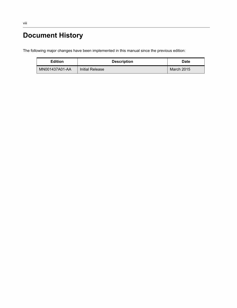
The following major changes have been implemented in this manual since the previous edition:
Edition Description Date
MN001437A01-AA Initial Release March 2015
Table of Contents ix
Table of Contents
Foreword.........................................................................................................ii
General Safety Precautions......................................................................................................................... iiComputer Software Copyrights ................................................................................................................... iiDocument Copyrights .................................................................................................................................. iiDisclaimer.................................................................................................................................................... iiTrademarks ................................................................................................................................................. ii
General Safety and Installation Standards and Guidelines............................................................................iii
MOTOTRBO SLR 5000 Series RepeaterSupplemental Safety and Installation Requirements.................................vi
Environmental Information..........................................................................vii
Document History ...................................................................................... viii
Chapter 1 SLR 5000 Series Repeater.................................................. 1-1
1.1 Notations Used in This Manual .................................................................................................... 1-11.2 Description................................................................................................................................... 1-11.3 Operating Features...................................................................................................................... 1-41.4 Frequency Ranges and Power Levels ......................................................................................... 1-51.5 Specifications............................................................................................................................... 1-61.6 Theory of Operation..................................................................................................................... 1-91.7 Basic Repeater Level Troubleshooting – RDAC and LEDs....................................................... 1-111.8 Repeater Model Numbering Scheme ........................................................................................ 1-141.9 Model Chart ............................................................................................................................... 1-15
1.9.1 VHF High Power .......................................................................................................... 1-151.9.2 UHF1 High Power ......................................................................................................... 1-15
Chapter 2 SLR 5000 Series Satellite Receiver ................................... 2-1
2.1 Description................................................................................................................................... 2-12.2 Operating Features...................................................................................................................... 2-12.3 Frequency Ranges ...................................................................................................................... 2-12.4 Specifications............................................................................................................................... 2-12.5 Configuration ............................................................................................................................... 2-22.6 Basic Station Level Troubleshooting – RDAC and LEDs ............................................................ 2-32.7 Model Chart ................................................................................................................................. 2-3

x Table of Contents
Chapter 3 SLR 5000 Series Modem..................................................... 3-1
3.1 Description ................................................................................................................................... 3-13.1.1 General Description ......................................................................................................... 3-13.1.2 Input and Output Connections ......................................................................................... 3-13.1.3 Frequency Bands............................................................................................................. 3-2
3.2 Receiver Subsystem .................................................................................................................... 3-23.2.1 Description....................................................................................................................... 3-23.2.2 Specifications................................................................................................................... 3-3
3.3 Transmitter Exciter Subsystem .................................................................................................... 3-33.3.1 Description....................................................................................................................... 3-33.3.2 Specifications................................................................................................................... 3-4
3.4 Station Control Subsystem .......................................................................................................... 3-43.4.1 Description....................................................................................................................... 3-43.4.2 High Stability Reference Block ........................................................................................ 3-53.4.3 Audio................................................................................................................................ 3-5
3.5 Station Control Interface .............................................................................................................. 3-63.5.1 Front Panel Interface Connector...................................................................................... 3-63.5.2 Rear Panel Connections.................................................................................................. 3-63.5.3 Power Amplifier Interface Connector ............................................................................... 3-63.5.4 Power Supply Interface Connector .................................................................................. 3-63.5.5 Expansion Board Interface Connector............................................................................. 3-73.5.6 Chassis ID Interface Connector....................................................................................... 3-7
Chapter 4 SLR 5000 Series Power Amplifier...................................... 4-1
4.1 Description ................................................................................................................................... 4-14.2 General Description ..................................................................................................................... 4-14.3 Input and Output Connections ..................................................................................................... 4-24.4 Frequency Ranges....................................................................................................................... 4-24.5 Specifications............................................................................................................................... 4-34.6 Modem Interface .......................................................................................................................... 4-3
Chapter 5 SLR 5000 Series Power Supply ......................................... 5-1
5.1 Description ................................................................................................................................... 5-15.1.1 General Description ......................................................................................................... 5-1
5.2 Specifications............................................................................................................................... 5-25.3 Power Supply Interface................................................................................................................ 5-3
5.3.1 Power Source Inputs ....................................................................................................... 5-35.3.2 Power Supply Outputs ..................................................................................................... 5-45.3.3 Power Supply Digital Interface......................................................................................... 5-45.3.4 Power Supply Output Cable Signaling............................................................................. 5-5
Chapter 6 SLR 5000 Series Front Panel ............................................. 6-1
6.1 Description ................................................................................................................................... 6-16.1.1 General Description ......................................................................................................... 6-1
6.2 Input and Output Connections ..................................................................................................... 6-16.3 Interfaces ..................................................................................................................................... 6-2
Table of Contents xi
6.3.1 Modem Interface.............................................................................................................. 6-26.3.2 User/ Service Interface .................................................................................................... 6-2
6.3.2.1 USB .................................................................................................................. 6-26.3.2.2 LED Indicators .................................................................................................. 6-2
Chapter 7 SLR 5000 Series Back Panel .............................................. 7-1
7.1 Description................................................................................................................................... 7-17.1.1 General Description......................................................................................................... 7-1
7.2 Back panel Interfaces .................................................................................................................. 7-27.2.1 AC Power Inlet................................................................................................................. 7-27.2.2 DC Power Inlet / DC Charger Outlet................................................................................ 7-27.2.3 Option 1/GNSS................................................................................................................ 7-37.2.4 Option 2/WLAN................................................................................................................ 7-37.2.5 USB ................................................................................................................................. 7-37.2.6 Ethernet 1 ........................................................................................................................ 7-47.2.7 Ethernet 2 ........................................................................................................................ 7-57.2.8 Auxiliary (Aux) ................................................................................................................. 7-67.2.9 Frequency Reference ...................................................................................................... 7-97.2.10 Receiver RF..................................................................................................................... 7-97.2.11 Transmitter RF............................................................................................................... 7-107.2.12 Bonding Ground Connection ......................................................................................... 7-10
Chapter 8 SLR 5000 Series Test Equipment And Service Aids........ 8-1
8.1 Recommended Test Equipment .................................................................................................. 8-18.2 Service Aids................................................................................................................................. 8-2
Chapter 9 SLR 5000 Series Performance Check or Testing ............. 9-1
9.1 General ........................................................................................................................................ 9-19.2 Transmitter Testing...................................................................................................................... 9-1
9.2.1 Introduction...................................................................................................................... 9-19.2.2 Test Equipment ............................................................................................................... 9-19.2.3 Verifying Transmitter Circuitry Procedure........................................................................ 9-2
9.3 Receiver Testing.......................................................................................................................... 9-49.3.1 Introduction...................................................................................................................... 9-49.3.2 Required Test Equipment................................................................................................ 9-49.3.3 Verifying Receiver Circuitry Procedure............................................................................ 9-5
Chapter 10 SLR 5000 Series Programming and Tuning ................... 10-1
10.1 Introduction ................................................................................................................................ 10-110.2 Customer Programming Software Setup ................................................................................... 10-110.3 Reference Oscillator Alignment ................................................................................................. 10-2
10.3.1 Tuning Procedure .......................................................................................................... 10-210.4 Repeater Tuning Setup.............................................................................................................. 10-310.5 Rx Audio Level Set .................................................................................................................... 10-4
10.5.1 Tuning Procedure .......................................................................................................... 10-4

xii Table of Contents
10.6 Tx Audio Level Set..................................................................................................................... 10-510.6.1 Tuning Procedure .......................................................................................................... 10-5
10.7 Modulation Limit Alignment........................................................................................................ 10-710.7.1 Tuning Procedure (with no Tx Data and no PL) ............................................................ 10-710.7.2 Verification (with no Tx Data and no PL) ....................................................................... 10-810.7.3 Tuning Procedure (with Tx Data or PL) ......................................................................... 10-910.7.4 Verification (with Tx Data or PL) .................................................................................. 10-10
Chapter 11 SLR 5000 Series Maintenance and Disassembly/Reassembly ....................................................................... 11-1
11.1 Introduction ................................................................................................................................ 11-111.2 Routine Maintenance ................................................................................................................. 11-111.3 Preventive Maintenance ............................................................................................................ 11-1
11.3.1 Inspection ...................................................................................................................... 11-111.3.2 Cleaning Procedures ..................................................................................................... 11-1
11.4 Safe Handling of CMOS and LDMOS Devices .......................................................................... 11-211.5 Disassembly............................................................................................................................... 11-4
11.5.1 Disassembly – General.................................................................................................. 11-411.5.2 Disassembly – Detailed ................................................................................................. 11-4
11.5.2.1 Protective Cover Disassembly........................................................................ 11-411.5.2.2 Front Housing Disassembly............................................................................ 11-411.5.2.3 Cable Disassembly ......................................................................................... 11-511.5.2.4 Fan Disassembly ............................................................................................ 11-611.5.2.5 Front Panel Disassembly................................................................................ 11-711.5.2.6 Power Supply Removal .................................................................................. 11-711.5.2.7 Modem Removal............................................................................................. 11-811.5.2.8 Power Amplifier Module Removal................................................................... 11-911.5.2.9 Back Panel Removal .................................................................................... 11-10
11.6 Assembly and Reassembly...................................................................................................... 11-1111.6.1 Assembly – Detailed .................................................................................................... 11-11
11.6.1.1 Back Panel Installation ................................................................................. 11-1111.6.1.2 Input Cable Installation ................................................................................. 11-1211.6.1.3 Power Amplifier Module Installation.............................................................. 11-1311.6.1.4 Modem Installation........................................................................................ 11-1411.6.1.5 Power Supply Installation ............................................................................. 11-1611.6.1.6 Fan Installation ............................................................................................. 11-1811.6.1.7 Front Panel Installation ................................................................................. 11-1811.6.1.8 Cable Installation .......................................................................................... 11-1911.6.1.9 Front Housing Installation ............................................................................. 11-2111.6.1.10Protective Cover Installation ......................................................................... 11-21
11.7 Exploded Mechanical View ...................................................................................................... 11-2211.8 Parts List .................................................................................................................................. 11-2311.9 Torque Charts .......................................................................................................................... 11-24
Chapter 12 SLR 5000 Series Installation ............................................ 12-1
12.1 Pre-Installation Considerations .................................................................................................. 12-112.1.1 Installation Overview...................................................................................................... 12-112.1.2 Site Environmental Conditions....................................................................................... 12-212.1.3 Equipment Ventilation.................................................................................................... 12-2

Table of Contents xiii
12.1.3.1 Mounting the SLR 5000 Series Repeater in a Cabinet................................... 12-212.1.3.2 Mounting the SLR 5000 Series Repeater in a Rack....................................... 12-3
12.1.4 AC and DC Input Power Requirements......................................................................... 12-312.1.4.1 AC Input Power Requirements ....................................................................... 12-312.1.4.2 DC Input Power Requirements....................................................................... 12-312.1.4.3 Ground Connection ........................................................................................ 12-312.1.4.4 Battery Connection ......................................................................................... 12-412.1.4.5 RF Antenna Connections ............................................................................... 12-412.1.4.6 System Cable Connections ............................................................................ 12-4
12.1.5 Equipment Mounting Methods....................................................................................... 12-412.1.5.1 Floor-Mounted Cabinet ................................................................................... 12-512.1.5.2 Modular Racks................................................................................................ 12-612.1.5.3 Desk Mount .................................................................................................... 12-6
12.1.6 Site Grounding and Lightning Protection....................................................................... 12-712.1.6.1 Electrical Ground ............................................................................................ 12-712.1.6.2 RF Ground...................................................................................................... 12-712.1.6.3 Lightning Ground ............................................................................................ 12-712.1.6.4 Equipment Grounding..................................................................................... 12-7
12.1.7 Recommended Tools and Equipment ........................................................................... 12-712.1.8 Equipment Unpacking and Inspection ........................................................................... 12-8
12.1.8.1 Unpacking Equipment .................................................................................... 12-812.1.8.2 Initial Inspection.............................................................................................. 12-8
12.2 Mechanical Installation .............................................................................................................. 12-912.2.1 Equipment Unpacking and Inspection ........................................................................... 12-912.2.2 Mounting Procedures .................................................................................................... 12-9
12.2.2.1 Transferring Equipment from Shipping Container to Rack or Cabinet ........... 12-912.2.2.2 Installing Racks ............................................................................................ 12-1012.2.2.3 Installing Cabinets ........................................................................................ 12-1112.2.2.4 Desk Mount .................................................................................................. 12-11
12.3 Electrical Connections ............................................................................................................. 12-1212.3.1 Power Supply Connections ......................................................................................... 12-13
12.3.1.1 AC Input Power Connection ......................................................................... 12-1312.3.1.2 DC Input Power Connection/ DC Charger Connection................................. 12-1312.3.1.3 Ground Connection ...................................................................................... 12-1312.3.1.4 Battery Connection ....................................................................................... 12-1412.3.1.5 RF Antenna Connections ............................................................................. 12-1412.3.1.6 System Cable Connections .......................................................................... 12-14
12.4 Post Installation Checklist ........................................................................................................ 12-1412.4.1 Applying Power............................................................................................................ 12-1412.4.2 Verifying Proper Operation .......................................................................................... 12-1512.4.3 Front Panel LEDs ........................................................................................................ 12-1512.4.4 Copying the Repeater Codeplug Data to a Computer................................................. 12-15
12.5 Installing Repeater Hardware Options..................................................................................... 12-1512.5.1 General Bonding and Grounding Requirements ......................................................... 12-1512.5.2 General Cabling Requirements ................................................................................... 12-15
Appendix A Accessories .........................................................................A-1
A.1 Introduction ..................................................................................................................................A-1A.1.1 Cables .............................................................................................................................A-1A.1.2 Documentation ................................................................................................................A-1A.1.3 Mounting..........................................................................................................................A-1A.1.4 Service Parts ...................................................................................................................A-2

xiv Table of Contents
A.1.5 Service Tools ...................................................................................................................A-2
Appendix B EMEA Regional Warranty, Service and Technical Support...............................................................B-1
B.1 Warranty and Service Support .....................................................................................................B-1B.1.1 Warranty Period and Return Instructions.........................................................................B-1B.1.2 After Warranty Period ......................................................................................................B-1
B.2 European Radio Support Centre (ERSC) ....................................................................................B-1B.3 Piece Parts...................................................................................................................................B-2B.4 Technical Support ........................................................................................................................B-2B.5 Further Assistance From Motorola...............................................................................................B-2
Appendix C SLR 5000 Series Third Party Controllers ..........................C-1
C.1 Overview ..................................................................................................................................... C-1C.2 Community Repeater Panel ........................................................................................................ C-2
C.2.1 Description...................................................................................................................... C-2C.2.2 Compatibility ................................................................................................................... C-2C.2.3 Hardware Connections ................................................................................................... C-3C.2.4 CPS Configuration .......................................................................................................... C-4C.2.5 Community Repeater Panel Settings.............................................................................. C-5
C.2.5.1 Discriminator.................................................................................................... C-5C.2.5.2 Tx Audio........................................................................................................... C-5C.2.5.3 Continuous Tone-Controlled Squelch Systems (CTCSS) Out......................... C-5C.2.5.4 Tx Audio Pre-Emphasis ................................................................................... C-6C.2.5.5 Carrier Operated Relay (COR) ........................................................................ C-6
C.3 Phone Patch ............................................................................................................................... C-6C.3.1 Description...................................................................................................................... C-6C.3.2 Compatibility ................................................................................................................... C-6C.3.3 Hardware Connections ................................................................................................... C-7C.3.4 CPS Configuration .......................................................................................................... C-8C.3.5 Phone Patch Level Settings............................................................................................ C-9
C.3.5.1 Disc.................................................................................................................. C-9C.3.5.2 Tx Audio........................................................................................................... C-9C.3.5.3 CTCSS/ DCS DECODE INPUT/ COR............................................................. C-9
C.4 Tone Remote Adapter............................................................................................................... C-10C.4.1 Description.................................................................................................................... C-10C.4.2 Compatibility ................................................................................................................. C-10C.4.3 Hardware Connections ................................................................................................. C-11C.4.4 CPS Configuration (For a 15 Channel Remote Control)............................................... C-12C.4.5 Tone Remote Adapter settings ..................................................................................... C-14
C.4.5.1 Radio Rx ........................................................................................................ C-14C.4.5.2 Radio Tx ........................................................................................................ C-14C.4.5.3 Channel Steering ........................................................................................... C-14C.4.5.4 Monitoring ...................................................................................................... C-14C.4.5.5 PTT ................................................................................................................ C-14C.4.5.6 Wildcard 1 (optional) ...................................................................................... C-14
C.5 Trunking Controllers.................................................................................................................. C-15C.5.1 Description.................................................................................................................... C-15C.5.2 Compatibility ................................................................................................................. C-16C.5.3 Hardware Connections ................................................................................................. C-16
Table of Contents xv
C.5.4 CPS Configuration.........................................................................................................C-18C.5.5 Trunking Controller Settings ..........................................................................................C-19
C.5.5.1 Discriminator...................................................................................................C-19C.5.5.2 Tx Audio .........................................................................................................C-19C.5.5.3 Tx Data ...........................................................................................................C-19
Appendix D Audio Enhancement ...........................................................D-1
D.1 Overview......................................................................................................................................D-1D.1.1 Hear Clear feature with the third party controllers ...........................................................D-1D.1.2 Third party controller and the subscriber configuration for Hear Clear feature................D-1D.1.3 Hear Clear feature configuration in repeater mode .........................................................D-2D.1.4 Companding feature configuration between third party controllers and subscriber.........D-2D.1.5 Companding feature configuration between the repeater and subscribers .....................D-2
Appendix E MOTOTRBO Repeater – EME ASSESSMENT ...................E-1
E.1 Executive Summary.....................................................................................................................E-1E.2 Exposure Prediction Model ..........................................................................................................E-1
E.2.1 Exposure in Front of the Antenna....................................................................................E-1E.2.2 Exposure at Ground Level...............................................................................................E-3
E.3 Typical System Configuration ......................................................................................................E-4E.4 Exposure Limits ...........................................................................................................................E-4E.5 EME Exposure Evaluation ...........................................................................................................E-4
E.5.1 Exposure in Front of the Antenna....................................................................................E-4E.5.2 Exposure at Ground Level...............................................................................................E-4
E.6 Compliance Boundary Description ..............................................................................................E-5E.7 Product Put In Service .................................................................................................................E-5E.8 References ..................................................................................................................................E-6
Glossary of Terms and Acronyms...............................................Glossary-1

xvi List of Figures
List of Figures
Figure 1-1 Front view of the SLR 5000 Series Repeater....................................................................... 1-2Figure 1-2 Rear view of the SLR 5000 Series Repeater ....................................................................... 1-3Figure 1-3 Front view (without top cover) of the SLR 5000 Series Repeater ........................................ 1-3Figure 1-4 Front view (without top and bottom covers and front panel) of the
SLR 5000 Series Repeater .................................................................................................. 1-3Figure 1-5 RDAC Diagnostic Screen................................................................................................... 1-11Figure 1-6 Repeater Model Numbering Scheme................................................................................. 1-14Figure 2-1 “Operation Mode” configuration for Satellite Receiver Functionality .................................... 2-2Figure 3-1 Modem Module Connector Locations .................................................................................. 3-1Figure 3-2 High Stability Reference Circuit............................................................................................ 3-5Figure 3-3 Audio Block Diagram............................................................................................................ 3-5Figure 3-4 Power Amplifier Interface Connector Pin Locations............................................................. 3-6Figure 3-5 Power Supply Interface Connector Pin Locations................................................................ 3-6Figure 3-6 Expansion Board Interface Connector Pin Locations........................................................... 3-7Figure 3-7 Chassis ID Interface Connector Pin Locations..................................................................... 3-7Figure 4-1 Input and Output Connections ............................................................................................. 4-2Figure 4-2 Modem Interface Connector Pin Locations .......................................................................... 4-3Figure 5-1 Front and Rear Views of the SLR 5000 Series Power Supply ............................................. 5-2Figure 5-2 Power Source Inputs ............................................................................................................ 5-3Figure 5-3 Power Supply Outputs.......................................................................................................... 5-4Figure 5-4 Power Supply Digital Interface ............................................................................................. 5-4Figure 6-1 Front Panel Input and Output Connections.......................................................................... 6-1Figure 7-1 Back Panel Connector Names and Locations...................................................................... 7-1Figure 7-2 AC Power Inlet Connector and Repeater Power Switch ...................................................... 7-2Figure 7-3 DC Power Inlet/ DC Charger Outlet Connector.................................................................... 7-2Figure 7-4 Option 1/GNSS Connector ................................................................................................... 7-3Figure 7-5 Option 2/WLAN Connector................................................................................................... 7-3Figure 7-6 USB Connector .................................................................................................................... 7-3Figure 7-7 Ethernet 1 Connector ........................................................................................................... 7-4Figure 7-8 Ethernet 2 Connector ........................................................................................................... 7-5Figure 7-9 Auxiliary Connector .............................................................................................................. 7-6Figure 7-10 Frequency Reference Connector ......................................................................................... 7-9Figure 7-11 Receiver RF Connector........................................................................................................ 7-9Figure 7-12 Transmitter RF Connector.................................................................................................. 7-10Figure 7-13 Bonding Ground Connection.............................................................................................. 7-10Figure 9-1 Test Equipment Setup for Verifying Transmitter Circuitry..................................................... 9-3Figure 9-2 Test Equipment Setup for Verifying Receiver Circuitry......................................................... 9-6Figure 10-1 Customer Programming Software Setup............................................................................ 10-1Figure 10-2 Front view of SLR 5000 Series Repeater........................................................................... 10-2Figure 10-3 Rear view of SLR 5000 Series Repeater ........................................................................... 10-2Figure 10-4 Tx Menu Tree (Ref. Oscillator) ........................................................................................... 10-3Figure 10-5 SLR 5000 Series Repeater Tuning Equipment Setup........................................................ 10-3Figure 10-6 Rx Menu tree (Rx Rated Volume) ......................................................................................10-4Figure 10-7 Auxiliary Connector ............................................................................................................ 10-5Figure 10-8 Tx Menu Tree (Tx Audio Level).......................................................................................... 10-6Figure 10-9 Tx Menu tree (Tuning Procedure with no Tx data) ............................................................. 10-7Figure 10-10 Example of maximum deviation limit calculation................................................................ 10-9Figure 11-1 Removing Front Housing from Repeater ........................................................................... 11-5Figure 11-2 Removing Cables............................................................................................................... 11-6Figure 11-3 Removing Fan.................................................................................................................... 11-6
List of Figures xvii
Figure 11-4 Removing Front Panel ....................................................................................................... 11-7Figure 11-5 Removing Power Supply Module from Repeater ............................................................... 11-7Figure 11-6 Removing Modem.............................................................................................................. 11-8Figure 11-7 Removing Power Amplifier Module .................................................................................... 11-9Figure 11-8 Removing Rx and REF BNC Cables................................................................................ 11-10Figure 11-9 Removing Ground Screw................................................................................................. 11-10Figure 11-10 Installing M3 Screws .........................................................................................................11-11Figure 11-11 Installing M6 Screw ...........................................................................................................11-11Figure 11-12 Installing Rx and Reference Cables................................................................................. 11-12Figure 11-13 Assembling Lock Washers onto Connectors ................................................................... 11-12Figure 11-14 Installing WLAN and GNSS Rubber Plugs....................................................................... 11-13Figure 11-15 Installing Power Amplifier Module into Repeater ............................................................. 11-13Figure 11-16 Securing Power Amplifier Module to Repeater Chassis .................................................. 11-14Figure 11-17 Securing Modem to Repeater Frame............................................................................... 11-14Figure 11-18 Securing Rx and Reference Cable Connectors ............................................................... 11-15Figure 11-19 Modem FRU Product Label.............................................................................................. 11-15Figure 11-20 Installing Power Supply Module ....................................................................................... 11-16Figure 11-21 Installing M4 Screws ........................................................................................................ 11-16Figure 11-22 Snapping Fan Cable ........................................................................................................ 11-17Figure 11-23 Installing Fan.................................................................................................................... 11-18Figure 11-24 Installing Front Panel ....................................................................................................... 11-18Figure 11-25 Installing Power Screws ................................................................................................... 11-19Figure 11-26 Securing Cables............................................................................................................... 11-20Figure 11-27 Securing Front Housing ................................................................................................... 11-21Figure 11-28 Installing M3 Screws ........................................................................................................ 11-21Figure 11-29 SLR 5000 Series Assembly Exploded View..................................................................... 11-22Figure 12-1 Floor Mount Cabinet .......................................................................................................... 12-5Figure 12-2 Modular Rack..................................................................................................................... 12-6Figure 12-3 Desk Mount Installation.................................................................................................... 12-11Figure 12-4 Back Panel Connector Names and Locations.................................................................. 12-12Figure 12-5 Location of USB Connector ............................................................................................. 12-13Figure C-1 CPS Settings to Configure SLR 5000 Series Repeater for Analog Mode............................C-2Figure C-2 Model Zetron 38 Repeater Panel .........................................................................................C-2Figure C-3 Signal Connections between SLR 5000 Series Repeater and
Community Repeater Panel .................................................................................................C-3Figure C-4 CPS Configuration for Community Repeater Panel (1 of 2).................................................C-4Figure C-5 CPS Configuration for Community Repeater Panel (2 of 2).................................................C-5Figure C-6 Zetron Model 30 Phone Patch .............................................................................................C-6Figure C-7 Signal Connections between SLR 5000 Series Repeater and Zetron Model 30
Phone Patch (Analog Phone Patch Cable & Digital Phone Patch Cable)............................C-7Figure C-8 CPS Configuration for Phone Patch (1 of 2) ........................................................................C-8Figure C-9 CPS Configuration for Phone Patch (2 of 2) ........................................................................C-9Figure C-10 Model L3276 Tone Remote Adapter ..................................................................................C-10Figure C-11 Signal Connections between SLR 5000 Series Repeater and
Motorola L3276 25-Pin connector for a 15 Channel Remote Control ................................C-11Figure C-12 CPS Configuration for L3276 Tone Remote Adapter
(For a 15 Channel Remote Control)...................................................................................C-13Figure C-13 Model Trident’s Marauder ..................................................................................................C-15Figure C-14 Model Trident’s Raider .......................................................................................................C-15Figure C-15 Model Trident’s NTS ..........................................................................................................C-16Figure C-16 Signal connections between SLR 5000 Series Repeater, Trident Model Raider,
Marauder and NTS ............................................................................................................C-17Figure C-17 CPS Configuration for Trident Model Raider, Marauder and NTS .....................................C-18

xviii List of Figures
Figure E-1 Reference frame for the point of interest (POI) cylindrical co-ordinates...............................E-2Figure E-2 Schematic of the ground-level exposure model adopted for the assessment......................E-3Figure E-3 Compliance boundary for general public (GP) and occupational (OCC) exposure..............E-5

List of Tables xix
List of Tables
Table 1-1 SLR 5000 Series Frequency Ranges and Power Levels ..................................................... 1-5Table 1-2 SLR 5000 Series Repeater General Specifications (All Bands)........................................... 1-6Table 1-3 SLR 5000 Series Repeater Specifications ........................................................................... 1-7Table 1-4 Front Panel LED indicators ................................................................................................ 1-12Table 1-5 SLR 5000 Series Front Panel LED Definitions................................................................... 1-12Table 3-1 Specifications of Receiver Subsystem ................................................................................. 3-3Table 3-2 Specifications of Transmitter Exciter Subsystem ................................................................. 3-4Table 4-1 Specifications of Power Amplifier ......................................................................................... 4-3Table 5-1 Power Supply AC Performance Specifications .................................................................... 5-2Table 5-2 Power Supply DC Performance Specifications .................................................................... 5-3Table 5-3 Power Supply Battery Charger Performance Specifications................................................ 5-3Table 5-1 Power Supply Output Cable SIgnalling................................................................................ 5-5Table 7-1 Connector Type and Primary Function................................................................................. 7-1Table 7-2 AC Power Inlet Connector ................................................................................................... 7-2Table 7-3 DC Power Inlet/ DC Charger Outlet Connector.................................................................... 7-2Table 7-4 USB Connector .................................................................................................................... 7-3Table 7-5 Ethernet 1 Connector ........................................................................................................... 7-4Table 7-6 Ethernet 2 Connector ........................................................................................................... 7-5Table 7-7 Auxiliary Connector .............................................................................................................. 7-6Table 7-8 Frequency Reference .......................................................................................................... 7-9Table 8-1 Recommended Test Equipment ........................................................................................... 8-1Table 11-1 SLR 5000 Series Exploded View Parts List ..................................................................... 11-23Table 11-2 Torque Specifications for Nuts and Screws...................................................................... 11-24Table 12-1 Cabinet Models .................................................................................................................. 12-5Table 12-2 Cabinet Slide...................................................................................................................... 12-5Table 12-3 Rack Models ...................................................................................................................... 12-6Table 12-4 Connector Type and Primary Function............................................................................. 12-12Table E-1 EME Compliance Distances Based on Example UHF Evaluation .......................................E-1

xx List of Tables
Related Publications
MOTOTRBO SLR 5000 Series Quick Start Guide.............................................................. MN001442A01

Summary of Bands Available xxi
Summary of Bands Available
Table below lists the SLR 5000 Series Repeater bands available in this manual. For details, see Model Charts section.
Frequency Band Bandwidth Power Level
VHF 136 – 174 MHz 1–50 W
UHF 400 – 470 MHz 1–50 W

xxii Summary of Bands Available
Notes
Chapter 1 SLR 5000 Series Repeater
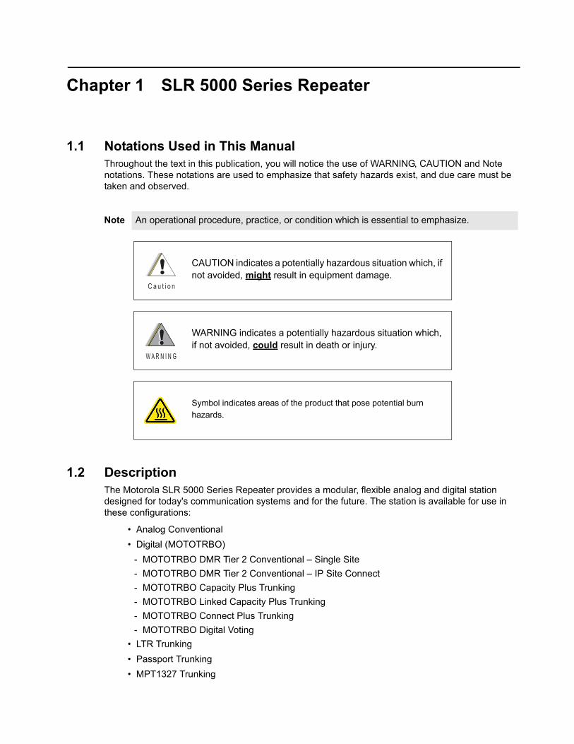
1.1 Notations Used in This ManualThroughout the text in this publication, you will notice the use of WARNING, CAUTION and Note notations. These notations are used to emphasize that safety hazards exist, and due care must be taken and observed.
1.2 DescriptionThe Motorola SLR 5000 Series Repeater provides a modular, flexible analog and digital station designed for today's communication systems and for the future. The station is available for use in these configurations:
• Analog Conventional
• Digital (MOTOTRBO)
- MOTOTRBO DMR Tier 2 Conventional – Single Site
- MOTOTRBO DMR Tier 2 Conventional – IP Site Connect
- MOTOTRBO Capacity Plus Trunking
- MOTOTRBO Linked Capacity Plus Trunking
- MOTOTRBO Connect Plus Trunking
- MOTOTRBO Digital Voting
• LTR Trunking
• Passport Trunking
• MPT1327 Trunking
Note An operational procedure, practice, or condition which is essential to emphasize.
CAUTION indicates a potentially hazardous situation which, if not avoided, might result in equipment damage.
WARNING indicates a potentially hazardous situation which, if not avoided, could result in death or injury.
Symbol indicates areas of the product that pose potential burn
hazards.
C a u t i o n
W A R N I N G

1-2 SLR 5000 Series Repeater: Description
The SLR 5000 series can either be configured as a stand-alone repeater or as a repeater connected to a back-end network, as in the case of operating in IP Site Connect mode. As a repeater, it listens on one uplink frequency, and then re-transmits on a downlink frequency, thus providing the RF interface to the field subscribers. When configured for analog station operation, the repeater is designed to operate with most existing analog systems, which enables a smooth migration to the MOTOTRBO system.
When configured for digital operation, the repeater offers additional services. The digital repeater operates in TDMA mode, which essentially divides one channel into two virtual channels using time slots; therefore the user capacity is doubled. The repeater utilizes embedded signaling to inform the field radios of the busy/idle status of each channel (time slot), the type of traffic, and even the source and destination information.
The SLR 5000 series facilitates the field replaceable unit (FRU) concept of field repair to maximize system uptime. The FRU concept also aids in allowing the end user/ maintainer to lower their inventory costs. The base model SLR 5000 series FRUs are as follows:
- Modem FRU
- Power Amplifier FRU
- Power Supply FRU
- Front Panel FRU
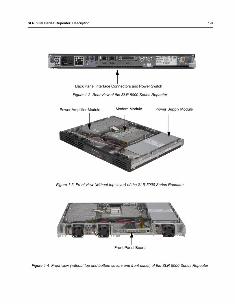
See Figure 1-1 for the front view and Figure 1-2 for the rear view of SLR 5000 series repeater. Figure 1-3 shows the front view portion of the repeater without the top cover and Figure 1-4 shows the front view portion of the repeater without the top cover, bottom cover, and front panel.
Figure 1-1 Front view of the SLR 5000 Series Repeater
Note Certain software features enabled via the CPS can be configured with the Online Help orwith a regional representative. Refer to the regional Ordering Guide to determine thefeatures available within the respective regions.
Front Panel LED Indicators USB Port
SLR 5000 Series Repeater: Description 1-3
Figure 1-2 Rear view of the SLR 5000 Series Repeater
Figure 1-3 Front view (without top cover) of the SLR 5000 Series Repeater
Figure 1-4 Front view (without top and bottom covers and front panel) of the SLR 5000 Series Repeater
Back Panel Interface Connectors and Power Switch
Power Amplifier Module Modem Module Power Supply Module
Front Panel Board

1-4 SLR 5000 Series Repeater: Operating Features
1.3 Operating FeaturesThe following are the standard features of an SLR 5000 series model:
• MOTOTRBO Conventional Operation (2-Slot TDMA, 4FSK Modulation)
• Analog Conventional Operation (FM)
• Continuous Duty Cycle Operation over -30 °C to +60 °C
• Meets or exceeds the following standards:
- TIA603D
- ETSI 086
- ETSI 113
- ETSI TS 102 361-1 Part 1: DMR Air Interface Protocol
- ETSI TS 102 361-2 Part 2: DMR Voice and Generic Services and Facilities
- ETSI TS 102 361-3 Part 3: DMR Packet Data Protocol
• AMBE +2™ Digital VOCODER
• Synthesized Frequency Generation
• Female N-type Antenna Connector (Tx)
• Female BNC Antenna Connector (Rx)
• Ethernet Port (Network)
• Front mounted USB Port (Service)
• 12 configurable GPIO ports (Digital)
• 4 configurable GPI ports (Analog)
• 2 configurable GPO ports (Analog)
• Power for third party controllers (1 Amp)
• 1.5 PPM Frequency Stability (Temperature AND 1-Year Aging) (VHF and UHF)
• External Reference Capability
• Switching Power Supply operates from 85 – 264 VAC (47 – 63 Hz)
• Multi-Power Source configurable (AC, DC, or AC with Battery Revert)
• Integrated 3 A battery charger
• Station Diagnostic Tests – Fixed Set of Tests run upon Start-up
• Physical Dimensions: 1.75" H x 19" W x 14.6" D (44 x 483 x 370 mm) 1RU
• Weight: 19 pounds (8.62 kg) excluding cabinet or other peripheral equipment
Motorola Network Interface:
• IP Site Connect
• Repeater Diagnostics and Control (RDAC)
• Linked Capacity Plus
• Connect Plus
Third Party Controller Interface:
• Phone Patch
• Multi Coded Squelch Interface (Repeater Panel)
• Tone Remote Adapter
• LTR Trunking
SLR 5000 Series Repeater: Frequency Ranges and Power Levels 1-5
• Passport Trunking
• MPT1327 Trunking
In addition, the following features are also included. These features are shipped in a preset condition, but may be altered through the use of the CPS.
• 64 Tx/Rx Frequencies – Factory Programmed with 1 Tx, 1 Rx
• 12.5 kHz or 25 kHz Operation – Factory Programmed to 12.5 kHz
• 1 Tx and 1 Rx (PL or DPL) Squelch Code per channel – Factory Programmed to CSQ
• Base Station Identification (BSI) – Factory Programmed as “BLANK” (“BLANK” disables BSI)
• Push-To-Talk (PTT) Priority – Factory Programmed to Repeat Path
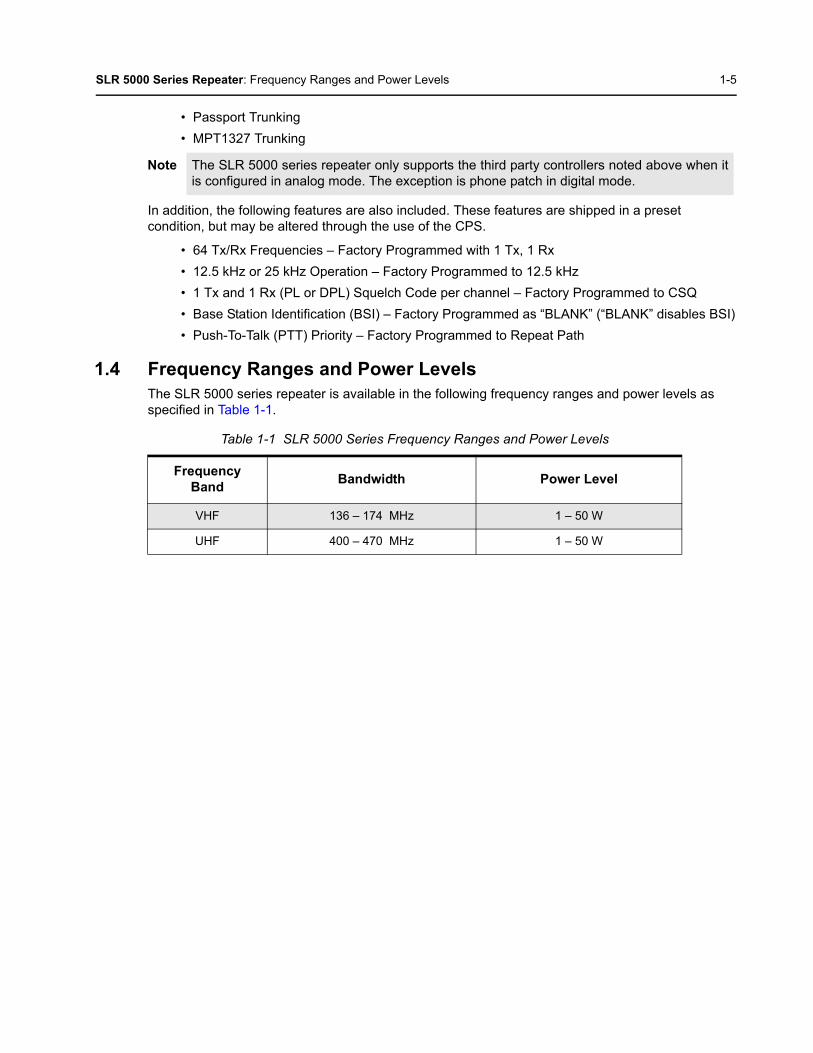
1.4 Frequency Ranges and Power LevelsThe SLR 5000 series repeater is available in the following frequency ranges and power levels as specified in Table 1-1.
Note The SLR 5000 series repeater only supports the third party controllers noted above when itis configured in analog mode. The exception is phone patch in digital mode.
Table 1-1 SLR 5000 Series Frequency Ranges and Power Levels
Frequency Band
Bandwidth Power Level
VHF 136 – 174 MHz 1 – 50 W
UHF 400 – 470 MHz 1 – 50 W
1-6 SLR 5000 Series Repeater: Specifications
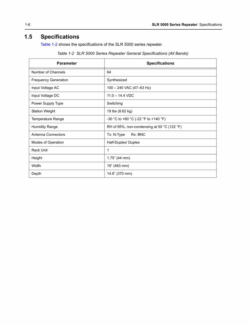
1.5 SpecificationsTable 1-2 shows the specifications of the SLR 5000 series repeater.
Table 1-2 SLR 5000 Series Repeater General Specifications (All Bands)
Parameter Specifications
Number of Channels 64
Frequency Generation Synthesized
Input Voltage AC 100 – 240 VAC (47–63 Hz)
Input Voltage DC 11.0 – 14.4 VDC
Power Supply Type Switching
Station Weight 19 lbs (8.62 kg)
Temperature Range -30 °C to +60 °C (-22 °F to +140 °F)
Humidity Range RH of 95%, non-condensing at 50 °C (122 °F)
Antenna Connectors Tx: N-Type Rx: BNC
Modes of Operation Half-Duplex/ Duplex
Rack Unit 1
Height 1.75” (44 mm)
Width 19” (483 mm)
Depth 14.6” (370 mm)

SLR 5000 Series Repeater: Specifications 1-7
Table 1-3 SLR 5000 Series Repeater Specifications
ParameterSpecifications
VHF UHF
Input Power (All Modulations) *
Standby (AC Line 117 V / 220 V) 0.18 A/ 0.25 A
50 W Transmit at Rated Power (AC Line 117 V / 220 V)
1.5 A/ 0.9 A
Standby (13.6 VDC) 0.73 A
50 W Transmit at Rated Power (13.6 VDC) 9.5 A
Frequency Reference
Internal Frequency Stability (PPM) 0.5 PPM (temperature)
External Reference Capable Yes
Frequency Bands
Electronic Bandwidth 136 – 174 MHz 400 – 470 MHz
Receiver
Selectivity 25 kHz / 12.5 kHz (TIA603D) 80 dB/ 50 dB 75 dB/ 50 dB
Selectivity 25 kHz / 12.5 kHz (TIA603) 80 dB/ 65 dB 75 dB/ 65 dB
Selectivity 25 kHz / 12.5 kHz (ETSI) 70 dB/ 63 dB
Sensitivity (12 dB SINAD) 0.3 uV
Sensitivity (5% BER) 0.3 uV
Intermodulation Rejection (TIA603D) 80 dB
Intermodulation Rejection (ETSI) 70 dB
Spurious Rejection (TIA603D) 85 dB
Spurious Rejection (ETSI) 75 dB
Conducted Spurious Emissions -57 dBm
Audio Distortion <3%
Audio Response Per TIA/ ETSI
FM Hum and Noise 25 kHz / 12.5 kHz -50 dB/ -45 dB
Transmitter
Rated Output Power (Continuous Duty) 1 – 50 W
Intermodulation Attenuation 40 dB
Adjacent Channel Power 25 kHz / 12.5 kHz 75 dB / 60 dB
Modulation Fidelity (4FSK) FSK Error 5%FSK Magnitude 1%
1-8 SLR 5000 Series Repeater: Specifications
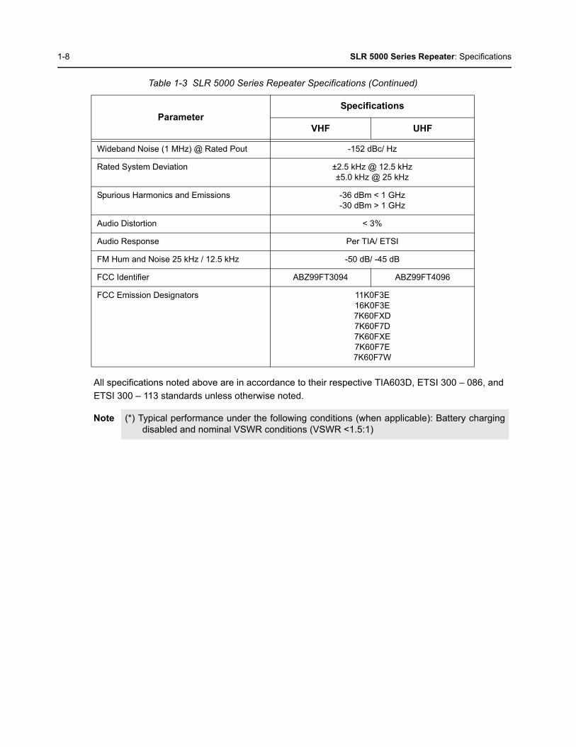
All specifications noted above are in accordance to their respective TIA603D, ETSI 300 – 086, and
ETSI 300 – 113 standards unless otherwise noted.
Wideband Noise (1 MHz) @ Rated Pout -152 dBc/ Hz
Rated System Deviation ±2.5 kHz @ 12.5 kHz±5.0 kHz @ 25 kHz
Spurious Harmonics and Emissions -36 dBm < 1 GHz-30 dBm > 1 GHz
Audio Distortion < 3%
Audio Response Per TIA/ ETSI
FM Hum and Noise 25 kHz / 12.5 kHz -50 dB/ -45 dB
FCC Identifier ABZ99FT3094 ABZ99FT4096
FCC Emission Designators 11K0F3E16K0F3E7K60FXD7K60F7D7K60FXE7K60F7E7K60F7W
Note (*) Typical performance under the following conditions (when applicable): Battery chargingdisabled and nominal VSWR conditions (VSWR <1.5:1)
Table 1-3 SLR 5000 Series Repeater Specifications (Continued)
ParameterSpecifications
VHF UHF

SLR 5000 Series Repeater: Theory of Operation 1-9
1.6 Theory of OperationThe SLR 5000 series repeater provides the radio frequency (RF) link between the repeater and the subscriber radios. The repeater acquires inbound signals via its external receive (Rx) antenna and then amplifies, filters and demodulates the signals into data or voice packets. From that point, the data is either forwarded to the repeater’s transmitter to subscriber radios, and/or the data is delivered via a wired interface for distribution to networked repeaters, consoles, or other networked infrastructure.
The SLR 5000 series repeater consists of a Modem, Power Amplifier (PA), Front Panel and Power Supply (PS). These modules are also known as field replaceable units (FRU).
• The Modem module is comprised of three subsystems, which are the Receiver subsystem, Exciter subsystem, and Station Control subsystem. At a high level, these subsystems are further explained below:
a. The Receiver subsystem is a dual heterodyne Receiver which receives the RF signal from the subscriber’s transmitter. It then converts the resulting final intermediate frequency (IF) from an analog signal to that of a digital word in IQ signal format. Finally, the Receiver delivers the IQ signal, via the SSI bus, to the Station Control subsystem for demodulation. Additionally, the Receiver subsystem also provides for its own metering and diagnostics via software, as well as self-contained calibration (no field tuning is needed for the Receiver subsystem).
b. The Exciter subsystem converts a two-port base band data signal, sent over the SSI bus from the Station Control subsystem, to an analog signal representation. The analog signal is then modulated with a low power RF transmitter carrier that is generated by the Exciter subsystem. The power modulated RF carrier is then amplified and delivered to the PA at an intermediate level of approximately +36 dBm for further amplification. The Exciter subsystem and PA constitute the transmitter of the SLR 5000 series repeater. Additionally, the Exciter subsystem also provides its own metering and diagnostics via software, as well as a self-contained calibration (no field tuning is needed for the Exciter subsystem).
c. The heart of the Station Control subsystem is the Texas Instruments DM8148 Host/ DSP processor. In general, the SCM controls the entire coordination of the repeater functions. Specifically, the Station Control subsystem provides for the following functionalities:
• Contains and runs the preloaded repeater software
• Manages inbound and outbound RF and Audio traffic
• Provides an on-board USB port for local configuring, alignment and diagnostics via the following applications:
- Customer Programming Software (CPS)
- Tuner application
- Repeater Diagnostic and Control (RDAC) software
• Provides an Ethernet port for IP site connectivity and remote RDAC
• Provides GPIO connectivity for third party controller interfaces
• Provides for analog repeater audio connectivity
• Data and Control to the Receiver subsystem via the SPI and SSI respectively
• Data and Control to the Exciter subsystem via the SPI and SSI respectively
• Control of the PA’s set power via the SPI
• Configuration and fault management of all subsystems including the PS and PA
• Generates the internal station reference
• Provides control of the front panel module’s indicator LEDs.
1-10 SLR 5000 Series Repeater: Theory of Operation
d. The PA module amplifies the intermediate level modulated RF signal from the Modem. It then delivers the amplified signal to the transmitter antenna port at a power level within the rated power band of the repeater, for transmission to the subscriber radios. In addition to its primary task of amplification, the PA provides the following hardware functions for the repeater.
• Harmonic attenuation
• Inter-modulation attenuation (IMA) suppression
• VSWR detection
• RF power control (primary means)
• Meters for diagnostics
• Power rollback for temperature, VSWR, and voltage
• Self-Contained calibration (no field alignment is needed for PA).
e. The Front Panel module provides LED indications for general assessment of the status and operational condition of the repeater. Additionally, the front panel also provides a USB service port for configuration and alignment of the repeater.
f. The PS Module provides DC power to the Modem, PA and Front Panel. It can also be used to provide auxiliary power (nominal 13.6 VDC) to a number of third party controllers. Additionally, it can operate in three different input modes:
• AC Input Only
• DC Input Only
• AC with Battery Revert.
In addition to providing power to the noted FRU and controllers, the PS also provides the following:
• AC Failure detect signaling to the Modem
• Output over-current protection
• Integrated 2 stage 3 amp battery charger.
• Further details can be found in the individual sections of the respective FRU chapters of this manual.
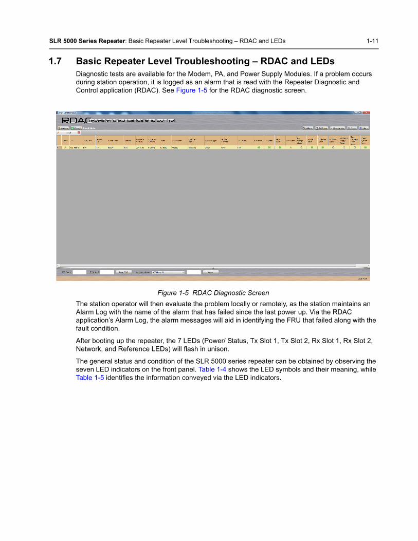
SLR 5000 Series Repeater: Basic Repeater Level Troubleshooting – RDAC and LEDs 1-11
1.7 Basic Repeater Level Troubleshooting – RDAC and LEDsDiagnostic tests are available for the Modem, PA, and Power Supply Modules. If a problem occurs during station operation, it is logged as an alarm that is read with the Repeater Diagnostic and Control application (RDAC). See Figure 1-5 for the RDAC diagnostic screen.
Figure 1-5 RDAC Diagnostic Screen
The station operator will then evaluate the problem locally or remotely, as the station maintains an Alarm Log with the name of the alarm that has failed since the last power up. Via the RDAC application’s Alarm Log, the alarm messages will aid in identifying the FRU that failed along with the fault condition.
After booting up the repeater, the 7 LEDs (Power/ Status, Tx Slot 1, Tx Slot 2, Rx Slot 1, Rx Slot 2, Network, and Reference LEDs) will flash in unison.
The general status and condition of the SLR 5000 series repeater can be obtained by observing the seven LED indicators on the front panel. Table 1-4 shows the LED symbols and their meaning, while Table 1-5 identifies the information conveyed via the LED indicators.

1-12 SLR 5000 Series Repeater: Basic Repeater Level Troubleshooting – RDAC and LEDs
Table 1-4 Front Panel LED indicators
LED Definition
Status
Tx A Tx Slot 1
Rx A Rx Slot 1
Tx B Tx Slot 2
Rx B Rx Slot 2
Ethernet Link/ Network Connectivity
Reference
Table 1-5 SLR 5000 Series Front Panel LED Definitions
LED Function Name LED Color LED State Status Indication
Power/Status Off Off Off
Green Flashing Operating Normally, with DC power
Solid Operating Normally, with AC power
Red Flashing Repeater is Disabled (by customer)
Solid Not Operational – Major Alarm
Amber Flashing Check Alarm Log– Alarm occurred and cleared butremains latched (configurable)
Solid Repeater Operational – Minor Alarm
Tx A Off Off Transmitter is not transmitting
Green Solid Tx slot A or Analog (at desired power)
Amber* Solid Tx slot A or Analog (at less than desired power)
Red* Solid Tx Fail
Flashing Tx Inhibit
Rx A Off Off No receive carrier detected
Green Solid Rx Slot A or Analog (qualifier met)
Amber* Solid Rx Slot A or Analog (non-qualified)
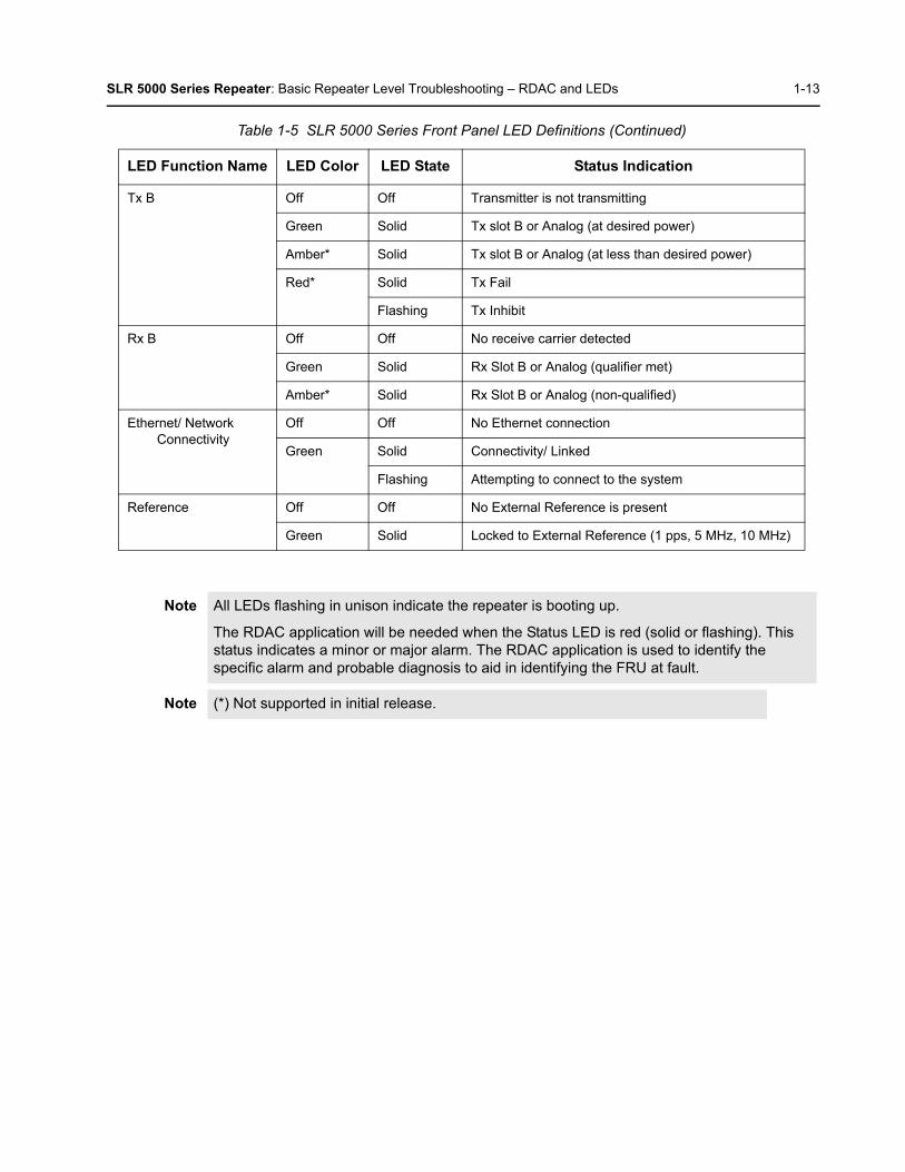
SLR 5000 Series Repeater: Basic Repeater Level Troubleshooting – RDAC and LEDs 1-13
Tx B Off Off Transmitter is not transmitting
Green Solid Tx slot B or Analog (at desired power)
Amber* Solid Tx slot B or Analog (at less than desired power)
Red* Solid Tx Fail
Flashing Tx Inhibit
Rx B Off Off No receive carrier detected
Green Solid Rx Slot B or Analog (qualifier met)
Amber* Solid Rx Slot B or Analog (non-qualified)
Ethernet/ Network Connectivity
Off Off No Ethernet connection
Green Solid Connectivity/ Linked
Flashing Attempting to connect to the system
Reference Off Off No External Reference is present
Green Solid Locked to External Reference (1 pps, 5 MHz, 10 MHz)
Note All LEDs flashing in unison indicate the repeater is booting up.
The RDAC application will be needed when the Status LED is red (solid or flashing). This status indicates a minor or major alarm. The RDAC application is used to identify the specific alarm and probable diagnosis to aid in identifying the FRU at fault.
Note (*) Not supported in initial release.
Table 1-5 SLR 5000 Series Front Panel LED Definitions (Continued)
LED Function Name LED Color LED State Status Indication

1-14 SLR 5000 Series Repeater: Repeater Model Numbering Scheme
1.8 Repeater Model Numbering Scheme
Figure 1-6 Repeater Model Numbering Scheme
Model No.Example : MD R 1 0 Q C G A N Q 1 A N
Position : 1 2 3 4 5 6 7 8 9 10 11 12
Unique VariationN: Standard Package
Version Letter
Package1: Rack Mount/Cabinet Mount
PreselectorQ: Standard Model (none)
Add-on BoardsN: NoneP: Expansion Board
PerformanceA: Standard
Power LevelB: 1–25 WattC: 1–50 Watt
BandJ: 136–174 MHzK: 300–360 MHzP: 350–400 MHzQ: 400–470 MHzT: 450–527 MHzU: 806–941 MHz
Front PanelG: LED Indicators
R: Repeater
AZ: AsiaLA: Latin AmericaAA: North America (except Mexico)MD: Europe/Middle East/Africa/ Australia
MOTOTRBO Repeater Model Series:10: SLR 5000
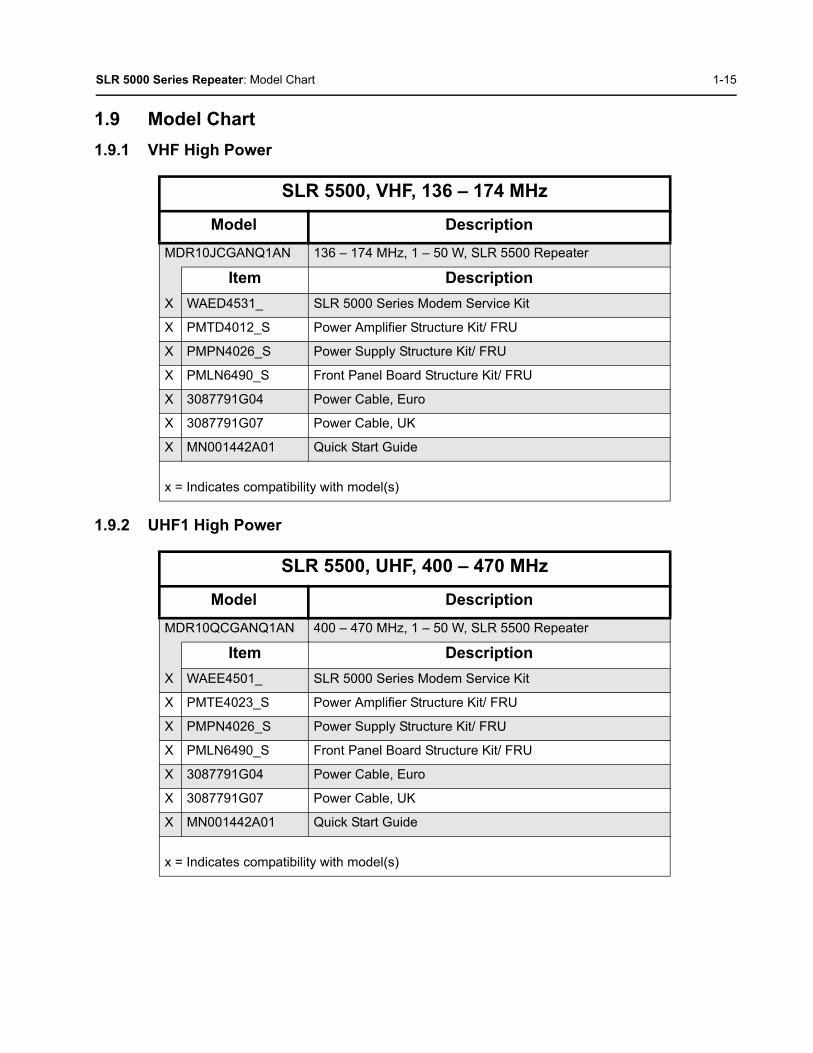
SLR 5000 Series Repeater: Model Chart 1-15
1.9 Model Chart
1.9.1 VHF High Power
1.9.2 UHF1 High Power
SLR 5500, VHF, 136 – 174 MHz
Model Description
MDR10JCGANQ1AN 136 – 174 MHz, 1 – 50 W, SLR 5500 Repeater
Item Description
X WAED4531_ SLR 5000 Series Modem Service Kit
X PMTD4012_S Power Amplifier Structure Kit/ FRU
X PMPN4026_S Power Supply Structure Kit/ FRU
X PMLN6490_S Front Panel Board Structure Kit/ FRU
X 3087791G04 Power Cable, Euro
X 3087791G07 Power Cable, UK
X MN001442A01 Quick Start Guide
x = Indicates compatibility with model(s)
SLR 5500, UHF, 400 – 470 MHz
Model Description
MDR10QCGANQ1AN 400 – 470 MHz, 1 – 50 W, SLR 5500 Repeater
Item Description
X WAEE4501_ SLR 5000 Series Modem Service Kit
X PMTE4023_S Power Amplifier Structure Kit/ FRU
X PMPN4026_S Power Supply Structure Kit/ FRU
X PMLN6490_S Front Panel Board Structure Kit/ FRU
X 3087791G04 Power Cable, Euro
X 3087791G07 Power Cable, UK
X MN001442A01 Quick Start Guide
x = Indicates compatibility with model(s)

1-16 SLR 5000 Series Repeater: Model Chart
Notes

Chapter 2 SLR 5000 Series Satellite Receiver
2.1 DescriptionThe main purpose of the Satellite Receiver is to eliminate “dead zones” in a communications system by improving the “talk-in” coverage on a particular receive frequency when used in a receiver voting system.
The Motorola SLR 5000 series repeater is not offered as an exclusive Satellite Receiver only model, rather the SLR 5000 series can be configured via the CPS to operate as a Satellite Receiver in a receive only mode of operation. As such, the context of this chapter will assume that the SLR 5000 series repeater is configured as a Satellite Receiver.
2.2 Operating FeaturesThe features are identical to the SLR 5000 series repeater, with the exception that all transmitter related functions are not applicable. See Chapter 1: SLR 5000 Series Repeater for more details.
2.3 Frequency RangesThe supported frequency ranges are identical to the SLR 5000 series repeater’s receive frequency ranges. See Chapter 1: SLR 5000 Series Repeater for more details.
2.4 SpecificationsThe specifications are identical to the SLR 5000 series repeater, with the exception that all transmitter related specifications are not applicable. See Chapter 1: SLR 5000 Series Repeater for more details.
Note Configuring the SLR 5000 Series as a Satellite Receiver is only compatible with the MOTOTRBO Digital Voting feature.

2-2 SLR 5000 Series Satellite Receiver: Configuration
2.5 ConfigurationOther than setting the general personality configurations, one must additionally set the “Operation Mode” parameter under the “General Settings” menu in the CPS to that of “Digital Satellite Receiver.”See Figure 2-1 for the screenshot of the “Operation Mode” parameter.
Figure 2-1 “Operation Mode” configuration for Satellite Receiver Functionality

SLR 5000 Series Satellite Receiver: Basic Station Level Troubleshooting – RDAC and LEDs 2-3
2.6 Basic Station Level Troubleshooting – RDAC and LEDsThe troubleshooting procedures are similar to the SLR 5000 series repeater with regards to the control, power supply, and receiver sub-systems. See Chapter 1: SLR 5000 Series Repeater for more details.
2.7 Model ChartThe model chart is identical to the SLR 5000 series repeater. See Section 1.9 on page 1-15 for more details.
Note When configured for receiver only operation, the SLR 5000 series repeater does not supportany transmitter sub-system functions. As such, disregard all references to the transmittersection in Chapter 1: SLR 5000 Series Repeater. This includes any transmitter relatedtopics in the RDAC and the front panel LEDs.

2-4 SLR 5000 Series Satellite Receiver: Model Chart
Notes

Chapter 3 SLR 5000 Series Modem
3.1 DescriptionThe Modem Module is described in this section. A general description, identification of inputs and outputs, and functional theory of operation are provided. The information provided is sufficient to give service personnel a functional understanding of the module, allowing maintenance and troubleshooting to the module level.
3.1.1 General Description
The Modem Module consists of a single printed circuit board in a clamshell housing assembly. It provides the receiver, exciter and station control functionality for the repeater. Additionally the external connections to the station are connected directly to the modem module.
3.1.2 Input and Output Connections
Figure 3-1 shows the Modem Module input and output external connections.
Figure 3-1 Modem Module Connector Locations
Note The modem cooling fan is replaceable and external to the modem itself. See Chapter 11: SLR 5000 Series Maintenance and Disassembly/Reassembly for replacement details.
Front Panel Interface
Auxiliary Connector
DC Power InputTx Exciter Output
Receiver Input
External Reference Input
PA Digital Interface
USB Host
Future Expansion Port
PSU Digital Interface
Future Expansion Ports
Chassis ID Connector
Ethernet Connectors
(-)(+)

3-2 SLR 5000 Series Modem: Receiver Subsystem
3.1.3 Frequency Bands
The Modem Module covers the following bands with unique models:
• 136 – 174 MHz
• 400 – 470 MHz
3.2 Receiver Subsystem
3.2.1 Description
The Modem Module includes the receiver circuitry for the station. A cable connects the board connector to a BNC connector located on the rear panel of the repeater. See Figure 3-1 for the location of this connector. The receiver section performs highly-selective bandpass filtering and dual down-conversion of the desired RF signal. A custom Receiver IC then performs an analog-to-digital conversion of the desired received signal and outputs the digitized signal to the controller section via a serial synchronous interface. Included in the receiver section is:
• Frequency Synthesizer Circuitry – Consists of a phase-locked loop and Voltage-Controlled Oscillator (VCO), generates the first LO injection signal.
• Varactor-tuned Preselector Filter(s) – Provides bandpass filtering of the station Receiver RF input.
• Receiver Front End Circuitry – Performs filtering, amplification, and the first down conversion of the Receiver RF signal.
• Receiver-specific piece of transceiver IC Circuitry – Consists of receiver-specific parts of a transceiver IC which performs the second down conversion, filtering, amplification, and analog-to-digital conversion of the receive signal.
• Analog to Digital Converter (ADC) Circuitry – Converts analog Receiver status signals to digital format for transfer to the controller circuitry located on the Modem Module.
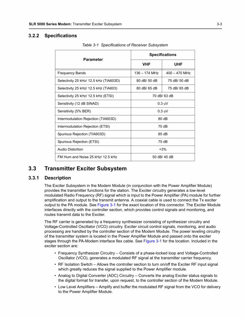
SLR 5000 Series Modem: Transmitter Exciter Subsystem 3-3
3.2.2 Specifications
3.3 Transmitter Exciter Subsystem
3.3.1 Description
The Exciter Subsystem in the Modem Module (in conjunction with the Power Amplifier Module) provides the transmitter functions for the station. The Exciter circuitry generates a low-level modulated Radio Frequency (RF) signal which is input to the Power Amplifier (PA) module for further amplification and output to the transmit antenna. A coaxial cable is used to connect the Tx exciter output to the PA module. See Figure 3-1 for the exact location of this connector. The Exciter Module interfaces directly with the controller section, which provides control signals and monitoring, and routes transmit data to the Exciter.
The RF carrier is generated by a frequency synthesizer consisting of synthesizer circuitry and Voltage-Controlled Oscillator (VCO) circuitry. Exciter circuit control signals, monitoring, and audio processing are handled by the controller section of the Modem Module. The power leveling circuitry of the transmitter system is located in the Power Amplifier Module and passed onto the exciter stages through the PA-Modem interface flex cable. See Figure 3-1 for the location. Included in the exciter section are:
• Frequency Synthesizer Circuitry – Consists of a phase-locked loop and Voltage-Controlled Oscillator (VCO), generates a modulated RF signal at the transmitter carrier frequency.
• RF Isolation Switch – Allows the controller section to turn on/off the Exciter RF input signal which greatly reduces the signal supplied to the Power Amplifier module.
• Analog to Digital Converter (ADC) Circuitry – Converts the analog Exciter status signals to the digital format for transfer, upon request, to the controller section of the Modem Module.
• Low Level Amplifiers – Amplify and buffer the modulated RF signal from the VCO for delivery to the Power Amplifier Module.
Table 3-1 Specifications of Receiver Subsystem
ParameterSpecifications
VHF UHF
Frequency Bands 136 – 174 MHz 400 – 470 MHz
Selectivity 25 kHz/ 12.5 kHz (TIA603D) 80 dB/ 50 dB 75 dB/ 50 dB
Selectivity 25 kHz/ 12.5 kHz (TIA603) 80 dB/ 65 dB 75 dB/ 65 dB
Selectivity 25 kHz/ 12.5 kHz (ETSI) 70 dB/ 63 dB
Sensitivity (12 dB SINAD) 0.3 uV
Sensitivity (5% BER) 0.3 uV
Intermodulation Rejection (TIA603D) 80 dB
Intermodulation Rejection (ETSI) 70 dB
Spurious Rejection (TIA603D) 85 dB
Spurious Rejection (ETSI) 75 dB
Audio Distortion <3%
FM Hum and Noise 25 kHz/ 12.5 kHz 50 dB/ 45 dB
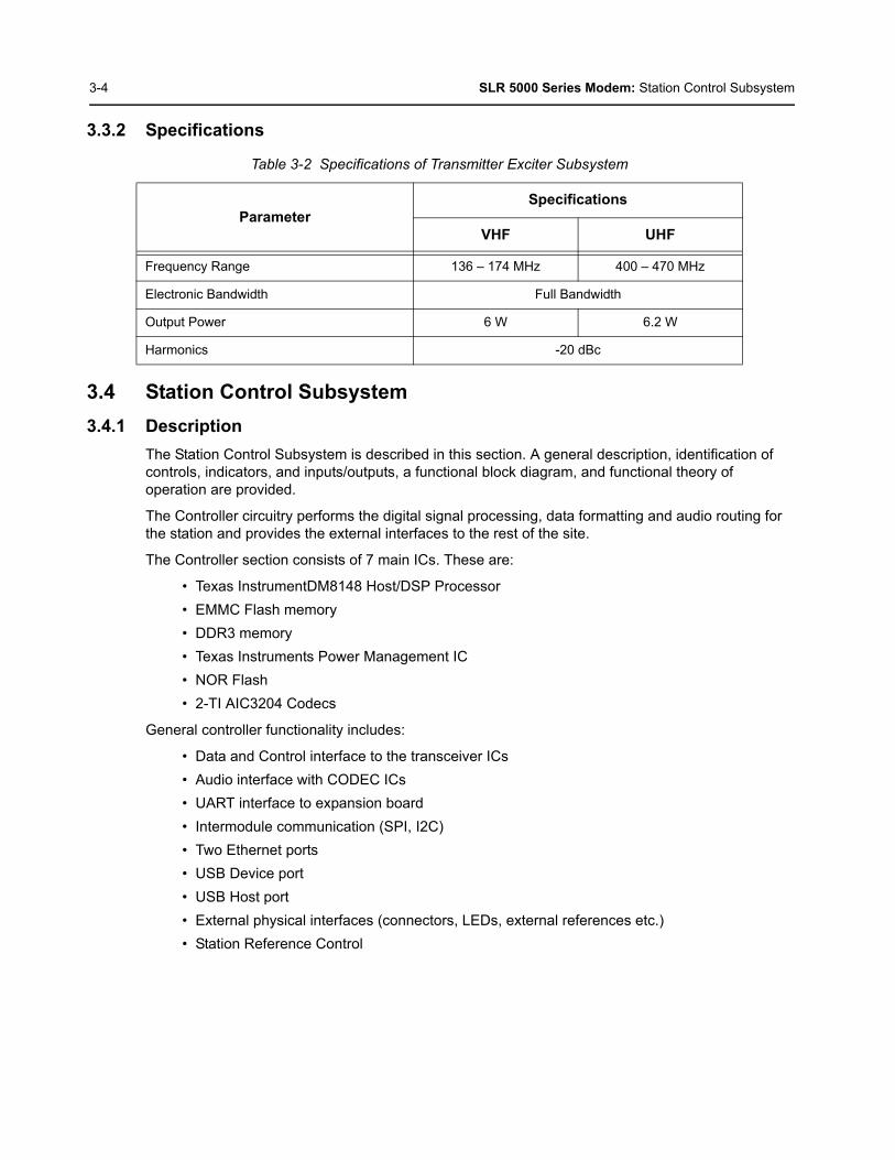
3-4 SLR 5000 Series Modem: Station Control Subsystem
3.3.2 Specifications
3.4 Station Control Subsystem
3.4.1 Description
The Station Control Subsystem is described in this section. A general description, identification of controls, indicators, and inputs/outputs, a functional block diagram, and functional theory of operation are provided.
The Controller circuitry performs the digital signal processing, data formatting and audio routing for the station and provides the external interfaces to the rest of the site.
The Controller section consists of 7 main ICs. These are:
• Texas InstrumentDM8148 Host/DSP Processor
• EMMC Flash memory
• DDR3 memory
• Texas Instruments Power Management IC
• NOR Flash
• 2-TI AIC3204 Codecs
General controller functionality includes:
• Data and Control interface to the transceiver ICs
• Audio interface with CODEC ICs
• UART interface to expansion board
• Intermodule communication (SPI, I2C)
• Two Ethernet ports
• USB Device port
• USB Host port
• External physical interfaces (connectors, LEDs, external references etc.)
• Station Reference Control
Table 3-2 Specifications of Transmitter Exciter Subsystem
ParameterSpecifications
VHF UHF
Frequency Range 136 – 174 MHz 400 – 470 MHz
Electronic Bandwidth Full Bandwidth
Output Power 6 W 6.2 W
Harmonics -20 dBc

SLR 5000 Series Modem: Station Control Subsystem 3-5
3.4.2 High Stability Reference Block
The high-stability reference block can be used to enhance the 0.5 ppm Voltage Controlled Temperature Compensated Crystal Oscillator. The block diagram is shown below in Figure 3-2. An external reference can be applied to lock the on board VCTCXO. This function can be enabled via the customer programming software. The connection is made via a cable connecting a BNC connector on the rear panel to a connector on the modem module. The location of the connector on the modem module can be found in Figure 3-1.
Figure 3-2 High Stability Reference Circuit
3.4.3 Audio
The analog audio stages are used exclusively for external accessories connected through the rear DB25 accessory connector.
The critical components of the audio circuit are the TI DM8148 processor and a pair of Texas Instruments AIC3204 dual channel audio codecs. Figure 3-3 details the specific interconnects between the critical components.
Figure 3-3 Audio Block Diagram
The repeater digital audio is handled primarily by the DM8148 processor. The TX RFIC generates a 24.576 MHz master clock (MCLK) that the DM8148 uses to drive its McASP SSI interface for the audio codecs. The bulk of the audio processing is done in the DaVinci’s DSP core. The audio codecs contain DACs and ADCs and handle the conversion of the digital audio to analog audio and vice versa.
There are 2 TX audio lines routed in from the rear accessory connector. These are TX Audio 1 (Pins 1 and 22, used for analog and slot 1 digital), and TX Data (Pin 13).
For the RX outputs, there is only 1 which is connected to the accessory connector. RX Audio 1 on pin 7 (to be used for analog and slot 1 digital).
19.2MHzVCTCXO
DAC Output from
Transceiver IC
PLL
Ref_Lck_Det
Lock Detect
Tune
STD_EN
VCTCXO
LOOP FILTER
Phase Detector
Loop Divider
SPI
External Reference
TI DM8148(DSP Core)
TI AIC3204Audio
Codec 1
TI AIC3204Audio
Codec 2
Rear A
ccessory Connector
(DB
25)I²C2 (2)
I²C0 (2)
Audio SSI (4)
TX Audio 1 (Pin 1 & 22)
RX Audio 1 (Pin 7)
TX Data (Pin 13)
RFIC SSI (4)
RX Audio 1
RX Audio 2
TX Audio 1
TX Data
TX Audio 2
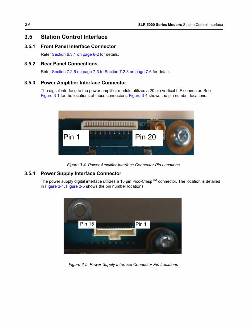
3-6 SLR 5000 Series Modem: Station Control Interface
3.5 Station Control Interface
3.5.1 Front Panel Interface Connector
Refer Section 6.3.1 on page 6-2 for details.
3.5.2 Rear Panel Connections
Refer Section 7.2.5 on page 7-3 to Section 7.2.8 on page 7-6 for details.
3.5.3 Power Amplifier Interface Connector
The digital interface to the power amplifier module utilizes a 20 pin vertical LIF connector. See Figure 3-1 for the locations of these connectors. Figure 3-4 shows the pin number locations.
Figure 3-4 Power Amplifier Interface Connector Pin Locations
3.5.4 Power Supply Interface Connector
The power supply digital interface utilizes a 15 pin Pico-ClaspTM connector. The location is detailed in Figure 3-1. Figure 3-5 shows the pin number locations.
Figure 3-5 Power Supply Interface Connector Pin Locations
Pin 1 Pin 20
Pin 15 Pin 1
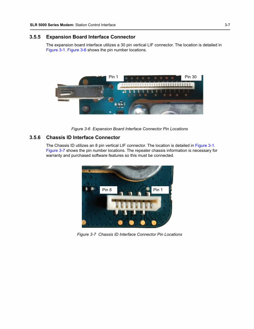
SLR 5000 Series Modem: Station Control Interface 3-7
3.5.5 Expansion Board Interface Connector
The expansion board interface utilizes a 30 pin vertical LIF connector. The location is detailed in Figure 3-1. Figure 3-6 shows the pin number locations.
Figure 3-6 Expansion Board Interface Connector Pin Locations
3.5.6 Chassis ID Interface Connector
The Chassis ID utilizes an 8 pin vertical LIF connector. The location is detailed in Figure 3-1. Figure 3-7 shows the pin number locations. The repeater chassis information is necessary for warranty and purchased software features so this must be connected.
Figure 3-7 Chassis ID Interface Connector Pin Locations
Pin 1 Pin 30
Pin 8 Pin 1

3-8 SLR 5000 Series Modem: Station Control Interface
Notes

Chapter 4 SLR 5000 Series Power Amplifier
4.1 DescriptionThe Power Amplifier Module is described in this section. A general description, identification of inputs and outputs and functional theory of operation are provided. The information provided is sufficient to give service personnel a functional understanding of the module, allowing maintenance and troubleshooting to the module level.
4.2 General DescriptionThe Power Amplifier (PA) is a forced convection-cooled RF power amplifier. It accepts a low-level modulated RF signal from the Exciter Module, and amplifies it for transmission via the site transmit antenna port. The PA is non-linear, and is therefore used for Continuous Wave (CW) applications only. The output power is continually monitored and regulated by a feedback and control loop, with a power output control voltage being generated by the transmitter control circuitry located on the PA. All configuration and control signals are connected to the modem module via the flex connected between the modules.
Note The power amplifier cooling fan is replaceable and external to the power amplifier itself. See Chapter 11: SLR 5000 Series Maintenance and Disassembly/Reassembly for replacement details.
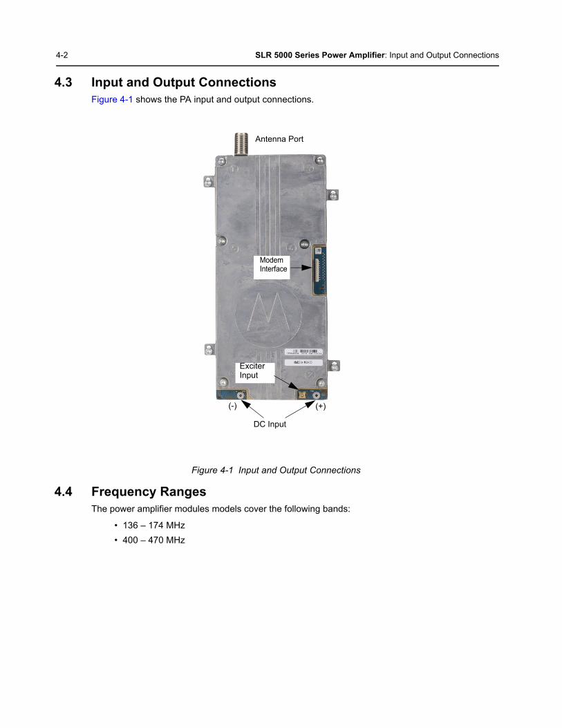
4-2 SLR 5000 Series Power Amplifier: Input and Output Connections
4.3 Input and Output ConnectionsFigure 4-1 shows the PA input and output connections.
Figure 4-1 Input and Output Connections
4.4 Frequency RangesThe power amplifier modules models cover the following bands:
• 136 – 174 MHz
• 400 – 470 MHz
Antenna Port
DC Input
(+)(-)
Modem Interface
Exciter Input

SLR 5000 Series Power Amplifier: Specifications 4-3
4.5 SpecificationsTable 4-1 shows the specifications of SLR 5000 series repeater’s Power Amplifier (PA).
4.6 Modem InterfaceThe digital interface to the modem module utilizes a 20 pin vertical LIF connector. It’s location is shown in Figure 4-1. See Figure 4-2 for front panel interface connector pin locations.
Figure 4-2 Modem Interface Connector Pin Locations
Table 4-1 Specifications of Power Amplifier
ParameterSpecifications Specifications
VHF UHF
Operational Frequency Range 136 – 174 MHz 400 – 470 MHz
Minimum Input Return Loss (Tx mode) 15 dB
Rated RF Input Power 37 dBm
Maximum Standby Power Consumption 0.5 W
Rated RF Output Power Range 1 – 50 W
Supply Nominal Voltage * 13.6 V (+/- 10%)
Maximum Current Draw ** 12.0 A
Note (*) When the SLR 5000 series repeater is operating from a DC source, the PA input voltagefollows the repeater’s DC input source.(**) Nominal VSWR conditions (VSWR <1.5:1)
Pin 20 Pin 1

4-4 SLR 5000 Series Power Amplifier: Modem Interface
Notes

Chapter 5 SLR 5000 Series Power Supply
5.1 DescriptionIn this chapter, a general description, performance specifications, and identification of the inputs and outputs are given for the power supply. The information provided is sufficient to give service personnel a functional understanding of the module, allowing maintenance and troubleshooting to the module level. (See Chapter 11: SLR 5000 Series Maintenance and Disassembly/Reassembly for detailed removal or installation procedures for all modules in the SLR 5000 series repeater.)
5.1.1 General Description
The power supply, with front-to-rear airflow, operates from either an AC or DC input and provides the DC operating voltage for the SLR 5000 series repeater. The power supply also provides an integrated battery charger to maintain the charge on a negatively grounded 12 VDC (nominal) battery system. Figure 5-1 displays the front and rear views of the SLR 5000 series Power Supply.
Additionally, the power supply affords the following performance features:
• Power Factor Correction (PFC) – aids in lowering the ampacity requirements of the AC power source.
• Over-Voltage Protection (OVP) – lowers the risk of damaging the repeater should input AC or DC levels approach damaging levels.
• Over-Current Protection (OCP) – aids in preventing a cascaded failure within the repeater.
• Reverse Polarity Protection – aids in preventing damage to the repeater due to installation mishaps.
• Configurable Battery Charger Voltage – tailors the float voltage to your battery manufactures charging recommendations.
• Configurable Low Voltage Disconnect (LVD) – tailors the battery disconnect voltage to your battery manufactures recommendations.
• Configurable Power Source Preference – when both AC and DC sources are present (and within their respective operational bounds), this feature allows one to select the primary power source the repeater uses.
• Battery Revert – should the AC source be interrupted, this function allows the power supply to seamlessly transfer to a DC source until the AC source is restored. This results in uninterrupted radio service for as long as DC power can be provided.
Note A user supplied external 12 V (nominal) battery system is required to support the battery backup feature so that when the AC power fails, the SLR 5000 series repeater can be powered from a DC battery source if it is connected to the PS.
Note The power supply cooling fan is replaceable and external to the power supply itself. See Chapter 11: SLR 5000 Series Maintenance and Disassembly/Reassembly for replacement details.
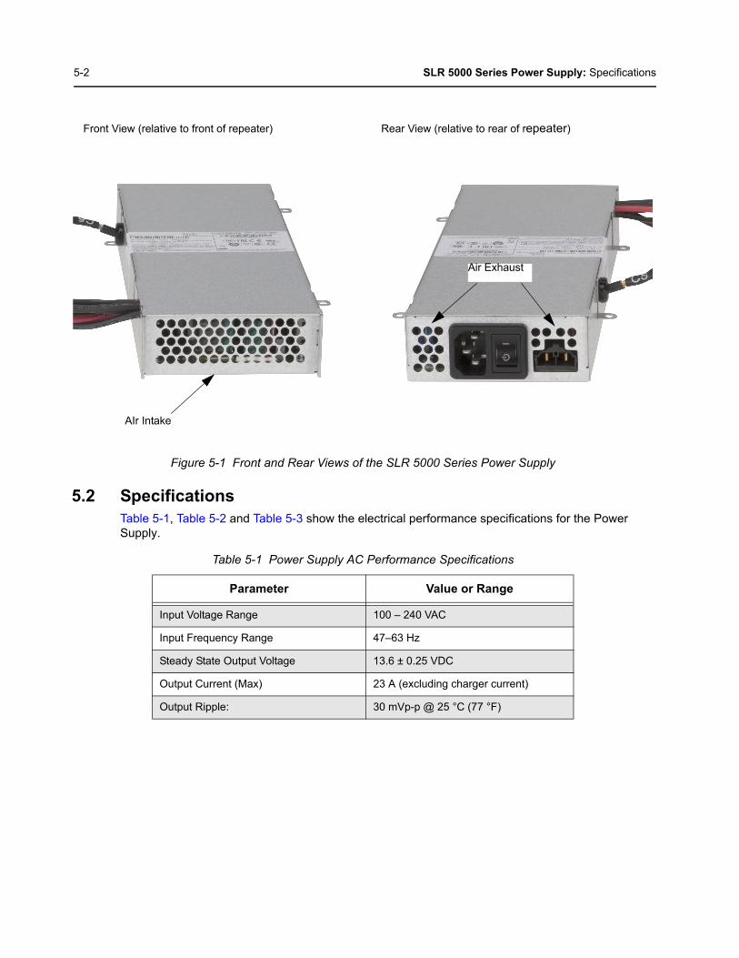
5-2 SLR 5000 Series Power Supply: Specifications
Figure 5-1 Front and Rear Views of the SLR 5000 Series Power Supply
5.2 SpecificationsTable 5-1, Table 5-2 and Table 5-3 show the electrical performance specifications for the Power Supply.
Table 5-1 Power Supply AC Performance Specifications
Parameter Value or Range
Input Voltage Range 100 – 240 VAC
Input Frequency Range 47–63 Hz
Steady State Output Voltage 13.6 ± 0.25 VDC
Output Current (Max) 23 A (excluding charger current)
Output Ripple: 30 mVp-p @ 25 °C (77 °F)
Front View (relative to front of repeater) Rear View (relative to rear of repeater)
AIr Intake
Air Exhaust

SLR 5000 Series Power Supply: Power Supply Interface 5-3
5.3 Power Supply Interface
5.3.1 Power Source Inputs
Figure 5-2 Power Source Inputs
Table 5-2 Power Supply DC Performance Specifications
Parameter Value or Range
Input Voltage Range 11 – 15.5VDC
Steady State Output Voltage Input voltage dependent (0 – 0.4 V below input)
Output Current (Max) 26 A
Output Ripple: 30 mV p-p, @ 25 °C (77 °F)
Table 5-3 Power Supply Battery Charger Performance Specifications
Parameter Value or Range
Charging Voltage Range 13.5 – 14.2 VDC (default 13.8 VCD: configurable)
Charging Current (Max) 3 A (in addition to output current)
Note When the power switch is in standby, all outputs are disabled (regardless of input source(s)connected). This includes the charger output as well (if charging is enabled).
AC Source Input Connector Power Switch DC Source Input Connector(also charging output)

5-4 SLR 5000 Series Power Supply: Power Supply Interface
5.3.2 Power Supply Outputs
Figure 5-3 Power Supply Outputs
5.3.3 Power Supply Digital Interface
Figure 5-4 Power Supply Digital Interface
Power Supply Fan
Power Amplifier
Modem
Modem Fan
Power Amplifier Fan
Pin 15Pin 1
Modem Interface
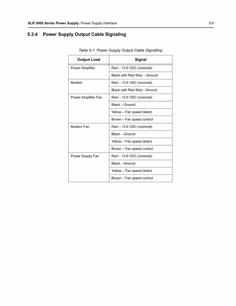
SLR 5000 Series Power Supply: Power Supply Interface 5-5
5.3.4 Power Supply Output Cable Signaling
Table 5-1 Power Supply Output Cable SIgnalling
Output Load Signal
Power Amplifier Red – 13.6 VDC (nominal)
Black with Red Strip – Ground
Modem Red – 13.6 VDC (nominal)
Black with Red Strip - Ground
Power Amplifier Fan Red – 13.6 VDC (nominal)
Black – Ground
Yellow – Fan speed detect
Brown – Fan speed control
Modem Fan Red – 13.6 VDC (nominal)
Black – Ground
Yellow – Fan speed detect
Brown – Fan speed control
Power Supply Fan Red – 13.6 VDC (nominal)
Black – Ground
Yellow – Fan speed detect
Brown – Fan speed control

5-6 SLR 5000 Series Power Supply: Power Supply Interface
Notes

Chapter 6 SLR 5000 Series Front Panel
6.1 DescriptionThe Front Panel Module is described in this section. A general description, identification of inputs and outputs and functional theory of operation are provided. The information provided is sufficient to give service personnel a functional understanding of the module, allowing maintenance and troubleshooting to the module level.
6.1.1 General Description
The Front Panel board user interface includes 7 LED indicators and a USB device port. The board is connected to the modem via a 30 pin flex cable. The LED indicators inform the user of the state of the repeater while the USB device port is used to interface with the repeater through the Customer Programming Software (CPS). The LED indications are transferred to the front panel via a serial peripheral interface.
6.2 Input and Output ConnectionsFigure 6-1 shows the various front panel Input and Output connections.
.
Figure 6-1 Front Panel Input and Output Connections
Modem Interface
USB Device Connector
LED Indicators
Pin 1 Pin 30
USB Device
Connector
LED Indicators
6-2 SLR 5000 Series Front Panel: Interfaces
6.3 Interfaces
6.3.1 Modem Interface
The interface to the modem is made via a 30 pin flex cable. The connector on the front panel board is a 30 pin horizontal LIF connector. The location can be seen in Figure 6-1.
6.3.2 User/ Service Interface
6.3.2.1 USB
The Front Panel USB device port is the interface used for connecting the repeater to a computer in order to use the Customer Programming Software. See Figure 6-1 for the location. A standard “Type A” to “Type B” USB cable facilitates the connection.
6.3.2.2 LED Indicators
The Front Panel houses 7 LED indicators used for displaying the state of the repeater. For state details, refer to Table 1-5 on page 1-12.
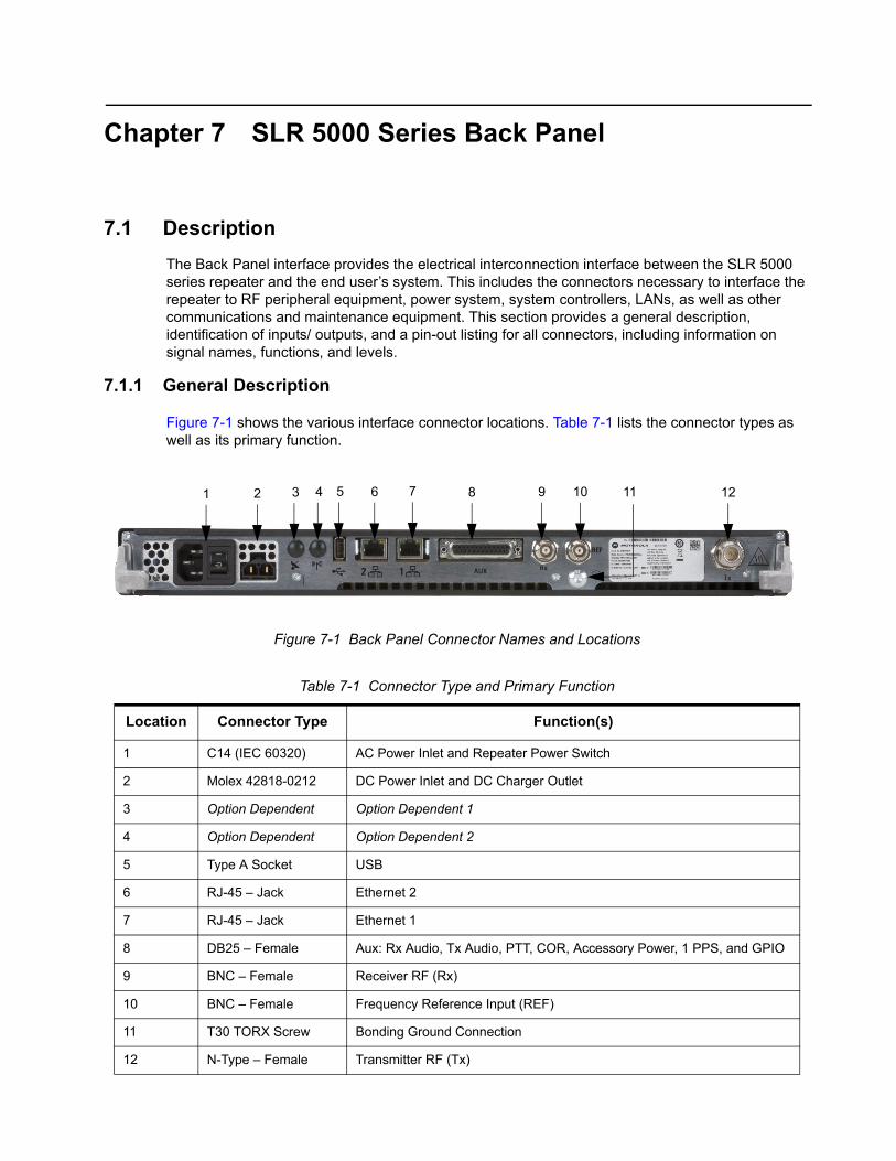
Chapter 7 SLR 5000 Series Back Panel
7.1 Description
The Back Panel interface provides the electrical interconnection interface between the SLR 5000 series repeater and the end user’s system. This includes the connectors necessary to interface the repeater to RF peripheral equipment, power system, system controllers, LANs, as well as other communications and maintenance equipment. This section provides a general description, identification of inputs/ outputs, and a pin-out listing for all connectors, including information on signal names, functions, and levels.
7.1.1 General Description
Figure 7-1 shows the various interface connector locations. Table 7-1 lists the connector types as well as its primary function.
Figure 7-1 Back Panel Connector Names and Locations
Table 7-1 Connector Type and Primary Function
Location Connector Type Function(s)
1 C14 (IEC 60320) AC Power Inlet and Repeater Power Switch
2 Molex 42818-0212 DC Power Inlet and DC Charger Outlet
3 Option Dependent Option Dependent 1
4 Option Dependent Option Dependent 2
5 Type A Socket USB
6 RJ-45 – Jack Ethernet 2
7 RJ-45 – Jack Ethernet 1
8 DB25 – Female Aux: Rx Audio, Tx Audio, PTT, COR, Accessory Power, 1 PPS, and GPIO
9 BNC – Female Receiver RF (Rx)
10 BNC – Female Frequency Reference Input (REF)
11 T30 TORX Screw Bonding Ground Connection
12 N-Type – Female Transmitter RF (Tx)
2 3 6 8 9 10 11 124 5 71

7-2 SLR 5000 Series Back Panel: Back panel Interfaces
7.2 Back panel Interfaces
7.2.1 AC Power Inlet
The AC power inlet connector is of the C14 type socket (IEC 60320) and accepts interface to C13 type plugged (IEC 60320) power cords. Figure 7-2 shows the location of the pins and Table 7-2 lists the functional characteristics of the connector’s pins.
Figure 7-2 AC Power Inlet Connector and Repeater Power Switch
7.2.2 DC Power Inlet / DC Charger Outlet
The DC power inlet / DC charger outlet connector is a Molex 42818-02012 panel mount receptacle and accepts interface to Molex 42816-0212 plugs. Figure 7-3 shows the location of the pins and Table 7-3 lists the functional characteristics of the connector’s pins.
Figure 7-3 DC Power Inlet/ DC Charger Outlet Connector
Table 7-2 AC Power Inlet Connector
Location Pin Assignment Type Signal Characteristics
1 EarthPower 100 – 240 VAC (Line to Neutral)
4 A (max)2 Line
3 Neutral
Table 7-3 DC Power Inlet/ DC Charger Outlet Connector
Location Pin Assignment Type Signal Characteristics
1 Positive Power 11 – 14.4 VDC17 A (max)
2 Negative
1
2
3
ON (fully powered)
STANDBY
1 2
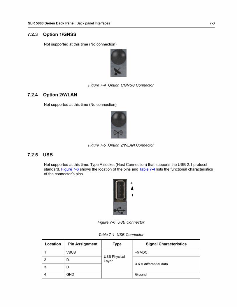
SLR 5000 Series Back Panel: Back panel Interfaces 7-3
7.2.3 Option 1/GNSS
Not supported at this time (No connection)
Figure 7-4 Option 1/GNSS Connector
7.2.4 Option 2/WLAN
Not supported at this time (No connection)
Figure 7-5 Option 2/WLAN Connector
7.2.5 USB
Not supported at this time. Type A socket (Host Connection) that supports the USB 2.1 protocol standard. Figure 7-6 shows the location of the pins and Table 7-4 lists the functional characteristics of the connector’s pins.
Figure 7-6 USB Connector
Table 7-4 USB Connector
Location Pin Assignment Type Signal Characteristics
1 VBUSUSB Physical Layer
+5 VDC
2 D-3.6 V differential data
3 D+
4 GND Ground
4
1

7-4 SLR 5000 Series Back Panel: Back panel Interfaces
7.2.6 Ethernet 1
Fully compliant with IEEE and 802.3 and 802.3u standards. Supports 10Base-T, 100Base-Tx rates, full duplex, half duplex mode and flow control. Figure 7-7 shows the location of the pins andTable 7-5 lists the functional characteristics of the connector’s pins.
Figure 7-7 Ethernet 1 Connector
Table 7-5 Ethernet 1 Connector
Location Pin Assignment Type Signal Characteristics
1 Ethernet Tx+
Ethernet Physical Layer
5 V differential data2 Ethernet Tx-
3 Ethernet Rx+
4 Unused N/A
5 Unused N/A
6 Ethernet Rx- 5 V differential data
7 Unused N/A
8 Unused N/A
8 1

SLR 5000 Series Back Panel: Back panel Interfaces 7-5
7.2.7 Ethernet 2
Not supported at this time. Fully compliant with IEEE and 802.3 and 802.3u standards. Supports 10Base-T, 100Base-Tx rates, full duplex, half duplex mode and flow control. Figure 7-8 shows the location of the pins and Table 7-6 lists the functional characteristics of the connector’s pins.
Figure 7-8 Ethernet 2 Connector
Table 7-6 Ethernet 2 Connector
Location Pin Assignment Type Signal Characteristics
1 Ethernet Tx+
Ethernet Physical Layer
5 V differential data2 Ethernet Tx-
3 Ethernet Rx+
4 Unused N/A
5 Unused N/A
6 Ethernet Rx- 5 V differential data
7 Unused N/A
8 Unused N/A
8 1

7-6 SLR 5000 Series Back Panel: Back panel Interfaces
7.2.8 Auxiliary (Aux)
This connection supports the analog interface to the SLR 5000 series repeater, which includes audio, station control, station indicators, accessory power, and provisions for timing used in various system implementations. Figure 7-9 shows the location of the pins and Table 7-7 lists the functional characteristics of the connector’s pins.
Figure 7-9 Auxiliary Connector
Table 7-7 Auxiliary Connector
Location Pin Assignment Type Signal Characteristics
1 Tx Audio 1 Audio Transmit Audio – Nominal input level is 80 mVrms for 60% deviation with scaling factor set to 100%. 600 Ω input impedance.
2 GPIO 1 Digital Output Logic Low: 0.5 VDC maxOutput Logic High: Open Collector with 10 k pull-up to 5 VInput Logic Low: 0 – 0.8 VDCInput Logic High: 3.0 – 14 VDC
3 *Rx Audio 2 Audio Receiver Audio – Nominal output level is 330 mVrms (into a 50 k Ohm load) with a 60% deviation receive signal.1000 Ω output impedance.
4 GPIO 2 Digital Output Logic Low: 0.5 VDC maxOutput Logic High: Open Collector with 10 k pull-up to 5 VInput Logic Low: 0 – 0.8 VDCInput Logic High: 3.0 – 14 VDC
5 GPIO 10/ *Analog Input 2
Digital Output Logic Low: 0.5 VDC maxOutput Logic High: Open Collector with 10 k pull-up to 5 VInput Logic Low: 0 – 0.8 VDCInput Logic High: 3.0 – 14 VDC
Analog: 0 – 5 VDC
13 1
1425

SLR 5000 Series Back Panel: Back panel Interfaces 7-7
6 GPIO 9/ *Analog Input 1
Digital Output Logic Low: 0.5 VDC maxOutput Logic High: Open Collector with 10 k pull-up to 5 VInput Logic Low: 0 – 0.8 VDCInput Logic High: 3.0 – 14 VDC
Analog: 0 – 5 VDC
7 Rx Audio 1 Audio Receiver Audio – Nominal output level is 330 mVrms (into a 50 k Ohm load) with a 60% deviation receive signal.1000 Ω output impedance.
8 GPIO 6 Digital Receiver Audio – Nominal output level is 330 mVrms with a 60% deviation receive signal. 1000 Ω output impedance.
9 Ground
10 GPIO 7/ *Analog RSSI Out
Digital or Analog
Digital:Output Logic Low: 0.5 VDC maxOutput Logic High: Open Collector with 10 k pull-up to 5 VInput Logic Low: 0 – 0.8 VDCInput Logic High: 3.0 – 14 VDC
Analog RSSI:Typically 0.5 VDC for -120 dBm to 2.7 VDC for -60 dBm carrier. Variation with carrier level at approximately 50 mV/dBm.
11 GPIO 11/ *Analog Input 3
Digital or Analog
Digital:Output Logic Low: 0.5 VDC maxOutput Logic High: Open Collector with 10 k pull-up to 5 VInput Logic Low: 0 – 0.8 VDCInput Logic High: 3.0 – 14 VDC
Analog: 0 – 5 VDC
12 GPIO 12/ *Analog Input 4
Digital or Analog
Digital:Output Logic Low: 0.5 VDC maxOutput Logic High: Open Collector with 10 k pull-up to 5 VInput Logic Low: 0 – 0.8 VDCInput Logic High: 3.0 – 14 VDC
Analog: 0 – 5 VDC
13 Tx Data Digital or Analog
Transmit Data/ PL/ DPL – Nominal input level is 80 mVrmsfor 20% deviation with scaling factor set to 100%. 600 Ω input impedance.
14 *1 PPS In/ Out Digital Output Logic Low: 0.5 VDC maxOutput Logic High: Open Collector with 10 k pull-up to 5 VInput Logic Low: 0 – 0.8 VDCInput Logic High: 3.0 – 14 VDC
15 GPIO 3 Digital Output Logic Low: 0.5 VDC maxOutput Logic High: Open Collector with 10 k pull-up to 5 VInput Logic Low: 0 – 0.8 VDCInput Logic High: 3.0 – 14 VDC
Table 7-7 Auxiliary Connector (Continued)
Location Pin Assignment Type Signal Characteristics
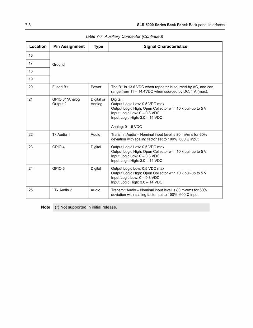
7-8 SLR 5000 Series Back Panel: Back panel Interfaces
16
Ground17
18
19
20 Fused B+ Power The B+ is 13.6 VDC when repeater is sourced by AC, and can range from 11 – 14.4VDC when sourced by DC. 1 A (max).
21 GPIO 8/ *Analog Output 2
Digital or Analog
Digital:Output Logic Low: 0.5 VDC maxOutput Logic High: Open Collector with 10 k pull-up to 5 VInput Logic Low: 0 – 0.8 VDCInput Logic High: 3.0 – 14 VDC
Analog: 0 – 5 VDC
22 Tx Audio 1 Audio Transmit Audio – Nominal input level is 80 mVrms for 60% deviation with scaling factor set to 100%. 600 Ω input
23 GPIO 4 Digital Output Logic Low: 0.5 VDC maxOutput Logic High: Open Collector with 10 k pull-up to 5 VInput Logic Low: 0 – 0.8 VDCInput Logic High: 3.0 – 14 VDC
24 GPIO 5 Digital Output Logic Low: 0.5 VDC maxOutput Logic High: Open Collector with 10 k pull-up to 5 VInput Logic Low: 0 – 0.8 VDCInput Logic High: 3.0 – 14 VDC
25 * Tx Audio 2 Audio Transmit Audio – Nominal input level is 80 mVrms for 60% deviation with scaling factor set to 100%. 600 Ω input
Note (*) Not supported in initial release.
Table 7-7 Auxiliary Connector (Continued)
Location Pin Assignment Type Signal Characteristics

SLR 5000 Series Back Panel: Back panel Interfaces 7-9
7.2.9 Frequency Reference
The Frequency Reference port is a BNC (female) type connector. Figure 7-10 depicts the Frequency Reference connector.
Figure 7-10 Frequency Reference Connector
Various external frequency reference signal types can be provided to the SLR 5000 series repeater for normal operation. Table 7-8 provides a list of acceptable input signal types as well as their permissible levels
7.2.10 Receiver RF
The Receiver RF port is a BNC (female) type connector. Figure 7-11 depicts the Receiver RF connector.
Figure 7-11 Receiver RF Connector
Table 7-8 Frequency Reference
Frequency (MHz) Waveform * Level (Vpp) Impedance (Ω)** Note
5 Sine 1.5 – 5.3 100 k AC Coupled
5 Square* 1.5 – 5.3 100 k AC Coupled
10 Sine 1.5 – 5.3 100 k AC Coupled
10 Square* 1.5 – 5.3 100 k AC Coupled
Note (*) Square wave duty cycle range is 45 – 50%.(**) Impedance of the SLR 5000 series repeater’s frequency reference port.
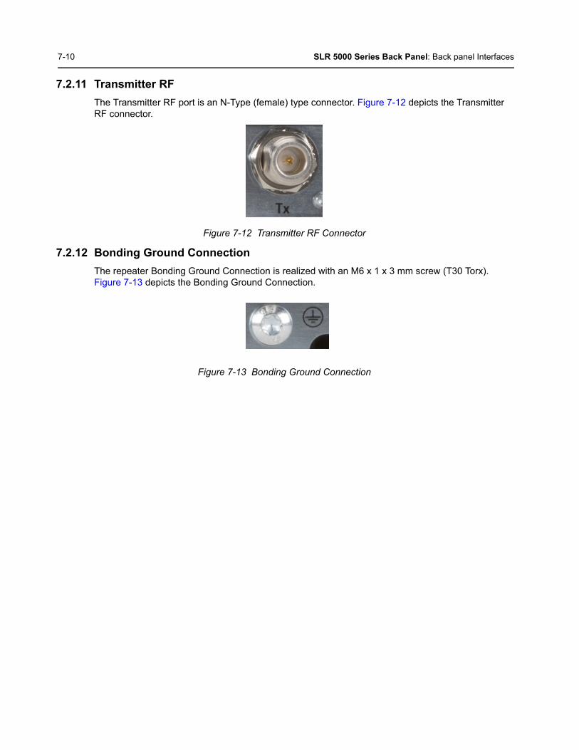
7-10 SLR 5000 Series Back Panel: Back panel Interfaces
7.2.11 Transmitter RF
The Transmitter RF port is an N-Type (female) type connector. Figure 7-12 depicts the Transmitter RF connector.
Figure 7-12 Transmitter RF Connector
7.2.12 Bonding Ground Connection
The repeater Bonding Ground Connection is realized with an M6 x 1 x 3 mm screw (T30 Torx). Figure 7-13 depicts the Bonding Ground Connection.
Figure 7-13 Bonding Ground Connection

Chapter 8 SLR 5000 Series Test Equipment And Service Aids
8.1 Recommended Test EquipmentThe list of equipment contained in Table 8-1 includes most of the standard test equipment required for servicing Motorola SLR 5000 series repeaters.
Table 8-1 Recommended Test Equipment
Equipment Characteristic Example Application
Service Monitor Can be used as a substitute for items marked with an asterisk (*)
Aeroflex 3920 Digital Radio Test Set or equivalent
Frequency/deviation meter and signal generator for wide-range troubleshooting and alignment
Digital RMS Multimeter*
100 µV to 300V5 Hz to 1 MHz10 MΩ Impedance
Fluke 179 or equivalent (www.fluke.com)
AC/DC voltage and current measurements. Audio voltage measurements
RF Signal Generator*
100 MHz to 1 GHz -130 dBM to +10 dBM FM Modulation 0 kHz to 10 kHz
Keysight N5181A (www.keysight.com), Ramsey RSG1000B (www.ramseyelectronics.com), or equivalent
Receiver measurements
Oscilloscope* 2 Channel50 MHz Bandwidth5 mV/div to 20 V/div
Leader LS8050(www.leaderusa.com), Tektronix TDS1001b (www.tektronix.com), or equivalent
Waveform measurements
Power Meter and Sensor*
5% Accuracy100 MHz to 500 MHz50 Watts
Bird 43 Thruline Watt Meter(www.bird-electronic.com) or equivalent
Transmitter power output measurements
RF Millivolt Meter
100 mV to 3V RF10 kHz to 1 GHz
Boonton 92EA (www.boonton.com) or equivalent
RF level measurements

8-2 SLR 5000 Series Test Equipment And Service Aids: Service Aids
8.2 Service AidsSection A.1.5 on page A-2 lists the service aids recommended for working on the SLR 5000 series repeater. While all of these items are available from Motorola, most are standard workshop equipment items, and any equivalent item capable of the same performance may be substituted for the item listed.

Chapter 9 SLR 5000 Series Performance Check or Testing
9.1 GeneralThe SLR 5000 series repeater meets published specifications through the manufacturing process by utilizing high-accuracy laboratory-quality test equipment. The recommended field service equipment approaches the accuracy of the manufacturing equipment with few exceptions. This accuracy must be maintained in compliance with the equipment manufacturer’s recommended calibration schedule.
9.2 Transmitter Testing
9.2.1 Introduction
While most module faults can be detected by running the repeater diagnostics, the following procedure provides a more traditional method of troubleshooting the transmitter circuitry.
This procedure allows the service technician to make minor adjustments and verify proper operation of the repeater transmit circuitry, including:
• Exciter Section of Modem Module
• Power Amplifier Module
• Power Supply Module
In general, the transmitter circuitry is exercised by injecting and measuring signals using a Service Monitor (or equivalent). Incorrect measurement values indicate a faulty module(s); measurement values within the acceptable range verify proper operation of the above listed modules and circuitry.
9.2.2 Test Equipment
The following test equipment are required to perform the procedure:
• Aeroflex 3920 Digital Radio Test Set (or equivalent)
• Microphone (GMMN4063_)
• Power Meter and Sensor
• Station Rear Accessory Test Cable
• Dummy Load (50 Ω, repeater wattage or higher)
Note Although these repeaters function in digital and analog modes, all testing is done in analogmode. Digital Repeater tests can be performed using an Aeroflex 3900 Series ServiceMonitor, if the DMR Digital Repeater Test Option is purchased. This auto testing could beperformed in lieu of the Manual testing described below.
The repeater needs to be taken out of service in order to carry out performance testing procedures. Unless the repeater is already out of service, it is recommended to perform the procedures during off-peak hours in order to minimize disruption of service to the system subscribers.
9-2 SLR 5000 Series Performance Check or Testing: Transmitter Testing
9.2.3 Verifying Transmitter Circuitry Procedure
1. Connect and set up test equipment as shown in Figure 9-1.
2. Apply input power (AC or DC) to the repeater. The power supply, modem and PA fans should run a few seconds to confirm fan operation.
3. Press the PTT switch of the microphone and observe the PA Keyed LED indicator on the Repeater Front Panel.
• If PA Keyed fails to light, suspect the following:
- Faulty Power Amplifier Module
- Faulty Modem Module
- Loose or bad Exciter-to-PA RF cable
- Loose or bad PA-to-antenna RF output cable
- Improperly terminated PA RF output cable
- Faulty Power Supply Module
4. Measure output power by pressing the PTT button and observing reading on an in-line wattmeter.
• If PA output is not at proper power (as set for particular site), adjust the output power as described in the CPS online help.
5. If PA output power is proper, set up the Service Monitor for spectrum analyzer display. Press the PTT button and observe the display. The display should show a single frequency carrier:
• If the display shows multiple carriers evenly spaced about the carrier, suspect a faulty Exciter module or PA module.
• If the display shows a solid carrier but it is off frequency, suspect the following:
- Faulty Modem Module
- Faulty external 5/10 MHz reference source (if used)
• If the display shows a single carrier moving erratically, suspect a faulty Modem Module.
6. If display is proper, set up Aeroflex 3900 Series Communications System Analyzer to display modulation. Using the microphone, push the PTT button and speak into the microphone. Verify that the display shows an audio signal.
• If the proper display is not obtained, suspect faulty SCM or Exciter Module
7. Set the Aeroflex 3900 Series Communications System Analyzer for GEN/ MON MTR. Press the PTT button and speak loudly into the microphone to cause maximum deviation. Display should read:
- 4.60 kHz maximum for a 25 kHz system
- 3.68 kHz maximum for a 20 kHz system
- 2.30 kHz maximum for a 12.5 kHz system
• If the proper display is not obtained, suspect faulty SCM or Exciter Module.
8. This completes the Verifying Transmitter Circuitry test procedure. If all displays and measurements are correct, the transmitter circuitry may be considered to be operating properly.

SLR 5000 Series Performance Check or Testing: Transmitter Testing 9-3
Figure 9-1 Test Equipment Setup for Verifying Transmitter Circuitry
HELPTAB
1
SELECT
CANCEL
IFR 390I Digital Radio Test Set
TEST HOLD
CONFIG
UTILS ENTER
MIC / ACC GEN T/R ANT
RETURN
TEST PORT CH1 SCOPE CH2 1 2AUDIO INFCTN GEN / DEMOD OUT
0 .#
ASSIGN
–*
2
4 5 6
7
HELP
8 9
3
T/R
Power Meter
Dummy Load
Tx
(Step 5)
Microphone(GMMN4063_)
9-4 SLR 5000 Series Performance Check or Testing: Receiver Testing
9.3 Receiver Testing
9.3.1 Introduction
While most module faults can be detected by running the repeater diagnostics, the following procedure provides a more traditional method of troubleshooting the Receiver circuitry.
This procedure allows the service technician to make minor adjustments and verify proper operation of the repeater receive circuitry on the Modem Module.
In general, the Receiver circuitry is exercised by injecting and measuring signals using a Service Monitor (or equivalent). Incorrect measurement values indicate a faulty module(s); measurement values within the acceptable range verify proper operation of the receiver circuitry on the Modem Module.
9.3.2 Required Test Equipment
The following test equipment are required to perform the procedure:
• Aeroflex 3920 Digital Radio Test Set (or equivalent)
• Service Speaker (part no. HSN1006_)
• Station Rear Accessory Test Cable
• Dummy Load (50 Ω, repeater wattage or higher) required for repeaters only
Performing this procedure requires that the repeater be taken out of service. It is recommended that, unless the repeater is already out of service, this procedure be performed during off-peak hours so as to minimize the disruption of service to the system subscribers.
If the repeater operates as a repeater, the transmit output from the repeater must be connected to a dummy load to prevent over-the-air broadcast during Receiver testing.

SLR 5000 Series Performance Check or Testing: Receiver Testing 9-5
9.3.3 Verifying Receiver Circuitry Procedure
1. Connect equipment as shown in Figure 9-2.
2. Set the Service Monitor to generate a 1.0 μV (-107 dBm) FM signal at the Receiver frequency, modulated by a 1 kHz tone at 3 kHz deviation for 25 /30 kHz channel spacing, or 1.5 kHz deviation for 12.5 kHz channel spacing. The 1 kHz tone should be audible through the external speaker. If no audio is heard, suspect the following:
• Faulty Modem Module
• Faulty antenna-to-Receiver preselector RF cable (for the repeater with external metal preselector)
• Faulty Service Monitor-to-station RF cable
• Faulty Antenna Relay (If installed)
• Faulty Preselector (If installed)
• Rear Panel to Modem Module cable unplugged
• Faulty rear panel to Modem Module Cable
3. If Audio is heard (the audio volume can be adjusted on the rear of the HSN1006), look at the Oscilloscope window on the Aeroflex 3920 (or a separate O-Scope) and verify that the Audio level Sine Wave measures between 0.75 to 1.5 Vpp. If not, connect to Tuner and increase the RX Audio level until this is achieved. If the level cannot be obtained, suspect a faulty Modem.
4. Move the BNC cable from the Scope CH 1 input to the Audio 1 input.
5. Change System Monitor injection signal level to the noted levels in Table 1-3.
6. Measure the Receiver 12 dB SINAD sensitivity.
• If the SINAD level is less than 12 dB, suspect faulty Modem.
7. This completes the Verifying Receiver Circuitry test procedure. If all displays and measurements are correct, the Receiver circuitry may be considered to be operating properly. Remove test equipment, restore the repeater to normal service, and (if applicable) return to the troubleshooting flow chart to resume troubleshooting sequence.
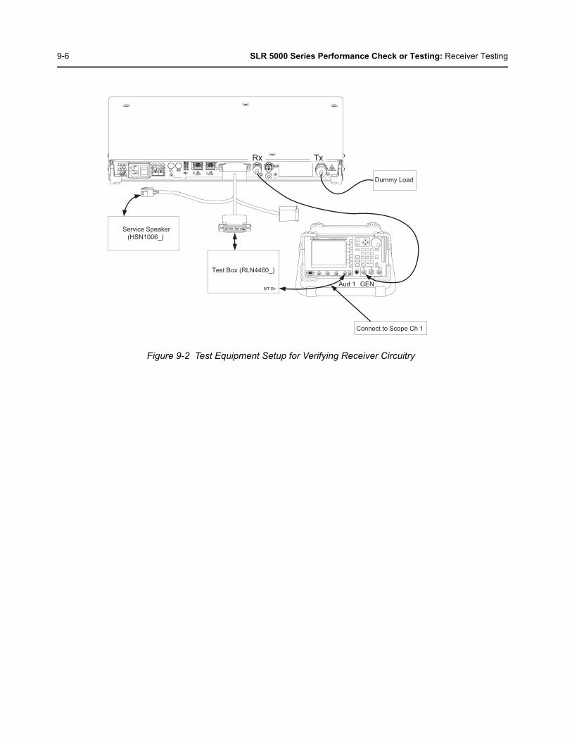
9-6 SLR 5000 Series Performance Check or Testing: Receiver Testing
Figure 9-2 Test Equipment Setup for Verifying Receiver Circuitry
HELPTAB
1
SELECT
CANCEL
IFR 390I Digital Radio Test Set
TEST HOLD
CONFIG
UTILS ENTER
MIC / ACC GEN T/R ANT
RETURN
TEST PORT CH1 SCOPE CH2 1 2AUDIO INFCTN GEN / DEMOD OUT
0 .#
ASSIGN
–*
2
4 5 6
7
HELP
8 9
3
GEN
Test Box (RLN4460_)
Service Speaker (HSN1006_)
Aud 1 MT B+
Dummy Load
TxRx
Connect to Scope Ch 1
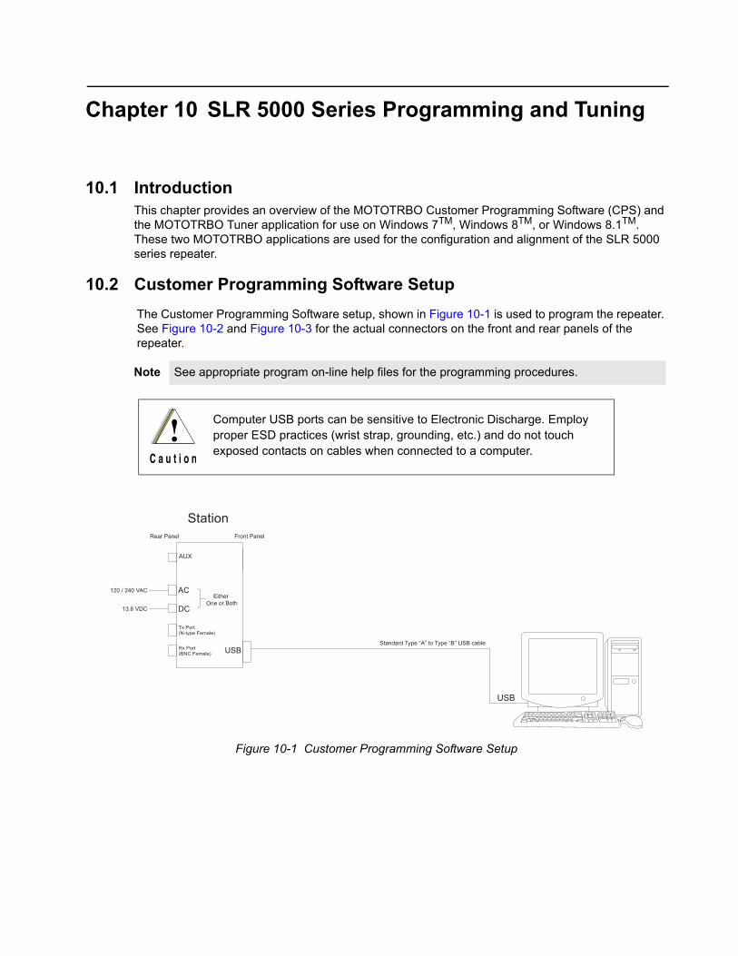
Chapter 10 SLR 5000 Series Programming and Tuning
10.1 IntroductionThis chapter provides an overview of the MOTOTRBO Customer Programming Software (CPS) and the MOTOTRBO Tuner application for use on Windows 7TM, Windows 8TM, or Windows 8.1TM. These two MOTOTRBO applications are used for the configuration and alignment of the SLR 5000 series repeater.
10.2 Customer Programming Software Setup
The Customer Programming Software setup, shown in Figure 10-1 is used to program the repeater. See Figure 10-2 and Figure 10-3 for the actual connectors on the front and rear panels of the repeater.
Note See appropriate program on-line help files for the programming procedures.
Computer USB ports can be sensitive to Electronic Discharge. Employ proper ESD practices (wrist strap, grounding, etc.) and do not touch exposed contacts on cables when connected to a computer.
Figure 10-1 Customer Programming Software Setup
Front Panel
USB
AC
USB
120 / 240 VAC
Station
Tx Port(N-type Female)
Rx Port(BNC Female)
AUX
DC13.6 VDC
Either One or Both
Standard Type “A” to Type “B” USB cable
Rear Panel

10-2 SLR 5000 Series Programming and Tuning: Reference Oscillator Alignment
Figure 10-2 Front view of SLR 5000 Series Repeater
Figure 10-3 Rear view of SLR 5000 Series Repeater
10.3 Reference Oscillator AlignmentThis feature is used to adjust the reference oscillator of the repeater. This alignment process should be done as maintenance schedules and regulations require or if the Modem FRU has been replaced in the repeater.
10.3.1 Tuning Procedure
1. Connect the repeater’s transmitter antenna port to the Communication Analyzer.
2. Power the repeater from either an AC or DC source.
3. Click the “Read” button in the tuner to begin reading the repeater’s tuning softpot values.
4. Select “Ref Oscillator’ under the TX menu in the tree view (See Figure 10-4).
USB Port
AC Inlet Connector DC Inlet Connector Aux Connector Rx RF Connector Tx RF Connector

SLR 5000 Series Programming and Tuning: Repeater Tuning Setup 10-3
Figure 10-4 Tx Menu Tree (Ref. Oscillator)
5. Configure the current operating frequency into the Communications Analyzer.
6. Click the “PTT Toggle” button to key up the repeater.
7. Adjust the working softpot value until the frequency is within the performance specifications (+/- 40 Hz for UHF and VHF) from the frequency point.
8. Click the “PTT Toggle” button to de-key the repeater.
9. Click the “Write” button to save the tuned softpot value into the repeater codeplug.
10.4 Repeater Tuning Setup
A personal computer (PC), Windows TM operating system, and the MOTOTRBO Tuner application are required to align the repeater. To perform the tuning procedures, the repeater must be connected to the PC and test equipment setup as shown in Figure 10-5.
Figure 10-5 SLR 5000 Series Repeater Tuning Equipment Setup
TransmitService Monitor
or Counter
Wattmeter20 dB Pad
Front Panel
AC
USB
120 / 240 VAC
Station
Tx Port(BNC Female)
AUX
DC13.6 VDCEither
One or Both
Rear Panel
Standard Type “A” to Type “B” USB cable
USB

10-4 SLR 5000 Series Programming and Tuning: Rx Audio Level Set
10.5 Rx Audio Level SetThe procedure outlined in this section is used to set the receive output audio level from the repeater for a given RF deviation of the received RF signal. Perform this procedure any time the Rx audio level needs adjustment.
10.5.1 Tuning Procedure
1. Connect the repeater’s receiver antenna port to the Communication Analyzer.
2. Power the repeater from either an AC or DC source.
3. Launch the Tuner application and click the “Read” button to read the softpot values.
4. Select “Rx Rated Volume” under the Rx menu in the tree view (See Figure 10-6).
Figure 10-6 Rx Menu tree (Rx Rated Volume)
5. Set the Communication Analyzer to output a -47 dBm RF signal modulated with a 1 kHz tone at 60% of full deviation on the tuning frequency. The tuning frequency is the value displayed on the Tuner GUI under the heading of “Frequency Points”.
6. Adjust the softpot value until the desired receive audio level is achieved at pin #7 (in reference to ground) on the Aux connector. Ground connections provided by the Aux connector are pins: 9, 16, 17, 18, and 19.
Note The Tuner aligns this parameter in a 12.5 kHz channel spacing, so 60% is 1.5 kHz of deviation. If the CPS is set for 25 kHz operation, the repeater will automatically scale the deviation by a factor of two when it is outside the Tuner environment.
Note Programmed TPL and DPL squelch requirements are automatically disabled for the tuning frequency while in the Tuner environment.
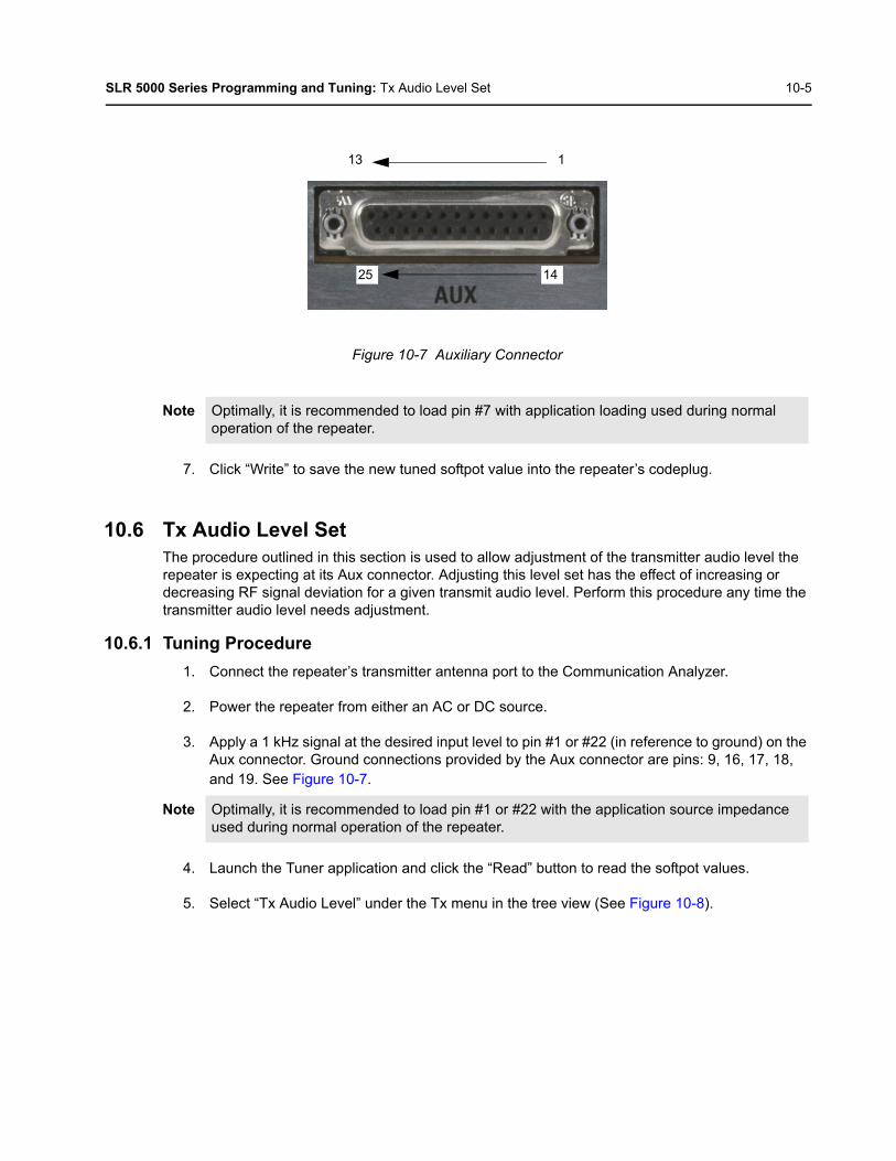
SLR 5000 Series Programming and Tuning: Tx Audio Level Set 10-5
Figure 10-7 Auxiliary Connector
7. Click “Write” to save the new tuned softpot value into the repeater’s codeplug.
10.6 Tx Audio Level SetThe procedure outlined in this section is used to allow adjustment of the transmitter audio level the repeater is expecting at its Aux connector. Adjusting this level set has the effect of increasing or decreasing RF signal deviation for a given transmit audio level. Perform this procedure any time the transmitter audio level needs adjustment.
10.6.1 Tuning Procedure
1. Connect the repeater’s transmitter antenna port to the Communication Analyzer.
2. Power the repeater from either an AC or DC source.
3. Apply a 1 kHz signal at the desired input level to pin #1 or #22 (in reference to ground) on the Aux connector. Ground connections provided by the Aux connector are pins: 9, 16, 17, 18, and 19. See Figure 10-7.
4. Launch the Tuner application and click the “Read” button to read the softpot values.
5. Select “Tx Audio Level” under the Tx menu in the tree view (See Figure 10-8).
Note Optimally, it is recommended to load pin #7 with application loading used during normal operation of the repeater.
Note Optimally, it is recommended to load pin #1 or #22 with the application source impedance used during normal operation of the repeater.
13 1
1425

10-6 SLR 5000 Series Programming and Tuning: Tx Audio Level Set
Figure 10-8 Tx Menu Tree (Tx Audio Level)
6. Enter the tuning frequency into the Communication Analyzer (the value displayed on the Tuner GUI under the heading of “Frequency Points”).
7. Click the “PTT Toggle” button within the Tuner environment to key up the repeater.
8. Adjust the softpot value until 60% of the rated system deviation (RSD) is achieved.
9. Click the “PTT Toggle” button within the Tuner environment to de-key the repeater.
10. Click “Write” to save the new tuned softpot value into the repeater’s codeplug.
Note The Tuner aligns this parameter in a 12.5 kHz channel spacing, so 60% is 1.5 kHz of deviation. If the CPS is set for 25 kHz operation, the repeater will automatically scale the deviation by a factor of two when it is outside the Tuner environment.

SLR 5000 Series Programming and Tuning: Modulation Limit Alignment 10-7
10.7 Modulation Limit Alignment This feature is to set the modulation limit of the SLR 5000 Series Repeater.
10.7.1 Tuning Procedure (with no Tx Data and no PL)
1. Connect the repeater’s antenna port to the attenuation pad, if necessary, before connecting to the Communication Analyzer.
2. Power the repeater from either an AC or DC source.
3. Apply a 1 kHz signal at 1.2 Vrms to Pin 1 of the J7 backplane connector.
- Signal ground is Pin 9 of the J7 backplane connector.
4. Launch the Tuner application and click the “Read” button to read the softpot values.
5. Select “Modulation Limit” under the Tx menu in the tree view (See Figure 10-9).
Figure 10-9 Tx Menu tree (Tuning Procedure with no Tx data)
6. Enter the tuning frequency into the Communication Analyzer (the value displayed on the Tuner GUI).
7. Click the “PTT Toggle” button within the Tuner environment to key up the repeater.
8. Adjust the softpot value until the maximum deviation is 92% of the rated system deviation (RSD). This will be tested in a 12.5 kHz channel spacing, so 92% of 2.5 kHz is 2.3 kHz.
9. Click the “PTT Toggle” button within the Tuner environment to de-key the repeater.
10. Click “Write” to save the new tuned softpot value into the repeater’s codeplug.
Note A modulation limit alignment is not needed if the repeater is used in repeat mode. This isalways the case when the repeater is in digital mode.
Note If data or PL signaling is applied to Pin 13 of the J7 connector, proceed to Section 10.7.3.
Note Set the modulation limit to 92% so that any additional deviation incurred by the transmitterVCOs over temperature is compensated for.
Channel Spacing (kHz) RSD (kHz) 92% of RSD (kHz) Tolerance (Hz)
12.5 2.5 2.3 +0/ -50
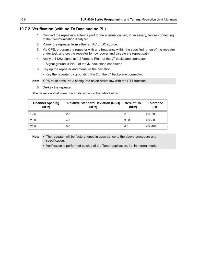
10-8 SLR 5000 Series Programming and Tuning: Modulation Limit Alignment
10.7.2 Verification (with no Tx Data and no PL)
1. Connect the repeater’s antenna port to the attenuation pad, if necessary, before connecting to the Communication Analyzer.
2. Power the repeater from either an AC or DC source.
3. Via CPS, program the repeater with any frequency within the specified range of the repeater under test, and set the repeater for low power and disable the repeat path.
4. Apply a 1 kHz signal at 1.2 Vrms to Pin 1 of the J7 backplane connector.
- Signal ground is Pin 9 of the J7 backplane connector.
5. Key up the repeater and measure the deviation
- Key the repeater by grounding Pin 2 of the J7 backplane connector.
6. De-key the repeater.
The deviation shall meet the limits shown in the table below.
Note CPS must have Pin 2 configured as an active low with the PTT function.
Channel Spacing(kHz)
Relative Standard Deviation (RSD)(kHz)
92% of RS(kHz)
Tolerance(Hz)
12.5 2.5 2.3 +0/ -50
20.0 4.0 3.68 +0/ -80
25.0 5.0 4.6 +0/ -100
Note • The repeater will be factory-tuned in accordance to the above procedure and specification.
• Verification is performed outside of the Tuner application, i.e. in normal mode.

SLR 5000 Series Programming and Tuning: Modulation Limit Alignment 10-9
10.7.3 Tuning Procedure (with Tx Data or PL)
1. Connect the repeater’s antenna port to the attenuation pad, if necessary, before connecting to the Communication Analyzer.
2. Turn on the repeater using an AC or DC source.
3. Click the “Read” button on the Tuner application to read the repeater’s softpot values.
4. Select “Modulation Limit” under the Tx menu in the tree view.
5. Enter the tuning frequency into the Communication Analyzer (the value displayed by the Tuner application).
6. Click the “PTT Toggle” button within the Tuner environment to key up the repeater.
7. Apply a 1 kHz signal at 1.2Vrms to Pin 22 of the J7 backplane connector.
- Signal ground is Pin 9 of the J7 backplane connector.
- If the manufacturer of the third party controller specifies that the Tx Audio is not to be pre-emphasized, use Pin 1 instead of Pin 22.
8. Adjust the Modulation Limit softpot to a value that limits the maximum deviation to “X”% RSD, where “X” is equal to “92% RSD” minus “Tx Data’s % RSD”.
E.g. If Tx Data deviation is equal to 17%,
X = 92% - 17% = 75% as the maximum deviation limit.
Figure 10-10 Example of maximum deviation limit calculation
9. Click the “PTT Toggle” button within the Tuner environment to de-key the repeater.
10. Click “Write” to save the newly tuned softpot value into the repeater’s codeplug.
11. Alignment is complete.
Note See Figure 3-3 for details regarding the audio and data flow.
Note Set the modulation limit to 92% to compensate for any additional deviation incurred by thetransmitter VCOs over temperature.
Note The Tuner application always aligns the Modulation Limit parameter in a 12.5 kHz channelspacing regardless of the CPS setting, so calculate the tuning % RSD accordingly. If theCPS is set for 25 kHz operation, the repeater will automatically scale the deviation by afactor of two when outside of the Tuner environment.
8%
17%
75%
100%
0%
%RSD 92%
With Tx Data or PL
Buffer
Data or PL
Voice

10-10 SLR 5000 Series Programming and Tuning: Modulation Limit Alignment
10.7.4 Verification (with Tx Data or PL)
See Section 10.7.2 with the following exceptions:
• The same Tx data signal level determined (obtained from Step 8 in Section 10.7.3), is applied to Pin 13 during the validation process.
• Pin 22 may be used instead of Pin 1, depending on the recommendation by the manufacturer of the third party controller.

Chapter 11 SLR 5000 Series Maintenance and Disassembly/Reassembly
11.1 Introduction
This chapter provides details about the following:
• Routine maintenance
• Preventive maintenance (inspection and cleaning)
• Safe handling of CMOS and LDMOS devices
• Disassembly and reassembly of the repeater
• Repair procedures and techniques.
11.2 Routine Maintenance
The repeater and ancillary equipment have been designed with state-of-the-art technology and operate under software control, thus requiring minimal routine maintenance. Virtually all repeater operating parameters are monitored and self-corrected by the Modem and the firmware it runs, which makes adjustments and tuning virtually unnecessary.
Provided that the equipment is installed in an area which meets the specified environmental requirements, the only routine maintenance task required is the calibration of the repeater reference oscillator circuit.
11.3 Preventive MaintenancePeriodic visual inspection and cleaning is recommended.
11.3.1 Inspection
Check that the external surfaces of the repeater are clean, and that all external controls and connections are in order. It is not recommended to inspect the interior electronic circuitry.
11.3.2 Cleaning Procedures
The following procedures describe the recommended cleaning agents and the methods to be used when cleaning the external and internal surfaces of the repeater. External surfaces include the top cover and repeater enclosure.
Periodically clean smudges and grime from exterior enclosure. Use a soft, non-abrasive cloth moistened in a 0.5% solution of mild dishwashing detergent and water solution. Rinse the surface using a second cloth moistened in clean water, and clean any dirt or debris from the fan grill and louvers on the front side.
Note It is recommended that the repeater is cleaned with a soft dry cloth while in service.

11-2 SLR 5000 Series Maintenance and Disassembly/Reassembly: Safe Handling of CMOS and LDMOS Devices
The only factory recommended liquid for cleaning the printed circuit boards and their components is isopropyl alcohol (100% by volume).
Cleaning Internal Circuit Boards and Components
Isopropyl alcohol (100%) may be applied with a stiff, non-metallic, short-bristled brush to dislodge embedded or caked materials located in hard-to-reach areas. The brush stroke should direct the dislodged material out and away from the inside of the repeater. Make sure that controls or tunable components are not soaked with alcohol. Do not use high-pressure air to hasten the drying process since this could cause the liquid to collect in unwanted places. Once the cleaning process is complete, use a soft, absorbent, lintless cloth to dry the area. Do not brush or apply any isopropyl alcohol to the top cover and repeater enclosure.
11.4 Safe Handling of CMOS and LDMOS DevicesComplementary metal-oxide semiconductor (CMOS) and laterally diffused metal-oxide semiconductor (LDMOS) devices are used in this family of stations, and are susceptible to damage by electrostatic or high voltage charges. Damage can be latent, resulting in failures occurring weeks or months later. Therefore, special precautions must be taken to prevent device damage during disassembly, troubleshooting, and repair.
Handling precautions are mandatory for CMOS/ LDMOS circuits and are especially important in low humidity conditions.
Note Internal surfaces should be cleaned only when the repeater is disassembled for service orrepair.
Note Always use a fresh supply of alcohol and a clean container to prevent contamination by dissolved material (from previous usage).

SLR 5000 Series Maintenance and Disassembly/Reassembly: Safe Handling of CMOS and LDMOS Devices 11-3
DO NOT attempt to disassemble the repeater without first referring to the following CAUTION statement.
This repeater contains static-sensitive devices. Do not open the repeater unless you are properly grounded. Take the following precautions when working on this unit:
• Store and transport all CMOS/ LDMOS devices in conductive material so that all exposed leads are shorted together. Do not insert CMOS/LDMOS devices into conventional plastic “snow” trays used for storage and transportation of other semiconductor devices.
• Ground the working surface of the service bench to protect the CMOS/LDMOS device. We recommend using the Motorola Static Protection Assembly (part number 0180386A82), which includes a wrist strap, two ground cords, a table mat, and a floor mat, ESD shoes and an ESD chair.
• Wear a conductive wrist strap in series with a 100k resistor to ground. (Replacement wrist straps that connect to the bench top covering are Motorola part number 4280385A59).
• Do not wear nylon clothing while handling CMOS /LDMOS devices.
• Do not insert or remove CMOS/ LDMOS devices with power applied. Check all power supplies used for testing CMOS/LDMOS devices to be certain that there are no voltage transients present.
• When straightening CMOS/ LDMOS pins, provide ground straps for the apparatus used.
• When soldering, use a grounded soldering iron.
• If at all possible, handle CMOS/ LDMOS devices by the package and not by the leads. Prior to touching the unit, touch an electrical ground to remove any static charge that you may have accumulated. The package and substrate may be electrically common. If so, the reaction of a discharge to the case would cause the same damage as touching the leads.
C a u t i o n

11-4 SLR 5000 Series Maintenance and Disassembly/Reassembly: Disassembly
11.5 Disassembly
11.5.1 Disassembly – General
Station modules suspected of being faulty must be replaced with known good modules to restore the repeater to proper operation. The following are typical procedures to remove each of the repeater modules.
1. Power cord (and battery backup power, if used) and all external cables must be disconnected before opening up repeater. Label each removed cable as required to ensure it is properly reconnected.
2. Take the proper grounding precautions as stated in Section 11.4 on page 11-2.
3. When disassembling repeater, retain all screws for reuse.
The following tools are required for disassembling and reassembling the repeater:
• Torque Drivers (T10, T20 and T30). See Section 11.9 on page 11-24 for the different size fasteners of screw torques.
• Hex Nut Drivers (16 mm, ¾ inch [19 mm])
• Needle Nose Pliers (optional)
• Torque Gauge capable of measuring torque up to 20 in-lb (2.3 N-m) within +/- 1 in-lb (0.1 N-m)
If a unit requires more complete testing or service than is customarily performed at the basic level, send the repeater or FRU to a Motorola Service Center.
The following disassembly procedures should be performed only if necessary.
11.5.2 Disassembly – Detailed
11.5.2.1 Protective Cover Disassembly
1. Remove the six screws on the Bottom Cover with a T10 Torx driver.
2. Detach the Bottom Cover.
3. Remove the six screws on the Top Cover with a T10 Torx driver.
4. Detach the Top Cover.
11.5.2.2 Front Housing Disassembly
1. Remove the three screws securing the Front Housing to the repeater chassis with a T10 Torxdriver.
2. Slightly lift the Repeater and rock the Front Housing away from the chassis.

SLR 5000 Series Maintenance and Disassembly/Reassembly: Disassembly 11-5
Figure 11-1 Removing Front Housing from Repeater
11.5.2.3 Cable Disassembly
1. Disengage cable connecting Modem to Chassis ID module.
2. Remove the flex cables connecting the Modem to the Power Amplifier Module and Front Panel.
3. Remove the coaxial able connecting the Modem to the Power Amplifier Module.
4. Gently press the locking clip and pull the “C5” connector from the Modem.
5. Remove the screws from the three cable clamps securing the cables from the power supply to the fans and modules with a T20 Torx driver and remove the cable clamps from repeater.
6. Remove the two DC power screws from the Power Amplifier Module with a T10 Torx driver.
7. Remove the two DC power screws from the Modem with a T10 Torx driver.
8. Disengage the three connectors from the Power Supply to the three mounted fans with needle nose pliers or fingers.
Note When disengaging flexible cables, pull parallel to the insertion direction of the cable to avoiddamaging the cables.
DO NOT attempt to remove the Chassis ID module as removing it will void the warranty as well as disabling any purchased software features. Keep the Chassis ID module installed throughout disassembly. C a u t i o n

11-6 SLR 5000 Series Maintenance and Disassembly/Reassembly: Disassembly
Figure 11-2 Removing Cables
11.5.2.4 Fan Disassembly
1. Press the tab below the fan module until it disengages. See Figure 11-3 for location of tab.
2. Rock the fan module up and away from the frame and remove.
3. Repeat the steps above for the remaining two fan modules.
Figure 11-3 Removing Fan
3
1
2
4
56
7
8

SLR 5000 Series Maintenance and Disassembly/Reassembly: Disassembly 11-7
11.5.2.5 Front Panel Disassembly
1. Using a T10 Torx driver, remove the three screws securing the front panel to the repeater chassis.
2. Remove the Front Panel PCB from the repeater.
Figure 11-4 Removing Front Panel
11.5.2.6 Power Supply Removal
1. Remove the four screws securing the Power Supply Module to the repeater chassis with a T20 Torx driver.
Figure 11-5 Removing Power Supply Module from Repeater
2. Remove the Power Supply Module from the repeater.
Note Ensure all connections from Power Supply to various parts of the repeater have been detached.
12 3

11-8 SLR 5000 Series Maintenance and Disassembly/Reassembly: Disassembly
11.5.2.7 Modem Removal
1. Detach the two coaxial cables connecting the RX Input and Reference (REF) Input connectors to the Modem.
2. Remove the four screws holding the Modem to the repeater chassis with a T20 Torx driver.
Figure 11-6 Removing Modem
3. Remove the Modem from the repeater.
Note Ensure all connections from Power Supply to various parts of the repeater have been detached.

SLR 5000 Series Maintenance and Disassembly/Reassembly: Disassembly 11-9
11.5.2.8 Power Amplifier Module Removal
1. Remove the nut securing the N-Type connector to the back panel on the Power Amplifier with a ¾ inch (19 mm) hex nut driver.
2. Remove the accompanying lock washer.
3. Remove the four screws securing the Power Amplifier Module to the Repeater chassis with a T20 Torx driver.
Figure 11-7 Removing Power Amplifier Module
4. Remove the Power Amplifier Module from the Repeater.
Note Ensure all connections from Power Supply to various parts of the repeater have been detached.

11-10 SLR 5000 Series Maintenance and Disassembly/Reassembly: Disassembly
11.5.2.9 Back Panel Removal
1. Remove the two nuts securing the RX and Reference (REF) BNC cables to the back panel with a 16 mm hex nut driver.
2. Remove the two corresponding lock washers.
3. Remove the two cables.
Figure 11-8 Removing Rx and REF BNC Cables
4. Remove the ground screw located below the REF connector with a T30 Torx driver.
Figure 11-9 Removing Ground Screw
5. Remove the five screws securing the back panel to the repeater chassis with a T10 Torx driver.
6. Remove the back panel from the repeater.
7. Remove the two rubber plugs from the back panel.
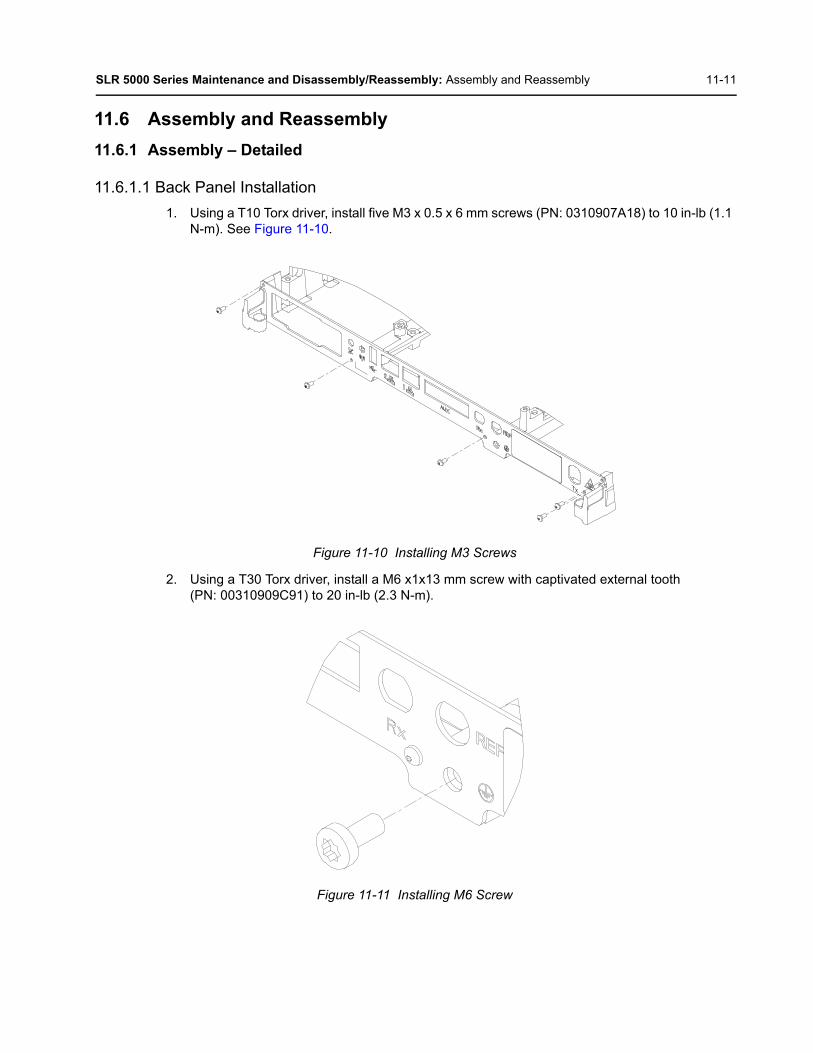
SLR 5000 Series Maintenance and Disassembly/Reassembly: Assembly and Reassembly 11-11
11.6 Assembly and Reassembly
11.6.1 Assembly – Detailed
11.6.1.1 Back Panel Installation
1. Using a T10 Torx driver, install five M3 x 0.5 x 6 mm screws (PN: 0310907A18) to 10 in-lb (1.1 N-m). See Figure 11-10.
Figure 11-10 Installing M3 Screws
2. Using a T30 Torx driver, install a M6 x1x13 mm screw with captivated external tooth (PN: 00310909C91) to 20 in-lb (2.3 N-m).
Figure 11-11 Installing M6 Screw

11-12 SLR 5000 Series Maintenance and Disassembly/Reassembly: Assembly and Reassembly
11.6.1.2 Input Cable Installation
1. Insert the RX (PN: 30012083001) and Reference (PN: CB000024A01) cables into corresponding holes in back panel.
Figure 11-12 Installing Rx and Reference Cables
2. Assemble the corresponding lock washers onto the connectors. Using a 16 mm hex nut driver, tighten the 16 mm hex nuts to 15 in-lb (1.7 N-m) on both connectors.
Figure 11-13 Assembling Lock Washers onto Connectors
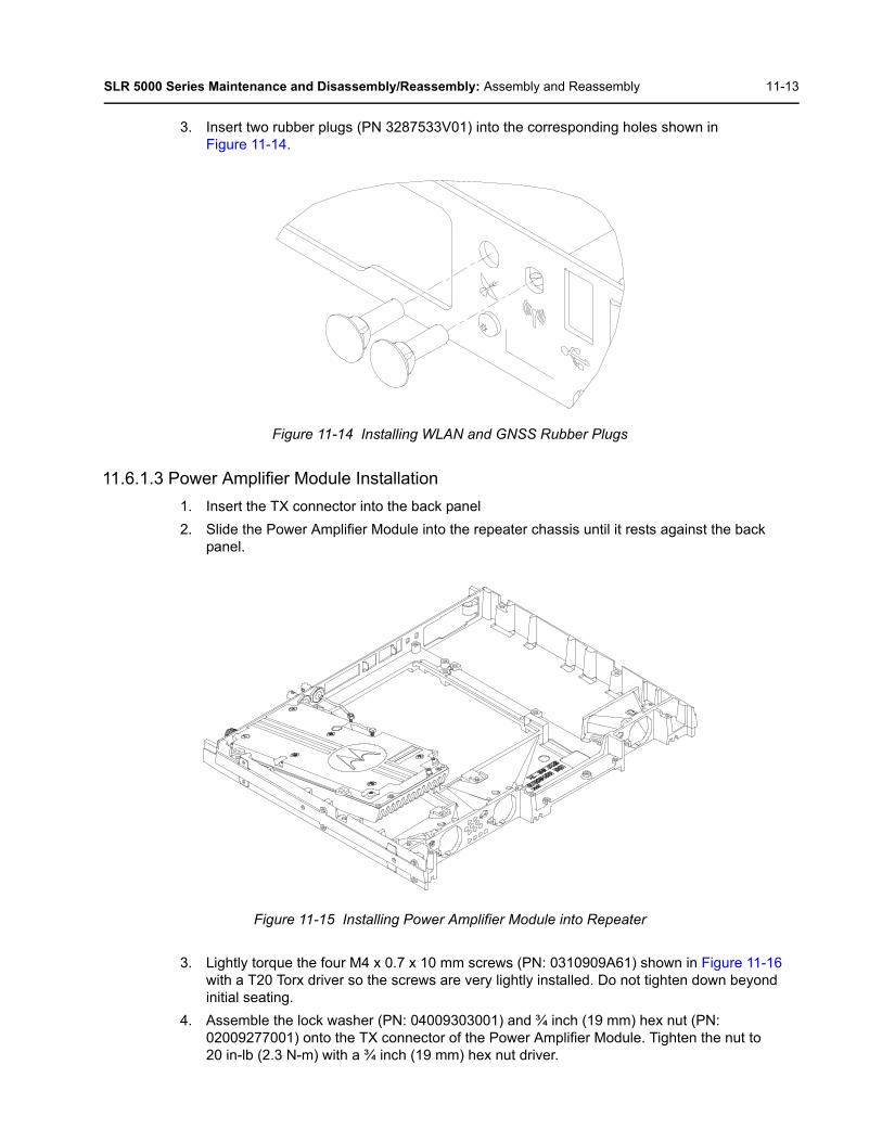
SLR 5000 Series Maintenance and Disassembly/Reassembly: Assembly and Reassembly 11-13
3. Insert two rubber plugs (PN 3287533V01) into the corresponding holes shown in Figure 11-14.
Figure 11-14 Installing WLAN and GNSS Rubber Plugs
11.6.1.3 Power Amplifier Module Installation
1. Insert the TX connector into the back panel
2. Slide the Power Amplifier Module into the repeater chassis until it rests against the back panel.
Figure 11-15 Installing Power Amplifier Module into Repeater
3. Lightly torque the four M4 x 0.7 x 10 mm screws (PN: 0310909A61) shown in Figure 11-16 with a T20 Torx driver so the screws are very lightly installed. Do not tighten down beyond initial seating.
4. Assemble the lock washer (PN: 04009303001) and ¾ inch (19 mm) hex nut (PN: 02009277001) onto the TX connector of the Power Amplifier Module. Tighten the nut to 20 in-lb (2.3 N-m) with a ¾ inch (19 mm) hex nut driver.

11-14 SLR 5000 Series Maintenance and Disassembly/Reassembly: Assembly and Reassembly
5. Tighten the four M4 x 0.7 x 10 mm screws (PN: 0310909A61) to 15 in-lb (1.7 N-m) with a T20 Torx driver to secure the Power Amplifier Module to the repeater chassis.
Figure 11-16 Securing Power Amplifier Module to Repeater Chassis
11.6.1.4 Modem Installation
1. Lift the RX and Reference (REF) cables and slide the Modem all the way to the back panel. Make sure the mounting ears on the Modem line up with the screw holes on the repeater chassis.
2. Tighten the four M4 x 0.7 x 10 mm screws (PN: 0310909A61) to 15 in-lb (1.7 N-m) using a T20 Torx driver to secure the Modem to the repeater chassis.
Figure 11-17 Securing Modem to Repeater Frame
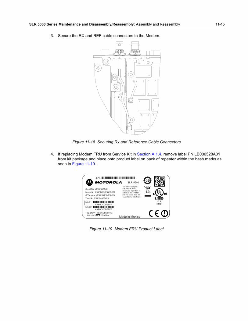
SLR 5000 Series Maintenance and Disassembly/Reassembly: Assembly and Reassembly 11-15
3. Secure the RX and REF cable connectors to the Modem.
Figure 11-18 Securing Rx and Reference Cable Connectors
4. If replacing Modem FRU from Service Kit in Section A.1.4, remove label PN LB000528A01 from kit package and place onto product label on back of repeater within the hash marks as seen in Figure 11-19.
Figure 11-19 Modem FRU Product Label
SN:
Made in Mexico
Serial No: XXXXXXXXXModel No: XXXXXXXXXXXXXXS/Tanapa: XXXXXXXXXXXXXXType No: XXXXX-XXXXX
100-240V ~ Max 4A 50/60 Hz11.0-14.4V 17A Max
I.T.E.31 NH
This device complies with Part 15 of the FCC rules. Operation is subject to the condition that this device does not cause harmful interference
SLR 5500
MAC 1: AABBCCDDEEFF
MAC 2: AABBCCDDEEFF
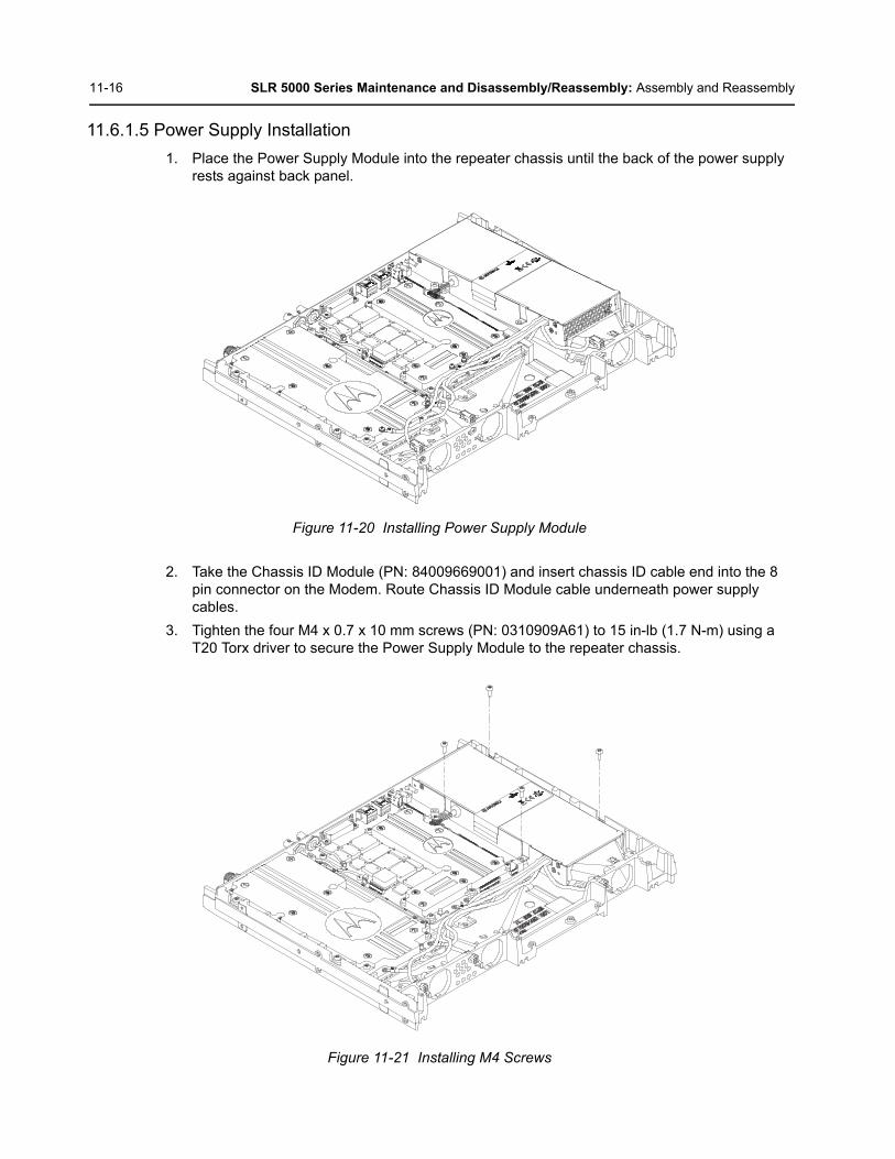
11-16 SLR 5000 Series Maintenance and Disassembly/Reassembly: Assembly and Reassembly
11.6.1.5 Power Supply Installation
1. Place the Power Supply Module into the repeater chassis until the back of the power supply rests against back panel.
Figure 11-20 Installing Power Supply Module
2. Take the Chassis ID Module (PN: 84009669001) and insert chassis ID cable end into the 8 pin connector on the Modem. Route Chassis ID Module cable underneath power supply cables.
3. Tighten the four M4 x 0.7 x 10 mm screws (PN: 0310909A61) to 15 in-lb (1.7 N-m) using a T20 Torx driver to secure the Power Supply Module to the repeater chassis.
Figure 11-21 Installing M4 Screws

SLR 5000 Series Maintenance and Disassembly/Reassembly: Assembly and Reassembly 11-17
4. Snap the fan jumper cables into the chassis for the Power Supply, Modem, and Power Amplifier fans.
Figure 11-22 Snapping Fan Cable

11-18 SLR 5000 Series Maintenance and Disassembly/Reassembly: Assembly and Reassembly
11.6.1.6 Fan Installation
1. Orient the fan module so that the cables are out at the lower left. See Figure 11-23.
2. Rest the bottom tab of the mounting bracket onto the main frame opening with proper orientation.
3. Push the fan assembly towards the main frame until both tabs are fully snapped and engaged. Two audible snaps should be heard.
4. Repeat the steps above for the remaining two fans
Figure 11-23 Installing Fan
5. Connect the three fan cables to their corresponding jumper cables.
11.6.1.7 Front Panel Installation
1. Place the Front Panel (Kit Number: PMLN6490A) onto the corresponding bosses on the repeater frame.
2. Install the three M3 x 0.5 x 6 mm screws (PN: 0310907A18) to 10 in-lb (1.1 N-m) in the order shown in Figure 11-24 using a T10 Torx driver.
Figure 11-24 Installing Front Panel
Note For each of the fans, look inside the fan shroud to ensure both the top and bottom fan mounting bracket tabs are fully engaged with the protrusions (teeth) of the base frame.
12 3
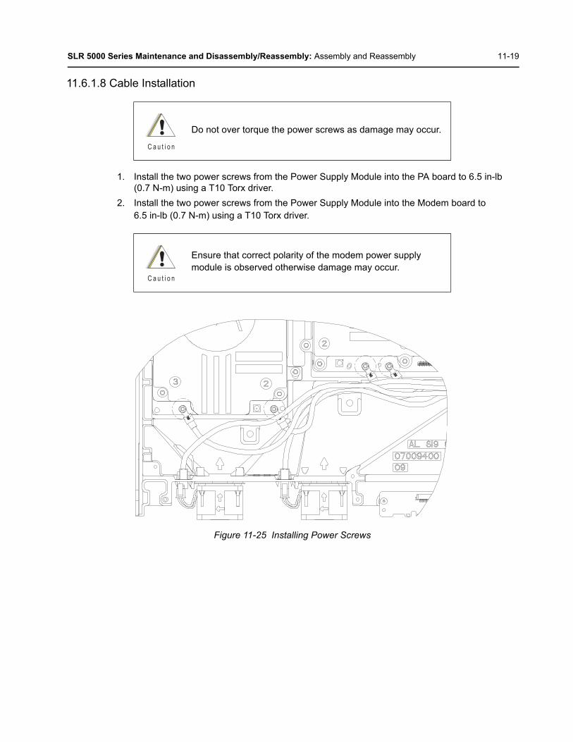
SLR 5000 Series Maintenance and Disassembly/Reassembly: Assembly and Reassembly 11-19
11.6.1.8 Cable Installation
1. Install the two power screws from the Power Supply Module into the PA board to 6.5 in-lb (0.7 N-m) using a T10 Torx driver.
2. Install the two power screws from the Power Supply Module into the Modem board to 6.5 in-lb (0.7 N-m) using a T10 Torx driver.
Figure 11-25 Installing Power Screws
Do not over torque the power screws as damage may occur.
Ensure that correct polarity of the modem power supply module is observed otherwise damage may occur.
C a u t i o n
C a u t i o n

11-20 SLR 5000 Series Maintenance and Disassembly/Reassembly: Assembly and Reassembly
3. Secure the “C3” cable from the Power Supply Module to the chassis in the pocket near the Power Supply Module using a cable clamp (PN: 42009306001) and a M4 x 0.7 x 10 mm screw (PN: 0310909A61) torque to 15 in-lb (1.7 N-m) using a T20 Torx driver.
Figure 11-26 Securing Cables
4. Secure the “C2”, “C4” and “C6” cables from the Power Supply Module to the chassis near the Modem using a cable clamp (PN: 42009306002) and a M4 x 0.7 x 10 mm screw (PN: 0310909A61) torque to 15 in-lb (1.7 N-m) using a T20 Torx driver.
5. Secure the “C6” cable from the Power Supply Module to the chassis near the PA Module using a cable clamp (PN: 42009306001) and a M4 x 0.7 x 10 mm screw (PN: 0310909A61) torque to 15 in-lb (1.7 N-m) using a T20 Torx driver.
6. Secure the connector of the “C5” cable between the Power Supply Module and the Modem to the corresponding Modem Connector.
7. Assemble the coaxial cable (PN: 30012084001) to the connectors on the Modem and PA Module
8. Assemble the flex cable (PN: 30012085001) between the PA Module and the Modem. Install the PA Module side first.
9. Assemble the flex cable (PN: 84007002001) between the Modem and the Front Panel.
Note When installing the flexible cables, directly insert the cable parallel to the connector to avoiddamage to the connector. Do not assemble at angle.
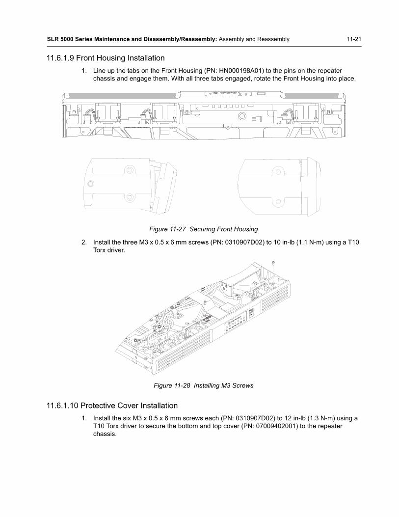
SLR 5000 Series Maintenance and Disassembly/Reassembly: Assembly and Reassembly 11-21
11.6.1.9 Front Housing Installation
1. Line up the tabs on the Front Housing (PN: HN000198A01) to the pins on the repeater chassis and engage them. With all three tabs engaged, rotate the Front Housing into place.
Figure 11-27 Securing Front Housing
2. Install the three M3 x 0.5 x 6 mm screws (PN: 0310907D02) to 10 in-lb (1.1 N-m) using a T10 Torx driver.
Figure 11-28 Installing M3 Screws
11.6.1.10 Protective Cover Installation
1. Install the six M3 x 0.5 x 6 mm screws each (PN: 0310907D02) to 12 in-lb (1.3 N-m) using a T10 Torx driver to secure the bottom and top cover (PN: 07009402001) to the repeater chassis.

11-22 SLR 5000 Series Maintenance and Disassembly/Reassembly: Exploded Mechanical View
11.7 Exploded Mechanical View
Figure 11-29 SLR 5000 Series Assembly Exploded View
12
3
4
5
6
7
8
9
1110
19
1218
15
1617
24
23
20
13
14
22
21
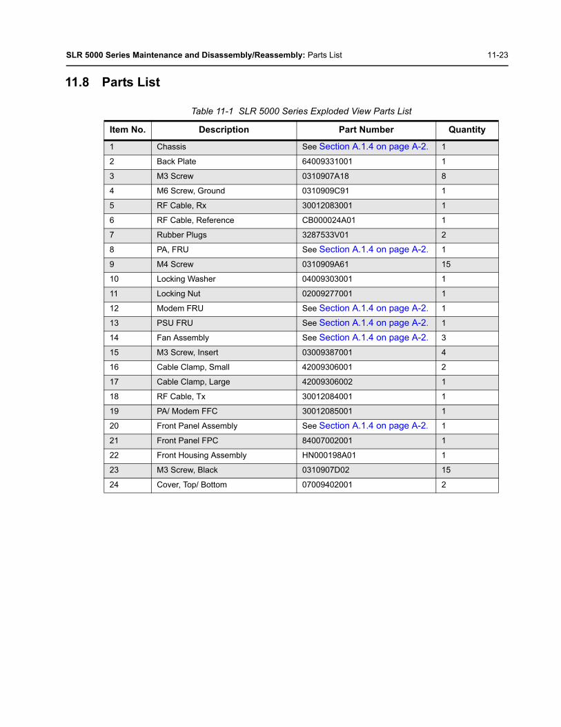
SLR 5000 Series Maintenance and Disassembly/Reassembly: Parts List 11-23
11.8 Parts List
Table 11-1 SLR 5000 Series Exploded View Parts List
Item No. Description Part Number Quantity
1 Chassis See Section A.1.4 on page A-2. 1
2 Back Plate 64009331001 1
3 M3 Screw 0310907A18 8
4 M6 Screw, Ground 0310909C91 1
5 RF Cable, Rx 30012083001 1
6 RF Cable, Reference CB000024A01 1
7 Rubber Plugs 3287533V01 2
8 PA, FRU See Section A.1.4 on page A-2. 1
9 M4 Screw 0310909A61 15
10 Locking Washer 04009303001 1
11 Locking Nut 02009277001 1
12 Modem FRU See Section A.1.4 on page A-2. 1
13 PSU FRU See Section A.1.4 on page A-2. 1
14 Fan Assembly See Section A.1.4 on page A-2. 3
15 M3 Screw, Insert 03009387001 4
16 Cable Clamp, Small 42009306001 2
17 Cable Clamp, Large 42009306002 1
18 RF Cable, Tx 30012084001 1
19 PA/ Modem FFC 30012085001 1
20 Front Panel Assembly See Section A.1.4 on page A-2. 1
21 Front Panel FPC 84007002001 1
22 Front Housing Assembly HN000198A01 1
23 M3 Screw, Black 0310907D02 15
24 Cover, Top/ Bottom 07009402001 2
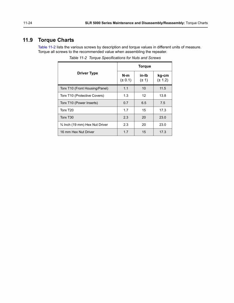
11-24 SLR 5000 Series Maintenance and Disassembly/Reassembly: Torque Charts
11.9 Torque ChartsTable 11-2 lists the various screws by description and torque values in different units of measure. Torque all screws to the recommended value when assembling the repeater.
Table 11-2 Torque Specifications for Nuts and Screws
Driver Type
Torque
N-m(± 0.1)
in-lb(± 1)
kg-cm(± 1.2)
Torx T10 (Front Housing/Panel) 1.1 10 11.5
Torx T10 (Protective Covers) 1.3 12 13.8
Torx T10 (Power Inserts) 0.7 6.5 7.5
Torx T20 1.7 15 17.3
Torx T30 2.3 20 23.0
¾ Inch (19 mm) Hex Nut Driver 2.3 20 23.0
16 mm Hex Nut Driver 1.7 15 17.3

Chapter 12 SLR 5000 Series Installation
12.1 Pre-Installation ConsiderationsProper installation ensures the best possible performance and reliability of the repeater. Pre-installation planning is required. This includes considering the mounting location of the equipment in relation to input power, antennas, and system interfaces. Also to be considered are site environment conditions, the particular mounting method (several available), and required tools and equipment.
It is highly recommended that to read the following before installing this type of equipment for the first time:
• this entire installation section before beginning the actual installation, and
• the Motorola Quality Standard Fixed Network Equipment Installation manual, R56, specifically refer to the information on ground connection for lightning protection.
12.1.1 Installation Overview
The following information is an overview for installing the repeater and ancillary equipment. Step-by-step procedures for each of the major installation tasks are then provided beginning in Section 12.2: "Mechanical Installation" on page 12-9.
• Plan the installation, paying particular attention to environmental conditions at the site, ventilation requirements, and grounding and lightning protection.
• Unpack and inspect the equipment.
• Mechanically install the equipment at the site.
• Make necessary electrical and cabling connections, including the following:
- AC input cabling
- Coaxial cables to transmit and receive antennas
- System cables
• Perform a post-installation function checkout test of the equipment to verify proper installation. Proceed to the Optimization procedures to customize the repeater parameters per customer specifications (e.g., operating frequency, PL, codes, etc.)

12-2 SLR 5000 Series Installation: Pre-Installation Considerations
12.1.2 Site Environmental Conditions
The repeater may be installed in a suitable, restricted access, indoor enclosure in any location suitable for electronic communications equipment, provided that the environmental conditions do not exceed the equipment specifications for temperature, humidity and air quality.
These are:
• Operating Temperature Range
-30 °C (-22 °F) to +60 °C (+140 °F)
This is the temperature measured in close proximity to the repeater. For example, if the repeater is mounted in a cabinet, the temperature within the cabinet is measured.
• Humidity
Repeater to be kept at or below RH of 95%, non-condensing at 50 °C (122 °F).
• Air Quality
For equipment operating in an environmentally controlled environment with the repeater(s) rack mounted, the airborne particulates level must not exceed 25 µg/m³.
For equipment operating in an area which is not environmentally controlled (repeater(s) cabinet mounted), the airborne particulates level must not exceed 90 µg/m³
12.1.3 Equipment Ventilation
The repeaters are equipped with cooling fans that are used to provide forced convection cooling. When planning the installation, observe the following ventilation guidelines:
12.1.3.1 Mounting the SLR 5000 Series Repeater in a Cabinet
• Cabinets must be equipped with ventilation slots or openings in the front (for air entry) and back or side panels (for air to exit). If several repeaters are installed in a single cabinet, be sure ventilation openings surround each repeater to allow for adequate cooling.
• All cabinets must have at least 15 cm (6 in) of open space between the air vents and any wall or other cabinets. This allows adequate air flow.
• When multiple cabinets (each equipped with several repeaters) are installed in an enclosed area, make sure the temperature within each cabinet does not exceed the recommended/ maximum operating temperature of +60 °C (+140 °F). It may be necessary to have air-conditioning or other climate-control equipment installed to satisfy the environmental requirements.
If the repeater is to be installed in an environment which is unusually dusty or dirty (and so does not meet the air quality requirements), the air used to cool the repeater modules must be treated using appropriate filtering devices. Dust or dirt accumulating on the internal circuit boards and modules is not easily removed, and can cause such malfunctions as overheating and intermittent electrical connections.
C a u t i o n

SLR 5000 Series Installation: Pre-Installation Considerations 12-3
12.1.3.2 Mounting the SLR 5000 Series Repeater in a Rack
Multiple SLR 5000 series repeaters can be mounted in an open rack without degradation of specification.
12.1.4 AC and DC Input Power Requirements
12.1.4.1 AC Input Power Requirements
The repeater is equipped with a switching power supply, and this assembly operates from 100 – 240 VAC at 47 – 63 Hz AC input power. A standard 3-prong line cord is supplied to connect the power supply to the AC source.
It is recommended that a standard 3-wire grounded electrical outlet be used as the AC source.
The outlet must be connected to an AC source capable of supplying a maximum of 500 VA. For a nominal 110/ 120 VAC input, the AC source must supply 5 A (minimum). Per R56, the minimum ampacity of the circuit (and protective breaker) feeding the repeater should be no less than 15A. For a nominal 220/ 240 VAC input, the ampacity requirements can be halved.
12.1.4.2 DC Input Power Requirements
The DC source operates from 11 VDC to 14.4 VDC (17 A max). This DC source must be located in the same building as the repeater, and it must meet the requirements of a SELV circuit. The appropriate DC disconnects and current limiting devices must be chosen and implemented per R56.
12.1.4.3 Ground Connection
The repeater is equipped with a ground screw located on the back panel of the repeater. Figure 7-1 on page 7-1 shows the location of the grounding screw. Connect the ground screw to the site ground point. The size of the wire used for this connection must be 8 AWG minimum.
The mounting of only ONE REPEATER PER CABINET is recommended. More than one repeater per cabinet will result in degradation of thermal specifications at high ambient temperatures.
Appropriate precautions should be taken to ensure that repeater ambient temperature does not exceed +60 °C (+140 °F).
If multiple repeaters are required, AND THERMAL SPECIFICATION DEGRADATION IS ACCEPTABLE, the following is recommended when no cabinet fans are used. Up to three repeaters can be mounted in a 76.2 cm (30 in) or larger cabinet with two rack units of spacing between each repeater. This will result in thermal specification performance of -30 °C (-22 °F) to +40 °C (+104 °F).
The AC socket outlet must be installed near the equipment and must be easily accessible.
C a u t i o n
12-4 SLR 5000 Series Installation: Pre-Installation Considerations
12.1.4.4 Battery Connection
Battery backup interface offers the capability of connecting to battery backup power in the event of an AC power line failure. The battery backup system is connected to the repeater through the DC inlet connector on the rear panel of the repeater. See Figure 7-1 on page 7-1 for the location of the DC inlet connector.
12.1.4.5 RF Antenna Connections
The transmit and receive antenna RF connections are made using two separate connectors. Coax cables from the receive and transmit antennas must be connected to their respective connectors. The position of these connectors is shown in Figure 7-1 on page 7-1, and their respective connector types are noted in Table 7-1 on page 7-1.
12.1.4.6 System Cable Connections
System connections are made through the Aux and/or Ethernet connectors located on the back panel of the repeater. The positions of the Aux and Ethernet connectors are shown in Figure 7-1 on page 7-1.
See Section 7.2.8: "Auxiliary (Aux)" on page 7-6 for a description of the signaling that is supported by the Aux connector.
12.1.5 Equipment Mounting Methods
Repeater may be mounted in a rack or cabinet. It may also be configured as a desk mount or wall mount unit.
Repeater can be mounted:
• In a floor-mount cabinet. Each floor-mount cabinet has front and rear vented doors and has the capacity to hold a minimum of a single repeater (see thermal limitations described under Equipment Ventilation), and required ancillary equipment. The larger cabinets provide additional room for supplementary peripheral equipment.
• In a rack. Open frame racks accept multiple repeaters and ancillary equipment; EIA 48.3 cm (19 inch) rack configuration.
Refer to Motorola Quality Standards Fixed Network Equipment Installation Manual R56, for complete information regarding lightning protection.
The repeater should only be connected to a battery supply that is in accordance with the applicable electrical codes for the end use country; for example, the National Electrical Code ANSI/ NFPA No. 70 in the U.S.
The repeater should only be connected to a battery supply that is in accordance with the applicable electrical codes for the end use country; for example, the National Electrical Code ANSI/NFPA No. 70 in the U.S.

SLR 5000 Series Installation: Pre-Installation Considerations 12-5
12.1.5.1 Floor-Mounted Cabinet
The front, side and top views for all available floor-mount cabinets are shown in Figure 12-1 on page 12-5. See Table 12-1 for the cabinet models and associated description.
Refer to Section 12.1.3: "Equipment Ventilation" on page 12-2 for recommended ventilation clearances. For improved access to the unit, tray slides are available as shown in Table 12-2.
Figure 12-1 Floor Mount Cabinet
Table 12-1 Cabinet Models
Model Description
THN6700 12 inch (30.48 cm) indoor cabinet
THN6701 30 inch (76.2 cm) indoor cabinet
THN6702 46 inch (116.84 cm) indoor cabinet
Table 12-2 Cabinet Slide
Model Description
THN6788 Slides Motorola Cabinet
Ensure that the cabinet is securely anchored to the floor, thereby avoiding possible equipment tipping and personal injury.
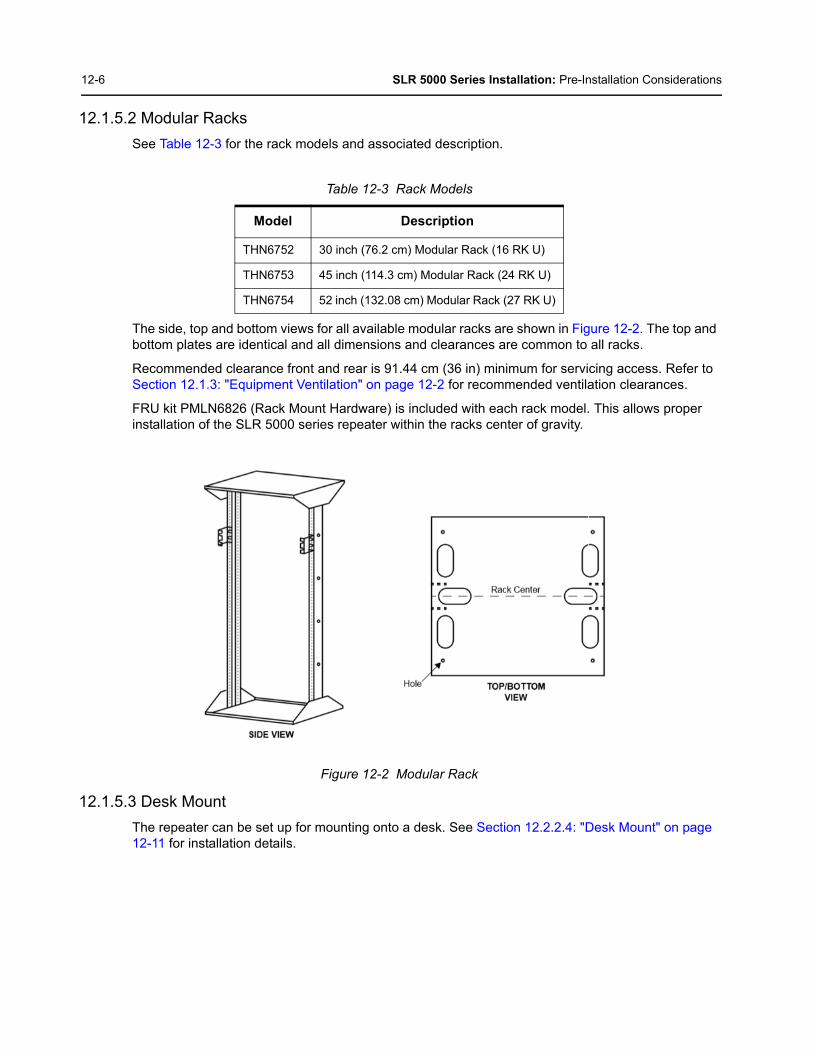
12-6 SLR 5000 Series Installation: Pre-Installation Considerations
12.1.5.2 Modular Racks
See Table 12-3 for the rack models and associated description.
The side, top and bottom views for all available modular racks are shown in Figure 12-2. The top and bottom plates are identical and all dimensions and clearances are common to all racks.
Recommended clearance front and rear is 91.44 cm (36 in) minimum for servicing access. Refer to Section 12.1.3: "Equipment Ventilation" on page 12-2 for recommended ventilation clearances.
FRU kit PMLN6826 (Rack Mount Hardware) is included with each rack model. This allows proper installation of the SLR 5000 series repeater within the racks center of gravity.
Figure 12-2 Modular Rack
12.1.5.3 Desk Mount
The repeater can be set up for mounting onto a desk. See Section 12.2.2.4: "Desk Mount" on page 12-11 for installation details.
Table 12-3 Rack Models
Model Description
THN6752 30 inch (76.2 cm) Modular Rack (16 RK U)
THN6753 45 inch (114.3 cm) Modular Rack (24 RK U)
THN6754 52 inch (132.08 cm) Modular Rack (27 RK U)

SLR 5000 Series Installation: Pre-Installation Considerations 12-7
12.1.6 Site Grounding and Lightning Protection
One of the most important considerations when designing a communications site is the ground and lightning protection system. While proper grounding techniques and lightning protection are closely related, the general category of site grounding may be divided into the following sections.
12.1.6.1 Electrical Ground
Ground wires carrying electrical current from circuitry or equipment at the site is included in the category of electrical ground. Examples include the AC or DC electrical power used to source equipment located at the site, and wires or cables connected to alarms or sensors located at the site.
12.1.6.2 RF Ground
This type of ground is related to the bypassing of unwanted radio frequency energy to earth ground. An example of RF grounding is the use of shielding to prevent or at least minimize the leakage of unwanted RF energy from communications equipment and cables.
12.1.6.3 Lightning Ground
Providing adequate lightning protection is critical to a safe reliable communications site. RF transmission cables, and AC and DC power lines must all be protected to prevent lightning energy from entering the site.
Comprehensive coverage of site grounding techniques and lightning protection is not within the scope of this instruction manual, but there are several excellent industry sources for rules and guidelines on grounding and lightning protection at communications sites.
12.1.6.4 Equipment Grounding
The repeater is equipped with a ground screw located on the rear of the repeater power supply module. This screw is used to connect the repeater to the site grounding. All antenna cables, and AC and DC power cabling, should be properly grounded and lightning protected by following the rules and guidelines provided in the above reference. Failure to provide proper lightning protection may result in permanent damage to the repeater.
12.1.7 Recommended Tools and Equipment
In addition to the typical compliment of hand tools, the following tools and equipment are recommended for proper installation of the repeater equipment.
• Tarpaulin or plastic drop cloth or cover surrounding equipment while drilling concrete anchor holes (for installations where cabinet or rack is being anchored to concrete).
• Vacuum cleaner for removing concrete dust caused by drilling.
Proper site grounding and lightning protection are vitally important considerations. Failure to provide proper lightning protection may result in permanent damage to the radio equipment.
Note Motorola recommends the following reference source: Motorola Quality Standards Fixed Network Equipment Installation Manual R56.

12-8 SLR 5000 Series Installation: Pre-Installation Considerations
12.1.8 Equipment Unpacking and Inspection
12.1.8.1 Unpacking Equipment
Refer Section 1.9: "Model Chart" on page 1-15.
Remove repeater from cardboard box. Remove foam corners and remove repeater from anti static bag. Keep all packing components for future shipping of repeater.
12.1.8.2 Initial Inspection
• After removing the repeater from the packaging, set on the surface for inspection. Top and bottom protective covers should be free of damage. Front housing should have no obvious scuffs or marks.
• Back Panel connectors should be free of damage. Connectors should not be bent with regard to the back panel. Threads on RF connectors should be free of debris and undamaged.
• Remove protective liner from lens on LED display.
• If any part of the equipment has been damaged in transit, immediately report the extent of the damage to the transportation company and to Motorola.
• When a repeater is delivered from Motorola, it arrives in suitable packing materials. If the unpacked equipment is damaged, return it to Motorola in its original packaging.
Equipment should be handled in its original packaging until it is delivered to its final destination. If the equipment is damaged while being moved without the original packaging, the warranty claim is not valid.

SLR 5000 Series Installation: Mechanical Installation 12-9
12.2 Mechanical Installation
12.2.1 Equipment Unpacking and Inspection
Remove repeater from cardboard box. Remove foam corners and remove repeater from anti static bag.
Thoroughly inspect the equipment as soon as possible after delivery. If any part of the equipment has been damaged in transit, immediately report the extent of the damage to the transportation company and to Motorola.
When a repeater is delivered from Motorola, it arrives in suitable packing materials. If the unpacked equipment is damaged, return it to Motorola in its original packaging.
12.2.2 Mounting Procedures
The repeaters can be mounted in the selected cabinet or rack, and may be installed by following the procedures below.
12.2.2.1 Transferring Equipment from Shipping Container to Rack or Cabinet
As mentioned under Equipment Unpacking and Inspection, a repeater can be shipped in a box. Upon delivery, the equipment must be removed from the container and transferred to a rack or cabinet.
Note Antistatic plastic bags and foam corners should be kept for future shipping/transporting ofrepeater.
Equipment should be handled in its original packaging until it is delivered to its final destination. If the equipment is damaged while being moved without the original packaging, the warranty claim is not valid.
Improper handling of the repeater may cause personal injury or damage to the repeater.

12-10 SLR 5000 Series Installation: Mechanical Installation
12.2.2.2 Installing Racks
In a typical installation, the rack is bolted to a concrete floor to provide stability.
The following procedure describes the steps necessary to bolt the rack to a concrete floor. Be sure to check with local authorities to verify that the following procedure conforms to local building codes and regulations before permanently installing the rack.
1. Carefully align the rack at the desired anchoring location.
2. Use the rack mounting foot as a template and mark the location of the six 19 mm (3/4 in) diameter mounting holes. All six anchoring positions must be used.
3. Move the rack aside, drill holes in the concrete floor, and install the mounting anchors (RAM RD-56 anchors recommended) per instructions provided with the anchors. Make sure that none of the anchors comes in contact with the reinforcing wire mesh buried in the concrete; the rack must be electrically isolated from any other equipment or materials at the site.
4. Align the rack with the installed anchors and lightly secure the rack to the floor using the proper mounting hardware. Do not tighten the mounting hardware at this time.
5. Check the vertical plumb of the rack. Also check that the top is level. Use shims (flat washers or flat aluminum plates) as necessary under the rack mounting foot to achieve vertical plumb and horizontal level.
6. Tightly secure the rack to the floor anchors making sure that it remains vertically plumb and horizontally level.
7. Assemble the two mounting brackets to each side of the repeater either in the front or middle of the repeater depending on whether rack is made for front mount or mid-mount using three supplied screws for each bracket.
Note Cabinets and racks must have mounting rails and hole spacing compatible with EIAUniversal 48.3 cm (19 in) specifications. Cabinets must provide adequate ventilation (asdetailed under Equipment Ventilation) and must meet the following criteria:
• 41.3 cm (16.25 in) deep
• 48.3 cm (19 in) wide
• 13.4 cm (5.25 in) high
• Two mounting rails 5 cm (2 in) from front of cabinet with front mounting holes 5.7 cm (2.25 in) apart (center to center).
Contact Motorola Customer Support for specific questions regarding mounting equipment incustomer-supplied cabinets.

SLR 5000 Series Installation: Mechanical Installation 12-11
8. Hold repeater in the desired rack location. Line up mounting bracket holes with mounting locations on rack rail and assemble both brackets to the mounting rail on the rack using 10-32 screws.
12.2.2.3 Installing Cabinets
Each cabinet bottom is pre-drilled with four (4) mounting holes to allow attachment to the site floor. If installing on a concrete floor, use the cabinet as a template, mark the hole locations, and follow the procedures above for anchoring equipment racks. If installing on a wooden floor, use lag bolts and washers (customer supplied) to secure the cabinet to the floor.
12.2.2.4 Desk Mount
To use the repeater as a desk mount, install mounting brackets (PN: 07009401001) at a 90 degree angle as shown in Figure 12-3 using two M4 screws (PN: 0310907A99) for each bracket using a T20 Torx driver at 15 in-lb (1.7 N-m). Then push a rubber foot (PN: 75009498001) into each bracket as shown in Figure 12-3. Next push two rubber feet (PN: 75009502001) into the base frame also shown in Figure 12-3.
Figure 12-3 Desk Mount Installation
Cement dust from concrete flooring is harmful to electronic equipment and wiring. Make sure that the rack and any collocated equipment are protected prior to drilling holes in the concrete floor. Use a tarpaulin, cloth, or plastic sheeting to cover exposed equipment. (The rack should be already covered with an antistatic bag; do not remove the bag at this time.) Use a vacuum while drilling the holes to minimize the spread of concrete dust. Carefully clean up any accumulated dust and debris from the anchor installation before uncovering the equipment.
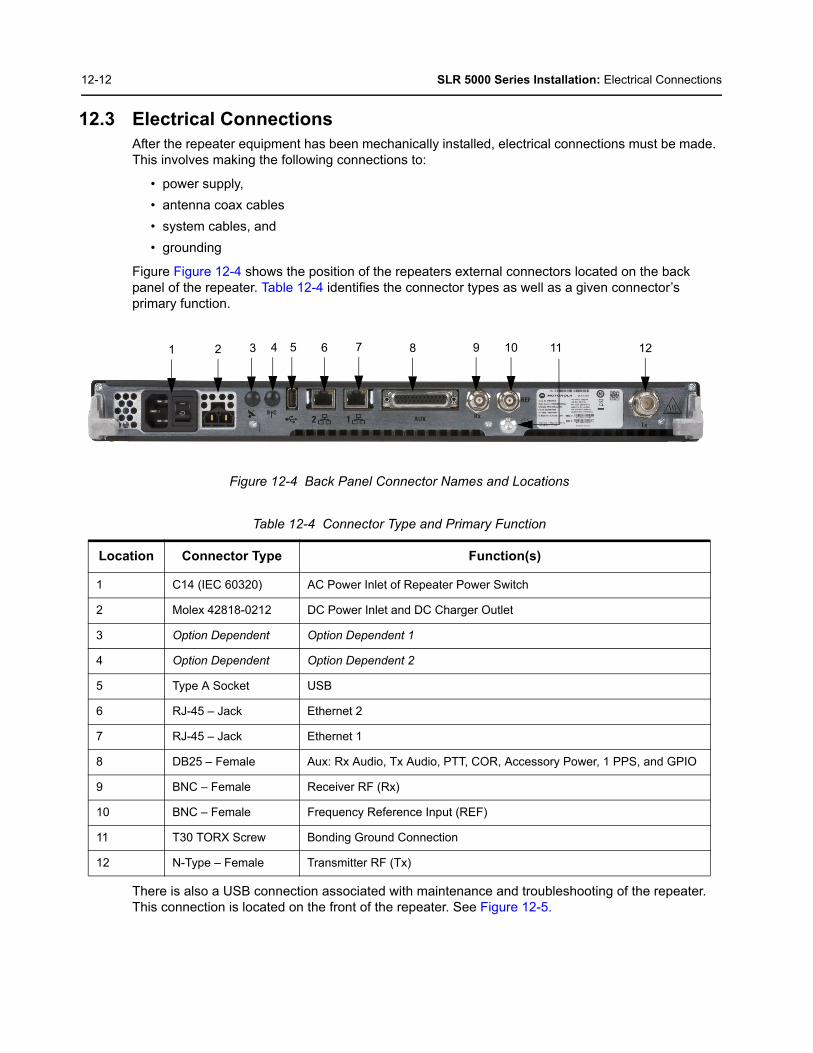
12-12 SLR 5000 Series Installation: Electrical Connections
12.3 Electrical ConnectionsAfter the repeater equipment has been mechanically installed, electrical connections must be made. This involves making the following connections to:
• power supply,
• antenna coax cables
• system cables, and
• grounding
Figure Figure 12-4 shows the position of the repeaters external connectors located on the back panel of the repeater. Table 12-4 identifies the connector types as well as a given connector’s primary function.
Figure 12-4 Back Panel Connector Names and Locations
There is also a USB connection associated with maintenance and troubleshooting of the repeater. This connection is located on the front of the repeater. See Figure 12-5.
Table 12-4 Connector Type and Primary Function
Location Connector Type Function(s)
1 C14 (IEC 60320) AC Power Inlet of Repeater Power Switch
2 Molex 42818-0212 DC Power Inlet and DC Charger Outlet
3 Option Dependent Option Dependent 1
4 Option Dependent Option Dependent 2
5 Type A Socket USB
6 RJ-45 – Jack Ethernet 2
7 RJ-45 – Jack Ethernet 1
8 DB25 – Female Aux: Rx Audio, Tx Audio, PTT, COR, Accessory Power, 1 PPS, and GPIO
9 BNC – Female Receiver RF (Rx)
10 BNC – Female Frequency Reference Input (REF)
11 T30 TORX Screw Bonding Ground Connection
12 N-Type – Female Transmitter RF (Tx)
2 3 6 8 9 10 11 124 5 71

SLR 5000 Series Installation: Electrical Connections 12-13
Figure 12-5 Location of USB Connector
12.3.1 Power Supply Connections
12.3.1.1 AC Input Power Connection
Each repeater is shipped with an 2.5 m (8 ft) 3-conductor line cord. Figure 12-4 shows the AC power inlet connector. Insert the plug into an appropriate grounded outlet. The North American line cord is equipped with a NEMA 5–15 plug, intended for 110/ 120 VAC operation. The European line cord is equipped with a “Schuko” style CEE VII (7) plug, intended for 220/ 240 VAC operation.
12.3.1.2 DC Input Power Connection/ DC Charger Connection
For DC operation, the DC source power is connected to the repeater through the DC power inlet connector shown in Figure 12-4. The operation is also described in the “Battery Connection” section of this chapter. The DC source must be located in the same building as the repeater, and it must meet the requirements of an SELV circuit.
12.3.1.3 Ground Connection
The repeater is equipped with a ground screw located on the back panel. Figure 12-4 shows the location of the grounding screw. Connect the ground screw to the site ground point. The size of the wire used for this connection must be 8 AWG minimum.
Do not apply AC power to the repeater at this time. Make sure that the circuit breaker associated with the AC outlet is turned OFF.
The AC socket-outlet must be installed near the equipment and must be easily accessible.
Ensure that the appropriate voltage is connected with a nominal 13.6 VDC (11 – 14.4 VDC).
Refer to Motorola Quality Standards Fixed Network Equipment Installation Manual R56 for complete information regarding lightning protection.
The repeater should only be connected to a battery supply that is in accordance with the applicable electrical codes for the end use country; for example, the National Electrical Code ANSI/ NFPA No. 70 in the U.S.
USB Service Port

12-14 SLR 5000 Series Installation: Post Installation Checklist
12.3.1.4 Battery Connection
Battery backup interface offers the capability of connecting to battery backup power in the event of an AC power line failure. The battery backup system is connected to the repeater through the DC inlet connector on the rear panel of the repeater. See Figure 12-4 for the location of the DC inlet connector.
12.3.1.5 RF Antenna Connections
The transmit and receive antenna RF connections are made using two separate connectors. Coax cables from the receive and transmit antennas must be connected to their respective connectors. The position of these connectors is shown in Figure 12-4, and their respective connector types are noted in Table 12-4.
12.3.1.6 System Cable Connections
System connections are made through the Aux and/or Ethernet connectors located on the back panel of the repeater. The positions of the Aux and Ethernet connectors are shown in Figure 12-4.
See Section 7.2.8: "Auxiliary (Aux)" on page 7-6 for a description of the signaling that is supported by the Aux connector.
12.4 Post Installation ChecklistAfter the MOTOTRBO Repeater has been mechanically installed and all electrical connections have been made, power may now be applied and the repeater checked for proper operation.
12.4.1 Applying Power
Turn ON the circuit breaker controlling the AC outlet that is supplying power to the repeater Power Supply Module.
The repeater should only be connected to a battery supply that is in accordance with the applicable electrical codes for the end use country; for example, the National Electrical Code ANSI/ NFPA No. 70 in the U.S.
SLR 5000 Series Installation: Installing Repeater Hardware Options 12-15
12.4.2 Verifying Proper Operation
Operation of the repeater can be verified by:
• Observing the state of the 7 LEDs located on the front panel, and
• Exercising radio operation.
12.4.3 Front Panel LEDs
After turning ON the repeater power (or after a repeater reset), the 7 LEDs on the repeater front panel:
• Light for approximately one second to indicate that they are functional, then
• Go off for one second, then
• Indicate the operational status of the repeater.
12.4.4 Copying the Repeater Codeplug Data to a Computer
Backup the repeater's codeplug data by using the Customer Programming Software (CPS) on a computer.
12.5 Installing Repeater Hardware Options
12.5.1 General Bonding and Grounding Requirements
Cabinets and racks used to mount the repeater and optional equipment include a rack grounding bar with the capacity to terminate numerous ground wires. Equipment added to the cabinet or rack should be attached to the grounding bar using solid or stranded 6 AWG copper wires. See the Motorola R56 manual Standards and Guidelines for Communication Sites for more information on proper bonding and grounding at a site.
12.5.2 General Cabling Requirements
Diagrams for cabling are typically included in the system–specific configuration documentation provided by Motorola. Also see the Motorola R56 manual Standards and Guidelines for Communication Sites for cabling standards.
Some repeater components can become extremely hot during operation. Turn OFF all power to the repeater and wait until sufficiently cool before touching the repeater.
Symbol indicates areas of the product that pose potential burn hazards.

12-16 SLR 5000 Series Installation: Installing Repeater Hardware Options
Notes

Appendix A Accessories
A.1 IntroductionMotorola provides the following approved accessories to improve the productivity of the SLR 5000 Series Repeater.
For a list of Motorola-approved accessories, visit the following web site: http://www.motorolasolutions.com
A.1.1 Cables
A.1.2 Documentation
A.1.3 Mounting
Part No. Description
3087791G04 Power Cable, Euro
3087791G07 Power Cable, UK
3087791G10 Power Cable, Aus & NZ
PMKN4167_ Battery Charger Cable
Part No. Description
6880309T12 MOTOTRBO System Planner
GMLN4575_ MOTOTRBO Publication CD
GMVN5141_ MOTOTRBO Software DVD
GMVN5520_ MOTOTRBO RDAC Software CD
Part No. Description
PMLN6826_ Mounting Hardware Kit
07009401001 Mounting Bracket (Short)
0310907A99 Mounting Bracket Screw, M4 x 8 mm, black
75009498001 Rubber Feet (Front - Mounting Bracket)
75009502001 Rubber Feet (Rear)
BR000031A01 Mounting Bracket (Long, Rack Mount Shipping only)
PMLE5031_ Wall Mount Bracket Kit

A-2 Accessories: Introduction
A.1.4 Service Parts
A.1.5 Service Tools
Part No. Description
WAED4531_ SL 5000 Series VHF Modem Service Kit
WAEE4501_ SL 5000 Series UHF1 Modem Service Kit
PMTD4012_S SLR 5000 Series VHF PA Service Kit
PMTE4023_S SLR 5000 Series UHF1 PA Service Kit
PMPN4026_S SLR 5000 Series Power Supply Service Kit
PMLN6490_S SLR 5000 Series Front Panel Board Service Kit
PMHN4299_ Chassis Service Kit(contact Motorola Service Center for replacement)
PMLN7244_ SLR 5000 Series Fan Assembly Service Kit
Part No. Description
PMKN4166_ Test Cable (for test box and external speaker)
30009477001 USB A to USB B Cable (for programming)
RLN4460_ Test Box
HSN1006_ Speaker, Amplified
GMMN4063_ Microphone, RJ45

Appendix B EMEA Regional Warranty, Service and Technical Support
B.1 Warranty and Service SupportMotorola offers long term support for its products. This support includes full exchange and/or repair of the product during the warranty period, and service/ repair or spare parts support out of warranty. Any "return for exchange" or "return for repair" by an authorized Motorola Dealer must be accompanied by a Warranty Claim Form. Warranty Claim Forms are obtained by contacting an Authorized Motorola Dealer.
B.1.1 Warranty Period and Return Instructions
The terms and conditions of warranty are defined fully in the Motorola Dealer or Distributor or Reseller contract. These conditions may change from time to time and the following notes are for guidance purposes only.
In instances where the product is covered under a "return for replacement" or "return for repair" warranty, a check of the product should be performed prior to shipping the unit back to Motorola. This is to ensure that the product has been correctly programmed or has not been subjected to damage outside the terms of the warranty.
Prior to shipping any radio back to the appropriate Motorola warranty depot, please contact Customer Resources (Please see page B-2). All returns must be accompanied by a Warranty Claim Form, available from your Customer Services representative. Products should be shipped back in the original packaging, or correctly packaged to ensure no damage occurs in transit.
B.1.2 After Warranty Period
After the Warranty period, Motorola continues to support its products in two ways.
1. Motorola's Managed Technical Services (MTS) offers a repair service to both end users and dealers at competitive prices.
2. MTS supplies individual parts and modules that can be purchased by dealers who are technically capable of performing fault analysis and repair.
B.2 European Radio Support Centre (ERSC)
European Repair and Service Centre: Telephone: +49 30 6686 1555Fax ERSC: +49 30 6686 1579Email ERSC: [email protected]
Please use these numbers for repair enquiries only.

B-2 EMEA Regional Warranty, Service and Technical Support: Piece Parts
B.3 Piece PartsSome replacement parts, spare parts, and/or product information can be ordered directly. While parts may be assigned with a Motorola part number, this does not guarantee that they are available from Motorola Radio Products and Solutions Organization (RPSO). Some parts may have become obsolete and no longer available in the market due to cancellations by the supplier. If no Motorola part number is assigned, the part is normally not available from Motorola, or is not a user-serviceable part. Part numbers appended with an asterisk are serviceable by Motorola Depot only.
Orders for replacement parts, kits and assemblies should be placed directly on Motorola's local distribution/dealer organisation or via Motorola Online at: https://emeaonline.motorolasolutions.com
* The Radio Products and Solutions Organization (RPSO) was formerly known as the Radio Products Services Division (RPSD) and/or the Accessories and Aftermarket Division (AAD).
B.4 Technical SupportMotorola Product Services is available to assist the dealers/distributors in resolving any malfunctions which may be encountered.
Contact Details:
Email: [email protected]
The Technical Support is available through the following service numbers:
Austria: 01206091087 Poland: 00 800 141 0252
Denmark: 043682114 Portugal: 0217616160
France: 0157323434 Russia: 810 800 228 41044/810 800 120 1011
Germany: 06950070204 Saudi Arabia: 800 844 5345
Israel: 180 931 5818 South Africa: 0800981900
Italy: 0291483230 Spain: 0912754787
Lithuania: 880 030 828 United Kingdom: 02030 277499
Netherlands: 0202061404 All other countries: +44 2030 277499
Norway: 24159815
B.5 Further Assistance From MotorolaYou can also contact the Customer Help Desk through the following web address.http://www.motorolasolutions.com

Appendix C SLR 5000 Series Third Party Controllers
C.1 OverviewThe SLR 5000 Series Repeater is capable of interfacing to a number of third party controllers via the four-wire and GPIO/ GPI interface afforded by the back panel AUX connector. This section covers the connections and signal levels between the third party controllers and the repeater, as well as the audio path configuration needed via CPS. Note that this section is not a substitute for a more comprehensive instruction detailed in the vendor’s manuals of their respective third party controllers.
The third party controllers supported by SLR 5000 Series Repeater are as follows:
• Community Repeater Panel (Zetron Model 38-Max)
• Phone Patch (Zetron Model 30)
• Tone Remote Adapter (Motorola Model L3276)
• LTR (Trident Model Raider and Marauder)
• Passport (Trident Model NTS) (see Note)
Do not hot swap any of the third party controllers as this could (at a minimum) cause a malfunction with the repeater.
Note The SLR 5000 Series Repeater only support the third party controllers noted above when itis configured in analog mode. The screen capture below shows the CPS location toconfigure the SLR 5000 Series Repeater for analog mode.
Note If the third party controllers are supplied power by the SLR 5000 Series Repeater, then theSLR 5000 Series Repeater needs to be in a powered off state when establishing (orremoving) the connection to the SLR 5000 Series back panel connector.
C a u t i o n

C-2 SLR 5000 Series Third Party Controllers: Community Repeater Panel
Figure C-1 CPS Settings to Configure SLR 5000 Series Repeater for Analog Mode
C.2 Community Repeater Panel
C.2.1 Description
The SLR 5000 Series Repeater is capable of Multi Coded Squelch through the Zetron Model 38 Repeater Panel. The Model 38 Repeater Panel interconnects to the SLR 5000 Series Repeater and provides 38 PL tones and 22 DPL tones standard.
See Zetron Model 38 Repeater Panel Instruction Manual (supplied with the panel) for panel specifications, operation, installation, alignment, programming, and repair information.
Figure C-2 Model Zetron 38 Repeater Panel
C.2.2 Compatibility
Zetron Model 38 Repeater Panel is compatible for all versions of SLR 5000 Series software and hardware.

SLR 5000 Series Third Party Controllers: Community Repeater Panel C-3
C.2.3 Hardware Connections
The connections between the SLR 5000 Series Repeater and the community repeater panel are facilitated with a multi-conductor cable connected between the SLR 5000 back panel AUX 25-Pin connector and that of the community repeater panel. The connection provides the following signals:
• Transmit Audio
• Receiver Audio
• Push-to-talk (PTT)
• Carrier Operated Relay (COR)
• 13.6 VDC nominal (See note)
• Ground
Signal connections are noted in Figure C-1. The SLR 5000 Series connector and physical Pin locations are noted in the backplane interface board section of this manual. See Zetron Model 38 Repeater Panel manual for its connector and physical Pin locations. The part number for a pre-fabricated cable is noted in the SLR 5000 Series ordering guide.
Figure C-3 Signal Connections between SLR 5000 Series Repeater and Community Repeater Panel
Note If this connection is used, the external equipment must draw less than 1A.
Blue
Black (Paired with Blue)
Shield from Blk/Blue Pair
White
Black (Paired with White)
Shield from Blk/White Pair
Green
Black (Paired with Green)
Shield from Blk/Green Pair
Red
Black (Paired with Red)
Shield from Blk/Red Pair
Male DB25 Terminal BlockModel 38SLR 5000 Series
GP1 (PTT)
GPIO2 (CSQ)
Gnd
Emph Tx Audio
Tx Data
Gnd
Gnd
Gnd
Gnd
GndGnd
Gnd
Rx Audio
13.6 VDC
PTT N.O.
COR Input
PTT Common
TX Audio
CTCSS Out
Discriminator
12VDC+
12VGnd
2
4
7
10
6
11
13
12
15
14
4
1
3
18
22
13
17
7
9
16
20
19

C-4 SLR 5000 Series Third Party Controllers: Community Repeater Panel
C.2.4 CPS Configuration
The SLR 5000 Series Repeater will need to be configured via the CPS application as shown in Figure C-4 and Figure C-5. More specifically, the affected parameters are as follows:
• Audio Type
- Flat Unsquelched
• Disable Repeat Path
- Checked
• GPIO Pin number 2, 11
- Ext PTT
- Active Low
• GPIO Pin number 4
- Carrier Squelch (CSQ) Detect
- Active High
• Squelch Type (Rx)
- CSQ
• Squelch Type (Tx)
- CSQ
Figure C-4 CPS Configuration for Community Repeater Panel (1 of 2)
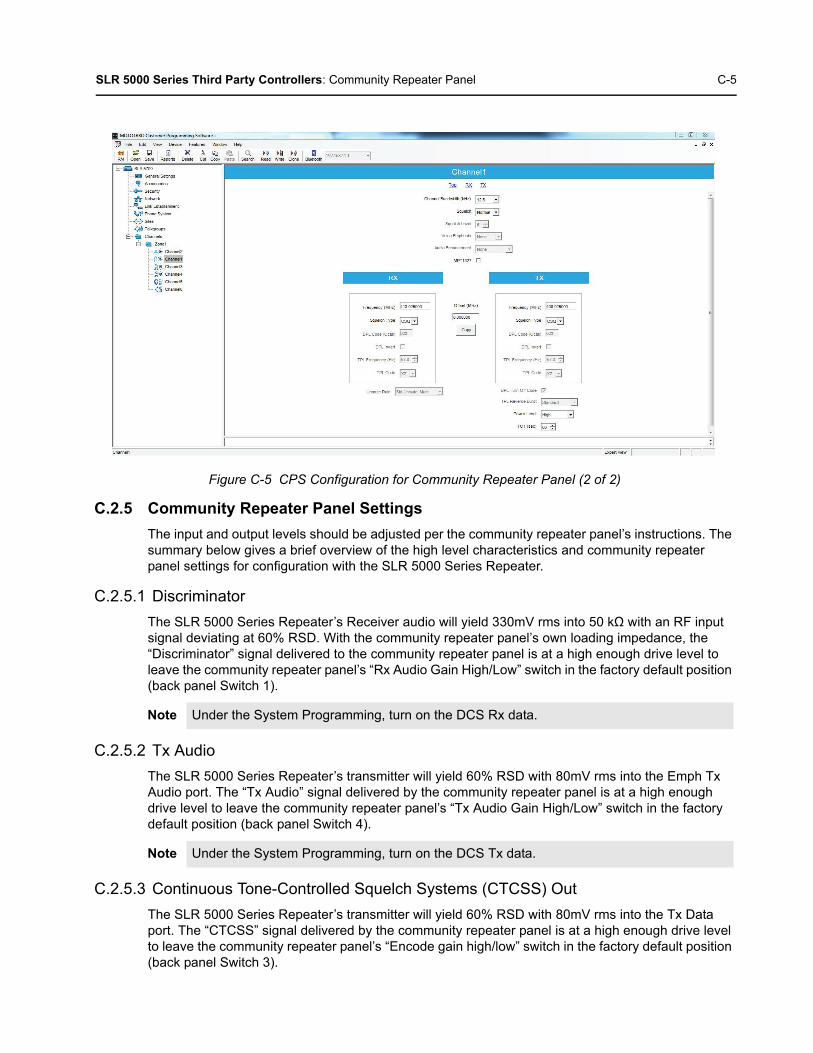
SLR 5000 Series Third Party Controllers: Community Repeater Panel C-5
Figure C-5 CPS Configuration for Community Repeater Panel (2 of 2)
C.2.5 Community Repeater Panel Settings
The input and output levels should be adjusted per the community repeater panel’s instructions. The summary below gives a brief overview of the high level characteristics and community repeater panel settings for configuration with the SLR 5000 Series Repeater.
C.2.5.1 Discriminator
The SLR 5000 Series Repeater’s Receiver audio will yield 330mV rms into 50 kΩ with an RF input signal deviating at 60% RSD. With the community repeater panel’s own loading impedance, the “Discriminator” signal delivered to the community repeater panel is at a high enough drive level to leave the community repeater panel’s “Rx Audio Gain High/Low” switch in the factory default position (back panel Switch 1).
C.2.5.2 Tx Audio
The SLR 5000 Series Repeater’s transmitter will yield 60% RSD with 80mV rms into the Emph Tx Audio port. The “Tx Audio” signal delivered by the community repeater panel is at a high enough drive level to leave the community repeater panel’s “Tx Audio Gain High/Low” switch in the factory default position (back panel Switch 4).
C.2.5.3 Continuous Tone-Controlled Squelch Systems (CTCSS) Out
The SLR 5000 Series Repeater’s transmitter will yield 60% RSD with 80mV rms into the Tx Data port. The “CTCSS” signal delivered by the community repeater panel is at a high enough drive level to leave the community repeater panel’s “Encode gain high/low” switch in the factory default position (back panel Switch 3).
Note Under the System Programming, turn on the DCS Rx data.
Note Under the System Programming, turn on the DCS Tx data.
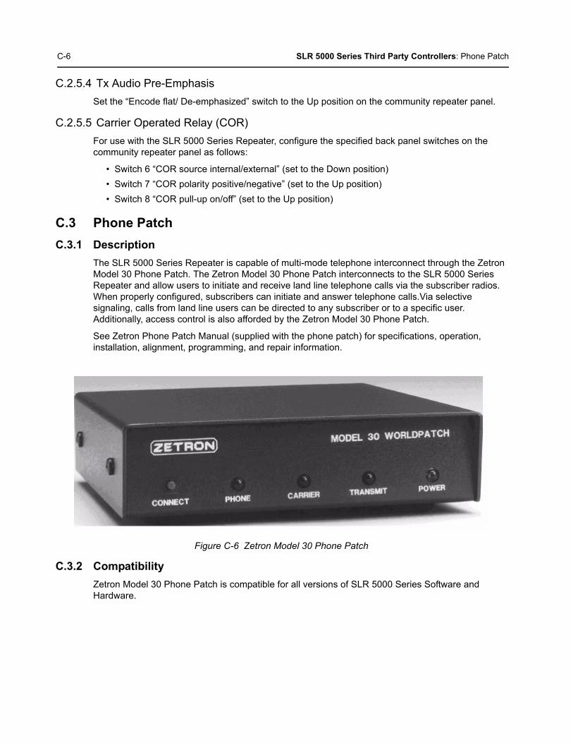
C-6 SLR 5000 Series Third Party Controllers: Phone Patch
C.2.5.4 Tx Audio Pre-Emphasis
Set the “Encode flat/ De-emphasized” switch to the Up position on the community repeater panel.
C.2.5.5 Carrier Operated Relay (COR)
For use with the SLR 5000 Series Repeater, configure the specified back panel switches on the community repeater panel as follows:
• Switch 6 “COR source internal/external” (set to the Down position)
• Switch 7 “COR polarity positive/negative” (set to the Up position)
• Switch 8 “COR pull-up on/off” (set to the Up position)
C.3 Phone Patch
C.3.1 Description
The SLR 5000 Series Repeater is capable of multi-mode telephone interconnect through the Zetron Model 30 Phone Patch. The Zetron Model 30 Phone Patch interconnects to the SLR 5000 Series Repeater and allow users to initiate and receive land line telephone calls via the subscriber radios. When properly configured, subscribers can initiate and answer telephone calls.Via selective signaling, calls from land line users can be directed to any subscriber or to a specific user. Additionally, access control is also afforded by the Zetron Model 30 Phone Patch.
See Zetron Phone Patch Manual (supplied with the phone patch) for specifications, operation, installation, alignment, programming, and repair information.
Figure C-6 Zetron Model 30 Phone Patch
C.3.2 Compatibility
Zetron Model 30 Phone Patch is compatible for all versions of SLR 5000 Series Software and Hardware.

SLR 5000 Series Third Party Controllers: Phone Patch C-7
C.3.3 Hardware Connections
The connections between the SLR 5000 Series Repeater and the phone patch are facilitated with a multi-conductor cable connected between the J7 SLR 5000 Series back panel Aux 25-Pin connector and that of the phone patch. The connection provides for the following signals:
• Transmit Audio
• Receiver Audio
• PTT
• COR
• 13.6 VDC Nominal (see Note)
• Ground
Signal connections are noted in Figure C-2. The SLR 5000 Series Repeater connector and physical Pin locations are noted in the backplane interface board section of this manual. See Zetron Model 30 manual for its connector and physical Pin locations. The part number for a pre-fabricated cable is noted in the SLR 5000 Series ordering guide.
Figure C-7 Signal Connections between SLR 5000 Series Repeater and Zetron Model 30 Phone Patch (Analog Phone Patch Cable & Digital Phone Patch Cable)
Note If this connection is used, the external equipment must draw less than 1A.
White
Black (Paired with White)
Shield from Blk/White Pair
Green
Black (Paired with Green)
Shield from Blk/Green Pair
Red
Black (Paired with Red)
Shield from Blk/Red Pair
Model 30
Molex 1x 10 Connector
Tx Audio
PTT
Gnd
Discriminator
COR Input
Gnd
12VDC+
Gnd
SLR 5000 Series
Male DB25
Tx Audio
GPI 1 (PTT)
Gnd
Rx Audio
Gnd
13.6 VDC
Gnd
1
2
16
7
4
17
20
19
18
5
7
4
3
8
6
1
2

C-8 SLR 5000 Series Third Party Controllers: Phone Patch
C.3.4 CPS Configuration
The SLR 5000 Series Repeater will need to be configured via the CPS application as shown in Figure C-4 and Figure C-5. More specifically, the affected parameters are as follows:
• Audio Type
- Filtered Squelch
• Analog Accessory Emphasis
- De & Pre
• Disable Repeat Path
- Un-Checked
• Tx Audio Priority
- 0
• GPIO Pin number 2, 11
- Ext PTT
- Active Low
• GPIO Pin number 4
- PL/Talkgroup Detect
- Active Low
• Squelch Type (Rx)
- TPL
• Squelch Type (Tx)
- TPL
Figure C-8 CPS Configuration for Phone Patch (1 of 2)

SLR 5000 Series Third Party Controllers: Phone Patch C-9
Figure C-9 CPS Configuration for Phone Patch (2 of 2)
C.3.5 Phone Patch Level Settings
The input and output levels should be adjusted per the phone patch’s instructions. The summary below gives a brief overview of the high level characteristics and phone patch settings for configuration with the SLR 5000 Series.
C.3.5.1 Disc
The SLR 5000 Series Repeater’s Receiver audio will yield 330mV rms into 50 kΩ with an RF input signal deviating at 60% RSD. With the phone patch’s own loading impedance, the “Disc” signal delivered to the phone patch is at a high enough drive level to leave jumper JP1 in the factory default position (position A).
C.3.5.2 Tx Audio
The SLR 5000 Series Repeater’s transmitter will yield 60% RSD with 80mV rms into the Tx Audio port. The “Tx Aud” signal delivered by the phone patch is at a high enough drive level to leave jumper JP3 in the factory default position (position B).
C.3.5.3 CTCSS/ DCS DECODE INPUT/ COR
Set jumper JP6 to position A, to match the SLR 5000 Series’ active low indication of a PL/DPL detect.
Set jumper JP7 to position B, to external squelch indication.
Set jumper JP8 to position C, to match the SLR 5000 Series’ active low indication of a COR detect.

C-10 SLR 5000 Series Third Party Controllers: Tone Remote Adapter
C.4 Tone Remote Adapter
C.4.1 Description
When a dispatch console or deskset sends out signals to a remote repeater, it does so over a Wireline. Two types of signals are sent:
• Audio signal
• Command signals (function tones) that are used to perform the remote control functions.
The SLR 5000 Series Repeater is capable of decoding function tones, sent over a Wireline from a remote analog deskset or console, via the Motorola Tone Remote Adapter (Model L3276). When properly configured, the Tone Remote Adapter will perform the following functions in conjunction with the SLR 5000 Series Repeater:
• Transmit and Receive Audio
• PTT
• Monitor
• Channel Select (up to 15 frequencies)
• Wildcard (e.g. Repeater Knockdown)
See Motorola Tone Remote Adapter Manual (supplied with the Tone Remote Adapter) for specifications, operation, installation, alignment, programming, alternate configurations, and repair information.
Figure C-10 Model L3276 Tone Remote Adapter
C.4.2 Compatibility
Model L3276 Tone Remote Adapter is compatible for all versions of SLR 5000 Series Software and Hardware.
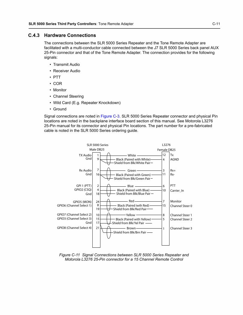
SLR 5000 Series Third Party Controllers: Tone Remote Adapter C-11
C.4.3 Hardware Connections
The connections between the SLR 5000 Series Repeater and the Tone Remote Adapter are facilitated with a multi-conductor cable connected between the J7 SLR 5000 Series back panel AUX 25-Pin connector and that of the Tone Remote Adapter. The connection provides for the following signals:
• Transmit Audio
• Receiver Audio
• PTT
• COR
• Monitor
• Channel Steering
• Wild Card (E.g. Repeater Knockdown)
• Ground
Signal connections are noted in Figure C-3. SLR 5000 Series Repeater connector and physical Pin locations are noted in the backplane interface board section of this manual. See Motorola L3276 25-Pin manual for its connector and physical Pin locations. The part number for a pre-fabricated cable is noted in the SLR 5000 Series ordering guide.
Figure C-11 Signal Connections between SLR 5000 Series Repeater and Motorola L3276 25-Pin connector for a 15 Channel Remote Control
L3276
Female DB25
SLR 5000 Series
Male DB25
TX Audio
Rx Audio
GPI 1 (PTT)GPIO2 (CSQ)
GPIO5 (MON)GPIO6 (Channel Select 1)
GPIO7 (Channel Select 2)GPIO3 (Channel Select 3)
GPIO8 (Channel Select 4)
WhiteBlack (Paired with White)
Shield from Blk/White Pair
GreenBlack (Paired with Green)
Shield from Blk/Green Pair
BlueBlack (Paired with Blue)
Shield from Blk/Blue Pair
RedBlack (Paired iwth Red)
Shield from Blk/Red Pair
YellowBlack (Paired with Yellow)
Shield from Blk/Yel Pair
BrownShield from Blk/Brn Pair
Gnd
Gnd
Gnd
Gnd
19
7
16
24
18
248
19
101517
21
12
4
311
610
715
85
1
TxAGND
Rx+Rx-
PTT
Carrier_In
Monitor
Channel Steer 0
Channel Steer 1Channel Steer 2
Channel Steer 3

C-12 SLR 5000 Series Third Party Controllers: Tone Remote Adapter
C.4.4 CPS Configuration (For a 15 Channel Remote Control)
The SLR 5000 Series Repeater will need to be configured via the CPS application as shown in Figure C-12. More specifically, the affected parameters are as follows:
• Audio Type
- Filtered Squelch
• Analog Accessory Emphasis
- De & Pre
• Disable Repeat Path
- Un-Checked or Checked
• Tx Audio Priority
- Set to 0 for console priority
• GPIO Pin number 2, 11
- Ext PTT
- Active Low
• GPIO Pin number 4
- CSQ Detect or PL/ Talk group Detect
- Active Low
• GPIO Pin number 24
- Monitor
- Active Low
• GPIO Pin number 8, 25
- Channel Select 1
- Active Low
• GPIO Pin number 10, 12
- Channel Select 2
- Active Low
• GPIO Pin number 15
- Channel Select 3
- Active Low
• GPIO Pin number 21
- Channel Select 4
- Active Low

SLR 5000 Series Third Party Controllers: Tone Remote Adapter C-13
Figure C-12 CPS Configuration for L3276 Tone Remote Adapter (For a 15 Channel Remote Control)
Note The above configuration is considered typical. The L3276 Remote Tone Adapter providesalternate configurations that are supported by SLR 5000 Series Repeater as well. SeeL3276 Remote Tone Adapter Manual for additional details.
C-14 SLR 5000 Series Third Party Controllers: Tone Remote Adapter
C.4.5 Tone Remote Adapter settings
The input and output levels should be adjusted per the Tone Remote Adapter’s instructions. The summary below gives a brief overview of the high level characteristics and typical Tone Remote Adapter settings for configuration with the SLR 5000 Series Repeater.
C.4.5.1 Radio Rx
The SLR 5000 Series Repeater’s Receiver audio will yield 330mV rms into 50 kΩ with an RF input signal deviating at 60% RSD. With the Remote Tone Adapter’s own loading impedance, the “Radio Rx” signal delivered to the phone patch is at a high enough drive level to leave jumper S10 in the factory default position (position is “out”).
C.4.5.2 Radio Tx
The SLR 5000 Series Repeater’s transmitter will yield 60% RSD with 80mV rms into the Tx Audio port. The “Radio Tx” signal delivered by the Remote Tone Adapter is at a high enough drive level to leave jumper S9 in the factory default position (position A).
C.4.5.3 Channel Steering
Leave jumper S7 in position B (factory default) to match the SLR 5000 Series Repeater’s active low setting for the Channel Steering 1, Channel Steering 2, Channel Steering 3, and Channel Steering 4 GPIO signaling.
C.4.5.4 Monitoring
Leave jumper S8 in the “IN” position (factory default) to match the SLR 5000 Series’ active low setting for the Monitor GPIO signaling.
C.4.5.5 PTT
Leave jumper S5 in the “IN” position (factory default) to match the SLR 5000 Series’ active low setting for the PTT GPIO signaling.
C.4.5.6 Wildcard 1 (optional)
Leave jumper S6 in position A (factory default) to match the SLR 5000 Series’ active low setting for the Repeater Disabled GPIO signaling.
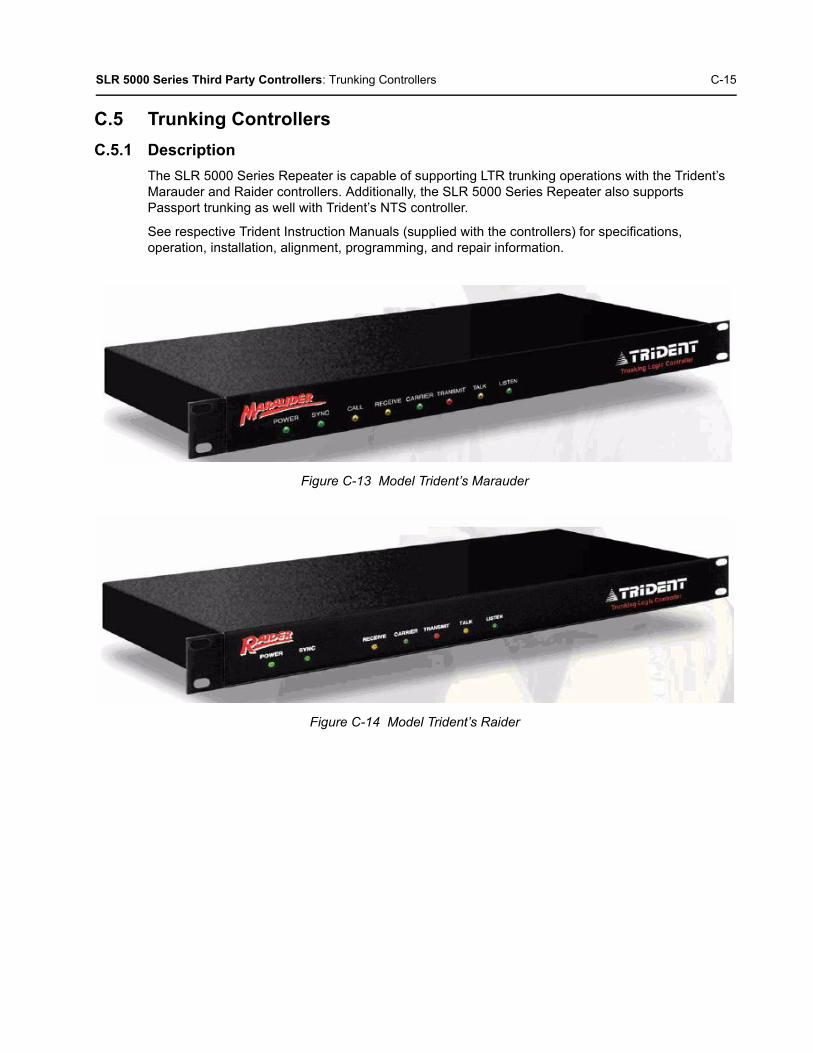
SLR 5000 Series Third Party Controllers: Trunking Controllers C-15
C.5 Trunking Controllers
C.5.1 Description
The SLR 5000 Series Repeater is capable of supporting LTR trunking operations with the Trident’s Marauder and Raider controllers. Additionally, the SLR 5000 Series Repeater also supports Passport trunking as well with Trident’s NTS controller.
See respective Trident Instruction Manuals (supplied with the controllers) for specifications, operation, installation, alignment, programming, and repair information.
Figure C-13 Model Trident’s Marauder
Figure C-14 Model Trident’s Raider

C-16 SLR 5000 Series Third Party Controllers: Trunking Controllers
Figure C-15 Model Trident’s NTS
C.5.2 Compatibility
Trident Model Raider, Marauder and NTS are compatible for all versions of SLR 5000 Series Software and Hardware.
C.5.3 Hardware Connections
The connections between the SLR 5000 Series Repeater and the trunking controllers are facilitated with a multi-conductor cable connected between the J7 SLR 5000 Series back panel AUX 25-Pin connector and that of the connector on the trunking controller. The connection provides for the following signals:
• Transmit Audio
• Transmit Data
• Receiver Audio
• PTT
• 13.6 VDC (see Note)
• Ground
Signal connections are noted in Figure C-4. The SLR 5000 Series Repeater connector and physical Pin locations are noted in the backplane interface board section of this manual. See the Trident manuals for their respective connector and physical Pin locations. The part number for a pre-fabricated cable is provided in the respective Trident manuals.
Note If this connection is used, the external equipment must draw less than 1A. This connectionis not supported for the NTS controller.

SLR 5000 Series Third Party Controllers: Trunking Controllers C-17
Figure C-16 Signal connections between SLR 5000 Series Repeater, Trident Model Raider, Marauder and NTS
Male DB25 Female DB25
Raider and MarauderSLR 5000 Series
White
Black (Paired with White)
Shield from Blk/White Pair
Green
Black (Paired with Green)
Shield from Blk/Green Pair
Red
Black (Paired with Red)
Shield from Blk/Red Pair
Tx Audio
Tx Data
Gnd
Gnd
GndGnd
Rx Audio
GPI1 (PTT)
13.6VDC
22
13
16
7
2
17
20
19
18
Tx Audio Output
Tx Data Output
Tx PTT Output
Power
Receiver Discriminator Input
3
5
1
20
13
25
Male DB25 Female DB9
Raider and MarauderSLR 5000 Series
White
Black (Paired with White)
Shield from Blk/White Pair
Green
Black (Paired with Green)
Shield from Blk/Green Pair
Red
Black (Paired with Red)
Shield from Blk/Red Pair
Tx Audio
Tx Data
Gnd
Gnd
Gnd
Gnd
Gnd
Gnd
Rx Audio
GPI1 (PTT)
22
13
16
7
2
17
19
18
Transmit Audio
Transmit Data
PTT
Discriminator Audio
3
4
1
2
9
5
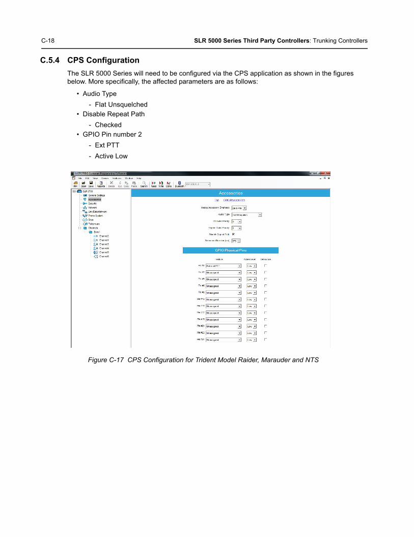
C-18 SLR 5000 Series Third Party Controllers: Trunking Controllers
C.5.4 CPS Configuration
The SLR 5000 Series will need to be configured via the CPS application as shown in the figures below. More specifically, the affected parameters are as follows:
• Audio Type
- Flat Unsquelched
• Disable Repeat Path
- Checked
• GPIO Pin number 2
- Ext PTT
- Active Low
Figure C-17 CPS Configuration for Trident Model Raider, Marauder and NTS

SLR 5000 Series Third Party Controllers: Trunking Controllers C-19
C.5.5 Trunking Controller Settings
The input and output levels should be adjusted per the trunking controller’s instructions. The summary below gives a brief overview of the high level characteristics and trunking controller settings for configuration with the SLR 5000 Series Repeater.
C.5.5.1 Discriminator
The SLR 5000 Series Repeater’s Receiver audio will yield 330 mV rms into 50 kΩ with an RF input signal deviating at 60% RSD. With the trunking controllers own loading impedance, the “Discriminator” signal delivered to the trunking controller will need to be boosted by setting the following jumpers in the noted position:
• Marauder and Raider
- W22: OUT position
- W30: IN position
C.5.5.2 Tx Audio
The SLR 5000 Series Repeater’s transmitter will yield 60% RSD with 80 mV rms into the Emph Tx Audio port. No range setting is provided in the trunking controller for the Tx Audio, rather the level is solely controlled by a singular potentiometer or soft-potentiometer.
C.5.5.3 Tx Data
The SLR 5000 Series Repeater’s transmitter will yield 60% RSD with 80 mV rms into the Tx Data port. No range setting is provided in the trunking controller for the Tx Data, rather the level is solely controlled by a singular potentiometer or soft-potentiometer.
• Marauder, Raider and NTS
- Data needs to be inverted
- NTS needs to be set for DSP operation (Channel card setting)

C-20 SLR 5000 Series Third Party Controllers: Trunking Controllers
Note
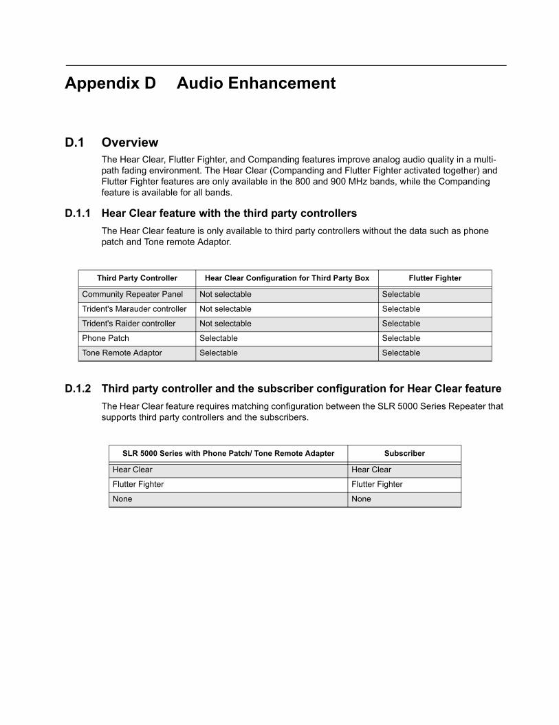
Appendix D Audio Enhancement
D.1 OverviewThe Hear Clear, Flutter Fighter, and Companding features improve analog audio quality in a multi-path fading environment. The Hear Clear (Companding and Flutter Fighter activated together) and Flutter Fighter features are only available in the 800 and 900 MHz bands, while the Companding feature is available for all bands.
D.1.1 Hear Clear feature with the third party controllers
The Hear Clear feature is only available to third party controllers without the data such as phone patch and Tone remote Adaptor.
D.1.2 Third party controller and the subscriber configuration for Hear Clear feature
The Hear Clear feature requires matching configuration between the SLR 5000 Series Repeater that supports third party controllers and the subscribers.
Third Party Controller Hear Clear Configuration for Third Party Box Flutter Fighter
Community Repeater Panel Not selectable Selectable
Trident's Marauder controller Not selectable Selectable
Trident's Raider controller Not selectable Selectable
Phone Patch Selectable Selectable
Tone Remote Adaptor Selectable Selectable
SLR 5000 Series with Phone Patch/ Tone Remote Adapter Subscriber
Hear Clear Hear Clear
Flutter Fighter Flutter Fighter
None None
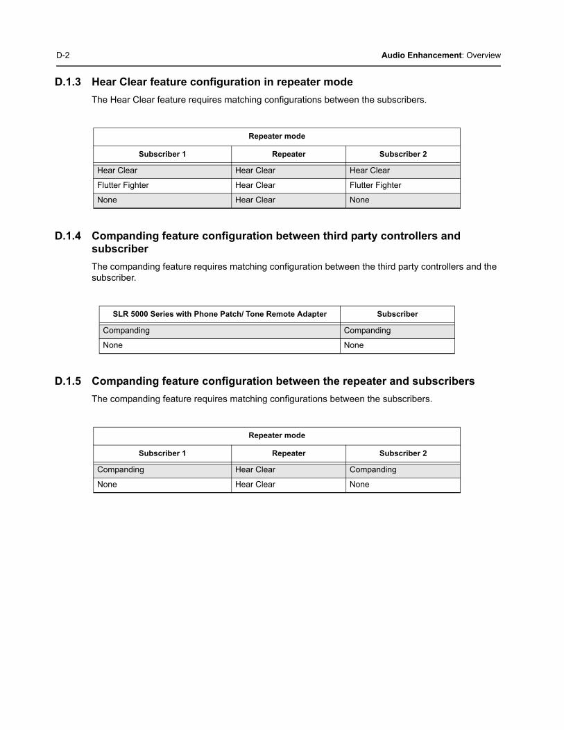
D-2 Audio Enhancement: Overview
D.1.3 Hear Clear feature configuration in repeater mode
The Hear Clear feature requires matching configurations between the subscribers.
D.1.4 Companding feature configuration between third party controllers and subscriber
The companding feature requires matching configuration between the third party controllers and the subscriber.
D.1.5 Companding feature configuration between the repeater and subscribers
The companding feature requires matching configurations between the subscribers.
Repeater mode
Subscriber 1 Repeater Subscriber 2
Hear Clear Hear Clear Hear Clear
Flutter Fighter Hear Clear Flutter Fighter
None Hear Clear None
SLR 5000 Series with Phone Patch/ Tone Remote Adapter Subscriber
Companding Companding
None None
Repeater mode
Subscriber 1 Repeater Subscriber 2
Companding Hear Clear Companding
None Hear Clear None

Appendix E MOTOTRBO Repeater – EME ASSESSMENT
E.1 Executive SummaryThe Electromagnetic Energy (EME) compliance boundaries in a typical system configuration of the Motorola MOTOTRBO SLR 5000 Series Repeater described in the following are derived.
Compliance is established with respect to the applicable limits defined in the ICNIRP guidelines [1], the United States regulations [2]-[3], and in the CENELEC Standards EN50384:2002 [5] and EN50385:2002 [6]. These standards and regulations apply to occupational and general public EME exposure.
The assessment was carried out using a computational method described in the CENELEC Standard EN50383:2010 [4], which is referenced by the EN50385:2002, and this report has been drafted in accordance with its requirements. Thus the assessment and report address the European Radio and Telecommunications Terminal Equipment (R&TTE) Directive requirements concerning EME exposure.
The following table provides the compliance distances for general public and occupational-type exposure, for the UHF frequency band, antenna, and parameters considered in this analysis, based on a typical system configuration:
E.2 Exposure Prediction Model
E.2.1 Exposure in Front of the Antenna
The cylindrical-wave model defined in Clause 8.3.4 of the EN50383:2010 standard is applied to determine the compliance boundaries for workers and general public for a typical system configuration of the MOTOTRBO SLR 5000 Series Repeater.
Note The example given in this Appendix applies for a UHF band system. For different frequencybands, applicable band-specific parameters should be employed to carry out thecomputations yielding band-specific compliance boundaries.
Table E-1 EME Compliance Distances Based on Example UHF Evaluation
Compliance distancesAntenna front
(Andrew mod. DB408)Ground level
(20 m below antenna)
General public exposure 6.9 m Always compliant
Occupational-type exposure 2.15 m Always compliant
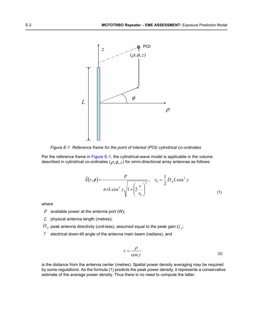
E-2 MOTOTRBO Repeater – EME ASSESSMENT: Exposure Prediction Model
Figure E-1 Reference frame for the point of interest (POI) cylindrical co-ordinates
Per the reference frame in Figure E-1, the cylindrical-wave model is applicable in the volume described in cylindrical co-ordinates ( ) for omni-directional array antennas as follows:
where
available power at the antenna port (W);
physical antenna length (metres);
peak antenna directivity (unit-less), assumed equal to the peak gain ;
electrical down-tilt angle of the antenna main beam (radians), and
is the distance from the antenna center (metres). Spatial power density averaging may be required by some regulations. As the formula (1) predicts the peak power density, it represents a conservative estimate of the average power density. Thus there is no need to compute the latter.
ρ
φ
z POI
L
),,( zφρ
),, zφρ
(1)
P
(2)
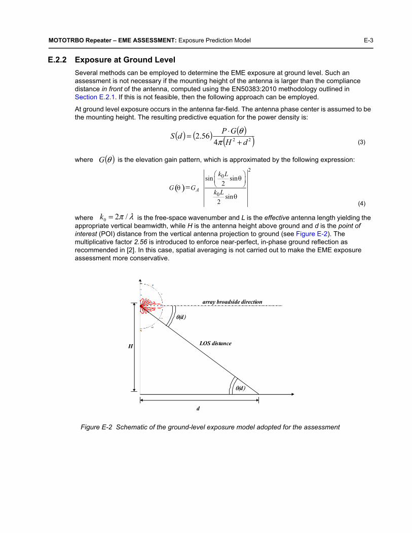
MOTOTRBO Repeater – EME ASSESSMENT: Exposure Prediction Model E-3
E.2.2 Exposure at Ground Level
Several methods can be employed to determine the EME exposure at ground level. Such an assessment is not necessary if the mounting height of the antenna is larger than the compliance distance in front of the antenna, computed using the EN50383:2010 methodology outlined in Section E.2.1. If this is not feasible, then the following approach can be employed.
At ground level exposure occurs in the antenna far-field. The antenna phase center is assumed to be the mounting height. The resulting predictive equation for the power density is:
where is the elevation gain pattern, which is approximated by the following expression:
where is the free-space wavenumber and L is the effective antenna length yielding the appropriate vertical beamwidth, while H is the antenna height above ground and d is the point of interest (POI) distance from the vertical antenna projection to ground (see Figure E-2). The multiplicative factor 2.56 is introduced to enforce near-perfect, in-phase ground reflection as recommended in [2]. In this case, spatial averaging is not carried out to make the EME exposure assessment more conservative.
Figure E-2 Schematic of the ground-level exposure model adopted for the assessment
( ) ( ) ( )( )224
56.2dH
GPdS+
⋅=π
θ(3)
( )θG
(4)
λπ /20 =k
d
H
θ(d)
array broadside direction
LOS distance
θ(d)

E-4 MOTOTRBO Repeater – EME ASSESSMENT: Typical System Configuration
E.3 Typical System ConfigurationThe MOTOTRBO SLR 5000 Series Repeater operates in different frequency ranges with different channels transmitting 100 W radio frequency (RF) power. The typical system configuration comprises an omnidirectional array antenna featuring 6–10 dBd gain, installed at or above 20 m from ground level, and fed by the SLR 5000 Series Repeater through a combiner characterized by a typical 3 dB transmission loss, and a 30 m 7/8” coaxial cable characterized by a typical 2.7 dB/100m loss, resulting in a total 3.9 dB transmission loss. Based on these characteristics, the RF power at the antenna input is about 200 W.
Since shorter antennas provide a conservative EME exposure assessment from equation (1), when , the parameters of a typical 6.6 dBd antennas are employed (it will have to be verified that the
resulting compliance distances are indeed smaller than ). Such an antenna (e.g., Andrew DB408) would exhibit a typical elevation beamwidth of about 14 degrees.
E.4 Exposure LimitsBased on the SLR 5000 Series operating frequency range, the most conservative power density limits are those defined in the ICNIRP guidelines [1]. They are 10.1 W/m2 for occupational exposure, and 2.02 W/m2 for general public exposure. They will be used for the EME exposure assessment.
E.5 EME Exposure Evaluation
E.5.1 Exposure in Front of the Antenna
The assessment is based on the following characteristics of the Andrew DB408 antenna:
The parameter is thus . Upon inserting the power density limits established in Section E.4 into formula (1), the following distances for occupational and general public exposure compliance are respectively determined:
and
As both these distances are less than , the aforementioned choice (Section E.3) of considering the shorter, lower gain antenna to perform the assessment is deemed valid. Longer, higher gain antennas would yield shorter compliance distances, for the same input antenna power and operating frequency range.
E.5.2 Exposure at Ground Level
Since the antenna installation height above ground level in the typical system configuration (20 m) is larger than either of the compliance distances determined in Section E.5.1, the EME exposure at ground level is always compliant with the exposure limits defined in the ICNIRP guidelines.
6.6+2.15
GA = 10 10 = 7.5 P = 200 W γ = 0 L = 2.7 m

MOTOTRBO Repeater – EME ASSESSMENT: Compliance Boundary Description E-5
E.6 Compliance Boundary DescriptionBased on the analysis in Section E.5, the compliance boundaries for occupational and general public exposure are defined as cylinders enclosing the antenna (see Figure E-3), extending 75 cm (one wavelength) above and below the physical antenna, with radii:
Occupational exposure:
General Public exposure:
Figure E-3 Compliance boundary for general public (GP) and occupational (OCC) exposure
E.7 Product Put In ServiceSome regulations require that additional exposure assessments be performed when putting the product in service, to account for antenna site-specific circumstances such as the environment (e.g. electromagnetic scatterers) and other antennas. In such cases, certain standards [7]–[10] may need to be considered to determine the most suitable compliance assessment methodology.
mOCC 15.2=ρ
mGP 9.6=ρ
OCC GP / ρ

E-6 MOTOTRBO Repeater – EME ASSESSMENT: References
E.8 References1. International Commission on Non-Ionizing Radiation Protection (ICNIRP), “Guideline for
Limiting Exposure to Time-Varying Electric, Magnetic, and Electromagnetic Fields,” Health Physics, vol. 74, no. 4, pp. 494-522, April 1998.
2. United States Federal Communication Commission, “Evaluating compliance with FCC guidelines for human exposure to radio frequency electromagnetic fields,” OET Bulletin 65, Ed. 97-01, Section 2 (Prediction Methods), August 1997.
3. US Code of Federal Regulations, Title 47, Volume 1, Sec. 1.1310 Radio frequency radiation exposure limits (Revised as of October 1, 2003). http://edocket.access.gpo.gov/cfr_2003/octqtr/47cfr1.1310.htm.
4. EN 50383:2010. Basic standard for the calculation and measurement of electromagnetic field strength and SAR related to human exposure from radio base stations and fixed terminal stations for wireless telecommunication systems (110 MHz – 40 GHz). CENELEC (European Committee for Electrotechnical Standardization).
5. EN 50384:2002. Product standard to demonstrate the compliance of radio base stations and fixed terminal stations for wireless telecommunication systems with the basic restrictions or the reference levels related to human exposure to radio frequency electromagnetic fields (110 MHz – 40 GHz). Occupational. CENELEC (European Committee for Electrotechnical Standardization).
6. EN 50385:2002. Product standard to demonstrate the compliance of radio base stations and fixed terminal stations for wireless telecommunication systems with the basic restrictions or the reference levels related to human exposure to radio frequency electromagnetic fields (110 MHz – 40 GHz). General public. CENELEC (European Committee for Electrotechnical Standardization).
7. EN 50401:2006. Product standard to demonstrate the compliance of fixed equipment for radio transmission (110 MHz – 40 GHz) intended for use in wireless telecommunication networks with the basic restrictions or the reference levels related to general public exposure to radio frequency electromagnetic fields, when put into service. CENELEC (European Committee for Electrotechnical Standardization).
8. EN 50400:2006. Basic standard to demonstrate the compliance of fixed equipment for radio transmission (110 MHz – 40 GHz) intended for use in wireless telecommunication networks with the basic restrictions or the reference levels related to general public exposure to radio frequency electromagnetic fields, when put into service. CENELEC (European Committee for Electrotechnical Standardization).
9. EN 50492:2008. Basic standard for the in-situ measurement of electromagnetic field strength related to human exposure in the vicinity of base stations. CENELEC (European Committee for Electrotechnical Standardization).
10. IEC 62232:2011. Determination of RF field strength and SAR in the vicinity of radiocommunication base stations for the purpose of evaluating human exposure. IEC (International Electrotechnical Commission).

Glossary of Terms and Acronyms Glossary
This glossary contains an alphabetical listing of terms and their definitions that are applicable to repeater products. All terms do not necessarily apply to all radios, and some terms are merely generic in nature.
Term Definition
Alert tone Audio signal produced by the station, providing feedback to the user.
Analog Refers to a continuously variable signal or a circuit or device designed tohandle such signals.
ASIC Application Specific Integrated Circuit
AUX Auxiliary
Band Frequencies allowed for a specific purpose.
CTCSS Continuous Tone-Controlled Squelch Systems (PL)
Clear Channel modulation type in which voice information is transmitted over the channel using analog modulation.
Conventional Term used for standard non-trunked radio system (usually using TRC/DC console).
CPS Customer Programming Software: Software with a graphical user interfacecontaining the feature set of a radio.
Default A pre-defined set of parameters.
Digital Refers to data that is stored or transmitted as a sequence of discrete symbolsfrom a finite set; most commonly this means binary data represented usingelectronic or electromagnetic signals.
DPL Digital Private-Line: A type of digital communications that utilizes privacy call, as well as memory channel and busy channel lock out to enhance communication efficiency.
DSP Digital Signal Processor, microprocessor specifically designed to perform digital signal processing algorithms.
EIA Electronic Industries Association
ESD Electro Static Discharge
EU European Union
FCC Federal Communications Commission.
FM Frequency Modulation
Frequency Number of times a complete electromagnetic-wave cycle occurs in a fixed unitof time (usually one second).
FRU Field Replaceable Unit

Glossary-2 Glossary of Terms and Acronyms
FSK Frequency Shift Keying
GNSS Global Navigation Satellite System
GPIO General Purpose Input/ Output
IC Integrated Circuit, An assembly of interconnected components on a small semiconductor chip, usually made of silicon. One chip can contain millions omicroscopic components and perform many functions.
IF intermediate frequency
I/O Input or Output
kHz kilohertz: One thousand cycles per second. Used especially as aradio-frequency unit.
LCD Liquid-Crystal Display: An LCD uses two sheets of polarizing material with aliquid-crystal solution between them. An electric current passed through theliquid causes the crystals to align so that light cannot pass through them.
LED Light Emitting Diode: An electronic device that lights up when electricity ispassed through it.
MDC Motorola Data Communications. 1200 or 4800 baud data signalling scheme.
MHz Megahertz: One million cycles per second. Used especially as aradio-frequency unit.
MISO Master In, Slave Out.
MOSI Master Out, Slave In.
PA Power Amplifier that transmits final RF signal to transmit antenna
PC Board Printed Circuit Board. Also referred to as a PCB.
PFC Power Factor Correction
PL Private-Line Tone Squelch: A continuous sub-audible tone that is transmitted along with the carrier.
Programming Cable A cable that allows the CPS to communicate directly with the radio using RS232
PTT Push-to-talk; the switch located on the left side of the radio which, when pressed causes the radio to transmit.
Receiver Electronic device that amplifies RF signals. A Receiver separates the audio signal from the RF carrier, amplifies it, and converts it back to the original sound waves.
Repeater Remote transmit/ receive facility that retransmits received signals in order to improve communications range and coverage.
RF Radio Frequency: The portion of the electromagnetic spectrum between audiosound and infrared light (approximately 10 kHz to 10 GHz).
Term Definition
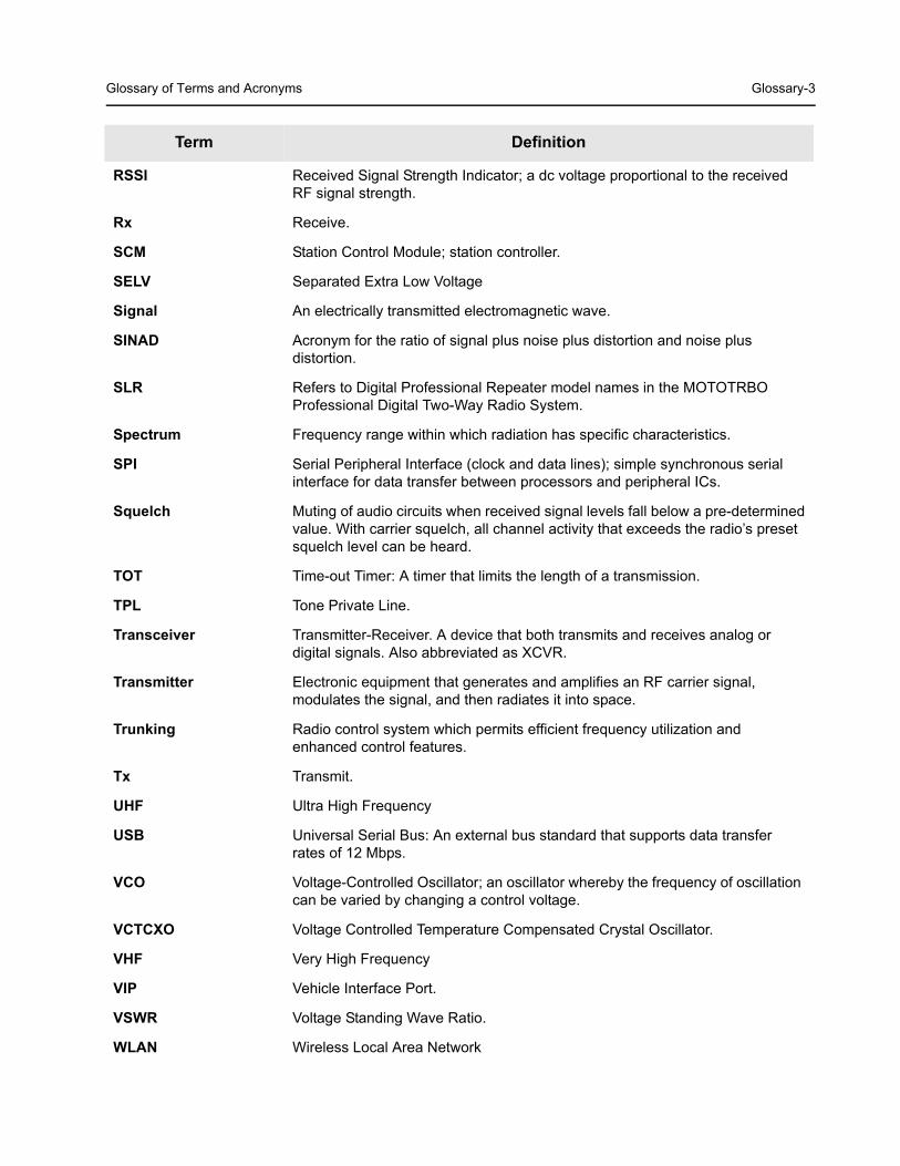
Glossary of Terms and Acronyms Glossary-3
RSSI Received Signal Strength Indicator; a dc voltage proportional to the received RF signal strength.
Rx Receive.
SCM Station Control Module; station controller.
SELV Separated Extra Low Voltage
Signal An electrically transmitted electromagnetic wave.
SINAD Acronym for the ratio of signal plus noise plus distortion and noise plus distortion.
SLR Refers to Digital Professional Repeater model names in the MOTOTRBOProfessional Digital Two-Way Radio System.
Spectrum Frequency range within which radiation has specific characteristics.
SPI Serial Peripheral Interface (clock and data lines); simple synchronous serial interface for data transfer between processors and peripheral ICs.
Squelch Muting of audio circuits when received signal levels fall below a pre-determinedvalue. With carrier squelch, all channel activity that exceeds the radio’s presetsquelch level can be heard.
TOT Time-out Timer: A timer that limits the length of a transmission.
TPL Tone Private Line.
Transceiver Transmitter-Receiver. A device that both transmits and receives analog ordigital signals. Also abbreviated as XCVR.
Transmitter Electronic equipment that generates and amplifies an RF carrier signal,modulates the signal, and then radiates it into space.
Trunking Radio control system which permits efficient frequency utilization and enhanced control features.
Tx Transmit.
UHF Ultra High Frequency
USB Universal Serial Bus: An external bus standard that supports data transferrates of 12 Mbps.
VCO Voltage-Controlled Oscillator; an oscillator whereby the frequency of oscillation can be varied by changing a control voltage.
VCTCXO Voltage Controlled Temperature Compensated Crystal Oscillator.
VHF Very High Frequency
VIP Vehicle Interface Port.
VSWR Voltage Standing Wave Ratio.
WLAN Wireless Local Area Network
Term Definition

Glossary-4 Glossary of Terms and Acronyms
Notes