motorola dsp 56000 core
TRANSCRIPT

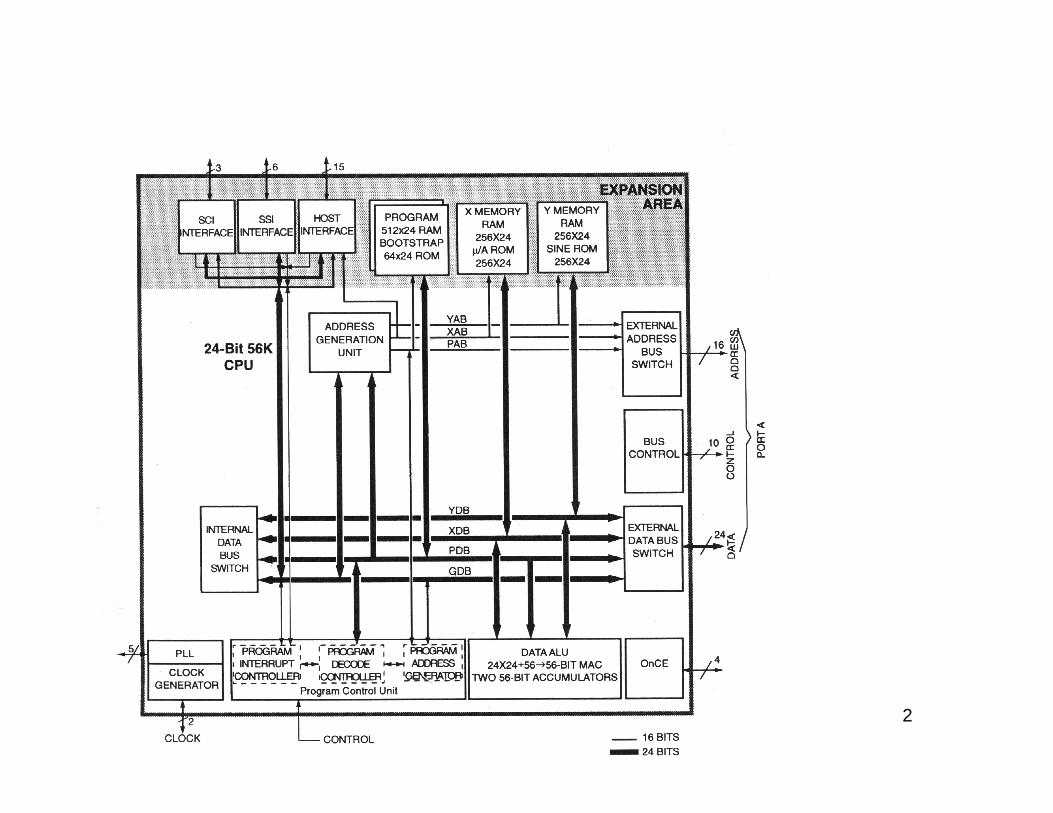
Motorola DSP 56000 Core
• Three independent Execution Units:- Data Arithmetic Logic Unit (data ALU)- Address Generation Unit (AGU)- Program Control Unit (PCU)
• Four independent 24-bit Data Buses:- X Data Bus (XDB)- Y Data Bus (YDB)- Global Data Bus (GDB)
• Three independent 16-bit Address Buses:- X Address Bus (XAB)- Y Address Bus (YAB)- Global Address Bus (GAB)
1
2
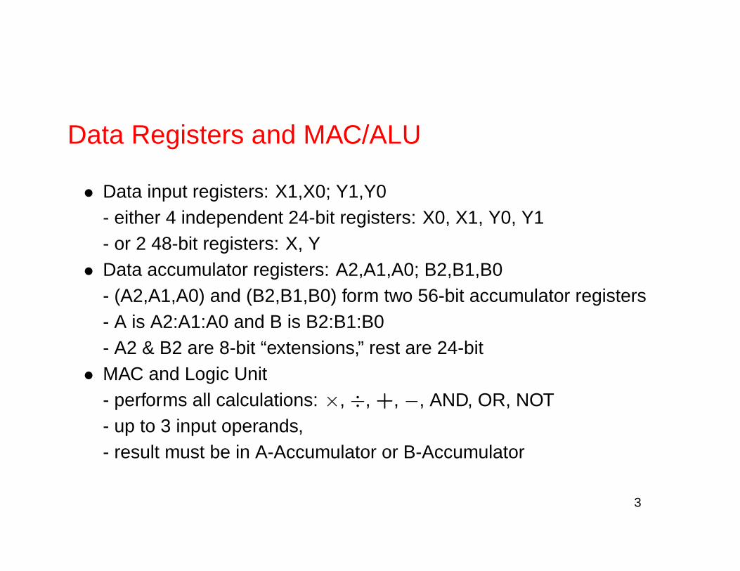
Data Registers and MAC/ALU
• Data input registers: X1,X0; Y1,Y0- either 4 independent 24-bit registers: X0, X1, Y0, Y1- or 2 48-bit registers: X, Y
• Data accumulator registers: A2,A1,A0; B2,B1,B0- (A2,A1,A0) and (B2,B1,B0) form two 56-bit accumulator registers- A is A2:A1:A0 and B is B2:B1:B0- A2 & B2 are 8-bit “extensions,” rest are 24-bit
• MAC and Logic Unit- performs all calculations: ×, ÷, +, −, AND, OR, NOT- up to 3 input operands,- result must be in A-Accumulator or B-Accumulator
3

4

Two’s Complement Fractional Data
• Bit weighting:Word: | − 20 . . .2−23|Long Word: | − 20 . . .2−23|2−24 . . .2−47|Accumulator: | − 28 . . .21|20 . . .2−23|2−24 . . .2−47|
• Example: 0.875 in 24-bit wordHexadecimal: $ 7000000,Binary: %011100000000000000000000= 0×−20 + 1× 2−1 + 1× 2−2 + 1× 2−3
• Example: -0.875 in 24-bit wordHexadecimal: $ 9000000,Binary: %100100000000000000000000= 1×−20 + 1× 2−3
• To convert negative (MSB=1) 2’s complement word to positive: negatebits and add 1- e.g. 100100. . . 00 → 011011. . . 11 → 011100. . . 00
5

MAC and Logic Unit
• addition, subtraction, multiplication• logical AND, OR, NOT, XOR• rounding• left & right shift, up & down scaling• limiting• bit testing and clearing
6

Program Control
• Program Control Register (PC)- 16-bits (24 with upper 8 as 0)- points to Program Memory (P-Memory) of next instruction or imme-diate operand
• Status Register (SR)- 16-bits- MS 8 bits: Mode Register (MR), LS 8: Condition Code Register(CCR)
• System Stack (SS)- separate 32×15 internal memory- stores PC, SR for subroutines, interrupts, looping- can also store LC and LA
• Stack Pointer (SP)- 6 bits: LS 4 bits is pointer, MS 2 bits underflow and error flags
7

• Loop Counter (LC)- 16 bits- # times hardware DO or REPEAT is repeated
• Loop Address Register (LA)- points to last instruction in hardware DO
• Operating Mode Register (OMR)- various modes of DSP

8

9

Address Generation Unit
• 8 16-bit Address Registers R0. . . R7 that point to memory locations• 8 16-bit Offset Registers N0. . . N7 that are added to the respective Rn
to form the final address• 8 16-bit Modifier Registers M0. . . M7 that specify type of arithmetic to
update Address Register
10

11

Modifier Encoding
Modifier Address Arithmetic Type0000 Reverse Carry (Bit Reverse)0001 Modulo 20002 Modulo 3... ...7FFE Modulo 327677FFF Modulo 327688001 Multiple Wrap-around Modulo 28003 Multiple Wrap-around Modulo 22
8007 Multiple Wrap-around Modulo 23
800F Multiple Wrap-around Modulo 24
801F Multiple Wrap-around Modulo 25
... ...9FFF Multiple Wrap-around Modulo 213
BFFF Multiple Wrap-around Modulo 214
FFFF Linear
12
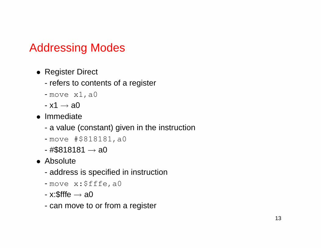
Addressing Modes
• Register Direct- refers to contents of a register- move x1,a0
- x1 → a0• Immediate
- a value (constant) given in the instruction- move #$818181,a0
- #$818181 → a0• Absolute
- address is specified in instruction- move x:$fffe,a0
- x:$fffe → a0- can move to or from a register
13

• Register Indirect- contents of register specifies an address- many flavours to allow many types of indexing
• No Update RI- move b1,y:(r0)- y:(r0) → b1
• Post-increment by One RI- after address is used, add one to register Rn- move b0,y:(r1)+- y:(r1) → b0, r1+1 → r1
• Post-decrement by One RI- after address is used, subtract one from register Rn- move b0,y:(r1)-- y:(r1) → b0, r1-1 → r1
• Pre-decrement by One RI- before address is used, subtract one from register Rn

- move b0,y:-(r1)
- r1-1 → r1, y:(r1) → b0• Post-increment by Offset Nn RI
- after address is used, add register Nn to register Rn- move b0,y:(r1)+n1
- y:(r1) → b0, r1+n1 → r1- also post-decrement
• Indexed with Offset Nn- address is sum of index register Rn and offset register Nn, but Rnremains unchanged- move a1,x(r2+n2)
- x:(r2+n2) → a1

Instruction Set
• Instruction groups: Move, Arithmetic, Logical, Bit Manipulation, Loop,and Program Control
• Many instructions can specify one or two data transfers to be executedin parallel with opcode: “parallel-move” operations
Opcode Operand Xfr X-Bus Xfr Y-Bus XfrMOVE X1,AMOVE X0,X:(R2)-MOVE X0,Y:(R3)+N3RND A X:(R0)+,R0 Y:(R4)+,Y0MAC X0,Y0,B X:(R0)+,R0 Y:(R4)+,Y0ADD X,B X:(R6)+,X1 Y0,Y:(R7)-
14

Parallel-Moves
Parallel-Move Opcode Parallel-MoveOperations Operands ExamplesImmediate ADD B,A #$81,B0Reg. to Reg. ADD B,A X1,B
ADD X1,A B,R0Addr. Reg. update ADD B,A (R1)+N1X or Y Mem ADD A,B A,X:$1000
ADD A,B Y:-(R3),AY or Y Mem & reg ADD X,A A,X:(R3+N3) A,Y1XY Mem ADD X,B X:(R0)+,X1 Y0,Y:(R7)-
15

U=Address Register Update X=X-Memory MoveY=Y-Memory Move X+R=X-Memory & Register MoveY+R=Y-Memory & Register Move XY=XY-Memory Move
X X+RAddressing Modes U Y Y+R XYRegister Direct no no no noAddress Register IndirectNo Update no yes yes yesPostinc 1 yes yes yes yesPostdec 1 yes yes yes yesPostinc Nn yes yes yes yesPostdec Nn yes yes yes noIndex by Nn no yes yes noPredec 1 no yes yes noSpecialImmediate no yes yes noAbsolute no yes yes noImmediate short no no no no
16

Move Instructions
LUA Load updated addressMOVE Move dataMOVEC or MOVE Move control registerMOVEM or MOVE Move program memoryMOVEP Move peripheral data
17

Arithmetic InstructionsABS Absolute value ADC Add with carryADD Add ADDL Shift left then addADDR Shift right then add ASL Arithmetic shift leftASR Arithmetic shift right CLR ClearCMP Compare CMPM Compare MagnitudeDEC Decrement by one DIV Divide IterationINC Increment by one MAC Multiply-accumulateMACR Multiply-accumulate & round MPY MultiplyMPYR Multiply & round NEG NegateNORM Normalize iteration RND RoundSBC Subtract with carry SUB SubtractSUBL Shift left then subtract SUBR Shift right then subtractTcc Transfer conditionally TSF TransferTST Test
18
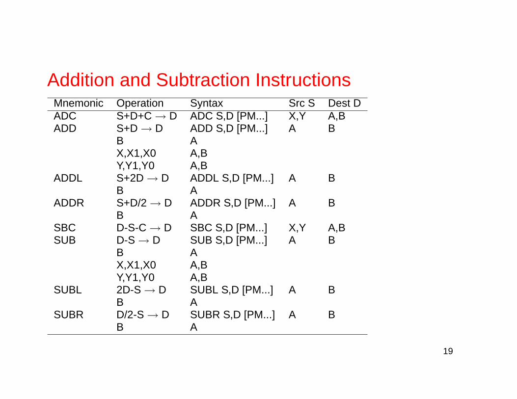
Addition and Subtraction InstructionsMnemonic Operation Syntax Src S Dest DADC S+D+C → D ADC S,D [PM...] X,Y A,BADD S+D → D ADD S,D [PM...] A B
B AX,X1,X0 A,BY,Y1,Y0 A,B
ADDL S+2D → D ADDL S,D [PM...] A BB A
ADDR S+D/2 → D ADDR S,D [PM...] A BB A
SBC D-S-C → D SBC S,D [PM...] X,Y A,BSUB D-S → D SUB S,D [PM...] A B
B AX,X1,X0 A,BY,Y1,Y0 A,B
SUBL 2D-S → D SUBL S,D [PM...] A BB A
SUBR D/2-S → D SUBR S,D [PM...] A BB A
19

Multiply (and Accumulate) InstructionsMnemonic Operation SyntaxMAC D±(S1×S2)→D MAC ±S1,S2,D [PM...]
D±(S1×2−n)→D MAC ±S1,#n,D [PM...]MACR round(D±(S1×S2))→D MACR ±S1,S2,D [PM...]
round(D±(S1×2−n))→D MACR ±S1,#n,D [PM...]MPY ±(S1×S2)→D MPY ±S1,S2,D [PM...]
±(S1×2−n)→D MPY ±S1,#n,D [PM...]MPYR round(±(S1×S2))→D MPYR ±S1,S2,D [PM...]
round(±(S1×2−n))→D MPYR ±S1,#n,D [PM...]
with S1 & S2 being any combination of X0,X1,Y0,Y1
20

Logical Instructions
AND Logical AND ANDI AND immediate control registerEOR Logical exclusive OR LSL Logical shift leftLSR Logical shift right NOT ComplementOR Logical inclusive OR ORI OR immediate control registerROL Rotate left ROR Rotate right
Bit Manipulation Instructions
BCLR Bit test and clear BSET Bit setBCHG Bit test and change BTST Bit test on memory and
21

Program Control Instructions
DO Hardware DO loop ENDO Terminates hardware loopDEBUG Enter debug mode DEBUGcc Enter debug mode conditionallyIll Illegal instruction Jcc Jump conditionallyJMP Jump JCLR Jump if bit clearJSET Jump if bit set JScc Jump to subroutine conditionallyJSR Jump subroutine JSCLR Jump subroutine if bit clearJSSET Jump subroutine if bit set NOP No operationREP Repeat next instruction RESET Reset on-chip peripheralsRTI Return from interrupt RTS Return from subroutineSTOP Stop processing SWI Software interruptWAIT Wait for interrupt
22

Hardware DO examplefor (i=0; i<3; ++i) {
c[i]=a[i]*b[i];}
a is X:$1000, b is Y:$2000, and c is X:$1500
org p:$100move #$1000,r0move #$2000,r4move #$1500,r1move x:(r0),x0move y:(r4),y0do #3,_endloopmpyr x0,y0,a x:(r0)+,x0 y:(r4)+,y0nopmove a,x(r1)+nop
_endloop
23

REP Instruction
Mnemonic Operation SyntaxREP LC → Temp; #xxx → LC REP #xxx
Repeate next instruction until LC = 1 REP X:¡ea¿Temp → LC REP Y:¡ea¿
REP S
Example: filter y[n] =∑M−1
k=0 bkx[n− k]
clr a x0,x:(r1)+ y:(r4)+,y0
rep #ntaps-1
mac x0,y0,a x:(r1)+,x0 y:(r4)+,y0
macr x0,y0,a (r1)-
move a,x0
24
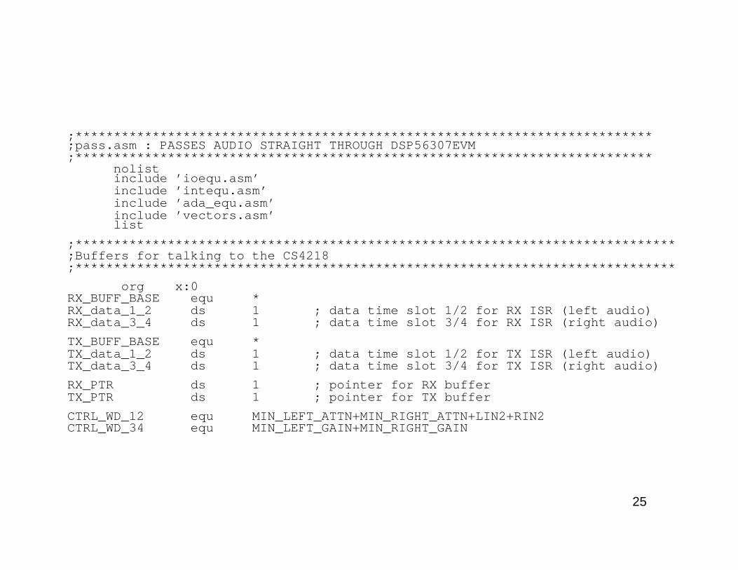
;***************************************************************************;pass.asm : PASSES AUDIO STRAIGHT THROUGH DSP56307EVM;***************************************************************************
nolistinclude ’ioequ.asm’include ’intequ.asm’include ’ada_equ.asm’include ’vectors.asm’list
;******************************************************************************;Buffers for talking to the CS4218;******************************************************************************
org x:0RX_BUFF_BASE equ *RX_data_1_2 ds 1 ; data time slot 1/2 for RX ISR (left audio)RX_data_3_4 ds 1 ; data time slot 3/4 for RX ISR (right audio)
TX_BUFF_BASE equ *TX_data_1_2 ds 1 ; data time slot 1/2 for TX ISR (left audio)TX_data_3_4 ds 1 ; data time slot 3/4 for TX ISR (right audio)
RX_PTR ds 1 ; pointer for RX bufferTX_PTR ds 1 ; pointer for TX buffer
CTRL_WD_12 equ MIN_LEFT_ATTN+MIN_RIGHT_ATTN+LIN2+RIN2CTRL_WD_34 equ MIN_LEFT_GAIN+MIN_RIGHT_GAIN
25

;******************************************************************************;Main Program;******************************************************************************
org p:$400START
movep #$040006,x:M_PCTL ; PLL 7 X 12.288 = 86.016MHzmovep #$012421,x:M_BCR ; AARx - 1 wait stateori #3,mr ; mask interruptsmovec #0,sp ; clear hardware stack pointermove #0,omr ; operating mode 0move #$40,r6 ; initialise stack pointermove #-1,m6 ; linear addressingjsr ada_init ; initialize codec
loopjset #3,x:M_SSISR0,* ; wait for RX frame syncjclr #3,x:M_SSISR0,* ; wait for RX frame sync
move x:RX_BUFF_BASE,a ; receive leftmove x:RX_BUFF_BASE+1,b ; receive right
nop ; pass data straight throughnop
move a,x:TX_BUFF_BASE ; transmit leftmove b,x:TX_BUFF_BASE+1 ; transmit rightjmp loop
include ’ada_init.asm’end