motorized measurement device for automatic registration of
TRANSCRIPT

59th ILMENAU SCIENTIFIC COLLOQUIUM Technische Universität Ilmenau, 11 – 15 September 2017
URN: urn:nbn:de:gbv:ilm1-2017iwk-010:5
©2017 - TU Ilmenau
MOTORIZED MEASUREMENT DEVICE FOR AUTOMATIC REGISTRATION OF CUTTING EDGES
Bernd-Arno Behrens, Richard Krimm, Quoc Thang Nguyen
Institute of Forming Technology and Machines Leibniz University Hannover
ABSTRACT
Sheet metal products can be found in almost all household-, electrical appliances, vehicles and industrial machines. One of the widely spread methods of sheet metal processing is the shearing process which separates large sheets into smaller sections (stampings) for subsequent operations. Cutting edges of stampings are substantial for the evaluation of the product quality. For this purpose the significant parameters of cutting edges such as rollover, burnish, fracture and burr are standardized in VDI norm 2906. Currently, the most popular methods of evaluation of cutting edges are metallography, confocal microscopy and tactile measuring systems, which are still time-consuming and cost-intensive, since the stamped parts need to be analyzed by qualified personnel. This work is based on objectives aimed at developing a motorized measurement device, which registry edge profiles automatically by means of optical sensors and calculate parameters of cutting edges by means of an algorithm. Therefore no specific knowledges of user are required for the evaluation.
Index Terms – shear cutting, cutting edges, high precision measurement
1. INTRODUCTION
Shearing process is a sheet metal processing method, in which millions of stampings can be produced within a relative short period of time by means of a cutting tool and a mechanical press with high stroke rate up to 1000 strokes per min [1]. From the economic point of view this process is most suitable for large-scale production and is therefore widely spread in the metal industry [2]. The shearing process can be generally divided in four phases: (s. Fig. 1) [3]: • (a) just before punch• (b) plastic deformation: the punch comes in contact with sheet metal and transmits the
press force on the sheet metal’s surface• (c) penetration: the plastic forming capacity is exceed, the punch penetrates into sheet
metal and causes cracks• (d) fracture: Sheet metal is completely separated by the punch. The sudden discharge
of the press (so called cutting shock) results in high frequently vibrations in bothcutting tool and machine.
Shear cutting is often used to separate materials into smaller parts. Two most popular variants of the shearing process are blanking and punching. In blanking the sheet metal (blank part) is separated from surrounding stock, while in punching the scrap is to divide (Fig. 1).

©2017 - TU Ilmenau 2
Fig. 1: four phases of shearing process (a-d) and stamping products
The blank part contains characteristic cutting edges, which is typical for products of shearing process. To evaluate the quality of cutting edges standardized parameters are defined in VDI norm 2906 (Fig. 2) [4]. The most important parameters for the evaluation are burnish and burr. In most cases a maximal burnish depth and a minimum burr height are desirable for the best product quality.
Fig. 2: cutting edge parameters according to VDI norm 2906
2. SOLUTION APPROACH
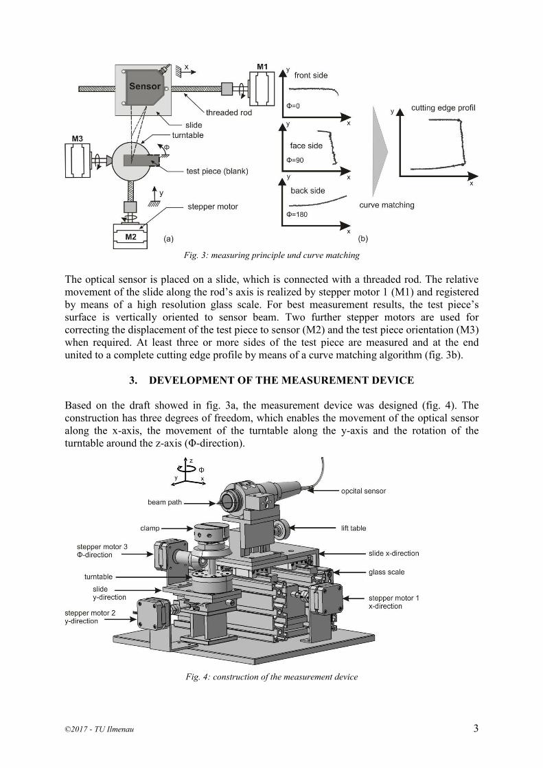
Currently, cutting edges are measured by means of confocal microscopes, tactile systems and especially metallography. When using the last mentioned method, grinding pattern of the test piece has to be created and analyzed under microscope to determine the cutting edge parameters, which is very time-consuming and cost-intensive. In this work, a motorized device for automatic registration of cutting edges is developed to reduce the process chain of the cutting edge evaluation. The use of a high-precision confocal chromatic sensor enables the measurement of displacement between sensor and test piece and thus also the cutting edges profile. In Fig. 3 the measuring principle is illustrated.
©2017 - TU Ilmenau 3
Fig. 3: measuring principle und curve matching
The optical sensor is placed on a slide, which is connected with a threaded rod. The relative movement of the slide along the rod’s axis is realized by stepper motor 1 (M1) and registered by means of a high resolution glass scale. For best measurement results, the test piece’s surface is vertically oriented to sensor beam. Two further stepper motors are used for correcting the displacement of the test piece to sensor (M2) and the test piece orientation (M3) when required. At least three or more sides of the test piece are measured and at the end united to a complete cutting edge profile by means of a curve matching algorithm (fig. 3b).
3. DEVELOPMENT OF THE MEASUREMENT DEVICE Based on the draft showed in fig. 3a, the measurement device was designed (fig. 4). The construction has three degrees of freedom, which enables the movement of the optical sensor along the x-axis, the movement of the turntable along the y-axis and the rotation of the turntable around the z-axis (Φ-direction).
Fig. 4: construction of the measurement device

©2017 - TU Ilmenau 4
Three stepper motors are used to perform the movements in x-,y- and Φ direction. This type of engine is most suitable for positioning tasks due to its stepwise working principle. In general one 360 degree rotation corresponds to 200 steps of one stepper motor. If the microstep resolution is adjusted to 6, then one rotation is corresponding to 12800 micro steps (2^6*200), which enables a positioning accuracy of about 0,028 degree. With thread pitches of 2mm/rev along the x-axis and 4,2mm/rev along the y-axis, this construction has a positioning accuracy of about 0,05mm in x-direction and 0,11mm in y-direction. To register the relative movement of the laser sensor along the x-axis, a glass scale with an increment step of 0,5 μm is used. The confocal chromatic sensor in use is of IFS2405-3 type with 3mm measuring range and measurement accuracy up to 36 nm [5]. For the automatic measurement of cutting edges a control circuit is to designed, which synchronizes the movement of three stepper motors. A TMCM-351 board is used as three axes stepper motor driver. This module contains a microcontroller Atmel AT91SAM7X256, which executes commands sending from host computer via serial interface RS232, RS485, USB or CAN to the module. The commands for motor motion and parameter setting such as motor current, speed and microstep resolution are deposited in a library with the Trinamic Motion Control Language (TMCL) [6]. In case the module is connected with the host computer via RS232 or RS485 interface, the commands have to be converted from TMCL in binary format. A binary command format has 9 bytes consisting of 1 byte module address, 1 byte command number, 1 byte type number, 1 byte motor number, 4 byte value and 1 byte checksum. Every time a command has sent to the module, the host computer receives a reply format, which also contains 9 byte (Fig. 5). The status byte in the reply provides information on whether the command is successfully executed or not. The checksum byte is calculated by adding all the other bytes using 8-bit addition.
Fig. 5: command, reply format and status codes [5]
The control circuit was developed in the commercial software environment Matlab and has to complete two tasks: on one hand, to create driving profiles for stepper motors by converting and sending commands to control module and on other hand, to process measurement signals of confocal sensor and glass scale. The connection diagram of control module, sensors and host computer is illustrated in fig. 6. A controller of type IFC2422 is used as light source. Moreover, the controller suppresses the fluctuations of the sensor signals by obtaining the mean value. The glass scale is connected to the encoder input of the controller, therefore no further measuring card is required. The controller sends data packages in binary format, which

©2017 - TU Ilmenau 5
include the processed sensor signals, the intensity of the signals and the encoder values, via Ethernet to the host computer.
Fig. 6: Connection diagram
4. CURVE MATCHING METHOD
To register the geometry of cutting edges as illustrated in fig. 7, at least three sides of the testing part are to measure. First the measuring curves of three sides are available in the local coordinate systems, which consist of encoder values in x-axis and displacement values of optical sensor in y-axis. Before these three curves are merged to one complete contour, they need to be transformed in the global coordinate system by means of equation 1.1:
(𝒙𝒚)
𝒈𝒍𝒐𝒃𝒂𝒍= 𝑹 ∗ (
𝒙𝒚)
𝒍𝒐𝒄𝒂𝒍 1.1
R is the 2x2 rotation matrix, which is defined as 𝑅𝑥,𝛼 = (𝑐𝑜𝑠 𝛼 −𝑠𝑖𝑛 𝛼𝑠𝑖𝑛 𝛼 𝑐𝑜𝑠 𝛼
) for the rotation
around x axis, 𝑅𝑦,𝛽 = (𝑐𝑜𝑠 𝛽 𝑠𝑖𝑛 𝛽
−𝑠𝑖𝑛 𝛽 𝑐𝑜𝑠 𝛽) for the rotation around y axis and 𝑅𝑧,𝛿 =
(𝑐𝑜𝑠 𝛿 −𝑠𝑖𝑛 𝛿𝑠𝑖𝑛 𝛿 𝑐𝑜𝑠 𝛿
) for the rotation around z axis. To combine the three measuring curves to one, an algorithm for curve matching is needed. Its function is to distinguish the regions of these three curves, which correspond most to each other. Methods of comparison curve shapes based on theirs curvature and arc-length [7] are most suitable for differentiable curves with large curvature. These methods don’t work reliably at identifying the similar regions of cutting edges due to the relative small curvature. To solve this problem, a new method was developed based on the number of intersection points of the comparing curves. In fig. 8 the basic operations are illustrated to match curve 2 and 3 of the cutting edge geometry.

©2017 - TU Ilmenau 6
Fig. 7: Coordinate transformation
To find this best matching positon, curve 2 was shifted along curve 3. For every position of curve 2, the number of intersection points between these two curves is calculated. Two comparing curves match to each other best, if they have the most intersection points. The optimization problem to solve is showed below, while x and y are the coordinates of the intersection points:
arg max 𝑓(𝑥, 𝑦) ≔ ∑{‖𝑥1𝑖 − 𝑥2𝑖‖ < 0,5} & {‖𝑦1𝑖 − 𝑦2𝑖‖ < 0,5}
𝑛
𝑖=1
In this case, the best matching of curve 2 and 3 is showed in the middle graph of fig. 8. At this positon, the greatest possible number of intersections is 50. In the same way, the best matching of curve 1 and 2 can be found by shifting one curve along the other.
Fig. 8: matching of curve 2 and 3

©2017 - TU Ilmenau 7
Once all similar regions are identified, three curves can be united to one, where the first intersection point of curve 1 and 2 is the beginning of curve 2 and the first intersection point of curve 2 and 3 is the beginning of curve 3 (fig. 9).
Fig. 9: fusion of curve 1,2 and 3
5. MEASUREMENT RESULTS
To control the accuracy of the developed optical measurement method, three testing parts of different materials, which were produced by stamping process, were first measured by the confocal chromatic sensor and then compared with the metallographic examinations (fig. 10, 11, 12). For each testing part, three measurements, which are assigned to three cutting edges geometries, were performed. The measurement results show high degree of correspondence with the metallographic examinations. Despite the difference surface properties of the testing parts, the significant parameters of cutting edge such as rollover, burr, burnish and fracture are correctly identified.
Fig. 10: cutting edges of testing part DC04
©2017 - TU Ilmenau 8
Fig. 11: cutting edges of testing part DP6
Fig. 12: cutting edges of testing part X5CrNi18-10
6. SUMMARY
Sheet metal products are available in most machines, vehicles and household appliances. The cutting edge geometries of those products are the most significant indicator of their qualities. Currently, the methods of cutting edge analyzing are still cost and time consuming due to the long process chain of evaluation and the requirement of qualified personnel. In this paper, a
©2017 - TU Ilmenau 9
new method of cutting edge evaluation based on optical sensor is introduced. By means of a motorized mechanical system equipped with a high-precision chromatic sensor, geometries of cutting edges, regardless of materials with different surface properties, can be automatically registered within relative short time. In comparison with the metallography method, which is already established in practice, the measurement results show high degree of correspondence. Acknowledgement
The IGF-project 19081N of the European Research Association for Sheet Metal Working (EFB) is supported via the German Federation of Industrial Research Associations (AiF) within the framework of the Industrial Collective Research (IGF) program by the Federal Ministry of Economics and Technology on the basis of a decision by the German Bundestag. The Authors would like to thank the EFB and the members of the industrial consortium for supporting the research activities.
7. REFERENCES [1] Doege, E.; Behrens, B.-A.: Handbuch Umformtechnik: Grundlagen, Technologien,
Maschinen, Springer-Verlag, Berlin Heidelberg, 2007 [2] Neugebauer, R.; Putz, M.; Bränlich, H.; Kräsel, V.: "Schneiden und Lochen- ein
Entwicklungsorientierter Bereich der Blechverarbeitung", Internationale Konferenz "Neue Entwicklung in der Blechumformung" in Fellbach, 11. und 12. Mai, 2004
[3] Zhu, Y.: MSE 400/540: Processing of Metallic Materials, Lecture 12: Cutting (Shearing) and Bending, Department of Materials Science and Engineering, NC State University
[4] N.N.: „VDI-Richtlinie 2906: Schnittflächenqualität beim Schneiden, Beschneiden und Lochen von Werkstücken aus Metall“, Düsseldorf, VDI-Verlag, 1994
[5] Micro Epsilon Messtechnik GmbH& Co. KG: Betriebsanleitung optoNCDT 2300, 2008
[6] Trinamic Motion Control: TMCL Reference and Programming Manual, Version 2.22, 2008
[7] Femiani, J.C.; Razdan, A.;Cui, M.; Hu, J.; Wonka, P.: Curve Matching for Open 2D Curves, June 4, Nation Science Foundation, 2009
CONTACTS Prof. Dr. -Ing. Bernd –Arno Behrens [email protected] Dr. -Ing. Richard Krimm [email protected] M. Sc. Quoc Thang Nguyen [email protected]