motorization of a surgical microscope for intra-operative navigation and intuitive control
TRANSCRIPT
THE INTERNATIONAL JOURNAL OF MEDICAL ROBOTICS AND COMPUTER ASSISTED SURGERYInt J Med Robotics Comput Assist Surg 2010; 6: 269–280. ORIGINAL ARTICLEPublished online 28 April 2010 in Wiley Online Library (wileyonlinelibrary.com) DOI: 10.1002/rcs.314
Motorization of a surgical microscope forintra-operative navigation and intuitive control
M. Finke*A. Schweikard
Institute for Robotics and CognitiveSystems, University of Lubeck,Germany
*Correspondence to: M. Finke,Institute for Robotics and CognitiveSystems, University of Lubeck,Ratzeburger Allee 160, 23538Lubeck, Germany. E-mail:[email protected]
Accepted: 23 March 2010
Abstract
Background During surgical procedures, various medical systems, e.g.microscope or C-arm, are used. Their precise and repeatable manualpositioning can be very cumbersome and interrupts the surgeon’s work flow.Robotized systems can assist the surgeon but they require suitable kinematicsand control. However, positioning must be fast, flexible and intuitive.
Methods We describe a fully motorized surgical microscope. Hardwarecomponents as well as implemented applications are specified. The kinematicequations are described and a novel control concept is proposed.
Results Our microscope combines fast manual handling with accurate,automatic positioning. Intuitive control is provided by a small remotecontrol mounted to one of the surgical instruments. Positioning accuracyand repeatability are <1 mm and vibrations caused by automatic movementsfade away in about 1 s.
Conclusion The robotic system assists the surgeon, so that he can positionthe microscope precisely and repeatedly without interrupting the clinicalworkflow. The combination of manual und automatic control guarantees fastand flexible positioning during surgical procedures. Copyright 2010 JohnWiley & Sons, Ltd.
Keywords surgical microscope; robotics; computer-assisted surgery;motorization
Introduction
While dedicated robotic systems have been developed for some medicalapplications (e.g. Cyberknife, da Vinci), many conventional medical devicescan benefit from being robotized, because one of the most important featuresassociated with a robotic device is repeatability. Examples include roboticC-arms (1), surgical microscopes (2) and laparoscopic cameras (3).
For neurosurgical procedures, visualization with high resolution of thesurgical field is important because the surgeon has to examine fine structures.Therefore, the microscope is a key tool which has to be positioned frequentlyduring surgery. So far, the surgeon has to manually perform even smallvariations of the field of view. Hence, robotization in combination withadvanced control concepts could directly impact and benefit the clinicalworkflow.
Recently, partially motorized surgical microscopes have been developed,e.g., Zeiss OPMI Neuro/NC4, Leica M520 MC1 or Moller-Wedel HI-R1000.
Copyright 2010 John Wiley & Sons, Ltd.
270 M. Finke and A. Schweikard
The surgeon can tilt the microscope around the twocoordinate axes of the field of view, using the twomotorized axes. The microscope mounting itself staysin the same position and only the viewing direction isvaried. Only limited regions can be approached, whilelarger movements still have to be done manually bythe surgeon. Incomplete motorization, therefore, providesonly limited degrees of freedom to change the orientationof the objective.
One of the problems in clinical practice is the manualoperation of the microscope by the surgeon, whichinterrupts his workflow. For example, each positioningrequires a number of steps. First, the surgeon puts hisinstruments aside. Second, he unlocks the microscope,repositions it and locks it again. Third, he picks up hisinstruments and continues the operation. This sequencemust be undergone even if the visible area is shifted asideonly a few millimeters.
With the Zeiss MKM system (2), accurate, motor-driven positioning became possible in 1993. This systemconsists of an industrial robot arm holding differenttools, e.g. a microscope. Due to limitations in workspaceand dynamics, the MKM was suitable only for openprocedures at the frontal skull base and for neurosurgicalprocedures, while procedures where fast motion andflexible positioning were required could not be performed(4).
The combination of an industrial robot arm and astereo-microscope was also used by Lauer et al. (5). Here,the arm is firmly attached to the operating table. Thevisualization of the operation field is provided to thesurgeon by a head-mounted display (HMD). Both thestationary design of the system and the need to wear anHMD can hamper rapid dismounting during emergenciesand limit usability for the surgeon.
However, a key requirement for a robotized microscopeis that the system works even in an emergency case.For example, if the patient has to be reanimated,the microscope must be moved aside quickly so thatthe reanimation procedure can be started immediately.Likewise, in the case of an unexpected system powerfailure, the microscope needs to be removed from theoperation couch.
Along with a surgeon, we analysed typical motionsof the microscope in clinical practice. We identified twomain categories of movements. On the one hand, there arelong-distance movements that require fast positioning butremain inaccurate. On the other hand, the surgeon movesthe microscope slowly to achieve exact positioning. Forexample, the latter contains translational motions parallelto the current field of view, or pivot movements in orderto observe tissue from different directions.
Robotization is reasonable for movements of the secondcategory because it improves accuracy and enablesapplications that can hardly be done manually. Bycontrast, active movements of the first category wouldeither take a long time or would be risky for peopleclose by.
Hence, a fully robotized microscope should be operableautomatically as well as manually in order to combinelarge, rapid movements and slow, accurate ones.
An intuitive remote control is necessary to enableeasy control of robotized motion tasks. It should providewireless communication, so that handling the remotecontrol does not interrupt the clinical work flow.
Starting from the description of a conventionalmicroscope, we derive the specifications and hardwarerequirements for a robotized surgical microscope. Wedescribe a motion control concept and present akinematical analysis of the system. A number ofapplications present the usability of active movements ofthe microscope. We present results regarding accuracyand dynamics which indicate improved operabilityand robust positioning for the proposed motorizedmicroscope.
Methods
Microscope
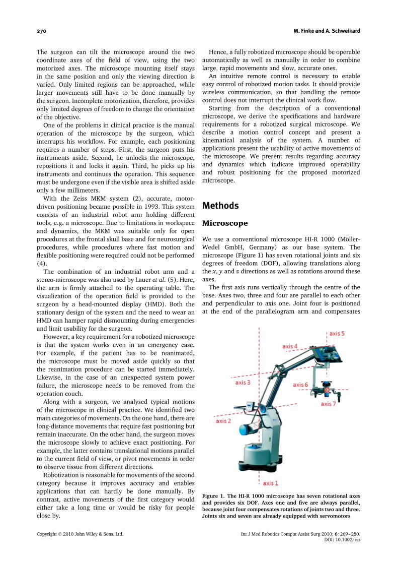
We use a conventional microscope HI-R 1000 (Moller-Wedel GmbH, Germany) as our base system. Themicroscope (Figure 1) has seven rotational joints and sixdegrees of freedom (DOF), allowing translations alongthe x, y and z directions as well as rotations around theseaxes.
The first axis runs vertically through the centre of thebase. Axes two, three and four are parallel to each otherand perpendicular to axis one. Joint four is positionedat the end of the parallelogram arm and compensates
Figure 1. The HI-R 1000 microscope has seven rotational axesand provides six DOF. Axes one and five are always parallel,because joint four compensates rotations of joints two and three.Joints six and seven are already equipped with servomotors
Copyright 2010 John Wiley & Sons, Ltd. Int J Med Robotics Comput Assist Surg 2010; 6: 269–280.DOI: 10.1002/rcs
Motorization of a surgical microscope for intra-operative navigation and intuitive control 271
for the rotations of joints two and three, so that themicroscope suspension (axis five) is always kept parallelto axis one. The last two axes (six and seven) allow tiltand roll movements about the two horizontal main axesof the microscope.
The system comes with joints six and seven alreadymotorized by the vendor. Joint four does not have tobe motorized because the parallel kinematics of theparallelogram arm moves the passive joint, accordingto axes two and three. The remaining axes (1–3 and 5)are equipped with brakes that must be released beforemanual operation.
We integrated an image injection module (LightRouter LR1000i, Moller-Wedel, Germany) into thesurgical microscope. Images coming from the operatingmicroscope can be superimposed with images from anexternal PC or a navigation system, and switched out viashutter.
The microscope is counterbalanced by a weight at thelower end of the parallelogram arm. On the one hand,this simplifies manual handling, as the microscope canbe positioned with minimal force and the surgeon doesnot have to carry its whole weight. On the other hand,the system cannot move unexpectedly if the brakes areunlocked.
The microscope architecture implies a limited work-and configuration space (Table 1). However, the reach-able workspace is approximately 80–200 cm above thefloor and 70–170 cm from axis one. Furthermore, theworking distance between the ocular and surgical fieldscan be varied in the range 22.4–51.0 cm.
Motorization of the microscope
In contrast to existing approaches, we have motorized allaxes of the standard microscope. As mentioned above,it is a key requirement that the microscope can beremoved rapidly from the operation field in case ofan emergency. Hence, we decided to keep the manualfunctions of the microscope as the primary mode andadded automatic control. This means that the microscopecan move automatically only if the brakes of the manual
Table 1. Limitations of the six motorized joints and the optics∗
θ1 (◦) θ2 (◦) θ3 (◦) θ5 (◦) θ6 (◦) θ7 (◦) WD Zoom
Min None −120 30 −270 40 −140 224 ×1.3Max None −40 115 270 210 −45 510 ×15.0
∗θi refers to the angle of rotation about axis i.
mode are fastened. Releasing these brakes disconnects allmotors and stops automatic motion immediately.
Moreover, the actuators should enable slow andaccurate movements in the operation workspace, for tworeasons. First, the diameter of the field of view varies inthe range 14.7–87.1 mm. If the surgeon examines tissuewhile the microscope is moving, the system will shift onlyvery short distances. It must neither oscillate intenselynor blur the surgeon’s view. Second, the surgeon looksthrough the eyepieces even if the system is moving. So,fast and abrupt motions have to be avoided for safetyreasons.
On the one hand, the actuators should achievepositioning accuracy of better than 0.025◦/step and aholding torque of at least 60 Ncm. On the other hand, theintegrated components must be sufficiently small to fit intothe existing system, especially into the parallelogram arm.
We therefore decided to use stepper motors ST5709(Nanotec Electronic GmbH & Co.KG, Germany) for thefirst three axes and ST5918 for axis five, because theycan be easily and reliably controlled via software. Theadvantages of stepper motors compared to servo-motorsare strong holding torques and low inertia. Also, theyare robust, maintenance-free and do not require complexsettings of motor parameters. Gearboxes reduce the stepresolution to 0.018◦/step or less (Table 2).
However, stepper motors can cause inaccuracies,losing single steps. Hence, each axis is equipped withan external encoder, AD36 (Hengstler, Germany), toimprove positioning accuracy. It has a resolution of219 steps/rotation of 360◦ and 212 for the number ofrotations. This corresponds to 0.0007◦/step, which is ahigher resolution than in the motors (Table 2).
In contrast to the motors, the encoders must notbe disconnected from the joints because exact positionneeds to be known, even in manual mode. Hence, themicroscope can also be used for navigation during theoperation. The surgeon saves the current position, whichcan repeatedly be reached later on.
Axes six and seven come motorized by Moller-WedelGmbH. Here, brushless DC servo-motors 3056 and 2444(Faulhaber Group, Germany) have been used. Thesemotors are combined with a HFUC14 gear (Harmonic-Drive). It has a gear reduction of 100 and achieves aresolution at the joints of 0.012◦/pulse. Neither axis isungeared if the microscope is moved manually; both arealways positioned using the servomotors. Therefore, thedirection of rotation is measured by strain gauges in thehandlebar.
Neither axis is equipped with external encoders byMoller-Wedel, but the positions of all joints must
Table 2. Minimum step width of the motors
θ1 (◦) θ2 (◦) θ3 (◦) θ5 (◦) θ6 (◦) θ7 (◦) WD∗ Zoom
Step width 0.0053 0.009 0.009 0.018 0.0049 0.0049 1.0 ×0.1Encoder steps 16 408 1456 1456 1456 204 204 – –
∗Working distance in mm.
Copyright 2010 John Wiley & Sons, Ltd. Int J Med Robotics Comput Assist Surg 2010; 6: 269–280.DOI: 10.1002/rcs
272 M. Finke and A. Schweikard
be known for active movements. We placed a linearaccelerometer with digital outputs at the microscope,close to the lens, which acts as an external encoderbecause it determines the positions independently of theactuators. So, the absolute positions of both axes arealways known without referencing.
The accelerometer measures gravity values in threeaxes. A full scale of ±2 g in each axis is measured with aresolution of 12 bit, which allows detection of changes of10−3 × g. The sensor is factory-calibrated for sensitivityand zero g level.
Nick and roll angles are computed from the accelerom-eter readings as follows. The three acceleration valuesmeasured by the sensor consist of the earth gravity vec-tor and the current acceleration of the microscope. Theacceleration in normal use is negligible compared to thegravity values and can be ignored. In this case the nick androll angles can be easily calculated, using the followingformulae:
α = arcsin(nickacc) (1)
β = arcsin(rollacc) (2)
System control
The practical utility of a motorized system depends ona reliable, convenient and intuitive control suitable forclinical use. The automation of movements, which areused repeatedly, relieves the surgeon, i.e. positioning themicroscope becomes less complex. A number of methodshave been addressed to solve this problem. For example,voice recognition (6,7), mouth (8,9) or foot switches havebeen used to control the microscope.
All of these methods have limitations in clinical practice,where a robust solution integrated in the surgical theateris required. Although voice recognition runs reliably,it is difficult to describe motion directions in a three-dimensional (3D) workspace. Switches provide intuitivecontrol only if movements are limited to two directions(1D). However, this would restrict the workspace of themicroscope in an impractical manner. To realize motionsin two dimensions (2D), the direction must be definediteratively, selected by different buttons, leading to a
checkerboard pattern. Hence, the motion is more timeconsuming and less intuitive.
The automatic motion tasks described above have twoDOF, e.g. two rotational axes, which must be controlledby the remote control. A key requirement is that thesurgeon can change these motion tasks intuitively, sothat his workflow is not interrupted. Likewise, a wirelesscommunication is required in order to avoid an additionalwire in the surgical field.
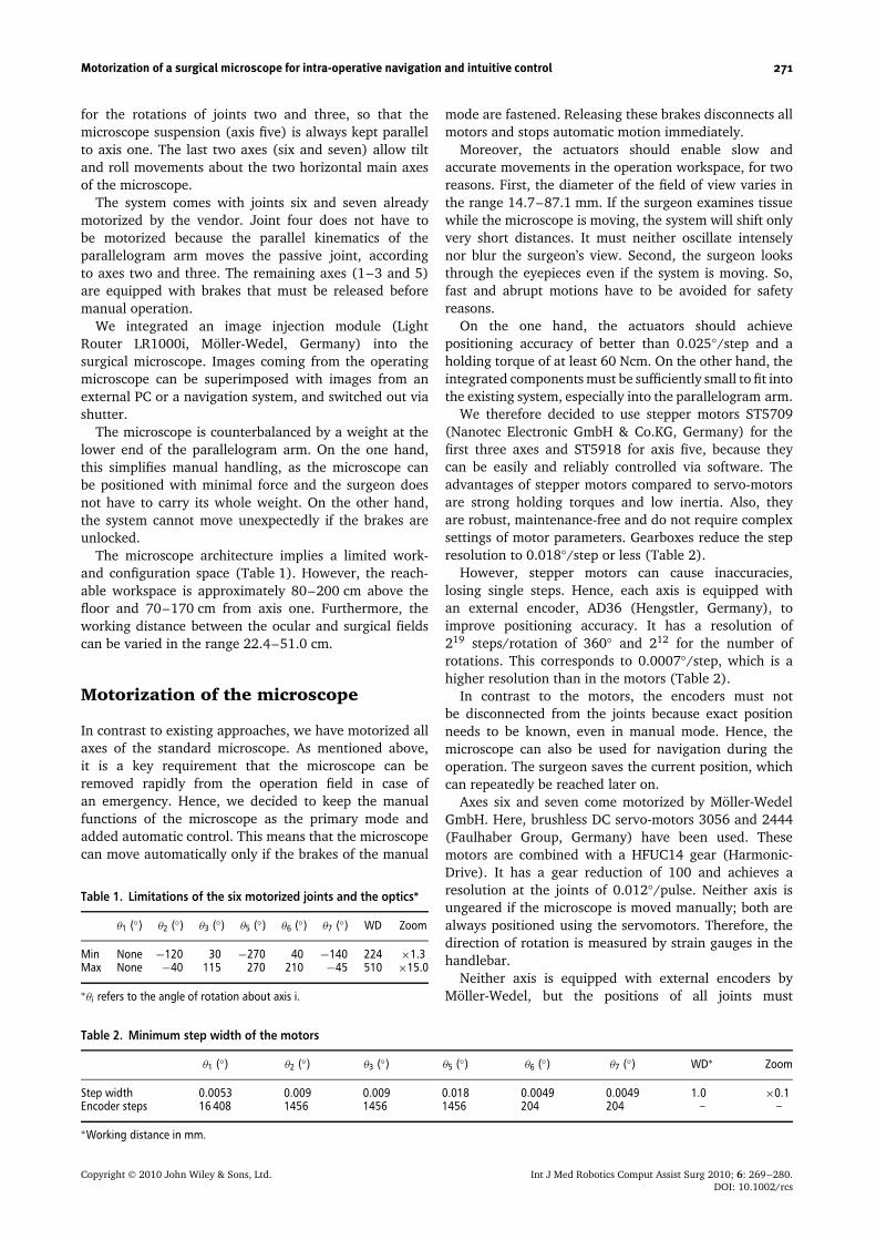
We developed two small remote controls that can befastened to one of the surgical instruments, e.g. theaspirator (Figure 2). The first one uses an accelerometerto determine the motion direction. The surgeon sets thedirection by tilting the remote control into the designateddirection relative to its initial position. A motion task (e.g.pivotation) is initialized by pressing a button, which isplaced at one side of the remote control. The movementstarts as soon as the button is released, so that the surgeoncan adjust the direction while keeping the button pressed.Its dimensions are 46.6 × 15.1 × 9 mm.
The second one consists of a small joystick. It can becontrolled by the index finger and provides a direction in2D. The motion task starts as soon as the joystick is pushedinto the designated direction and stops by releasing thejoystick. The dimensions are 31.2 × 17.4 × 21.9 mm.
The actual mode of control is displayed in one of theoculars of the microscope, e.g. indicating the directionof the next motion. Hence, the surgeon does not have toavert his eyes from the field of operation while positioningthe microscope.
In addition to motion tasks such as translation orpivotation, the surgeon can also control a navigationtask using the remote control. Herewith, the surgeon canchoose a target point from a list of defined positions, e.g.previously examined tissue points. This enables fast andreliable repositioning of the microscope without affectingthe surgeon’s workflow.
The remote control also contains a Bluetooth moduleto provide wireless communication with the external PC.The module guarantees high security of the sent data.Encryption and authentication improve data integrity, sothat it can be used dependably for medical devices.
An external PC receives all tasks from either theremote control or a graphical user interface (GUI).It executes the main calculations, which require huge
Figure 2. A small remote control can easily be attached to one of the surgical instruments, e.g. the aspirator. It determines themotion direction, using either an accelerometer (right) or a joystick (left)
Copyright 2010 John Wiley & Sons, Ltd. Int J Med Robotics Comput Assist Surg 2010; 6: 269–280.DOI: 10.1002/rcs
Motorization of a surgical microscope for intra-operative navigation and intuitive control 273
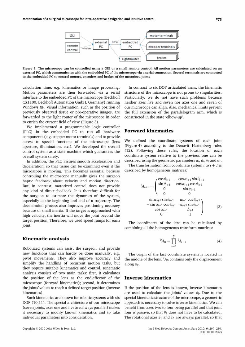
Figure 3. The microscope can be controlled using a GUI or a small remote control. All motion parameters are calculated on anexternal PC, which communicates with the embedded PC of the microscope via a serial connection. Several terminals are connectedto the embedded PC to control motors, encoders and brakes of the motorized joints
calculation time, e.g. kinematics or image processing.Motion parameters are then forwarded via a serialinterface to the embedded PC of the microscope (BeckhoffCX1100, Beckhoff Automation GmbH, Germany) runningWindows XP. Visual information, such as the position ofpreviously observed tissue or pre-operative images, areforwarded to the light router of the microscope in orderto enrich the current field of view (Figure 3).
We implemented a programmable logic controller(PLC) in the embedded PC to run all hardwarecomponents (e.g. stepper motor terminals) and to provideaccess to special functions of the microscope (lensaperture, illumination, etc.). We developed the overallcontrol system as a state machine which guarantees theoverall system safety.
In addition, the PLC assures smooth acceleration anddeceleration, so that tissue can be examined even if themicroscope is moving. This becomes essential becausecontrolling the microscope manually gives the surgeonhaptic feedback about velocity and motion direction.But, in contrast, motorized control does not provideany kind of direct feedback. It is therefore difficult forthe surgeon to estimate the dynamics of the system,especially at the beginning and end of a trajectory. Thedeceleration process also improves positioning accuracybecause of small inertia. If the target is approached withhigh velocity, the inertia will move the joint beyond thetarget position. Therefore, we used speed ramps for eachjoint.
Kinematic analysis
Robotized systems can assist the surgeon and providenew functions that can hardly be done manually, e.g.pivot movements. They also improve accuracy andsimplify the handling of recurrent motion tasks, butthey require suitable kinematics and control. Kinematicanalysis consists of two main tasks: first, it calculatesthe position of the lens as the end-effector of themicroscope (forward kinematics); second, it determinesthe joints’ values to reach a defined target position (inversekinematics).
Such kinematics are known for robotic systems with sixDOF (10,11). The special architecture of our microscope(seven joints, axes one and five are always parallel) makesit necessary to modify known kinematics and to takeindividual parameters into consideration.
In contrast to six DOF articulated arms, the kinematicstructure of the microscope is not prone to singularities.Particularly, we do not have such problems becauseneither axes five and seven nor axes one and seven ofour microscope can align. Also, mechanical limits preventthe full extension of the parallelogram arm, which isconstructed in the state ‘elbow-up’.
Forward kinematics
We defined the coordinate systems of each joint(Figure 4) according to the Denavit–Hartenberg rules(12). Following these rules, the location of eachcoordinate system relative to the previous one can bedescribed using the geometric parameters ai, di, θi and αi.
The transformation from coordinate system i to i + 1 isdescribed by homogeneous matrices:
iAi+1 =
cos θi+1 − cos αi+1 sin θi+1
sin θi+1 cos αi+1 cos θi+1
0 sin αi+1
0 0sin αi+1 sin θi+1 ai+1 cos θi+1
− sin αi+1 cos θi+1 ai+1 sin θi+1
cos αi+1 di+1
0 1
(3)
The coordinates of the lens can be calculated bycombining all the homogeneous transform matrices:
0A8 =7∏
i=0
iAi+1 (4)
The origin of the last coordinate system is located inthe middle of the lens. 7A8 contains only the displacementalong z7.
Inverse kinematics
If the position of the lens is known, inverse kinematicsare used to calculate the joints’ values θi. Due to thespecial kinematic structure of the microscope, a geometricapproach is necessary to solve inverse kinematics. We canbenefit from axes two to four being parallel and that jointfour is passive, so that θ4 does not have to be calculated.The rotational axes z1 and z5 are always parallel, so that
Copyright 2010 John Wiley & Sons, Ltd. Int J Med Robotics Comput Assist Surg 2010; 6: 269–280.DOI: 10.1002/rcs
274 M. Finke and A. Schweikard
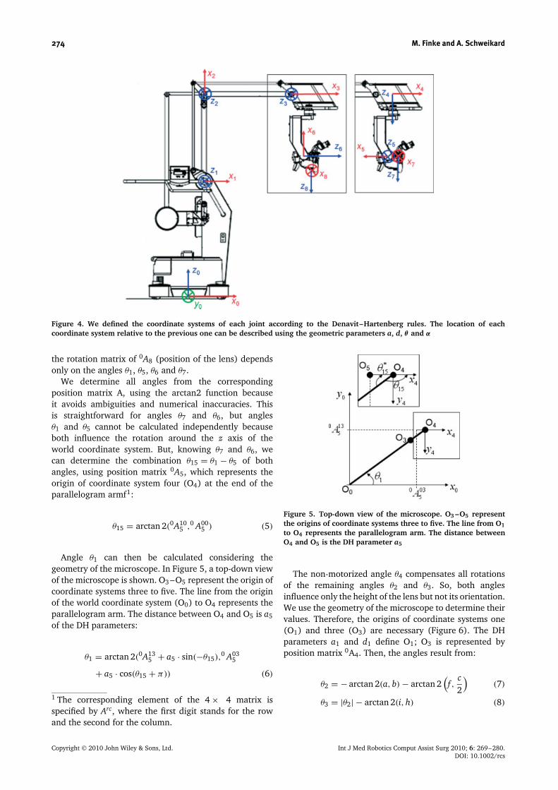
Figure 4. We defined the coordinate systems of each joint according to the Denavit–Hartenberg rules. The location of eachcoordinate system relative to the previous one can be described using the geometric parameters a, d, θ and α
the rotation matrix of 0A8 (position of the lens) dependsonly on the angles θ1, θ5, θ6 and θ7.
We determine all angles from the correspondingposition matrix A, using the arctan2 function becauseit avoids ambiguities and numerical inaccuracies. Thisis straightforward for angles θ7 and θ6, but anglesθ1 and θ5 cannot be calculated independently becauseboth influence the rotation around the z axis of theworld coordinate system. But, knowing θ7 and θ6, wecan determine the combination θ15 = θ1 − θ5 of bothangles, using position matrix 0A5, which represents theorigin of coordinate system four (O4) at the end of theparallelogram armf1:
θ15 = arctan 2(0A105 ,0 A00
5 ) (5)
Angle θ1 can then be calculated considering thegeometry of the microscope. In Figure 5, a top-down viewof the microscope is shown. O3 –O5 represent the origin ofcoordinate systems three to five. The line from the originof the world coordinate system (O0) to O4 represents theparallelogram arm. The distance between O4 and O5 is a5
of the DH parameters:
θ1 = arctan 2(0A135 + a5 · sin(−θ15),
0 A035
+ a5 · cos(θ15 + π)) (6)
1 The corresponding element of the 4 × 4 matrix isspecified by Arc, where the first digit stands for the rowand the second for the column.
Figure 5. Top-down view of the microscope. O3 –O5 representthe origins of coordinate systems three to five. The line from O1to O4 represents the parallelogram arm. The distance betweenO4 and O5 is the DH parameter a5
The non-motorized angle θ4 compensates all rotationsof the remaining angles θ2 and θ3. So, both anglesinfluence only the height of the lens but not its orientation.We use the geometry of the microscope to determine theirvalues. Therefore, the origins of coordinate systems one(O1) and three (O3) are necessary (Figure 6). The DHparameters a1 and d1 define O1; O3 is represented byposition matrix 0A4. Then, the angles result from:
θ2 = − arctan 2(a, b) − arctan 2(f ,
c2
)(7)
θ3 = |θ2| − arctan 2(i, h) (8)
Copyright 2010 John Wiley & Sons, Ltd. Int J Med Robotics Comput Assist Surg 2010; 6: 269–280.DOI: 10.1002/rcs

Motorization of a surgical microscope for intra-operative navigation and intuitive control 275
Figure 6. For inverse kinematics, a geometric approach must beused to calculate θ2 and θ3. The thick black lines (d, e) representthe parallelogram arm. O1 and O3 are the origins of coordinatesystems one and three
Applications
A substantial advantage of the fully motorized microscoperesults from the possibility of positioning the systembased on target points defined in a 3D model ofthe patient. We built this model using pre-operative
images (e.g. MRI). We implemented a procedure toregister the patient to the images using a standardalgorithm (13).
The surgeon chooses desired target points on thesurface of the 3D model and saves them in a targetlist (Figure 7). During surgery he selects a point fromthis list and the microscope automatically focuses thedesignated tissue. The joint positions to reach the targetare calculated using inverse kinematics.
Another advantage results from the exact knowledge ofall joints’ positions. Hence, for each examined target thecoordinates and the viewing direction can be calculatedusing forward kinematics. The surgeon can add intra-operatively focused positions to the target list in orderto re-examine them later. Also, the focal point inside thepatient can be displayed relative to the 3D model and thecorresponding slices of the pre-operative images can bepresented.
The microscope has seven rotational joints (Figure 1).This architecture makes Cartesian movements, i.e. parallel
Figure 7. The GUI on the left side shows the current field of view, where a knee model is focused. The arrow buttons can be usedto move the microscope. The surgeon chooses desired target points on the surface of the 3D model and saves them in a target list(right)
Copyright 2010 John Wiley & Sons, Ltd. Int J Med Robotics Comput Assist Surg 2010; 6: 269–280.DOI: 10.1002/rcs
276 M. Finke and A. Schweikard
shifts of the lens, in the x, y or z directions (translation)very difficult to perform manually. This task can easilybe done with the robotic microscope using inversekinematics. Starting from the current focal point pcurrand the viewing direction v, the new position is definedby:
pnew = pcurr + (x, y, z)T (9)
Then the inverse kinematics is solved for pnew with theviewing direction v and the calculated parameters areused to position the microscope.
Pivot movements around the current focal point areperformed in a similar way. For these movements, theworking distance and the focal point are maintained andonly the viewing direction is changed. This means thatat least three joints have to be moved, but more oftenchanges of all joints are necessary. These movementscan hardly be done manually or they are at least verytime-consuming. The surgeon has to compensate theinertia of the microscope and the current image planewill most likely be left, simply because he easily movesthe microscope too far in one direction. Our roboticmicroscope facilitates such movements. Therefore, theinverse kinematics are solved for pcurr and vnew, which iscalculated by rotating vcurr around arbitrary angles α, β
and χ .Exact translations and pivotations are fundamental
for automatic scans of tissue using optical coherencetomography (OCT) (14). The combination of a non-motorized microscope and OCT has been described in(15), where the surgeon has to position the probemanually. By contrast, we can automatically adjust theprobe perpendicular to the surface and scan large areasby shifting the lens parallel to the tissue. We calculate thetarget position for each scan using inverse kinematics ofthe robotic microscope.
The surgeon can choose additional, visual information,which superimposes the current field of view. Thatinvolves information about intra- as well as pre-operatively determined target positions, e.g. the locationof a tumour covered by healthy tissue. Hence, the surgeondoes not have to avert his eyes from the field of operationin order to use preoperative images for navigation tasks.
All automatic movements must be initialized by thesurgeon. Basic functions, e.g. translation or pivotation,can be controlled using the small remote control placedat the surgical instrument.
As we have defined above, movements of themicroscope can be divided into two categories. On theone hand, the surgeon uses manual mode to positionthe microscope quickly but imprecisely, e.g. for initialpositioning. On the other hand, robotized movements areused for slow but exact repositioning while the surgeonexamines tissue, e.g. during tumour resection. That iswhy we decided to maintain the manual handling of themicroscope and added motorization just for movementsof the second category.
The microscope is still usable manually in the sameway as before. We compensated the weights of the
parallelogram arm, so that the microscope will holdits position even if the brakes are unlocked. This willalso disconnect all motors so that automatic movementsare stopped immediately. If the microscope movesautomatically, a collision will be avoided just by movingit aside manually.
The velocity for robotized movements can be variedfrom 0.25◦/s to 4.0◦/s. Velocity and workspace are limiteddue to safety reasons. This enables the observation ofenlarged tissue while the microscope is moving andpossible collision can be detected in time. This isacceptable if the visible area is shifted only slightly.Otherwise, the manual mode has to be used.
System safety
Safety is a challenging requirement for automaticpositioning, because the patient must be placed in theworkspace of the microscope and the medical staff mustfrequently interact with the system. We distinguishedsoftware and hardware methods to guarantee their safety.In this context, it is advantageous that the microscopeworks non-invasively and has a working distance of atleast 22.4 cm.
The hardware of the microscope provides safety bythe following characteristics. First, the parallelogramarm is counterbalanced, so that the microscope will notmove even if the brakes are released. Second, everyactive movement is stopped by initiating the manualmode, because this disconnects joint arms and motorsimmediately. Third, an unexpected power failure doesnot lock the joints. So, the microscope can be removedfrom the operation table at any time.
Even if it is practically difficult for software reliabilityto be 100%, several features to improve the overall safetyof the system exist. First, prior to each movement it istested whether the designated target point is reachable.Second, the distance covered by each joint is limited forevery movement (e.g. 10◦). Third, the system stops allmovements if a communication timeout occurs. Fourth,we limited the velocity of the microscope to avoid abruptmovements. This protects the surgeon who observes tissuewhile the microscope is moving.
The combination of software and hardware methods isa good solution for achieving a safe system.
Results
We carried out laboratory experiments to examine thepositioning accuracy of the microscope for absoluteand relative movements as well as its repeatability.The accuracy error describes the ability to position thefocus point of the microscope at a desired target point.Repeatability describes the ability of the microscope toreturn to the same position. While accuracy is defined withrespect to absolute coordinates, the repeatability describes
Copyright 2010 John Wiley & Sons, Ltd. Int J Med Robotics Comput Assist Surg 2010; 6: 269–280.DOI: 10.1002/rcs
Motorization of a surgical microscope for intra-operative navigation and intuitive control 277
the spatial deviation from the average of displacements(16).
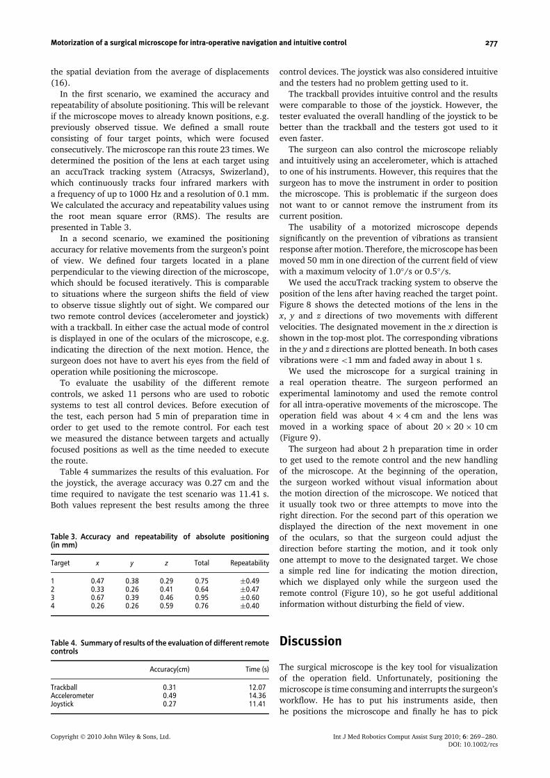
In the first scenario, we examined the accuracy andrepeatability of absolute positioning. This will be relevantif the microscope moves to already known positions, e.g.previously observed tissue. We defined a small routeconsisting of four target points, which were focusedconsecutively. The microscope ran this route 23 times. Wedetermined the position of the lens at each target usingan accuTrack tracking system (Atracsys, Swizerland),which continuously tracks four infrared markers witha frequency of up to 1000 Hz and a resolution of 0.1 mm.We calculated the accuracy and repeatability values usingthe root mean square error (RMS). The results arepresented in Table 3.
In a second scenario, we examined the positioningaccuracy for relative movements from the surgeon’s pointof view. We defined four targets located in a planeperpendicular to the viewing direction of the microscope,which should be focused iteratively. This is comparableto situations where the surgeon shifts the field of viewto observe tissue slightly out of sight. We compared ourtwo remote control devices (accelerometer and joystick)with a trackball. In either case the actual mode of controlis displayed in one of the oculars of the microscope, e.g.indicating the direction of the next motion. Hence, thesurgeon does not have to avert his eyes from the field ofoperation while positioning the microscope.
To evaluate the usability of the different remotecontrols, we asked 11 persons who are used to roboticsystems to test all control devices. Before execution ofthe test, each person had 5 min of preparation time inorder to get used to the remote control. For each testwe measured the distance between targets and actuallyfocused positions as well as the time needed to executethe route.
Table 4 summarizes the results of this evaluation. Forthe joystick, the average accuracy was 0.27 cm and thetime required to navigate the test scenario was 11.41 s.Both values represent the best results among the three
Table 3. Accuracy and repeatability of absolute positioning(in mm)
Target x y z Total Repeatability
1 0.47 0.38 0.29 0.75 ±0.492 0.33 0.26 0.41 0.64 ±0.473 0.67 0.39 0.46 0.95 ±0.604 0.26 0.26 0.59 0.76 ±0.40
Table 4. Summary of results of the evaluation of different remotecontrols
Accuracy(cm) Time (s)
Trackball 0.31 12.07Accelerometer 0.49 14.36Joystick 0.27 11.41
control devices. The joystick was also considered intuitiveand the testers had no problem getting used to it.
The trackball provides intuitive control and the resultswere comparable to those of the joystick. However, thetester evaluated the overall handling of the joystick to bebetter than the trackball and the testers got used to iteven faster.
The surgeon can also control the microscope reliablyand intuitively using an accelerometer, which is attachedto one of his instruments. However, this requires that thesurgeon has to move the instrument in order to positionthe microscope. This is problematic if the surgeon doesnot want to or cannot remove the instrument from itscurrent position.
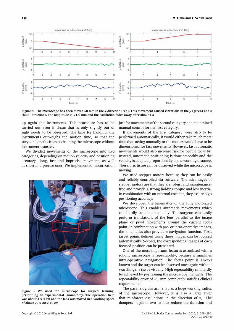
The usability of a motorized microscope dependssignificantly on the prevention of vibrations as transientresponse after motion. Therefore, the microscope has beenmoved 50 mm in one direction of the current field of viewwith a maximum velocity of 1.0◦/s or 0.5◦/s.
We used the accuTrack tracking system to observe theposition of the lens after having reached the target point.Figure 8 shows the detected motions of the lens in thex, y and z directions of two movements with differentvelocities. The designated movement in the x direction isshown in the top-most plot. The corresponding vibrationsin the y and z directions are plotted beneath. In both casesvibrations were <1 mm and faded away in about 1 s.
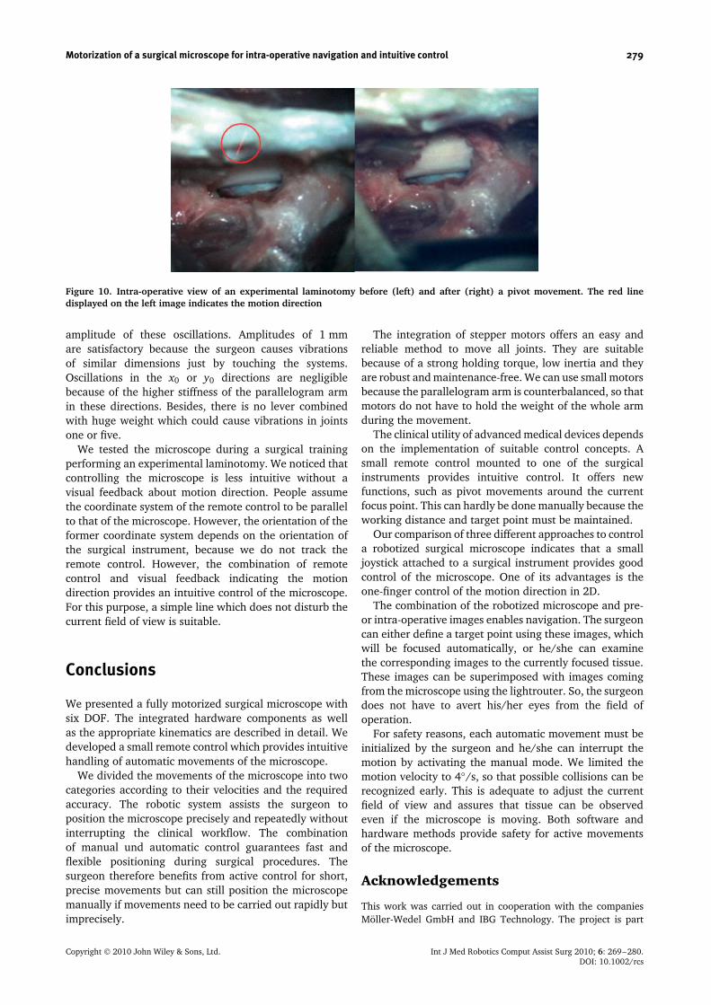
We used the microscope for a surgical training ina real operation theatre. The surgeon performed anexperimental laminotomy and used the remote controlfor all intra-operative movements of the microscope. Theoperation field was about 4 × 4 cm and the lens wasmoved in a working space of about 20 × 20 × 10 cm(Figure 9).
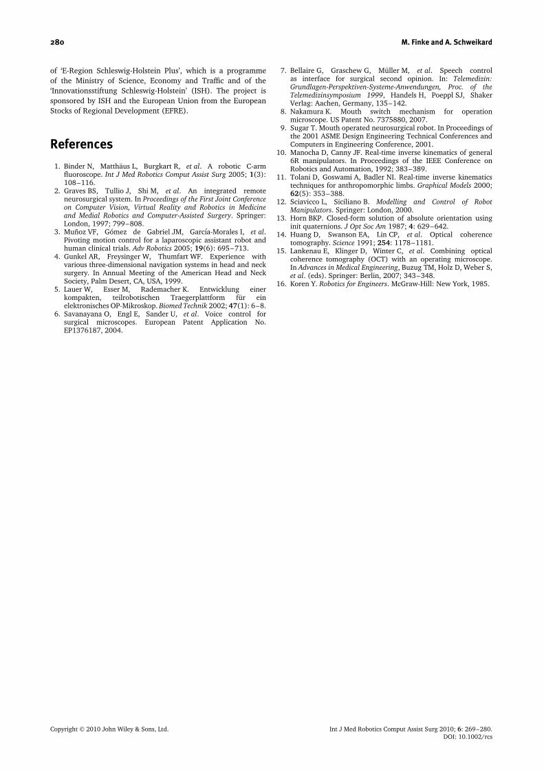
The surgeon had about 2 h preparation time in orderto get used to the remote control and the new handlingof the microscope. At the beginning of the operation,the surgeon worked without visual information aboutthe motion direction of the microscope. We noticed thatit usually took two or three attempts to move into theright direction. For the second part of this operation wedisplayed the direction of the next movement in oneof the oculars, so that the surgeon could adjust thedirection before starting the motion, and it took onlyone attempt to move to the designated target. We chosea simple red line for indicating the motion direction,which we displayed only while the surgeon used theremote control (Figure 10), so he got useful additionalinformation without disturbing the field of view.
Discussion
The surgical microscope is the key tool for visualizationof the operation field. Unfortunately, positioning themicroscope is time consuming and interrupts the surgeon’sworkflow. He has to put his instruments aside, thenhe positions the microscope and finally he has to pick
Copyright 2010 John Wiley & Sons, Ltd. Int J Med Robotics Comput Assist Surg 2010; 6: 269–280.DOI: 10.1002/rcs
278 M. Finke and A. Schweikard
Figure 8. The microscope has been moved 50 mm in the x-direction (red). This movement caused vibrations in the y (green) and z(blue) directions. The amplitude is <1.0 mm and the oscillation fades away after about 1 s
up again the instruments. This procedure has to becarried out even if tissue that is only slightly out ofsight needs to be observed. The time for handling theinstruments outweighs the motion time, so that thesurgeon benefits from positioning the microscope withoutinstrument transfer.
We divided movements of the microscope into twocategories, depending on motion velocity and positioningaccuracy – long, fast and imprecise movments as wellas short and precise ones. We implemented motorization
Figure 9. We used the microscope for surgical training,performing an experimental laminotomy. The operation fieldwas about 4 × 4 cm and the lens was moved in a working spaceof about 20 × 20 × 10 cm
just for movements of the second category and maintainedmanual control for the first category.
If movements of the first category were also to beperformed automatically, it would either take much moretime than acting manually or the motors would have to bedimensioned for fast movements.However, fast automaticmovements would also increase risk for people close by.Instead, automatic positioning is done smoothly and thevelocity is adapted proportionally to the working distance.Therefore, tissue can be observed while the microscope ismoving.
We used stepper motors because they can be easilyand reliably controlled via software. The advantages ofstepper motors are that they are robust and maintenance-free and provide a strong holding torque and low inertia.In combination with an external encoder, they assure highpositioning accuracy.
We developed the kinematics of the fully motorizedmicroscope. This enables automatic movements whichcan hardly be done manually. The surgeon can easilyperform translations of the lens parallel to the imageplane or pivot movements around the current focuspoint. In combination with pre- or intra-operative images,the kinematics also provide a navigation function. First,target points defined using these images can be focusedautomatically. Second, the corresponding images of eachfocused position can be presented.
One of the most important features associated with arobotic microscope is repeatability, because it simplifiesintra-operative navigation. The focus point is alwaysknown and the target can be observed once again withoutsearching the tissue visually. High repeatability can hardlybe achieved by positioning the microscope manually. Therepeatability error of <1 mm completely satisfies clinicalrequirements.
The parallelogram arm enables a huge working radiusof the microscope. However, it is also a large leverthat reinforces oscillations in the direction of z0. Thedampers in joints two to four reduce the duration and
Copyright 2010 John Wiley & Sons, Ltd. Int J Med Robotics Comput Assist Surg 2010; 6: 269–280.DOI: 10.1002/rcs
Motorization of a surgical microscope for intra-operative navigation and intuitive control 279
Figure 10. Intra-operative view of an experimental laminotomy before (left) and after (right) a pivot movement. The red linedisplayed on the left image indicates the motion direction
amplitude of these oscillations. Amplitudes of 1 mmare satisfactory because the surgeon causes vibrationsof similar dimensions just by touching the systems.Oscillations in the x0 or y0 directions are negligiblebecause of the higher stiffness of the parallelogram armin these directions. Besides, there is no lever combinedwith huge weight which could cause vibrations in jointsone or five.
We tested the microscope during a surgical trainingperforming an experimental laminotomy. We noticed thatcontrolling the microscope is less intuitive without avisual feedback about motion direction. People assumethe coordinate system of the remote control to be parallelto that of the microscope. However, the orientation of theformer coordinate system depends on the orientation ofthe surgical instrument, because we do not track theremote control. However, the combination of remotecontrol and visual feedback indicating the motiondirection provides an intuitive control of the microscope.For this purpose, a simple line which does not disturb thecurrent field of view is suitable.
Conclusions
We presented a fully motorized surgical microscope withsix DOF. The integrated hardware components as wellas the appropriate kinematics are described in detail. Wedeveloped a small remote control which provides intuitivehandling of automatic movements of the microscope.
We divided the movements of the microscope into twocategories according to their velocities and the requiredaccuracy. The robotic system assists the surgeon toposition the microscope precisely and repeatedly withoutinterrupting the clinical workflow. The combinationof manual und automatic control guarantees fast andflexible positioning during surgical procedures. Thesurgeon therefore benefits from active control for short,precise movements but can still position the microscopemanually if movements need to be carried out rapidly butimprecisely.
The integration of stepper motors offers an easy andreliable method to move all joints. They are suitablebecause of a strong holding torque, low inertia and theyare robust and maintenance-free. We can use small motorsbecause the parallelogram arm is counterbalanced, so thatmotors do not have to hold the weight of the whole armduring the movement.
The clinical utility of advanced medical devices dependson the implementation of suitable control concepts. Asmall remote control mounted to one of the surgicalinstruments provides intuitive control. It offers newfunctions, such as pivot movements around the currentfocus point. This can hardly be done manually because theworking distance and target point must be maintained.
Our comparison of three different approaches to controla robotized surgical microscope indicates that a smalljoystick attached to a surgical instrument provides goodcontrol of the microscope. One of its advantages is theone-finger control of the motion direction in 2D.
The combination of the robotized microscope and pre-or intra-operative images enables navigation. The surgeoncan either define a target point using these images, whichwill be focused automatically, or he/she can examinethe corresponding images to the currently focused tissue.These images can be superimposed with images comingfrom the microscope using the lightrouter. So, the surgeondoes not have to avert his/her eyes from the field ofoperation.
For safety reasons, each automatic movement must beinitialized by the surgeon and he/she can interrupt themotion by activating the manual mode. We limited themotion velocity to 4◦/s, so that possible collisions can berecognized early. This is adequate to adjust the currentfield of view and assures that tissue can be observedeven if the microscope is moving. Both software andhardware methods provide safety for active movementsof the microscope.
Acknowledgements
This work was carried out in cooperation with the companiesMoller-Wedel GmbH and IBG Technology. The project is part
Copyright 2010 John Wiley & Sons, Ltd. Int J Med Robotics Comput Assist Surg 2010; 6: 269–280.DOI: 10.1002/rcs
280 M. Finke and A. Schweikard
of ‘E-Region Schleswig-Holstein Plus’, which is a programmeof the Ministry of Science, Economy and Traffic and of the‘Innovationsstiftung Schleswig-Holstein’ (ISH). The project issponsored by ISH and the European Union from the EuropeanStocks of Regional Development (EFRE).
References
1. Binder N, Matthaus L, Burgkart R, et al. A robotic C-armfluoroscope. Int J Med Robotics Comput Assist Surg 2005; 1(3):108–116.
2. Graves BS, Tullio J, Shi M, et al. An integrated remoteneurosurgical system. In Proceedings of the First Joint Conferenceon Computer Vision, Virtual Reality and Robotics in Medicineand Medial Robotics and Computer-Assisted Surgery. Springer:London, 1997; 799–808.
3. Munoz VF, Gomez de Gabriel JM, Garcıa-Morales I, et al.Pivoting motion control for a laparoscopic assistant robot andhuman clinical trials. Adv Robotics 2005; 19(6): 695–713.
4. Gunkel AR, Freysinger W, Thumfart WF. Experience withvarious three-dimensional navigation systems in head and necksurgery. In Annual Meeting of the American Head and NeckSociety, Palm Desert, CA, USA, 1999.
5. Lauer W, Esser M, Rademacher K. Entwicklung einerkompakten, teilrobotischen Traegerplattform fur einelektronisches OP-Mikroskop. Biomed Technik 2002; 47(1): 6–8.
6. Savanayana O, Engl E, Sander U, et al. Voice control forsurgical microscopes. European Patent Application No.EP1376187, 2004.
7. Bellaire G, Graschew G, Muller M, et al. Speech controlas interface for surgical second opinion. In: Telemedizin:Grundlagen-Perspektiven-Systeme-Anwendungen, Proc. of theTelemedizinsymposium 1999, Handels H, Poeppl SJ, ShakerVerlag: Aachen, Germany, 135–142.
8. Nakamura K. Mouth switch mechanism for operationmicroscope. US Patent No. 7375880, 2007.
9. Sugar T. Mouth operated neurosurgical robot. In Proceedings ofthe 2001 ASME Design Engineering Technical Conferences andComputers in Engineering Conference, 2001.
10. Manocha D, Canny JF. Real-time inverse kinematics of general6R manipulators. In Proceedings of the IEEE Conference onRobotics and Automation, 1992; 383–389.
11. Tolani D, Goswami A, Badler NI. Real-time inverse kinematicstechniques for anthropomorphic limbs. Graphical Models 2000;62(5): 353–388.
12. Sciavicco L, Siciliano B. Modelling and Control of RobotManipulators. Springer: London, 2000.
13. Horn BKP. Closed-form solution of absolute orientation usinginit quaternions. J Opt Soc Am 1987; 4: 629–642.
14. Huang D, Swanson EA, Lin CP, et al. Optical coherencetomography. Science 1991; 254: 1178–1181.
15. Lankenau E, Klinger D, Winter C, et al. Combining opticalcoherence tomography (OCT) with an operating microscope.In Advances in Medical Engineering, Buzug TM, Holz D, Weber S,et al. (eds). Springer: Berlin, 2007; 343–348.
16. Koren Y. Robotics for Engineers. McGraw-Hill: New York, 1985.
Copyright 2010 John Wiley & Sons, Ltd. Int J Med Robotics Comput Assist Surg 2010; 6: 269–280.DOI: 10.1002/rcs