motorcycle service manual - encontrapeca zx 6r.pdf · foreword this manual is designed primarily...
TRANSCRIPT

Ninja ZX-6R
MotorcycleService Manual


This quick reference guide will assistyou in locating a desired topic or pro-cedure.•Bend the pages back to match theblack tab of the desired chapter num-ber with the black tab on the edge ateach table of contents page.
•Refer to the sectional table of contentsfor the exact pages to locate the spe-cific topic required.
Quick Reference Guide
General Information 1 j
Periodic Maintenance 2 j
Fuel System (DFI) 3 j
Cooling System 4 j
Engine Top End 5 j
Clutch 6 j
Engine Lubrication System 7 j
Engine Removal/Installation 8 j
Crankshaft/Transmission 9 j
Wheels/Tires 10 j
Final Drive 11 j
Brakes 12 j
Suspension 13 j
Steering 14 j
Frame 15 j
Electrical System 16 j
Appendix 17 j

Ninja ZX-6R
MotorcycleService Manual
All rights reserved. No parts of this publication may be reproduced, stored in a retrieval system, ortransmitted in any form or by any means, electronic mechanical photocopying, recording or otherwise,without the prior written permission of Quality Assurance Department/Consumer Products & MachineryCompany/Kawasaki Heavy Industries, Ltd., Japan.
No liability can be accepted for any inaccuracies or omissions in this publication, although every possiblecare has been taken to make it as complete and accurate as possible.
The right is reserved to make changes at any time without prior notice and without incurring an obligationto make such changes to products manufactured previously. See your Motorcycle dealer for the latestinformation on product improvements incorporated after this publication.
All information contained in this publication is based on the latest product information available at the timeof publication. Illustrations and photographs in this publication are intended for reference use only and maynot depict actual model component parts.
© 2004 Kawasaki Heavy Industries, Ltd. First Edition (1): Sep. 30, 2004 (M)
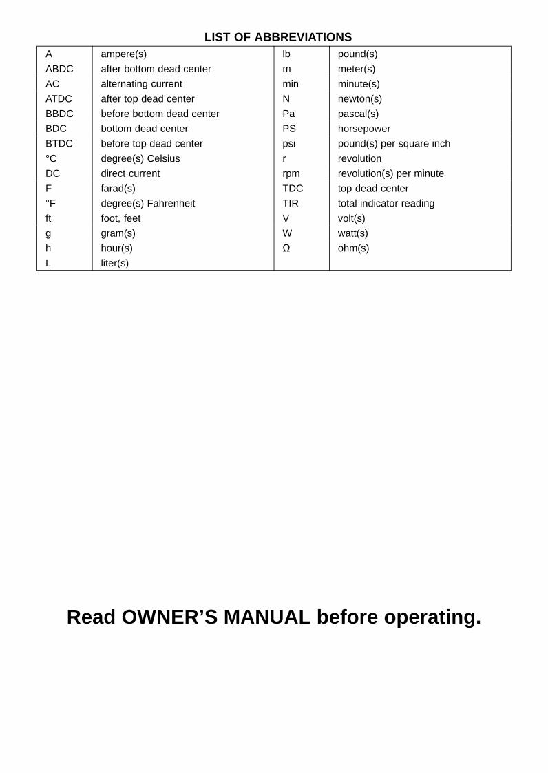
LIST OF ABBREVIATIONSA ampere(s) lb pound(s)
ABDC after bottom dead center m meter(s)
AC alternating current min minute(s)
ATDC after top dead center N newton(s)
BBDC before bottom dead center Pa pascal(s)
BDC bottom dead center PS horsepower
BTDC before top dead center psi pound(s) per square inch
°C degree(s) Celsius r revolution
DC direct current rpm revolution(s) per minute
F farad(s) TDC top dead center
°F degree(s) Fahrenheit TIR total indicator reading
ft foot, feet V volt(s)
g gram(s) W watt(s)
h hour(s) Ω ohm(s)
L liter(s)
Read OWNER’S MANUAL before operating.

EMISSION CONTROL INFORMATION
To protect the environment in which we all live, Kawasaki has incorporated crankcase emis-sion (1) and exhaust emission (2) control systems in compliance with applicable regulations ofthe United States Environmental Protection Agency and California Air Resources Board. Addi-tionally, Kawasaki has incorporated an evaporative emission control system (3) in compliancewith applicable regulations of the California Air Resources Board on vehicles sold in Californiaonly.1. Crankcase Emission Control SystemThis system eliminates the release of crankcase vapors into the atmosphere. Instead, the vapors
are routed through an oil separator to the inlet side of the engine. While the engine is operating,the vapors are drawn into combustion chamber, where they are burned along with the fuel and airsupplied by the fuel injection system.
2. Exhaust Emission Control SystemThis system reduces the amount of pollutants discharged into the atmosphere by the exhaust
of this motorcycle. The fuel, ignition, and exhaust systems of this motorcycle have been carefullydesigned and constructed to ensure an efficient engine with low exhaust pollutant levels.
The exhaust system of this model motorcycle manufactured primarily for sale in California in-cludes a catalytic converter system.
3. Evaporative Emission Control SystemVapors caused by fuel evaporation in the fuel system are not vented into the atmosphere. In-
stead, fuel vapors are routed into the running engine to be burned, or stored in a canister whenthe engine is stopped. Liquid fuel is caught by a vapor separator and returned to the fuel tank.
The Clean Air Act, which is the Federal law covering motor vehicle pollution, contains what iscommonly referred to as the Act’s “tampering provisions”.
“Sec. 203(a) The following acts and the causing thereof are prohibited...(3)(A) for any person to remove or render inoperative any device or element of design installed
on or in a motor vehicle or motor vehicle engine in compliance with regulations under thistitle prior to its sale and delivery to the ultimate purchaser, or for any manufacturer or dealerknowingly to remove or render inoperative any such device or element of design after suchsale and delivery to the ultimate purchaser.
(3)(B) for any person engaged in the business of repairing, servicing, selling, leasing, or tradingmotor vehicles or motor vehicle engines, or who operates a fleet of motor vehicles know-ingly to remove or render inoperative any device or element of design installed on or in amotor vehicle or motor vehicle engine in compliance with regulations under this title follow-ing its sale and delivery to the ultimate purchaser...”
NOTEThe phrase “remove or render inoperative any device or element of design” has been generally
interpreted as follows.1. Tampering does not include the temporary removal or rendering inoperative of de-
vices or elements of design in order to perform maintenance.2. Tampering could include.
a.Maladjustment of vehicle components such that the emission standards are ex-ceeded.
b.Use of replacement parts or accessories which adversely affect the performanceor durability of the motorcycle.
c.Addition of components or accessories that result in the vehicle exceeding the stan-dards.
d.Permanently removing, disconnecting, or rendering inoperative any component orelement of design of the emission control systems.
WE RECOMMEND THAT ALL DEALERS OBSERVE THESE PROVISIONS OF FEDERAL LAW,THE VIOLATION OF WHICH IS PUNISHABLE BY CIVIL PENALTIES NOT EXCEEDING $10000 PER VIOLATION.

TAMPERING WITH NOISE CONTROL SYSTEM PROHIBITED
Federal law prohibits the following acts or the causing thereof. (1) The removal or renderinginoperative by any person other than for purposes of maintenance, repair, or replacement, of anydevice or element of design incorporated into any new vehicle for the purpose of noise controlprior to its sale or delivery to the ultimate purchaser or while it is in use, or (2) the use of thevehicle after such device or element of design has been removed or rendered inoperative byany person.
Among those acts presumed to constitute tampering are the acts listed below.
•Replacement of the original exhaust system or muffler with a component not in compliancewith Federal regulations.
• Removal of the muffler(s) or any internal portion of the muffler(s).
• Removal of the air box or air box cover.
•Modifications to the muffler(s) or air inlet system by cutting, drilling, or other means if suchmodifications result in increased noise levels.

Foreword
This manual is designed primarily for use bytrained mechanics in a properly equipped shop.However, it contains enough detail and basic in-formation to make it useful to the owner who de-sires to perform his own basic maintenance andrepair work. A basic knowledge of mechanics,the proper use of tools, and workshop proce-dures must be understood in order to carry outmaintenance and repair satisfactorily. When-ever the owner has insufficient experience ordoubts his ability to do the work, all adjust-ments, maintenance, and repair should be car-ried out only by qualified mechanics.
In order to perform the work efficiently andto avoid costly mistakes, read the text, thor-oughly familiarize yourself with the proceduresbefore starting work, and then do the work care-fully in a clean area. Whenever special tools orequipment are specified, do not use makeshifttools or equipment. Precision measurementscan only be made if the proper instruments areused, and the use of substitute tools may ad-versely affect safe operation.
For the duration of the warranty period,we recommend that all repairs and scheduledmaintenance be performed in accordance withthis service manual. Any owner maintenance orrepair procedure not performed in accordancewith this manual may void the warranty.
To get the longest life out of your vehicle.
• Follow the Periodic Maintenance Chart in theService Manual.
• Be alert for problems and non-scheduledmaintenance.
• Use proper tools and genuine Kawasaki Mo-torcycle parts. Special tools, gauges, andtesters that are necessary when servicingKawasaki motorcycles are introduced by theSpecial Tool Catalog or Manual. Genuineparts provided as spare parts are listed in theParts Catalog.
• Follow the procedures in this manual care-fully. Don’t take shortcuts.
• Remember to keep complete records of main-tenance and repair with dates and any newparts installed.
How to Use This ManualIn preparing this manual, we divided the prod-
uct into its major systems. These systems be-came the manual’s chapters. All informationfor a particular system from adjustment throughdisassembly and inspection is located in a sin-gle chapter.
The Quick Reference Guide shows you allof the product’s system and assists in locatingtheir chapters. Each chapter in turn has its owncomprehensive Table of Contents.
The Periodic Maintenance Chart is located inthe Periodic Maintenance chapter. The chartgives a time schedule for required maintenanceoperations.
If you want spark plug information, for exam-ple, go to the Periodic Maintenance Chart first.The chart tells you how frequently to clean andgap the plug. Next, use the Quick ReferenceGuide to locate the Periodic Maintenance chap-ter. Then, use the Table of Contents on the firstpage of the chapter to find the Spark Plug sec-tion.
Whenever you see these WARNING andCAUTION symbols, heed their instructions!Always follow safe operating and maintenancepractices.
WARNINGThis warning symbol identifies specialinstructions or procedures which, if notcorrectly followed, could result in per-sonal injury, or loss of life.
CAUTION
This caution symbol identifies specialinstructions or procedures which, if notstrictly observed, could result in dam-age to or destruction of equipment.
This manual contains four more symbols (inaddition to WARNING and CAUTION) which willhelp you distinguish different types of informa-tion.
NOTEThis note symbol indicates points of par-
ticular interest for more efficient and con-venient operation.
• Indicates a procedural step or work to bedone.Indicates a procedural sub-step or how to do
the work of the procedural step it follows. Italso precedes the text of a NOTE.Indicates a conditional step or what action totake based on the results of the test or inspec-tion in the procedural step or sub-step it fol-lows.In most chapters an exploded view illustration
of the system components follows the Table ofContents. In these illustrations you will find theinstructions indicating which parts require spec-ified tightening torque, oil, grease or a lockingagent during assembly.
GENERAL INFORMATION 1-1
1General Information
Table of Contents
Before Servicing ..................................................................................................................... 1-2Model Identification................................................................................................................. 1-7General Specifications............................................................................................................ 1-9Unit Conversion Table ............................................................................................................ 1-12

1-2 GENERAL INFORMATIONBefore Servicing
Before starting to perform an inspection service or carry out a disassembly and reassembly opera-tion on a motorcycle, read the precautions given below. To facilitate actual operations, notes, illustra-tions, photographs, cautions, and detailed descriptions have been included in each chapter wherevernecessary. This section explains the items that require particular attention during the removal andreinstallation or disassembly and reassembly of general parts.
Especially note the following.Battery Ground
Before completing any service on the motorcycle, discon-nect the battery cables from the battery to prevent the en-gine from accidentally turning over. Disconnect the groundcable (–) first and then the positive (+). When completedwith the service, first connect the positive (+) cable to thepositive (+) terminal of the battery then the negative (–) ca-ble to the negative terminal.
Edges of PartsLift large or heavy parts wearing gloves to prevent injury
from possible sharp edges on the parts.
SolventUse a high-flush point solvent when cleaning parts. High
-flush point solvent should be used according to directionsof the solvent manufacturer.
Cleaning vehicle before disassemblyClean the vehicle thoroughly before disassembly. Dirt or
other foreign materials entering into sealed areas during ve-hicle disassembly can cause excessive wear and decreaseperformance of the vehicle.

GENERAL INFORMATION 1-3Before Servicing
Arrangement and Cleaning of Removed PartsDisassembled parts are easy to confuse. Arrange the
parts according to the order the parts were disassembledand clean the parts in order prior to assembly.
Storage of Removed PartsAfter all the parts including subassembly parts have been
cleaned, store the parts in a clean area. Put a clean clothor plastic sheet over the parts to protect from any foreignmaterials that may collect before re-assembly.
InspectionReuse of worn or damaged parts may lead to serious ac-
cident. Visually inspect removed parts for corrosion, discol-oration, or other damage. Refer to the appropriate sectionsof this manual for service limits on individual parts. Replacethe parts if any damage has been found or if the part is be-yond its service limit.
Replacement PartsReplacement Parts must be KAWASAKI genuine or
recommended by KAWASAKI. Gaskets, O-rings, oil seals,grease seals, circlips or cotter pins must be replaced withnew ones whenever disassembled.
Assembly OrderIn most cases assembly order is the reverse of disassem-
bly, however, if assembly order is provided in this ServiceManual, follow the procedures given.
1-4 GENERAL INFORMATIONBefore Servicing
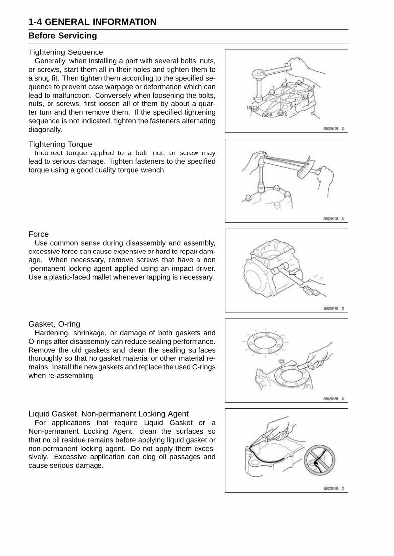
Tightening SequenceGenerally, when installing a part with several bolts, nuts,
or screws, start them all in their holes and tighten them toa snug fit. Then tighten them according to the specified se-quence to prevent case warpage or deformation which canlead to malfunction. Conversely when loosening the bolts,nuts, or screws, first loosen all of them by about a quar-ter turn and then remove them. If the specified tighteningsequence is not indicated, tighten the fasteners alternatingdiagonally.
Tightening TorqueIncorrect torque applied to a bolt, nut, or screw may
lead to serious damage. Tighten fasteners to the specifiedtorque using a good quality torque wrench.
ForceUse common sense during disassembly and assembly,
excessive force can cause expensive or hard to repair dam-age. When necessary, remove screws that have a non-permanent locking agent applied using an impact driver.Use a plastic-faced mallet whenever tapping is necessary.
Gasket, O-ringHardening, shrinkage, or damage of both gaskets and
O-rings after disassembly can reduce sealing performance.Remove the old gaskets and clean the sealing surfacesthoroughly so that no gasket material or other material re-mains. Install the new gaskets and replace the used O-ringswhen re-assembling
Liquid Gasket, Non-permanent Locking AgentFor applications that require Liquid Gasket or a
Non-permanent Locking Agent, clean the surfaces sothat no oil residue remains before applying liquid gasket ornon-permanent locking agent. Do not apply them exces-sively. Excessive application can clog oil passages andcause serious damage.
GENERAL INFORMATION 1-5Before Servicing
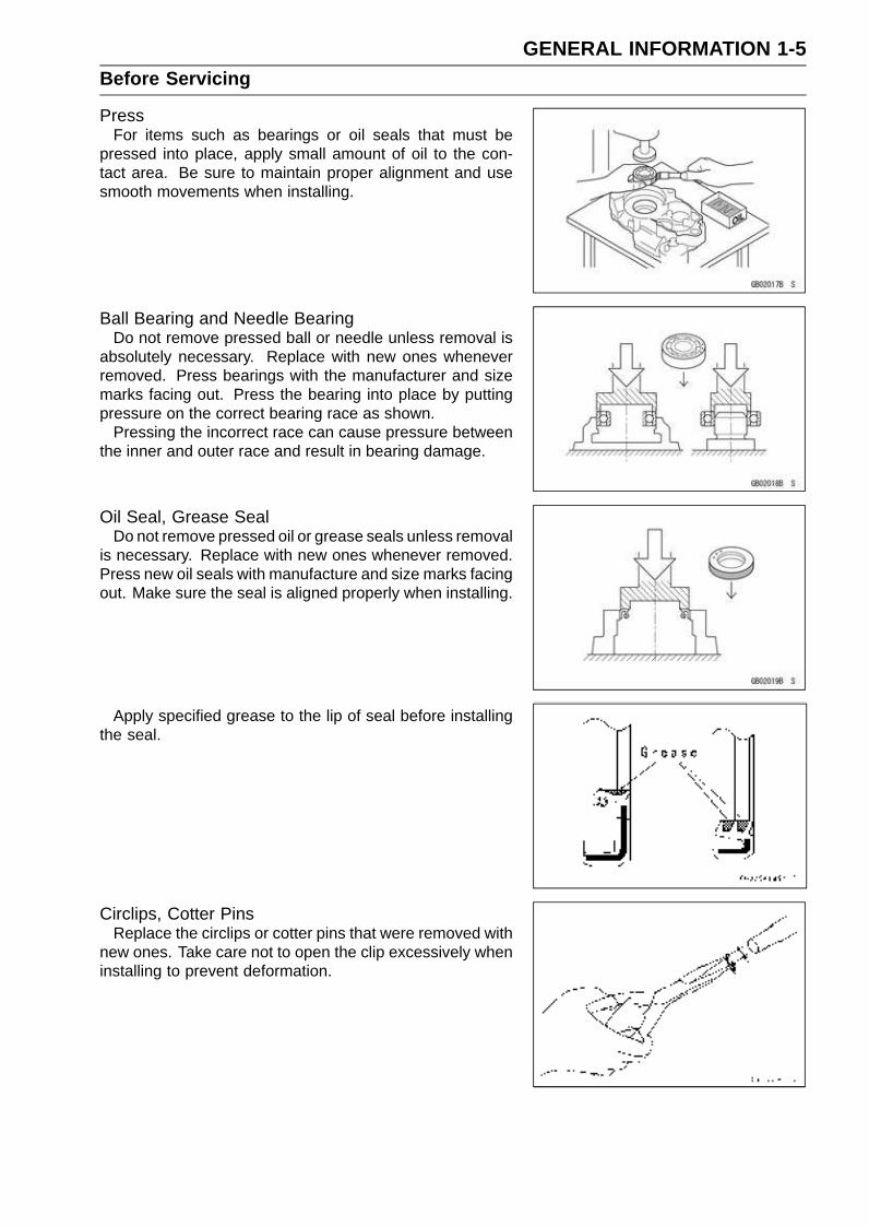
PressFor items such as bearings or oil seals that must be
pressed into place, apply small amount of oil to the con-tact area. Be sure to maintain proper alignment and usesmooth movements when installing.
Ball Bearing and Needle BearingDo not remove pressed ball or needle unless removal is
absolutely necessary. Replace with new ones wheneverremoved. Press bearings with the manufacturer and sizemarks facing out. Press the bearing into place by puttingpressure on the correct bearing race as shown.
Pressing the incorrect race can cause pressure betweenthe inner and outer race and result in bearing damage.
Oil Seal, Grease SealDo not remove pressed oil or grease seals unless removal
is necessary. Replace with new ones whenever removed.Press new oil seals with manufacture and size marks facingout. Make sure the seal is aligned properly when installing.
Apply specified grease to the lip of seal before installingthe seal.
Circlips, Cotter PinsReplace the circlips or cotter pins that were removed with
new ones. Take care not to open the clip excessively wheninstalling to prevent deformation.

1-6 GENERAL INFORMATIONBefore Servicing
LubricationIt is important to lubricate rotating or sliding parts during
assembly to minimize wear during initial operation. Lubri-cation points are called out throughout this manual, applythe specific oil or grease as specified.
Direction of Engine RotationWhen rotating the crankshaft by hand, the free play
amount of rotating direction will affect the adjustment. Ro-tate the crankshaft to positive direction (clockwise viewedfrom output side).
Electrical WiresA two-color wire is identified first by the primary color and
then the stripe color. Unless instructed otherwise, electricalwires must be connected to those of the same color.
GENERAL INFORMATION 1-7Model Identification
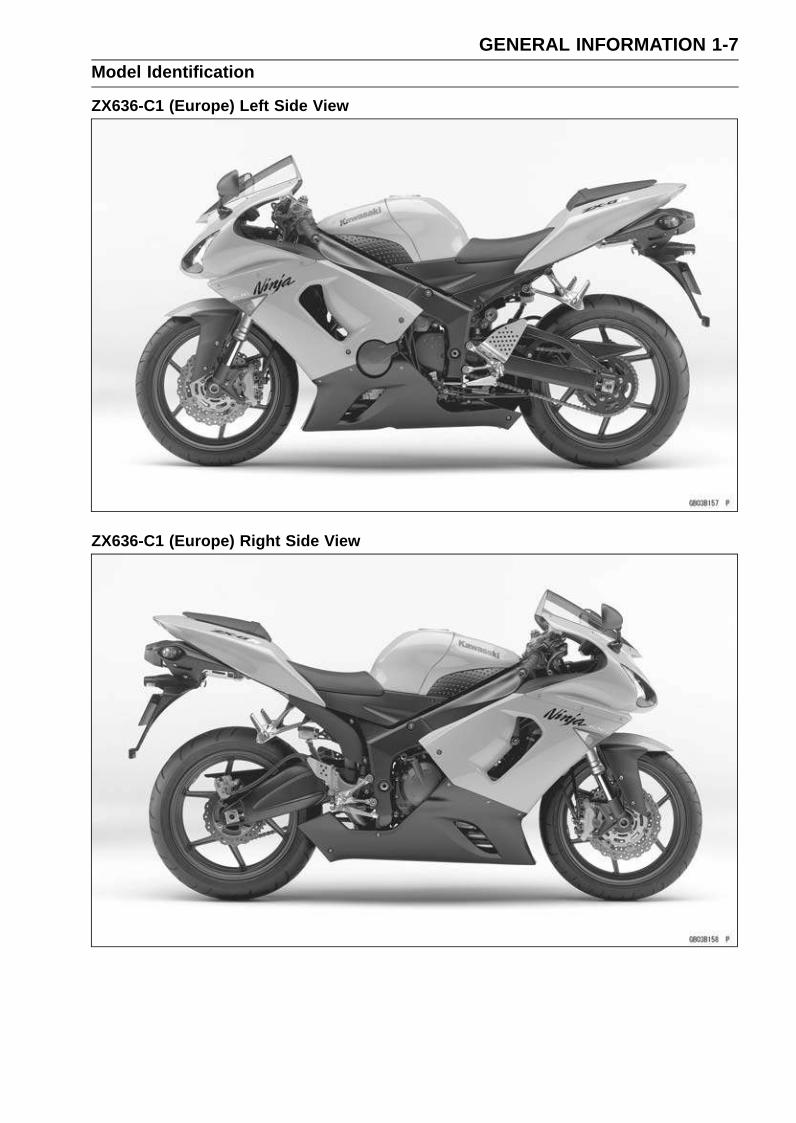
ZX636-C1 (Europe) Left Side View
ZX636-C1 (Europe) Right Side View

1-8 GENERAL INFORMATIONModel Identification
ZX636-C1 (US and Canada) Left Side View
ZX636-C1 (US and Canada) Right Side View
GENERAL INFORMATION 1-9General Specifications
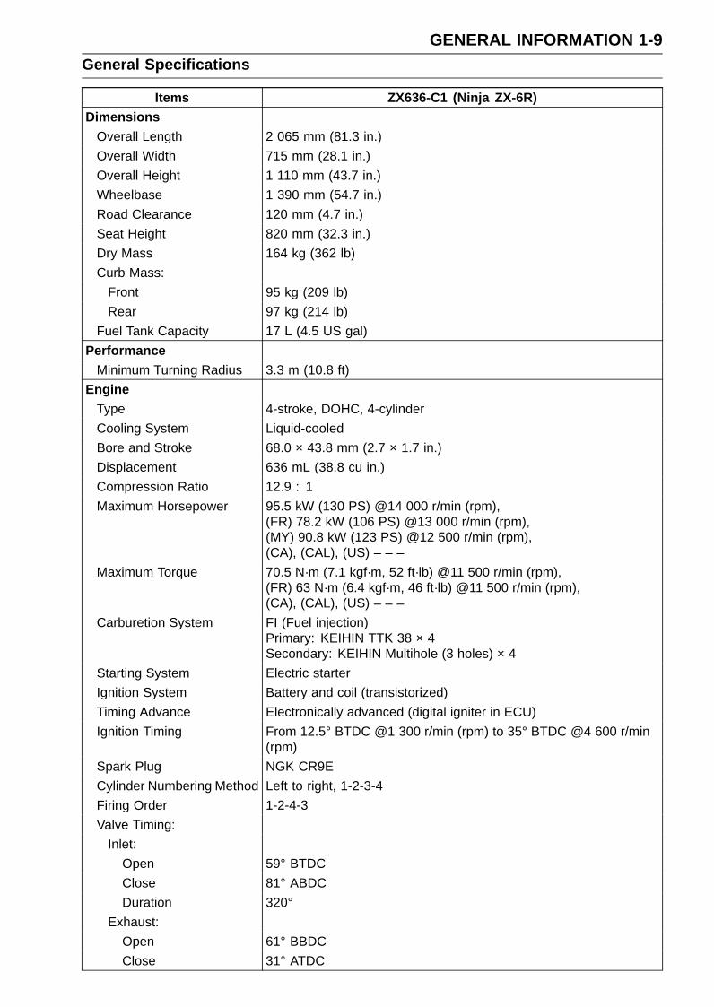
Items ZX636-C1 (Ninja ZX-6R)Dimensions
Overall Length 2 065 mm (81.3 in.)
Overall Width 715 mm (28.1 in.)
Overall Height 1 110 mm (43.7 in.)
Wheelbase 1 390 mm (54.7 in.)
Road Clearance 120 mm (4.7 in.)
Seat Height 820 mm (32.3 in.)
Dry Mass 164 kg (362 lb)
Curb Mass:
Front 95 kg (209 lb)
Rear 97 kg (214 lb)
Fuel Tank Capacity 17 L (4.5 US gal)
PerformanceMinimum Turning Radius 3.3 m (10.8 ft)
EngineType 4-stroke, DOHC, 4-cylinder
Cooling System Liquid-cooled
Bore and Stroke 68.0 × 43.8 mm (2.7 × 1.7 in.)
Displacement 636 mL (38.8 cu in.)
Compression Ratio 12.9 : 1
Maximum Horsepower 95.5 kW (130 PS) @14 000 r/min (rpm),(FR) 78.2 kW (106 PS) @13 000 r/min (rpm),(MY) 90.8 kW (123 PS) @12 500 r/min (rpm),(CA), (CAL), (US) – – –
Maximum Torque 70.5 N·m (7.1 kgf·m, 52 ft·lb) @11 500 r/min (rpm),(FR) 63 N·m (6.4 kgf·m, 46 ft·lb) @11 500 r/min (rpm),(CA), (CAL), (US) – – –
Carburetion System FI (Fuel injection)Primary: KEIHIN TTK 38 × 4Secondary: KEIHIN Multihole (3 holes) × 4
Starting System Electric starter
Ignition System Battery and coil (transistorized)
Timing Advance Electronically advanced (digital igniter in ECU)
Ignition Timing From 12.5° BTDC @1 300 r/min (rpm) to 35° BTDC @4 600 r/min(rpm)
Spark Plug NGK CR9E
Cylinder Numbering Method Left to right, 1-2-3-4
Firing Order 1-2-4-3
Valve Timing:
Inlet:
Open 59° BTDC
Close 81° ABDC
Duration 320°
Exhaust:
Open 61° BBDC
Close 31° ATDC

1-10 GENERAL INFORMATIONGeneral Specifications
Items ZX636-C1 (Ninja ZX-6R)Duration 272°
Lubrication System Forced lubrication (wet sump with cooler)
Engine Oil:
Type API SE, SF or SGAPI SH or SJ with JASO MA
Viscosity SAE10W-40
Capacity 4.0 L (4.2 US qt)
Drive TrainPrimary Reduction System:
Type Gear
Reduction Ratio 1.891 (87/46)
Clutch Type Wet multi disc
Transmission:
Type 6-speed, constant mesh, return shift
Gear Ratios:
1st 2.923 (38/13)
2nd 2.055 (37/18)
3rd 1.666 (35/21)
4th 1.450 (29/20)
5th 1.272 (28/22)
6th 1.153 (30/26)
Final Drive System:
Type Chain drive
Reduction Ratio 2.866 (43/15)
Overall Drive Ratio 6.255 @Top gear
FrameType Tubular, diamond
Caster (Rake Angle) 25°
Trail 106 mm (4.2 in.)
Front Tire:
Type Tubeless
Size 120/65 ZR17 M/C (56 W)
Rear Tire:
Type Tubeless
Size 180/55 ZR17 M/C (73 W)
Front Suspension:
Type Telescopic fork (upside-down)
Wheel Travel 120 mm (4.7 in.)
Rear Suspension:
Type Swingarm (uni-trak)
Wheel Travel 135 mm (5.3 in.)
Brake Type:
Front Dual discs
Rear Single disc
GENERAL INFORMATION 1-11General Specifications
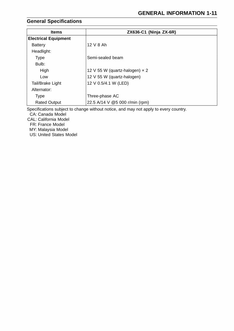
Items ZX636-C1 (Ninja ZX-6R)Electrical Equipment
Battery 12 V 8 Ah
Headlight:
Type Semi-sealed beam
Bulb:
High 12 V 55 W (quartz-halogen) × 2
Low 12 V 55 W (quartz-halogen)
Tail/Brake Light 12 V 0.5/4.1 W (LED)
Alternator:
Type Three-phase AC
Rated Output 22.5 A/14 V @5 000 r/min (rpm)
Specifications subject to change without notice, and may not apply to every country.CA: Canada Model
CAL: California ModelFR: France ModelMY: Malaysia ModelUS: United States Model
1-12 GENERAL INFORMATIONUnit Conversion Table
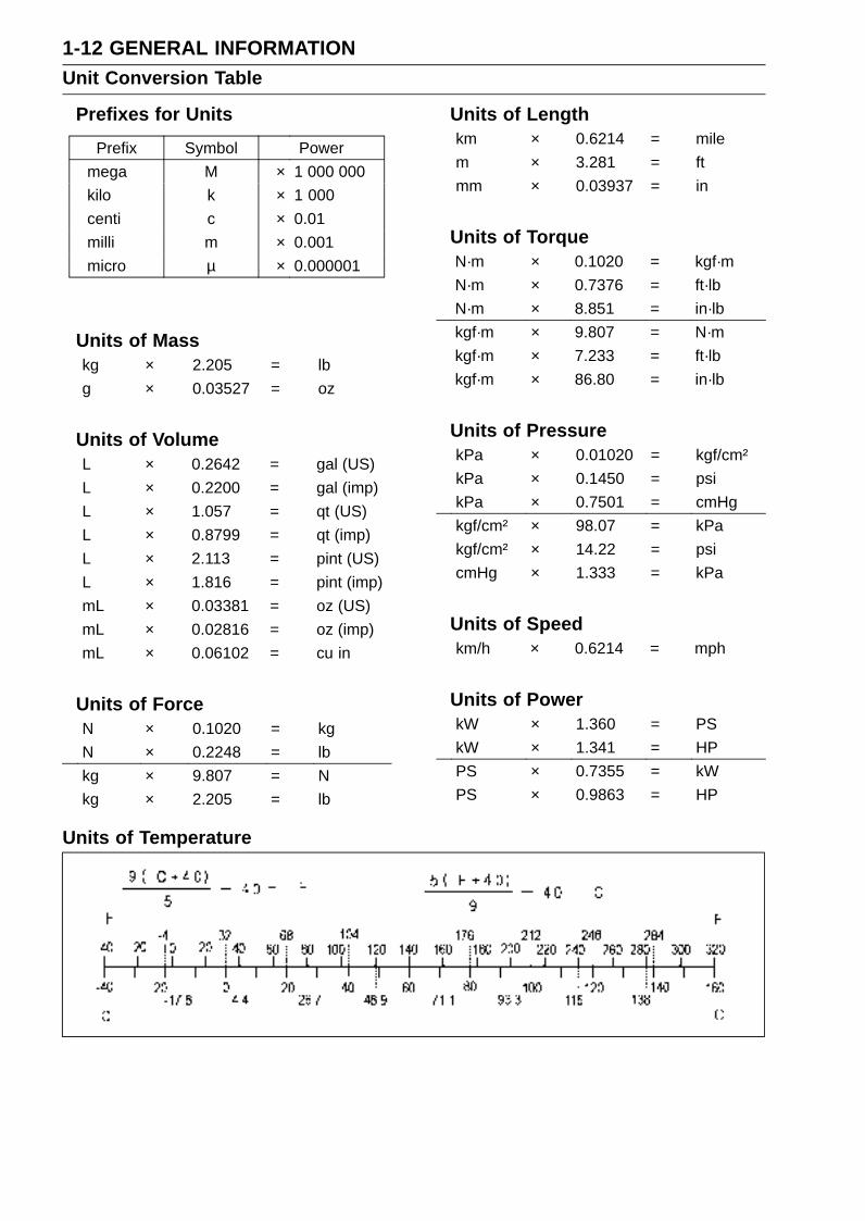
Prefixes for Units
Prefix Symbol Power
mega M × 1 000 000
kilo k × 1 000
centi c × 0.01
milli m × 0.001
micro µ × 0.000001
Units of Masskg × 2.205 = lb
g × 0.03527 = oz
Units of VolumeL × 0.2642 = gal (US)
L × 0.2200 = gal (imp)
L × 1.057 = qt (US)
L × 0.8799 = qt (imp)
L × 2.113 = pint (US)
L × 1.816 = pint (imp)
mL × 0.03381 = oz (US)
mL × 0.02816 = oz (imp)
mL × 0.06102 = cu in
Units of ForceN × 0.1020 = kg
N × 0.2248 = lb
kg × 9.807 = N
kg × 2.205 = lb
Units of Lengthkm × 0.6214 = mile
m × 3.281 = ft
mm × 0.03937 = in
Units of TorqueN·m × 0.1020 = kgf·m
N·m × 0.7376 = ft·lb
N·m × 8.851 = in·lb
kgf·m × 9.807 = N·m
kgf·m × 7.233 = ft·lb
kgf·m × 86.80 = in·lb
Units of PressurekPa × 0.01020 = kgf/cm²
kPa × 0.1450 = psi
kPa × 0.7501 = cmHg
kgf/cm² × 98.07 = kPa
kgf/cm² × 14.22 = psi
cmHg × 1.333 = kPa
Units of Speedkm/h × 0.6214 = mph
Units of PowerkW × 1.360 = PS
kW × 1.341 = HP
PS × 0.7355 = kW
PS × 0.9863 = HP
Units of Temperature
PERIODIC MAINTENANCE 2-1
2
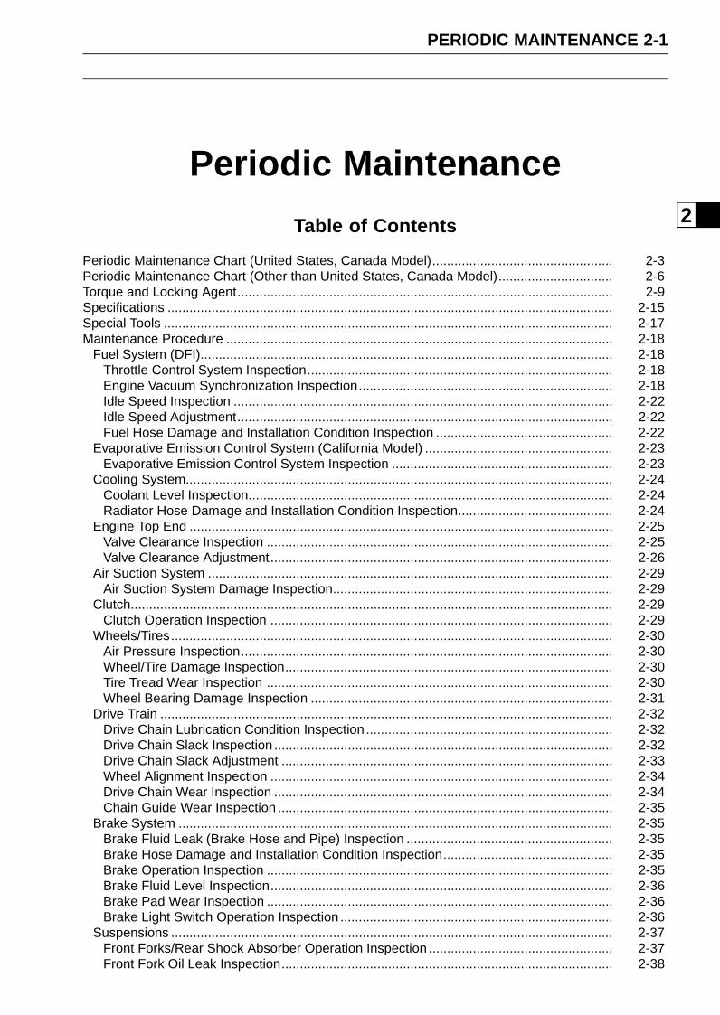
Periodic Maintenance
Table of Contents
Periodic Maintenance Chart (United States, Canada Model)................................................. 2-3Periodic Maintenance Chart (Other than United States, Canada Model)............................... 2-6Torque and Locking Agent...................................................................................................... 2-9Specifications ......................................................................................................................... 2-15Special Tools .......................................................................................................................... 2-17Maintenance Procedure ......................................................................................................... 2-18
Fuel System (DFI)................................................................................................................ 2-18Throttle Control System Inspection................................................................................... 2-18Engine Vacuum Synchronization Inspection..................................................................... 2-18Idle Speed Inspection ....................................................................................................... 2-22Idle Speed Adjustment...................................................................................................... 2-22Fuel Hose Damage and Installation Condition Inspection ................................................ 2-22
Evaporative Emission Control System (California Model) ................................................... 2-23Evaporative Emission Control System Inspection ............................................................ 2-23
Cooling System.................................................................................................................... 2-24Coolant Level Inspection................................................................................................... 2-24Radiator Hose Damage and Installation Condition Inspection.......................................... 2-24
Engine Top End ................................................................................................................... 2-25Valve Clearance Inspection .............................................................................................. 2-25Valve Clearance Adjustment............................................................................................. 2-26
Air Suction System .............................................................................................................. 2-29Air Suction System Damage Inspection............................................................................ 2-29
Clutch................................................................................................................................... 2-29Clutch Operation Inspection ............................................................................................. 2-29
Wheels/Tires........................................................................................................................ 2-30Air Pressure Inspection..................................................................................................... 2-30Wheel/Tire Damage Inspection......................................................................................... 2-30Tire Tread Wear Inspection .............................................................................................. 2-30Wheel Bearing Damage Inspection .................................................................................. 2-31
Drive Train ........................................................................................................................... 2-32Drive Chain Lubrication Condition Inspection ................................................................... 2-32Drive Chain Slack Inspection ............................................................................................ 2-32Drive Chain Slack Adjustment .......................................................................................... 2-33Wheel Alignment Inspection ............................................................................................. 2-34Drive Chain Wear Inspection ............................................................................................ 2-34Chain Guide Wear Inspection ........................................................................................... 2-35
Brake System ...................................................................................................................... 2-35Brake Fluid Leak (Brake Hose and Pipe) Inspection ........................................................ 2-35Brake Hose Damage and Installation Condition Inspection.............................................. 2-35Brake Operation Inspection .............................................................................................. 2-35Brake Fluid Level Inspection............................................................................................. 2-36Brake Pad Wear Inspection .............................................................................................. 2-36Brake Light Switch Operation Inspection .......................................................................... 2-36
Suspensions ........................................................................................................................ 2-37Front Forks/Rear Shock Absorber Operation Inspection .................................................. 2-37Front Fork Oil Leak Inspection.......................................................................................... 2-38

2-2 PERIODIC MAINTENANCE
Rear Shock Absorber Oil Leak Inspection ........................................................................ 2-38Rocker Arm Operation Inspection..................................................................................... 2-38Tie-Rod Operation Inspection ........................................................................................... 2-38
Steering System .................................................................................................................. 2-39Steering Play Inspection ................................................................................................... 2-39Steering Play Adjustment.................................................................................................. 2-39Steering Stem Bearing Lubrication ................................................................................... 2-40
Electrical System ................................................................................................................. 2-40Spark Plug Clean and Gap Inspection.............................................................................. 2-40Lights and Switches Operation Inspection........................................................................ 2-42Headlight Aiming Inspection ............................................................................................. 2-44Side Stand Switch Operation Inspection........................................................................... 2-45Engine Stop Switch Operation Inspection......................................................................... 2-46
Others .................................................................................................................................. 2-47Chassis Parts Lubrication ................................................................................................ 2-47Bolts, Nuts and Fasteners Tightness Inspection............................................................... 2-48
Replacement Parts .............................................................................................................. 2-50Air Cleaner Element Replacement.................................................................................... 2-50Fuel Hose Replacement ................................................................................................... 2-50Coolant Change................................................................................................................ 2-52Radiator Hose and O-ring Replacement........................................................................... 2-54Engine Oil Change............................................................................................................ 2-55Oil Filter Replacement ...................................................................................................... 2-55Brake Hose and Pipe Replacement.................................................................................. 2-56Brake Fluid Change .......................................................................................................... 2-56Master Cylinder Rubber Parts Replacement .................................................................... 2-58Caliper Rubber Parts Replacement .................................................................................. 2-59Spark Plug Replacement .................................................................................................. 2-62
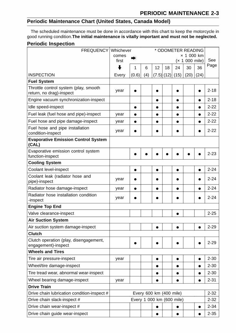
PERIODIC MAINTENANCE 2-3Periodic Maintenance Chart (United States, Canada Model)
The scheduled maintenance must be done in accordance with this chart to keep the motorcycle ingood running condition.The initial maintenance is vitally important and must not be neglected.
Periodic InspectionFREQUENCY Whichever
comesfirst
* ODOMETER READING× 1 000 km
(× 1 000 mile)
1 6 12 18 24 30 36
INSPECTION Every (0.6) (4) (7.5) (12) (15) (20) (24)
SeePage
Fuel SystemThrottle control system (play, smoothreturn, no drag)-inspect
year • • • • 2-18
Engine vacuum synchronization-inspect • • • 2-18
Idle speed-inspect • • • • 2-22
Fuel leak (fuel hose and pipe)-inspect year • • • • 2-22
Fuel hose and pipe damage-inspect year • • • • 2-22
Fuel hose and pipe installationcondition-inspect
year • • • • 2-22
Evaporative Emission Control System(CAL)Evaporative emission control systemfunction-inspect • • • • • • • 2-23
Cooling System
Coolant level-inspect • • • • 2-24
Coolant leak (radiator hose andpipe)-inspect
year • • • • 2-24
Radiator hose damage-inspect year • • • • 2-24
Radiator hose installation condition-inspect
year • • • • 2-24
Engine Top End
Valve clearance-inspect • 2-25
Air Suction System
Air suction system damage-inspect • • • 2-29
ClutchClutch operation (play, disengagement,engagement)-inspect • • • • 2-29
Wheels and Tires
Tire air pressure-inspect year • • • 2-30
Wheel/tire damage-inspect • • • 2-30
Tire tread wear, abnormal wear-inspect • • • 2-30
Wheel bearing damage-inspect year • • • 2-31
Drive TrainDrive chain lubrication condition-inspect # Every 600 km (400 mile) 2-32
Drive chain slack-inspect # Every 1 000 km (600 mile) 2-32
Drive chain wear-inspect # • • • 2-34
Drive chain guide wear-inspect • • • 2-35
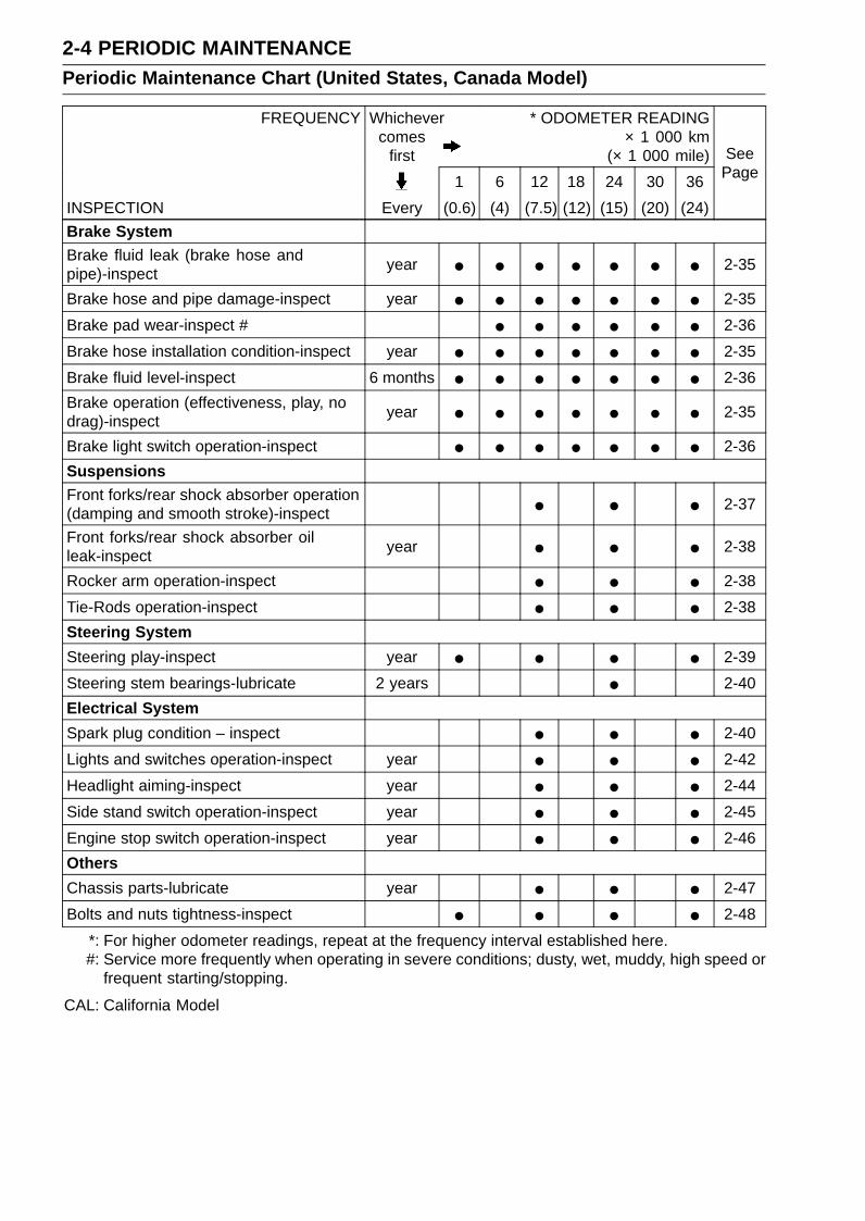
2-4 PERIODIC MAINTENANCEPeriodic Maintenance Chart (United States, Canada Model)
FREQUENCY Whichevercomes
first
* ODOMETER READING× 1 000 km
(× 1 000 mile)
1 6 12 18 24 30 36
INSPECTION Every (0.6) (4) (7.5) (12) (15) (20) (24)
SeePage
Brake SystemBrake fluid leak (brake hose andpipe)-inspect
year • • • • • • • 2-35
Brake hose and pipe damage-inspect year • • • • • • • 2-35
Brake pad wear-inspect # • • • • • • 2-36
Brake hose installation condition-inspect year • • • • • • • 2-35
Brake fluid level-inspect 6 months • • • • • • • 2-36
Brake operation (effectiveness, play, nodrag)-inspect
year • • • • • • • 2-35
Brake light switch operation-inspect • • • • • • • 2-36
SuspensionsFront forks/rear shock absorber operation(damping and smooth stroke)-inspect • • • 2-37
Front forks/rear shock absorber oilleak-inspect
year • • • 2-38
Rocker arm operation-inspect • • • 2-38
Tie-Rods operation-inspect • • • 2-38
Steering System
Steering play-inspect year • • • • 2-39
Steering stem bearings-lubricate 2 years • 2-40
Electrical System
Spark plug condition – inspect • • • 2-40
Lights and switches operation-inspect year • • • 2-42
Headlight aiming-inspect year • • • 2-44
Side stand switch operation-inspect year • • • 2-45
Engine stop switch operation-inspect year • • • 2-46
Others
Chassis parts-lubricate year • • • 2-47
Bolts and nuts tightness-inspect • • • • 2-48
*: For higher odometer readings, repeat at the frequency interval established here.#: Service more frequently when operating in severe conditions; dusty, wet, muddy, high speed or
frequent starting/stopping.
CAL: California Model
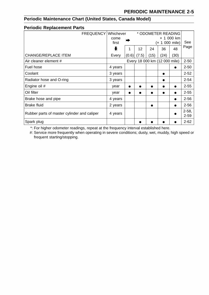
PERIODIC MAINTENANCE 2-5Periodic Maintenance Chart (United States, Canada Model)
Periodic Replacement PartsFREQUENCY Whichever
comefirst
* ODOMETER READING× 1 000 km
(× 1 000 mile)
1 12 24 36 48
CHANGE/REPLACE ITEM Every (0.6) (7.5) (15) (24) (30)
SeePage
Air cleaner element # Every 18 000 km (12 000 mile) 2-50
Fuel hose 4 years • 2-50
Coolant 3 years • 2-52
Radiator hose and O-ring 3 years • 2-54
Engine oil # year • • • • • 2-55
Oil filter year • • • • • 2-55
Brake hose and pipe 4 years • 2-56
Brake fluid 2 years • • 2-56
Rubber parts of master cylinder and caliper 4 years • 2-58,2-59
Spark plug • • • • 2-62
*: For higher odometer readings, repeat at the frequency interval established here.#: Service more frequently when operating in severe conditions; dusty, wet, muddy, high speed or
frequent starting/stopping.
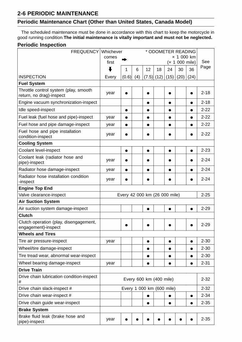
2-6 PERIODIC MAINTENANCEPeriodic Maintenance Chart (Other than United States, Canada Model)
The scheduled maintenance must be done in accordance with this chart to keep the motorcycle ingood running condition.The initial maintenance is vitally important and must not be neglected.
Periodic InspectionFREQUENCY Whichever
comesfirst
* ODOMETER READING× 1 000 km
(× 1 000 mile)
1 6 12 18 24 30 36
INSPECTION Every (0.6) (4) (7.5) (12) (15) (20) (24)
SeePage
Fuel SystemThrottle control system (play, smoothreturn, no drag)-inspect
year • • • • 2-18
Engine vacuum synchronization-inspect • • • 2-18
Idle speed-inspect • • • • 2-22
Fuel leak (fuel hose and pipe)-inspect year • • • • 2-22
Fuel hose and pipe damage-inspect year • • • • 2-22
Fuel hose and pipe installationcondition-inspect
year • • • • 2-22
Cooling System
Coolant level-inspect • • • • 2-23
Coolant leak (radiator hose andpipe)-inspect
year • • • • 2-24
Radiator hose damage-inspect year • • • • 2-24
Radiator hose installation condition-inspect
year • • • • 2-24
Engine Top EndValve clearance-inspect Every 42 000 km (26 000 mile) 2-25
Air Suction System
Air suction system damage-inspect • • • 2-29
ClutchClutch operation (play, disengagement,engagement)-inspect • • • • 2-29
Wheels and Tires
Tire air pressure-inspect year • • • 2-30
Wheel/tire damage-inspect • • • 2-30
Tire tread wear, abnormal wear-inspect • • • 2-30
Wheel bearing damage-inspect year • • • 2-31
Drive TrainDrive chain lubrication condition-inspect#
Every 600 km (400 mile) 2-32
Drive chain slack-inspect # Every 1 000 km (600 mile) 2-32
Drive chain wear-inspect # • • • 2-34
Drive chain guide wear-inspect • • • 2-35
Brake SystemBrake fluid leak (brake hose andpipe)-inspect
year • • • • • • • 2-35

PERIODIC MAINTENANCE 2-7Periodic Maintenance Chart (Other than United States, Canada Model)
FREQUENCY Whichevercomes
first
* ODOMETER READING× 1 000 km
(× 1 000 mile)
1 6 12 18 24 30 36
INSPECTION Every (0.6) (4) (7.5) (12) (15) (20) (24)
SeePage
Brake hose and pipe damage-inspect year • • • • • • • 2-35
Brake pad wear-inspect # • • • • • • 2-36
Brake hose installation condition-inspect year • • • • • • • 2-35
Brake fluid level-inspect 6 months • • • • • • • 2-36
Brake operation (effectiveness, play, nodrag)-inspect
year • • • • • • • 2-35
Brake light switch operation-inspect • • • • • • • 2-36
SuspensionsFront forks/rear shock absorberoperation (damping and smoothstroke)-inspect
• • • 2-37
Front forks/rear shock absorber oilleak-inspect
year • • • 2-38
Rocker arm operation-inspect • • • 2-38
Tie-Rods operation-inspect • • • 2-38
Steering System
Steering play-inspect year • • • • 2-39
Steering stem bearings-lubricate 2 years • 2-40
Electrical System
Spark plug condition – inspect • • • 2-40
Lights and switches operation-inspect year • • • 2-42
Headlight aiming-inspect year • • • 2-44
Side stand switch operation-inspect year • • • 2-45
Engine stop switch operation-inspect year • • • 2-46
Others
Chassis parts-lubricate year • • • 2-47
Bolts and nuts tightness-inspect • • • • 2-48
*: For higher odometer readings, repeat at the frequency interval established here.#: Service more frequently when operating in severe conditions; dusty, wet, muddy, high speed or
frequent starting/stopping.

2-8 PERIODIC MAINTENANCEPeriodic Maintenance Chart (Other than United States, Canada Model)
Periodic Replacement PartsFREQUENCY Whichever
comefirst
* ODOMETER READING× 1 000 km
(× 1 000 mile)
1 12 24 36 48
CHANGE/REPLACE ITEM Every (0.6) (7.5) (15) (24) (30)
SeePage
Air cleaner element # Every 18 000 km (12 000 mile) 2-50
Fuel hose 4 years • 2-50
Coolant 3 years • 2-52
Radiator hose and O-ring 3 years • 2-54
Engine oil # year • • • • • 2-55
Oil filter year • • • • • 2-55
Brake hose and pipe 4 years • 2-56
Brake fluid 2 years • • 2-56
Rubber parts of master cylinder and caliper 4 years • 2-58,2-59
Spark plug • • • • 2-62
*: For higher odometer readings, repeat at the frequency interval established here.#: Service more frequently when operating in severe conditions; dusty, wet, muddy, high speed or
frequent starting/stopping.
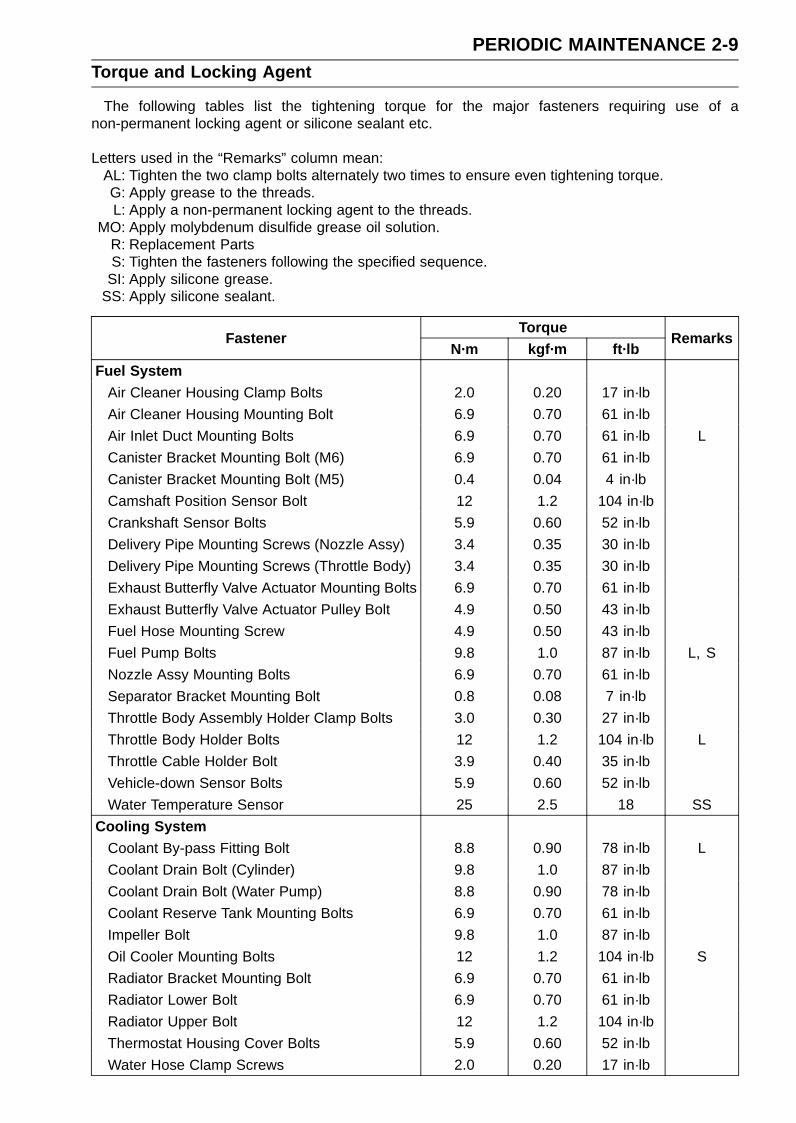
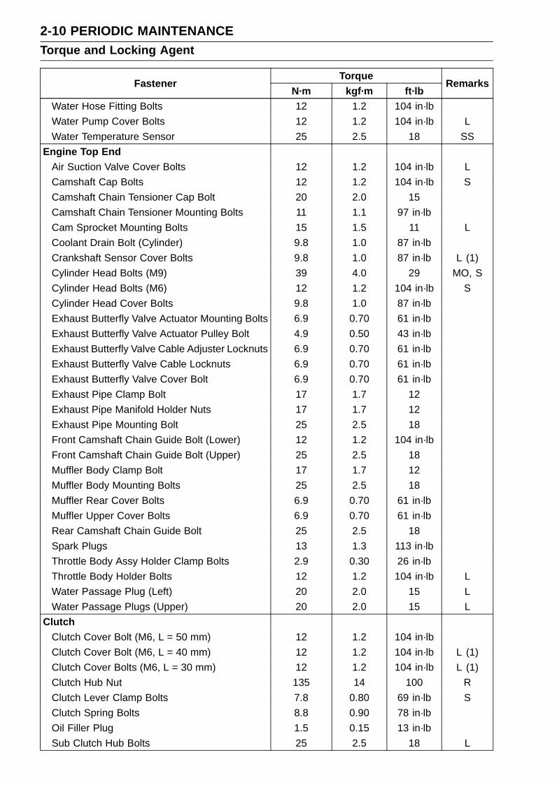
PERIODIC MAINTENANCE 2-9Torque and Locking Agent
The following tables list the tightening torque for the major fasteners requiring use of anon-permanent locking agent or silicone sealant etc.
Letters used in the “Remarks” column mean:AL: Tighten the two clamp bolts alternately two times to ensure even tightening torque.G: Apply grease to the threads.L: Apply a non-permanent locking agent to the threads.
MO: Apply molybdenum disulfide grease oil solution.R: Replacement PartsS: Tighten the fasteners following the specified sequence.
SI: Apply silicone grease.SS: Apply silicone sealant.
TorqueFastener
N·m kgf·m ft·lbRemarks
Fuel SystemAir Cleaner Housing Clamp Bolts 2.0 0.20 17 in·lb
Air Cleaner Housing Mounting Bolt 6.9 0.70 61 in·lb
Air Inlet Duct Mounting Bolts 6.9 0.70 61 in·lb L
Canister Bracket Mounting Bolt (M6) 6.9 0.70 61 in·lb
Canister Bracket Mounting Bolt (M5) 0.4 0.04 4 in·lb
Camshaft Position Sensor Bolt 12 1.2 104 in·lb
Crankshaft Sensor Bolts 5.9 0.60 52 in·lb
Delivery Pipe Mounting Screws (Nozzle Assy) 3.4 0.35 30 in·lb
Delivery Pipe Mounting Screws (Throttle Body) 3.4 0.35 30 in·lb
Exhaust Butterfly Valve Actuator Mounting Bolts 6.9 0.70 61 in·lb
Exhaust Butterfly Valve Actuator Pulley Bolt 4.9 0.50 43 in·lb
Fuel Hose Mounting Screw 4.9 0.50 43 in·lb
Fuel Pump Bolts 9.8 1.0 87 in·lb L, S
Nozzle Assy Mounting Bolts 6.9 0.70 61 in·lb
Separator Bracket Mounting Bolt 0.8 0.08 7 in·lb
Throttle Body Assembly Holder Clamp Bolts 3.0 0.30 27 in·lb
Throttle Body Holder Bolts 12 1.2 104 in·lb L
Throttle Cable Holder Bolt 3.9 0.40 35 in·lb
Vehicle-down Sensor Bolts 5.9 0.60 52 in·lb
Water Temperature Sensor 25 2.5 18 SS
Cooling SystemCoolant By-pass Fitting Bolt 8.8 0.90 78 in·lb L
Coolant Drain Bolt (Cylinder) 9.8 1.0 87 in·lb
Coolant Drain Bolt (Water Pump) 8.8 0.90 78 in·lb
Coolant Reserve Tank Mounting Bolts 6.9 0.70 61 in·lb
Impeller Bolt 9.8 1.0 87 in·lb
Oil Cooler Mounting Bolts 12 1.2 104 in·lb S
Radiator Bracket Mounting Bolt 6.9 0.70 61 in·lb
Radiator Lower Bolt 6.9 0.70 61 in·lb
Radiator Upper Bolt 12 1.2 104 in·lb
Thermostat Housing Cover Bolts 5.9 0.60 52 in·lb
Water Hose Clamp Screws 2.0 0.20 17 in·lb
2-10 PERIODIC MAINTENANCETorque and Locking Agent
TorqueFastener
N·m kgf·m ft·lbRemarks
Water Hose Fitting Bolts 12 1.2 104 in·lb
Water Pump Cover Bolts 12 1.2 104 in·lb L
Water Temperature Sensor 25 2.5 18 SS
Engine Top EndAir Suction Valve Cover Bolts 12 1.2 104 in·lb L
Camshaft Cap Bolts 12 1.2 104 in·lb S
Camshaft Chain Tensioner Cap Bolt 20 2.0 15
Camshaft Chain Tensioner Mounting Bolts 11 1.1 97 in·lb
Cam Sprocket Mounting Bolts 15 1.5 11 L
Coolant Drain Bolt (Cylinder) 9.8 1.0 87 in·lb
Crankshaft Sensor Cover Bolts 9.8 1.0 87 in·lb L (1)
Cylinder Head Bolts (M9) 39 4.0 29 MO, S
Cylinder Head Bolts (M6) 12 1.2 104 in·lb S
Cylinder Head Cover Bolts 9.8 1.0 87 in·lb
Exhaust Butterfly Valve Actuator Mounting Bolts 6.9 0.70 61 in·lb
Exhaust Butterfly Valve Actuator Pulley Bolt 4.9 0.50 43 in·lb
Exhaust Butterfly Valve Cable Adjuster Locknuts 6.9 0.70 61 in·lb
Exhaust Butterfly Valve Cable Locknuts 6.9 0.70 61 in·lb
Exhaust Butterfly Valve Cover Bolt 6.9 0.70 61 in·lb
Exhaust Pipe Clamp Bolt 17 1.7 12
Exhaust Pipe Manifold Holder Nuts 17 1.7 12
Exhaust Pipe Mounting Bolt 25 2.5 18
Front Camshaft Chain Guide Bolt (Lower) 12 1.2 104 in·lb
Front Camshaft Chain Guide Bolt (Upper) 25 2.5 18
Muffler Body Clamp Bolt 17 1.7 12
Muffler Body Mounting Bolts 25 2.5 18
Muffler Rear Cover Bolts 6.9 0.70 61 in·lb
Muffler Upper Cover Bolts 6.9 0.70 61 in·lb
Rear Camshaft Chain Guide Bolt 25 2.5 18
Spark Plugs 13 1.3 113 in·lb
Throttle Body Assy Holder Clamp Bolts 2.9 0.30 26 in·lb
Throttle Body Holder Bolts 12 1.2 104 in·lb L
Water Passage Plug (Left) 20 2.0 15 L
Water Passage Plugs (Upper) 20 2.0 15 L
ClutchClutch Cover Bolt (M6, L = 50 mm) 12 1.2 104 in·lb
Clutch Cover Bolt (M6, L = 40 mm) 12 1.2 104 in·lb L (1)
Clutch Cover Bolts (M6, L = 30 mm) 12 1.2 104 in·lb L (1)
Clutch Hub Nut 135 14 100 R
Clutch Lever Clamp Bolts 7.8 0.80 69 in·lb S
Clutch Spring Bolts 8.8 0.90 78 in·lb
Oil Filler Plug 1.5 0.15 13 in·lb
Sub Clutch Hub Bolts 25 2.5 18 L

PERIODIC MAINTENANCE 2-11Torque and Locking Agent
TorqueFastener
N·m kgf·m ft·lbRemarks
Engine Lubrication SystemCoolant Drain Bolt (Water Pump) 8.8 0.90 78 in·lb
Engine Oil Drain Bolt 29 3.0 22
Impeller Bolt 9.8 1.0 87 in·lb
Oil Cooler Mounting Bolts 12 1.2 104 in·lb S
Oil Filter 31 3.2 23 EO, R
Oil Filter Mounting Bolt 25 2.5 18 L
Oil Jet Nozzle Bolts 6.9 0.70 61 in·lb L
Oil Pan Bolts 9.8 1.0 87 in·lb
Oil Pan Clamp Bolt 9.8 1.0 87 in·lb
Oil Passage Plug (Left Side) 20 2.0 15 L
Oil Passage Plug (Right Side) 15 1.5 11
Oil Pipe Bolts 12 1.2 104 in·lb
Oil Pressure Relief Valve 15 1.5 11 L
Oil Pressure Switch 15 1.5 11 SS
Oil Pressure Switch Terminal Bolt 1.5 0.15 13 in·lb
Water Hose Clamp Screws 2.0 0.20 17 in·lb
Water Pump Cover Bolts 12 1.2 104 in·lb L
Engine Removal/InstallationAdjusting Collar Locknut 49 5.0 36 S
Lower Engine Mounting Bolt 10 1.0 87 in·lb S
Lower Engine Mounting Nut 44 4.5 33 S
Middle Engine Mounting Bolt 10 1.0 87 in·lb S
Middle Engine Mounting Nut 44 4.5 33 S
Upper Engine Mounting Bolts 44 4.5 33 S
Crankshaft/TransmissionBreather Plate Bolts 5.9 0.60 52 in·lb L
Connecting Rod Big End Nuts see the text ← ← ←Crankcase Bolts (M8) 31 3.2 23 MO, S
Crankcase Bolts (M7, L = 38 mm) 27 2.8 20 S
Crankcase Bolt (M7, L = 70 mm) 20 2.0 14 S
Crankcase Bolts (M6, L = 65 mm) 12 1.2 104 in·lb S
Crankcase Bolts (M6, L = 50 mm) 12 1.2 104 in·lb S
Crankcase Bolts (M6, L = 38 mm) 12 1.2 104 in·lb S
Crankcase Bolt (M6, L = 95 mm) 12 1.2 104 in·lb S
Crankcase Bolt (M6, L = 85 mm) 12 1.2 104 in·lb S
Crankcase Bolt (M6, L = 35 mm) 12 1.2 104 in·lb S
Neutral Switch 15 1.5 11 L
Gear Positioning Lever Bolt 12 1.2 104 in·lb
Harness Clamp Bolt 8.8 0.90 78 in·lb L
Oil Passage Plug (Left Side) 20 2.0 15 L
Oil Passage Plug (Right Side) 15 1.5 11
Oil Pressure Switch 15 1.5 11 SS

2-12 PERIODIC MAINTENANCETorque and Locking Agent
TorqueFastener
N·m kgf·m ft·lbRemarks
Oil Pressure Switch Terminal Bolt 1.5 0.15 13 in·lb
Plate Screws 5.9 0.60 52 in·lb L
Shift Drum Bearing Holder Bolts 12 1.2 104 in·lb L
Shift Drum Cam Holder Bolt 12 1.2 104 in·lb L
Shift Lever Bolt 6.9 0.70 61 in·lb
Shift Pedal Mounting Bolt 25 2.5 18
Shift Shaft Return Spring Pin 28 2.9 21 L
Tie-Rod Locknuts 6.9 0.70 61 in·lb
Wheels/TiresFront Axle Clamp Bolts 20 2.0 15 AL
Front Axle Nut 127 13 94
Rear Axle Nut 127 13 94
Final DriveEngine Sprocket Cover Bolts 6.9 0.70 61 in·lb
Engine Sprocket Nut 125 13 92 MO
Rear Axle Nut 127 13 94
Rear Sprocket Nuts 59 6.0 43
BrakesBleed Valves 7.8 0.80 69 in·lb
Brake Hose Banjo Bolts 34 3.5 25
Brake Lever Pivot Bolt 1.0 0.10 9 in·lb SI
Brake Lever Pivot Bolt Locknut 5.9 0.60 52 in·lb
Brake Pedal Bolt 8.8 0.90 78
Front Brake Light Switch Screw 1.2 0.12 10 in·lb
Front Brake Reservoir Cap Stopper Screw 1.2 0.12 10 in·lb
Front Brake Disc Mounting Bolts 27 2.8 20 L
Front Brake Pad Pins 15 1.5 11
Front Caliper Assembly Bolts 22 2.2 16
Front Caliper Mounting Bolts 34 3.5 25
Front Master Cylinder Bleed Valve 5.9 0.60 52 in·lb
Front Master Cylinder Clamp Bolts 8.8 0.90 78 in·lb S
Rear Brake Disc Mounting Bolts 27 2.8 20 L
Rear Caliper Mounting Bolts 25 2.5 18
Rear Master Cylinder Mounting Bolts 25 2.5 18
Rear Master Cylinder Push Rod Locknut 18 1.8 13
SuspensionFront Axle Clamp Bolts 20 2.0 15 AL
Front Fork Bottom Allen Bolts 35 3.5 26 L
Front Fork Clamp Bolts (Lower) 25 2.5 18 AL
Front Fork Clamp Bolts (Upper) 20 2.0 15
Front Fork Top Plugs 35 3.5 26
Piston Rod Nuts 20 2.0 15
Rear Shock Absorber Bracket Nut 59 6.0 43

PERIODIC MAINTENANCE 2-13Torque and Locking Agent
TorqueFastener
N·m kgf·m ft·lbRemarks
Rear Shock Absorber Nut (Lower) 34 3.5 25
Rear Shock Absorber Nut (Upper) 34 3.5 25
Swingarm Pivot Adjusting Collar 20 2.0 15
Swingarm Pivot Adjusting Collar Locknut 98 10 72
Swingarm Pivot Shaft Nut 108 11 81
Tie-Rod Nuts 59 6.0 43
Uni-Trak Rocker Arm Nut 34 3.5 25
SteeringFront Fork Clamp Bolts (Lower) 25 2.5 18 AL
Front Fork Clamp Bolts (Upper) 20 2.0 15
Handlebar Bolts 25 2.5 18
Handlebar Position Bolts 9.8 1.0 87 in·lb L
Steering Stem Head Nut 78 8.0 58
Steering Stem Nut 20 2.0 15
Switch Housing Screws 3.5 0.36 31 in·lb
FrameAir Inlet Duct Mounting Bolts 6.9 0.70 61 L
Front Fender Mounting Bolts 3.9 0.40 35 in·lb
Front Footpeg Bracket Bolts 25 2.5 18
Rear Footpeg Bracket Bolts 25 2.5 18
Rear Frame Bolts 59 6.0 44 L (2)
Side Stand Bolt 44 4.5 32 G
Side Stand Bracket Bolts 49 5.0 36 L
Side Stand Switch Bolt 8.8 0.90 78 in·lb L
Side Stand Switch Bracket Bolt 3.9 0.40 35 in·lb L
Windshield Mounting Bolts 0.4 0.04 4 in·lb
Electrical SystemAlternator Cover Bolts 12 1.2 104 in·lb
Alternator Lead Holding Plate Bolts 6.9 0.70 61 in·lb L
Alternator Rotor Bolt 110 11 81
Camshaft Position Sensor Bolt 12 1.2 104 in·lb
Crankshaft Sensor Bolts 5.9 0.60 52 in·lb
Crankshaft Sensor Cover Bolts 9.8 1.0 87 in·lb L (1)
Engine Ground Lead Terminal Bolt 9.8 1.0 87 in·lb
Front Brake Light Switch Screw 1.2 0.12 10 in·lb
Front Turn Signal Light Lens Screws 1.0 0.10 9 in·lb
Front Turn Signal Light Mounting Screws 1.2 0.12 10 in·lb
Headlight Mounting Screws 1.2 0.12 10 in·lb
Licence Light Assembly Screws 0.9 0.09 8 in·lb
Licence Light Mounting Screws 1.2 0.12 10 in·lb
Meter Mounting Screws 1.2 0.12 10 in·lb
Neutral Switch 15 1.5 11 L
Rear Turn Signal Light Lens Screws 1.0 0.10 9 in·lb
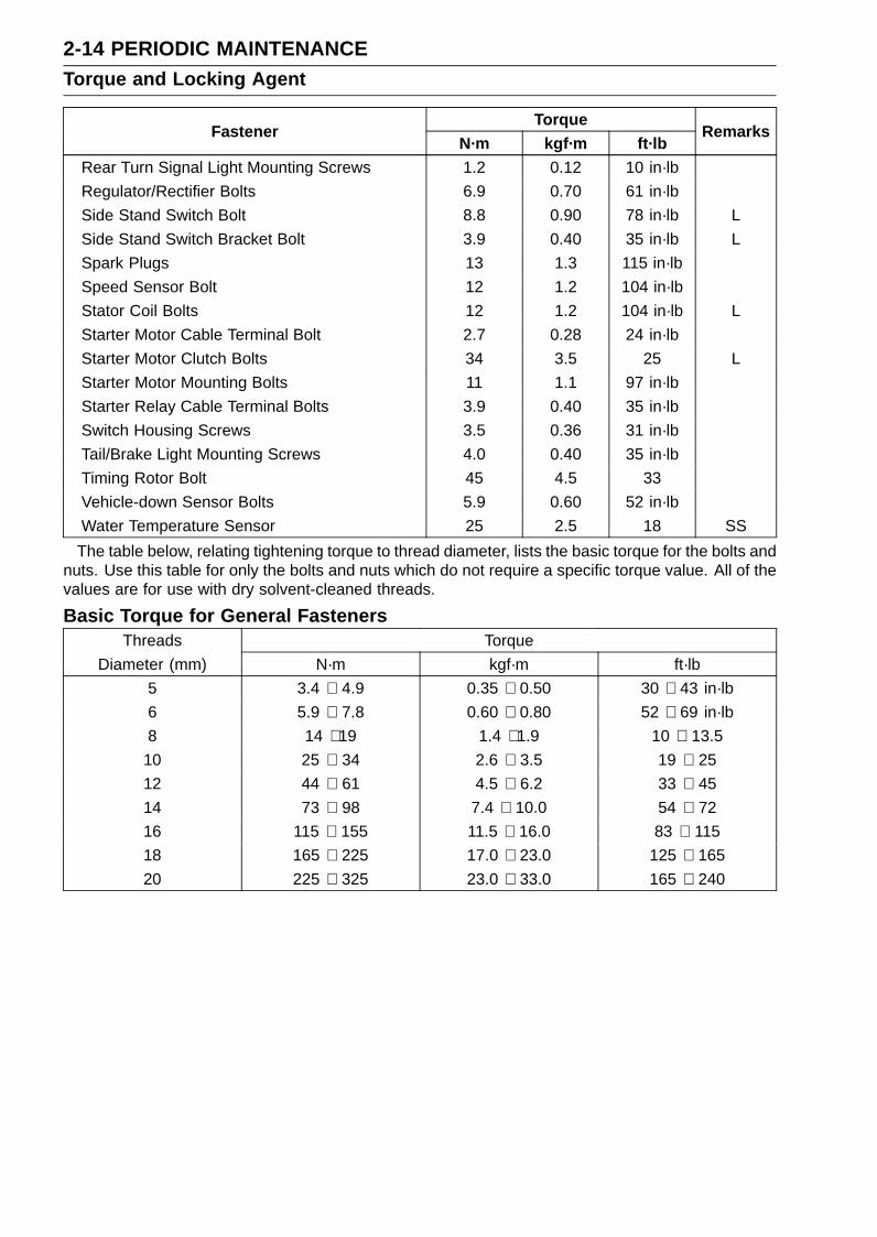
2-14 PERIODIC MAINTENANCETorque and Locking Agent
TorqueFastener
N·m kgf·m ft·lbRemarks
Rear Turn Signal Light Mounting Screws 1.2 0.12 10 in·lb
Regulator/Rectifier Bolts 6.9 0.70 61 in·lb
Side Stand Switch Bolt 8.8 0.90 78 in·lb L
Side Stand Switch Bracket Bolt 3.9 0.40 35 in·lb L
Spark Plugs 13 1.3 115 in·lb
Speed Sensor Bolt 12 1.2 104 in·lb
Stator Coil Bolts 12 1.2 104 in·lb L
Starter Motor Cable Terminal Bolt 2.7 0.28 24 in·lb
Starter Motor Clutch Bolts 34 3.5 25 L
Starter Motor Mounting Bolts 11 1.1 97 in·lb
Starter Relay Cable Terminal Bolts 3.9 0.40 35 in·lb
Switch Housing Screws 3.5 0.36 31 in·lb
Tail/Brake Light Mounting Screws 4.0 0.40 35 in·lb
Timing Rotor Bolt 45 4.5 33
Vehicle-down Sensor Bolts 5.9 0.60 52 in·lb
Water Temperature Sensor 25 2.5 18 SS
The table below, relating tightening torque to thread diameter, lists the basic torque for the bolts andnuts. Use this table for only the bolts and nuts which do not require a specific torque value. All of thevalues are for use with dry solvent-cleaned threads.
Basic Torque for General FastenersThreads Torque
Diameter (mm) N·m kgf·m ft·lb
5 3.4 ∼ 4.9 0.35 ∼ 0.50 30 ∼ 43 in·lb
6 5.9 ∼ 7.8 0.60 ∼ 0.80 52 ∼ 69 in·lb
8 14 ∼ 19 1.4 ∼ 1.9 10 ∼ 13.5
10 25 ∼ 34 2.6 ∼ 3.5 19 ∼ 25
12 44 ∼ 61 4.5 ∼ 6.2 33 ∼ 45
14 73 ∼ 98 7.4 ∼ 10.0 54 ∼ 72
16 115 ∼ 155 11.5 ∼ 16.0 83 ∼ 115
18 165 ∼ 225 17.0 ∼ 23.0 125 ∼ 165
20 225 ∼ 325 23.0 ∼ 33.0 165 ∼ 240

PERIODIC MAINTENANCE 2-15Specifications
Item Standard Service LimitFuel System
Throttle Grip Free Play 2 ∼ 3 mm (0.08 ∼ 0.12 in.) – – –
Idle Speed 1 300 ±50 r/min (rpm) – – –
Throttle Body Vacuum 27.3 ±1.3 kPa (205 ±10 mmHg) at idle speed – – –
Air Cleaner Element Viscous paper element – – –
Cooling SystemCoolant:
Type (Recommended) Permanent type antifreeze – – –
Color Green – – –
Mixed Ratio Soft water 50%, coolant 50% – – –
Freezing Point –35°C (–31°F) – – –
Total Amount 2.6 L (2.7 US qt) – – –
Engine Top EndValve Clearance:
Exhaust 0.22 ∼ 0.31 mm (0.0087 ∼ 0.0122 in.) – – –
Inlet 0.11 ∼ 0.19 mm (0.0043 ∼ 0.0075 in.) – – –
ClutchClutch Lever Free Play 2 ∼ 3 mm (0.08 ∼ 0.12 in.) – – –
Engine Lubrication SystemEngine Oil:
Type API SE, SF or SGAPI SH or SJ with JASO MA
– – –
Viscosity SAE 10W-40 – – –
Capacity 3.4 L (3.6 US qt) (when filter is not removed) – – –
3.6 L (3.8 US qt) (when filter is removed) – – –
4.0 L (4.2 US qt) (when engine is completely dry) – – –
Level Between upper and lower level lines (Wait 2 ∼ 3minutes after idling or running)
– – –
TiresTread Depth:
Front BRIDGESTONE: 3.6 mm (0.14 in.) 1 mm (0.04 in.),(AT, CH, DE) 1.6mm (0.06 in.)
Rear BRIDGESTONE: 5.8 mm (0.23 in.) Up to 130 km/h(80 mph): 2 mm(0.08 in.), Over130 km/h (80mph): 3 mm (0.12in.)
Air Pressure (when Cold):
Front Up to 180 kg (397 lb) load: 250 kPa (2.5 kgf/cm²,36 psi)
– – –
Rear Up to 180 kg (397 lb) load: 290 kPa (2.9 kgf/cm²,42 psi)
– – –

2-16 PERIODIC MAINTENANCESpecifications
Item Standard Service LimitFinal Drive
Drive Chain Slack 30 ∼ 35 mm (1.2 ∼ 1.4 in.) – – –
Drive Chain Wear (20-linkLength)
317.5 ∼ 318.2 mm (12.50 ∼ 12.53 in.) 323 mm (12.7 in.)
Standard Chain:
Make ENUMA – – –
Type EK520MVXL – – –
Link 110 links – – –
BrakesBrake Fluid:
Grade DOT4 – – –
Brake Pad LiningThickness:
Front 4.0 mm (0.16 in.) 1 mm (0.04 in.)
Rear 5.0 mm (0.20 in.) 1 mm (0.04 in.)
Brake Light Timing:
Front Pulled ON – – –
Rear On after about 10 mm (0.39 in.) of pedal travel – – –
Electrical SystemSpark Plug Gap 0.7 ∼ 0.8 mm (0.028 ∼ 0.031 in.) – – –
AT: AustriaCH: SwitzerlandDE: GermanyUS: United States
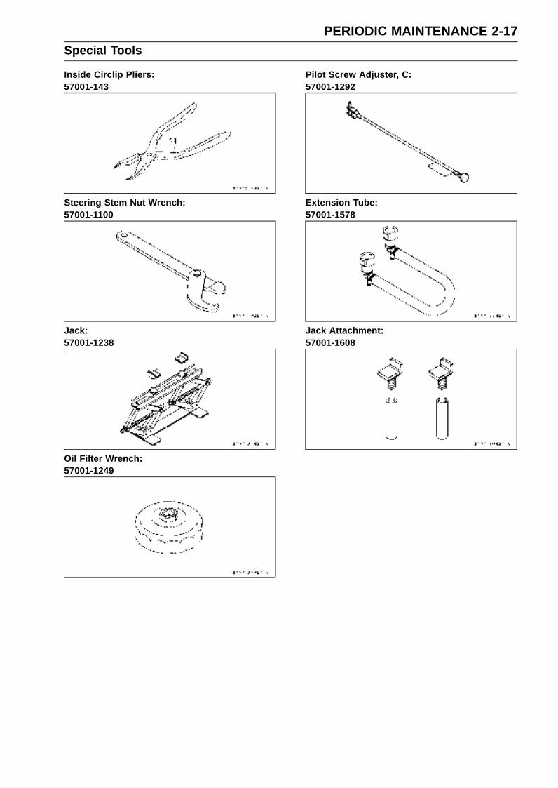
PERIODIC MAINTENANCE 2-17Special Tools
Inside Circlip Pliers:57001-143
Steering Stem Nut Wrench:57001-1100
Jack:57001-1238
Oil Filter Wrench:57001-1249
Pilot Screw Adjuster, C:57001-1292
Extension Tube:57001-1578
Jack Attachment:57001-1608
2-18 PERIODIC MAINTENANCEMaintenance Procedure
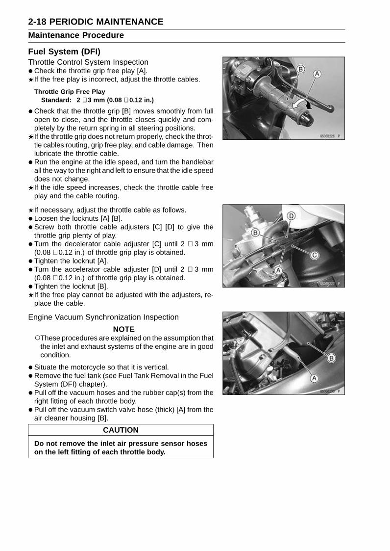
Fuel System (DFI)Throttle Control System Inspection•Check the throttle grip free play [A].
If the free play is incorrect, adjust the throttle cables.
Throttle Grip Free PlayStandard: 2 ∼ 3 mm (0.08 ∼ 0.12 in.)
•Check that the throttle grip [B] moves smoothly from fullopen to close, and the throttle closes quickly and com-pletely by the return spring in all steering positions.If the throttle grip does not return properly, check the throt-tle cables routing, grip free play, and cable damage. Thenlubricate the throttle cable.
•Run the engine at the idle speed, and turn the handlebarall the way to the right and left to ensure that the idle speeddoes not change.If the idle speed increases, check the throttle cable freeplay and the cable routing.
If necessary, adjust the throttle cable as follows.
• Loosen the locknuts [A] [B].
• Screw both throttle cable adjusters [C] [D] to give thethrottle grip plenty of play.
• Turn the decelerator cable adjuster [C] until 2 ∼ 3 mm(0.08 ∼ 0.12 in.) of throttle grip play is obtained.
• Tighten the locknut [A].
• Turn the accelerator cable adjuster [D] until 2 ∼ 3 mm(0.08 ∼ 0.12 in.) of throttle grip play is obtained.
• Tighten the locknut [B].If the free play cannot be adjusted with the adjusters, re-place the cable.
Engine Vacuum Synchronization Inspection
NOTEThese procedures are explained on the assumption that
the inlet and exhaust systems of the engine are in goodcondition.
•Situate the motorcycle so that it is vertical.
• Remove the fuel tank (see Fuel Tank Removal in the FuelSystem (DFI) chapter).
• Pull off the vacuum hoses and the rubber cap(s) from theright fitting of each throttle body.
• Pull off the vacuum switch valve hose (thick) [A] from theair cleaner housing [B].
CAUTION
Do not remove the inlet air pressure sensor hoseson the left fitting of each throttle body.
PERIODIC MAINTENANCE 2-19Maintenance Procedure
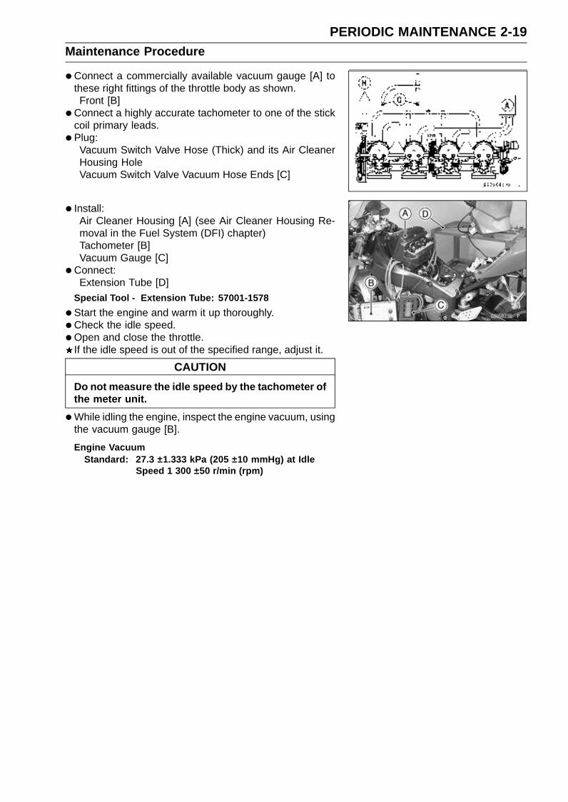
•Connect a commercially available vacuum gauge [A] tothese right fittings of the throttle body as shown.Front [B]
•Connect a highly accurate tachometer to one of the stickcoil primary leads.
• Plug:Vacuum Switch Valve Hose (Thick) and its Air CleanerHousing HoleVacuum Switch Valve Vacuum Hose Ends [C]
• Install:Air Cleaner Housing [A] (see Air Cleaner Housing Re-moval in the Fuel System (DFI) chapter)Tachometer [B]Vacuum Gauge [C]
•Connect:Extension Tube [D]
Special Tool - Extension Tube: 57001-1578
•Start the engine and warm it up thoroughly.
•Check the idle speed.
•Open and close the throttle.If the idle speed is out of the specified range, adjust it.
CAUTION
Do not measure the idle speed by the tachometer ofthe meter unit.
•While idling the engine, inspect the engine vacuum, usingthe vacuum gauge [B].
Engine VacuumStandard: 27.3 ±1.333 kPa (205 ±10 mmHg) at Idle
Speed 1 300 ±50 r/min (rpm)

2-20 PERIODIC MAINTENANCEMaintenance Procedure
If any vacuum is not within the specifications, first syn-chronize the balance of the left (#1, #2) and right (#3, #4)assemblies.
Example:#1: 165 mmHg#2: 190 mmHg#3: 170 mmHg#4: 200 mmHg
•With the engine at the correct idle speed, equalize thelower vacuum of #3 and #4 (example 170 mmHg) to thelower vacuum of #1 and #2 (example 165 mmHg) by turn-ing the center adjusting screw [A].Special Tool - Pilot Screw Adjuster, C: 57001-1292
Front [B]
NOTEAfter adjustment, the final vacuum measurement be-
tween the lowest throttle valves may not be 165 mmHg(in this example). The goal is to have the lower two vac-uums between the left (#1 and #2) and right (#3 and #4)banks be the same.
•Open and close the throttle after each measurement andadjust the idle speed as necessary.
•Once the throttle valves have been synchronized, inspectthe main throttle sensor’s output voltage to ensure properoperation (procedure is at the end of this section).
If any one vacuum measurement is out of the standardmeasurement after left and right synchronization, turn inthe bypass screws [A] until it seats fully but not tightly.Front [B]
CAUTION
Do not over tighten them. They could be damaged,requiring replacement.
•Turn out the bypass screw of the higher vacuum between#1 and #2 to the lower vacuum.
• Turn out the bypass screw of the higher vacuum between#3 and #4 to the lower vacuum.
•Open and close the throttle valves after each measure-ment and adjust the idle speed as necessary.
• Inspect the vacuums as before.If all vacuums are within the specification, finish the en-gine vacuum synchronization.If any vacuum can not be adjusted within the specification,remove the bypass screws #1 ∼ #4 and clean them.
PERIODIC MAINTENANCE 2-21Maintenance Procedure
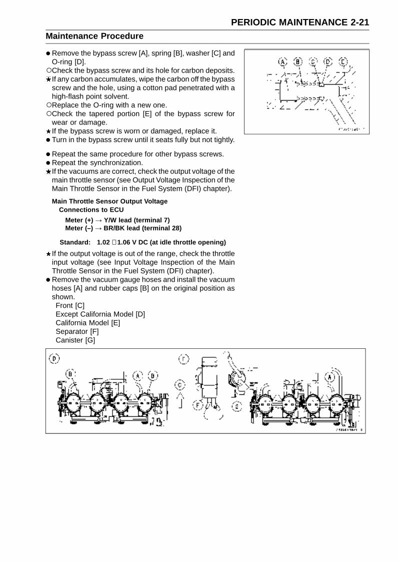
•Remove the bypass screw [A], spring [B], washer [C] andO-ring [D].Check the bypass screw and its hole for carbon deposits.
If any carbon accumulates, wipe the carbon off the bypassscrew and the hole, using a cotton pad penetrated with ahigh-flash point solvent.Replace the O-ring with a new one.Check the tapered portion [E] of the bypass screw for
wear or damage.If the bypass screw is worn or damaged, replace it.
• Turn in the bypass screw until it seats fully but not tightly.
• Repeat the same procedure for other bypass screws.
•Repeat the synchronization.If the vacuums are correct, check the output voltage of themain throttle sensor (see Output Voltage Inspection of theMain Throttle Sensor in the Fuel System (DFI) chapter).
Main Throttle Sensor Output VoltageConnections to ECU
Meter (+) → Y/W lead (terminal 7)Meter (–) → BR/BK lead (terminal 28)
Standard: 1.02 ∼ 1.06 V DC (at idle throttle opening)
If the output voltage is out of the range, check the throttleinput voltage (see Input Voltage Inspection of the MainThrottle Sensor in the Fuel System (DFI) chapter).
• Remove the vacuum gauge hoses and install the vacuumhoses [A] and rubber caps [B] on the original position asshown.Front [C]Except California Model [D]California Model [E]Separator [F]Canister [G]
2-22 PERIODIC MAINTENANCEMaintenance Procedure
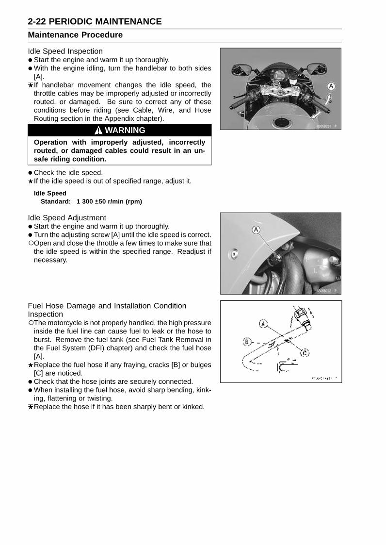
Idle Speed Inspection•Start the engine and warm it up thoroughly.
•With the engine idling, turn the handlebar to both sides[A].If handlebar movement changes the idle speed, thethrottle cables may be improperly adjusted or incorrectlyrouted, or damaged. Be sure to correct any of theseconditions before riding (see Cable, Wire, and HoseRouting section in the Appendix chapter).
WARNINGOperation with improperly adjusted, incorrectlyrouted, or damaged cables could result in an un-safe riding condition.
•Check the idle speed.If the idle speed is out of specified range, adjust it.
Idle SpeedStandard: 1 300 ±50 r/min (rpm)
Idle Speed Adjustment•Start the engine and warm it up thoroughly.
• Turn the adjusting screw [A] until the idle speed is correct.Open and close the throttle a few times to make sure that
the idle speed is within the specified range. Readjust ifnecessary.
Fuel Hose Damage and Installation ConditionInspectionThe motorcycle is not properly handled, the high pressure
inside the fuel line can cause fuel to leak or the hose toburst. Remove the fuel tank (see Fuel Tank Removal inthe Fuel System (DFI) chapter) and check the fuel hose[A].Replace the fuel hose if any fraying, cracks [B] or bulges[C] are noticed.
•Check that the hose joints are securely connected.
•When installing the fuel hose, avoid sharp bending, kink-ing, flattening or twisting.Replace the hose if it has been sharply bent or kinked.
PERIODIC MAINTENANCE 2-23Maintenance Procedure
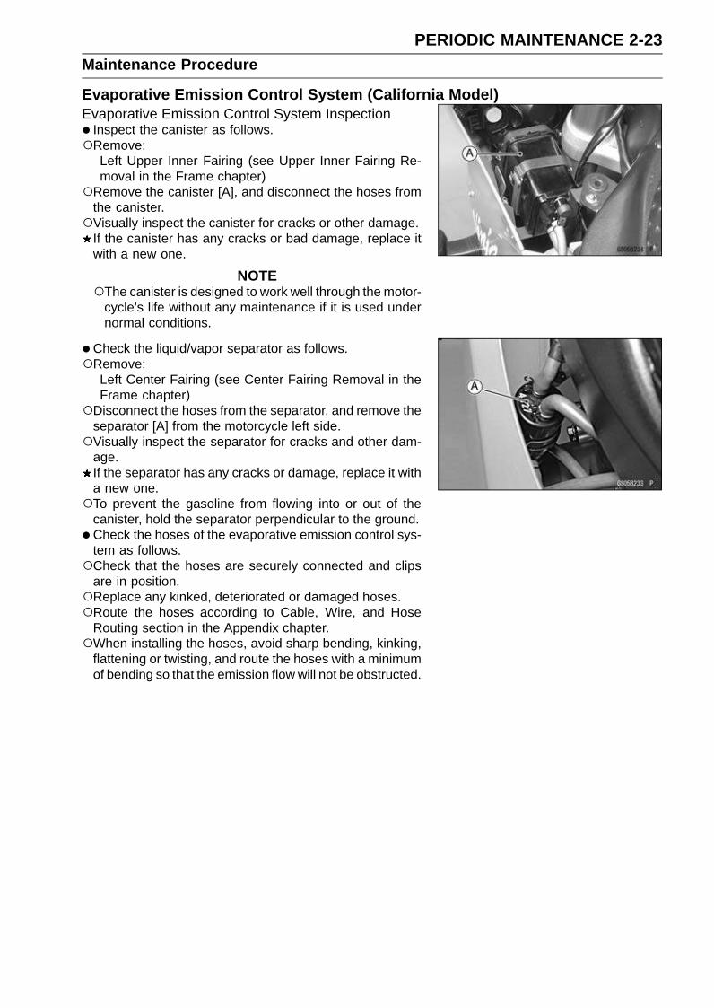
Evaporative Emission Control System (California Model)Evaporative Emission Control System Inspection• Inspect the canister as follows.Remove:
Left Upper Inner Fairing (see Upper Inner Fairing Re-moval in the Frame chapter)
Remove the canister [A], and disconnect the hoses fromthe canister.Visually inspect the canister for cracks or other damage.
If the canister has any cracks or bad damage, replace itwith a new one.
NOTEThe canister is designed to work well through the motor-
cycle’s life without any maintenance if it is used undernormal conditions.
•Check the liquid/vapor separator as follows.Remove:
Left Center Fairing (see Center Fairing Removal in theFrame chapter)
Disconnect the hoses from the separator, and remove theseparator [A] from the motorcycle left side.Visually inspect the separator for cracks and other dam-
age.If the separator has any cracks or damage, replace it witha new one.To prevent the gasoline from flowing into or out of the
canister, hold the separator perpendicular to the ground.
•Check the hoses of the evaporative emission control sys-tem as follows.Check that the hoses are securely connected and clips
are in position.Replace any kinked, deteriorated or damaged hoses.Route the hoses according to Cable, Wire, and Hose
Routing section in the Appendix chapter.When installing the hoses, avoid sharp bending, kinking,
flattening or twisting, and route the hoses with a minimumof bending so that the emission flow will not be obstructed.

2-24 PERIODIC MAINTENANCEMaintenance Procedure
Cooling SystemCoolant Level Inspection
NOTECheck the level when the engine is cold (room or ambi-
ent temperature).
•Check the coolant level in the reserve tank [A] withthe motorcycle held perpendicular (Do not use the sidestand).If the coolant level is lower than the “L” level line [B], un-screw the reserve tank cap and add coolant to the “F”level line [C].“L”: low“F”: full
CAUTION
For refilling, add the specified mixture of coolantand soft water. Adding water alone dilutes thecoolant and degrades its anticorrosion properties.The diluted coolant can attack the aluminum en-gine parts. In an emergency, soft water alone canbe added. But the diluted coolant must be returnedto the correct mixture ratio within a few days.If coolant must be added often or the reservoir tankhas run completely dry, there is probably leakage inthe cooling system. Check the system for leaks.Coolant ruins painted surfaces. Immediately washaway any coolant that spills on the frame, engine,wheels or other painted parts.
Radiator Hose Damage and Installation ConditionInspectionThe high pressure inside the radiator hose can cause
coolant to leak [A] or the hose to burst if the line is notproperly maintained. Visually inspect the hoses for signsof deterioration. Squeeze the hoses. A hose should notbe hard and brittle, nor should it be soft or swollen.Replace the hose if any fraying, cracks [B] or bulges [C]are noticed.
•Check that the hoses are securely connected and clampsare tightened correctly.Torque - Radiator Hose Clamp Screws: 2.0 N·m (0.20 kgf·m,
17 in·lb)
PERIODIC MAINTENANCE 2-25Maintenance Procedure
Engine Top EndValve Clearance Inspection
NOTEValve clearance must be checked and adjusted when
the engine is cold (at room temperature).
•Remove:Lower Fairings (see Lower Fairing Removal in the Framechapter)Crankshaft Sensor Cover (see Crankshaft Sensor Re-moval in the Electrical System chapter)Cylinder Head Cover (see Cylinder Head Cover Re-moval in the Engine Top End chapter)
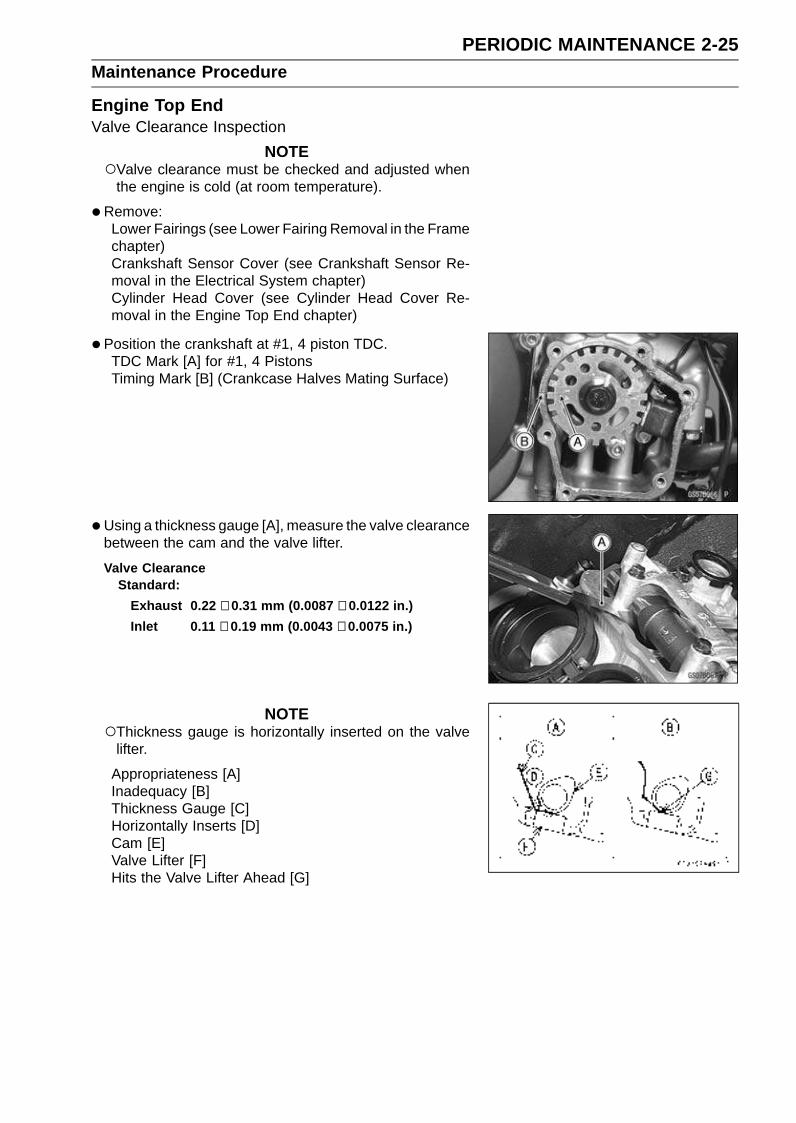
• Position the crankshaft at #1, 4 piston TDC.TDC Mark [A] for #1, 4 PistonsTiming Mark [B] (Crankcase Halves Mating Surface)
•Using a thickness gauge [A], measure the valve clearancebetween the cam and the valve lifter.
Valve ClearanceStandard:
Exhaust 0.22 ∼ 0.31 mm (0.0087 ∼ 0.0122 in.)
Inlet 0.11 ∼ 0.19 mm (0.0043 ∼ 0.0075 in.)
NOTEThickness gauge is horizontally inserted on the valve
lifter.
Appropriateness [A]Inadequacy [B]Thickness Gauge [C]Horizontally Inserts [D]Cam [E]Valve Lifter [F]Hits the Valve Lifter Ahead [G]
2-26 PERIODIC MAINTENANCEMaintenance Procedure
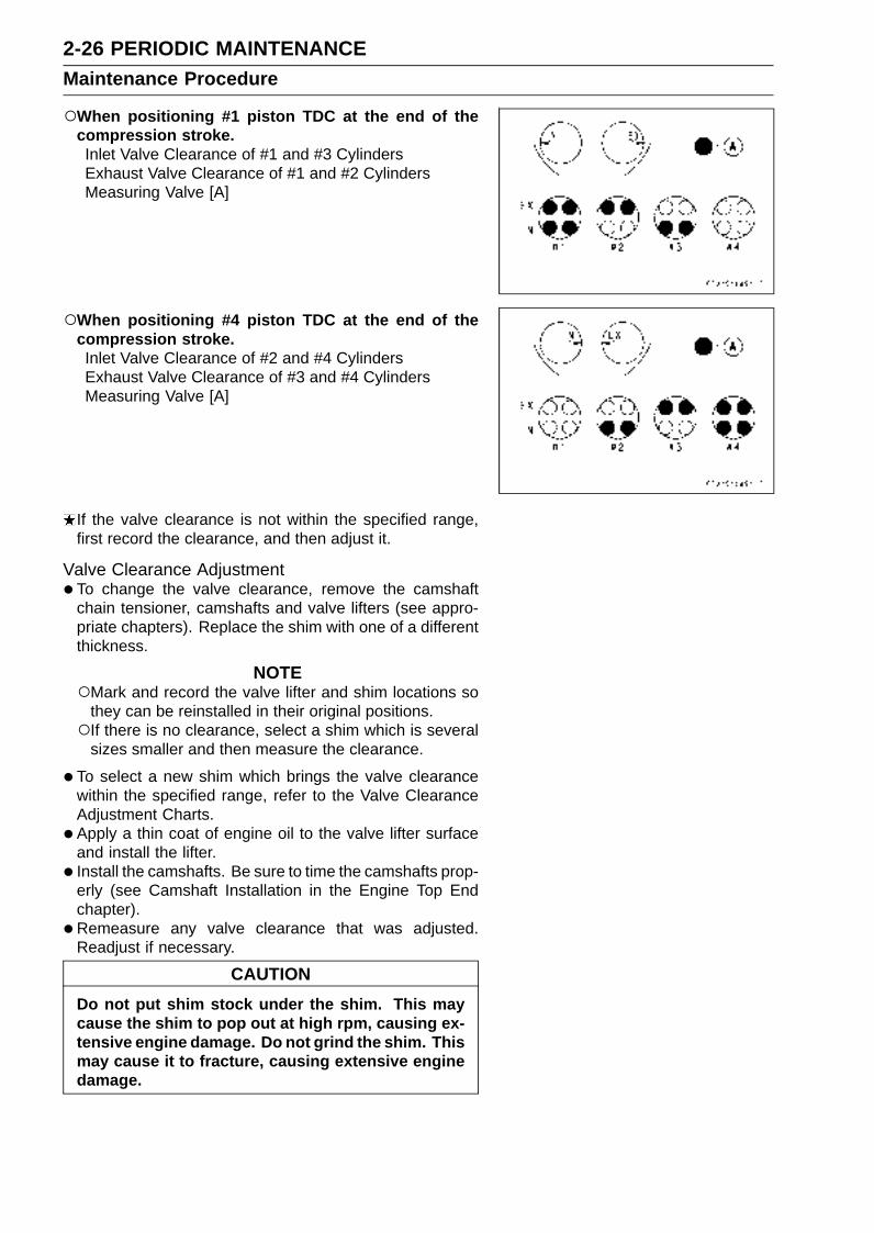
When positioning #1 piston TDC at the end of thecompression stroke.Inlet Valve Clearance of #1 and #3 CylindersExhaust Valve Clearance of #1 and #2 CylindersMeasuring Valve [A]
When positioning #4 piston TDC at the end of thecompression stroke.Inlet Valve Clearance of #2 and #4 CylindersExhaust Valve Clearance of #3 and #4 CylindersMeasuring Valve [A]
If the valve clearance is not within the specified range,first record the clearance, and then adjust it.
Valve Clearance Adjustment•To change the valve clearance, remove the camshaft
chain tensioner, camshafts and valve lifters (see appro-priate chapters). Replace the shim with one of a differentthickness.
NOTEMark and record the valve lifter and shim locations so
they can be reinstalled in their original positions.If there is no clearance, select a shim which is several
sizes smaller and then measure the clearance.
•To select a new shim which brings the valve clearancewithin the specified range, refer to the Valve ClearanceAdjustment Charts.
• Apply a thin coat of engine oil to the valve lifter surfaceand install the lifter.
• Install the camshafts. Be sure to time the camshafts prop-erly (see Camshaft Installation in the Engine Top Endchapter).
• Remeasure any valve clearance that was adjusted.Readjust if necessary.
CAUTION
Do not put shim stock under the shim. This maycause the shim to pop out at high rpm, causing ex-tensive engine damage. Do not grind the shim. Thismay cause it to fracture, causing extensive enginedamage.
PERIODIC MAINTENANCE 2-27Maintenance Procedure
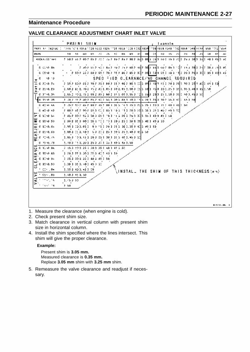
VALVE CLEARANCE ADJUSTMENT CHART INLET VALVE
1. Measure the clearance (when engine is cold).2. Check present shim size.3. Match clearance in vertical column with present shim
size in horizontal column.4. Install the shim specified where the lines intersect. This
shim will give the proper clearance.
Example:
Present shim is 3.05 mm.Measured clearance is 0.35 mm.Replace 3.05 mm shim with 3.25 mm shim.
5. Remeasure the valve clearance and readjust if neces-sary.
2-28 PERIODIC MAINTENANCEMaintenance Procedure
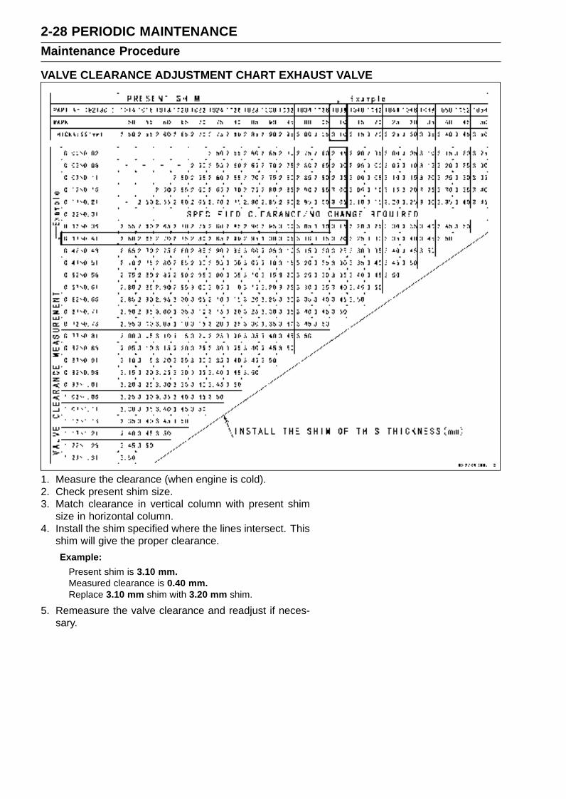
VALVE CLEARANCE ADJUSTMENT CHART EXHAUST VALVE
1. Measure the clearance (when engine is cold).2. Check present shim size.3. Match clearance in vertical column with present shim
size in horizontal column.4. Install the shim specified where the lines intersect. This
shim will give the proper clearance.
Example:
Present shim is 3.10 mm.Measured clearance is 0.40 mm.Replace 3.10 mm shim with 3.20 mm shim.
5. Remeasure the valve clearance and readjust if neces-sary.
PERIODIC MAINTENANCE 2-29Maintenance Procedure
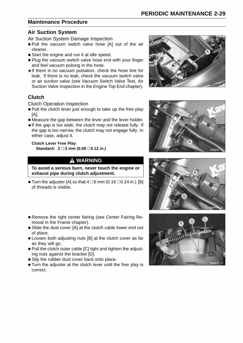
Air Suction SystemAir Suction System Damage Inspection•Pull the vacuum switch valve hose [A] out of the air
cleaner.
• Start the engine and run it at idle speed.
• Plug the vacuum switch valve hose end with your fingerand feel vacuum pulsing in the hose.If there is no vacuum pulsation, check the hose line forleak. If there is no leak, check the vacuum switch valveor air suction valve (see Vacuum Switch Valve Test, AirSuction Valve Inspection in the Engine Top End chapter).
ClutchClutch Operation Inspection•Pull the clutch lever just enough to take up the free play
[A].
•Measure the gap between the lever and the lever holder.If the gap is too wide, the clutch may not release fully. Ifthe gap is too narrow, the clutch may not engage fully. Ineither case, adjust it.
Clutch Lever Free PlayStandard: 2 ∼ 3 mm (0.08 ∼ 0.12 in.)
WARNINGTo avoid a serious burn, never touch the engine orexhaust pipe during clutch adjustment.
•Turn the adjuster [A] so that 4 ∼ 6 mm (0.16 ∼ 0.24 in.) [B]of threads is visible.
•Remove the right center fairing (see Center Fairing Re-moval in the Frame chapter).
• Slide the dust cover [A] at the clutch cable lower end outof place.
• Loosen both adjusting nuts [B] at the clutch cover as faras they will go.
• Pull the clutch outer cable [C] tight and tighten the adjust-ing nuts against the bracket [D].
• Slip the rubber dust cover back onto place.
• Turn the adjuster at the clutch lever until the free play iscorrect.

2-30 PERIODIC MAINTENANCEMaintenance Procedure
•Push the release lever [A] toward the front of the motor-cycle until it becomes hard to turn.At this time, the release lever should have the proper an-
gle shown.60° [B]
If the angle is wrong, check the clutch and release partsfor wear.
WARNINGBe sure that the outer cable end at the clutch leveris fully seated in the adjuster at the clutch lever, orit could slip into place later, creating enough cableplay to prevent clutch disengagement.
•After the adjustment, start the engine and check that theclutch does not slip and that it releases properly.
Wheels/TiresAir Pressure Inspection•Measure the tire air pressure with an air pressure gauge
[A] when the tires are cold (that is, when the motorcyclehas not been ridden more than a mile during the past 3hours).
• Install the air valve cap.Adjust the tire air pressure according to the specificationsif necessary.
Air Pressure (when Cold)Front: Up to 180 kg (397 lb)
250 kPa (2.5 kgf/cm², 36 psi)
Rear: Up to 180 kg (397 lb)
290 kPa (2.9 kgf/cm², 42 psi)
Wheel/Tire Damage Inspection•Remove any imbedded stones [A] or other foreign parti-
cles [B] from tread.
• Visually inspect the tire for cracks and cuts, and replacethe tire if necessary. Swelling or high spots indicate inter-nal damage, requiring tire replacement.
• Visually inspect the wheel for cracks, cuts and dents dam-age.If any damage is found, replace the wheel if necessary.
Tire Tread Wear InspectionAs the tire tread wears down, the tire becomes more sus-
ceptible to puncture and failure. An accepted estimate isthat 90% of all tire failures occur during the last 10% of treadlife (90% worn). So it is false economy and unsafe to usethe tires until they are bald.
•Measure the tread depth at the center of the tread with adepth gauge [A]. Since the tire may wear unevenly, takemeasurement at several places.If any measurement is less than the service limit, replacethe tire (see Tire Removal/Installation in the Wheels/Tireschapter).

PERIODIC MAINTENANCE 2-31Maintenance Procedure
Tread DepthStandard:
Front 3.6 mm (0.14 in.)
Rear 5.8 mm (0.23 in.)
Service Limit:
Front 1 mm (0.04 in.)
(AT, CH, DE) 1.6 mm (0.06 in.)
Rear 2 mm (0.08 in.) (Up to 130 km/h)
3 mm (0.12 in.) (Over 130 km/h)
WARNINGTo ensure safe handling and stability, use only therecommended standard tires for replacement, in-flated to the standard pressure.
NOTEMost countries may have their own regulations a mini-
mum tire tread depth: be sure to follow them.Check and balance the wheel when a tire is replaced
with a new one.
Wheel Bearing Damage Inspection•Using a jack and attachment, raise the front wheel off the
ground (see Front Wheel Removal in the Wheels/Tireschapter).
• Turn the handlebar all the way to the right or left.
• Inspect the roughness of the front wheel bearing by push-ing and pulling [A] the wheel.
• Spin [B] the front wheel lightly, and check for smoothlyturn, roughness, binding or noise.If roughness, binding or noise is found, remove the frontwheel and inspect the wheel bearing (see Front WheelRemoval, Hub Bearing Inspection in the Wheels/Tireschapter).
• Using a stand, raise the rear wheel off the ground (seeRear Wheel Removal in the Wheels/Tires chapter).
• Inspect the roughness of the rear wheel bearing by push-ing and pulling [A] the wheel.
• Spin [B] the rear wheel lightly, and check for smoothlyturn, roughness, binding or noise.If roughness, binding or noise is found, remove the rearwheel and inspect the wheel bearing (see Rear Wheel Re-moval, Hub Bearing Inspection in the Wheels/Tires chap-ter) and coupling (see Coupling Bearing Inspection in theFinal Drive chapter).

2-32 PERIODIC MAINTENANCEMaintenance Procedure
Drive TrainDrive Chain Lubrication Condition Inspection• If a special lubricant is not available, a heavy oil such as
SAE 90 is preferred to a lighter oil because it will stay onthe chain longer and provide better lubrication.
• If the chain appears especially dirty, clean it before lubri-cation.
CAUTION
The O-rings between the side plates seal in the lu-bricant between the pin and the bushing. To avoiddamaging the O-rings and resultant loss of lubri-cant, observe the following rules.Use only kerosene or diesel oil for cleaning of theO-ring of the drive chain.Any other cleaning solution such as gasolineor trichloroethylene will cause deterioration andswelling of the O-ring.Immediately blow the chain dry with compressed airafter cleaning.Complete cleaning and drying the chain within 10minutes.
•Apply oil to the sides of the rollers so that oil will penetrateto the rollers and bushings. Apply the oil to the O-rings sothat the O-rings will be coated with oil.
•Wipe off any excess oil.Oil Applied Areas [A]O-ring [B]
Drive Chain Slack Inspection
NOTECheck the slack with the motorcycle setting on its side
stand.Clean the chain if it is dirty, and lubricate it if it appears
dry.
•Check the wheel alignment (see Wheel Alignment Inspec-tion in this chapter).
• Rotate the rear wheel to find the position where the chainis tightest.
•Measure the vertical movement (chain slack) [A] midwaybetween the sprockets.If the chain slack exceeds the standard, adjust it.
Chain SlackStandard: 30 ∼ 35 mm (1.2 ∼ 1.4 in.)
PERIODIC MAINTENANCE 2-33Maintenance Procedure
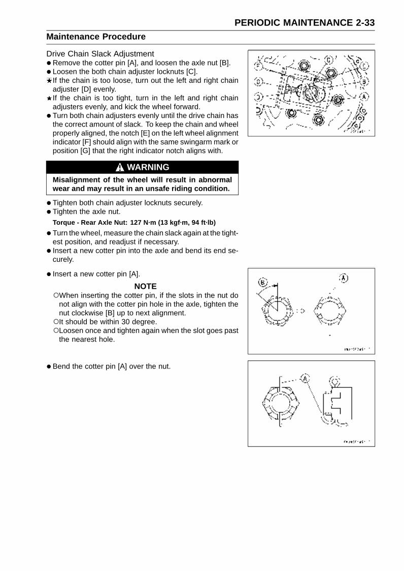
Drive Chain Slack Adjustment•Remove the cotter pin [A], and loosen the axle nut [B].
• Loosen the both chain adjuster locknuts [C].If the chain is too loose, turn out the left and right chainadjuster [D] evenly.If the chain is too tight, turn in the left and right chainadjusters evenly, and kick the wheel forward.
• Turn both chain adjusters evenly until the drive chain hasthe correct amount of slack. To keep the chain and wheelproperly aligned, the notch [E] on the left wheel alignmentindicator [F] should align with the same swingarm mark orposition [G] that the right indicator notch aligns with.
WARNINGMisalignment of the wheel will result in abnormalwear and may result in an unsafe riding condition.
•Tighten both chain adjuster locknuts securely.
• Tighten the axle nut.Torque - Rear Axle Nut: 127 N·m (13 kgf·m, 94 ft·lb)
•Turn the wheel, measure the chain slack again at the tight-est position, and readjust if necessary.
• Insert a new cotter pin into the axle and bend its end se-curely.
• Insert a new cotter pin [A].
NOTEWhen inserting the cotter pin, if the slots in the nut do
not align with the cotter pin hole in the axle, tighten thenut clockwise [B] up to next alignment.It should be within 30 degree.Loosen once and tighten again when the slot goes past
the nearest hole.
•Bend the cotter pin [A] over the nut.
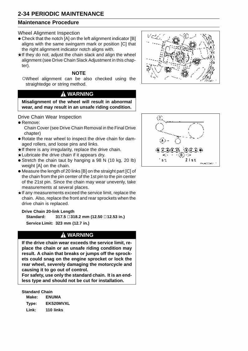
2-34 PERIODIC MAINTENANCEMaintenance Procedure
Wheel Alignment Inspection•Check that the notch [A] on the left alignment indicator [B]
aligns with the same swingarm mark or position [C] thatthe right alignment indicator notch aligns with.If they do not, adjust the chain slack and align the wheelalignment (see Drive Chain Slack Adjustment in this chap-ter).
NOTEWheel alignment can be also checked using the
straightedge or string method.
WARNINGMisalignment of the wheel will result in abnormalwear, and may result in an unsafe riding condition.
Drive Chain Wear Inspection•Remove:
Chain Cover (see Drive Chain Removal in the Final Drivechapter)
•Rotate the rear wheel to inspect the drive chain for dam-aged rollers, and loose pins and links.If there is any irregularity, replace the drive chain.Lubricate the drive chain if it appears dry.
• Stretch the chain taut by hanging a 98 N (10 kg, 20 lb)weight [A] on the chain.
•Measure the length of 20 links [B] on the straight part [C] ofthe chain from the pin center of the 1st pin to the pin centerof the 21st pin. Since the chain may wear unevenly, takemeasurements at several places.If any measurements exceed the service limit, replace thechain. Also, replace the front and rear sprockets when thedrive chain is replaced.
Drive Chain 20-link LengthStandard: 317.5 ∼ 318.2 mm (12.50 ∼ 12.53 in.)
Service Limit: 323 mm (12.7 in.)
WARNINGIf the drive chain wear exceeds the service limit, re-place the chain or an unsafe riding condition mayresult. A chain that breaks or jumps off the sprock-ets could snag on the engine sprocket or lock therear wheel, severely damaging the motorcycle andcausing it to go out of control.For safety, use only the standard chain. It is an end-less type and should not be cut for installation.
Standard ChainMake: ENUMA
Type: EK520MVXL
Link: 110 links

PERIODIC MAINTENANCE 2-35Maintenance Procedure
Chain Guide Wear Inspection•Remove:
Swingarm (see Swingarm Removal in the Suspensionchapter)
• Visually inspect the chain guide [A].Replace the chain guide if it shows any signs of abnormalwear or damage.
Brake SystemBrake Fluid Leak (Brake Hose and Pipe) Inspection•Apply the brake lever or pedal and inspect the brake fluid
leak from the brake hoses [A] and fittings.If the brake fluid leaked from any position, inspect or re-place the problem part.
Brake Hose Damage and Installation ConditionInspection• Inspect the brake hoses and fittings for deterioration,
cracks and signs of leakage.The high pressure inside the brake line can cause fluid to
leak [A] or the hose to burst if the line is not properly main-tained. Bend and twist the rubber hose while examiningit.Replace the hose if any crack [B], bulge [C] or leakage isnoticed.Tighten any brake hose banjo bolts.
Torque - Brake Hose Banjo Bolts: 25 N·m (2.5 kgf·m, 18ft·lb)
• Inspect the brake hose routing.If any brake hose routing is incorrect, route the brake hoseaccording to Cable, Wire, and Hose Routing section in theAppendix chapter.
Brake Operation Inspection• Inspect the operation of the front and rear brake by run-
ning the vehicle on the dry road.If the brake operation is insufficiency, inspect the brakesystem.
WARNINGWhen inspecting by running the vehicle, note asurrounding traffic situation enough in the place ofsafety.

2-36 PERIODIC MAINTENANCEMaintenance Procedure
Brake Fluid Level Inspection•Check that the brake fluid level in the front brake reservoir
[A] is above the lower level line [B].
NOTEHold the reservoir horizontal by turning the handlebar
when checking brake fluid level.
If the fluid level is lower than the lower level line, fill thereservoir to the upper level line [C].
• Check that the brake fluid level in the rear brake reservoir[A] is above the lower level [B].If the fluid level is lower than the lower level line, fill thereservoir to the upper level line [C].
WARNINGChange the brake fluid in the brake line completelyif the brake fluid must be refilled but the type andbrand of the brake fluid that is already in the reser-voir are unidentified. After changing the fluid, useonly the same type and brand of fluid thereafter.
Recommended Disc Brake FluidGrade: DOT4
Brake Pad Wear Inspection•Remove the brake pads (see Front/Rear Brake Pad Re-
moval in the Brakes chapter).
• Check the lining thickness [A] of the pads in each caliper.If the lining thickness of either pad is less than the servicelimit [B], replace both pads in the caliper as a set.
Pad Lining ThicknessStandard:
Front 4.0 mm (0.16 in.)
Rear 5.0 mm (0.20 in.)
Service Limit: 1 mm (0.04 in.)
Brake Light Switch Operation Inspection•Turn on the ignition switch.
• The brake light [A] should go on when the brake lever isapplied or after the brake pedal is depressed about 10mm (0.39 in.).
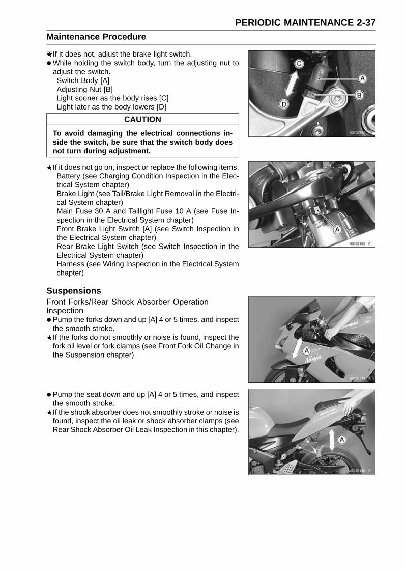
PERIODIC MAINTENANCE 2-37Maintenance Procedure
If it does not, adjust the brake light switch.
•While holding the switch body, turn the adjusting nut toadjust the switch.Switch Body [A]Adjusting Nut [B]Light sooner as the body rises [C]Light later as the body lowers [D]
CAUTION
To avoid damaging the electrical connections in-side the switch, be sure that the switch body doesnot turn during adjustment.
If it does not go on, inspect or replace the following items.Battery (see Charging Condition Inspection in the Elec-trical System chapter)Brake Light (see Tail/Brake Light Removal in the Electri-cal System chapter)Main Fuse 30 A and Taillight Fuse 10 A (see Fuse In-spection in the Electrical System chapter)Front Brake Light Switch [A] (see Switch Inspection inthe Electrical System chapter)Rear Brake Light Switch (see Switch Inspection in theElectrical System chapter)Harness (see Wiring Inspection in the Electrical Systemchapter)
SuspensionsFront Forks/Rear Shock Absorber OperationInspection•Pump the forks down and up [A] 4 or 5 times, and inspect
the smooth stroke.If the forks do not smoothly or noise is found, inspect thefork oil level or fork clamps (see Front Fork Oil Change inthe Suspension chapter).
• Pump the seat down and up [A] 4 or 5 times, and inspectthe smooth stroke.If the shock absorber does not smoothly stroke or noise isfound, inspect the oil leak or shock absorber clamps (seeRear Shock Absorber Oil Leak Inspection in this chapter).
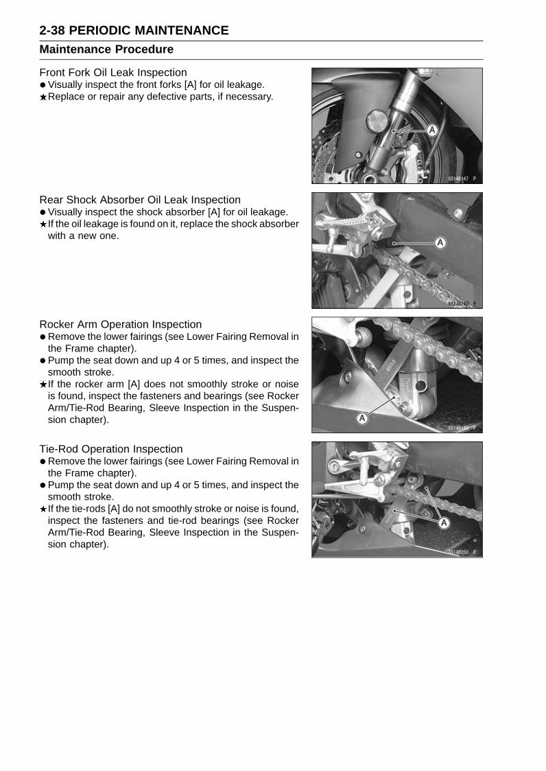
2-38 PERIODIC MAINTENANCEMaintenance Procedure
Front Fork Oil Leak Inspection•Visually inspect the front forks [A] for oil leakage.
Replace or repair any defective parts, if necessary.
Rear Shock Absorber Oil Leak Inspection•Visually inspect the shock absorber [A] for oil leakage.
If the oil leakage is found on it, replace the shock absorberwith a new one.
Rocker Arm Operation Inspection•Remove the lower fairings (see Lower Fairing Removal in
the Frame chapter).
• Pump the seat down and up 4 or 5 times, and inspect thesmooth stroke.If the rocker arm [A] does not smoothly stroke or noiseis found, inspect the fasteners and bearings (see RockerArm/Tie-Rod Bearing, Sleeve Inspection in the Suspen-sion chapter).
Tie-Rod Operation Inspection•Remove the lower fairings (see Lower Fairing Removal in
the Frame chapter).
• Pump the seat down and up 4 or 5 times, and inspect thesmooth stroke.If the tie-rods [A] do not smoothly stroke or noise is found,inspect the fasteners and tie-rod bearings (see RockerArm/Tie-Rod Bearing, Sleeve Inspection in the Suspen-sion chapter).

PERIODIC MAINTENANCE 2-39Maintenance Procedure
Steering SystemSteering Play Inspection•Remove the lower fairings (see Lower Fairing Removal in
the Frame chapter).
• Lift the front wheel off the ground using the jack.Special Tools - Jack: 57001-1238
Jack Attachment: 57001-1608
•With the front wheel pointing straight ahead, alternatelytap each end of the handlebar. The front wheel shouldswing fully left and right from the force of gravity until thefork hits the stop.If the wheel binds or catches before the stop, the steeringis too tight.
• Feel for steering looseness by pushing and pulling theforks.If you feel looseness, the steering is too loose.
NOTEThe cables and wiring will have some effect on the mo-
tion of the fork which must be taken into account.Be sure the wires and cables are properly routed.The bearings must be in good condition and properly
lubricated in order for any test to be valid.
Steering Play Adjustment•Remove:
Stem Head Nut [A] and Washer [B]
• Loosen the upper fork clamp bolts [C] and handlebar bolts[D].
• Remove the stem head [E] with handlebar.
• Bend the claw washer tabs [A].
• Remove the steering stem locknut [B] and claw washer[C].
• Adjust the steering.Special Tool - Steering Stem Nut Wrench: 57001-1100
If the steering is too tight, loosen the stem nut a fractionof a turn.If the steering is too loose, tighten the stem nut a fractionof a turn.
NOTETurn the stem nut 1/8 turn at time maximum.
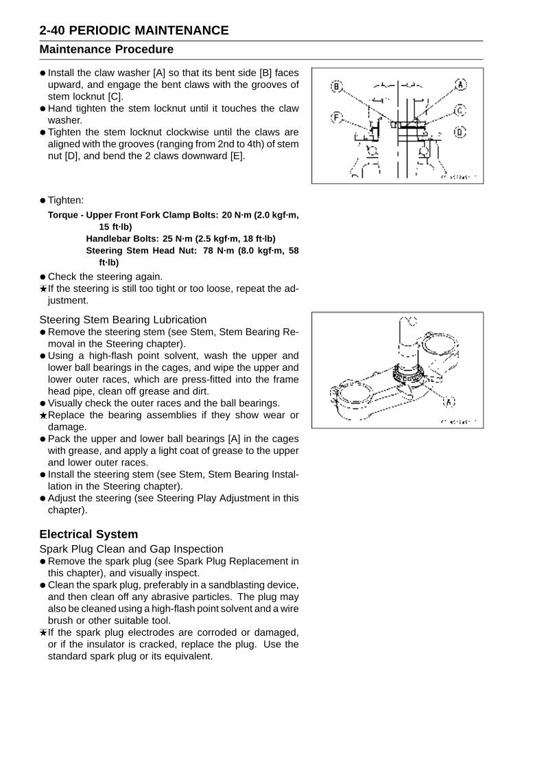
2-40 PERIODIC MAINTENANCEMaintenance Procedure
• Install the claw washer [A] so that its bent side [B] facesupward, and engage the bent claws with the grooves ofstem locknut [C].
• Hand tighten the stem locknut until it touches the clawwasher.
• Tighten the stem locknut clockwise until the claws arealigned with the grooves (ranging from 2nd to 4th) of stemnut [D], and bend the 2 claws downward [E].
• Tighten:Torque - Upper Front Fork Clamp Bolts: 20 N·m (2.0 kgf·m,
15 ft·lb)Handlebar Bolts: 25 N·m (2.5 kgf·m, 18 ft·lb)Steering Stem Head Nut: 78 N·m (8.0 kgf·m, 58
ft·lb)
•Check the steering again.If the steering is still too tight or too loose, repeat the ad-justment.
Steering Stem Bearing Lubrication•Remove the steering stem (see Stem, Stem Bearing Re-
moval in the Steering chapter).
• Using a high-flash point solvent, wash the upper andlower ball bearings in the cages, and wipe the upper andlower outer races, which are press-fitted into the framehead pipe, clean off grease and dirt.
• Visually check the outer races and the ball bearings.Replace the bearing assemblies if they show wear ordamage.
• Pack the upper and lower ball bearings [A] in the cageswith grease, and apply a light coat of grease to the upperand lower outer races.
• Install the steering stem (see Stem, Stem Bearing Instal-lation in the Steering chapter).
• Adjust the steering (see Steering Play Adjustment in thischapter).
Electrical SystemSpark Plug Clean and Gap Inspection•Remove the spark plug (see Spark Plug Replacement in
this chapter), and visually inspect.
• Clean the spark plug, preferably in a sandblasting device,and then clean off any abrasive particles. The plug mayalso be cleaned using a high-flash point solvent and a wirebrush or other suitable tool.If the spark plug electrodes are corroded or damaged,or if the insulator is cracked, replace the plug. Use thestandard spark plug or its equivalent.

PERIODIC MAINTENANCE 2-41Maintenance Procedure
•Measure the gap [A] with a wire-type thickness gauge.If the gap is incorrect, carefully bend the side electrode[B] with a suitable tool to obtain the correct gap.
Spark Plug Gap : 0.7 ∼ 0.8 mm (0.028 ∼ 0.031 in.)
CAUTION
Use only the recommended spark plugs (specialmarks ). These spark plugs have special marks[C] on the insulator, as shown. Other spark plugswill wear prematurely.

2-42 PERIODIC MAINTENANCEMaintenance Procedure
Lights and Switches Operation InspectionFirst Step
•Turn on the ignition switch.
• The following lights should go on according to below table.
City Light [A] goes on
Taillight [B] goes on
License Plate Light [C] goes on
Meter Panel LCD [D] goes on
Neutral Indicator LED [E] goes on
Oil Pressure Warning Indicator LED [F] goes on
FI Indicator LED [G] goes on(about 2 seconds)
If the light does not go on, inspect or replace the followingitem.Battery (see Charging Condition Inspection in the Elec-trical System chapter)Applicable Bulb (see Wiring Diagram in the ElectricalSystem chapter)Meter Unit for Meter Panel LCD (see Electronic Combi-nation Meter Assembly Inspection in the Electrical Sys-tem chapter)Meter Unit for Neutral Indicator LED (see ElectronicCombination Meter Assembly Inspection in the Electri-cal System chapter)Meter Unit for Oil Pressure Warning Indicator LED (seeElectronic Combination Meter Assembly Inspection inthe Electrical System chapter)Meter Unit for FI Indicator LED (see Electronic Combina-tion Meter Assembly Inspection in the Electrical Systemchapter)ECU (see ECU Power Supply Inspection in the Fuel Sys-tem (DFI) chapter)Main Fuse 30 A and Taillight Fuse 10 A (see Fuse In-spection in the Electrical System chapter)Ignition Switch (see Switch Inspection in the ElectricalSystem chapter)Neutral Switch (see Switch Inspection in the ElectricalSystem chapter)Harness (see Wiring Inspection in the Electrical Systemchapter)
• Turn off the ignition switch.
• The all lights should go off (for the immobilizer model,FI indicator LED will blink. see Abstract in the ElectricalSystem chapter).If the light does not go off, replace the ignition switch.
Second Step
•Turn the ignition switch to P (Park) position.
• The city light, taillight and license plate light should go on.If the light does not go on, inspect or replace the followingitem.Ignition Switch (see Switch Inspection in the ElectricalSystem chapter)

PERIODIC MAINTENANCE 2-43Maintenance Procedure
Third Step
•Turn on the turn signal switch [A] (left or right position).
• The left or right turn signal lights [B] (front and rear) ac-cording to the switch position should flash.
• The turn signal indicator LED [C] in the meter unit shouldflash.If the each light does not flash, inspect or replace thefollowing item.Turn Signal Light Bulb (see Turn Signal Light Bulb Re-placement in the Electrical System chapter)Meter Unit for Turn Signal Light Indicator LED (see Elec-tronic Combination Meter Assembly Inspection in theElectrical System chapter)Turn Signal Relay Fuse 10 A (see Fuse Inspection in theElectrical System chapter)Turn Signal Switch (see Switch Inspection in the Electri-cal System chapter)Turn Signal Relay (see Turn Signal Relay Inspection inthe Electrical System chapter)Harness (see Wiring Inspection in the Electrical Systemchapter)
• Push the turn signal switch.
• The turn signal lights and indicator LED should go off.If the light does not go off, inspect or replace the followingitem.Turn Signal Switch (see Switch Inspection in the Electri-cal System chapter)Turn Signal Relay (see Turn Signal Relay Inspection inthe Electrical System chapter)
Fourth Step
•Set the dimmer switch [A] to low beam position.
• Start the engine.
• The low beam headlight should go on.If the low beam headlight does not go on, inspect or re-place the following item.Headlight Low Beam Bulb (see Headlight Bulb Replace-ment in the Electrical System chapter)Headlight Fuse 10 A (see Fuse Inspection in the Electri-cal System chapter)Dimmer Switch (see Switch Inspection in the ElectricalSystem chapter)Headlight Relay in Relay Box (see Relay Circuit Inspec-tion in the Electrical System chapter)Harness (see Wiring Inspection in the Electrical Systemchapter)

2-44 PERIODIC MAINTENANCEMaintenance Procedure
•Set the dimmer switch to high beam position.
• The low beam [A] and high beam [B] headlights shouldgo on.
• The high beam indicator LED [C] should go on.If the high beam headlight and/or high beam indicator LEDdoes not go on, inspect or replace the following item.Headlight High Beam Bulb (see Headlight Bulb Replace-ment in the Electrical System chapter)Dimmer Switch (see Switch Inspection in the ElectricalSystem chapter)
• Turn off the engine stop switch.
• The low beam and high beam headlights should stay go-ing on.If the headlights and high beam indicator LED does gooff, inspect or replace the following item.Headlight Relay in Relay Box (see Relay Circuit Inspec-tion in the Electrical System chapter)
• Turn off the ignition switch.
• The headlights and high beam indicator LED should gooff.
Headlight Aiming Inspection• Inspect the headlight beam for aiming.
If the headlight beam points to one side rather thanstraight ahead, adjust the horizontal beam.
Headlight Beam Horizontal Adjustment
•Turn the horizontal adjuster [A] in both headlights in or outuntil the beam points straight ahead.If the headlight beam points too low or high, adjust thevertical beam.
Headlight Beam Vertical Adjustment
•Turn the vertical adjuster [B] in both headlights in or outwith a screwdriver to adjust the headlight vertically.
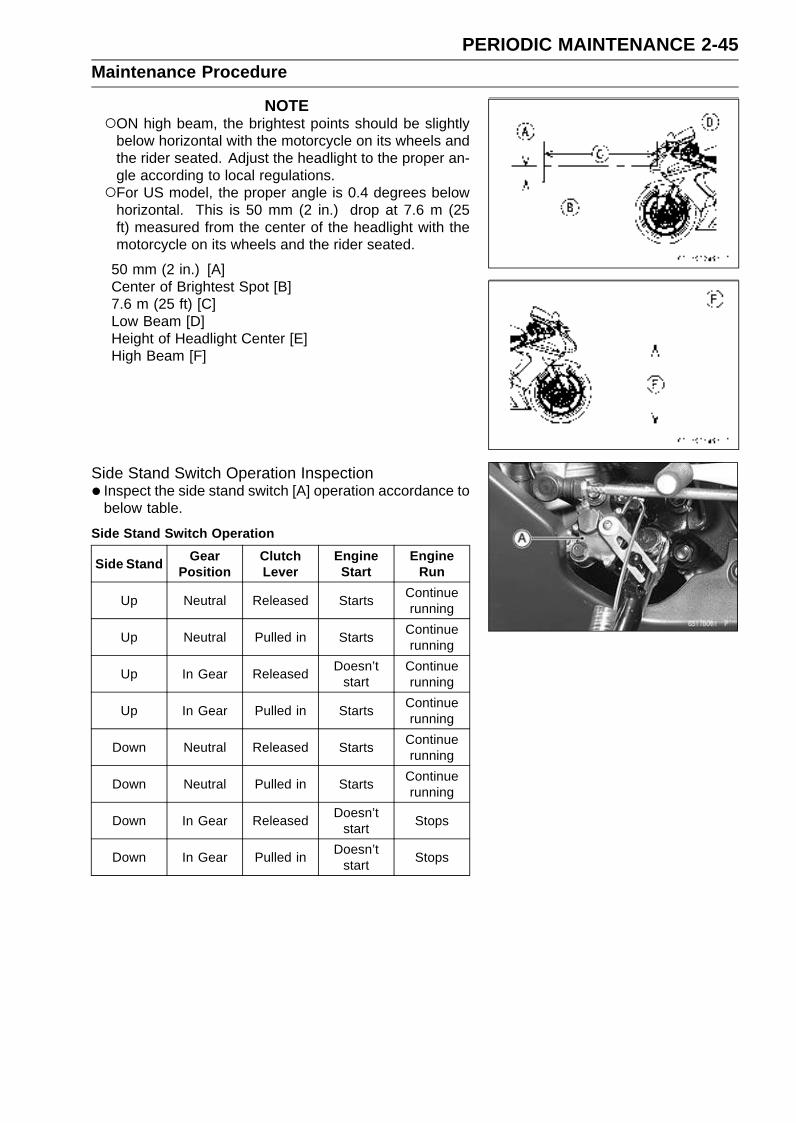
PERIODIC MAINTENANCE 2-45Maintenance Procedure
NOTEON high beam, the brightest points should be slightly
below horizontal with the motorcycle on its wheels andthe rider seated. Adjust the headlight to the proper an-gle according to local regulations.For US model, the proper angle is 0.4 degrees below
horizontal. This is 50 mm (2 in.) drop at 7.6 m (25ft) measured from the center of the headlight with themotorcycle on its wheels and the rider seated.
50 mm (2 in.) [A]Center of Brightest Spot [B]7.6 m (25 ft) [C]Low Beam [D]Height of Headlight Center [E]High Beam [F]
Side Stand Switch Operation Inspection• Inspect the side stand switch [A] operation accordance to
below table.
Side Stand Switch Operation
Side StandGear
PositionClutchLever
EngineStart
EngineRun
Up Neutral Released StartsContinuerunning
Up Neutral Pulled in StartsContinuerunning
Up In Gear ReleasedDoesn’t
startContinuerunning
Up In Gear Pulled in StartsContinuerunning
Down Neutral Released StartsContinuerunning
Down Neutral Pulled in StartsContinuerunning
Down In Gear ReleasedDoesn’t
startStops
Down In Gear Pulled inDoesn’t
startStops
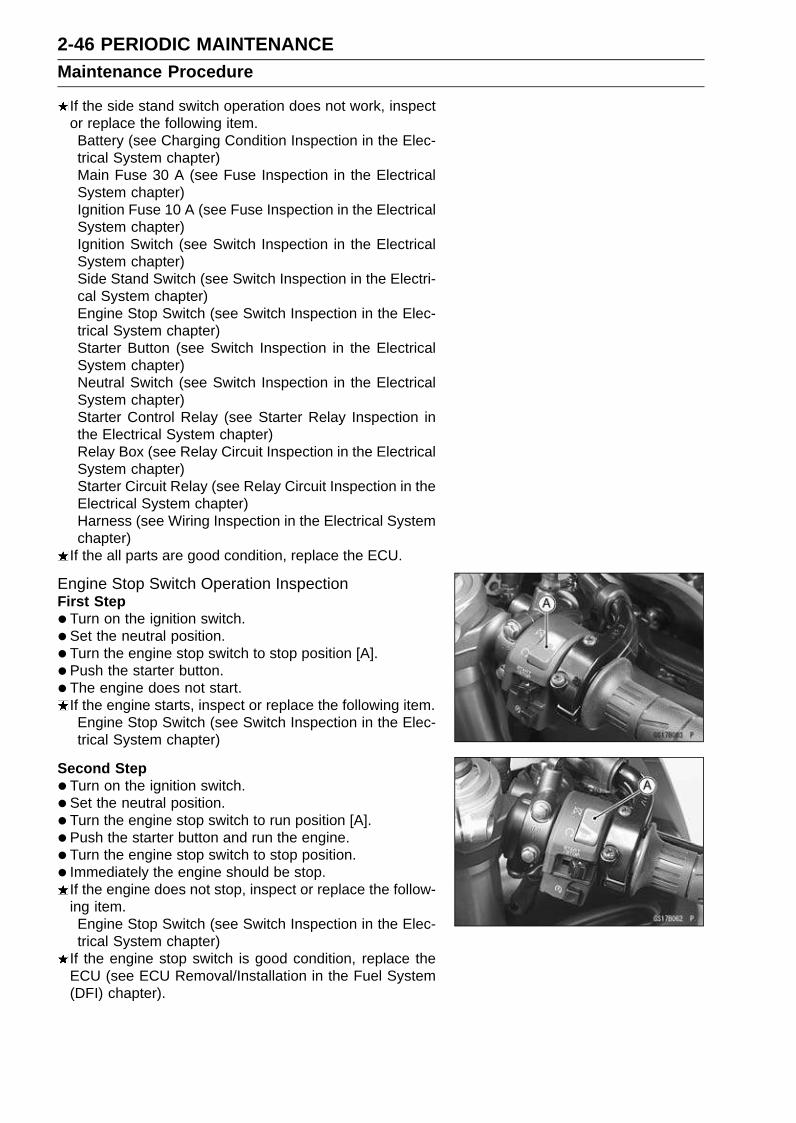
2-46 PERIODIC MAINTENANCEMaintenance Procedure
If the side stand switch operation does not work, inspector replace the following item.Battery (see Charging Condition Inspection in the Elec-trical System chapter)Main Fuse 30 A (see Fuse Inspection in the ElectricalSystem chapter)Ignition Fuse 10 A (see Fuse Inspection in the ElectricalSystem chapter)Ignition Switch (see Switch Inspection in the ElectricalSystem chapter)Side Stand Switch (see Switch Inspection in the Electri-cal System chapter)Engine Stop Switch (see Switch Inspection in the Elec-trical System chapter)Starter Button (see Switch Inspection in the ElectricalSystem chapter)Neutral Switch (see Switch Inspection in the ElectricalSystem chapter)Starter Control Relay (see Starter Relay Inspection inthe Electrical System chapter)Relay Box (see Relay Circuit Inspection in the ElectricalSystem chapter)Starter Circuit Relay (see Relay Circuit Inspection in theElectrical System chapter)Harness (see Wiring Inspection in the Electrical Systemchapter)
If the all parts are good condition, replace the ECU.
Engine Stop Switch Operation InspectionFirst Step
•Turn on the ignition switch.
• Set the neutral position.
• Turn the engine stop switch to stop position [A].
• Push the starter button.
• The engine does not start.If the engine starts, inspect or replace the following item.Engine Stop Switch (see Switch Inspection in the Elec-trical System chapter)
Second Step
•Turn on the ignition switch.
• Set the neutral position.
• Turn the engine stop switch to run position [A].
• Push the starter button and run the engine.
• Turn the engine stop switch to stop position.
• Immediately the engine should be stop.If the engine does not stop, inspect or replace the follow-ing item.Engine Stop Switch (see Switch Inspection in the Elec-trical System chapter)
If the engine stop switch is good condition, replace theECU (see ECU Removal/Installation in the Fuel System(DFI) chapter).

PERIODIC MAINTENANCE 2-47Maintenance Procedure
OthersChassis Parts Lubrication•Before lubricating each part, clean off any rusty spots with
rust remover and wipe off any grease, oil, dirt, or grime.
• Lubricate the points listed below with indicated lubricant.
NOTEWhenever the vehicle has been operated under
wet or rainy conditions, or especially after using ahigh-pressure water spray, perform the general lubri-cation
Pivots: Lubricate with Grease.Brake LeverBrake PedalClutch LeverRear Brake Joint PinSide Stand
Points: Lubricate with Grease.Clutch Inner Cable Upper and Lower Ends [A]Throttle Inner Cable Upper and Lower Ends
Cables: Lubricate with Rust InhibitorClutch CableThrottle Cables
• Lubricate the cables by seeping the oil between the cableand housing.The cable may be lubricated by using a commercially
available pressure cable lubricator with an aerosol cablelubricant.

2-48 PERIODIC MAINTENANCEMaintenance Procedure
•With the cable disconnected at both ends, the inner cableshould move freely [A] within the cable housing.If cable movement is not free after lubricating, if the cableis frayed [B], or if the cable housing is kinked [C], replacethe cable.
Bolts, Nuts and Fasteners Tightness Inspection•Check the tightness of the bolts and nuts listed here. Also,
check to see that each cotter pin is in place and in goodcondition.
NOTEFor the engine fasteners, check the tightness of them
when the engine is cold (at room temperature).
If there are loose fasteners, retorque them to the spec-ified torque following the specified tightening sequence.Refer to the appropriate chapter for torque specifications.If torque specifications are not in the appropriate chapter,see the Standard Torque Table. For each fastener, firstloosen it by 1/2 turn, then tighten it.If cotter pins are damaged, replace them with new ones.
PERIODIC MAINTENANCE 2-49Maintenance Procedure
Bolt, Nut and Fastener to be checkedEngine:
Clutch Lever Pivot NutEngine Mounting BoltsExhaust Pipe Clamp BoltsExhaust Pipe Manifold Holder NutsMuffler Body Mounting Bolts
Wheels:Front Axle Clamp BoltsFront Axle NutRear Axle NutRear Axle Nut Cotter Pin
Brakes:Brake Lever Pivot NutBrake Pedal BoltBrake Rod Joint Cotter PinCaliper Mounting BoltsFront Master Cylinder Clamp BoltsRear Master Cylinder Mounting Bolts
Suspension:Front Fork Clamp BoltsRear Shock Absorber Mounting NutsSwingarm Pivot Shaft NutUni-Trak Link Nuts
Steering:Handlebar BoltsSteering Stem Head Nut
Others:Footpeg Bracket BoltsFront Fender Mounting BoltsSide Stand Bolt

2-50 PERIODIC MAINTENANCEMaintenance Procedure
Replacement PartsAir Cleaner Element Replacement
NOTEIn dusty areas, the element should be replaced more
frequently than the recommended interval.After riding through rain or on muddy roads, the element
should be replaced immediately.
WARNINGIf dirt or dust is allowed to pass through into thethrottle assy, the throttle may become stuck, possi-bly causing an accident.
CAUTION
If dirt gets through into the engine, excessive en-gine wear and possibly engine damage will occur.
•Remove:Front Seat (see Front Seat Removal in the Frame chap-ter)
• Lift up the fuel tank, and clamp the fuel tank by wood.
•Remove:Air Cleaner Element Cover Screws [A]Air Cleaner Element Cover [B]
•Discard:Air Cleaner Element
• Install a new element [A].
CAUTION
Use only the recommended air cleaner element(Kawasaki part number 11013-0010). Using anotherair cleaner element will wear the engine prema-turely or lower the engine performance.
NOTEBe sure to install the fuel tank drain hose.
Fuel Hose Replacement•Remove the fuel tank (see Fuel Tank Removal in the Fuel
System (DFI) chapter).
• Be sure to place a piece of cloth [A] around the fuel hosejoint.
• Push [B] the joint lock claws [C].

PERIODIC MAINTENANCE 2-51Maintenance Procedure
•Pull the joint lock [A] as shown.
• Pull the fuel hose joint [B] out of the delivery pipe.
WARNINGBe prepared for fuel spillage; any spilled fuel mustbe completely wiped up immediately.When the fuel hose is disconnected, fuel spills outfrom the hose and the pipe. Cover the hose connec-tion with a clean shop towel to prevent fuel spillage.
• Install the new fuel hose.
• Pull [A] the joint lock [B] fully as shown.
• Insert the fuel hose joint [A] straight onto the delivery pipeuntil the hose joint clicks.
• Push [B] the joint lock [C] until the hose joint clicks.
• Push and pull [A] the fuel hose joint [B] back and forthmore than two times and make sure it is locked anddoesn’t come off.
WARNINGMake sure the fuel hose joint is installed correctlyon the delivery pipe or the fuel could leak.
If it comes off, reinstall the hose joint.
• Run the fuel hose in accordance with the Cable, Wire, andHose Routing section in the Appendix chapter.
• Install the removed parts (see appropriate chapters).
• Start the engine and check the fuel hose for leaks.
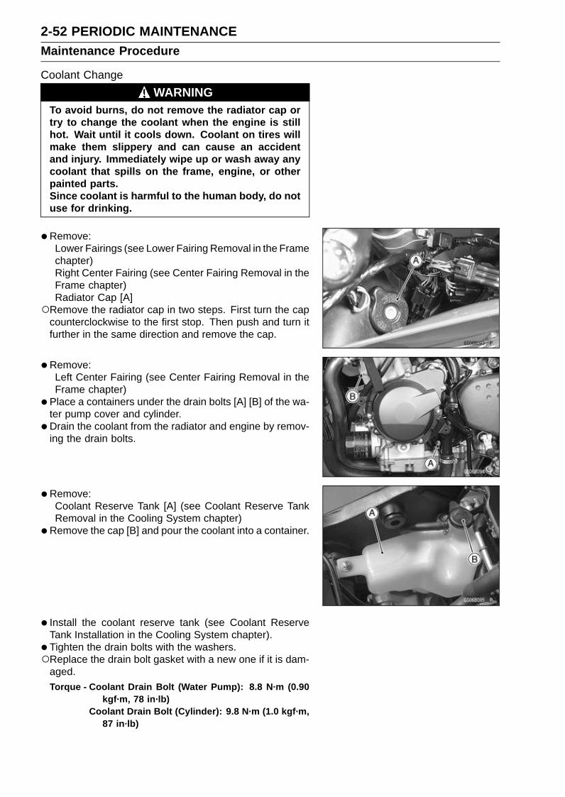
2-52 PERIODIC MAINTENANCEMaintenance Procedure
Coolant Change
WARNINGTo avoid burns, do not remove the radiator cap ortry to change the coolant when the engine is stillhot. Wait until it cools down. Coolant on tires willmake them slippery and can cause an accidentand injury. Immediately wipe up or wash away anycoolant that spills on the frame, engine, or otherpainted parts.Since coolant is harmful to the human body, do notuse for drinking.
•Remove:Lower Fairings (see Lower Fairing Removal in the Framechapter)Right Center Fairing (see Center Fairing Removal in theFrame chapter)Radiator Cap [A]
Remove the radiator cap in two steps. First turn the capcounterclockwise to the first stop. Then push and turn itfurther in the same direction and remove the cap.
•Remove:Left Center Fairing (see Center Fairing Removal in theFrame chapter)
• Place a containers under the drain bolts [A] [B] of the wa-ter pump cover and cylinder.
• Drain the coolant from the radiator and engine by remov-ing the drain bolts.
• Remove:Coolant Reserve Tank [A] (see Coolant Reserve TankRemoval in the Cooling System chapter)
•Remove the cap [B] and pour the coolant into a container.
• Install the coolant reserve tank (see Coolant ReserveTank Installation in the Cooling System chapter).
• Tighten the drain bolts with the washers.Replace the drain bolt gasket with a new one if it is dam-
aged.Torque - Coolant Drain Bolt (Water Pump): 8.8 N·m (0.90
kgf·m, 78 in·lb)Coolant Drain Bolt (Cylinder): 9.8 N·m (1.0 kgf·m,
87 in·lb)

PERIODIC MAINTENANCE 2-53Maintenance Procedure
•Fill the radiator up to the radiator filler neck [A] withcoolant, and install the radiator cap.
NOTEPour in the coolant slowly so that it can expel the air
from the engine and radiator.
•Fill the reserve tank up to the full level line with coolant,and install the cap.
CAUTION
Soft or distilled water must be used with the an-tifreeze (see below for antifreeze) in the cooling sys-tem.If hard water is used in the system, it causes scalesaccumulation in the water passages, and consider-ably reduces the efficiency of the cooling system.
Water and Coolant Mixture Ratio (Recommended)Soft Water: 50%
Coolant: 50%
Freezing Point: –35°C (–31°F)
Total Amount: 2.6 L (2.7 US qt)
NOTEChoose a suitable mixture ratio by referring to the
coolant manufacturer’s directions.
•Bleed the air from the cooling system as follows.Start the engine with the radiator cap removed and run it
until no more air bubbles [A] can be seen in the coolant.Tap the radiator hoses to force any air bubbles caught
inside.Stop the engine and add coolant up to the radiator filler
neck.
• Install the radiator cap.
• Start the engine, warm it up thoroughly until the radiatorfan turns on and then stop the engine.
•Check the coolant level in the reserve tank after the en-gine cools down.If the coolant level is lower than the low level line, addcoolant to the full level line.
CAUTION
Do not add more coolant above the full level line.
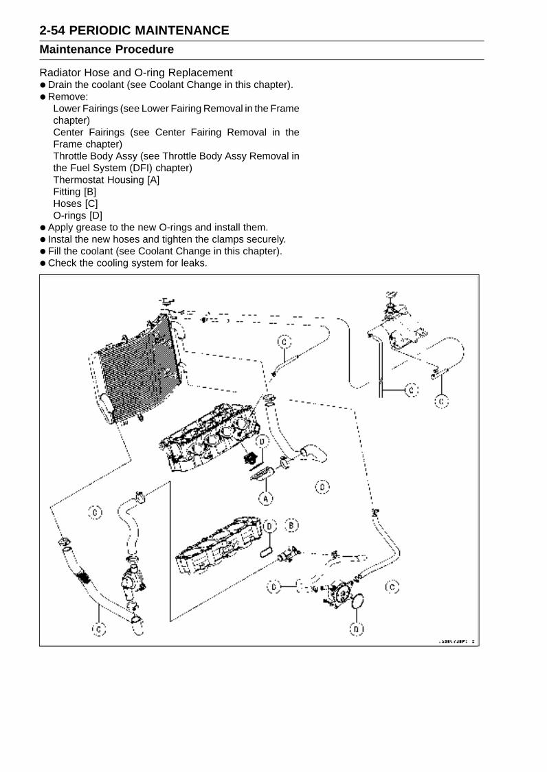
2-54 PERIODIC MAINTENANCEMaintenance Procedure
Radiator Hose and O-ring Replacement•Drain the coolant (see Coolant Change in this chapter).
• Remove:Lower Fairings (see Lower Fairing Removal in the Framechapter)Center Fairings (see Center Fairing Removal in theFrame chapter)Throttle Body Assy (see Throttle Body Assy Removal inthe Fuel System (DFI) chapter)Thermostat Housing [A]Fitting [B]Hoses [C]O-rings [D]
• Apply grease to the new O-rings and install them.
• Instal the new hoses and tighten the clamps securely.
• Fill the coolant (see Coolant Change in this chapter).
• Check the cooling system for leaks.

PERIODIC MAINTENANCE 2-55Maintenance Procedure
Engine Oil Change•Remove the lower fairings (see Lower Fairing Removal in
the Frame chapter).
• Situate the motorcycle so that it is vertical after warmingup the engine.
•Remove the engine oil drain bolt [A] to drain the oil.The oil in the oil filter can be drained by removing the filter
(see Oil Filter Replacement in this chapter).Replace the drain bolt gasket with a new one.
• Tighten the drain bolt.Torque - Engine Oil Drain Bolt: 29 N·m (3.0 kgf·m, 22 ft·lb)
•Pour in the specified type and amount of oil.
Recommended Engine OilType: API SE, SF or SG
API SH or SJ with JASO MA
Viscosity: SAE 10W-40
Capacity: 3.4 L (3.6 US qt) (when filter is notremoved)
3.6 L (3.8 US qt) (when filter is removed)
4.0 L (4.2 US qt) (when engine iscompletely dry)
NOTEAlthough 10W-40 engine oil is the recommended oil
for most conditions, the oil viscosity may need to bechanged to accommodate atmospheric conditions inyour riding area.
Oil Filter Replacement•Drain the engine oil (see Engine Oil Change in this chap-
ter).
• Remove the oil filter [A] with the oil filter wrench [B].Special Tool - Oil Filter Wrench: 57001-1249
•Replace the filter with a new one.
• Apply engine oil to the gasket [A] before installation.
• Tighten the filter with the oil filter wrench.Torque - Oil Filter: 31 N·m (3.2 kgf·m, 23 ft·lb)
NOTEHand tightening of the oil filter can not be allowed since
it does not reach to this tightening torque.
•Pour in the specified type and amount of oil (see EngineOil Change in this chapter).
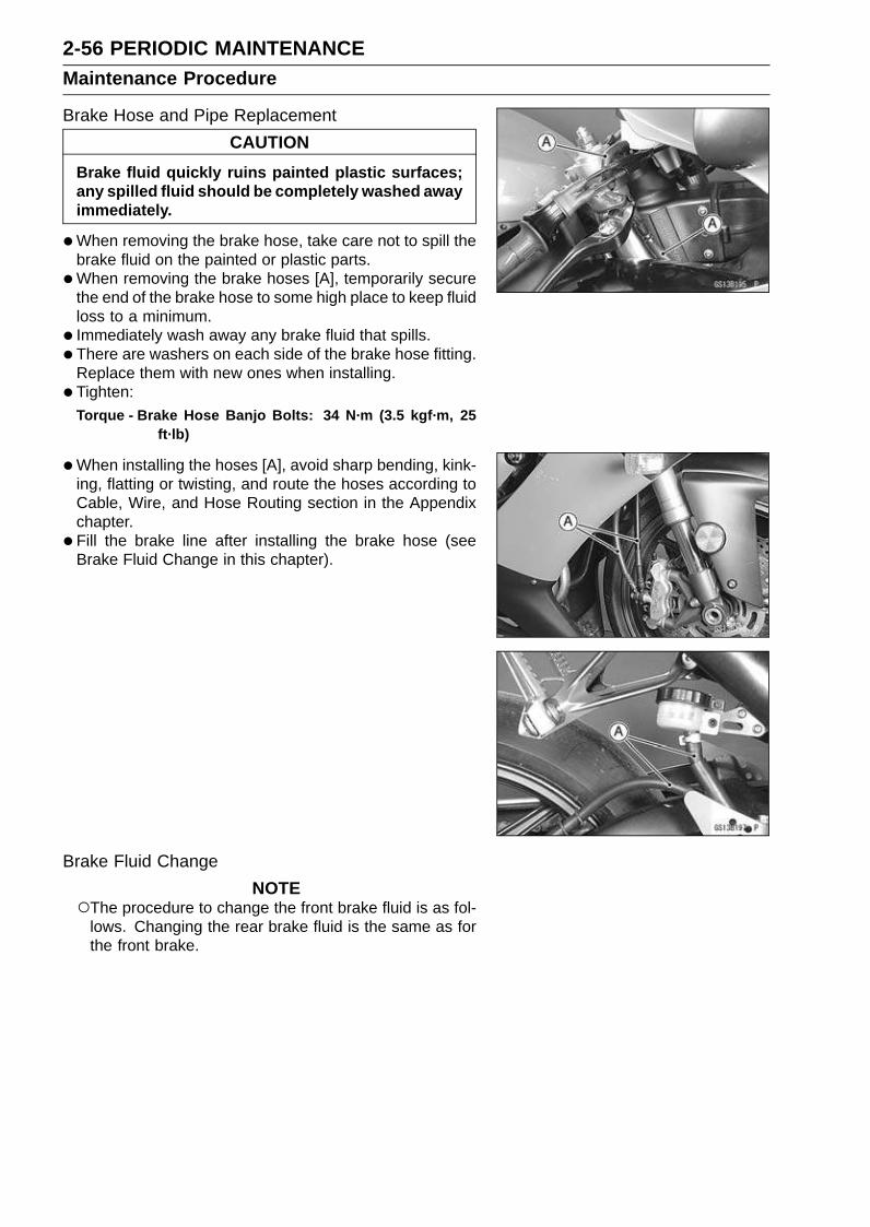
2-56 PERIODIC MAINTENANCEMaintenance Procedure
Brake Hose and Pipe Replacement
CAUTION
Brake fluid quickly ruins painted plastic surfaces;any spilled fluid should be completely washed awayimmediately.
•When removing the brake hose, take care not to spill thebrake fluid on the painted or plastic parts.
•When removing the brake hoses [A], temporarily securethe end of the brake hose to some high place to keep fluidloss to a minimum.
• Immediately wash away any brake fluid that spills.
• There are washers on each side of the brake hose fitting.Replace them with new ones when installing.
• Tighten:Torque - Brake Hose Banjo Bolts: 34 N·m (3.5 kgf·m, 25
ft·lb)
•When installing the hoses [A], avoid sharp bending, kink-ing, flatting or twisting, and route the hoses according toCable, Wire, and Hose Routing section in the Appendixchapter.
• Fill the brake line after installing the brake hose (seeBrake Fluid Change in this chapter).
Brake Fluid Change
NOTEThe procedure to change the front brake fluid is as fol-
lows. Changing the rear brake fluid is the same as forthe front brake.

PERIODIC MAINTENANCE 2-57Maintenance Procedure
• Level the brake fluid reservoir.
• Remove the reservoir cap.
•Remove the rubber cap from the bleed valve [A] on thecaliper.
• Attach a clear plastic hose [B] to the bleed valve, and runthe other end of the hose into a container.
• Fill the reservoir with fresh specified brake fluid.
•Change the brake fluid.Repeat this operation until fresh brake fluid comes out
from the plastic hose or the color of the fluid changes.1. Open the bleed valve [A].2. Apply the brake and hold it [B].3. Close the bleed valve [C].4. Release the brake [D].
NOTEThe fluid level must be checked often during the chang-
ing operation and replenished with fresh brake fluid. Ifthe fluid in the reservoir runs out any time during thechanging operation, the brakes will need to be bledsince air will have entered the brake line.Front Brake: Repeat the above steps for the other
caliper.
•Follow the procedure below to install the front/rear brakefluid reservoir cap correctly.First, tighten the front/rear brake fluid reservoir cap [B]
clockwise [C] by hand until the resistance is felt fully; then,tighten the cap an additional 1/6 turn [D] while holding thebrake fluid reservoir body [A].
• Tighten:Torque - Front Brake Reservoir Cap Stopper Screw: 1.2
N·m (0.12 kgf·m, 10 in·lb)
•Tighten the bleed valve, and install the rubber cap.Torque - Bleed Valve: 7.8 N·m (0.80 kgf·m, 69 in·lb)
•After changing the fluid, check the brake for good brakingpower, no brake drag, and no fluid leakage.If necessary, bleed the air from the lines.

2-58 PERIODIC MAINTENANCEMaintenance Procedure
Master Cylinder Rubber Parts ReplacementFront Master Cylinder Disassembly
•Remove the front master cylinder (see Front Master Cylin-der Removal in the Brakes chapter).
• Remove the seal cover [A], circlip [B], connector [C] andO-ring [D].Special Tool - Inside Circlip Pliers: 57001-143
•Unscrew the locknut [E] and pivot bolt [F], and remove thebrake lever.
• Pull the dust cover [G] and push rod [H] out of place, andremove the circlip [I].
• Pull out the piston assy [J].
• Replace:Seal Cover [A]Circlip [B]O-ring [D]Dust Cover [G]Circlip [I]Piston Assy [J]Diaphragm [K]
Rear Master Cylinder Disassembly
•Remove the rear master cylinder (see Rear Master Cylin-der Removal in the Brakes chapter).
• Remove the circlip [A], connector [B] and O-ring [C].Special Tool - Inside Circlip Pliers: 57001-143
•Slide the dust cover [D] out of place, and remove the cir-clip [E].
• Pull out the push rod assy [F].
• Take off the piston assy [G] and return spring [H].
CAUTION
Do not remove the secondary cup from the pistonsince removal will damage it.
•Replace:Circlip [A]O-ring [C]Circlip [E]Push Rod Assy [F]Piston Assy [G]Diaphragm [I]
Master Cylinder Assembly
•Before assembly, clean all parts including the mastercylinder with brake fluid or alcohol.
CAUTION
Except for the disc pads and disc, use only discbrake fluid, isopropyl alcohol, or ethyl alcohol forcleaning brake parts. Do not use any other fluid forcleaning these parts. Gasoline, engine oil, or anyother petroleum distillate will cause deterioration ofthe rubber parts. Oil spilled on any part will be diffi-cult to wash off completely, and will eventually de-teriorate the rubber used in the disc brake.
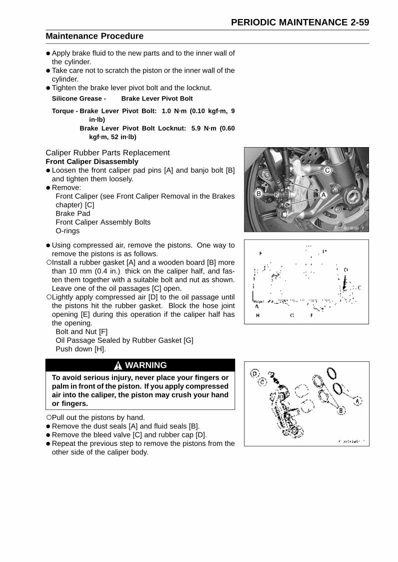
PERIODIC MAINTENANCE 2-59Maintenance Procedure
•Apply brake fluid to the new parts and to the inner wall ofthe cylinder.
• Take care not to scratch the piston or the inner wall of thecylinder.
• Tighten the brake lever pivot bolt and the locknut.Silicone Grease - Brake Lever Pivot Bolt
Torque - Brake Lever Pivot Bolt: 1.0 N·m (0.10 kgf·m, 9in·lb)
Brake Lever Pivot Bolt Locknut: 5.9 N·m (0.60kgf·m, 52 in·lb)
Caliper Rubber Parts ReplacementFront Caliper Disassembly
• Loosen the front caliper pad pins [A] and banjo bolt [B]and tighten them loosely.
•Remove:Front Caliper (see Front Caliper Removal in the Brakeschapter) [C]Brake PadFront Caliper Assembly BoltsO-rings
•Using compressed air, remove the pistons. One way toremove the pistons is as follows.Install a rubber gasket [A] and a wooden board [B] more
than 10 mm (0.4 in.) thick on the caliper half, and fas-ten them together with a suitable bolt and nut as shown.Leave one of the oil passages [C] open.Lightly apply compressed air [D] to the oil passage until
the pistons hit the rubber gasket. Block the hose jointopening [E] during this operation if the caliper half hasthe opening.Bolt and Nut [F]Oil Passage Sealed by Rubber Gasket [G]Push down [H].
WARNINGTo avoid serious injury, never place your fingers orpalm in front of the piston. If you apply compressedair into the caliper, the piston may crush your handor fingers.
Pull out the pistons by hand.
•Remove the dust seals [A] and fluid seals [B].
• Remove the bleed valve [C] and rubber cap [D].
• Repeat the previous step to remove the pistons from theother side of the caliper body.

2-60 PERIODIC MAINTENANCEMaintenance Procedure
NOTEIf compressed air is not available, do as follows for both
calipers coincidentally, with the brake hose connectedto the caliper.Prepare a container for brake fluid, and perform the
work above it.Remove the pad spring and pads (see Front Brake Pad
Removal in the Brakes chapter).Pump the brake lever until the pistons come out of the
cylinders, and then disassemble the caliper.
Front Caliper Assembly
•Clean the caliper parts except for the pads.
CAUTION
For cleaning the parts, use only disc brake fluid,isopropyl alcohol, or ethyl alcohol.
• Install the bleed valve and rubber cap.Torque - Bleed Valve: 7.8 N·m (0.80 kgf·m, 69 in·lb)
•Replace the fluid seals [A] with new ones.Apply brake fluid to the fluid seals, and install them into
the cylinders by hand.
•Replace the dust seals [B] with new ones if they are dam-aged.Apply brake fluid to the dust seals, and install them into
the cylinders by hand.
•Replace the O-ring [A].
• Apply brake fluid to the outside of the pistons, and pushthem into each cylinder by hand.
• Be sure to install the O-rings.
• Tighten:Torque - Front Caliper Assembly Bolts: 22 N·m (2.2 kgf·m,
16 ft·lb)
• Install the pads (see Front Brake Pad Installation in theBrakes chapter).
•Wipe up any spilled brake fluid on the caliper with wetcloth.
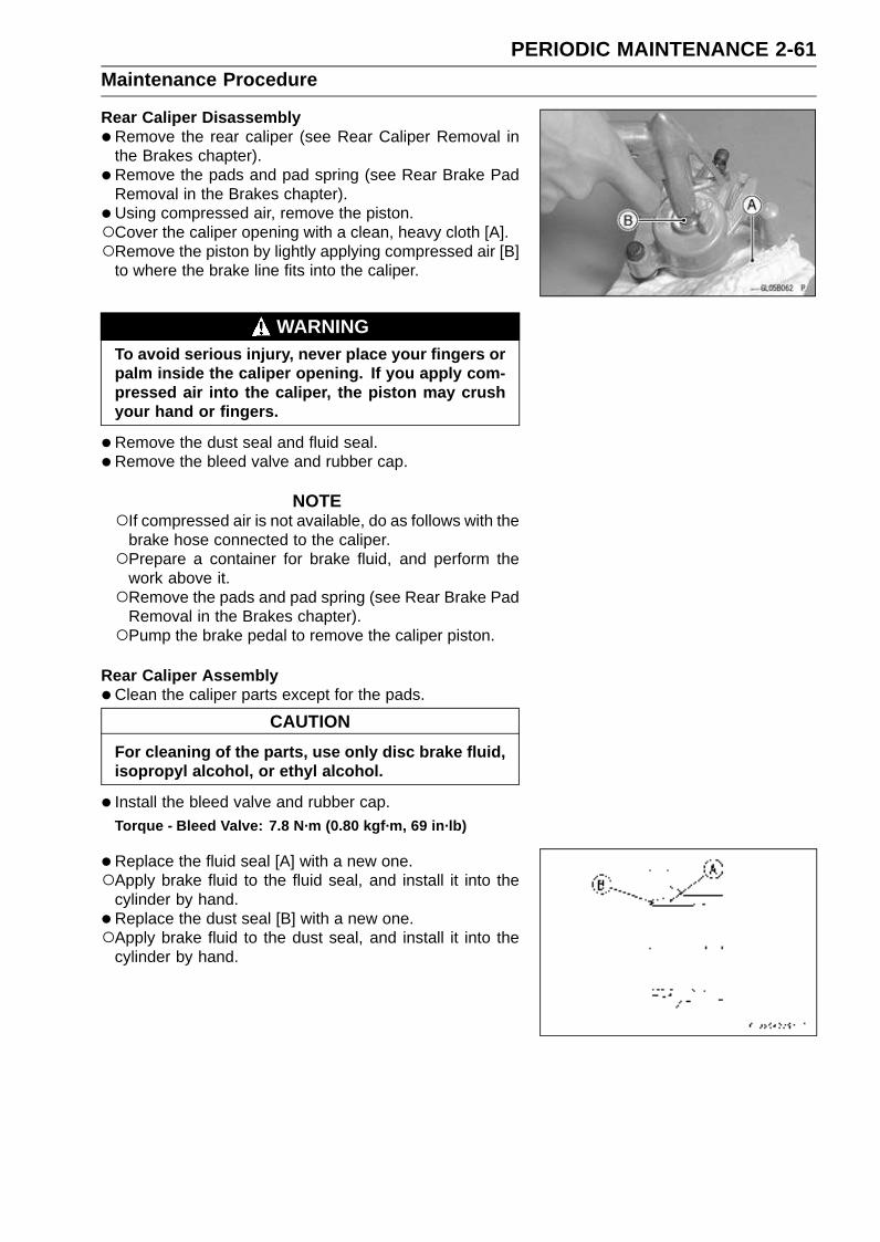
PERIODIC MAINTENANCE 2-61Maintenance Procedure
Rear Caliper Disassembly
•Remove the rear caliper (see Rear Caliper Removal inthe Brakes chapter).
• Remove the pads and pad spring (see Rear Brake PadRemoval in the Brakes chapter).
• Using compressed air, remove the piston.Cover the caliper opening with a clean, heavy cloth [A].Remove the piston by lightly applying compressed air [B]
to where the brake line fits into the caliper.
WARNINGTo avoid serious injury, never place your fingers orpalm inside the caliper opening. If you apply com-pressed air into the caliper, the piston may crushyour hand or fingers.
•Remove the dust seal and fluid seal.
• Remove the bleed valve and rubber cap.
NOTEIf compressed air is not available, do as follows with the
brake hose connected to the caliper.Prepare a container for brake fluid, and perform the
work above it.Remove the pads and pad spring (see Rear Brake Pad
Removal in the Brakes chapter).Pump the brake pedal to remove the caliper piston.
Rear Caliper Assembly
•Clean the caliper parts except for the pads.
CAUTION
For cleaning of the parts, use only disc brake fluid,isopropyl alcohol, or ethyl alcohol.
• Install the bleed valve and rubber cap.Torque - Bleed Valve: 7.8 N·m (0.80 kgf·m, 69 in·lb)
•Replace the fluid seal [A] with a new one.Apply brake fluid to the fluid seal, and install it into the
cylinder by hand.
•Replace the dust seal [B] with a new one.Apply brake fluid to the dust seal, and install it into the
cylinder by hand.
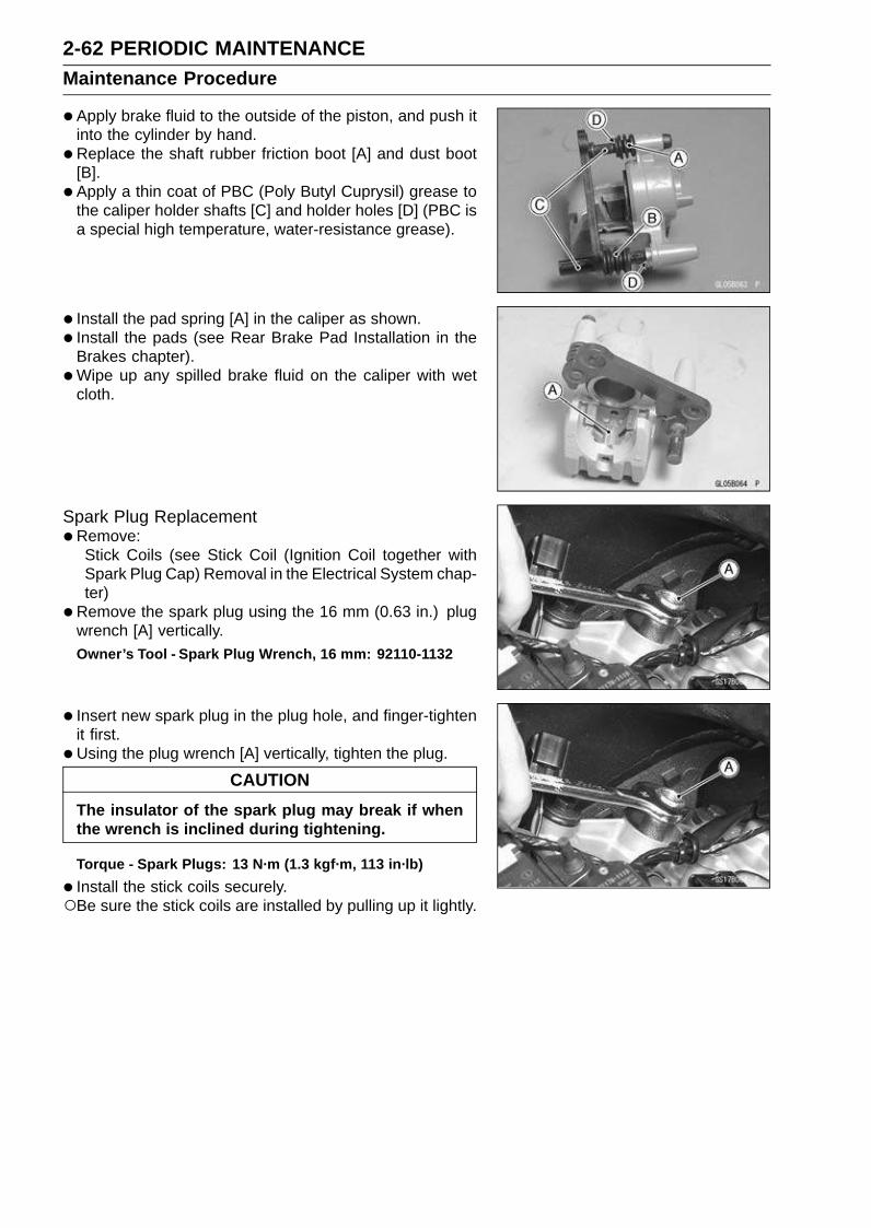
2-62 PERIODIC MAINTENANCEMaintenance Procedure
•Apply brake fluid to the outside of the piston, and push itinto the cylinder by hand.
•Replace the shaft rubber friction boot [A] and dust boot[B].
• Apply a thin coat of PBC (Poly Butyl Cuprysil) grease tothe caliper holder shafts [C] and holder holes [D] (PBC isa special high temperature, water-resistance grease).
• Install the pad spring [A] in the caliper as shown.
• Install the pads (see Rear Brake Pad Installation in theBrakes chapter).
•Wipe up any spilled brake fluid on the caliper with wetcloth.
Spark Plug Replacement•Remove:
Stick Coils (see Stick Coil (Ignition Coil together withSpark Plug Cap) Removal in the Electrical System chap-ter)
•Remove the spark plug using the 16 mm (0.63 in.) plugwrench [A] vertically.Owner’s Tool - Spark Plug Wrench, 16 mm: 92110-1132
• Insert new spark plug in the plug hole, and finger-tightenit first.
• Using the plug wrench [A] vertically, tighten the plug.
CAUTION
The insulator of the spark plug may break if whenthe wrench is inclined during tightening.
Torque - Spark Plugs: 13 N·m (1.3 kgf·m, 113 in·lb)
• Install the stick coils securely.Be sure the stick coils are installed by pulling up it lightly.

FUEL SYSTEM (DFI) 3-1
3
Fuel System (DFI)
Table of Contents
Exploded View................................... 3-3Specifications .................................... 3-10Special Tools and Sealant ................. 3-12DFI Parts Location............................. 3-14DFI System........................................ 3-16DFI Servicing Precautions ................. 3-21Troubleshooting the DFI System ....... 3-23
Outline ............................................ 3-23Inquiries to Rider............................. 3-27
DFI System Troubleshooting Guide .. 3-30Self-Diagnosis ................................... 3-38
Self-diagnosis Outline..................... 3-38Self-diagnosis Procedures.............. 3-38Service Code Clearing Procedures 3-39
Service Code Reading ................. 3-41Service Code Erasing .................. 3-41
Backups.......................................... 3-43Main Throttle Sensor (Service Code
11)................................................... 3-45Main Throttle Sensor
Removal/Adjustment ................. 3-45Input Voltage Inspection............... 3-45Output Voltage Inspection............ 3-46Resistance Inspection.................. 3-48
Inlet Air Pressure Sensor (ServiceCode 12) ......................................... 3-49
Removal....................................... 3-49Installation.................................... 3-49Input Voltage Inspection............... 3-49Output Voltage Inspection............ 3-50
Inlet Air Temperature Sensor (ServiceCode 13) ......................................... 3-54
Removal/Installation..................... 3-54Output Voltage Inspection............ 3-54Sensor Resistance Inspection ..... 3-55
Water Temperature Sensor (ServiceCode 14) ......................................... 3-57
Removal/Installation..................... 3-57Output Voltage Inspection............ 3-57Sensor Resistance Inspection ..... 3-58
Atmospheric Pressure Sensor(Service Code 15)........................... 3-59
Removal....................................... 3-59Installation.................................... 3-59Input Voltage Inspection............... 3-59Output Voltage Inspection............ 3-60
Crankshaft Sensor (Service Code21)................................................... 3-63
Crankshaft SensorRemoval/Installation.................. 3-63
Crankshaft Sensor Inspection...... 3-63Camshaft Position Sensor (Service
Code 23) ......................................... 3-64Camshaft Position Sensor
Removal/Installation.................. 3-64Camshaft Position Sensor
Inspection.................................. 3-64Speed Sensor (Service Code 24)...... 3-65
Speed Sensor Removal/Installa-tion ............................................ 3-65
Speed Sensor Inspection............. 3-65Input Voltage Inspection............... 3-65Output Voltage Inspection............ 3-65
Vehicle-down Sensor (Service Code31)................................................... 3-67
Removal....................................... 3-67Installation.................................... 3-67Inspection..................................... 3-67
Subthrottle Sensor (Service Code32)................................................... 3-70
Subthrottle SensorRemoval/Adjustment ................. 3-70
Input Voltage Inspection............... 3-70Output Voltage Inspection............ 3-71Resistance Inspection.................. 3-73
Exhaust Butterfly Valve ActuatorSensor (Service Code 34) .............. 3-74
Exhaust Butterfly Valve ActuatorSensor Inspection ..................... 3-74
Immobilizer Amplifier (Service Code35)................................................... 3-75
Antenna Resistance Inspection ... 3-75Amplifier Input Voltage Inspection 3-75
Blank Key Detection (Service Code36)................................................... 3-76
User Key Inspection..................... 3-76Stick Coils #1, #2, #3, #4: (Service
Code 51, 52, 53, 54) ....................... 3-78Removal/Installation..................... 3-78Input Voltage Inspection............... 3-78
Subthrottle Valve Actuator (ServiceCode 62) ......................................... 3-80

3-2 FUEL SYSTEM (DFI)
Subthrottle Valve ActuatorRemoval .................................... 3-80
Subthrottle Valve ActuatorInspection.................................. 3-80
Resistance Inspection.................. 3-80Input Voltage Inspection............... 3-81
Exhaust Butterfly Valve Actuator(Service Code 63)........................... 3-82
Exhaust Butterfly Valve ActuatorRemoval .................................... 3-82
Exhaust Butterfly Valve ActuatorInstallation ................................. 3-82
Exhaust Butterfly Valve ActuatorInspection.................................. 3-83
Output Voltage Inspection............ 3-84ECU................................................... 3-85
ECU Identification ........................ 3-85ECU Removal .............................. 3-85ECU Installation ........................... 3-86ECU Power Supply Inspection..... 3-86
DFI Power Source ............................. 3-88ECU Fuse Removal ..................... 3-88ECU Fuse Installation .................. 3-88ECU Fuse Inspection ................... 3-88
FI Indicator Light (LED) ..................... 3-89Light (LED) Inspection ................. 3-89
Fuel Line............................................ 3-90Fuel Pressure Inspection ............. 3-90Fuel Flow Rate Inspection ........... 3-91
Fuel Pump ......................................... 3-93Fuel Pump Removal .................... 3-93Fuel Pump Installation ................. 3-93Operation Inspection.................... 3-94Operating Voltage Inspection....... 3-94
Fuel Injectors ..................................... 3-96Audible Inspection........................ 3-96Injector Signal Test....................... 3-96Injector Resistance Inspection ..... 3-97Injector Unit Test .......................... 3-98Injector Voltage Inspection........... 3-99Injector Fuel Line Inspection ........ 3-101
Throttle Grip and Cables ................... 3-103
Free Play Inspection .................... 3-103Free Play Adjustment................... 3-103Cable Installation ......................... 3-103Cable Lubrication ......................... 3-103
Throttle Body Assy ............................ 3-104Idle Speed Inspection .................. 3-104Throttle Bore Cleaning ................. 3-104Synchronization Inspection .......... 3-104Synchronization Adjustment ........ 3-104Throttle Body Assy Removal........ 3-104Throttle Body Assy Installation..... 3-106Throttle Body Assy Disassembly . 3-106Throttle Body Assy Assembly ...... 3-107
Nozzle Assy....................................... 3-108Nozzle Assy Removal .................. 3-108Nozzle Assy Installation ............... 3-108Nozzle Assy Disassembly............ 3-108Nozzle Assy Assembly................. 3-109
Air Cleaner......................................... 3-111Element Removal......................... 3-111Element Installation...................... 3-111Air Cleaner Element Inspection ... 3-111Air Cleaner Housing Removal...... 3-111Air Cleaner Housing Installation... 3-112Air Cleaner Housing Disassembly 3-113Air Cleaner Housing Assembly .... 3-113Oil Draining .................................. 3-113Air Inlet Duct Removal ................. 3-113Air Inlet Duct Installation .............. 3-113
Fuel Tank........................................... 3-114Fuel Tank Removal ...................... 3-114Fuel Tank Installation ................... 3-116Fuel Tank and Cap Inspection ..... 3-117Fuel Tank Cleaning ...................... 3-117
Evaporative Emission Control System(California Model) ........................... 3-118
Parts Removal/Installation ........... 3-118Hose Inspection ........................... 3-118Separator Inspection.................... 3-118Separator Operation Test............. 3-119Canister Inspection ..................... 3-119

FUEL SYSTEM (DFI) 3-3Exploded View
Dummy Page

3-4 FUEL SYSTEM (DFI)Exploded View
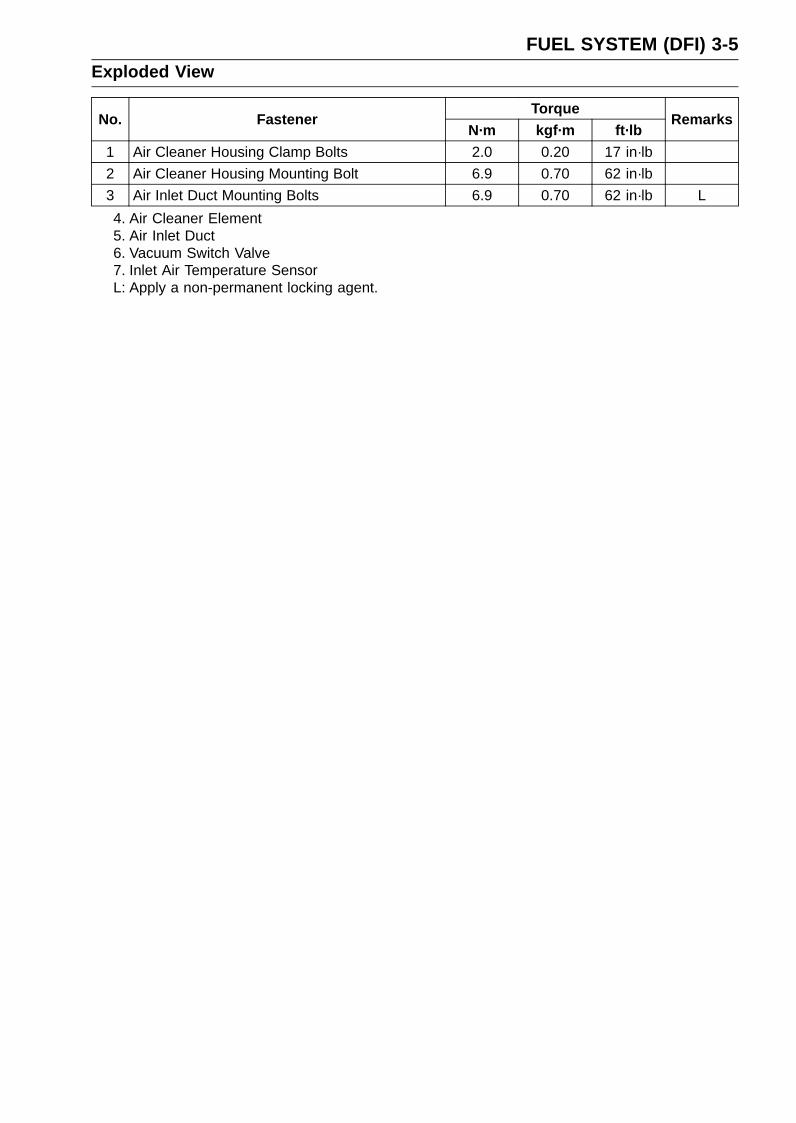
FUEL SYSTEM (DFI) 3-5Exploded View
TorqueNo. Fastener
N·m kgf·m ft·lbRemarks
1 Air Cleaner Housing Clamp Bolts 2.0 0.20 17 in·lb
2 Air Cleaner Housing Mounting Bolt 6.9 0.70 62 in·lb
3 Air Inlet Duct Mounting Bolts 6.9 0.70 62 in·lb L
4. Air Cleaner Element5. Air Inlet Duct6. Vacuum Switch Valve7. Inlet Air Temperature SensorL: Apply a non-permanent locking agent.
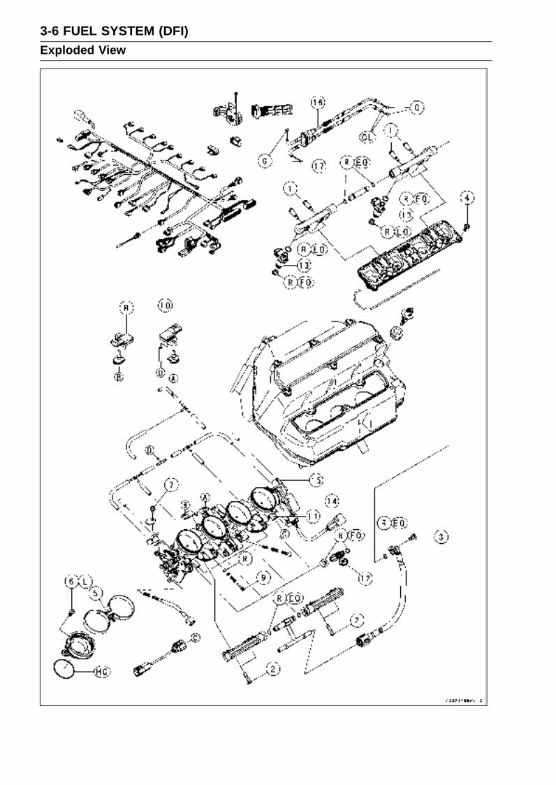
3-6 FUEL SYSTEM (DFI)Exploded View

FUEL SYSTEM (DFI) 3-7Exploded View
TorqueNo. Fastener
N·m kgf·m ft·lbRemarks
1 Delivery Pipe Mounting Screws (Nozzle Assy) 3.4 0.35 30 in·lb
2 Delivery Pipe Mounting Screws (Throttle Body) 3.4 0.35 30 in·lb
3 Fuel Hose Mounting Screw 4.9 0.50 43 in·lb
4 Nozzle Assy Mounting Bolts 6.9 0.70 61 in·lb
5 Throttle Body Assembly Holder Clamp Bolts 3.0 0.30 27 in·lb
6 Throttle Body Holder Bolts 12 1.2 104 in·lb L
7 Throttle Cable Holder Bolt 3.9 0.40 35 in·lb
8. Atmospheric Pressure Sensor9. Bypass Screw
10. Inlet Air Pressure Sensor11. Main Throttle Valve Sensor12. Primary Fuel Injectors13. Secondary Fuel Injectors14. Subthrottle Valve Actuator15. Subthrottle Valve Sensor16. Throttle Cable (Accelerator)17. Throttle Cable (Decelerator)CL: Apply cable lubricant.EO: Apply engine oil.
G: Apply grease.HG: Apply high-temperature grease.
L: Apply a non-permanent locking agent.R: Replacement Parts

3-8 FUEL SYSTEM (DFI)Exploded View
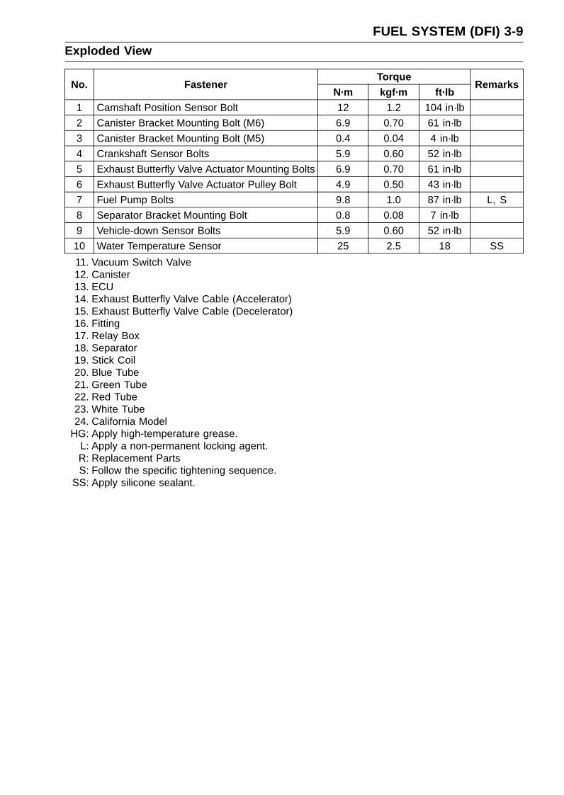
FUEL SYSTEM (DFI) 3-9Exploded View
TorqueNo. Fastener
N·m kgf·m ft·lbRemarks
1 Camshaft Position Sensor Bolt 12 1.2 104 in·lb
2 Canister Bracket Mounting Bolt (M6) 6.9 0.70 61 in·lb
3 Canister Bracket Mounting Bolt (M5) 0.4 0.04 4 in·lb
4 Crankshaft Sensor Bolts 5.9 0.60 52 in·lb
5 Exhaust Butterfly Valve Actuator Mounting Bolts 6.9 0.70 61 in·lb
6 Exhaust Butterfly Valve Actuator Pulley Bolt 4.9 0.50 43 in·lb
7 Fuel Pump Bolts 9.8 1.0 87 in·lb L, S
8 Separator Bracket Mounting Bolt 0.8 0.08 7 in·lb
9 Vehicle-down Sensor Bolts 5.9 0.60 52 in·lb
10 Water Temperature Sensor 25 2.5 18 SS
11. Vacuum Switch Valve12. Canister13. ECU14. Exhaust Butterfly Valve Cable (Accelerator)15. Exhaust Butterfly Valve Cable (Decelerator)16. Fitting17. Relay Box18. Separator19. Stick Coil20. Blue Tube21. Green Tube22. Red Tube23. White Tube24. California Model
HG: Apply high-temperature grease.L: Apply a non-permanent locking agent.R: Replacement PartsS: Follow the specific tightening sequence.
SS: Apply silicone sealant.
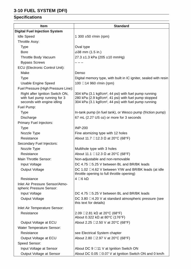
3-10 FUEL SYSTEM (DFI)Specifications
Item Standard
Digital Fuel Injection SystemIdle Speed 1 300 ±50 r/min (rpm)
Throttle Assy:
Type Oval type
Bore 38 mm (1.5 in.)
Throttle Body Vacuum 27.3 ±1.3 kPa (205 ±10 mmHg)
Bypass Screws – – –
ECU (Electronic Control Unit):
Make Denso
Type Digital memory type, with built in IC igniter, sealed with resin
Usable Engine Speed 100 ∼ 14 960 r/min (rpm)
Fuel Pressure (High Pressure Line):
Right after Ignition Switch ON,with fuel pump running for 3seconds with engine idling
304 kPa (3.1 kgf/cm², 44 psi) with fuel pump running280 kPa (2.9 kgf/cm², 41 psi) with fuel pump stopped304 kPa (3.1 kgf/cm², 44 psi) with fuel pump running
Fuel Pump:
Type In-tank pump (in fuel tank), or Wesco pump (friction pump)
Discharge 67 mL (2.27 US oz) or more for 3 seconds
Primary Fuel Injectors:
Type INP-200
Nozzle Type Fine atomizing type with 12 holes
Resistance About 11.7 ∼ 12.3 Ω at 20°C (68°F)
Secondary Fuel Injectors:
Nozzle Type Multihole type with 3 holes
Resistance About 11.1 ∼ 12.3 Ω at 20°C (68°F)
Main Throttle Sensor: Non-adjustable and non-removable
Input Voltage DC 4.75 ∼ 5.25 V between BL and BR/BK leads
Output Voltage DC 1.02 ∼ 4.62 V between Y/W and BR/BK leads (at idlethrottle opening to full throttle opening)
Resistance 4 ∼ 6 kΩInlet Air Pressure Sensor/Atmo-spheric Pressure Sensor:
Input Voltage DC 4.75 ∼ 5.25 V between BL and BR/BK leads
Output Voltage DC 3.80 ∼ 4.20 V at standard atmospheric pressure (seethis text for details)
Inlet Air Temperature Sensor:
Resistance 2.09 ∼ 2.81 kΩ at 20°C (68°F)About 0.322 kΩ at 80°C (176°F)
Output Voltage at ECU About 2.25 ∼ 2.50 V at 20°C (68°F)
Water Temperature Sensor:
Resistance see Electrical System chapter
Output Voltage at ECU About 2.80 ∼ 2.97 V at 20°C (68°F)
Speed Sensor:
Input Voltage at Sensor About DC 9 ∼ 11 V at Ignition Switch ON
Output Voltage at Sensor About DC 0.05 ∼ 0.07 V at Ignition Switch ON and 0 km/h
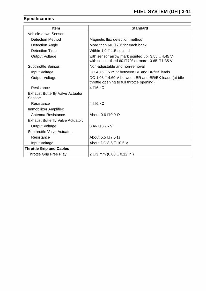
FUEL SYSTEM (DFI) 3-11Specifications
Item StandardVehicle-down Sensor:
Detection Method Magnetic flux detection method
Detection Angle More than 60 ∼ 70° for each bank
Detection Time Within 1.0 ∼ 1.5 second
Output Voltage with sensor arrow mark pointed up: 3.55 ∼ 4.45 Vwith sensor tilted 60 ∼ 70° or more: 0.65 ∼ 1.35 V
Subthrottle Sensor: Non-adjustable and non-removal
Input Voltage DC 4.75 ∼ 5.25 V between BL and BR/BK leads
Output Voltage DC 1.08 ∼ 4.60 V between BR and BR/BK leads (at idlethrottle opening to full throttle opening)
Resistance 4 ∼ 6 kΩExhaust Butterfly Valve ActuatorSensor:
Resistance 4 ∼ 6 kΩImmobilizer Amplifier:
Antenna Resistance About 0.6 ∼ 0.9 ΩExhaust Butterfly Valve Actuator:
Output Voltage 3.46 ∼ 3.76 V
Subthrottle Valve Actuator:
Resistance About 5.5 ∼ 7.5 ΩInput Voltage About DC 8.5 ∼ 10.5 V
Throttle Grip and CablesThrottle Grip Free Play 2 ∼ 3 mm (0.08 ∼ 0.12 in.)

3-12 FUEL SYSTEM (DFI)Special Tools and Sealant
Oil Pressure Gauge, 5 kgf/cm²:57001-125
Fork Oil Level Gauge:57001-1290
Hand Tester:57001-1394
Throttle Sensor Setting Adapter #1:57001-1400
Peak Voltage Adapter:57001-1415
Needle Adapter Set:57001-1457
Throttle Sensor Setting Adapter:57001-1538
Sensor Harness Adapter:57001-1561
Fuel Pressure Gauge Adapter:57001-1593
Fuel Hose:57001-1607
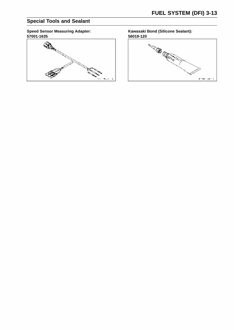
FUEL SYSTEM (DFI) 3-13Special Tools and Sealant
Speed Sensor Measuring Adapter:57001-1635
Kawasaki Bond (Silicone Sealant):56019-120

3-14 FUEL SYSTEM (DFI)DFI Parts Location
Subthrottle Sensor [A]Subthrottle Valve Actuator [B]Fuel Injectors (Primary) #1, #2, #3, #4 [C]
Water Temperature Sensor [A]Main Throttle Sensor [B]Inlet Air Pressure Sensor [C]Stick Coils #1, #2, #3, #4 [D]Subthrottle Valve Actuator [E]Subthrottle Sensor [F]Atmospheric Pressure Sensor [G]
Battery [A]Relay Box [B]Exhaust Butterfly Valve Actuator [C]ECU (Electronic Control Unit) [D]
Self-diagnosis Terminal [A]Kawasaki Diagnosis System (KDS) Connector [B]Vehicle-down Sensor [C]
Inlet Air Temperature Sensor [A]
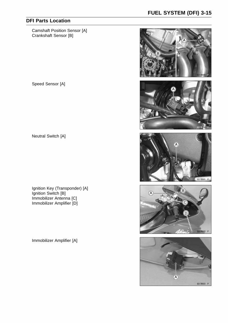
FUEL SYSTEM (DFI) 3-15DFI Parts Location
Camshaft Position Sensor [A]Crankshaft Sensor [B]
Speed Sensor [A]
Neutral Switch [A]
Ignition Key (Transponder) [A]Ignition Switch [B]Immobilizer Antenna [C]Immobilizer Amplifier [D]
Immobilizer Amplifier [A]
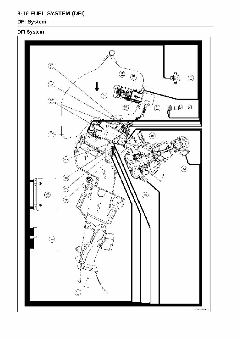
3-16 FUEL SYSTEM (DFI)DFI System
DFI System

FUEL SYSTEM (DFI) 3-17DFI System
1. ECU (Electrical Control Unit)2. Crankshaft Sensor3. Camshaft Position Sensor4. Main Throttle Sensor5. Subthrottle Sensor6. Subthrottle Valve Actuator7. Inlet Air Pressure Sensor8. Atmospheric Pressure Sensor9. Water Temperature Sensor
10. Inlet Air Temperature Sensor11. Vehicle-down Sensor12. Fuel Injectors13. Delivery Pipe14. Pressure Regulator15. Fuel Filter16. Fuel Pump17. Speed Sensor18. Battery19. Air Flow20. Fuel Flow

3-18 FUEL SYSTEM (DFI)DFI System
DFI System Wiring Diagram

FUEL SYSTEM (DFI) 3-19DFI System
Part Name1. Engine Stop Switch2. Starter Button3. Water Temperature Sensor4. Vehicle-down Sensor5. Subthrottle Valve Actuator6. Primary Fuel Injector #17. Primary Fuel Injector #28. Primary Fuel Injector #39. Primary Fuel Injector #4
10. Secondary Fuel Injector #111. Secondary Fuel Injector #212. Secondary Fuel Injector #313. Secondary Fuel Injector #414. Speed Sensor15. Camshaft Position Sensor16. Inlet Air Temperature Sensor17. Atmospheric Pressure Sensor18. Subthrottle Sensor19. Main Throttle Sensor20. Inlet Air Pressure Sensor21. Crankshaft Sensor22. ECU (Electronic Control Unit)23. FI Warning Indicator LED24. Water Temperature Gauge25. Speedometer26. Ignition Switch27. Stick Coil #1, #2, #3, #428. ECU Fuse 15 A29. Ignition Fuse 10 A30. Fuse Box31. ECU Main Relay32. Fuel Pump Relay33. Relay Box34. Main Fuse 30 A35. Battery36. Fuel Pump37. Self-diagnosis Terminal

3-20 FUEL SYSTEM (DFI)DFI System
Terminal Numbers of ECU Connectors
Terminal Names1. Subthrottle Valve Actuator Output Signal 22. Subthrottle Valve Actuator Output Signal 13. Exhaust Butterfly Valve Actuator (–)4. Exhaust Butterfly Valve Actuator (+)5. Exhaust Butterfly Valve Sensor6. Speed Sensor Output Signal7. Main Throttle Sensor Output Signal8. Inlet Air Pressure Sensor Output Signal9. Water Temperature Sensor Output Signal
10. Power Supply to Sensors11. Vehicle-down Sensor Output Signal12. Camshaft Position Sensor (+) Output Signal13. Crankshaft Sensor (+) Output Signal14. Immobilizer Communication Line15. Immobilizer Communication Line16. Power Supply to ECU (from ECU Main Re-
lay)17. Power Supply to ECU (from Battery)18. Subthrottle Valve Actuator Output Signal 419. Subthrottle Valve Actuator Output Signal 320. Unused21. Unused22. Unused23. Unused24. Subthrottle Sensor Output Signal25. Atmospheric Pressure Sensor Output Sig-
nal26. Inlet Air Temperature Sensor Output Signal27. Unused28. Ground to Sensors29. Camshaft Position Sensor (–) Output Signal30. Crankshaft Sensor (–) Output Signal
31. Immobilizer Communication Line32. External Diagnosis System Signal33. Unused34. Ground to ECU35. Engine Stop Switch Output Signal36. Starter Lockout Switch Output Signal37. Starter Button Output Signal38. Fuel Pump Relay Output Signal39. Unused40. Radiator Fan Signal41. Secondary Fuel Injector #2 Output Signal42. Secondary Fuel Injector #1 Output Signal43. Primary Fuel Injector #2 Output Signal44. Primary Fuel Injector #1 Output Signal45. Stick Coil #3 Output Signal46. Stick Coil #2 Output Signal47. Stick Coil #1 Output Signal48. Side Stand Switch Signal49. Self-diagnosis Terminal50. External Communication Line (Mode
Switch)51. Tachometer Output Signal52. FI Indicator LED Light53. Unused54. Secondary Fuel Injector #4 Output Signal55. Secondary Fuel Injector #3 Output Signal56. Primary Fuel Injector #4 Output Signal57. Primary Fuel Injector #3 Output Signal58. Ground for Fuel System59. Ground for Ignition System60. Stick Coil #4 Output Signal
FUEL SYSTEM (DFI) 3-21DFI Servicing Precautions
There are a number of important precautions that shouldbe followed servicing the DFI system.
This DFI system is designed to be used with a 12 V sealedbattery as its power source. Do not use any other batteryexcept for a 12 V sealed battery as a power source.Do not reverse the battery cable connections. This will
damage the ECU.To prevent damage to the DFI parts, do not disconnect the
battery cables or any other electrical connections whenthe ignition switch is ON, or while the engine is running.Take care not to short the leads that are directly con-
nected to the battery positive (+) terminal to the chassisground.When charging, remove the battery from the motorcycle.
This is to prevent ECU damage by excessive voltage.Whenever the DFI electrical connections are to be discon-
nected, first turn off the ignition switch. Conversely, makesure that all the DFI electrical connections are firmly re-connected before starting the engine.Do not turn the ignition switch ON while any of the DFI
electrical connectors are disconnected. The ECU memo-rizes service codes.Do not spray water on the electrical parts, DFI parts, con-
nectors, leads, and wiring.If a transceiver is installed on the motorcycle, make sure
that the operation of the DFI system is not influenced byelectric wave radiated from the antenna. Check operationof the system with the engine at idle. Locate the antennaas far as possible away from the ECU.When any fuel hose is disconnected, do not turn on the
ignition switch. Otherwise, the fuel pump will operate andfuel will spout from the fuel hose.Do not operate the fuel pump if the pump is completely
dry. This is to prevent pump seizure.Before removing the fuel system parts, blow the outer sur-
faces of these parts clean with compressed air.When any fuel hose is disconnected, fuel may spout out
by residual pressure in the fuel line. Cover the hose jointwith a piece of clean cloth to prevent fuel spillage.When installing the fuel hoses, avoid sharp bending, kink-
ing, flattening or twisting, and route the fuel hoses with aminimum of bending so that the fuel flow will not be ob-structed.Route the hoses according to Cable, Wire, and Hose
Routing section in the Appendix chapter.Replace the fuel hose if it has been sharply bent or kinked.

3-22 FUEL SYSTEM (DFI)DFI Servicing Precautions
The motorcycle is not properly handled, the high pressureinside the fuel line can cause fuel to leak or the hose toburst. Bend and twist the fuel hose while examining it.Replace the hose if any cracks or bulges are noticed.
To maintain the correct fuel/air mixture (F/A), there mustbe no inlet air leaks in the DFI system. Be sure to installthe oil filler plug [A] after filling the engine oil.Clutch Cover [B]
Torque - Oil Filler Plug: 1.5 N·m (0.15 kgf·m, 13 in·lb)

FUEL SYSTEM (DFI) 3-23Troubleshooting the DFI System
OutlineWhen an abnormality in the system occurs, the FI indi-
cator light (LED) goes on to alert the rider on the meterpanel. In addition, the condition of the problem is storedin the memory of the ECU (Electronic Control Unit). Withthe engine stopped and turned in the self-diagnosis mode,the service code [A] is indicated by the number of times theFI indicator light (LED) blinks.
When due to a malfunction, the FI indicator light (LED) re-mains lit, ask the rider about the conditions [B] under whichthe problem occurred and try to determine the cause [C].Don’t rely solely on the DFI self-diagnosis function, usecommon sense; first conduct a pre-diagnosis inspection,check the ECU for ground and power supply, the fuel line forno fuel leaks, and for correct pressure. The pre-diagnosisitems are not indicated by the FI indicator light (LED).
Even when the DFI system is operating normally, the FIindicator light (LED) [A] may light up under strong electricalinterference. No remedy needed. Turn the ignition switchOFF to stop the indicator light.
When the FI indicator light (LED) goes on and the motor-cycle is brought in for repair, check the service codes.
When the repair has been done, the light (LED) doesn’t goon. But the service codes stored in memory are not erasedto preserve the problem history, and the light (LED) candisplay the codes in the self-diagnosis mode. The problemhistory is referred when solving unstable problems.
Much of the DFI system troubleshooting work consistsof confirming continuity of the wiring. The DFI parts areassembled and adjusted with precision, and it is impossibleto disassemble or repair them.
•When checking the DFI parts, use a digital meter whichcan be read two decimal place voltage or resistance.Remove:
Rear Seat (see Rear Seat Removal in the Frame chap-ter)Front Seat (see Front Seat Removal in the Frame chap-ter)Seat Cover (see Seat Cover Removal in the Framechapter)
The DFI part connectors have seals, including the ECU.When measuring the input or output voltage with theconnector joined, use the needle adapter set. Insert theneedle adapter inside the seal until the needle adapterreaches the terminal.Special Tool - Needle Adapter Set: 57001-1457
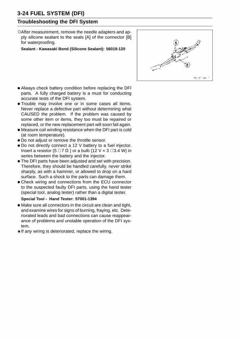
3-24 FUEL SYSTEM (DFI)Troubleshooting the DFI System
After measurement, remove the needle adapters and ap-ply silicone sealant to the seals [A] of the connector [B]for waterproofing.Sealant - Kawasaki Bond (Silicone Sealant): 56019-120
•Always check battery condition before replacing the DFIparts. A fully charged battery is a must for conductingaccurate tests of the DFI system.
• Trouble may involve one or in some cases all items.Never replace a defective part without determining whatCAUSED the problem. If the problem was caused bysome other item or items, they too must be repaired orreplaced, or the new replacement part will soon fail again.
•Measure coil winding resistance when the DFI part is cold(at room temperature).
• Do not adjust or remove the throttle sensor.
•Do not directly connect a 12 V battery to a fuel injector.Insert a resistor (5 ∼ 7 Ω ) or a bulb (12 V × 3 ∼ 3.4 W) inseries between the battery and the injector.
• The DFI parts have been adjusted and set with precision.Therefore, they should be handled carefully, never strikesharply, as with a hammer, or allowed to drop on a hardsurface. Such a shock to the parts can damage them.
•Check wiring and connections from the ECU connectorto the suspected faulty DFI parts, using the hand tester(special tool, analog tester) rather than a digital tester.Special Tool - Hand Tester: 57001-1394
•Make sure all connectors in the circuit are clean and tight,and examine wires for signs of burning, fraying, etc. Dete-riorated leads and bad connections can cause reappear-ance of problems and unstable operation of the DFI sys-tem.If any wiring is deteriorated, replace the wiring.

FUEL SYSTEM (DFI) 3-25Troubleshooting the DFI System
•Pull each connector [A] apart and inspect it for corrosion,dirt, and damage.If the connector is corroded or dirty, clean it carefully. If itis damaged, replace it. Connect the connectors securely.
• Check the wiring for continuity.Use the wiring diagram to find the ends of the lead which
is suspected of being a problem.Connect the hand tester between the ends of the leads.Set the tester to the × 1 Ω range, and read the tester.
If the tester does not read 0 Ω, the lead is defective. Re-place the lead or the main harness or the sub harness.
If both ends of a harness [A] are far apart, ground [B] theone end [C], using a jumper lead [D] and check the con-tinuity between the end [E] and the ground [F]. This en-ables to check a long harness for continuity. If the harnessis open, repair or replace the harness.
When checking a harness [A] for short circuit, open oneend [B] and check the continuity between the other end[C] and ground [D]. If there is continuity, the harness hasa short circuit to ground, and it must be repaired or re-placed.
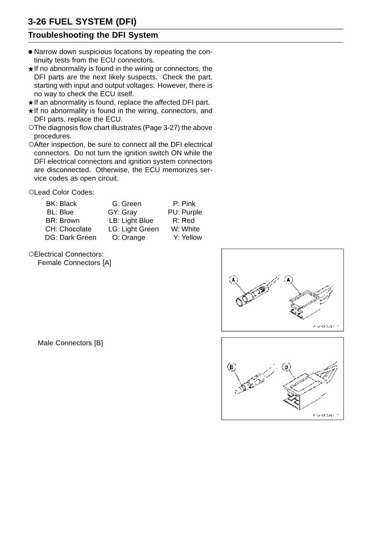
3-26 FUEL SYSTEM (DFI)Troubleshooting the DFI System
•Narrow down suspicious locations by repeating the con-tinuity tests from the ECU connectors.If no abnormality is found in the wiring or connectors, theDFI parts are the next likely suspects. Check the part,starting with input and output voltages. However, there isno way to check the ECU itself.If an abnormality is found, replace the affected DFI part.If no abnormality is found in the wiring, connectors, andDFI parts, replace the ECU.The diagnosis flow chart illustrates (Page 3-27) the above
procedures.After inspection, be sure to connect all the DFI electrical
connectors. Do not turn the ignition switch ON while theDFI electrical connectors and ignition system connectorsare disconnected. Otherwise, the ECU memorizes ser-vice codes as open circuit.
Lead Color Codes:
BK: BlackBL: BlueBR: BrownCH: ChocolateDG: Dark Green
G: GreenGY: GrayLB: Light BlueLG: Light Green
O: Orange
P: PinkPU: Purple
R: RedW: WhiteY: Yellow
Electrical Connectors:Female Connectors [A]
Male Connectors [B]

FUEL SYSTEM (DFI) 3-27Troubleshooting the DFI System
DFI Diagnosis Flow Chart
Inquiries to RiderEach rider reacts to problems in different ways, so it is important to confirm what kind of symptoms
the rider has encountered.Try to find out exactly what problem occurred under exactly what conditions by asking the rider;
knowing this information may help you reproduce the problem.The diagnosis sheet will help prevent you from overlooking any areas, and will help you decide if it
is a DFI system problem, or a general engine problem.
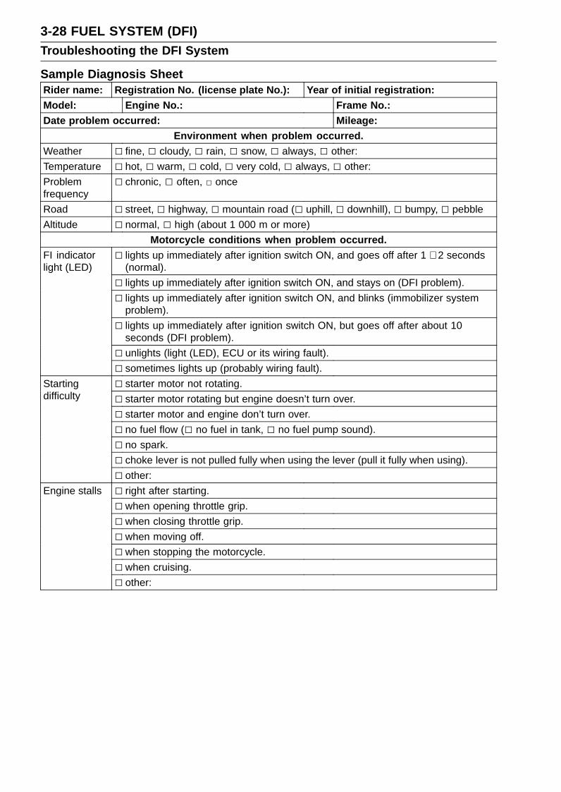
3-28 FUEL SYSTEM (DFI)Troubleshooting the DFI System
Sample Diagnosis SheetRider name: Registration No. (license plate No.): Year of initial registration:Model: Engine No.: Frame No.:Date problem occurred: Mileage:
Environment when problem occurred.Weather fine, cloudy, rain, snow, always, other:
Temperature hot, warm, cold, very cold, always, other:
Problemfrequency
chronic, often, once
Road street, highway, mountain road ( uphill, downhill), bumpy, pebble
Altitude normal, high (about 1 000 m or more)
Motorcycle conditions when problem occurred. lights up immediately after ignition switch ON, and goes off after 1 ∼ 2 seconds
(normal).
lights up immediately after ignition switch ON, and stays on (DFI problem).
lights up immediately after ignition switch ON, and blinks (immobilizer systemproblem).
FI indicatorlight (LED)
lights up immediately after ignition switch ON, but goes off after about 10seconds (DFI problem).
unlights (light (LED), ECU or its wiring fault).
sometimes lights up (probably wiring fault).
starter motor not rotating.Startingdifficulty starter motor rotating but engine doesn’t turn over.
starter motor and engine don’t turn over.
no fuel flow ( no fuel in tank, no fuel pump sound).
no spark.
choke lever is not pulled fully when using the lever (pull it fully when using).
other:
Engine stalls right after starting.
when opening throttle grip.
when closing throttle grip.
when moving off.
when stopping the motorcycle.
when cruising.
other:

FUEL SYSTEM (DFI) 3-29Troubleshooting the DFI System
very low idle speed, very high idle speed, rough idle speed.Poor running at lowspeed battery voltage is low (charge the battery).
spark plug loose (tighten it).
spark plug dirty, broken, or gap maladjusted (remedy it).
backfiring.
afterfiring.
hesitation when acceleration.
engine oil viscosity too high.
brake dragging.
engine overheating.
clutch slipping.
other:
spark plug loose (tighten it).Poor running or nopower at high speed spark plug dirty, broken, or gap maladjusted (remedy it).
spark plug incorrect (replace it).
knocking (fuel poor quality or incorrect, → use high-octane gasoline).
brake dragging.
clutch slipping.
engine overheating.
engine oil level too high.
engine oil viscosity too high.
other:
3-30 FUEL SYSTEM (DFI)DFI System Troubleshooting Guide
NOTEThis is not an exhaustive list, giving every possible cause for each problem listed. It is meant
simply as a rough guide to assist the troubleshooting for some of the more common difficulties.The ECU may be involved in the DFI electrical and ignition system troubles. If these parts and
circuits are checked out good, be sure to check the ECU for ground and power supply. If theground and power supply are checked good, replace the ECU.
Engine Doesn’t Start, Starting DifficultySymptoms or possible Causes Actions
Starter motor not rotating:Ignition and engine stop switches not ON Turn both switches ON.
Starter lockout switch or neutral switch trouble Inspect (see chapter 16)
Starter motor trouble Inspect (see chapter 16).
Battery voltage low Inspect and charge (see chapter 16).
Starter relays not contacting or operating Inspect the starter relay (see chapter 16).
Starter button not contacting Inspect and replace (see chapter 16).
Starter system wiring open or shorted Inspect the wiring (see chapter 16).
Ignition switch trouble Inspect and replace (see chapter 16).
Engine stop switch trouble Inspect and repair or replace (see chapter 16).
Main 30 A or ignition fuse blown Inspect and replace (see chapter 16).
Starter motor rotating but engine doesn’tturn over:Starter clutch trouble Inspect (see chapter 16).
Starter idle gear trouble Inspect (see chapter 16).
Engine won’t turn over:Valve seizure Inspect and replace (see chapter 5).
Cylinder, piston seizure Inspect and replace (see chapter 5).
Camshaft seizure Inspect and replace (see chapter 5).
Connecting rod small end seizure Inspect and replace (see chapter 9).
Connecting rod big end seizure Inspect and replace (see chapter 9).
Crankshaft seizure Inspect and replace (see chapter 9).
Transmission gear or bearing seizure Inspect and replace (see chapter 9).
Balancer bearing seizure Inspect and replace (see chapter 9).
No fuel flow:No or little fuel in tank Supply fuel (see Owner’s Manual).
Fuel pump not rotating Inspect (see chapter 3).
Fuel injector trouble Inspect and replace (see chapter 3).
Fuel tank air vent obstructed Inspect and repair (see chapter 3).
Fuel filter or pump screen clogged Inspect and replace fuel pump (see chapter 3).
Fuel pressure regulator clogged Inspect and replace fuel pump (see chapter 3).
Fuel line clogged Inspect and repair (see chapter 3).
Engine flooded:
Spark plug dirty, broken or gap maladjusted Replace (see chapter 2).
Starting technique faulty When flooded, don’t crank engine with throttlefully opened.
No spark or spark weak:Ignition and engine stop switches not ON Turn both switches ON .
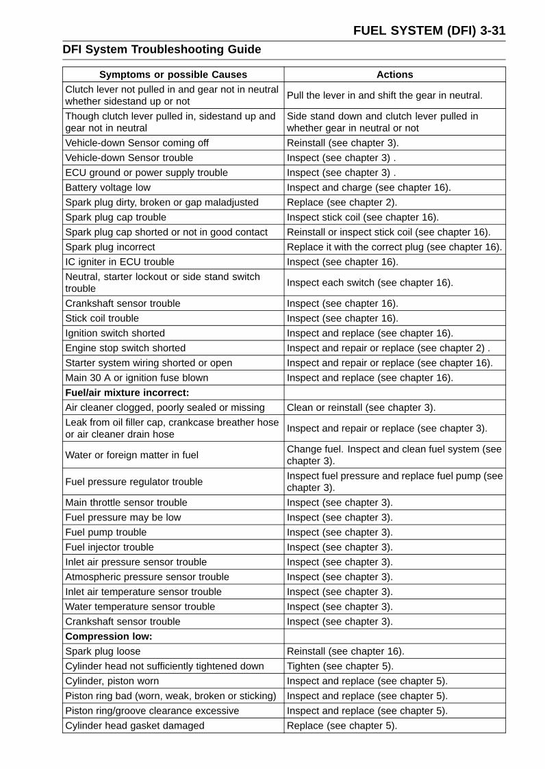
FUEL SYSTEM (DFI) 3-31DFI System Troubleshooting Guide
Symptoms or possible Causes ActionsClutch lever not pulled in and gear not in neutralwhether sidestand up or not
Pull the lever in and shift the gear in neutral.
Though clutch lever pulled in, sidestand up andgear not in neutral
Side stand down and clutch lever pulled inwhether gear in neutral or not
Vehicle-down Sensor coming off Reinstall (see chapter 3).
Vehicle-down Sensor trouble Inspect (see chapter 3) .
ECU ground or power supply trouble Inspect (see chapter 3) .
Battery voltage low Inspect and charge (see chapter 16).
Spark plug dirty, broken or gap maladjusted Replace (see chapter 2).
Spark plug cap trouble Inspect stick coil (see chapter 16).
Spark plug cap shorted or not in good contact Reinstall or inspect stick coil (see chapter 16).
Spark plug incorrect Replace it with the correct plug (see chapter 16).
IC igniter in ECU trouble Inspect (see chapter 16).
Neutral, starter lockout or side stand switchtrouble
Inspect each switch (see chapter 16).
Crankshaft sensor trouble Inspect (see chapter 16).
Stick coil trouble Inspect (see chapter 16).
Ignition switch shorted Inspect and replace (see chapter 16).
Engine stop switch shorted Inspect and repair or replace (see chapter 2) .
Starter system wiring shorted or open Inspect and repair or replace (see chapter 16).
Main 30 A or ignition fuse blown Inspect and replace (see chapter 16).
Fuel/air mixture incorrect:Air cleaner clogged, poorly sealed or missing Clean or reinstall (see chapter 3).
Leak from oil filler cap, crankcase breather hoseor air cleaner drain hose
Inspect and repair or replace (see chapter 3).
Water or foreign matter in fuelChange fuel. Inspect and clean fuel system (seechapter 3).
Fuel pressure regulator troubleInspect fuel pressure and replace fuel pump (seechapter 3).
Main throttle sensor trouble Inspect (see chapter 3).
Fuel pressure may be low Inspect (see chapter 3).
Fuel pump trouble Inspect (see chapter 3).
Fuel injector trouble Inspect (see chapter 3).
Inlet air pressure sensor trouble Inspect (see chapter 3).
Atmospheric pressure sensor trouble Inspect (see chapter 3).
Inlet air temperature sensor trouble Inspect (see chapter 3).
Water temperature sensor trouble Inspect (see chapter 3).
Crankshaft sensor trouble Inspect (see chapter 3).
Compression low:Spark plug loose Reinstall (see chapter 16).
Cylinder head not sufficiently tightened down Tighten (see chapter 5).
Cylinder, piston worn Inspect and replace (see chapter 5).
Piston ring bad (worn, weak, broken or sticking) Inspect and replace (see chapter 5).
Piston ring/groove clearance excessive Inspect and replace (see chapter 5).
Cylinder head gasket damaged Replace (see chapter 5).
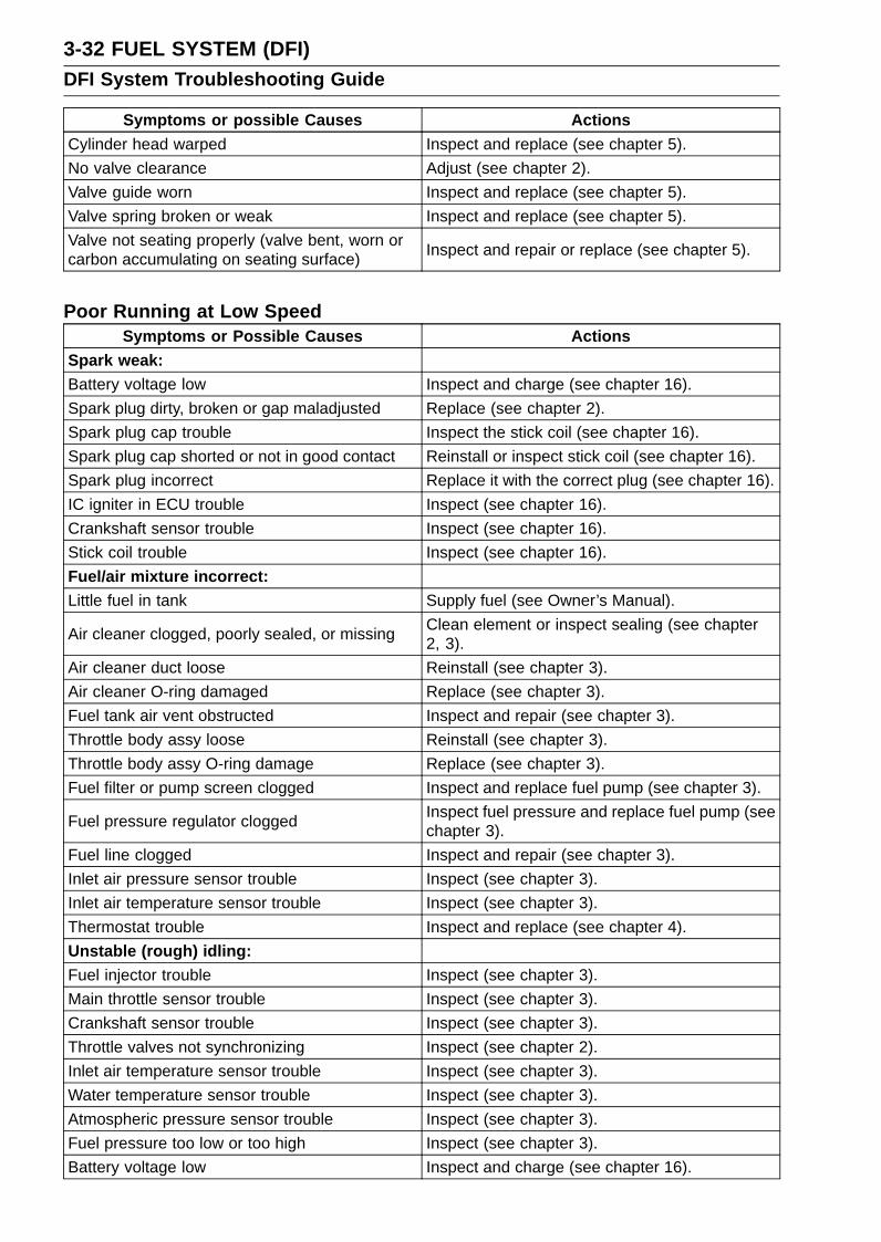
3-32 FUEL SYSTEM (DFI)DFI System Troubleshooting Guide
Symptoms or possible Causes Actions
Cylinder head warped Inspect and replace (see chapter 5).
No valve clearance Adjust (see chapter 2).
Valve guide worn Inspect and replace (see chapter 5).
Valve spring broken or weak Inspect and replace (see chapter 5).
Valve not seating properly (valve bent, worn orcarbon accumulating on seating surface)
Inspect and repair or replace (see chapter 5).
Poor Running at Low SpeedSymptoms or Possible Causes Actions
Spark weak:Battery voltage low Inspect and charge (see chapter 16).
Spark plug dirty, broken or gap maladjusted Replace (see chapter 2).
Spark plug cap trouble Inspect the stick coil (see chapter 16).
Spark plug cap shorted or not in good contact Reinstall or inspect stick coil (see chapter 16).
Spark plug incorrect Replace it with the correct plug (see chapter 16).
IC igniter in ECU trouble Inspect (see chapter 16).
Crankshaft sensor trouble Inspect (see chapter 16).
Stick coil trouble Inspect (see chapter 16).
Fuel/air mixture incorrect:Little fuel in tank Supply fuel (see Owner’s Manual).
Air cleaner clogged, poorly sealed, or missingClean element or inspect sealing (see chapter2, 3).
Air cleaner duct loose Reinstall (see chapter 3).
Air cleaner O-ring damaged Replace (see chapter 3).
Fuel tank air vent obstructed Inspect and repair (see chapter 3).
Throttle body assy loose Reinstall (see chapter 3).
Throttle body assy O-ring damage Replace (see chapter 3).
Fuel filter or pump screen clogged Inspect and replace fuel pump (see chapter 3).
Fuel pressure regulator cloggedInspect fuel pressure and replace fuel pump (seechapter 3).
Fuel line clogged Inspect and repair (see chapter 3).
Inlet air pressure sensor trouble Inspect (see chapter 3).
Inlet air temperature sensor trouble Inspect (see chapter 3).
Thermostat trouble Inspect and replace (see chapter 4).
Unstable (rough) idling:Fuel injector trouble Inspect (see chapter 3).
Main throttle sensor trouble Inspect (see chapter 3).
Crankshaft sensor trouble Inspect (see chapter 3).
Throttle valves not synchronizing Inspect (see chapter 2).
Inlet air temperature sensor trouble Inspect (see chapter 3).
Water temperature sensor trouble Inspect (see chapter 3).
Atmospheric pressure sensor trouble Inspect (see chapter 3).
Fuel pressure too low or too high Inspect (see chapter 3).
Battery voltage low Inspect and charge (see chapter 16).
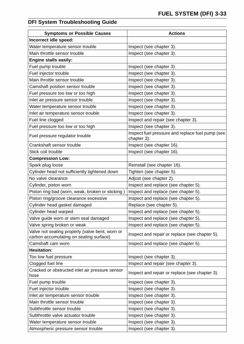
FUEL SYSTEM (DFI) 3-33DFI System Troubleshooting Guide
Symptoms or Possible Causes ActionsIncorrect idle speed:Water temperature sensor trouble Inspect (see chapter 3).
Main throttle sensor trouble Inspect (see chapter 3).
Engine stalls easily:Fuel pump trouble Inspect (see chapter 3).
Fuel injector trouble Inspect (see chapter 3).
Main throttle sensor trouble Inspect (see chapter 3).
Camshaft position sensor trouble Inspect (see chapter 3).
Fuel pressure too low or too high Inspect (see chapter 3).
Inlet air pressure sensor trouble Inspect (see chapter 3).
Water temperature sensor trouble Inspect (see chapter 3).
Inlet air temperature sensor trouble Inspect (see chapter 3).
Fuel line clogged Inspect and repair (see chapter 3).
Fuel pressure too low or too high Inspect (see chapter 3).
Fuel pressure regulator troubleInspect fuel pressure and replace fuel pump (seechapter 3).
Crankshaft sensor trouble Inspect (see chapter 16).
Stick coil trouble Inspect (see chapter 16).
Compression Low:Spark plug loose Reinstall (see chapter 16).
Cylinder head not sufficiently tightened down Tighten (see chapter 5).
No valve clearance Adjust (see chapter 2).
Cylinder, piston worn Inspect and replace (see chapter 5).
Piston ring bad (worn, weak, broken or sticking ) Inspect and replace (see chapter 5).
Piston ring/groove clearance excessive Inspect and replace (see chapter 5).
Cylinder head gasket damaged Replace (see chapter 5).
Cylinder head warped Inspect and replace (see chapter 5).
Valve guide worn or stem seal damaged Inspect and replace (see chapter 5).
Valve spring broken or weak Inspect and replace (see chapter 5).
Valve not seating properly (valve bent, worn orcarbon accumulating on seating surface)
Inspect and repair or replace (see chapter 5).
Camshaft cam worn Inspect and replace (see chapter 5).
Hesitation:Too low fuel pressure Inspect (see chapter 3).
Clogged fuel line Inspect and repair (see chapter 3).
Cracked or obstructed inlet air pressure sensorhose
Inspect and repair or replace (see chapter 3).
Fuel pump trouble Inspect (see chapter 3).
Fuel injector trouble Inspect (see chapter 3).
Inlet air temperature sensor trouble Inspect (see chapter 3).
Main throttle sensor trouble Inspect (see chapter 3).
Subthrottle sensor trouble Inspect (see chapter 3).
Subthrottle valve actuator trouble Inspect (see chapter 3).
Water temperature sensor trouble Inspect (see chapter 3).
Atmospheric pressure sensor trouble Inspect (see chapter 3).
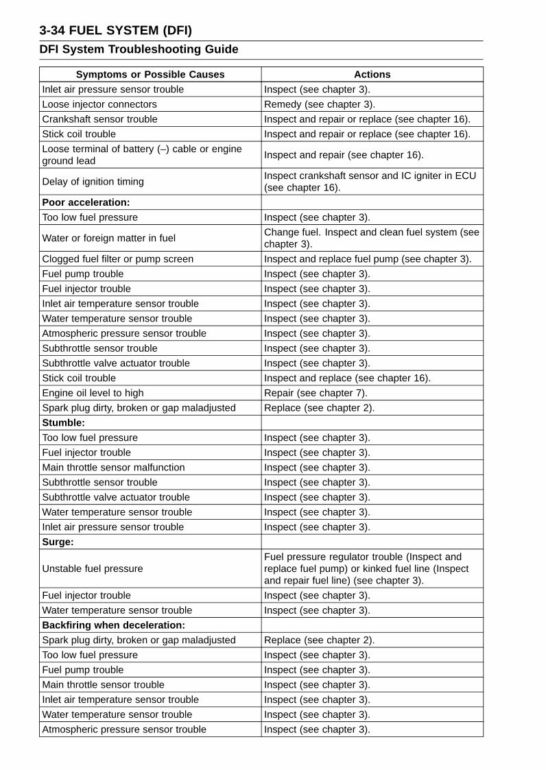
3-34 FUEL SYSTEM (DFI)DFI System Troubleshooting Guide
Symptoms or Possible Causes ActionsInlet air pressure sensor trouble Inspect (see chapter 3).
Loose injector connectors Remedy (see chapter 3).
Crankshaft sensor trouble Inspect and repair or replace (see chapter 16).
Stick coil trouble Inspect and repair or replace (see chapter 16).
Loose terminal of battery (–) cable or engineground lead
Inspect and repair (see chapter 16).
Delay of ignition timingInspect crankshaft sensor and IC igniter in ECU(see chapter 16).
Poor acceleration:
Too low fuel pressure Inspect (see chapter 3).
Water or foreign matter in fuelChange fuel. Inspect and clean fuel system (seechapter 3).
Clogged fuel filter or pump screen Inspect and replace fuel pump (see chapter 3).
Fuel pump trouble Inspect (see chapter 3).
Fuel injector trouble Inspect (see chapter 3).
Inlet air temperature sensor trouble Inspect (see chapter 3).
Water temperature sensor trouble Inspect (see chapter 3).
Atmospheric pressure sensor trouble Inspect (see chapter 3).
Subthrottle sensor trouble Inspect (see chapter 3).
Subthrottle valve actuator trouble Inspect (see chapter 3).
Stick coil trouble Inspect and replace (see chapter 16).
Engine oil level to high Repair (see chapter 7).
Spark plug dirty, broken or gap maladjusted Replace (see chapter 2).
Stumble:
Too low fuel pressure Inspect (see chapter 3).
Fuel injector trouble Inspect (see chapter 3).
Main throttle sensor malfunction Inspect (see chapter 3).
Subthrottle sensor trouble Inspect (see chapter 3).
Subthrottle valve actuator trouble Inspect (see chapter 3).
Water temperature sensor trouble Inspect (see chapter 3).
Inlet air pressure sensor trouble Inspect (see chapter 3).
Surge:
Unstable fuel pressureFuel pressure regulator trouble (Inspect andreplace fuel pump) or kinked fuel line (Inspectand repair fuel line) (see chapter 3).
Fuel injector trouble Inspect (see chapter 3).
Water temperature sensor trouble Inspect (see chapter 3).
Backfiring when deceleration:Spark plug dirty, broken or gap maladjusted Replace (see chapter 2).
Too low fuel pressure Inspect (see chapter 3).
Fuel pump trouble Inspect (see chapter 3).
Main throttle sensor trouble Inspect (see chapter 3).
Inlet air temperature sensor trouble Inspect (see chapter 3).
Water temperature sensor trouble Inspect (see chapter 3).
Atmospheric pressure sensor trouble Inspect (see chapter 3).

FUEL SYSTEM (DFI) 3-35DFI System Troubleshooting Guide
Symptoms or Possible Causes ActionsInlet air pressure sensor trouble Inspect (see chapter 3).
Vacuum switch valve broken Inspect and replace (see chapter 5).
Air suction valve trouble Inspect and replace (see chapter 5).
After fire:Crankshaft sensor trouble Inspect (see chapter 16).
Spark plug burned or gap maladjusted Replace (see chapter 2).
Inlet air temperature sensor trouble Inspect (see chapter 3).
Water temperature sensor trouble Inspect (see chapter 3).
Atmospheric pressure sensor trouble Inspect (see chapter 3).
Inlet air pressure sensor trouble Inspect (see chapter 3).
Fuel injector trouble Inspect (see chapter 3).
Run-on (dieseling):Ignition switch trouble Inspect and replace (see chapter 16).
Engine stop switch trouble Inspect and repair or replace (see chapter 2).
Fuel injector trouble Inspect (see chapter 3).
Loose terminal of battery (–) cable or ECUground lead
Inspect and repair (see chapter 16).
Carbon accumulating on valve seating surface Repair (see chapter 5).
Engine overheating(see Overheating of Troubleshooting Guide, seechapter 17)
Other:Engine oil viscosity too high Change (see chapter 2).
Drive train troubleInspect drive chain (see chapter 2) and sprocket(see chapter 11).
Brake draggingInspect caliper fluid seal damage or cloggingof master cylinder relief and supply ports (seechapter 12).
Clutch slipping Inspect friction plates for wear (see chapter 6).
Engine overheating(see Overheating of Troubleshooting Guide, seechapter 17)
Vacuum switch valve trouble Inspect and replace (see chapter 5).
Air suction valve trouble Inspect and replace (see chapter 5).
Intermittent any DFI fault and its recoveryCheck that DFI connectors are clean and tight,and examine wires for signs of burning or fraying(see chapter 3).
Poor Running or No Power at High Speed:Symptoms or Possible Causes Actions
Firing incorrect:Spark plug dirty, broken or maladjusted Replace (see chapter 2).
Spark plug cap trouble Inspect stick coil (see chapter 16).
Spark plug cap shorted or not in good contact Reinstall or inspect stick coil (see chapter 16).
Spark plug incorrect Replace it with the correct plug (see chapter 16).
IC igniter in ECU trouble Inspect (see chapter 16).
Crankshaft sensor trouble Inspect (see chapter 16).

3-36 FUEL SYSTEM (DFI)DFI System Troubleshooting Guide
Symptoms or Possible Causes Actions
Stick coil trouble Inspect (see chapter 16).
Fuel/air mixture incorrect:Air cleaner clogged, poorly sealed, or missing Clean element or inspect sealing (see chapter 3).
Air cleaner duct loose Reinstall (see chapter 3).
Air cleaner O-ring damaged Replace (see chapter 3).
Water or foreign matter in fuelChange fuel. Inspect and clean fuel system (seechapter 3).
Throttle body assy loose Reinstall (see chapter 3).
Throttle body assy O-ring damaged Replace (see chapter 3).
Fuel tank air vent obstructed Inspect and repair (see chapter 3).
Fuel line clogged Inspect and repair (see chapter 3).
Fuel pump operates intermittently and often DFIfuse blows.
Pump bearings may wear. Replace the pump(see chapter 3).
Fuel pump trouble Inspect (see chapter 3).
Inlet air temperature sensor trouble Inspect (see chapter 3).
Main throttle sensor trouble Inspect (see chapter 3).
Atmospheric pressure sensor trouble Inspect (see chapter 3).
Inlet air pressure sensor trouble Inspect (see chapter 3).
Cracked or obstructed inlet air pressure sensorhose
Inspect and repair or replace (see chapter 3).
Injector clogged Visually inspect and replace (see chapter 3).
Compression low:Spark plug loose Reinstall (see chapter 16).
Cylinder head not sufficiently tightened down Tighten (see chapter 5).
No valve clearance Adjust (see chapter 2).
Cylinder, piston worn Inspect and replace (see chapter 5).
Piston ring bad (worn, weak, broken or sticking) Inspect and replace (see chapter 5).
Piston ring/groove clearance excessive Inspect and replace (see chapter 5).
Cylinder head gasket damaged Replace (see chapter 5) .
Cylinder head warped Inspect and replace (see chapter 5).
Valve spring broken or weak Inspect and replace (see chapter 5).
Valve not seating properly (valve bent , worn orcarbon accumulating on the seating surface)
Inspect and repair or replace (see chapter 5).
Knocking:Carbon built up in combustion chamber Repair (see chapter 5).
Fuel poor quality or incorrect (Use the gasolinerecommended in the Owner’s Manual)
Change fuel (see chapter 3).
Spark plug incorrect Replace it with the correct plug (see chapter 16).
Stick coil trouble Inspect (see chapter 16).
IC igniter in ECU trouble Inspect (see chapter 16).
Inlet air temperature sensor trouble Inspect (see chapter 3).
Atmospheric pressure sensor trouble Inspect (see chapter 3).
Miscellaneous:Subthrottle sensor trouble Inspect (see chapter 3).
Subthrottle valve actuator trouble Inspect (see chapter 3).

FUEL SYSTEM (DFI) 3-37DFI System Troubleshooting Guide
Symptoms or Possible Causes ActionsSpeed sensor trouble Inspect (see chapter 3).
Throttle valves won’t fully openInspect throttle cable and lever linkage (seechapter 3).
Brake draggingInspect caliper fluid seal damage or cloggingof master cylinder relief and supply ports (seechapter 12).
Clutch slipping Inspect friction plates for wear (see chapter 6).
Engine overheating-Water temperature sensor,crankshaft sensor or speed sensor trouble
(see Overheating of Troubleshooting Guide inchapter 17).
Engine oil level too high Repair (see chapter 7).
Engine oil viscosity too high Change (see chapter 2).
Drive train troubleInspect drive chain (see chapter 2) and sprockets(see chapter 11).
Camshaft cam worn Inspect and replace (see chapter 5).
Vacuum switch valve trouble Inspect and replace (see chapter 5).
Air suction valve trouble Inspect and replace (see chapter 5).
Catalytic converters melt down due to muffleroverheating (KLEEN)
Replace muffler (see chapter 5).
Exhaust Smokes Excessively:(White smokes)Piston oil ring worn Inspect and replace (see chapter 5).
Cylinder worn Inspect and replace (see chapter 5).
Valve oil seal damaged Replace (see chapter 5).
Valve guide worn Replace the guide (see chapter 5).
Engine oil level too high Repair (see chapter 7).
(Black smoke)Air cleaner clogged Clean (see chapter 3).
Too high fuel pressure Inspect (see chapter 3) .
Injector stuck open Inspect (see chapter 3).
Water temperature sensor trouble Inspect and replace (see chapter 3).
Inlet air temperature sensor trouble Inspect and replace (see chapter 3).
(Brown smoke)Air cleaner duct loose Reinstall (see chapter 3).
Air cleaner O-ring damaged Replace (see chapter 3).
Too low fuel pressure Inspect fuel line and fuel pump (see chapter 3).
Water temperature sensor trouble Inspect and replace (see chapter 3).
Inlet air temperature sensor trouble Inspect and replace (see chapter 3).
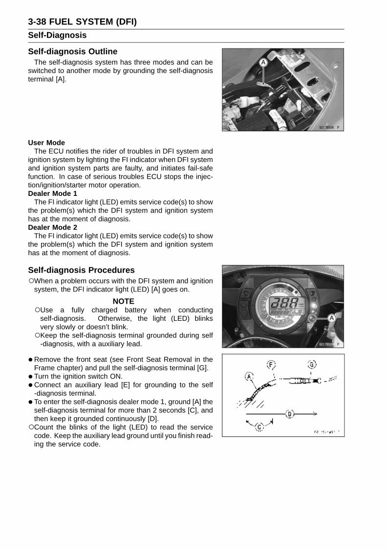
3-38 FUEL SYSTEM (DFI)Self-Diagnosis
Self-diagnosis OutlineThe self-diagnosis system has three modes and can be
switched to another mode by grounding the self-diagnosisterminal [A].
User ModeThe ECU notifies the rider of troubles in DFI system and
ignition system by lighting the FI indicator when DFI systemand ignition system parts are faulty, and initiates fail-safefunction. In case of serious troubles ECU stops the injec-tion/ignition/starter motor operation.Dealer Mode 1
The FI indicator light (LED) emits service code(s) to showthe problem(s) which the DFI system and ignition systemhas at the moment of diagnosis.Dealer Mode 2
The FI indicator light (LED) emits service code(s) to showthe problem(s) which the DFI system and ignition systemhas at the moment of diagnosis.
Self-diagnosis ProceduresWhen a problem occurs with the DFI system and ignition
system, the DFI indicator light (LED) [A] goes on.
NOTEUse a fully charged battery when conducting
self-diagnosis. Otherwise, the light (LED) blinksvery slowly or doesn’t blink.Keep the self-diagnosis terminal grounded during self
-diagnosis, with a auxiliary lead.
•Remove the front seat (see Front Seat Removal in theFrame chapter) and pull the self-diagnosis terminal [G].
• Turn the ignition switch ON.
•Connect an auxiliary lead [E] for grounding to the self-diagnosis terminal.
• To enter the self-diagnosis dealer mode 1, ground [A] theself-diagnosis terminal for more than 2 seconds [C], andthen keep it grounded continuously [D].Count the blinks of the light (LED) to read the service
code. Keep the auxiliary lead ground until you finish read-ing the service code.

FUEL SYSTEM (DFI) 3-39Self-Diagnosis
•To enter the self-diagnosis dealer mode 2 repeat opening[B] and grounding [A] the lead more than five times [F]within 2 seconds [C] after the lead is first grounded, andthen keep it grounded continuously [D] for more than 2seconds.Self-diagnosis Terminal [G]
Count the blinks of the light (LED) to read the servicecode. Keep the auxiliary lead [E] ground until you finishreading the service code.
NOTEIf the self-diagnosis mode is in dealer mode 1 then you
need to enter the dealer mode 2, turn off the ignitionswitch once.
Service Code Clearing Procedures
•Enter the self-diagnosis dealer mode 2 (see Self- diagno-sis Procedures in this chapter).
NOTEMake sure to keep the grounding until the following
opening and grounding starts.
•Pull the clutch lever in more than 5 seconds, and thenrelease it.
• Repeat opening [B] and grounding [A] the lead [E] (self-diagnosis terminal [G]) more than five times [F] within 2seconds [C] after the lead is grounded, and then keep itgrounded continuously [D] for more than 2 seconds.
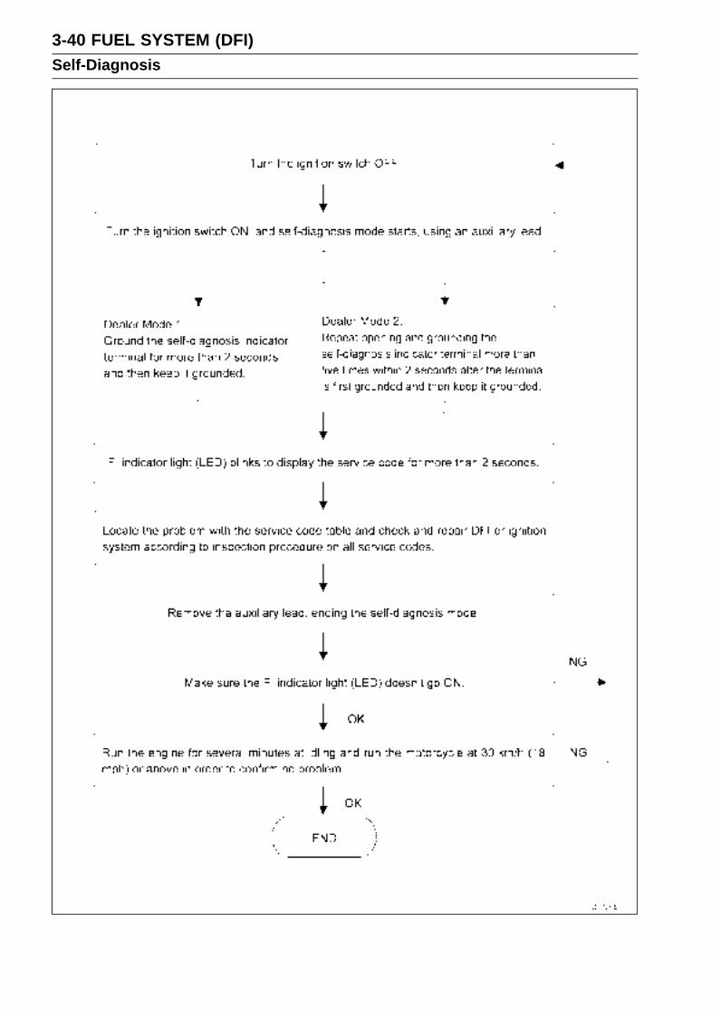
3-40 FUEL SYSTEM (DFI)Self-Diagnosis
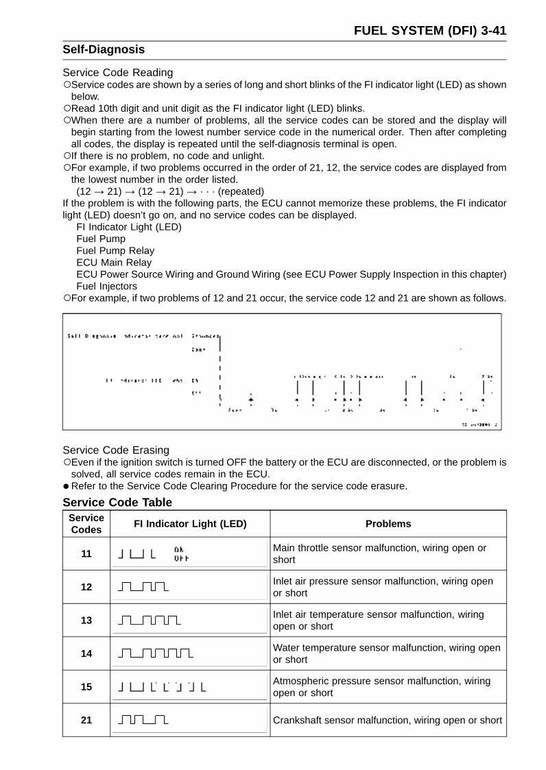
FUEL SYSTEM (DFI) 3-41Self-Diagnosis
Service Code ReadingService codes are shown by a series of long and short blinks of the FI indicator light (LED) as shown
below.Read 10th digit and unit digit as the FI indicator light (LED) blinks.When there are a number of problems, all the service codes can be stored and the display will
begin starting from the lowest number service code in the numerical order. Then after completingall codes, the display is repeated until the self-diagnosis terminal is open.If there is no problem, no code and unlight.For example, if two problems occurred in the order of 21, 12, the service codes are displayed from
the lowest number in the order listed.(12 → 21) → (12 → 21) → · · · (repeated)
If the problem is with the following parts, the ECU cannot memorize these problems, the FI indicatorlight (LED) doesn’t go on, and no service codes can be displayed.
FI Indicator Light (LED)Fuel PumpFuel Pump RelayECU Main RelayECU Power Source Wiring and Ground Wiring (see ECU Power Supply Inspection in this chapter)Fuel Injectors
For example, if two problems of 12 and 21 occur, the service code 12 and 21 are shown as follows.
Service Code ErasingEven if the ignition switch is turned OFF the battery or the ECU are disconnected, or the problem is
solved, all service codes remain in the ECU.
•Refer to the Service Code Clearing Procedure for the service code erasure.
Service Code TableServiceCodes
FI Indicator Light (LED) Problems
11 Main throttle sensor malfunction, wiring open orshort
12 Inlet air pressure sensor malfunction, wiring openor short
13 Inlet air temperature sensor malfunction, wiringopen or short
14 Water temperature sensor malfunction, wiring openor short
15 Atmospheric pressure sensor malfunction, wiringopen or short
21 Crankshaft sensor malfunction, wiring open or short

3-42 FUEL SYSTEM (DFI)Self-Diagnosis
ServiceCodes FI Indicator Light (LED) Problems
23 Camshaft position sensor malfunction, wiring openor short
24 Speed sensor malfunction
31 Vehicle-down sensor malfunction, wiring open orshort
32 Subthrottle sensor malfunction, wiring open or short
34 Exhaust butterfly valve sensor malfunction, wiringopen or short
35 Immobilizer amplifier malfunction
36 Blank key detection
51 Stick (Ignition) coil #1 malfunction, wiring open orshort
52 Stick (Ignition) coil #2 malfunction, wiring open orshort
53Stick (Ignition) coil #3 malfunction, wiring open orshort
54 Stick (Ignition) coil #4 malfunction, wiring open orshort
62 Subthrottle valve actuator malfunction, wiring openor short
63 Exhaust butterfly valve actuator malfunction, wiringopen or short
Notes:The ECU may be involved in these problems. If all the parts and circuits checked out good, be sure
to check the ECU for ground and power supply. If the ground and power supply are checked good,replace the ECU.When no service code is displayed, the electrical parts of the DFI system has no fault, and the
mechanical parts of the DFI system and the engine are suspect.

FUEL SYSTEM (DFI) 3-43Self-Diagnosis
BackupsThe ECU takes the following measures to prevent engine damage when the DFI or the ignition
system parts have troubles.
ServiceCodes
Parts Output Signal UsableRange or Criteria Backups by ECU
11 Main ThrottleSensor
Main Throttle SensorOutput Voltage1.02 ∼ 4.62 V
If the main throttle sensor system fails (thesignal is out of the usable range, wiring shortor open), the ECU locks ignition timing into theignition timing at closed throttle position andsets the DFI in the D-J method.
12Inlet AirPressureSensor
Inlet Air Pressure(absolute)Pv = 100 mmHg ∼ 900mmHg
If the inlet air pressure sensor system fails (thesignal Pv is out of the usable range, wiringshort or open), the ECU sets the DFI in the α -N method (1).
13Inlet Air
TemperatureSensor
Inlet Air TemperatureTa = – 47°C ∼ + 178°C
If the inlet air temperature sensor fails (thesignal is out of the usable range, wiring shortor open), the ECU sets Ta at 30°C.
14Water
TemperatureSensor
Water TemperatureTw = – 30C° ∼ + 120°C
If the water temperature sensor system fails(the signal is out of the usable range, wiringshort or open), the ECU sets Tw at 80°C.
15Atmospheric
PressureSensor
Absolute AtmosphericPressurePa = 100 mmHg ∼ 900mmHg
If the atmospheric pressure sensor systemfails (the signal is out of the usable range,wiring short or open), the ECU sets Pa at 760mmHg (the standard atmospheric pressure).
21 CrankshaftSensor
Crankshaft sensor mustsend 23 signals (outputsignal) to the ECU at theone cranking.
If crankshaft sensor generates less than 23 ormore signals, the engine stops by itself.
23CamshaftPositionSensor
Camshaft position sensormust send one signals(output signal) to the ECUat the two crankings.
If the camshaft position sensor system fails(the signal is missing, wiring short or open),the ECU continues to ignite cylinders in thesame sequence following the last good signal.
24 SpeedSensor
Speed Sensor must send4 signals (output signal) tothe ECU at the one rotationof the drive shaft
If the speed sensor system fails (no signal,wiring short or open), the speedometer shows0.
31Vehicle-downSensor
Vehicle-down SensorOutput Voltage (signal)Vd = 0.2 ∼ 4.8 V
If the vehicle-down sensor system has failures(the output voltage Vd is more than usablerange, wiring open), the ECU shuts off thefuel pump, the fuel injectors and the ignitionsystem.
32 SubthrottleSensor
Subthrottle Sensor OutputVoltage0.2 ∼ 4.8 V
If the subthrottle sensor system fails (thesignal is out of the usable range, wiring shortor open), the actuator locks subthrottle valveat full open position.
34
ExhaustButterfly
ValveActuatorSensor
Exhaust Butterfly ValveActuator Sensor OutputVoltage0.2 ∼ 4.8 V
If the exhaust butterfly valve system fails (thesignal is out of the usable range, wiring shortor open), the actuator locks exhaust butterflyvalve at full open position.
35 ImmobilizerAmplifier
–If the immobilizer system fails (no signal, wiringshort or open), the vehicle is no start and run.
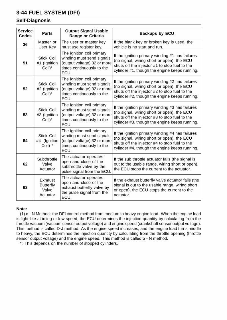
3-44 FUEL SYSTEM (DFI)Self-Diagnosis
ServiceCodes Parts
Output Signal UsableRange or Criteria Backups by ECU
36 Master orUser Key
The user or master keymust use register key.
If the blank key or broken key is used, thevehicle is no start and run.
51Stick Coil
#1 (IgnitionCoil)*
The ignition coil primarywinding must send signals(output voltage) 32 or moretimes continuously to theECU.
If the ignition primary winding #1 has failures(no signal, wiring short or open), the ECUshuts off the injector #1 to stop fuel to thecylinder #1, though the engine keeps running.
52Stick Coil
#2 (IgnitionCoil)*
The ignition coil primarywinding must send signals(output voltage) 32 or moretimes continuously to theECU.
If the ignition primary winding #2 has failures(no signal, wiring short or open), the ECUshuts off the injector #2 to stop fuel to thecylinder #2, though the engine keeps running.
53Stick Coil
#3 (IgnitionCoil)*
The ignition coil primarywinding must send signals(output voltage) 32 or moretimes continuously to theECU.
If the ignition primary winding #3 has failures(no signal, wiring short or open), the ECUshuts off the injector #3 to stop fuel to thecylinder #3, though the engine keeps running.
54Stick Coil
#4 (IgnitionCoil) *
The ignition coil primarywinding must send signals(output voltage) 32 or moretimes continuously to theECU.
If the ignition primary winding #4 has failures(no signal, wiring short or open), the ECUshuts off the injector #4 to stop fuel to thecylinder #4, though the engine keeps running.
62Subthrottle
ValveActuator
The actuator operatesopen and close of thesubthrottle valve by thepulse signal from the ECU.
If the sub throttle actuator fails (the signal isout to the usable range, wiring short or open),the ECU stops the current to the actuator.
63
ExhaustButterfly
ValveActuator
The actuator operatesopen and close of theexhaust butterfly valve bythe pulse signal from theECU.
If the exhaust butterfly valve actuator fails (thesignal is out to the usable range, wiring shortor open), the ECU stops the current to theactuator.
Note:(1) α - N Method: the DFI control method from medium to heavy engine load. When the engine load
is light like at idling or low speed, the ECU determines the injection quantity by calculating from thethrottle vacuum (vacuum sensor output voltage) and engine speed (crankshaft sensor output voltage).This method is called D-J method. As the engine speed increases, and the engine load turns middleto heavy, the ECU determines the injection quantity by calculating from the throttle opening (throttlesensor output voltage) and the engine speed. This method is called α - N method.
*: This depends on the number of stopped cylinders.

FUEL SYSTEM (DFI) 3-45Main Throttle Sensor (Service Code 11)
The main throttle sensor is a rotating variable resistor thatchanges output voltage according to throttle operating. TheECU senses this voltage change and determines fuel injec-tion quantity, and ignition timing according to engine rpm,and throttle opening.
Input Terminal [A]Output Terminal [B]Ground Terminal [C]
Main Throttle Sensor Removal/Adjustment
CAUTION
Do not remove or adjust the main throttle sensorsince it has been adjusted and set with precision atthe factory.Never drop the throttle body assy, especially on ahard surface. Such a shock to the sensor can dam-age it.
Main Throttle Sensor Connector [A]
Input Voltage Inspection
NOTEBe sure the battery is fully charged.
•Turn the ignition switch OFF.
•Remove the ECU (see ECU Removal in this chapter). Donot disconnect the ECU connectors.
•Connect a digital voltmeter [A] to the connectors [B], usingthe needle adapter set.
Special Tool - Needle Adapter Set: 57001-1457
Main Throttle Sensor Input VoltageConnections to ECU Connector
Meter (+) → BL lead (terminal 10)Meter (–) → BR/BK lead (terminal 28)
•Measure the input voltage with the engine stopped, andwith the connectors joined.
• Turn the ignition switch ON.
Input Voltage at ECU ConnectorStandard: DC 4.75 ∼ 5.25 V
•Turn the ignition switch OFF.If the reading of input voltage is less than the standard,check the ECU for its ground, power supply and wiringshorted.If the input voltage is within the standard range, check theinput voltage at the main throttle sensor connector.
• Remove the throttle body assy temporarily (see ThrottleBody Assy Removal in this chapter).

3-46 FUEL SYSTEM (DFI)Main Throttle Sensor (Service Code 11)
•Disconnect the main throttle sensor connector and con-nect the harness adapter [A] between the harness con-nector and main throttle sensor connector.
• Connect a digital meter to the harness adapter leads.Special Tool - Throttle Sensor Setting Adapter: 57001
-1538
Main Throttle Sensor Input VoltageConnections to Sensor
Meter (+)→ BL leadMeter (–)→ BR/BK lead
• Install the throttle body assy (see Throttle Body Assy In-stallation in this chapter).
•Measure the sensor input voltage with the enginestopped, and with the connector joined.
• Turn the ignition switch ON.
Input Voltage at SensorStandard: DC 4.75 ∼ 5.25 V
•Turn the ignition switch OFF.If the reading is out of the range, check the wiring (seewiring diagram in this section).If the reading is good, check the output voltage of thesensor.
Output Voltage Inspection•Measure the output voltage at the ECU in the same way
as input voltage inspection.Digital Voltmeter [A]Connectors [B]
Special Tool - Needle Adapter Set: 57001-1457
Main Throttle Sensor Output VoltageConnections to ECU
Meter (+) → Y/W lead (terminal 7)Meter (–) → BR/BK lead (terminal 28)
•Start the engine and warm it up thoroughly.
•Check idle speed to ensure throttle opening is correct.
Idle SpeedStandard: 1 300 r/min (rpm)
If the idle speed is out of the specified range, adjust theidle speed (see Idle Speed Adjustment in the PeriodicMaintenance chapter).
• Turn the ignition switch OFF.
•Measure the output voltage with the engine stopped, andwith the connector joined.
• Turn the ignition switch ON.
•Measure the output voltage when the throttle is fullyopened or completely closed.
Output Voltage at ECUStandard: DC 1.02 ∼ 4.62 V (at idle throttle opening to
full throttle opening)
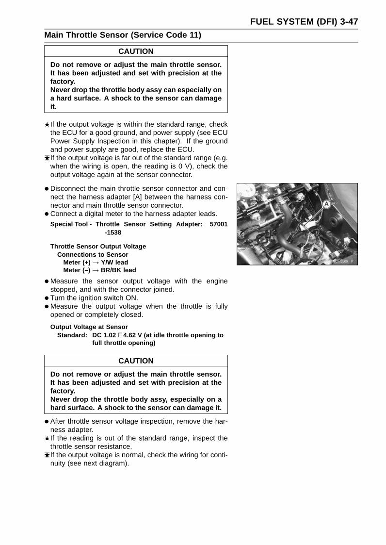
FUEL SYSTEM (DFI) 3-47Main Throttle Sensor (Service Code 11)
CAUTION
Do not remove or adjust the main throttle sensor.It has been adjusted and set with precision at thefactory.Never drop the throttle body assy can especially ona hard surface. A shock to the sensor can damageit.
If the output voltage is within the standard range, checkthe ECU for a good ground, and power supply (see ECUPower Supply Inspection in this chapter). If the groundand power supply are good, replace the ECU.If the output voltage is far out of the standard range (e.g.when the wiring is open, the reading is 0 V), check theoutput voltage again at the sensor connector.
• Disconnect the main throttle sensor connector and con-nect the harness adapter [A] between the harness con-nector and main throttle sensor connector.
• Connect a digital meter to the harness adapter leads.Special Tool - Throttle Sensor Setting Adapter: 57001
-1538
Throttle Sensor Output VoltageConnections to Sensor
Meter (+) → Y/W leadMeter (–) → BR/BK lead
•Measure the sensor output voltage with the enginestopped, and with the connector joined.
• Turn the ignition switch ON.
•Measure the output voltage when the throttle is fullyopened or completely closed.
Output Voltage at SensorStandard: DC 1.02 ∼ 4.62 V (at idle throttle opening to
full throttle opening)
CAUTION
Do not remove or adjust the main throttle sensor.It has been adjusted and set with precision at thefactory.Never drop the throttle body assy, especially on ahard surface. A shock to the sensor can damage it.
•After throttle sensor voltage inspection, remove the har-ness adapter.If the reading is out of the standard range, inspect thethrottle sensor resistance.If the output voltage is normal, check the wiring for conti-nuity (see next diagram).
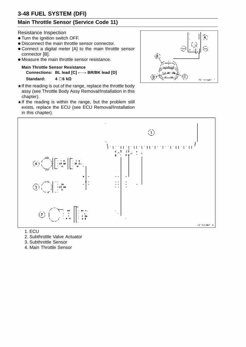
3-48 FUEL SYSTEM (DFI)Main Throttle Sensor (Service Code 11)
Resistance Inspection•Turn the ignition switch OFF.
•Disconnect the main throttle sensor connector.
• Connect a digital meter [A] to the main throttle sensorconnector [B].
•Measure the main throttle sensor resistance.
Main Throttle Sensor ResistanceConnections: BL lead [C] ←→ BR/BK lead [D]
Standard: 4 ∼ 6 kΩ
If the reading is out of the range, replace the throttle bodyassy (see Throttle Body Assy Removal/Installation in thischapter).If the reading is within the range, but the problem stillexists, replace the ECU (see ECU Removal/Installationin this chapter).
1. ECU2. Subthrottle Valve Actuator3. Subthrottle Sensor4. Main Throttle Sensor

FUEL SYSTEM (DFI) 3-49Inlet Air Pressure Sensor (Service Code 12)
CAUTION
Never drop the sensor, especially on a hard surface.Such a shock to the part can damage it.
Removal•Turn the ignition switch OFF.
•Remove:Air Cleaner Housing (see Air Cleaner Housing Removalin this chapter)Inlet Air Pressure Sensor Connector [A]Inlet Air Pressure Sensor [B]Vacuum Hose [C]
Installation
NOTEThe inlet air pressure sensor is the same part as the at-
mospheric sensor except that the sensor has a vacuumhose and different wiring.
• Install:Vacuum Hose
•Put the inlet air pressure sensor in the stay plate [A] ofthrottle body assy.
Input Voltage Inspection
NOTEBe sure the battery is fully charged.The inspection is the same as “Input Voltage Inspection”
of the throttle sensor and the atmospheric pressure sen-sor.
•Turn the ignition switch OFF.
•Remove the ECU (see ECU Removal in this chapter). Donot disconnect the ECU connectors.
•Connect a digital voltmeter [A] to the connector [B], withthe needle adapter set.Special Tool - Needle Adapter Set: 57001-1457
Inlet Air Pressure Sensor Input VoltageConnections to ECU
Meter (+) → BL lead (terminal 10)Meter (–) → BR/BK lead (terminal 28)
•Measure the input voltage with the engine stopped, andwith the connectors joined.
• Turn the ignition switch ON.
Input Voltage at ECUStandard: DC 4.75 ∼ 5.25 V
If the reading is less than the standard range, checkthe ECU for its ground, and power supply (see ECUPower Supply Inspection in this chapter). If the groundand power supply are good, replace the ECU (see ECURemoval/Installation in this chapter).
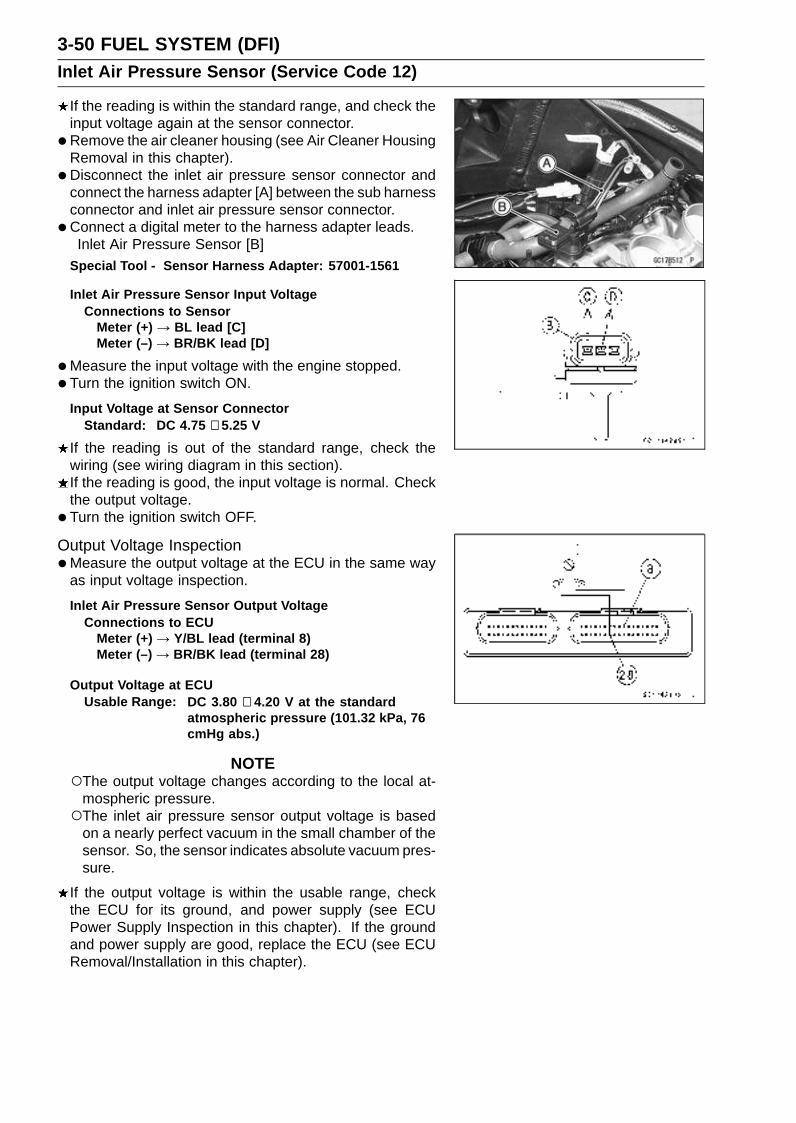
3-50 FUEL SYSTEM (DFI)Inlet Air Pressure Sensor (Service Code 12)
If the reading is within the standard range, and check theinput voltage again at the sensor connector.
• Remove the air cleaner housing (see Air Cleaner HousingRemoval in this chapter).
• Disconnect the inlet air pressure sensor connector andconnect the harness adapter [A] between the sub harnessconnector and inlet air pressure sensor connector.
• Connect a digital meter to the harness adapter leads.Inlet Air Pressure Sensor [B]
Special Tool - Sensor Harness Adapter: 57001-1561
Inlet Air Pressure Sensor Input VoltageConnections to Sensor
Meter (+) → BL lead [C]Meter (–) → BR/BK lead [D]
•Measure the input voltage with the engine stopped.
• Turn the ignition switch ON.
Input Voltage at Sensor ConnectorStandard: DC 4.75 ∼ 5.25 V
If the reading is out of the standard range, check thewiring (see wiring diagram in this section).If the reading is good, the input voltage is normal. Checkthe output voltage.
• Turn the ignition switch OFF.
Output Voltage Inspection•Measure the output voltage at the ECU in the same way
as input voltage inspection.
Inlet Air Pressure Sensor Output VoltageConnections to ECU
Meter (+) → Y/BL lead (terminal 8)Meter (–) → BR/BK lead (terminal 28)
Output Voltage at ECUUsable Range: DC 3.80 ∼ 4.20 V at the standard
atmospheric pressure (101.32 kPa, 76cmHg abs.)
NOTEThe output voltage changes according to the local at-
mospheric pressure.The inlet air pressure sensor output voltage is based
on a nearly perfect vacuum in the small chamber of thesensor. So, the sensor indicates absolute vacuum pres-sure.
If the output voltage is within the usable range, checkthe ECU for its ground, and power supply (see ECUPower Supply Inspection in this chapter). If the groundand power supply are good, replace the ECU (see ECURemoval/Installation in this chapter).
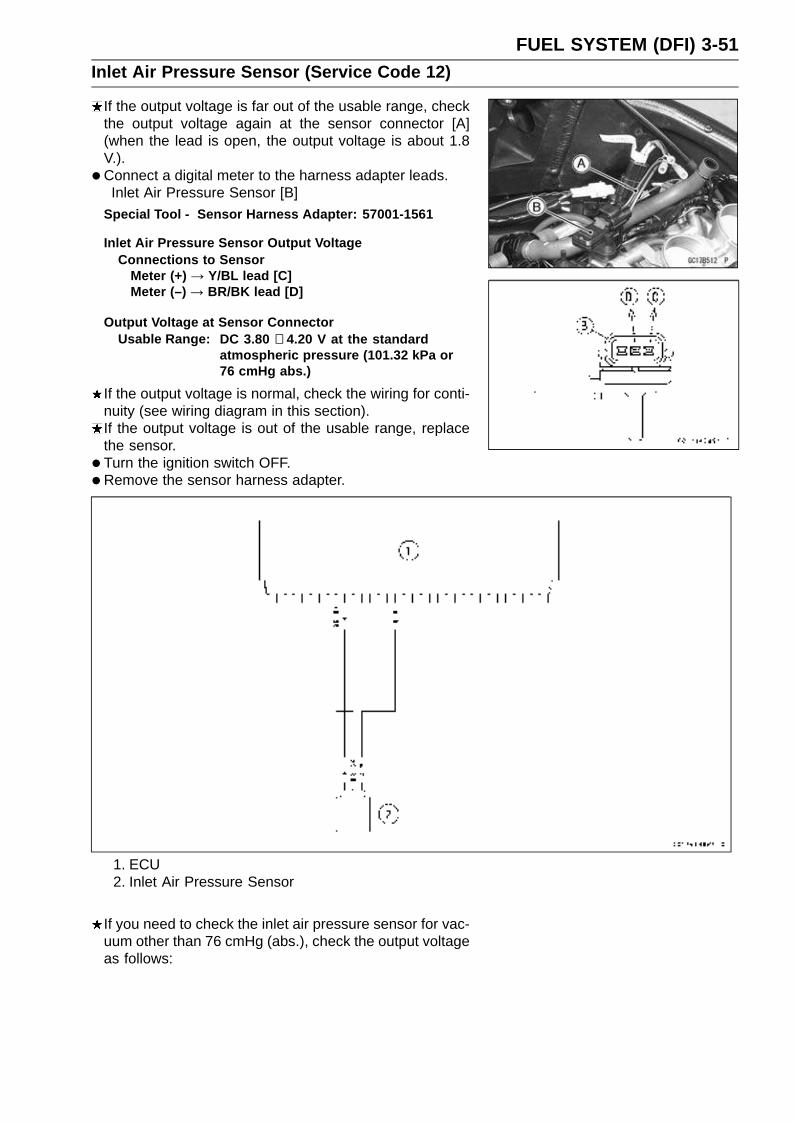
FUEL SYSTEM (DFI) 3-51Inlet Air Pressure Sensor (Service Code 12)
If the output voltage is far out of the usable range, checkthe output voltage again at the sensor connector [A](when the lead is open, the output voltage is about 1.8V.).
• Connect a digital meter to the harness adapter leads.Inlet Air Pressure Sensor [B]
Special Tool - Sensor Harness Adapter: 57001-1561
Inlet Air Pressure Sensor Output VoltageConnections to Sensor
Meter (+) → Y/BL lead [C]Meter (–) → BR/BK lead [D]
Output Voltage at Sensor ConnectorUsable Range: DC 3.80 ∼ 4.20 V at the standard
atmospheric pressure (101.32 kPa or76 cmHg abs.)
If the output voltage is normal, check the wiring for conti-nuity (see wiring diagram in this section).If the output voltage is out of the usable range, replacethe sensor.
• Turn the ignition switch OFF.
•Remove the sensor harness adapter.
1. ECU2. Inlet Air Pressure Sensor
If you need to check the inlet air pressure sensor for vac-uum other than 76 cmHg (abs.), check the output voltageas follows:

3-52 FUEL SYSTEM (DFI)Inlet Air Pressure Sensor (Service Code 12)
•Remove the inlet air pressure sensor [A] and disconnectthe vacuum hose from the sensor.Do not disconnect the sensor connector.
• Connect an auxiliary hose [B] to the inlet air pressure sen-sor.
• Temporarily install the inlet air pressure sensor.Connect a commercially available digital meter [C], vac-
uum gauge [D], and the fork oil level gauge [E] to the inletair pressure sensor.Special Tools - Fork Oil Level Gauge: 57001-1290
Sensor Harness Adapter: 57001-1561
Inlet Air Pressure Sensor Output Voltage Connection toSensor
Meter (+) → Y/BL lead
Meter (–) → BR/BK lead
Turn the ignition switch ON.Measure the inlet air pressure sensor output voltage from
various vacuum readings, while pulling the handle of thefork oil level gauge.Check the inlet air pressure sensor output voltage, using
the following formula and chart.Suppose:Pg : Vacuum Pressure (gauge) of Throttle AssyPl : Local Atmospheric Pressure (absolute) measured by
a barometerPv : Vacuum Pressure (absolute) of Throttle AssyVv : Sensor Output Voltage (V)
thenPv = Pl – Pg
For example, suppose the following data is obtained:Pg = 8 cmHg (vacuum gauge reading)Pl = 70 cmHg (barometer reading)Vv = 3.2 V (digital volt meter reading)
thenPv = 70 – 8 = 62 cmHg (abs.)
Plot this Pv (62 cmHg) at a point [1] on the chart and draw avertical line through the point. Then, you can get the usablerange [2] of the sensor output voltage.
Usable range = 3.08 ∼ 3.48 VPlot Vv (3.2 V) on the vertical line. → Point [3].Results: In the chart, Vv is within the usable range andthe sensor is normal.

FUEL SYSTEM (DFI) 3-53Inlet Air Pressure Sensor (Service Code 12)
ID: IdlingPs: Standard Atmospheric Pressure (Absolute)Pv: Throttle Vacuum Pressure (Absolute)ST: Standard of Sensor Output Voltage (V)TO: Throttle Full OpenUR: Usable Range of Sensor Output Voltage (V)Vv: Inlet Air Pressure Sensor Output Voltage (V) (Digital Meter Reading)
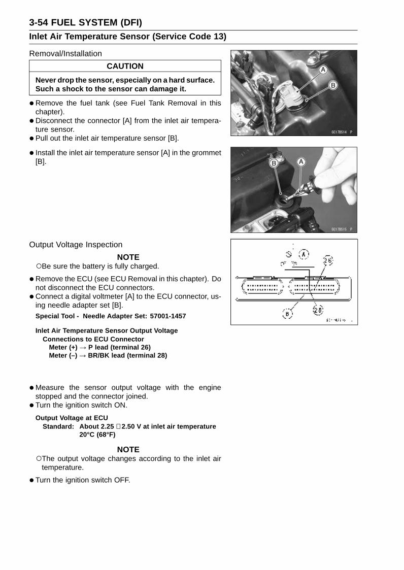
3-54 FUEL SYSTEM (DFI)Inlet Air Temperature Sensor (Service Code 13)
Removal/Installation
CAUTION
Never drop the sensor, especially on a hard surface.Such a shock to the sensor can damage it.
•Remove the fuel tank (see Fuel Tank Removal in thischapter).
• Disconnect the connector [A] from the inlet air tempera-ture sensor.
• Pull out the inlet air temperature sensor [B].
• Install the inlet air temperature sensor [A] in the grommet[B].
Output Voltage Inspection
NOTEBe sure the battery is fully charged.
•Remove the ECU (see ECU Removal in this chapter). Donot disconnect the ECU connectors.
•Connect a digital voltmeter [A] to the ECU connector, us-ing needle adapter set [B].Special Tool - Needle Adapter Set: 57001-1457
Inlet Air Temperature Sensor Output VoltageConnections to ECU Connector
Meter (+) → P lead (terminal 26)Meter (–) → BR/BK lead (terminal 28)
•Measure the sensor output voltage with the enginestopped and the connector joined.
• Turn the ignition switch ON.
Output Voltage at ECUStandard: About 2.25 ∼ 2.50 V at inlet air temperature
20°C (68°F)
NOTEThe output voltage changes according to the inlet air
temperature.
•Turn the ignition switch OFF.
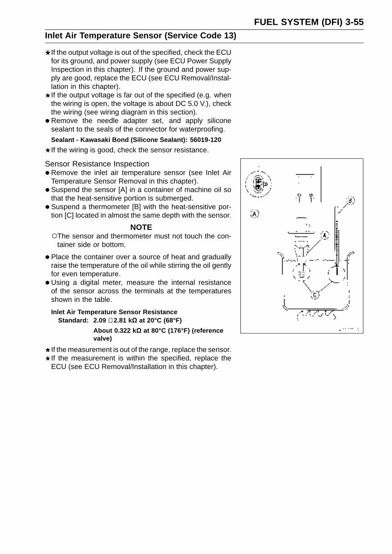
FUEL SYSTEM (DFI) 3-55Inlet Air Temperature Sensor (Service Code 13)
If the output voltage is out of the specified, check the ECUfor its ground, and power supply (see ECU Power SupplyInspection in this chapter). If the ground and power sup-ply are good, replace the ECU (see ECU Removal/Instal-lation in this chapter).If the output voltage is far out of the specified (e.g. whenthe wiring is open, the voltage is about DC 5.0 V.), checkthe wiring (see wiring diagram in this section).
• Remove the needle adapter set, and apply siliconesealant to the seals of the connector for waterproofing.Sealant - Kawasaki Bond (Silicone Sealant): 56019-120
If the wiring is good, check the sensor resistance.
Sensor Resistance Inspection•Remove the inlet air temperature sensor (see Inlet Air
Temperature Sensor Removal in this chapter).
• Suspend the sensor [A] in a container of machine oil sothat the heat-sensitive portion is submerged.
• Suspend a thermometer [B] with the heat-sensitive por-tion [C] located in almost the same depth with the sensor.
NOTEThe sensor and thermometer must not touch the con-
tainer side or bottom.
•Place the container over a source of heat and graduallyraise the temperature of the oil while stirring the oil gentlyfor even temperature.
•Using a digital meter, measure the internal resistanceof the sensor across the terminals at the temperaturesshown in the table.
Inlet Air Temperature Sensor ResistanceStandard: 2.09 ∼ 2.81 kΩ at 20°C (68°F)
About 0.322 kΩ at 80°C (176°F) (referencevalve)
If the measurement is out of the range, replace the sensor.If the measurement is within the specified, replace theECU (see ECU Removal/Installation in this chapter).
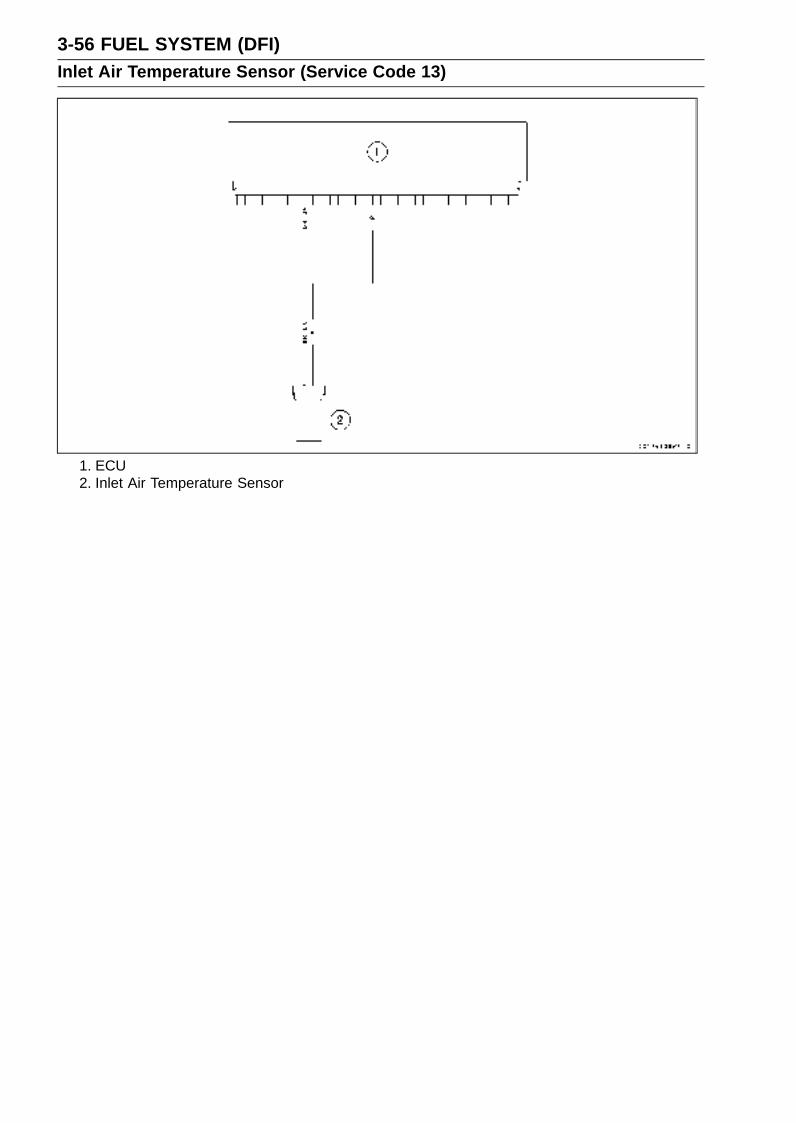
3-56 FUEL SYSTEM (DFI)Inlet Air Temperature Sensor (Service Code 13)
1. ECU2. Inlet Air Temperature Sensor

FUEL SYSTEM (DFI) 3-57Water Temperature Sensor (Service Code 14)
Removal/Installation
CAUTION
Never drop the sensor, especially on a hard surface.Such a shock to the sensor can damage it.
•Drain the coolant (see Coolant Change in the PeriodicMaintenance chapter).
• Remove the throttle body assy (see Throttle Body AssyRemoval in this chapter).
• Remove:ConnectorWater Temperature Sensor [A]
• Apply silicone sealant to the threads of the water temper-ature sensor and tighten it.Sealant - Kawasaki Bond (Silicone Sealant): 56019-120
Torque - Water Temperature Sensor: 25 N·m (2.5 kgf·m, 18ft·lb)
•Fill the engine with coolant and bleed the air from thecooling system (see Coolant Filling in the Cooling Systemchapter).
Output Voltage Inspection
NOTEBe sure the battery is fully charged.
•Remove the ECU (see ECU Removal in this chapter). Donot disconnect the connectors.
•Connect a digital voltmeter [A] to the ECU connectors [B],with the needle adapter set.Special Tool - Needle Adapter Set: 57001-1457
Water Temperature Sensor Output VoltageConnections to ECU
Meter (+) → O lead (terminal 9)Meter (–) → BR/BK lead (terminal 28)
•Measure the sensor output voltage with the enginestopped and the connector joined.
• Turn the ignition switch ON.
Output Voltage at ECUStandard: About 2.80 ∼ 2.97 V at 20°C (68°F)
NOTEThe output voltage changes according to the coolant
temperature in the engine.

3-58 FUEL SYSTEM (DFI)Water Temperature Sensor (Service Code 14)
•Turn the ignition switch OFF.If the output voltage is out of the specified, check the ECUfor its ground, and power supply (see ECU Power SupplyInspection in this chapter). If the ground and power sup-ply are good, replace the ECU (see ECU Removal/Instal-lation in this chapter).If the output voltage is far out of the specified (e.g. whenthe wiring is open, the voltage is about 5 V.), check thewiring (see wiring diagram in this section).If the wiring is good, check the water temperature sensorresistance.
•Remove the needle adapter set, and apply siliconesealant to the seals of the connector for waterproofing.Sealant - Kawasaki Bond (Silicone Sealant): 56019-120
1. ECU2. Meter Unit3. Water Temperature Sensor
Sensor Resistance Inspection•Remove the water temperature sensor (see Removal/In-
stallation in this chapter).
• Refer to the Electrical System chapter for water temper-ature sensor inspection.

FUEL SYSTEM (DFI) 3-59Atmospheric Pressure Sensor (Service Code 15)
CAUTION
Never drop the sensor, especially on a hard surface.Such a shock to the sensor can damage it.
Removal•Turn the ignition switch OFF.
•Remove:Air Cleaner Housing (see Air Cleaner Housing Removalin this chapter)Atmospheric Pressure Sensor Connector [A]Damper [B]Atmospheric Pressure Sensor [C]
Installation
NOTEThe atmospheric pressure sensor is the same part as
the inlet air pressure sensor except that the inlet airpressure sensor has a inlet air pressure hose and dif-ferent wiring.
•Put the atmospheric pressure sensor in the stay plate ofthrottle body assy.
Input Voltage Inspection
NOTEBe sure the battery is fully charged.The inspection is the same as “Input Voltage Inspection”
of the throttle sensor and the inlet air pressure sensor.
•Turn the ignition switch OFF.
•Remove the ECU (see ECU Removal in this chapter). Donot disconnect the ECU connectors.
•Connect a digital voltmeter [A] to the connector [B], withthe needle adapter set.Special Tool - Needle Adapter Set: 57001-1457
Atmospheric Pressure Sensor Input VoltageConnections to ECU
Meter (+) → BL lead (terminal 10)Meter (–) → BR/BK lead (terminal 28)
•Measure the input voltage with the engine stopped, andwith the connectors joined.
• Turn the ignition switch ON.
Input Voltage at ECUStandard: DC 4.75 ∼ 5.25 V
If the reading of input voltage is less than the standardrange, check the ECU for its ground, and power supply(see ECU Power Supply Inspection in this chapter). If theground and power supply are good, replace the ECU (seeECU Removal/Installation in this chapter).
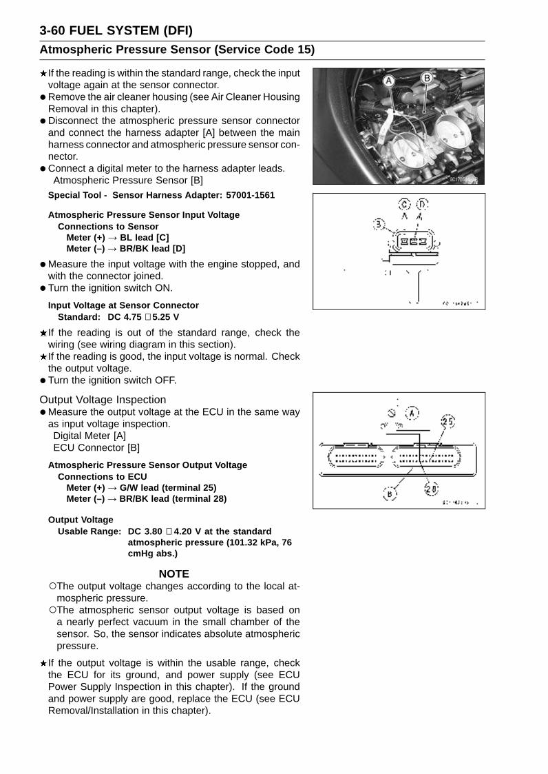
3-60 FUEL SYSTEM (DFI)Atmospheric Pressure Sensor (Service Code 15)
If the reading is within the standard range, check the inputvoltage again at the sensor connector.
• Remove the air cleaner housing (see Air Cleaner HousingRemoval in this chapter).
• Disconnect the atmospheric pressure sensor connectorand connect the harness adapter [A] between the mainharness connector and atmospheric pressure sensor con-nector.
• Connect a digital meter to the harness adapter leads.Atmospheric Pressure Sensor [B]
Special Tool - Sensor Harness Adapter: 57001-1561
Atmospheric Pressure Sensor Input VoltageConnections to Sensor
Meter (+) → BL lead [C]Meter (–) → BR/BK lead [D]
•Measure the input voltage with the engine stopped, andwith the connector joined.
• Turn the ignition switch ON.
Input Voltage at Sensor ConnectorStandard: DC 4.75 ∼ 5.25 V
If the reading is out of the standard range, check thewiring (see wiring diagram in this section).If the reading is good, the input voltage is normal. Checkthe output voltage.
• Turn the ignition switch OFF.
Output Voltage Inspection•Measure the output voltage at the ECU in the same way
as input voltage inspection.Digital Meter [A]ECU Connector [B]
Atmospheric Pressure Sensor Output VoltageConnections to ECU
Meter (+) → G/W lead (terminal 25)Meter (–) → BR/BK lead (terminal 28)
Output VoltageUsable Range: DC 3.80 ∼ 4.20 V at the standard
atmospheric pressure (101.32 kPa, 76cmHg abs.)
NOTEThe output voltage changes according to the local at-
mospheric pressure.The atmospheric sensor output voltage is based on
a nearly perfect vacuum in the small chamber of thesensor. So, the sensor indicates absolute atmosphericpressure.
If the output voltage is within the usable range, checkthe ECU for its ground, and power supply (see ECUPower Supply Inspection in this chapter). If the groundand power supply are good, replace the ECU (see ECURemoval/Installation in this chapter).

FUEL SYSTEM (DFI) 3-61Atmospheric Pressure Sensor (Service Code 15)
If the output voltage is far out of the usable range, checkthe output voltage at the sensor connector [A] (when thewiring is open, the output voltage is about 1.8 V.).
• Connect a digital meter to the harness adapter leads.Atmospheric Pressure Sensor [B]
Special Tool - Sensor Harness Adapter: 57001-1561
Atmospheric Pressure Sensor Output VoltageConnections to Sensor
Meter (+) → G/W lead [C]Meter (–) → BR/BK lead [D]
Output Voltage at SensorUsable Range: DC 3.80 ∼ 4.20 V at the standard
atmospheric pressure (101.32 kPa, 76cmHg abs.)
If the output voltage is normal, check the wiring for conti-nuity (see wiring diagram in this section).If the output voltage is out of the usable range, replacethe sensor.
1. ECU2. Atmospheric Pressure Sensor
If you need to check the atmospheric pressure sensor forvarious altitudes other than sea level, check the outputvoltage as follows:Determine the local altitude (Elevation).

3-62 FUEL SYSTEM (DFI)Atmospheric Pressure Sensor (Service Code 15)
If you know the local atmospheric pressure using abarometer, substitute the atmospheric pressure for throt-tle vacuum pressure in the inlet air pressure sensor chart(see Inlet Air Pressure Sensor section in this chapter).And get the usable range of the atmospheric pressuresensor output voltage and check if output voltage iswithin the standard or not in the same way as OutputVoltage Inspection of the inlet air pressure sensor.If you know the local altitude, use the following chart.
Atmospheric Pressure/Altitude Relationship
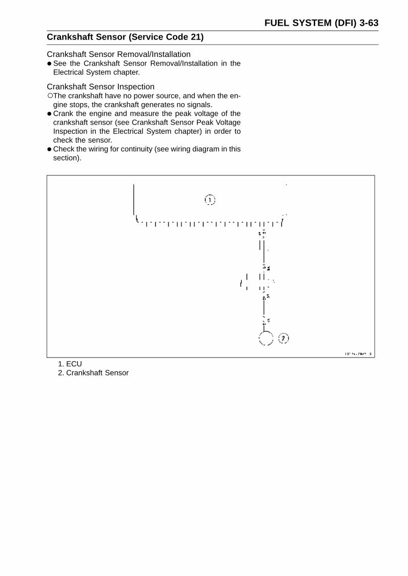
FUEL SYSTEM (DFI) 3-63Crankshaft Sensor (Service Code 21)
Crankshaft Sensor Removal/Installation•See the Crankshaft Sensor Removal/Installation in the
Electrical System chapter.
Crankshaft Sensor InspectionThe crankshaft have no power source, and when the en-
gine stops, the crankshaft generates no signals.
•Crank the engine and measure the peak voltage of thecrankshaft sensor (see Crankshaft Sensor Peak VoltageInspection in the Electrical System chapter) in order tocheck the sensor.
•Check the wiring for continuity (see wiring diagram in thissection).
1. ECU2. Crankshaft Sensor
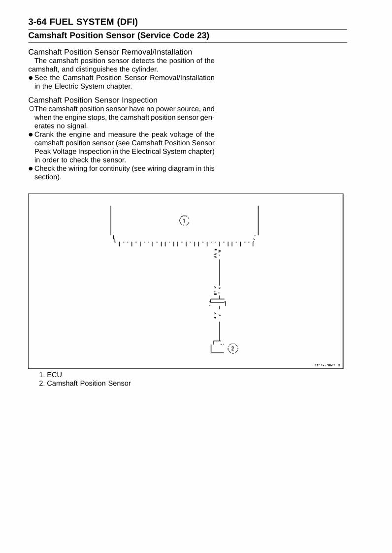
3-64 FUEL SYSTEM (DFI)Camshaft Position Sensor (Service Code 23)
Camshaft Position Sensor Removal/InstallationThe camshaft position sensor detects the position of the
camshaft, and distinguishes the cylinder.
• See the Camshaft Position Sensor Removal/Installationin the Electric System chapter.
Camshaft Position Sensor InspectionThe camshaft position sensor have no power source, and
when the engine stops, the camshaft position sensor gen-erates no signal.
• Crank the engine and measure the peak voltage of thecamshaft position sensor (see Camshaft Position SensorPeak Voltage Inspection in the Electrical System chapter)in order to check the sensor.
•Check the wiring for continuity (see wiring diagram in thissection).
1. ECU2. Camshaft Position Sensor
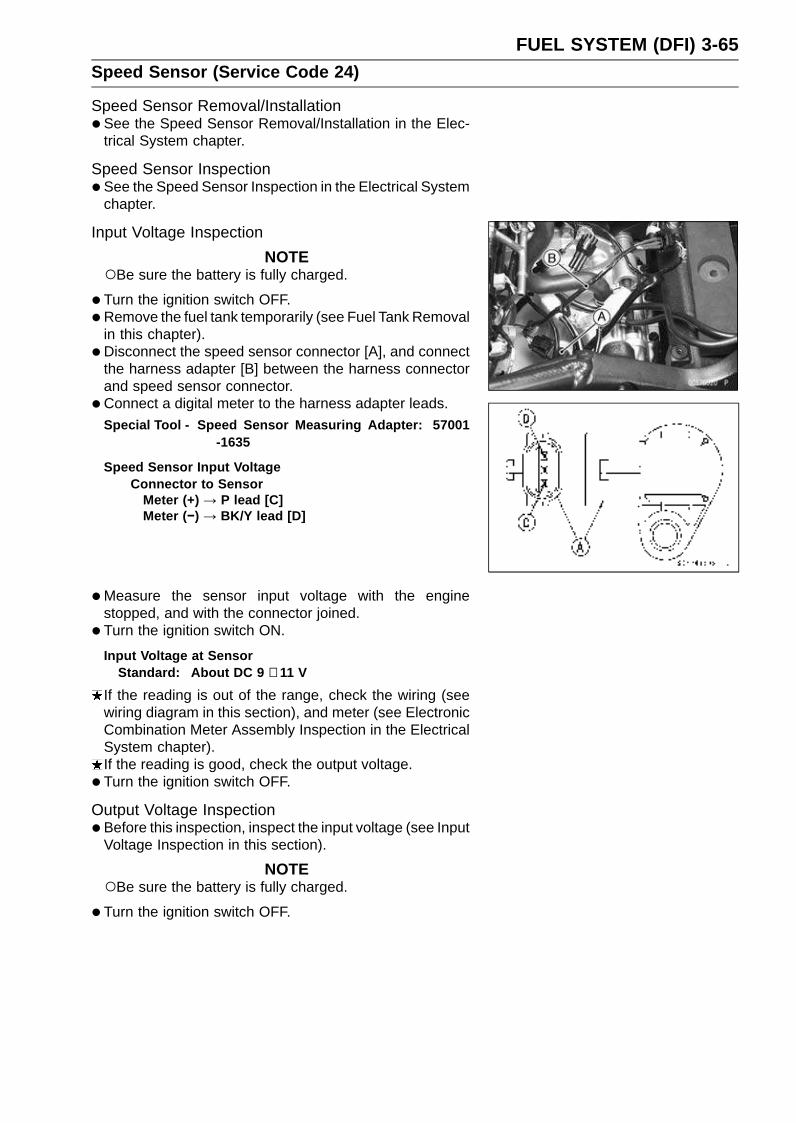
FUEL SYSTEM (DFI) 3-65Speed Sensor (Service Code 24)
Speed Sensor Removal/Installation•See the Speed Sensor Removal/Installation in the Elec-
trical System chapter.
Speed Sensor Inspection•See the Speed Sensor Inspection in the Electrical System
chapter.
Input Voltage Inspection
NOTEBe sure the battery is fully charged.
•Turn the ignition switch OFF.
•Remove the fuel tank temporarily (see Fuel Tank Removalin this chapter).
• Disconnect the speed sensor connector [A], and connectthe harness adapter [B] between the harness connectorand speed sensor connector.
• Connect a digital meter to the harness adapter leads.
Special Tool - Speed Sensor Measuring Adapter: 57001-1635
Speed Sensor Input VoltageConnector to Sensor
Meter (+) → P lead [C]Meter (−) → BK/Y lead [D]
•Measure the sensor input voltage with the enginestopped, and with the connector joined.
• Turn the ignition switch ON.
Input Voltage at SensorStandard: About DC 9 ∼ 11 V
If the reading is out of the range, check the wiring (seewiring diagram in this section), and meter (see ElectronicCombination Meter Assembly Inspection in the ElectricalSystem chapter).If the reading is good, check the output voltage.
• Turn the ignition switch OFF.
Output Voltage Inspection•Before this inspection, inspect the input voltage (see Input
Voltage Inspection in this section).
NOTEBe sure the battery is fully charged.
•Turn the ignition switch OFF.

3-66 FUEL SYSTEM (DFI)Speed Sensor (Service Code 24)
•Disconnect the speed sensor connector [A], and connectthe harness adapter [B] between the harness connectorand speed sensor connector.
• Connect a digital meter to the harness adapter leads.Special Tool - Speed Sensor Measuring Adapter: 57001
-1635
Speed Sensor Output VoltageConnections to Sensor
Meter (+) → Y lead [C]Meter (–) → BK/Y lead [D]
•Measure the sensor output voltage with the enginestopped, and with the connector joined.
• Turn the ignition switch ON.
Output Voltage at SensorStandard: About DC 0.05 ∼ 0.07 V
NOTEIf you can rotate the drive shaft, the output voltage will
be raise.
If the reading is out of the range, check the speed sensor(see Speed Sensor Inspection in the Electrical Systemchapter) and the wiring to ECU (see wiring diagram in thissection).If the reading, speed sensor and wiring are good, replacethe ECU (see ECU Removal/Installation in this chapter).
1. ECU2. Meter Unit3. Speed Sensor
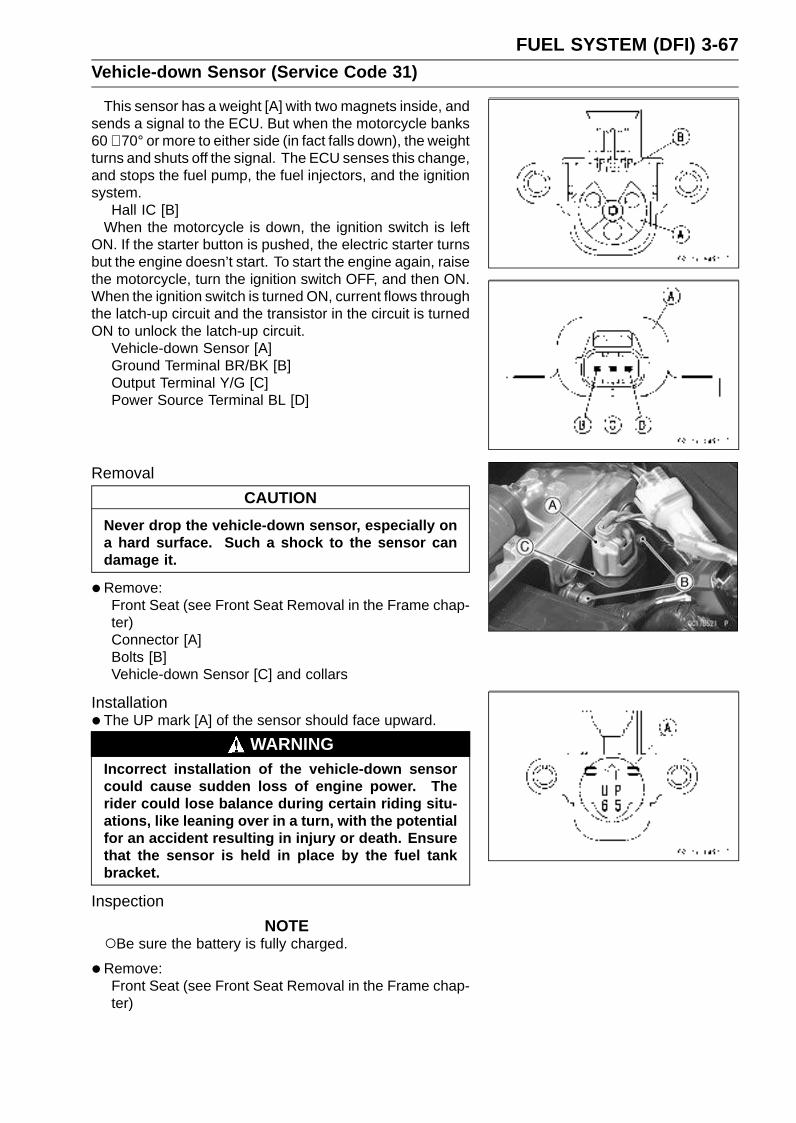
FUEL SYSTEM (DFI) 3-67Vehicle-down Sensor (Service Code 31)
This sensor has a weight [A] with two magnets inside, andsends a signal to the ECU. But when the motorcycle banks60 ∼ 70° or more to either side (in fact falls down), the weightturns and shuts off the signal. The ECU senses this change,and stops the fuel pump, the fuel injectors, and the ignitionsystem.
Hall IC [B]When the motorcycle is down, the ignition switch is left
ON. If the starter button is pushed, the electric starter turnsbut the engine doesn’t start. To start the engine again, raisethe motorcycle, turn the ignition switch OFF, and then ON.When the ignition switch is turned ON, current flows throughthe latch-up circuit and the transistor in the circuit is turnedON to unlock the latch-up circuit.
Vehicle-down Sensor [A]Ground Terminal BR/BK [B]Output Terminal Y/G [C]Power Source Terminal BL [D]
Removal
CAUTION
Never drop the vehicle-down sensor, especially ona hard surface. Such a shock to the sensor candamage it.
•Remove:Front Seat (see Front Seat Removal in the Frame chap-ter)Connector [A]Bolts [B]Vehicle-down Sensor [C] and collars
Installation•The UP mark [A] of the sensor should face upward.
WARNINGIncorrect installation of the vehicle-down sensorcould cause sudden loss of engine power. Therider could lose balance during certain riding situ-ations, like leaning over in a turn, with the potentialfor an accident resulting in injury or death. Ensurethat the sensor is held in place by the fuel tankbracket.
Inspection
NOTEBe sure the battery is fully charged.
•Remove:Front Seat (see Front Seat Removal in the Frame chap-ter)
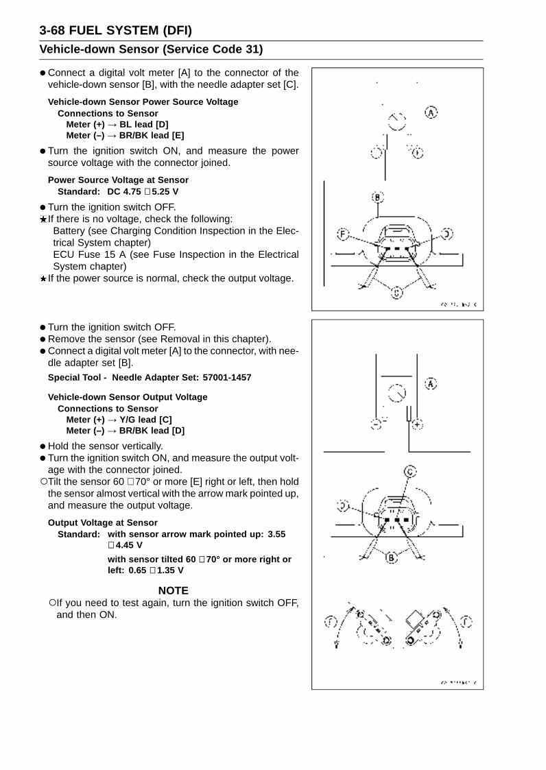
3-68 FUEL SYSTEM (DFI)Vehicle-down Sensor (Service Code 31)
•Connect a digital volt meter [A] to the connector of thevehicle-down sensor [B], with the needle adapter set [C].
Vehicle-down Sensor Power Source VoltageConnections to Sensor
Meter (+) → BL lead [D]Meter (–) → BR/BK lead [E]
•Turn the ignition switch ON, and measure the powersource voltage with the connector joined.
Power Source Voltage at SensorStandard: DC 4.75 ∼ 5.25 V
•Turn the ignition switch OFF.If there is no voltage, check the following:Battery (see Charging Condition Inspection in the Elec-trical System chapter)ECU Fuse 15 A (see Fuse Inspection in the ElectricalSystem chapter)
If the power source is normal, check the output voltage.
• Turn the ignition switch OFF.
•Remove the sensor (see Removal in this chapter).
• Connect a digital volt meter [A] to the connector, with nee-dle adapter set [B].Special Tool - Needle Adapter Set: 57001-1457
Vehicle-down Sensor Output VoltageConnections to Sensor
Meter (+) → Y/G lead [C]Meter (–) → BR/BK lead [D]
•Hold the sensor vertically.
• Turn the ignition switch ON, and measure the output volt-age with the connector joined.Tilt the sensor 60 ∼ 70° or more [E] right or left, then hold
the sensor almost vertical with the arrow mark pointed up,and measure the output voltage.
Output Voltage at SensorStandard: with sensor arrow mark pointed up: 3.55
∼ 4.45 V
with sensor tilted 60 ∼ 70° or more right orleft: 0.65 ∼ 1.35 V
NOTEIf you need to test again, turn the ignition switch OFF,
and then ON.

FUEL SYSTEM (DFI) 3-69Vehicle-down Sensor (Service Code 31)
•Turn the ignition switch OFF.
•Remove the needle adapter set, and apply siliconesealant to the seals of the connector for waterproofing.
Sealant - Kawasaki Bond (Silicone Sealant): 56019-120
If the output voltage is out of the specified, replace thevehicle-down sensor.
1. ECU2. Vehicle-down Sensor

3-70 FUEL SYSTEM (DFI)Subthrottle Sensor (Service Code 32)
Subthrottle Sensor Removal/Adjustment
CAUTION
Do not remove or adjust the subthrottle sensor [A]since it has been adjusted and set with precision atthe factory.Never drop the throttle body assy, especially on ahard surface. Such a shock to the sensor can dam-age it.
Subthrottle Sensor Connector [B]
Input Voltage Inspection
NOTEBe sure the battery is fully charged.
•Turn the ignition switch OFF.
•Remove the ECU (see ECU Removal in this chapter). Donot disconnect the ECU connectors.
•Connect a digital voltmeter [A] to the connector [B], usingthe needle adapter set.Special Tool - Needle Adapter Set: 57001-1457
Subthrottle Sensor Input VoltageConnections to ECU Connector
Meter (+) → BL lead (terminal 10)Meter (–) → BR/BK lead (terminal 28)
•Measure the input voltage with the engine stopped, andwith the connectors joined.
• Turn the ignition switch ON.
Input Voltage at ECU ConnectorStandard: DC 4.75 ∼ 5.25 V
•Turn the ignition switch OFF.If the reading of input voltage is less than the standard,check the ECU for its ground, power supply and wiringshorted.If the input voltage is within the standard range, check theinput voltage at the subthrottle sensor connector.
• Remove the throttle body assembly temporarily (seeThrottle Body Assy Removal in this chapter).
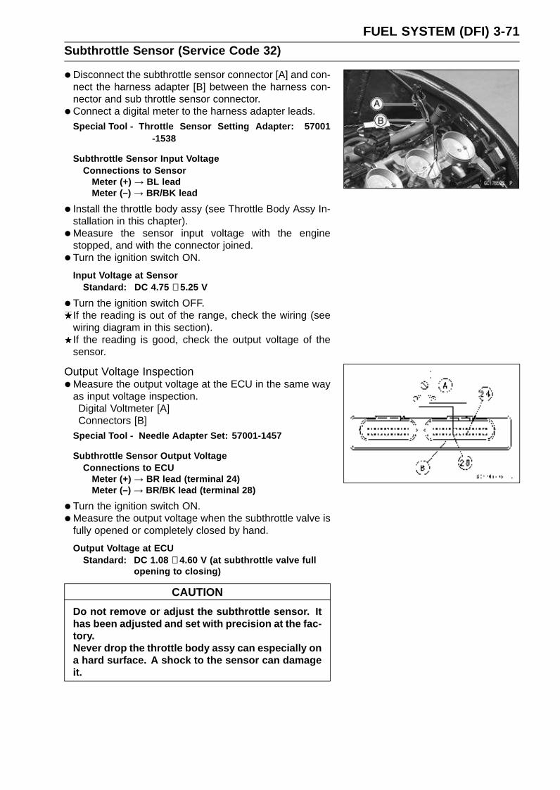
FUEL SYSTEM (DFI) 3-71Subthrottle Sensor (Service Code 32)
•Disconnect the subthrottle sensor connector [A] and con-nect the harness adapter [B] between the harness con-nector and sub throttle sensor connector.
• Connect a digital meter to the harness adapter leads.Special Tool - Throttle Sensor Setting Adapter: 57001
-1538
Subthrottle Sensor Input VoltageConnections to Sensor
Meter (+) → BL leadMeter (–) → BR/BK lead
• Install the throttle body assy (see Throttle Body Assy In-stallation in this chapter).
•Measure the sensor input voltage with the enginestopped, and with the connector joined.
• Turn the ignition switch ON.
Input Voltage at SensorStandard: DC 4.75 ∼ 5.25 V
•Turn the ignition switch OFF.If the reading is out of the range, check the wiring (seewiring diagram in this section).If the reading is good, check the output voltage of thesensor.
Output Voltage Inspection•Measure the output voltage at the ECU in the same way
as input voltage inspection.Digital Voltmeter [A]Connectors [B]
Special Tool - Needle Adapter Set: 57001-1457
Subthrottle Sensor Output VoltageConnections to ECU
Meter (+) → BR lead (terminal 24)Meter (–) → BR/BK lead (terminal 28)
•Turn the ignition switch ON.
•Measure the output voltage when the subthrottle valve isfully opened or completely closed by hand.
Output Voltage at ECUStandard: DC 1.08 ∼ 4.60 V (at subthrottle valve full
opening to closing)
CAUTION
Do not remove or adjust the subthrottle sensor. Ithas been adjusted and set with precision at the fac-tory.Never drop the throttle body assy can especially ona hard surface. A shock to the sensor can damageit.
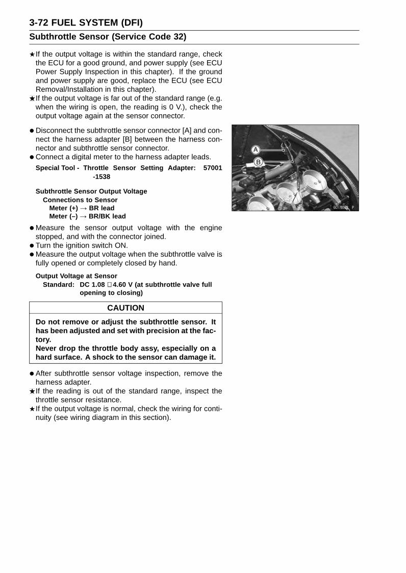
3-72 FUEL SYSTEM (DFI)Subthrottle Sensor (Service Code 32)
If the output voltage is within the standard range, checkthe ECU for a good ground, and power supply (see ECUPower Supply Inspection in this chapter). If the groundand power supply are good, replace the ECU (see ECURemoval/Installation in this chapter).If the output voltage is far out of the standard range (e.g.when the wiring is open, the reading is 0 V.), check theoutput voltage again at the sensor connector.
• Disconnect the subthrottle sensor connector [A] and con-nect the harness adapter [B] between the harness con-nector and subthrottle sensor connector.
• Connect a digital meter to the harness adapter leads.Special Tool - Throttle Sensor Setting Adapter: 57001
-1538
Subthrottle Sensor Output VoltageConnections to Sensor
Meter (+) → BR leadMeter (–) → BR/BK lead
•Measure the sensor output voltage with the enginestopped, and with the connector joined.
• Turn the ignition switch ON.
•Measure the output voltage when the subthrottle valve isfully opened or completely closed by hand.
Output Voltage at SensorStandard: DC 1.08 ∼ 4.60 V (at subthrottle valve full
opening to closing)
CAUTION
Do not remove or adjust the subthrottle sensor. Ithas been adjusted and set with precision at the fac-tory.Never drop the throttle body assy, especially on ahard surface. A shock to the sensor can damage it.
•After subthrottle sensor voltage inspection, remove theharness adapter.If the reading is out of the standard range, inspect thethrottle sensor resistance.If the output voltage is normal, check the wiring for conti-nuity (see wiring diagram in this section).
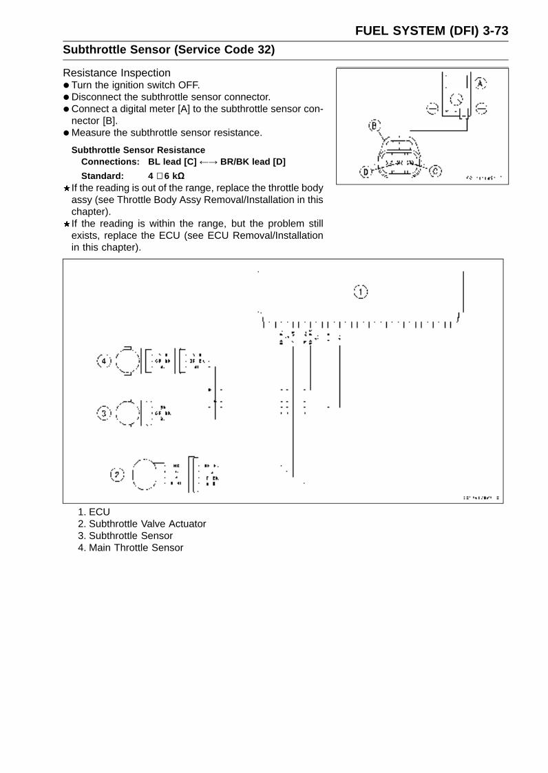
FUEL SYSTEM (DFI) 3-73Subthrottle Sensor (Service Code 32)
Resistance Inspection•Turn the ignition switch OFF.
•Disconnect the subthrottle sensor connector.
• Connect a digital meter [A] to the subthrottle sensor con-nector [B].
•Measure the subthrottle sensor resistance.
Subthrottle Sensor ResistanceConnections: BL lead [C] ←→ BR/BK lead [D]
Standard: 4 ∼ 6 kΩIf the reading is out of the range, replace the throttle bodyassy (see Throttle Body Assy Removal/Installation in thischapter).If the reading is within the range, but the problem stillexists, replace the ECU (see ECU Removal/Installationin this chapter).
1. ECU2. Subthrottle Valve Actuator3. Subthrottle Sensor4. Main Throttle Sensor
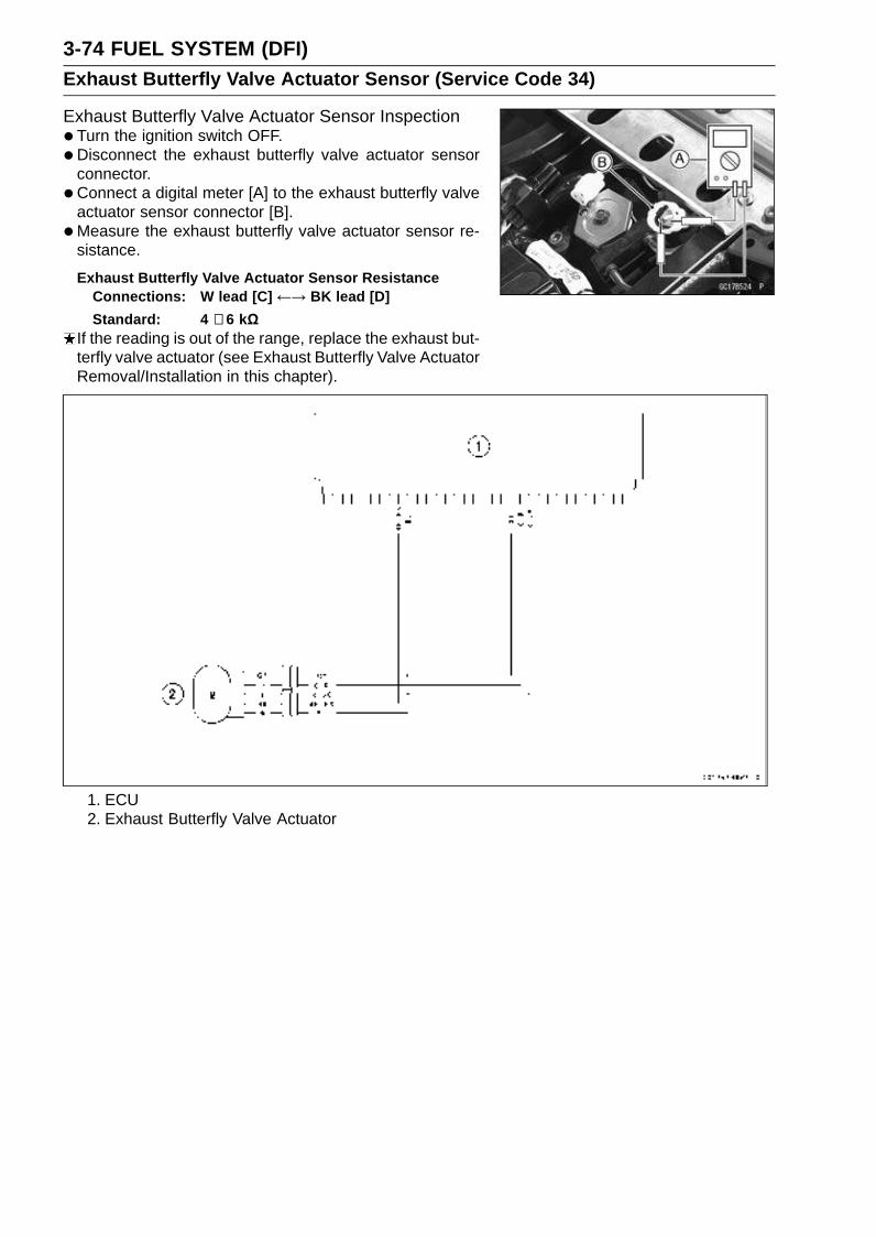
3-74 FUEL SYSTEM (DFI)Exhaust Butterfly Valve Actuator Sensor (Service Code 34)
Exhaust Butterfly Valve Actuator Sensor Inspection•Turn the ignition switch OFF.
•Disconnect the exhaust butterfly valve actuator sensorconnector.
• Connect a digital meter [A] to the exhaust butterfly valveactuator sensor connector [B].
•Measure the exhaust butterfly valve actuator sensor re-sistance.
Exhaust Butterfly Valve Actuator Sensor ResistanceConnections: W lead [C] ←→ BK lead [D]
Standard: 4 ∼ 6 kΩIf the reading is out of the range, replace the exhaust but-terfly valve actuator (see Exhaust Butterfly Valve ActuatorRemoval/Installation in this chapter).
1. ECU2. Exhaust Butterfly Valve Actuator
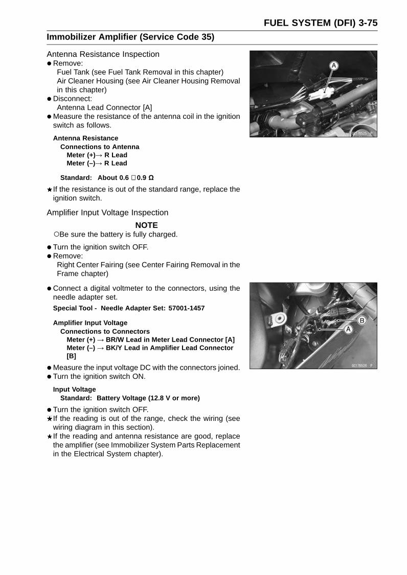
FUEL SYSTEM (DFI) 3-75Immobilizer Amplifier (Service Code 35)
Antenna Resistance Inspection•Remove:
Fuel Tank (see Fuel Tank Removal in this chapter)Air Cleaner Housing (see Air Cleaner Housing Removalin this chapter)
•Disconnect:Antenna Lead Connector [A]
•Measure the resistance of the antenna coil in the ignitionswitch as follows.
Antenna ResistanceConnections to Antenna
Meter (+)→ R LeadMeter (–)→ R Lead
Standard: About 0.6 ∼ 0.9 Ω
If the resistance is out of the standard range, replace theignition switch.
Amplifier Input Voltage Inspection
NOTEBe sure the battery is fully charged.
•Turn the ignition switch OFF.
•Remove:Right Center Fairing (see Center Fairing Removal in theFrame chapter)
•Connect a digital voltmeter to the connectors, using theneedle adapter set.Special Tool - Needle Adapter Set: 57001-1457
Amplifier Input VoltageConnections to Connectors
Meter (+) → BR/W Lead in Meter Lead Connector [A]Meter (–) → BK/Y Lead in Amplifier Lead Connector[B]
•Measure the input voltage DC with the connectors joined.
• Turn the ignition switch ON.
Input VoltageStandard: Battery Voltage (12.8 V or more)
•Turn the ignition switch OFF.If the reading is out of the range, check the wiring (seewiring diagram in this section).If the reading and antenna resistance are good, replacethe amplifier (see Immobilizer System Parts Replacementin the Electrical System chapter).

3-76 FUEL SYSTEM (DFI)Blank Key Detection (Service Code 36)
This code appears in the following conditions.The transponder [A] in the master and/or user key is mal-
function.When the spare key of unregistration is used.When the master key is registered in the registered ECU.Therefore, the service code 36 will disappear when theabove issue is solved.
User Key Inspection•Register the user key correctly (see Key Registration in
the Electrical System chapter).If the service code 36 appears again, the transponder inthe key is malfunction, replace it.
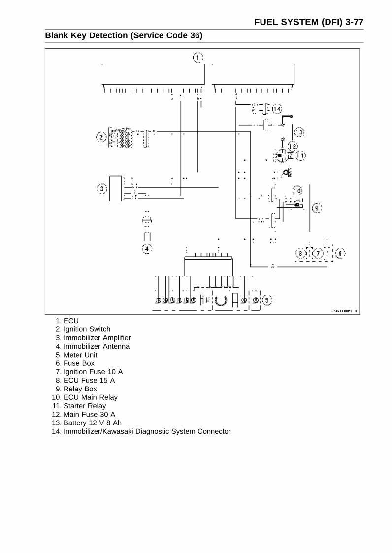
FUEL SYSTEM (DFI) 3-77Blank Key Detection (Service Code 36)
1. ECU2. Ignition Switch3. Immobilizer Amplifier4. Immobilizer Antenna5. Meter Unit6. Fuse Box7. Ignition Fuse 10 A8. ECU Fuse 15 A9. Relay Box
10. ECU Main Relay11. Starter Relay12. Main Fuse 30 A13. Battery 12 V 8 Ah14. Immobilizer/Kawasaki Diagnostic System Connector

3-78 FUEL SYSTEM (DFI)Stick Coils #1, #2, #3, #4: (Service Code 51, 52, 53, 54)
Stick Coil #1: Service Code 51Stick Coil #2: Service Code 52Stick Coil #3: Service Code 53Stick Coil #4: Service Code 54
Removal/Installation
CAUTION
Never drop the stick coils, especially on a hard sur-face. Such a shock to the stick coil can damage it.
•See the Stick Coil (Ignition Coil together with Spark PlugCap) Removal/Installation in the Electrical System chap-ter.
Input Voltage Inspection
NOTEBe sure the battery is fully charged.
•Turn the ignition switch OFF.
•Remove the ECU (see ECU Removal in this chapter). Donot disconnect the ECU connector.
• Connect a digital voltmeter [A] as shown, with the needleadapter set.Measure the input voltage to each primary winding of the
ignition coils with the engine stopped, and with the con-nectors joined.
• Turn the ignition switch ON.
Stick Coil Input Voltage at ECUConnections for Stick Coil #1
Meter (+) → BK lead (terminal 47)Meter (–) → BK/Y lead (terminal 59)
Connections for Stick Coil #2Meter (+) → BK/G lead (terminal 46)Meter (–) → BK/Y lead (terminal 59)
Connections for Stick Coil #3Meter (+) → BK/W lead (terminal 45)Meter (–) → BK/Y lead (terminal 59)
Connections for Stick Coil #4Meter (+) → BK/O lead (terminal 60)Meter (–) → BK/Y lead (terminal 59)
Input Voltage at ECUStandard: Battery Voltage (12.8 V or more)
If the reading is out of the standard, check the wiring (seewiring diagram in this section).If the reading is good, the input voltage is normal. Crankthe engine, and check the peak voltage of the stick coils(see Stick Coil Primary Peak Voltage Inspection in theElectrical System chapter) in order to check the primarycoils.
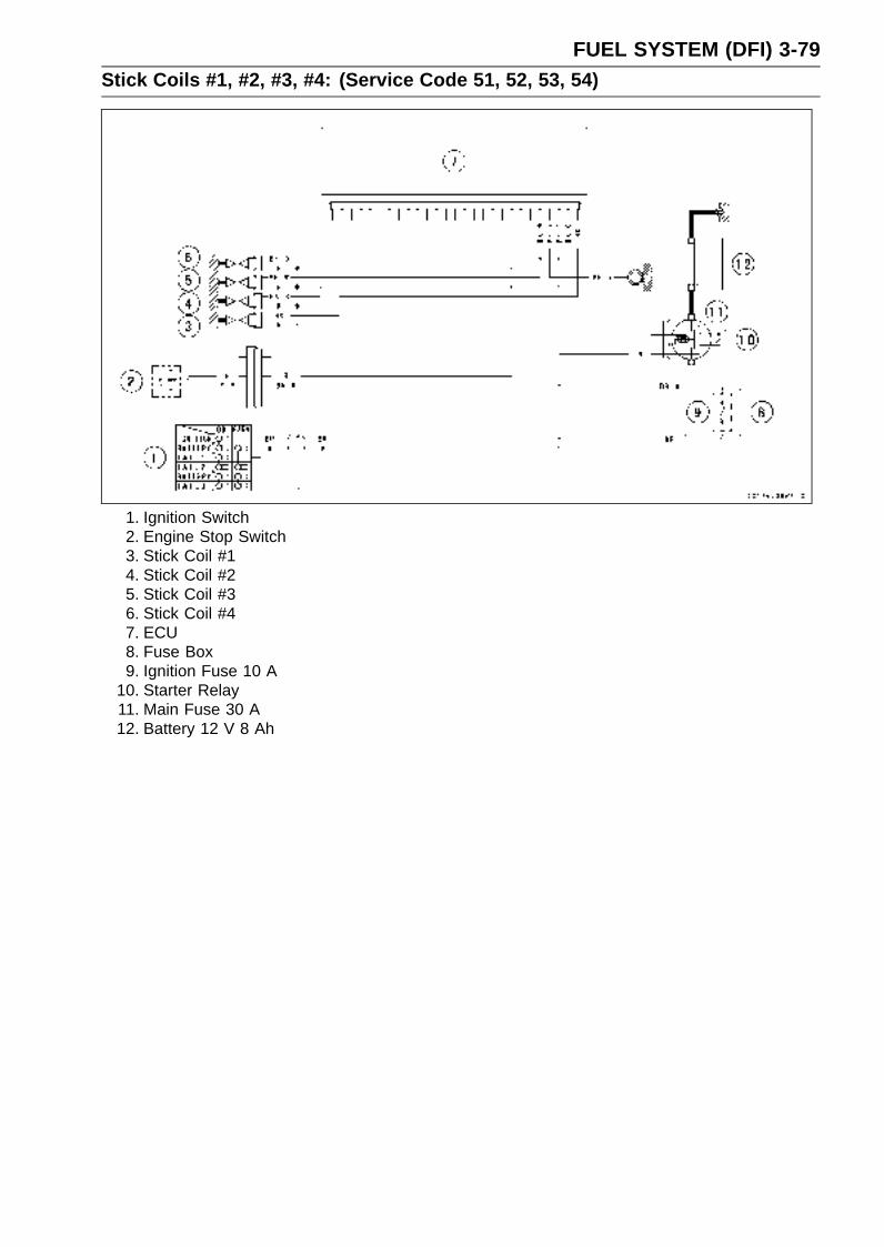
FUEL SYSTEM (DFI) 3-79Stick Coils #1, #2, #3, #4: (Service Code 51, 52, 53, 54)
1. Ignition Switch2. Engine Stop Switch3. Stick Coil #14. Stick Coil #25. Stick Coil #36. Stick Coil #47. ECU8. Fuse Box9. Ignition Fuse 10 A
10. Starter Relay11. Main Fuse 30 A12. Battery 12 V 8 Ah

3-80 FUEL SYSTEM (DFI)Subthrottle Valve Actuator (Service Code 62)
Subthrottle Valve Actuator Removal
CAUTION
Do not remove the subthrottle valve actuator [A]since it has been adjusted and set with precisionat the factory.Never drop the throttle body assy, especially on ahard surface. Such a shock to the actuator candamage it.
Subthrottle Valve Actuator Inspection•Remove the air cleaner housing (see Air Cleaner Housing
Removal in this chapter).
• Turn the ignition switch ON.
•Check to see that all subthrottle valves [A] open and closesmoothly.If the subthrottle valves do not operate, check the actua-tor internal resistance (see Resistance Inspection in thischapter).
Resistance Inspection•Turn the ignition switch OFF.
•Remove the subthrottle valve actuator connector.
• Connect a digital meter to the connector [A].
•Measure the subthrottle valve actuator resistance.
Subthrottle Valve Actuator ResistanceConnections: BK lead [1] ←→ P lead [2]
G lead [3] ←→ W/BL lead [4]
Standard: About 5 ∼ 7 Ω
If the reading is out of the range, replace the throttle bodyassy (see Throttle Body Assy Removal/Installation in thischapter).If the reading is within the range, check the input voltage(see Input Voltage Inspection in this section).

FUEL SYSTEM (DFI) 3-81Subthrottle Valve Actuator (Service Code 62)
Input Voltage Inspection
NOTEBe sure the battery is fully charged.
•Turn the ignition switch OFF.
•Connect the peak voltage adapter [A] and a digital meter[B] to the connector [C], using the needle adapter set [D].Special Tools - Peak Voltage Adapter: 57001-1415
Type: KEK-54-9-BNeedle Adapter Set: 57001-1457
Subthrottle Valve Actuator Input VoltageConnections to Harness Connector
(I) Meter (+) → BK/BL lead [1]
Meter (–) → P/BK lead [2]
(II) Meter (+) → G lead [3]
Meter (–) → W/BL lead [4]
•Measure the actuator input voltage with the enginestopped, and with the connector joined.
• Turn the ignition switch ON.
Input Voltage at SensorStandard: About DC 8.5 ∼ 10.5 V
If the reading is out of the range, check the wiring to ECU(see wiring diagram in this section).If the wiring is good, replace the ECU (see ECU Removalin this chapter).
1. ECU2. Subthrottle Valve Actuator3. Subthrottle Sensor4. Main Throttle Sensor

3-82 FUEL SYSTEM (DFI)Exhaust Butterfly Valve Actuator (Service Code 63)
Exhaust Butterfly Valve Actuator Removal•Remove:
Seat Cover (see Seat Cover Removal in the Framechapter)
• Put off the rubber boots of exhaust butterfly valve cables.
• Loosen the locknuts [A] and adjuster nut [B].
• Remove the guard bracket [C] (Refer to the ImmobilizerSystem Parts Replacement in the Electrical System chap-ter for Europe Model).
• Remove:Clamp [A]Exhaust Butterfly Valve Cables [B]Connectors [C]
•Remove the bolts [D] and exhaust butterfly valve actuator[E].
• Remove:Exhaust Butterfly Valve Actuator Pulley [A].
Hold the pulley with a suitable fool.
CAUTION
If the pulley bolt is removed without holding, theactuator damage will occur.
Exhaust Butterfly Valve Actuator Installation• Install the pulley [A] on the actuator.
• Hold the pulley with a suitable tool [B] and tighten the bolt.Torque - Exhaust Butterfly Valve Actuator Pulley Bolt: 4.9
N·m (0.50 kgf·m, 43 in·lb)
CAUTION
If the pulley bolt is tightened without holding, theactuator damage will occur.
•Confirm the pulley angle [A] (41.7° ±7°) as shown. It isoriginal position of the pulley.If the angle is not within the specified angle, adjust theactuator as follows.Connect the actuator connectors.Turn the ignition switch ON.Confirm the pulley turns clockwise and then counterclock-
wise, and clockwise againTurn the ignition switch OFF.Confirm the pulley turns counterclockwise little.The position is original position of the pulley.
If the position is not within the specified angle above, re-place the exhaust butterfly valve actuator.
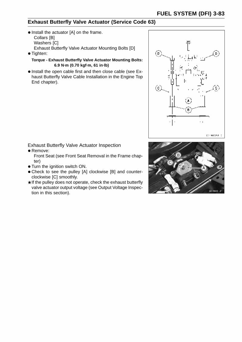
FUEL SYSTEM (DFI) 3-83Exhaust Butterfly Valve Actuator (Service Code 63)
• Install the actuator [A] on the frame.Collars [B]Washers [C]Exhaust Butterfly Valve Actuator Mounting Bolts [D]
• Tighten:Torque - Exhaust Butterfly Valve Actuator Mounting Bolts:
6.9 N·m (0.70 kgf·m, 61 in·lb)
• Install the open cable first and then close cable (see Ex-haust Butterfly Valve Cable Installation in the Engine TopEnd chapter).
Exhaust Butterfly Valve Actuator Inspection•Remove:
Front Seat (see Front Seat Removal in the Frame chap-ter)
• Turn the ignition switch ON.
•Check to see the pulley [A] clockwise [B] and counter-clockwise [C] smoothly.If the pulley does not operate, check the exhaust butterflyvalve actuator output voltage (see Output Voltage Inspec-tion in this section).

3-84 FUEL SYSTEM (DFI)Exhaust Butterfly Valve Actuator (Service Code 63)
Output Voltage Inspection•Remove:
Front Seat (see Front Seat Removal in the Frame chap-ter)
•Measure the output voltage at the 3 pins connector ofthe exhaust butterfly valve actuator [A] when the pulleyis original position as follows.
•Disconnect:2 pins Connector [B]3 pins Connector [C]
•Connect the adapter [D] between the 3 pins connectorsand digital voltmeter [E].Main Harness [F]
Special Tool - Throttle Sensor Setting Adapter #1: 57001-1400
ConnectionsMeter (+) → BL Lead [G] in Adapter (Y Lead of
Actuator)
Meter (–) → BK/BL Lead [H] in Adapter (BK Lead ofActuator)
•Turn the ignition switch ON and wait until the pulley stops.
• Turn the ignition switch OFF and wait until the pulleystops.
Actuator Output Voltage (Pulley Original Position)Standard: 3.46 ∼ 3.76 V
If the output voltage is out of the standard, remove theactuator and check the original position of pulley (see Ex-haust Butterfly Valve Actuator Installation in this chapter).
1. ECU2. Exhaust Butterfly Valve Actuator
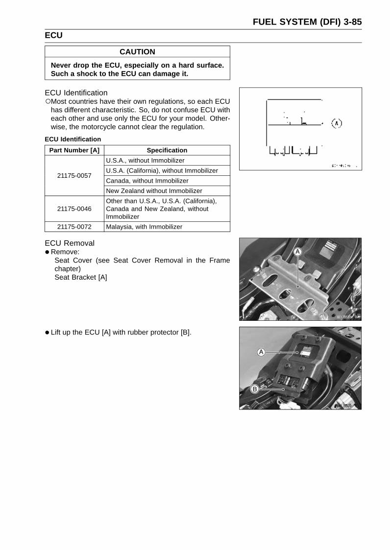
FUEL SYSTEM (DFI) 3-85ECU
CAUTION
Never drop the ECU, especially on a hard surface.Such a shock to the ECU can damage it.
ECU IdentificationMost countries have their own regulations, so each ECU
has different characteristic. So, do not confuse ECU witheach other and use only the ECU for your model. Other-wise, the motorcycle cannot clear the regulation.
ECU Identification
Part Number [A] Specification
U.S.A., without Immobilizer
U.S.A. (California), without Immobilizer
Canada, without Immobilizer21175-0057
New Zealand without Immobilizer
21175-0046Other than U.S.A., U.S.A. (California),Canada and New Zealand, withoutImmobilizer
21175-0072 Malaysia, with Immobilizer
ECU Removal•Remove:
Seat Cover (see Seat Cover Removal in the Framechapter)Seat Bracket [A]
• Lift up the ECU [A] with rubber protector [B].

3-86 FUEL SYSTEM (DFI)ECU
•Remove:ECU Lead Connectors [A]ECU [B]
•Refer to the Immobilizer System Parts Replacement in theElectrical System chapter for Europe model.
ECU Installation• Install:
ECU [A] (In rubber protector [B])ECU Lead Connectors
ECU Power Supply Inspection•Visually inspect the terminals [A] of the ECU connectors.
If the connector is clogged with mud or dust, blow it offwith compressed air.Replace the main harness if the terminals of the mainharness connectors are cracked, bent, or otherwise dam-aged.Replace the ECU if the terminals of the ECU connectorsare cracked, bent, or otherwise damaged (see ECU Re-moval/Installation in this chapter).
•With the ECU connectors connected, check the followingground lead for continuity with the ignition switch OFF,using a tester and needle adapter set.Special Tool - Needle Adapter Set: 57001-1457
ECU Grounding Inspection
34, 58, or 59 Terminal(BK/Y)
←→ Battery (–) Terminal: 0 Ω
Engine Ground ←→ Battery (–) Terminal: 0 Ω
If no continuity, check the connector, the engine groundlead, or main harness, and repair or replace them if nec-essary.
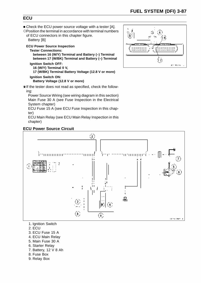
FUEL SYSTEM (DFI) 3-87ECU
•Check the ECU power source voltage with a tester [A].Position the terminal in accordance with terminal numbers
of ECU connectors in this chapter figure.Battery [B]
ECU Power Source InspectionTester Connections:
between 16 (W/Y) Terminal and Battery (–) Terminalbetween 17 (W/BK) Terminal and Battery (–) Terminal
Ignition Switch OFF:16 (W/Y) Terminal 0 V,17 (W/BK) Terminal Battery Voltage (12.8 V or more)
Ignition Switch ON:Battery Voltage (12.8 V or more)
If the tester does not read as specified, check the follow-ing:Power Source Wiring (see wiring diagram in this section)Main Fuse 30 A (see Fuse Inspection in the ElectricalSystem chapter)ECU Fuse 15 A (see ECU Fuse Inspection in this chap-ter)ECU Main Relay (see ECU Main Relay Inspection in thischapter)
ECU Power Source Circuit
1. Ignition Switch2. ECU3. ECU Fuse 15 A4. ECU Main Relay5. Main Fuse 30 A6. Starter Relay7. Battery, 12 V 8 Ah8. Fuse Box9. Relay Box

3-88 FUEL SYSTEM (DFI)DFI Power Source
ECU Fuse Removal•Refer to the Electrical System chapter for the ECU Fuse
Removal.
ECU Fuse InstallationIf a fuse fails during operation, inspect the DFI system todetermine the cause, and then replace it with a new fuseof proper amperage.
•Refer to the Electrical System chapter for the ECU FuseInstallation.
ECU Fuse Inspection•Refer to the Electrical System chapter for the ECU Fuse
Inspection.
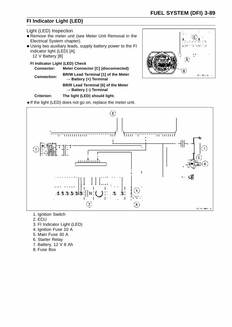
FUEL SYSTEM (DFI) 3-89FI Indicator Light (LED)
Light (LED) Inspection•Remove the meter unit (see Meter Unit Removal in the
Electrical System chapter).
• Using two auxiliary leads, supply battery power to the FIindicator light (LED) [A].12 V Battery [B]
FI Indicator Light (LED) CheckConnector: Meter Connector [C] (disconnected)
Connection:BR/W Lead Terminal [1] of the Meter→ Battery (+) Terminal
BR/R Lead Terminal [6] of the Meter→ Battery (–) Terminal
Criterion: The light (LED) should light.
If the light (LED) does not go on, replace the meter unit.
1. Ignition Switch2. ECU3. FI Indicator Light (LED)4. Ignition Fuse 10 A5. Main Fuse 30 A6. Starter Relay7. Battery, 12 V 8 Ah8. Fuse Box
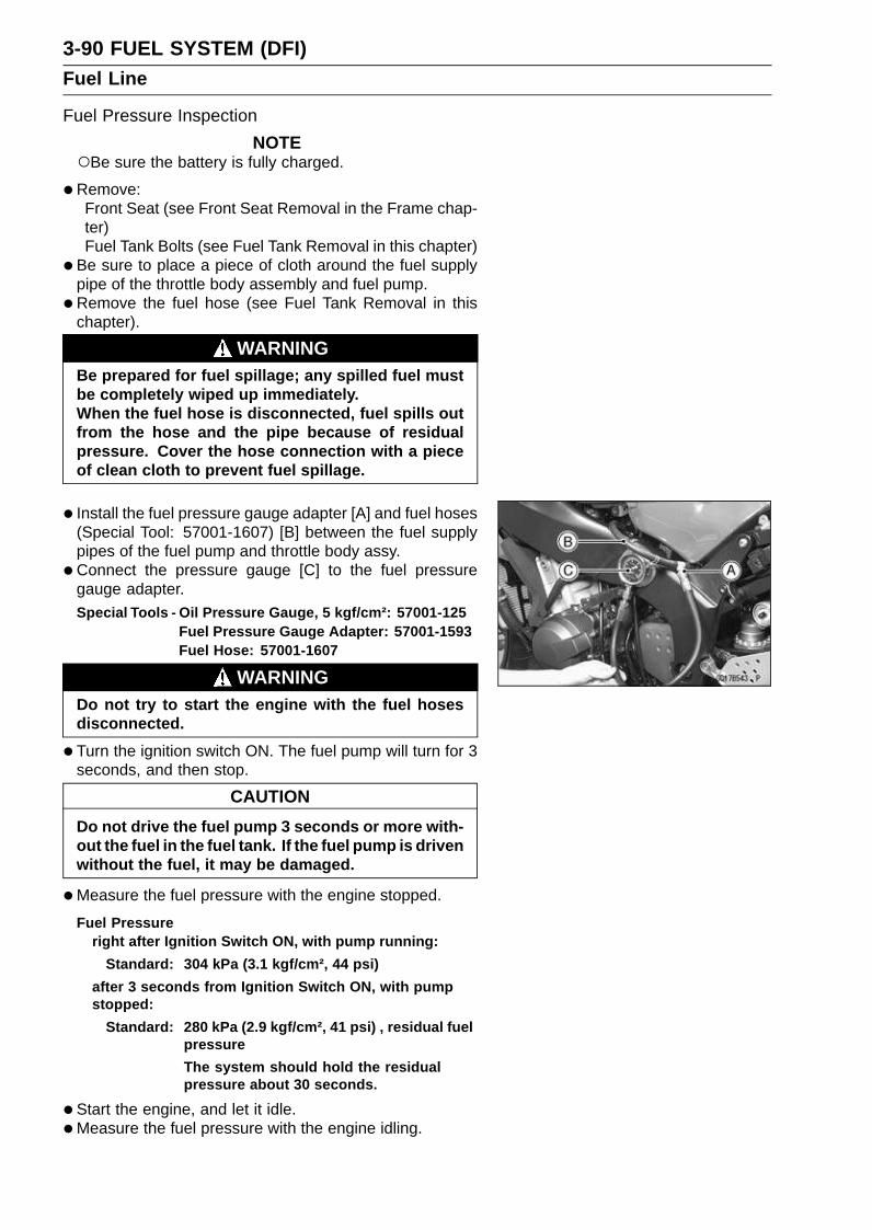
3-90 FUEL SYSTEM (DFI)Fuel Line
Fuel Pressure Inspection
NOTEBe sure the battery is fully charged.
•Remove:Front Seat (see Front Seat Removal in the Frame chap-ter)Fuel Tank Bolts (see Fuel Tank Removal in this chapter)
• Be sure to place a piece of cloth around the fuel supplypipe of the throttle body assembly and fuel pump.
•Remove the fuel hose (see Fuel Tank Removal in thischapter).
WARNINGBe prepared for fuel spillage; any spilled fuel mustbe completely wiped up immediately.When the fuel hose is disconnected, fuel spills outfrom the hose and the pipe because of residualpressure. Cover the hose connection with a pieceof clean cloth to prevent fuel spillage.
• Install the fuel pressure gauge adapter [A] and fuel hoses(Special Tool: 57001-1607) [B] between the fuel supplypipes of the fuel pump and throttle body assy.
•Connect the pressure gauge [C] to the fuel pressuregauge adapter.Special Tools - Oil Pressure Gauge, 5 kgf/cm²: 57001-125
Fuel Pressure Gauge Adapter: 57001-1593Fuel Hose: 57001-1607
WARNINGDo not try to start the engine with the fuel hosesdisconnected.
•Turn the ignition switch ON. The fuel pump will turn for 3seconds, and then stop.
CAUTION
Do not drive the fuel pump 3 seconds or more with-out the fuel in the fuel tank. If the fuel pump is drivenwithout the fuel, it may be damaged.
•Measure the fuel pressure with the engine stopped.
Fuel Pressureright after Ignition Switch ON, with pump running:
Standard: 304 kPa (3.1 kgf/cm², 44 psi)
after 3 seconds from Ignition Switch ON, with pumpstopped:
Standard: 280 kPa (2.9 kgf/cm², 41 psi) , residual fuelpressure
The system should hold the residualpressure about 30 seconds.
•Start the engine, and let it idle.
•Measure the fuel pressure with the engine idling.
FUEL SYSTEM (DFI) 3-91Fuel Line
Fuel Pressure (Idling)Standard: 304 kPa (3.1 kgf/cm², 44 psi)
NOTEThe gauge hand will fluctuate. Read the pressure at the
average of the maximum and minimum indications.
If the fuel pressure is much higher than the specified, re-place the fuel pump (see Fuel Pump Removal/Installationin this chapter).If the fuel pressure is much lower than specified, checkthe following:Fuel Line LeakageAmount of Fuel Flow (see Fuel Flow Rate Inspection inthis chapter)
If the fuel pressure is much lower than specified, and ifinspection above checks out good, replace the throttlebody assy, nozzle assy or the fuel pump and measurethe fuel pressure again (see appropriate sections).
• Remove the fuel pressure gauge, fuel hoses and adapter.
• Install the fuel tank (see Fuel Tank Installation in this chap-ter).
Fuel Flow Rate Inspection
NOTEBe sure the battery is fully charged.
WARNINGGasoline is extremely flammable and can be explo-sive under certain conditions. Make sure the areais well-ventilated and free from any source of flameor sparks; this includes any appliance with a pilotlight. Do not smoke. Turn the ignition switch OFF.Be prepared for fuel spillage; any spilled fuel mustbe completely wiped up immediately.
•Turn the ignition switch, and engine stop switch OFF.
•Wait until the engine cools down.
• Prepare a fuel hose of the inside diameter 7.5 mm (0.30in.) and a measuring cylinder.
• Remove:Front Seat (see Front Seat Removal in the Frame chap-ter)Fuel Tank Bolts (see Fuel Tank Removal in this chapter)

3-92 FUEL SYSTEM (DFI)Fuel Line
•Open the fuel tank cap [A] to lower the pressure in thetank.
• Be sure to place a piece of cloth around the fuel supplypipe of the fuel pump.
•Remove the fuel hose from the fuel supply pipe of the fuelpump (see Fuel Tank Removal in this chapter).
WARNINGBe prepared for fuel spillage; any spilled fuel mustbe completely wiped up immediately.When the fuel hose is disconnected, fuel spills outfrom the hose and the pipe because of residualpressure. Cover the hose connection with a pieceof clean cloth to prevent fuel spillage.
•Connect the prepared fuel hose [A] to the fuel supply pipeof the fuel pump.
• Secure the fuel hose with a clamp.
• Insert the fuel hose into the measuring cylinder [B].
WARNINGWipe off spilled out fuel immediately.Be sure to hold the measuring cylinder vertical.
•Close the fuel tank cap.
•With the engine stopped, turn the ignition switch ON. Thefuel pump should operate for 3 seconds, and then shouldstop.
CAUTION
Do not drive the fuel pump 3 seconds or more with-out the fuel in the fuel tank. If the fuel pump is drivenwithout the fuel, it may be damaged.
•Measure the discharge for 3 seconds.Repeat this operation several times.
Amount of Fuel FlowStandard: 67 mL (2.27 US oz) or more for 3 seconds
If the fuel flow is much less than the specified, check thefollowing:Battery Condition (see Charging Condition Inspection inthe Electrical System chapter)
• After inspection, connect the fuel hoses (see Fuel TankInstallation in this chapter).
• Start the engine and check for fuel leakage.
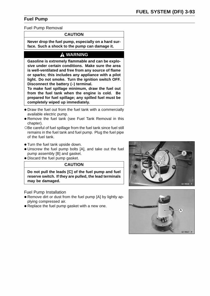
FUEL SYSTEM (DFI) 3-93Fuel Pump
Fuel Pump Removal
CAUTION
Never drop the fuel pump, especially on a hard sur-face. Such a shock to the pump can damage it.
WARNINGGasoline is extremely flammable and can be explo-sive under certain conditions. Make sure the areais well-ventilated and free from any source of flameor sparks; this includes any appliance with a pilotlight. Do not smoke. Turn the ignition switch OFF.Disconnect the battery (–) terminal.To make fuel spillage minimum, draw the fuel outfrom the fuel tank when the engine is cold. Beprepared for fuel spillage; any spilled fuel must becompletely wiped up immediately.
•Draw the fuel out from the fuel tank with a commerciallyavailable electric pump.
•Remove the fuel tank (see Fuel Tank Removal in thischapter).Be careful of fuel spillage from the fuel tank since fuel still
remains in the fuel tank and fuel pump. Plug the fuel pipeof the fuel tank.
• Turn the fuel tank upside down.
•Unscrew the fuel pump bolts [A], and take out the fuelpump assembly [B] and gasket.
• Discard the fuel pump gasket.
CAUTION
Do not pull the leads [C] of the fuel pump and fuelreserve switch. If they are pulled, the lead terminalsmay be damaged.
Fuel Pump Installation•Remove dirt or dust from the fuel pump [A] by lightly ap-
plying compressed air.
• Replace the fuel pump gasket with a new one.

3-94 FUEL SYSTEM (DFI)Fuel Pump
•Check that the fuel pump terminals [A], fuel reserve switchterminal [B] and band [C] are in place.Front [D]
• Apply a non-permanent locking agent to the threads ofthe fuel pump bolts.
• Tighten the fuel pump bolts to a snug fit following the tight-ening sequence shown.
• Following the tightening sequence, tighten the fuel pumpbolts to the specified torque.Torque - Fuel Pump Bolts: 9.8 N·m (1.0 kgf·m, 87 in·lb)
•Tighten the fuel pump bolts again to check the tightnessin the order shown.
Operation Inspection
NOTEBe sure the battery is fully charged.
•Turn the ignition switch ON and make sure that the fuelpump operates (make light sounds) for 3 seconds, andthen stops.
• Turn the ignition switch OFF.If the pump does not work as described above, inspectthe operating voltage.
Operating Voltage Inspection
NOTEBe sure the battery is fully charged.
•Turn the ignition switch OFF.
•Connect the hand tester (25 V DC) to the connector [A],with needle adapter set.Special Tools - Hand Tester: 57001-1394
Needle Adapter Set: 57001-1457
Measure the operating voltage with the engine stopped,and with the connector joined.
• Turn the ignition switch ON.The tester needle should indicate battery voltage for 3
seconds, and then 0 V.
Pump Operating Voltage at PumpConnections to Pump Connectors
Tester (+) → Y/R LeadTester (–) → BK/W Lead
Operating Voltage at Pump ConnectorStandard: Battery Voltage (12.8 V) for 3 seconds, and
then 0 V
If the reading stays on battery voltage, and never shows0 V. Check the ECU and fuel pump relay.If the voltage is in specification, but the pump doesn’twork, replace the pump (see Fuel Pump Removal/Instal-lation in this chapter).If there is still no battery voltage, check the pump relay(see Fuel Pump Relay Inspection in this chapter).
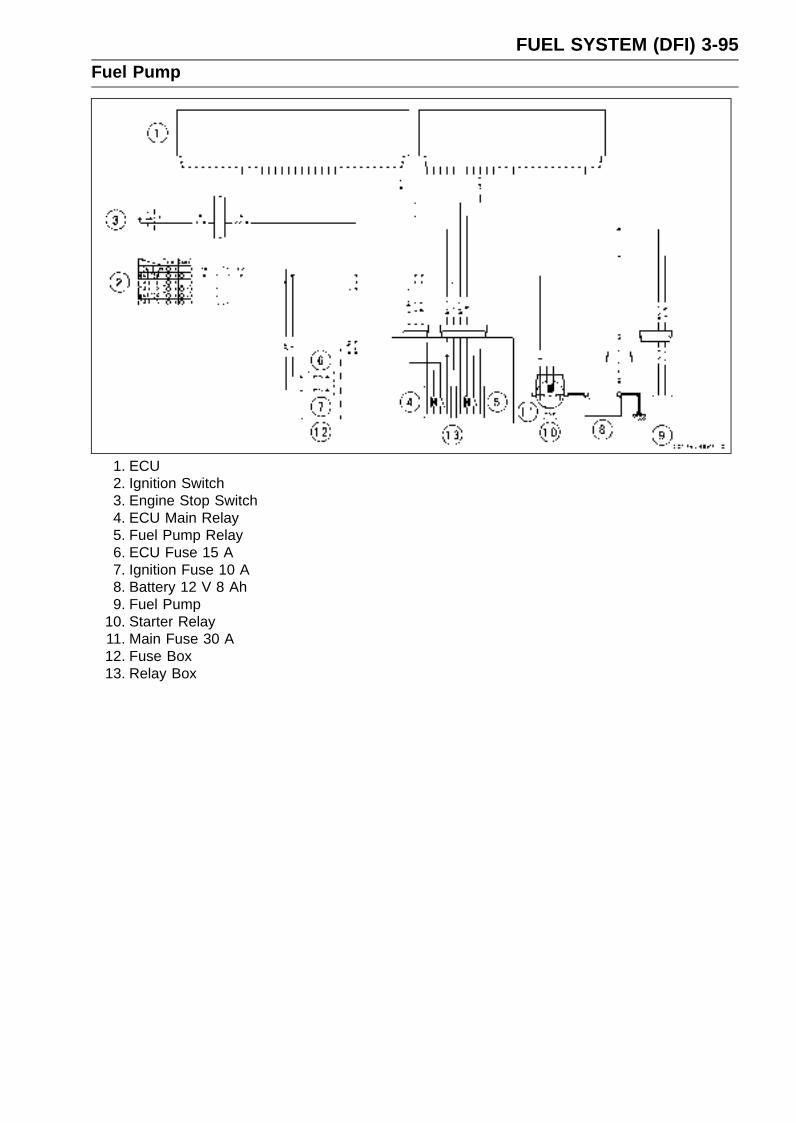
FUEL SYSTEM (DFI) 3-95Fuel Pump
1. ECU2. Ignition Switch3. Engine Stop Switch4. ECU Main Relay5. Fuel Pump Relay6. ECU Fuse 15 A7. Ignition Fuse 10 A8. Battery 12 V 8 Ah9. Fuel Pump
10. Starter Relay11. Main Fuse 30 A12. Fuse Box13. Relay Box
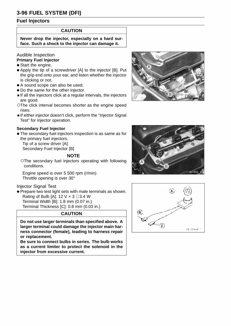
3-96 FUEL SYSTEM (DFI)Fuel Injectors
CAUTION
Never drop the injector, especially on a hard sur-face. Such a shock to the injector can damage it.
Audible InspectionPrimary Fuel Injector
•Start the engine.
• Apply the tip of a screwdriver [A] to the injector [B]. Putthe grip end onto your ear, and listen whether the injectoris clicking or not.
• A sound scope can also be used.
•Do the same for the other injector.If all the injectors click at a regular intervals, the injectorsare good.The click interval becomes shorter as the engine speed
rises.If either injector doesn’t click, perform the “Injector SignalTest” for injector operation.
Secondary Fuel Injector
•The secondary fuel injectors inspection is as same as forthe primary fuel injectors.Tip of a screw driver [A]Secondary Fuel Injector [B]
NOTEThe secondary fuel injectors operating with following
conditions.
Engine speed is over 5 500 rpm (r/min)Throttle opening is over 30°
Injector Signal Test•Prepare two test light sets with male terminals as shown.
Rating of Bulb [A]: 12 V × 3 ∼ 3.4 WTerminal Width [B]: 1.8 mm (0.07 in.)Terminal Thickness [C]: 0.8 mm (0.03 in.)
CAUTION
Do not use larger terminals than specified above. Alarger terminal could damage the injector main har-ness connector (female), leading to harness repairor replacement.Be sure to connect bulbs in series. The bulb worksas a current limiter to protect the solenoid in theinjector from excessive current.
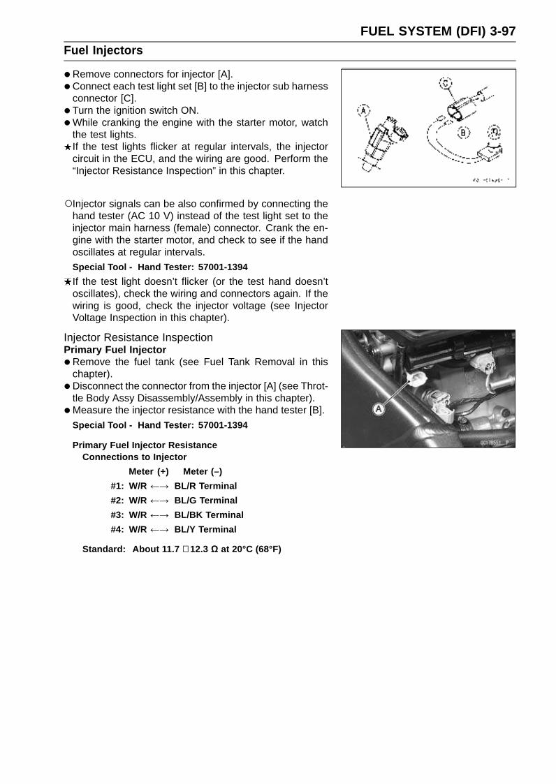
FUEL SYSTEM (DFI) 3-97Fuel Injectors
•Remove connectors for injector [A].
• Connect each test light set [B] to the injector sub harnessconnector [C].
• Turn the ignition switch ON.
•While cranking the engine with the starter motor, watchthe test lights.If the test lights flicker at regular intervals, the injectorcircuit in the ECU, and the wiring are good. Perform the“Injector Resistance Inspection” in this chapter.
Injector signals can be also confirmed by connecting thehand tester (AC 10 V) instead of the test light set to theinjector main harness (female) connector. Crank the en-gine with the starter motor, and check to see if the handoscillates at regular intervals.Special Tool - Hand Tester: 57001-1394
If the test light doesn’t flicker (or the test hand doesn’toscillates), check the wiring and connectors again. If thewiring is good, check the injector voltage (see InjectorVoltage Inspection in this chapter).
Injector Resistance InspectionPrimary Fuel Injector
•Remove the fuel tank (see Fuel Tank Removal in thischapter).
• Disconnect the connector from the injector [A] (see Throt-tle Body Assy Disassembly/Assembly in this chapter).
•Measure the injector resistance with the hand tester [B].
Special Tool - Hand Tester: 57001-1394
Primary Fuel Injector ResistanceConnections to Injector
Meter (+) Meter (–)
#1: W/R ←→ BL/R Terminal
#2: W/R ←→ BL/G Terminal
#3: W/R ←→ BL/BK Terminal
#4: W/R ←→ BL/Y Terminal
Standard: About 11.7 ∼ 12.3 Ω at 20°C (68°F)

3-98 FUEL SYSTEM (DFI)Fuel Injectors
Secondary Fuel Injector
•Remove the fuel tank (see Fuel Tank Removal in thischapter).
• Disconnect the connector from the injector [A] (see Noz-zle Assy Removal in this chapter).
•Measure the injector resistance with the hand tester.Special Tool - Hand Tester: 57001-1394
Secondary Fuel Injector ResistanceConnections to Injectors
Meter (+) Meter (–)
#1: W/R ←→ O/R Terminal
#2: W/R ←→ O/G Terminal
#3: W/R ←→ O/BK Terminal
#4: W/R ←→ O/Y Terminal
Standard: About 11.1 ∼ 12.3 Ω at 20°C (68°F)
If the reading is out of the range, perform the “Injector UnitTest” in this chapter.If the reading is normal, perform the “Injector Unit Test”for confirmation in this chapter.
Injector Unit Test•Use two leads [A] and the same test light set [B] as in
“Injector Signal Test” in this chapter.Rating of Bulb [C]: 12 V × (3 ∼ 3.4) W12 V Battery [D]
CAUTION
Be sure to connect the bulb in series. The bulbworks as a current limiter to protect the solenoidin the injector from excessive current.
•Connect the test light set to the injector [E] as shown.
•Open and connect [F] the end of the lead to the battery(–) terminal repeatedly. The injector should click.If the injector does not click, replace the injector.
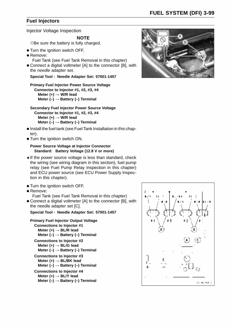
FUEL SYSTEM (DFI) 3-99Fuel Injectors
Injector Voltage Inspection
NOTEBe sure the battery is fully charged.
•Turn the ignition switch OFF.
•Remove:Fuel Tank (see Fuel Tank Removal in this chapter)
•Connect a digital voltmeter [A] to the connector [B], withthe needle adapter set.
Special Tool - Needle Adapter Set: 57001-1457
Primary Fuel Injector Power Source VoltageConnector to Injector #1, #2, #3, #4
Meter (+) → W/R leadMeter (–) → Battery (–) Terminal
Secondary Fuel Injector Power Source VoltageConnector to Injector #1, #2, #3, #4
Meter (+) → W/R leadMeter (–) → Battery (–) Terminal
• Install the fuel tank (see Fuel Tank Installation in this chap-ter).
• Turn the ignition switch ON.
Power Source Voltage at Injector ConnectorStandard: Battery Voltage (12.8 V or more)
If the power source voltage is less than standard, checkthe wiring (see wiring diagram in this section), fuel pumprelay (see Fuel Pump Relay Inspection in this chapter)and ECU power source (see ECU Power Supply Inspec-tion in this chapter).
• Turn the ignition switch OFF.
•Remove:Fuel Tank (see Fuel Tank Removal in this chapter)
•Connect a digital voltmeter [A] to the connector [B], withthe needle adapter set [C].
Special Tool - Needle Adapter Set: 57001-1457
Primary Fuel Injector Output VoltageConnections to Injector #1
Meter (+) → BL/R leadMeter (–) → Battery (–) Terminal
Connections to Injector #2Meter (+) → BL/G leadMeter (–) → Battery (–) Terminal
Connections to Injector #3Meter (+) → BL/BK leadMeter (–) → Battery (–) Terminal
Connections to Injector #4Meter (+) → BL/Y leadMeter (–) → Battery (–) Terminal

3-100 FUEL SYSTEM (DFI)Fuel Injectors
Secondary Fuel Injector Output VoltageConnections to Injector #1
Meter (+) → O/R leadMeter (–) → Battery (–) Terminal
Connections to Injector #2Meter (+) → O/G leadMeter (–) → Battery (–) Terminal
Connections to Injector #3Meter (+) → O/BK leadMeter (–) → Battery (–) Terminal
Connections to Injector #4Meter (+) → O/Y leadMeter (–) → Battery (–) Terminal
• Install the fuel tank (see Fuel Tank Installation in this chap-ter).
• Turn the ignition switch ON.
Output Voltage at Injector ConnectorStandard: Battery Voltage (12.8 V or more)
NOTEThe secondary fuel injectors operating with following
conditions.
Engine speeds is over 5 500 rpm (r/min)Throttle opening is over 30°
If the output voltage is out of the standard, replace theECU (see ECU Removal/Installation in this chapter).
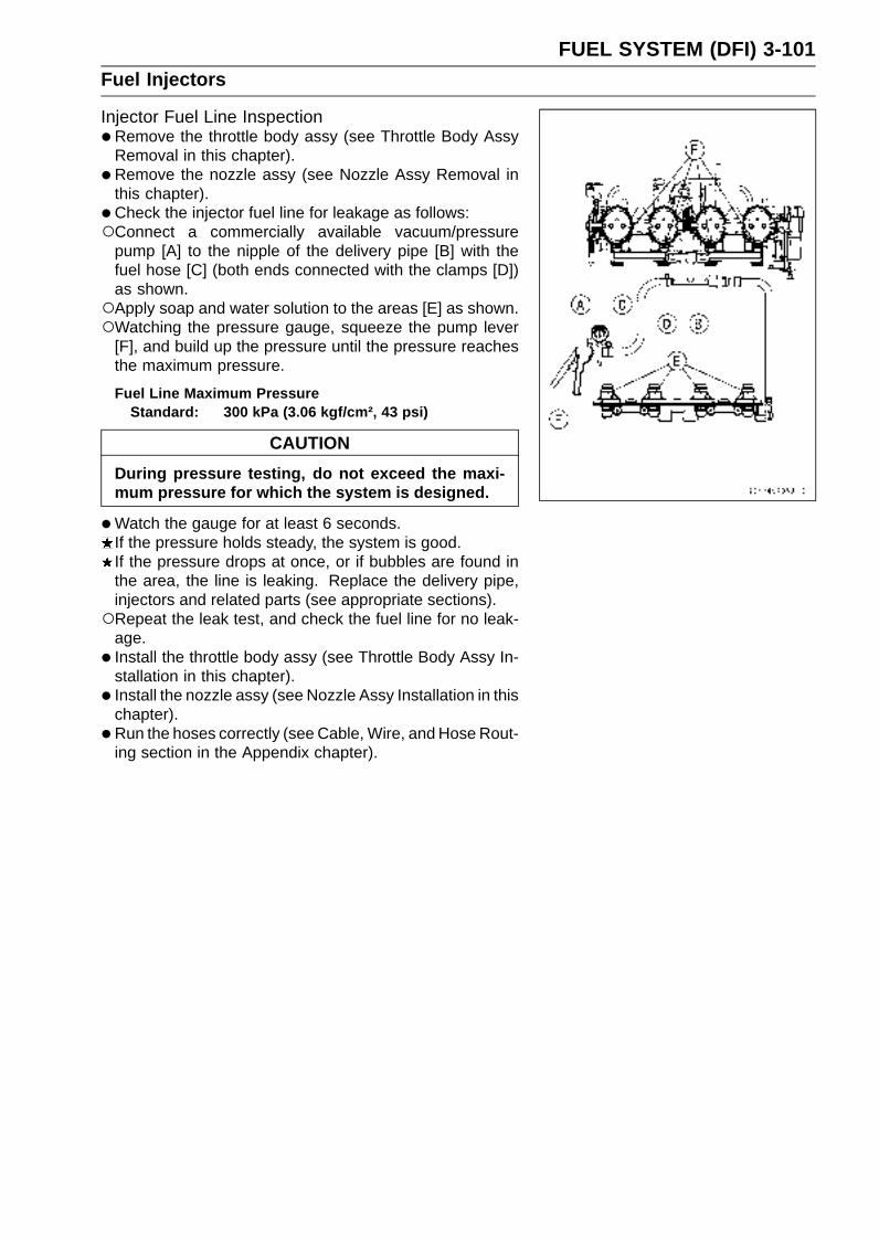
FUEL SYSTEM (DFI) 3-101Fuel Injectors
Injector Fuel Line Inspection•Remove the throttle body assy (see Throttle Body Assy
Removal in this chapter).
• Remove the nozzle assy (see Nozzle Assy Removal inthis chapter).
• Check the injector fuel line for leakage as follows:Connect a commercially available vacuum/pressure
pump [A] to the nipple of the delivery pipe [B] with thefuel hose [C] (both ends connected with the clamps [D])as shown.Apply soap and water solution to the areas [E] as shown.Watching the pressure gauge, squeeze the pump lever
[F], and build up the pressure until the pressure reachesthe maximum pressure.
Fuel Line Maximum PressureStandard: 300 kPa (3.06 kgf/cm², 43 psi)
CAUTION
During pressure testing, do not exceed the maxi-mum pressure for which the system is designed.
•Watch the gauge for at least 6 seconds.If the pressure holds steady, the system is good.If the pressure drops at once, or if bubbles are found inthe area, the line is leaking. Replace the delivery pipe,injectors and related parts (see appropriate sections).Repeat the leak test, and check the fuel line for no leak-
age.
• Install the throttle body assy (see Throttle Body Assy In-stallation in this chapter).
• Install the nozzle assy (see Nozzle Assy Installation in thischapter).
• Run the hoses correctly (see Cable, Wire, and Hose Rout-ing section in the Appendix chapter).

3-102 FUEL SYSTEM (DFI)Fuel Injectors
1. ECU2. Secondary Fuel Injector #43. Secondary Fuel Injector #34. Secondary Fuel Injector #25. Secondary Fuel Injector #16. Primary Fuel Injector #47. Primary Fuel Injector #38. Primary Fuel Injector #29. Primary Fuel Injector #1
10. Ignition Switch11. ECU Main Relay12. Fuel Pump Relay13. ECU Fuse 15 A14. Main Fuse 30 A15. Starter Relay16. Battery 12 V 8 Ah17. Engine Stop Switch18. Ignition Fuse 10 A19. Fuse Box20. Relay Box
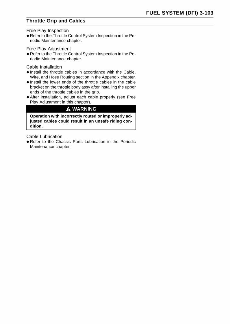
FUEL SYSTEM (DFI) 3-103Throttle Grip and Cables
Free Play Inspection•Refer to the Throttle Control System Inspection in the Pe-
riodic Maintenance chapter.
Free Play Adjustment•Refer to the Throttle Control System Inspection in the Pe-
riodic Maintenance chapter.
Cable Installation• Install the throttle cables in accordance with the Cable,
Wire, and Hose Routing section in the Appendix chapter.
• Install the lower ends of the throttle cables in the cablebracket on the throttle body assy after installing the upperends of the throttle cables in the grip.
• After installation, adjust each cable properly (see FreePlay Adjustment in this chapter).
WARNINGOperation with incorrectly routed or improperly ad-justed cables could result in an unsafe riding con-dition.
Cable Lubrication•Refer to the Chassis Parts Lubrication in the Periodic
Maintenance chapter.
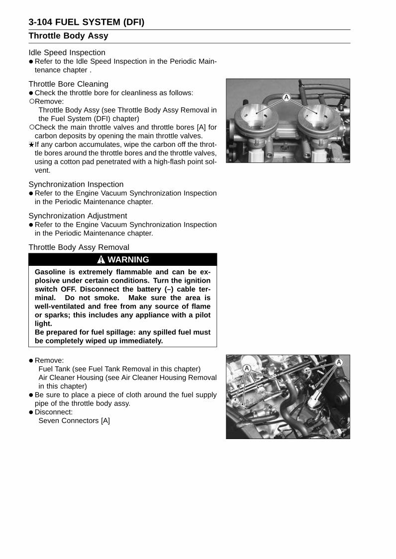
3-104 FUEL SYSTEM (DFI)Throttle Body Assy
Idle Speed Inspection•Refer to the Idle Speed Inspection in the Periodic Main-
tenance chapter .
Throttle Bore Cleaning•Check the throttle bore for cleanliness as follows:Remove:
Throttle Body Assy (see Throttle Body Assy Removal inthe Fuel System (DFI) chapter)
Check the main throttle valves and throttle bores [A] forcarbon deposits by opening the main throttle valves.If any carbon accumulates, wipe the carbon off the throt-tle bores around the throttle bores and the throttle valves,using a cotton pad penetrated with a high-flash point sol-vent.
Synchronization Inspection•Refer to the Engine Vacuum Synchronization Inspection
in the Periodic Maintenance chapter.
Synchronization Adjustment•Refer to the Engine Vacuum Synchronization Inspection
in the Periodic Maintenance chapter.
Throttle Body Assy Removal
WARNINGGasoline is extremely flammable and can be ex-plosive under certain conditions. Turn the ignitionswitch OFF. Disconnect the battery (–) cable ter-minal. Do not smoke. Make sure the area iswell-ventilated and free from any source of flameor sparks; this includes any appliance with a pilotlight.Be prepared for fuel spillage: any spilled fuel mustbe completely wiped up immediately.
•Remove:Fuel Tank (see Fuel Tank Removal in this chapter)Air Cleaner Housing (see Air Cleaner Housing Removalin this chapter)
• Be sure to place a piece of cloth around the fuel supplypipe of the throttle body assy.
•Disconnect:Seven Connectors [A]
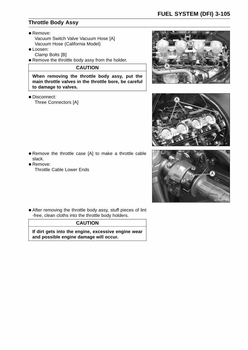
FUEL SYSTEM (DFI) 3-105Throttle Body Assy
•Remove:Vacuum Switch Valve Vacuum Hose [A]Vacuum Hose (California Model)
• Loosen:Clamp Bolts [B]
•Remove the throttle body assy from the holder.
CAUTION
When removing the throttle body assy, put themain throttle valves in the throttle bore, be carefulto damage to valves.
•Disconnect:Three Connectors [A]
•Remove the throttle case [A] to make a throttle cableslack.
•Remove:Throttle Cable Lower Ends
•After removing the throttle body assy, stuff pieces of lint-free, clean cloths into the throttle body holders.
CAUTION
If dirt gets into the engine, excessive engine wearand possible engine damage will occur.

3-106 FUEL SYSTEM (DFI)Throttle Body Assy
Throttle Body Assy Installation• Install the holder clamp bolts [A] in the direction as shown.
Bolt Heads [B]
• Install the lower ends of the throttle cables in the throttlebody assy, and install the throttle body assy.
CAUTION
When installing the throttle body assy, put the mainthrottle valves in the throttle bore, be careful todamage to valves.
•Tighten:Torque - Throttle Body Assembly Holder Clamp Bolts: 3.0
N·m (0.30 kgf·m, 27 in·lb)
• Install the removed connectors.
•Run the vacuum hoses as shown in the Cable, Wire, andHose Routing section in the Appendix chapter.
•When installing the fuel hose, refer to Fuel Tank Installa-tion in this chapter.
• Adjust:Throttle Grip Free Play (see Throttle Control System In-spection in the Periodic Maintenance chapter)Idle Speed (see Idle Speed Adjustment in the PeriodicMaintenance chapter)
Throttle Body Assy Disassembly
1. Subthrottle Valve Actuator2. Subthrottle Valve Sensor3. Main Throttle Valve Sensor4. Throttle Body Assy5. Injector6. Delivery Pipe Assy

FUEL SYSTEM (DFI) 3-107Throttle Body Assy
CAUTION
Do not remove, disassemble or adjust the mainthrottle sensor, subthrottle sensor, subthrottlevalve actuator, throttle link mechanism and throttlebody assy, because they are adjust or set surely atthe manufacturer. Adjustment of these parts couldresult in poor performance, requiring replacementof the throttle body assy.
•Remove the throttle body assy (see Throttle Body AssyRemoval in this chapter).
• Remove the injector connectors.
•Remove the screws [A] to pull out the injector assys fromthe throttle body assy together with the delivery pipe [B].
NOTEDo not damage the part of insert of the injectors when
they are pulled out from the throttle body.
•Pull out the injectors [A] from the delivery pipe [B].
NOTEDo not damage the part of insert of the injectors when
they are pulled out from the delivery pipe.
Throttle Body Assy Assembly•Before assembling, blow away dirt or dust from the throttle
body and delivery pipe by applying compressed air.
• Apply engine oil to the new O-rings [A] of each injector,insert them to the delivery pipe [B] and confirm whetherthe injectors turn smoothly or not.
NOTEReplace the O-ring of injectors and the dust seals of
delivery pipe to new one.
•Apply engine oil to the new dust seals [A], insert the in-jectors installed to the delivery pipe to the throttle body.
NOTEReplace the dust seals of the throttle body to new one.
• Install the delivery pipe assy to the throttle body.Torque - Delivery Pipe Mounting Screws: 3.4 N·m (0.35
kgf·m, 30 in·lb)
• Install the injector connectors to each injector.
• Insert the each hoses to the throttle body fittings.
• Install the throttle body assy (see Throttle Body Assy In-stallation in this chapter).

3-108 FUEL SYSTEM (DFI)Nozzle Assy
Nozzle Assy Removal•Remove:
Fuel Tank (see Fuel Tank Removal in this chapter)Nozzle Assy Lead Connectors [A]Fuel Hose [B]Nozzle Assy Mounting Bolts [C]Nozzle Assy [D]
WARNINGBe prepared for fuel spillage; any spilled fuel mustbe completely wiped up immediately.When the fuel hose is disconnected, fuel spills outfrom the hose and the pipe because of residualpressure. Cover the hose connection with a pieceof clean cloth to prevent fuel spillage.
Nozzle Assy Installation• Install the nozzle assy.
Torque - Nozzle Assy Mounting Bolts: 6.9 N·m (0.70 kgf·m,61 in·lb)
• Install:Nozzle Assy Lead ConnectorsFuel Hose (see Air Cleaner Housing Installation in thischapter)
WARNINGMake sure the hose joint is installed correctly on thedelivery pipe by sliding the joint, or the fuel couldleak.
Nozzle Assy Disassembly•Remove the nozzle assy (see Nozzle Assy Removal in
this chapter).
• Remove the screws [A] to pull out the injector assys fromthe stay plate comp together with the delivery pipe assy.
NOTEDo not damage the part of insert of the injectors when
they are pulled out from the stay plate comp.
•Remove the fuel hose.
• Pull out the injectors from the delivery pipe assy.
NOTEDo not damage the part of insert of the injectors when
they are pulled out from the delivery pipe assy.
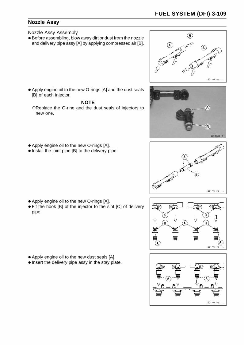
FUEL SYSTEM (DFI) 3-109Nozzle Assy
Nozzle Assy Assembly•Before assembling, blow away dirt or dust from the nozzle
and delivery pipe assy [A] by applying compressed air [B].
• Apply engine oil to the new O-rings [A] and the dust seals[B] of each injector.
NOTEReplace the O-ring and the dust seals of injectors to
new one.
•Apply engine oil to the new O-rings [A].
• Install the joint pipe [B] to the delivery pipe.
• Apply engine oil to the new O-rings [A].
• Fit the hook [B] of the injector to the slot [C] of deliverypipe.
• Apply engine oil to the new dust seals [A].
• Insert the delivery pipe assy in the stay plate.

3-110 FUEL SYSTEM (DFI)Nozzle Assy
•Tighten the screws [A].Torque - Delivery Pipe Mounting Screws: 3.4 N·m (0.35
kgf·m, 30 in·lb)
Stay Plate [B]
• Apply engine oil to the O-ring [A].
• Tighten:Torque - Fuel Hose Mounting Screw [B]: 4.9 N·m (0.50
kgf·m, 43 in·lb)
•Check the injector fuel line for leakage (see Injector FuelLine Inspection in this chapter).
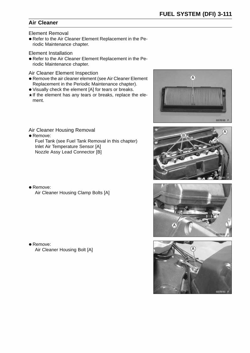
FUEL SYSTEM (DFI) 3-111Air Cleaner
Element Removal•Refer to the Air Cleaner Element Replacement in the Pe-
riodic Maintenance chapter.
Element Installation•Refer to the Air Cleaner Element Replacement in the Pe-
riodic Maintenance chapter.
Air Cleaner Element Inspection•Remove the air cleaner element (see Air Cleaner Element
Replacement in the Periodic Maintenance chapter).
• Visually check the element [A] for tears or breaks.If the element has any tears or breaks, replace the ele-ment.
Air Cleaner Housing Removal•Remove:
Fuel Tank (see Fuel Tank Removal in this chapter)Inlet Air Temperature Sensor [A]Nozzle Assy Lead Connector [B]
•Remove:Air Cleaner Housing Clamp Bolts [A]
•Remove:Air Cleaner Housing Bolt [A]
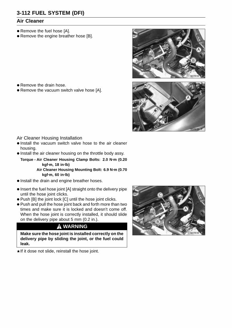
3-112 FUEL SYSTEM (DFI)Air Cleaner
•Remove the fuel hose [A].
• Remove the engine breather hose [B].
• Remove the drain hose.
•Remove the vacuum switch valve hose [A].
Air Cleaner Housing Installation• Install the vacuum switch valve hose to the air cleaner
housing.
• Install the air cleaner housing on the throttle body assy.Torque - Air Cleaner Housing Clamp Bolts: 2.0 N·m (0.20
kgf·m, 18 in·lb)Air Cleaner Housing Mounting Bolt: 6.9 N·m (0.70
kgf·m, 60 in·lb)
• Install the drain and engine breather hoses.
• Insert the fuel hose joint [A] straight onto the delivery pipeuntil the hose joint clicks.
• Push [B] the joint lock [C] until the hose joint clicks.
• Push and pull the hose joint back and forth more than twotimes and make sure it is locked and doesn’t come off.When the hose joint is correctly installed, it should slideon the delivery pipe about 5 mm (0.2 in.).
WARNINGMake sure the hose joint is installed correctly on thedelivery pipe by sliding the joint, or the fuel couldleak.
If it dose not slide, reinstall the hose joint.
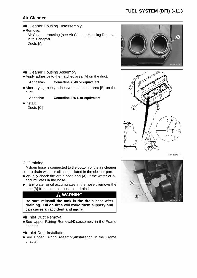
FUEL SYSTEM (DFI) 3-113Air Cleaner
Air Cleaner Housing Disassembly•Remove:
Air Cleaner Housing (see Air Cleaner Housing Removalin this chapter)Ducts [A]
Air Cleaner Housing Assembly•Apply adhesive to the hatched area [A] on the duct.
Adhesive- Cemedine #540 or equivalent
•After drying, apply adhesive to all mesh area [B] on theduct.
Adhesive- Cemedine 366 L or equivalent
• Install:Ducts [C]
Oil DrainingA drain hose is connected to the bottom of the air cleaner
part to drain water or oil accumulated in the cleaner part.
• Visually check the drain hose end [A], if the water or oilaccumulates in the hose.If any water or oil accumulates in the hose , remove thetank [B] from the drain hose and drain it.
WARNINGBe sure reinstall the tank in the drain hose afterdraining. Oil on tires will make them slippery andcan cause an accident and injury.
Air Inlet Duct Removal•See Upper Fairing Removal/Disassembly in the Frame
chapter.
Air Inlet Duct Installation•See Upper Fairing Assembly/Installation in the Frame
chapter.

3-114 FUEL SYSTEM (DFI)Fuel Tank
Fuel Tank RemovalWARNING
Gasoline is extremely flammable and can be explo-sive under certain conditions. Make sure the areais well-ventilated and free from any source of flameor sparks; this includes any appliance with a pilotlight. Do not smoke. Turn the ignition switch OFF.Be prepared for fuel spillage; any spilled fuel mustbe completely wiped up immediately.
•Turn the ignition switch OFF.
•Remove:Front Seat (see Front Seat Removal in the Frame chap-ter)
•Disconnect the battery (–) terminal.
•Wait until the engine cools down.
•Remove:Fuel Tank Bolt [A]
•Remove:Fuel Tank Bolts [A] (Both Side)Fuel Tank Bolt [B]Drain HoseConnector [C]Fuel Return Hose (Red, California model only)Fuel Tank Breather Hose (Blue, California model only)
•Open the fuel tank cap [A] to lower the pressure in thetank.
•Draw the fuel out from the fuel tank with a commerciallyavailable pump [A].Use a soft plastic hose [B] as a pump inlet hose in order
to insert the hose smoothly.Put the hose through the fill opening [C] into the tank and
draw the fuel out.Front [D]
WARNINGThe fuel could not be removed completely from thefuel tank. Be careful for remained fuel spillage.
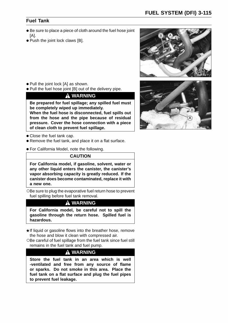
FUEL SYSTEM (DFI) 3-115Fuel Tank
•Be sure to place a piece of cloth around the fuel hose joint[A].
• Push the joint lock claws [B].
• Pull the joint lock [A] as shown.
• Pull the fuel hose joint [B] out of the delivery pipe.
WARNINGBe prepared for fuel spillage; any spilled fuel mustbe completely wiped up immediately.When the fuel hose is disconnected, fuel spills outfrom the hose and the pipe because of residualpressure. Cover the hose connection with a pieceof clean cloth to prevent fuel spillage.
•Close the fuel tank cap.
•Remove the fuel tank, and place it on a flat surface.
• For California Model, note the following.
CAUTION
For California model, if gasoline, solvent, water orany other liquid enters the canister, the canister’svapor absorbing capacity is greatly reduced. If thecanister does become contaminated, replace it witha new one.
Be sure to plug the evaporative fuel return hose to preventfuel spilling before fuel tank removal.
WARNINGFor California model, be careful not to spill thegasoline through the return hose. Spilled fuel ishazardous.
If liquid or gasoline flows into the breather hose, removethe hose and blow it clean with compressed air.Be careful of fuel spillage from the fuel tank since fuel still
remains in the fuel tank and fuel pump.
WARNINGStore the fuel tank in an area which is well-ventilated and free from any source of flameor sparks. Do not smoke in this area. Place thefuel tank on a flat surface and plug the fuel pipesto prevent fuel leakage.
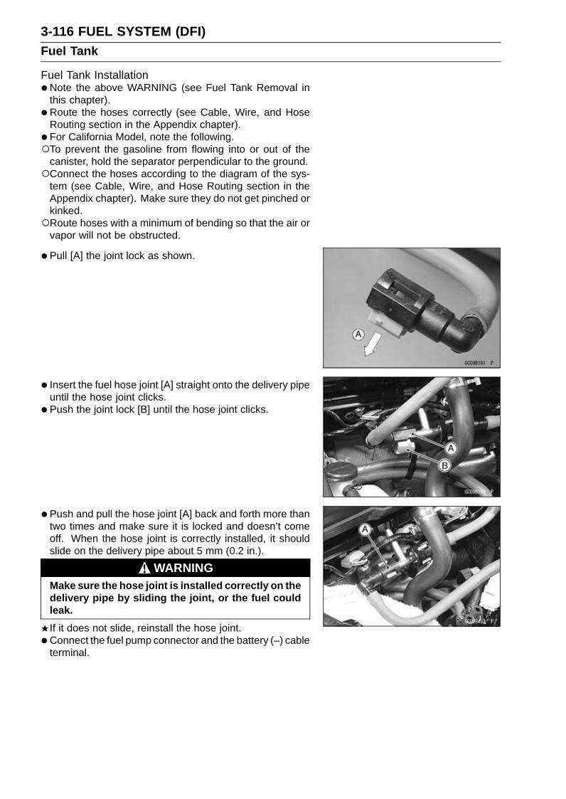
3-116 FUEL SYSTEM (DFI)Fuel Tank
Fuel Tank Installation•Note the above WARNING (see Fuel Tank Removal in
this chapter).
• Route the hoses correctly (see Cable, Wire, and HoseRouting section in the Appendix chapter).
• For California Model, note the following.To prevent the gasoline from flowing into or out of the
canister, hold the separator perpendicular to the ground.Connect the hoses according to the diagram of the sys-
tem (see Cable, Wire, and Hose Routing section in theAppendix chapter). Make sure they do not get pinched orkinked.Route hoses with a minimum of bending so that the air or
vapor will not be obstructed.
• Pull [A] the joint lock as shown.
• Insert the fuel hose joint [A] straight onto the delivery pipeuntil the hose joint clicks.
• Push the joint lock [B] until the hose joint clicks.
• Push and pull the hose joint [A] back and forth more thantwo times and make sure it is locked and doesn’t comeoff. When the hose joint is correctly installed, it shouldslide on the delivery pipe about 5 mm (0.2 in.).
WARNINGMake sure the hose joint is installed correctly on thedelivery pipe by sliding the joint, or the fuel couldleak.
If it does not slide, reinstall the hose joint.
• Connect the fuel pump connector and the battery (–) cableterminal.

FUEL SYSTEM (DFI) 3-117Fuel Tank
Fuel Tank and Cap Inspection•Visually inspect the gasket [A] on the tank cap for any
damage.Replace the gasket if it is damaged.
•Check to see if the water drain pipe [B] and fuel breatherpipe [C] (California Model) in the tank are not clogged.Check the tank cap breather also.If they are clogged, remove the tank and drain it, and thenblow the breather free with compressed air.
CAUTION
Do not apply compressed air to the air vent holes[D] in the tank cap. This could cause damage andclogging of the labyrinth in the cap.
Fuel Tank Cleaning
WARNINGClean the tank in a well-ventilated area, and takecare that there are no sparks or flame anywherenear the working area. Because of the danger orhighly flammable liquids, do not use gasoline orlow-flash point solvents to clean the tank.
•Remove the fuel tank (see Fuel Tank Removal in thischapter).
• Remove the fuel pump (see Fuel Pump Removal in thischapter).
• Pour some high-flash point solvent into the fuel tank andshake the tank to remove dirt and fuel deposits.
• Draw the solvent out of the fuel tank.
•Dry the tank with compressed air.
• Install the fuel pump (see Fuel Pump Installation in thischapter).
• Install the fuel tank (see Fuel Tank Installation in this chap-ter).

3-118 FUEL SYSTEM (DFI)Evaporative Emission Control System (California Model)
The Evaporative Emission Control System routes fuel va-pors from the fuel system into the running engine or storesthe vapors in a canister when the engine is stopped. Al-though no adjustments are required, a thorough visual in-spection must be made at the intervals specified by the Pe-riodic Maintenance Chart.
Parts Removal/InstallationWARNING
Gasoline is extremely flammable and can be ex-plosive under certain conditions. Turn the ignitionswitch OFF. Do not smoke. Make sure the area iswell-ventilated and free from any source of flameor sparks; this includes any appliance with a pilotlight.
CAUTION
If gasoline, solvent, water or any other liquid entersthe canister, the canister’s vapor absorbing capac-ity is greatly reduced. If the canister does becomecontaminated, replace it with a new one.
•To prevent the gasoline from flowing into or out of thecanister, hold the separator perpendicular to the ground.
•Connect the hoses according to the diagram of the sys-tem (see Cable, Wire, and Hose Routing section in theAppendix chapter). Make sure they do not get pinched orkinked.
Hose Inspection•Refer to the Evaporative Emission Control System In-
spection in the Periodic Maintenance chapter.
Separator Inspection•Refer to the Evaporative Emission Control System In-
spection in the Periodic Maintenance chapter.Separator [A]
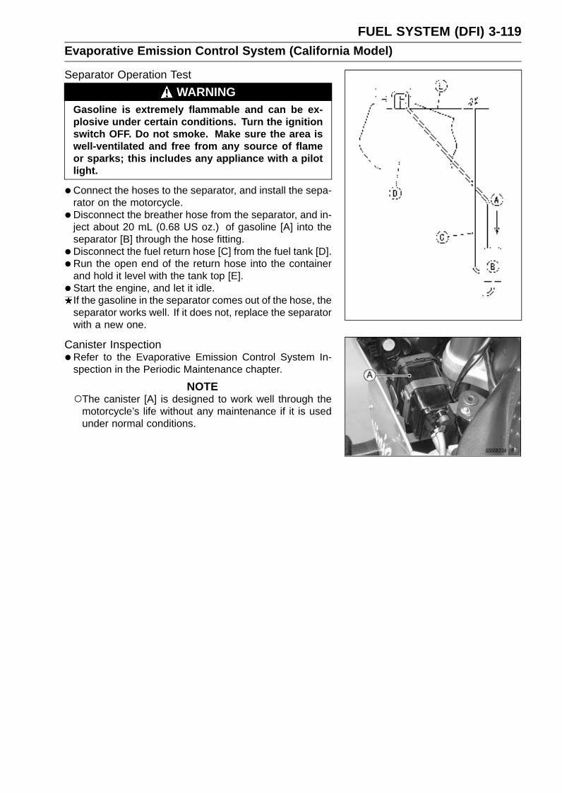
FUEL SYSTEM (DFI) 3-119Evaporative Emission Control System (California Model)
Separator Operation Test
WARNINGGasoline is extremely flammable and can be ex-plosive under certain conditions. Turn the ignitionswitch OFF. Do not smoke. Make sure the area iswell-ventilated and free from any source of flameor sparks; this includes any appliance with a pilotlight.
•Connect the hoses to the separator, and install the sepa-rator on the motorcycle.
•Disconnect the breather hose from the separator, and in-ject about 20 mL (0.68 US oz.) of gasoline [A] into theseparator [B] through the hose fitting.
•Disconnect the fuel return hose [C] from the fuel tank [D].
• Run the open end of the return hose into the containerand hold it level with the tank top [E].
• Start the engine, and let it idle.If the gasoline in the separator comes out of the hose, theseparator works well. If it does not, replace the separatorwith a new one.
Canister Inspection•Refer to the Evaporative Emission Control System In-
spection in the Periodic Maintenance chapter.
NOTEThe canister [A] is designed to work well through the
motorcycle’s life without any maintenance if it is usedunder normal conditions.

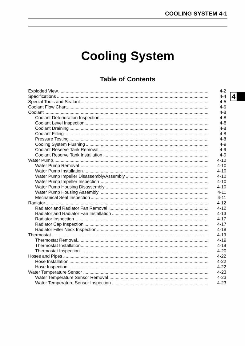
COOLING SYSTEM 4-1
4
Cooling System
Table of Contents
Exploded View........................................................................................................................ 4-2Specifications ......................................................................................................................... 4-4Special Tools and Sealant ...................................................................................................... 4-5Coolant Flow Chart................................................................................................................. 4-6Coolant ................................................................................................................................... 4-8
Coolant Deterioration Inspection....................................................................................... 4-8Coolant Level Inspection................................................................................................... 4-8Coolant Draining ............................................................................................................... 4-8Coolant Filling ................................................................................................................... 4-8Pressure Testing ............................................................................................................... 4-8Cooling System Flushing .................................................................................................. 4-9Coolant Reserve Tank Removal ....................................................................................... 4-9Coolant Reserve Tank Installation .................................................................................... 4-9
Water Pump............................................................................................................................ 4-10Water Pump Removal....................................................................................................... 4-10Water Pump Installation.................................................................................................... 4-10Water Pump Impeller Disassembly/Assembly .................................................................. 4-10Water Pump Impeller Inspection....................................................................................... 4-10Water Pump Housing Disassembly .................................................................................. 4-10Water Pump Housing Assembly ....................................................................................... 4-11Mechanical Seal Inspection .............................................................................................. 4-11
Radiator .................................................................................................................................. 4-12Radiator and Radiator Fan Removal ................................................................................ 4-12Radiator and Radiator Fan Installation ............................................................................. 4-13Radiator Inspection ........................................................................................................... 4-17Radiator Cap Inspection ................................................................................................... 4-17Radiator Filler Neck Inspection ......................................................................................... 4-18
Thermostat ............................................................................................................................. 4-19Thermostat Removal......................................................................................................... 4-19Thermostat Installation...................................................................................................... 4-19Thermostat Inspection ...................................................................................................... 4-20
Hoses and Pipes .................................................................................................................... 4-22Hose Installation ............................................................................................................... 4-22Hose Inspection ................................................................................................................ 4-22
Water Temperature Sensor .................................................................................................... 4-23Water Temperature Sensor Removal................................................................................ 4-23Water Temperature Sensor Inspection ............................................................................. 4-23
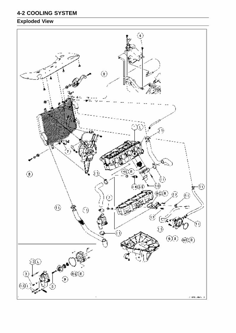
4-2 COOLING SYSTEMExploded View
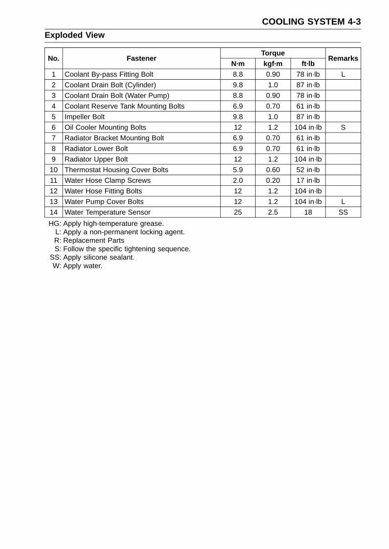
COOLING SYSTEM 4-3Exploded View
TorqueNo. Fastener
N·m kgf·m ft·lbRemarks
1 Coolant By-pass Fitting Bolt 8.8 0.90 78 in·lb L
2 Coolant Drain Bolt (Cylinder) 9.8 1.0 87 in·lb
3 Coolant Drain Bolt (Water Pump) 8.8 0.90 78 in·lb
4 Coolant Reserve Tank Mounting Bolts 6.9 0.70 61 in·lb
5 Impeller Bolt 9.8 1.0 87 in·lb
6 Oil Cooler Mounting Bolts 12 1.2 104 in·lb S
7 Radiator Bracket Mounting Bolt 6.9 0.70 61 in·lb
8 Radiator Lower Bolt 6.9 0.70 61 in·lb
9 Radiator Upper Bolt 12 1.2 104 in·lb
10 Thermostat Housing Cover Bolts 5.9 0.60 52 in·lb
11 Water Hose Clamp Screws 2.0 0.20 17 in·lb
12 Water Hose Fitting Bolts 12 1.2 104 in·lb
13 Water Pump Cover Bolts 12 1.2 104 in·lb L
14 Water Temperature Sensor 25 2.5 18 SS
HG: Apply high-temperature grease.L: Apply a non-permanent locking agent.R: Replacement PartsS: Follow the specific tightening sequence.
SS: Apply silicone sealant.W: Apply water.
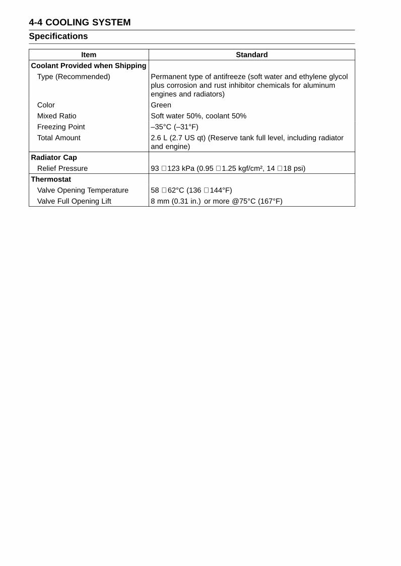
4-4 COOLING SYSTEMSpecifications
Item StandardCoolant Provided when Shipping
Type (Recommended) Permanent type of antifreeze (soft water and ethylene glycolplus corrosion and rust inhibitor chemicals for aluminumengines and radiators)
Color Green
Mixed Ratio Soft water 50%, coolant 50%
Freezing Point –35°C (–31°F)
Total Amount 2.6 L (2.7 US qt) (Reserve tank full level, including radiatorand engine)
Radiator CapRelief Pressure 93 ∼ 123 kPa (0.95 ∼ 1.25 kgf/cm², 14 ∼ 18 psi)
ThermostatValve Opening Temperature 58 ∼ 62°C (136 ∼ 144°F)
Valve Full Opening Lift 8 mm (0.31 in.) or more @75°C (167°F)

COOLING SYSTEM 4-5Special Tools and Sealant
Bearing Driver, 32:57001-382
Bearing Driver Set:57001-1129
Kawasaki Bond (Silicone Sealant):56019-120
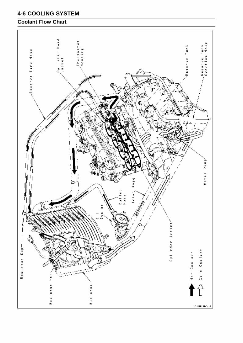
4-6 COOLING SYSTEMCoolant Flow Chart

COOLING SYSTEM 4-7Coolant Flow Chart
Permanent type antifreeze is used as a coolant to protect the cooling system from rust and corrosion.When the engine starts, the water pump turns and the coolant circulates.
The thermostat is a wax pellet type which opens or closes with coolant temperature changes. Thethermostat continuously changes its valve opening to keep the coolant temperature at the proper level.When coolant temperature is less than 55°C (131°F), the thermostat closes so that the coolant flowis restricted through the air bleeder hole, causing the engine to warm up more quickly. When coolanttemperature is more than 58 ∼ 62°C (136 ∼ 144°F), the thermostat opens and the coolant flows.
When the coolant temperature goes up beyond 95°C (203°F), the radiator fan relay conducts to op-erate the radiator fan. The radiator fan draws air through the radiator core when there is not sufficientair flow such as at low speeds. This increases up the cooling action of the radiator. When the coolanttemperature is below 90°C (194°F), the fan relay opens and the radiator fan stops.
In this way, this system controls the engine temperature within narrow limits where the engine op-erates most efficiently even if the engine load varies.
The system is pressurized by the radiator cap to suppress boiling and the resultant air bubbleswhich can cause engine overheating. As the engine warms up, the coolant in the radiator and thewater jacket expands. The excess coolant flows through the radiator cap and hose to the reserve tankto be stored there temporarily. Conversely, as the engine cools down, the coolant in the radiator andthe water jacket contracts, and the stored coolant flows back to the radiator from the reserve tank.
The radiator cap has two valves. One is a pressure valve which holds the pressure in the systemwhen the engine is running. When the pressure exceeds 93 ∼ 123 kPa (0.95 ∼ 1.25 kgf/cm², 14 ∼ 18psi), the pressure valve opens and releases the pressure to the reserve tank. As soon as pressureescapes, the valve closes, and keeps the pressure at 93 ∼ 123 kPa (0.95 ∼ 1.25 kgf/cm², 14 ∼ 18 psi).When the engine cools down, another small valve (vacuum valve) in the cap opens. As the coolantcools, the coolant contracts to form a vacuum in the system. The vacuum valve opens and allows thecoolant from the reserve tank to enter the radiator.
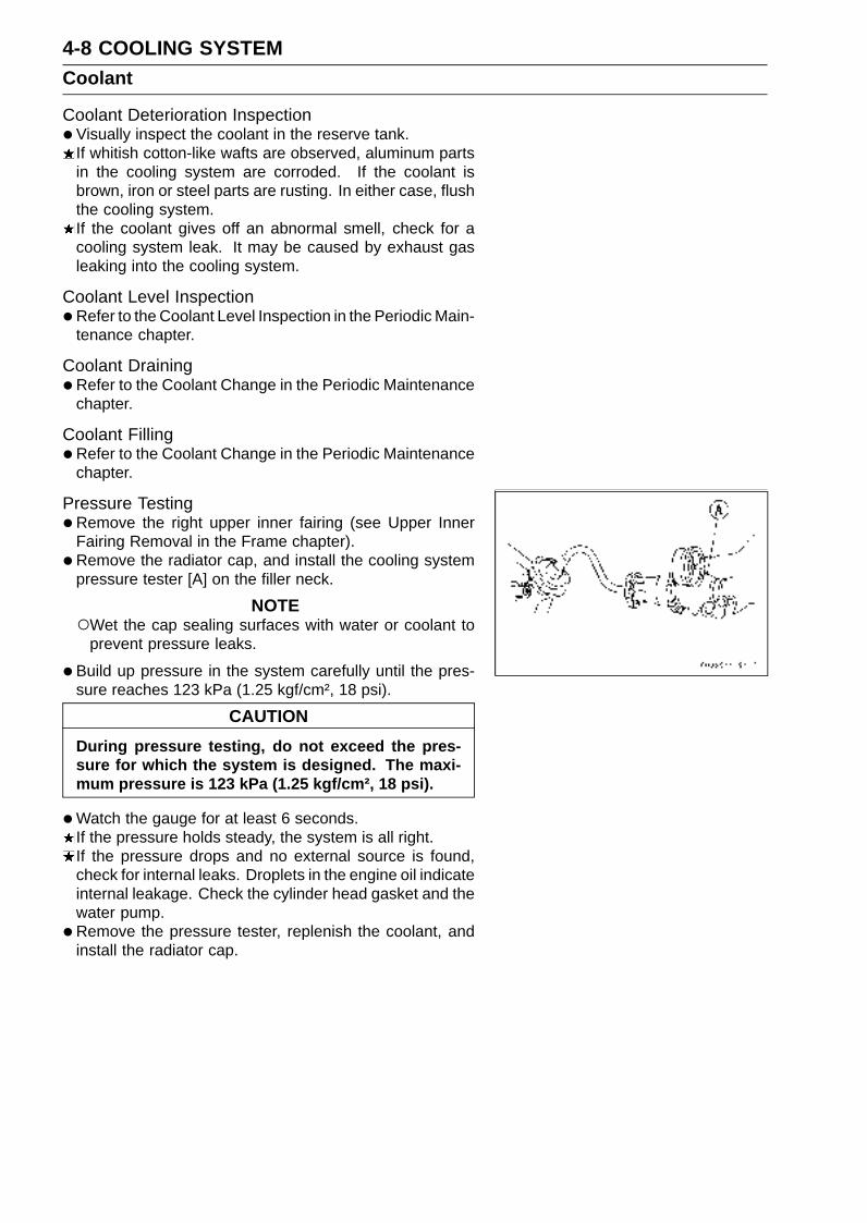
4-8 COOLING SYSTEMCoolant
Coolant Deterioration Inspection•Visually inspect the coolant in the reserve tank.
If whitish cotton-like wafts are observed, aluminum partsin the cooling system are corroded. If the coolant isbrown, iron or steel parts are rusting. In either case, flushthe cooling system.If the coolant gives off an abnormal smell, check for acooling system leak. It may be caused by exhaust gasleaking into the cooling system.
Coolant Level Inspection•Refer to the Coolant Level Inspection in the Periodic Main-
tenance chapter.
Coolant Draining•Refer to the Coolant Change in the Periodic Maintenance
chapter.
Coolant Filling•Refer to the Coolant Change in the Periodic Maintenance
chapter.
Pressure Testing•Remove the right upper inner fairing (see Upper Inner
Fairing Removal in the Frame chapter).
• Remove the radiator cap, and install the cooling systempressure tester [A] on the filler neck.
NOTEWet the cap sealing surfaces with water or coolant to
prevent pressure leaks.
•Build up pressure in the system carefully until the pres-sure reaches 123 kPa (1.25 kgf/cm², 18 psi).
CAUTION
During pressure testing, do not exceed the pres-sure for which the system is designed. The maxi-mum pressure is 123 kPa (1.25 kgf/cm², 18 psi).
•Watch the gauge for at least 6 seconds.If the pressure holds steady, the system is all right.If the pressure drops and no external source is found,check for internal leaks. Droplets in the engine oil indicateinternal leakage. Check the cylinder head gasket and thewater pump.
•Remove the pressure tester, replenish the coolant, andinstall the radiator cap.
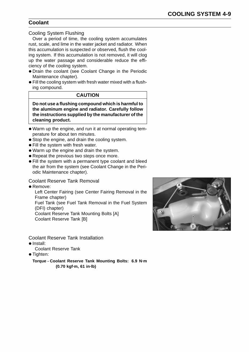
COOLING SYSTEM 4-9Coolant
Cooling System FlushingOver a period of time, the cooling system accumulates
rust, scale, and lime in the water jacket and radiator. Whenthis accumulation is suspected or observed, flush the cool-ing system. If this accumulation is not removed, it will clogup the water passage and considerable reduce the effi-ciency of the cooling system.
•Drain the coolant (see Coolant Change in the PeriodicMaintenance chapter).
• Fill the cooling system with fresh water mixed with a flush-ing compound.
CAUTION
Do not use a flushing compound which is harmful tothe aluminum engine and radiator. Carefully followthe instructions supplied by the manufacturer of thecleaning product.
•Warm up the engine, and run it at normal operating tem-perature for about ten minutes.
• Stop the engine, and drain the cooling system.
• Fill the system with fresh water.
•Warm up the engine and drain the system.
•Repeat the previous two steps once more.
• Fill the system with a permanent type coolant and bleedthe air from the system (see Coolant Change in the Peri-odic Maintenance chapter).
Coolant Reserve Tank Removal•Remove:
Left Center Fairing (see Center Fairing Removal in theFrame chapter)Fuel Tank (see Fuel Tank Removal in the Fuel System(DFI) chapter)Coolant Reserve Tank Mounting Bolts [A]Coolant Reserve Tank [B]
Coolant Reserve Tank Installation• Install:
Coolant Reserve Tank
• Tighten:
Torque - Coolant Reserve Tank Mounting Bolts: 6.9 N·m(0.70 kgf·m, 61 in·lb)
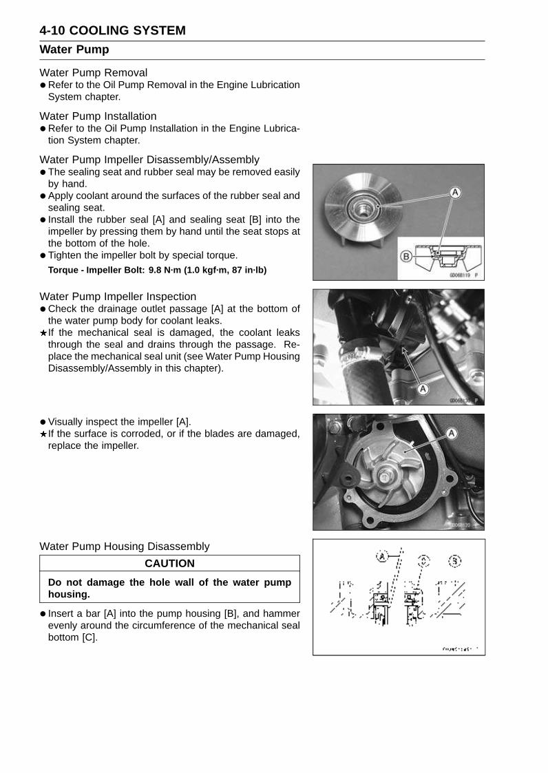
4-10 COOLING SYSTEMWater Pump
Water Pump Removal•Refer to the Oil Pump Removal in the Engine Lubrication
System chapter.
Water Pump Installation•Refer to the Oil Pump Installation in the Engine Lubrica-
tion System chapter.
Water Pump Impeller Disassembly/Assembly•The sealing seat and rubber seal may be removed easily
by hand.
• Apply coolant around the surfaces of the rubber seal andsealing seat.
• Install the rubber seal [A] and sealing seat [B] into theimpeller by pressing them by hand until the seat stops atthe bottom of the hole.
• Tighten the impeller bolt by special torque.Torque - Impeller Bolt: 9.8 N·m (1.0 kgf·m, 87 in·lb)
Water Pump Impeller Inspection•Check the drainage outlet passage [A] at the bottom of
the water pump body for coolant leaks.If the mechanical seal is damaged, the coolant leaksthrough the seal and drains through the passage. Re-place the mechanical seal unit (see Water Pump HousingDisassembly/Assembly in this chapter).
• Visually inspect the impeller [A].If the surface is corroded, or if the blades are damaged,replace the impeller.
Water Pump Housing Disassembly
CAUTION
Do not damage the hole wall of the water pumphousing.
• Insert a bar [A] into the pump housing [B], and hammerevenly around the circumference of the mechanical sealbottom [C].

COOLING SYSTEM 4-11Water Pump
•Take the oil seal [A] out of the housing [B] with a hook [C].
Water Pump Housing Assembly
CAUTION
Do not reuse the mechanical seal and oil seal.
•Apply high-temperature grease to the oil seal lips [A].
• Press the new oil seal into the housing with a bearingdriver [B] until it stops at the bottom surface [C] of thehousing.Special Tool - Bearing Driver Set: 57001-1129
CAUTION
Be careful not to damage the sealing surface of themechanical seal.
•Press the new mechanical seal into the housing with stembearing driver [A] until its flange [B] touches the surface[C] of the housing.
Special Tool - Bearing Driver, 32: 57001-382
Mechanical Seal Inspection•Visually inspect the mechanical seal.
If any one of the parts is damaged, replace the mechani-cal seal as a unit.Impeller Sealing Seat Surface [A]Rubber Seal [B]Mechanical Seal [C]

4-12 COOLING SYSTEMRadiator
Radiator and Radiator Fan Removal•Remove:
Coolant (Drain, see Coolant Change in the PeriodicMaintenance chapter)Air Cleaner Housing (see Air Cleaner Housing Removalin the Fuel System (DFI) chapter)Radiator Fan Lead Connector [A]
•Remove:Bolt [A]
•Remove:Radiator Hoses [A]
•Remove:Radiator Hoses [A]Radiator Upper Bolt [B]
•Remove:Radiator Lower Bolt [A]Radiator Hose [B]
• Pull the radiator from the projection, and remove the ra-diator.
CAUTION
Do not touch the radiator core. This could damagethe radiator fins, resulting in loss of cooling effi-ciency.

COOLING SYSTEM 4-13Radiator
•Remove:Radiator Fan Mounting Bolts [A]Radiator Fan [B]
Radiator and Radiator Fan Installation• Insert the plugs [A] in the holes of heat insulation rubber
plate [B].
• Install the heat insulation rubber plate [C] on the engine.
• Install the plug in the clamp [A] of air suction valve cover.Front [B]

4-14 COOLING SYSTEMRadiator
•Cover [A] the heat insulation rubber plate on the radiator.
• Install the radiator to the projection [B] as shown.

COOLING SYSTEM 4-15Radiator
•Enchase the heat insulation rubber plate [A] to the radia-tor stay.
• Through the radiator fan lead [B] in the heat insulationrubber plate hole, and clamp the radiator fan lead andhorn lead [C] with the radiator clamp [D].
• Clamp the immobilizer antenna lead [E] and ignitionswitch lead [F].
• Enchase the heat insulation rubber plate to the radiatorcap [G].
•Hang down [H] the heat insulation rubber plate forward ofcylinder head cover.
• After the hang down, bend [I] the heat insulation rubberplate outside of engine mount, and insert the rivets [J](both side).
• Hang the hole [K] of heat insulation rubber plate to thetang [L] of the center fairing.

4-16 COOLING SYSTEMRadiator
• Install the radiator bracket collar [A] as shown.Rubber Damper [B]Radiator [C]Horn [D]Harness Stay [E]Bolt [F]
• Tighten:Torque - Radiator Upper Bolt [G]: 12 N·m (1.2 kgf·m, 104
in·lb)Radiator Lower Bolt [H]: 6.9 N·m (0.70 kgf·m, 61
in·lb)
• Install the water hose clamp [I].
• Tighten:Torque - Water Hose Clamp Screws: 2.0 N·m (0.20 kgf·m,
17 in·lb)
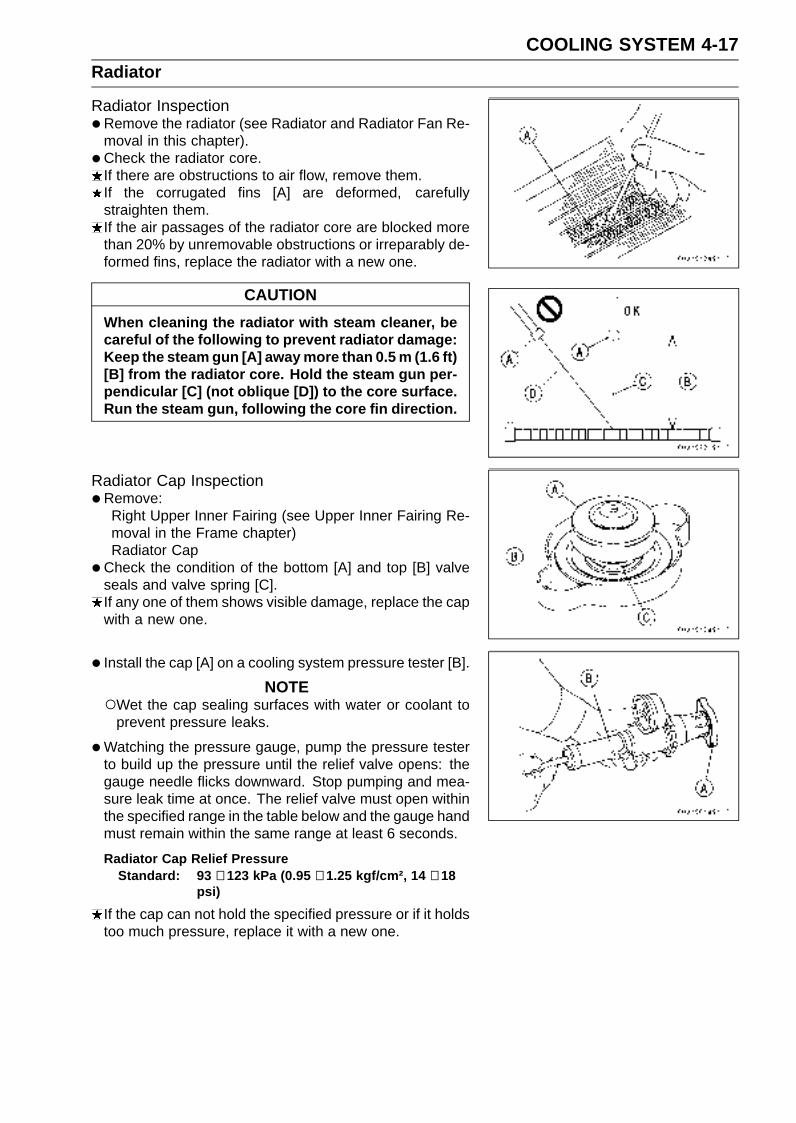
COOLING SYSTEM 4-17Radiator
Radiator Inspection•Remove the radiator (see Radiator and Radiator Fan Re-
moval in this chapter).
• Check the radiator core.If there are obstructions to air flow, remove them.If the corrugated fins [A] are deformed, carefullystraighten them.If the air passages of the radiator core are blocked morethan 20% by unremovable obstructions or irreparably de-formed fins, replace the radiator with a new one.
CAUTION
When cleaning the radiator with steam cleaner, becareful of the following to prevent radiator damage:Keep the steam gun [A] away more than 0.5 m (1.6 ft)[B] from the radiator core. Hold the steam gun per-pendicular [C] (not oblique [D]) to the core surface.Run the steam gun, following the core fin direction.
Radiator Cap Inspection•Remove:
Right Upper Inner Fairing (see Upper Inner Fairing Re-moval in the Frame chapter)Radiator Cap
•Check the condition of the bottom [A] and top [B] valveseals and valve spring [C].If any one of them shows visible damage, replace the capwith a new one.
• Install the cap [A] on a cooling system pressure tester [B].
NOTEWet the cap sealing surfaces with water or coolant to
prevent pressure leaks.
•Watching the pressure gauge, pump the pressure testerto build up the pressure until the relief valve opens: thegauge needle flicks downward. Stop pumping and mea-sure leak time at once. The relief valve must open withinthe specified range in the table below and the gauge handmust remain within the same range at least 6 seconds.
Radiator Cap Relief PressureStandard: 93 ∼ 123 kPa (0.95 ∼ 1.25 kgf/cm², 14 ∼ 18
psi)
If the cap can not hold the specified pressure or if it holdstoo much pressure, replace it with a new one.
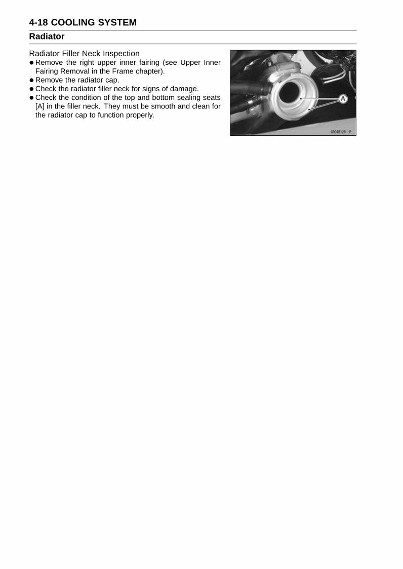
4-18 COOLING SYSTEMRadiator
Radiator Filler Neck Inspection•Remove the right upper inner fairing (see Upper Inner
Fairing Removal in the Frame chapter).
• Remove the radiator cap.
•Check the radiator filler neck for signs of damage.
•Check the condition of the top and bottom sealing seats[A] in the filler neck. They must be smooth and clean forthe radiator cap to function properly.

COOLING SYSTEM 4-19Thermostat
Thermostat Removal•Drain the coolant (see Coolant Change in the Periodic
Maintenance chapter).
• Remove:Fuel Tank (see Fuel Tank Removal in the Fuel System(DFI) chapter)Throttle Body Assy (see Throttle Body Assy Removal inthe Fuel System (DFI) chapter)Thermostat Housing Cover Bolts [A]Bracket [B]Thermostat Housing Cover [C]Thermostat
Thermostat Installation• Install the thermostat [A] in the housing so that the air
bleeder hole [B] is on top.
• Apply high-temperature grease to the new O-ring [A].
• Install a new O-ring into the housing cover.
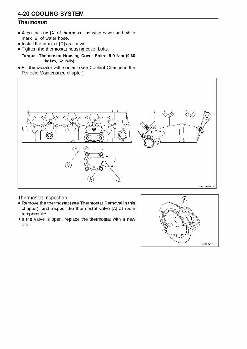
4-20 COOLING SYSTEMThermostat
•Align the line [A] of thermostat housing cover and whitemark [B] of water hose.
• Install the bracket [C] as shown.
• Tighten the thermostat housing cover bolts.Torque - Thermostat Housing Cover Bolts: 5.9 N·m (0.60
kgf·m, 52 in·lb)
•Fill the radiator with coolant (see Coolant Change in thePeriodic Maintenance chapter).
Thermostat Inspection•Remove the thermostat (see Thermostat Removal in this
chapter), and inspect the thermostat valve [A] at roomtemperature.If the valve is open, replace the thermostat with a newone.

COOLING SYSTEM 4-21Thermostat
•To check valve opening temperature, suspend the ther-mostat [A] in a container of water and raise the tempera-ture of the water.The thermostat must be completely submerged and must
not touch the container sides or bottom. Suspend an ac-curate thermometer [B] in the water so that the heat sen-sitive portions [C] are located in almost the same depth.It must not touch the container, either.If the measurement is out of the specified range, replacethe thermostat with a new one.
Thermostat Valve Opening Temperature58 ∼ 62°C (136 ∼ 144°F)

4-22 COOLING SYSTEMHoses and Pipes
Hose Installation• Install the hoses and pipes, being careful to follow bend-
ing direction. Avoid sharp bending, kinking, flattening ortwisting.
•Run the hoses in accordance with the Cable, Wire, andHose Routing section in the Appendix chapter.
• Install the clamp [A] as near as possible to the hose endto clear the raised rib of the fitting. This will prevent thehoses from working loose.The clamp screws should be positioned correctly to pre-
vent the clamps from contacting the other parts.Torque - Water Hose Clamp Screws: 2.0 N·m (0.20 kgf·m,
17 in·lb)
Hose Inspection•Refer to the Radiator Hose Damage and Installation Con-
dition Inspection in the Periodic Maintenance chapter.

COOLING SYSTEM 4-23Water Temperature Sensor
CAUTION
The water temperature sensor should never be al-lowed to fall on a hard surface. Such a shock totheir parts can damage them.
Water Temperature Sensor Removal•Refer to the Water Temperature Sensor Removal in the
Fuel System (DFI) chapter.Water Temperature Sensor [A]
Water Temperature Sensor Inspection•Refer to the Water Temperature Sensor Inspection in the
Electrical System chapter.

ENGINE TOP END 5-1
5
Engine Top End
Table of Contents
Exploded View................................... 5-2Specifications .................................... 5-7Special Tools and Sealant ................. 5-9Clean Air System............................... 5-11
Air Suction Valve Removal........... 5-11Air Suction Valve Installation........ 5-11Air Suction Valve Inspection ........ 5-11Vacuum Switch Valve Removal ... 5-11Vacuum Switch Valve Installation 5-12Vacuum Switch Valve Test ........... 5-12Clean Air System Hose
Inspection.................................. 5-12Cylinder Head Cover ......................... 5-13
Cylinder Head Cover Removal .... 5-13Cylinder Head Cover Installation . 5-13
Camshaft Chain Tensioner ................ 5-15Camshaft Chain Tensioner
Removal .................................... 5-15Camshaft Chain Tensioner
Installation ................................. 5-15Camshaft, Camshaft Chain ............... 5-16
Camshaft Removal ...................... 5-16Camshaft Installation ................... 5-16Camshaft, Camshaft Cap Wear ... 5-18Camshaft Runout ......................... 5-18Cam Wear.................................... 5-19Camshaft Chain Removal ............ 5-19
Cylinder Head.................................... 5-20Cylinder Compression
Measurement ............................ 5-20Cylinder Head Removal ............... 5-21Cylinder Head Installation ............ 5-21Cylinder Head Warp..................... 5-22
Valves ................................................ 5-23
Valve Clearance Inspection ......... 5-23Valve Clearance Adjustment........ 5-23Valve Removal ............................. 5-23Valve Installation .......................... 5-23Valve Guide Removal .................. 5-23Valve Guide Installation ............... 5-24Valve-to-Guide Clearance
Measurement (WobbleMethod) ..................................... 5-24
Valve Seat Inspection .................. 5-25Valve Seat Repair ........................ 5-25
Cylinder, Pistons................................ 5-30Cylinder Removal......................... 5-30Cylinder Installation...................... 5-30Piston Removal............................ 5-31Piston Installation......................... 5-31Cylinder Wear .............................. 5-32Piston Wear ................................. 5-32Piston Ring, Piston Ring Groove
Wear.......................................... 5-33Piston Ring Groove Width............ 5-33Piston Ring Thickness ................. 5-33Piston Ring End Gap ................... 5-34
Throttle Body Holder.......................... 5-35Throttle Body Holder Installation.. 5-35
Muffler................................................ 5-36Muffler Body Removal.................. 5-36Muffler Body Installation............... 5-38Exhaust Pipe Removal................. 5-39Exhaust Pipe Installation.............. 5-40Exhaust Butterfly Valve Cable
Removal .................................... 5-41Exhaust Butterfly Valve Cable
Installation ................................. 5-41

5-2 ENGINE TOP ENDExploded View

ENGINE TOP END 5-3Exploded View
TorqueNo. Fastener
N·m kgf·m ft·lbRemarks
1 Air Suction Valve Cover Bolts 12 1.2 104 in·lb L
2 Camshaft Cap Bolts 12 1.2 104 in·lb S
3 Camshaft Chain Tensioner Cap Bolt 20 2.0 15
4 Camshaft Chain Tensioner Mounting Bolts 11 1.1 97 in·lb
5 Cam Sprocket Mounting Bolts 15 1.5 11 L
6 Coolant Drain Bolt (Cylinder) 9.8 1.0 87 in·lb
7 Crankshaft Sensor Cover Bolts 9.8 1.0 87 in·lb L (1)
8 Cylinder Head Bolts (M9) 39 4.0 29 MO, S
9 Cylinder Head Bolts (M6) 12 1.2 104 in·lb S
10 Cylinder Head Cover Bolts 9.8 1.0 87 in·lb
11 Front Camshaft Chain Guide Bolt (Lower) 12 1.2 104 in·lb
12 Front Camshaft Chain Guide Bolt (Upper) 25 2.5 18
13 Rear Camshaft Chain Guide Bolt 25 2.5 18
14 Spark Plugs 13 1.3 113 in·lb
15 Throttle Body Assy Holder Clamp Bolts 2.9 0.30 26 in·lb
16 Throttle Body Holder Bolts 12 1.2 104 in·lb L
17 Water Passage Plug (Left) 20 2.0 15 L
18 Water Passage Plugs (Upper) 20 2.0 15 L
EO: Apply engine oil.G: Apply grease.
HG: Apply high-temperature grease.L: Apply a non-permanent locking agent.
M: Apply molybdenum disulfide grease.MO: Apply molybdenum disulfide oil solution.
(mixture of the engine oil and molybdenum disulfide grease in a weight ratio 10 : 1)R: Replacement PartsS: Follow the specific tightening sequence.
SS: Apply silicone sealant.
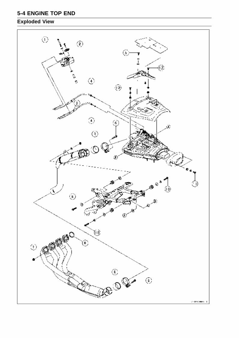
5-4 ENGINE TOP ENDExploded View
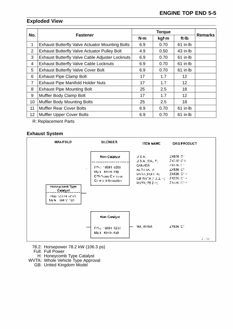
ENGINE TOP END 5-5Exploded View
TorqueNo. Fastener
N·m kgf·m ft·lbRemarks
1 Exhaust Butterfly Valve Actuator Mounting Bolts 6.9 0.70 61 in·lb
2 Exhaust Butterfly Valve Actuator Pulley Bolt 4.9 0.50 43 in·lb
3 Exhaust Butterfly Valve Cable Adjuster Locknuts 6.9 0.70 61 in·lb
4 Exhaust Butterfly Valve Cable Locknuts 6.9 0.70 61 in·lb
5 Exhaust Butterfly Valve Cover Bolt 6.9 0.70 61 in·lb
6 Exhaust Pipe Clamp Bolt 17 1.7 12
7 Exhaust Pipe Manifold Holder Nuts 17 1.7 12
8 Exhaust Pipe Mounting Bolt 25 2.5 18
9 Muffler Body Clamp Bolt 17 1.7 12
10 Muffler Body Mounting Bolts 25 2.5 18
11 Muffler Rear Cover Bolts 6.9 0.70 61 in·lb
12 Muffler Upper Cover Bolts 6.9 0.70 61 in·lb
R: Replacement Parts
Exhaust System
78.2: Horsepower 78.2 kW (106.3 ps)Full: Full Power
H: Honeycomb Type CatalystWVTA: Whole Vehicle Type Approval
GB: United Kingdom Model

5-6 ENGINE TOP ENDExploded View
Manifold Mark Position [A]
Silencer Mark Position [A]

ENGINE TOP END 5-7Specifications
Item Standard Service LimitClean Air System
Vacuum Switch ValveClosing Pressure
Open → Close41 ∼ 49 kPa (310 ∼ 370 mmHg)
– – –
CamshaftsCam Height:
Exhaust 33.146 ∼ 33.254 mm (1.3050 ∼ 1.3092 in.) 33.05 mm (1.301 in.)
Inlet 34.146 ∼ 34.254 mm (1.3443 ∼ 1.3486 in.) 34.05 mm (1.341 in.)
Camshaft Journal, CamshaftCap Clearance
0.038 ∼ 0.081 mm (0.0015 ∼ 0.0032 in.) 0.17 mm (0.0067 in.)
Camshaft Journal Diameter 23.940 ∼ 23.962 mm (0.9425 ∼ 0.9434 in.) 23.91 mm (0.941 in.)
Camshaft Bearing InsideDiameter
24.000 ∼ 24.021 mm (0.9449 ∼ 0.9457 in.) 24.08 mm (0.948 in.)
Camshaft Runout TIR 0.02 mm (0.0008 in.) or less TIR 0.1 mm (0.004 in.)
Cylinder HeadCylinder Compression (Usable Range)
1 085 ∼ 1 550 kPa (11.0 ∼ 15.8 kgf/cm²,156 ∼ 225 psi) @350 r/min (rpm)
– – –
Cylinder Head Warp – – – 0.05 mm (0.002 in.)
ValvesValve Clearance:
Exhaust 0.22 ∼ 0.31 mm (0.0087 ∼ 0.0122 in.) – – –
Inlet 0.11 ∼ 0.19 mm (0.0047 ∼ 0.0075 in.) – – –
Valve Head Thickness:
Exhaust 1.0 mm (0.039 in.) 0.5 mm (0.020 in.)
Inlet 0.5 mm (0.020 in.) 0.25 mm (0.001 in.)
Valve Stem Bend TIR 0.01 mm (0.0004 in.) or less TIR 0.05 mm (0.002 in.)
Valve Stem Diameter:
Exhaust 3.955 ∼ 3.970 mm (0.1557 ∼ 0.1563 in.) 3.94 mm (0.155 in.)
Inlet 3.975 ∼ 3.990 mm (0.1565 ∼ 0.1571 in.) 3.96 mm (0.156 in.)
Valve Guide Inside Diameter:
Exhaust 4.000 ∼ 4.012 mm (0.1575 ∼ 0.1580 in.) 4.08 mm (0.161 in.)
Inlet 4.000 ∼ 4.012 mm (0.1575 ∼ 0.1580 in.) 4.08 mm (0.161 in.)
Valve/Valve GuideClearance (Wobble Method):
Exhaust 0.09 ∼ 0.16 mm (0.0035 ∼ 0.0063 in.) 0.40 mm (0.016 in.)
Inlet 0.03 ∼ 0.11 mm (0.0012 ∼ 0.0043 in.) 0.35 mm (0.014 in.)
Valve Seat Cutting Angle 32°, 45°, 60° – – –
Valve Seating Surface:
Width:
Exhaust 0.6 ∼ 1.0 mm (0.024 ∼ 0.039 in.) – – –
Inlet 0.8 ∼ 1.2 mm (0.031 ∼ 0.047 in.) – – –
Outside Diameter:
Exhaust 23.5 ∼ 23.7 mm (0.925 ∼ 0.933 in.) – – –
Inlet 27.9 ∼ 28.1 mm (1.098 ∼ 1.106 in.) – – –
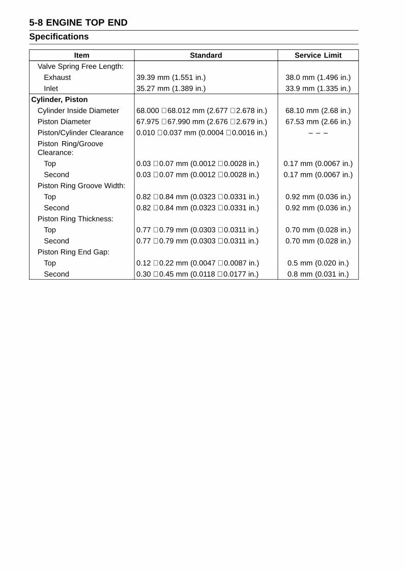
5-8 ENGINE TOP ENDSpecifications
Item Standard Service LimitValve Spring Free Length:
Exhaust 39.39 mm (1.551 in.) 38.0 mm (1.496 in.)
Inlet 35.27 mm (1.389 in.) 33.9 mm (1.335 in.)
Cylinder, PistonCylinder Inside Diameter 68.000 ∼ 68.012 mm (2.677 ∼ 2.678 in.) 68.10 mm (2.68 in.)
Piston Diameter 67.975 ∼ 67.990 mm (2.676 ∼ 2.679 in.) 67.53 mm (2.66 in.)
Piston/Cylinder Clearance 0.010 ∼ 0.037 mm (0.0004 ∼ 0.0016 in.) – – –
Piston Ring/GrooveClearance:
Top 0.03 ∼ 0.07 mm (0.0012 ∼ 0.0028 in.) 0.17 mm (0.0067 in.)
Second 0.03 ∼ 0.07 mm (0.0012 ∼ 0.0028 in.) 0.17 mm (0.0067 in.)
Piston Ring Groove Width:
Top 0.82 ∼ 0.84 mm (0.0323 ∼ 0.0331 in.) 0.92 mm (0.036 in.)
Second 0.82 ∼ 0.84 mm (0.0323 ∼ 0.0331 in.) 0.92 mm (0.036 in.)
Piston Ring Thickness:
Top 0.77 ∼ 0.79 mm (0.0303 ∼ 0.0311 in.) 0.70 mm (0.028 in.)
Second 0.77 ∼ 0.79 mm (0.0303 ∼ 0.0311 in.) 0.70 mm (0.028 in.)
Piston Ring End Gap:
Top 0.12 ∼ 0.22 mm (0.0047 ∼ 0.0087 in.) 0.5 mm (0.020 in.)
Second 0.30 ∼ 0.45 mm (0.0118 ∼ 0.0177 in.) 0.8 mm (0.031 in.)

ENGINE TOP END 5-9Special Tools and Sealant
Compression Gauge, 20 kgf/cm²:57001-221
Valve Spring Compressor Assembly:57001-241
Piston Pin Puller Assembly:57001-910
Valve Seat Cutter, 45° - 24.5:57001-1113
Valve Seat Cutter, 45° - 27.5:57001-1114
Valve Seat Cutter, 32° - 25:57001-1118
Valve Seat Cutter, 32° - 28:57001-1119
Valve Seat Cutter Holder Bar:57001-1128
Valve Spring Compressor Adapter, 21:57001-1272
Valve Guide Arbor, 4:57001-1273
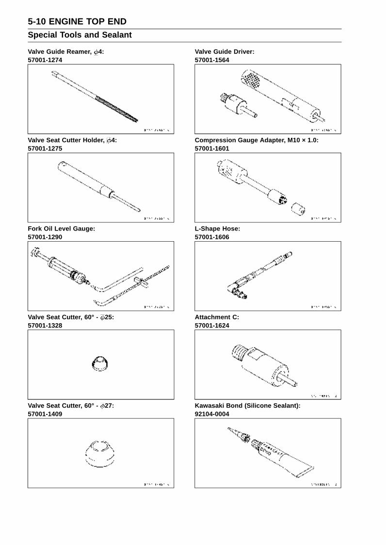
5-10 ENGINE TOP ENDSpecial Tools and Sealant
Valve Guide Reamer, 4:57001-1274
Valve Seat Cutter Holder, 4:57001-1275
Fork Oil Level Gauge:57001-1290
Valve Seat Cutter, 60° - 25:57001-1328
Valve Seat Cutter, 60° - 27:57001-1409
Valve Guide Driver:57001-1564
Compression Gauge Adapter, M10 × 1.0:57001-1601
L-Shape Hose:57001-1606
Attachment C:57001-1624
Kawasaki Bond (Silicone Sealant):92104-0004
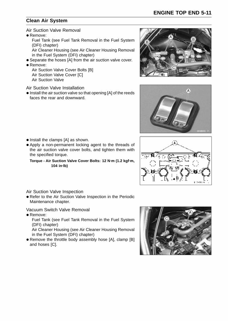
ENGINE TOP END 5-11Clean Air System
Air Suction Valve Removal•Remove:
Fuel Tank (see Fuel Tank Removal in the Fuel System(DFI) chapter)Air Cleaner Housing (see Air Cleaner Housing Removalin the Fuel System (DFI) chapter)
• Separate the hoses [A] from the air suction valve cover.
•Remove:Air Suction Valve Cover Bolts [B]Air Suction Valve Cover [C]Air Suction Valve
Air Suction Valve Installation• Install the air suction valve so that opening [A] of the reeds
faces the rear and downward.
• Install the clamps [A] as shown.
• Apply a non-permanent locking agent to the threads ofthe air suction valve cover bolts, and tighten them withthe specified torque.Torque - Air Suction Valve Cover Bolts: 12 N·m (1.2 kgf·m,
104 in·lb)
Air Suction Valve Inspection•Refer to the Air Suction Valve Inspection in the Periodic
Maintenance chapter.
Vacuum Switch Valve Removal•Remove:
Fuel Tank (see Fuel Tank Removal in the Fuel System(DFI) chapter)Air Cleaner Housing (see Air Cleaner Housing Removalin the Fuel System (DFI) chapter)
•Remove the throttle body assembly hose [A], clamp [B]and hoses [C].
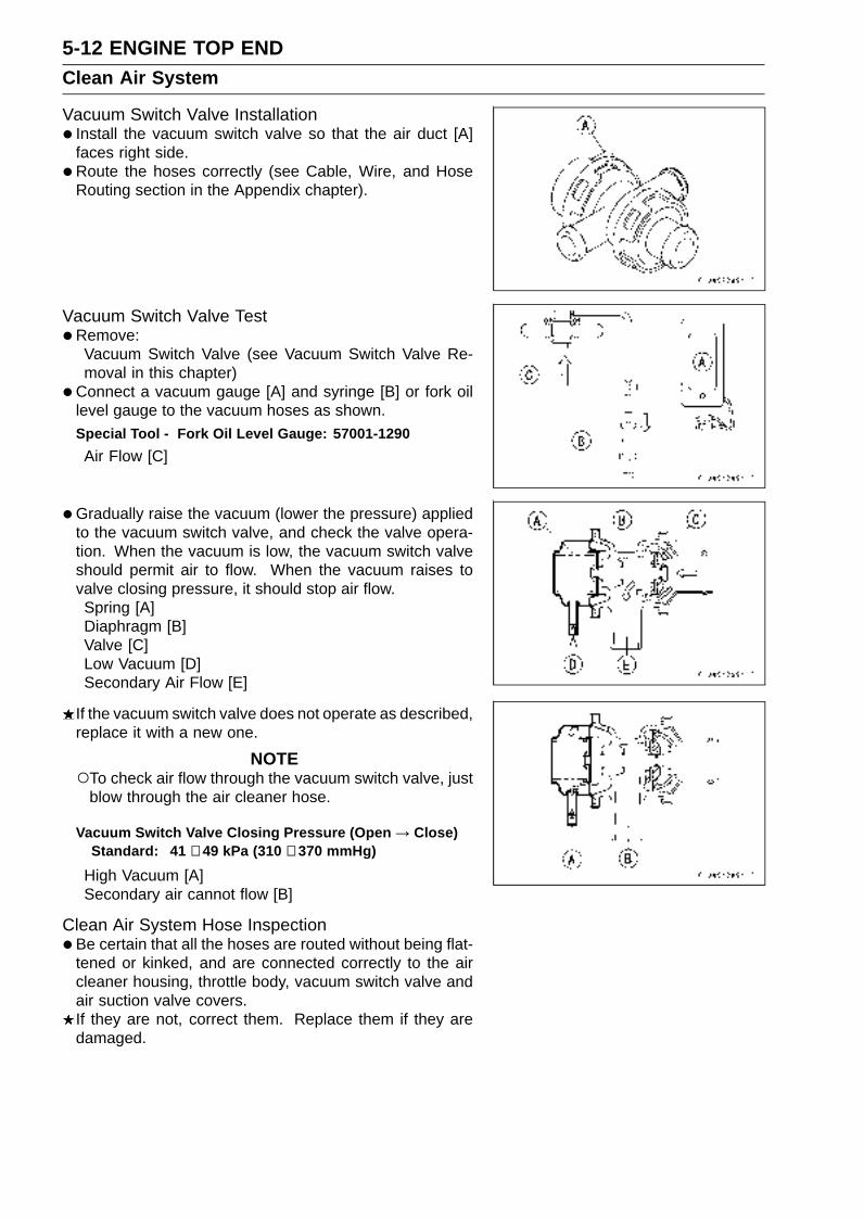
5-12 ENGINE TOP ENDClean Air System
Vacuum Switch Valve Installation• Install the vacuum switch valve so that the air duct [A]
faces right side.
•Route the hoses correctly (see Cable, Wire, and HoseRouting section in the Appendix chapter).
Vacuum Switch Valve Test•Remove:
Vacuum Switch Valve (see Vacuum Switch Valve Re-moval in this chapter)
•Connect a vacuum gauge [A] and syringe [B] or fork oillevel gauge to the vacuum hoses as shown.Special Tool - Fork Oil Level Gauge: 57001-1290
Air Flow [C]
•Gradually raise the vacuum (lower the pressure) appliedto the vacuum switch valve, and check the valve opera-tion. When the vacuum is low, the vacuum switch valveshould permit air to flow. When the vacuum raises tovalve closing pressure, it should stop air flow.Spring [A]Diaphragm [B]Valve [C]Low Vacuum [D]Secondary Air Flow [E]
If the vacuum switch valve does not operate as described,replace it with a new one.
NOTETo check air flow through the vacuum switch valve, just
blow through the air cleaner hose.
Vacuum Switch Valve Closing Pressure (Open → Close)Standard: 41 ∼ 49 kPa (310 ∼ 370 mmHg)
High Vacuum [A]Secondary air cannot flow [B]
Clean Air System Hose Inspection•Be certain that all the hoses are routed without being flat-
tened or kinked, and are connected correctly to the aircleaner housing, throttle body, vacuum switch valve andair suction valve covers.If they are not, correct them. Replace them if they aredamaged.

ENGINE TOP END 5-13Cylinder Head Cover
Cylinder Head Cover Removal•Remove:
Fuel Tank (see Fuel Tank Removal in the Fuel System(DFI) chapter)Air Cleaner Housing (see Air Cleaner Housing Removalin the Fuel System (DFI) chapter)Throttle Body Assembly (see Throttle Body AssemblyRemoval in the Fuel System (DFI) chapter)Vacuum Switch Valve [A] (see Vacuum Switch Valve Re-moval in this chapter)
• Free the heat insulation rubber plate.
•Remove:Air Suction Valve Covers (see Air Suction Valve Re-moval in this chapter)Stick Coils [A] (see Stick Coil (Ignition Coil together withSpark Plug Cap) Removal in the Electrical System chap-ter)
•Remove the cylinder head cover bolts [A].
• Remove the ground lead [B].
• Remove the cylinder head cover [A] to backward floatingit a little up.
Cylinder Head Cover Installation•Replace the head cover gasket with a new one.
• Apply silicone sealant [A] to the cylinder head as shown.Sealant - Kawasaki Bond (Silicone Sealant): 92104-0004

5-14 ENGINE TOP ENDCylinder Head Cover
• Install:Dowel Pins [A]Plug Hole Gaskets [B]
• Install the washer [A] with the metal side faces upward.
• Install the cylinder head cover.
• Tighten the cover bolts [A].Torque - Cylinder Head Cover Bolts: 9.8 N·m (1.0 kgf·m, 87
in·lb)
• Install the removed parts (see appropriate chapters).
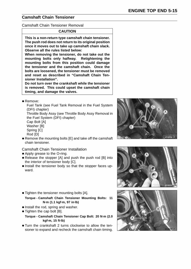
ENGINE TOP END 5-15Camshaft Chain Tensioner
Camshaft Chain Tensioner Removal
CAUTION
This is a non-return type camshaft chain tensioner.The push rod does not return to its original positiononce it moves out to take up camshaft chain slack.Observe all the rules listed below:When removing the tensioner, do not take out themounting bolts only halfway. Retightening themounting bolts from this position could damagethe tensioner and the camshaft chain. Once thebolts are loosened, the tensioner must be removedand reset as described in “Camshaft Chain Ten-sioner Installation”.Do not turn over the crankshaft while the tensioneris removed. This could upset the camshaft chaintiming, and damage the valves.
•Remove:Fuel Tank (see Fuel Tank Removal in the Fuel System(DFI) chapter)Throttle Body Assy (see Throttle Body Assy Removal inthe Fuel System (DFI) chapter)Cap Bolt [A]Washer [B]Spring [C]Rod [D]
•Remove the mounting bolts [E] and take off the camshaftchain tensioner.
Camshaft Chain Tensioner Installation•Apply grease to the O-ring.
•Release the stopper [A] and push the push rod [B] intothe interior of tensioner body [C].
• Install the tensioner body so that the stopper faces up-ward.
• Tighten the tensioner mounting bolts [A].Torque - Camshaft Chain Tensioner Mounting Bolts: 11
N·m (1.1 kgf·m, 97 in·lb)
• Install the rod, spring and washer.
• Tighten the cap bolt [B].Torque - Camshaft Chain Tensioner Cap Bolt: 20 N·m (2.0
kgf·m, 15 ft·lb)
•Turn the crankshaft 2 turns clockwise to allow the ten-sioner to expand and recheck the camshaft chain timing.
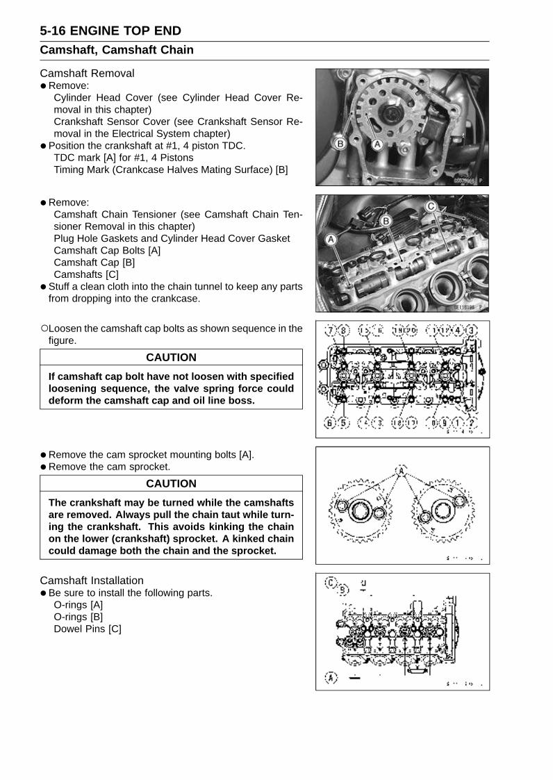
5-16 ENGINE TOP ENDCamshaft, Camshaft Chain
Camshaft Removal•Remove:
Cylinder Head Cover (see Cylinder Head Cover Re-moval in this chapter)Crankshaft Sensor Cover (see Crankshaft Sensor Re-moval in the Electrical System chapter)
• Position the crankshaft at #1, 4 piston TDC.TDC mark [A] for #1, 4 PistonsTiming Mark (Crankcase Halves Mating Surface) [B]
•Remove:Camshaft Chain Tensioner (see Camshaft Chain Ten-sioner Removal in this chapter)Plug Hole Gaskets and Cylinder Head Cover GasketCamshaft Cap Bolts [A]Camshaft Cap [B]Camshafts [C]
• Stuff a clean cloth into the chain tunnel to keep any partsfrom dropping into the crankcase.
Loosen the camshaft cap bolts as shown sequence in thefigure.
CAUTION
If camshaft cap bolt have not loosen with specifiedloosening sequence, the valve spring force coulddeform the camshaft cap and oil line boss.
•Remove the cam sprocket mounting bolts [A].
• Remove the cam sprocket.
CAUTION
The crankshaft may be turned while the camshaftsare removed. Always pull the chain taut while turn-ing the crankshaft. This avoids kinking the chainon the lower (crankshaft) sprocket. A kinked chaincould damage both the chain and the sprocket.
Camshaft Installation•Be sure to install the following parts.
O-rings [A]O-rings [B]Dowel Pins [C]

ENGINE TOP END 5-17Camshaft, Camshaft Chain
• Install the cam sprockets as shown in figure.#4 Cam Positions [A]Inlet Cam Sprocket [B]Exhaust Cam Sprocket [C]
• Apply a non-permanent locking agent to the threads andtighten the bolts.
Torque - Cam Sprocket Mounting Bolts: 15 N·m (1.5 kgf·m,11 ft·lb)
•Apply engine oil to all cam parts and journals.
• If a new camshaft is to be used, apply a thin coat of molyb-denum disulfide grease to the cam surfaces.
NOTEThe exhaust camshaft has a 161 EX mark [A] and the
inlet camshaft has a 161 IN mark [B]. Be careful not tomix up these shafts.
•Position the crankshaft at #1, 4 piston TDC.
•Pull the tension side (exhaust side) [A] of the chain tautto install the chain.
• Engage the camshaft chain with the camshaft sprocketsso that the timing marks on the sprockets are positionedas shown.The timing marks of #1, 4 must be aligned with the lower
surface of crankcase of rear side [B].The timing marks must be aligned with the cylinder head
upper surface [C].EX Mark [D]IN Mark [E]1st Pin [F]2nd Pin [G]3rd Pin [H]28th Pin [I]
• Install the camshaft cap.First tighten the camshaft cap bolts evenly to seat the
camshaft in place, then tighten all bolts following the spec-ified tightening sequence.First Round [1 ∼ 20]Second Round [1 ∼ 16]Final Tightening: [1 ∼ 20]
Torque - Camshaft Cap Bolts:
First, Second: 5.9 N·m (0.60 kgf·m, 52 in·lb)Final: 12 N·m (1.2 kgf·m, 104 in·lb)
• Install the camshaft chain tensioner (see Camshaft ChainTensioner Installation in this chapter).
• Install the removed parts (see appropriate chapters).

5-18 ENGINE TOP ENDCamshaft, Camshaft Chain
Camshaft, Camshaft Cap Wear•Remove:
Camshaft Cap (see Camshaft Removal in this chapter)
•Cut strips of plastigage to journal width. Place a stripon each journal parallel to the camshaft installed in thecorrect position.
•Measure each clearance between the camshaft journaland the camshaft cap using plastigage (press gauge) [A].
• Tighten:Torque - Camshaft Cap Bolts: 12 N·m (1.2 kgf·m, 104 in·lb)
NOTEDo not turn the camshaft when the plastigage is be-
tween the journal and camshaft cap.
Camshaft Journal, Camshaft Cap ClearanceStandard: 0.038 ∼ 0.081 mm (0.0015 ∼ 0.0032 in.)
Service Limit: 0.17 mm (0.0067 in.)
If any clearance exceeds the service limit, measure thediameter of each camshaft journal with a micrometer.
Camshaft Journal DiameterStandard: 23.940 ∼ 23.962 mm (0.9425 ∼ 0.9434 in.)
Service Limit: 23.91 mm (0.941 in.)
If the camshaft journal diameter is less than the servicelimit, replace the camshaft with a new one and measurethe clearance again.If the clearance still remains out of the limit, replace thecylinder head unit.
Camshaft Runout•Remove the camshaft (see Camshaft Removal in this
chapter).
• Set the camshaft in a camshaft alignment jig or on Vblocks.
•Measure runout with a dial gauge at the specified placeas shown.If the runout exceeds the service limit, replace the shaft.
Camshaft RunoutStandard: TIR 0.02 mm (0.0008 in.) or less
Service Limit: TIR 0.1 mm (0.004 in.)

ENGINE TOP END 5-19Camshaft, Camshaft Chain
Cam Wear•Remove the camshaft (see Camshaft Removal in this
chapter).
•Measure the height [A] of each cam with a micrometer.If the cams are worn down past the service limit, replacethe camshaft.
Cam HeightStandard:
Exhaust 33.146 ∼ 33.254 mm (1.3050 ∼ 1.3092 in.)
Inlet 34.146 ∼ 34.254 mm (1.3443 ∼ 1.3486 in.)
Service Limit:
Exhaust 33.05 mm (1.301 in.)
Inlet 34.05 mm (1.341 in.)
Camshaft Chain Removal•Split the crankcase (see Crankcase Splitting in the Crank-
shaft/Transmission chapter).
• Remove the camshaft chain [A] from the crankshaftsprocket.
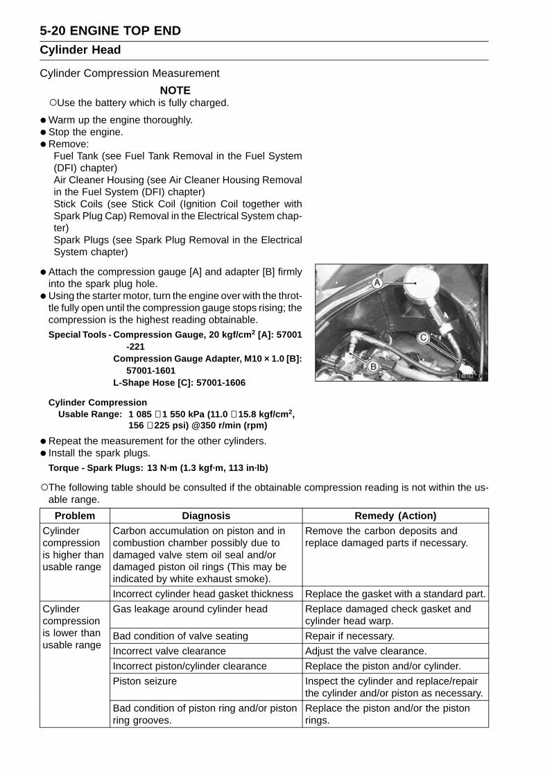
5-20 ENGINE TOP ENDCylinder Head
Cylinder Compression Measurement
NOTEUse the battery which is fully charged.
•Warm up the engine thoroughly.
• Stop the engine.
•Remove:Fuel Tank (see Fuel Tank Removal in the Fuel System(DFI) chapter)Air Cleaner Housing (see Air Cleaner Housing Removalin the Fuel System (DFI) chapter)Stick Coils (see Stick Coil (Ignition Coil together withSpark Plug Cap) Removal in the Electrical System chap-ter)Spark Plugs (see Spark Plug Removal in the ElectricalSystem chapter)
• Attach the compression gauge [A] and adapter [B] firmlyinto the spark plug hole.
•Using the starter motor, turn the engine over with the throt-tle fully open until the compression gauge stops rising; thecompression is the highest reading obtainable.Special Tools - Compression Gauge, 20 kgf/cm2 [A]: 57001
-221Compression Gauge Adapter, M10 × 1.0 [B]:
57001-1601L-Shape Hose [C]: 57001-1606
Cylinder CompressionUsable Range: 1 085 ∼ 1 550 kPa (11.0 ∼ 15.8 kgf/cm2,
156 ∼ 225 psi) @350 r/min (rpm)
•Repeat the measurement for the other cylinders.
• Install the spark plugs.Torque - Spark Plugs: 13 N·m (1.3 kgf·m, 113 in·lb)
The following table should be consulted if the obtainable compression reading is not within the us-able range.
Problem Diagnosis Remedy (Action)Carbon accumulation on piston and incombustion chamber possibly due todamaged valve stem oil seal and/ordamaged piston oil rings (This may beindicated by white exhaust smoke).
Remove the carbon deposits andreplace damaged parts if necessary.
Cylindercompressionis higher thanusable range
Incorrect cylinder head gasket thickness Replace the gasket with a standard part.
Gas leakage around cylinder head Replace damaged check gasket andcylinder head warp.
Bad condition of valve seating Repair if necessary.
Incorrect valve clearance Adjust the valve clearance.
Incorrect piston/cylinder clearance Replace the piston and/or cylinder.
Piston seizure Inspect the cylinder and replace/repairthe cylinder and/or piston as necessary.
Cylindercompressionis lower thanusable range
Bad condition of piston ring and/or pistonring grooves.
Replace the piston and/or the pistonrings.
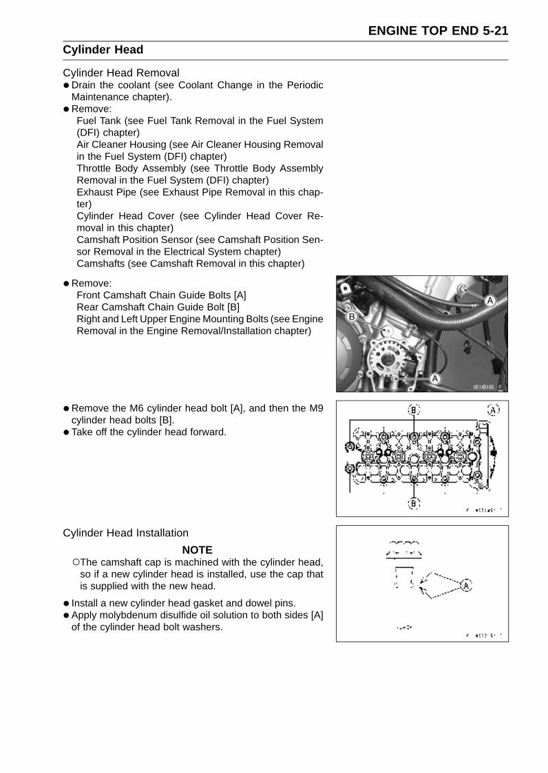
ENGINE TOP END 5-21Cylinder Head
Cylinder Head Removal•Drain the coolant (see Coolant Change in the Periodic
Maintenance chapter).
• Remove:Fuel Tank (see Fuel Tank Removal in the Fuel System(DFI) chapter)Air Cleaner Housing (see Air Cleaner Housing Removalin the Fuel System (DFI) chapter)Throttle Body Assembly (see Throttle Body AssemblyRemoval in the Fuel System (DFI) chapter)Exhaust Pipe (see Exhaust Pipe Removal in this chap-ter)Cylinder Head Cover (see Cylinder Head Cover Re-moval in this chapter)Camshaft Position Sensor (see Camshaft Position Sen-sor Removal in the Electrical System chapter)Camshafts (see Camshaft Removal in this chapter)
•Remove:Front Camshaft Chain Guide Bolts [A]Rear Camshaft Chain Guide Bolt [B]Right and Left Upper Engine Mounting Bolts (see EngineRemoval in the Engine Removal/Installation chapter)
•Remove the M6 cylinder head bolt [A], and then the M9cylinder head bolts [B].
• Take off the cylinder head forward.
Cylinder Head Installation
NOTEThe camshaft cap is machined with the cylinder head,
so if a new cylinder head is installed, use the cap thatis supplied with the new head.
• Install a new cylinder head gasket and dowel pins.
• Apply molybdenum disulfide oil solution to both sides [A]of the cylinder head bolt washers.

5-22 ENGINE TOP ENDCylinder Head
•Tighten the M9 cylinder head bolts following the tighteningsequence [1 ∼ 10].148 mm (5.83 in.)140 mm (5.51 in.)
Torque - Cylinder Head Bolts (M9):First: 20 N·m (2.0 kgf·m, 15 ft·lb)Final: 39 N·m (4.0 kgf·m, 29 ft·lb)
•Tighten the M6 cylinder head bolts [11].Torque - Cylinder Head Bolts (M6): 12 N·m (1.2 kgf·m, 104
in·lb)
• Install:Right and Left Upper Engine Mounting Bolts (see EngineInstallation in the Engine Removal/Installation chapter)Front Camshaft Chain Guide [A]Rear Camshaft Chain Guide [B]O-rings [C]Collar [D]Washer [E]
• Tighten:
Torque - Front Camshaft Chain Guide Bolt (Upper) [F]: 25N·m (2.5 kgf·m, 18 ft·lb)
Front Camshaft Chain Guide Bolt (Lower) [G]: 12N·m (1.2 kgf·m, 104 in·lb)
Rear Camshaft Chain Guide Bolt [H]: 25 N·m ( 2.5kgf·m, 18 ft·lb)
• Install the removed parts (see appropriate chapters).
Cylinder Head Warp•Clean the cylinder head.
• Lay a straightedge across the lower surface of the cylinderhead at several positions.
•Use a thickness gauge [A] to measure the space betweenthe straightedge [B] and the head.
Cylinder Head WarpStandard: – – –
Service Limit: 0.05 mm (0.002 in.)
If the cylinder head is warped more than the service limit,replace it.If the cylinder head is warped less than the service limit,repair the head by rubbing the lower surface on emerypaper secured to a surface plate (first No. 200, then No.400).

ENGINE TOP END 5-23Valves
Valve Clearance Inspection•Refer to the Valve Clearance Inspection in the Periodic
Maintenance chapter.
Valve Clearance Adjustment•Refer to the Valve Clearance Adjustment in the Periodic
Maintenance chapter.
Valve Removal•Remove the cylinder head (see Cylinder Head Removal
in this chapter).
• Remove the valve lifter and shim.Mark and record the valve lifter and shim locations so they
can be installed in their original positions.
•Using the valve spring compressor assembly, remove thevalve.
Special Tools - Valve Spring Compressor Assembly [A]:57001-241
Valve Spring Compressor Adapter, 21 [B]:57001-1272
Valve Installation•Replace the oil seal with a new one.
• Apply a thin coat of molybdenum disulfide grease to thevalve stem before valve installation.
• Install the springs so that the closed coil end faces down-wards.Valve Stem [A]Oil Seal [B]Spring Seat [C]Closed Coil End [D]Valve Spring [E]:
Exhaust-Yellow PaintInlet-Red Paint
Retainer [F]Split Keepers [G]
Valve Guide Removal•Remove:
Valve (see Valve Removal in this chapter)Oil SealSpring Seat
•Heat the area around the valve guide to 120 ∼ 150°C (248∼ 302°F), and hammer lightly on the valve guide arbor [A]to remove the guide from the top of the head.
CAUTION
Do not heat the cylinder head with a torch. This willwarp the cylinder head. Soak the cylinder head inoil and heat the oil.
Special Tool - Valve Guide Arbor, 4: 57001-1273
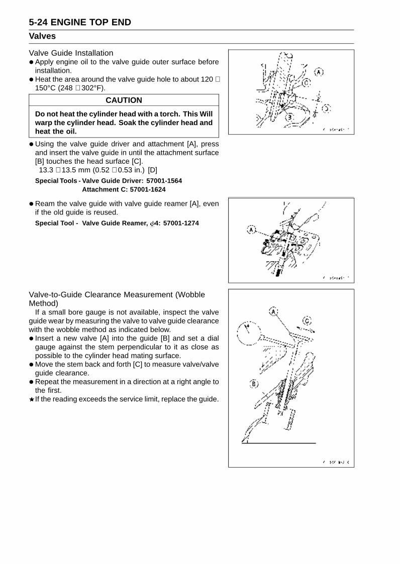
5-24 ENGINE TOP ENDValves
Valve Guide Installation•Apply engine oil to the valve guide outer surface before
installation.
•Heat the area around the valve guide hole to about 120 ∼150°C (248 ∼ 302°F).
CAUTION
Do not heat the cylinder head with a torch. This Willwarp the cylinder head. Soak the cylinder head andheat the oil.
•Using the valve guide driver and attachment [A], pressand insert the valve guide in until the attachment surface[B] touches the head surface [C].13.3 ∼ 13.5 mm (0.52 ∼ 0.53 in.) [D]
Special Tools - Valve Guide Driver: 57001-1564Attachment C: 57001-1624
•Ream the valve guide with valve guide reamer [A], evenif the old guide is reused.
Special Tool - Valve Guide Reamer, 4: 57001-1274
Valve-to-Guide Clearance Measurement (WobbleMethod)
If a small bore gauge is not available, inspect the valveguide wear by measuring the valve to valve guide clearancewith the wobble method as indicated below.
• Insert a new valve [A] into the guide [B] and set a dialgauge against the stem perpendicular to it as close aspossible to the cylinder head mating surface.
•Move the stem back and forth [C] to measure valve/valveguide clearance.
•Repeat the measurement in a direction at a right angle tothe first.If the reading exceeds the service limit, replace the guide.

ENGINE TOP END 5-25Valves
NOTEThe reading is not actual valve/valve guide clearance
because the measuring point is above the guide.
Valve/Valve Guide Clearance (Wobble Method)Standard:
Exhaust 0.09 ∼ 0.16 mm (0.0035 ∼ 0.0063 in.)
Inlet 0.03 ∼ 0.11 mm (0.0012 ∼ 0.0043 in.)
Service Limit:
Exhaust 0.40 mm (0.016 in.)
Inlet 0.35 mm (0.014 in.)
Valve Seat Inspection•Remove the valve (see Valve Removal in this chapter).
• Check the valve seating surface [A] between the valve [B]and valve seat [C].Measure the outside diameter [D] of the seating pattern
on the valve seat.If the outside diameter is too large or too small, repair theseat (see Valve Seat Repair in this chapter).
Valve Seating Surface Outside DiameterStandard:
Exhaust 23.5 ∼ 23.7 mm (0.925 ∼ 0.933 in.)
Inlet 27.9 ∼ 28.1 mm (1.098 ∼ 1.106 in.)
Measure the seat width [E] of the portion where there isno build-up carbon (white portion) of the valve seat with avernier caliper.Good [F]
If the width is too wide [G], too narrow [H] or uneven [J],repair the seat (see Valve Seat Repair in this chapter).
Valve Seating Surface WidthStandard:
Exhaust 0.6 ∼ 1.0 mm (0.024 ∼ 0.039 in.)
Inlet 0.8 ∼ 1.2 mm (0.031 ∼ 0.047 in.)
Valve Seat Repair•Repair the valve seat with the valve seat cutters [A].
Special Tools - Valve Seat Cutter Holder Bar [C]: 57001-1128
Valve Seat Cutter Holder, 4 [B]: 57001-1275
For Exhaust Valve Seat
Valve Seat Cutter, 45° - 27.5: 57001-1114Valve Seat Cutter, 32° - 28: 57001-1119Valve Seat Cutter, 60° - 27: 57001-1409
For Inlet Valve Seat
Valve Seat Cutter, 45° - 24.5: 57001-1113Valve Seat Cutter, 32° - 25: 57001-1118Valve Seat Cutter, 60° - 25: 57001-1328
If the manufacturer’s instructions are not available, usethe following procedure.

5-26 ENGINE TOP ENDValves
Seat Cutter Operation Care1. This valve seat cutter is developed to grind the valve for
repair. Therefore the cutter must not be used for otherpurposes than seat repair.
2. Do not drop or shock the valve seat cutter, or the dia-mond particles may fall off.
3. Do not fail to apply engine oil to the valve seat cutterbefore grinding the seat surface. Also wash off groundparticles sticking to the cutter with washing oil.
NOTEDo not use a wire brush to remove the metal particles
from the cutter. It will take off the diamond particles.
4. Setting the valve seat cutter holder in position, operatethe cutter in one hand. Do not apply too much force tothe diamond portion.
NOTEPrior to grinding, apply engine oil to the cutter and dur-
ing the operation, wash off any ground particles stickingto the cutter with washing oil.
5. After use, wash it with washing oil and apply thin layerof engine oil before storing.
Marks Stamped on the CutterThe marks stamped on the back of the cutter [A] represent
the following.60° ........................... Cutter angle [B]
37.5 ....................... Outer diameter of cutter [C]
Operating Procedures
•Clean the seat area carefully.
• Coat the seat with machinist’s dye.
• Fit a 45° cutter into the holder and slide it into the valveguide.
• Press down lightly on the handle and turn it right or left.Grind the seating surface only until it is smooth.
CAUTION
Do not grind the seat too much. Overgrinding willreduce valve clearance by sinking the valve into thehead. If the valve sinks too far into the head, it willbe impossible to adjust the clearance, and the cylin-der head must be replaced.
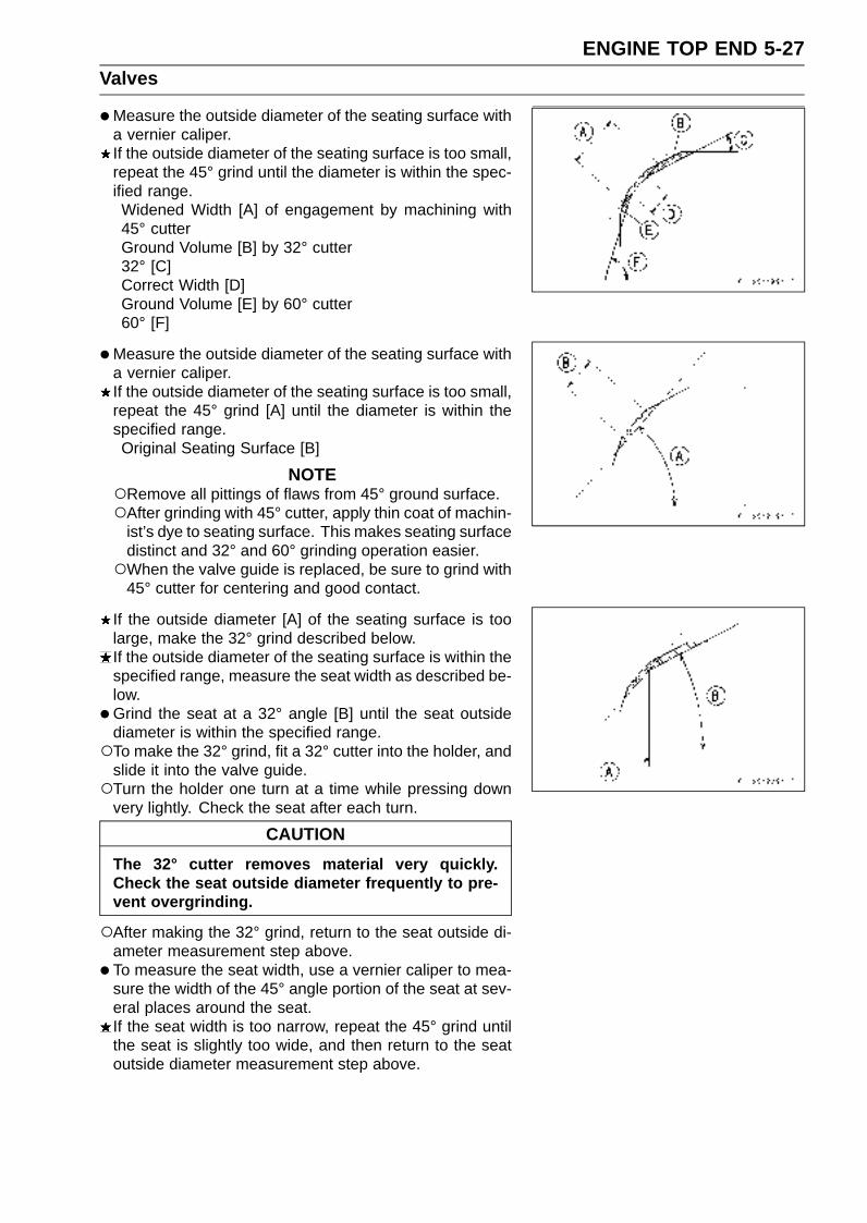
ENGINE TOP END 5-27Valves
•Measure the outside diameter of the seating surface witha vernier caliper.If the outside diameter of the seating surface is too small,repeat the 45° grind until the diameter is within the spec-ified range.Widened Width [A] of engagement by machining with45° cutterGround Volume [B] by 32° cutter32° [C]Correct Width [D]Ground Volume [E] by 60° cutter60° [F]
•Measure the outside diameter of the seating surface witha vernier caliper.If the outside diameter of the seating surface is too small,repeat the 45° grind [A] until the diameter is within thespecified range.Original Seating Surface [B]
NOTERemove all pittings of flaws from 45° ground surface.After grinding with 45° cutter, apply thin coat of machin-
ist’s dye to seating surface. This makes seating surfacedistinct and 32° and 60° grinding operation easier.When the valve guide is replaced, be sure to grind with
45° cutter for centering and good contact.
If the outside diameter [A] of the seating surface is toolarge, make the 32° grind described below.If the outside diameter of the seating surface is within thespecified range, measure the seat width as described be-low.
•Grind the seat at a 32° angle [B] until the seat outsidediameter is within the specified range.To make the 32° grind, fit a 32° cutter into the holder, and
slide it into the valve guide.Turn the holder one turn at a time while pressing down
very lightly. Check the seat after each turn.
CAUTION
The 32° cutter removes material very quickly.Check the seat outside diameter frequently to pre-vent overgrinding.
After making the 32° grind, return to the seat outside di-ameter measurement step above.
• To measure the seat width, use a vernier caliper to mea-sure the width of the 45° angle portion of the seat at sev-eral places around the seat.If the seat width is too narrow, repeat the 45° grind untilthe seat is slightly too wide, and then return to the seatoutside diameter measurement step above.
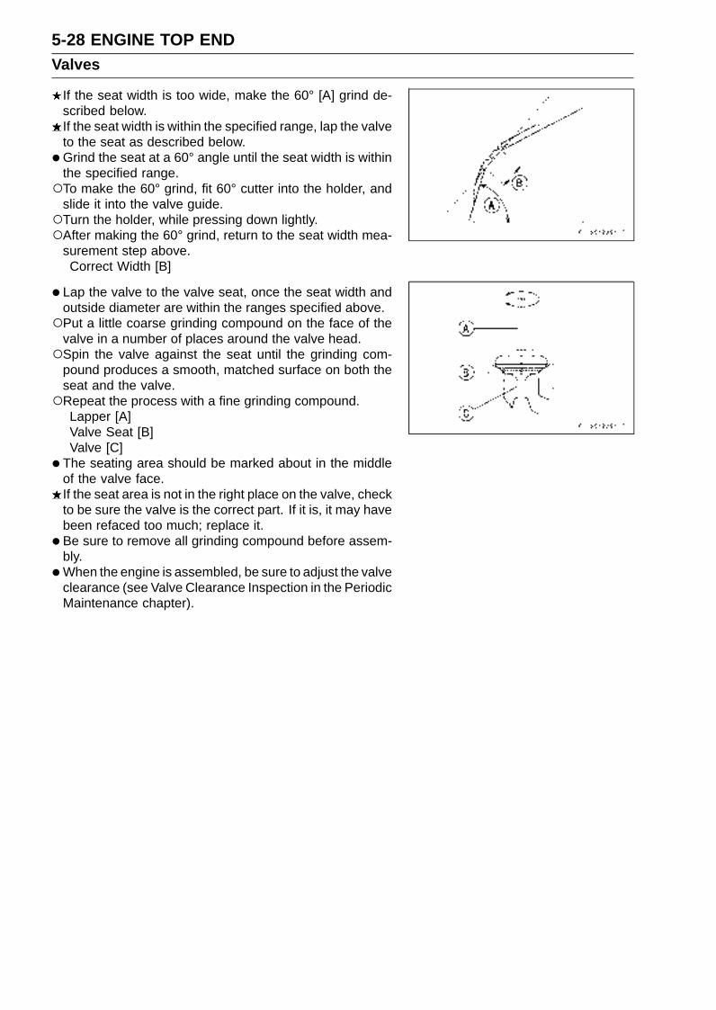
5-28 ENGINE TOP ENDValves
If the seat width is too wide, make the 60° [A] grind de-scribed below.If the seat width is within the specified range, lap the valveto the seat as described below.
•Grind the seat at a 60° angle until the seat width is withinthe specified range.To make the 60° grind, fit 60° cutter into the holder, and
slide it into the valve guide.Turn the holder, while pressing down lightly.After making the 60° grind, return to the seat width mea-
surement step above.Correct Width [B]
• Lap the valve to the valve seat, once the seat width andoutside diameter are within the ranges specified above.Put a little coarse grinding compound on the face of the
valve in a number of places around the valve head.Spin the valve against the seat until the grinding com-
pound produces a smooth, matched surface on both theseat and the valve.Repeat the process with a fine grinding compound.
Lapper [A]Valve Seat [B]Valve [C]
• The seating area should be marked about in the middleof the valve face.If the seat area is not in the right place on the valve, checkto be sure the valve is the correct part. If it is, it may havebeen refaced too much; replace it.
• Be sure to remove all grinding compound before assem-bly.
•When the engine is assembled, be sure to adjust the valveclearance (see Valve Clearance Inspection in the PeriodicMaintenance chapter).

ENGINE TOP END 5-29Valves
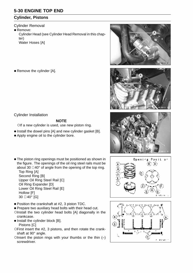
5-30 ENGINE TOP ENDCylinder, Pistons
Cylinder Removal•Remove:
Cylinder Head (see Cylinder Head Removal in this chap-ter)Water Hoses [A]
•Remove the cylinder [A].
Cylinder Installation
NOTEIf a new cylinder is used, use new piston ring.
• Install the dowel pins [A] and new cylinder gasket [B].
• Apply engine oil to the cylinder bore.
• The piston ring openings must be positioned as shown inthe figure. The openings of the oil ring steel rails must beabout 30 ∼ 40° of angle from the opening of the top ring.Top Ring [A]Second Ring [B]Upper Oil Ring Steel Rail [C]Oil Ring Expander [D]Lower Oil Ring Steel Rail [E]Hollow [F]30 ∼ 40° [G]
• Position the crankshaft at #2, 3 piston TDC.
•Prepare two auxiliary head bolts with their head cut.Install the two cylinder head bolts [A] diagonally in the
crankcase.
• Install the cylinder block [B].Pistons [C]
First insert the #2, 3 pistons, and then rotate the crank-shaft at 90° angle.Insert the piston rings with your thumbs or the thin (–)
screwdriver.

ENGINE TOP END 5-31Cylinder, Pistons
Piston Removal•Remove the cylinder (see Cylinder Removal in this chap-
ter).
• Place a clean cloth under the pistons and remove the pis-ton pin snap ring [A] from the outside of each piston.
•Remove the piston pins.
Special Tool - Piston Pin Puller Assembly [A]: 57001-910
•Remove the pistons.
•Carefully spread the ring opening with your thumbs andthen push up on the opposite side of the ring [A] to removeit.
• Remove the 3-piece oil ring with your thumbs in the samemanner.
Piston Installation• Install the oil ring expander [A] in the bottom piston ring
groove so the ends [B] not butt together.
• Install the oil ring steel rails, one above the expander andone below it.Spread the rail with your thumbs, but only enough to fit
the rail over the piston.Release the rail into the bottom piston ring groove.
NOTEThe oil ring steel rails have no “top” or “bottom”.
•Do not mix up the top and second ring.
• Install the top ring [A] so that the “R” mark [B] faces up.
• Install the second ring [C] so that the “RN” mark [D] facesup.Apply molybdenum disulfide oil solution to the piston
rings.
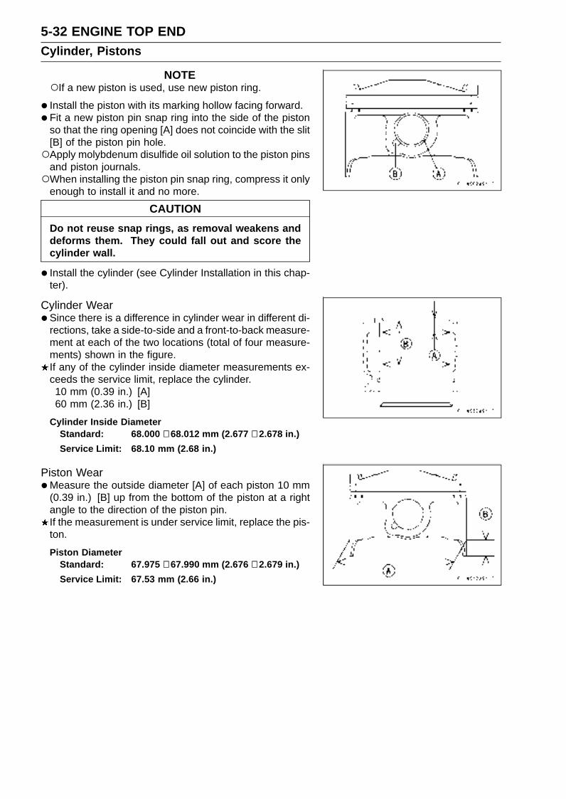
5-32 ENGINE TOP ENDCylinder, Pistons
NOTEIf a new piston is used, use new piston ring.
• Install the piston with its marking hollow facing forward.
• Fit a new piston pin snap ring into the side of the pistonso that the ring opening [A] does not coincide with the slit[B] of the piston pin hole.Apply molybdenum disulfide oil solution to the piston pins
and piston journals.When installing the piston pin snap ring, compress it only
enough to install it and no more.
CAUTION
Do not reuse snap rings, as removal weakens anddeforms them. They could fall out and score thecylinder wall.
• Install the cylinder (see Cylinder Installation in this chap-ter).
Cylinder Wear•Since there is a difference in cylinder wear in different di-
rections, take a side-to-side and a front-to-back measure-ment at each of the two locations (total of four measure-ments) shown in the figure.If any of the cylinder inside diameter measurements ex-ceeds the service limit, replace the cylinder.10 mm (0.39 in.) [A]60 mm (2.36 in.) [B]
Cylinder Inside DiameterStandard: 68.000 ∼ 68.012 mm (2.677 ∼ 2.678 in.)
Service Limit: 68.10 mm (2.68 in.)
Piston Wear•Measure the outside diameter [A] of each piston 10 mm
(0.39 in.) [B] up from the bottom of the piston at a rightangle to the direction of the piston pin.If the measurement is under service limit, replace the pis-ton.
Piston DiameterStandard: 67.975 ∼ 67.990 mm (2.676 ∼ 2.679 in.)
Service Limit: 67.53 mm (2.66 in.)

ENGINE TOP END 5-33Cylinder, Pistons
Piston Ring, Piston Ring Groove Wear•Check for uneven groove wear by inspecting the ring seat-
ing.The rings should fit perfectly parallel to groove surfaces.If not, replace the piston and all the piston rings.
•With the piston rings in their grooves, make several mea-surements with a thickness gauge [A] to determine pistonring/groove clearance.
Piston Ring/Groove ClearanceStandard:
Top 0.03 ∼ 0.07 mm (0.0012 ∼ 0.0028 in.)
Second 0.03 ∼ 0.07 mm (0.0012 ∼ 0.0028 in.)
Service Limit:
Top 0.17 mm (0.0067 in.)
Second 0.17 mm (0.0067 in.)
Piston Ring Groove Width•Measure the piston ring groove width.Use a vernier caliper at several points around the piston.
Piston Ring Groove WidthStandard:
Top [A] 0.82 ∼ 0.84 mm (0.0323 ∼ 0.0331 in.)
Second [B] 0.82 ∼ 0.84 mm (0.0323 ∼ 0.0331 in.)
Service Limit:
Top [A] 0.92 mm (0.036 in.)
Second [B] 0.92 mm (0.036 in.)
If the width of any of the two grooves is wider than theservice limit at any point, replace the piston.
Piston Ring Thickness•Measure the piston ring thickness.Use the micrometer to measure at several points around
the ring.
Piston Ring ThicknessStandard:
Top [A] 0.77 ∼ 0.79 mm (0.0303 ∼ 0.0311 in.)
Second [B] 0.77 ∼ 0.79 mm (0.0303 ∼ 0.0311 in.)
Service Limit:
Top [A] 0.70 mm (0.028 in.)
Second [B] 0.70 mm (0.028 in.)
If any of the measurements is less than the service limiton either of the rings, replace all the rings.
NOTEWhen using new rings in a used piston, check for un-
even groove wear. The rings should fit perfectly parallelto the groove sides. If not, replace the piston.
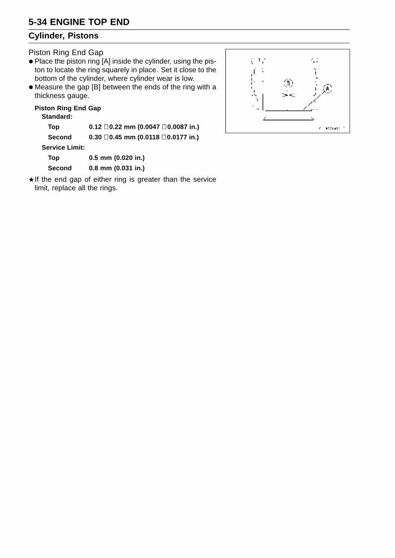
5-34 ENGINE TOP ENDCylinder, Pistons
Piston Ring End Gap•Place the piston ring [A] inside the cylinder, using the pis-
ton to locate the ring squarely in place. Set it close to thebottom of the cylinder, where cylinder wear is low.
•Measure the gap [B] between the ends of the ring with athickness gauge.
Piston Ring End GapStandard:
Top 0.12 ∼ 0.22 mm (0.0047 ∼ 0.0087 in.)
Second 0.30 ∼ 0.45 mm (0.0118 ∼ 0.0177 in.)
Service Limit:
Top 0.5 mm (0.020 in.)
Second 0.8 mm (0.031 in.)
If the end gap of either ring is greater than the servicelimit, replace all the rings.
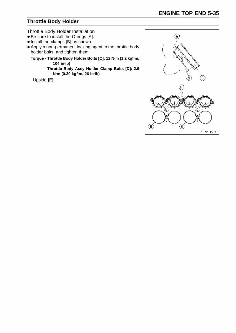
ENGINE TOP END 5-35Throttle Body Holder
Throttle Body Holder Installation•Be sure to install the O-rings [A].
• Install the clamps [B] as shown.
• Apply a non-permanent locking agent to the throttle bodyholder bolts, and tighten them.Torque - Throttle Body Holder Bolts [C]: 12 N·m (1.2 kgf·m,
104 in·lb)Throttle Body Assy Holder Clamp Bolts [D]: 2.9
N·m (0.30 kgf·m, 26 in·lb)
Upside [E]
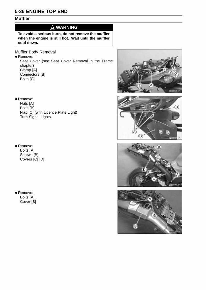
5-36 ENGINE TOP ENDMuffler
WARNINGTo avoid a serious burn, do not remove the mufflerwhen the engine is still hot. Wait until the mufflercool down.
Muffler Body Removal•Remove:
Seat Cover (see Seat Cover Removal in the Framechapter)Clamp [A]Connectors [B]Bolts [C]
•Remove:Nuts [A]Bolts [B]Flap [C] (with Licence Plate Light)Turn Signal Lights
•Remove:Bolts [A]Screws [B]Covers [C] [D]
•Remove:Bolts [A]Cover [B]
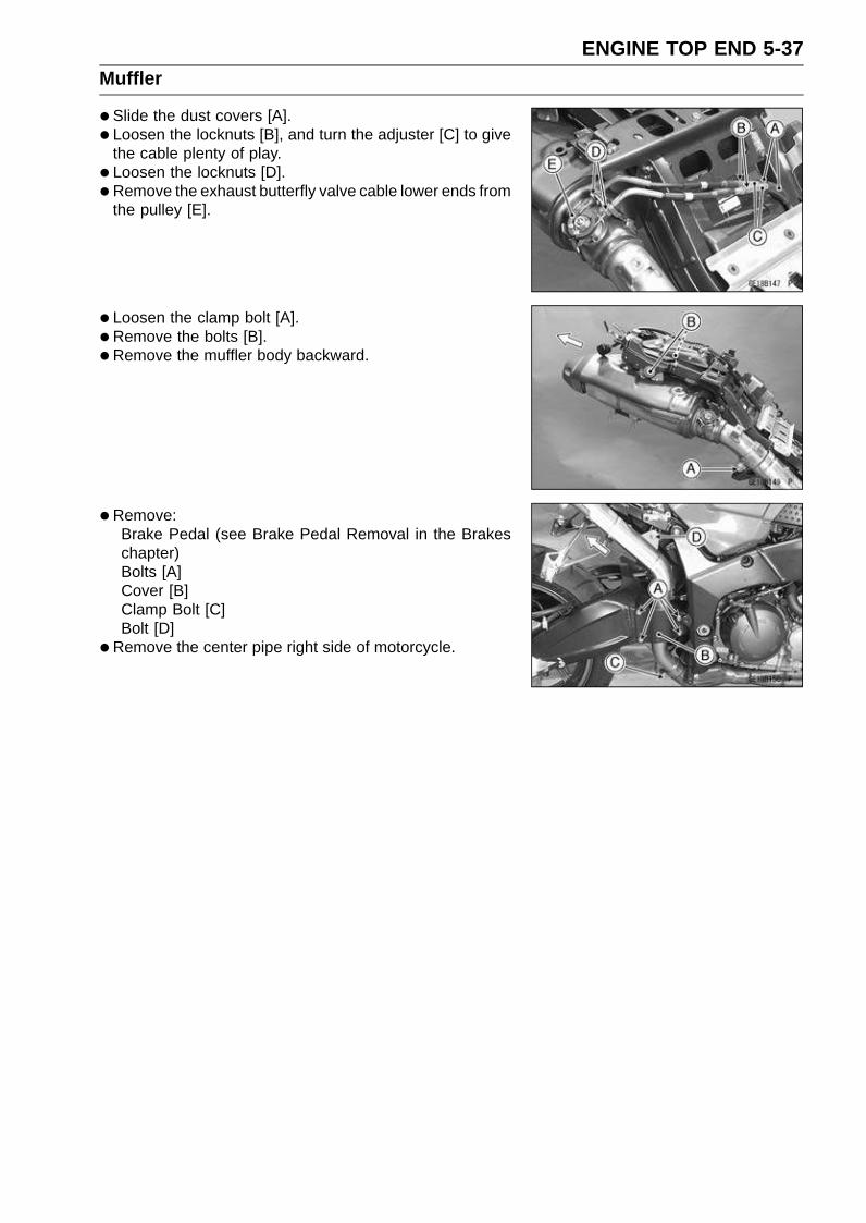
ENGINE TOP END 5-37Muffler
•Slide the dust covers [A].
• Loosen the locknuts [B], and turn the adjuster [C] to givethe cable plenty of play.
• Loosen the locknuts [D].
• Remove the exhaust butterfly valve cable lower ends fromthe pulley [E].
• Loosen the clamp bolt [A].
• Remove the bolts [B].
• Remove the muffler body backward.
•Remove:Brake Pedal (see Brake Pedal Removal in the Brakeschapter)Bolts [A]Cover [B]Clamp Bolt [C]Bolt [D]
•Remove the center pipe right side of motorcycle.

5-38 ENGINE TOP ENDMuffler
Muffler Body Installation•Replace the muffler body gasket [A] and center pipe gas-
ket [B] with a new one.Install the muffler body gasket and center pipe gasket until
it is bottomed so that the chamfer side faces rear.
• Install the center pipe [C].Install the center pipe until it stops at the bottom surface
of the exhaust pipe.
• Install the exhaust pipe clamp bolt [D] as shown.Upside [E]Outside [F]Rear View [G]About 6 mm (0.24 in.) [H]
• Install the muffler body.Install the muffler body until it stops at the bottom surface
of the center pipe.
• Install the muffler body clamp bolt as shown.Upside [E]Outside [F]Rear View [G]About 8 mm [I] (0.31 in.)
• Tighten:Torque - Exhaust Pipe Clamp Bolt: 17 N·m (1.7 kgf·m, 12
ft·lb)Exhaust Pipe Mounting Bolt [J]: 25 N·m (2.5 kgf·m,
18 ft·lb)Muffler Body Mounting Bolts [K]: 25 N·m (2.5
kgf·m, 18 ft·lb)Muffler Body Clamp Bolt [L]: 17 N·m (1.7 kgf·m, 12
ft·lb)
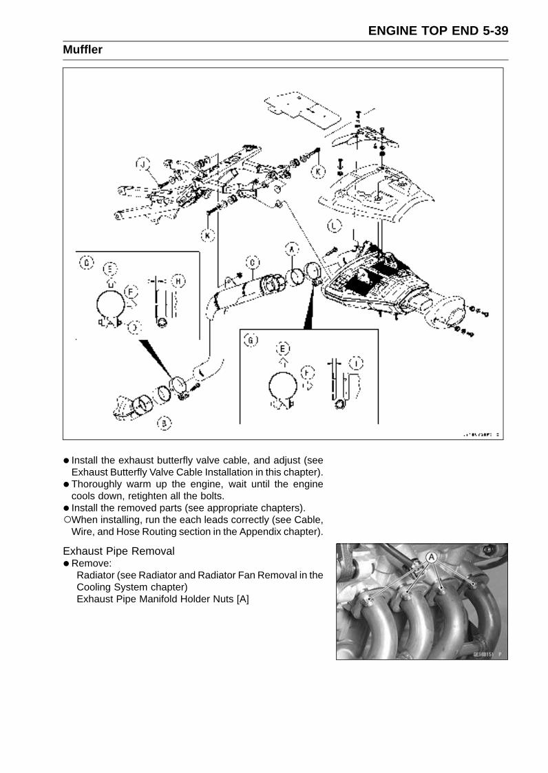
ENGINE TOP END 5-39Muffler
• Install the exhaust butterfly valve cable, and adjust (seeExhaust Butterfly Valve Cable Installation in this chapter).
• Thoroughly warm up the engine, wait until the enginecools down, retighten all the bolts.
• Install the removed parts (see appropriate chapters).When installing, run the each leads correctly (see Cable,
Wire, and Hose Routing section in the Appendix chapter).
Exhaust Pipe Removal•Remove:
Radiator (see Radiator and Radiator Fan Removal in theCooling System chapter)Exhaust Pipe Manifold Holder Nuts [A]

5-40 ENGINE TOP ENDMuffler
•Remove:Exhaust Pipe Clamp Bolt [A]
•Remove the exhaust pipe forward.
Exhaust Pipe Installation•Replace the exhaust pipe gaskets [A] and center pipe
gasket [B] with new ones and install them.Install the center pipe gasket until it is bottomed so that
the chamfer side faces rear.
• Install:Exhaust Pipe [C]
• Install the exhaust pipe clamp bolt [D] as shown.Upside [E]Outside [F]Rear View [G]About 6 mm (0.24 in.) [H]
• Tighten:Torque - Exhaust Pipe Clamp Bolt: 17 N·m (1.7 kgf·m, 12
ft·lb)Exhaust Pipe Manifold Holder Nuts [I]: 17 N·m (1.7
kgf·m, 12 ft·lb)
•Thoroughly warm up the engine, wait until the enginecools down, retighten all the bolts and nuts.

ENGINE TOP END 5-41Muffler
Exhaust Butterfly Valve Cable Removal•Remove:
Seat Cover (see Seat Cover Removal in the Framechapter)Guard Bracket [A] (see ECU Removal in the Fuel Sys-tem chapter)Cover (see Muffler Body Removal in this chapter)
• Slide the dust covers [B].
• Loosen the locknuts [C], and turn the adjuster [D] to givethe cable plenty of play.
•Remove the clamp [A].
• Remove the exhaust butterfly valve cable upper ends [B]from the pulley [C].
• Loosen the locknuts [A].
• Remove the exhaust butterfly valve cable lower ends [B]from the pulley [C].
• Remove the exhaust butterfly valve cable.
Exhaust Butterfly Valve Cable Installation•Confirm whether it is an angle shown in figure.
NOTECorrect the position electrically after confirming use is
discontinued, and there is no damage when differingfrom the angle of shown in the figure.
If the angle is wrong, adjust the pulley (see Exhaust But-terfly Valve Actuator Installation in the Fuel System (DFI)chapter).41.7° ±7° [A]
CAUTION
Do not correct it with the tool, forcibly.
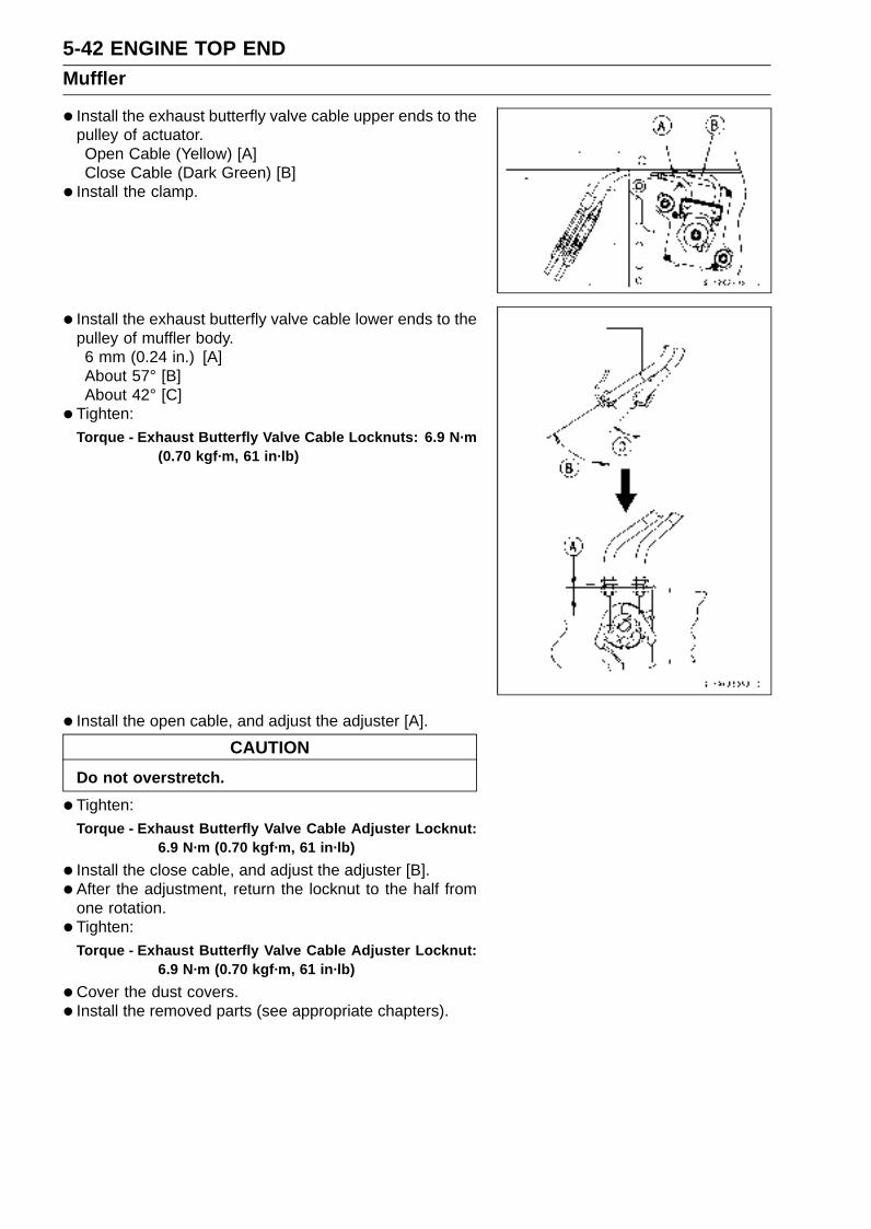
5-42 ENGINE TOP ENDMuffler
• Install the exhaust butterfly valve cable upper ends to thepulley of actuator.Open Cable (Yellow) [A]Close Cable (Dark Green) [B]
• Install the clamp.
• Install the exhaust butterfly valve cable lower ends to thepulley of muffler body.6 mm (0.24 in.) [A]About 57° [B]About 42° [C]
• Tighten:Torque - Exhaust Butterfly Valve Cable Locknuts: 6.9 N·m
(0.70 kgf·m, 61 in·lb)
• Install the open cable, and adjust the adjuster [A].
CAUTION
Do not overstretch.
•Tighten:Torque - Exhaust Butterfly Valve Cable Adjuster Locknut:
6.9 N·m (0.70 kgf·m, 61 in·lb)
• Install the close cable, and adjust the adjuster [B].
• After the adjustment, return the locknut to the half fromone rotation.
• Tighten:Torque - Exhaust Butterfly Valve Cable Adjuster Locknut:
6.9 N·m (0.70 kgf·m, 61 in·lb)
•Cover the dust covers.
• Install the removed parts (see appropriate chapters).

ENGINE TOP END 5-43Muffler


CLUTCH 6-1
6
Clutch
Table of Contents
Exploded View........................................................................................................................ 6-2Specifications ......................................................................................................................... 6-4Special Tool and Sealant ........................................................................................................ 6-5Clutch Lever and Cable .......................................................................................................... 6-6
Clutch Lever Free Play Inspection .................................................................................... 6-6Clutch Lever Free Play Adjustment .................................................................................. 6-6Cable Removal ................................................................................................................. 6-6Cable Installation .............................................................................................................. 6-6Cable Lubrication .............................................................................................................. 6-6Clutch Lever Installation.................................................................................................... 6-6
Clutch Cover........................................................................................................................... 6-7Clutch Cover Removal ...................................................................................................... 6-7Clutch Cover Installation ................................................................................................... 6-7Release Shaft Removal .................................................................................................... 6-7Release Shaft Installation ................................................................................................. 6-8Clutch Cover Disassembly................................................................................................ 6-8Clutch Cover Assembly..................................................................................................... 6-8
Clutch ..................................................................................................................................... 6-9Clutch Removal................................................................................................................. 6-9Clutch Installation.............................................................................................................. 6-10Spring Plate Free Play Measurement ............................................................................... 6-14Spring Plate Play Adjustment ........................................................................................... 6-15Clutch Plate, Wear, Damage Inspection ........................................................................... 6-15Clutch Plate Warp Inspection............................................................................................ 6-15Clutch Spring Free Length Measurement ......................................................................... 6-16Damper Cam Inspection ................................................................................................... 6-16
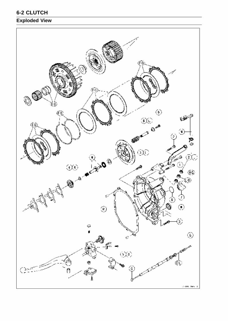
6-2 CLUTCHExploded View
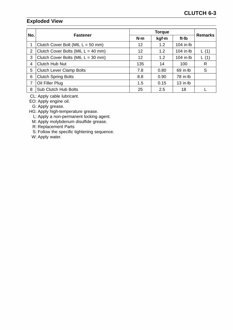
CLUTCH 6-3Exploded View
TorqueNo. Fastener
N·m kgf·m ft·lbRemarks
1 Clutch Cover Bolt (M6, L = 50 mm) 12 1.2 104 in·lb
2 Clutch Cover Bolts (M6, L = 40 mm) 12 1.2 104 in·lb L (1)
3 Clutch Cover Bolts (M6, L = 30 mm) 12 1.2 104 in·lb L (1)
4 Clutch Hub Nut 135 14 100 R
5 Clutch Lever Clamp Bolts 7.8 0.80 69 in·lb S
6 Clutch Spring Bolts 8.8 0.90 78 in·lb
7 Oil Filler Plug 1.5 0.15 13 in·lb
8 Sub Clutch Hub Bolts 25 2.5 18 L
CL: Apply cable lubricant.EO: Apply engine oil.
G: Apply grease.HG: Apply high-temperature grease.
L: Apply a non-permanent locking agent.M: Apply molybdenum disulfide grease.R: Replacement PartsS: Follow the specific tightening sequence.W: Apply water.

6-4 CLUTCHSpecifications
Item Standard Service LimitClutch Lever Free Play 2 ∼ 3 mm (0.08 ∼ 0.12 in.) – – –
ClutchSpring Plate Free Play (Usable Range)
0.05 ∼ 0.55 mm (0.002 ∼ 0.022 in.) – – –
Clutch Plate Assembly Length 39.1 mm (1.54 in.) – – –
Friction Plate Thickness 2.72 ∼ 2.88 mm (0.107 ∼ 0.113 in.) 2.6 mm (0.102 in.)
Friction and Steel Plate Warp 0.15 mm (0.006 in.) or less 0.3 mm (0.012 in.)
Clutch Spring Free Length 41.6 mm (1.64 in.) 40.1 mm (1.58 in.)
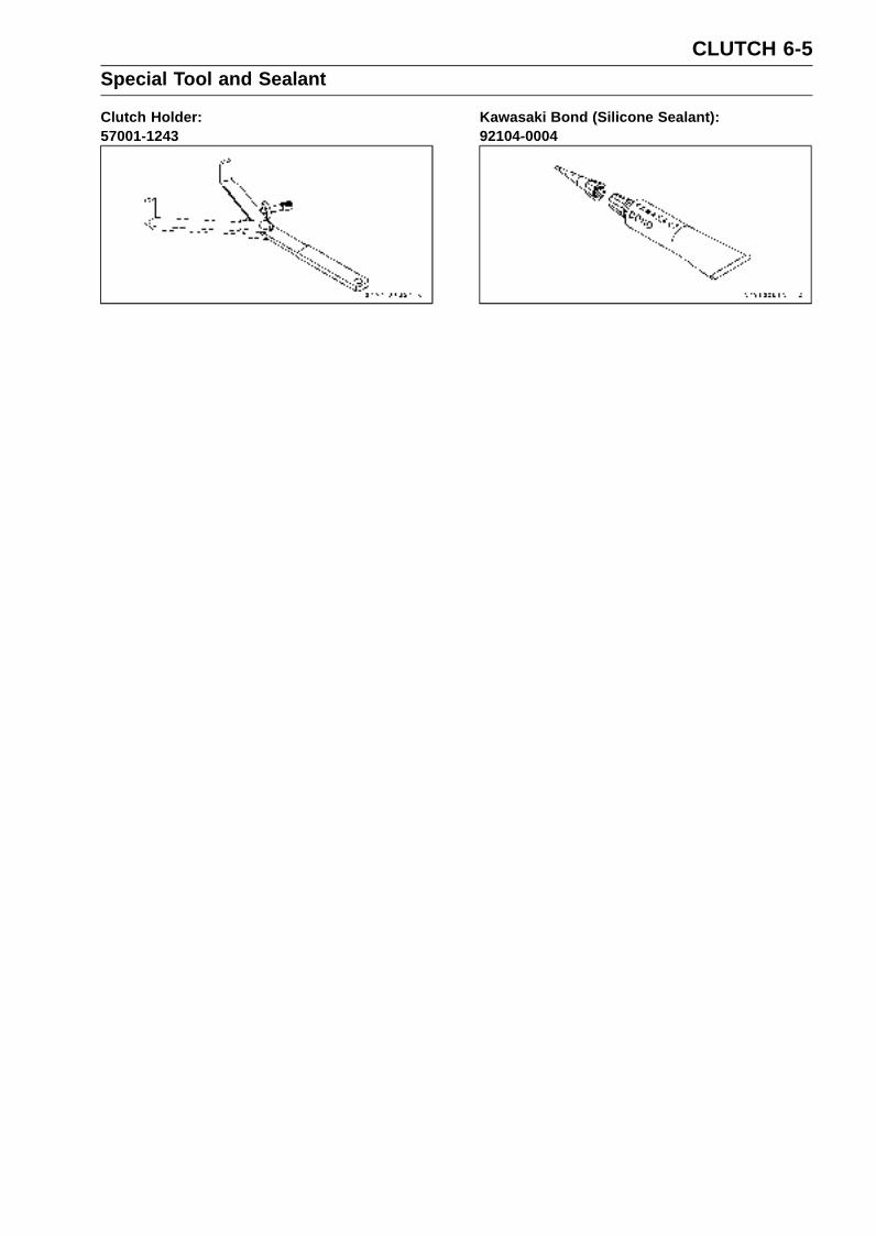
CLUTCH 6-5Special Tool and Sealant
Clutch Holder:57001-1243
Kawasaki Bond (Silicone Sealant):92104-0004
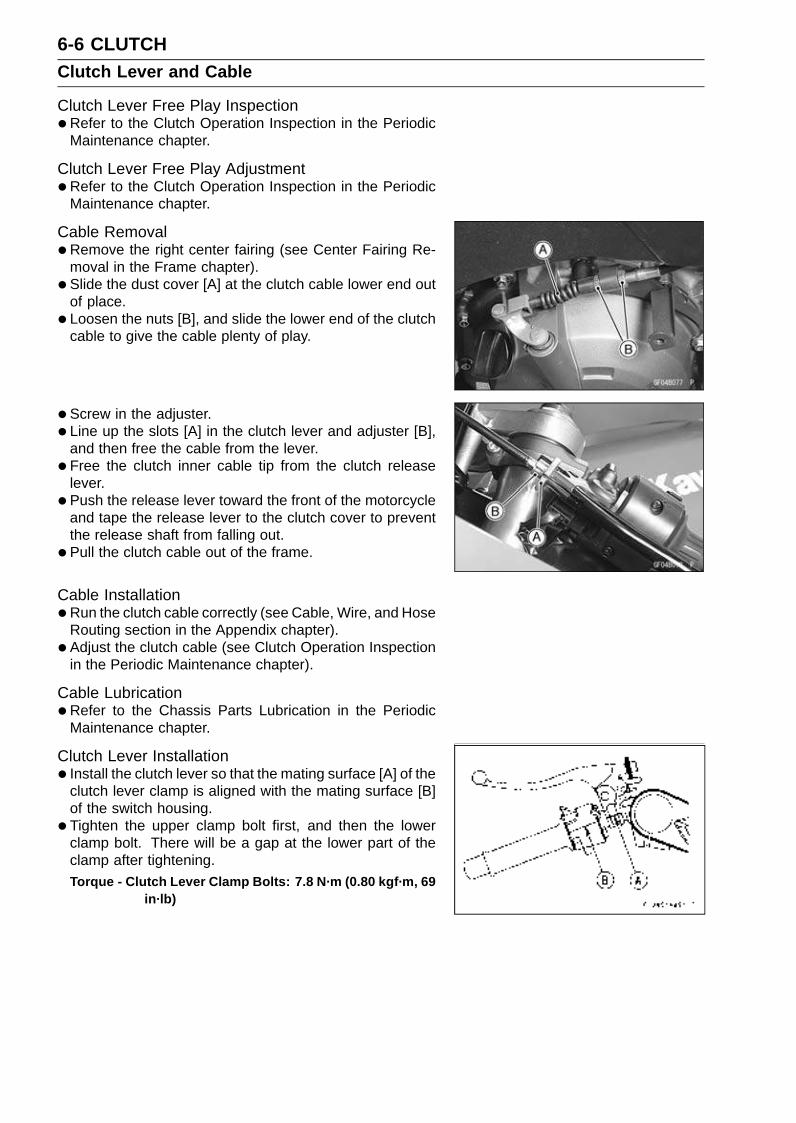
6-6 CLUTCHClutch Lever and Cable
Clutch Lever Free Play Inspection•Refer to the Clutch Operation Inspection in the Periodic
Maintenance chapter.
Clutch Lever Free Play Adjustment•Refer to the Clutch Operation Inspection in the Periodic
Maintenance chapter.
Cable Removal•Remove the right center fairing (see Center Fairing Re-
moval in the Frame chapter).
• Slide the dust cover [A] at the clutch cable lower end outof place.
• Loosen the nuts [B], and slide the lower end of the clutchcable to give the cable plenty of play.
• Screw in the adjuster.
• Line up the slots [A] in the clutch lever and adjuster [B],and then free the cable from the lever.
• Free the clutch inner cable tip from the clutch releaselever.
• Push the release lever toward the front of the motorcycleand tape the release lever to the clutch cover to preventthe release shaft from falling out.
• Pull the clutch cable out of the frame.
Cable Installation•Run the clutch cable correctly (see Cable, Wire, and Hose
Routing section in the Appendix chapter).
• Adjust the clutch cable (see Clutch Operation Inspectionin the Periodic Maintenance chapter).
Cable Lubrication•Refer to the Chassis Parts Lubrication in the Periodic
Maintenance chapter.
Clutch Lever Installation• Install the clutch lever so that the mating surface [A] of the
clutch lever clamp is aligned with the mating surface [B]of the switch housing.
• Tighten the upper clamp bolt first, and then the lowerclamp bolt. There will be a gap at the lower part of theclamp after tightening.Torque - Clutch Lever Clamp Bolts: 7.8 N·m (0.80 kgf·m, 69
in·lb)
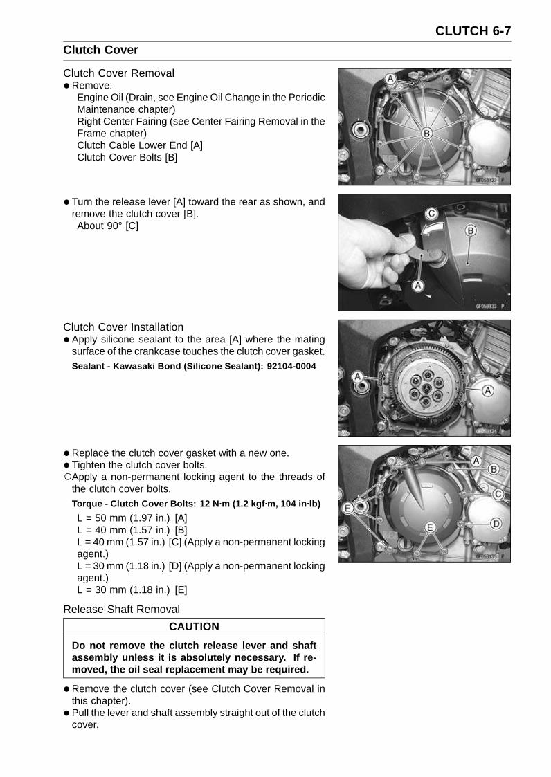
CLUTCH 6-7Clutch Cover
Clutch Cover Removal•Remove:
Engine Oil (Drain, see Engine Oil Change in the PeriodicMaintenance chapter)Right Center Fairing (see Center Fairing Removal in theFrame chapter)Clutch Cable Lower End [A]Clutch Cover Bolts [B]
• Turn the release lever [A] toward the rear as shown, andremove the clutch cover [B].About 90° [C]
Clutch Cover Installation•Apply silicone sealant to the area [A] where the mating
surface of the crankcase touches the clutch cover gasket.Sealant - Kawasaki Bond (Silicone Sealant): 92104-0004
•Replace the clutch cover gasket with a new one.
• Tighten the clutch cover bolts.Apply a non-permanent locking agent to the threads of
the clutch cover bolts.Torque - Clutch Cover Bolts: 12 N·m (1.2 kgf·m, 104 in·lb)
L = 50 mm (1.97 in.) [A]L = 40 mm (1.57 in.) [B]L = 40 mm (1.57 in.) [C] (Apply a non-permanent lockingagent.)L = 30 mm (1.18 in.) [D] (Apply a non-permanent lockingagent.)L = 30 mm (1.18 in.) [E]
Release Shaft Removal
CAUTION
Do not remove the clutch release lever and shaftassembly unless it is absolutely necessary. If re-moved, the oil seal replacement may be required.
•Remove the clutch cover (see Clutch Cover Removal inthis chapter).
• Pull the lever and shaft assembly straight out of the clutchcover.
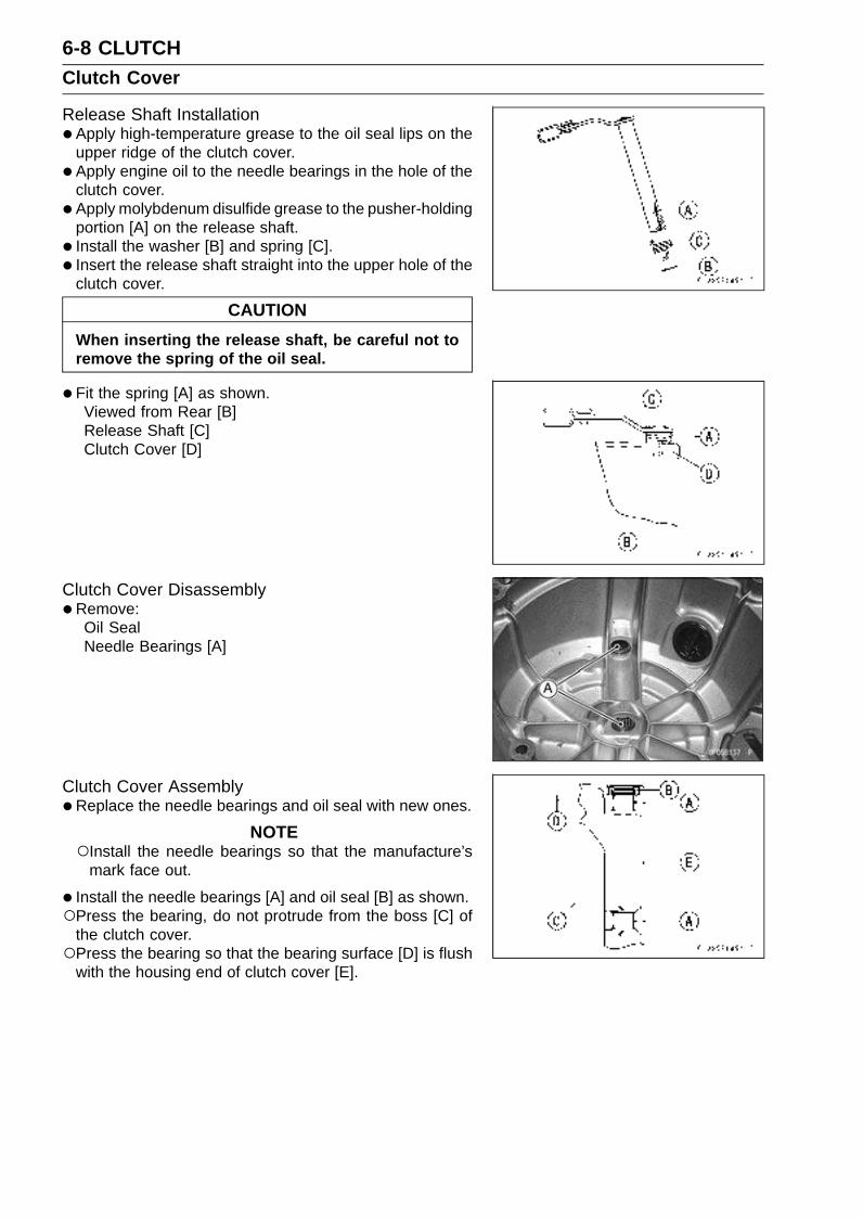
6-8 CLUTCHClutch Cover
Release Shaft Installation•Apply high-temperature grease to the oil seal lips on the
upper ridge of the clutch cover.
• Apply engine oil to the needle bearings in the hole of theclutch cover.
• Apply molybdenum disulfide grease to the pusher-holdingportion [A] on the release shaft.
• Install the washer [B] and spring [C].
• Insert the release shaft straight into the upper hole of theclutch cover.
CAUTION
When inserting the release shaft, be careful not toremove the spring of the oil seal.
•Fit the spring [A] as shown.Viewed from Rear [B]Release Shaft [C]Clutch Cover [D]
Clutch Cover Disassembly•Remove:
Oil SealNeedle Bearings [A]
Clutch Cover Assembly•Replace the needle bearings and oil seal with new ones.
NOTEInstall the needle bearings so that the manufacture’s
mark face out.
• Install the needle bearings [A] and oil seal [B] as shown.Press the bearing, do not protrude from the boss [C] of
the clutch cover.Press the bearing so that the bearing surface [D] is flush
with the housing end of clutch cover [E].

CLUTCH 6-9Clutch
Clutch Removal•Remove:
Engine Oil (Drain, see Engine Oil Change in the PeriodicMaintenance chapter)Right Center Fairing (see Center Fairing Removal in theFrame chapter)Clutch Cover (see Clutch Cover Removal in this chapter)Clutch Spring Bolts [A]Clutch SpringsClutch Spring Plate [B] (with shim, bearing, pusher [C],spring and washer)
•Remove:Friction Plates, Steel PlatesSpring, Spring SeatClutch Hub Nut [A]
Holding the sub clutch hub [B], remove the nut.
Special Tool - Clutch Holder [C]: 57001-1243
•Remove:Torque Limiter Springs [D]Sub Clutch HubClutch HubSpacer
•Using the two 4 mm (0.16 in.) screws [A], pull out thesleeve [B], needle bearing [C] and clutch housing [D].
• Remove the spacer.
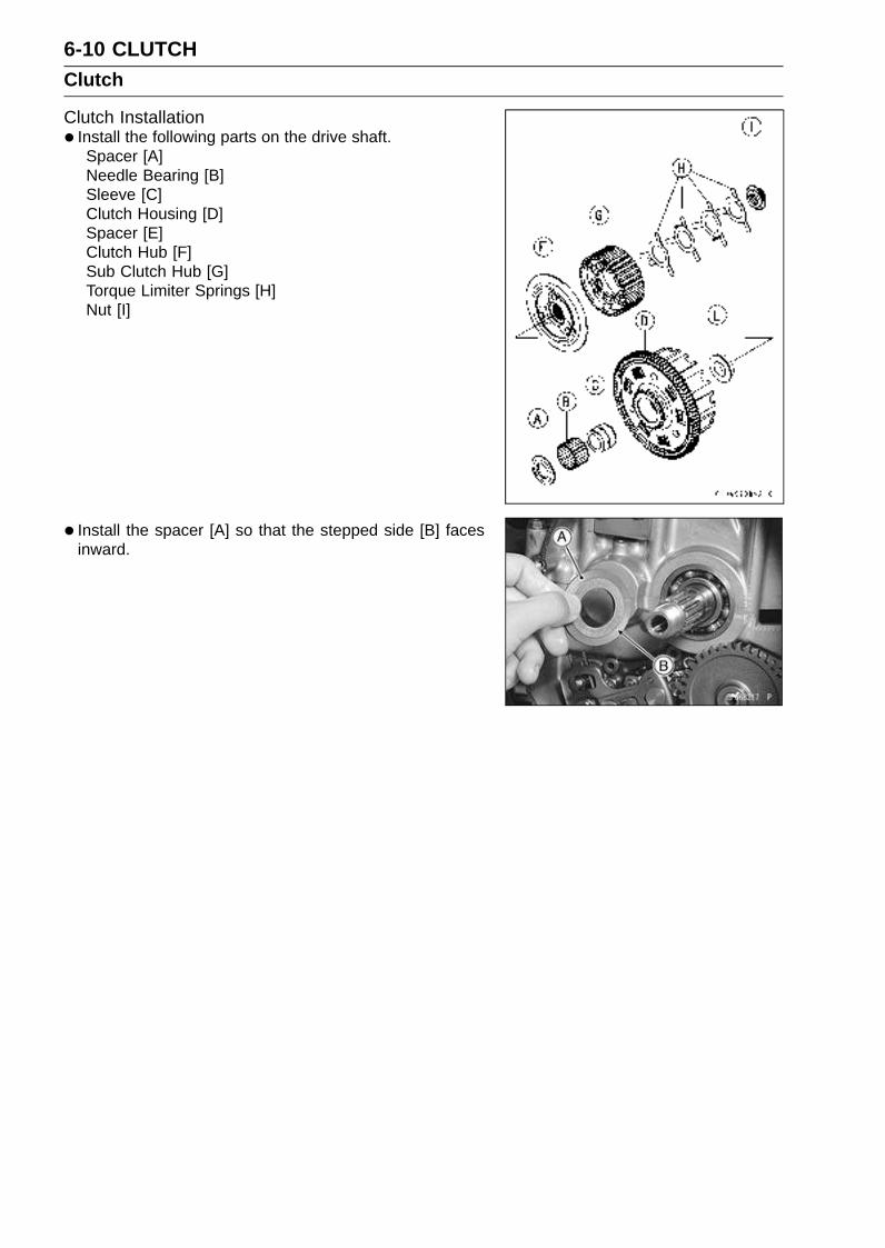
6-10 CLUTCHClutch
Clutch Installation• Install the following parts on the drive shaft.
Spacer [A]Needle Bearing [B]Sleeve [C]Clutch Housing [D]Spacer [E]Clutch Hub [F]Sub Clutch Hub [G]Torque Limiter Springs [H]Nut [I]
• Install the spacer [A] so that the stepped side [B] facesinward.

CLUTCH 6-11Clutch
• Install the clutch housing.If the clutch housing is replaced with a new one, select the
proper clutch housing in accordance with the combinationof the clutch housing gear and crankshaft markings.Clutch Housing Gear [A]Crankshaft [B]
NOTEBe sure to confirm the marking on the clutch housing
gear.
Clutch Housing Gear Selection when Replacing ClutchHousing Gear
Clutch HousingCrankshaftMarking [C] Gear Marking [D] Part Number
A A 13095-0044
None None 13095-0042
B B 13095-0045
C C 13095-0046
• Install the needle bearing and sleeve.
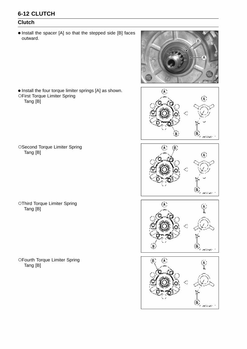
6-12 CLUTCHClutch
• Install the spacer [A] so that the stepped side [B] facesoutward.
• Install the four torque limiter springs [A] as shown.First Torque Limiter Spring
Tang [B]
Second Torque Limiter SpringTang [B]
Third Torque Limiter SpringTang [B]
Fourth Torque Limiter SpringTang [B]

CLUTCH 6-13Clutch
Replace the clutch hub nut with a new one.
•Holding the sub clutch hub, tighten the clutch hub nut.Special Tool - Clutch Holder: 57001-1243
Torque - Clutch Hub Nut: 135 N·m (14 kgf·m, 100 ft·lb)
• Install the friction plates and steel plates, starting with afriction plate and alternating them.
CAUTION
If new dry friction plates and steel plates are in-stalled, apply engine oil to the surfaces of eachplate to avoid clutch plate seizure.
Install the last friction plate [A] fitting the tangs in thegrooves in the housing as shown.
• Apply molybdenum disulfide grease to the pusher ends[A] and install the shim [B], bearing [C], pusher [D] in theclutch spring plate [E].Spring [F]Washer [G]
• Align the grooves [A] of the spring plate [B] to the grooves[C] of the sub clutch hub [D] to install the spring plate onthe sub clutch hub.
• Install the springs and spring holders, and tighten theclutch spring bolts.Torque - Clutch Spring Bolts: 8.8 N·m (0.90 kgf·m, 78 in·lb)
• Install the clutch cover (see Clutch Cover Installation inthis chapter).
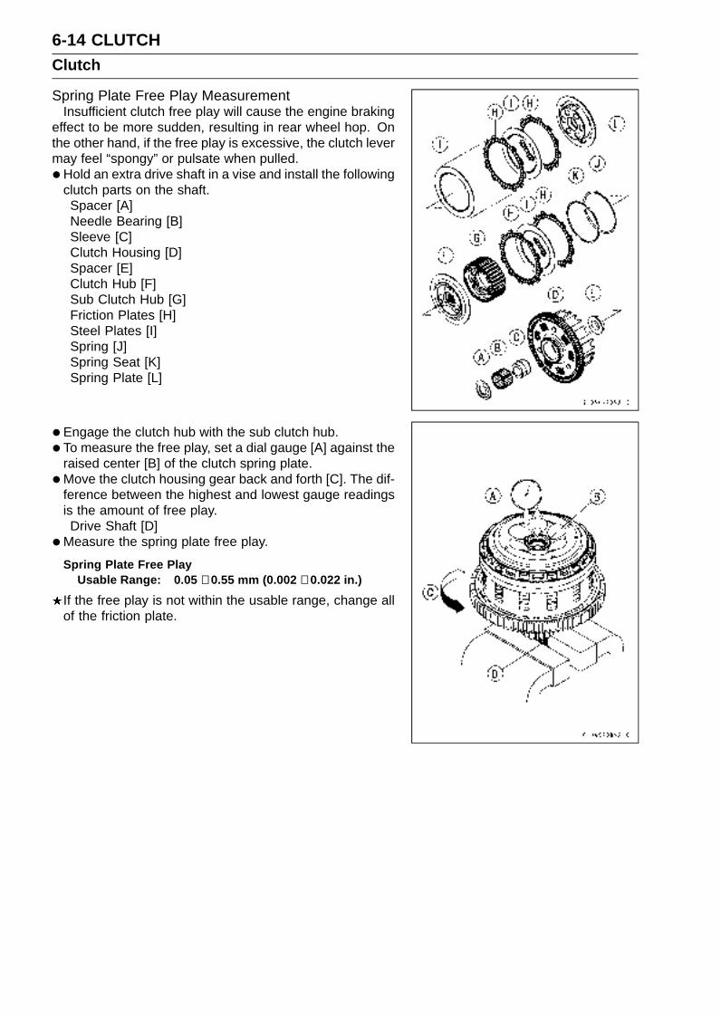
6-14 CLUTCHClutch
Spring Plate Free Play MeasurementInsufficient clutch free play will cause the engine braking
effect to be more sudden, resulting in rear wheel hop. Onthe other hand, if the free play is excessive, the clutch levermay feel “spongy” or pulsate when pulled.
•Hold an extra drive shaft in a vise and install the followingclutch parts on the shaft.Spacer [A]Needle Bearing [B]Sleeve [C]Clutch Housing [D]Spacer [E]Clutch Hub [F]Sub Clutch Hub [G]Friction Plates [H]Steel Plates [I]Spring [J]Spring Seat [K]Spring Plate [L]
• Engage the clutch hub with the sub clutch hub.
• To measure the free play, set a dial gauge [A] against theraised center [B] of the clutch spring plate.
•Move the clutch housing gear back and forth [C]. The dif-ference between the highest and lowest gauge readingsis the amount of free play.Drive Shaft [D]
•Measure the spring plate free play.
Spring Plate Free PlayUsable Range: 0.05 ∼ 0.55 mm (0.002 ∼ 0.022 in.)
If the free play is not within the usable range, change allof the friction plate.
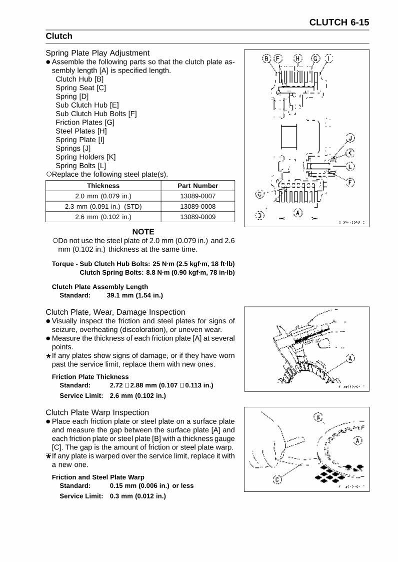
CLUTCH 6-15Clutch
Spring Plate Play Adjustment•Assemble the following parts so that the clutch plate as-
sembly length [A] is specified length.Clutch Hub [B]Spring Seat [C]Spring [D]Sub Clutch Hub [E]Sub Clutch Hub Bolts [F]Friction Plates [G]Steel Plates [H]Spring Plate [I]Springs [J]Spring Holders [K]Spring Bolts [L]
Replace the following steel plate(s).
Thickness Part Number
2.0 mm (0.079 in.) 13089-0007
2.3 mm (0.091 in.) (STD) 13089-0008
2.6 mm (0.102 in.) 13089-0009
NOTEDo not use the steel plate of 2.0 mm (0.079 in.) and 2.6
mm (0.102 in.) thickness at the same time.
Torque - Sub Clutch Hub Bolts: 25 N·m (2.5 kgf·m, 18 ft·lb)Clutch Spring Bolts: 8.8 N·m (0.90 kgf·m, 78 in·lb)
Clutch Plate Assembly LengthStandard: 39.1 mm (1.54 in.)
Clutch Plate, Wear, Damage Inspection•Visually inspect the friction and steel plates for signs of
seizure, overheating (discoloration), or uneven wear.
•Measure the thickness of each friction plate [A] at severalpoints.If any plates show signs of damage, or if they have wornpast the service limit, replace them with new ones.
Friction Plate ThicknessStandard: 2.72 ∼ 2.88 mm (0.107 ∼ 0.113 in.)
Service Limit: 2.6 mm (0.102 in.)
Clutch Plate Warp Inspection•Place each friction plate or steel plate on a surface plate
and measure the gap between the surface plate [A] andeach friction plate or steel plate [B] with a thickness gauge[C]. The gap is the amount of friction or steel plate warp.If any plate is warped over the service limit, replace it witha new one.
Friction and Steel Plate WarpStandard: 0.15 mm (0.006 in.) or less
Service Limit: 0.3 mm (0.012 in.)

6-16 CLUTCHClutch
Clutch Spring Free Length Measurement•Measure the free length of the clutch springs [A].
If any spring is shorter than the service limit, it must bereplaced.
Clutch Spring Free LengthStandard: 41.6 mm (1.64 in.)
Service Limit: 40.1 mm (1.58 in.)
Damper Cam Inspection•Remove the clutch (see Clutch Removal in this chapter).
• Visually inspect the damper cam [A], cam [B], and thetorque limiter spring [C].
• Replace the part if it appears damaged.

ENGINE LUBRICATION SYSTEM 7-1
7
Engine Lubrication System
Table of Contents
Exploded View........................................................................................................................ 7-2Specifications ......................................................................................................................... 7-4Special Tools and Sealant ...................................................................................................... 7-5Engine Oil Flow Chart............................................................................................................. 7-6Engine Oil and Oil Filter.......................................................................................................... 7-8
Oil Level Inspection........................................................................................................... 7-8Engine Oil Change............................................................................................................ 7-8Oil Filter Replacement ...................................................................................................... 7-8
Oil Pan.................................................................................................................................... 7-9Oil Pan Removal ............................................................................................................... 7-9Oil Pan Installation ............................................................................................................ 7-9
Oil Pressure Relief Valve........................................................................................................ 7-10Oil Pressure Relief Valve Removal ................................................................................... 7-10Oil Pressure Relief Valve Installation ................................................................................ 7-10Oil Pressure Relief Valve Inspection................................................................................. 7-10
Oil Pump................................................................................................................................. 7-11Oil Pump Removal ............................................................................................................ 7-11Oil Pump Installation ......................................................................................................... 7-11Oil Pump Drive Gear Removal.......................................................................................... 7-12Oil Pump Drive Gear Installation....................................................................................... 7-13
Oil Cooler................................................................................................................................ 7-14Oil Cooler Removal........................................................................................................... 7-14Oil Cooler Installation........................................................................................................ 7-14
Oil Pressure Measurement..................................................................................................... 7-15Oil Pressure Measurement ............................................................................................... 7-15
Oil Pressure Switch ................................................................................................................ 7-16Oil Pressure Switch Removal ........................................................................................... 7-16Oil Pressure Switch Installation ........................................................................................ 7-16
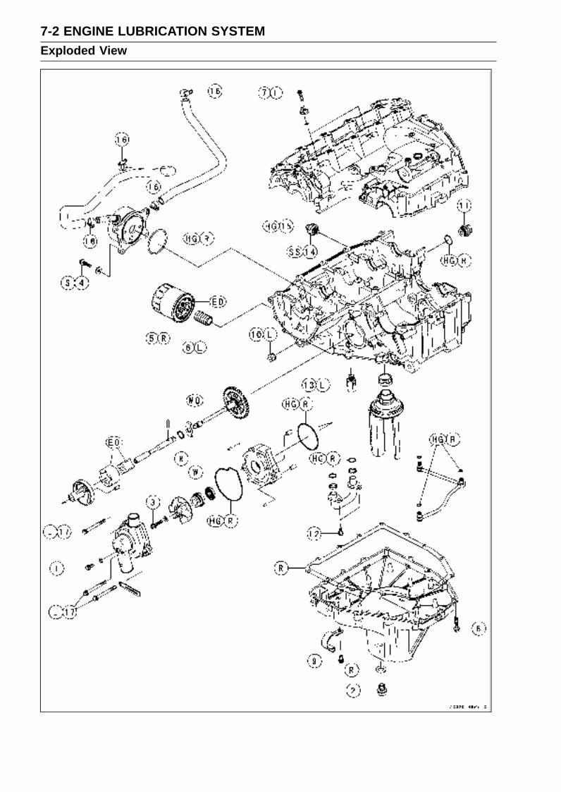
7-2 ENGINE LUBRICATION SYSTEMExploded View
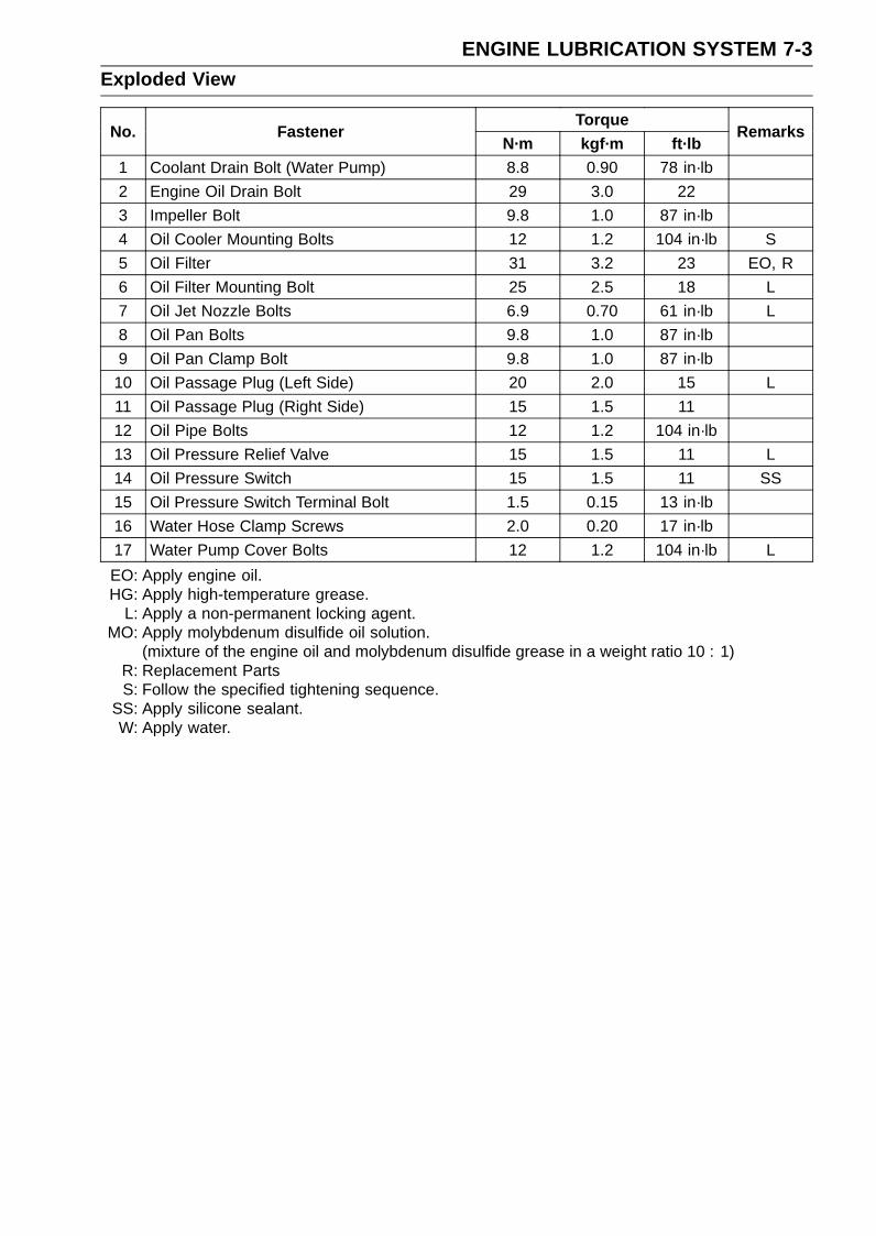
ENGINE LUBRICATION SYSTEM 7-3Exploded View
TorqueNo. Fastener
N·m kgf·m ft·lbRemarks
1 Coolant Drain Bolt (Water Pump) 8.8 0.90 78 in·lb
2 Engine Oil Drain Bolt 29 3.0 22
3 Impeller Bolt 9.8 1.0 87 in·lb
4 Oil Cooler Mounting Bolts 12 1.2 104 in·lb S
5 Oil Filter 31 3.2 23 EO, R
6 Oil Filter Mounting Bolt 25 2.5 18 L
7 Oil Jet Nozzle Bolts 6.9 0.70 61 in·lb L
8 Oil Pan Bolts 9.8 1.0 87 in·lb
9 Oil Pan Clamp Bolt 9.8 1.0 87 in·lb
10 Oil Passage Plug (Left Side) 20 2.0 15 L
11 Oil Passage Plug (Right Side) 15 1.5 11
12 Oil Pipe Bolts 12 1.2 104 in·lb
13 Oil Pressure Relief Valve 15 1.5 11 L
14 Oil Pressure Switch 15 1.5 11 SS
15 Oil Pressure Switch Terminal Bolt 1.5 0.15 13 in·lb
16 Water Hose Clamp Screws 2.0 0.20 17 in·lb
17 Water Pump Cover Bolts 12 1.2 104 in·lb L
EO: Apply engine oil.HG: Apply high-temperature grease.
L: Apply a non-permanent locking agent.MO: Apply molybdenum disulfide oil solution.
(mixture of the engine oil and molybdenum disulfide grease in a weight ratio 10 : 1)R: Replacement PartsS: Follow the specified tightening sequence.
SS: Apply silicone sealant.W: Apply water.
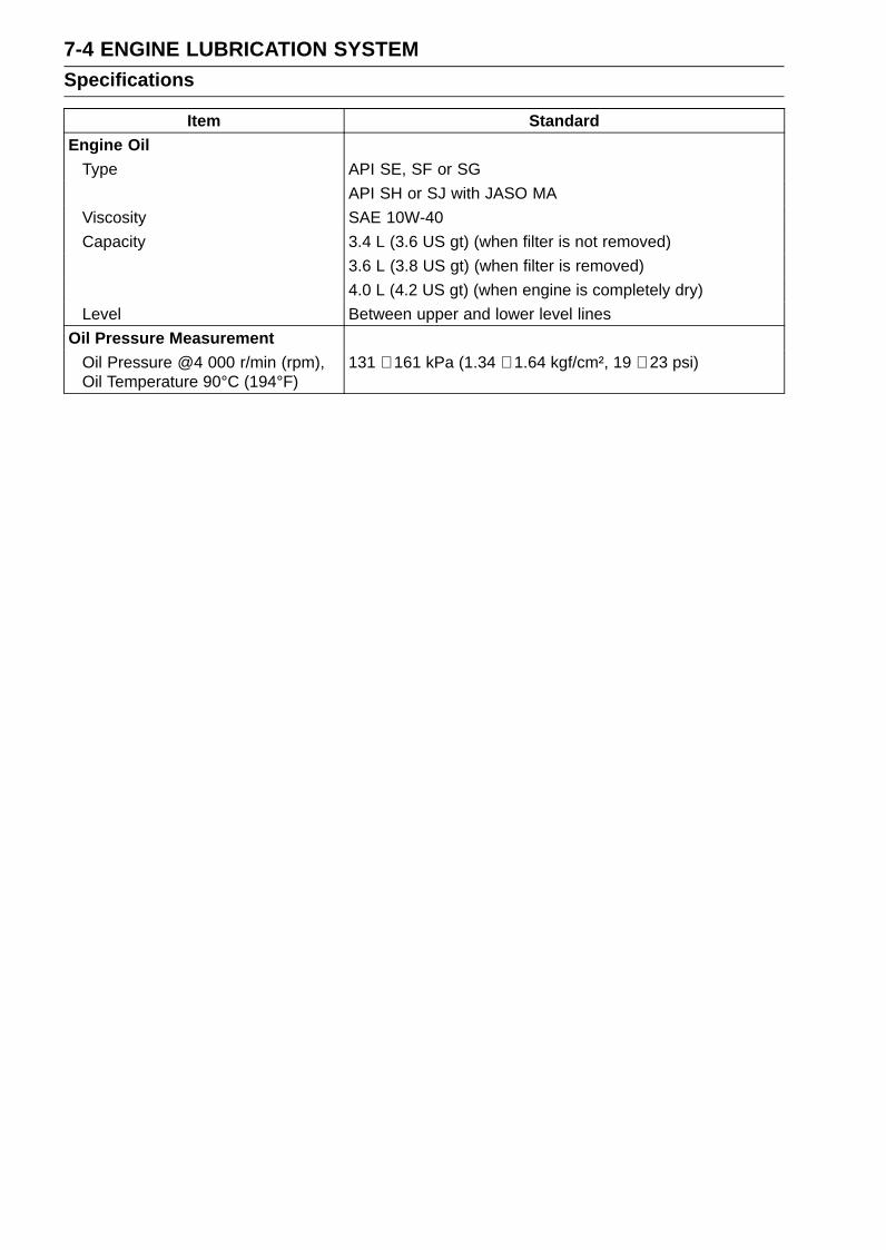
7-4 ENGINE LUBRICATION SYSTEMSpecifications
Item StandardEngine Oil
Type API SE, SF or SG
API SH or SJ with JASO MA
Viscosity SAE 10W-40
Capacity 3.4 L (3.6 US gt) (when filter is not removed)
3.6 L (3.8 US gt) (when filter is removed)
4.0 L (4.2 US gt) (when engine is completely dry)
Level Between upper and lower level lines
Oil Pressure MeasurementOil Pressure @4 000 r/min (rpm),Oil Temperature 90°C (194°F)
131 ∼ 161 kPa (1.34 ∼ 1.64 kgf/cm², 19 ∼ 23 psi)
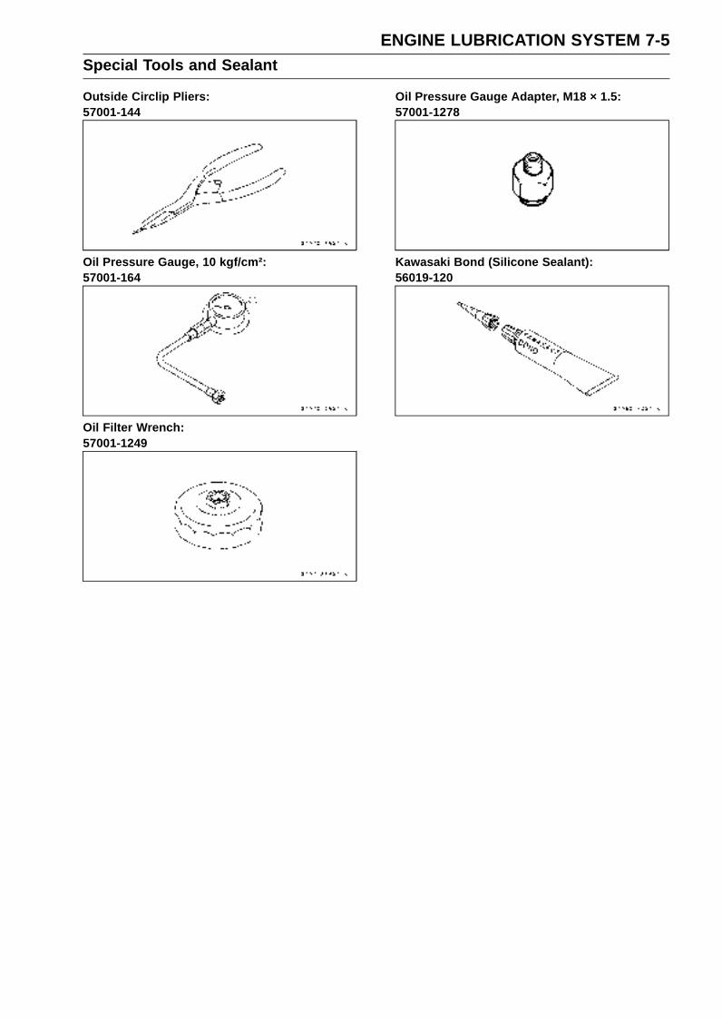
ENGINE LUBRICATION SYSTEM 7-5Special Tools and Sealant
Outside Circlip Pliers:57001-144
Oil Pressure Gauge, 10 kgf/cm²:57001-164
Oil Filter Wrench:57001-1249
Oil Pressure Gauge Adapter, M18 × 1.5:57001-1278
Kawasaki Bond (Silicone Sealant):56019-120
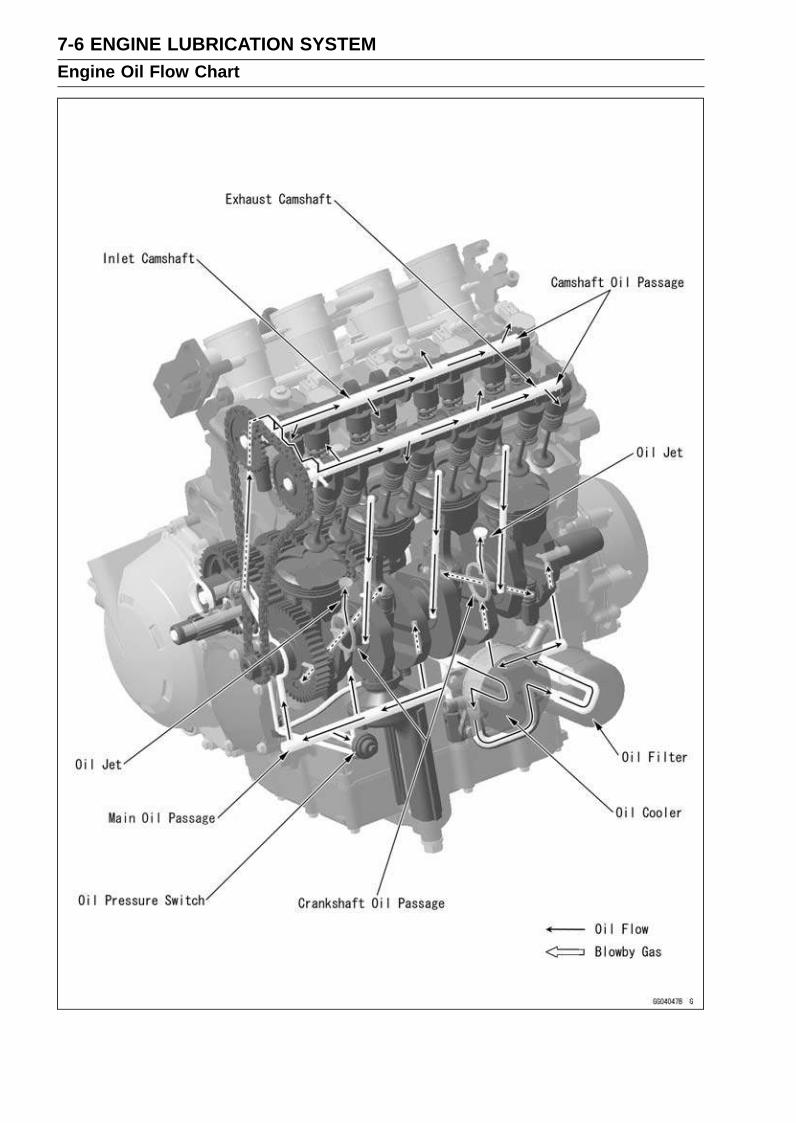
7-6 ENGINE LUBRICATION SYSTEMEngine Oil Flow Chart
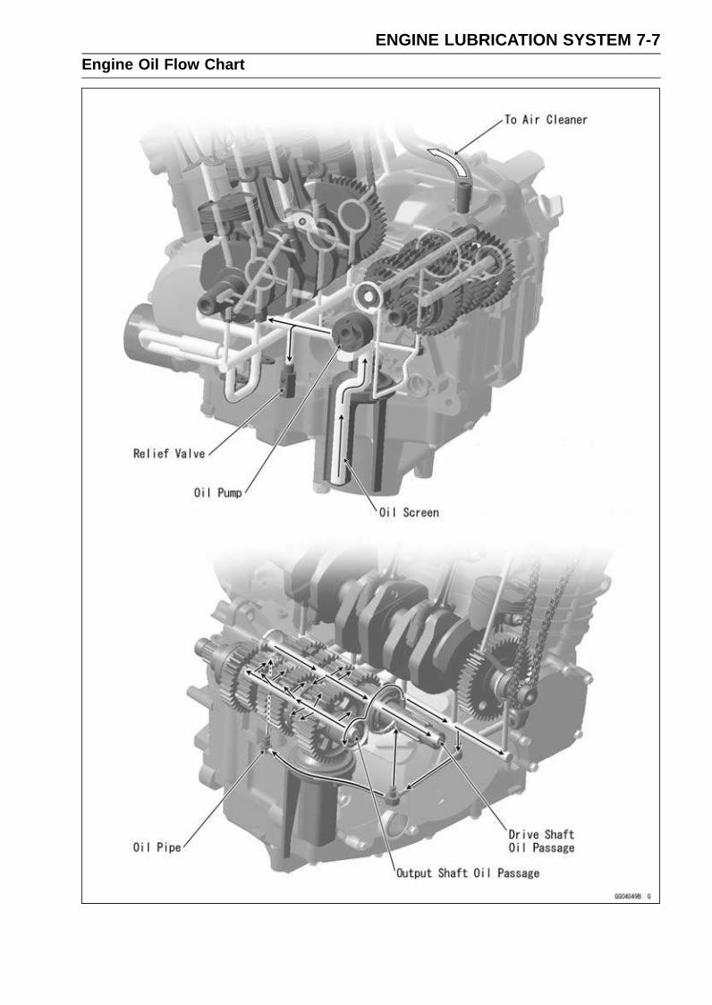
ENGINE LUBRICATION SYSTEM 7-7Engine Oil Flow Chart
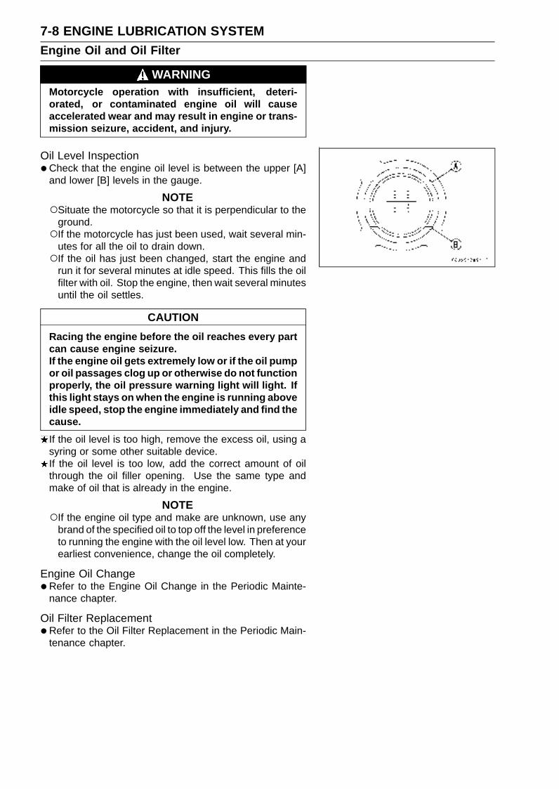
7-8 ENGINE LUBRICATION SYSTEMEngine Oil and Oil Filter
WARNINGMotorcycle operation with insufficient, deteri-orated, or contaminated engine oil will causeaccelerated wear and may result in engine or trans-mission seizure, accident, and injury.
Oil Level Inspection•Check that the engine oil level is between the upper [A]
and lower [B] levels in the gauge.
NOTESituate the motorcycle so that it is perpendicular to the
ground.If the motorcycle has just been used, wait several min-
utes for all the oil to drain down.If the oil has just been changed, start the engine and
run it for several minutes at idle speed. This fills the oilfilter with oil. Stop the engine, then wait several minutesuntil the oil settles.
CAUTION
Racing the engine before the oil reaches every partcan cause engine seizure.If the engine oil gets extremely low or if the oil pumpor oil passages clog up or otherwise do not functionproperly, the oil pressure warning light will light. Ifthis light stays on when the engine is running aboveidle speed, stop the engine immediately and find thecause.
If the oil level is too high, remove the excess oil, using asyring or some other suitable device.If the oil level is too low, add the correct amount of oilthrough the oil filler opening. Use the same type andmake of oil that is already in the engine.
NOTEIf the engine oil type and make are unknown, use any
brand of the specified oil to top off the level in preferenceto running the engine with the oil level low. Then at yourearliest convenience, change the oil completely.
Engine Oil Change•Refer to the Engine Oil Change in the Periodic Mainte-
nance chapter.
Oil Filter Replacement•Refer to the Oil Filter Replacement in the Periodic Main-
tenance chapter.
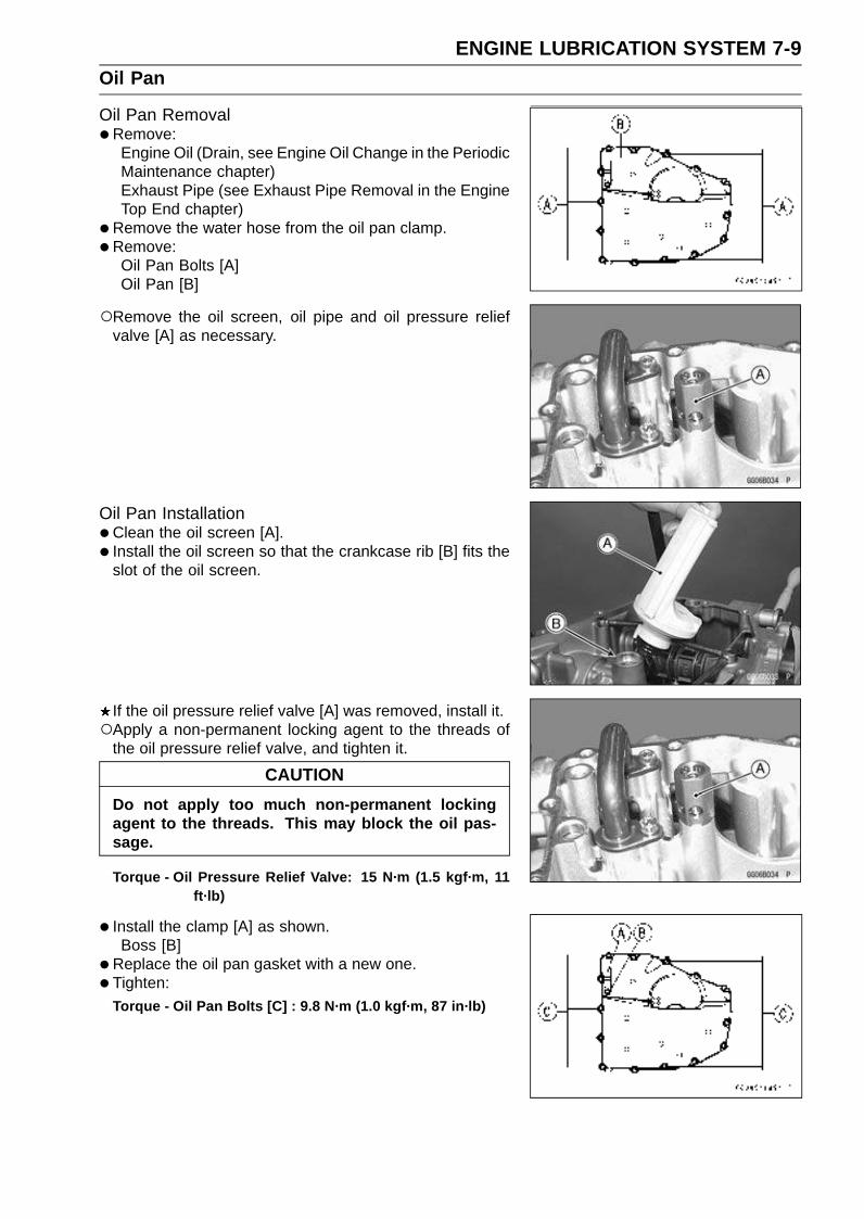
ENGINE LUBRICATION SYSTEM 7-9Oil Pan
Oil Pan Removal•Remove:
Engine Oil (Drain, see Engine Oil Change in the PeriodicMaintenance chapter)Exhaust Pipe (see Exhaust Pipe Removal in the EngineTop End chapter)
•Remove the water hose from the oil pan clamp.
•Remove:Oil Pan Bolts [A]Oil Pan [B]
Remove the oil screen, oil pipe and oil pressure reliefvalve [A] as necessary.
Oil Pan Installation•Clean the oil screen [A].
• Install the oil screen so that the crankcase rib [B] fits theslot of the oil screen.
If the oil pressure relief valve [A] was removed, install it.Apply a non-permanent locking agent to the threads of
the oil pressure relief valve, and tighten it.
CAUTION
Do not apply too much non-permanent lockingagent to the threads. This may block the oil pas-sage.
Torque - Oil Pressure Relief Valve: 15 N·m (1.5 kgf·m, 11ft·lb)
• Install the clamp [A] as shown.Boss [B]
•Replace the oil pan gasket with a new one.
• Tighten:Torque - Oil Pan Bolts [C] : 9.8 N·m (1.0 kgf·m, 87 in·lb)
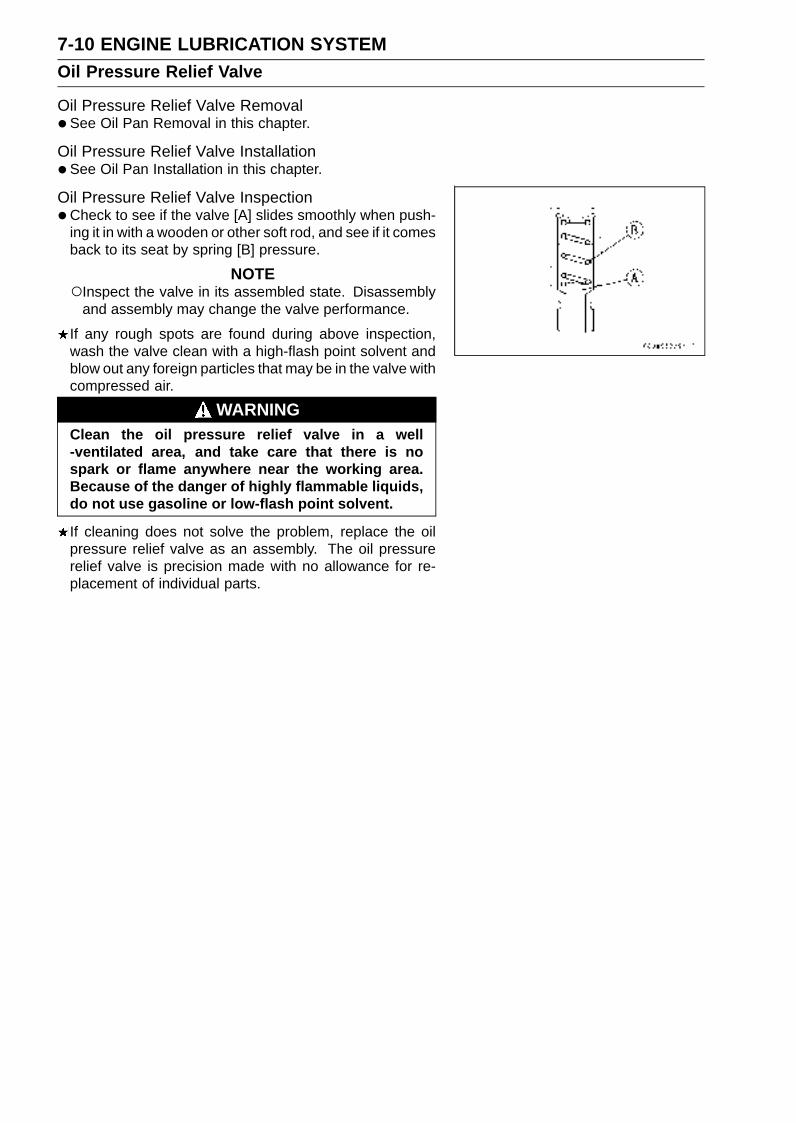
7-10 ENGINE LUBRICATION SYSTEMOil Pressure Relief Valve
Oil Pressure Relief Valve Removal•See Oil Pan Removal in this chapter.
Oil Pressure Relief Valve Installation•See Oil Pan Installation in this chapter.
Oil Pressure Relief Valve Inspection•Check to see if the valve [A] slides smoothly when push-
ing it in with a wooden or other soft rod, and see if it comesback to its seat by spring [B] pressure.
NOTEInspect the valve in its assembled state. Disassembly
and assembly may change the valve performance.
If any rough spots are found during above inspection,wash the valve clean with a high-flash point solvent andblow out any foreign particles that may be in the valve withcompressed air.
WARNINGClean the oil pressure relief valve in a well-ventilated area, and take care that there is nospark or flame anywhere near the working area.Because of the danger of highly flammable liquids,do not use gasoline or low-flash point solvent.
If cleaning does not solve the problem, replace the oilpressure relief valve as an assembly. The oil pressurerelief valve is precision made with no allowance for re-placement of individual parts.

ENGINE LUBRICATION SYSTEM 7-11Oil Pump
Oil Pump Removal•Drain:
Coolant (see Coolant Change in the Periodic Mainte-nance chapter)Engine Oil (see Engine Oil Change in the Periodic Main-tenance chapter)
•Remove:Water Hoses [A]Water Pump Cover Bolts [B]Water Pump Cover
•Remove:Impeller Bolt [A]WasherImpeller [B]
•Remove:Water Pump BodyOil Pump CoverOil (Water) Pump ShaftOuter Rotor [A] and Inner Rotor [B]
NOTEThe oil (water) pump assembly can easily be removed
by installing impeller bolt into the oil (water) pump shaftand pulling them.
Oil Pump Installation• Install the outer rotor [A] into the crankcase.
• Install the pin [B] and inner rotor [C] to the oil (water) pumpshaft [D], and install the assy.Turn the pump shaft so that the slot [E] in its shaft fits onto
the projection [F] of the pump drive gear shaft.

7-12 ENGINE LUBRICATION SYSTEMOil Pump
•Fit the pin [A] of the oil pump cover [B] into the hole [C] inthe crankcase.
• Install:Pins [A]Water Pump Body [B]
• Apply coolant to the surface of the rubber seal on theimpeller.
• Install the impeller [A], washer and impeller bolt [B].Torque - Impeller Bolt: 9.8 N·m (1.0 kgf·m, 87 in·lb)
Pins [C]Water Pump Cover [D]
• Apply a non-permanent locking agent to the threads ofthe water pump cover bolts, and tighten them.Torque - Water Pump Cover Bolts: 12 N·m (1.2 kgf·m, 104
in·lb)
•Align the line [A] of water pump cover and white mark [B]of water hose.
• Tighten:Torque - Water Hose Clamp Screw: 2.0 N·m (0.20 kgf·m, 17
in·lb)
•Route the each hoses and leads correctly (see Cable,Wire, and Hose Routing section in the Appendix chapter).
Oil Pump Drive Gear Removal•Remove:
Clutch (see Clutch Removal in the Clutch chapter)Oil Pan (see Oil Pan Removal in this chapter)Circlip [A] and washer [B]
Special Tool - Outside Circlip Pliers: 57001-144
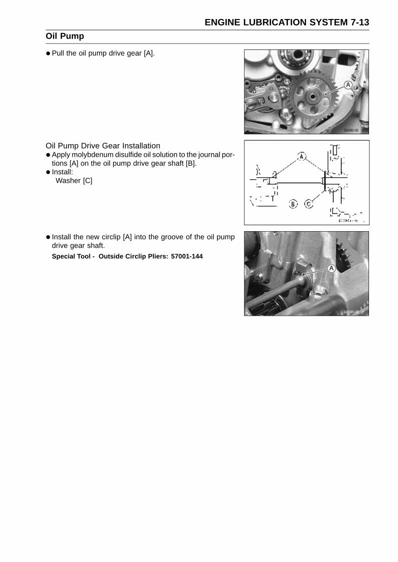
ENGINE LUBRICATION SYSTEM 7-13Oil Pump
•Pull the oil pump drive gear [A].
Oil Pump Drive Gear Installation•Apply molybdenum disulfide oil solution to the journal por-
tions [A] on the oil pump drive gear shaft [B].
• Install:Washer [C]
• Install the new circlip [A] into the groove of the oil pumpdrive gear shaft.
Special Tool - Outside Circlip Pliers: 57001-144

7-14 ENGINE LUBRICATION SYSTEMOil Cooler
Oil Cooler Removal•Remove:
Lower Fairings (see Lower Fairing Removal in the Framechapter)
•Drain:Coolant (see Coolant Change in the Periodic Mainte-nance chapter)Engine Oil (see Engine Oil Change in the Periodic Main-tenance chapter)
•Remove the water hoses [A] from the oil cooler.
• Remove the oil cooler mounting bolts [B], and remove theoil cooler [C].
Oil Cooler Installation•Apply high-temperature grease to the O-ring [A] before
installation.
• Install the oil cooler to the crankcase, and tighten the boltsas shown sequence in the figure.Torque - Oil Cooler Mounting Bolts:
First: 7.8 N·m (0.80 kgf·m, 69 in·lb)Final: 12 N·m (1.2 kgf·m, 104 in·lb)
• Install the water hose so that the white mark [A] faces frontas shown.
• Tighten:Torque - Water Hose Clamp Screws: 2.0 N·m (0.20 kgf·m,
17 in·lb)
•Pour:Engine Oil (see Engine Oil Change in the Periodic Main-tenance chapter)Coolant (see Coolant Change in the Periodic Mainte-nance chapter)
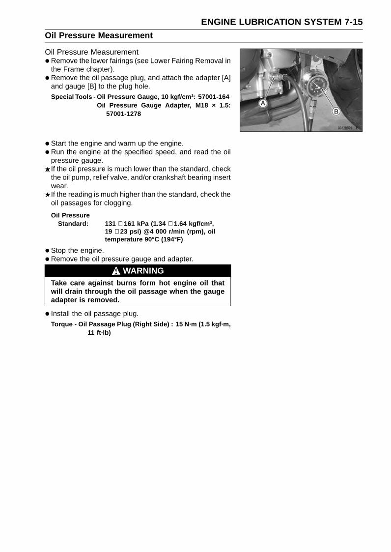
ENGINE LUBRICATION SYSTEM 7-15Oil Pressure Measurement
Oil Pressure Measurement•Remove the lower fairings (see Lower Fairing Removal in
the Frame chapter).
• Remove the oil passage plug, and attach the adapter [A]and gauge [B] to the plug hole.Special Tools - Oil Pressure Gauge, 10 kgf/cm²: 57001-164
Oil Pressure Gauge Adapter, M18 × 1.5:57001-1278
•Start the engine and warm up the engine.
•Run the engine at the specified speed, and read the oilpressure gauge.If the oil pressure is much lower than the standard, checkthe oil pump, relief valve, and/or crankshaft bearing insertwear.If the reading is much higher than the standard, check theoil passages for clogging.
Oil PressureStandard: 131 ∼ 161 kPa (1.34 ∼ 1.64 kgf/cm²,
19 ∼ 23 psi) @4 000 r/min (rpm), oiltemperature 90°C (194°F)
•Stop the engine.
•Remove the oil pressure gauge and adapter.
WARNINGTake care against burns form hot engine oil thatwill drain through the oil passage when the gaugeadapter is removed.
• Install the oil passage plug.
Torque - Oil Passage Plug (Right Side) : 15 N·m (1.5 kgf·m,11 ft·lb)

7-16 ENGINE LUBRICATION SYSTEMOil Pressure Switch
Oil Pressure Switch Removal•Remove:
Lower Fairings (see Lower Fairing Removal in the Framechapter)Engine Oil (Drain, see Engine Oil Change in the PeriodicMaintenance chapter)Switch Cover [A]Switch Terminal [B]Oil Pressure Switch [C]
Oil Pressure Switch Installation•Apply silicone sealant to the threads of the oil pressure
switch and tighten it.Sealant - Kawasaki Bond (Silicone Sealant): 56019-120
Torque - Oil Pressure Switch: 15 N·m (1.5 kgf·m, 11 ft·lb)
• Install the switch lead direction outward.Outside of Engine [A]
• Apply high-temperature grease to the terminal.
• Tighten the terminal bolt.Torque - Oil Pressure Switch Terminal Bolt: 1.5 N·m (0.15
kgf·m, 13 in·lb)
ENGINE REMOVAL/INSTALLATION 8-1
8
Engine Removal/Installation
Table of Contents
Exploded View........................................................................................................................ 8-2Special Tool ............................................................................................................................ 8-4Engine Removal/Installation ................................................................................................... 8-5
Engine Removal................................................................................................................ 8-5Engine Installation............................................................................................................. 8-7

8-2 ENGINE REMOVAL/INSTALLATIONExploded View

ENGINE REMOVAL/INSTALLATION 8-3Exploded View
TorqueNo. Fastener
N·m kgf·m ft·lbRemarks
1 Adjusting Collar Locknut 49 5.0 36 S
2 Lower Engine Mounting Bolt 10 1.0 87 in·lb S
3 Lower Engine Mounting Nut 44 4.5 33 S
4 Middle Engine Mounting Bolt 10 1.0 87 in·lb S
5 Middle Engine Mounting Nut 44 4.5 33 S
6 Upper Engine Mounting Bolts 44 4.5 33 S
S: Follow the specific tightening sequence.
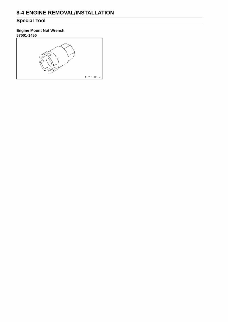
8-4 ENGINE REMOVAL/INSTALLATIONSpecial Tool
Engine Mount Nut Wrench:57001-1450

ENGINE REMOVAL/INSTALLATION 8-5Engine Removal/Installation
Engine Removal•Support the rear part of the swingarm with a stand.
• Squeeze the brake lever slowly and hold it with a band[A].
WARNINGBe sure to hold the front brake when removing theengine, or the motorcycle may fall over. It couldcause an accident and injury.
CAUTION
Be sure to hold the front brake when removing theengine, or the motorcycle may fall over. The engineor the motorcycle could be damaged.
•Drain:Engine Oil (see Engine Oil Change in the Periodic Main-tenance chapter)Coolant (see Coolant Change in the Periodic Mainte-nance chapter)
•Remove:Right and Left Center Fairings (see Center Fairing Re-moval in the Frame chapter)Fuel Tank (see Fuel Tank Removal in the Fuel System(DFI) chapter)Air Cleaner Housing (see Air Cleaner Housing Removalin the Fuel System (DFI) chapter)Throttle Body Assy (see Throttle Body Assy Removal inthe Fuel System (DFI) chapter)Clutch Cable Lower End (see Clutch Cable Removal inthe Clutch chapter)Radiator (see Radiator and Radiator Fan Removal in theCooling System chapter)Exhaust Pipe (see Exhaust Pipe Removal in the EngineTop End chapter)Shift Lever (see Shift Pedal Removal in the Crank-shaft/Transmission chapter)Engine Sprocket (see Engine Sprocket Removal in theFinal Drive chapter)Coolant Reserve Tank (see Coolant Reserve Tank Re-moval in the Cooling System chapter)
• Pull off the connectors from the engine and free the wiringfrom the clamps.
•Remove:Engine Ground Cable Terminal Bolt [A]Starter Motor Lead [B]Connectors [C]Stick Coil Harness Connector (see Stick Coil (IgnitionCoil together with Spark Plug Cap) Removal in the Elec-trical System chapter)

8-6 ENGINE REMOVAL/INSTALLATIONEngine Removal/Installation
•Support the engine with a suitable stand [A].Put a plank [B] onto the suitable stand for engine balance.
•Remove:Right and Left Upper Engine Mounting Bolts [A]
•Using the nut wrench [A], loosen the locknut [B].Special Tool - Engine Mount Nut Wrench: 57001-1450
•Using the Hexagon Wrench, turn the adjusting collar [A]counterclockwise to make the gap between the engineand collar.
• Remove the middle and lower engine mounting nuts.
• Turn the middle and lower mounting bolts [A] clockwise tomake the gap between the collar and frame.
• Pull out the engine mounting bolts from the right side.
•Remove the drive chain from the output shaft.
• Using the stand, take out the engine.
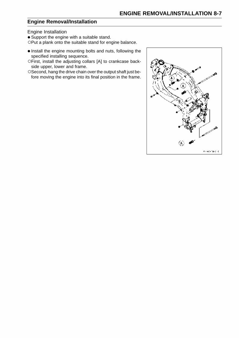
ENGINE REMOVAL/INSTALLATION 8-7Engine Removal/Installation
Engine Installation•Support the engine with a suitable stand.Put a plank onto the suitable stand for engine balance.
• Install the engine mounting bolts and nuts, following thespecified installing sequence.First, install the adjusting collars [A] to crankcase back-
side upper, lower and frame.Second, hang the drive chain over the output shaft just be-
fore moving the engine into its final position in the frame.
8-8 ENGINE REMOVAL/INSTALLATIONEngine Removal/Installation
Third, install the bolts [A] [B] [C] [D] temporally.Fourth, install the lower [A] and middle [B] engine mount-
ing bolts, and tighten the bolts counterclockwise.
NOTETighten the bolts until the clearance between the engine
and collar come to 0 mm (0 in.).
Torque - Lower Engine Mounting Bolt: 10 N·m (1.0 kgf·m,87 in·lb)
Middle Engine Mounting Bolt: 10 N·m (1.0 kgf·m,87 in·lb)
Fifth, tighten the left upper engine mounting bolt [D].Sixth, tighten the lower [E] and middle [F] engine mount-
ing nuts.Seventh, pull out bolt [C] temporally, and tighten the ad-
justing collar [G] counterclockwise until the clearance [H]between the cylinder head and collar come to 0 mm (0in.).Eighth, tighten the right upper engine mounting bolt.Ninth, tighten the adjusting collar locknut [I].
Special Tool - Engine Mount Nut Wrench: 57001-1450
Lastly, tighten the bolts and nuts following the tighteningsequence [1 ∼ 5] as shown.Torque - Left Upper Engine Mounting Bolt [D]: 44 N·m (4.5
kgf·m, 33 ft·lb)Lower Engine Mounting Nut [E]: 44 N·m (4.5 kgf·m,
33 ft·lb)Middle Engine Mounting Nut [F]: 44 N·m (4.5
kgf·m, 33 ft·lb)Right Upper Engine Mounting Bolt [C]: 44 N·m (4.5
kgf·m, 33 ft·lb)Adjusting Collar Locknut [I]: 49 N·m (5.0 kgf·m, 36
ft·lb)

ENGINE REMOVAL/INSTALLATION 8-9Engine Removal/Installation
•Run the leads, cable and hoses correctly (see Cable,Wire, and Hose Routing section in the Appendix chap-ter).
• Install the removed parts (see appropriate chapters).
• Adjust:Throttle Cables (see Throttle Control System Inspectionin the Periodic Maintenance chapter)Clutch Cable (see Clutch Operation Inspection in the Pe-riodic Maintenance chapter)Drive Chain (see Drive Chain Slack Inspection in thePeriodic Maintenance chapter)
• Fill the engine with engine oil (see Engine Oil Change inthe Periodic Maintenance chapter).
• Fill the engine with coolant and bleed the air from the cool-ing system (see Coolant Change in the Periodic Mainte-nance chapter).

CRANKSHAFT/TRANSMISSION 9-1
9
Crankshaft/Transmission
Table of Contents
Exploded View........................................................................................................................ 9-2Specifications ......................................................................................................................... 9-6Special Tools and Sealant ...................................................................................................... 9-8Crankcase Splitting................................................................................................................. 9-9
Crankcase Splitting ........................................................................................................... 9-9Crankcase Assembly ........................................................................................................ 9-10
Crankshaft and Connecting Rods........................................................................................... 9-13Crankshaft Removal ......................................................................................................... 9-13Crankshaft Installation ...................................................................................................... 9-13Connecting Rod Removal ................................................................................................. 9-14Connecting Rod Installation .............................................................................................. 9-14Crankshaft/Connecting Rod Cleaning............................................................................... 9-18Connecting Rod Bend....................................................................................................... 9-18Connecting Rod Twist ....................................................................................................... 9-18Connecting Rod Big End Side Clearance......................................................................... 9-18Connecting Rod Big End Bearing Insert/Crankpin Wear .................................................. 9-19Crankshaft Side Clearance............................................................................................... 9-20Crankshaft Runout ............................................................................................................ 9-21Crankshaft Main Bearing Insert/Journal Wear .................................................................. 9-21
Transmission .......................................................................................................................... 9-23Shift Pedal Removal ......................................................................................................... 9-23Shift Pedal Installation ...................................................................................................... 9-23External Shift Mechanism Removal .................................................................................. 9-24External Shift Mechanism Installation ............................................................................... 9-24External Shift Mechanism Inspection................................................................................ 9-24Transmission Shaft Removal ............................................................................................ 9-25Transmission Shaft Installation ......................................................................................... 9-25Transmission Shaft Disassembly...................................................................................... 9-25Transmission Shaft Assembly........................................................................................... 9-26Shift Drum and Fork Removal........................................................................................... 9-29Shift Drum and Fork Installation........................................................................................ 9-29Shift Drum Disassembly.................................................................................................... 9-29Shift Drum Assembly ........................................................................................................ 9-29Shift Fork Bending ............................................................................................................ 9-29Shift Fork/Gear Groove Wear ........................................................................................... 9-30Shift Fork Guide Pin/Drum Groove Wear.......................................................................... 9-30Gear Dog and Gear Dog Hole Damage............................................................................ 9-30

9-2 CRANKSHAFT/TRANSMISSIONExploded View
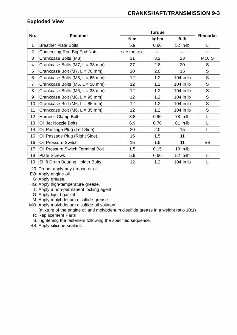
CRANKSHAFT/TRANSMISSION 9-3Exploded View
TorqueNo. Fastener
N·m kgf·m ft·lbRemarks
1 Breather Plate Bolts 5.9 0.60 52 in·lb L
2 Connecting Rod Big End Nuts see the text ← ← ←3 Crankcase Bolts (M8) 31 3.2 23 MO, S
4 Crankcase Bolts (M7, L = 38 mm) 27 2.8 20 S
5 Crankcase Bolt (M7, L = 70 mm) 20 2.0 15 S
6 Crankcase Bolts (M6, L = 65 mm) 12 1.2 104 in·lb S
7 Crankcase Bolts (M6, L = 50 mm) 12 1.2 104 in·lb S
8 Crankcase Bolts (M6, L = 38 mm) 12 1.2 104 in·lb S
9 Crankcase Bolt (M6, L = 95 mm) 12 1.2 104 in·lb S
10 Crankcase Bolt (M6, L = 85 mm) 12 1.2 104 in·lb S
11 Crankcase Bolt (M6, L = 35 mm) 12 1.2 104 in·lb S
12 Harness Clamp Bolt 8.8 0.90 78 in·lb L
13 Oil Jet Nozzle Bolts 6.9 0.70 61 in·lb L
14 Oil Passage Plug (Left Side) 20 2.0 15 L
15 Oil Passage Plug (Right Side) 15 1.5 11
16 Oil Pressure Switch 15 1.5 11 SS
17 Oil Pressure Switch Terminal Bolt 1.5 0.15 13 in·lb
18 Plate Screws 5.9 0.60 52 in·lb L
19 Shift Drum Bearing Holder Bolts 12 1.2 104 in·lb L
20. Do not apply any grease or oil.EO: Apply engine oil.
G: Apply grease.HG: Apply high-temperature grease.
L: Apply a non-permanent locking agent.LG: Apply liquid gasket.M: Apply molybdenum disulfide grease.
MO: Apply molybdenum disulfide oil solution.(mixture of the engine oil and molybdenum disulfide grease in a weight ratio 10:1)
R: Replacement PartsS: Tightening the fasteners following the specified sequence.
SS: Apply silicone sealant.
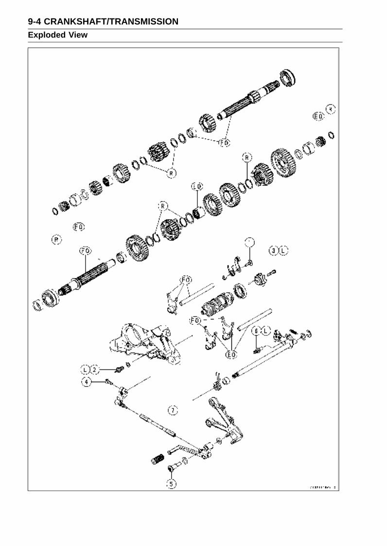
9-4 CRANKSHAFT/TRANSMISSIONExploded View
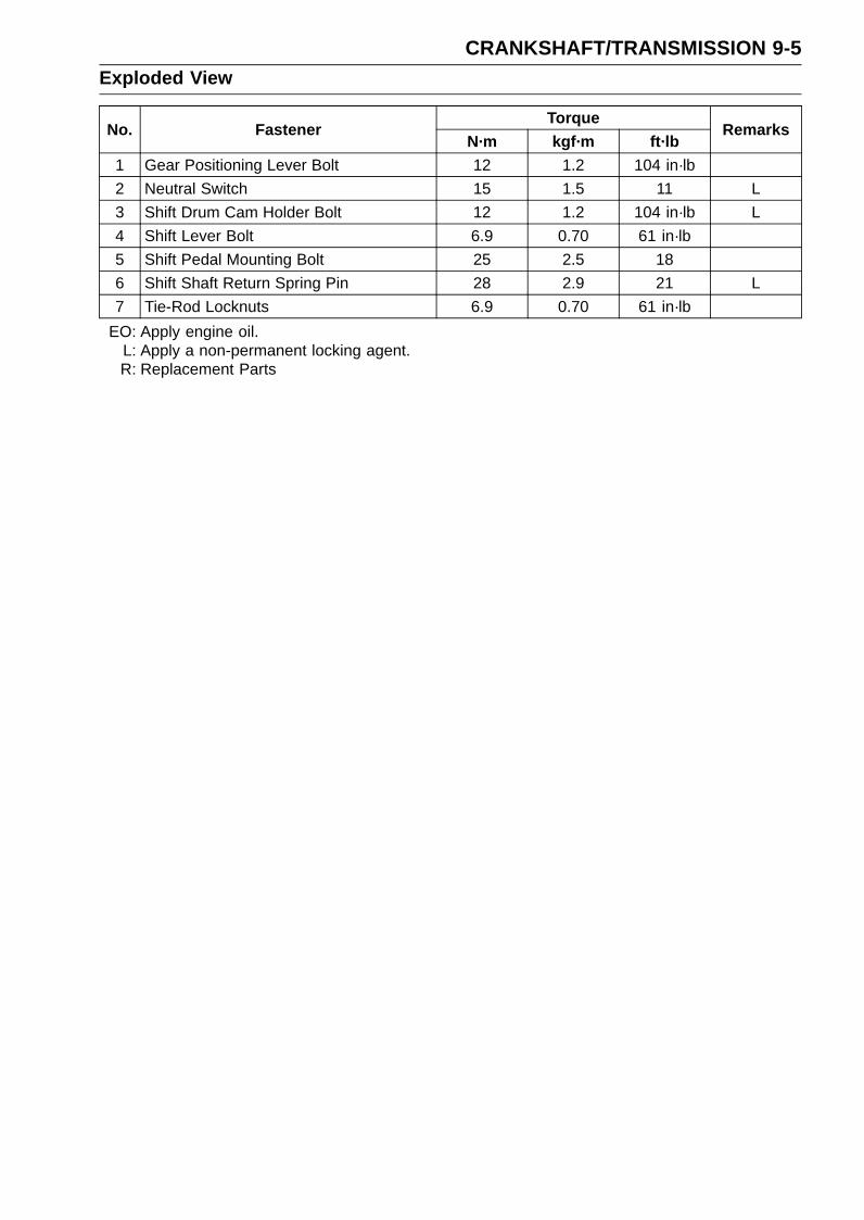
CRANKSHAFT/TRANSMISSION 9-5Exploded View
TorqueNo. Fastener
N·m kgf·m ft·lbRemarks
1 Gear Positioning Lever Bolt 12 1.2 104 in·lb
2 Neutral Switch 15 1.5 11 L
3 Shift Drum Cam Holder Bolt 12 1.2 104 in·lb L
4 Shift Lever Bolt 6.9 0.70 61 in·lb
5 Shift Pedal Mounting Bolt 25 2.5 18
6 Shift Shaft Return Spring Pin 28 2.9 21 L
7 Tie-Rod Locknuts 6.9 0.70 61 in·lb
EO: Apply engine oil.L: Apply a non-permanent locking agent.R: Replacement Parts
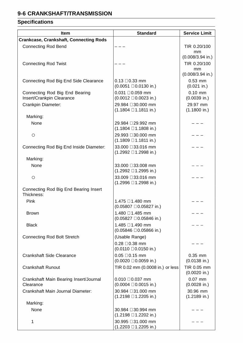
9-6 CRANKSHAFT/TRANSMISSIONSpecifications
Item Standard Service Limit
Crankcase, Crankshaft, Connecting RodsConnecting Rod Bend – – – TIR 0.20/100
mm(0.008/3.94 in.)
Connecting Rod Twist – – – TIR 0.20/100mm
(0.008/3.94 in.)
Connecting Rod Big End Side Clearance 0.13 ∼ 0.33 mm(0.0051 ∼ 0.0130 in.)
0.53 mm(0.021 in.)
Connecting Rod Big End BearingInsert/Crankpin Clearance
0.031 ∼ 0.059 mm(0.0012 ∼ 0.0023 in.)
0.10 mm(0.0039 in.)
Crankpin Diameter: 29.984 ∼ 30.000 mm(1.1804 ∼ 1.1811 in.)
29.97 mm(1.1800 in.)
Marking:
None 29.984 ∼ 29.992 mm(1.1804 ∼ 1.1808 in.)
– – –
29.993 ∼ 30.000 mm(1.1809 ∼ 1.1811 in.)
– – –
Connecting Rod Big End Inside Diameter: 33.000 ∼ 33.016 mm(1.2992 ∼ 1.2998 in.)
– – –
Marking:
None 33.000 ∼ 33.008 mm(1.2992 ∼ 1.2995 in.)
– – –
33.009 ∼ 33.016 mm(1.2996 ∼ 1.2998 in.)
– – –
Connecting Rod Big End Bearing InsertThickness:
Pink 1.475 ∼ 1.480 mm(0.05807 ∼ 0.05827 in.)
– – –
Brown 1.480 ∼ 1.485 mm(0.05827 ∼ 0.05846 in.)
– – –
Black 1.485 ∼ 1.490 mm(0.05846 ∼ 0.05866 in.)
– – –
Connecting Rod Bolt Stretch (Usable Range)
0.28 ∼ 0.38 mm(0.0110 ∼ 0.0150 in.)
– – –
Crankshaft Side Clearance 0.05 ∼ 0.15 mm(0.0020 ∼ 0.0059 in.)
0.35 mm(0.0138 in.)
Crankshaft Runout TIR 0.02 mm (0.0008 in.) or less TIR 0.05 mm(0.0020 in.)
Crankshaft Main Bearing Insert/JournalClearance
0.010 ∼ 0.037 mm(0.0004 ∼ 0.0015 in.)
0.07 mm(0.0028 in.)
Crankshaft Main Journal Diameter: 30.984 ∼ 31.000 mm(1.2198 ∼ 1.2205 in.)
30.96 mm(1.2189 in.)
Marking:
None 30.984 ∼ 30.994 mm(1.2198 ∼ 1.2202 in.)
– – –
1 30.995 ∼ 31.000 mm(1.2203 ∼ 1.2205 in.)
– – –
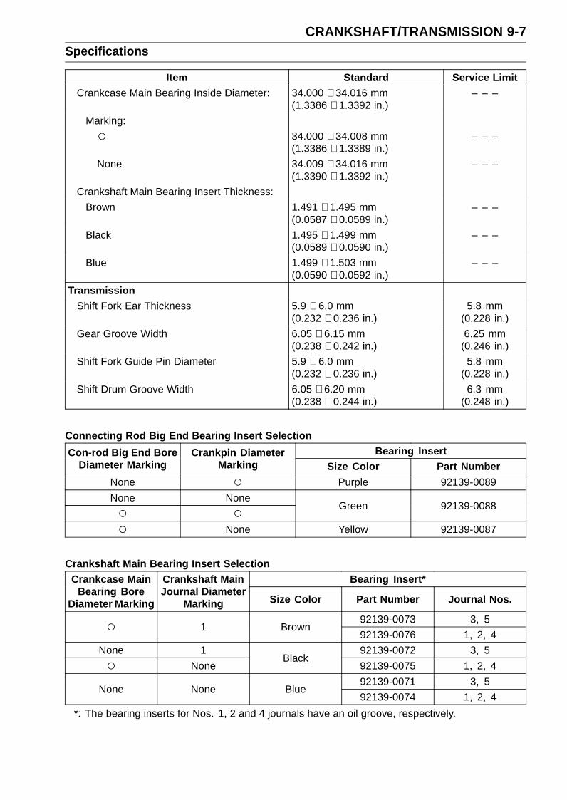
CRANKSHAFT/TRANSMISSION 9-7Specifications
Item Standard Service LimitCrankcase Main Bearing Inside Diameter: 34.000 ∼ 34.016 mm
(1.3386 ∼ 1.3392 in.)– – –
Marking:
34.000 ∼ 34.008 mm(1.3386 ∼ 1.3389 in.)
– – –
None 34.009 ∼ 34.016 mm(1.3390 ∼ 1.3392 in.)
– – –
Crankshaft Main Bearing Insert Thickness:
Brown 1.491 ∼ 1.495 mm(0.0587 ∼ 0.0589 in.)
– – –
Black 1.495 ∼ 1.499 mm(0.0589 ∼ 0.0590 in.)
– – –
Blue 1.499 ∼ 1.503 mm(0.0590 ∼ 0.0592 in.)
– – –
Transmission
Shift Fork Ear Thickness 5.9 ∼ 6.0 mm(0.232 ∼ 0.236 in.)
5.8 mm(0.228 in.)
Gear Groove Width 6.05 ∼ 6.15 mm(0.238 ∼ 0.242 in.)
6.25 mm(0.246 in.)
Shift Fork Guide Pin Diameter 5.9 ∼ 6.0 mm(0.232 ∼ 0.236 in.)
5.8 mm(0.228 in.)
Shift Drum Groove Width 6.05 ∼ 6.20 mm(0.238 ∼ 0.244 in.)
6.3 mm(0.248 in.)
Connecting Rod Big End Bearing Insert SelectionBearing InsertCon-rod Big End Bore
Diameter MarkingCrankpin Diameter
Marking Size Color Part Number
None Purple 92139-0089
None None
Green 92139-0088
None Yellow 92139-0087
Crankshaft Main Bearing Insert SelectionBearing Insert*Crankcase Main
Bearing BoreDiameter Marking
Crankshaft MainJournal Diameter
Marking Size Color Part Number Journal Nos.
92139-0073 3, 5 1 Brown92139-0076 1, 2, 4
None 1 92139-0072 3, 5
NoneBlack
92139-0075 1, 2, 4
92139-0071 3, 5None None Blue
92139-0074 1, 2, 4
*: The bearing inserts for Nos. 1, 2 and 4 journals have an oil groove, respectively.
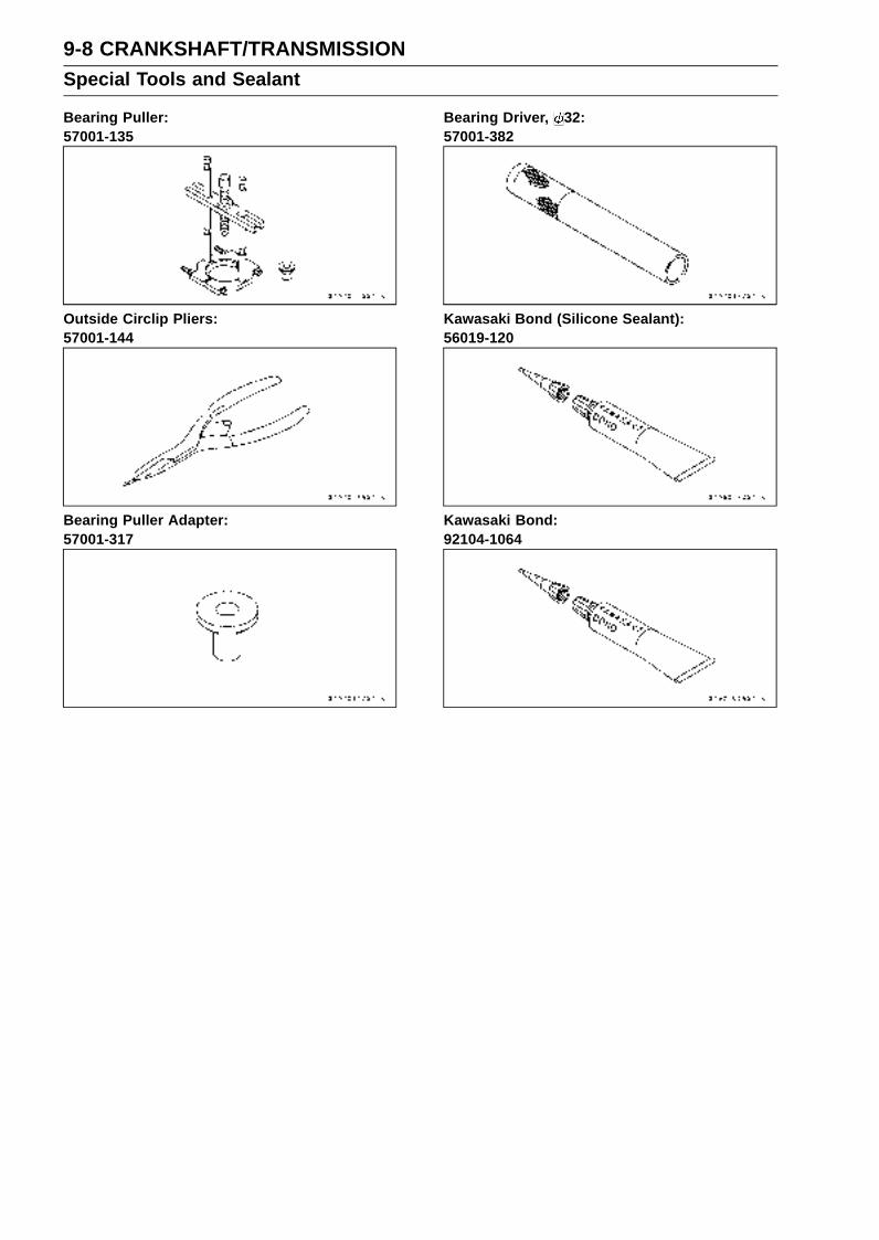
9-8 CRANKSHAFT/TRANSMISSIONSpecial Tools and Sealant
Bearing Puller:57001-135
Outside Circlip Pliers:57001-144
Bearing Puller Adapter:57001-317
Bearing Driver, 32:57001-382
Kawasaki Bond (Silicone Sealant):56019-120
Kawasaki Bond:92104-1064
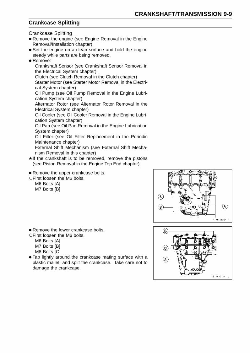
CRANKSHAFT/TRANSMISSION 9-9Crankcase Splitting
Crankcase Splitting•Remove the engine (see Engine Removal in the Engine
Removal/Installation chapter).
• Set the engine on a clean surface and hold the enginesteady while parts are being removed.
•Remove:Crankshaft Sensor (see Crankshaft Sensor Removal inthe Electrical System chapter)Clutch (see Clutch Removal in the Clutch chapter)Starter Motor (see Starter Motor Removal in the Electri-cal System chapter)Oil Pump (see Oil Pump Removal in the Engine Lubri-cation System chapter)Alternator Rotor (see Alternator Rotor Removal in theElectrical System chapter)Oil Cooler (see Oil Cooler Removal in the Engine Lubri-cation System chapter)Oil Pan (see Oil Pan Removal in the Engine LubricationSystem chapter)Oil Filter (see Oil Filter Replacement in the PeriodicMaintenance chapter)External Shift Mechanism (see External Shift Mecha-nism Removal in this chapter)
If the crankshaft is to be removed, remove the pistons(see Piston Removal in the Engine Top End chapter).
• Remove the upper crankcase bolts.First loosen the M6 bolts.
M6 Bolts [A]M7 Bolts [B]
•Remove the lower crankcase bolts.First loosen the M6 bolts.
M6 Bolts [A]M7 Bolts [B]M8 Bolts [C]
• Tap lightly around the crankcase mating surface with aplastic mallet, and split the crankcase. Take care not todamage the crankcase.
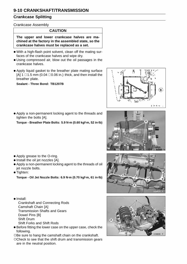
9-10 CRANKSHAFT/TRANSMISSIONCrankcase Splitting
Crankcase Assembly
CAUTION
The upper and lower crankcase halves are ma-chined at the factory in the assembled state, so thecrankcase halves must be replaced as a set.
•With a high-flash point solvent, clean off the mating sur-faces of the crankcase halves and wipe dry.
•Using compressed air, blow out the oil passages in thecrankcase halves.
• Apply liquid gasket to the breather plate mating surface[A] 1 ∼ 1.5 mm (0.04 ∼ 0.06 in.) thick, and then install thebreather plate.
Sealant - Three Bond: TB1207B
•Apply a non-permanent locking agent to the threads andtighten the bolts [A].Torque - Breather Plate Bolts: 5.9 N·m (0.60 kgf·m, 52 in·lb)
•Apply grease to the O-ring.
• Install the oil jet nozzles [A].
• Apply a non-permanent locking agent to the threads of oiljet nozzle bolts.
• Tighten:
Torque - Oil Jet Nozzle Bolts: 6.9 N·m (0.70 kgf·m, 61 in·lb)
• Install:Crankshaft and Connecting RodsCamshaft Chain [A]Transmission Shafts and GearsDowel Pins [B]Shift DrumShift Forks and Shift Rods
•Before fitting the lower case on the upper case, check thefollowing.Be sure to hang the camshaft chain on the crankshaft.Check to see that the shift drum and transmission gears
are in the neutral position.
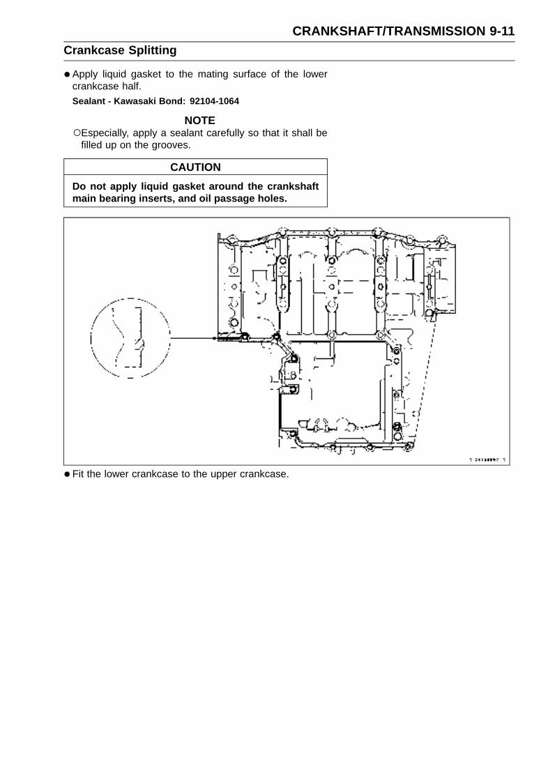
CRANKSHAFT/TRANSMISSION 9-11Crankcase Splitting
•Apply liquid gasket to the mating surface of the lowercrankcase half.Sealant - Kawasaki Bond: 92104-1064
NOTEEspecially, apply a sealant carefully so that it shall be
filled up on the grooves.
CAUTION
Do not apply liquid gasket around the crankshaftmain bearing inserts, and oil passage holes.
•Fit the lower crankcase to the upper crankcase.

9-12 CRANKSHAFT/TRANSMISSIONCrankcase Splitting
•The M8 bolts has a copper plated washer, replace it witha new one.Apply molybdenum disulfide oil to both side [C] of the cop-
per plated washers and threads [B] of M8 bolts [A].
• Tighten the lower crankcase bolts using the followingsteps.Following the sequence numbers on the lower crankcase
half, tighten the M8 bolts [1 ∼ 10] with copper plated wash-ers.L = 71 mm (2.80 in.) [1 ∼ 6]L = 94 mm (3.70 in.) [7 ∼ 10]
Torque - Crankcase Bolts (M8) [A]: 31 N·m (3.2 kgf·m, 23ft·lb)
Install the clamp [B] as shown.Tighten the M7 bolts [C].
Torque - Crankcase Bolts (M7): 27 N·m (2.8 kgf·m, 20 ft·lb)
Tighten the M6 bolts [D].Torque - Crankcase Bolts (M6): 12 N·m (1.2 kgf·m, 104 in·lb)
•Tighten the upper crankcase bolts using the followingsteps.The M6 (L = 95 mm (3.74 in.)) bolts has a copper plated
washer, replace it with a new one.Tighten the M7 bolts.
Torque - Crankcase Bolts (M7) [A]: 20 N·m (2.0 kgf·m, 15ft·lb)
Crankcase Bolts (M6): 12 N·m (1.2 kgf·m, 104 in·lb)
L = 95 mm (3.74 in.) [B]
(with Copper Plated Washers)
L = 85 mm (3.35 in.) [C]
L = 65 mm (2.56 in.) [D]
L = 50 mm (1.97 in.) [E]
L = 35 mm (1.38 in.) [F]
Install the clamp [G] as shown.Apply a non-permanent locking agent to the clamp bolt,
and tighten it.
Torque - Harness Clamp Bolt: 8.8 N·m (0.90 kgf·m, 78 in·lb)
•After tightening all crankcase bolts, check the followingitems.Crankshaft and transmission shafts turn freely.While spinning the output shaft, gears shift smoothly from
the 1st to 6th gear, and 6th to 1st.When the output shaft stays still, the gear can not be
shifted to 2nd gear or other higher gear positions.
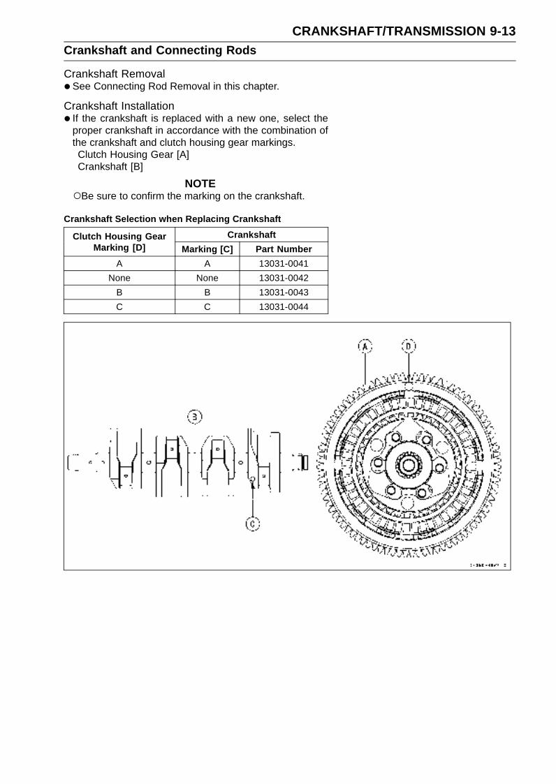
CRANKSHAFT/TRANSMISSION 9-13Crankshaft and Connecting Rods
Crankshaft Removal•See Connecting Rod Removal in this chapter.
Crankshaft Installation• If the crankshaft is replaced with a new one, select the
proper crankshaft in accordance with the combination ofthe crankshaft and clutch housing gear markings.Clutch Housing Gear [A]Crankshaft [B]
NOTEBe sure to confirm the marking on the crankshaft.
Crankshaft Selection when Replacing Crankshaft
CrankshaftClutch Housing GearMarking [D] Marking [C] Part Number
A A 13031-0041
None None 13031-0042
B B 13031-0043
C C 13031-0044

9-14 CRANKSHAFT/TRANSMISSIONCrankshaft and Connecting Rods
NOTEIf the crankshaft is replaced with a new one, refer to
the Connecting Rod Big End Bearing/Crankshaft MainBearing Insert Selection in the Specifications.
CAUTION
If the crankshaft, bearing inserts, or crankcasehalves are replaced with new ones, select the bear-ing inserts and check clearance with a plastigage(press gauge) before assembling engine to be surethe correct bearing inserts are installed.
•Apply molybdenum disulfide oil solution to the crankshaftmain bearing inserts.
• Install the crankshaft with the camshaft chain [A] hangingon it.
Connecting Rod Removal•Split the crankcase (see Crankcase Splitting in this chap-
ter).
• Remove the connecting rod nuts [A].
• Remove the crankshaft.
NOTEMark and record the locations of the connecting rods
and their big end caps so that they can be reassembledin their original positions.
•Remove the connecting rod from the crankshaft.
CAUTION
Discard the connecting rod bolts. To prevent dam-age to the crankpin surfaces, do not allow the con-necting rod bolts to bump against the crankpins.
Connecting Rod Installation
CAUTION
To minimize vibration, the connecting rods shouldhave the same weight mark.
Big End Cap [A]Connecting Rod [B]Weight Mark, Alphabet [C]Diameter Mark [D]: “” mark or no mark
CAUTION
If the connecting rods, big end bearing inserts, orcrankshaft are replaced with new ones, select thebearing insert and check clearance with a plasti-gage (press gauge) before assembling engine to besure the correct bearing inserts are installed.
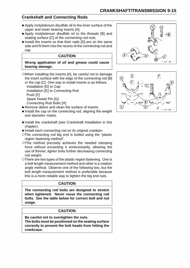
CRANKSHAFT/TRANSMISSION 9-15Crankshaft and Connecting Rods
•Apply molybdenum disulfide oil to the inner surface of theupper and lower bearing inserts [A].
• Apply molybdenum disulfide oil to the threads [B] andseating surface [C] of the connecting rod nuts.
• Install the inserts so that their nails [D] are on the sameside and fit them into the recess of the connecting rod andcap.
CAUTION
Wrong application of oil and grease could causebearing damage.
When installing the inserts [A], be careful not to damagethe insert surface with the edge of the connecting rod [B]or the cap [C]. One way to install inserts is as follows.Installation [D] to CapInstallation [E] to Connecting RodPush [F]Spare Dowel Pin [G]Connecting Rod Bolts [H]
•Remove debris and clean the surface of inserts.
• Install the cap on the connecting rod, aligning the weightand diameter marks.
• Install the crankshaft (see Crankshaft Installation in thischapter).
• Install each connecting rod on its original crankpin.The connecting rod big end is bolted using the “plastic
region fastening method”.This method precisely achieves the needed clamping
force without exceeding it unnecessarily, allowing theuse of thinner, lighter bolts further decreasing connectingrod weight.There are two types of the plastic region fastening. One is
a bolt length measurement method and other is a rotationangle method. Observe one of the following two, but thebolt length measurement method is preferable becausethis is a more reliable way to tighten the big end nuts.
CAUTION
The connecting rod bolts are designed to stretchwhen tightened. Never reuse the connecting rodbolts. See the table below for correct bolt and nutusage.
CAUTION
Be careful not to overtighten the nuts.The bolts must be positioned on the seating surfacecorrectly to prevent the bolt heads from hitting thecrankcase.
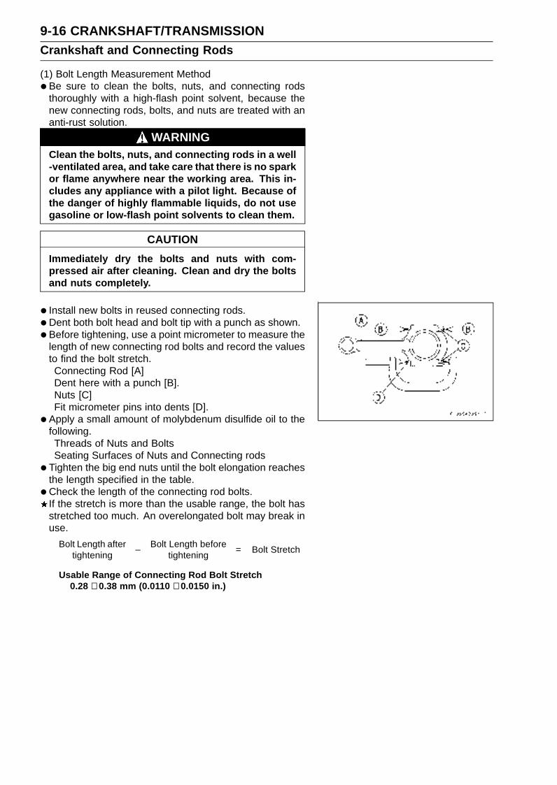
9-16 CRANKSHAFT/TRANSMISSIONCrankshaft and Connecting Rods
(1) Bolt Length Measurement Method
•Be sure to clean the bolts, nuts, and connecting rodsthoroughly with a high-flash point solvent, because thenew connecting rods, bolts, and nuts are treated with ananti-rust solution.
WARNINGClean the bolts, nuts, and connecting rods in a well-ventilated area, and take care that there is no sparkor flame anywhere near the working area. This in-cludes any appliance with a pilot light. Because ofthe danger of highly flammable liquids, do not usegasoline or low-flash point solvents to clean them.
CAUTION
Immediately dry the bolts and nuts with com-pressed air after cleaning. Clean and dry the boltsand nuts completely.
• Install new bolts in reused connecting rods.
•Dent both bolt head and bolt tip with a punch as shown.
• Before tightening, use a point micrometer to measure thelength of new connecting rod bolts and record the valuesto find the bolt stretch.Connecting Rod [A]Dent here with a punch [B].Nuts [C]Fit micrometer pins into dents [D].
• Apply a small amount of molybdenum disulfide oil to thefollowing.Threads of Nuts and BoltsSeating Surfaces of Nuts and Connecting rods
• Tighten the big end nuts until the bolt elongation reachesthe length specified in the table.
•Check the length of the connecting rod bolts.If the stretch is more than the usable range, the bolt hasstretched too much. An overelongated bolt may break inuse.
Bolt Length aftertightening
–Bolt Length before
tightening= Bolt Stretch
Usable Range of Connecting Rod Bolt Stretch0.28 ∼ 0.38 mm (0.0110 ∼ 0.0150 in.)

CRANKSHAFT/TRANSMISSION 9-17Crankshaft and Connecting Rods
(2) Rotation Angle MethodIf you don’t have a point micrometer, you may tighten thenuts using the “Rotation Angle Method”.
• Be sure to clean the bolts, nuts and connecting rods thor-oughly with a high-flash point solvent, because the newconnecting rods, bolts and nuts are treated with an anti-rust solution.
WARNINGClean the bolts, nuts and connecting rods in a well-ventilated area, and take care that there is no sparkor flame anywhere near the working area. This in-cludes any appliance with a pilot light. Because ofthe danger or highly flammable liquids, do not usegasoline or low-flash point solvents to clean them.
CAUTION
Immediately dry the bolts and nuts with com-pressed air after cleaning. Clean and dry the boltsand nuts completely.
• Install new bolts in reused connecting rods.
• Apply a small amount of molybdenum disulfide oil to thefollowing.Threads [A] of Nuts and BoltsSeating Surfaces [B] of Nuts and Connecting Rods
• First, tighten the nuts to the specified torque (see tablebelow).
•Next, tighten the nuts 150° .Mark [A] the connecting rod big end caps and nuts so that
nuts can be turned 150° [B] properly.Mark [A] the connecting rod big end caps and nuts so that
nuts can be turned 180° [C] properly.
ConnectingRod Assy
Bolt, NutTorque + Angle
N·m (kgf·m, in·lb)
Use the boltsattached to new
con-rod.13 (1.3, 113) + 150°
NewAnother new bolts
and nuts13 (1.3, 113) + 180°
UsedReplace the bolts
and nuts withnew ones
13 (1.3, 113) + 180°
CAUTION
Be careful not to overtighten the nuts.
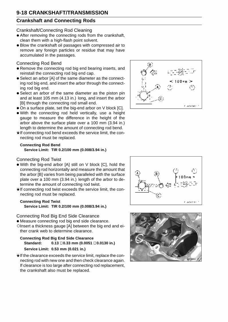
9-18 CRANKSHAFT/TRANSMISSIONCrankshaft and Connecting Rods
Crankshaft/Connecting Rod Cleaning•After removing the connecting rods from the crankshaft,
clean them with a high-flash point solvent.
• Blow the crankshaft oil passages with compressed air toremove any foreign particles or residue that may haveaccumulated in the passages.
Connecting Rod Bend•Remove the connecting rod big end bearing inserts, and
reinstall the connecting rod big end cap.
• Select an arbor [A] of the same diameter as the connect-ing rod big end, and insert the arbor through the connect-ing rod big end.
• Select an arbor of the same diameter as the piston pinand at least 105 mm (4.13 in.) long, and insert the arbor[B] through the connecting rod small end.
•On a surface plate, set the big-end arbor on V block [C].
•With the connecting rod held vertically, use a heightgauge to measure the difference in the height of thearbor above the surface plate over a 100 mm (3.94 in.)length to determine the amount of connecting rod bend.If connecting rod bend exceeds the service limit, the con-necting rod must be replaced.
Connecting Rod BendService Limit: TIR 0.2/100 mm (0.008/3.94 in.)
Connecting Rod Twist•With the big-end arbor [A] still on V block [C], hold the
connecting rod horizontally and measure the amount thatthe arbor [B] varies from being paralleled with the surfaceplate over a 100 mm (3.94 in.) length of the arbor to de-termine the amount of connecting rod twist.If connecting rod twist exceeds the service limit, the con-necting rod must be replaced.
Connecting Rod TwistService Limit: TIR 0.2/100 mm (0.008/3.94 in.)
Connecting Rod Big End Side Clearance•Measure connecting rod big end side clearance.Insert a thickness gauge [A] between the big end and ei-
ther crank web to determine clearance.
Connecting Rod Big End Side ClearanceStandard: 0.13 ∼ 0.33 mm (0.0051 ∼ 0.0130 in.)
Service Limit: 0.53 mm (0.021 in.)
If the clearance exceeds the service limit, replace the con-necting rod with new one and then check clearance again.If clearance is too large after connecting rod replacement,the crankshaft also must be replaced.
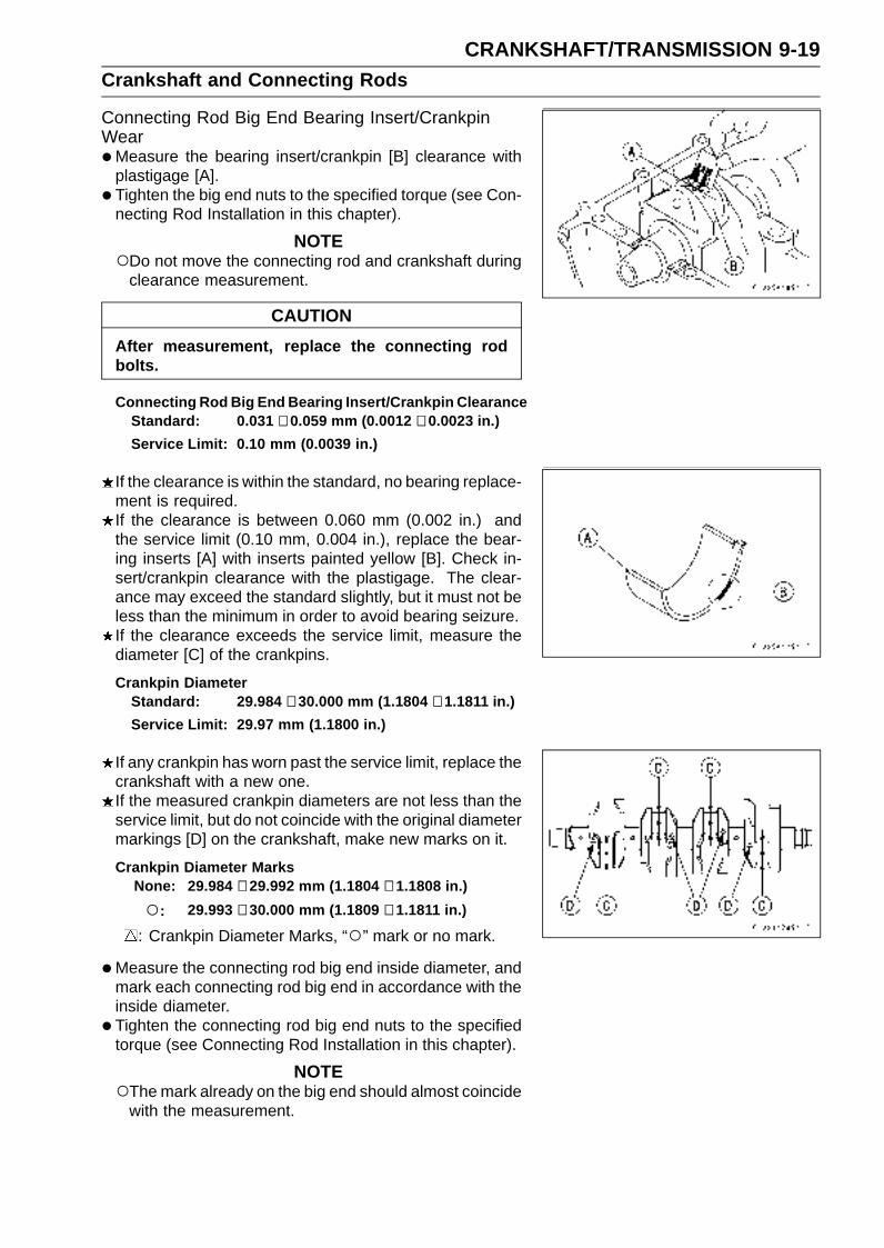
CRANKSHAFT/TRANSMISSION 9-19Crankshaft and Connecting Rods
Connecting Rod Big End Bearing Insert/CrankpinWear•Measure the bearing insert/crankpin [B] clearance with
plastigage [A].
• Tighten the big end nuts to the specified torque (see Con-necting Rod Installation in this chapter).
NOTEDo not move the connecting rod and crankshaft during
clearance measurement.
CAUTION
After measurement, replace the connecting rodbolts.
Connecting Rod Big End Bearing Insert/Crankpin ClearanceStandard: 0.031 ∼ 0.059 mm (0.0012 ∼ 0.0023 in.)
Service Limit: 0.10 mm (0.0039 in.)
If the clearance is within the standard, no bearing replace-ment is required.If the clearance is between 0.060 mm (0.002 in.) andthe service limit (0.10 mm, 0.004 in.), replace the bear-ing inserts [A] with inserts painted yellow [B]. Check in-sert/crankpin clearance with the plastigage. The clear-ance may exceed the standard slightly, but it must not beless than the minimum in order to avoid bearing seizure.If the clearance exceeds the service limit, measure thediameter [C] of the crankpins.
Crankpin DiameterStandard: 29.984 ∼ 30.000 mm (1.1804 ∼ 1.1811 in.)
Service Limit: 29.97 mm (1.1800 in.)
If any crankpin has worn past the service limit, replace thecrankshaft with a new one.If the measured crankpin diameters are not less than theservice limit, but do not coincide with the original diametermarkings [D] on the crankshaft, make new marks on it.
Crankpin Diameter MarksNone: 29.984 ∼ 29.992 mm (1.1804 ∼ 1.1808 in.)
: 29.993 ∼ 30.000 mm (1.1809 ∼ 1.1811 in.)
: Crankpin Diameter Marks, “” mark or no mark.
•Measure the connecting rod big end inside diameter, andmark each connecting rod big end in accordance with theinside diameter.
• Tighten the connecting rod big end nuts to the specifiedtorque (see Connecting Rod Installation in this chapter).
NOTEThe mark already on the big end should almost coincide
with the measurement.

9-20 CRANKSHAFT/TRANSMISSIONCrankshaft and Connecting Rods
Connecting Rod Big End Inside Diameter MarksNone: 33.000 ∼ 33.008 mm (1.2992 ∼ 1.2995 in.)
: 33.009 ∼ 33.016 mm (1.2996 ∼ 1.2998 in.)
Big End Cap [A]Connecting Rod [B]Weight Mark, Alphabet [C]Diameter Mark (Around Weight Mark) [D]: “” mark orno mark
•Select the proper bearing insert [A] in accordance with thecombination of the connecting rod and crankshaft coding.Size Color [B]
Bearing InsertCon-rod BigEnd InsideDiameterMarking
CrankpinDiameterMarking Size Color Part Number
None Purple 92139-0089
None None
Green 92139-0088
None Yellow 92139-0087
• Install the new inserts in the connecting rod and checkinsert/crankpin clearance with the plastigage.If the insert/crankpin clearance is less than the servicelimit, replace the connecting rod bolts and nuts with newones and measure the clearance again.
Crankshaft Side Clearance• Insert a thickness gauge [A] between the crankcase main
bearing and the crank web at the No.2 journal [B] to de-termine clearance.If the clearance exceeds the service limit, replace thecrankcase halves as a set.
NOTEThe upper and lower crankcase halves are machined
at the factory in the assembled state, so the crankcasehalves must be replaced as a set.
Crankshaft Side ClearanceStandard: 0.05 ∼ 0.15 mm (0.0020 ∼ 0.0059 in.)
Service Limit: 0.35 mm (0.0138 in.)

CRANKSHAFT/TRANSMISSION 9-21Crankshaft and Connecting Rods
Crankshaft Runout•Measure the crankshaft runout.
If the measurement exceeds the service limit, replace thecrankshaft.
Crankshaft RunoutStandard: TIR 0.02 mm (0.0008 in.) or less
Service Limit: TIR 0.05 mm (0.0020 in.)
Crankshaft Main Bearing Insert/Journal Wear•Using a plastigage (press gauge) [A], measure the bear-
ing insert/journal [B] clearance.
NOTETighten the crankcase bolts to the specified torque (see
Crankcase Assembly in this chapter).Do not turn the crankshaft during clearance measure-
ment.Journal clearance less than 0.025 mm (0.00098 in.) can
not be measured by plastigage, however, using genuineparts maintains the minimum standard clearance.
Crankshaft Main Bearing Insert/Journal ClearanceStandard: 0.010 ∼ 0.037 mm (0.0004 ∼ 0.0015 in.)
Service Limit: 0.07 mm (0.0028 in.)
If the clearance is within the standard, no bearing replace-ment is required.If the clearance is between 0.038 mm (0.0015 in.) and theservice limit (0.07 mm, 0.0028 in.), replace the bearing in-serts [A] with inserts painted blue [B]. Check insert/journalclearance with the plastigage. The clearance may exceedthe standard slightly, but it must not be less than the min-imum in order to avoid bearing seizure.If the clearance exceeds the service limit, measure thediameter [C] of the crankshaft main journal.
Crankshaft Main Journal DiameterStandard: 30.984 ∼ 31.000 mm (1.2198 ∼ 1.2202 in.)
Service Limit: 30.96 mm (1.2189 in.)
If any journal has worn past the service limit, replace thecrankshaft with a new one.If the measured journal diameters are not less than theservice limit, but do not coincide with the original diametermarkings [D] on the crankshaft, make new marks on it.
Crankshaft Main Journal Diameter MarksNone: 30.984 ∼ 30.992 mm (1.2198 ∼ 1.2202 in.)
1: 30.993 ∼ 31.000 mm (1.2203 ∼ 1.2205 in.)
: Crankshaft Main Journal Diameter Marks, “1” markor no mark.
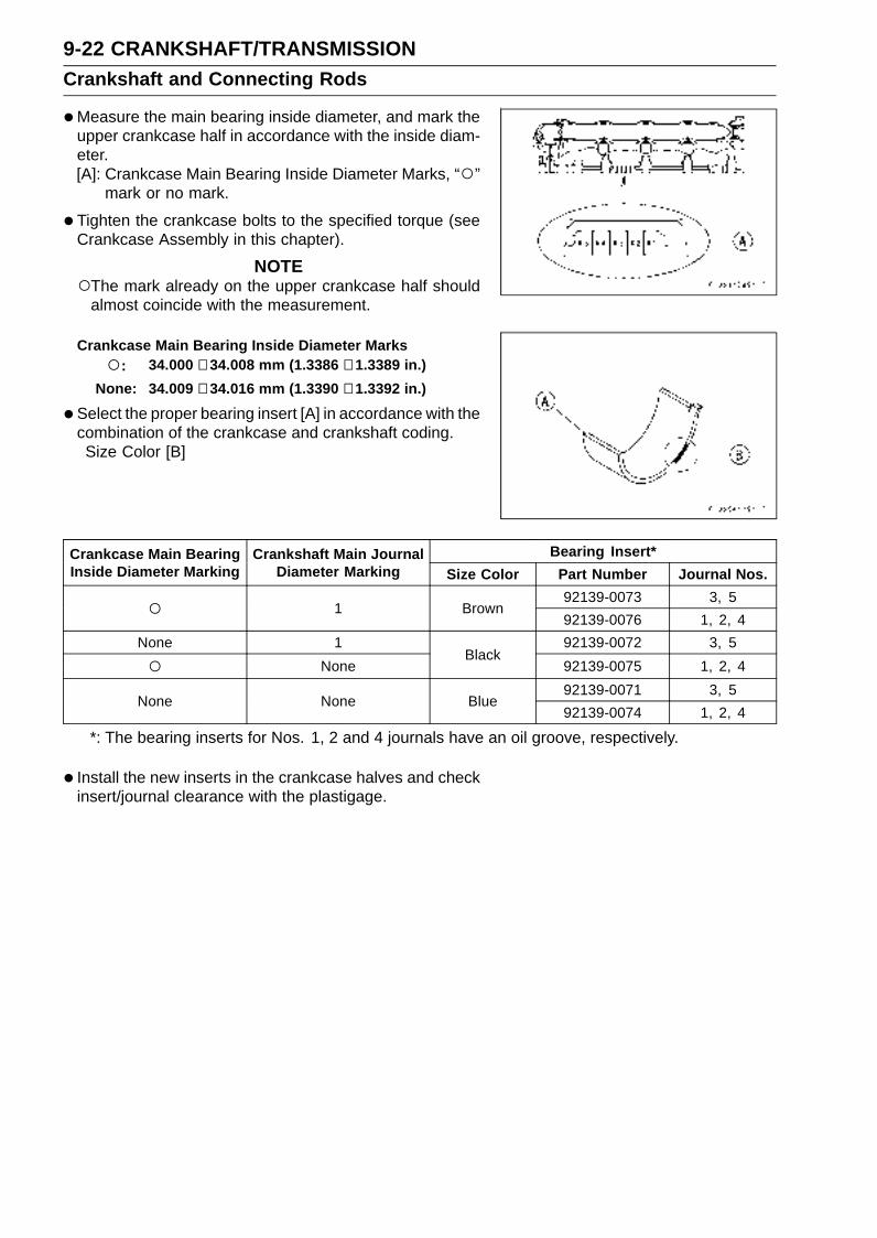
9-22 CRANKSHAFT/TRANSMISSIONCrankshaft and Connecting Rods
•Measure the main bearing inside diameter, and mark theupper crankcase half in accordance with the inside diam-eter.[A]: Crankcase Main Bearing Inside Diameter Marks, “”
mark or no mark.
• Tighten the crankcase bolts to the specified torque (seeCrankcase Assembly in this chapter).
NOTEThe mark already on the upper crankcase half should
almost coincide with the measurement.
Crankcase Main Bearing Inside Diameter Marks
: 34.000 ∼ 34.008 mm (1.3386 ∼ 1.3389 in.)
None: 34.009 ∼ 34.016 mm (1.3390 ∼ 1.3392 in.)
•Select the proper bearing insert [A] in accordance with thecombination of the crankcase and crankshaft coding.Size Color [B]
Bearing Insert*Crankcase Main BearingInside Diameter Marking
Crankshaft Main JournalDiameter Marking Size Color Part Number Journal Nos.
92139-0073 3, 5 1 Brown92139-0076 1, 2, 4
None 1 92139-0072 3, 5
NoneBlack
92139-0075 1, 2, 4
92139-0071 3, 5None None Blue
92139-0074 1, 2, 4
*: The bearing inserts for Nos. 1, 2 and 4 journals have an oil groove, respectively.
• Install the new inserts in the crankcase halves and checkinsert/journal clearance with the plastigage.
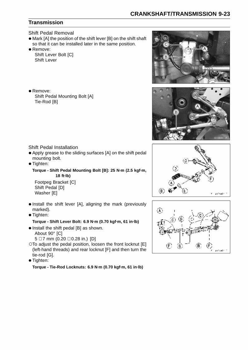
CRANKSHAFT/TRANSMISSION 9-23Transmission
Shift Pedal Removal•Mark [A] the position of the shift lever [B] on the shift shaft
so that it can be installed later in the same position.
•Remove:Shift Lever Bolt [C]Shift Lever
•Remove:Shift Pedal Mounting Bolt [A]Tie-Rod [B]
Shift Pedal Installation•Apply grease to the sliding surfaces [A] on the shift pedal
mounting bolt.
• Tighten:Torque - Shift Pedal Mounting Bolt [B]: 25 N·m (2.5 kgf·m,
18 ft·lb)
Footpeg Bracket [C]Shift Pedal [D]Washer [E]
• Install the shift lever [A], aligning the mark (previouslymarked).
• Tighten:
Torque - Shift Lever Bolt: 6.9 N·m (0.70 kgf·m, 61 in·lb)
• Install the shift pedal [B] as shown.About 90° [C]5 ∼ 7 mm (0.20 ∼ 0.28 in.) [D]
To adjust the pedal position, loosen the front locknut [E](left-hand threads) and rear locknut [F] and then turn thetie-rod [G].
• Tighten:Torque - Tie-Rod Locknuts: 6.9 N·m (0.70 kgf·m, 61 in·lb)
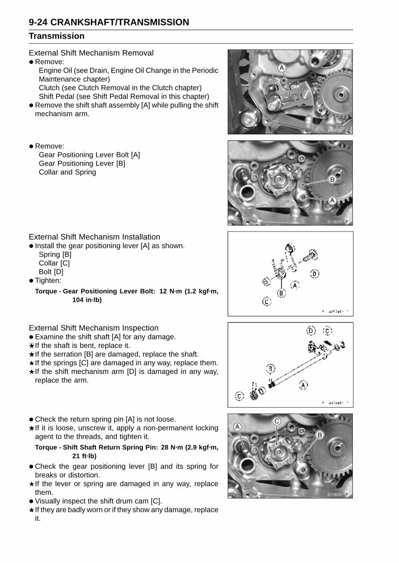
9-24 CRANKSHAFT/TRANSMISSIONTransmission
External Shift Mechanism Removal•Remove:
Engine Oil (see Drain, Engine Oil Change in the PeriodicMaintenance chapter)Clutch (see Clutch Removal in the Clutch chapter)Shift Pedal (see Shift Pedal Removal in this chapter)
•Remove the shift shaft assembly [A] while pulling the shiftmechanism arm.
•Remove:Gear Positioning Lever Bolt [A]Gear Positioning Lever [B]Collar and Spring
External Shift Mechanism Installation• Install the gear positioning lever [A] as shown.
Spring [B]Collar [C]Bolt [D]
• Tighten:Torque - Gear Positioning Lever Bolt: 12 N·m (1.2 kgf·m,
104 in·lb)
External Shift Mechanism Inspection•Examine the shift shaft [A] for any damage.
If the shaft is bent, replace it.If the serration [B] are damaged, replace the shaft.If the springs [C] are damaged in any way, replace them.If the shift mechanism arm [D] is damaged in any way,replace the arm.
•Check the return spring pin [A] is not loose.If it is loose, unscrew it, apply a non-permanent lockingagent to the threads, and tighten it.Torque - Shift Shaft Return Spring Pin: 28 N·m (2.9 kgf·m,
21 ft·lb)
•Check the gear positioning lever [B] and its spring forbreaks or distortion.If the lever or spring are damaged in any way, replacethem.
•Visually inspect the shift drum cam [C].If they are badly worn or if they show any damage, replaceit.

CRANKSHAFT/TRANSMISSION 9-25Transmission
Transmission Shaft Removal•Split the crankcase (see Crankcase Splitting in this chap-
ter).
• Remove the drive shaft [A] and output shaft [B].
Transmission Shaft Installation•Check to see that the set ring [A] and set pin [B] are in
place.
• Install the drive shaft and output shaft into the uppercrankcase half.
• Apply molybdenum disulfide oil to the sliding surfaces ofthe gears and bearings.The bearing set pin and ring must match properly with the
hole or groove in the bearing outer races. When they areproperly matched, there is no clearance [A] between thecrankcase and the bearing outer races.
• Assemble the crankcase.
• Press in the oil seal [A] onto collar [B] so that the surfaceof the oil seal is flush with the counterbore bottom surface[C] of the crankcase.
Transmission Shaft Disassembly•Remove the transmission shafts (see Transmission Shaft
Removal in this chapter).
• Remove the circlips, disassemble the transmissionshafts.Special Tool - Outside Circlip Pliers: 57001-144
•The 5th gear [A] on the output shaft has three steel ballsassembled into it for the positive neutral finder mecha-nism. Remove the 5th gear.Set the output shaft in a vertical position holding the 3rd
gear [C].Spin the 5th gear quickly [B] and pull it off upward.

9-26 CRANKSHAFT/TRANSMISSIONTransmission
•Remove the ball bearing [A] from each shafts.Special Tools - Bearing Puller [B]: 57001-135
Bearing Puller Adapter [C]: 57001-317
•Discard the bearing.
Transmission Shaft Assembly• Install the ball bearing on the drive shaft [A] with the
groove [B] toward the clutch side using the bearingdriver.
• Install the ball bearing and collar on the output shaft [C]using the bearing driver.Special Tool - Bearing Driver, 32: 57001-382
•Apply molybdenum disulfide oil to the sliding surfaces ofthe gears and shafts.
• Install the gear bushings [A] on the shaft with their holes[B] aligned.
•Replace any circlips removed with new ones.
• Install the circlips [A] so that the opening [B] is alignedwith a spline groove [C].
• Check that each gear spins or slides freely on the trans-mission shafts without binding after assembly.
• The drive shaft gears can be recognized by size: the gearwith the smallest diameter is 1st gear, and the largest oneis 6th gear. Be sure that all parts are put back in the cor-rect sequence and all circlips and washers are properly inplace.
• Install the 3rd/4th gear onto the drive shaft with their oilholes aligned.
• The output shaft gears can be recognized by size: thegear with the largest diameter is 1st gear, and the small-est one is 6th gear. Be sure that all parts are put backin the correct sequence and all circlips and washers areproperly in place.
• Install the 5th and 6th gears onto the output shaft withtheir oil holes aligned.
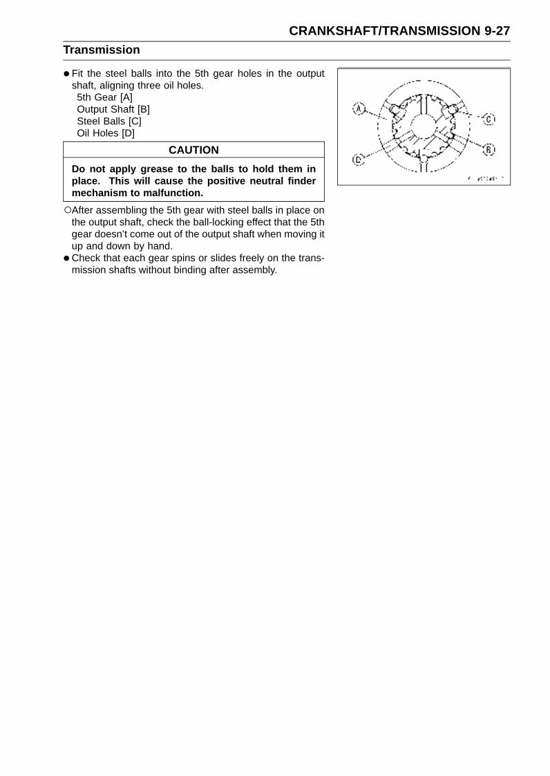
CRANKSHAFT/TRANSMISSION 9-27Transmission
•Fit the steel balls into the 5th gear holes in the outputshaft, aligning three oil holes.5th Gear [A]Output Shaft [B]Steel Balls [C]Oil Holes [D]
CAUTION
Do not apply grease to the balls to hold them inplace. This will cause the positive neutral findermechanism to malfunction.
After assembling the 5th gear with steel balls in place onthe output shaft, check the ball-locking effect that the 5thgear doesn’t come out of the output shaft when moving itup and down by hand.
•Check that each gear spins or slides freely on the trans-mission shafts without binding after assembly.
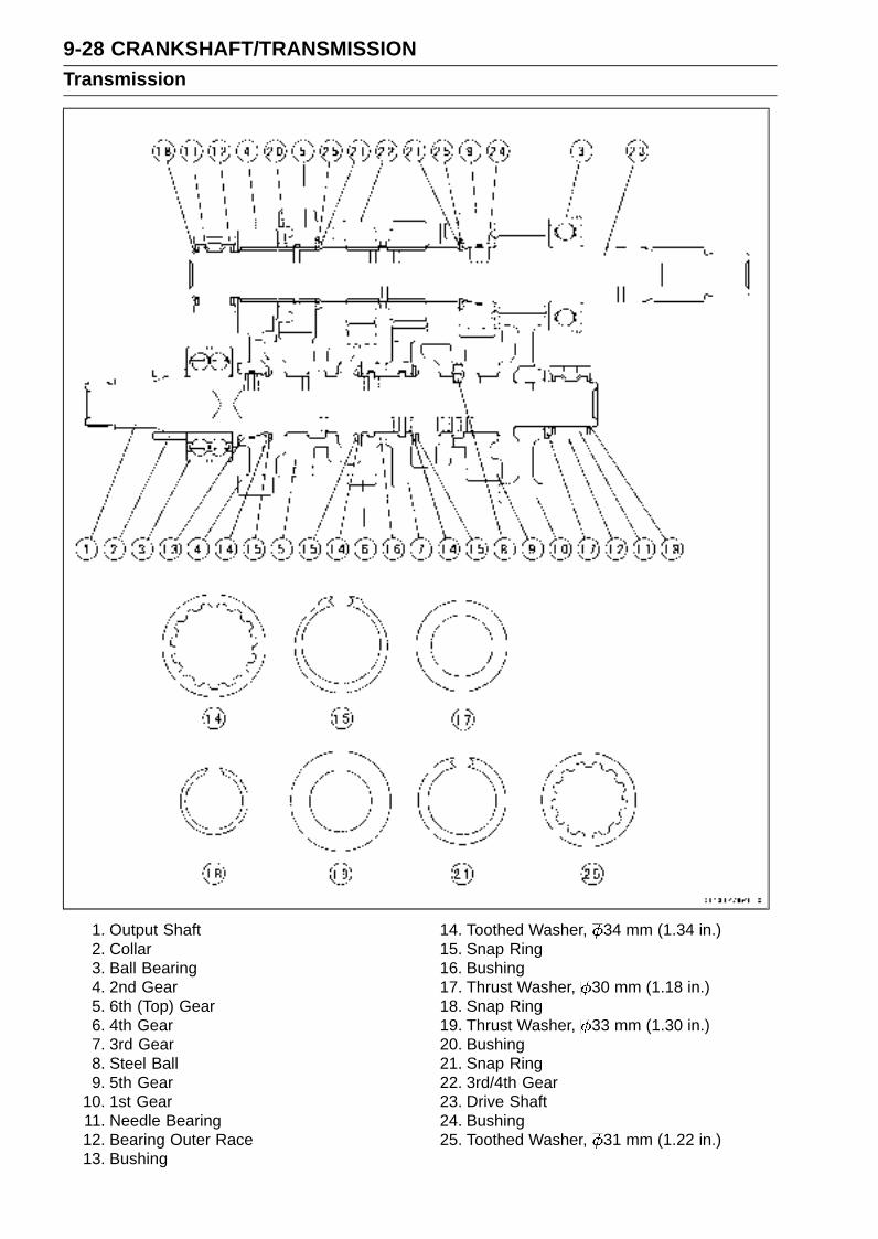
9-28 CRANKSHAFT/TRANSMISSIONTransmission
1. Output Shaft2. Collar3. Ball Bearing4. 2nd Gear5. 6th (Top) Gear6. 4th Gear7. 3rd Gear8. Steel Ball9. 5th Gear
10. 1st Gear11. Needle Bearing12. Bearing Outer Race13. Bushing
14. Toothed Washer, 34 mm (1.34 in.)15. Snap Ring16. Bushing17. Thrust Washer, 30 mm (1.18 in.)18. Snap Ring19. Thrust Washer, 33 mm (1.30 in.)20. Bushing21. Snap Ring22. 3rd/4th Gear23. Drive Shaft24. Bushing25. Toothed Washer, 31 mm (1.22 in.)
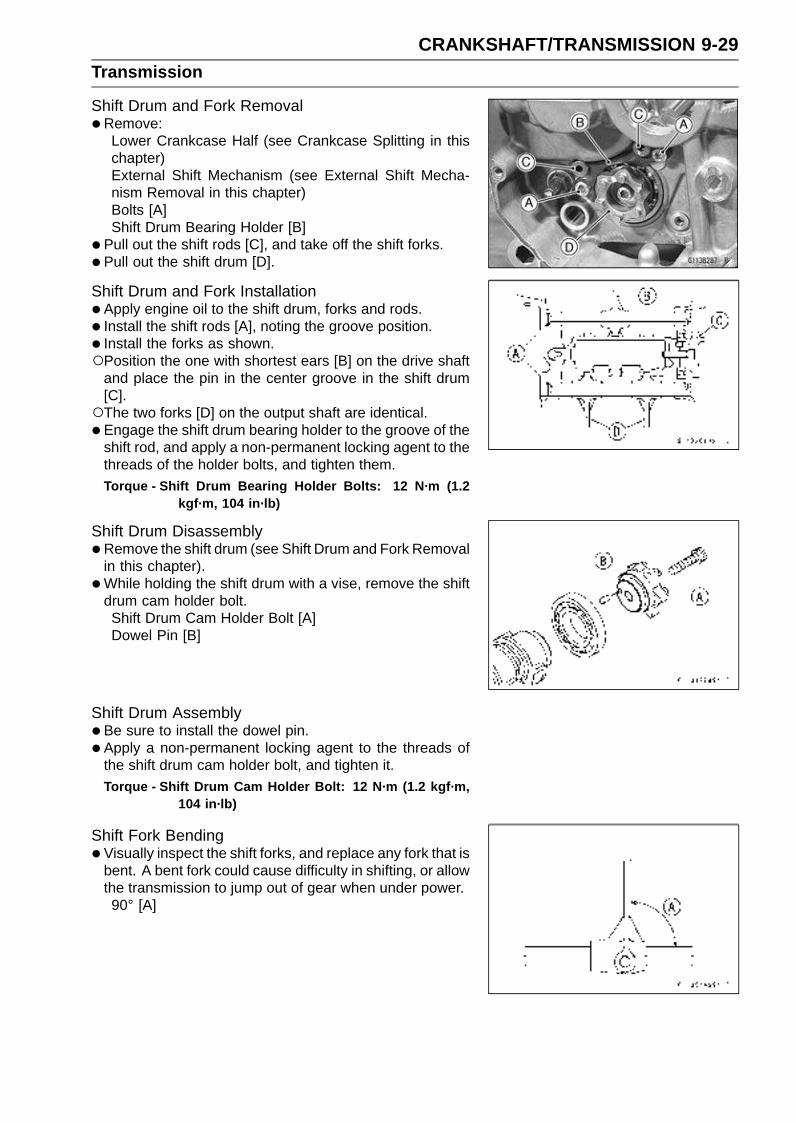
CRANKSHAFT/TRANSMISSION 9-29Transmission
Shift Drum and Fork Removal•Remove:
Lower Crankcase Half (see Crankcase Splitting in thischapter)External Shift Mechanism (see External Shift Mecha-nism Removal in this chapter)Bolts [A]Shift Drum Bearing Holder [B]
• Pull out the shift rods [C], and take off the shift forks.
• Pull out the shift drum [D].
Shift Drum and Fork Installation•Apply engine oil to the shift drum, forks and rods.
• Install the shift rods [A], noting the groove position.
• Install the forks as shown.Position the one with shortest ears [B] on the drive shaft
and place the pin in the center groove in the shift drum[C].The two forks [D] on the output shaft are identical.
• Engage the shift drum bearing holder to the groove of theshift rod, and apply a non-permanent locking agent to thethreads of the holder bolts, and tighten them.Torque - Shift Drum Bearing Holder Bolts: 12 N·m (1.2
kgf·m, 104 in·lb)
Shift Drum Disassembly•Remove the shift drum (see Shift Drum and Fork Removal
in this chapter).
•While holding the shift drum with a vise, remove the shiftdrum cam holder bolt.Shift Drum Cam Holder Bolt [A]Dowel Pin [B]
Shift Drum Assembly•Be sure to install the dowel pin.
• Apply a non-permanent locking agent to the threads ofthe shift drum cam holder bolt, and tighten it.Torque - Shift Drum Cam Holder Bolt: 12 N·m (1.2 kgf·m,
104 in·lb)
Shift Fork Bending•Visually inspect the shift forks, and replace any fork that is
bent. A bent fork could cause difficulty in shifting, or allowthe transmission to jump out of gear when under power.90° [A]
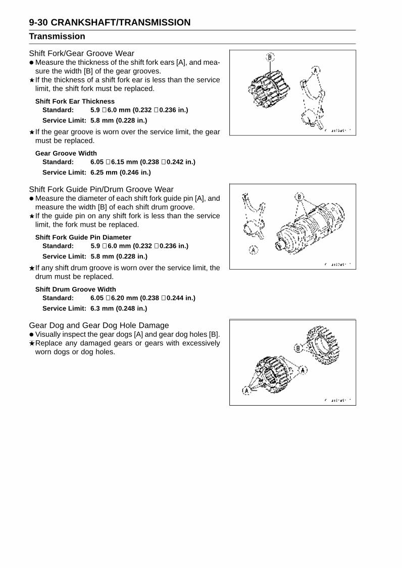
9-30 CRANKSHAFT/TRANSMISSIONTransmission
Shift Fork/Gear Groove Wear•Measure the thickness of the shift fork ears [A], and mea-
sure the width [B] of the gear grooves.If the thickness of a shift fork ear is less than the servicelimit, the shift fork must be replaced.
Shift Fork Ear ThicknessStandard: 5.9 ∼ 6.0 mm (0.232 ∼ 0.236 in.)
Service Limit: 5.8 mm (0.228 in.)
If the gear groove is worn over the service limit, the gearmust be replaced.
Gear Groove WidthStandard: 6.05 ∼ 6.15 mm (0.238 ∼ 0.242 in.)
Service Limit: 6.25 mm (0.246 in.)
Shift Fork Guide Pin/Drum Groove Wear•Measure the diameter of each shift fork guide pin [A], and
measure the width [B] of each shift drum groove.If the guide pin on any shift fork is less than the servicelimit, the fork must be replaced.
Shift Fork Guide Pin DiameterStandard: 5.9 ∼ 6.0 mm (0.232 ∼ 0.236 in.)
Service Limit: 5.8 mm (0.228 in.)
If any shift drum groove is worn over the service limit, thedrum must be replaced.
Shift Drum Groove WidthStandard: 6.05 ∼ 6.20 mm (0.238 ∼ 0.244 in.)
Service Limit: 6.3 mm (0.248 in.)
Gear Dog and Gear Dog Hole Damage•Visually inspect the gear dogs [A] and gear dog holes [B].
Replace any damaged gears or gears with excessivelyworn dogs or dog holes.
WHEELS/TIRES 10-1
10
Wheels/Tires
Table of Contents
Exploded View........................................................................................................................ 10-2Specifications ......................................................................................................................... 10-4Special Tools .......................................................................................................................... 10-5Wheels (Rims) ........................................................................................................................ 10-6
Front Wheel Removal ....................................................................................................... 10-6Front Wheel Installation .................................................................................................... 10-6Rear Wheel Removal........................................................................................................ 10-7Rear Wheel Installation..................................................................................................... 10-8Wheel Inspection .............................................................................................................. 10-10Axle Inspection.................................................................................................................. 10-10Balance Inspection............................................................................................................ 10-11Balance Adjustment .......................................................................................................... 10-11Balance Weight Removal.................................................................................................. 10-11Balance Weight Installation............................................................................................... 10-11
Tires........................................................................................................................................ 10-13Air Pressure Inspection/Adjustment.................................................................................. 10-13Tire Inspection .................................................................................................................. 10-13Tire Removal..................................................................................................................... 10-13Tire Installation.................................................................................................................. 10-13Tire Repair ........................................................................................................................ 10-15
Hub Bearing............................................................................................................................ 10-16Hub Bearing Removal....................................................................................................... 10-16Hub Bearing Installation.................................................................................................... 10-16Hub Bearing Inspection..................................................................................................... 10-16Hub Bearing Lubrication ................................................................................................... 10-17

10-2 WHEELS/TIRESExploded View

WHEELS/TIRES 10-3Exploded View
TorqueNo. Fastener
N·m kgf·m ft·lbRemarks
1 Front Axle Clamp Bolts 20 2.0 15 AL
2 Front Axle Nut 127 13 94
3 Rear Axle Nut 127 13 94
AL: Tighten the two clamp bolts alternately two time to ensure even tightening.G: Apply grease.
HG: Apply high-temperature grease.R: Replacement Parts
WL: Apply soap and water solution or rubber lubricant.
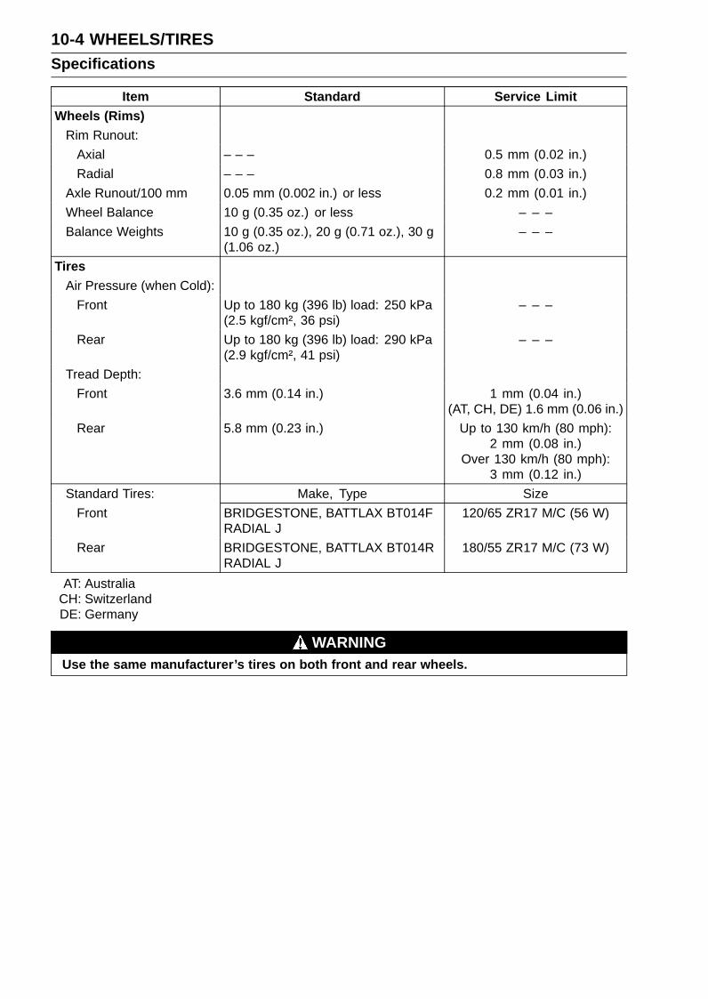
10-4 WHEELS/TIRESSpecifications
Item Standard Service LimitWheels (Rims)
Rim Runout:
Axial – – – 0.5 mm (0.02 in.)
Radial – – – 0.8 mm (0.03 in.)
Axle Runout/100 mm 0.05 mm (0.002 in.) or less 0.2 mm (0.01 in.)
Wheel Balance 10 g (0.35 oz.) or less – – –
Balance Weights 10 g (0.35 oz.), 20 g (0.71 oz.), 30 g(1.06 oz.)
– – –
TiresAir Pressure (when Cold):
Front Up to 180 kg (396 lb) load: 250 kPa(2.5 kgf/cm², 36 psi)
– – –
Rear Up to 180 kg (396 lb) load: 290 kPa(2.9 kgf/cm², 41 psi)
– – –
Tread Depth:
Front 3.6 mm (0.14 in.) 1 mm (0.04 in.)(AT, CH, DE) 1.6 mm (0.06 in.)
Rear 5.8 mm (0.23 in.) Up to 130 km/h (80 mph):2 mm (0.08 in.)
Over 130 km/h (80 mph):3 mm (0.12 in.)
Standard Tires: Make, Type Size
Front BRIDGESTONE, BATTLAX BT014FRADIAL J
120/65 ZR17 M/C (56 W)
Rear BRIDGESTONE, BATTLAX BT014RRADIAL J
180/55 ZR17 M/C (73 W)
AT: AustraliaCH: SwitzerlandDE: Germany
WARNINGUse the same manufacturer’s tires on both front and rear wheels.

WHEELS/TIRES 10-5Special Tools
Bearing Driver Set:57001-1129
Jack:57001-1238
Bearing Remover Head, 25 × 28:57001-1346
Bearing Remover Shaft, 13:57001-1377
Jack Attachment:57001-1608

10-6 WHEELS/TIRESWheels (Rims)
Front Wheel Removal•Remove:
Brake Caliper Mounting Bolts [A]Front Brake Calipers [B]
• Loosen:Axle Clamp Bolts [A] (Left Side)Axle Nut [B]Axle Clamp Bolts (Right Side)
•Remove the lower fairings (see Lower Fairing Removal inthe Frame chapter).
• Raise the front wheel off the ground.Special Tools - Jack: 57001-1238
Jack Attachment: 57001-1608
•Remove the axle nut and pull out the axle to the right anddrop the front wheel out of the forks.
CAUTION
Do not lay the wheel down on one of the discs. Thiscan damage or warp the disc. Place blocks un-der the wheel so that the disc does not touch theground.
Front Wheel Installation
NOTEThe direction of the wheel rotation [A] is shown by an
arrow [B] on the wheel spoke.
•Check the wheel rotation mark on the front wheel andinstall it.
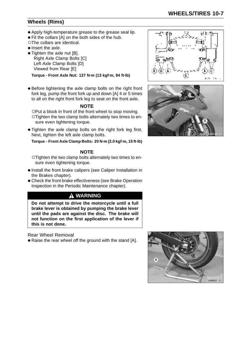
WHEELS/TIRES 10-7Wheels (Rims)
•Apply high-temperature grease to the grease seal lip.
• Fit the collars [A] on the both sides of the hub.The collars are identical.
• Insert the axle.
• Tighten the axle nut [B].Right Axle Clamp Bolts [C]Left Axle Clamp Bolts [D]Viewed from Rear [E]
Torque - Front Axle Nut: 127 N·m (13 kgf·m, 94 ft·lb)
•Before tightening the axle clamp bolts on the right frontfork leg, pump the front fork up and down [A] 4 or 5 timesto all on the right front fork leg to seat on the front axle.
NOTEPut a block in front of the front wheel to stop moving.Tighten the two clamp bolts alternately two times to en-
sure even tightening torque.
•Tighten the axle clamp bolts on the right fork leg first.Next, tighten the left axle clamp bolts.
Torque - Front Axle Clamp Bolts: 20 N·m (2.0 kgf·m, 15 ft·lb)
NOTETighten the two clamp bolts alternately two times to en-
sure even tightening torque.
• Install the front brake calipers (see Caliper Installation inthe Brakes chapter).
• Check the front brake effectiveness (see Brake OperationInspection in the Periodic Maintenance chapter).
WARNINGDo not attempt to drive the motorcycle until a fullbrake lever is obtained by pumping the brake leveruntil the pads are against the disc. The brake willnot function on the first application of the lever ifthis is not done.
Rear Wheel Removal•Raise the rear wheel off the ground with the stand [A].
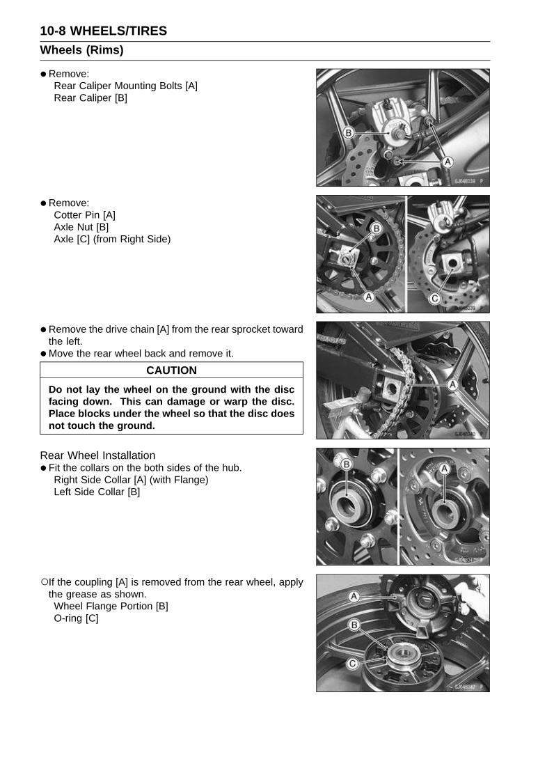
10-8 WHEELS/TIRESWheels (Rims)
•Remove:Rear Caliper Mounting Bolts [A]Rear Caliper [B]
•Remove:Cotter Pin [A]Axle Nut [B]Axle [C] (from Right Side)
•Remove the drive chain [A] from the rear sprocket towardthe left.
•Move the rear wheel back and remove it.
CAUTION
Do not lay the wheel on the ground with the discfacing down. This can damage or warp the disc.Place blocks under the wheel so that the disc doesnot touch the ground.
Rear Wheel Installation•Fit the collars on the both sides of the hub.
Right Side Collar [A] (with Flange)Left Side Collar [B]
If the coupling [A] is removed from the rear wheel, applythe grease as shown.Wheel Flange Portion [B]O-ring [C]
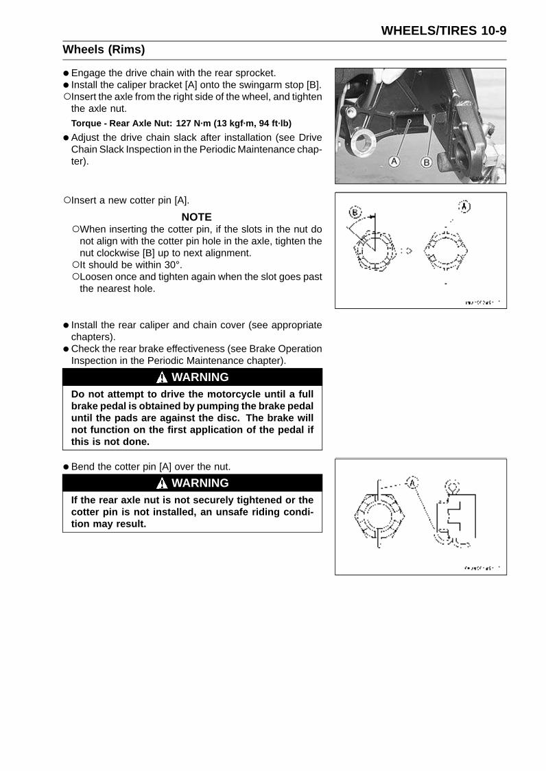
WHEELS/TIRES 10-9Wheels (Rims)
•Engage the drive chain with the rear sprocket.
• Install the caliper bracket [A] onto the swingarm stop [B].Insert the axle from the right side of the wheel, and tighten
the axle nut.Torque - Rear Axle Nut: 127 N·m (13 kgf·m, 94 ft·lb)
•Adjust the drive chain slack after installation (see DriveChain Slack Inspection in the Periodic Maintenance chap-ter).
Insert a new cotter pin [A].
NOTEWhen inserting the cotter pin, if the slots in the nut do
not align with the cotter pin hole in the axle, tighten thenut clockwise [B] up to next alignment.It should be within 30°.Loosen once and tighten again when the slot goes past
the nearest hole.
• Install the rear caliper and chain cover (see appropriatechapters).
• Check the rear brake effectiveness (see Brake OperationInspection in the Periodic Maintenance chapter).
WARNINGDo not attempt to drive the motorcycle until a fullbrake pedal is obtained by pumping the brake pedaluntil the pads are against the disc. The brake willnot function on the first application of the pedal ifthis is not done.
•Bend the cotter pin [A] over the nut.
WARNINGIf the rear axle nut is not securely tightened or thecotter pin is not installed, an unsafe riding condi-tion may result.
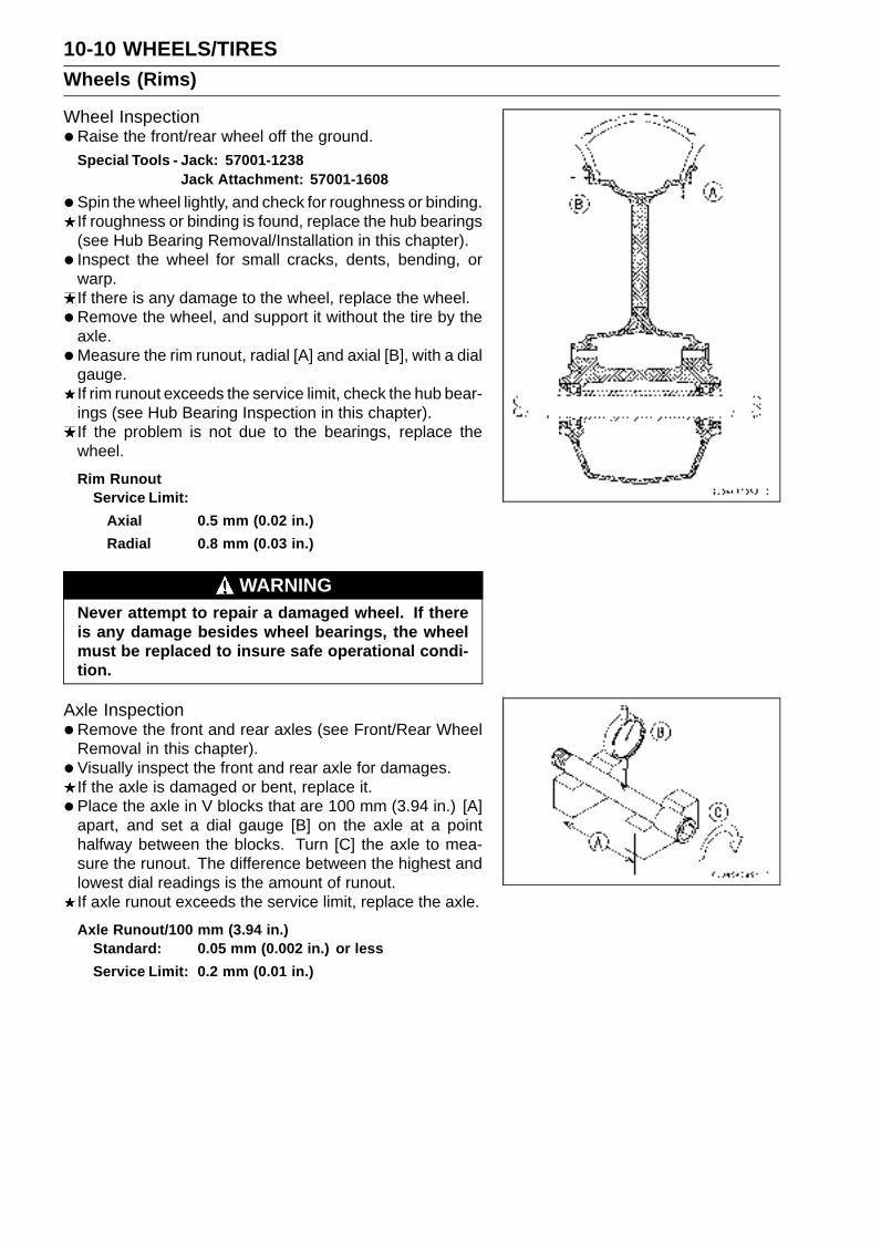
10-10 WHEELS/TIRESWheels (Rims)
Wheel Inspection•Raise the front/rear wheel off the ground.
Special Tools - Jack: 57001-1238Jack Attachment: 57001-1608
•Spin the wheel lightly, and check for roughness or binding.If roughness or binding is found, replace the hub bearings(see Hub Bearing Removal/Installation in this chapter).
• Inspect the wheel for small cracks, dents, bending, orwarp.If there is any damage to the wheel, replace the wheel.
• Remove the wheel, and support it without the tire by theaxle.
•Measure the rim runout, radial [A] and axial [B], with a dialgauge.If rim runout exceeds the service limit, check the hub bear-ings (see Hub Bearing Inspection in this chapter).If the problem is not due to the bearings, replace thewheel.
Rim RunoutService Limit:
Axial 0.5 mm (0.02 in.)
Radial 0.8 mm (0.03 in.)
WARNINGNever attempt to repair a damaged wheel. If thereis any damage besides wheel bearings, the wheelmust be replaced to insure safe operational condi-tion.
Axle Inspection•Remove the front and rear axles (see Front/Rear Wheel
Removal in this chapter).
• Visually inspect the front and rear axle for damages.If the axle is damaged or bent, replace it.
• Place the axle in V blocks that are 100 mm (3.94 in.) [A]apart, and set a dial gauge [B] on the axle at a pointhalfway between the blocks. Turn [C] the axle to mea-sure the runout. The difference between the highest andlowest dial readings is the amount of runout.If axle runout exceeds the service limit, replace the axle.
Axle Runout/100 mm (3.94 in.)Standard: 0.05 mm (0.002 in.) or less
Service Limit: 0.2 mm (0.01 in.)
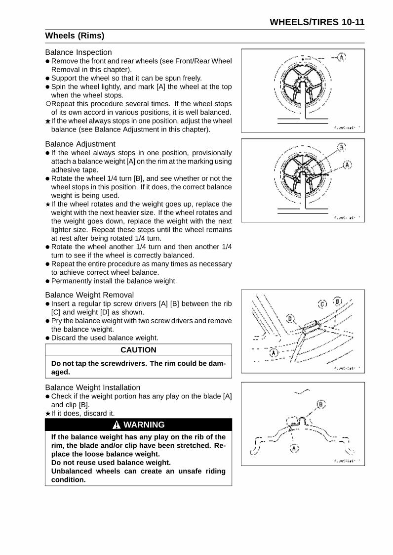
WHEELS/TIRES 10-11Wheels (Rims)
Balance Inspection•Remove the front and rear wheels (see Front/Rear Wheel
Removal in this chapter).
• Support the wheel so that it can be spun freely.
• Spin the wheel lightly, and mark [A] the wheel at the topwhen the wheel stops.Repeat this procedure several times. If the wheel stops
of its own accord in various positions, it is well balanced.If the wheel always stops in one position, adjust the wheelbalance (see Balance Adjustment in this chapter).
Balance Adjustment• If the wheel always stops in one position, provisionally
attach a balance weight [A] on the rim at the marking usingadhesive tape.
•Rotate the wheel 1/4 turn [B], and see whether or not thewheel stops in this position. If it does, the correct balanceweight is being used.If the wheel rotates and the weight goes up, replace theweight with the next heavier size. If the wheel rotates andthe weight goes down, replace the weight with the nextlighter size. Repeat these steps until the wheel remainsat rest after being rotated 1/4 turn.
•Rotate the wheel another 1/4 turn and then another 1/4turn to see if the wheel is correctly balanced.
•Repeat the entire procedure as many times as necessaryto achieve correct wheel balance.
• Permanently install the balance weight.
Balance Weight Removal• Insert a regular tip screw drivers [A] [B] between the rib
[C] and weight [D] as shown.
• Pry the balance weight with two screw drivers and removethe balance weight.
• Discard the used balance weight.
CAUTION
Do not tap the screwdrivers. The rim could be dam-aged.
Balance Weight Installation•Check if the weight portion has any play on the blade [A]
and clip [B].If it does, discard it.
WARNINGIf the balance weight has any play on the rib of therim, the blade and/or clip have been stretched. Re-place the loose balance weight.Do not reuse used balance weight.Unbalanced wheels can create an unsafe ridingcondition.

10-12 WHEELS/TIRESWheels (Rims)
Balance Weight
Part Number Weight
41075-0007 10 g (0.35 oz)
41075-0008 20 g (0.71 oz)
41075-0009 30 g (1.06 oz)
NOTEBalance weights are available from Kawasaki dealers
in 10, 20, and 30 gram (0.35 oz, 0.71 oz, and 1.06 oz)sizes. An imbalance of less than 10 grams (0.35 oz) willnot usually affect running stability.Do not use four or more balance weight (more than 90
gram, 3.2 oz). If the wheel requires an excess balanceweight, disassemble the wheel to find the cause.
•Slip the balance weight [A] on to the rib [B], by pushing orlightly hammering [C] the clip [D].Left Side [E]Right Side [F]
• Be sure to install the balance weight.Check that the blade [A] and clip [B] are fully seated on
the rim [C] and that the clip is hooked over the rib [D].Left Side [E]Right Side [F]
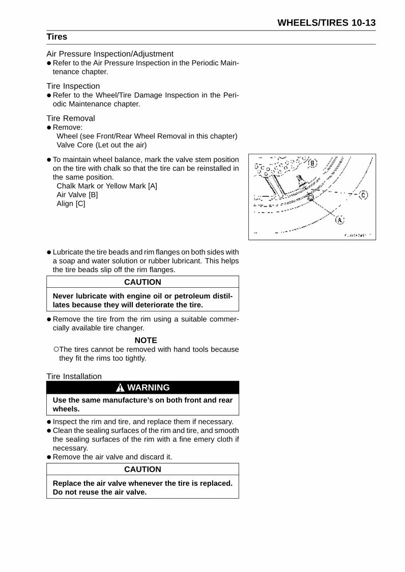
WHEELS/TIRES 10-13Tires
Air Pressure Inspection/Adjustment•Refer to the Air Pressure Inspection in the Periodic Main-
tenance chapter.
Tire Inspection•Refer to the Wheel/Tire Damage Inspection in the Peri-
odic Maintenance chapter.
Tire Removal•Remove:
Wheel (see Front/Rear Wheel Removal in this chapter)Valve Core (Let out the air)
• To maintain wheel balance, mark the valve stem positionon the tire with chalk so that the tire can be reinstalled inthe same position.Chalk Mark or Yellow Mark [A]Air Valve [B]Align [C]
• Lubricate the tire beads and rim flanges on both sides witha soap and water solution or rubber lubricant. This helpsthe tire beads slip off the rim flanges.
CAUTION
Never lubricate with engine oil or petroleum distil-lates because they will deteriorate the tire.
•Remove the tire from the rim using a suitable commer-cially available tire changer.
NOTEThe tires cannot be removed with hand tools because
they fit the rims too tightly.
Tire InstallationWARNING
Use the same manufacture’s on both front and rearwheels.
• Inspect the rim and tire, and replace them if necessary.
•Clean the sealing surfaces of the rim and tire, and smooththe sealing surfaces of the rim with a fine emery cloth ifnecessary.
•Remove the air valve and discard it.
CAUTION
Replace the air valve whenever the tire is replaced.Do not reuse the air valve.
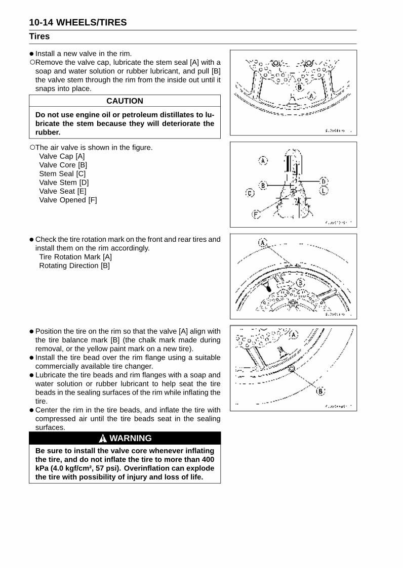
10-14 WHEELS/TIRESTires
• Install a new valve in the rim.Remove the valve cap, lubricate the stem seal [A] with a
soap and water solution or rubber lubricant, and pull [B]the valve stem through the rim from the inside out until itsnaps into place.
CAUTION
Do not use engine oil or petroleum distillates to lu-bricate the stem because they will deteriorate therubber.
The air valve is shown in the figure.Valve Cap [A]Valve Core [B]Stem Seal [C]Valve Stem [D]Valve Seat [E]Valve Opened [F]
•Check the tire rotation mark on the front and rear tires andinstall them on the rim accordingly.Tire Rotation Mark [A]Rotating Direction [B]
• Position the tire on the rim so that the valve [A] align withthe tire balance mark [B] (the chalk mark made duringremoval, or the yellow paint mark on a new tire).
• Install the tire bead over the rim flange using a suitablecommercially available tire changer.
• Lubricate the tire beads and rim flanges with a soap andwater solution or rubber lubricant to help seat the tirebeads in the sealing surfaces of the rim while inflating thetire.
•Center the rim in the tire beads, and inflate the tire withcompressed air until the tire beads seat in the sealingsurfaces.
WARNINGBe sure to install the valve core whenever inflatingthe tire, and do not inflate the tire to more than 400kPa (4.0 kgf/cm², 57 psi). Overinflation can explodethe tire with possibility of injury and loss of life.

WHEELS/TIRES 10-15Tires
•Check to see that the rim lines [A] on both sides of the tiresidewalls are parallel with the rim flanges.If the rim flanges and tire sidewall rim lines are not parallel,remove the valve core.
• Lubricate the rim flanges and tire beads.
• Install the valve core and inflate the tire again.
• After the tire beads seat in the rim flanges, check for airleakage.Inflate the tire slightly above standard inflation.Use a soap and water solution or submerge the tire, and
check for bubbles that would indicate leakage.
• Adjust the air pressure to the specified pressure (see AirPressure Inspection in the Periodic Maintenance chap-ter).
• Install the air valve cap.
• Adjust the wheel balance (see Balance Adjustment in thischapter).
Tire RepairCurrently two types of repair for tubeless tires have come
into wide use. One type is called a temporary (external) re-pair which can be carried out without removing the tire fromthe rim, and the other type is called permanent (internal)repair which requires tire removal. It is generally under-stood that higher running durability is obtained by perma-nent (internal) repairs than by temporary (external) ones.Also, permanent (internal) repairs have the advantage ofpermitting a thorough examination for secondary damagenot visible from external inspection of the tire. For thesereasons, Kawasaki does not recommend temporary (exter-nal) repair. Only appropriate permanent (internal) repairsare recommended. Repair methods may vary slightly frommake to make. Follow the repair methods indicated by themanufacturer of the repair tools and materials so that saferesults can be obtained.

10-16 WHEELS/TIRESHub Bearing
Hub Bearing Removal•Remove the wheel (see Front/Rear Wheel Removal in
this chapter), and take out the following.CollarsCoupling (Out of rear hub)Grease Seals
•Use the bearing remover to remove the hub bearing [A].
CAUTION
Do not lay the wheel on the ground with the discfacing down. This can damage or warp the disc.Place blocks under the wheel so that the disc doesnot touch the ground.
Special Tools - Bearing Remover Head, 25 × 28 [C]:57001-1346
Bearing Remover Shaft, 13 [B]: 57001-1377
Hub Bearing Installation•Before installing the hub bearings, blow any dirt or foreign
particles out of the hub with compressed air to preventcontamination of the bearings.
•Replace the bearings with new ones.
• Install the bearings by using the bearing driver set whichdoes not contact the bearing inner race.
• Press in each right the bearing [A] until they are bottomed.Special Tool - Bearing Driver Set [B]: 57001-1129
•Replace the grease seals with new ones.
• Press in the grease seals [A] so that the seal surface isflush [B] with the end of the hole.Apply high-temperature grease to the grease seal lips.
Special Tool - Bearing Driver Set [C]: 57001-1129
Hub Bearing InspectionSince the hub bearings are made to extremely close tol-
erances, the clearance can not normally be measured.
NOTEDo not remove any bearings for inspection. If any bear-
ings are removed, they will need to be replaced withnew ones.
•Turn each bearing in the hub back and forth [A] whilechecking for plays, roughness, or binding.If bearing play, roughness, or binding is found, replacethe bearing.
• Examine the bearing seal [B] for tears or leakage.If the seal is torn or is leaking, replace the bearing.

WHEELS/TIRES 10-17Hub Bearing
Hub Bearing Lubrication
NOTESince the hub bearings are packed with grease and
sealed, lubrication is not required.

FINAL DRIVE 11-1
11
Final Drive
Table of Contents
Exploded View ....................................................................................................................... 11-2Specifications ........................................................................................................................ 11-4Special Tools .......................................................................................................................... 11-5Drive Chain............................................................................................................................. 11-6
Drive Chain Slack Inspection ............................................................................................ 11-6Drive Chain Slack Adjustment .......................................................................................... 11-6Wheel Alignment Inspection/Adjustment .......................................................................... 11-6Drive Chain Wear Inspection ............................................................................................ 11-6Drive Chain Lubrication..................................................................................................... 11-6Drive Chain Removal ........................................................................................................ 11-6Drive Chain Installation ..................................................................................................... 11-7
Sprocket, Coupling ................................................................................................................. 11-10Engine Sprocket Removal ................................................................................................ 11-10Engine Sprocket Installation ............................................................................................. 11-10Rear Sprocket Removal.................................................................................................... 11-11Rear Sprocket Installation................................................................................................. 11-11Coupling Installation.......................................................................................................... 11-11Coupling Bearing Removal ............................................................................................... 11-12Coupling Bearing Installation ............................................................................................ 11-12Coupling Bearing Inspection ............................................................................................. 11-13Coupling Bearing Lubrication............................................................................................ 11-13Coupling Damper Inspection............................................................................................. 11-13Sprocket Wear Inspection................................................................................................. 11-13Rear Sprocket Warp Inspection ........................................................................................ 11-14

11-2 FINAL DRIVEExploded View
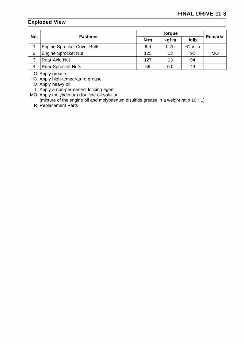
FINAL DRIVE 11-3Exploded View
TorqueNo. Fastener
N·m kgf·m ft·lbRemarks
1 Engine Sprocket Cover Bolts 6.9 0.70 61 in·lb
2 Engine Sprocket Nut 125 13 92 MO
3 Rear Axle Nut 127 13 94
4 Rear Sprocket Nuts 59 6.0 43
G: Apply grease.HG: Apply high-temperature grease.HO: Apply heavy oil.
L: Apply a non-permanent locking agent.MO: Apply molybdenum disulfide oil solution.
(mixture of the engine oil and molybdenum disulfide grease in a weight ratio 10 : 1)R: Replacement Parts

11-4 FINAL DRIVESpecifications
Item Standard Service LimitDrive Chain
Standard Chain:
Make ENUMA – – –
Type EK520MVXL – – –
Link 110 links – – –
SprocketsRear Sprocket Warp 0.4 mm (0.016 in.) or less 0.5 mm (0.02 in.)
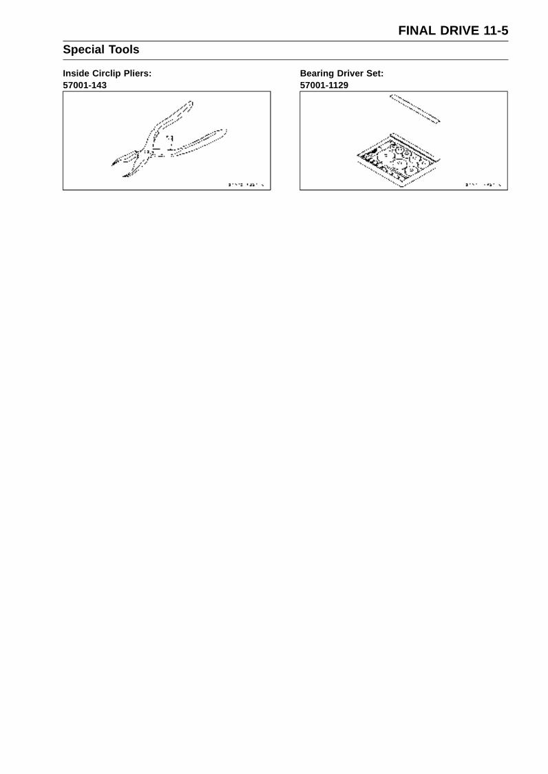
FINAL DRIVE 11-5Special Tools
Inside Circlip Pliers:57001-143
Bearing Driver Set:57001-1129
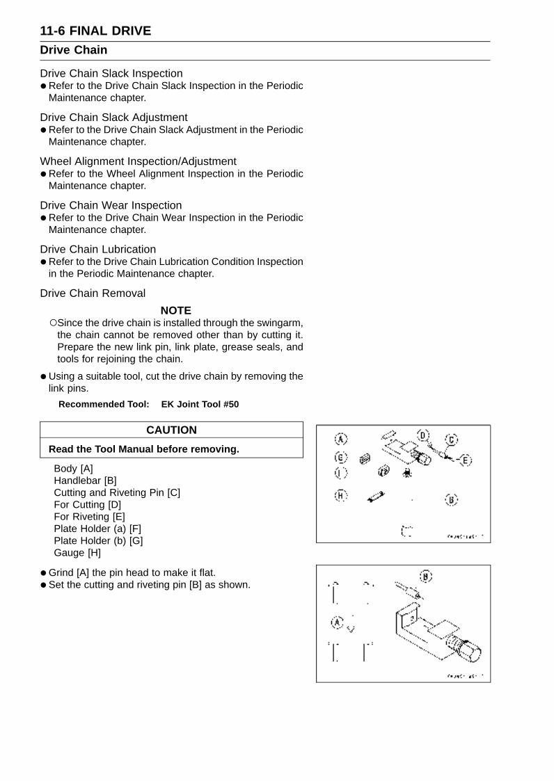
11-6 FINAL DRIVEDrive Chain
Drive Chain Slack Inspection•Refer to the Drive Chain Slack Inspection in the Periodic
Maintenance chapter.
Drive Chain Slack Adjustment•Refer to the Drive Chain Slack Adjustment in the Periodic
Maintenance chapter.
Wheel Alignment Inspection/Adjustment•Refer to the Wheel Alignment Inspection in the Periodic
Maintenance chapter.
Drive Chain Wear Inspection•Refer to the Drive Chain Wear Inspection in the Periodic
Maintenance chapter.
Drive Chain Lubrication•Refer to the Drive Chain Lubrication Condition Inspection
in the Periodic Maintenance chapter.
Drive Chain Removal
NOTESince the drive chain is installed through the swingarm,
the chain cannot be removed other than by cutting it.Prepare the new link pin, link plate, grease seals, andtools for rejoining the chain.
•Using a suitable tool, cut the drive chain by removing thelink pins.
Recommended Tool: EK Joint Tool #50
CAUTION
Read the Tool Manual before removing.
Body [A]Handlebar [B]Cutting and Riveting Pin [C]For Cutting [D]For Riveting [E]Plate Holder (a) [F]Plate Holder (b) [G]Gauge [H]
•Grind [A] the pin head to make it flat.
• Set the cutting and riveting pin [B] as shown.

FINAL DRIVE 11-7Drive Chain
•Screw the pin holder until it touches chain pin.
• Be sure that the cutting pin hits center of chain pin.
• Screw the handlebar [A] into body.
• Turn the pin holder with wrench [B] clockwise to extractchain pin.
Drive Chain Installation•Engage the new drive chain to the old drive chain and pull
the end of the old drive chain until they are changing theposition.
•Remove the old drive chain from the new drive chain.
• Apply grease to the link pins [A] and grease seals [B] [C].
• Engage the drive chain on the rear sprocket through theswingarm.
• Insert the link pins in the drive chain ends.
• Install the grease seals [C].
• Install the link plate so that the mark [D] faces out.
• Push the link plate by hand or plier to fix it.
• In case of grease seal chain, be sure to set the greaseseals correctly.
• Set the plate holder (a) [A] and plate holder (b) [B] on thebody.

11-8 FINAL DRIVEDrive Chain
•Fit the plate holder (a) to link plate.
• Turn the pin holder by hand until plate holder (b) touchesthe other link plate.
• Turn the pin holder by wrench clockwise until two pins oflink come into groove of plate holder (a).
• Take off the plate holder (a).
• Set the plate holder (b) [A] and cutting and riveting pin [B]as shown.
• Turn the pin holder until riveting pin touches link pin.
• Turn the wrench clockwise until tip of riveting pin hits oflink pin.
•Rivet it.
• Same work for the other link pin.

FINAL DRIVE 11-9Drive Chain
•After staking, check the staked area of the link pin forcracks.
•Measure the outside diameter [A] of the link pin and linkplates width [B].
Link Pin Outside DiameterStandard: 5.7 ∼ 6.0 mm (0.22 ∼ 0.24 in.)
Link Plates Outside WidthStandard: 17.25 ∼ 17.45 mm (0.679 ∼ 0.687 in.)
If the reading exceeds the specified length, cut and rejointhe chain again.
•Check:Movement of the Rollers
• Adjust the drive chain slack after installing the chain (seeDrive Chain Slack Adjustment in the Periodic Mainte-nance chapter).
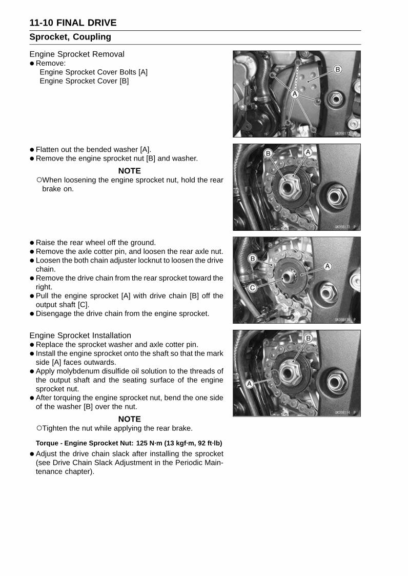
11-10 FINAL DRIVESprocket, Coupling
Engine Sprocket Removal•Remove:
Engine Sprocket Cover Bolts [A]Engine Sprocket Cover [B]
• Flatten out the bended washer [A].
• Remove the engine sprocket nut [B] and washer.
NOTEWhen loosening the engine sprocket nut, hold the rear
brake on.
•Raise the rear wheel off the ground.
•Remove the axle cotter pin, and loosen the rear axle nut.
• Loosen the both chain adjuster locknut to loosen the drivechain.
•Remove the drive chain from the rear sprocket toward theright.
• Pull the engine sprocket [A] with drive chain [B] off theoutput shaft [C].
• Disengage the drive chain from the engine sprocket.
Engine Sprocket Installation•Replace the sprocket washer and axle cotter pin.
• Install the engine sprocket onto the shaft so that the markside [A] faces outwards.
• Apply molybdenum disulfide oil solution to the threads ofthe output shaft and the seating surface of the enginesprocket nut.
• After torquing the engine sprocket nut, bend the one sideof the washer [B] over the nut.
NOTETighten the nut while applying the rear brake.
Torque - Engine Sprocket Nut: 125 N·m (13 kgf·m, 92 ft·lb)
•Adjust the drive chain slack after installing the sprocket(see Drive Chain Slack Adjustment in the Periodic Main-tenance chapter).
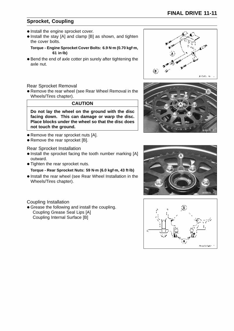
FINAL DRIVE 11-11Sprocket, Coupling
• Install the engine sprocket cover.
• Install the stay [A] and clamp [B] as shown, and tightenthe cover bolts.
Torque - Engine Sprocket Cover Bolts: 6.9 N·m (0.70 kgf·m,61 in·lb)
•Bend the end of axle cotter pin surely after tightening theaxle nut.
Rear Sprocket Removal•Remove the rear wheel (see Rear Wheel Removal in the
Wheels/Tires chapter).
CAUTION
Do not lay the wheel on the ground with the discfacing down. This can damage or warp the disc.Place blocks under the wheel so that the disc doesnot touch the ground.
•Remove the rear sprocket nuts [A].
• Remove the rear sprocket [B].
Rear Sprocket Installation• Install the sprocket facing the tooth number marking [A]
outward.
• Tighten the rear sprocket nuts.
Torque - Rear Sprocket Nuts: 59 N·m (6.0 kgf·m, 43 ft·lb)
• Install the rear wheel (see Rear Wheel Installation in theWheels/Tires chapter).
Coupling Installation•Grease the following and install the coupling.
Coupling Grease Seal Lips [A]Coupling Internal Surface [B]
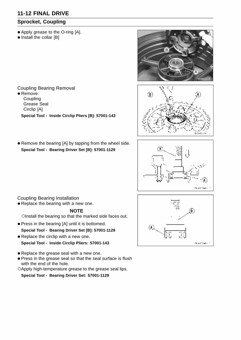
11-12 FINAL DRIVESprocket, Coupling
•Apply grease to the O-ring [A].
• Install the collar [B]
Coupling Bearing Removal•Remove:
CouplingGrease SealCirclip [A]
Special Tool - Inside Circlip Pliers [B]: 57001-143
•Remove the bearing [A] by tapping from the wheel side.Special Tool - Bearing Driver Set [B]: 57001-1129
Coupling Bearing Installation•Replace the bearing with a new one.
NOTEInstall the bearing so that the marked side faces out.
•Press in the bearing [A] until it is bottomed.Special Tool - Bearing Driver Set [B]: 57001-1129
•Replace the circlip with a new one.Special Tool - Inside Circlip Pliers: 57001-143
•Replace the grease seal with a new one.
• Press in the grease seal so that the seal surface is flushwith the end of the hole.Apply high-temperature grease to the grease seal lips.
Special Tool - Bearing Driver Set: 57001-1129
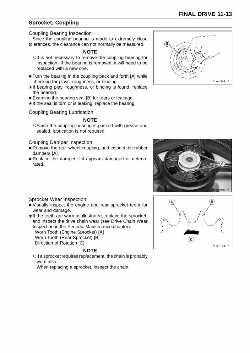
FINAL DRIVE 11-13Sprocket, Coupling
Coupling Bearing InspectionSince the coupling bearing is made to extremely close
tolerances, the clearance can not normally be measured.
NOTEIt is not necessary to remove the coupling bearing for
inspection. If the bearing is removed, it will need to bereplaced with a new one.
•Turn the bearing in the coupling back and forth [A] whilechecking for plays, roughness, or binding.If bearing play, roughness, or binding is found, replacethe bearing.
• Examine the bearing seal [B] for tears or leakage.If the seal is torn or is leaking, replace the bearing.
Coupling Bearing Lubrication
NOTESince the coupling bearing is packed with grease and
sealed, lubrication is not required.
Coupling Damper Inspection•Remove the rear wheel coupling, and inspect the rubber
dampers [A].
• Replace the damper if it appears damaged or deterio-rated.
Sprocket Wear Inspection•Visually inspect the engine and rear sprocket teeth for
wear and damage.If the teeth are worn as illustrated, replace the sprocket,and inspect the drive chain wear (see Drive Chain WearInspection in the Periodic Maintenance chapter).Worn Tooth (Engine Sprocket) [A]Worn Tooth (Rear Sprocket) [B]Direction of Rotation [C]
NOTEIf a sprocket requires replacement, the chain is probably
worn also.When replacing a sprocket, inspect the chain.

11-14 FINAL DRIVESprocket, Coupling
Rear Sprocket Warp Inspection•Raise the rear wheel off the ground so that it will turn
freely.
• Set a dial gauge [A] against the rear sprocket [B] near theteeth as shown, and rotate [C] the rear wheel to measurethe sprocket runout (warp). The difference between thehighest and lowest dial gauge readings is the amount ofrunout (warp).If the runout exceeds the service limit, replace the rearsprocket.
Rear Sprocket WarpStandard: 0.4 mm (0.016 in.) or less
Service Limit: 0.5 mm (0.02 in.)

BRAKES 12-1
12
Brakes
Table of Contents
Exploded View .................................. 12-2Specifications ................................... 12-6Special Tools ..................................... 12-7Brake Lever, Brake Pedal.................. 12-8
Brake Lever Position Adjustment. 12-8Brake Pedal Position Inspection . 12-8Brake Pedal Position Adjustment 12-8Brake Pedal Removal .................. 12-8Brake Pedal Installation ............... 12-9
Calipers ............................................. 12-10Front Caliper Removal ................. 12-10Rear Caliper Removal.................. 12-10Caliper Installation ....................... 12-10Front Caliper Disassembly........... 12-11Front Caliper Assembly................ 12-11Rear Caliper Disassembly ........... 12-11Rear Caliper Assembly ................ 12-11Caliper Fluid Seal Damage.......... 12-11Rear Caliper Dust Boot and
Friction Boot Damage ............... 12-12Caliper Piston and Cylinder
Damage..................................... 12-12Rear Caliper Holder Shaft Wear .. 12-12
Brake Pads........................................ 12-13Front Brake Pad Removal............ 12-13Front Brake Pad Installation......... 12-13Rear Brake Pad Removal ........... 12-14
Rear Brake Pad Installation ......... 12-14Brake Pad Wear Inspection ......... 12-14
Master Cylinder ................................. 12-15Front Master Cylinder Removal ... 12-15Front Master Cylinder Installation 12-15Rear Master Cylinder Removal.... 12-16Rear Master Cylinder Installation. 12-16Front Master Cylinder
Disassembly.............................. 12-16Rear Master Cylinder
Disassembly.............................. 12-16Master Cylinder Assembly ........... 12-16Master Cylinder Inspection (Visual
Inspection)................................. 12-16Brake Disc ......................................... 12-18
Brake Disc Removal .................... 12-18Brake Disc Installation ................. 12-18Brake Disc Wear .......................... 12-18Brake Disc Warp .......................... 12-18
Brake Fluid ........................................ 12-19Brake Fluid Level Inspection........ 12-19Brake Fluid Change ..................... 12-19Brake Line Bleeding..................... 12-19
Brake Hose........................................ 12-23Brake Hose Removal/Installation. 12-23Brake Hose Inspection................. 12-23

12-2 BRAKESExploded View
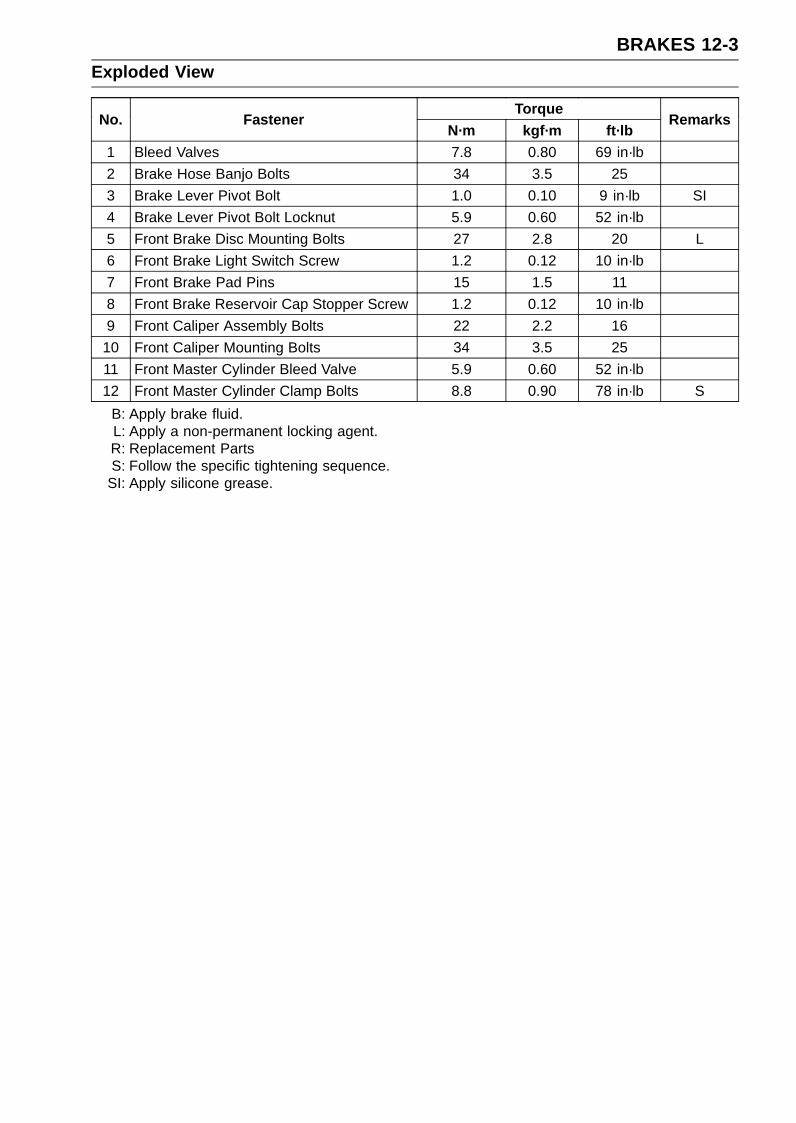
BRAKES 12-3Exploded View
TorqueNo. Fastener
N·m kgf·m ft·lbRemarks
1 Bleed Valves 7.8 0.80 69 in·lb
2 Brake Hose Banjo Bolts 34 3.5 25
3 Brake Lever Pivot Bolt 1.0 0.10 9 in·lb SI
4 Brake Lever Pivot Bolt Locknut 5.9 0.60 52 in·lb
5 Front Brake Disc Mounting Bolts 27 2.8 20 L
6 Front Brake Light Switch Screw 1.2 0.12 10 in·lb
7 Front Brake Pad Pins 15 1.5 11
8 Front Brake Reservoir Cap Stopper Screw 1.2 0.12 10 in·lb
9 Front Caliper Assembly Bolts 22 2.2 16
10 Front Caliper Mounting Bolts 34 3.5 25
11 Front Master Cylinder Bleed Valve 5.9 0.60 52 in·lb
12 Front Master Cylinder Clamp Bolts 8.8 0.90 78 in·lb S
B: Apply brake fluid.L: Apply a non-permanent locking agent.R: Replacement PartsS: Follow the specific tightening sequence.
SI: Apply silicone grease.
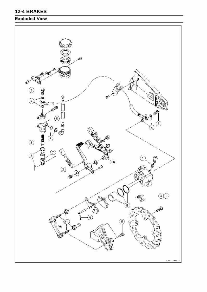
12-4 BRAKESExploded View
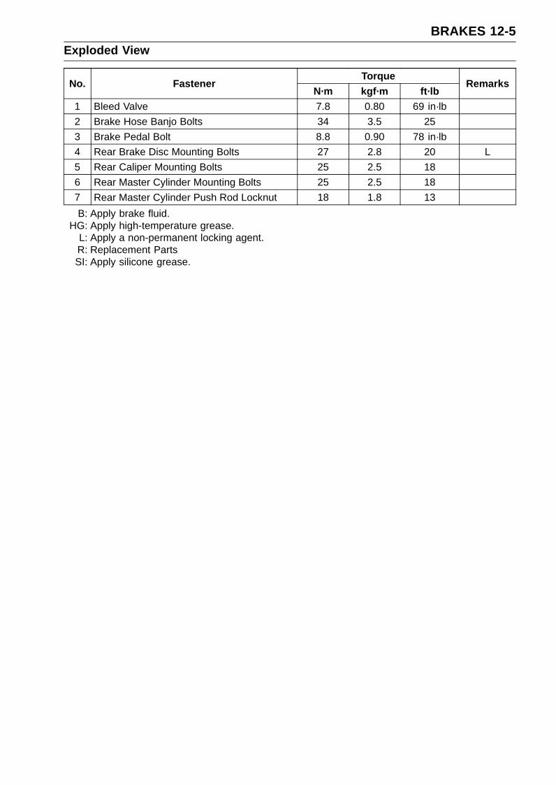
BRAKES 12-5Exploded View
TorqueNo. Fastener
N·m kgf·m ft·lbRemarks
1 Bleed Valve 7.8 0.80 69 in·lb
2 Brake Hose Banjo Bolts 34 3.5 25
3 Brake Pedal Bolt 8.8 0.90 78 in·lb
4 Rear Brake Disc Mounting Bolts 27 2.8 20 L
5 Rear Caliper Mounting Bolts 25 2.5 18
6 Rear Master Cylinder Mounting Bolts 25 2.5 18
7 Rear Master Cylinder Push Rod Locknut 18 1.8 13
B: Apply brake fluid.HG: Apply high-temperature grease.
L: Apply a non-permanent locking agent.R: Replacement PartsSI: Apply silicone grease.

12-6 BRAKESSpecifications
Item Standard Service LimitBrake Lever, Brake Pedal
Brake Lever Position 6-way adjustable (to suit rider) – – –
Brake Lever Free Play Non-adjustable – – –
Pedal Free Play Non-adjustable – – –
Pedal Position About 60 mm (2.4 in.) below footpeg top – – –
Brake DiscsThickness:
Front 5.3 ∼ 5.7 mm (0.21 ∼ 0.22 in.) 5.0 mm (0.20 in.)
Rear 4.8 ∼ 5.2 mm (0.19 ∼ 0.20 in.) 4.5 mm (0.18 in.)
Runout 0.15 mm (0.006 in.) or less 0.3 mm (0.01 in.)
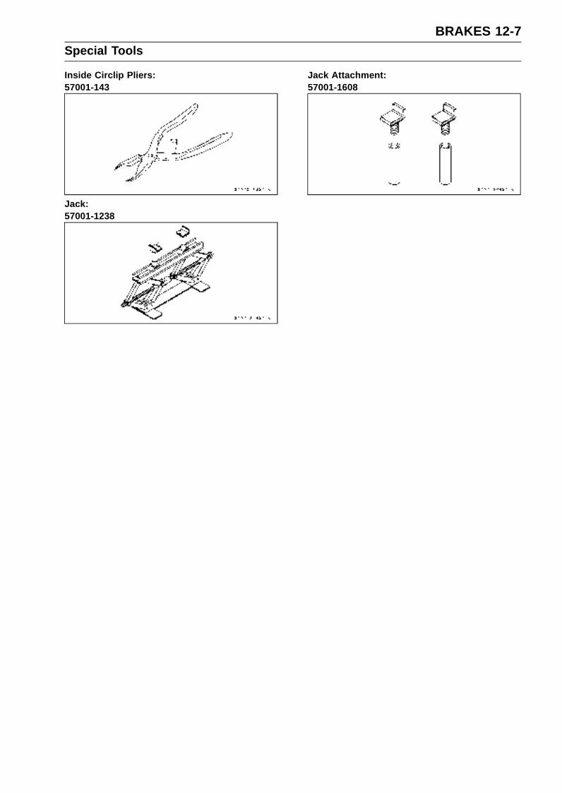
BRAKES 12-7Special Tools
Inside Circlip Pliers:57001-143
Jack:57001-1238
Jack Attachment:57001-1608
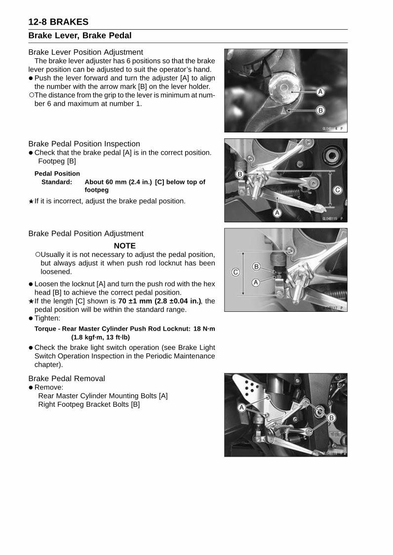
12-8 BRAKESBrake Lever, Brake Pedal
Brake Lever Position AdjustmentThe brake lever adjuster has 6 positions so that the brake
lever position can be adjusted to suit the operator’s hand.
• Push the lever forward and turn the adjuster [A] to alignthe number with the arrow mark [B] on the lever holder.The distance from the grip to the lever is minimum at num-
ber 6 and maximum at number 1.
Brake Pedal Position Inspection•Check that the brake pedal [A] is in the correct position.
Footpeg [B]
Pedal PositionStandard: About 60 mm (2.4 in.) [C] below top of
footpeg
If it is incorrect, adjust the brake pedal position.
Brake Pedal Position Adjustment
NOTEUsually it is not necessary to adjust the pedal position,
but always adjust it when push rod locknut has beenloosened.
• Loosen the locknut [A] and turn the push rod with the hexhead [B] to achieve the correct pedal position.If the length [C] shown is 70 ±1 mm (2.8 ±0.04 in.), thepedal position will be within the standard range.
• Tighten:Torque - Rear Master Cylinder Push Rod Locknut: 18 N·m
(1.8 kgf·m, 13 ft·lb)
•Check the brake light switch operation (see Brake LightSwitch Operation Inspection in the Periodic Maintenancechapter).
Brake Pedal Removal•Remove:
Rear Master Cylinder Mounting Bolts [A]Right Footpeg Bracket Bolts [B]
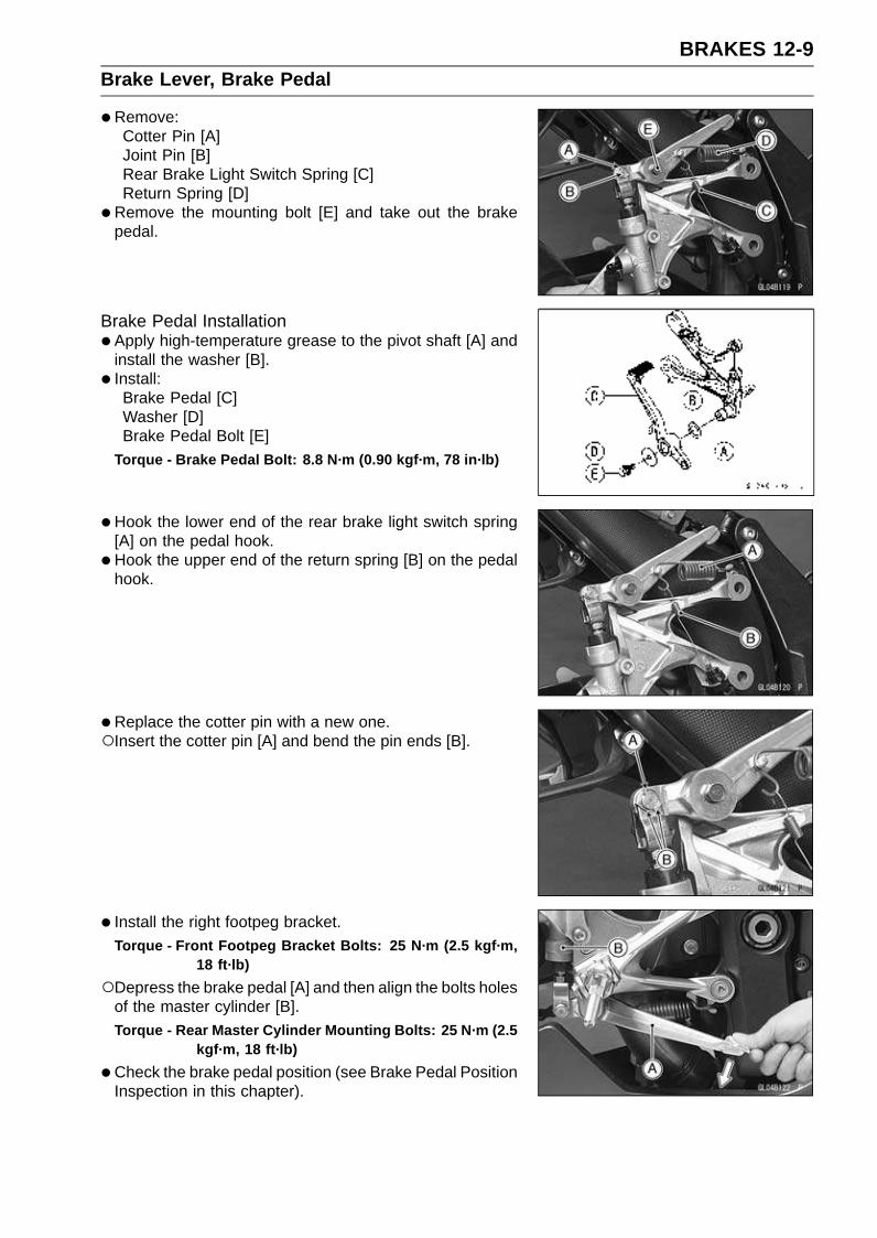
BRAKES 12-9Brake Lever, Brake Pedal
•Remove:Cotter Pin [A]Joint Pin [B]Rear Brake Light Switch Spring [C]Return Spring [D]
•Remove the mounting bolt [E] and take out the brakepedal.
Brake Pedal Installation•Apply high-temperature grease to the pivot shaft [A] and
install the washer [B].
• Install:Brake Pedal [C]Washer [D]Brake Pedal Bolt [E]
Torque - Brake Pedal Bolt: 8.8 N·m (0.90 kgf·m, 78 in·lb)
•Hook the lower end of the rear brake light switch spring[A] on the pedal hook.
•Hook the upper end of the return spring [B] on the pedalhook.
•Replace the cotter pin with a new one.Insert the cotter pin [A] and bend the pin ends [B].
• Install the right footpeg bracket.Torque - Front Footpeg Bracket Bolts: 25 N·m (2.5 kgf·m,
18 ft·lb)
Depress the brake pedal [A] and then align the bolts holesof the master cylinder [B].Torque - Rear Master Cylinder Mounting Bolts: 25 N·m (2.5
kgf·m, 18 ft·lb)
•Check the brake pedal position (see Brake Pedal PositionInspection in this chapter).
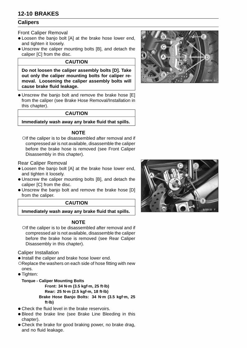
12-10 BRAKESCalipers
Front Caliper Removal• Loosen the banjo bolt [A] at the brake hose lower end,
and tighten it loosely.
•Unscrew the caliper mounting bolts [B], and detach thecaliper [C] from the disc.
CAUTION
Do not loosen the caliper assembly bolts [D]. Takeout only the caliper mounting bolts for caliper re-moval. Loosening the caliper assembly bolts willcause brake fluid leakage.
•Unscrew the banjo bolt and remove the brake hose [E]from the caliper (see Brake Hose Removal/Installation inthis chapter).
CAUTION
Immediately wash away any brake fluid that spills.
NOTEIf the caliper is to be disassembled after removal and if
compressed air is not available, disassemble the caliperbefore the brake hose is removed (see Front CaliperDisassembly in this chapter).
Rear Caliper Removal• Loosen the banjo bolt [A] at the brake hose lower end,
and tighten it loosely.
•Unscrew the caliper mounting bolts [B], and detach thecaliper [C] from the disc.
•Unscrew the banjo bolt and remove the brake hose [D]from the caliper.
CAUTION
Immediately wash away any brake fluid that spills.
NOTEIf the caliper is to be disassembled after removal and if
compressed air is not available, disassemble the caliperbefore the brake hose is removed (see Rear CaliperDisassembly in this chapter).
Caliper Installation• Install the caliper and brake hose lower end.Replace the washers on each side of hose fitting with new
ones.
• Tighten:Torque - Caliper Mounting Bolts
Front: 34 N·m (3.5 kgf·m, 25 ft·lb)Rear: 25 N·m (2.5 kgf·m, 18 ft·lb)
Brake Hose Banjo Bolts: 34 N·m (3.5 kgf·m, 25ft·lb)
•Check the fluid level in the brake reservoirs.
• Bleed the brake line (see Brake Line Bleeding in thischapter).
• Check the brake for good braking power, no brake drag,and no fluid leakage.

BRAKES 12-11Calipers
WARNINGDo not attempt to drive the motorcycle until a fullbrake lever or pedal is obtained by pumping thebrake lever or pedal until the pads are against thedisc. The brakes will not function on the first appli-cation of the lever or pedal if this is not done.
Front Caliper Disassembly•Refer to the Caliper Rubber Parts Replacement in the Pe-
riodic Maintenance chapter.
Front Caliper Assembly•Refer to the Caliper Rubber Parts Replacement in the Pe-
riodic Maintenance chapter.
Rear Caliper Disassembly•Refer to the Caliper Rubber Parts Replacement in the Pe-
riodic Maintenance chapter.
Rear Caliper Assembly•Refer to the Caliper Rubber Parts Replacement in the Pe-
riodic Maintenance chapter.
Caliper Fluid Seal DamageThe fluid seal (piston seal) [A] is placed around the pis-
ton to maintain clearance between the pad and the disc. Ifthe seal is in a poor condition, it could lead the pad to wearexcessively or the brake to drag, which may cause the tem-perature of the discs or the brake fluid to increase.
•Replace the fluid seal if it exhibits any of the conditionslisted below.Brake fluid leakage around the pad.Brakes overheat.Considerable difference in inner and outer pad wear.Seal and piston are stuck together.
If the fluid seal is replaced, replace the dust seal [B] aswell. Also, replace all seals every other time the pads arechanged.
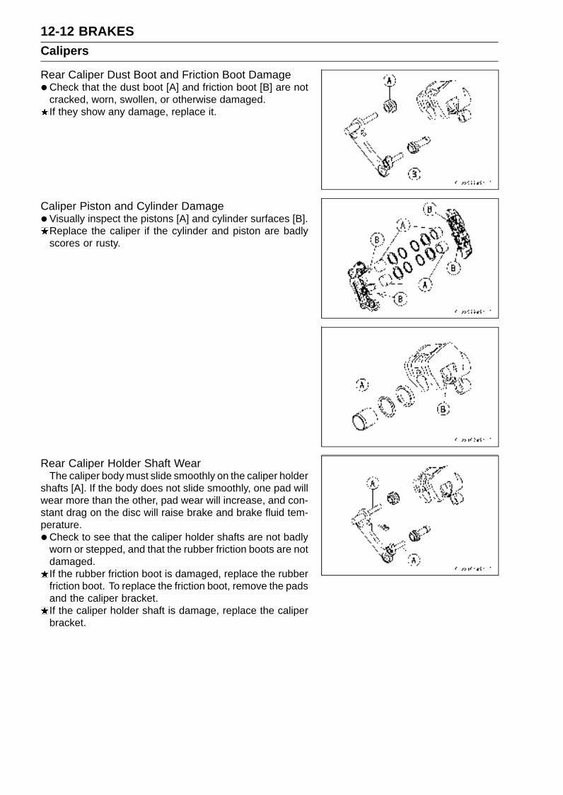
12-12 BRAKESCalipers
Rear Caliper Dust Boot and Friction Boot Damage•Check that the dust boot [A] and friction boot [B] are not
cracked, worn, swollen, or otherwise damaged.If they show any damage, replace it.
Caliper Piston and Cylinder Damage•Visually inspect the pistons [A] and cylinder surfaces [B].
Replace the caliper if the cylinder and piston are badlyscores or rusty.
Rear Caliper Holder Shaft WearThe caliper body must slide smoothly on the caliper holder
shafts [A]. If the body does not slide smoothly, one pad willwear more than the other, pad wear will increase, and con-stant drag on the disc will raise brake and brake fluid tem-perature.
•Check to see that the caliper holder shafts are not badlyworn or stepped, and that the rubber friction boots are notdamaged.If the rubber friction boot is damaged, replace the rubberfriction boot. To replace the friction boot, remove the padsand the caliper bracket.If the caliper holder shaft is damage, replace the caliperbracket.
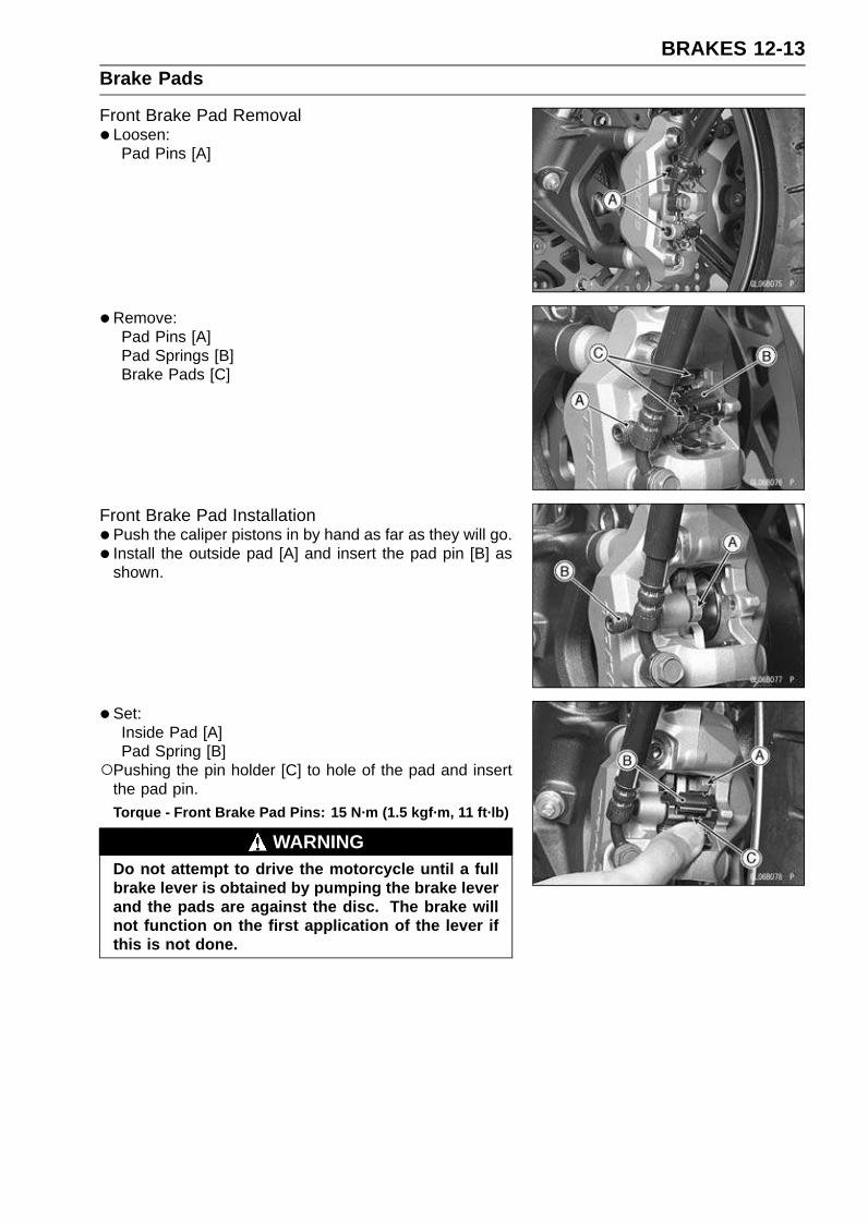
BRAKES 12-13Brake Pads
Front Brake Pad Removal• Loosen:
Pad Pins [A]
•Remove:Pad Pins [A]Pad Springs [B]Brake Pads [C]
Front Brake Pad Installation•Push the caliper pistons in by hand as far as they will go.
• Install the outside pad [A] and insert the pad pin [B] asshown.
• Set:Inside Pad [A]Pad Spring [B]
Pushing the pin holder [C] to hole of the pad and insertthe pad pin.Torque - Front Brake Pad Pins: 15 N·m (1.5 kgf·m, 11 ft·lb)
WARNINGDo not attempt to drive the motorcycle until a fullbrake lever is obtained by pumping the brake leverand the pads are against the disc. The brake willnot function on the first application of the lever ifthis is not done.
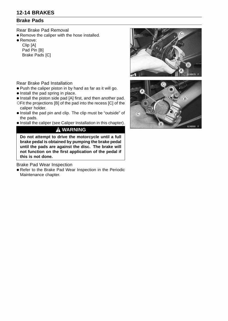
12-14 BRAKESBrake Pads
Rear Brake Pad Removal•Remove the caliper with the hose installed.
•Remove:Clip [A]Pad Pin [B]Brake Pads [C]
Rear Brake Pad Installation•Push the caliper piston in by hand as far as it will go.
• Install the pad spring in place.
• Install the piston side pad [A] first, and then another pad.Fit the projections [B] of the pad into the recess [C] of the
caliper holder.
• Install the pad pin and clip. The clip must be “outside” ofthe pads.
• Install the caliper (see Caliper Installation in this chapter).
WARNINGDo not attempt to drive the motorcycle until a fullbrake pedal is obtained by pumping the brake pedaluntil the pads are against the disc. The brake willnot function on the first application of the pedal ifthis is not done.
Brake Pad Wear Inspection•Refer to the Brake Pad Wear Inspection in the Periodic
Maintenance chapter.
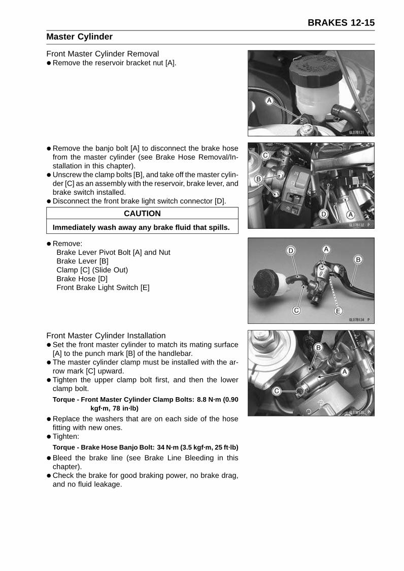
BRAKES 12-15Master Cylinder
Front Master Cylinder Removal•Remove the reservoir bracket nut [A].
• Remove the banjo bolt [A] to disconnect the brake hosefrom the master cylinder (see Brake Hose Removal/In-stallation in this chapter).
• Unscrew the clamp bolts [B], and take off the master cylin-der [C] as an assembly with the reservoir, brake lever, andbrake switch installed.
•Disconnect the front brake light switch connector [D].
CAUTION
Immediately wash away any brake fluid that spills.
•Remove:Brake Lever Pivot Bolt [A] and NutBrake Lever [B]Clamp [C] (Slide Out)Brake Hose [D]Front Brake Light Switch [E]
Front Master Cylinder Installation•Set the front master cylinder to match its mating surface
[A] to the punch mark [B] of the handlebar.
• The master cylinder clamp must be installed with the ar-row mark [C] upward.
• Tighten the upper clamp bolt first, and then the lowerclamp bolt.Torque - Front Master Cylinder Clamp Bolts: 8.8 N·m (0.90
kgf·m, 78 in·lb)
•Replace the washers that are on each side of the hosefitting with new ones.
• Tighten:Torque - Brake Hose Banjo Bolt: 34 N·m (3.5 kgf·m, 25 ft·lb)
•Bleed the brake line (see Brake Line Bleeding in thischapter).
• Check the brake for good braking power, no brake drag,and no fluid leakage.
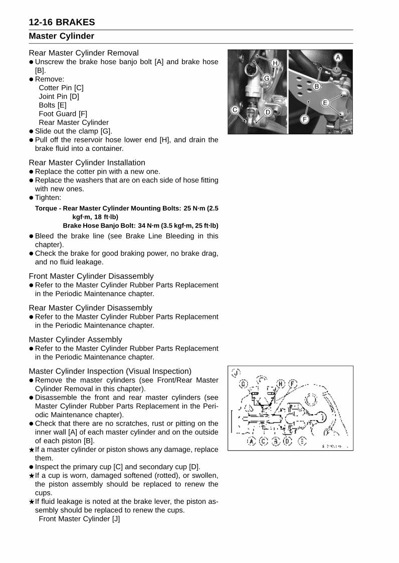
12-16 BRAKESMaster Cylinder
Rear Master Cylinder Removal•Unscrew the brake hose banjo bolt [A] and brake hose
[B].
• Remove:Cotter Pin [C]Joint Pin [D]Bolts [E]Foot Guard [F]Rear Master Cylinder
• Slide out the clamp [G].
• Pull off the reservoir hose lower end [H], and drain thebrake fluid into a container.
Rear Master Cylinder Installation•Replace the cotter pin with a new one.
•Replace the washers that are on each side of hose fittingwith new ones.
• Tighten:Torque - Rear Master Cylinder Mounting Bolts: 25 N·m (2.5
kgf·m, 18 ft·lb)Brake Hose Banjo Bolt: 34 N·m (3.5 kgf·m, 25 ft·lb)
•Bleed the brake line (see Brake Line Bleeding in thischapter).
• Check the brake for good braking power, no brake drag,and no fluid leakage.
Front Master Cylinder Disassembly•Refer to the Master Cylinder Rubber Parts Replacement
in the Periodic Maintenance chapter.
Rear Master Cylinder Disassembly•Refer to the Master Cylinder Rubber Parts Replacement
in the Periodic Maintenance chapter.
Master Cylinder Assembly•Refer to the Master Cylinder Rubber Parts Replacement
in the Periodic Maintenance chapter.
Master Cylinder Inspection (Visual Inspection)•Remove the master cylinders (see Front/Rear Master
Cylinder Removal in this chapter).
• Disassemble the front and rear master cylinders (seeMaster Cylinder Rubber Parts Replacement in the Peri-odic Maintenance chapter).
• Check that there are no scratches, rust or pitting on theinner wall [A] of each master cylinder and on the outsideof each piston [B].If a master cylinder or piston shows any damage, replacethem.
• Inspect the primary cup [C] and secondary cup [D].If a cup is worn, damaged softened (rotted), or swollen,the piston assembly should be replaced to renew thecups.If fluid leakage is noted at the brake lever, the piston as-sembly should be replaced to renew the cups.Front Master Cylinder [J]

BRAKES 12-17Master Cylinder
•Check the dust covers [E] for damage.If they are damaged, replace them.
•Check the piston return spring [F] for any damage.If the springs are damaged, replace them.
•Check that relief port [G] and supply port [H] are notplugged.If the relief port becomes plugged, the brake pads willdrag on the disc. Blow the ports clean with compressedair.Rear Maser Cylinder [K]

12-18 BRAKESBrake Disc
Brake Disc Removal•Remove the wheel (see Front/Rear Wheel Removal in the
Wheels/Tires chapter).
• Unscrew the mounting bolts, and take off the disc.
Brake Disc Installation• Install the brake disc on the wheel so that the marked side
[B] faces out.
• Apply a non-permanent locking agent to the threads ofthe rear brake disc mounting bolts [A].
• Tighten:Torque - Brake Disc Mounting Bolts: 27 N·m (2.8 kgf·m, 20
ft·lb)
Brake Disc Wear•Measure the thickness of each disc [A] at the point where
it has worn the most.If the disc has worn past the service limit, replace it.Measuring Area [B]
Brake Discs ThicknessStandard:
Front 5.3 ∼ 5.7 mm (0.21 ∼ 0.22 in.)
Rear 4.8 ∼ 5.2 mm (0.19 ∼ 0.20 in.)
Service Limit:
Front 5.0 mm (0.20 in.)
Rear 4.5 mm (0.18 in.)
Brake Disc Warp• Jack up the motorcycle so that the wheel is off the ground.
Special Tools - Jack: 57001-1238Jack Attachment: 57001-1608
For front disc inspection, turn the handlebar fully to oneside.
• Set up a dial gauge against the disc [A] as shown andmeasure disc runout, while turning [B] the wheel by hand.If runout exceeds the service limit, replace the disc.
Disc RunoutStandard: 0.15 mm (0.006 in.) or less
Service Limit: 0.3 mm (0.01 in.)
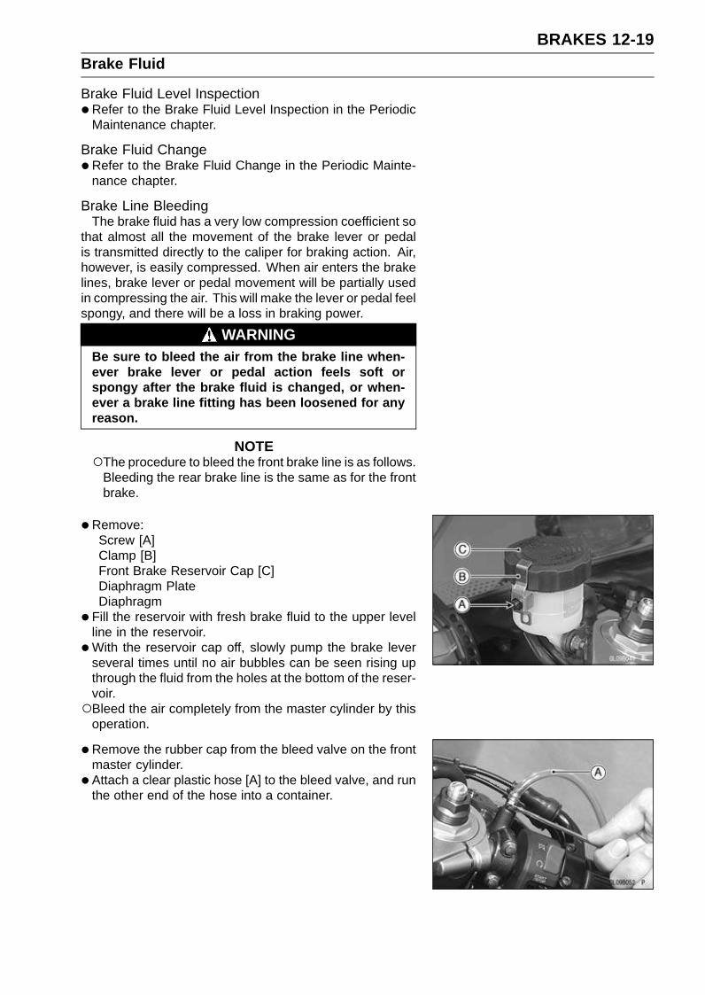
BRAKES 12-19Brake Fluid
Brake Fluid Level Inspection•Refer to the Brake Fluid Level Inspection in the Periodic
Maintenance chapter.
Brake Fluid Change•Refer to the Brake Fluid Change in the Periodic Mainte-
nance chapter.
Brake Line BleedingThe brake fluid has a very low compression coefficient so
that almost all the movement of the brake lever or pedalis transmitted directly to the caliper for braking action. Air,however, is easily compressed. When air enters the brakelines, brake lever or pedal movement will be partially usedin compressing the air. This will make the lever or pedal feelspongy, and there will be a loss in braking power.
WARNINGBe sure to bleed the air from the brake line when-ever brake lever or pedal action feels soft orspongy after the brake fluid is changed, or when-ever a brake line fitting has been loosened for anyreason.
NOTEThe procedure to bleed the front brake line is as follows.
Bleeding the rear brake line is the same as for the frontbrake.
•Remove:Screw [A]Clamp [B]Front Brake Reservoir Cap [C]Diaphragm PlateDiaphragm
•Fill the reservoir with fresh brake fluid to the upper levelline in the reservoir.
•With the reservoir cap off, slowly pump the brake leverseveral times until no air bubbles can be seen rising upthrough the fluid from the holes at the bottom of the reser-voir.Bleed the air completely from the master cylinder by this
operation.
•Remove the rubber cap from the bleed valve on the frontmaster cylinder.
• Attach a clear plastic hose [A] to the bleed valve, and runthe other end of the hose into a container.
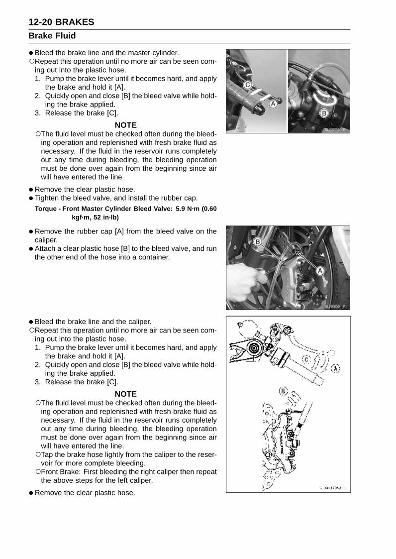
12-20 BRAKESBrake Fluid
•Bleed the brake line and the master cylinder.Repeat this operation until no more air can be seen com-
ing out into the plastic hose.1. Pump the brake lever until it becomes hard, and apply
the brake and hold it [A].2. Quickly open and close [B] the bleed valve while hold-
ing the brake applied.3. Release the brake [C].
NOTEThe fluid level must be checked often during the bleed-
ing operation and replenished with fresh brake fluid asnecessary. If the fluid in the reservoir runs completelyout any time during bleeding, the bleeding operationmust be done over again from the beginning since airwill have entered the line.
•Remove the clear plastic hose.
• Tighten the bleed valve, and install the rubber cap.Torque - Front Master Cylinder Bleed Valve: 5.9 N·m (0.60
kgf·m, 52 in·lb)
•Remove the rubber cap [A] from the bleed valve on thecaliper.
• Attach a clear plastic hose [B] to the bleed valve, and runthe other end of the hose into a container.
• Bleed the brake line and the caliper.Repeat this operation until no more air can be seen com-
ing out into the plastic hose.1. Pump the brake lever until it becomes hard, and apply
the brake and hold it [A].2. Quickly open and close [B] the bleed valve while hold-
ing the brake applied.3. Release the brake [C].
NOTEThe fluid level must be checked often during the bleed-
ing operation and replenished with fresh brake fluid asnecessary. If the fluid in the reservoir runs completelyout any time during bleeding, the bleeding operationmust be done over again from the beginning since airwill have entered the line.Tap the brake hose lightly from the caliper to the reser-
voir for more complete bleeding.Front Brake: First bleeding the right caliper then repeat
the above steps for the left caliper.
•Remove the clear plastic hose.

BRAKES 12-21Brake Fluid
• Install:Diaphragm [A]Diaphragm Plate [B]Front Brake Reservoir Cap [C]Clamp [D]Screw [E]
• Follow the procedure below to install the front/rear brakefluid reservoir cap correctly.First, tighten the brake fluid reservoir cap [B] clockwise
[C] by hand until the resistance is felt fully; then, tightenthe cap an additional 1/6 turn [D] while holding the brakefluid reservoir body [A].
• Tighten the bleed valve, and install the rubber cap.Torque - Bleed Valve: 7.8 N·m (0.80 kgf·m, 69 in·lb)
•Check the fluid level (see Brake Fluid Level Inspection inthe Periodic Maintenance chapter).
• After bleeding is done, check the brake for good brakingpower, no brake drag, and no fluid leakage.

12-22 BRAKESBrake Fluid
WARNINGWhen working with the disc brake, observe the pre-cautions listed below.1. Never reuse old brake fluid.2. Do not use fluid from a container that has been left
unsealed or that has been open for a long time.3. Do not mix two types and brands of fluid for use in
the brake. This lowers the brake fluid boiling pointand could cause the brake to be ineffective. It mayalso cause the rubber brake parts to deteriorate.
4. Don’t leave the reservoir cap off for any length oftime to avoid moisture contamination of the fluid.
5. Don’t change the fluid in the rain or when a strongwind is blowing.
6. Except for the disc pads and disc, use only discbrake fluid, isopropyl alcohol, or ethyl alcohol forcleaning of the brake parts. Do not use any otherfluid for cleaning these parts. Gasoline, engine oil,or any other petroleum distillate will cause deterio-ration of the rubber parts. Oil spilled on any part willbe difficult to wash off completely and will eventuallydeteriorate the rubber used in the disc brake.
7. When handling the disc pads or disc, be careful thatno disc brake fluid or any oil gets on them. Clean offany fluid or oil that inadvertently gets on the pads ordisc with a high-flash point solvent. Do not use onewhich will leave an oily residue. Replace the padswith new ones if they cannot be cleaned satisfacto-rily.
8. Brake fluid quickly ruins painted surfaces; anyspilled fluid should be completely wiped up imme-diately.
9. If any of the brake line fittings or the bleed valve isopened at any time, the AIR MUST BE BLED FROMTHE BRAKE LINE.

BRAKES 12-23Brake Hose
Brake Hose Removal/Installation•Refer to the Brake Hose and Pipe Replacement in the
Periodic Maintenance chapter.
Brake Hose Inspection•Refer to the Brake Hose Damage and Installation Con-
nection Inspection in the Periodic Maintenance chapter.

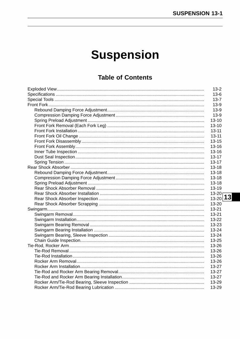
SUSPENSION 13-1
13
Suspension
Table of Contents
Exploded View........................................................................................................................ 13-2Specifications ......................................................................................................................... 13-6Special Tools .......................................................................................................................... 13-7Front Fork ............................................................................................................................... 13-9
Rebound Damping Force Adjustment............................................................................... 13-9Compression Damping Force Adjustment ........................................................................ 13-9Spring Preload Adjustment ............................................................................................... 13-10Front Fork Removal (Each Fork Leg) ............................................................................... 13-10Front Fork Installation ....................................................................................................... 13-11Front Fork Oil Change ...................................................................................................... 13-11Front Fork Disassembly .................................................................................................... 13-15Front Fork Assembly......................................................................................................... 13-16Inner Tube Inspection ....................................................................................................... 13-16Dust Seal Inspection ......................................................................................................... 13-17Spring Tension .................................................................................................................. 13-17
Rear Shock Absorber ............................................................................................................. 13-18Rebound Damping Force Adjustment............................................................................... 13-18Compression Damping Force Adjustment ........................................................................ 13-18Spring Preload Adjustment ............................................................................................... 13-18Rear Shock Absorber Removal ........................................................................................ 13-19Rear Shock Absorber Installation ..................................................................................... 13-20Rear Shock Absorber Inspection ...................................................................................... 13-20Rear Shock Absorber Scrapping ...................................................................................... 13-20
Swingarm................................................................................................................................ 13-21Swingarm Removal........................................................................................................... 13-21Swingarm Installation........................................................................................................ 13-22Swingarm Bearing Removal ............................................................................................. 13-23Swingarm Bearing Installation .......................................................................................... 13-24Swingarm Bearing, Sleeve Inspection .............................................................................. 13-24Chain Guide Inspection..................................................................................................... 13-25
Tie-Rod, Rocker Arm.............................................................................................................. 13-26Tie-Rod Removal .............................................................................................................. 13-26Tie-Rod Installation ........................................................................................................... 13-26Rocker Arm Removal........................................................................................................ 13-26Rocker Arm Installation..................................................................................................... 13-27Tie-Rod and Rocker Arm Bearing Removal...................................................................... 13-27Tie-Rod and Rocker Arm Bearing Installation................................................................... 13-27Rocker Arm/Tie-Rod Bearing, Sleeve Inspection ............................................................. 13-29Rocker Arm/Tie-Rod Bearing Lubrication ......................................................................... 13-29
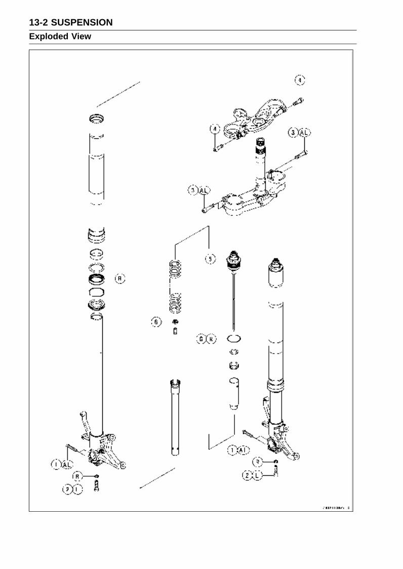
13-2 SUSPENSIONExploded View
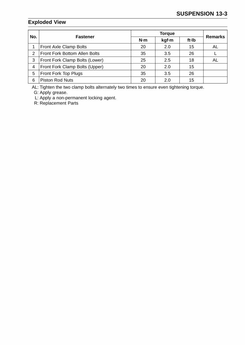
SUSPENSION 13-3Exploded View
TorqueNo. Fastener
N·m kgf·m ft·lbRemarks
1 Front Axle Clamp Bolts 20 2.0 15 AL
2 Front Fork Bottom Allen Bolts 35 3.5 26 L
3 Front Fork Clamp Bolts (Lower) 25 2.5 18 AL
4 Front Fork Clamp Bolts (Upper) 20 2.0 15
5 Front Fork Top Plugs 35 3.5 26
6 Piston Rod Nuts 20 2.0 15
AL: Tighten the two clamp bolts alternately two times to ensure even tightening torque.G: Apply grease.L: Apply a non-permanent locking agent.R: Replacement Parts

13-4 SUSPENSIONExploded View
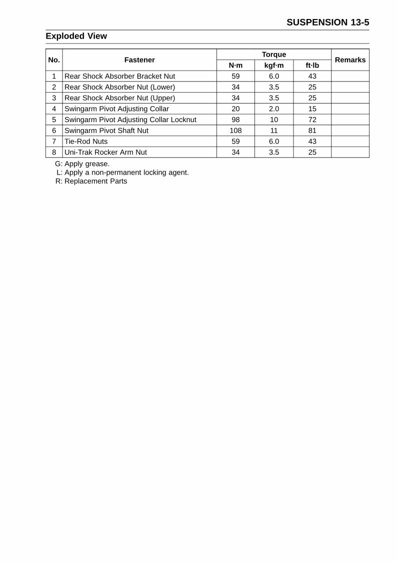
SUSPENSION 13-5Exploded View
TorqueNo. Fastener
N·m kgf·m ft·lbRemarks
1 Rear Shock Absorber Bracket Nut 59 6.0 43
2 Rear Shock Absorber Nut (Lower) 34 3.5 25
3 Rear Shock Absorber Nut (Upper) 34 3.5 25
4 Swingarm Pivot Adjusting Collar 20 2.0 15
5 Swingarm Pivot Adjusting Collar Locknut 98 10 72
6 Swingarm Pivot Shaft Nut 108 11 81
7 Tie-Rod Nuts 59 6.0 43
8 Uni-Trak Rocker Arm Nut 34 3.5 25
G: Apply grease.L: Apply a non-permanent locking agent.R: Replacement Parts

13-6 SUSPENSIONSpecifications
Item StandardFront Fork (Per One Unit)
Fork Inner Tube Diameter 41 mm (1.6 in.)
Air Pressure Atmospheric pressure (non-adjustable)
Rebound Damper Setting 1 3/4 turns out from the fully clockwise position(Usable range: 0 ←→ 2 turns out)
Compression Damper Setting 3/4 turn out from the fully clockwise position(Usable range: 0 ←→ 2 turns out)
Fork Spring Preload Setting Adjuster protrusion is 17 mm (0.67 in.)(Usable range: 10 ∼ 25 mm) (0.39 ∼ 0.98 in.)
Fork Oil:
Viscosity SS05 or equivalent SAE 5W
Amount:
When Changing Oil Approx. 360 mL (12.2 US oz.)
After Disassembly andCompletely Dry
426 ±2 mL (14.4 ±0.07 US oz.)
Fork Oil Level: (Fully Compressed,without Spring, below from the Topof the Inner Tube)
109 ±2 mm (4.29 ±0.08 in.)
Fork Spring Free Length 247.6 mm (9.75 in.) (Service Limit: 243 mm (9.58 in.))
Rear Shock AbsorberRebound Damper Set 9th click from the first click of the fully clockwise position
(Usable range: 0 ←→ 2 turns out)
Compression Damper Set 3/4 turn out from the fully clockwise position(Usable range: 0 ←→ 2 turns out)
Spring Preload Setting Position:
Standard Spring length: 182.7 mm (7.19 in.)
Usable Range Spring length: 177.7 ∼ 187.7 mm (6.996 ∼ 7.390 in.)(weaker to stronger)
Gas Pressure 1 500 kPa (15.3 kgf/cm², 218 psi, non-adjustable)
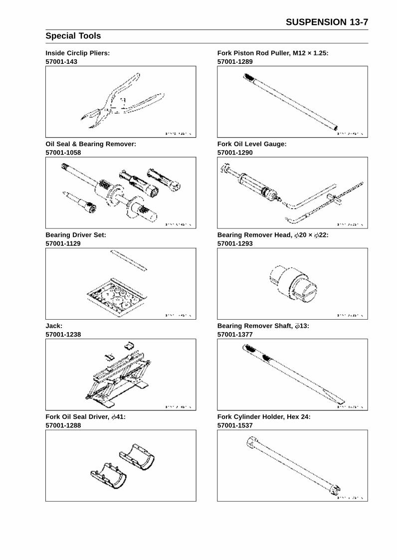
SUSPENSION 13-7Special Tools
Inside Circlip Pliers:57001-143
Oil Seal & Bearing Remover:57001-1058
Bearing Driver Set:57001-1129
Jack:57001-1238
Fork Oil Seal Driver, 41:57001-1288
Fork Piston Rod Puller, M12 × 1.25:57001-1289
Fork Oil Level Gauge:57001-1290
Bearing Remover Head, 20 × 22:57001-1293
Bearing Remover Shaft, 13:57001-1377
Fork Cylinder Holder, Hex 24:57001-1537

13-8 SUSPENSIONSpecial Tools
Hook Wrench T=3.2 R37:57001-1539
Fork Spring Compressor:57001-1587
Swingarm Pivot Nut Wrench:57001-1597
Jack Attachment:57001-1608
Needle Bearing Driver, 17/ 18:57001-1609
Stem Bearing Driver, 28:57001-1610
Clamp:57001-1626
Spacer, 18:57001-1636
Spacer, 28:57001-1637
Hook Wrench R37:57001-1641

SUSPENSION 13-9Front Fork
Rebound Damping Force Adjustment•To adjust the rebound damping force, turn the rebound
damping adjuster [A] until you feel a click.The standard adjuster setting for the average-build rider
of 68 kg (150 lb) with no passenger and no accessoriesis the 1 3/4 turns out from the fully clockwise position.
WARNINGIf both adjusters are not adjusted equally, handlingmay be impaired and a hazardous condition mayresult.
The damping force can be left soft for average riding. Butit should be adjusted harder for high speed riding or ridingwith a passenger. If the damping feels too soft or too stiff,adjust it in accordance with the following table.
Rebound Damping Force Adjustment
AdjusterPosition
DampingForce
Setting Load Road Speed
2 TurnsOut
Weak Soft Light Good Low
↑ ↑ ↑ ↑ ↑ ↑↓ ↓ ↓ ↓ ↓ ↓0 Strong Hard Heavy Bad High
Compression Damping Force Adjustment•To adjust the compression damping force, turn the com-
pression damping adjuster [A] until you feel a click.The standard adjuster setting for the average-build rider
of 68 kg (150 lb) with no passenger and no accessoriesis the 3/4 turn out from the fully clockwise position.
WARNINGIf both adjusters are not adjusted equally, handlingmay be impaired and a hazardous condition mayresult.
The damping force can be left soft for average riding. Butit should be adjusted harder for high speed riding or ridingwith a passenger. If the damping feels too soft or too stiff,adjust it in accordance with the following table.
Compression Damping Force Adjustment
AdjusterPosition
DampingForce
Setting Load Road Speed
2 TurnsOut
Weak Soft Light Good Low
↑ ↑ ↑ ↑ ↑ ↑↓ ↓ ↓ ↓ ↓ ↓0 Strong Hard Heavy Bad High
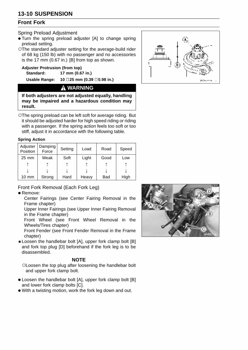
13-10 SUSPENSIONFront Fork
Spring Preload Adjustment•Turn the spring preload adjuster [A] to change spring
preload setting.The standard adjuster setting for the average-build rider
of 68 kg (150 lb) with no passenger and no accessoriesis the 17 mm (0.67 in.) [B] from top as shown.
Adjuster Protrusion (from top)Standard: 17 mm (0.67 in.)
Usable Range: 10 ∼ 25 mm (0.39 ∼ 0.98 in.)
WARNINGIf both adjusters are not adjusted equally, handlingmay be impaired and a hazardous condition mayresult.
The spring preload can be left soft for average riding. Butit should be adjusted harder for high speed riding or ridingwith a passenger. If the spring action feels too soft or toostiff, adjust it in accordance with the following table.
Spring Action
AdjusterPosition
DampingForce
Setting Load Road Speed
25 mm Weak Soft Light Good Low
↑ ↑ ↑ ↑ ↑ ↑↓ ↓ ↓ ↓ ↓ ↓
10 mm Strong Hard Heavy Bad High
Front Fork Removal (Each Fork Leg)•Remove:
Center Fairings (see Center Fairing Removal in theFrame chapter)Upper Inner Fairings (see Upper Inner Fairing Removalin the Frame chapter)Front Wheel (see Front Wheel Removal in theWheels/Tires chapter)Front Fender (see Front Fender Removal in the Framechapter)
Loosen the handlebar bolt [A], upper fork clamp bolt [B]and fork top plug [D] beforehand if the fork leg is to bedisassembled.
NOTELoosen the top plug after loosening the handlebar bolt
and upper fork clamp bolt.
• Loosen the handlebar bolt [A], upper fork clamp bolt [B]and lower fork clamp bolts [C].
•With a twisting motion, work the fork leg down and out.

SUSPENSION 13-11Front Fork
Front Fork Installation• Install the fork so that the top end [A] of the outer tube as
shown.6.5 mm (0.26 in.) [B]
• Tighten the lower fork clamp bolts and fork top plug.Torque - Front Fork Clamp Bolts (Lower): 25 N·m (2.5
kgf·m, 18 ft·lb)Front Fork Top Plug: 35 N·m (3.5 kgf·m, 26 ft·lb)
•Tighten the handlebar bolt and upper fork clamp bolt.
Torque - Handlebar Bolt: 25 N·m (2.5 kgf·m, 18 ft·lb)Front Fork Clamp Bolt (Upper): 20 N·m (2.0 kgf·m,
15 ft·lb)
NOTETighten the two clamp bolts alternately two times to en-
sure even tightening torque.Tighten the top plug before tightening the handlebar bolt
and upper fork clamp bolt.
• Install the removed parts (see appropriate chapters).
• Adjust the spring preload and the damping force.
Front Fork Oil Change•Remove the front fork (see Front Fork Removal in this
chapter).
• Hold the inner tube lower end in a vise.
•Unscrew the top plug [A] out of the outer tube.
• Install the clamps [A] as shown.
NOTESet the three grooves of clamp to the three pins [B] of
front fork, pull up the outer tube [C] to hold it by theclamps, and then tighten the two bolts [D].
Special Tools - Fork Spring Compressor: 57001-1587Clamp: 57001-1626

13-12 SUSPENSIONFront Fork
• Insert the holder bar [A] into the axle hole of the front fork[B].
• Insert the compression shaft and install the nut.
• Insert the lower end of the compression shaft [A] into thehole [B] of the holder bar.
• Screw the adjust nut [A] onto the compression shaft asshown.
• Screw the locknut [B].About 20 mm (0.79 in.) [C]
• Set the other side compression shaft same process.
• Set the holder bar [A] and compression shafts [B].
• Screw in nuts [A] come out the piston rod nut.
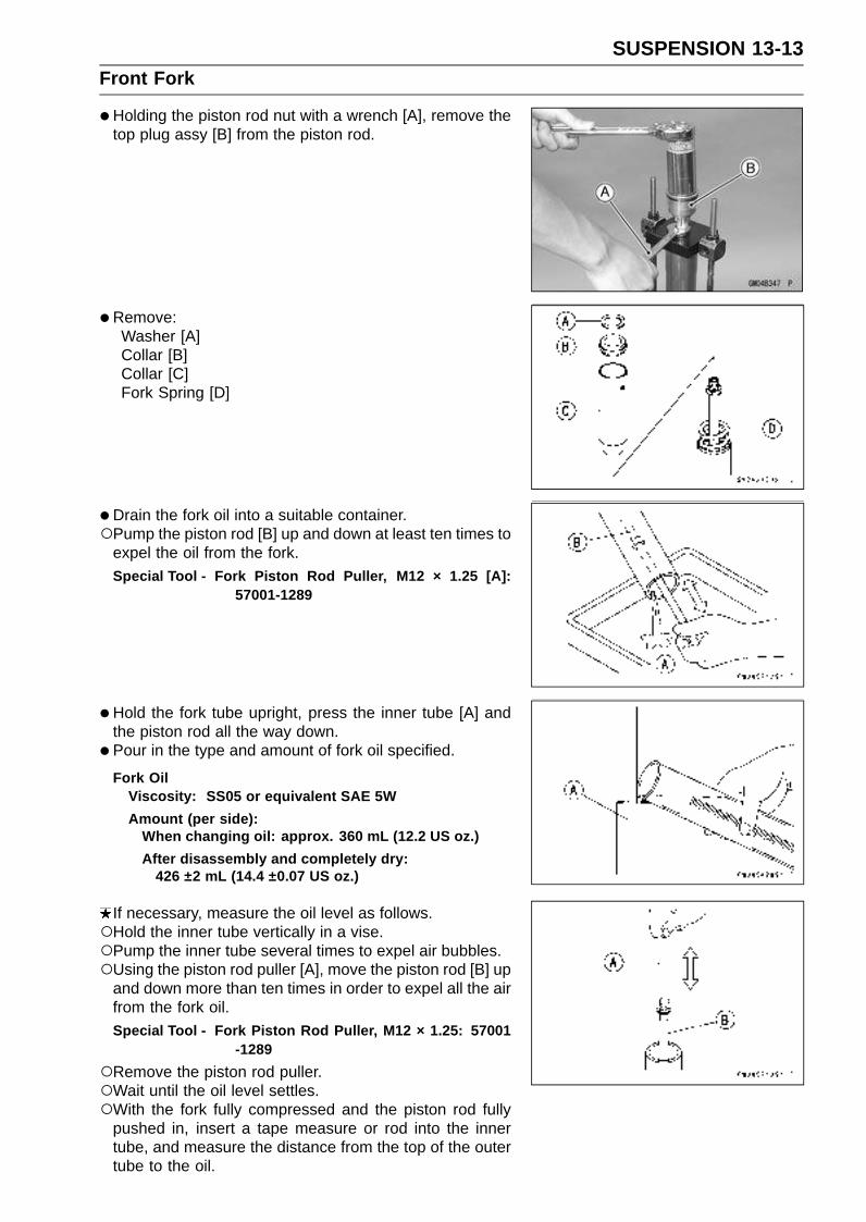
SUSPENSION 13-13Front Fork
•Holding the piston rod nut with a wrench [A], remove thetop plug assy [B] from the piston rod.
•Remove:Washer [A]Collar [B]Collar [C]Fork Spring [D]
•Drain the fork oil into a suitable container.Pump the piston rod [B] up and down at least ten times to
expel the oil from the fork.Special Tool - Fork Piston Rod Puller, M12 × 1.25 [A]:
57001-1289
•Hold the fork tube upright, press the inner tube [A] andthe piston rod all the way down.
• Pour in the type and amount of fork oil specified.
Fork OilViscosity: SS05 or equivalent SAE 5W
Amount (per side):When changing oil: approx. 360 mL (12.2 US oz.)
After disassembly and completely dry:426 ±2 mL (14.4 ±0.07 US oz.)
If necessary, measure the oil level as follows.Hold the inner tube vertically in a vise.Pump the inner tube several times to expel air bubbles.Using the piston rod puller [A], move the piston rod [B] up
and down more than ten times in order to expel all the airfrom the fork oil.Special Tool - Fork Piston Rod Puller, M12 × 1.25: 57001
-1289
Remove the piston rod puller.Wait until the oil level settles.With the fork fully compressed and the piston rod fully
pushed in, insert a tape measure or rod into the innertube, and measure the distance from the top of the outertube to the oil.
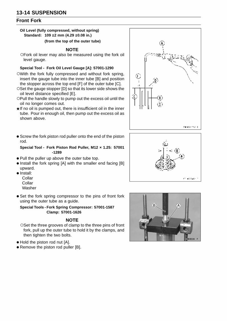
13-14 SUSPENSIONFront Fork
Oil Level (fully compressed, without spring)Standard: 109 ±2 mm (4.29 ±0.08 in.)
(from the top of the outer tube)
NOTEFork oil lever may also be measured using the fork oil
level gauge.
Special Tool - Fork Oil Level Gauge [A]: 57001-1290
With the fork fully compressed and without fork spring,insert the gauge tube into the inner tube [B] and positionthe stopper across the top end [F] of the outer tube [C].Set the gauge stopper [D] so that its lower side shows the
oil level distance specified [E].Pull the handle slowly to pump out the excess oil until the
oil no longer comes out.If no oil is pumped out, there is insufficient oil in the innertube. Pour in enough oil, then pump out the excess oil asshown above.
• Screw the fork piston rod puller onto the end of the pistonrod.Special Tool - Fork Piston Rod Puller, M12 × 1.25: 57001
-1289
•Pull the puller up above the outer tube top.
• Install the fork spring [A] with the smaller end facing [B]upward.
• Install:CollarCollarWasher
• Set the fork spring compressor to the pins of front forkusing the outer tube as a guide.Special Tools - Fork Spring Compressor: 57001-1587
Clamp: 57001-1626
NOTESet the three grooves of clamp to the three pins of front
fork, pull up the outer tube to hold it by the clamps, andthen tighten the two bolts.
•Hold the piston rod nut [A].
• Remove the piston rod puller [B].
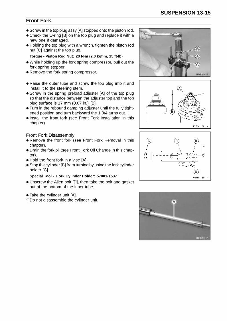
SUSPENSION 13-15Front Fork
•Screw in the top plug assy [A] stopped onto the piston rod.
•Check the O-ring [B] on the top plug and replace it with anew one if damaged.
•Holding the top plug with a wrench, tighten the piston rodnut [C] against the top plug.Torque - Piston Rod Nut: 20 N·m (2.0 kgf·m, 15 ft·lb)
•While holding up the fork spring compressor, pull out thefork spring stopper.
•Remove the fork spring compressor.
• Raise the outer tube and screw the top plug into it andinstall it to the steering stem.
•Screw in the spring preload adjuster [A] of the top plugso that the distance between the adjuster top and the topplug surface is 17 mm (0.67 in.) [B].
• Turn in the rebound damping adjuster until the fully tight-ened position and turn backward the 1 3/4 turns out.
• Install the front fork (see Front Fork Installation in thischapter).
Front Fork Disassembly•Remove the front fork (see Front Fork Removal in this
chapter).
• Drain the fork oil (see Front Fork Oil Change in this chap-ter).
• Hold the front fork in a vise [A].
• Stop the cylinder [B] from turning by using the fork cylinderholder [C].
Special Tool - Fork Cylinder Holder: 57001-1537
•Unscrew the Allen bolt [D], then take the bolt and gasketout of the bottom of the inner tube.
• Take the cylinder unit [A].Do not disassemble the cylinder unit.
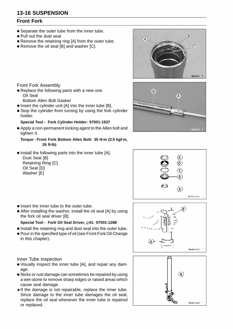
13-16 SUSPENSIONFront Fork
•Separate the outer tube from the inner tube.
• Pull out the dust seal.
• Remove the retaining ring [A] from the outer tube.
•Remove the oil seal [B] and washer [C].
Front Fork Assembly•Replace the following parts with a new one.
Oil SealBottom Allen Bolt Gasket
• Insert the cylinder unit [A] into the inner tube [B].
• Stop the cylinder from turning by using the fork cylinderholder.Special Tool - Fork Cylinder Holder: 57001-1537
•Apply a non-permanent locking agent to the Allen bolt andtighten it.Torque - Front Fork Bottom Allen Bolt: 35 N·m (3.5 kgf·m,
26 ft·lb)
• Install the following parts into the inner tube [A].Dust Seal [B]Retaining Ring [C]Oil Seal [D]Washer [E]
• Insert the inner tube to the outer tube.
• After installing the washer, install the oil seal [A] by usingthe fork oil seal driver [B].
Special Tool - Fork Oil Seal Driver, 41: 57001-1288
• Install the retaining ring and dust seal into the outer tube.
• Pour in the specified type of oil (see Front Fork Oil Changein this chapter).
Inner Tube Inspection•Visually inspect the inner tube [A], and repair any dam-
age.
•Nicks or rust damage can sometimes be repaired by usinga wet-stone to remove sharp edges or raised areas whichcause seal damage.If the damage is not repairable, replace the inner tube.Since damage to the inner tube damages the oil seal,replace the oil seal whenever the inner tube is repairedor replaced.
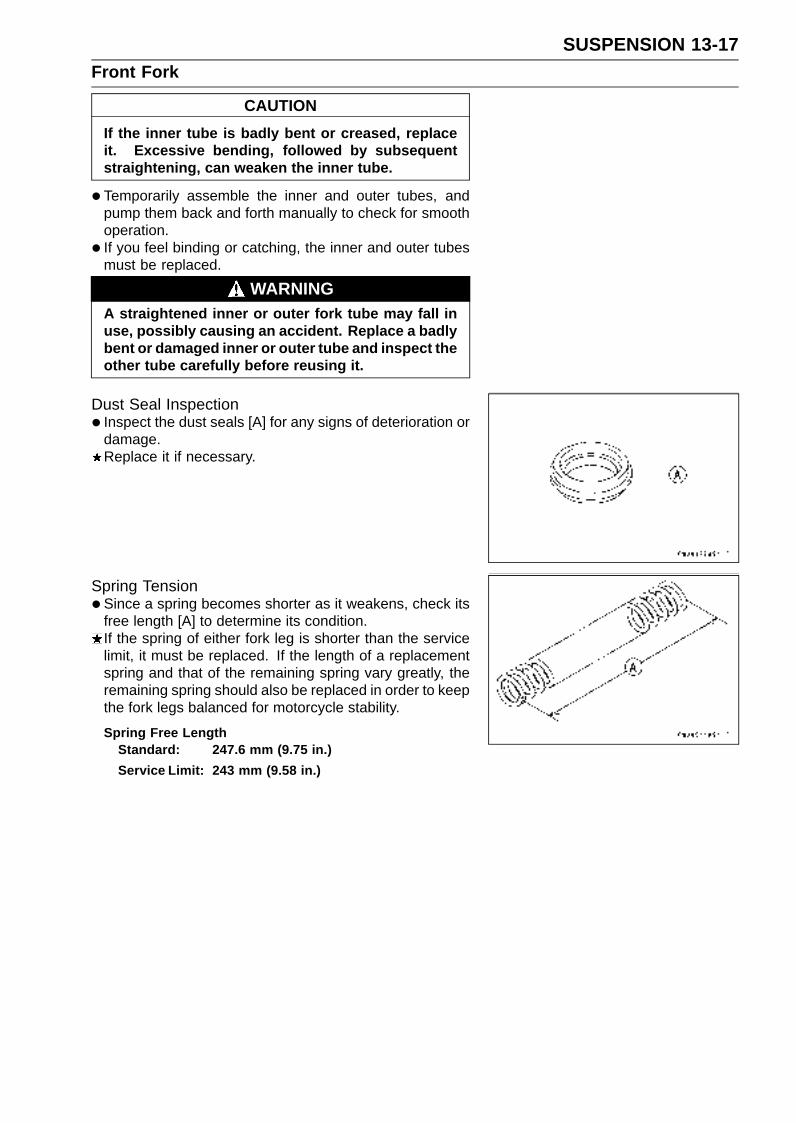
SUSPENSION 13-17Front Fork
CAUTION
If the inner tube is badly bent or creased, replaceit. Excessive bending, followed by subsequentstraightening, can weaken the inner tube.
•Temporarily assemble the inner and outer tubes, andpump them back and forth manually to check for smoothoperation.
• If you feel binding or catching, the inner and outer tubesmust be replaced.
WARNINGA straightened inner or outer fork tube may fall inuse, possibly causing an accident. Replace a badlybent or damaged inner or outer tube and inspect theother tube carefully before reusing it.
Dust Seal Inspection• Inspect the dust seals [A] for any signs of deterioration or
damage.Replace it if necessary.
Spring Tension•Since a spring becomes shorter as it weakens, check its
free length [A] to determine its condition.If the spring of either fork leg is shorter than the servicelimit, it must be replaced. If the length of a replacementspring and that of the remaining spring vary greatly, theremaining spring should also be replaced in order to keepthe fork legs balanced for motorcycle stability.
Spring Free LengthStandard: 247.6 mm (9.75 in.)
Service Limit: 243 mm (9.58 in.)
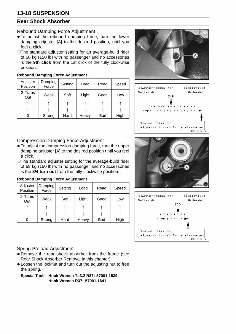
13-18 SUSPENSIONRear Shock Absorber
Rebound Damping Force Adjustment•To adjust the rebound damping force, turn the lower
damping adjuster [A] to the desired position, until youfeel a click.The standard adjuster setting for an average-build rider
of 68 kg (150 lb) with no passenger and no accessoriesis the 9th click from the 1st click of the fully clockwiseposition.
Rebound Damping Force Adjustment
AdjusterPosition
DampingForce
Setting Load Road Speed
2 TurnsOut
Weak Soft Light Good Low
↑ ↑ ↑ ↑ ↑ ↑↓ ↓ ↓ ↓ ↓ ↓0 Strong Hard Heavy Bad High
Compression Damping Force Adjustment•To adjust the compression damping force, turn the upper
damping adjuster [A] to the desired position until you feela click.The standard adjuster setting for the average-build rider
of 68 kg (150 lb) with no passenger and no accessoriesis the 3/4 turn out from the fully clockwise position.
Rebound Damping Force Adjustment
AdjusterPosition
DampingForce
Setting Load Road Speed
2 TurnsOut
Weak Soft Light Good Low
↑ ↑ ↑ ↑ ↑ ↑↓ ↓ ↓ ↓ ↓ ↓0 Strong Hard Heavy Bad High
Spring Preload Adjustment•Remove the rear shock absorber from the frame (see
Rear Shock Absorber Removal in this chapter).
• Loosen the locknut and turn out the adjusting nut to freethe spring.Special Tools - Hook Wrench T=3.2 R37: 57001-1539
Hook Wrench R37: 57001-1641

SUSPENSION 13-19Rear Shock Absorber
•To adjust the spring preload, turn in the adjusting nut [A]to the desired position and tighten the locknut [B].Spring Length [C]
Spring Preload SettingStandard: Spring length 182.7 mm (7.19 in.)
Usable Range: Spring length 177.7 ∼ 187.7 mm (6.996∼ 7.390 in.)
The standard adjusting nut setting for an average-buildrider of 68 kg (150 lb) with no passenger and no acces-sories is 180 mm (7.0 in.) spring length.
•Remove the bolts [A], chain cover [B] and left foot guard[C] for turning the hook wrench easily.
• To adjust the spring preload, turn in the adjusting nut tothe desired position and tighten the locknut by using hookwrenches [A] with the rear shock absorber attached theframe.Special Tools - Hook Wrench T=3.2 R37: 57001-1539
Hook Wrench R37: 57001-1641
If the spring action feels too soft or too stiff, adjust it.
Spring Adjustment
AdjusterPosition
DampingForce
Setting Load Road Speed
187.7 mm(7.390 in.)
Weak Soft Light Good Low
↑ ↑ ↑ ↑ ↑ ↑↓ ↓ ↓ ↓ ↓ ↓
177.7 mm(6.996 in.) Strong Hard Heavy Bad High
Rear Shock Absorber Removal•Remove:
Lower Fairings (see Lower Fairings Removal in theFrame chapter).
• Using the jack, raise the rear wheel off the ground.Special Tools - Jack: 57001-1238
Jack Attachment: 57001-1608
•Squeeze the brake lever slowly and it with a band [A].
WARNINGBe sure to hold the front brake when removing theshock absorber, or the motorcycle may fall over. Itcould cause an accident and injury.

13-20 SUSPENSIONRear Shock Absorber
•Remove:Lower Shock Absorber Nut and Bolt [A]Upper Tie-Rod Nut and Bolt [B]Upper Shock Absorber Nut and Bolt [C]
•Remove the shock absorber downward.
Rear Shock Absorber Installation•Tighten:
Torque - Rear Shock Absorber Nuts: 34 N·m (3.5 kgf·m, 25ft·lb)
Tie-Rod Nuts: 59 N·m (6.0 kgf·m, 43 ft·lb)
Rear Shock Absorber Inspection•Remove the rear shock absorber (see Rear Shock Ab-
sorber Removal in this chapter).
• Visually inspect the following items.Smooth StrokeOil LeakageCrack or Dent
If there is any damage to the rear shock absorber, replaceit.
• Visually inspect the bushing.If it show any signs of damage, replace it.
Rear Shock Absorber Scrapping
WARNINGSince the reservoir tank of the rear shock absorbercontains nitrogen gas, do not incinerate the reser-voir tank without first releasing the gas or it mayexplode.
•Remove the valve cap and release the nitrogen gas com-pletely from the gas reservoir.
• Remove the valve [A].
WARNINGSince the high pressure gas is dangerous, do notpoint the valve toward your face or body.
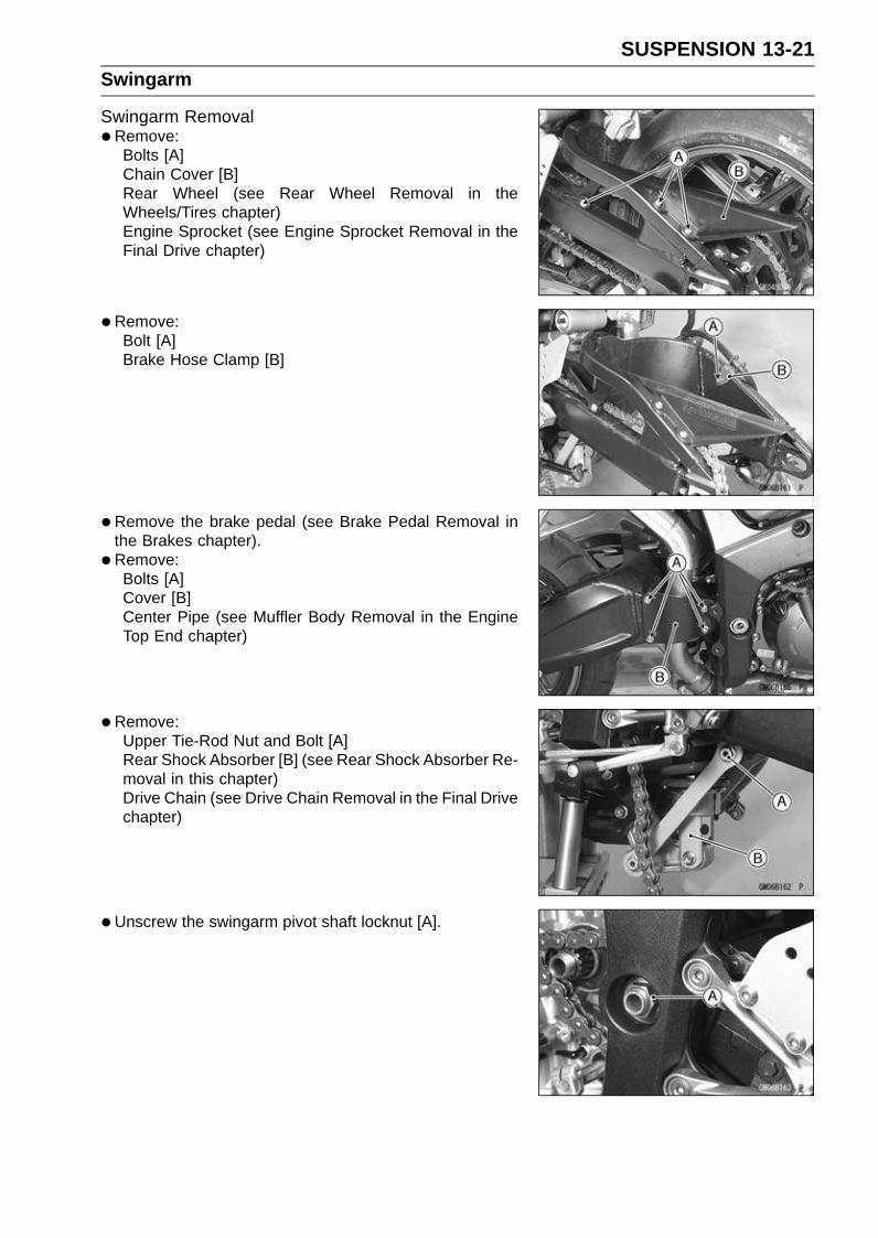
SUSPENSION 13-21Swingarm
Swingarm Removal•Remove:
Bolts [A]Chain Cover [B]Rear Wheel (see Rear Wheel Removal in theWheels/Tires chapter)Engine Sprocket (see Engine Sprocket Removal in theFinal Drive chapter)
•Remove:Bolt [A]Brake Hose Clamp [B]
•Remove the brake pedal (see Brake Pedal Removal inthe Brakes chapter).
• Remove:Bolts [A]Cover [B]Center Pipe (see Muffler Body Removal in the EngineTop End chapter)
•Remove:Upper Tie-Rod Nut and Bolt [A]Rear Shock Absorber [B] (see Rear Shock Absorber Re-moval in this chapter)Drive Chain (see Drive Chain Removal in the Final Drivechapter)
•Unscrew the swingarm pivot shaft locknut [A].
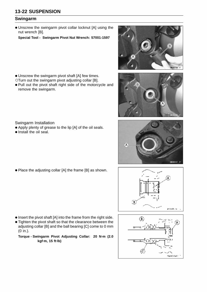
13-22 SUSPENSIONSwingarm
•Unscrew the swingarm pivot collar locknut [A] using thenut wrench [B].Special Tool - Swingarm Pivot Nut Wrench: 57001-1597
•Unscrew the swingarm pivot shaft [A] few times.Turn out the swingarm pivot adjusting collar [B].
• Pull out the pivot shaft right side of the motorcycle andremove the swingarm.
Swingarm Installation•Apply plenty of grease to the lip [A] of the oil seals.
• Install the oil seal.
• Place the adjusting collar [A] the frame [B] as shown.
• Insert the pivot shaft [A] into the frame from the right side.
• Tighten the pivot shaft so that the clearance between theadjusting collar [B] and the ball bearing [C] come to 0 mm(0 in.).Torque - Swingarm Pivot Adjusting Collar: 20 N·m (2.0
kgf·m, 15 ft·lb)
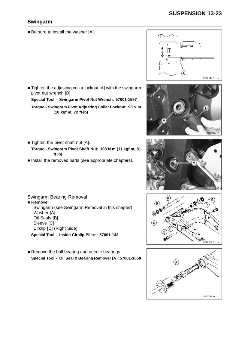
SUSPENSION 13-23Swingarm
•Be sure to install the washer [A].
• Tighten the adjusting collar locknut [A] with the swingarmpivot nut wrench [B].Special Tool - Swingarm Pivot Nut Wrench: 57001-1597
Torque - Swingarm Pivot Adjusting Collar Locknut: 98 N·m(10 kgf·m, 72 ft·lb)
•Tighten the pivot shaft nut [A].Torque - Swingarm Pivot Shaft Nut: 108 N·m (11 kgf·m, 81
ft·lb)
• Install the removed parts (see appropriate chapters).
Swingarm Bearing Removal•Remove:
Swingarm (see Swingarm Removal in this chapter)Washer [A]Oil Seals [B]Sleeve [C]Circlip [D] (Right Side)
Special Tool - Inside Circlip Pliers: 57001-143
•Remove the ball bearing and needle bearings.Special Tool - Oil Seal & Bearing Remover [A]: 57001-1058

13-24 SUSPENSIONSwingarm
Swingarm Bearing Installation•Replace the ball and needle bearings [A] with new ones.
• Install the ball and needle bearings so that the manufac-turer’s marks face out.Special Tools - Bearing Driver Set: 57001-1129
Needle Bearing Driver, 28 [B]: 57001-1610Spacer, 28: 57001-1637
• Install the needle bearings [A], ball bearing [B] and oilseals [C] position as shown.Circlip [D]32.5 mm (1.28 in.) [E]17 mm (0.67 in.) [F]0.5 mm (0.02 in.) [G]1 mm (0.04 in.) [H]5 mm (0.20 in.) [I]
Swingarm Bearing, Sleeve Inspection
CAUTION
Do not remove the bearings for inspection. Re-moval may damage them.
• Inspect the needle bearings [A] and ball bearing installedin the swingarm.The rollers and ball in a bearing normally wear very little,
and wear is difficult to measure. Instead of measuring,visually inspect the bearing for abrasion, discoloration, orother damage.If the needle bearing and sleeve [B] show any sings ofabnormal wear, discoloration, or damage, replace themas a set.

SUSPENSION 13-25Swingarm
•Turn the bearing in the coupling back and forth [A] whilechecking for plays, roughness, or binding.If bearing play, roughness, or binding is found, replacethe bearing.
• Examine the bearing seal [B] for tears or leakage.If the seal is torn or is leaking, replace the bearing.
Chain Guide Inspection•Refer to the Chain Guide Wear Inspection in the Periodic
Maintenance chapter.
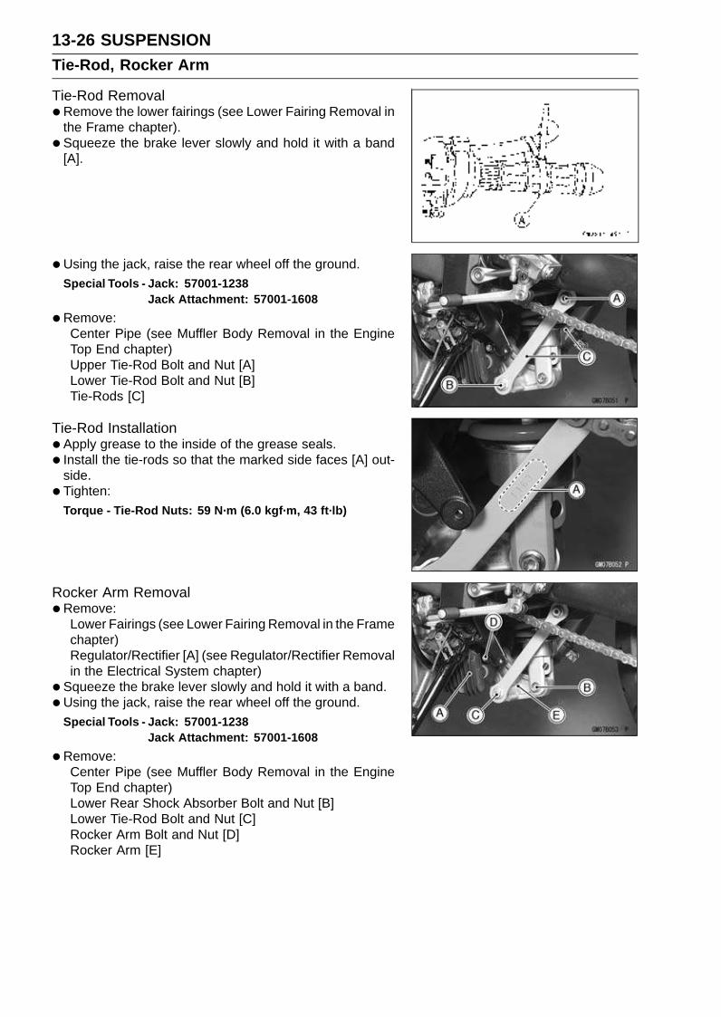
13-26 SUSPENSIONTie-Rod, Rocker Arm
Tie-Rod Removal•Remove the lower fairings (see Lower Fairing Removal in
the Frame chapter).
• Squeeze the brake lever slowly and hold it with a band[A].
• Using the jack, raise the rear wheel off the ground.Special Tools - Jack: 57001-1238
Jack Attachment: 57001-1608
•Remove:Center Pipe (see Muffler Body Removal in the EngineTop End chapter)Upper Tie-Rod Bolt and Nut [A]Lower Tie-Rod Bolt and Nut [B]Tie-Rods [C]
Tie-Rod Installation•Apply grease to the inside of the grease seals.
• Install the tie-rods so that the marked side faces [A] out-side.
• Tighten:Torque - Tie-Rod Nuts: 59 N·m (6.0 kgf·m, 43 ft·lb)
Rocker Arm Removal•Remove:
Lower Fairings (see Lower Fairing Removal in the Framechapter)Regulator/Rectifier [A] (see Regulator/Rectifier Removalin the Electrical System chapter)
• Squeeze the brake lever slowly and hold it with a band.
•Using the jack, raise the rear wheel off the ground.Special Tools - Jack: 57001-1238
Jack Attachment: 57001-1608
•Remove:Center Pipe (see Muffler Body Removal in the EngineTop End chapter)Lower Rear Shock Absorber Bolt and Nut [B]Lower Tie-Rod Bolt and Nut [C]Rocker Arm Bolt and Nut [D]Rocker Arm [E]
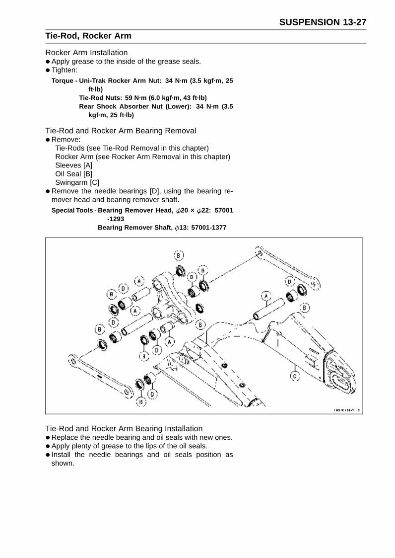
SUSPENSION 13-27Tie-Rod, Rocker Arm
Rocker Arm Installation•Apply grease to the inside of the grease seals.
• Tighten:
Torque - Uni-Trak Rocker Arm Nut: 34 N·m (3.5 kgf·m, 25ft·lb)
Tie-Rod Nuts: 59 N·m (6.0 kgf·m, 43 ft·lb)Rear Shock Absorber Nut (Lower): 34 N·m (3.5
kgf·m, 25 ft·lb)
Tie-Rod and Rocker Arm Bearing Removal•Remove:
Tie-Rods (see Tie-Rod Removal in this chapter)Rocker Arm (see Rocker Arm Removal in this chapter)Sleeves [A]Oil Seal [B]Swingarm [C]
•Remove the needle bearings [D], using the bearing re-mover head and bearing remover shaft.Special Tools - Bearing Remover Head, 20 × 22: 57001
-1293Bearing Remover Shaft, 13: 57001-1377
Tie-Rod and Rocker Arm Bearing Installation•Replace the needle bearing and oil seals with new ones.
• Apply plenty of grease to the lips of the oil seals.
• Install the needle bearings and oil seals position asshown.
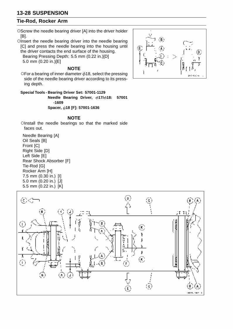
13-28 SUSPENSIONTie-Rod, Rocker Arm
Screw the needle bearing driver [A] into the driver holder[B].Insert the needle bearing driver into the needle bearing
[C] and press the needle bearing into the housing untilthe driver contacts the end surface of the housing.Bearing Pressing Depth: 5.5 mm (0.22 in.)[D]5.0 mm (0.20 in.)[E]
NOTEFor a bearing of inner diameter 18, select the pressing
side of the needle bearing driver according to its press-ing depth.
Special Tools - Bearing Driver Set: 57001-1129Needle Bearing Driver, 17/ 18: 57001
-1609Spacer, 18 [F]: 57001-1636
NOTEInstall the needle bearings so that the marked side
faces out.
Needle Bearing [A]Oil Seals [B]Front [C]Right Side [D]Left Side [E]Rear Shock Absorber [F]Tie-Rod [G]Rocker Arm [H]7.5 mm (0.30 in.) [I]5.0 mm (0.20 in.) [J]5.5 mm (0.22 in.) [K]

SUSPENSION 13-29Tie-Rod, Rocker Arm
Rocker Arm/Tie-Rod Bearing, Sleeve Inspection
CAUTION
Do not remove the bearings for inspection. Re-moval may damage them.
•Visually inspect the locker arm, or tie-rod sleeves [A] andneedle bearings [B].
• The rollers in a needle bearing normally wear very little,and wear is difficult to measure. Instead of measuring,inspect the bearing for abrasion, color change, or otherdamage.If there is any doubt as to the condition of any of theneedle bearings or sleeve replace the sleeve and nee-dle bearings as a set.
Rocker Arm/Tie-Rod Bearing Lubrication
NOTESince the bearings are packed with grease, lubrication
is not required.


STEERING 14-1
14
Steering
Table of Contents
Exploded View........................................................................................................................ 14-2Special Tools .......................................................................................................................... 14-4Steering .................................................................................................................................. 14-5
Steering Inspection ........................................................................................................... 14-5Steering Adjustment.......................................................................................................... 14-5
Steering Stem......................................................................................................................... 14-6Stem, Stem Bearing Removal........................................................................................... 14-6Stem, Stem Bearing Installation........................................................................................ 14-7Steering Stem Bearing Lubrication ................................................................................... 14-9Steering Stem Warp.......................................................................................................... 14-9Stem Cap Deterioration, Damage..................................................................................... 14-9
Handlebar ............................................................................................................................... 14-10Handlebar Removal .......................................................................................................... 14-10Handlebar Installation ....................................................................................................... 14-10
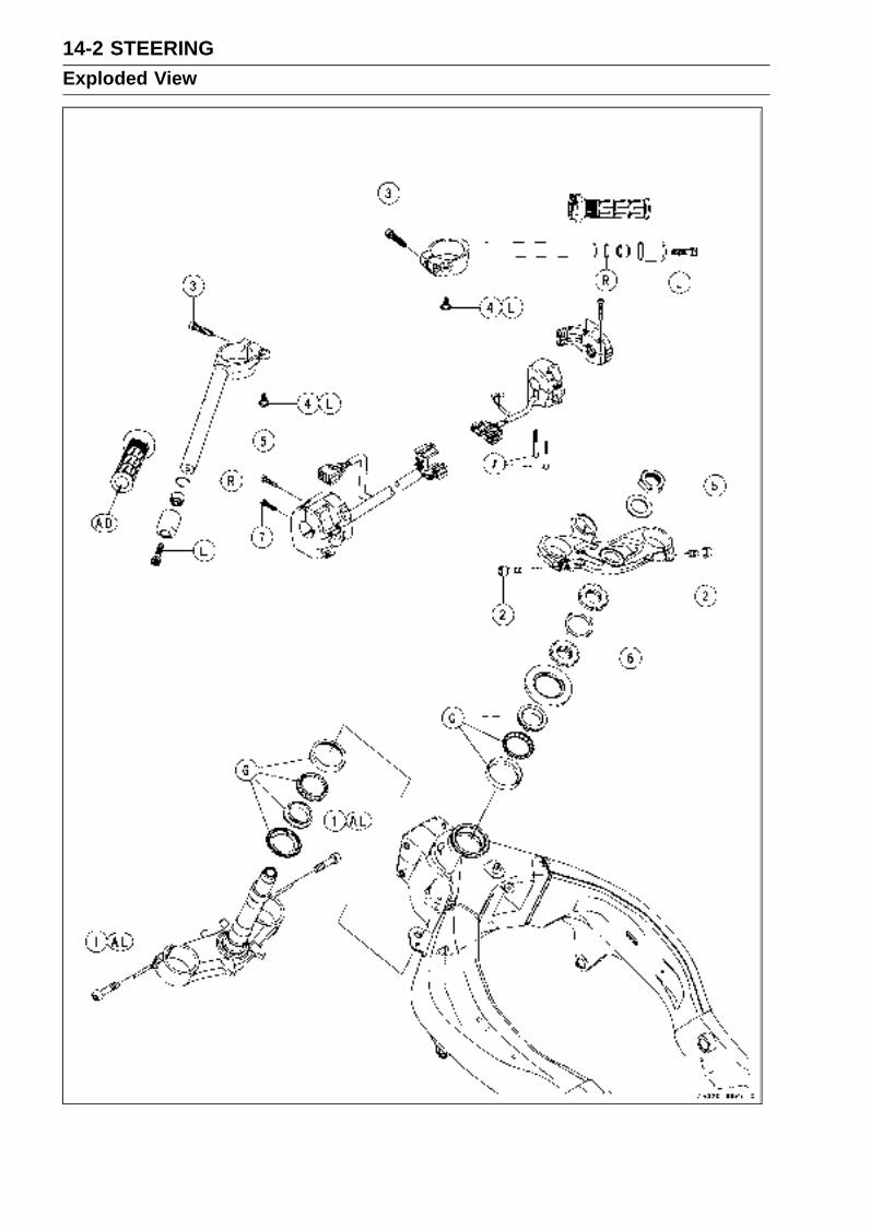
14-2 STEERINGExploded View
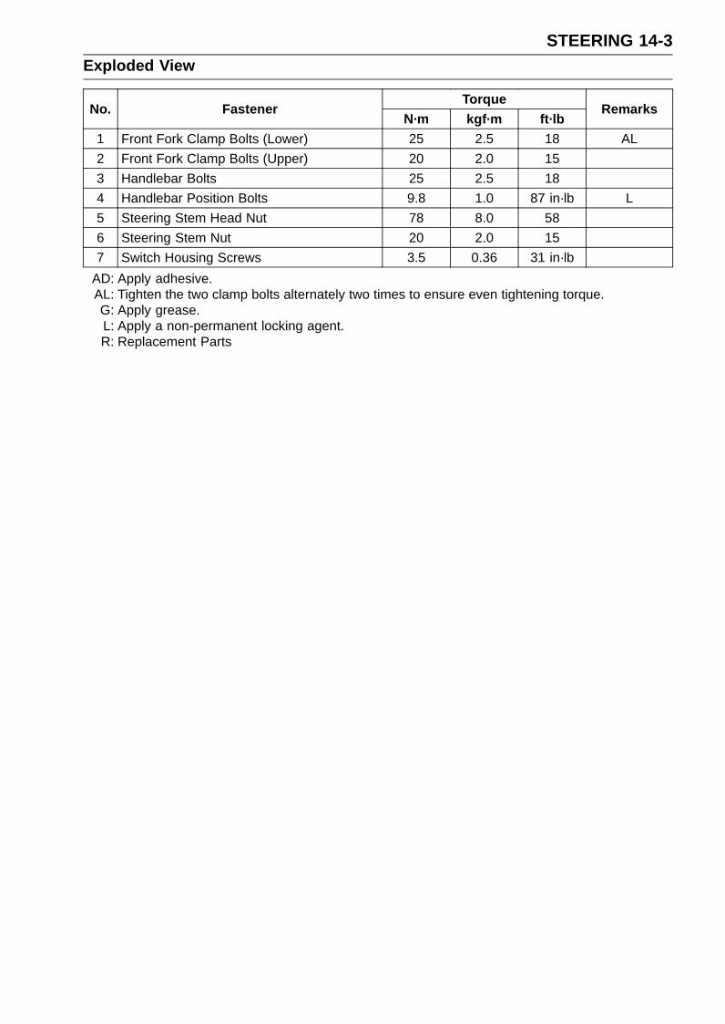
STEERING 14-3Exploded View
TorqueNo. Fastener
N·m kgf·m ft·lbRemarks
1 Front Fork Clamp Bolts (Lower) 25 2.5 18 AL
2 Front Fork Clamp Bolts (Upper) 20 2.0 15
3 Handlebar Bolts 25 2.5 18
4 Handlebar Position Bolts 9.8 1.0 87 in·lb L
5 Steering Stem Head Nut 78 8.0 58
6 Steering Stem Nut 20 2.0 15
7 Switch Housing Screws 3.5 0.36 31 in·lb
AD: Apply adhesive.AL: Tighten the two clamp bolts alternately two times to ensure even tightening torque.G: Apply grease.L: Apply a non-permanent locking agent.R: Replacement Parts
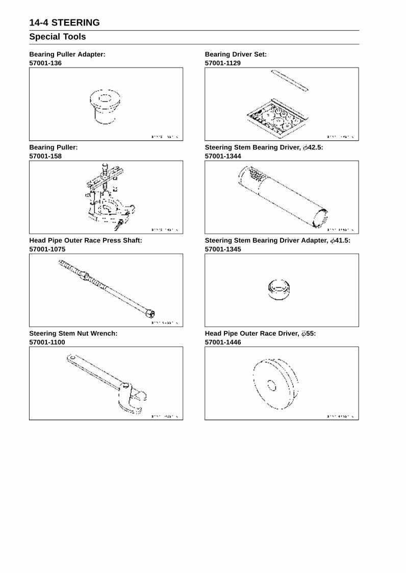
14-4 STEERINGSpecial Tools
Bearing Puller Adapter:57001-136
Bearing Puller:57001-158
Head Pipe Outer Race Press Shaft:57001-1075
Steering Stem Nut Wrench:57001-1100
Bearing Driver Set:57001-1129
Steering Stem Bearing Driver, 42.5:57001-1344
Steering Stem Bearing Driver Adapter, 41.5:57001-1345
Head Pipe Outer Race Driver, 55:57001-1446

STEERING 14-5Steering
Steering Inspection•Refer to the Steering Inspection in the Periodic Mainte-
nance chapter.
Steering Adjustment•Refer to the Steering Adjustment in the Periodic Mainte-
nance chapter.

14-6 STEERINGSteering Stem
Stem, Stem Bearing Removal•Remove:
Upper Fairing (see Upper Fairing Removal in the Framechapter)Front Wheel (see Front Wheel Removal in theWheels/Tires chapter)Front Fork (see Front Fork Removal in the Suspensionchapter)Brake Hose Clamp Bolt [A]
•Remove:Steering Stem Head Nut [A] and Washer [B]Steering Stem HeadHandlebars (see Handlebar Removal in this chapter)
• Bend the claws [A] of lock washer straighten.
•Remove the steering stem locknut [B].Special Tool - Steering Stem Nut Wrench: 57001-1100
•Remove the lock washer.
• Pushing up the stem base, and remove the steering stemnut [A] with stem cap.Special Tool - Steering Stem Nut Wrench [B]: 57001-1100
•Remove:Steering Stem [C]Upper Ball Bearing Inner Race
• To remove the bearing outer races [A] pressed into thehead pipe [B], insert a bar [C] into the recesses [D] of headpipe, and applying it to both recess alternately hammer itto drive the race out.
NOTEIf either steering stem bearing is damaged, it is recom-
mended that both the upper and lower bearings (includ-ing outer races) should be replaced with new ones.

STEERING 14-7Steering Stem
•Remove the lower bearing inner race (with its oil seal)[A] which is pressed onto the steering stem [B] with thebearing puller [C] and adapter [D].
Special Tools - Bearing Puller Adapter: 57001-136Bearing Puller: 57001-158
Stem, Stem Bearing Installation•Replace the bearing outer races with new ones.
•Drive them into the head pipe at the same time.Special Tools - Head Pipe Outer Race Press Shaft [A]:
57001-1075Bearing Driver Set: 57001-1129Head Pipe Outer Race Driver, 55 [B]: 57001
-1446
•Apply grease to the outer races.
•Replace the bearing inner races and oil seal with newones.
• Install the oil seal [D] on the steering stem, and drive thelower ball bearing inner race [A] applied the grease ontothe stem.
Special Tools - Steering Stem Bearing Driver, 42.5 [B]:57001-1344
Steering Stem Bearing Driver Adapter,41.5 [C]: 57001-1345
• Install the lower ball bearing [A] onto the stem.
•Apply grease:Inner and Outer RacesLower and Upper Ball Bearings
The lower and upper ball bearings are identical.
• Install the stem [A] through the head pipe and install theball bearing [B] and inner race [C] on it.
• Install:Stem Cap [D]Steering Stem Nut [E]
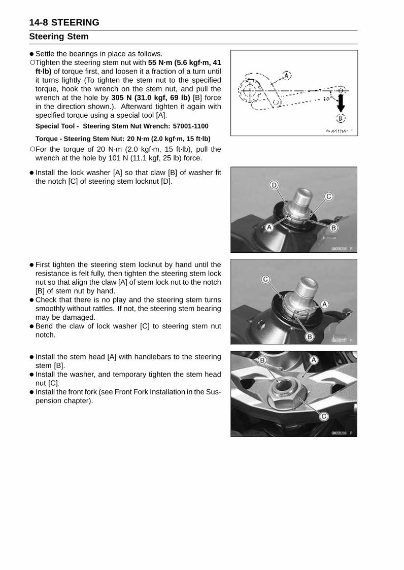
14-8 STEERINGSteering Stem
•Settle the bearings in place as follows.Tighten the steering stem nut with 55 N·m (5.6 kgf·m, 41
ft·lb) of torque first, and loosen it a fraction of a turn untilit turns lightly (To tighten the stem nut to the specifiedtorque, hook the wrench on the stem nut, and pull thewrench at the hole by 305 N (31.0 kgf, 69 lb) [B] forcein the direction shown.). Afterward tighten it again withspecified torque using a special tool [A].Special Tool - Steering Stem Nut Wrench: 57001-1100
Torque - Steering Stem Nut: 20 N·m (2.0 kgf·m, 15 ft·lb)
For the torque of 20 N·m (2.0 kgf·m, 15 ft·lb), pull thewrench at the hole by 101 N (11.1 kgf, 25 lb) force.
• Install the lock washer [A] so that claw [B] of washer fitthe notch [C] of steering stem locknut [D].
• First tighten the steering stem locknut by hand until theresistance is felt fully, then tighten the steering stem locknut so that align the claw [A] of stem lock nut to the notch[B] of stem nut by hand.
•Check that there is no play and the steering stem turnssmoothly without rattles. If not, the steering stem bearingmay be damaged.
• Bend the claw of lock washer [C] to steering stem nutnotch.
• Install the stem head [A] with handlebars to the steeringstem [B].
• Install the washer, and temporary tighten the stem headnut [C].
• Install the front fork (see Front Fork Installation in the Sus-pension chapter).
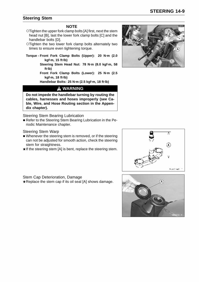
STEERING 14-9Steering Stem
NOTETighten the upper fork clamp bolts [A] first, next the stem
head nut [B], last the lower fork clamp bolts [C] and thehandlebar bolts [D].Tighten the two lower fork clamp bolts alternately two
times to ensure even tightening torque.
Torque - Front Fork Clamp Bolts (Upper): 20 N·m (2.0kgf·m, 15 ft·lb)
Steering Stem Head Nut: 78 N·m (8.0 kgf·m, 58ft·lb)
Front Fork Clamp Bolts (Lower): 25 N·m (2.5kgf·m, 18 ft·lb)
Handlebar Bolts: 25 N·m (2.5 kgf·m, 18 ft·lb)
WARNINGDo not impede the handlebar turning by routing thecables, harnesses and hoses improperly (see Ca-ble, Wire, and Hose Routing section in the Appen-dix chapter).
Steering Stem Bearing Lubrication•Refer to the Steering Stem Bearing Lubrication in the Pe-
riodic Maintenance chapter.
Steering Stem Warp•Whenever the steering stem is removed, or if the steering
can not be adjusted for smooth action, check the steeringstem for straightness.If the steering stem [A] is bent, replace the steering stem.
Stem Cap Deterioration, DamageReplace the stem cap if its oil seal [A] shows damage.
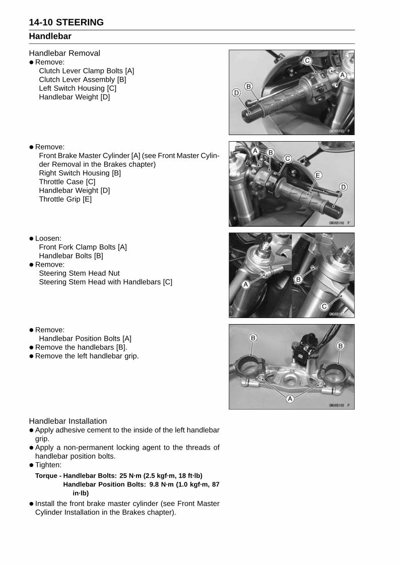
14-10 STEERINGHandlebar
Handlebar Removal•Remove:
Clutch Lever Clamp Bolts [A]Clutch Lever Assembly [B]Left Switch Housing [C]Handlebar Weight [D]
•Remove:Front Brake Master Cylinder [A] (see Front Master Cylin-der Removal in the Brakes chapter)Right Switch Housing [B]Throttle Case [C]Handlebar Weight [D]Throttle Grip [E]
• Loosen:Front Fork Clamp Bolts [A]Handlebar Bolts [B]
•Remove:Steering Stem Head NutSteering Stem Head with Handlebars [C]
•Remove:Handlebar Position Bolts [A]
•Remove the handlebars [B].
• Remove the left handlebar grip.
Handlebar Installation•Apply adhesive cement to the inside of the left handlebar
grip.
• Apply a non-permanent locking agent to the threads ofhandlebar position bolts.
• Tighten:Torque - Handlebar Bolts: 25 N·m (2.5 kgf·m, 18 ft·lb)
Handlebar Position Bolts: 9.8 N·m (1.0 kgf·m, 87in·lb)
• Install the front brake master cylinder (see Front MasterCylinder Installation in the Brakes chapter).
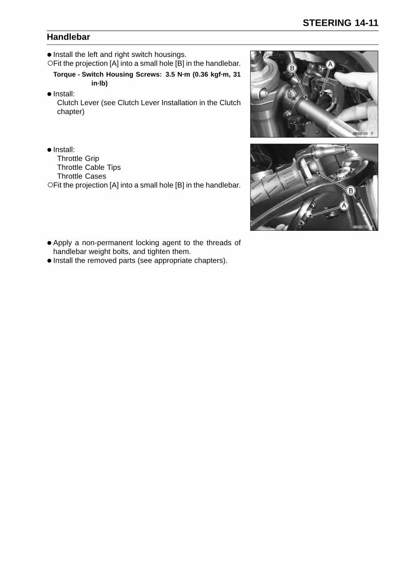
STEERING 14-11Handlebar
• Install the left and right switch housings.Fit the projection [A] into a small hole [B] in the handlebar.
Torque - Switch Housing Screws: 3.5 N·m (0.36 kgf·m, 31in·lb)
• Install:Clutch Lever (see Clutch Lever Installation in the Clutchchapter)
• Install:Throttle GripThrottle Cable TipsThrottle Cases
Fit the projection [A] into a small hole [B] in the handlebar.
• Apply a non-permanent locking agent to the threads ofhandlebar weight bolts, and tighten them.
• Install the removed parts (see appropriate chapters).


FRAME 15-1
15
Frame
Table of Contents
Exploded View........................................................................................................................ 15-2Seats ...................................................................................................................................... 15-8
Rear Seat Removal........................................................................................................... 15-8Rear Seat Installation........................................................................................................ 15-8Front Seat Removal .......................................................................................................... 15-8Front Seat Installation ....................................................................................................... 15-8
Fairings................................................................................................................................... 15-9Lower Fairing Removal ..................................................................................................... 15-9Lower Fairing Installation .................................................................................................. 15-9Center Fairing Removal .................................................................................................... 15-9Center Fairing Installation ................................................................................................. 15-10Windshield Removal ......................................................................................................... 15-10Windshield Installation ...................................................................................................... 15-10Upper Fairing Removal ..................................................................................................... 15-10Upper Fairing Disassembly............................................................................................... 15-11Upper Fairing Assembly.................................................................................................... 15-11Upper Fairing Installation .................................................................................................. 15-12Upper Inner Fairing Removal............................................................................................ 15-12Upper Inner Fairing Installation......................................................................................... 15-12Center Inner Fairing Removal........................................................................................... 15-12Center Inner Fairing Installation........................................................................................ 15-12Right and Left Inner Fairing Removal ............................................................................... 15-13Right and Left Inner Fairing Installation ............................................................................ 15-13
Side Covers ............................................................................................................................ 15-14Left Side Cover Removal .................................................................................................. 15-14Left Side Cover Installation ............................................................................................... 15-14Right Side Cover Removal................................................................................................ 15-14Right Side Cover Installation............................................................................................. 15-14
Seat Cover.............................................................................................................................. 15-15Seat Cover Removal......................................................................................................... 15-15Seat Cover Installation...................................................................................................... 15-15
Fenders .................................................................................................................................. 15-16Front Fender Removal ...................................................................................................... 15-16Front Fender Installation ................................................................................................... 15-16Flap and Rear Fender Rear Removal............................................................................... 15-16Flap and Rear Fender Rear Installation............................................................................ 15-17Rear Fender Front Removal ............................................................................................. 15-18Rear Fender Front Installation .......................................................................................... 15-18
Frame ..................................................................................................................................... 15-19Rear Frame Removal........................................................................................................ 15-19Rear Frame Installation..................................................................................................... 15-19Frame Inspection .............................................................................................................. 15-19
Side Stand.............................................................................................................................. 15-20Side Stand Removal ......................................................................................................... 15-20Side Stand Installation ...................................................................................................... 15-20

15-2 FRAMEExploded View
FRAME 15-3Exploded View
TorqueNo. Fastener
N·m kgf·m ft·lbRemarks
1 Front Footpeg Bracket Bolts 25 2.5 18
2 Rear Footpeg Bracket Bolts 25 2.5 18
3 Rear Frame Bolts 59 6.0 44 L (2)
4 Side Stand Bolt 44 4.5 32 G
5 Side Stand Bracket Bolts 49 5.0 36 L
6 Side Stand Switch Bolt 8.8 0.90 78 in·lb L
7 Side Stand Switch Bracket Bolt 3.9 0.40 35 L
G: Apply grease.L: Apply a non-permanent locking agent.R: Replacement Parts
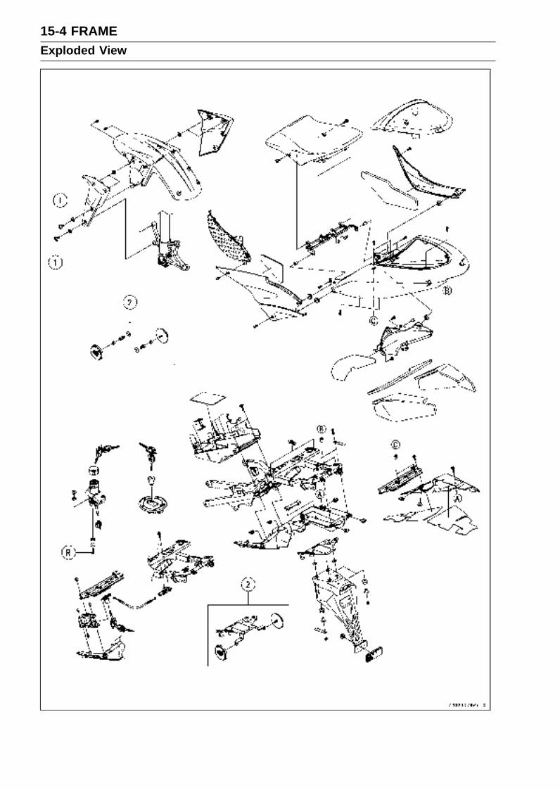
15-4 FRAMEExploded View

FRAME 15-5Exploded View
TorqueNo. Fastener
N·m kgf·m ft·lbRemarks
1 Front Fender Mounting Bolts 3.9 0.40 35 in·lb
2. United States and Canada ModelsR: Replacement Parts
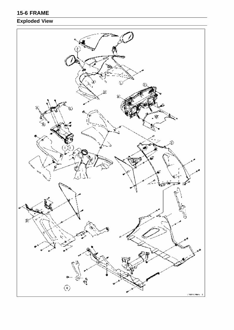
15-6 FRAMEExploded View
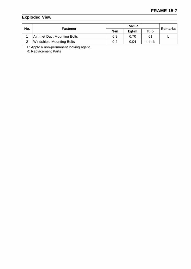
FRAME 15-7Exploded View
TorqueNo. Fastener
N·m kgf·m ft·lbRemarks
1 Air Inlet Duct Mounting Bolts 6.9 0.70 61 L
2 Windshield Mounting Bolts 0.4 0.04 4 in·lb
L: Apply a non-permanent locking agent.R: Replacement Parts
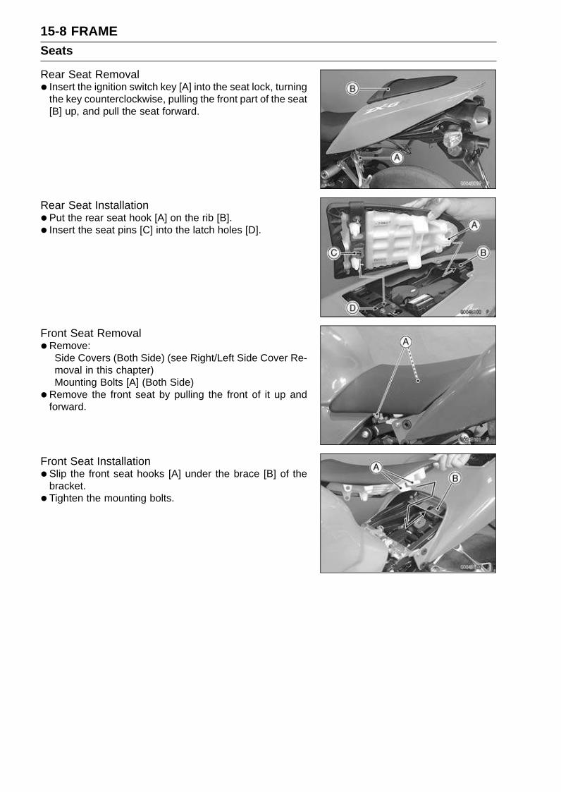
15-8 FRAMESeats
Rear Seat Removal• Insert the ignition switch key [A] into the seat lock, turning
the key counterclockwise, pulling the front part of the seat[B] up, and pull the seat forward.
Rear Seat Installation•Put the rear seat hook [A] on the rib [B].
• Insert the seat pins [C] into the latch holes [D].
Front Seat Removal•Remove:
Side Covers (Both Side) (see Right/Left Side Cover Re-moval in this chapter)Mounting Bolts [A] (Both Side)
•Remove the front seat by pulling the front of it up andforward.
Front Seat Installation•Slip the front seat hooks [A] under the brace [B] of the
bracket.
• Tighten the mounting bolts.
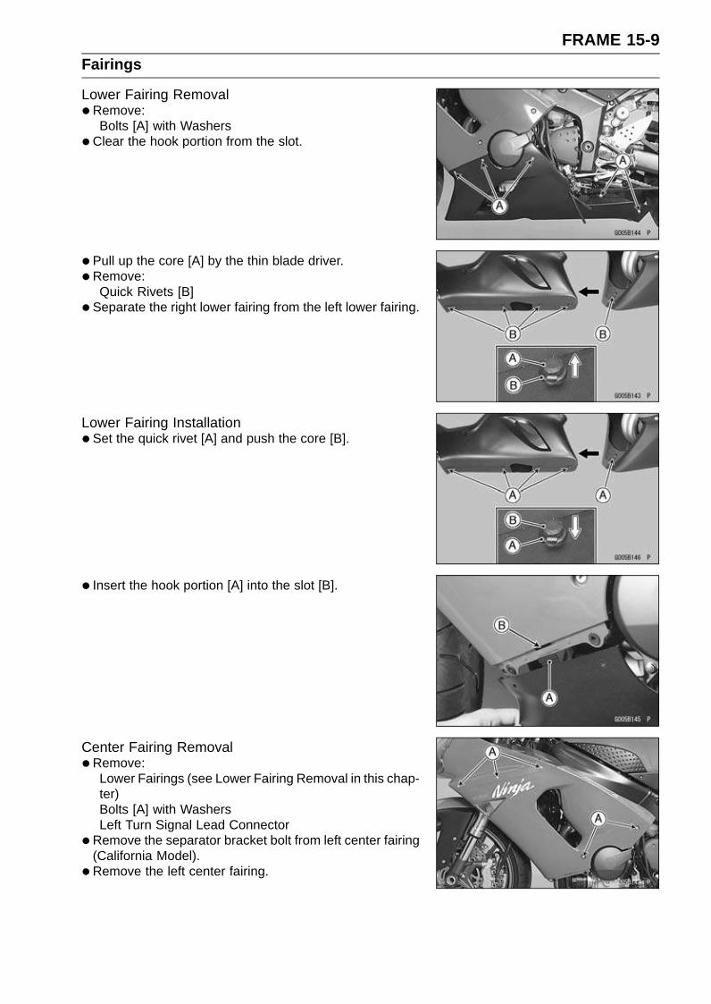
FRAME 15-9Fairings
Lower Fairing Removal•Remove:
Bolts [A] with Washers
•Clear the hook portion from the slot.
• Pull up the core [A] by the thin blade driver.
• Remove:Quick Rivets [B]
• Separate the right lower fairing from the left lower fairing.
Lower Fairing Installation•Set the quick rivet [A] and push the core [B].
• Insert the hook portion [A] into the slot [B].
Center Fairing Removal•Remove:
Lower Fairings (see Lower Fairing Removal in this chap-ter)Bolts [A] with WashersLeft Turn Signal Lead Connector
•Remove the separator bracket bolt from left center fairing(California Model).
• Remove the left center fairing.
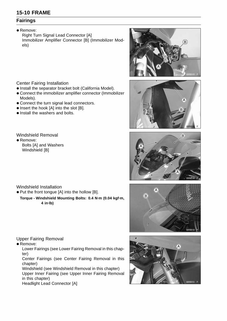
15-10 FRAMEFairings
•Remove:Right Turn Signal Lead Connector [A]Immobilizer Amplifier Connector [B] (Immobilizer Mod-els)
Center Fairing Installation• Install the separator bracket bolt (California Model).
• Connect the immobilizer amplifier connector (ImmobilizerModels).
• Connect the turn signal lead connectors.
• Insert the hook [A] into the slot [B].
• Install the washers and bolts.
Windshield Removal•Remove:
Bolts [A] and WashersWindshield [B]
Windshield Installation•Put the front tongue [A] into the hollow [B].
Torque - Windshield Mounting Bolts: 0.4 N·m (0.04 kgf·m,4 in·lb)
Upper Fairing Removal•Remove:
Lower Fairings (see Lower Fairing Removal in this chap-ter)Center Fairings (see Center Fairing Removal in thischapter)Windshield (see Windshield Removal in this chapter)Upper Inner Fairing (see Upper Inner Fairing Removalin this chapter)Headlight Lead Connector [A]
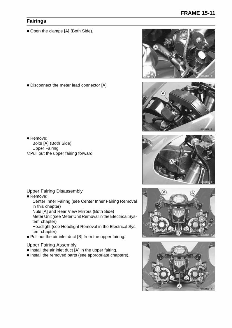
FRAME 15-11Fairings
•Open the clamps [A] (Both Side).
• Disconnect the meter lead connector [A].
• Remove:Bolts [A] (Both Side)Upper Fairing
Pull out the upper fairing forward.
Upper Fairing Disassembly•Remove:
Center Inner Fairing (see Center Inner Fairing Removalin this chapter)Nuts [A] and Rear View Mirrors (Both Side)Meter Unit (see Meter Unit Removal in the Electrical Sys-tem chapter)Headlight (see Headlight Removal in the Electrical Sys-tem chapter)
• Pull out the air inlet duct [B] from the upper fairing.
Upper Fairing Assembly• Install the air inlet duct [A] in the upper fairing.
• Install the removed parts (see appropriate chapters).
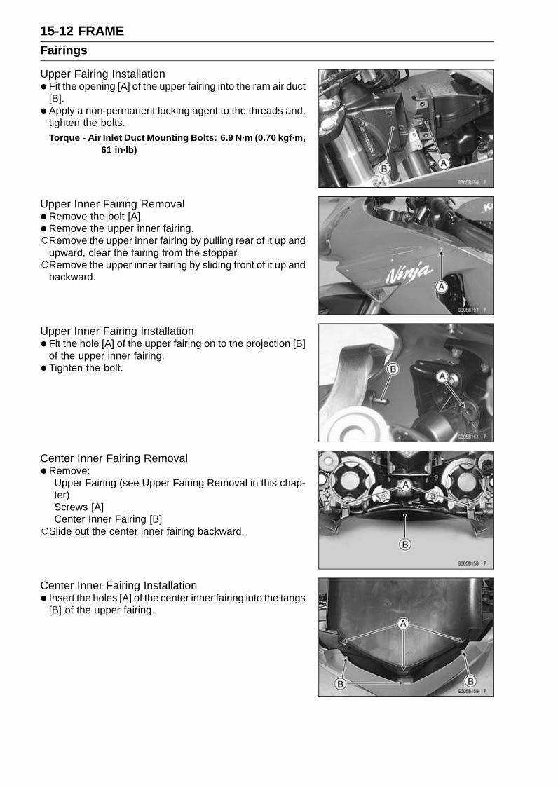
15-12 FRAMEFairings
Upper Fairing Installation•Fit the opening [A] of the upper fairing into the ram air duct
[B].
• Apply a non-permanent locking agent to the threads and,tighten the bolts.Torque - Air Inlet Duct Mounting Bolts: 6.9 N·m (0.70 kgf·m,
61 in·lb)
Upper Inner Fairing Removal•Remove the bolt [A].
• Remove the upper inner fairing.Remove the upper inner fairing by pulling rear of it up and
upward, clear the fairing from the stopper.Remove the upper inner fairing by sliding front of it up and
backward.
Upper Inner Fairing Installation•Fit the hole [A] of the upper fairing on to the projection [B]
of the upper inner fairing.
• Tighten the bolt.
Center Inner Fairing Removal•Remove:
Upper Fairing (see Upper Fairing Removal in this chap-ter)Screws [A]Center Inner Fairing [B]
Slide out the center inner fairing backward.
Center Inner Fairing Installation• Insert the holes [A] of the center inner fairing into the tangs
[B] of the upper fairing.
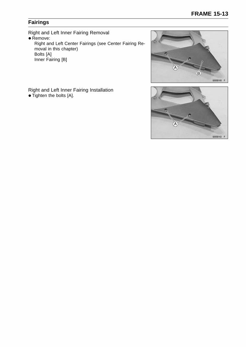
FRAME 15-13Fairings
Right and Left Inner Fairing Removal•Remove:
Right and Left Center Fairings (see Center Fairing Re-moval in this chapter)Bolts [A]Inner Fairing [B]
Right and Left Inner Fairing Installation•Tighten the bolts [A].
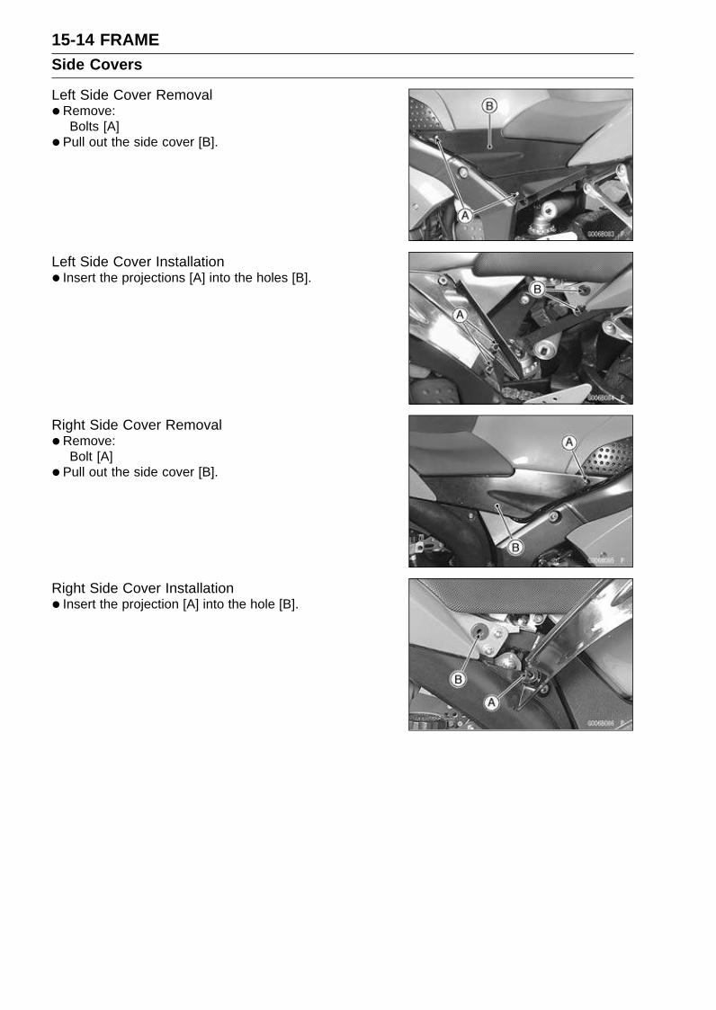
15-14 FRAMESide Covers
Left Side Cover Removal•Remove:
Bolts [A]
• Pull out the side cover [B].
Left Side Cover Installation• Insert the projections [A] into the holes [B].
Right Side Cover Removal•Remove:
Bolt [A]
• Pull out the side cover [B].
Right Side Cover Installation• Insert the projection [A] into the hole [B].

FRAME 15-15Seat Cover
Seat Cover Removal•Remove:
Seats (see Rear/Front Seat Removal in this chapter)Bolts [A]
•Remove:Rivet Screws [A]
• Pull the seat cover backward, and clear the stoppers.
•Disconnect:Tail/Brake Light Connector [A]
•Remove:Bolts [A]Tail/Brake Light [B]
Seat Cover Installation• Install the tail/brake light.
• Insert the projections [A] into the holes [B].
• Connect the tail/brake light connector.
• Install:BoltsRivet Screws
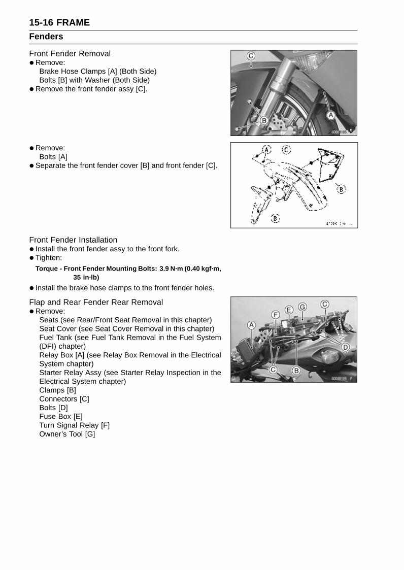
15-16 FRAMEFenders
Front Fender Removal•Remove:
Brake Hose Clamps [A] (Both Side)Bolts [B] with Washer (Both Side)
•Remove the front fender assy [C].
• Remove:Bolts [A]
• Separate the front fender cover [B] and front fender [C].
Front Fender Installation• Install the front fender assy to the front fork.
• Tighten:Torque - Front Fender Mounting Bolts: 3.9 N·m (0.40 kgf·m,
35 in·lb)
• Install the brake hose clamps to the front fender holes.
Flap and Rear Fender Rear Removal•Remove:
Seats (see Rear/Front Seat Removal in this chapter)Seat Cover (see Seat Cover Removal in this chapter)Fuel Tank (see Fuel Tank Removal in the Fuel System(DFI) chapter)Relay Box [A] (see Relay Box Removal in the ElectricalSystem chapter)Starter Relay Assy (see Starter Relay Inspection in theElectrical System chapter)Clamps [B]Connectors [C]Bolts [D]Fuse Box [E]Turn Signal Relay [F]Owner’s Tool [G]
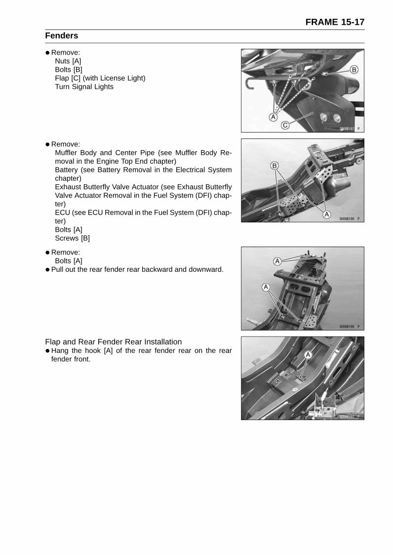
FRAME 15-17Fenders
•Remove:Nuts [A]Bolts [B]Flap [C] (with License Light)Turn Signal Lights
•Remove:Muffler Body and Center Pipe (see Muffler Body Re-moval in the Engine Top End chapter)Battery (see Battery Removal in the Electrical Systemchapter)Exhaust Butterfly Valve Actuator (see Exhaust ButterflyValve Actuator Removal in the Fuel System (DFI) chap-ter)ECU (see ECU Removal in the Fuel System (DFI) chap-ter)Bolts [A]Screws [B]
•Remove:Bolts [A]
• Pull out the rear fender rear backward and downward.
Flap and Rear Fender Rear Installation•Hang the hook [A] of the rear fender rear on the rear
fender front.
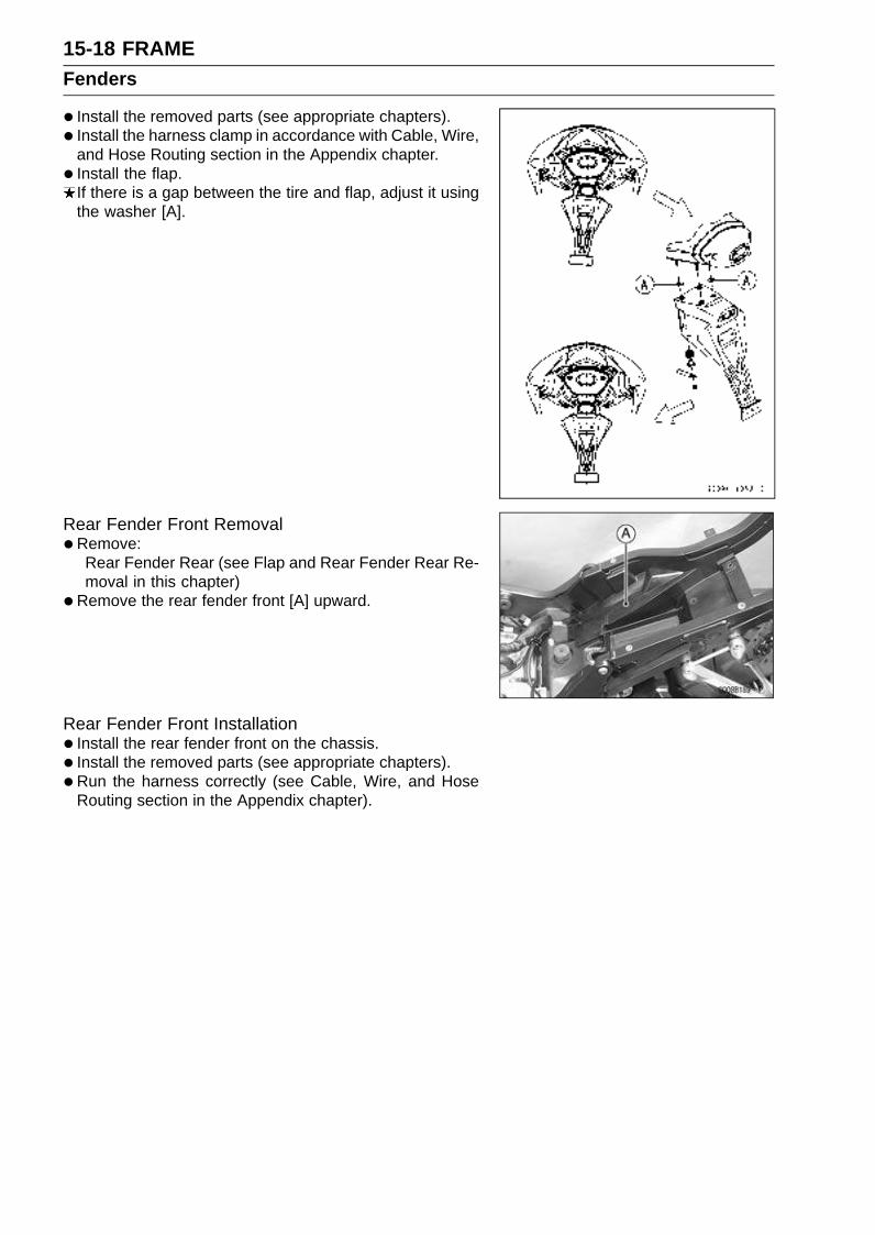
15-18 FRAMEFenders
• Install the removed parts (see appropriate chapters).
• Install the harness clamp in accordance with Cable, Wire,and Hose Routing section in the Appendix chapter.
• Install the flap.If there is a gap between the tire and flap, adjust it usingthe washer [A].
Rear Fender Front Removal•Remove:
Rear Fender Rear (see Flap and Rear Fender Rear Re-moval in this chapter)
•Remove the rear fender front [A] upward.
Rear Fender Front Installation• Install the rear fender front on the chassis.
• Install the removed parts (see appropriate chapters).
• Run the harness correctly (see Cable, Wire, and HoseRouting section in the Appendix chapter).
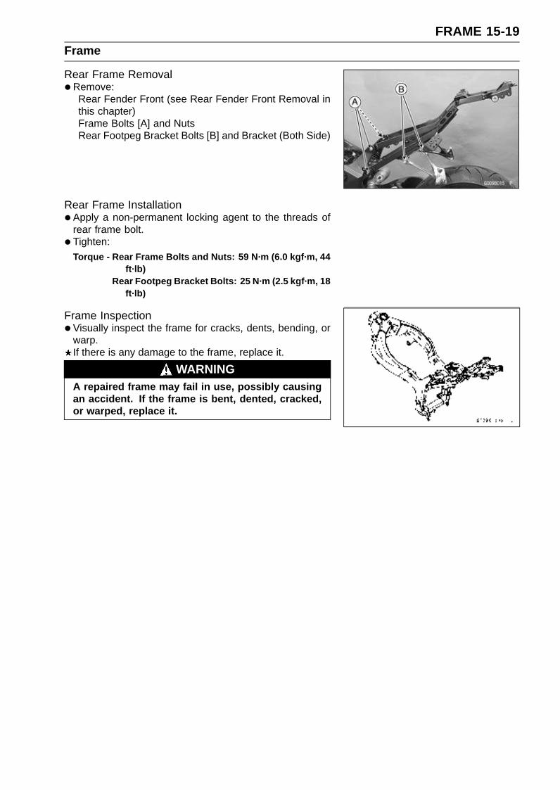
FRAME 15-19Frame
Rear Frame Removal•Remove:
Rear Fender Front (see Rear Fender Front Removal inthis chapter)Frame Bolts [A] and NutsRear Footpeg Bracket Bolts [B] and Bracket (Both Side)
Rear Frame Installation•Apply a non-permanent locking agent to the threads of
rear frame bolt.
• Tighten:
Torque - Rear Frame Bolts and Nuts: 59 N·m (6.0 kgf·m, 44ft·lb)
Rear Footpeg Bracket Bolts: 25 N·m (2.5 kgf·m, 18ft·lb)
Frame Inspection•Visually inspect the frame for cracks, dents, bending, or
warp.If there is any damage to the frame, replace it.
WARNINGA repaired frame may fail in use, possibly causingan accident. If the frame is bent, dented, cracked,or warped, replace it.
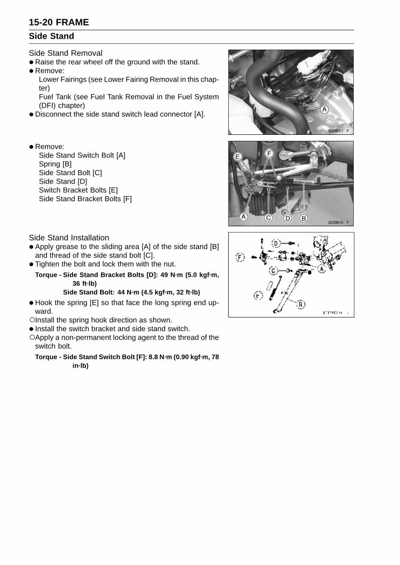
15-20 FRAMESide Stand
Side Stand Removal•Raise the rear wheel off the ground with the stand.
•Remove:Lower Fairings (see Lower Fairing Removal in this chap-ter)Fuel Tank (see Fuel Tank Removal in the Fuel System(DFI) chapter)
•Disconnect the side stand switch lead connector [A].
• Remove:Side Stand Switch Bolt [A]Spring [B]Side Stand Bolt [C]Side Stand [D]Switch Bracket Bolts [E]Side Stand Bracket Bolts [F]
Side Stand Installation•Apply grease to the sliding area [A] of the side stand [B]
and thread of the side stand bolt [C].
• Tighten the bolt and lock them with the nut.Torque - Side Stand Bracket Bolts [D]: 49 N·m (5.0 kgf·m,
36 ft·lb)Side Stand Bolt: 44 N·m (4.5 kgf·m, 32 ft·lb)
•Hook the spring [E] so that face the long spring end up-ward.Install the spring hook direction as shown.
• Install the switch bracket and side stand switch.Apply a non-permanent locking agent to the thread of the
switch bolt.Torque - Side Stand Switch Bolt [F]: 8.8 N·m (0.90 kgf·m, 78
in·lb)
ELECTRICAL SYSTEM 16-1
16
Electrical System
Table of Contents
Parts Location.................................... 16-3Exploded View................................... 16-4Wiring Diagram (United States,
Canada and New Zealand)............. 16-10Wiring Diagram (Other than United
States, Canada, New Zealand,Australia and Malaysia) .................. 16-12
Wiring Diagram (Australia) ................ 16-14Wiring Diagram (Malaysia) ................ 16-16Specifications .................................... 16-18Special Tools and Sealant ................. 16-19Precautions........................................ 16-20Electrical Wiring................................. 16-22
Wiring Inspection ......................... 16-22Battery ............................................... 16-23
Battery Removal .......................... 16-23Battery Installation ....................... 16-23Battery Activation ......................... 16-23Precautions .................................. 16-26Interchange.................................. 16-26Charging Condition Inspection..... 16-27Refreshing Charge....................... 16-27
Charging System............................... 16-29Alternator Cover Removal............ 16-29Alternator Cover Installation......... 16-29Stator Coil Removal ..................... 16-29Stator Coil Installation .................. 16-30Alternator Rotor Removal ............ 16-30Alternator Rotor Installation ......... 16-30Alternator Inspection .................... 16-32Regulator/Rectifier Removal ........ 16-33Regulator/Rectifier Inspection...... 16-33Charging Voltage Inspection ........ 16-35
Starter Motor Clutch .......................... 16-37Starter Motor Clutch
Removal/Inspection................... 16-37Starter Motor Clutch Inspection ... 16-37Starter Motor Clutch Disassembly 16-37Starter Motor Clutch Assembly .... 16-37
Ignition System.................................. 16-38Crankshaft Sensor Removal ........ 16-39Crankshaft Sensor Installation ..... 16-40Crankshaft Sensor Inspection...... 16-40Crankshaft Sensor Peak Voltage. 16-40Timing Rotor Removal ................. 16-41Timing Rotor Installation .............. 16-41
Stick Coil (Ignition Coil togetherwith Spark Plug Cap) Removal . 16-41
Stick Coil (Ignition Coil togetherwith Spark Plug Cap)Installation ................................. 16-42
Stick Coil (Ignition Coil togetherwith Spark Plug Cap) Inspection 16-42
Stick Coil Primary Peak Voltage .. 16-43Spark Plug Removal .................... 16-43Spark Plug Installation ................. 16-44Spark Plug Clean and Inspection. 16-44Spark Plug Gap Inspection .......... 16-44Camshaft Position Sensor
Removal .................................... 16-44Camshaft Position Sensor
Installation ................................. 16-44Camshaft Position Sensor
Inspection.................................. 16-44Camshaft Position Sensor Peak
Voltage Inspection..................... 16-45Interlock Operation Inspection ..... 16-46IC Igniter Inspection ..................... 16-47
Electric Starter System...................... 16-49Starter Motor Removal................. 16-49Starter Motor Installation.............. 16-49Starter Motor Disassembly........... 16-49Starter Motor Assembly ............... 16-49Brush Inspection .......................... 16-50Commutator Cleaning and
Inspection.................................. 16-51Armature Inspection..................... 16-51Brush Lead Inspection ................. 16-51Right-hand End Cover Assembly
Inspection.................................. 16-52Starter Relay Inspection............... 16-52
Lighting System................................. 16-54Headlight Beam Horizontal
Adjustment ................................ 16-54Headlight Beam Vertical
Adjustment ................................ 16-54Headlight Bulb Replacement ....... 16-54City Light Bulb Replacement........ 16-55Headlight Removal/Installation .... 16-55Tail/Brake Light (LED) Removal... 16-56Tail/Brake Light (LED) Installation 16-56
16-2 ELECTRICAL SYSTEM
License Plate Light BulbReplacement ............................. 16-56
Turn Signal Light BulbReplacement ............................. 16-58
Turn Signal Relay Inspection ....... 16-59Radiator Fan System......................... 16-62
Fan Motor Inspection ................... 16-62Meter, Gauge, Indicator Unit.............. 16-64
Meter Unit Removal ..................... 16-64Meter Unit Disassembly ............... 16-64Electronic Combination Meter
Assembly Inspection ................. 16-65Immobilizer System (Equipped
Models) ........................................... 16-74Operational Cautions ................... 16-74Key Registration........................... 16-74Immobilizer System Parts
Replacement ............................. 16-90Immobilizer System Inspection .... 16-92
Switches and Sensors....................... 16-93
Brake Light Timing Inspection...... 16-93Brake Light Timing Adjustment .... 16-93Neutral Switch Replacement........ 16-93Switch Inspection ......................... 16-94Water Temperature Sensor
Inspection.................................. 16-95Speed Sensor Removal ............... 16-95Speed Sensor Installation ............ 16-95Speed Sensor Inspection............. 16-96Fuel Reserve Switch Inspection... 16-96
Relay Box .......................................... 16-97Relay Box Removal ..................... 16-97Relay Circuit Inspection ............... 16-97Diode Circuit Inspection ............... 16-98
Fuse................................................... 16-10030 A Main Fuse Removal............. 16-100Fuse Box Fuse Removal.............. 16-10015 A ECU Fuse Removal............. 16-100Fuse Installation........................... 16-101Fuse Inspection............................ 16-101

ELECTRICAL SYSTEM 16-3Parts Location
1. Starter Lockout Switch2. Ignition Switch with Immobilizer Antenna3. Stick Coils4. Water Temperature Sensor5. Alternator6. Starter Relay with Main Fuse7. Battery 12 V 8 Ah8. Relay Box9. ECU (Electric Control Unit)
10. Fuse Box with ECU Main Fuse11. Camshaft Position Sensor
12. Starter Motor13. Speed Sensor14. Side Stand Switch15. Neutral Switch16. Turn Signal Relay17. Regulator/rectifier18. Front Brake Light Switch19. Meter Unit20. Rear Brake Light Switch21. Crankshaft Sensor
Immobilizer Amplifier (Right Center Fairing Side)
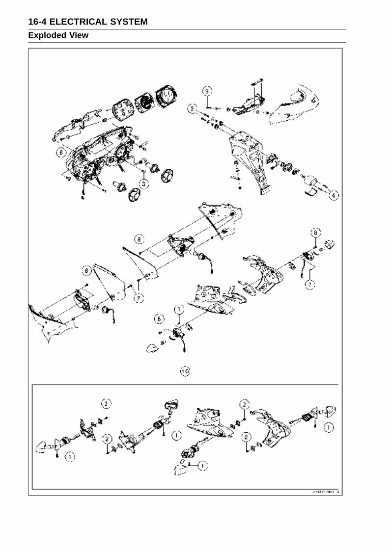
16-4 ELECTRICAL SYSTEMExploded View

ELECTRICAL SYSTEM 16-5Exploded View
TorqueNo. Fastener
N·m kgf·m ft·lbRemarks
1 Front Turn Signal Light Lens Screws 1.0 0.10 9 in·lb
2 Front Turn Signal Light Mounting Screws 1.2 0.12 10 in·lb
3 Headlight Mounting Screws 1.2 0.12 10 in·lb
4 Licence Light Assembly Screws 0.9 0.09 8 in·lb
5 Licence Light Mounting Screws 1.2 0.12 10 in·lb
6 Meter Mounting Screws 1.2 0.12 10 in·lb
7 Rear Turn Signal Light Lens Screws 1.0 0.10 9 in·lb
8 Rear Turn Signal Light Mounting Screws 1.2 0.12 10 in·lb
9 Tail/Brake Light Mounting Screws 4.0 0.40 35 in·lb
10. United States and Canada Models

16-6 ELECTRICAL SYSTEMExploded View

ELECTRICAL SYSTEM 16-7Exploded View
TorqueNo. Fastener
N·m kgf·m ft·lbRemarks
1 Front Brake Light Switch Screw 1.2 0.12 10 in·lb
2 Starter Motor Clutch Bolts 34 3.5 25 L
3 Starter Motor Mounting Bolts 11 1.1 97 in·lb
4 Starter Motor Cable Terminal Bolt 2.7 0.28 24 in·lb
5 Starter Relay Cable Terminal Bolts 3.9 0.40 35 in·lb
6 Switch Housing Screws 3.5 0.36 31 in·lb
7. ECU Main Fuse8. Fuse Box9. Immobilizer ModelsG: Apply grease.M: Apply molybdenum disulfide grease.R: Replacement Parts

16-8 ELECTRICAL SYSTEMExploded View
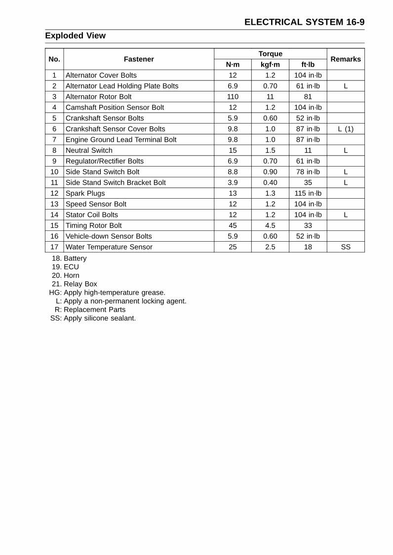
ELECTRICAL SYSTEM 16-9Exploded View
TorqueNo. Fastener
N·m kgf·m ft·lbRemarks
1 Alternator Cover Bolts 12 1.2 104 in·lb
2 Alternator Lead Holding Plate Bolts 6.9 0.70 61 in·lb L
3 Alternator Rotor Bolt 110 11 81
4 Camshaft Position Sensor Bolt 12 1.2 104 in·lb
5 Crankshaft Sensor Bolts 5.9 0.60 52 in·lb
6 Crankshaft Sensor Cover Bolts 9.8 1.0 87 in·lb L (1)
7 Engine Ground Lead Terminal Bolt 9.8 1.0 87 in·lb
8 Neutral Switch 15 1.5 11 L
9 Regulator/Rectifier Bolts 6.9 0.70 61 in·lb
10 Side Stand Switch Bolt 8.8 0.90 78 in·lb L
11 Side Stand Switch Bracket Bolt 3.9 0.40 35 L
12 Spark Plugs 13 1.3 115 in·lb
13 Speed Sensor Bolt 12 1.2 104 in·lb
14 Stator Coil Bolts 12 1.2 104 in·lb L
15 Timing Rotor Bolt 45 4.5 33
16 Vehicle-down Sensor Bolts 5.9 0.60 52 in·lb
17 Water Temperature Sensor 25 2.5 18 SS
18. Battery19. ECU20. Horn21. Relay Box
HG: Apply high-temperature grease.L: Apply a non-permanent locking agent.R: Replacement Parts
SS: Apply silicone sealant.
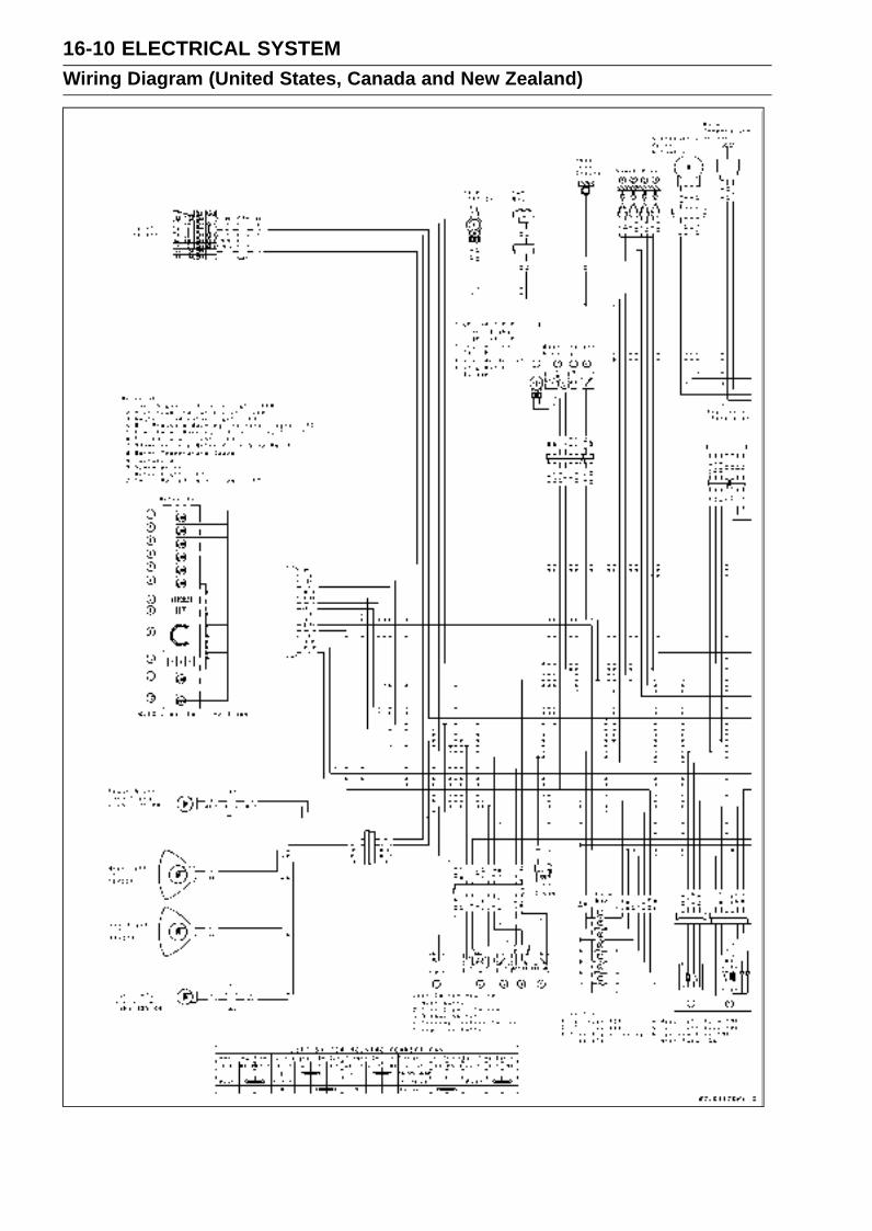
16-10 ELECTRICAL SYSTEMWiring Diagram (United States, Canada and New Zealand)
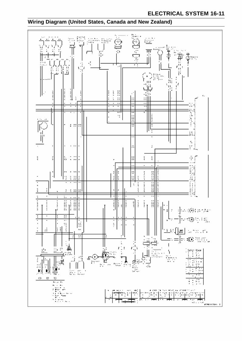
ELECTRICAL SYSTEM 16-11Wiring Diagram (United States, Canada and New Zealand)
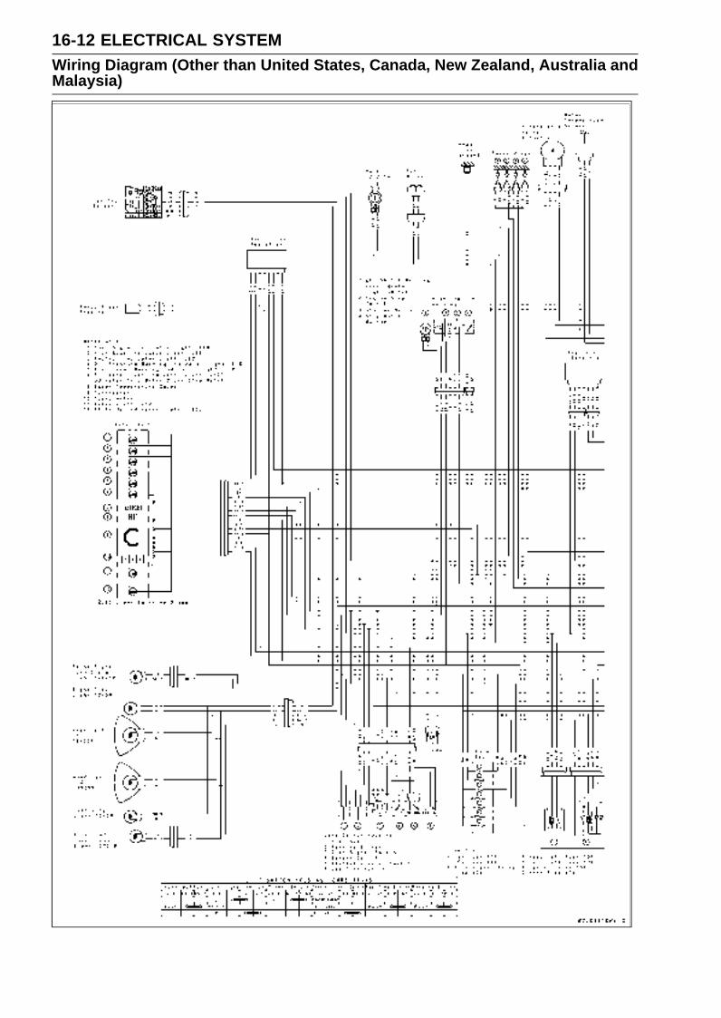
16-12 ELECTRICAL SYSTEMWiring Diagram (Other than United States, Canada, New Zealand, Australia andMalaysia)

ELECTRICAL SYSTEM 16-13Wiring Diagram (Other than United States, Canada, New Zealand, Australia andMalaysia)

16-14 ELECTRICAL SYSTEMWiring Diagram (Australia)
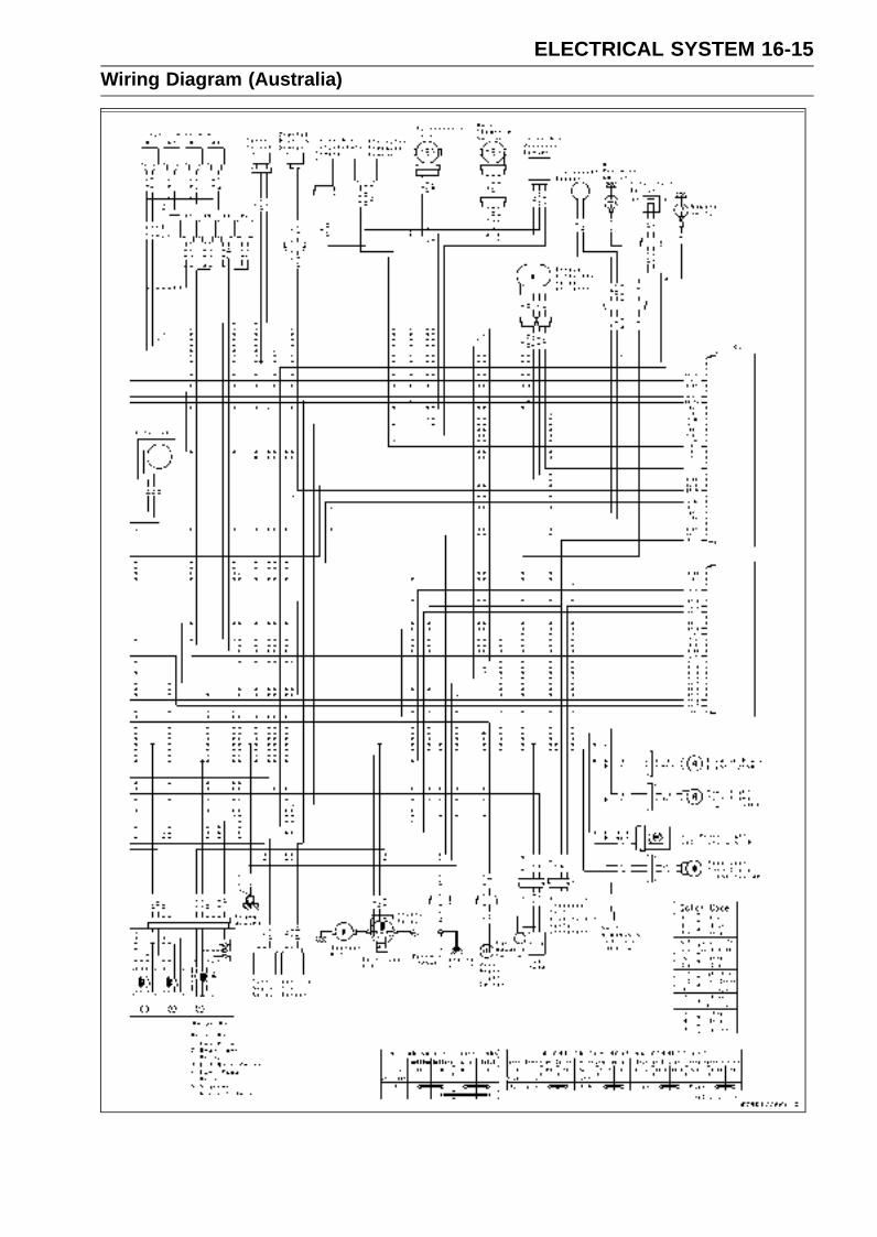
ELECTRICAL SYSTEM 16-15Wiring Diagram (Australia)

16-16 ELECTRICAL SYSTEMWiring Diagram (Malaysia)
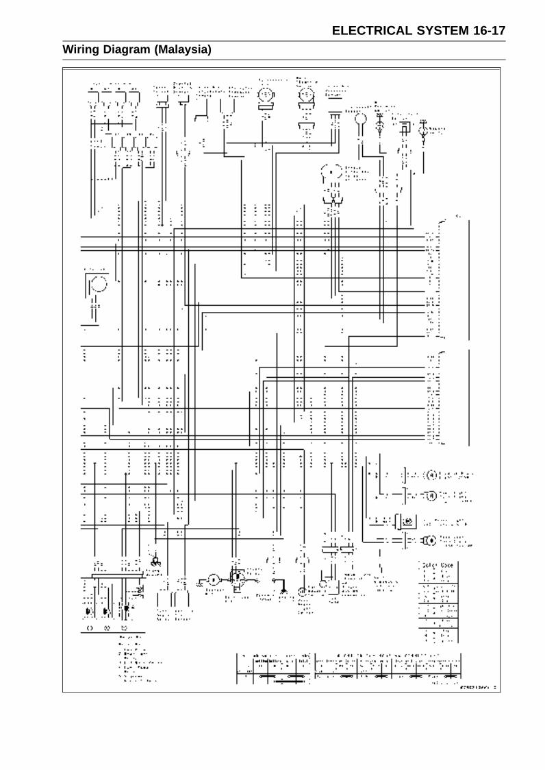
ELECTRICAL SYSTEM 16-17Wiring Diagram (Malaysia)

16-18 ELECTRICAL SYSTEMSpecifications
Item StandardBattery
Type Sealed battery
Capacity 12 V 8 Ah
Voltage 12.8 V or more
Charging SystemType Three-phase AC
Alternator Output Voltage 42 V or more @4 000 r/min (rpm)
Stator Coil Resistance 0.3 ∼ 0.4 ΩCharging Voltage (Regulator/rectifierOutput Voltage)
14.2 ∼ 15.2 V
Ignition SystemCrankshaft Sensor Resistance 380 ∼ 570 ΩCrankshaft Sensor Peak Voltage 3.2 V or more
Camshaft Position Sensor Resistance 400 ∼ 460 ΩCamshaft Position Sensor Peak Voltage 0.4 V or more
Spark Plug Gap 0.7 mm ∼ 0.8 mm (0.028 ∼ 0.032 in.)
Stick Coil:
Primary Winding Resistance 1.2 ∼ 1.6 ΩSecondary Winding Resistance 8.5 ∼ 11.5 kΩPrimary Peak Voltage 100 V or more
Electric Starter SystemStarter Motor:
Brush Length 7 mm (0.28 in.), Service Limit: 3.5 mm (0.14 in.)
Commutator Diameter 24 mm (0.94 in.), Service Limit: 23 mm (0.91 in.)
Switch and SensorRear Brake Light Switch Timing ON after about 10 mm (0.39 in.) pedal travel
Engine Oil Pressure Switch Connections When engine is stopped: ONWhen engine is running: OFF
Fan Switch Resistance:
Rising Temperature From OFF to ON @93 ∼ 103°C (199 ∼ 217°F)
Falling Temperature Fan stops with the temperature 3 ∼ 8°C (38 ∼ 46°F)lower than the operation temperature range.ON: Less than 0.5 ΩOFF: More than 10 MΩ
Water Temperature Sensor Resistance In the text
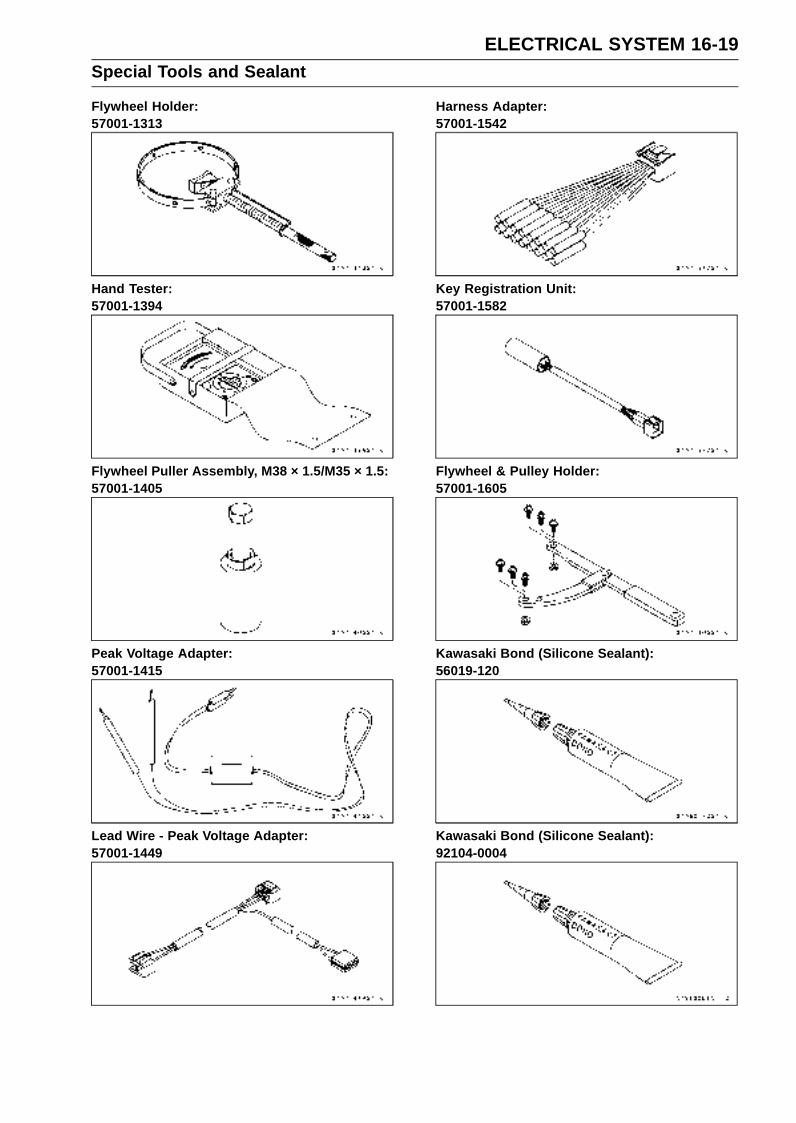
ELECTRICAL SYSTEM 16-19Special Tools and Sealant
Flywheel Holder:57001-1313
Hand Tester:57001-1394
Flywheel Puller Assembly, M38 × 1.5/M35 × 1.5:57001-1405
Peak Voltage Adapter:57001-1415
Lead Wire - Peak Voltage Adapter:57001-1449
Harness Adapter:57001-1542
Key Registration Unit:57001-1582
Flywheel & Pulley Holder:57001-1605
Kawasaki Bond (Silicone Sealant):56019-120
Kawasaki Bond (Silicone Sealant):92104-0004
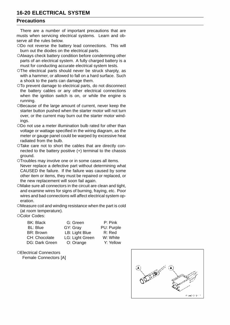
16-20 ELECTRICAL SYSTEMPrecautions
There are a number of important precautions that aremusts when servicing electrical systems. Learn and ob-serve all the rules below.Do not reverse the battery lead connections. This will
burn out the diodes on the electrical parts.Always check battery condition before condemning other
parts of an electrical system. A fully charged battery is amust for conducting accurate electrical system tests.The electrical parts should never be struck sharply, as
with a hammer, or allowed to fall on a hard surface. Sucha shock to the parts can damage them.To prevent damage to electrical parts, do not disconnect
the battery cables or any other electrical connectionswhen the ignition switch is on, or while the engine isrunning.Because of the large amount of current, never keep the
starter button pushed when the starter motor will not turnover, or the current may burn out the starter motor wind-ings.Do not use a meter illumination bulb rated for other than
voltage or wattage specified in the wiring diagram, as themeter or gauge panel could be warped by excessive heatradiated from the bulb.Take care not to short the cables that are directly con-
nected to the battery positive (+) terminal to the chassisground.Troubles may involve one or in some cases all items.
Never replace a defective part without determining whatCAUSED the failure. If the failure was caused by someother item or items, they must be repaired or replaced, orthe new replacement will soon fail again.Make sure all connectors in the circuit are clean and tight,
and examine wires for signs of burning, fraying, etc. Poorwires and bad connections will affect electrical system op-eration.Measure coil and winding resistance when the part is cold
(at room temperature).Color Codes:
BK: BlackBL: BlueBR: BrownCH: ChocolateDG: Dark Green
G: GreenGY: GrayLB: Light BlueLG: Light Green
O: Orange
P: PinkPU: Purple
R: RedW: WhiteY: Yellow
Electrical ConnectorsFemale Connectors [A]
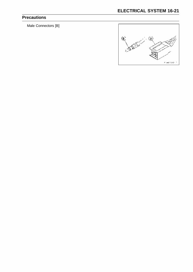
ELECTRICAL SYSTEM 16-21Precautions
Male Connectors [B]

16-22 ELECTRICAL SYSTEMElectrical Wiring
Wiring Inspection•Visually inspect the wiring for signs of burning, fraying,
etc.If any wiring is poor, replace the damaged wiring.
• Pull each connector [A] apart and inspect it for corrosion,dirt, and damage.If the connector is corroded or dirty, clean it carefully. If itis damaged, replace it.
• Check the wiring for continuity.Use the wiring diagram to find the ends of the lead which
is suspected of being a problem.Connect the hand tester between the ends of the leads.
Special Tool - Hand Tester: 57001-1394
Set the tester to the × 1 Ω range, and read the tester.If the tester does not read 0 Ω, the lead is defective. Re-place the lead or the wiring harness [B] if necessary.

ELECTRICAL SYSTEM 16-23Battery
Battery Removal•Remove:
Front Seat (see Front Seat Removal in the Frame chap-ter)Fuel Tank (see Fuel Tank Removal in the Fuel System(DFI) chapter)Bolts [A]Connector [B]Fuel Tank Bracket [C]
• Slide the caps [A].
• Disconnect the negative (–) cable [B] and then positive(+) cable [C].
CAUTION
Be sure to disconnect the negative (–) cable first.
•Remove the battery.
Battery Installation•Visually inspect the surface of the battery container.
If any signs of cracking or electrolyte leakage from thesides of the battery.
• Put the battery into the battery case.
• Install the fuel tank bracket and connector.
• Connect the positive cable [A] (red cap) to the (+) terminalfirst, and then the negative cable [B] to the (–) terminal.
• Apply a light coat of grease on the terminals to preventcorrosion.
•Cover the terminals with the caps [C].
CAUTION
If each battery cable is not correctly disconnectedor connected, sparks can arise at electrical connec-tions, causing damage to electrical and DFI parts.
Battery ActivationElectrolyte Filling
•Make sure that the model name [A] of the electrolyte con-tainer matches the model name [B] of the battery. Thesenames must be the same.
Battery Model Name for ZX636C: YTX9-BS
CAUTION
Be sure to use the electrolyte container with thesame model name as the battery since the elec-trolyte volume and specific gravity vary with thebattery type. This is to prevent overfilling of theelectrolyte, shorting the battery life, and deteriora-tion of the battery performance.
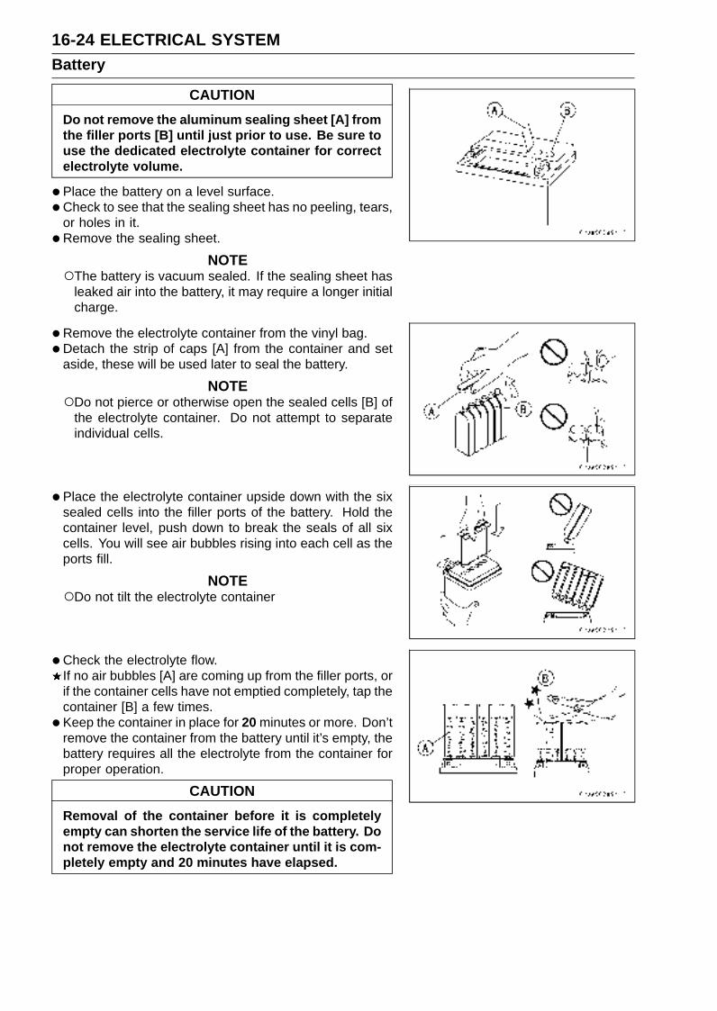
16-24 ELECTRICAL SYSTEMBattery
CAUTION
Do not remove the aluminum sealing sheet [A] fromthe filler ports [B] until just prior to use. Be sure touse the dedicated electrolyte container for correctelectrolyte volume.
•Place the battery on a level surface.
•Check to see that the sealing sheet has no peeling, tears,or holes in it.
• Remove the sealing sheet.
NOTEThe battery is vacuum sealed. If the sealing sheet has
leaked air into the battery, it may require a longer initialcharge.
•Remove the electrolyte container from the vinyl bag.
•Detach the strip of caps [A] from the container and setaside, these will be used later to seal the battery.
NOTEDo not pierce or otherwise open the sealed cells [B] of
the electrolyte container. Do not attempt to separateindividual cells.
•Place the electrolyte container upside down with the sixsealed cells into the filler ports of the battery. Hold thecontainer level, push down to break the seals of all sixcells. You will see air bubbles rising into each cell as theports fill.
NOTEDo not tilt the electrolyte container
•Check the electrolyte flow.If no air bubbles [A] are coming up from the filler ports, orif the container cells have not emptied completely, tap thecontainer [B] a few times.
• Keep the container in place for 20 minutes or more. Don’tremove the container from the battery until it’s empty, thebattery requires all the electrolyte from the container forproper operation.
CAUTION
Removal of the container before it is completelyempty can shorten the service life of the battery. Donot remove the electrolyte container until it is com-pletely empty and 20 minutes have elapsed.
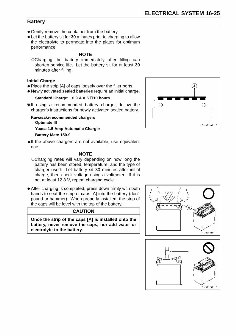
ELECTRICAL SYSTEM 16-25Battery
•Gently remove the container from the battery.
• Let the battery sit for 30 minutes prior to charging to allowthe electrolyte to permeate into the plates for optimumperformance.
NOTECharging the battery immediately after filling can
shorten service life. Let the battery sit for at least 30minutes after filling.
Initial Charge
•Place the strip [A] of caps loosely over the filler ports.
• Newly activated sealed batteries require an initial charge.
Standard Charge: 0.9 A × 5 ∼ 10 hours
If using a recommended battery charger, follow thecharger’s instructions for newly activated sealed battery.
Kawasaki-recommended chargersOptimate III
Yuasa 1.5 Amp Automatic Charger
Battery Mate 150-9
If the above chargers are not available, use equivalentone.
NOTECharging rates will vary depending on how long the
battery has been stored, temperature, and the type ofcharger used. Let battery sit 30 minutes after initialcharge, then check voltage using a voltmeter. If it isnot at least 12.8 V, repeat charging cycle.
•After charging is completed, press down firmly with bothhands to seat the strip of caps [A] into the battery (don’tpound or hammer). When properly installed, the strip ofthe caps will be level with the top of the battery.
CAUTION
Once the strip of the caps [A] is installed onto thebattery, never remove the caps, nor add water orelectrolyte to the battery.
16-26 ELECTRICAL SYSTEMBattery
NOTETo ensure maximum battery life and customer satisfac-
tion, it is recommended the battery be load tested atthree times its amp-hour rating for 15 seconds.Re-check voltage and if less than 12.8 V repeat thecharging cycle and load test. If still below 12.8 V thebattery is defective.
Precautions1) No need of topping-upNo topping-up is necessary in this battery until it ends its life under normal use. Forcibly prying off theseal cap to add water is very dangerous. Never do that.2) Refreshing charge.
If an engine will not start, a horn sounds weak, or lamps are dim, it indicates the battery has beendischarged. Give refresh charge for 5 to 10 hours with charge current shown in the specification(see Specifications in this chapter).
When a fast charge is inevitably required, do it following precisely the maximum charge currentand time conditions indicated on the battery.
CAUTION
This battery is designed to sustain no unusual deterioration if refresh-charged accordingto the method specified above. However, the battery’s performance may be reduced no-ticeably if charged under conditions other than given above. Never remove the seal capduring refresh charge.If by chance an excessive amount of gas is generated due to overcharging, the relief valvereleases the gas to keep the battery normal.
3) When you do not use the motorcycle for months.Give a refresh charge before you store the motorcycle and store it with the negative cable re-
moved. Give a refresh charge once a month during storage.4) Battery life.
If the battery will not start the engine even after several refresh charges, the battery has ex-ceeded its useful life. Replace it (Provided, however, the vehicle’s starting system has no prob-lem).
WARNINGKeep the battery away from sparks and open flames during charging, since the batterygives off an explosive gas mixture of hydrogen and oxygen. When using a battery charger,connect the battery to the charger before turning on the charger.This procedure prevents sparks at the battery terminals which could ignite any batterygases.No fire should be drawn near the battery, or no terminals should have the tightening loos-ened.The electrolyte contains sulfuric acid. Be careful not to have it touch your skin or eyes. Iftouched, wash it off with liberal amount of water. Get medial attention if severe.
InterchangeA sealed battery can fully display its performance only when combined with a proper vehicle electric
system. Therefore, replace a sealed battery only on a motorcycle which was originally equipped witha sealed battery.
Be careful, if a sealed battery is installed on a motorcycle which had an ordinary battery as originalequipment, the sealed battery’s life will be shortened.
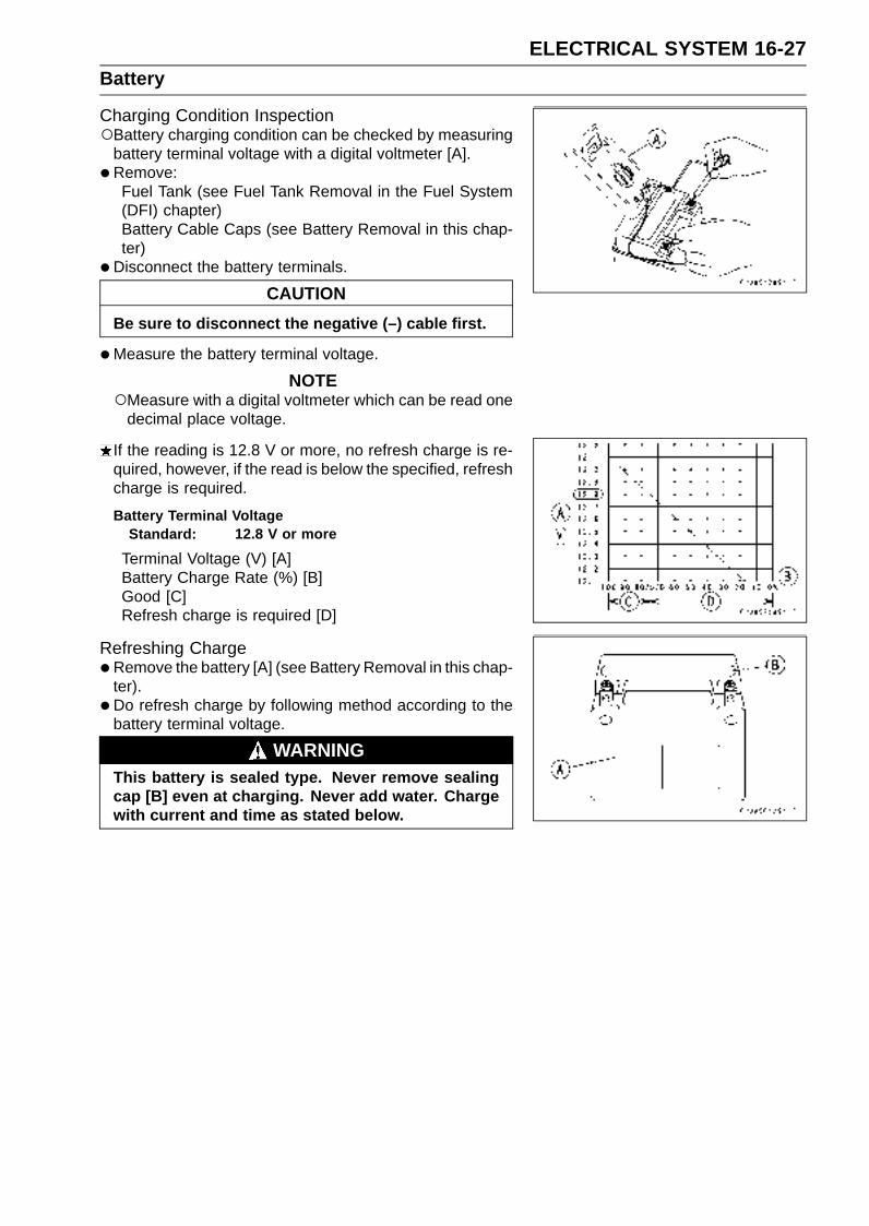
ELECTRICAL SYSTEM 16-27Battery
Charging Condition InspectionBattery charging condition can be checked by measuring
battery terminal voltage with a digital voltmeter [A].
• Remove:Fuel Tank (see Fuel Tank Removal in the Fuel System(DFI) chapter)Battery Cable Caps (see Battery Removal in this chap-ter)
•Disconnect the battery terminals.
CAUTION
Be sure to disconnect the negative (–) cable first.
•Measure the battery terminal voltage.
NOTEMeasure with a digital voltmeter which can be read one
decimal place voltage.
If the reading is 12.8 V or more, no refresh charge is re-quired, however, if the read is below the specified, refreshcharge is required.
Battery Terminal VoltageStandard: 12.8 V or more
Terminal Voltage (V) [A]Battery Charge Rate (%) [B]Good [C]Refresh charge is required [D]
Refreshing Charge•Remove the battery [A] (see Battery Removal in this chap-
ter).
• Do refresh charge by following method according to thebattery terminal voltage.
WARNINGThis battery is sealed type. Never remove sealingcap [B] even at charging. Never add water. Chargewith current and time as stated below.
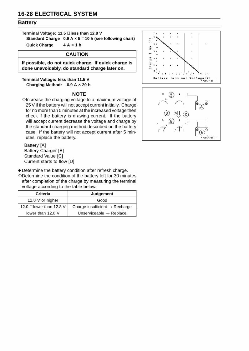
16-28 ELECTRICAL SYSTEMBattery
Terminal Voltage: 11.5 ∼ less than 12.8 VStandard Charge 0.9 A × 5 ∼ 10 h (see following chart)
Quick Charge 4 A × 1 h
CAUTION
If possible, do not quick charge. If quick charge isdone unavoidably, do standard charge later on.
Terminal Voltage: less than 11.5 VCharging Method: 0.9 A × 20 h
NOTEIncrease the charging voltage to a maximum voltage of
25 V if the battery will not accept current initially. Chargefor no more than 5 minutes at the increased voltage thencheck if the battery is drawing current. If the batterywill accept current decrease the voltage and charge bythe standard charging method described on the batterycase. If the battery will not accept current after 5 min-utes, replace the battery.
Battery [A]Battery Charger [B]Standard Value [C]Current starts to flow [D]
•Determine the battery condition after refresh charge.Determine the condition of the battery left for 30 minutes
after completion of the charge by measuring the terminalvoltage according to the table below.
Criteria Judgement
12.8 V or higher Good
12.0 ∼ lower than 12.8 V Charge insufficient → Recharge
lower than 12.0 V Unserviceable → Replace

ELECTRICAL SYSTEM 16-29Charging System
Alternator Cover Removal•Remove:
Left Center Fairing (see Center Fairing Removal in theFrame chapter)Fuel Tank (see Fuel Tank Removal in the Fuel System(DFI) chapter)Coolant Reserve Tank (see Coolant Reserve Tank Re-moval in the Cooling System chapter)Alternator Lead Connector [A]
•Remove:Bolts [A]Cover [B]
Alternator Cover Installation•Apply silicone sealant to the alternator lead grommet and
crankcase halves mating surface [A] on the front and rearsides of the cover mount.Sealant - Kawasaki Bond (Silicone Sealant): 92104-0004
•Check that dowel pins [B] are in place on the crankcase.
• Install a new gasket and the alternator cover.
• Tighten:
Torque - Alternator Cover Bolts: 12 N·m (1.2 kgf·m, 104in·lb)
Stator Coil Removal•Remove:
Alternator Cover (see Alternator Cover Removal in thischapter)Holding Plate Bolts [A] and PlateAlternator Lead Grommet [B]Stator Coil Bolts [C]
•Remove the stator coil [D] from the alternator cover.
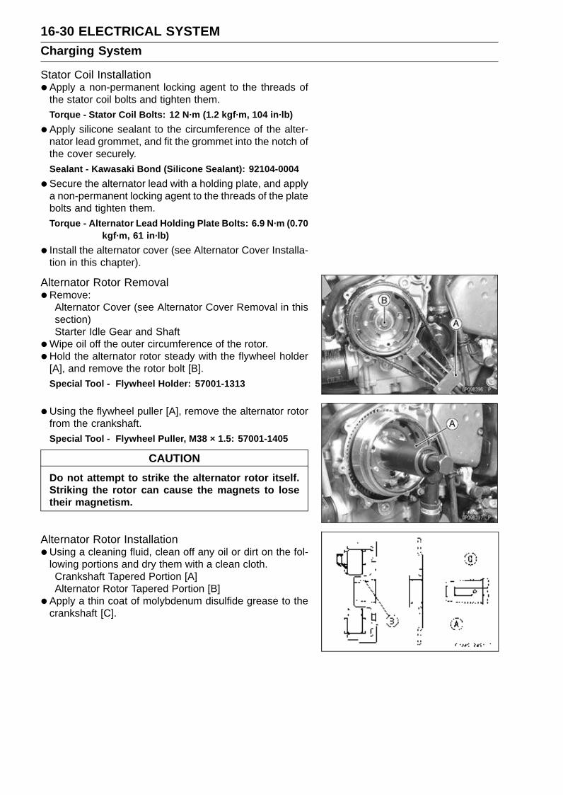
16-30 ELECTRICAL SYSTEMCharging System
Stator Coil Installation•Apply a non-permanent locking agent to the threads of
the stator coil bolts and tighten them.Torque - Stator Coil Bolts: 12 N·m (1.2 kgf·m, 104 in·lb)
•Apply silicone sealant to the circumference of the alter-nator lead grommet, and fit the grommet into the notch ofthe cover securely.Sealant - Kawasaki Bond (Silicone Sealant): 92104-0004
•Secure the alternator lead with a holding plate, and applya non-permanent locking agent to the threads of the platebolts and tighten them.Torque - Alternator Lead Holding Plate Bolts: 6.9 N·m (0.70
kgf·m, 61 in·lb)
• Install the alternator cover (see Alternator Cover Installa-tion in this chapter).
Alternator Rotor Removal•Remove:
Alternator Cover (see Alternator Cover Removal in thissection)Starter Idle Gear and Shaft
•Wipe oil off the outer circumference of the rotor.
• Hold the alternator rotor steady with the flywheel holder[A], and remove the rotor bolt [B].Special Tool - Flywheel Holder: 57001-1313
•Using the flywheel puller [A], remove the alternator rotorfrom the crankshaft.Special Tool - Flywheel Puller, M38 × 1.5: 57001-1405
CAUTION
Do not attempt to strike the alternator rotor itself.Striking the rotor can cause the magnets to losetheir magnetism.
Alternator Rotor Installation•Using a cleaning fluid, clean off any oil or dirt on the fol-
lowing portions and dry them with a clean cloth.Crankshaft Tapered Portion [A]Alternator Rotor Tapered Portion [B]
• Apply a thin coat of molybdenum disulfide grease to thecrankshaft [C].

ELECTRICAL SYSTEM 16-31Charging System
• Install the starter gear [A] and washer [B].
• Again, clean the crankshaft tapered portion [C] and drythere.
• Install the alternator rotor [A] while turning [B] it counter-clockwise.
• Install the washer [A].
NOTEConfirm the alternator rotor fit or not to the crankshaft
before tightening it with specified torque.
• Install the rotor bolt [B] and tighten it with 70 N·m (7.0kgf·m, 52 ft·lb) of torque.
•Remove the rotor bolt.
• Check the tightening torque with flywheel puller [C].If the rotor is not pulled out with 40 N·m (4.1 kgf·m, 30ft·lb) of drawing torque, it is installed correctly.If the rotor is pulled out with under 40 N·m (4.1 kgf·m, 30ft·lb) of drawing torque, clean off any oil dirt or flaw of thecrankshaft and rotor tapered portion, and dry them witha clean cloth. Then, confirm that it is not pulled out withabove torque.
• Tighten the alternator rotor bolt while holding the alterna-tor rotor steadily with the flywheel holder.Special Tool - Flywheel Holder: 57001-1313
Torque - Alternator Rotor Bolt: 110 N·m (11 kgf·m, 81 ft·lb)
•Apply a thin coat of molybdenum disulfide grease to theshaft [A], and install it and starter idle gear [B].
• Install the alternator cover (see Alternator Cover Installa-tion in this chapter).
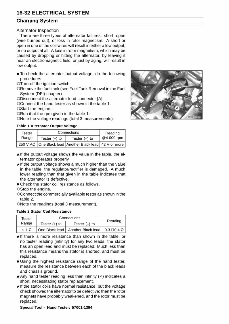
16-32 ELECTRICAL SYSTEMCharging System
Alternator InspectionThere are three types of alternator failures: short, open
(wire burned out), or loss in rotor magnetism. A short oropen in one of the coil wires will result in either a low output,or no output at all. A loss in rotor magnetism, which may becaused by dropping or hitting the alternator, by leaving itnear an electromagnetic field, or just by aging, will result inlow output.
• To check the alternator output voltage, do the followingprocedures.Turn off the ignition switch.Remove the fuel tank (see Fuel Tank Removal in the Fuel
System (DFI) chapter).Disconnect the alternator lead connector [A].Connect the hand tester as shown in the table 1.Start the engine.Run it at the rpm given in the table 1.Note the voltage readings (total 3 measurements).
Table 1 Alternator Output Voltage
ConnectionsTesterRange Tester (+) to Tester (–) to
Reading@4 000 rpm
250 V AC One Black lead Another Black lead 42 V or more
If the output voltage shows the value in the table, the al-ternator operates properly.If the output voltage shows a much higher than the valuein the table, the regulator/rectifier is damaged. A muchlower reading than that given in the table indicates thatthe alternator is defective.
•Check the stator coil resistance as follows.Stop the engine.Connect the commercially available tester as shown in the
table 2.Note the readings (total 3 measurement).
Table 2 Stator Coil Resistance
ConnectionsTesterRange Tester (+) to Tester (–) to
Reading
× 1 Ω One Black lead Another Black lead 0.3 ∼ 0.4 Ω
If there is more resistance than shown in the table, orno tester reading (infinity) for any two leads, the statorhas an open lead and must be replaced. Much less thanthis resistance means the stator is shorted, and must bereplaced.
•Using the highest resistance range of the hand tester,measure the resistance between each of the black leadsand chassis ground.Any hand tester reading less than infinity (∞) indicates ashort, necessitating stator replacement.If the stator coils have normal resistance, but the voltagecheck showed the alternator to be defective; then the rotormagnets have probably weakened, and the rotor must bereplaced.Special Tool - Hand Tester: 57001-1394
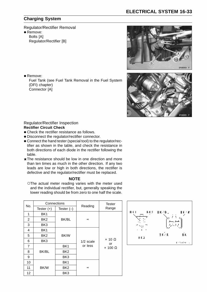
ELECTRICAL SYSTEM 16-33Charging System
Regulator/Rectifier Removal•Remove:
Bolts [A]Regulator/Rectifier [B]
•Remove:Fuel Tank (see Fuel Tank Removal in the Fuel System(DFI) chapter)Connector [A]
Regulator/Rectifier InspectionRectifier Circuit Check
•Check the rectifier resistance as follows.
•Disconnect the regulator/rectifier connector.
• Connect the hand tester (special tool) to the regulator/rec-tifier as shown in the table, and check the resistance inboth directions of each diode in the rectifier following thetable.The resistance should be low in one direction and morethan ten times as much in the other direction. If any twoleads are low or high in both directions, the rectifier isdefective and the regulator/rectifier must be replaced.
NOTEThe actual meter reading varies with the meter used
and the individual rectifier, but, generally speaking thelower reading should be from zero to one half the scale.
ConnectionsNo.
Tester (+) Tester (–)Reading
TesterRange
1 BK1
2 BK2
3 BK3
BK/BL ∞
4 BK1
5 BK2
6 BK3
BK/W
7 BK1
8 BK2
9
BK/BL
BK3
1/2 scaleor less
10 BK1
11 BK2
12
BK/W
BK3
∞
× 10 Ωor
× 100 Ω

16-34 ELECTRICAL SYSTEMCharging System
Regulator Circuit CheckTo test the regulator out of circuit, use three 12 V batteries
and a test light (12 V 3 ∼ 6 W bulb in a socket with leads).
CAUTION
The test light works as an indicator and also a cur-rent limiter to protect the regulator/rectifier from ex-cessive current. Do not use an ammeter instead ofa test light.
•Do the 1st step regulator circuit test.Connect the test light and the 12 V battery to the regula-
tor/rectifier as shown.Check BK1, BK2, and BK3 terminal respectively.
If the test light turns on, the regulator/rectifier is defective.Replace it.If the test light does not turn on, continue the test.
• Do the 2nd step regulator circuit test.Connect the test light and the 12 V battery in the same
manner as specified in the “1st step regulator circuit test”.Apply 12 V to the BK/R terminal.Check BK1, BK2, and BK3 terminal respectively.
If the test light turns on, the regulator/rectifier is defective.Replace it.If the test light does not turn on, continue the test.
• Do the 3rd step regulator circuit test.Connect the test light and the 12 V battery in the same
manner as specified in the “1st step regulator circuit test”.Momentarily apply 24 V to the BK/R terminal by adding a
12 V battery.Check BK1, BK2, and BK3 terminals respectively.
CAUTION
Do not apply more than 24 volts. If more than 24volts is applied the regulator/rectifier may be dam-aged. Do not apply 24 V more than a few seconds.If 24 volts is applied for more than a few seconds,the regulator/rectifier may be damaged.
If the test light did not light when the 24 V was appliedmomentarily to the BK/R terminal, the regulator/rectifieris defective. Replace it.If the regulator/rectifier passes all of the tests described,it may still be defective. If the charging system still doesnot work properly after checking all of the componentsand the battery, test the regulator/rectifier by replacing itwith a known good unit.
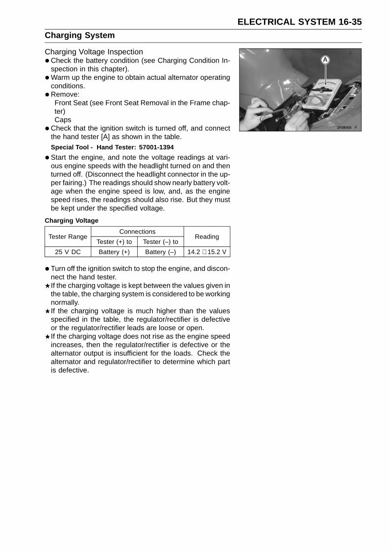
ELECTRICAL SYSTEM 16-35Charging System
Charging Voltage Inspection•Check the battery condition (see Charging Condition In-
spection in this chapter).
•Warm up the engine to obtain actual alternator operatingconditions.
•Remove:Front Seat (see Front Seat Removal in the Frame chap-ter)Caps
•Check that the ignition switch is turned off, and connectthe hand tester [A] as shown in the table.Special Tool - Hand Tester: 57001-1394
•Start the engine, and note the voltage readings at vari-ous engine speeds with the headlight turned on and thenturned off. (Disconnect the headlight connector in the up-per fairing.) The readings should show nearly battery volt-age when the engine speed is low, and, as the enginespeed rises, the readings should also rise. But they mustbe kept under the specified voltage.
Charging Voltage
ConnectionsTester Range
Tester (+) to Tester (–) toReading
25 V DC Battery (+) Battery (–) 14.2 ∼ 15.2 V
• Turn off the ignition switch to stop the engine, and discon-nect the hand tester.If the charging voltage is kept between the values given inthe table, the charging system is considered to be workingnormally.If the charging voltage is much higher than the valuesspecified in the table, the regulator/rectifier is defectiveor the regulator/rectifier leads are loose or open.If the charging voltage does not rise as the engine speedincreases, then the regulator/rectifier is defective or thealternator output is insufficient for the loads. Check thealternator and regulator/rectifier to determine which partis defective.

16-36 ELECTRICAL SYSTEMCharging System
Charging System Circuit
1. Ignition Switch2. Alternator3. Regulator/rectifier4. Main Fuse 30 A5. Battery 12 V 8 Ah6. Load

ELECTRICAL SYSTEM 16-37Starter Motor Clutch
Starter Motor Clutch Removal/Inspection•Refer to the Alternator Rotor Removal and Installation in
this chapter.
Starter Motor Clutch Inspection•Remove:
Alternator Cover (see Alternator Cover Removal in thischapter)Starter Idle Gear
• Turn the starter motor clutch gear [A] by hand. The startermotor clutch gear should turn clockwise [B] freely, butshould not turn counterclockwise [C].If the starter motor clutch does not operate as it should orif it makes noise, go to the next step.
•Disassemble the starter motor clutch, and visually inspectthe clutch parts.If there is any worn or damaged part, replace it.
NOTEExamine the starter motor clutch gear as well. Replace
it if it worn or damaged.
Starter Motor Clutch Disassembly•Remove:
Alternator Rotor (see Alternator Rotor Removal in thischapter)Starter Motor Clutch Bolts [A]Starter Motor Clutch [B]
Starter Motor Clutch Assembly•Apply a non-permanent locking agent to the threads of
the starter motor clutch bolts and tighten them.Torque - Starter Motor Clutch Bolts: 34 N·m (3.5 kgf·m, 25
ft·lb)
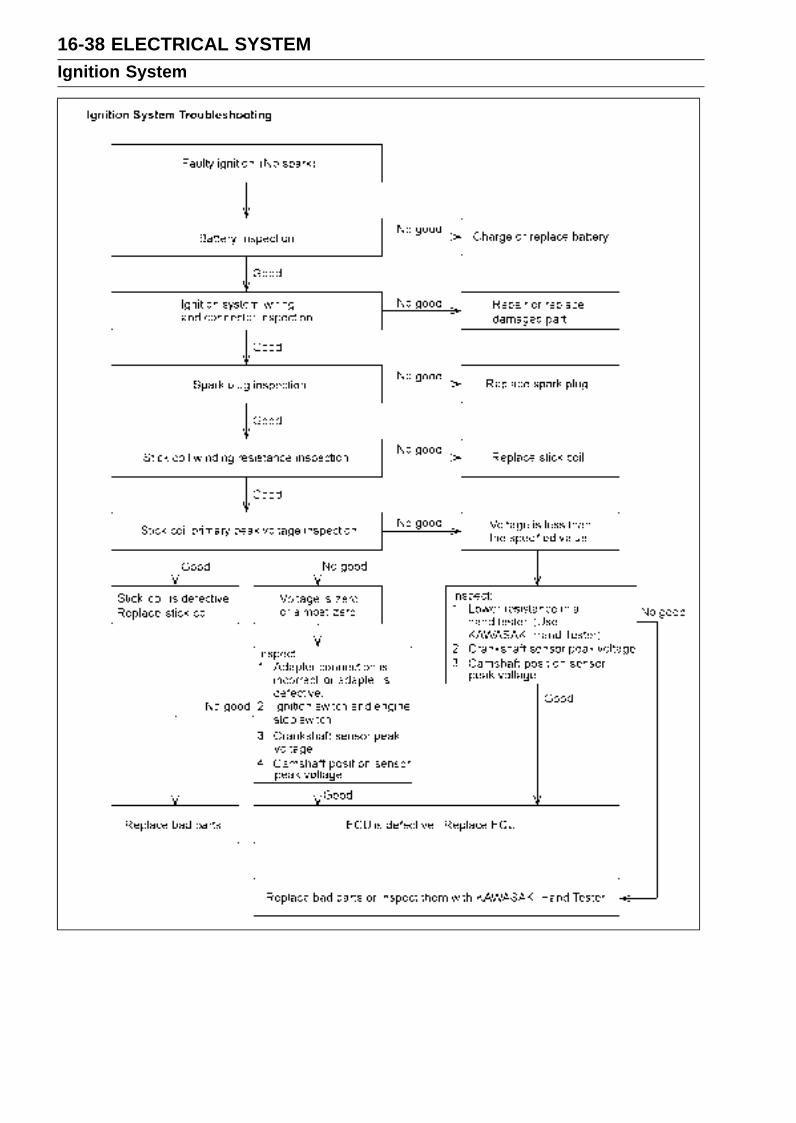
16-38 ELECTRICAL SYSTEMIgnition System
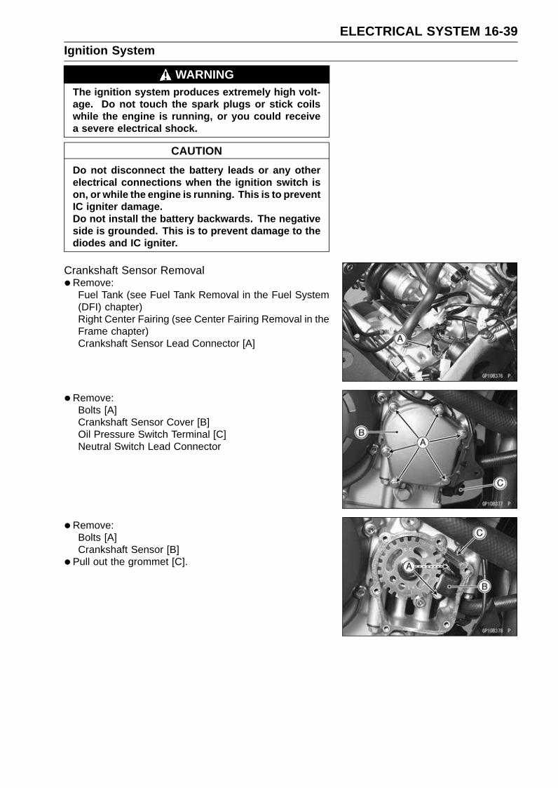
ELECTRICAL SYSTEM 16-39Ignition System
WARNINGThe ignition system produces extremely high volt-age. Do not touch the spark plugs or stick coilswhile the engine is running, or you could receivea severe electrical shock.
CAUTION
Do not disconnect the battery leads or any otherelectrical connections when the ignition switch ison, or while the engine is running. This is to preventIC igniter damage.Do not install the battery backwards. The negativeside is grounded. This is to prevent damage to thediodes and IC igniter.
Crankshaft Sensor Removal•Remove:
Fuel Tank (see Fuel Tank Removal in the Fuel System(DFI) chapter)Right Center Fairing (see Center Fairing Removal in theFrame chapter)Crankshaft Sensor Lead Connector [A]
•Remove:Bolts [A]Crankshaft Sensor Cover [B]Oil Pressure Switch Terminal [C]Neutral Switch Lead Connector
•Remove:Bolts [A]Crankshaft Sensor [B]
• Pull out the grommet [C].
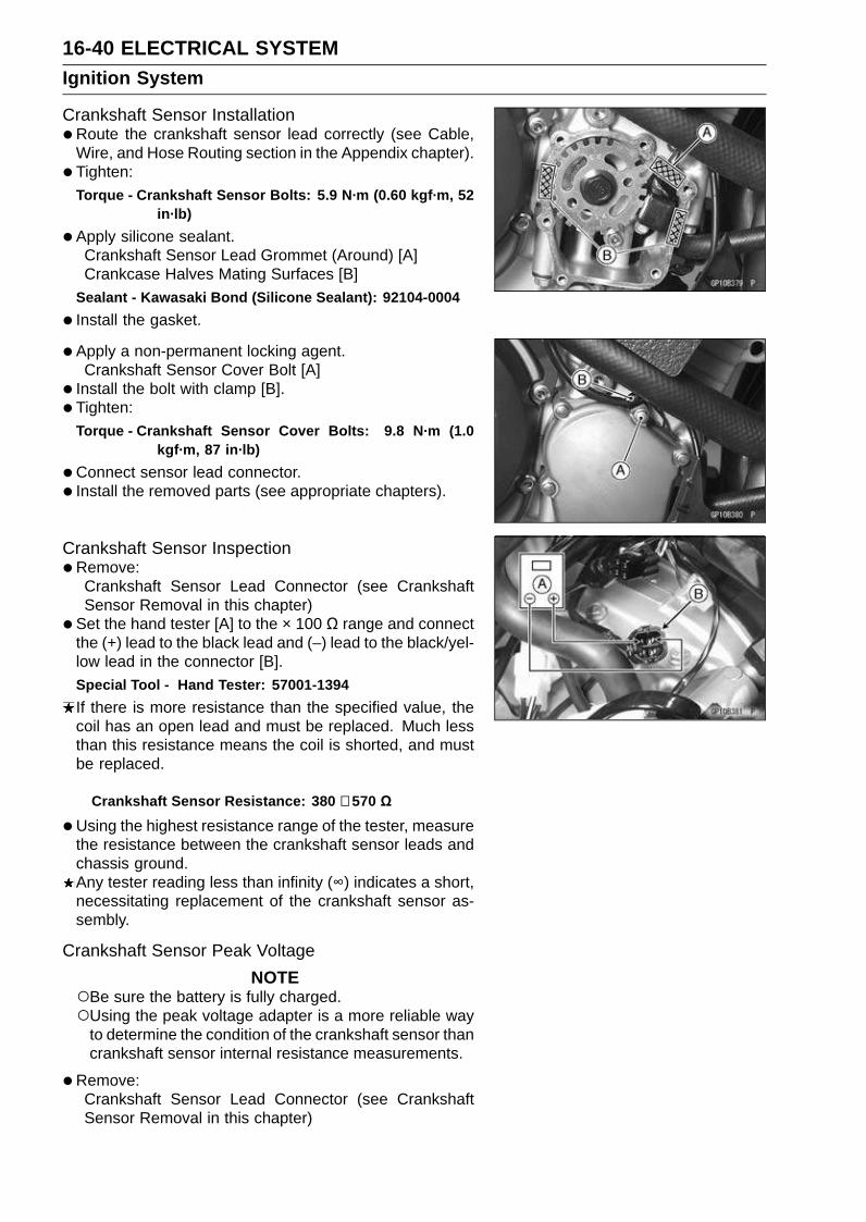
16-40 ELECTRICAL SYSTEMIgnition System
Crankshaft Sensor Installation•Route the crankshaft sensor lead correctly (see Cable,
Wire, and Hose Routing section in the Appendix chapter).
• Tighten:Torque - Crankshaft Sensor Bolts: 5.9 N·m (0.60 kgf·m, 52
in·lb)
•Apply silicone sealant.Crankshaft Sensor Lead Grommet (Around) [A]Crankcase Halves Mating Surfaces [B]
Sealant - Kawasaki Bond (Silicone Sealant): 92104-0004
• Install the gasket.
• Apply a non-permanent locking agent.Crankshaft Sensor Cover Bolt [A]
• Install the bolt with clamp [B].
• Tighten:Torque - Crankshaft Sensor Cover Bolts: 9.8 N·m (1.0
kgf·m, 87 in·lb)
•Connect sensor lead connector.
• Install the removed parts (see appropriate chapters).
Crankshaft Sensor Inspection•Remove:
Crankshaft Sensor Lead Connector (see CrankshaftSensor Removal in this chapter)
• Set the hand tester [A] to the × 100 Ω range and connectthe (+) lead to the black lead and (–) lead to the black/yel-low lead in the connector [B].Special Tool - Hand Tester: 57001-1394
If there is more resistance than the specified value, thecoil has an open lead and must be replaced. Much lessthan this resistance means the coil is shorted, and mustbe replaced.
Crankshaft Sensor Resistance: 380 ∼ 570 Ω
•Using the highest resistance range of the tester, measurethe resistance between the crankshaft sensor leads andchassis ground.Any tester reading less than infinity (∞) indicates a short,necessitating replacement of the crankshaft sensor as-sembly.
Crankshaft Sensor Peak Voltage
NOTEBe sure the battery is fully charged.Using the peak voltage adapter is a more reliable way
to determine the condition of the crankshaft sensor thancrankshaft sensor internal resistance measurements.
•Remove:Crankshaft Sensor Lead Connector (see CrankshaftSensor Removal in this chapter)

ELECTRICAL SYSTEM 16-41Ignition System
•Set the hand tester [A] to the × 10 V DC range, and con-nect it peak voltage adapter [B].
• Connect the black lead (–) [D] of the adapter to black/yel-low lead and red lead (+) [C] to black lead in the crankshaftsensor connector [E].
• Turn the ignition switch on and engine stop switch on.
• Pushing the starter button, turn the engine 4 ∼ 5 sec-onds with the transmission gear in neutral to measure thecrankshaft sensor peak voltage.
•Repeat the measurement 5 or more times.
Crankshaft Sensor Peak VoltageStandard: 3.2 V or more
Special Tools - Hand Tester: 57001-1394Peak Voltage Adapter: 57001-1415Type: KEK-54-9-B
If the tester reading is not specified one, check the crank-shaft sensor.
Timing Rotor Removal•Remove the crankshaft sensor (see Crankshaft Sensor
Removal in this chapter).
• Remove the timing rotor [A].Holding the timing rotor with the flywheel and pulley holder
[B] and unscrew the bolt [C].Special Tool - Flywheel and Pulley Holder: 57001-1605
Timing Rotor Installation•Fit the rotor to the crankshaft.
• Tighten the rotor bolt.
Torque - Timing Rotor Bolt: 45 N·m (4.5 kgf·m, 33 ft·lb)
Special Tool - Flywheel and Pulley Holder: 57001-1605
• Install the crankshaft sensor (see Crankshaft Sensor In-stallation in this chapter).
Stick Coil (Ignition Coil together with Spark Plug Cap)Removal•Remove:
Air Cleaner Housing (see Air Cleaner Housing Removalin the Fuel System (DFI) chapter)
•Disconnect the stick coil connectors [A].
• Pull the stick coils [B] off the spark plugs.
CAUTION
Do not pry the connector part of the coil while re-moving the coil.
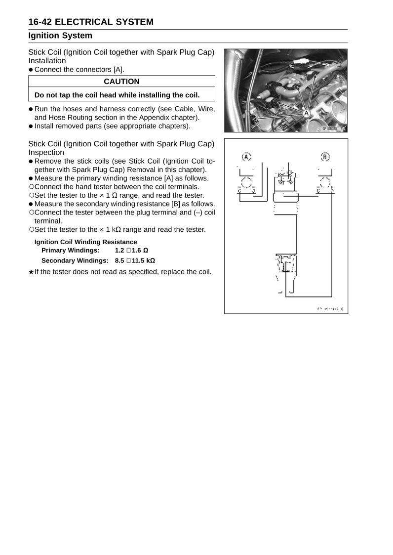
16-42 ELECTRICAL SYSTEMIgnition System
Stick Coil (Ignition Coil together with Spark Plug Cap)Installation•Connect the connectors [A].
CAUTION
Do not tap the coil head while installing the coil.
•Run the hoses and harness correctly (see Cable, Wire,and Hose Routing section in the Appendix chapter).
• Install removed parts (see appropriate chapters).
Stick Coil (Ignition Coil together with Spark Plug Cap)Inspection•Remove the stick coils (see Stick Coil (Ignition Coil to-
gether with Spark Plug Cap) Removal in this chapter).
•Measure the primary winding resistance [A] as follows.Connect the hand tester between the coil terminals.Set the tester to the × 1 Ω range, and read the tester.
•Measure the secondary winding resistance [B] as follows.Connect the tester between the plug terminal and (–) coil
terminal.Set the tester to the × 1 kΩ range and read the tester.
Ignition Coil Winding ResistancePrimary Windings: 1.2 ∼ 1.6 ΩSecondary Windings: 8.5 ∼ 11.5 kΩ
If the tester does not read as specified, replace the coil.
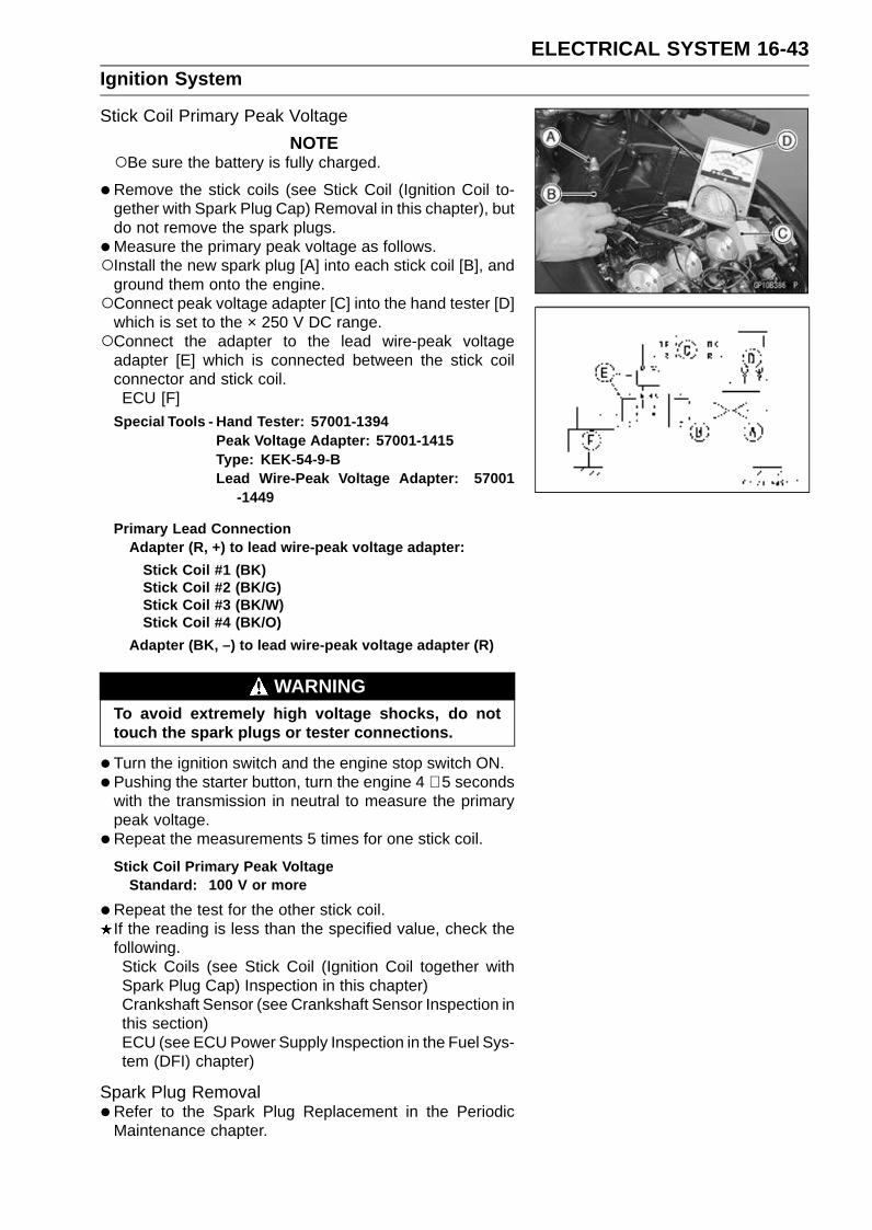
ELECTRICAL SYSTEM 16-43Ignition System
Stick Coil Primary Peak Voltage
NOTEBe sure the battery is fully charged.
•Remove the stick coils (see Stick Coil (Ignition Coil to-gether with Spark Plug Cap) Removal in this chapter), butdo not remove the spark plugs.
•Measure the primary peak voltage as follows.Install the new spark plug [A] into each stick coil [B], and
ground them onto the engine.Connect peak voltage adapter [C] into the hand tester [D]
which is set to the × 250 V DC range.Connect the adapter to the lead wire-peak voltage
adapter [E] which is connected between the stick coilconnector and stick coil.ECU [F]
Special Tools - Hand Tester: 57001-1394Peak Voltage Adapter: 57001-1415Type: KEK-54-9-BLead Wire-Peak Voltage Adapter: 57001
-1449
Primary Lead ConnectionAdapter (R, +) to lead wire-peak voltage adapter:
Stick Coil #1 (BK)Stick Coil #2 (BK/G)Stick Coil #3 (BK/W)Stick Coil #4 (BK/O)
Adapter (BK, –) to lead wire-peak voltage adapter (R)
WARNINGTo avoid extremely high voltage shocks, do nottouch the spark plugs or tester connections.
•Turn the ignition switch and the engine stop switch ON.
•Pushing the starter button, turn the engine 4 ∼ 5 secondswith the transmission in neutral to measure the primarypeak voltage.
•Repeat the measurements 5 times for one stick coil.
Stick Coil Primary Peak VoltageStandard: 100 V or more
•Repeat the test for the other stick coil.If the reading is less than the specified value, check thefollowing.Stick Coils (see Stick Coil (Ignition Coil together withSpark Plug Cap) Inspection in this chapter)Crankshaft Sensor (see Crankshaft Sensor Inspection inthis section)ECU (see ECU Power Supply Inspection in the Fuel Sys-tem (DFI) chapter)
Spark Plug Removal•Refer to the Spark Plug Replacement in the Periodic
Maintenance chapter.

16-44 ELECTRICAL SYSTEMIgnition System
Spark Plug Installation•Refer to the Spark Plug Replacement in the Periodic
Maintenance chapter.
Spark Plug Clean and Inspection•Refer to the Spark Plug Clean and Gap Inspection in the
Periodic Maintenance chapter.
Spark Plug Gap Inspection•Refer to the Spark Plug Clean and Gap Inspection in the
Periodic Maintenance chapter.
Camshaft Position Sensor Removal•Remove:
Right Center Fairing (see Center Fairing Removal in theFrame chapter)Air Cleaner Housing (see Fuel System (DFI) chapter)Connector [A]
•Remove:Camshaft Position Sensor Bolt [A]Camshaft Position Sensor [B]
Camshaft Position Sensor Installation•Apply high-temperature grease to the O-ring on the
camshaft position sensor.
• Tighten:Torque - Camshaft Position Sensor Bolt: 12 N·m (1.2 kgf·m,
104 in·lb)
Camshaft Position Sensor Inspection•Remove:
Camshaft Position Sensor Lead Connector [A] (seeCamshaft Position Sensor Removal in this section)

ELECTRICAL SYSTEM 16-45Ignition System
•Set the hand tester to the × 10 Ω range and connect it tothe terminals.Special Tool - Hand Tester: 57001-1394
If there is more resistance than the specified value, thesensor coil has an open lead and must be replaced. Muchless than this resistance means the sensor coil is shorted,and must be replaced.
Camshaft Position Sensor Resistance: 400 ∼ 460 Ω
•Using the highest resistance range of the tester, mea-sure the resistance between the camshaft position sensorleads and chassis ground.Any tester reading less than infinity (∞) indicates a short,necessitating replacement of the camshaft position sen-sor.
Camshaft Position Sensor Peak Voltage Inspection•Remove:
Camshaft Position Sensor Lead Connector (seeCamshaft Position Sensor Removal in this chapter)
• Set the hand tester [A] to the 10 V DC range.
•Connect commercially available peak voltage adapter [B]to the hand tester and camshaft position sensor leads inthe terminals.Special Tool - Hand Taster: 57001-1394
Peak Voltage Adapter: 57001-1415Type: KEK-54-9-B
Connections:Camshaft PositionSensor Terminal
Adapter Hand Tester
White/Yellow [C] ← Red → (–)
Yellow [D] ← Black → (+)
•Turn the ignition switch and engine stop switch on.
• Pushing the starter button, turn the engine 4 ∼ 5 sec-onds with the transmission gear in neutral to measure thecamshaft position sensor peak voltage.
•Repeat the measurement 5 or more times.
Camshaft Position Sensor Peak VoltageStandard: 0.4 V or more
If the peak voltage is lower than the standard, inspect thecamshaft position sensor.
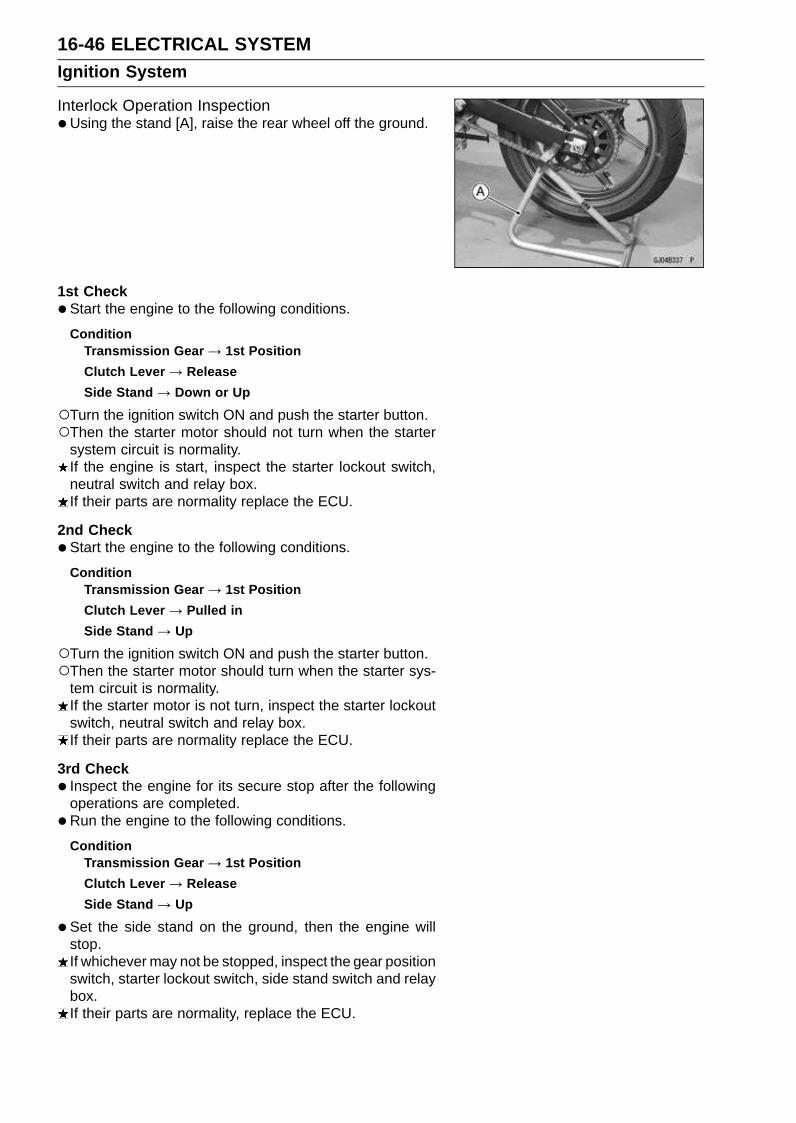
16-46 ELECTRICAL SYSTEMIgnition System
Interlock Operation Inspection•Using the stand [A], raise the rear wheel off the ground.
1st Check
•Start the engine to the following conditions.
ConditionTransmission Gear → 1st Position
Clutch Lever → Release
Side Stand → Down or Up
Turn the ignition switch ON and push the starter button.Then the starter motor should not turn when the starter
system circuit is normality.If the engine is start, inspect the starter lockout switch,neutral switch and relay box.If their parts are normality replace the ECU.
2nd Check
•Start the engine to the following conditions.
ConditionTransmission Gear → 1st Position
Clutch Lever → Pulled in
Side Stand → Up
Turn the ignition switch ON and push the starter button.Then the starter motor should turn when the starter sys-
tem circuit is normality.If the starter motor is not turn, inspect the starter lockoutswitch, neutral switch and relay box.If their parts are normality replace the ECU.
3rd Check
• Inspect the engine for its secure stop after the followingoperations are completed.
•Run the engine to the following conditions.
ConditionTransmission Gear → 1st Position
Clutch Lever → Release
Side Stand → Up
•Set the side stand on the ground, then the engine willstop.If whichever may not be stopped, inspect the gear positionswitch, starter lockout switch, side stand switch and relaybox.If their parts are normality, replace the ECU.
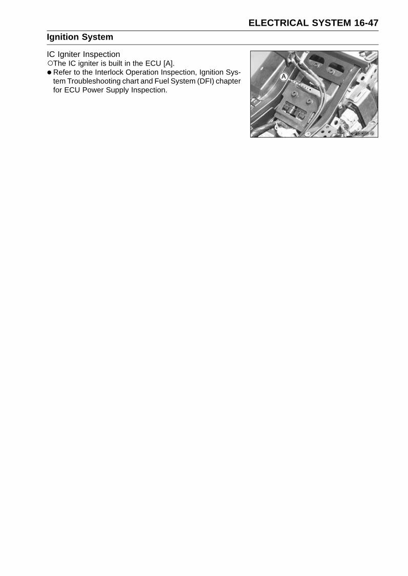
ELECTRICAL SYSTEM 16-47Ignition System
IC Igniter InspectionThe IC igniter is built in the ECU [A].
• Refer to the Interlock Operation Inspection, Ignition Sys-tem Troubleshooting chart and Fuel System (DFI) chapterfor ECU Power Supply Inspection.
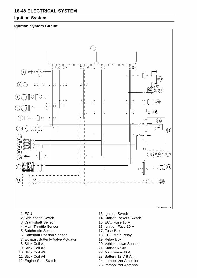
16-48 ELECTRICAL SYSTEMIgnition System
Ignition System Circuit
1. ECU2. Side Stand Switch3. Crankshaft Sensor4. Main Throttle Sensor5. Subthrottle Sensor6. Camshaft Position Sensor7. Exhaust Butterfly Valve Actuator8. Stick Coil #19. Stick Coil #2
10. Stick Coil #311. Stick Coil #412. Engine Stop Switch
13. Ignition Switch14. Starter Lockout Switch15. ECU Fuse 15 A16. Ignition Fuse 10 A17. Fuse Box18. ECU Main Relay19. Relay Box20. Vehicle-down Sensor21. Starter Relay22. Main Fuse 30 A23. Battery 12 V 8 Ah24. Immobilizer Amplifier25. Immobilizer Antenna

ELECTRICAL SYSTEM 16-49Electric Starter System
Starter Motor Removal•Remove the fuel tank (see Fuel Tank Removal in the Fuel
System (DFI) chapter).
• Slide back the rubber cap.
•Remove the starter motor terminal bolt [A] and the mount-ing bolts [B].
• Pull out the starter motor [C].
Starter Motor Installation
CAUTION
Do not tap the starter motor shaft or body. Tappingthe shaft or body could damage the motor.
•When installing the starter motor, clean the starter mo-tor legs [A] and crankcase [B] where the starter motor isgrounded.
•Replace the O-ring [A] with a new one.
• Apply grease to the O-ring.
• Tighten:Torque - Starter Motor Mounting Bolts: 11 N·m (1.1 kgf·m,
97 in·lb)
Starter Motor Disassembly•Take off the starter motor through bolts [A] and remove
both end covers [B] and pull the armature out of the yoke[C].
Starter Motor Assembly•Apply a thin coat of grease to the oil seal [A].
• Fit the toothed washer [B] into the left-hand end cover.
• Install the washer [C].

16-50 ELECTRICAL SYSTEMElectric Starter System
•Press the springs holding the brush leads with suitableclips [A] as shown.
• Put the armature [B] among the brushes.
• Install the O-rings [A] as shown.
• Align the groove [A] in the right-hand end cover and thehollow mark [B] on the yoke.
• Align the hollow mark [A] on the left-hand end cover andthe hollow mark [B] on the yoke.
Brush Inspection•Measure the length [A] of each brush.
If any is worn down to the service limit, replace the brushholder assembly.
Starter Motor Brush LengthStandard: 7 mm (0.28 in.)
Service Limit: 3.5 mm (0.14 in.)

ELECTRICAL SYSTEM 16-51Electric Starter System
Commutator Cleaning and Inspection•Smooth the commutator surface [A] if necessary with fine
emery cloth [B], and clean out the grooves.
•Measure the diameter [A] of the commutator [B].If the commutator diameter is less than the service limit,replace the starter motor with a new one .
Commutator DiameterStandard: 24 mm (0.94 in.)
Service Limit: 23 mm (0.91 in.)
Armature Inspection•Using the × 1 Ω hand tester range, measure the resis-
tance between any two commutator segments [A].Special Tool - Hand Tester: 57001-1394
If there is a high resistance or no reading (∞) between anytwo segments, a winding is open and the starter motormust be replaced.
•Using the highest hand tester range, measure the resis-tance between the segments and the shaft [B].If there is any reading at all, the armature has a short andthe starter motor must be replaced.
NOTEEven if the foregoing checks show the armature to be
good, it may be defective in some manner not readilydetectable with the hand tester. If all other starter motorand starter motor circuit components check good, butthe starter motor still does not turn over or only turnsover weakly, replace the starter motor with a new one.
Brush Lead Inspection•Using the × 1 Ω hand tester range, measure the resis-
tance as shown.Terminal Bolt and Positive Brush [A]Right-hand End Cover and Negative Brush [B]
Special Tool - Hand Tester: 57001-1394
If there is not close to zero ohms, the brush lead has anopen. Replace the positive brush assembly and/or thenegative brush subassembly.

16-52 ELECTRICAL SYSTEMElectric Starter System
Right-hand End Cover Assembly Inspection•Using the highest hand tester range, measure the resis-
tance as shown.Terminal and Right-hand End Cover [A]
Special Tool - Hand Tester: 57001-1394
If there is any reading, the right-hand end cover assemblyhave a short. Replace the right-hand end cover assembly.
Starter Relay Inspection•Remove:
Left Side Cover (see Left Side Cover Removal in theFrame chapter)Connector [A]Battery Cable [B]Starter Cable [C]Starter Relay [D]
•Connect the hand tester [A] and 12 V battery [B] to thestarter relay [C] as shown.Special Tool - Hand Tester: 57001-1394
If the relay does not work as specified, the relay is defec-tive. Replace the relay.
Testing RelayTester Range: × 1 Ω range
Criteria: When battery is connected → 0 ΩWhen battery is disconnected → ∞ Ω

ELECTRICAL SYSTEM 16-53Electric Starter System
Electric Starter Circuit
1. Ignition Switch2. Engine Stop Switch3. Starter Button4. Neutral Switch5. Side Stand Switch6. Battery 12 V 8 Ah7. Starter Relay8. Main Fuse 30 A9. Starter Circuit Relay
10. Ignition Fuse 10 A11. Diode12. Starter Lockout Switch13. Fuse Box14. Relay Box15. Starter Motor
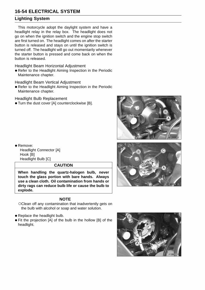
16-54 ELECTRICAL SYSTEMLighting System
This motorcycle adopt the daylight system and have aheadlight relay in the relay box. The headlight does notgo on when the ignition switch and the engine stop switchare first turned on. The headlight comes on after the starterbutton is released and stays on until the ignition switch isturned off. The headlight will go out momentarily wheneverthe starter button is pressed and come back on when thebutton is released.
Headlight Beam Horizontal Adjustment•Refer to the Headlight Aiming Inspection in the Periodic
Maintenance chapter.
Headlight Beam Vertical Adjustment•Refer to the Headlight Aiming Inspection in the Periodic
Maintenance chapter.
Headlight Bulb Replacement•Turn the dust cover [A] counterclockwise [B].
• Remove:Headlight Connector [A]Hook [B]Headlight Bulb [C]
CAUTION
When handling the quartz-halogen bulb, nevertouch the glass portion with bare hands. Alwaysuse a clean cloth. Oil contamination from hands ordirty rags can reduce bulb life or cause the bulb toexplode.
NOTEClean off any contamination that inadvertently gets on
the bulb with alcohol or soap and water solution.
•Replace the headlight bulb.
• Fit the projection [A] of the bulb in the hollow [B] of theheadlight.
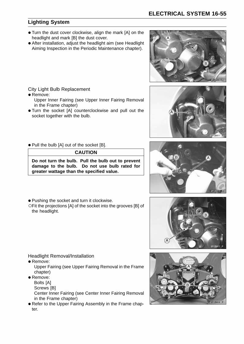
ELECTRICAL SYSTEM 16-55Lighting System
•Turn the dust cover clockwise, align the mark [A] on theheadlight and mark [B] the dust cover.
• After installation, adjust the headlight aim (see HeadlightAiming Inspection in the Periodic Maintenance chapter).
City Light Bulb Replacement•Remove:
Upper Inner Fairing (see Upper Inner Fairing Removalin the Frame chapter)
• Turn the socket [A] counterclockwise and pull out thesocket together with the bulb.
• Pull the bulb [A] out of the socket [B].
CAUTION
Do not turn the bulb. Pull the bulb out to preventdamage to the bulb. Do not use bulb rated forgreater wattage than the specified value.
•Pushing the socket and turn it clockwise.Fit the projections [A] of the socket into the grooves [B] of
the headlight.
Headlight Removal/Installation•Remove:
Upper Fairing (see Upper Fairing Removal in the Framechapter)
•Remove:Bolts [A]Screws [B]Center Inner Fairing (see Center Inner Fairing Removalin the Frame chapter)
•Refer to the Upper Fairing Assembly in the Frame chap-ter.

16-56 ELECTRICAL SYSTEMLighting System
Tail/Brake Light (LED) Removal•Remove:
Seat Cover (see Seat Cover Removal in the Framechapter)
•Unscrew the mounting bolt [A].
• Remove the tail/brake light (LED) [B].
Tail/Brake Light (LED) Installation•Refer to the Seat Cover Installation in the Frame chapter.
License Plate Light Bulb Replacement•Remove:
Screws [A]License Plate Light Cover [B]Bulb
• Insert the new bulb [A] by aligning its upper and lower pins[B] with the upper and lower grooves [C] in the socket, andturn the bulb clockwise.Turn the bulb about 15° degrees.
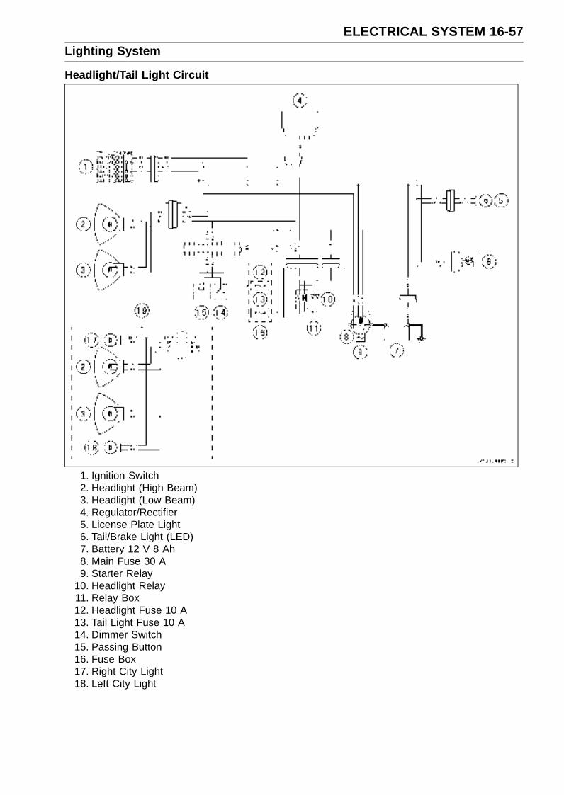
ELECTRICAL SYSTEM 16-57Lighting System
Headlight/Tail Light Circuit
1. Ignition Switch2. Headlight (High Beam)3. Headlight (Low Beam)4. Regulator/Rectifier5. License Plate Light6. Tail/Brake Light (LED)7. Battery 12 V 8 Ah8. Main Fuse 30 A9. Starter Relay
10. Headlight Relay11. Relay Box12. Headlight Fuse 10 A13. Tail Light Fuse 10 A14. Dimmer Switch15. Passing Button16. Fuse Box17. Right City Light18. Left City Light
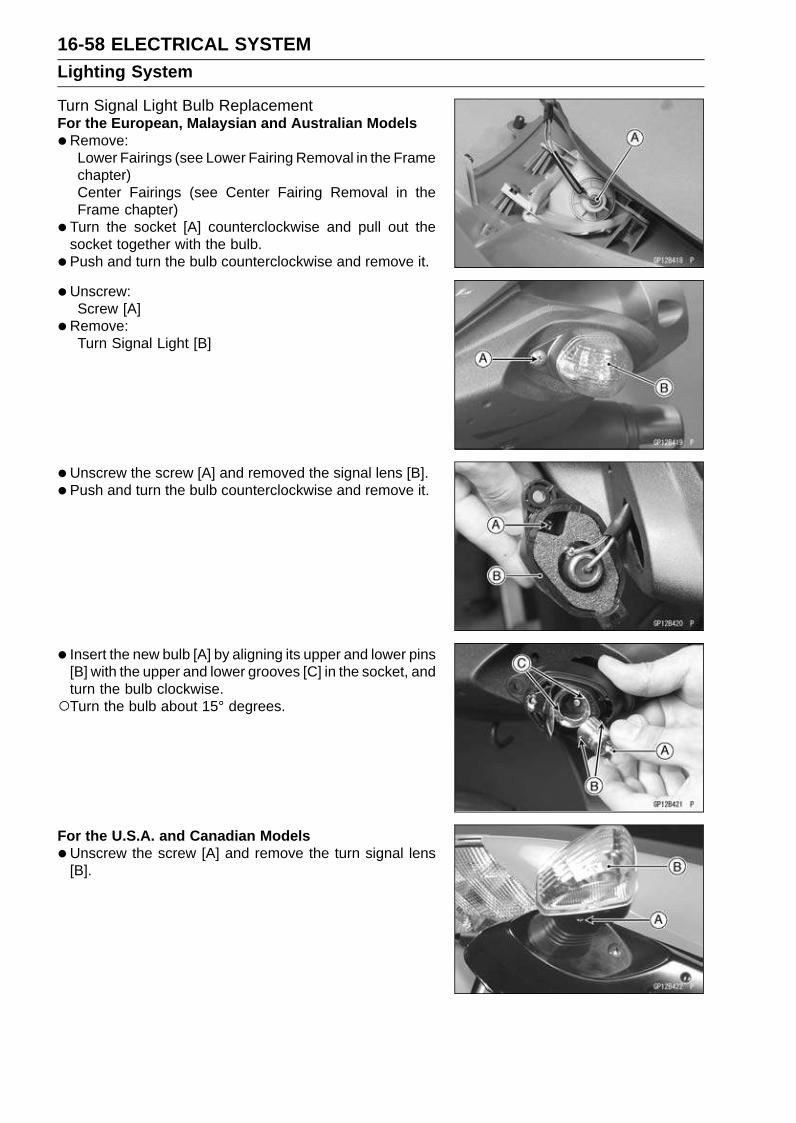
16-58 ELECTRICAL SYSTEMLighting System
Turn Signal Light Bulb ReplacementFor the European, Malaysian and Australian Models
•Remove:Lower Fairings (see Lower Fairing Removal in the Framechapter)Center Fairings (see Center Fairing Removal in theFrame chapter)
• Turn the socket [A] counterclockwise and pull out thesocket together with the bulb.
• Push and turn the bulb counterclockwise and remove it.
• Unscrew:Screw [A]
•Remove:Turn Signal Light [B]
•Unscrew the screw [A] and removed the signal lens [B].
• Push and turn the bulb counterclockwise and remove it.
• Insert the new bulb [A] by aligning its upper and lower pins[B] with the upper and lower grooves [C] in the socket, andturn the bulb clockwise.Turn the bulb about 15° degrees.
For the U.S.A. and Canadian Models
•Unscrew the screw [A] and remove the turn signal lens[B].
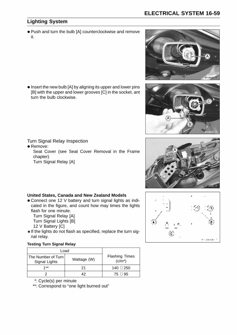
ELECTRICAL SYSTEM 16-59Lighting System
•Push and turn the bulb [A] counterclockwise and removeit.
• Insert the new bulb [A] by aligning its upper and lower pins[B] with the upper and lower grooves [C] in the socket, antturn the bulb clockwise.
Turn Signal Relay Inspection•Remove:
Seat Cover (see Seat Cover Removal in the Framechapter)Turn Signal Relay [A]
United States, Canada and New Zealand Models
•Connect one 12 V battery and turn signal lights as indi-cated in the figure, and count how may times the lightsflash for one minute.Turn Signal Relay [A]Turn Signal Lights [B]12 V Battery [C]
If the lights do not flash as specified, replace the turn sig-nal relay.
Testing Turn Signal Relay
Load
The Number of TurnSignal Lights
Wattage (W)Flashing Times
(c/m*)
1** 21 140 ∼ 250
2 42 75 ∼ 95
*: Cycle(s) per minute**: Correspond to “one light burned out”

16-60 ELECTRICAL SYSTEMLighting System
Other than United States, Canada and New ZealandModels
•Connect one 12 V battery and turn signal lights as indi-cated in the figure, and count how may times the lightsflash for one minute.Turn Signal Relay [A]Turn Signal Lights [B]12 V Battery [C]
If the lights do not flash as specified, replace the turn sig-nal relay.
Testing Turn Signal Relay
Load
The Number of TurnSignal Lights
Wattage (W)Flashing Times
(c/m*)
1** 21 Light stays on
2 42 75 ∼ 95
*: Cycle(s) per minute**: Correspond to “one light burned out”
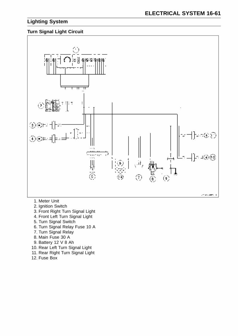
ELECTRICAL SYSTEM 16-61Lighting System
Turn Signal Light Circuit
1. Meter Unit2. Ignition Switch3. Front Right Turn Signal Light4. Front Left Turn Signal Light5. Turn Signal Switch6. Turn Signal Relay Fuse 10 A7. Turn Signal Relay8. Main Fuse 30 A9. Battery 12 V 8 Ah
10. Rear Left Turn Signal Light11. Rear Right Turn Signal Light12. Fuse Box

16-62 ELECTRICAL SYSTEMRadiator Fan System
Fan Motor Inspection•Remove the air cleaner housing (see Air Cleaner Housing
Removal in the Fuel System (DFI) chapter).
• Disconnect the connector [A].
• Using an auxiliary leads, supply battery power to the fanmotor.If the fan does not rotate, the fan motor is defective andmust be replaced.
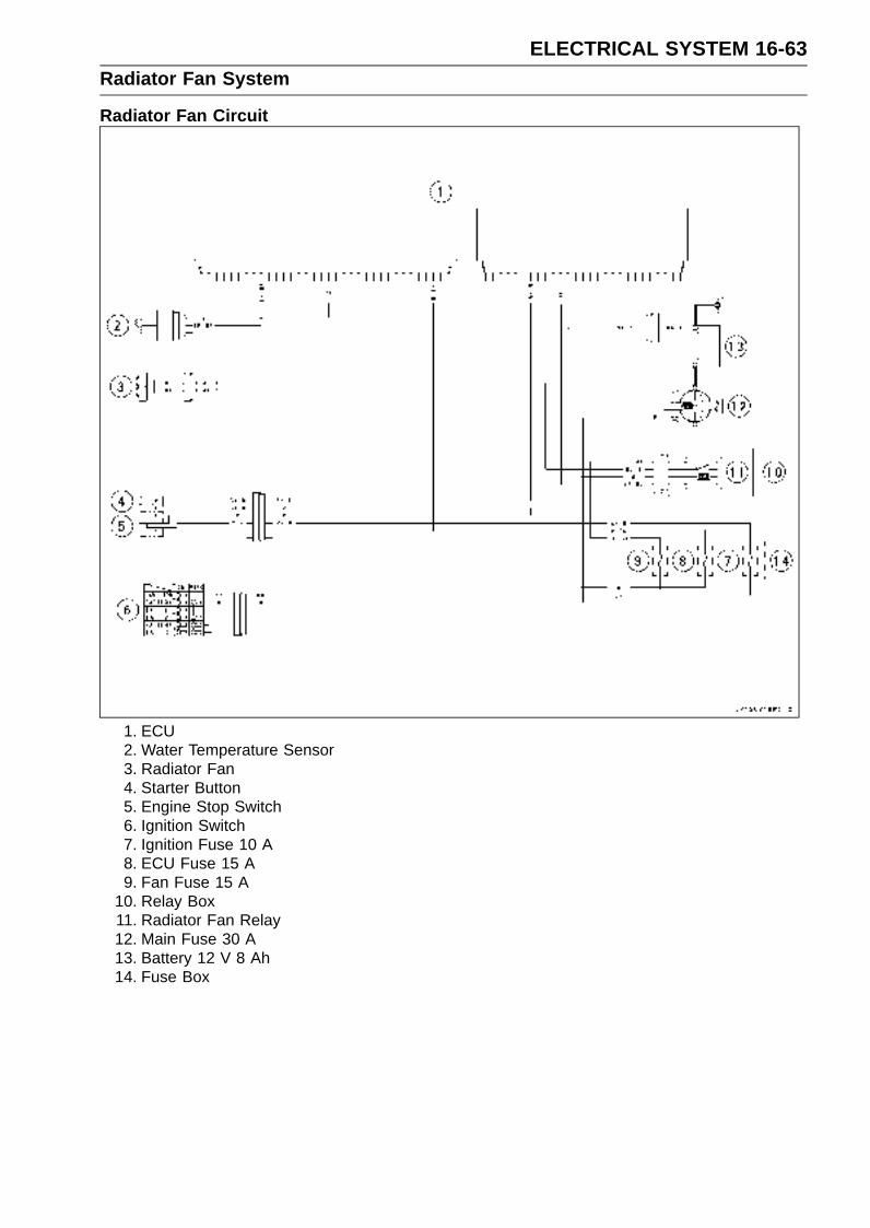
ELECTRICAL SYSTEM 16-63Radiator Fan System
Radiator Fan Circuit
1. ECU2. Water Temperature Sensor3. Radiator Fan4. Starter Button5. Engine Stop Switch6. Ignition Switch7. Ignition Fuse 10 A8. ECU Fuse 15 A9. Fan Fuse 15 A
10. Relay Box11. Radiator Fan Relay12. Main Fuse 30 A13. Battery 12 V 8 Ah14. Fuse Box
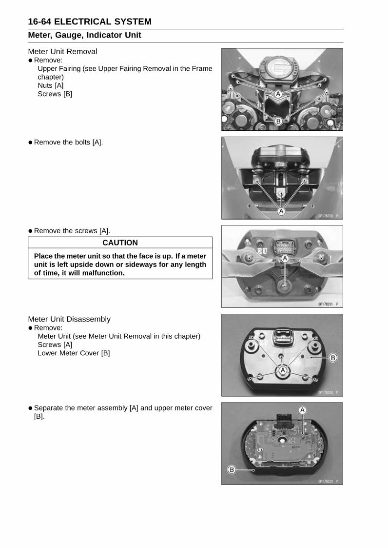
16-64 ELECTRICAL SYSTEMMeter, Gauge, Indicator Unit
Meter Unit Removal•Remove:
Upper Fairing (see Upper Fairing Removal in the Framechapter)Nuts [A]Screws [B]
•Remove the bolts [A].
• Remove the screws [A].
CAUTION
Place the meter unit so that the face is up. If a meterunit is left upside down or sideways for any lengthof time, it will malfunction.
Meter Unit Disassembly•Remove:
Meter Unit (see Meter Unit Removal in this chapter)Screws [A]Lower Meter Cover [B]
• Separate the meter assembly [A] and upper meter cover[B].

ELECTRICAL SYSTEM 16-65Meter, Gauge, Indicator Unit
Electronic Combination Meter Assembly Inspection•Remove the meter assembly [A].
[1] Ignition[2] Fuel Reserve Switch[3] Stop Watch (+)[4] Lap Time (+)[5] Neutral Indicator Light (LED) Ground (–)[6] FI Indicator Light (LED) Ground (–)[7] Tachometer Pulse[8] Water Temperature Sensor[9] Ground (–)
[10] Battery (+)[11] Oil Pressure Warning Indicator Light (LED) Ground
(–)[12] Speed Sensor Supply Voltage[13] Right Turn Signal Light (LED) (+)[14] Left Turn Signal Indicator Light (LED) (+)[15] High Beam Indicator Light (LED)[16] Speed Sensor Pulse
CAUTION
Do not drop the meter unit. Place the meter unit sothat it faces upward. If the meter assembly is left up-side down or sideways for a long time or dropped,it will malfunction.
CAUTION
Do not short each terminals.
Liquid Crystal Display (LCD) Segments Check
•Connect the harness adapter to the meter assembly con-nector.Special Tool - Harness Adapter: 57001-1542
•Using the auxiliary wires, connect the 12 V battery to theeach connector of harness adapter as follows.Connect the battery positive terminal to the terminal [10].Connect the battery negative terminal to the terminal [9].
• Connect the terminal [1] to the terminal [10].

16-66 ELECTRICAL SYSTEMMeter, Gauge, Indicator Unit
The tachometer LCD segments momentarily to it lastreadings two times and segment movement is reversal.When the terminals are connected, all the LCD segments
[A] and LED light [B] appear for three seconds.If the LCD segments and LED warning light will not ap-pear, replace the meter assembly.
•Disconnect the terminal [1].All the LCD segments and LED warning light disappear.
If the segments do not disappear, replace the meter as-sembly.
MODE AND RESET BUTTON Operation Check
•Connect the 12 V battery and terminals in the same man-ner as specified in the “Liquid Crystal Display (LCD) Seg-ments Check”.
• Check that the display [B] change to the ODO, TRIP,CLOCK and STOP WATCH displays each time the modeselector button [A] is pressed.If the fuel level warning indicator light (LED) blinked, dis-
play change to ODO, TRIP, CLOCK, STOP WATCH andFUEL.If the display function does not work, replace the meterassembly.
• Indicate the clock mode.
•Check that when the RESET button in CLOCK mode ispushed for more than two seconds, the meter displayturns to the clock set mode.Both the hour and minute display start flashing.
• In the HOUR/MINUTE setting mode, press the reset but-ton [C] again to effect the HOUR setting mode.The hour display flashes on the display.
• Press the mode selector button [A] to set the hour.
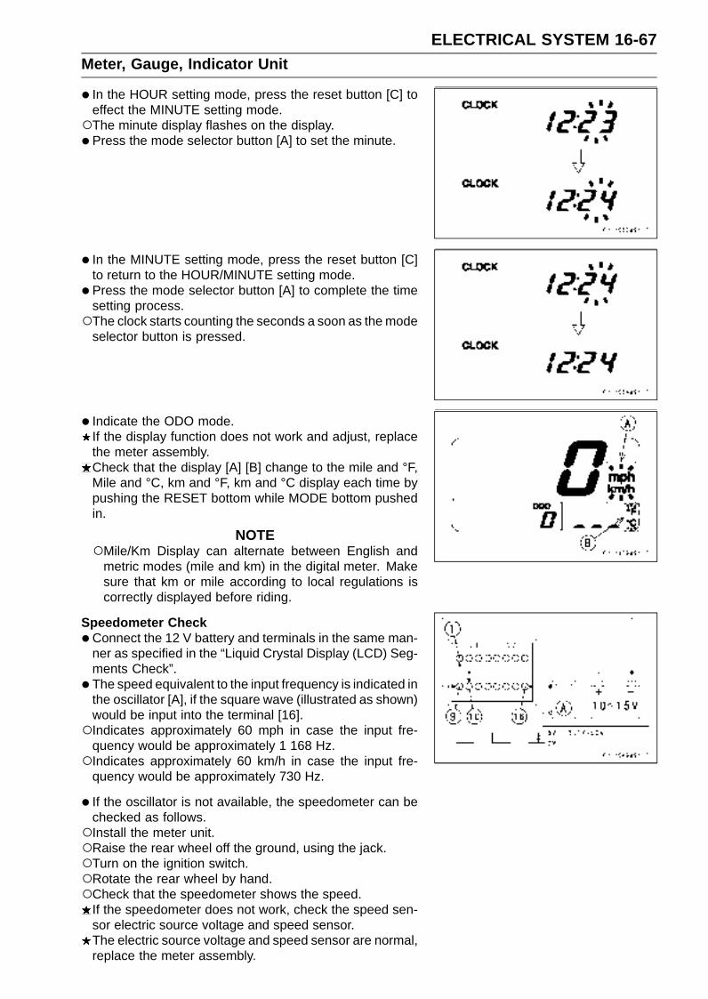
ELECTRICAL SYSTEM 16-67Meter, Gauge, Indicator Unit
• In the HOUR setting mode, press the reset button [C] toeffect the MINUTE setting mode.The minute display flashes on the display.
• Press the mode selector button [A] to set the minute.
• In the MINUTE setting mode, press the reset button [C]to return to the HOUR/MINUTE setting mode.
• Press the mode selector button [A] to complete the timesetting process.The clock starts counting the seconds a soon as the mode
selector button is pressed.
• Indicate the ODO mode.If the display function does not work and adjust, replacethe meter assembly.Check that the display [A] [B] change to the mile and °F,Mile and °C, km and °F, km and °C display each time bypushing the RESET bottom while MODE bottom pushedin.
NOTEMile/Km Display can alternate between English and
metric modes (mile and km) in the digital meter. Makesure that km or mile according to local regulations iscorrectly displayed before riding.
Speedometer Check
•Connect the 12 V battery and terminals in the same man-ner as specified in the “Liquid Crystal Display (LCD) Seg-ments Check”.
• The speed equivalent to the input frequency is indicated inthe oscillator [A], if the square wave (illustrated as shown)would be input into the terminal [16].Indicates approximately 60 mph in case the input fre-
quency would be approximately 1 168 Hz.Indicates approximately 60 km/h in case the input fre-
quency would be approximately 730 Hz.
• If the oscillator is not available, the speedometer can bechecked as follows.Install the meter unit.Raise the rear wheel off the ground, using the jack.Turn on the ignition switch.Rotate the rear wheel by hand.Check that the speedometer shows the speed.
If the speedometer does not work, check the speed sen-sor electric source voltage and speed sensor.The electric source voltage and speed sensor are normal,replace the meter assembly.

16-68 ELECTRICAL SYSTEMMeter, Gauge, Indicator Unit
Speed Sensor Electric Source Check
•Connect the 12 V battery and terminals in the same man-ner as specified in the “Liquid Crystal Display (LCD) Seg-ments Check”.
• Set the hand tester to the DC 25 V range and connect itto the terminals [12] and [9].If the voltage is less than 8 V, replace the meter assembly.
Odometer Check
•Check the odometer with the speedometer check in thesame way.If value indicated in the odometer is not added, replacethe meter assembly.
NOTEThe data is maintained even if the battery is discon-
nected.When the figures come to 999999, they are stopped and
locked.
Trip Meter Check
•Check the trip meter with the speedometer in the sameway.If value indicated in the trip meter is not added, replacethe meter assembly.
•Check that when the RESET button is pushed for morethan two seconds, the figure display turns to 0.0.If the figure display does not indicate 0.0, replace the me-ter assembly.
Water Temperature Meter Check
•Connect the 12 V battery and terminals in the same man-ner as specified in the “Liquid Crystal Display (LCD) Seg-ments Check”.
• Connect the variable rheostat [A] to the terminal [8] asshown.
•Check that the number of segments matches the resis-tance value of the variable rheostat.
Resistance Value (Ω) Temperature Meter Warning Indicate
– [A]–
209.8 50°C (122°F) [B]–
69.1 80°C (176°F) [B]–
21.2 120°C (248°F) [C] Flash
17 HI [D] Flash
• If any display function does not work, replace the meterassembly.
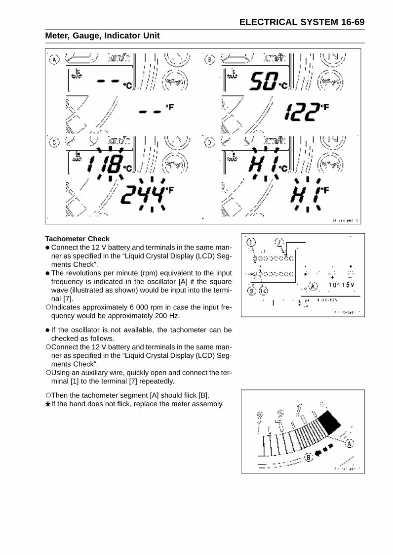
ELECTRICAL SYSTEM 16-69Meter, Gauge, Indicator Unit
Tachometer Check
•Connect the 12 V battery and terminals in the same man-ner as specified in the “Liquid Crystal Display (LCD) Seg-ments Check”.
• The revolutions per minute (rpm) equivalent to the inputfrequency is indicated in the oscillator [A] if the squarewave (illustrated as shown) would be input into the termi-nal [7].Indicates approximately 6 000 rpm in case the input fre-
quency would be approximately 200 Hz.
• If the oscillator is not available, the tachometer can bechecked as follows.Connect the 12 V battery and terminals in the same man-
ner as specified in the “Liquid Crystal Display (LCD) Seg-ments Check”.Using an auxiliary wire, quickly open and connect the ter-
minal [1] to the terminal [7] repeatedly.
Then the tachometer segment [A] should flick [B].If the hand does not flick, replace the meter assembly.
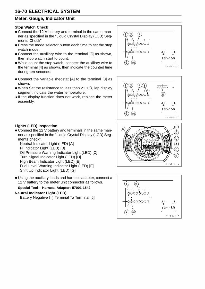
16-70 ELECTRICAL SYSTEMMeter, Gauge, Indicator Unit
Stop Watch Check
•Connect the 12 V battery and terminal in the same man-ner as specified in the “Liquid Crystal Display (LCD) Seg-ments Check”.
• Press the mode selector button each time to set the stopwatch mode.
•Connect the auxiliary wire to the terminal [3] as shown,then stop watch start to count.
•While count the stop watch, connect the auxiliary wire tothe terminal [4] as shown, then indicate the counted timeduring ten seconds.
•Connect the variable rheostat [A] to the terminal [8] asshown.
•When Set the resistance to less than 21.1 Ω, lap displaysegment indicate the water temperature.If the display function does not work, replace the meterassembly.
Lights (LED) Inspection
•Connect the 12 V battery and terminals in the same man-ner as specified in the “Liquid Crystal Display (LCD) Seg-ments check”.Neutral Indicator Light (LED) [A]FI Indicator Light (LED) [B]Oil Pressure Warning Indicator Light (LED) [C]Turn Signal Indicator Light (LED) [D]High Beam Indicator Light (LED) [E]Fuel Level Warning Indicator Light (LED) [F]Shift Up Indicator Light (LED) [G]
•Using the auxiliary leads and harness adapter, connect a12 V battery to the meter unit connector as follows.Special Tool - Harness Adapter: 57001-1542
Neutral Indicator Light (LED)Battery Negative (–) Terminal To Terminal [5]

ELECTRICAL SYSTEM 16-71Meter, Gauge, Indicator Unit
FI Indicator Light (LED)Battery Negative (–) Terminal To Terminal [6]
Oil Pressure Warning Indicator Light (LED)Battery Negative (–) Terminal To Terminal [11]
Right and Left Turn Signal Indicator Light (LED)Battery Positive (+) Terminal to Terminal [13]Battery Positive (+) Terminal to Terminal [14]
High Beam Indicator Light (LED)Battery Positive (+) Terminal to Terminal [15]
Fuel Level Warning Indicator Light (LED)
•Connect a variable rheostat [A] to terminal [2] and [9] asshown.
• Adjust the resistance value to the approximately 22 Ω.The FUEL segments flashes on the display.
If each lights (LED) does not go on, replace the meterassembly.
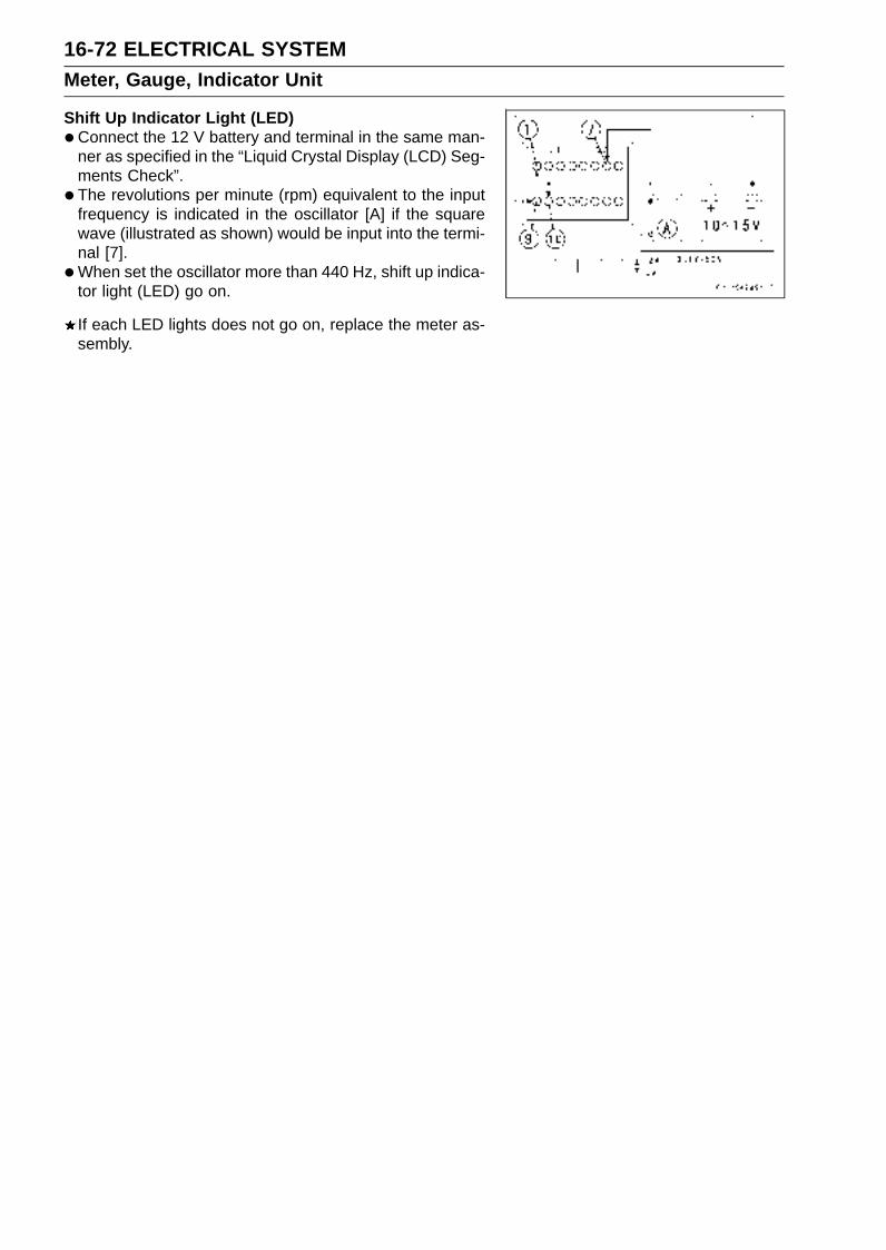
16-72 ELECTRICAL SYSTEMMeter, Gauge, Indicator Unit
Shift Up Indicator Light (LED)
•Connect the 12 V battery and terminal in the same man-ner as specified in the “Liquid Crystal Display (LCD) Seg-ments Check”.
• The revolutions per minute (rpm) equivalent to the inputfrequency is indicated in the oscillator [A] if the squarewave (illustrated as shown) would be input into the termi-nal [7].
•When set the oscillator more than 440 Hz, shift up indica-tor light (LED) go on.
If each LED lights does not go on, replace the meter as-sembly.
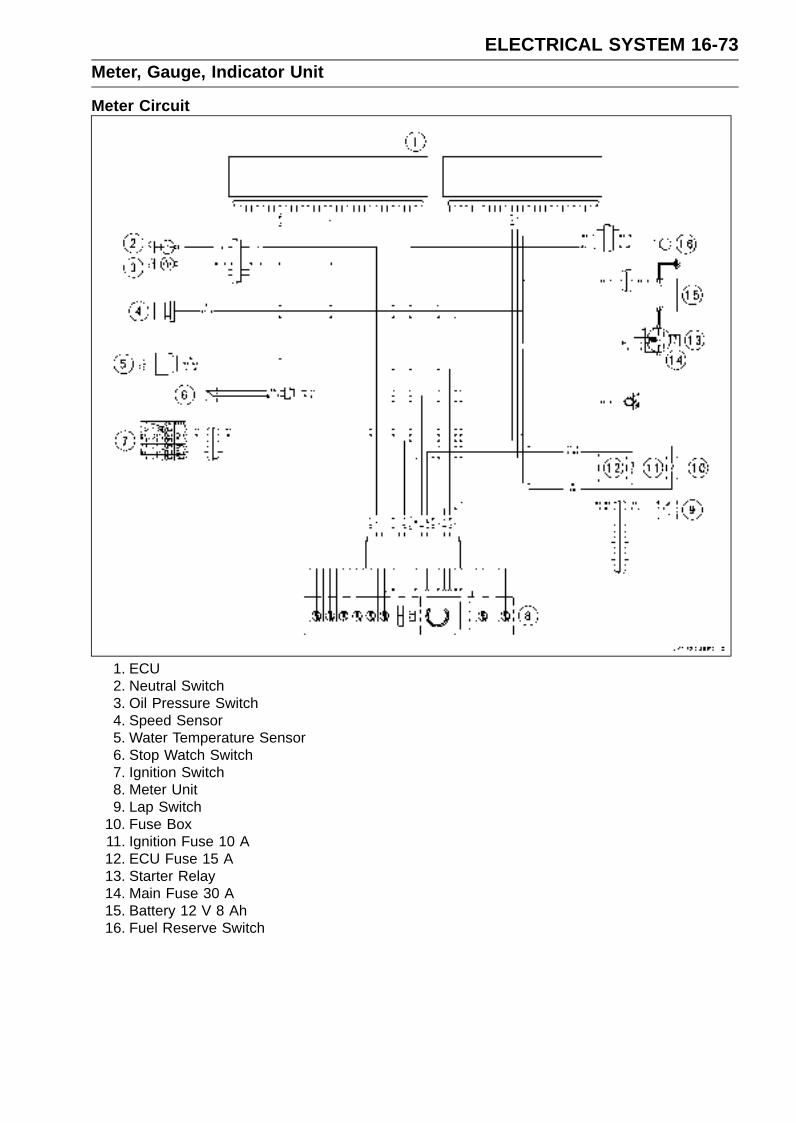
ELECTRICAL SYSTEM 16-73Meter, Gauge, Indicator Unit
Meter Circuit
1. ECU2. Neutral Switch3. Oil Pressure Switch4. Speed Sensor5. Water Temperature Sensor6. Stop Watch Switch7. Ignition Switch8. Meter Unit9. Lap Switch
10. Fuse Box11. Ignition Fuse 10 A12. ECU Fuse 15 A13. Starter Relay14. Main Fuse 30 A15. Battery 12 V 8 Ah16. Fuel Reserve Switch
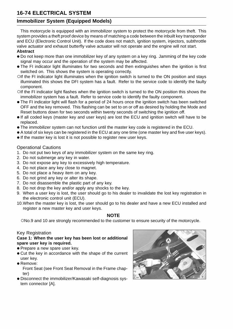
16-74 ELECTRICAL SYSTEMImmobilizer System (Equipped Models)
This motorcycle is equipped with an immobilizer system to protect the motorcycle from theft. Thissystem provides a theft proof device by means of matching a code between the inbuilt key transponderand ECU (Electronic Control Unit). If the code does not match, ignition system, injectors, subthrottlevalve actuator and exhaust butterfly valve actuator will not operate and the engine will not start.Abstract
•Do not keep more than one immobilizer key of any system on a key ring. Jamming of the key codesignal may occur and the operation of the system may be affected.
• The FI indicator light illuminates for two seconds and then extinguishes when the ignition is firstswitched on. This shows the system is operating correctly.If the FI indicator light illuminates when the ignition switch is turned to the ON position and stays
illuminated this shows the DFI system has a fault. Refer to the service code to identify the faultycomponent.If the FI indicator light flashes when the ignition switch is turned to the ON position this shows the
immobilizer system has a fault. Refer to service code to identify the faulty component.
• The FI indicator light will flash for a period of 24 hours once the ignition switch has been switchedOFF and the key removed. This flashing can be set to on or off as desired by holding the Mode andReset buttons down for two seconds within twenty seconds of switching the ignition off.
• If all coded keys (master key and user keys) are lost the ECU and ignition switch will have to bereplaced.
• The immobilizer system can not function until the master key code is registered in the ECU.
•A total of six keys can be registered in the ECU at any one time (one master key and five user keys).
• If the master key is lost it is not possible to register new user keys.
Operational Cautions1. Do not put two keys of any immobilizer system on the same key ring.2. Do not submerge any key in water.3. Do not expose any key to excessively high temperature.4. Do not place any key close to magnet.5. Do not place a heavy item on any key.6. Do not grind any key or alter its shape.7. Do not disassemble the plastic part of any key.8. Do not drop the key and/or apply any shocks to the key.9. When a user key is lost, the user should go to his dealer to invalidate the lost key registration in
the electronic control unit (ECU).10.When the master key is lost, the user should go to his dealer and have a new ECU installed and
register a new master key and user keys.
NOTENo.9 and 10 are strongly recommended to the customer to ensure security of the motorcycle.
Key RegistrationCase 1: When the user key has been lost or additionalspare user key is required.
•Prepare a new spare user key.
•Cut the key in accordance with the shape of the currentuser key.
•Remove:Front Seat (see Front Seat Removal in the Frame chap-ter)
•Disconnect the immobilizer/Kawasaki self-diagnosis sys-tem connector [A].

ELECTRICAL SYSTEM 16-75Immobilizer System (Equipped Models)
•Connect the key registration unit [A].Special Tool - Key Registration Unit: 57001-1582
• Insert the master key to the ignition switch and turn it ON.VerifiedThe FI indicator light [A] blinks to display the registration
mode (go to the next step).
Not VerifiedThe FI indicator light [A] blinks to display the collation error
(refer to the following failure illustrations).Immobilizer Amplifier Failure
Master Key Collation Error
• Turn the master key OFF and remove the master key.The FI indicator light [A] blinks continuously to display that
the ECU is in the registration mode for 15 seconds.
NOTEInsert next key and turn ON within 15 seconds after pre-
vious key is turned off and removed otherwise registra-tion mode will be ended and the FI indicator light stopsflashing.To return to the registration mode start the master key
verification procedure. This applies to all user key reg-istration.
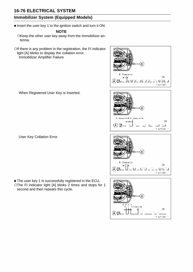
16-76 ELECTRICAL SYSTEMImmobilizer System (Equipped Models)
• Insert the user key 1 to the ignition switch and turn it ON.
NOTEKeep the other user key away from the immobilizer an-
tenna.
If there is any problem in the registration, the FI indicatorlight [A] blinks to display the collation error.Immobilizer Amplifier Failure
When Registered User Key is Inserted.
User Key Collation Error
• The user key 1 is successfully registered in the ECU.The FI indicator light [A] blinks 2 times and stops for 1
second and then repeats this cycle.
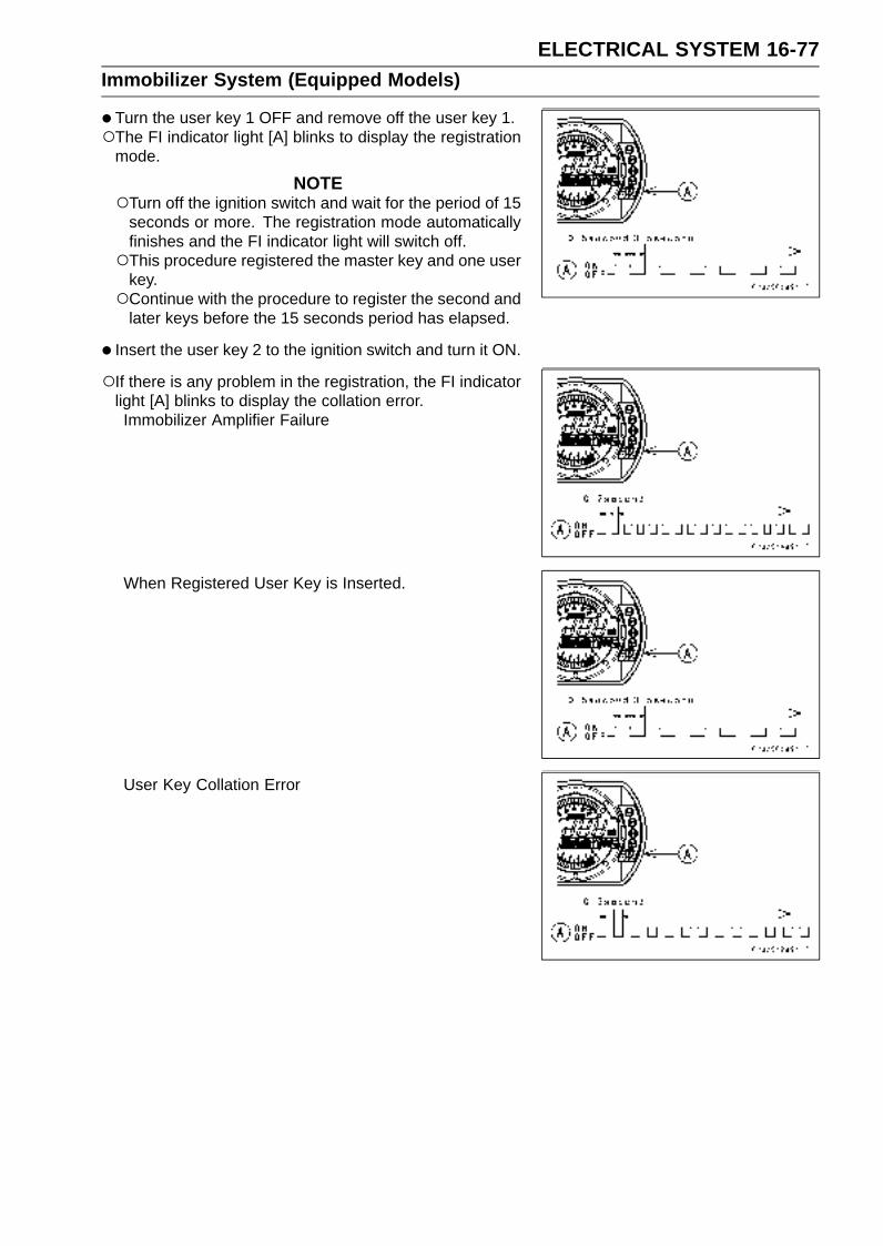
ELECTRICAL SYSTEM 16-77Immobilizer System (Equipped Models)
•Turn the user key 1 OFF and remove off the user key 1.The FI indicator light [A] blinks to display the registration
mode.
NOTETurn off the ignition switch and wait for the period of 15
seconds or more. The registration mode automaticallyfinishes and the FI indicator light will switch off.This procedure registered the master key and one user
key.Continue with the procedure to register the second and
later keys before the 15 seconds period has elapsed.
• Insert the user key 2 to the ignition switch and turn it ON.
If there is any problem in the registration, the FI indicatorlight [A] blinks to display the collation error.Immobilizer Amplifier Failure
When Registered User Key is Inserted.
User Key Collation Error

16-78 ELECTRICAL SYSTEMImmobilizer System (Equipped Models)
•The user key 2 is registered in the ECU.The FI indicator light [A] blinks 3 times and stops for 1
second and then repeats this cycle.This procedure has registered the master key and 2 user
keys.
•Continue with the procedure to register an additional 3user keys.
NOTEThe ECU can store up the six key codes (master key ×
1 and user key × 5).
User Key Indicator Flashes
FI IndicatorLight Blinks
FI IndicatorLight Stop
Remarks
User Key 3 4 times 1 seconds Repeat
User Key 4 5 times 1 seconds Repeat
User Key 5 6 times 1 seconds Repeat
• Turn OFF the ignition switch and wait for period of morethan 15 seconds.
• The registration mode automatically ends.
• FI indicator light goes off [A].
• Remove the key registration unit and connect the immo-bilizer Kawasaki self-diagnostic system connector.
NOTETurn the ignition switch ON with the registered user key.Check that the engine can be started using all regis-
tered user keys.
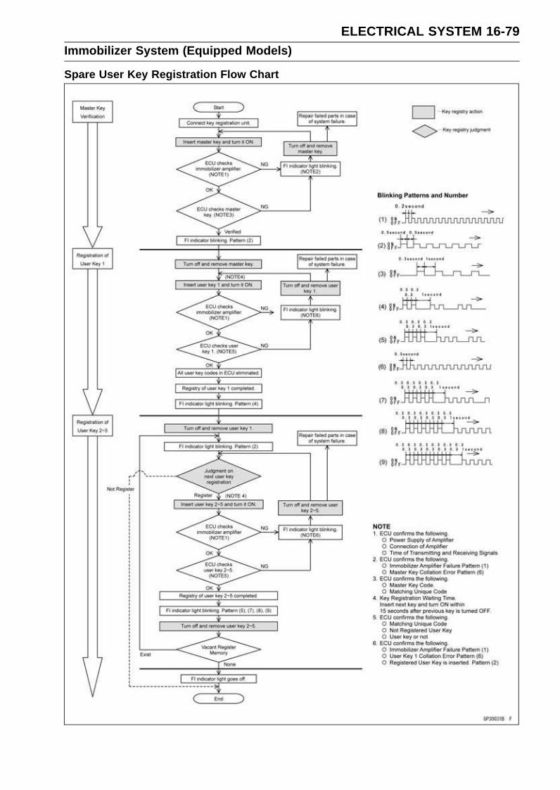
ELECTRICAL SYSTEM 16-79Immobilizer System (Equipped Models)
Spare User Key Registration Flow Chart
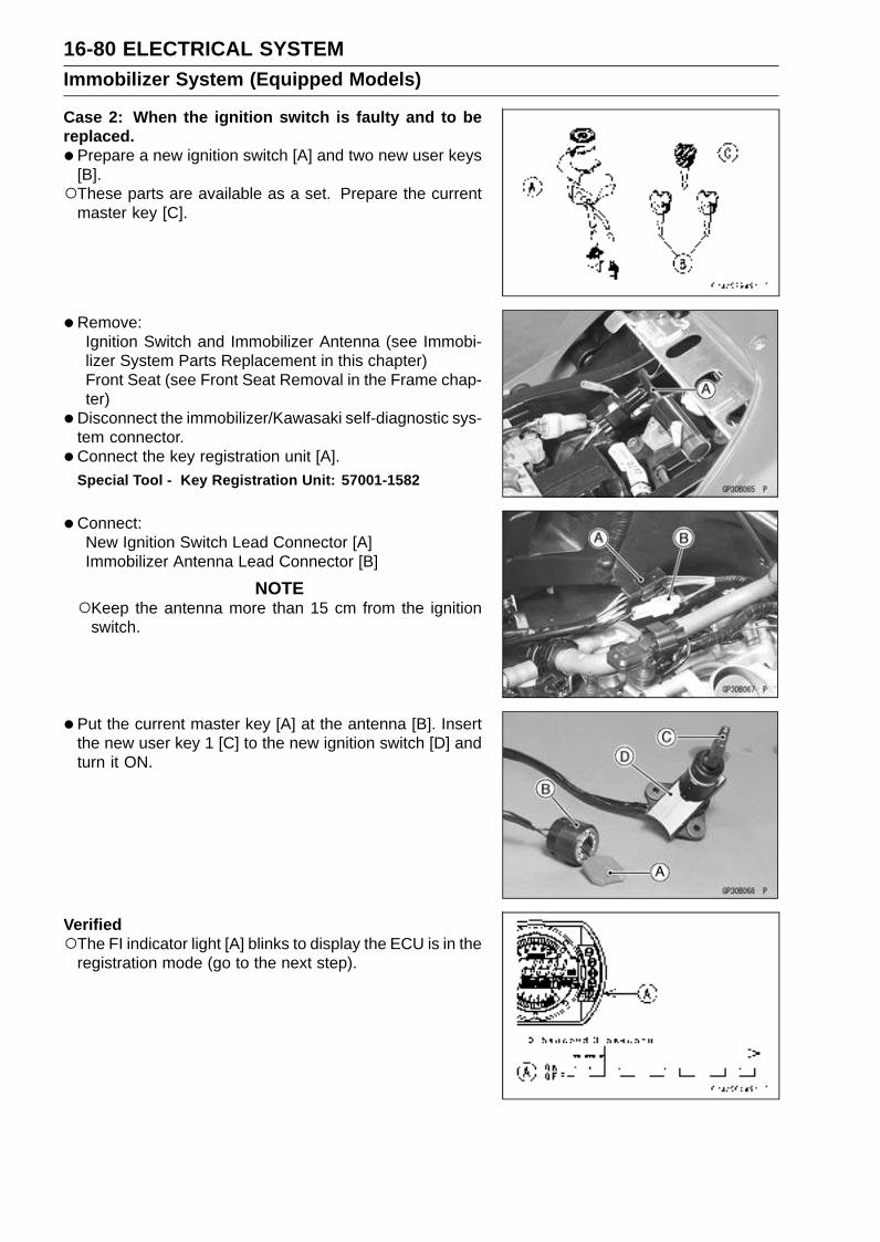
16-80 ELECTRICAL SYSTEMImmobilizer System (Equipped Models)
Case 2: When the ignition switch is faulty and to bereplaced.
•Prepare a new ignition switch [A] and two new user keys[B].These parts are available as a set. Prepare the current
master key [C].
• Remove:Ignition Switch and Immobilizer Antenna (see Immobi-lizer System Parts Replacement in this chapter)Front Seat (see Front Seat Removal in the Frame chap-ter)
•Disconnect the immobilizer/Kawasaki self-diagnostic sys-tem connector.
• Connect the key registration unit [A].Special Tool - Key Registration Unit: 57001-1582
•Connect:New Ignition Switch Lead Connector [A]Immobilizer Antenna Lead Connector [B]
NOTEKeep the antenna more than 15 cm from the ignition
switch.
•Put the current master key [A] at the antenna [B]. Insertthe new user key 1 [C] to the new ignition switch [D] andturn it ON.
VerifiedThe FI indicator light [A] blinks to display the ECU is in the
registration mode (go to the next step).
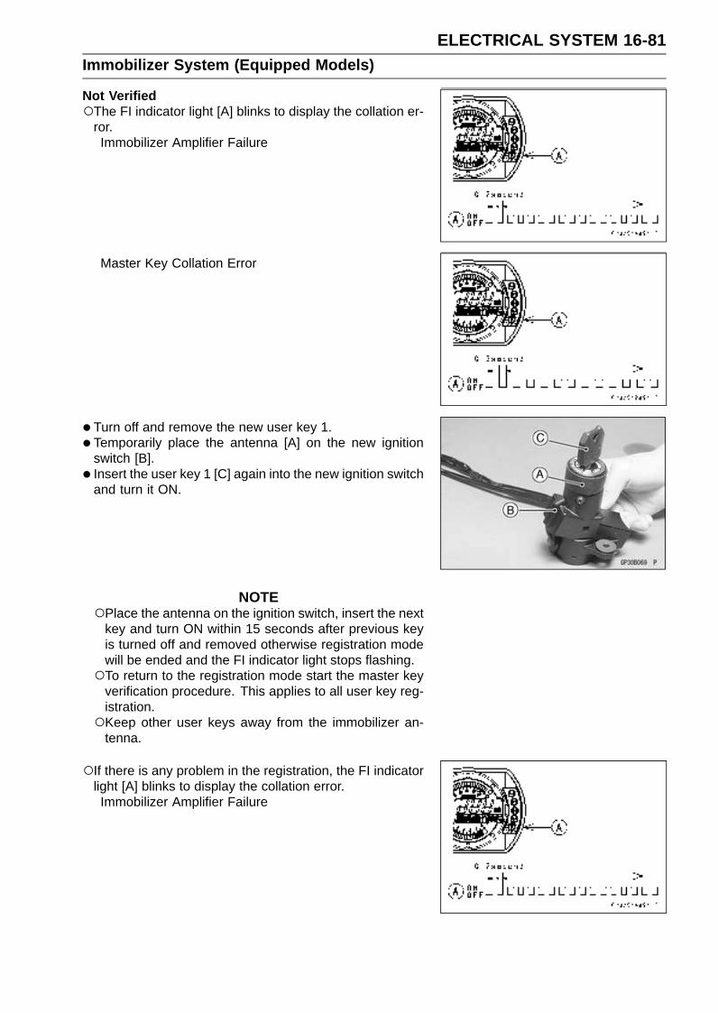
ELECTRICAL SYSTEM 16-81Immobilizer System (Equipped Models)
Not VerifiedThe FI indicator light [A] blinks to display the collation er-
ror.Immobilizer Amplifier Failure
Master Key Collation Error
• Turn off and remove the new user key 1.
• Temporarily place the antenna [A] on the new ignitionswitch [B].
• Insert the user key 1 [C] again into the new ignition switchand turn it ON.
NOTEPlace the antenna on the ignition switch, insert the next
key and turn ON within 15 seconds after previous keyis turned off and removed otherwise registration modewill be ended and the FI indicator light stops flashing.To return to the registration mode start the master key
verification procedure. This applies to all user key reg-istration.Keep other user keys away from the immobilizer an-
tenna.
If there is any problem in the registration, the FI indicatorlight [A] blinks to display the collation error.Immobilizer Amplifier Failure
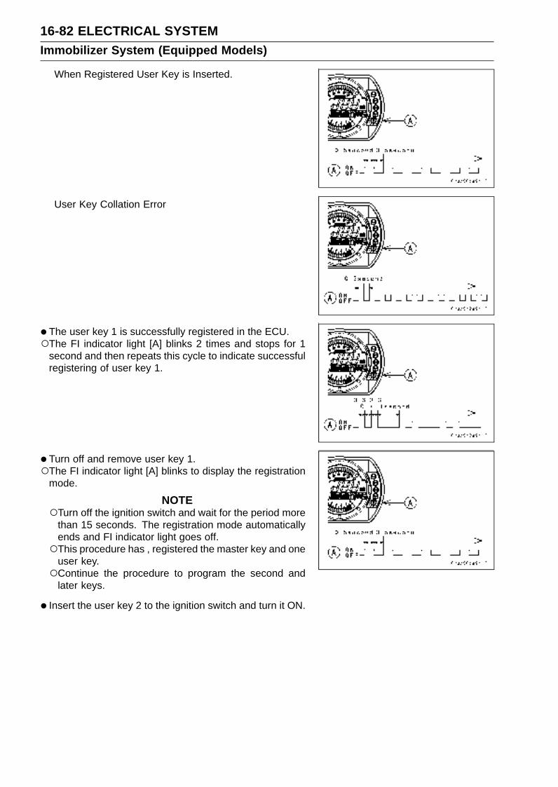
16-82 ELECTRICAL SYSTEMImmobilizer System (Equipped Models)
When Registered User Key is Inserted.
User Key Collation Error
• The user key 1 is successfully registered in the ECU.The FI indicator light [A] blinks 2 times and stops for 1
second and then repeats this cycle to indicate successfulregistering of user key 1.
• Turn off and remove user key 1.The FI indicator light [A] blinks to display the registration
mode.
NOTETurn off the ignition switch and wait for the period more
than 15 seconds. The registration mode automaticallyends and FI indicator light goes off.This procedure has , registered the master key and one
user key.Continue the procedure to program the second and
later keys.
• Insert the user key 2 to the ignition switch and turn it ON.

ELECTRICAL SYSTEM 16-83Immobilizer System (Equipped Models)
If there is any problem in the registration, the FI indicatorlight [A] blinks to display the collation error.Immobilizer Amplifier Failure
When Registered User Key is Inserted.
User Key Collation Error
• The user key 2 is successfully registered in the ECU.The FI indicator light [A] blinks 3 times and stops for 1
second and then repeat this cycle to indicate successfulprogramming of user key 2.
• Turn OFF the ignition switch and wait for period more than15 seconds.
• The registration mode automatically ends.
• FI indicator light goes off [A].

16-84 ELECTRICAL SYSTEMImmobilizer System (Equipped Models)
•Remove the key registration unit and connect the immo-bilizer/Kawasaki self-diagnostic system connector.
NOTETurn the ignition switch ON with the registered user key.Check that the engine can be started using all regis-
tered user keys.
• Install the new ignition switch and antenna.
Case 3: When the electric control unit (ECU) is faultyand has to be replaced.
•Prepare a new ECU [A], current master key [B] and cur-rent user keys [C].
NOTEThe key registration unit is not required.
•Replace:Electric Control Unit [A] (see Immobilizer System PartsReplacement in this chapter)
• Insert the current master key into the ignition switch andturn it ON.
If there is any problem in the registration, the FI indicatorlight [A] blinks to display the collation error.Immobilizer Amplifier Failure
Master Key Collation Error

ELECTRICAL SYSTEM 16-85Immobilizer System (Equipped Models)
•The master key is registered in the ECU.The FI indicator light [A] blinks 1 time and stops for 1
second and the repeats this cycle to indicate successfulregistration of the master key.
• Turn of the master key and remove it.The FI indicator light [A] blinks to display the registration
mode.
NOTEInsert next key and turn ON within 15 seconds after pre-
vious key is turned off and removed otherwise registra-tion mode will be ended and the FI indicator light goesoff.To return to the registration mode start the master key
verification procedure. This applies to all user key reg-istration.
• Insert the user key 1 to the ignition switch and turn it ON.
NOTEKeep the other user keys away from the immobilizer
antenna.
If there is any problem in the registration, the FI indicatorlight [A] blinks to display the collation error.Immobilizer Amplifier Failure
When Registered User Key is Inserted.

16-86 ELECTRICAL SYSTEMImmobilizer System (Equipped Models)
User Key Collation Error
• The user key 1 is registered in the ECU.The FI indicator light [A] blinks 2 times and stops for 1
second and then repeats this cycle to indicate successfulregistration of user key.
• Turn off and remove the user key 1.The FI indicator light [A] blinks to display the registration
mode codes.
NOTEInsert next key and turn ON within 15 seconds after pre-
vious key is turned off and removed otherwise registra-tion mode will be ended and the FI indicator light goesoff.To return to the registration mode start the master key
verification procedure. This applies to all user key reg-istration.
• Insert the user key 2 to the ignition switch and turn it ON.
If there is any problem in the registration, the FI indicatorlight [A] blinks to display the collation error code.Immobilizer Amplifier Failure
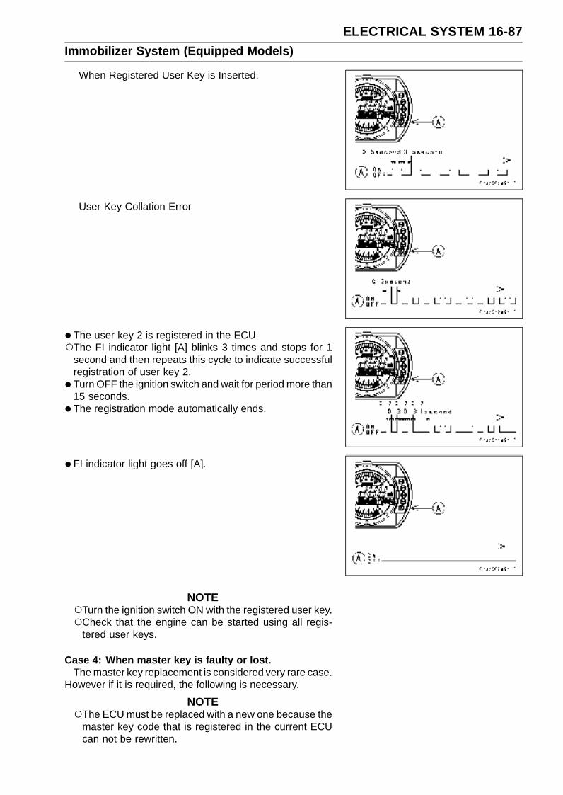
ELECTRICAL SYSTEM 16-87Immobilizer System (Equipped Models)
When Registered User Key is Inserted.
User Key Collation Error
• The user key 2 is registered in the ECU.The FI indicator light [A] blinks 3 times and stops for 1
second and then repeats this cycle to indicate successfulregistration of user key 2.
• Turn OFF the ignition switch and wait for period more than15 seconds.
• The registration mode automatically ends.
• FI indicator light goes off [A].
NOTETurn the ignition switch ON with the registered user key.Check that the engine can be started using all regis-
tered user keys.
Case 4: When master key is faulty or lost.The master key replacement is considered very rare case.
However if it is required, the following is necessary.
NOTEThe ECU must be replaced with a new one because the
master key code that is registered in the current ECUcan not be rewritten.
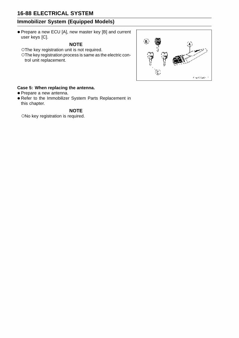
16-88 ELECTRICAL SYSTEMImmobilizer System (Equipped Models)
•Prepare a new ECU [A], new master key [B] and currentuser keys [C].
NOTEThe key registration unit is not required.The key registration process is same as the electric con-
trol unit replacement.
Case 5: When replacing the antenna.
•Prepare a new antenna.
•Refer to the Immobilizer System Parts Replacement inthis chapter.
NOTENo key registration is required.

ELECTRICAL SYSTEM 16-89Immobilizer System (Equipped Models)
All Keys Initial Registration Flow Chart
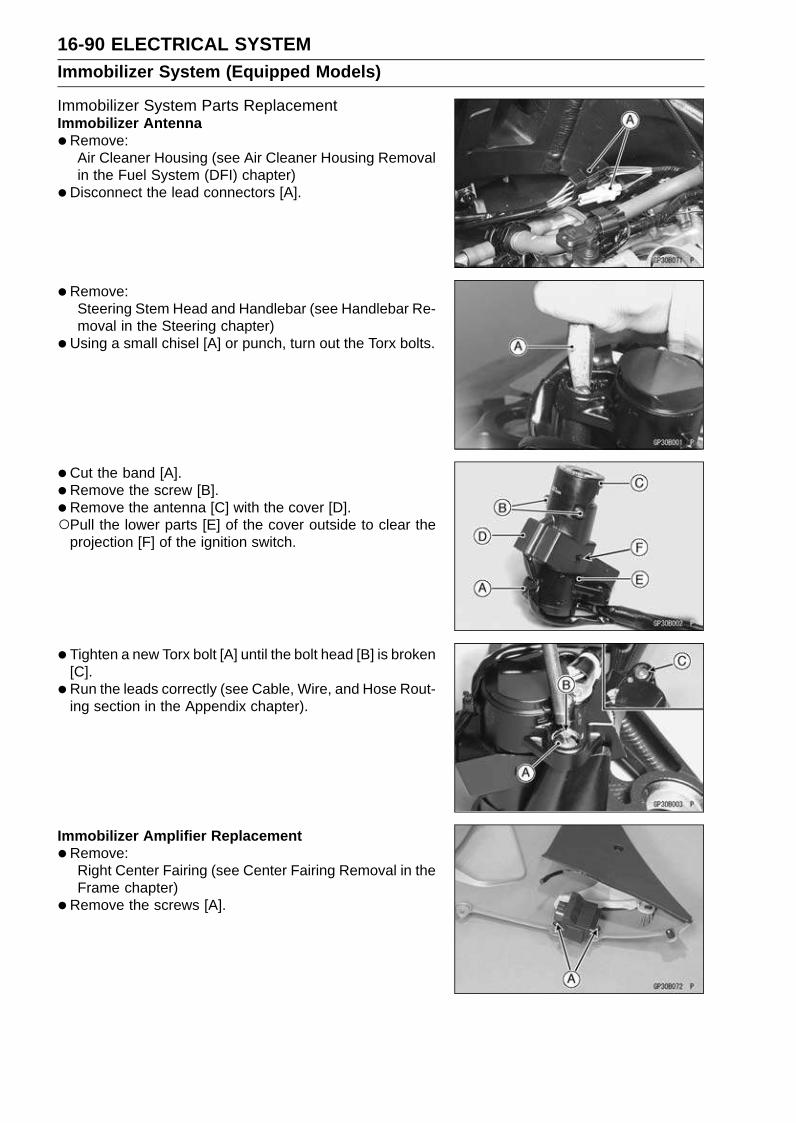
16-90 ELECTRICAL SYSTEMImmobilizer System (Equipped Models)
Immobilizer System Parts ReplacementImmobilizer Antenna
•Remove:Air Cleaner Housing (see Air Cleaner Housing Removalin the Fuel System (DFI) chapter)
•Disconnect the lead connectors [A].
• Remove:Steering Stem Head and Handlebar (see Handlebar Re-moval in the Steering chapter)
•Using a small chisel [A] or punch, turn out the Torx bolts.
• Cut the band [A].
• Remove the screw [B].
• Remove the antenna [C] with the cover [D].Pull the lower parts [E] of the cover outside to clear the
projection [F] of the ignition switch.
• Tighten a new Torx bolt [A] until the bolt head [B] is broken[C].
• Run the leads correctly (see Cable, Wire, and Hose Rout-ing section in the Appendix chapter).
Immobilizer Amplifier Replacement
•Remove:Right Center Fairing (see Center Fairing Removal in theFrame chapter)
•Remove the screws [A].

ELECTRICAL SYSTEM 16-91Immobilizer System (Equipped Models)
ECU (Electric Control Unit) Replacement (for EuropeanModel)
•Remove:Seat Cover (see Seat Cover Removal in the Framechapter)
•Using a small chisel or other suitable tool, turn out thescrews [A].
• Remove the bolt [B] and guard bracket [C].
• Remove the ECU.
•Connect the connectors [A].
• Install:Guard Bracket [A]
CAUTION
Do not pinch the leads.
•Tighten new screws [B] use Kawasaki genuine screws ofwhich threads are coated with locking agent.
Immobilizer Relational Parts Replacement Chart
Failed or Lost Part
MasterKey
(Red)
UserKey
(Black)
IgnitionSwitch
An-tenna
Ampli-fier
ECU
MasterKey
(Red)•
UserKey
(Black)•
IgnitionSwitch •
An-tenna •Ampli-
fier •
*
ECU •* Replacement Part
• Main Replacement Part
Additional Replacement Part

16-92 ELECTRICAL SYSTEMImmobilizer System (Equipped Models)
Immobilizer System Inspection•Refer to the Immobilizer Amplifier and Blank Key Detec-
tion section in the Fuel System (DFI) chapter.
Immobilizer System Circuit
1. ECU2. Ignition Switch3. Immobilizer Amplifier4. Immobilizer Antenna5. Meter Unit6. Fuse Box7. Ignition Fuse 10 A8. ECU Fuse 15 A9. Relay Box
10. ECU Main Relay11. Starter Relay12. Main Fuse 30 A13. Battery 12 V 8 Ah14. Immobilizer/Kawasaki Self-diagnostic System Connector
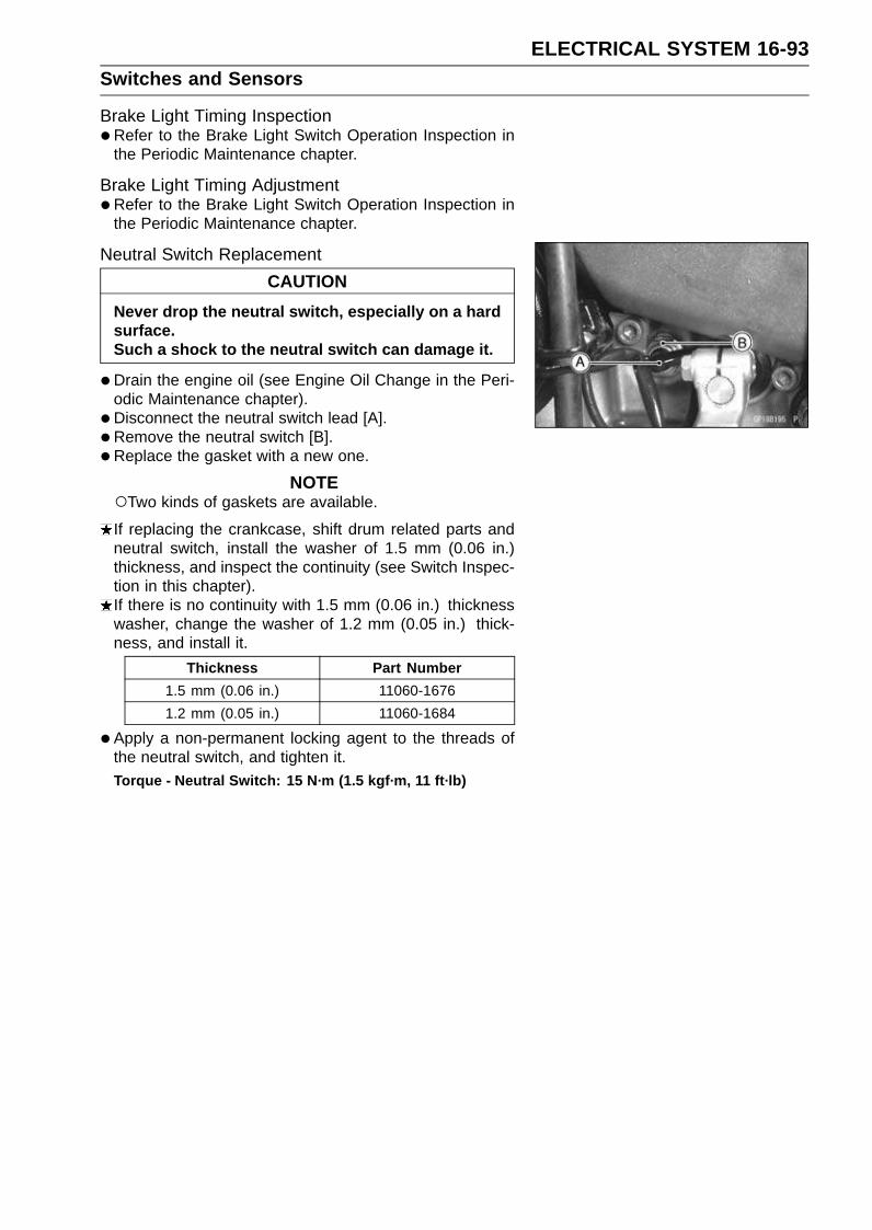
ELECTRICAL SYSTEM 16-93Switches and Sensors
Brake Light Timing Inspection•Refer to the Brake Light Switch Operation Inspection in
the Periodic Maintenance chapter.
Brake Light Timing Adjustment•Refer to the Brake Light Switch Operation Inspection in
the Periodic Maintenance chapter.
Neutral Switch Replacement
CAUTION
Never drop the neutral switch, especially on a hardsurface.Such a shock to the neutral switch can damage it.
•Drain the engine oil (see Engine Oil Change in the Peri-odic Maintenance chapter).
• Disconnect the neutral switch lead [A].
• Remove the neutral switch [B].
• Replace the gasket with a new one.
NOTETwo kinds of gaskets are available.
If replacing the crankcase, shift drum related parts andneutral switch, install the washer of 1.5 mm (0.06 in.)thickness, and inspect the continuity (see Switch Inspec-tion in this chapter).If there is no continuity with 1.5 mm (0.06 in.) thicknesswasher, change the washer of 1.2 mm (0.05 in.) thick-ness, and install it.
Thickness Part Number
1.5 mm (0.06 in.) 11060-1676
1.2 mm (0.05 in.) 11060-1684
•Apply a non-permanent locking agent to the threads ofthe neutral switch, and tighten it.Torque - Neutral Switch: 15 N·m (1.5 kgf·m, 11 ft·lb)

16-94 ELECTRICAL SYSTEMSwitches and Sensors
Switch Inspection•Using a hand tester, check to see that only the con-
nections shown in the table have continuity (about zeroohms).For the handlebar switches and the ignition switch, refer
to the tables in the Wiring Diagram.If the switch has an open or short, repair it or replace itwith a new one.Special Tool - Hand Tester: 57001-1394
Rear Brake Light Switch Connections
Side Stand Switch Connections
Neutral Switch Connections
Oil Pressure Switch Connections*
*: Engine lubrication system is in good condition
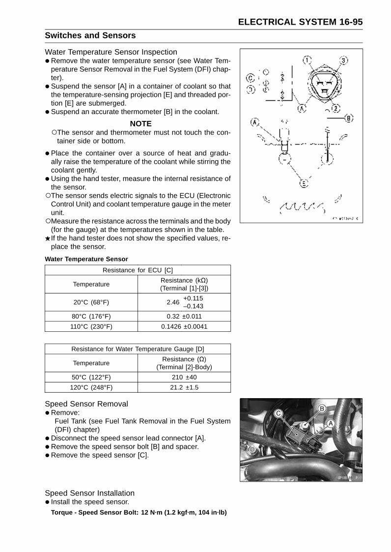
ELECTRICAL SYSTEM 16-95Switches and Sensors
Water Temperature Sensor Inspection•Remove the water temperature sensor (see Water Tem-
perature Sensor Removal in the Fuel System (DFI) chap-ter).
• Suspend the sensor [A] in a container of coolant so thatthe temperature-sensing projection [E] and threaded por-tion [E] are submerged.
• Suspend an accurate thermometer [B] in the coolant.
NOTEThe sensor and thermometer must not touch the con-
tainer side or bottom.
•Place the container over a source of heat and gradu-ally raise the temperature of the coolant while stirring thecoolant gently.
• Using the hand tester, measure the internal resistance ofthe sensor.The sensor sends electric signals to the ECU (Electronic
Control Unit) and coolant temperature gauge in the meterunit.Measure the resistance across the terminals and the body
(for the gauge) at the temperatures shown in the table.If the hand tester does not show the specified values, re-place the sensor.
Water Temperature Sensor
Resistance for ECU [C]
TemperatureResistance (kΩ)(Terminal [1]-[3])
20°C (68°F) 2.46+0.115–0.143
80°C (176°F) 0.32 ±0.011
110°C (230°F) 0.1426 ±0.0041
Resistance for Water Temperature Gauge [D]
TemperatureResistance (Ω)
(Terminal [2]-Body)
50°C (122°F) 210 ±40
120°C (248°F) 21.2 ±1.5
Speed Sensor Removal•Remove:
Fuel Tank (see Fuel Tank Removal in the Fuel System(DFI) chapter)
•Disconnect the speed sensor lead connector [A].
• Remove the speed sensor bolt [B] and spacer.
•Remove the speed sensor [C].
Speed Sensor Installation• Install the speed sensor.
Torque - Speed Sensor Bolt: 12 N·m (1.2 kgf·m, 104 in·lb)
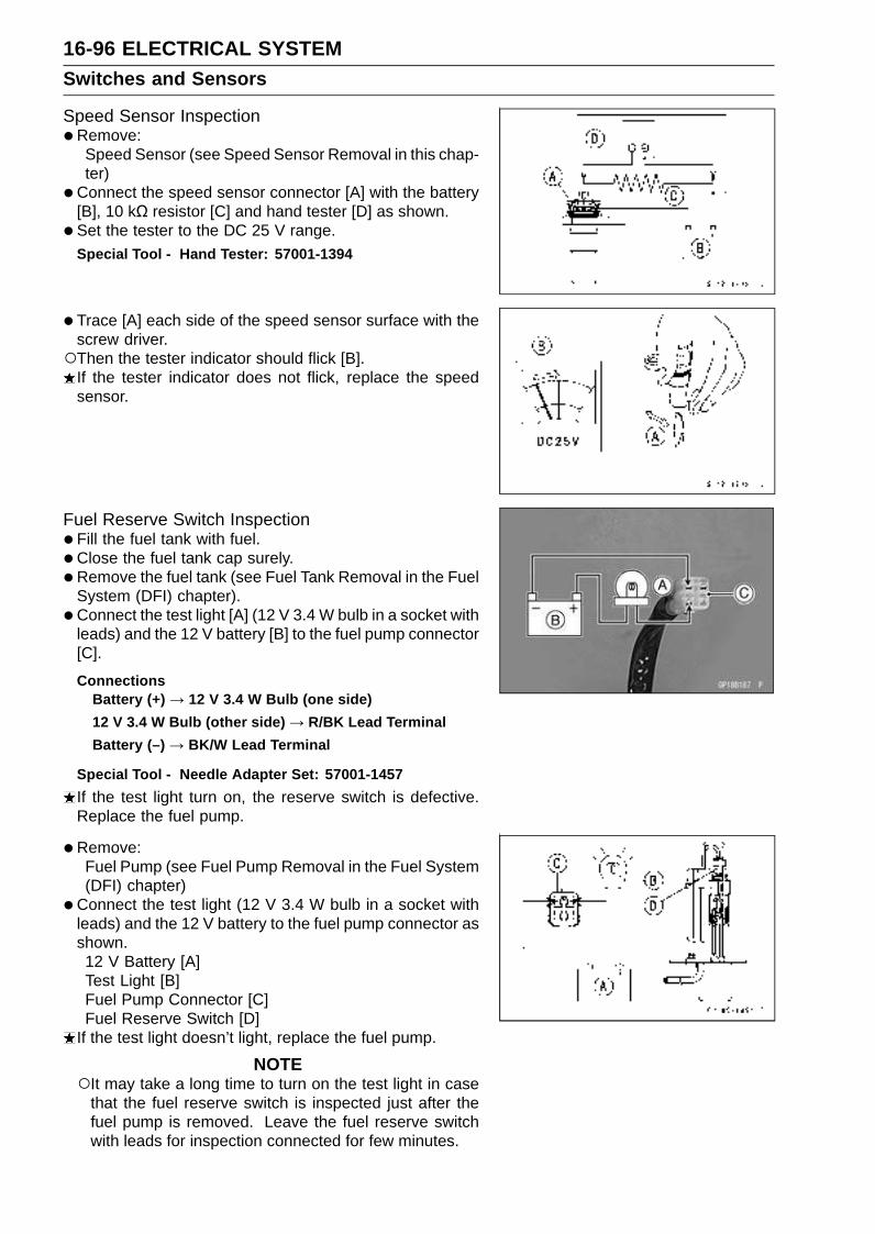
16-96 ELECTRICAL SYSTEMSwitches and Sensors
Speed Sensor Inspection•Remove:
Speed Sensor (see Speed Sensor Removal in this chap-ter)
•Connect the speed sensor connector [A] with the battery[B], 10 kΩ resistor [C] and hand tester [D] as shown.
• Set the tester to the DC 25 V range.Special Tool - Hand Tester: 57001-1394
•Trace [A] each side of the speed sensor surface with thescrew driver.Then the tester indicator should flick [B].
If the tester indicator does not flick, replace the speedsensor.
Fuel Reserve Switch Inspection•Fill the fuel tank with fuel.
• Close the fuel tank cap surely.
• Remove the fuel tank (see Fuel Tank Removal in the FuelSystem (DFI) chapter).
• Connect the test light [A] (12 V 3.4 W bulb in a socket withleads) and the 12 V battery [B] to the fuel pump connector[C].
ConnectionsBattery (+) → 12 V 3.4 W Bulb (one side)
12 V 3.4 W Bulb (other side) → R/BK Lead Terminal
Battery (–) → BK/W Lead Terminal
Special Tool - Needle Adapter Set: 57001-1457
If the test light turn on, the reserve switch is defective.Replace the fuel pump.
•Remove:Fuel Pump (see Fuel Pump Removal in the Fuel System(DFI) chapter)
•Connect the test light (12 V 3.4 W bulb in a socket withleads) and the 12 V battery to the fuel pump connector asshown.12 V Battery [A]Test Light [B]Fuel Pump Connector [C]Fuel Reserve Switch [D]
If the test light doesn’t light, replace the fuel pump.
NOTEIt may take a long time to turn on the test light in case
that the fuel reserve switch is inspected just after thefuel pump is removed. Leave the fuel reserve switchwith leads for inspection connected for few minutes.
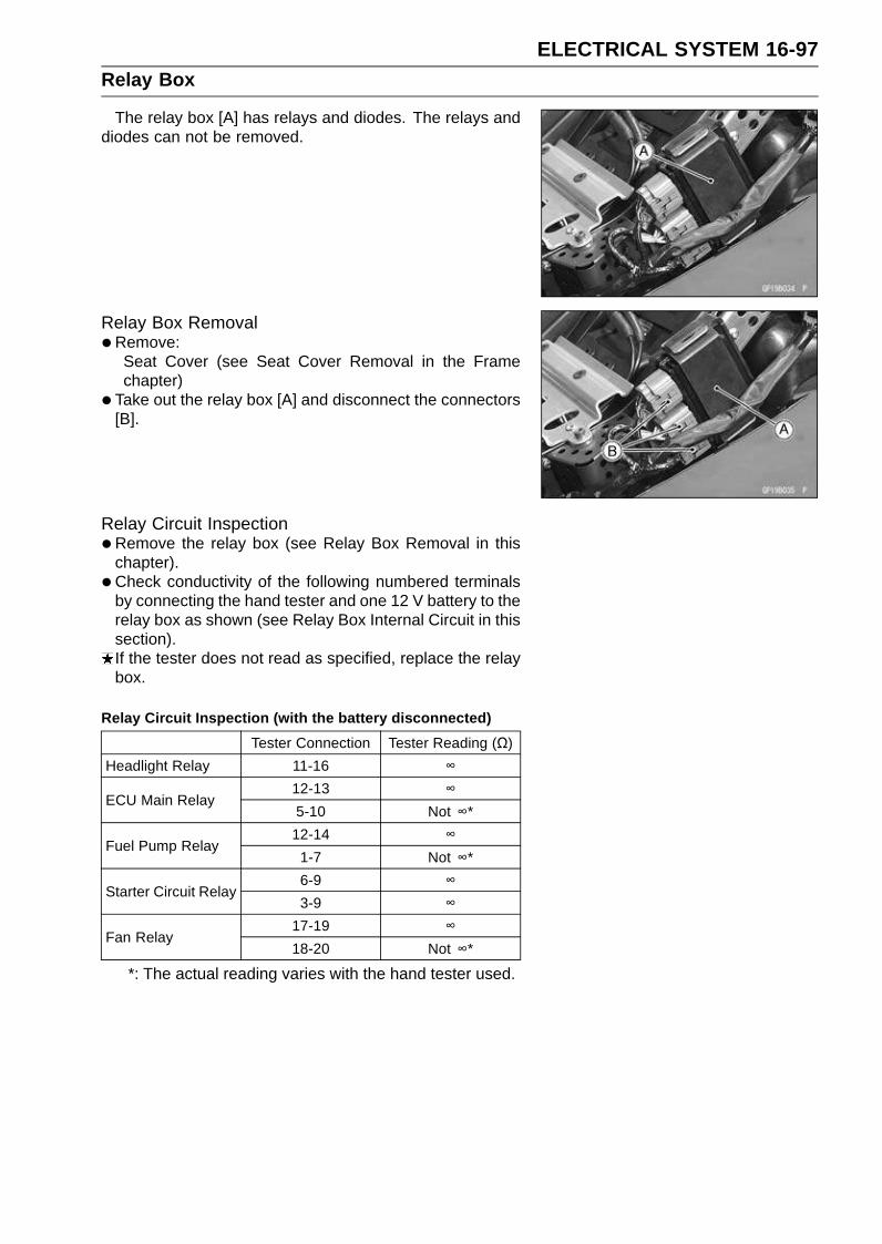
ELECTRICAL SYSTEM 16-97Relay Box
The relay box [A] has relays and diodes. The relays anddiodes can not be removed.
Relay Box Removal•Remove:
Seat Cover (see Seat Cover Removal in the Framechapter)
• Take out the relay box [A] and disconnect the connectors[B].
Relay Circuit Inspection•Remove the relay box (see Relay Box Removal in this
chapter).
• Check conductivity of the following numbered terminalsby connecting the hand tester and one 12 V battery to therelay box as shown (see Relay Box Internal Circuit in thissection).If the tester does not read as specified, replace the relaybox.
Relay Circuit Inspection (with the battery disconnected)
Tester Connection Tester Reading (Ω)
Headlight Relay 11-16 ∞12-13 ∞
ECU Main Relay5-10 Not ∞*
12-14 ∞Fuel Pump Relay
1-7 Not ∞*
6-9 ∞Starter Circuit Relay
3-9 ∞17-19 ∞
Fan Relay18-20 Not ∞*
*: The actual reading varies with the hand tester used.
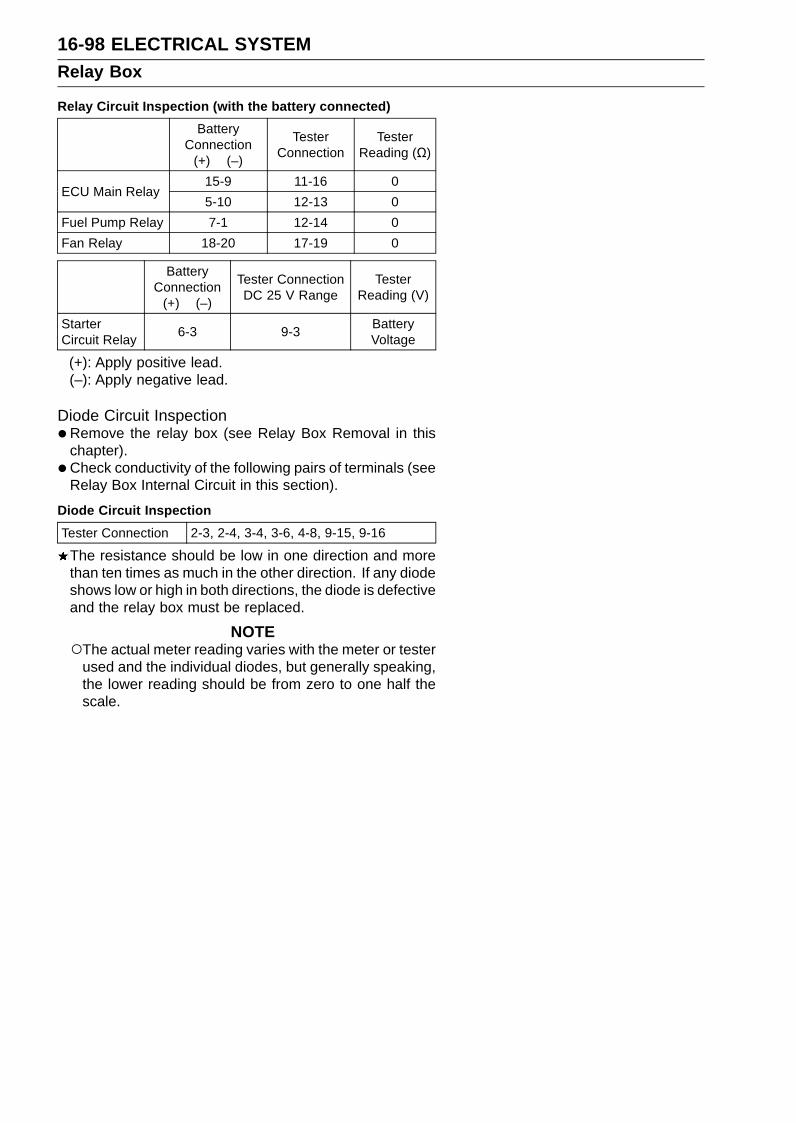
16-98 ELECTRICAL SYSTEMRelay Box
Relay Circuit Inspection (with the battery connected)
BatteryConnection
(+) (–)
TesterConnection
TesterReading (Ω)
15-9 11-16 0ECU Main Relay
5-10 12-13 0
Fuel Pump Relay 7-1 12-14 0
Fan Relay 18-20 17-19 0
BatteryConnection
(+) (–)
Tester ConnectionDC 25 V Range
TesterReading (V)
StarterCircuit Relay
6-3 9-3BatteryVoltage
(+): Apply positive lead.(–): Apply negative lead.
Diode Circuit Inspection•Remove the relay box (see Relay Box Removal in this
chapter).
• Check conductivity of the following pairs of terminals (seeRelay Box Internal Circuit in this section).
Diode Circuit Inspection
Tester Connection 2-3, 2-4, 3-4, 3-6, 4-8, 9-15, 9-16
The resistance should be low in one direction and morethan ten times as much in the other direction. If any diodeshows low or high in both directions, the diode is defectiveand the relay box must be replaced.
NOTEThe actual meter reading varies with the meter or tester
used and the individual diodes, but generally speaking,the lower reading should be from zero to one half thescale.
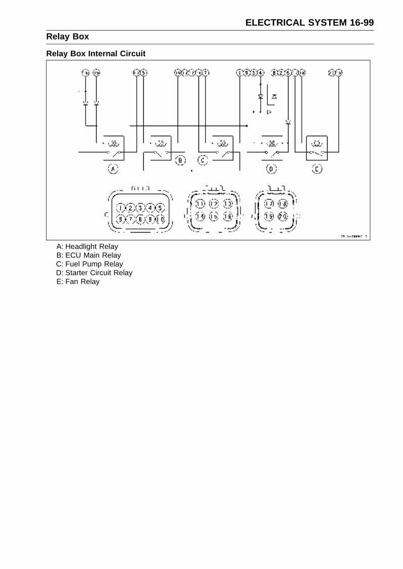
ELECTRICAL SYSTEM 16-99Relay Box
Relay Box Internal Circuit
A: Headlight RelayB: ECU Main RelayC: Fuel Pump RelayD: Starter Circuit RelayE: Fan Relay

16-100 ELECTRICAL SYSTEMFuse
30 A Main Fuse Removal•Remove:
Left Side Cover (see Left Side Cover Removal in theFrame chapter)30 A Main Fuse Connector [A]
• Pull out the main fuse [A] from the starter relay with needlenose pliers.
Fuse Box Fuse Removal•Remove the rear seat (see Rear Seat Removal in the
Frame chapter).
• Push the hook [A] to lift up the lid [B].
• Pull the fuses [A] straight out of the fuse box with needlenose pliers.
15 A ECU Fuse Removal•Remove:
Rear Seat (see Rear Seat Removal in the Frame chap-ter)
• Pull the hook [A] to lift up the lid [B]
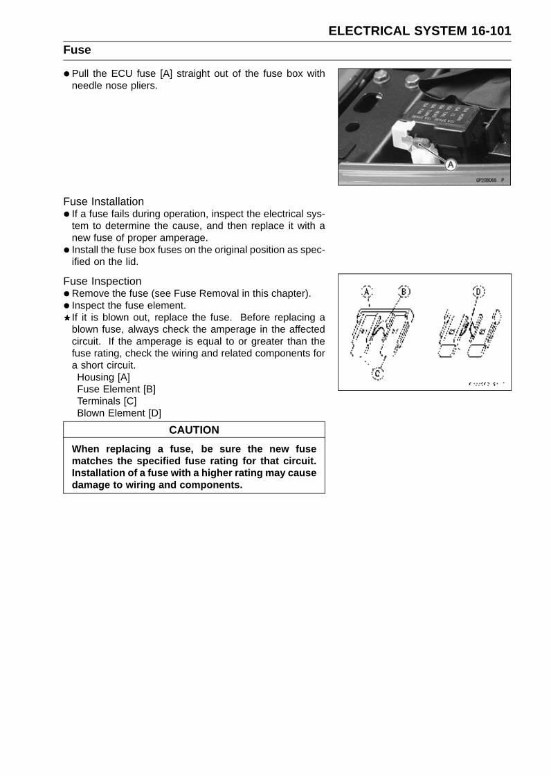
ELECTRICAL SYSTEM 16-101Fuse
•Pull the ECU fuse [A] straight out of the fuse box withneedle nose pliers.
Fuse Installation• If a fuse fails during operation, inspect the electrical sys-
tem to determine the cause, and then replace it with anew fuse of proper amperage.
• Install the fuse box fuses on the original position as spec-ified on the lid.
Fuse Inspection•Remove the fuse (see Fuse Removal in this chapter).
• Inspect the fuse element.If it is blown out, replace the fuse. Before replacing ablown fuse, always check the amperage in the affectedcircuit. If the amperage is equal to or greater than thefuse rating, check the wiring and related components fora short circuit.Housing [A]Fuse Element [B]Terminals [C]Blown Element [D]
CAUTION
When replacing a fuse, be sure the new fusematches the specified fuse rating for that circuit.Installation of a fuse with a higher rating may causedamage to wiring and components.

APPENDIX 17-1
17
Appendix
Table of Contents
Cable, Wire, and Hose Routing .............................................................................................. 17-2Troubleshooting Guide ........................................................................................................... 17-28

17-2 APPENDIXCable, Wire, and Hose Routing

APPENDIX 17-3Cable, Wire, and Hose Routing
1. Meter Connector2. Left Switch Housing Lead Connector3. Front Right Turn Signal Light Connector4. Headlight Harness Connector5. Immobilizer Amplifier (Equipped Models)6. Right Switch Housing Lead Connector7. Horn Lead Connectors8. Clamp the horn lead.9. Camshaft Position Sensor Lead Connector
10. Immobilizer Antenna (Equipped Models)11. Ignition Switch Lead Connector12. Clamp13. Radiator Fan Lead Connector14. Stick Coil #1 Connector15. Stick Coil #2 Connector16. Stick Coil #3 Connector17. Stick Coil #4 Connector18. White Mark19. Engine Ground20. Subthrottle Sensor Connector21. Inlet Air Pressure Sensor Connector22. Atomospheric Pressure Sensor Connector23. Main Harness24. Secondary Fuel Injector #1 Connector25. Secondary Fuel Injector #2 Connector26. Secondary Fuel Injector #3 Connector27. Secondary Fuel Injector #4 Connector28. Inlet Air Temperature Sensor Connector29. Main Throttle Sensor Connector30. Primary Fuel Injector #1 Connector31. Primary Fuel Injector #2 Connector32. Primary Fuel Injector #3 Connector33. Primary Fuel Injector #4 Connector34. Water Temperature Sensor Connector35. View A36. Clamp37. Clamp38. Regulator/Rectifier Lead Connector39. Subthrottle Valve Actuator Lead Connector40. Speed Sensor Connector41. Side Stand Switch Lead Connector42. Engine Harness43. Rear Brake Light Switch Lead Connector44. Clamp45. Frame Ground

17-4 APPENDIXCable, Wire, and Hose Routing
APPENDIX 17-5Cable, Wire, and Hose Routing
1. Fuel Pump Lead2. Fuel Tank3. Frame4. Clamp5. Immobilizer/Kawasaki Diagnosis System Connector6. Fuel Pump Lead Connector7. Vehicle-down Sensor Lead Connector8. Clamp9. Self-diagnosis Indicator Terminal
10. Exhaust Butterfly Valve Actuator Lead Connector11. ECU Connectors12. Seat Lock Cable13. Relay Box14. Exhaust Butterfly Valve Cable (Accelerator)15. Exhaust Butterfly Valve Cable (Decelerator)16. Fuse Box17. Turn Signal Relay Connector18. Licence Plate Light Connector19. Rear Left Turn Signal Light Connector20. Rear Right Turn Signal Light Connector21. Tail/Brake Light Connector22. Clamp the together with tail/brake and rear turn signal light lead.23. Clamp

17-6 APPENDIXCable, Wire, and Hose Routing

APPENDIX 17-7Cable, Wire, and Hose Routing
1. Battery Positive Terminal2. Starter Relay3. Battery Negative Terminal4. Clamp5. Relay Box6. Run the seat lock cable into the relay box bracket.7. Fuse Box8. Turn Signal Relay9. Clamp
10. Rear Right Turn Signal Light Connector11. Tail/Brake Light Connector12. Run the licence plate light and rear left turn signal light lead into the left turn signal light cover.13. Clamp14. Licence Plate Light Lead15. Rear Left Turn Signal Light Connector16. Licence Plate Light Connector17. Left Side View18. Run the rear brake light switch lead between front frame and cover.19. Cover20. Right Side View

17-8 APPENDIXCable, Wire, and Hose Routing
APPENDIX 17-9Cable, Wire, and Hose Routing
1. Meter Connector2. Clamp the meter connector and front turn signal light connector.3. Front Left Turn Signal Light Connector4. Left Switch Housing Lead5. United States, Canada and California Model only6. Clamps7. Headlight Connector8. Immobilizer Amplifier (Equipped Models)9. Front Right Turn Signal Light Connector
10. Front Right Turn Signal Light Connector11. Right Switch Housing Lead12. Front Brake Hose13. Band14. Band15. Left Switch Housing Lead16. Approx. 72 mm (2.8 in.)17. Right Switch Housing Lead Connector18. Band19. Run the horn lead between frame and radiator.
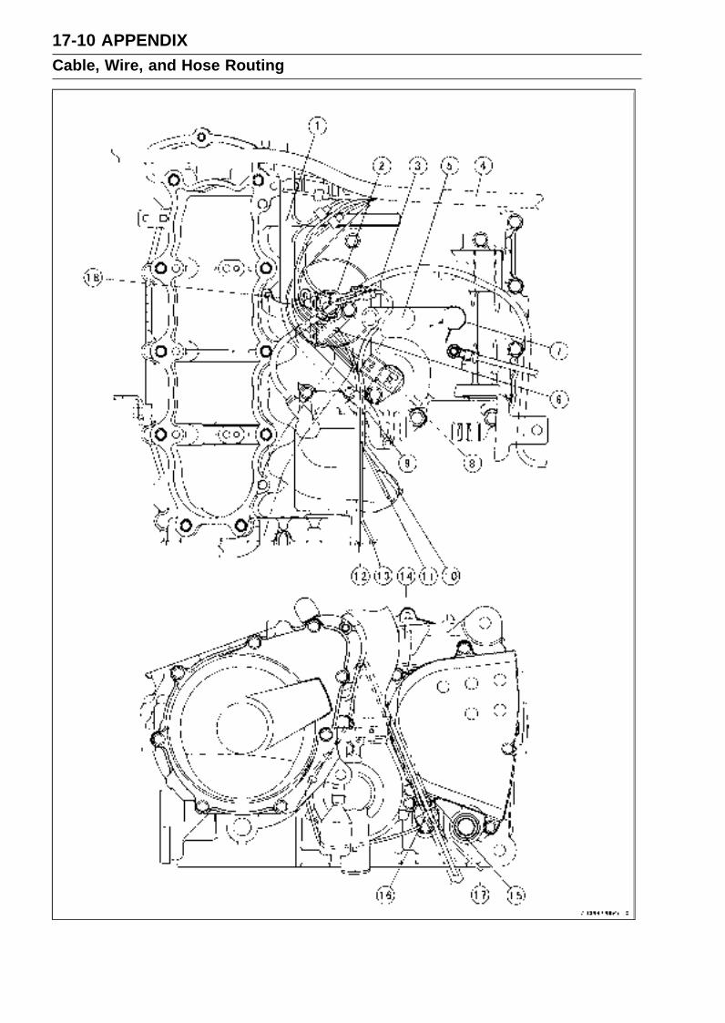
17-10 APPENDIXCable, Wire, and Hose Routing
APPENDIX 17-11Cable, Wire, and Hose Routing
1. Reserve Return Hose2. Clamp3. Starter Motor Cable4. Main Harness5. Run the harnesses under the breather hose.6. Clamp7. Clamp8. Speed Sensor9. Force the harness into between the bosses of the upper crankcase.
10. Regulator/Rectifier Lead11. Side Stand Switch Lead12. Alternator Lead13. Neutral Switch Lead14. Reserve Tank Over Flow Hose15. Clamp the regulator/rectifier lead together with the fuel tank drain hose and reserve tank over
flow hose.16. Clamp the side stand switch lead.17. Adjust the clamp position so that the side stand lead does not loosen.18. Run the alternator lead under the starter motor cable.

17-12 APPENDIXCable, Wire, and Hose Routing

APPENDIX 17-13Cable, Wire, and Hose Routing
1. Insert the holes of heat insulation rubber plate in to the radiator stay.2. Run the fan lead from the holes of heat insulation rubber plate.3. After install the holes of heat insulation rubber plate, clamp the lead as shown.4. Clamp the leads so that the heat insulation rubber plate does not fit the radiator.5. Heat Insulation Rubber Plate6. Insert the holes of heat insulation rubber plate into the radiator cap.7. Immobilizer Antenna Lead (Equipped Models)8. Ignition Switch Lead9. Position the fuel tank drain hose outside of the lower fairing.
10. Fuel Tank Drain Hose11. Clamp the regulator/rectifier lead together with the fuel tank drain hose and reserve tank over
flow hose.12. Clamp13. Clamp14. To the Oil Pressure Switch
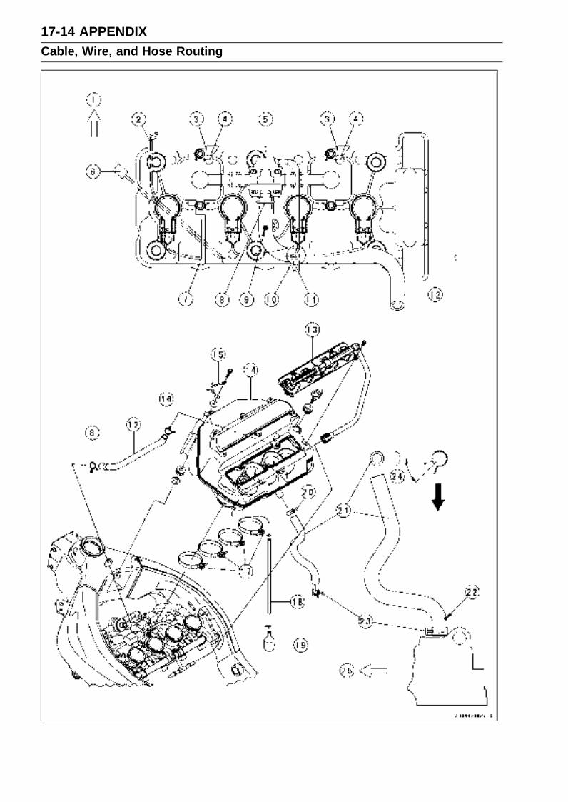
17-14 APPENDIXCable, Wire, and Hose Routing
APPENDIX 17-15Cable, Wire, and Hose Routing
1. Front2. Horn Lead3. Clamps4. Fit the clamp to the air suction valve cover.5. Vacuum Switch Valve6. Radiator Fan Lead7. Clamp the together with radiator fan lead and horn lead.8. Position the clamp pinch head facing the cylinder head.9. Position the paint mark as shown.
10. Run the vacuum switch valve hose over the harnesses.11. From Throttle Body Assy12. Vacuum Switch Valve Hose (To the Air Cleaner Housing)13. Nozzle Assy14. Air Cleaner Housing15. Clamp (For Throttle and Clutch Cable)16. Clamp (Position the clamp pinch head facing right side.)17. Air Cleaner Housing Holder Clamp18. Tube19. Oil Catch Tank20. Clamp (Position the clamp pinch head facing right side.)21. Blowby Tube22. Face the paint mark backward.23. Clamp24. 0 ∼ 10°25. Front

17-16 APPENDIXCable, Wire, and Hose Routing
APPENDIX 17-17Cable, Wire, and Hose Routing
1. Radiator2. Clamp3. Radiator Over Flow Hose4. Clamp5. Radiator Coolant Return Hose6. To the Cylinder Head7. Install the bolt head of the hose clamp as shown.8. Insert radiator hose to the corner position of the radiator pipe.9. Install the bolt head of the hose clamp as shown.
10. Hose11. To the Water Pump12. Hose13. Oil Cooler14. Hose15. Left Heat Insulation Damper16. Right Heat Insulation Damper17. First run the radiator coolant return hose under the clutch cable. Them run it over the main
harness left side, radiator over flow hose and camshaft chain tensioner. Next run it cylinder sidemore than the other harness.
18. Run the radiator over flow hose under the clutch cable, main harness and radiator coolant returnhose.
19. Main Harness20. Clutch Cable21. Right Side View22. Clamp23. Reserve Tank Drain Hose24. Coolant Reserve Tank

17-18 APPENDIXCable, Wire, and Hose Routing
APPENDIX 17-19Cable, Wire, and Hose Routing
1. Hose Clamp2. Hose Clamp3. Hose4. Oil Cooler5. Oil Filter6. White Mark7. Clamp8. Hose9. Clamp
10. Radiator Hose11. Front View12. Align the paint mark and embossed line.13. Face the paint mark upward.14. Install the clamp as shown.15. Install the clamp as shown.16. Clamp (California Model only)17. Hose Clamp18. Hose Clamp19. Hose Clamp20. Align the paint mark and embossed line.21. Hose Clamp22. Align the paint mark and embossed line.23. Neutral Switch Lead24. Align the paint mark and embossed line.25. Install the bolt head of the hose clamps direction as shown illustration.

17-20 APPENDIXCable, Wire, and Hose Routing

APPENDIX 17-21Cable, Wire, and Hose Routing
1. Main Harness2. Run the clutch cable over the throttle cable.3. Run the throttle cable over the front master cylinder.4. Throttle Cables5. Run the clutch and throttle cable into the clamp.6. Clamp (Tighten the clamp with air cleaner housing.)7. Clutch Cable8. Run the throttle cable under the clamp.9. Throttle Cable (Accelerator)
10. Throttle Cable (Decelerator)11. Fit the frame as shown.12. Run the clutch cable over the main harness.13. Run the main harness under the clutch cable.14. Right Side View
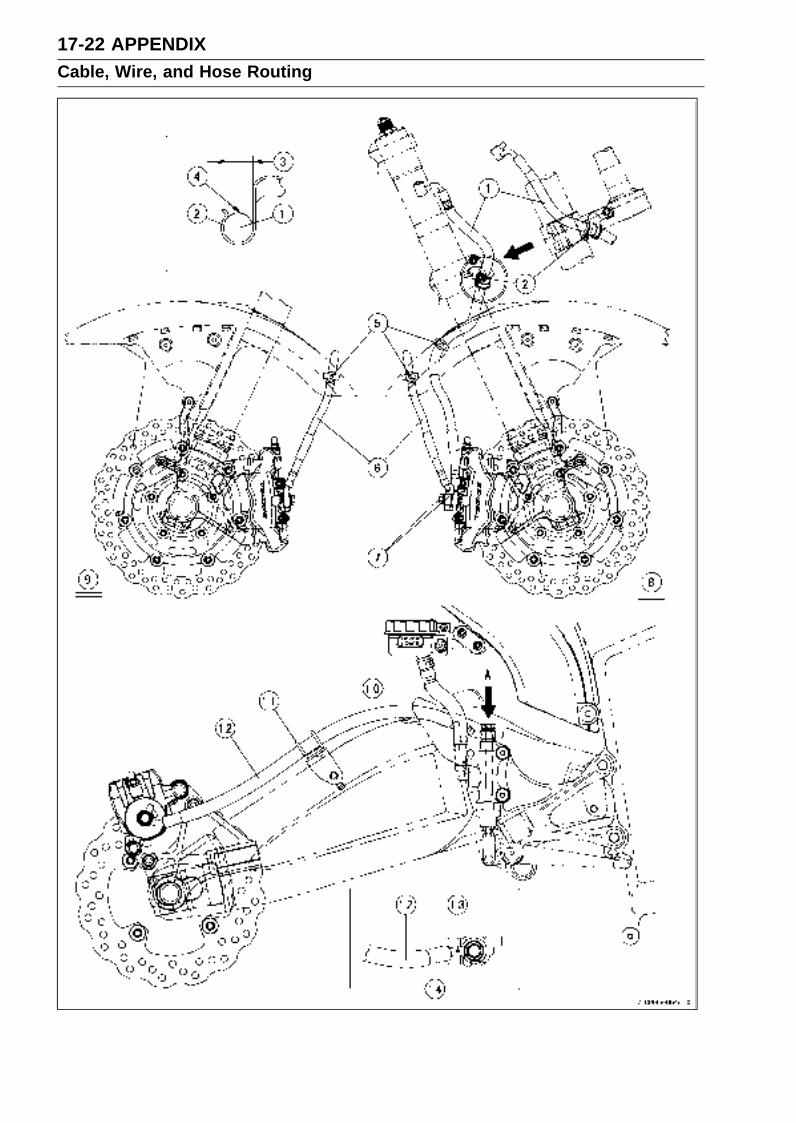
17-22 APPENDIXCable, Wire, and Hose Routing

APPENDIX 17-23Cable, Wire, and Hose Routing
1. Brake Hose2. Clamp3. Install the brake hose so that align the mark with the center of opening of the clamp.4. Mark5. Clamps6. Brake Hose7. Face the paint mark outside.8. Right Side View9. Left Side View
10. Brake Hose11. Clamp12. Brake Hose13. Face the paint mark outside.14. View A
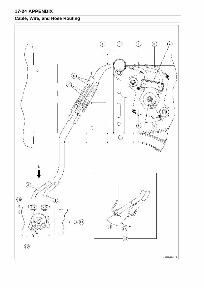
17-24 APPENDIXCable, Wire, and Hose Routing
APPENDIX 17-25Cable, Wire, and Hose Routing
1. Rear Frame2. Exhaust Butterfly Valve Cable (Accelerator)3. Exhaust Butterfly Valve Cable (Decelerator)4. Holder5. Position the exhaust butterfly valve cable (accelerator) over the exhaust butterfly valve cable
(decelerator).6. Dust Cover7. Adjusters8. Exhaust Butterfly Valve Actuator9. 41.7° ±7° (Original Position of Pulley)
10. 6 mm (0.24 in.)11. Front12. Muffler Body13. Approx. 57°14. Approx. 42°15. View A

17-26 APPENDIXCable, Wire, and Hose Routing
California Model

APPENDIX 17-27Cable, Wire, and Hose Routing
1. White Marks2. Hose (Green)3. View A4. White Marks5. Clamp6. Position the red hose under the blue hose, and clamp the them.7. Run the green hose over the harness.8. Canister9. Hose (White)
10. Hose (Blue)11. Hose (Red)12. Hose (Blue)13. Run the blue hose outside of the frame.14. Separator15. Approx. 45°16. Face the paint mark left side.17. Run the green hose forward of the engine mount.18. To the Fitting of the Throttle Body #419. To the Fuel Tank (Blue Hose)20. To the Fuel Tank (Red Hose)21. Bolt22. Install the nut to the center fairing.23. Canister Bracket24. Bolt25. Install the nut to the frame.26. Bolt27. Install the nut to the center fairing.28. Separator Bracket

17-28 APPENDIXTroubleshooting Guide
NOTERefer to the Fuel System chapter for most
of DFI trouble shooting guide.This is not an exhaustive list, giving every
possible cause for each problem listed. Itis meant simply as a rough guide to assistthe troubleshooting for some of the morecommon difficulties.
Engine Doesn’t Start, StartingDifficulty:
Starter motor not rotating:Starter lockout switch or neutral switch trou-
bleStarter motor troubleBattery voltage lowStarter relay not contacting or operatingStarter button not contactingWiring open or shortedIgnition switch troubleEngine stop switch troubleFuse blown
Starter motor rotating but engine doesn’tturn over:
Immobilizer system troubleStarter clutch troubleVehicle-down sensor (DFI) coming off
Engine won’t turn over:Valve seizureValve lifter seizureCylinder, piston seizureCrankshaft seizureConnecting rod small end seizureConnecting rod big end seizureTransmission gear or bearing seizureCamshaft seizureStarter idle gear seizure
No fuel flow:No fuel in tankFuel pump troubleFuel tank air vent obstructedFuel filter cloggedFuel line clogged
No spark; spark weak:Vehicle-down sensor (DFI) coming offIgnition switch not ONEngine stop switch turned OFFClutch lever not pulled in or gear not in neu-
tralBattery voltage lowImmobilizer system troubleSpark plug dirty, broken, or gap malad-
justedStick coil shorted or not in good contactStick coil troubleSpark plug incorrectIC igniter in ECU trouble
Camshaft position sensor troubleNeutral, starter lockout, or side stand switch
troubleCrankshaft sensor troubleIgnition switch or engine stop switch
shortedWiring shorted or openFuse blown
Fuel/air mixture incorrect:Bypass screw and/or idle adjusting screw
maladjustedAir passage cloggedAir cleaner clogged, poorly sealed, or miss-
ingCompression Low:
Spark plug looseCylinder head not sufficiently tightened
downNo valve clearanceCylinder, piston wornPiston ring bad (worn, weak, broken, or
sticking)Piston ring/groove clearance excessiveCylinder head gasket damagedCylinder head warpedValve spring broken or weakValve not seating properly (valve bent,
worn, or carbon accumulation on theseating surface)
Poor Running at Low Speed:Spark weak:
Battery voltage lowSpark plug dirty, broken, or maladjustedStick coil wiring troubleStick coil not in good contactSpark plug incorrectIC igniter in ECU troubleCamshaft position sensor troubleCrankshaft sensor troubleStick coil troubleImmobilizer system trouble
Fuel/air mixture incorrect:Bypass screw maladjustedAir passage cloggedAir bleed pipe bleed holes cloggedPilot passage cloggedAir cleaner clogged, poorly sealed, or miss-
ingFuel tank air vent obstructedFuel pump troubleThrottle body assy holder looseAir cleaner duct loose
Compression low:Spark plug looseCylinder head not sufficiently tightened
down

APPENDIX 17-29Troubleshooting Guide
No valve clearanceCylinder, piston wornPiston ring bad (worn, weak, broken, or
sticking)Piston ring/groove clearance excessiveCylinder head warpedCylinder head gasket damagedValve spring broken or weakValve not seating properly (valve bent,
worn, or carbon accumulation on theseating surface)
Other:IC igniter in ECU troubleThrottle body assy not synchronizingEngine oil viscosity too highDrive train troubleBrake draggingAir suction valve troubleVacuum switch valve troubleEngine overheatingClutch slipping
Poor Running or No Power at HighSpeed:
Firing incorrect:Spark plug dirty, broken, or maladjustedStick coil wiring troubleStick coil not in good contactSpark plug incorrectCamshaft position sensor troubleIC igniter in ECU troubleCrankshaft sensor troubleStick coil trouble
Fuel/air mixture incorrect:Air cleaner clogged, poorly sealed, or miss-
ingAir cleaner O-ring damagedAir cleaner duct looseWater or foreign matter in fuelThrottle body assy holder looseFuel to injector insufficientFuel tank air vent obstructedFuel line cloggedFuel pump trouble
Compression low:Spark plug looseCylinder head not sufficiently tightened
downNo valve clearanceCylinder, piston wornPiston ring bad (worn, weak, broken, or
sticking)Piston ring/groove clearance excessiveCylinder head gasket damagedCylinder head warpedValve spring broken or weak
Valve not seating properly (valve bent,worn, or carbon accumulation on theseating surface.)
Knocking:Carbon built up in combustion chamberFuel poor quality or incorrectSpark plug incorrectIC igniter in ECU troubleCamshaft position sensor troubleCrankshaft sensor trouble
Miscellaneous:Throttle valve won’t fully openBrake draggingClutch slippingEngine overheatingEngine oil level too highEngine oil viscosity too highDrive train troubleAir suction valve troubleVacuum switch valve troubleCatalytic converter melt down due to muffler
overheating (KLEEN)
Overheating:Firing incorrect:
Spark plug dirty, broken, or maladjustedSpark plug incorrectIC igniter in ECU trouble
Muffler overheating:For KLEEN, do not run the engine even if
with only one cylinder misfiring or poorrunning (Request the nearest service fa-cility to correct it)
For KLEEN, do not push-start with a deadbattery (Connect another full-chargedbattery with jumper cables, and start theengine using the electric starter)
For KLEEN, do not start the engine undermisfire due to spark plug fouling or poorconnection of the stick coil
For KLEEN, do not coast the motorcyclewith the ignition switch off (Turn the igni-tion switch ON and run the engine)
IC igniter in ECU troubleFuel/air mixture incorrect:
Throttle body assy holder looseAir cleaner duct looseAir cleaner poorly sealed, or missingAir cleaner O-ring damagedAir cleaner clogged
Compression high:Carbon built up in combustion chamber
Engine load faulty:Clutch slippingEngine oil level too highEngine oil viscosity too highDrive train trouble

17-30 APPENDIXTroubleshooting Guide
Brake draggingLubrication inadequate:
Engine oil level too lowEngine oil poor quality or incorrect
Oil cooler incorrect:Oil cooler clogged
Gauge incorrect:Water temperature gauge brokenWater temperature sensor broken
Coolant incorrect:Coolant level too lowCoolant deterioratedWrong coolant mixed ratio
Cooling system component incorrect:Radiator fin damagedRadiator cloggedThermostat troubleRadiator cap troubleRadiator fan switch troubleRadiator fan relay troubleFan motor brokenFan blade damagedWater pump not turningWater pump impeller damaged
Over Cooling:Gauge incorrect:
Water temperature gauge brokenWater temperature sensor broken
Cooling system component incorrect:Radiator fan switch troubleThermostat trouble
Clutch Operation Faulty:Clutch slipping:
Friction plate worn or warpedSteel plate worn or warpedClutch spring broken or weakClutch hub or housing unevenly wornNo clutch lever playClutch inner cable troubleClutch release mechanism trouble
Clutch not disengaging properly:Clutch plate warped or too roughClutch spring compression unevenEngine oil deterioratedEngine oil viscosity too highEngine oil level too highClutch housing frozen on drive shaftClutch hub nut looseClutch hub spline damagedClutch friction plate installed wrongClutch lever play excessiveClutch release mechanism trouble
Gear Shifting Faulty:Doesn’t go into gear; shift pedal doesn’treturn:
Clutch not disengagingShift fork bent or seizedGear stuck on the shaftGear positioning lever bindingShift return spring weak or brokenShift return spring pin looseShift mechanism arm spring brokenShift mechanism arm brokenShift pawl broken
Jumps out of gear:Shift fork ear worn, bentGear groove wornGear dogs and/or dog holes wornShift drum groove wornGear positioning lever spring weak or bro-
kenShift fork guide pin wornDrive shaft, output shaft, and/or gear
splines wornOvershifts:
Gear positioning lever spring weak or bro-ken
Shift mechanism arm spring broken
Abnormal Engine Noise:Knocking:
IC igniter in ECU troubleCarbon built up in combustion chamberFuel poor quality or incorrectSpark plug incorrectOverheating
Piston slap:Cylinder/piston clearance excessiveCylinder, piston wornConnecting rod bentPiston pin, piston pin hole worn
Valve noise:Valve clearance incorrectValve spring broken or weakCamshaft bearing wornValve lifter worn
Other noise:Connecting rod small end clearance exces-
siveConnecting rod big end clearance exces-
sivePiston ring/groove clearance excessivePiston ring worn, broken, or stuckPiston ring groove wornPiston seizure, damageCylinder head gasket leakingExhaust pipe leaking at cylinder head con-
nectionCrankshaft runout excessive

APPENDIX 17-31Troubleshooting Guide
Engine mount looseCrankshaft bearing wornPrimary gear worn or chippedCamshaft chain tensioner troubleCamshaft chain, sprocket, guide wornAir suction valve damagedVacuum switch valve damagedAlternator rotor looseCatalytic converter melt down due to muffler
overheating (KLEEN)
Abnormal Drive Train Noise:Clutch noise:
Clutch damper weak or damagedClutch housing/friction plate clearance ex-
cessiveClutch housing gear wornWrong installation of outside friction plate
Transmission noise:Bearings wornTransmission gear worn or chippedMetal chips jammed in gear teethEngine oil insufficient
Drive line noise:Drive chain adjusted improperlyDrive chain wornRear and/or engine sprocket wornChain lubrication insufficientRear wheel misaligned
Abnormal Frame Noise:Front fork noise:
Oil insufficient or too thinSpring weak or broken
Rear shock absorber noise:Shock absorber damaged
Disc brake noise:Pad installed incorrectlyPad surface glazedDisc warpedCaliper trouble
Other noise:Bracket, nut, bolt, etc. not properly
mounted or tightened
Oil Pressure Warning Light Goes On:Engine oil pump damagedEngine oil screen cloggedEngine oil filter cloggedEngine oil level too lowEngine oil viscosity too lowCamshaft bearing wornCrankshaft bearing wornOil pressure switch damagedWiring faultyRelief valve stuck open
O-ring at the oil passage in the crankcasedamaged
Exhaust Smokes Excessively:White smoke:
Piston oil ring wornCylinder wornValve oil seal damagedValve guide wornEngine oil level too high
Black smoke:Air cleaner clogged
Brown smoke:Air cleaner duct looseAir cleaner O-ring damagedAir cleaner poorly sealed or missing
Handling and/or StabilityUnsatisfactory:
Handlebar hard to turn:Cable routing incorrectHose routing incorrectWiring routing incorrectSteering stem nut too tightSteering stem bearing damagedSteering stem bearing lubrication inade-
quateSteering stem bentTire air pressure too low
Handlebar shakes or excessively vibrates:Tire wornSwingarm pivot bearing wornRim warped, or not balancedWheel bearing wornHandlebar bolt looseSteering stem nut looseFront, rear axle runout excessiveEngine mounting bolt loose
Handlebar pulls to one side:Frame bentWheel misalignmentSwingarm bent or twistedSwingarm pivot shaft runout excessiveSteering maladjustedFront fork bentRight and left front fork oil level uneven
Shock absorption unsatisfactory:(Too hard)Front fork oil excessiveFront fork oil viscosity too highRear shock absorber adjustment too hardTire air pressure too highFront fork bent(Too soft)Tire air pressure too lowFront fork oil insufficient and/or leakingFront fork oil viscosity too low
17-32 APPENDIXTroubleshooting Guide
Rear shock adjustment too softFront fork, rear shock absorber spring weakRear shock absorber oil leaking
Brake Doesn’t Hold:Air in the brake linePad or disc wornBrake fluid leakageDisc warpedContaminated padBrake fluid deterioratedPrimary or secondary cup damaged in master
cylinderMaster cylinder scratched inside
Battery Trouble:Battery discharged:
Charge insufficientBattery faulty (too low terminal voltage)Battery cable making poor contactLoad excessive (e.g., bulb of excessive
wattage)Ignition switch troubleAlternator troubleWiring faultyRegulator/rectifier trouble
Battery overcharged:Alternator troubleRegulator/rectifier troubleBattery faulty
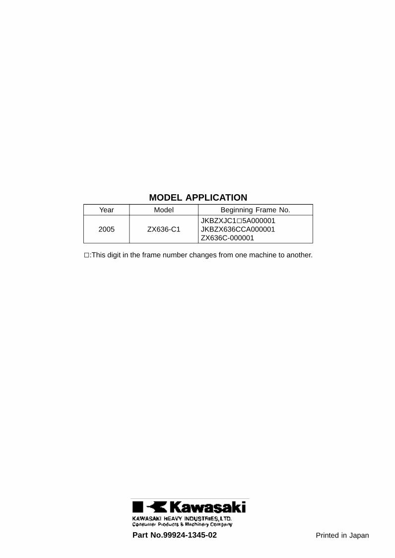
MODEL APPLICATIONYear Model Beginning Frame No.
2005 ZX636-C1JKBZXJC15A000001JKBZX636CCA000001ZX636C-000001
:This digit in the frame number changes from one machine to another.
Part No.99924-1345-02 Printed in Japan