motor truck scale - fairbanks scales home page · pdf file · 2017-11-18motor truck...
TRANSCRIPT

Instruction Manual
TITANMotor Truck Scale
Model: 6020 Series
FAIRBANKSS C A L E S
50745
Revision 5 03/10
© 2004-2010 by Fairbanks Scales Inc.
All rights reserved

Amendment Record
Titan 6020 Series
Motor Truck Scale
50745
Manufactured by Fairbanks Scales Inc.
821 Locust
Kansas City, Missouri 64106
Issue #1 01/04 New product
Issue #2 09/05 Revised cable routing drawings; formatting
Revision 3 06/07 Updated the Parts List
Revision 4 07/07 Updated drawings and Parts Lists
Revision 5 03/10 Updated Specifications and drawings
Disclaimer
Every effort has been made to provide complete and accurate information in this manual. However, although this manual
may include a specifically identified warranty notice for the product, Fairbanks Scales makes no representations or warranties
with respect to the contents of this manual, and reserves the right to make changes to this manual without notice when and
as improvements are made.
50745 2 03/10 Rev. 5

Table of Contents
Section 1: General Information . . . . . . . . . . . . . . . . . . . . . . . . . . . 4
Section 2: Description . . . . . . . . . . . . . . . . . . . . . . . . . . . . . . . . . . 5
Section 3: Installation
A. Preparations for Installations . . . . . . . . . . . . . . . . . . . 7
B. Foundation . . . . . . . . . . . . . . . . . . . . . . . . . . . . . . . . . 8
C. Setting the Modules . . . . . . . . . . . . . . . . . . . . . . . . . . 9
Section 4: Electrical Installation
A. Introduction . . . . . . . . . . . . . . . . . . . . . . . . . . . . . . . . 14
B. Description . . . . . . . . . . . . . . . . . . . . . . . . . . . . . . . . 14
C. Installation . . . . . . . . . . . . . . . . . . . . . . . . . . . . . . . . . 14
Section 5: Maintenance
A. Scale Maintenance . . . . . . . . . . . . . . . . . . . . . . . . . . 17
B. Mechanical Faults . . . . . . . . . . . . . . . . . . . . . . . . . . . 17
C. Replacing an RC Load Cell . . . . . . . . . . . . . . . . . . . . 17
Section 6: Parts List
A. Parts List . . . . . . . . . . . . . . . . . . . . . . . . . . . . . . . . . . 18
B. Load Cells and Load Cell Hardware . . . . . . . . . . . . . 18
C. O-Rings, Actual Size . . . . . . . . . . . . . . . . . . . . . . . . . 19
Section 7: Accessories
A. Field Installed Rub Rail Installation . . . . . . . . . . . . . . 20
APPENDIX I: Foundation Check List . . . . . . . . . . . . . . . . . . . . . . . . . 21
APPENDIX II: Wiring . . . . . . . . . . . . . . . . . . . . . . . . . . . . . . . . . . . . . 23
50745 3 03/10 Rev. 5

This Instruction manual provides installation instructions for the Fairbanks Titan Modular
Steel Deck Truck Scales.
For assurance of correct Titan scale installation(s), use:
• Methods and Procedures FF-2267 / 101732 (See Appendix.)
• The Certified prints/setting plans supplied with the scale
• This Instruction Manual, 50745
The concrete foundation work must be performed according to the certified prints issued for
the specific customer and order number. The name and order number for the particular
customer will be on the certified prints.
Section 1: General Information
50745 4 03/10 Rev. 5

The Titan Modular Steel Deck truck scales are available in various lengths from 27 to 105
feet, and widths from 10 to 14 feet. The scale is made up of modules of 27, 30, and 35 feet
in length. All modules are assembled and welded at the factory.
• The scale should be located so that vehicles can approach and exit the scale as
easily as possible.
• The platform should be visible from the instrument location.
• Drainage of surface water must be such that water does not collect under the scale.
• Smooth and level approaches are required at each end of the platform to reduce
loading shock and facilitate testing of the scale.
• Approaches must conform to the requirements of the law in the state in which the
scale is being installed. In the absence of such laws, the approaches must conform
to paragraph UR.2.6 National Institute of Standards and Technology Handbook 44,
which states that the first 10 feet must be level and on the same plane as the scale
platform.
NTEP CC: 96-089
CMA: AM-4949
50745 5 03/10 Rev. 5
Section 2: Description

50745 6 03/10 Rev. 5
Titan Steel Deck Truck Scale 6020 Series 100K CLC
L W CLC CapModel Scale Weight feet feet Klbs tons Sec
PLT-6020-T04 89801 12800 27 10 100 75 2
PLT-6020-T05 89802 14200 30 10 100 75 2
PLT-6020-T06 89803 16500 35 10 100 75 2
PLT-6020-T08 89804 28400 60 10 100 125 3
PLT-6020-T09 89805 33000 70 10 100 125 3
PLT-6020-T10 89806 38400 80 10 100 150 4
PLT-6020-T11 89807 42600 90 10 100 150 4
PLT-6020-T12 89808 49500 105 10 100 150 4
PLT-6020-U04 89809 14100 27 11 100 75 2
PLT-6020-U05 89810 15600 30 11 100 75 2
PLT-6020-U06 89811 18200 35 11 100 75 2
PLT-6020-U08 89812 31200 60 11 100 125 3
PLT-6020-U09 89813 36400 70 11 100 125 3
PLT-6020-U10 89814 42300 80 11 100 150 4
PLT-6020-U11 89815 46800 90 11 100 150 4
PLT-6020-U12 89816 54600 105 11 100 150 4
PLT-6020-V04 89817 15400 27 12 100 75 2
PLT-6020-V05 89818 17100 30 12 100 75 2
PLT-6020-V06 89819 19800 35 12 100 75 2
PLT-6020-V08 89820 34200 60 12 100 125 3
PLT-6020-V09 89821 39600 70 12 100 125 3
PLT-6020-V10 89822 46200 80 12 100 150 4
PLT-6020-V11 89823 51300 90 12 100 150 4
PLT-6020-V12 89824 59400 105 12 100 150 4
PLT-6020-W04 89825 18000 27 14 100 75 2
PLT-6020-W05 89826 19900 30 14 100 75 2
PLT-6020-W06 89827 23100 35 14 100 75 2
PLT-6020-W08 89828 39800 60 14 100 125 3
PLT-6020-W09 89829 46200 70 14 100 125 3
PLT-6020-W10 89830 54000 80 14 100 150 4
PLT-6020-W11 89831 59700 90 14 100 150 4
PLT-6020-W12 89832 69300 105 14 100 150 4

Installation consists of the following:
• Foundation check, layout, and base plate setting
• Tools, materials, documentation, and a crane
• Setting the modules
• Setting the modules on load cells
A. Preparations for Installation: Tools, Equipment, and Materials Required
1. Certified Prints
2. A mobile crane of sufficient capacity to safely lift and place the weighbridge
modules.
• Approximate Steel Deck Module maximum weight: 8 tons.
3. Four (4) equal length (20 ft) lifting chains or cables with hooks to safely attach to the
modules lifting channels located on the sides of the modules.
4. Machinist’s levels (Starrett # 134 & 132-6)
5. Hand tools
6. Hammer Drill with 5/8" bit, 16" long
7. Hydraulic jacks, 16 ton capacity
8. 100' steel tape measure
9. Stringline and chalkline
10. Prybars
11. High-quality grease and anti-seize
12. Load cell locating tools, Part No. 707118
50745 7 03/10 Rev. 5
Section 3: Installation
Note: The lifting straps MUST be requested in advance from the Crane Service Company.

B. Foundation:
Before installing any part of the scale, the foundation must be checked for accuracy
using Foundation Inspection, Field Check List, FF-2267 / 101732 (see Appendix ).
1. Layout and position the base plates in the proper locations using the Methods &
Procedures and certified prints. Each base plate must be level and in full contact
with the top of the pier. Adjustments can be made by chipping the concrete or
grouting under the base plates.
2. Re-check the locations of each base plate against the certified prints. Insert two ½"
roll pins into each base plate for anti-rotation. Position the plates with pins towards
the outside. This will leave the load cell cable exiting the load cell to the inside. It is
not necessary to install base plate anchors at this time.
3. Grease and install the inner O-ring in each load cell receiver cup. On all load cell
receiver cups, grease the large outer O-rings, then install one in the groove on the
outside of each cup. Put a 1/8" shim on the lower cups, grease the outside, then
insert the shim(s) into the base plates. Lower cups for the load cells have a pin
which must be aligned between the two roll pins in the base plate.
4. Place the upper cup with greased O-ring on the edge of the the upper foundation
next to each base plate.
5. Place the load cell locating tool next to each base plate.
50745 8 03/10 Rev. 5
UPPER L.C. RECEIVER CUUPPER L.C. RECEIVER CUPP
PPAARTRT #87482 #87482
PPAARTRT 87481 87481
LOWER L.C. LOWER L.C.
RECEIVER CURECEIVER CUPP
FOR INITIAFOR INITIALL iNS iNSTTALLALLAATIONTION
USE (1) 1/8" SHIMUSE (1) 1/8" SHIM
6" LOAD CE6" LOAD CELLLL
PPAARTRT #80453 #80453
"O"-RING ON EACH RECEIVER CU"O"-RING ON EACH RECEIVER CUPP
BASE BASE PPLLAATETE
LOAD CEL LOAD CELLL ASSEMBASSEMBLLYY DE DETTAIAILL
LOAD CELOAD CELLLL CABLE HANGER CABLE HANGER
(INSIDE (INSIDE FFACE OF SCALE)ACE OF SCALE)
PART #
PRE-TAPPED BAR �FOR JUNCTION BOX
CABLE HOLES
50745-1

C. Setting the Modules
1. Preparing The Modules For Lifting
• The module(s) are complete with channel pieces welded to the sides for
attaching lifting hooks. No lifting bolts are required.
2. Setting the Center or Base Module:
a. The center or base module is always set first. The center or base module will
have four (4) load cells to install; all other modules will have two (2) load cells.
The modules must be placed in the proper order and aligned in the foundation
so that all modules fit correctly.
b. These scales HAVE a definite orientation because of the junction box mounts
are welded to one (1) side only. The junction box mount side of the base
module should face the conduit of the main interface / homerun cable.
c. Place the safety blocks under the modules, which will set the modules at a
height slightly lower than the finished height.
d. Lift the center or base module to a location above the four load cell base plates.
50745 9 03/10 Rev. 5
50745-2

OPTION 1: Set the module directly on the locating tools and the blocks will act as safety stands.
• Install a load cell bearing cup with "O" rings into the upper receiver of each corneron the module. Grease will help hold the cup in place.
• Insert the upper end of the locating tool into the upper cup on the module.
• Lower the module while holding the locating tool upright and guiding the bottom ofthe tool into the lower cup.
• When the base module is set on all four locating tools, keep tension on the cablesuntil the module is centered and straight.
• Use hydraulic jacks to lift the unit slightly and shift the base plates to get the locatingtools plumb and the top and bottom flanges flush with the sides of the cup.
OPTION 2: Set the modules on the blocks first, then on to locating tools.
• The module is set on the blocks, keep tension on the cables until the module isproperly aligned.
• Use hydraulic jacks to lift the unit slightly, then install the locating tools. Shift thebase plates to get the tools plumb and the top and bottom flanges flush with thesides of the cup.
e. Measure from each side of each end of the module, to the end walls, to becertain the module is plumb and square before removing tension.
f. Once the tension on the lift cables is released, remove the lift brackets and/orhooks.
3. Setting End Modules
• Module Placement - Guide the modules into place with the supporting blocks onthe end of the module coming to rest on the supporting blocks of the centermodule. Lower the other end of the module onto the load cell locating tools orblocks.
50745 10 03/10 Rev. 5
50745-3

4. Before releasing cable tension
• Check the alignment of the end modules to the center or base module and tothe end wall.
• Using the provided shims, fill any gaps on the supporting blocks and get themodules properly aligned.
5. Connecting the Modules:
• Bolt the modules together using the 11/8" x 8" threaded rod, lock washers, flatwashers and nuts provided. Tighten the bolts snugly, but do not tighten themcompletely. Shim the supporting blocks, if necessary, to align the modules.
6. Checking Adjustment
a. Adjust End Checking
• Adjust the End Checking Bolts until they touch and prevent movement.
b. Install the side checking brackets:
• Bolt the brackets to the end checking plates embedded in the end walls per
certified prints. Adjust the bolts until they touch the channels they bump against.
50745 11 03/10 Rev. 5
PANEL CONNECTION DETAIL50745-4
* * Warning * *Module-to-module bolts MUST be installed correctly and torqued properly after all lifting iscompleted. Do Not substitute or omit bolts.
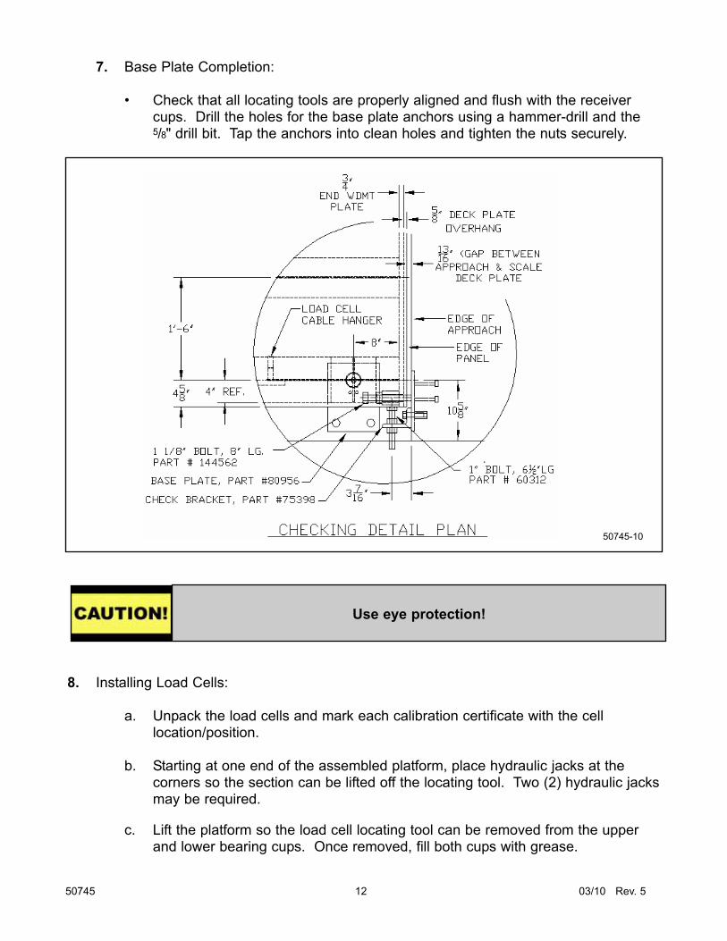
7. Base Plate Completion:
• Check that all locating tools are properly aligned and flush with the receivercups. Drill the holes for the base plate anchors using a hammer-drill and the5/8" drill bit. Tap the anchors into clean holes and tighten the nuts securely.
8. Installing Load Cells:
a. Unpack the load cells and mark each calibration certificate with the celllocation/position.
b. Starting at one end of the assembled platform, place hydraulic jacks at thecorners so the section can be lifted off the locating tool. Two (2) hydraulic jacksmay be required.
c. Lift the platform so the load cell locating tool can be removed from the upperand lower bearing cups. Once removed, fill both cups with grease.
50745 12 03/10 Rev. 5
Use eye protection!
50745-10

d. On the bottom of the load cells there are two flatsides which must be alignedwith the flats in the lower cup. Carefully lower the scale while seating thebottom of the cell into the lower cup. Check the scale's level and height,particularly at the approaches. Use the load cell shims provided to adjust loadcell cups for correct height and to ensure that all cells share the proper amountof load. Center section cells will have up to twice the deadload of end sectioncells.
e. When the modules are level and at the correct height, tighten the module-to-module bolts.
• The bolts should be torqued to 500 ft lbs.
f. Load cell cables:
• Route the load cell cables to the conduits that go through the scale andalso over the top of the module diaphram plates. Coil excess cables on thecable hanger on the interior side of the I-beams (see Image 50745-11).
9. Final Checking Adjustment:
a. Adjust End Checking
• Adjust the End Checking Bolts to allow 1/16” to 1/8” clearance.
b. Adjust side checking bolts to allow 1/16” clearance from block.
50745 13 03/10 Rev. 5
SIDE CHECKBRACKET
CHECKING DETAIL ELEVATION
3/4-10 X 3" FULL THDBOLTS, PART # 54559,(6) REQ'D EACHEND WALL
BASE PLATE
4' 7-3/8”10-5/8"
3-1/8"REF
1'-9”
CABLE HANGER
CABLE HOLE
5’-6”
LOAD CELL
50745-11

A. Introduction
The Titan scale was designed to be used with Intalogix™ systems. Intalogix™ systems
utilize smart sectional controllers (SSC) and pit power supplies (PPS) for load cell
excitation and signal processing.
Analog instruments cannot be used with this platform. The sensitivity using a analog
indicator would be approximately a half (.5) microvolt. Most analog instruments have a
minimum sensitivity of one (1) microvolt.
B. Description
There is one (1) SSC per section and one (1) PPS for the entire platform unless the
number and resistance of the cells require a second pit power supply. Smart sectional
controller boxes have four (4) terminals: two (2) for load cells and two (2) for interfacing
to other SSC boxes or terminating to a pit power supply. All cell/section/scale
adjustments are made via the Intalogix™ system instrument.
C. Installation
a. Boxes
The box has mounting brackets which allow mounting to the side of the Titan
modules.
b. Wiring
Cable used in all wiring must be a minimum of 18 AWG. Use cable 17204 or 17246.
Use appropriate service manual for the indicator being installed or refer to the
Appendix for typical wiring information.
50745 14 03/10 Rev. 5
Section 4: Electrical Installation
50745-650745-6

c. Smart Sectional Controller
Wire cells into each section’s sectional controller per the appropriate service manual.
Refer to the Appendix for typical wiring information.
Load Cell Wiring Designations
Color Description
Black (-) Excitation
Green (+) Excitation
Red (-) Signal
White (+) Signal
Yellow Shield
50745 15 03/10 Rev. 5
Note: The Titan has been designed to provide protection from the effects of moisture. The load cells have been calibrated with the cable attached, and therefore the cableshould NOT be cut. The cable is connected directly to the sectional controllerthrough a sealed gland fitting which MUST be tightened properly to keep water andmoisture out of the box. All cabling should have a drip loop at the cell or box entrylocation to help prevent water entry. On all boxes, the load cell cable gland fittingshave O- rings that can be forced out of position if tightened improperly. To preventthis, first tighten the inner nut securing the gland in the hole, then insert the cableand carefully tighten the gland. Do not over-tighten where the gland turns . The cover MUST be secured with ALL screws tightened properly (10 in/lbs) forprotection against moisture.
Note: Smart Sectional Controllers have connections for two (2) load cells, TB1 and TB2.
The odd numbered cell connects to TB1 and the even numbered cell connects to TB2.
1 3 5 7
2 4 6 8
IndicatorScale house
50693-150746-12

d. Grounding - Smart Sectional Controllers
Intalogix™ systems must have two (2) ground rods in the foundation for proper
connection. Pit power supplies use a ground separate from the weighbridge ground
rod.
e. Indicator to Pit Power Supply Cable Connection
Prepare the cable ends in the standard manner. Use the appropriate manual for
wiring instructions for the sectional controllers and power supplies. Connect the
indicator interface cable to the instrument in the scale house per the instructions in
the appropriate indicator service manual.
50745 16 03/10 Rev. 5
Note: Intalogix™ installations utilize a specific numbering system for load cells because of
digital addressing of the SSCs.
Number the load cells as follows: With respect to the following starting position,
face the platform from where the indicator is located. The cell at the upper left or far
side of the platform is Cell 1. The cell positions along the far side will be odd cell
numbers, the near side locations will be even cell numbers (see Image 50745-12).
Improper grounding will prevent the surge voltage protection fromadequately protecting the scale.

50745 17 03/10 Rev. 5
A. Scale Maintenance
1. Check for accumulations of solid material under the scale which may affect theaccuracy, i.e., ice, frozen mud, debris.
2. Have the customer clean under the platform regularly.
3. Inspect load cells for damage to the ends/cables, check cups and O-rings fordamage.
4. The load cell bearing cups should be inspected, cleaned and greased periodically.
5. Inspect and adjust all checking to proper tolerances.
B. Mechanical Faults
1. Check all clearances around the scale for any obstructions or interference with themovement of the platform.
2. Check all check bolt clearances, both with and without a concentrated load overeach section, individually.
3. Check all load cells for plumb and level.
4. Inspect the boxes for leaks; the interior should be clean and dry. If there is moistureinside, clean, then dry it out thoroughly. Check all connections at the terminalblocks.
C. Replacing a load cell
1. Remove power from the instrument.
2. Lift the scale using a proper sized and rated hydraulic jack(s) at the corner(s) closeto the defective cell location.
3. Check upper and lower receiving cups, and O-rings for damage. Replace asnecessary and reapply grease.
4. Insert the new cell into the upper receiving cup & position the anti-rotation pin.
5. Carefully lower the hydraulic jack(s) until the cell is set into the lower cup.
6. Remove the cover of the sectional controller, then loosen the gland bushing to freethe cable. Remove the old cell wires and connect new cell wires in the sectionalcontroller. Latch the cover. Tighten all gland nuts with a wrench to secure.
7. Test and adjust scale as necessary.
Section 5: Maintenance

A. Parts List
Part No. Description
75458 11/8" - x 41/2" w/ nut (module - module)
54788 11/8" lock washer (module - module)
54255 11/8" flat washer (module - module)
80956 Load Cell Base Plate
61743 Clamp Bar Washer (base plates)
62857 5/8" x 6" Anchor Bolts
55010 Ground Rod Kit
144562 Check Bolt 1 1/8” x 8”
75398 Check Bracket
60312 Side Check Bolt 1” x 6 1/2”
B. Load Cells and Load Cell Hardware
Part No. Description
80453 Load Cell, 6" RC, 100K, 1000 ohm, 2mv/v
73682 Shim, receiver cup, 1/16"
64338 Shim, receiver cup, 1/8"
64334 Shim, receiver cup, 3/16"
72274 "O" Ring, INSIDE of Cup, ANSI #222
64340 "O" Ring, OUTSIDE of Cup ANSI #228
87481 Receiver Cup, LOWER (w/ anti-rotation pin)*
87482 Receiver Cup, UPPER**
64382 Roll Pin, ½" x 2½" anti-rotation, baseplate
63981 Anti-Rotation Pin, LOWER Receiver Cup 3/8" x 2½"
107118 Locating Tool 6"
* If manufactured before 07/01/07, then order part no. 70511.
** If manufactured before 07/01/07, then order part no. 70512.
50745 18 03/10 Rev. 5
Section 6: Parts List

C. O-Rings, Actual Size
50745 19 03/10 Rev. 5
Part No. 64340
ANSI # 228
Outside of all
load cell cups
2 1/4" I.D.
2 1/2" O.D.
1/8" Thickness
Part No. 72274
ANSI # 222
Inside of cup
1 1/2" I.D.
1 3/4" O.D.
1/8" Thickness
50745-7

A. Field Installed Rub Rail Installation
• Disconnect all loadcells. Electrically isolate the load cells from the platform.
• Use the print with the accessory for actual measurements
• Clean (remove primer) the areas to be welded for good penetration.
• Weld stiffeners to the side weldments.
• Bolt the gussets to the stiffeners and end weldments.
• Weld pipe to the gussets.
• Clean and paint (paint provided) all weld areas.
50745 20 03/10 Rev. 5
Section 7: Accessories
* * Warning * *
Fairbanks does NOT recommend using foundation- or ground-installed guide rails along
the sides of a truck scale platform. Damage may occur to the scale if a truck hits the
guide rail, transferring damaging forces to the platform and the checking system.
Use of this style guide rail will void product warranty.
PIPE
1/4"TYP.
GUSSET
1/2"UP WELD WELD
TYP. VERTICAL
NO WELD2 3/8"
NO WELD
2 3/8"
STIFFENERS
GUSSET 3" DIA. PIPE
50745-2

50745 21 03/10 Rev. 5
Foundation InspectionFOUNDATION FIELD CHECK LIST
(Field Form)
A Foundation Inspection should ALWAYS be performed prior to scale installation and to confirm correct foundation
construction. If possible this should be done prior to scale shipment.
Tools required: Certified drawings and site plan 2' to 4' level
100' and 25' steel tapes Hammer and concrete nails
Laser or builders level if possible String line (construction string)
Straight edge for pit foundations (2 x 4, very straight and 4" wider than pit walls
Construction paint (up-side-down type, for marking concrete).
Perform the following Foundation Checks. Refer to Methods and Procedures for complete description of each
step. Recommended to copy check list and keep in job file. ALWAYS familiarize yourself with the CERTIFIED
foundation prints for the job you are working on as model numbers and specifications are subject to change.
1. Site Plan and Certified Prints should be thoroughly reviewed to confirm accurate locations to the scale and
all extra items (scoreboards, lights, poles, etc.) that are included in the bid or contract.
2. Check for truck and crane access, overhead wires, fences, green concrete, etc.
3. Dimensional length and width check; check all 4 sides and record on chart (other side).
4. Diagonal measurements check to verify that the foundation is square and record on chart (other side).These
measurements should be equal, or within 1/2". Greater error could result in the scale not fitting in the foundation.
5. Check ALL pier heights to make sure they are the proper elevation and record on chart (other side). To high
and the scale will not fit correctly, to low could result in excessive shimming..
6. In pit foundations check walls to verify they are straight. Straight walls are very important, but are even
more critical for modular scales like the Rodan series.
7. Verify conduit locations and pull strings (if needed).
8. Verify ground rod locations.
9. Verify that drains and sump openings are piped correctly and are clear of debris.
10.Check the end coping to ensure they are centerline and that the coping is correct for the scale being
installed (10',11' or 12' width, etc). Check all coping, side and end, for hollow areas.
11. Verify location of any and all required embeds or pre-installed baseplates (i.e., Hwy System, RR scales, etc).
All of these dimensions will be located on the Certified foundation prints.
12.Layout - To help in locating pre-installed baseplates, embeds, load-cell centerlines, etc., refer to
Methods and Procedures section on Layout. See other side for foundation & Layout charts.
FF-2267 Issue #1
Appendix I: Foundation Check List
Titan Series.

50745 22 03/10 Rev. 5
3 _____________
4 _____________
1 _____________ 2 _____________
CL
concretenails
B
C
C
B
A
B = 1/2 of the coping length OR Centerline
Load Cell Data Line
CL = Centerline of of Scale= Concrete Nails
C = Distance from Centerline to Load Cell Data Lines
A = Coping Length
Measurement "A" to "A" _________________
Measurement "B" to "B" _________________
B
B
A
A
B
B
A
C D E
X X
X X
Load Cell Data Line
TOP VIEW
1 _____________ 3 _____________ 5 _____________ 7 ____________ 9 ____________
2 _____________ 4 _____________ 6 ______________ 8 ____________ 10 ___________
Pier Pier
Side View
Strings
Length & Width Check
Diagonal Measurements Check
Pier Height Check
Longitudinal Layout
Lateral Layout
FF-2267 Issue #1

50745 23 03/10 Rev. 5
Appendix II: Wiring
1 2 3 4 5 6 7 8T
B1
1 2 3 4 5 6 7 8T
B1
1 2 3 4 5 6 7 8T
B1
1 2 3 4 5 6 7 8T
B4
1 2 3 4 5 6 7 8T
B3
1 2 3 4 5 6 7 8T
B2
1 2 3 4 5 6 7 8T
B2
1 2 3 4 5 6 7 8T
B3
1 2 3 4 5 6 7 8T
B4
Indi
cato
rS
SC
1S
SC
2P
PS
S A M E-
Exc
itatio
n-
Exc
itatio
n
+ E
xcita
tion
+ E
xcita
tion
+ O
utpu
t+
Out
put
- O
utpu
t-
Out
put
1 2 3 4 5 6 7 8T
B1
1 2 3 4 5 6 7 8T
B2
1 2 3 4 5 6 7 8T
B3
1 2 3 4 5 6 7 8T
B4
- E
xcita
tion
- E
xcita
tion
+ E
xcita
tion
+ E
xcita
tion
+ O
utpu
t+
Out
put
- O
utpu
t-
Out
put
5059
7-2
-8.0
Vol
ts+
8.0
Vol
ts
DC
Ret
urn
Shi
eld
RS
-485
+R
S-4
85-
-
* N
ot U
sed
Load
Cel
l 1Lo
ad C
ell 4
*
AC
R
DC
EN Shi
eld
TX
RX
AC
( 28V
)
( 20V
)
( DC
R)
Load
Cel
l 2Lo
ad C
ell 3
( 17
246
Cab
le )
Bla
ckG
reen
Blu
eS
hiel
d
Red
Whi
te
Shi
eld
Shi
eld
Shi
eld
Shi
eld