motor terminology and electrical performance characteristics
TRANSCRIPT

Motor Terminology and Electrical Performance
Characteristics
Motor Terminology and Electrical Performance Characteristics • Overview/Objectives:
o Power supply terms
o Speed / #Poles
o Horsepower
o Current
o Speed vs. Torque
o Service Factor

AC Power Supply Terms
• Phase: describes the type of AC power supplied (Single or Three). Does not apply to DC.
• Frequency or Hertz (Hz): How many times a second the AC changes directions from positive to negative.
• Voltage: Defines the strength of the electric power

Powe
r
Phase Cycl
e
Voltages
AC Single 60 115 or 230
AC Single 50 110, 208, 220 or 240
AC Three 60 208, 230, 460, 575, 2300,
4160, 6600, or 13.8 kV
AC Three 50 190, 380, 400, 415, 690,
4000 or 11 kV
Typical Power Supply
Motor Performance Characteristics • Speed / #Poles
• Horsepower
• Current
• Speed vs. Torque
• Service Factor

Motor Operating Speeds • Mechanical speed tied to speed of rotating
magnetic field in stator
o Synchronous Speed = 120 x Frequency
# Poles
o Rotor lags behind - difference called “Slip”
o Speeds at 60 Hz. - Full Load Speed is approximate
# Poles Sync. Speed Nominal FL Speed
2 3600 RPM 3550 RPM
4 1800 RPM 1750 RPM
6 1200 RPM 1150 RPM

Synchronous
Speed (RPM)
# of
Poles
Frequency
(Hz)
Formula
3600 2 60 S = (120x60) / 2
1800 4 60 S = (120x60) / 4
1200 6 60 S = (120x60) / 6
900 8 60 S = (120x60) / 8
720 10 60 S = (120x60) / 10
3000 2 50 S = (120x50) / 2
1500 4 50 S = (120x50) / 4
1000 6 50 S = (120x50) / 6
750 8 50 S = (120x50) / 8
600 10 50 S = (120x50) / 10

What is Slip? • Ratio between:
Full Load Speed and No Load Speed
% 𝑺𝒍𝒊𝒑 = 𝟏 − 𝑭𝒖𝒍𝒍 𝑳𝒐𝒂𝒅 𝑹𝑷𝑴
𝑵𝒐 𝑳𝒐𝒂𝒅 𝑹𝑷𝑴× 𝟏𝟎𝟎
% 𝑺𝒍𝒊𝒑 = 𝟏 − 𝟏𝟕𝟓𝟎
𝟏𝟖𝟎𝟎× 𝟏𝟎𝟎 = 𝟐. 𝟕𝟖%

Horsepower and Torque
Torque/Hp Speed @ 60Hz
(lb/ft) Synchronous
2 1.5 3600
4 3 1800
6 4.5 1200
8 6 900
10 7.5 720
12 9 600
Poles
𝑯𝑷 = 𝑺𝒑𝒆𝒆𝒅 × 𝑻𝒐𝒓𝒒𝒖𝒆
𝟓𝟐𝟓𝟐
𝑻𝒐𝒓𝒒𝒖𝒆 = 𝑯𝑷 × 𝟓𝟐𝟓𝟐
𝑺𝒑𝒆𝒆𝒅

Rules of Thumb
Motor Amps per HP - (full load)
460v, a 3-phase motor draws 1.25 amps per HP
230v, a 3-phase motor draws 2.5 amps per HP

Effects of Voltage Variations on AC Motors
Low Voltage
1. Reduced starting torque - Motor may not be able to start load.
2. Reduced running torque - Current increases to produce 100% torque creating excessive heat. Increased heat causes premature insulation failure.
3. Speed decreases / Process interruption
High Voltage
1. Increased starting current - Nuisance trip of overloads. Increased heat can cause insulation damage.
2. Increased starting and running torque.
3. Speed increases / Process interruption
• NEMA allows A+/- 10% voltage variation with no frequency variation.

Is it true?
• A motor, depending on its design can produce torque indefinitely without producing horsepower
• A motor cannot develop horsepower without first producing torque
• A motor needs to rotate to develop horsepower in order to do work

Motor Speed Torque Curve
Motor Designs
• The Material and Shape of the Rotor Bars Are the Main Factors in Obtaining Various Speed/Torque Curves
• NEMA Defines 4 Basic Types of Speed/Torque Characteristics for Induction Motors:
o DESIGN A
o DESIGN B
o DESIGN C
o DESIGN D
• The Stator Has Little to Do With the Shape of the Motors Speed/Torque Curve
• Different Rotors Could Be Used With the Same Stator to Change the Characteristic Shape

Typical Current & Torque Relationship for Squirrel Cage Induction Motor
Nema
Des.
Starting
Torque
LR amps BD torq FL slip Applications
A Normal High High Low Mach. Tools,
fans
B Normal Normal Normal Normal General
Industrial
C High Normal Normal Normal Conveyor
D Very
High
Low n/a High Hoists 0
% Current
% Torque
% Speed
Current
200
400
600
25 50 75 100
Torque

ROTOR DESIGN Slot Shapes
• LRT Normal (90 – 100%)
• LRA High >650%
• BDT High >200%
• FL Slip Low
• Cross section of the bar is large (low resistance) and not too deep in the iron (low reactance).
Design A
ROTOR DESIGN Slot Shapes
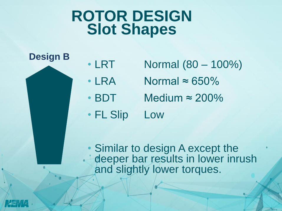
• LRT Normal (80 – 100%)
• LRA Normal ≈ 650%
• BDT Medium ≈ 200%
• FL Slip Low
• Similar to design A except the deeper bar results in lower inrush and slightly lower torques.
Design B

ROTOR DESIGN Slot Shapes
• LRT High > 150%
• LRA Normal ≈ 650%
• BDT Medium ≈ 200%
• FL Slip Low – Med < 5%
• Design C utilizes a double cage slot. The high resistance of the upper cage delivers high starting torque.
Design C

ROTOR DESIGN Slot Shapes
• LRT Very High > 200%
• LRA Normal ≈ 650%
• BDT High > 200%
• FL Slip High (5 – 8%, 8 – 13%)
• Bar shape and brass or similar alloy is used for high resistance (high starting torque) and high slip.
Design D

Motor Starting - Inrush Currents
• Locked Rotor Current typically 600 -700% of full load
• Current and torque aren’t proportional until near full load

What is Large AC? Per NEMA, Large Induction Machines include ratings greater than:
Sync. RPM Motors-HP Generators-kW
3600 500 400
1800 500 400
1200 350 300
900 250 200
720 200 150
600 150 125
514 125 100
450 ALL ALL
NEMA MG 1 Part 20
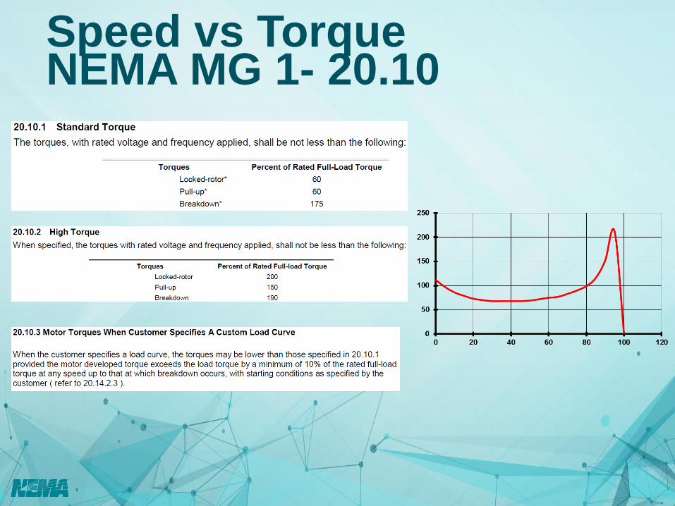
Speed vs Torque NEMA MG 1- 20.10

Speed vs Torque - Application Constant Torque
– Reciprocating
Compressor
– Reciprocating Pump
– Extruder
– Conveyer
Variable Torque
– Centrifugal Pump
– Centrifugal
Compressor
– Fan

Application Characteristics • Required HP, Speed, and Voltage
• Application (Type of Load)
• Starting / Running Method

Motor Starts
• Every time a motor starts its components are subjected to mechanical and thermal stress.
o Rotors
o Winding insulation
• Number of starts per time should not be exceeded.
o 2 starts loaded with motor at ambient temperature
o 1 start loaded with motor at operating temperature
o Followed by required cooling time

Consider the applied load inertia at the motor shaft……

LOAD CURVES Pump/Fan
0
20
40
60
80
100
0 20 40 60 80 100 120
% T
orq
ue
% Speed
Open Valve (Pump)Open Damper (Fan)
Closed Valve (Pump)Closed Damper (Fan)
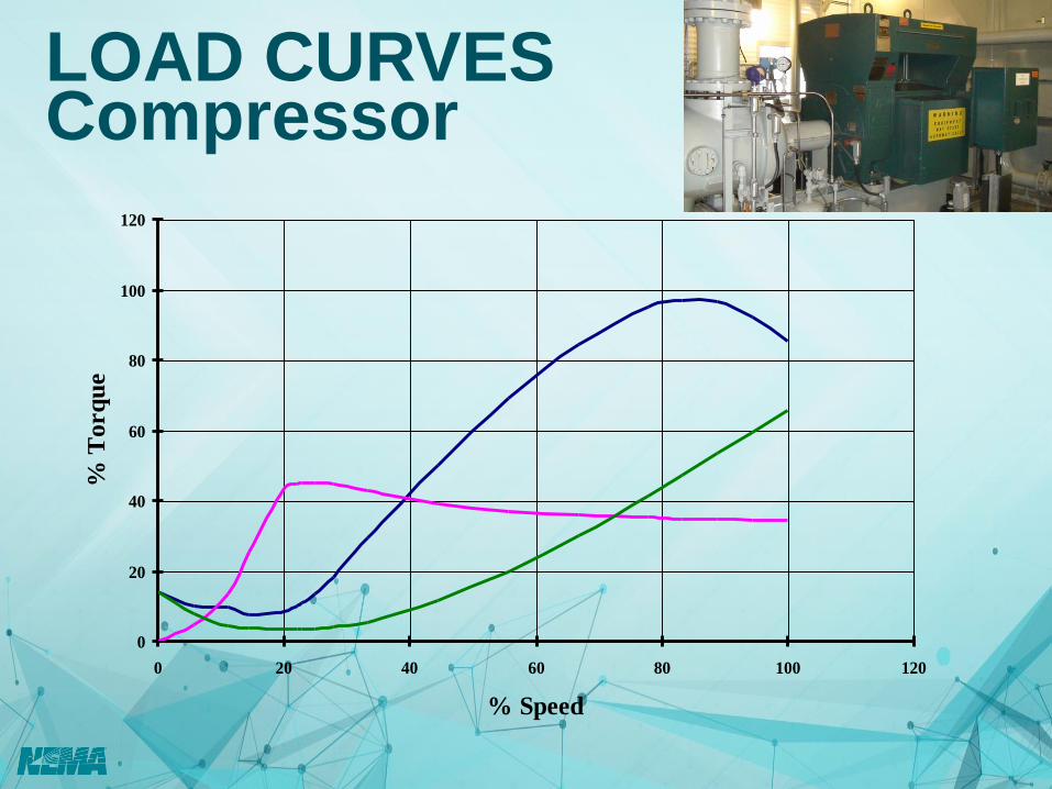
LOAD CURVES Compressor
0
20
40
60
80
100
120
0 20 40 60 80 100 120
% Speed
% T
orq
ue
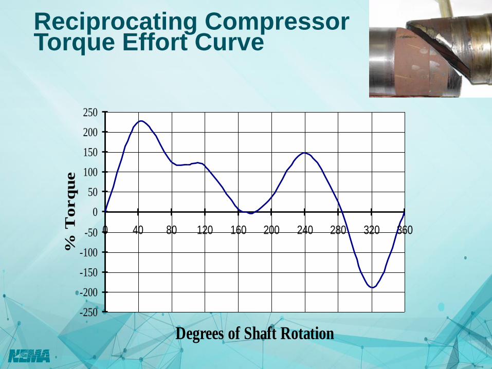
Reciprocating Compressor Torque Effort Curve
-250
-200
-150
-100
-50
0
50
100
150
200
250
0 40 80 120 160 200 240 280 320 360
Degrees of Shaft Rotation
% T
orq
ue

Speed
LOAD CURVES Conveyor
Torq
ue

Starting Method
• Full Voltage
• Auto Transformer / Voltage Dip
• Current Limiting Soft Start
• Adjustable Speed Drive
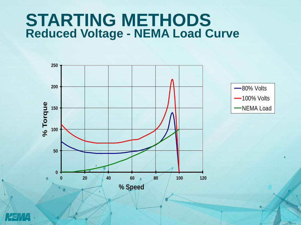
STARTING METHODS Reduced Voltage - NEMA Load Curve
0
50
100
150
200
250
0 20 40 60 80 100 120
% T
orq
ue
% Speed
80% Volts
100% Volts
NEMA Load

STARTING METHODS Reduced Voltage - 50% NEMA Load Curve
0
50
100
150
200
250
0 20 40 60 80 100 120
% T
orq
ue
% Speed
80% Volts
100% Volts
50% NEMA Load

STARTING METHODS Current Limiting Soft-Start (250% FLA)
0
100
200
300
400
500
600
700
0
50
100
150
200
250
300
0 20 40 60 80 100 120
% T
OR
QU
E
% SPEED
100% TORQUE
LIMITED TORQUE
LOAD TORQUE
100% CURRENT
LIMITED CURRENT

VFD Starting

AC Motor Torque on Variable Frequency
Rated
50% Overload
Quiz
• Single phase 575V motors are a common design, True or False?
• The lag between the rotor and the moving magnetic fields in the motor is referred to as?
• Speaking relative to inrush on starting; locked rotor current is typically XXX% of full load
• Name two motor starting methods
37
•False: 575V relates to 3 phase power
•“Slip”
•600-700%
•Full Voltage, Auto Transformer/Voltage
Dip, Current limiting, Adjustable speed
drive