motor starting studies - add …docshare01.docshare.tips/files/23334/233345161.pdfalso, in drive...
TRANSCRIPT
6MOTOR STARTING STUDIES
6.1 INTRODUCTION
A large number of induction motors are used in industrial facilities to performvarious drive applications. Starting large induction motors on line can causesevere disturbance to the motor, to the load and to the other power system loadsconnected close to the motor. All the polyphase induction motors can beclassified into squirrel cage and wound rotor type. The wound rotor inductionmotors are suitable for loads requiring high starting torque with reduced startingcurrents. The squirrel cage induction motors are robust and require very littlemaintenance during normal operating conditions. Therefore, many of theindustrial drives are equipped with squirrel cage induction motors. The squirrelcage induction motors are classified by the National Manufacturers Association(NEMA) based on the torque speed characteristics as design A, B, C or D.Recently, the high efficiency motors are being classified as Design E motors.The speed torque characteristics of all the four designs are presented in Figure6.1. Some of the approaches in the application of these motors are presentedbelow.
Design A motors usually have low rotor resistance, single cage type withexcellent running characteristics. The starting current is high with moderatestarting torque. Typical loads are fans, blowers and pumps.
Copyright 2002 by Marcel Dekker. All Rights Reserved.

• • • • Design B
- - —Design A
Design C
Design D
0.2 0.4 0.6
Speed, P.U.
0.8
Figure 6.1 Torque Speed Characteristics of Design A, B, C and D Motors
Design B motors are of the double cage type with high rotor resistance and are usedfor full voltage starting. These motors have about the same starting torque as designA, but somewhat lower performance at the operating point, and the sameapplications as design A. This is the most commonly used squirrel cage motor.
Design C motors are also double cage design with higher rotor resistance thandesign B, with better starting torque, drawing relatively low starting current. Theapplications are constant speed loads such as conveyors and crushers.
Design D motors have higher starting torque than all the squirrel cage motors usinga high rotor resistance. They have low efficiency and are used for high inertia loadssuch as die-stamping machines, punch presses and shears.
Design E motors are energy efficient and are not available widely. These motorsare intended to provide better efficiency than Design B motors. A 200-hp design Emotor has an efficiency of 95.8% as opposed to 95% efficiency for a standardmotor. The difference is greater for smaller motors. Also, the locked rotor currentof Design E motors are much higher than standard designs. Such a design will resultin a larger voltage drop during motor starting.
The online starting of any of these motors draws significant starting currentproducing voltage drop. Therefore, some of the motors are provided with startersand online starting requires careful consideration.
Full voltage starting is most commonly used because of its simplicity and low cost.In this case the motor is connected to the power system through a circuit breaker.With this method, the inrush current drawn from the line, the sudden application of
Copyright 2002 by Marcel Dekker. All Rights Reserved.

torque to the load and the mechanical stresses produced on the motor windings willbe significant. However, most power systems can supply the inrush current withoutproducing appreciable voltage drop for starting small and medium size motors.Also, in drive applications, sudden load torque may not produce any mechanicaldamage in most cases. Maximum torque is available to the load, although thereduction in motor torque produced by the voltage drop at the motor terminals mustbe considered in specifying the torque required. Presently, the motor end windingsare braced and can withstand stresses produced by the inrush current when startedon full voltage.
A frequent problem has been failure to start when the motor coupled to its load isenergized for the first time. Typically the motor appears to start smoothly, then istripped off line by relay action before it reaches full speed. When the starting time isprolonged enough to exceed the permissible locked rotor time, the relay can operateeven though its time current curve is at all points above the motor starting curve.Some of the effects of starting a large motor are presented below.
Motor terminal voltage - During the starting, the motor terminal voltage shouldbe maintained at approximately 80% of the rated voltage for type B motors having astandard 150% starting torque at full voltage with a constant torque load applied. A81.6% rated voltage will develop a torque T = 0.8162 x 150% = 100%. Also, inevery case the starting time has to be evaluated for the 11 damage limit of the motor.
Effect of motor starting on other running motors - Motors that are runningnormally on the system will slow down in response to the voltage drop occurringwhen a large motor is started. The running machines must be able to reaccelerateonce the machine being started reaches the operating speed. If the voltage drop isvery severe, the loading on the running machines may exceed the breakdown torqueat the reduced voltage. The decelerating machines may impose heavy currentdemand to produce excessive voltage drop.
Heavy starting currents - In the case of design B motors, the pullout torque is200% of the rated torque. If the motor terminal voltage falls below 71% of therated voltage the motor may stall. This is based on the assumption that thedeveloped torque is proportional to V . If other than design B motors are used onthe system, a similar criterion can be established to evaluate re-accelerationfollowing a motor starting.
Flicker - Power system loads such as computer equipment, power electronicequipment and sensitive control devices may be affected during motor starting.There is a wide variation in the magnitude of the voltage drop by electronicequipment. Voltage fluctuations may also cause objectionable light flicker in
Copyright 2002 by Marcel Dekker. All Rights Reserved.
domestic applications. The flicker curves and the allowed flicker levels arediscussed in detail in Chapter 8. For various new electronic equipment, theallowable voltage drop data has to be obtained from the manufacturer.
Effect on control devices - The control devices are not required to pick up atvoltages below 5% of the rated name plate value. The dc control devices canoperate at 80% of the rated voltage. Critical control operations can thereforeencounter difficulty during the motor starting period if the voltage drop is excessive.The actual drop out voltage of industrial contactors is 60% - 70% of the ratedsystem voltage.
6.2 EVALUATION CRITERIA
The online switching device can be a molded case circuit breaker, or oil-immersedcircuit breaker, or air break circuit breaker, either held closed magnetically orlatched in. For a given rating, the oil-immersed circuit breaker has a lower initialcost but requires greater maintenance. For some applications the choice of thecircuit breaker is determined by the interrupting rating of the system.
According to the IEEE Standard 399 a motor starting study should be performed ifthe motor horse-power exceeds approximately 30% of the supply transformer basekVA rating if no generators are present. For smaller horse power motors, a study isneeded depending on the daily fluctuation of nominal voltage, size and length of thecable, load rating, regulation of the supply voltage, transformer impedance and tapratio, load torque and motor torque.
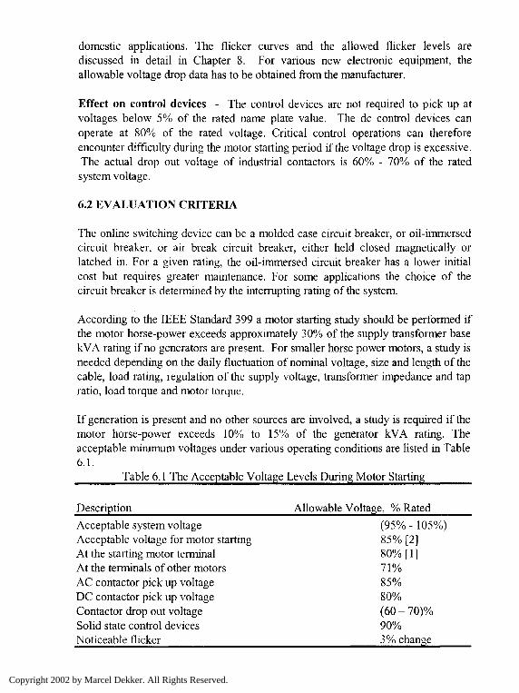
If generation is present and no other sources are involved, a study is required if themotor horse-power exceeds 10% to 15% of the generator kVA rating. Theacceptable minimum voltages under various operating conditions are listed in Table6.1.
Table 6.1 The Acceptable Voltage Levels During Motor Starting
Description Allowable Voltage, % Rated
Acceptable system voltage (95% - 105%)Acceptable voltage for motor starting 85% [2]At the starting motor terminal 80% [ 1 ]At the terminals of other motors 71 %AC contactor pick up voltage 85%DC contactor pick up voltage 80%Contactor drop out voltage (60 - 70)%Solid state control devices 90%Noticeable flicker 3% change
Copyright 2002 by Marcel Dekker. All Rights Reserved.

The above criteria can be used to evaluate the voltage drop due to motor starting ina power system.
6.3 STARTING METHODS
If a normal supply voltage is applied to an induction motor at standstill, the startingcurrent will be on the order of 6 times the rated current. The starting torque is alsolimited and can be improved by inserting a resistance in the rotor circuit in the caseof slip ring motors. However, there is need to limit the inrush current during thestarting. There are several starting methods used for large motors.
Series impedance starting - A resistance or reactance can be used in series withthe motor winding during starting. Then by using a contactor, the series impedancecan be short circuited. If a series reactance is used in the starting, the power factorwill be poor and produce significant disturbance in the line. If a series resistance isused, then the power factor will be better, but the losses in the resistance will behigh. Standard reactors are available to limit the starting voltages at the motorterminal to 50%, 75% and 90% of the terminal voltage at the instant of starting.When starting with a series reactance the kVA drawn from the supply is reduceddirectly proportional to the applied voltage and the motor torque is reducedproportional to the square of the voltage. If x is the fraction of the voltage reducedby the series impedance, then the starting current and the torque are given by:1st = x Isc (6.1)
Tst
Tst
Tf
2 „,= x Tsc
(1st}2 ,V I f J
f x l ^sc
Ifv y v y
2- X
^1scIf
V J
(6.2)
sf (6.3)
Using the above relations, the starting current and the starting torque can beevaluated if the full load current, short circuit current, slip at the rated load, the fullload torque and the fraction of the voltage applied are known.
Auto-transformer starting - In this method, a reduced voltage is applied to themotor using an auto-transformer and the voltage is increased to the nominal valueafter the starting. With auto-transformer starting, the acceleration time of the motoris longer, if a constant torque is produced during the starting. Further, the reactanceof the auto-transformer is in parallel with the motor. In the case of an auto-transformer starting, if a tapping of transformation x is used then the phase voltageacross the motor is (x VA/3). With the auto-transformer starter the equations (6.1)through (6.3) can be used.
Copyright 2002 by Marcel Dekker. All Rights Reserved.

Wye/delta starter - For small and medium size motors, the wye/delta starter can beused. The stator winding is connected in wye during the starting and in delta for therunning. This starter is the simplest form of mechanical equipment and is suitable
for small and medium size motors.
Shunt capacitors to reduce the starting current - The shunt capacitors can beused across the motor terminals to reduce the reactive component of the currentduring the starting. Experimental results on a 2-hp, 220 V, 7 A, 3,600 rpm, wyeconnected, three-phase induction motor show significant reduction in the linecurrents. The starting currents without and with shunt capacitors are listed in Table6.2.
Table 6.2 Starting Currents Without and With Shunt Capacitors
Case Description Current, AMotor without shunt capacitors 50.0 AMotor with 240 MFD shunt capacitors 34.5 AMotor with 480 MFD shunt capacitors 31.0 A
The shunt capacitors can cause ferroresonance when interacting with the magneticcircuit of the induction motors. Therefore, the shunt capacitors has to be switchedoff as soon as the starting is completed. However, switching off the shunt capacitorsrequires further consideration from the transient recovery voltage point of view.
Example 6.1 - Find the percentage of tapping required on an auto-transformer tostart an induction motor against 1/3 of the full load torque. The short circuit currentwith a normal voltage is 6 times the full load current and the full load slip is 3%.
Tst 1 JstSolution- — = ~ — = 6 sf =0.03
Tf 3 If
f
( ^2Tst 2 I Isc
= X
TfSj
1 2 2- = x (6) (0.03)3Solving for x, the required transformer tapping, x = 0.56 or 56%
Example 6.2 - A three-phase, 6-pole, 60 Hz induction motor takes 60 A at the fullload and runs at 1160 rpm to develop the rated torque. The starting current at ratedvoltage is 300 A. Calculate the starting torque for online and wye/delta starting.
Copyright 2002 by Marcel Dekker. All Rights Reserved.
Solution- Isc = 300A, If =60 A
Xf
stTf
Isc
fSf for online starting
v i /1200 -1160 \
- 0.0331 ^ 1200 )
T f \^
-§L = -?_ 0.033 = 0.825T,- V 60 J^ v y
If a wye/delta starter is used,
sf = I - II ̂ ^ I 0.033 = 0.275
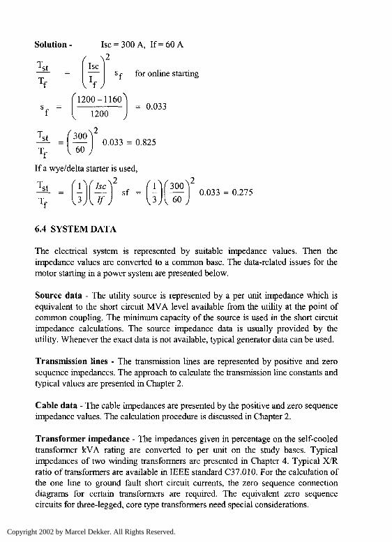
6.4 SYSTEM DATA
The electrical system is represented by suitable impedance values. Then theimpedance values are converted to a common base. The data-related issues for themotor starting in a power system are presented below.
Source data - The utility source is represented by a per unit impedance which isequivalent to the short circuit MVA level available from the utility at the point ofcommon coupling. The minimum capacity of the source is used in the short circuitimpedance calculations. The source impedance data is usually provided by theutility. Whenever the exact data is not available, typical generator data can be used.
Transmission lines - The transmission lines are represented by positive and zerosequence impedances. The approach to calculate the transmission line constants andtypical values are presented in Chapter 2.
Cable data - The cable impedances are presented by the positive and zero sequenceimpedance values. The calculation procedure is discussed in Chapter 2.
Transformer impedance - The impedances given in percentage on the self-cooledtransformer kVA rating are converted to per unit on the study bases. Typicalimpedances of two winding transformers are presented in Chapter 4. Typical X/Rratio of transformers are available in IEEE standard C37.010. For the calculation ofthe one line to ground fault short circuit currents, the zero sequence connectiondiagrams for certain transformers are required. The equivalent zero sequencecircuits for three-legged, core type transformers need special considerations.
Copyright 2002 by Marcel Dekker. All Rights Reserved.
R2(1-s)/s
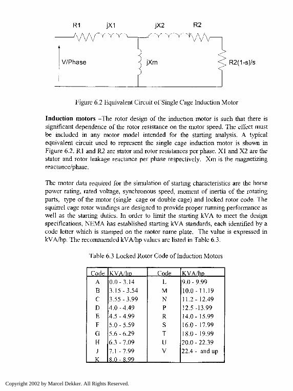
Figure 6.2 Equivalent Circuit of Single Cage Induction Motor
Induction motors -The rotor design of the induction motor is such that there issignificant dependence of the rotor resistance on the motor speed. The effect mustbe included in any motor model intended for the starting analysis. A typicalequivalent circuit used to represent the single cage induction motor is shown inFigure 6.2. Rl and R2 are stator and rotor resistances per phase. XI and X2 are thestator and rotor leakage reactance per phase respectively. Xm is the magnetizingreactance/phase.
The motor data required for the simulation of starting characteristics are the horsepower rating, rated voltage, synchronous speed, moment of inertia of the rotatingparts, type of the motor (single cage or double cage) and locked rotor code. Thesquirrel cage rotor windings are designed to provide proper running performance aswell as the starting duties. In order to limit the starting kVA to meet the designspecifications, NEMA has established starting kVA standards, each identified by acode letter which is stamped on the motor name plate. The value is expressed inkVA/hp. The recommended kVA/hp values are listed in Table 6.3.
Table 6.3 Locked Rotor Code of Induction Motors
CodeABCDEFGHJK
KVA/hD0.0-3.143.15-3.543.55-3.994.0-4.494.5-4.995.0-5.595.6-6.296.3-7.097.1 -7.998.0-8.99
CodeLMNPRSTUV
KVA/ho9.0-9.9910.0- 11.1911.2- 12.4912.5-13.9914.0- 15.9916.0- 17.9918.0- 19.9920.0-22.3922.4 - and up
Copyright 2002 by Marcel Dekker. All Rights Reserved.
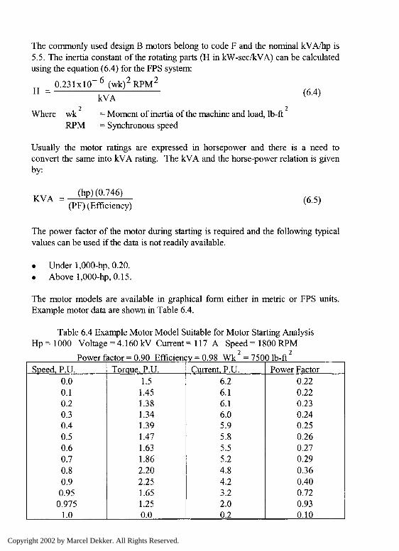
The commonly used design B motors belong to code F and the nominal kVA/hp is5.5. The inertia constant of the rotating parts (H in kW-sec/kVA) can be calculatedusing the equation (6.4) for the FPS system:
H =0.231xlO~6 (wk)2RPM2
kVA(6.4)
Where wk = Moment of inertia of the machine and load, Ib-ftRPM = Synchronous speed
Usually the motor ratings are expressed in horsepower and there is a need toconvert the same into kVA rating. The kVA and the horse-power relation is givenby:
KVA =(hp) (0.746)
(PF) (Efficiency)(6.5)
The power factor of the motor during starting is required and the following typicalvalues can be used if the data is not readily available.
• Under 1,000-hp, 0.20.• Above 1,000-hp, 0.15.
The motor models are available in graphical form either in metric or FPS units.Example motor data are shown in Table 6.4.
Table 6.4 Example Motor Model Suitable for Motor Starting AnalysisHp = 1000 Voltage = 4.160 kV Current = 117 A Speed = 1800 RPM
Power factor = 0.90 Efficiency = 0.98 Wk2 = 7500 Ib-ftSpeed, P.U.
0.00.10.20.30.40.50.60.70.80.9
0.950.975
1.0
Torque, P.U.1.5
1.451.381.341.391.471.631.862.202.251.651.250.0
Current, P.U.6.26.16.16.05.95.85.55.24.84.23.22.00.2
Power Factor0.220.220.230.240.250.260.270.290.360.400.720.930.10
Copyright 2002 by Marcel Dekker. All Rights Reserved.
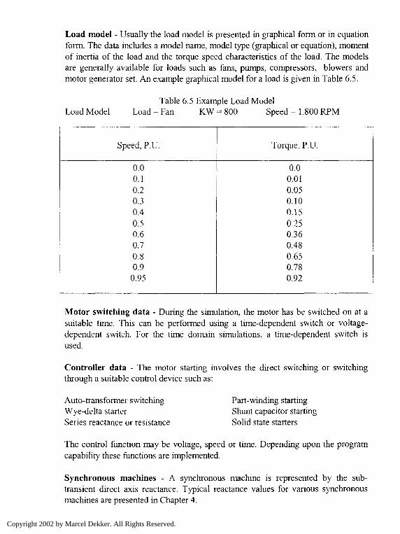
Load model - Usually the load model is presented in graphical form or in equationform. The data includes a model name, model type (graphical or equation), momentof inertia of the load and the torque speed characteristics of the load. The modelsare generally available for loads such as fans, pumps, compressors, blowers andmotor generator set. An example graphical model for a load is given in Table 6.5.
Load ModelTable 6.5 Example Load Model
Load = Fan KW = 800 Speed =1.800 RPM
Speed, P.U.
0.00.10.20.30.40.50.60.70.80.9
0.95
Torque, P.U.
0.00.010.050.100.150.250.360.480.650.780.92
Motor switching data - During the simulation, the motor has be switched on at asuitable time. This can be performed using a time-dependent switch or voltage-dependent switch. For the time domain simulations, a time-dependent switch isused.
Controller data - The motor starting involves the direct switching or switchingthrough a suitable control device such as:
Auto-transformer switchingWye-delta starterSeries reactance or resistance
Part-winding startingShunt capacitor startingSolid state starters
The control function may be voltage, speed or time. Depending upon the programcapability these functions are implemented.
Synchronous machines - A synchronous machine is represented by the sub-transient direct axis reactance. Typical reactance values for various synchronousmachines are presented in Chapter 4.
Copyright 2002 by Marcel Dekker. All Rights Reserved.
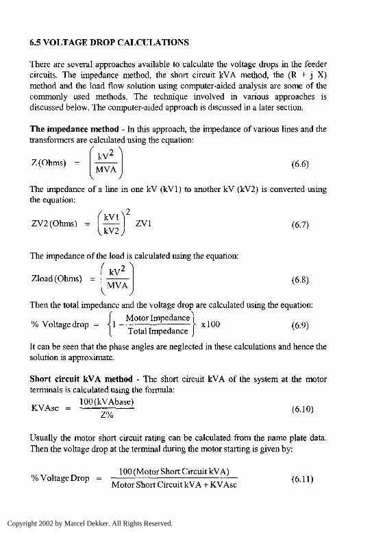
6.5 VOLTAGE DROP CALCULATIONS
There are several approaches available to calculate the voltage drops in the feedercircuits. The impedance method, the short circuit kVA method, the (R + j X)method and the load flow solution using computer-aided analysis are some of thecommonly used methods. The technique involved in various approaches isdiscussed below. The computer-aided approach is discussed in a later section.
The impedance method - In this approach, the impedance of various lines and thetransformers are calculated using the equation:
r2 X
Z(Ohms) =kV
MVAJ
(6.6)
The impedance of a line in one kV (kVl) to another kV (kV2) is converted usingthe equation:
s\
ZV2(Ohms) = (— ZV1 (6.7)
The impedance of the load is calculated using the equation:/ o
kV2
Zload(Ohms) =MVA
V J
(6.8)
Then the total impedance and the voltage drop are calculated using the equation:
I Motor Impedance ]% Voltage drop = \\ \ xlOO (69)
[ Total Impedance J
It can be seen that the phase angles are neglected in these calculations and hence thesolution is approximate.
Short circuit kVA method - The short circuit kVA of the system at the motorterminals is calculated using the formula:
100 (kV Abase)KVAsc = — z%— (6JO)
Usually the motor short circuit rating can be calculated from the name plate data.Then the voltage drop at the terminal during the motor starting is given by:
100 (Motor Short Circuit kVA)% Voltage Drop = (611)
Motor Short Circuit kVA +KVAsc v ' '
Copyright 2002 by Marcel Dekker. All Rights Reserved.
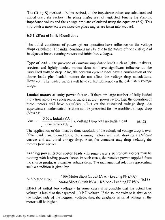
The (R + j X) method - In this method, all the impedance values are calculated andadded using the vectors. The phase angles are not neglected. Finally the absoluteimpedance values and the voltage drop are calculated using the equation (6.9). Thisapproach is more accurate since the phase angles are taken into account.
6.5.1 Effect of Initial Conditions
The initial conditions of power system operation have influence on the voltagedrops calculated. The initial conditions may be due to the nature of the existing loadin adjacent buses, running motors and initial bus voltages.
Type of load - The presence of constant impedance loads such as lights, resistors,reactors and lightly loaded motors does not have significant influence on thecalculated voltage drop. Also, the constant current loads have a combination of theabove loads plus loaded motors do not affect the voltage drop calculations.However, fully loaded motors will have certain influence on the calculated voltagedrops.
Loaded motors at unity power factor - If there are large number of fully loadedinduction motors or synchronous motors at unity power factor, then the operation ofthese motors will have significant effect on the calculated voltage drop. Anapproximate mathematical relation can be presented for the modified voltage drop(Vm) as:
0.65 x Initial kVA IVm = x Voltage Drop with no Initial Load (6.12)
Generator kVA J
The application of this must be done carefully, if the calculated voltage drop is over30%. Under such conditions, the running motors will stall drawing significantcurrent and additional voltage drop. Also, the contactor may drop isolating themotors from service.
Leading power factor motor loads - In some cases synchronous motors may berunning with leading power factor. In such cases, the reactive power supplied fromthe source produces a smaller voltage drop. The mathematical relation representingsuch a condition is given by:
100 (Motor Short Circuit kV A - Leading PF kV A)% Voltage Drop - —(613)
Motor Short Circuit kVA + KVAsc - Leading PF kVA v ' '
Effect of initial bus voltage - In some cases it is possible that the actual busvoltage is less than the expected 1.0 P.U voltage. If the source voltage is always onthe higher side of the nominal voltage, then the available terminal voltage at themotor will be higher.
Copyright 2002 by Marcel Dekker. All Rights Reserved.
6.6 CALCULATION OF ACCELERATION TIME
The acceleration time of the motor shaft during starting can be calculated by solvingthe equation of motion given by:
1 T dco
The time required to accelerate from the speed fo\ to &>2 is:
tm-) J d(Dt = ft - (6.15)
(T-T1)
In order to find the value of this integral, it is necessary to know the motor torque(T) and the load torque (Tl) as a function of speed. In the simplest case, when themotor torque and the load torque are constant, then:
T ( 0)2 ~col)A? = J — - - — (6.16)
(T-T1)
2 ? r Nw = - - <6-17>
The total inertia J is represented by Wk . Simplifying the equation (6.16) usingthese terms,
At = - (6.18)308(T-T1)
During the starting of a motor, the terminal voltage will drop and the correspondingtorque will be less. Therefore, suitable correction factor has to be applied to accountfor the torque reduction. The motor terminal voltage and the accelerating torque aregiven by :
Motor terminal voltage = V 1-Input kVA
Input kVA + KVAsc(6.19)
Where KVAsc is the short circuit rating of the source. The net motor torque (Tr)can be calculated by:
Copyright 2002 by Marcel Dekker. All Rights Reserved.

Tr = T [V in per unit]" (6.20)
The net accelerating torque is the difference between the resultant motor toque andthe load torque. In order to improve the accuracy of the calculated accelerationtime, a reduced time step is required. The calculation procedure is explained usingan example.
Example 6.3 - Consider a 500-hp, 460 V, 1170 rpm, 3 phase induction motor foran application with torque speed characteristics as shown in Table 6.6. Thecombined inertia of the motor shaft and the load is 3,500 Ibs-ft . The short circuitkVA of the system is 35,000 kVA. The input to the motor at rated load is 450 kVA.Calculate the acceleration time in seconds using a step-by-step approach.
Table 6.6 The Speed Torque Characteristics of the Motor and Load in P.U.
SpeedIncrement0 to 20%
20 to 40%40 to 60%60 to 80%80 to 100%
MotorTorque,%
84
93120175167
LoadTorque, %
58
203045
%kVA550
540525480350
Solution - One iteration of calculation is shown below and the table of results iscalculated using a spread sheet.
Voltage at the motor terminal before statingSpeed incrementMotor input kVA (5.5 x 450 kVA)
2475Motor terminal voltage = 105 1
2475 + 35000
= 105%= 20%= 2475 kVA
= 98.07%
Motor full load torque (5250 x 500 hp/1170 rpm) = 2239.3 Ib-ftNet torque (84% - 5%) = 79%Net torque (0.79 x 2239.3 Ib-ft) - 1769.1 Ib-ft
Tr - Tt [V in per unit]"
AAt = =308(T-T1)
= 1769.1 [0.9807]
3500 x l l70 *0.20
308x1759.1
= 1701.5 Ib-ft
= 1.5 second
This calculation can be repeated and the step-by-step results are presented in atable. The total delta t's are added to get the total starting time of the motor.
Copyright 2002 by Marcel Dekker. All Rights Reserved.

SpeedIncrementOto20%
20 to 40%40 to 60%60 to 80%80to100°/!
%kVA550540525480350
kVA24752430
2362521601575
%oflvttcrVdtege
98.07
98.1898.3698.90
100.478469
FV Torque
Lb-tt100110140200180
IVbtorTorque,%
8493120175167
LoadTorque,%
58203045
NetTorque,%
7985100145122
Net Tor.Lb-ft
1,769.061,903.422239.323,247.012,731.97
Delta tSeconds
1.501.40
1.190.820.97
Total starting time in seconds 5.88
6.7 MOTOR STARTING WITH LIMITED-CAPACITY GENERATORS
In smaller power systems with one or two generators, the source impedance issignificant and a motor starting will result in the drop in the speed of the generator.Usually, the generators are equipped with automatic voltage regulators andgovernors. The motor starting performance depends on the type of voltageregulator. With normal regulators there will be some voltage drop during the motorstarting. With high-speed regulators, the performance will be better and with extrahigh speed regulation will be still better. It is necessary to perform motor startingstudies modeling both the generator and motor to be started.
6.8 COMPUTER-AIDED ANALYSIS
In large-scale power systems with multiple generators and feedback networkconnections with various voltage levels, it is difficult to calculate the voltage dropsusing the above-mentioned approaches. Therefore, computer-aided approaches areused to calculate the required voltage drops. The motor to be started is representedusing the locked rotor impedance values and the power factor. The motor startingsolution is performed and the voltage drops at various bus locations are identified.Also, the voltage, current, speed and power factor of the motor to be started isavailable from the outputs.
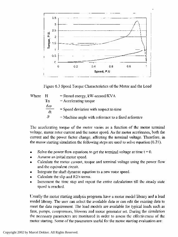
There are several programs available to perform the motor starting analysis. Inorder to perform the analysis the dynamic torque speed relation needs to beresolved. Figure 6.3 illustrates the torque speed characteristics of a typical inductionmotor. One is the torque characteristic of a motor and the other is the loadcharacteristic. The difference between the two torque curves represents the nettorque available to accelerate the motor. The point of intersection of these twocurves represents the steady state operating point. The dynamic equation of themotor starting function is given by:
a,Tn
2H(6.21)
Copyright 2002 by Marcel Dekker. All Rights Reserved.
Z>Q.
=J
O
3.5 -
3 -
2.5 -•
2 J
1.5 -
1 -
0.5
0 -
C) 0.2 0.4 0.6
Speed, P.U
0.8
Figure 6.3 Speed Torque Characteristics of the Motor and the Load
Where HTn
dt3
= Stored energy, kW-second/KVA= Accelerating torque
= Speed deviation with respect to time
= Machine angle with reference to a fixed reference
The accelerating torque of the motor varies as a function of the motor terminalvoltage, motor rotor current and the motor speed. As the motor accelerates, both thecurrent and the power factor change, affecting the terminal voltage. Therefore, inthe motor starting simulation the following steps are used to solve equation (6.21).
• Solve the power flow equations to get the terminal voltage at time t = 0.• Assume an initial motor speed.• Calculate the motor current, torque and terminal voltage using the power flow
and the equivalent circuit.• Integrate the shaft dynamic equation to a new rotor speed.• Calculate the slip and R2/s terms.• Increment the time step and repeat the entire calculations till the steady state
speed is reached.
Usually the motor starting analysis programs have a motor model library and a loadmodel library. The user can select the available data or can edit the existing data tomeet the data requirement. The load models are available for typical loads such asfans, pumps, compressors, blowers and motor generator set. During the simulationthe necessary parameters are monitored in order to assess the effectiveness of themotor starting. Some of the parameters useful for the motor starting evaluation are:
Copyright 2002 by Marcel Dekker. All Rights Reserved.
Bus voltage Motor speedMotor terminal voltage Motor input currentMotor torque Load torqueAccelerating torque Real power and reactive powerPower factor
The plots can be examined to evaluate the acceptance of the starting condition. Theprogram output report contains the following:
Branch loading data Pre-starting voltages Final voltage report
Using both the graphical and report results the performance of the motor startingcan be evaluated.
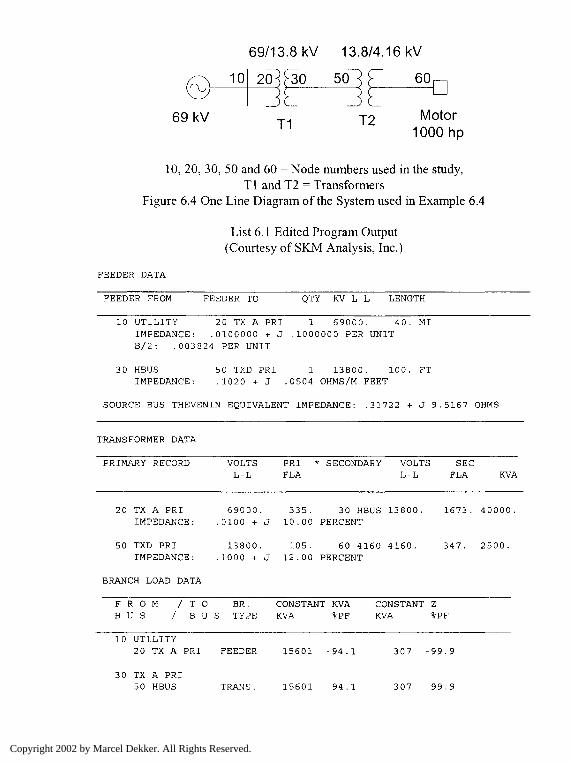
Example 6.4 - A one-line diagram of a power system with a 1000-hp motor isshown in Figure 6.4. The motor is to be started on line. The source impedance ofthe system at the 69 kV level is (0.3172 + j 9.5617) Ohm/phase. The step downtransformer is 40 MVA, 69/13.8 kV, 10% impedance on nameplate MVA. Themedium voltage transformer is 2.5 MVA, 13.8/4.16 kV, 12% impedance. Themotor and the load torque characteristics are given in the reproduced output of theinput data. Perform a motor starting study using a computer-aided program anddiscuss the results. Assume the cable and other necessary data.
Solution - The data is prepared interactively and the motor starting study isperformed. The Power Tools for Windows Program is used for the motor startingstudy [3]. The input data listing is presented as a part of the output. This enablesverification of the accuracy of the data. The input data include the source,transformer, cables, motor and the load models. The output includes the motorstarting characteristics in time domain and the performance at the operating point.
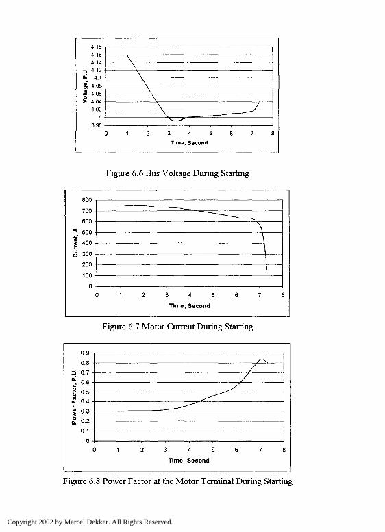
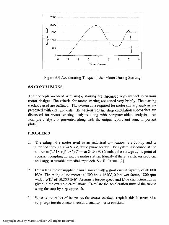
The time domain plot is presented for the motor speed in Figure 6.5. The motorspeed slowly increases to rated speed in 7.33 seconds. The motor terminalvoltage drops to 4 kV and then starts increasing, see Figure 6.6. The drop isaround 4% and is acceptable. The current during the starting is 6 P.U. and dropsto nominal value at the end of the start time and is shown in Figure 6.7. Themotor power factor is shown in Figure 6.8. The power factor increases from 0.2to 0.8 during the starting process. Finally, the accelerating torque is shown inFigure 6.9.
Copyright 2002 by Marcel Dekker. All Rights Reserved.
69 kV
69/1 3.8 kV
10 20^^30
_JLT1
13.8/4.16
— ) c —) CjrT2
kV
60nI I
Motor1000hp
10, 20, 30, 50 and 60 = Node numbers used in the study,Tl and T2 = Transformers
Figure 6.4 One Line Diagram of the System used in Example 6.4
List 6.1 Edited Program Output(Courtesy of SKM Analysis, Inc.)
FEEDER DATA
FEEDER FROM FEEDER TO QTY KV L-L LENGTH
10 UTILITY 20 TX A PRI 1 69000. 40. MIIMPEDANCE: .0100000 + J .1000000 PER UNITB/2: .003824 PER UNIT
30 HBUS 50 TXD PRI 1 13800. 100. FTIMPEDANCE: .1020 + J .0504 OHMS/M FEET
SOURCE BUS THEVENIN EQUIVALENT IMPEDANCE: .31722 + J 9.5167 OHMS
TRANSFORMER DATA
PRIMARY RECORD VOLTSL-L
PRI * SECONDARYFLA
VOLTSL-L
SECFLA KVA
20 TX A PRIIMPEDANCE:
69000.0100 + J
335. 30 HBUS 13800,10.00 PERCENT
1673. 40000,
50 TXD PRIIMPEDANCE:
13800..1000 + J
105. 60 4160 4160.12.00 PERCENT
347. 2500.
BRANCH LOAD DATA
F R O M / T O B R .B U S / B U S TYPE
CONSTANT KVAKVA %PF
CONSTANT ZKVA %PF
10 UTILITY20 TX A PRI FEEDER 15601 -94.1 307 -99.9
30 TX A PRI50 HBUS TRANS. 15601 -94.1 307 -99.9
Copyright 2002 by Marcel Dekker. All Rights Reserved.
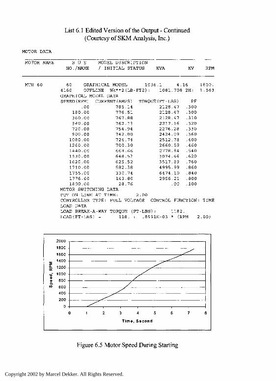
List 6.1 Edited Version of the Output - Continued(Courtesy of SKM Analysis, Inc.)
MOTOR DATA
MOTOR NAME B U SNO . /NAME
MODEL DISCRIPTION/ INITIAL STATUS KVA KV RPM
MTR 60 60 GRAPHICAL MODEL 1036.1 4.16 1800.4160 OFFLINE Wk**2(LB-FT2): 1081.708 2H: 1.563GRAPHICAL MODEL DATASPEED(RPM) CUF
.00180.00360.00540.00720 .00900.001080.001260.001440 .001530.001620.001710.001755.001776 .601800.00
MOTOR SWITCHING DATAPUT ON LINE AT TIME: 2.00CONTROLLER TYPE: FULL VOLTAGE CONTROL FUNCTION: TIMELOAD DATALOAD BREAK-A-WAY TORQUE (FT-LBS): 1182.LOAD(FT-LBS) = 118. + .8991E-03 * (RPM 2.00)
'(AMPS) TORQUE(FT-LBS)785.776,767.762.754.742 ,724 .700 .668.648 ,625.582.330.14328.
.14
.51
.88
.13
.94
.00
.74
.30
.66
.53
.52
.38
.74
.80
.76
2128212821282217.2276.2424.25122660277830743517499564742956
.47
.47
.47
.16
.28
.09
.78
.59
.84
.46
.89
.99
. 10
.21
.00
PF.300.300.310.320.330.360.400.460.540.620.760.860.840.800.100
5Q.QL
•a0)«o.co
°000
1800 -
1600
1400
1200 -
1000 -
800 -
600 -
400
200Q
^^^^
^^/
/
//
^^
^^0 1 2 3 4 5 6 7 8
Time, Second
Figure 6.5 Motor Speed During Starting
Copyright 2002 by Marcel Dekker. All Rights Reserved.
of 3O
1
0 5 10 15 20 25FREQUENCY NUMBER
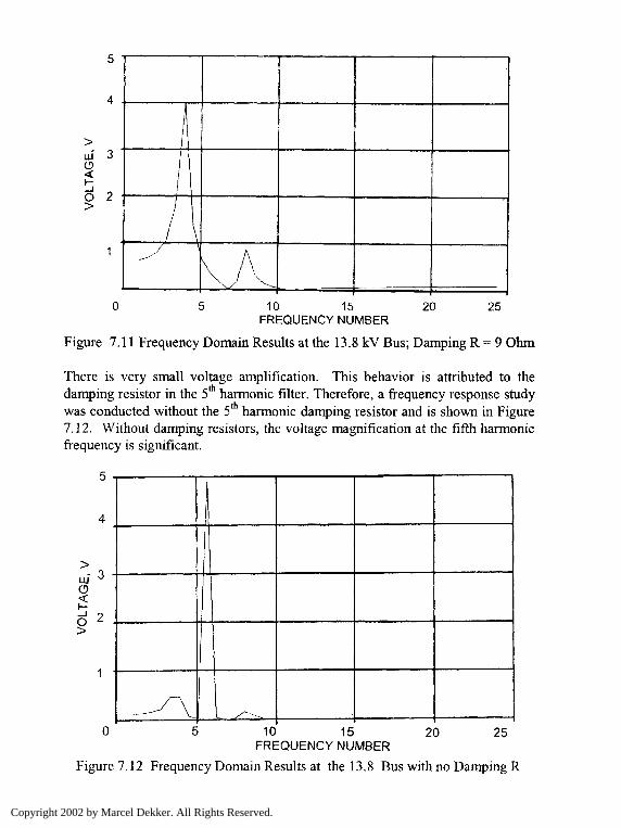
Figure 7.11 Frequency Domain Results at the 13.8 kV Bus; Damping R = 9 Ohm
There is very small voltage amplification. This behavior is attributed to thedamping resistor in the 5th harmonic filter. Therefore, a frequency response studywas conducted without the 5th harmonic damping resistor and is shown in Figure7.12. Without damping resistors, the voltage magnification at the fifth harmonicfrequency is significant.
r 3
0 5 10 15 20 25FREQUENCY NUMBER
Figure 7.12 Frequency Domain Results at the 13.8 Bus with no Damping R
Copyright 2002 by Marcel Dekker. All Rights Reserved.
z>aQj"O)ao
4 08 -
4 -
\\\\\\\ /
^~ — ̂0 1 2 3 4 5 6 7 8
Time, Second
Figure 6.6 Bus Voltage During Starting
Curr
ent
A
°nn
finn
Ann -
^nn
9nn
mn -
n
- — - ^\\
\
0 1 2 3 4 5 6 7 8
Time, Second
Figure 6.7 Motor Current During Starting
3 4 5
Time, Second
Figure 6.8 Power Factor at the Motor Terminal During Starting
Copyright 2002 by Marcel Dekker. All Rights Reserved.
3 4 5
Time, Second
Figure 6.9 Accelerating Torque of the Motor During Starting
6.9 CONCLUSIONS
The concepts involved with motor starting are discussed with respect to variousmotor designs. The criteria for motor starting are stated very briefly. The startingmethods used are outlined. The system data required for motor starting analysis arepresented with example data. The various voltage drop calculation approaches arediscussed for motor starting analysis along with computer-aided analysis. Anexample analysis is presented along with the output report and some importantplots.
PROBLEMS
1. The rating of a motor used in an industrial application is 2,500-hp and issupplied through a 24.9 kV, three phase feeder. The system impedance at thesource is (3.318 + J5.982) Ohm at 24.9 kV. Calculate the voltage at the point ofcommon coupling during the motor stating. Identify if there is a flicker problemand suggest suitable remedial approach. See Reference [2].
2. Consider a motor supplied from a source with a short circuit capacity of 40,000kVA. The rating of the motor is 1500 hp, 4.16 kV, 0.9 power factor, 1800 rpmwith a WK2 of 10,200 lb-ft2. Assume a torque speed and kVA characteristics asgiven in the example calculations. Calculate the acceleration time of the motorusing the step-by-step approach.
3. What is the effect of inertia on the motor starting? Explain this in terms of avery large inertia constant versus a smaller inertia constant.
Copyright 2002 by Marcel Dekker. All Rights Reserved.
4. What will happen if the speed torque characteristics of a motor load isnonlinear. Give an example practical load and mention its effect on the startingand operation of the motor. Hint - Air conditioner application.
5. A 2 MW, 4.16 kV, 1,800 rpm induction motor is running at the operatingpoint. Another motor is to be started in a nearby location with the torque speedcharacteristics and load characteristics as given in the typical data. The motorto be started is a 1.5 MW, 4.16 kV, 1200 rpm, three-phase induction motor.The short circuit rating of the source is 750 MVA. Simulate the system using amotor starting or dynamics program. Assess the starting condition andrecommend which remedial measures are needed, if any. State the assumptionsmade.
6. What is the difference between the simulation of a running motor and startingmotor using a dynamics program?
REFERENCES
1. ANSI/IEEE Standard 399, IEEE Recommended Practice for Power SystemAnalysis, 1990 (Brown Book).
2. M. K. Walker, "Electric Utility Flicker Limitations", IEEE Transactions onIndustry Applications, Vol.IA-15, No.6, November/December 1979, pp. 644-655.
3. Power Tools for Windows Program, SKM Analysis, Inc., Manhattan Beach,California.
Copyright 2002 by Marcel Dekker. All Rights Reserved.