motor solutions guide - mouser electronics · motor solutions guide 2011-9. driver sensor ... tip...
TRANSCRIPT

h t t p : / / w w w . s e m i c o n . t o s h i b a . c o . j p / e n gS E M I C O N D U C T O R
SYSTEM CATALOG
Motor Solutions Guide
2011-9
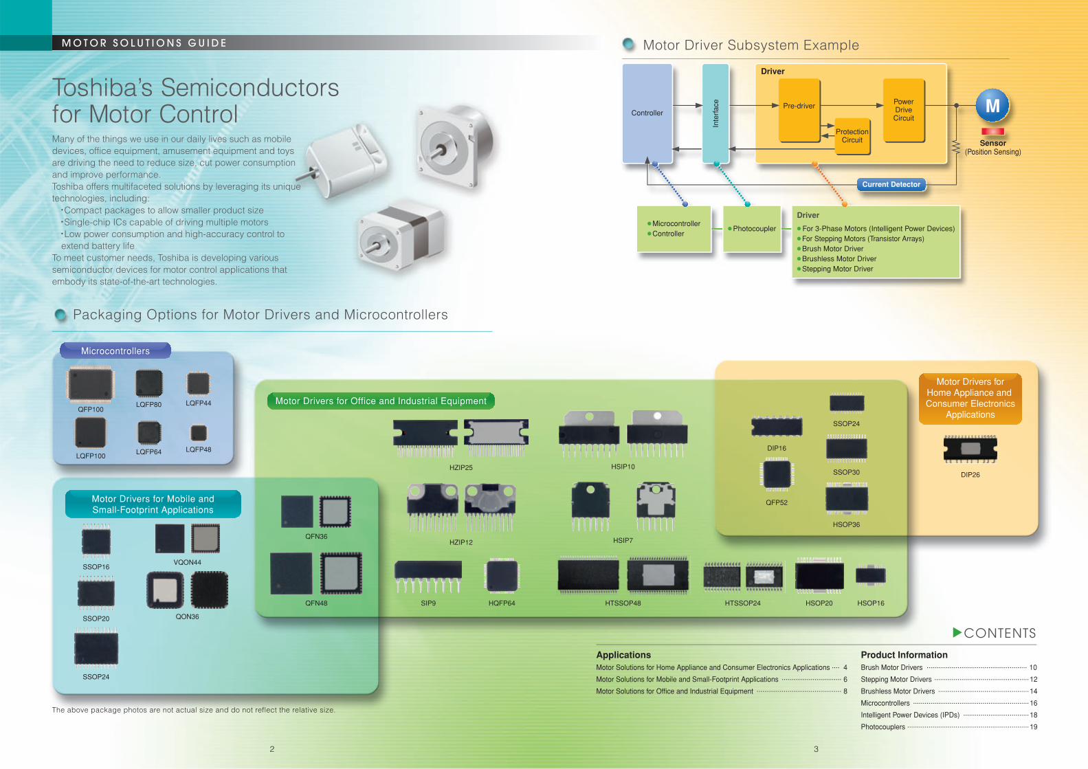
Driver
Sensor(Position Sensing)
● Photocoupler
Driver
● For 3-Phase Motors (Intelligent Power Devices)● For Stepping Motors (Transistor Arrays)● Brush Motor Driver ● Brushless Motor Driver● Stepping Motor Driver
● Microcontroller● Controller
Current Detector
Motor Driver Subsystem Example
Controller
Inte
rfac
e
ProtectionCircuit
Pre-driverPowerDriveCircuit
MToshiba’s Semiconductors for Motor Control
Packaging Options for Motor Drivers and Microcontrollers
ApplicationsMotor Solutions for Home Appliance and Consumer Electronics Applications .... 4
Motor Solutions for Mobile and Small-Footprint Applications ............................... 6
Motor Solutions for Office and Industrial Equipment ............................................ 8
Product InformationBrush Motor Drivers .................................................... 10
Stepping Motor Drivers .................................................12
Brushless Motor Drivers ...............................................14
Microcontrollers ............................................................16
Intelligent Power Devices (IPDs) ..................................18
Photocouplers ...............................................................19
SSOP20
SSOP24
HQFP64 HSOP20 HSOP16SIP9QFN48
QON36
The above package photos are not actual size and do not reflect the relative size.
HTSSOP48 HTSSOP24
Motor Drivers for Office and Industrial Equipment
Motor Drivers forHome Appliance and Consumer Electronics
Applications
Motor Drivers for Mobile andSmall-Footprint Applications
SSOP16
QFP100
LQFP100LQFP64
LQFP80 LQFP44
LQFP48
VQON44
QFN36HSIP7
QFP52
DIP16
HSOP36
SSOP24
SSOP30HZIP25
HZIP12
HSIP10
Microcontrollers
DIP26
Many of the things we use in our daily lives such as mobile devices, office equipment, amusement equipment and toys are driving the need to reduce size, cut power consumption and improve performance.Toshiba offers multifaceted solutions by leveraging its unique technologies, including:
● Compact packages to allow smaller product size● Single-chip ICs capable of driving multiple motors● Low power consumption and high-accuracy control to extend battery life
To meet customer needs, Toshiba is developing various semiconductor devices for motor control applications that embody its state-of-the-art technologies.
2 3

VSP
VST
FPWM VREF FG_OUT VM
TIP
FST1
LA1
CW_CCW
COM
OC
IR
W
V
U
SEL_LAP
BRAKE
TRE
LA2
FST2
Reference Voltage Circuit
+–
+–
+–
PWMControl
Startup TimeSetting
7-bit ADConverter
Startup CommutationFrequency Setting
1-Phase ExcitationControl Circuit
PWMSignal
Generator
TimingSetting
OvercurrentProtection CircuitTSD
ClockGenerator
REV
FG
CW/CCW
IDC
RES
Vrefout
GND
VCC
VSP
U
X
V
Y
W
Z
HWMHWPHVMHVPHUMHUP
OSC/ROSC/C
Position SensingSine-Wave
Matrix
Square-WaveMatrix
Control/Protection Circuits● Reset Circuit● Overcurrent Detection● Forward/Reverse Switching● Motor Rotation Direction
Detection● FG Signal
23
30
29
11
20
10
22
9
21
12
8
7
6
5
4
32
1
26
24
27
25
28
TEST0 VPPVM = 50 to 400 V
UVWXYZ
VU
HV
IUIVIW
AGND
TEST11TEST12
VCCVCC = 5 V
VREG
0.1μF
EP
OSCR
CW-CCWFG
TSPSDOSDISCK
DGND
TEST1TEST2TEST3
MCU
M
System Clock OSC
VectorComputation
OutputSignal
SHADCTimer
Reg.
MCU
PositionDetection
Circuit
ISD
GIN GOUT PH ALA LPF LA UL14131516171819
Output Stage● 120°/180° Switching● Programmable Dead Time● Gate Block● Active Side Switching
IPD
■ Sensorless PWM drive: The back-EMF voltage from the motor coil is sensed and fed back to the commutation signals.■ Sine-wave drive: The motor windings are energized with sine-wave currents to reduce vibration and acoustic noise.
Sine-wave PWM control is implemented as a hardware core.■ Lead angle control: Lead angle control and automatic lead angle correction help to improve motor efficiency.■ Vector control: The hardware specifically designed for vector control enables sensorless sine-wave drive.
Toshiba's Unique Motor Control Technologies
● Sine-wave current drive● Automatic lead angle correction● On-chip oscillator
(External resistors and capacitors required)● On-chip power source for Hall sensors● Programmable dead time● Dual-phase modulation● Package: SSOP30-P-300-0.65
● Vector control● Sensorless sine-wave control● On-chip oscillator
(External resistors required)● RPM control● Programmable dead time● Package: SSOP30-P-300-0.65
Sensorless Square-Wave PWM Three-Phase Brushless DC Motor Drivers (TB6633FNG/AFNG)
Sine-Wave PWM Three-Phase Brushless DC Motor Controllers (TB6584FNG/AFNG)
Sensorless Sine-Wave PWM Three-Phase Brushless DC Motor Controller (TC7600FNG)
● Sensorless PWM drive● Improved overlapping commutation
(135°/150° commutation)● Lead angle control● FNG: FG = 3 ppr
AFNG: FG = 1 ppr● Package: SSOP24-P-300-0.65A
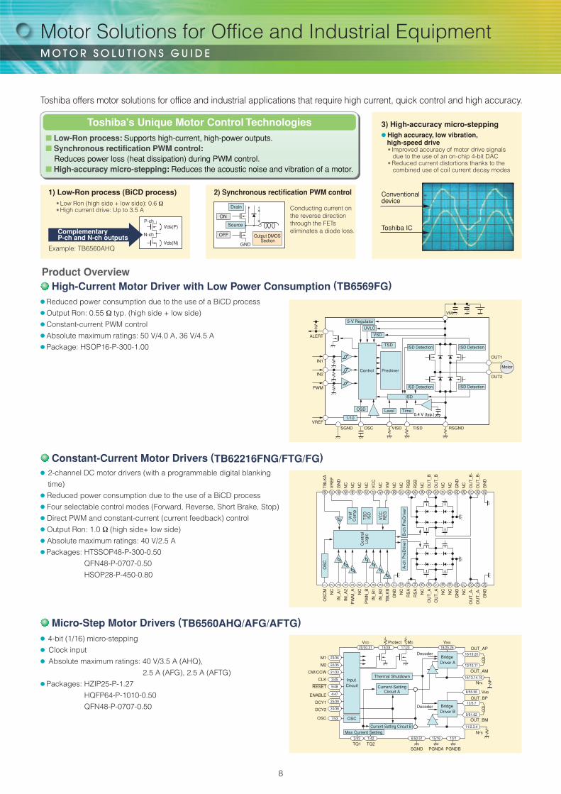
Product Overview
Toshiba offers a suite of motor solutions ideal for DC inverter applications that require low power consumption and quiet motor control, such as motor controllers, microcontrollers with an integrated vector engine and intelligent power devices (IPDs).
Motor Solutions for Home Appliance and Consumer Electronics Applications
4
DC Indoor Fan Motor
LouverMotor
FilterCleaner
Fan Motor
FilterCleanerActuator
Operation Commands
Operation Data
EEPROM(Data control)
Motor Driver
Two-Way ValveFour-Way Valve
LED LED Driver
PFC Circuit
Temperature Sensors(room temperature,
radiant heat,heat exchanger)
Motor ControllerIPDMotor Driver
Power Supply
Photocoupler
Compressor
Microcontroller
Fan Motor
Motor Controller
IPD
Operating Mode DisplayPower Level Display
Main Control
Remote Controller
Indoor Unit Outdoor Unit
Filter Cleaner Motors 1 & 2
Indoor Fan Motor Louver MotorIGBT/MOSFET Driver
Compressor Control
Motor ControlOutdoor Fan Motor 1
Outdoor Fan Motor 2
Microcontroller
Motor Driver
Motor
M
PLL WDT
POR/VLTD
OFD
ARMCortexTM-M3
Core
ROM
RAM
16-bitTimer
Encoderinput
Regulator
CG
I/O
VectorEngine PMD
12-bit ADC
SIO/UART
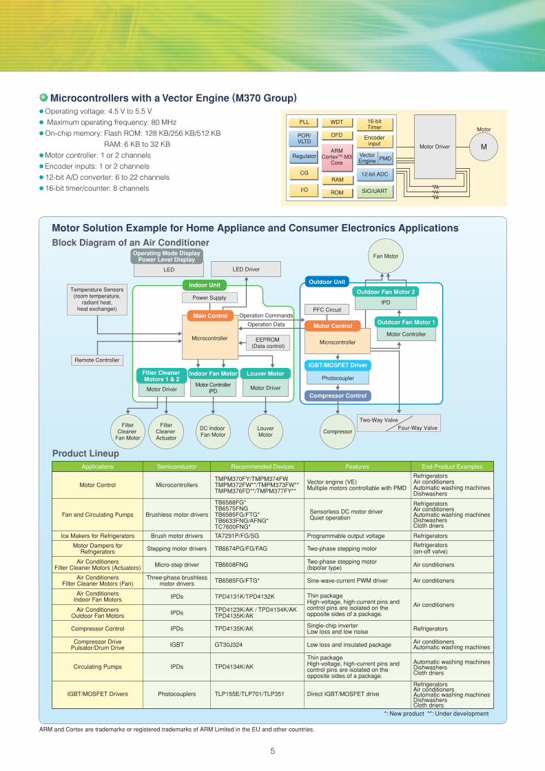
Applications Recommended DevicesSemiconductor Features End-Product Examples
Motor Control
Fan and Circulating Pumps
Ice Makers for Refrigerators
Motor Dampers forRefrigerators
Air ConditionersFilter Cleaner Motors (Actuators)
Air ConditionersFilter Cleaner Motors (Fan)
Air ConditionersIndoor Fan Motors
Air ConditionersOutdoor Fan Motors
Microcontrollers
Brushless motor drivers
Brush motor drivers
Stepping motor drivers
Micro-step driver
Three-phase brushlessmotor drivers
IPDs
IPDs
Compressor Control IPDs
*: New product **: Under development
Vector engine (VE)Multiple motors controllable with PMD
Sensorless DC motor driverQuiet operation
Programmable output voltage
Two-phase stepping motor
Two-phase stepping motor(bipolar type)
Sine-wave-current PWM driver
Thin packageHigh-voltage, high-current pins and control pins are isolated on the opposite sides of a package.
TMPM370FY/TMPM374FWTMPM372FW**/TMPM373FW**TMPM376FD**/TMPM377FY**
TB6588FG*TB6575FNGTB6585FG/FTG*TB6633FNG/AFNG*TC7600FNG*
TA7291P/FG/SG
TB6674PG/FG/FAG
TB6608FNG
TB6585FG/FTG*
TPD4131K/TPD4132K
TPD4135K/AK
TPD4123K/AK / TPD4134K/AKTPD4135K/AK
RefrigeratorsAir conditionersAutomatic washing machinesDishwashersCloth driers
Refrigerators
Refrigerators (on-off valve)
Air conditioners
Air conditioners
Single-chip inverterLow loss and low noise Refrigerators
Compressor DrivePulsator/Drum Drive IGBT GT30J324 Low loss and insulated package
Direct IGBT/MOSFET drive
Air conditionersAutomatic washing machines
Circulating Pumps IPDs TPD4134K/AK
IGBT/MOSFET Drivers Photocouplers TLP155E/TLP701/TLP351
Thin packageHigh-voltage, high-current pins and control pins are isolated on the opposite sides of a package.
Automatic washing machinesDishwashersCloth driers
RefrigeratorsAir conditionersAutomatic washing machinesDishwashersCloth driers
Air conditioners
RefrigeratorsAir conditionersAutomatic washing machinesDishwashers
Product Lineup
Microcontrollers with a Vector Engine (M370 Group)● Operating voltage: 4.5 V to 5.5 V● Maximum operating frequency: 80 MHz● On-chip memory: Flash ROM: 128 KB/256 KB/512 KB
RAM: 6 KB to 32 KB● Motor controller: 1 or 2 channels● Encoder inputs: 1 or 2 channels● 12-bit A/D converter: 6 to 22 channels● 16-bit timer/counter: 8 channels
Motor Solution Example for Home Appliance and Consumer Electronics ApplicationsBlock Diagram of an Air Conditioner
ARM and Cortex are trademarks or registered trademarks of ARM Limited in the EU and other countries.
5

PWMF
PWME
MCK RFAB01B02RFB
A02A01
x 2
x 3
RFCE02E01
PGND1F02F01
VM1
VM3
PWMA/CK1MO1
PWMB/EN1
GNDLDDATACK STBY VCC
12-bit Serial Decoder
6-bit Micro-StepStepping Motor Driver
PWM Constant-CurrentH-Bridge Driver
Direct PWMH-Bridge Driver
TSD
TSD UVD
ISD
VCC STB PWM NC PGND 02 02 VM
CG
WDT NANOFLASHTM
ROM
16-bitTimer
(10 ch)
ARMCortexTM-M3
Core
External Bus
RAM
SSP(1 ch)
2 Phase(4 ch)
H-PPG(2 ch)
I2C/SIO(2 ch)
SIO/UART(5 ch)
12-bit ADC(15 ch)
10-bit DAC(2 ch)
I/O(86)
DMAC(4 ch)
16 15 14 13 12 11 10 9
GND IN1 IN2 NC PGND 01 01 VM
1 2 3 4 5 6 7 8
H-SW
H-SWLogic
UVD
Toshiba offers motor solutions ideal for mobile and small-footprint applications that require low power consumption and small form factor.
■ Reduced power consumption due to the use of a new process: Products with an LDMOS output stage featuring low power consumption
■ Significantly reduced power loss and heat dissipation from the output stage: TB6614FNG: Output Ron = 0.3 Ω(typ.)■ High-speed PWM control: TB6614FNG: fPWM = Up to 400 kHz■ Small packages: Leadless QON and QFN packages■ Ultrasonic-motor control and piezoelectric actuator support: PPG outputs with 6-ns resolution.
Toshiba's Unique Motor Control Technologies
● Absolute maximum ratings: 6 V/0.8 A ● 8-channel single-chip driver (Independently controllable)
● Channels A, B, C and D: 6-bit micro-step STM
(Configurable to operate as four independent DCM drivers)● Channel E: PWM constant-current H-bridge driver● Channels F, G and H: Direct PWM H-bridge drivers
● 3-wire serial interface● Standby function● Thermal shutdown circuitry, undervoltage lockout circuitry● Package: VQON44-P-0606-0.4
● Operating voltage: 2.7 to 3.6 V● Maximum operating frequency: 54 MHz● On-chip memory: Flash ROM: 512 KB/256 KB
RAM: 32 KB ● 12-bit AD converter: 15 channels● 10-bit DA converter: 2 channels● High-resolution PPG output: 2 channels (Resolution: 6 ns max)● Two-phase pulse counter: 4 channels● Serial interfaces: SIO/UART: 5 channels
I2C (100 kHz/400 kHz)/SIO: 2 channels
SSP: 1 channel● Package: P-TFBGA113-0606-0.50AZ
ARM and Cortex are trademarks or registered trademarks of ARM Limited in the EU and other countries.NANO FLASH is a registered trademark of Toshiba Corporation.
Product OverviewDC Motor Driver for Low-Power Applications (TB6614FNG)
The TB6614FNG is a DC motor driver using low-ON-resistance LDMOS transistors at the output stage. The IN1 and IN2 input terminals allow selection of one of the four modes: Forward, Reverse, Short Brake or Stop.● Output current: Io = 1.2 A (typ.), 3.2 A (repetitive pulse peak)● Operating voltage: Vcc = 2.7 to 5.5 V
VM = 2.5 to 13.5 V● Output Ron: 0.3 Ω typ. (high side + low side)● Direct PWM, fPWM max = 400 kHz● Standby function● Thermal shutdown circuitry, overcurrent protection circuitry,
undervoltage lockout circuitry● Package: SSOP16-P-225-0.65
Motor Control Microcontrollers (TMPM341FDXBG, TMPM341FYXBG <Under Development> )
8-Channel Motor Driver for a Digital Still Camera (DSC) (TB6613FTG)
Motor Solutions for Mobile and Small-Footprint Applications
6
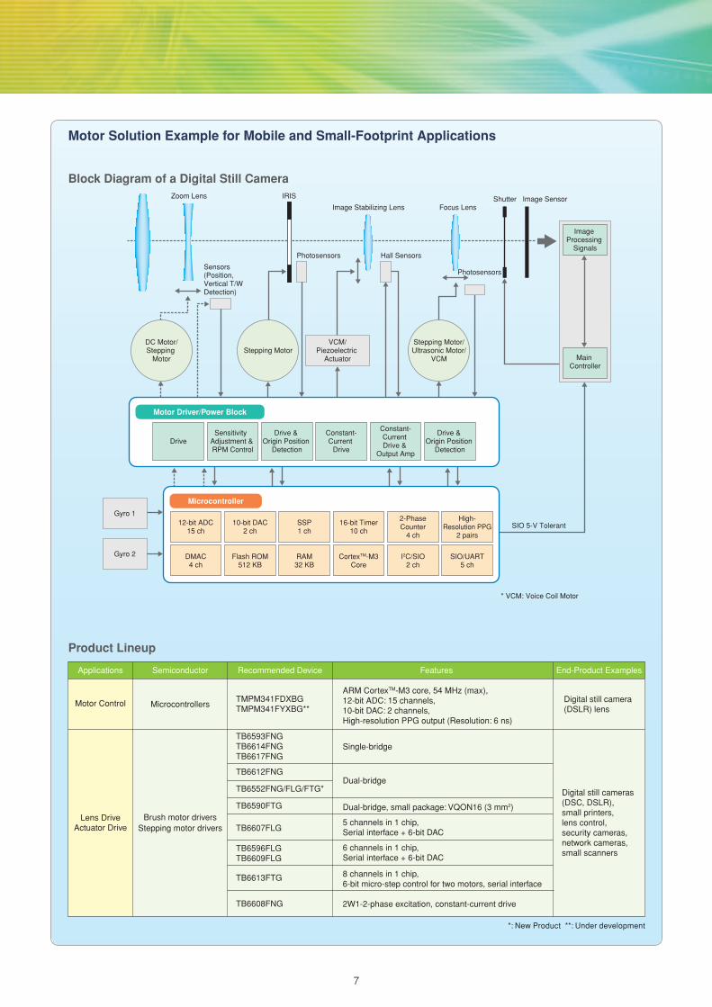
Motor Solution Example for Mobile and Small-Footprint Applications
Block Diagram of a Digital Still Camera
Stepping Motor/Ultrasonic Motor/
VCMStepping Motor
DC Motor/Stepping
Motor
VCM/Piezoelectric
Actuator
ImageProcessing
Signals
MainController
SIO 5-V Tolerant
* VCM: Voice Coil Motor
Zoom Lens
Sensors(Position,Vertical T/W Detection)
Photosensors Hall Sensors
Photosensors
IRIS
Image Stabilizing Lens Focus LensShutter Image Sensor
Microcontroller
Motor Driver/Power Block
12-bit ADC15 ch
10-bit DAC2 ch
SSP1 ch
16-bit Timer10 ch
2-PhaseCounter
4 ch
High-Resolution PPG
2 pairs
DMAC4 ch
Flash ROM512 KB
RAM32 KB
CortexTM-M3Core
I2C/SIO2 ch
SIO/UART5 ch
DriveSensitivity
Adjustment & RPM Control
Drive & Origin Position
Detection
Constant-Current
Drive
Constant-CurrentDrive &
Output Amp
Drive & Origin Position
Detection
Gyro 1
Gyro 2
Applications Recommended DeviceSemiconductor Features End-Product Examples
Motor Control
Lens DriveActuator Drive
Microcontrollers
Brush motor driversStepping motor drivers
*: New Product **: Under development
ARM CortexTM-M3 core, 54 MHz (max),12-bit ADC: 15 channels,10-bit DAC: 2 channels,High-resolution PPG output (Resolution: 6 ns)
Single-bridge
Dual-bridge
Dual-bridge, small package: VQON16 (3 mm2)
5 channels in 1 chip,Serial interface + 6-bit DAC
6 channels in 1 chip,Serial interface + 6-bit DAC
8 channels in 1 chip, 6-bit micro-step control for two motors, serial interface
2W1-2-phase excitation, constant-current drive
TMPM341FDXBGTMPM341FYXBG**
TB6593FNGTB6614FNGTB6617FNG
TB6612FNG
TB6552FNG/FLG/FTG*
TB6607FLG
TB6596FLGTB6609FLG
TB6613FTG
TB6608FNG
TB6590FTG
Digital still cameras (DSC, DSLR),small printers,lens control,security cameras,network cameras,small scanners
Digital still camera (DSLR) lens
Product Lineup
7
N-ch
P-ch
Vds(N)
Vds(P) Source
Drain
GND
OFF
ON
Output DMOS Section
×
×
OSD
1/10
TSD
VSD
UVLO
5-V Regulator
Control Predriver
ISD Detection
VM
ISD DetectionISD Detection
ISD
ALERT
IN1
IN2
PWM
VREFSGND OSC VISD TISD RSGND
OUT2
OUT1
ISD Detection
Time0.4 V (typ.)
Level
Decoder
DecoderOUT_AP
OUT_AM
NFA
OUT_BP
OUT_BM
NFB
VMB
11/2.3.4
8/55.56
M1
M2
CW/CCW
CLK
RESET
ENABLE
DCY1
DCY2
OSC
23/36
22/35
21/33
3/45
5/48
4/47
25/39
24/38
7/53
TQ1 TQ26/50.511/42
PGNDASGND
15/16
PGNDB
10/12/43
VDD Protect MD VMA
20/30.31 18/25.2617/2319/28
BridgeDriver A
BridgeDriver B
Max Current SettingCurrent-Setting Circuit B
InputCircuit
OSC
Motor
OS
CM
1
NC
2
IN_A
13
IM_A
24
PW
M_A
5
NC
6
PW
N_B
7
IN_B
18
IN_B
29
TB
LKB
10
GN
D11
NC
12
RS
A13
RS
A14
NC
15
OU
T_A
16
OU
T_A
17
NC
18
NC
19
GN
D20
NC
21
OU
T_A
-22
OU
T_A
-23
GN
D24
TB
LKA
48
VR
EF
47
GN
D46
NC
45
NC
44
NC
43
NC
42
VC
C41
NC
40
VM
39
NC
38
NC
37
RS
B36
RS
B35
NC
34
OU
T_B
33
OU
T_B
32
NC
31
NC
30
GN
D29
NC
28
OU
T_B
-27
OU
T_B
-26
GN
D25
OS
C
Vre
fC
omp
B-c
h P
reD
river
A-c
h P
reD
river
14/13.14.15
13/10.11
12/6.7
9/61.62
16/19.20
TS
DIS
D
VC
CR
EG
Thermal Shutdown
Con
trol
Logi
c
Current-SettingCircuit A
Toshiba offers motor solutions for office and industrial applications that require high current, quick control and high accuracy.
● 2-channel DC motor drivers (with a programmable digital blanking
time)● Reduced power consumption due to the use of a BiCD process● Four selectable control modes (Forward, Reverse, Short Brake, Stop)● Direct PWM and constant-current (current feedback) control● Output Ron: 1.0 Ω (high side+ low side)● Absolute maximum ratings: 40 V/2.5 A● Packages: HTSSOP48-P-300-0.50
QFN48-P-0707-0.50
HSOP28-P-450-0.80
● 4-bit (1/16) micro-stepping● Clock input● Absolute maximum ratings: 40 V/3.5 A (AHQ),
2.5 A (AFG), 2.5 A (AFTG)● Packages: HZIP25-P-1.27
HQFP64-P-1010-0.50
QFN48-P-0707-0.50
■ Low-Ron process: Supports high-current, high-power outputs.■ Synchronous rectification PWM control:
Reduces power loss (heat dissipation) during PWM control.■ High-accuracy micro-stepping: Reduces the acoustic noise and vibration of a motor.
Toshiba's Unique Motor Control Technologies
1) Low-Ron process (BiCD process) 2) Synchronous rectification PWM control
3) High-accuracy micro-stepping
● Low Ron (high side + low side): 0.6 Ω● High current drive: Up to 3.5 A
Complementary P-ch and N-ch outputs
Conducting current on the reverse direction through the FETs eliminates a diode loss.
Example: TB6560AHQ
Conventional device
Toshiba IC
● Reduced power consumption due to the use of a BiCD process● Output Ron: 0.55 Ω typ. (high side + low side)● Constant-current PWM control● Absolute maximum ratings: 50 V/4.0 A, 36 V/4.5 A● Package: HSOP16-P-300-1.00
Micro-Step Motor Drivers (TB6560AHQ/AFG/AFTG)
Constant-Current Motor Drivers (TB62216FNG/FTG/FG)
High-Current Motor Driver with Low Power Consumption (TB6569FG)Product Overview
● High accuracy, low vibration, high-speed drive● Improved accuracy of motor drive signals
due to the use of an on-chip 4-bit DAC ● Reduced current distortions thanks to the
combined use of coil current decay modes
Motor Solutions for Office and Industrial Equipment
8

Motor Solutions for Office and Industrial Equipment
Block Diagram of a Printer
Power Supply Photocoupler
A/D Converter Sensors
FixationHeater
Toner Detection
Motor Driver Controller IC
Input Section
Indicator
Image Output Engine Control Section
HeadMotor
PaperTransport
Motor
AutoPaper Feed
Motor
Motor Driver
Motor Driver
Motor Driver
ScannerLight Source
LEDDriver
SteppingMotor
MotorDriver
System Control
Interface Control
System Control
Printer Head
Paper Unit (Transport/Sort)
CCD AnalogFront-End
External Interface
DrumUnit
Applications Recommended DeviceSemiconductor Features End-Product Examples
Image Output Engine Control Section
Fans
Image Output Engine Control Section
Image Output Engine Control Section,Input Section
Heater Control
Stepping Motor Drivers/Brush Motor Drivers
SteppingMotor Drivers
Brushless Motor Drivers
Brush Motor Drivers
Photocouplers
*: New product
Single full bridge, output voltage control
Single full bridge
Single full bridge, direct PWM control
Single full bridge, Constant-current PWM control/direct PWM controlSingle full bridge, emergency output, Direct PWM control
Dual full bridge
Sensorless control
Sine-wave PWM controllers
Sine-wave PWM controller, RPM control
Controller
Clock input, micro-stepping drive (4W1-2-phase excitation)Clock input, micro-stepping drive (W1-2-phase excitation)
Pin-, functionally- and package-compatible version of TB62214A with low Ron
Phase inputs, micro-stepping drive (W1-2-phase excitation)
Pin-, functionally- and package-compatible version of TB62218A with low Ron
Phase inputs, 1-2-phase excitation
Phase inputs, 1-2-phase excitation, BiCD process,Four H-bridgesControls up to four brush DC motors or up to two stepping motors.
Single full bridge, emergency output, Direct PWM control,Constant-current PWM control
Single full bridge, emergency output,Direct PWM control, constant-current PWM control,Reference voltage output
Dual full bridge, Constant-current control/direct PWM control,Programmable digital blanking time
TA8428K/FGTA8429HQ
TB6572AFGTB6603FTG*
TB6560AHQ/AFG/AFTG*TB62209FGTB62211FNG*TB62214AFG*/AFTG*/AFNG*
TB6549FG/PG/HQTB6568KQ*TB6643KQ*
TA7291SG (J)/FG/P
TB6559FG
TB6642FG*
TB6561NG/FG
TB6588FG
TB6551FG
TB6604FTG*
TB6615PG
TB62212FTAG/FNG*
TLP360J/TLP560J
TB62215AFG*/AFTG*/AFNG*
TB62213AFG*/AFTG*/AFNG*
TB62206FGTB62208FG/FTG/FNG*
TB62210FNG*TB6562ANG/AFGTB62218AFG*/AFTG*/AFNG*
TB62216FNG*/FTG*/FG*
TB6569FG*
TB6641FG*
Plain paper copiers (PPCs), printers, scanners, fax machines, vending machines, ATMs, amusement equipment, card readers, bank note recognition machines, etc.
Industrial fans
Office printers
Plain paper copiers (PPCs), printers, scanners, fax machines, vending machines, ATMs, amusement equipment, card readers, robots, bank note recognition machines, etc.
Multifunction printers
Product Lineup
9
B r u s h M o t o r D r i v e r s
IN2
IN1
OUT2
OUT1
5 V Regulator
UVLO
VSD
TSD
ISD
GND
ISD Detection
ISD DetectionISD Detection
VM
ISD Detection
Control Predriver Motor
OSD
1/10
TSD
VSD
UVLO
5 V Regulator
Control Predriver
ISD Detection
VM
ISD DetectionISD Detection
ISD
ALERT
IN1
IN2
PWM
VREFSGND OSC VISD TISD RSGND
OUT2
OUT1
ISD Detection
Time0.4V(typ.)
Level
Motor
15 V 25 V to 30 V 50 V 6 V to 15 V 40 V
TA8429HQ
HZIP12
TB6549HQ
HZIP25
TB6569FG
HSOP16
TB6641FG
HSOP16
TB6642FG
HSOP16
TB6643KQ
HSIP7
TB62212FTAG/FNG
QFN48-P-0707-0.50/HTSSOP48-P-300-0.50
Large Mode
TB62212FTAG/FNG
QFN48-P-0707-0.50/HTSSOP48-P-300-0.50
Small Mode
TB62216FTG/FNG/FG
QFN48-P-0707-0.50/HTSSOP48-P-300-0.50/
HSOP28-P-450-0.80
TB6612FNG
SSOP24
TB6568KQ
HSIP7
TB6549FG/PG
HSOP20/DIP16
TA8428K
HSIP7
TA7267BP
HSIP7
TB6614FNG
SSOP16
TB6593FNG
SSOP20
TB6559FG
HSOP16
TB6617FNG
SSOP16
TA7291P
HSIP10
TA8428FG
HSOP20
TB6561FG/NG
SSOP16/SDIP24
TB6552FNG/FLG/
FTGSSOP16/QON24/QFN24
TB6590FTG
VQON16
TA7291FG/SG
HSOP16/SIP9
Ratings
≥4.0 A
4.0 Ato
3.0 A
3.0 Ato
2.0 A
≤1.5 A
1 Channel 2 Channels 4 Channels
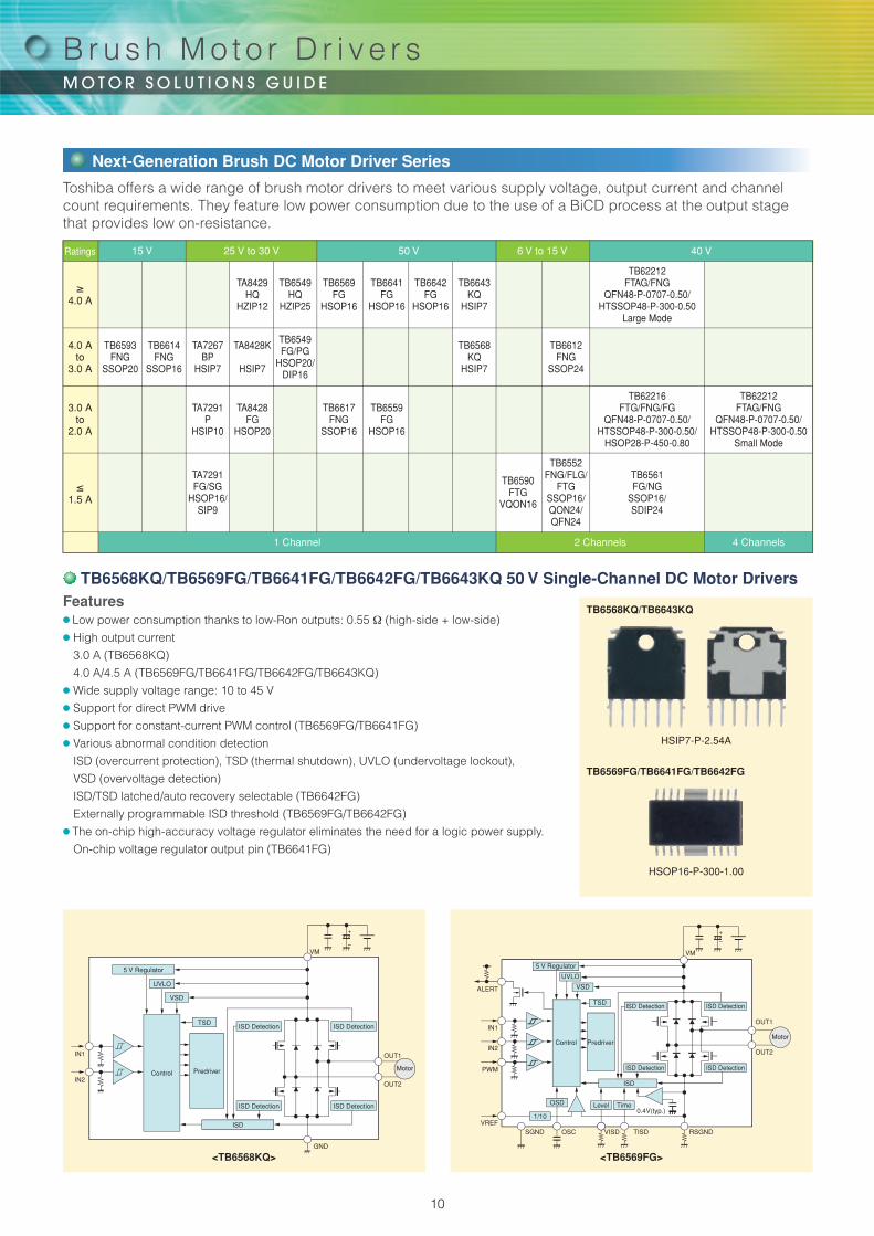
Features● Low power consumption thanks to low-Ron outputs: 0.55 Ω (high-side + low-side)● High output current
3.0 A (TB6568KQ)
4.0 A/4.5 A (TB6569FG/TB6641FG/TB6642FG/TB6643KQ)● Wide supply voltage range: 10 to 45 V● Support for direct PWM drive● Support for constant-current PWM control (TB6569FG/TB6641FG)● Various abnormal condition detection
ISD (overcurrent protection), TSD (thermal shutdown), UVLO (undervoltage lockout),
VSD (overvoltage detection)
ISD/TSD latched/auto recovery selectable (TB6642FG)
Externally programmable ISD threshold (TB6569FG/TB6642FG)● The on-chip high-accuracy voltage regulator eliminates the need for a logic power supply.
On-chip voltage regulator output pin (TB6641FG)
HSIP7-P-2.54A
TB6568KQ/TB6643KQ
HSOP16-P-300-1.00
TB6569FG/TB6641FG/TB6642FG
<TB6568KQ> <TB6569FG>
Toshiba offers a wide range of brush motor drivers to meet various supply voltage, output current and channel count requirements. They feature low power consumption due to the use of a BiCD process at the output stage that provides low on-resistance.
TB6568KQ/TB6569FG/TB6641FG/TB6642FG/TB6643KQ 50 V Single-Channel DC Motor Drivers
Next-Generation Brush DC Motor Driver Series
10
TSD
ISD
16VCC STB MOD NC PGND 02 02 VM
15 14 13 12 11 10 9
GND PWM IN1 IN2 PGND 01 01 VM
1 2 3 4 5 6 7 8
H-SWControlLogic
UVD
TA8428FG/K
TA8429HQ
TB6549FG/PG/HQ
TB6617FNG
TB6559FG
TB6568KQ
TB6643KQ*
TB6569FG/TB6641FG*
TB6642FG*
TB6561NG/FG
TB62216FNG/FTG/FG*
TB62212FTAG
TB62212FNG
TB6552FNG/FLG/FTG*
TB6590FTG
TB6593FNG
TB6612FNG
TB6614FNG
2.4 A/3.0 A
4.5 A
3.5 A/3.5 A/4.5 A
2.0 A
2.5 A
3.0 A
4.0 A/4.5 A
4.0 A/4.5 A
4.0 A/4.5 A
1.5 A
4.0 A/2.0 A(DC)1.8 A/1.5 A(ST)
4.0 A/2.0 A(DC)1.8 A/1.5 A(ST)
2.5 A
1.0 A
0.5 A
3.2 A
2.8 A
3.2 A
Auto
Auto
Auto
Auto
Latched
AutoAuto
–
Latched
Auto
Auto
Auto
Latched
Latched
Latched
Auto/Latched
Auto
Latched
Latched
Auto
Auto
Latched
Latched
Latched
Auto/Latched
Auto
Latched
Latched
–
–
–
Auto
Auto
Auto
Auto
Auto
HSOP20-P-450-1.00/HSIP7-P-2.54
HZIP12-P-1.78B
HSOP20-P-450-1.00/DIP16-P-300-2.54A/HZIP25-P-1.00F
SSOP16-P-225-0.65B
HSOP16-P-300-1.00
HSIP7-P-2.54A
HSIP7-P-2.54A
HSOP16-P-300-1.00
HSOP16-P-300-1.00
SDIP24-P-300-1.78/SSOP30-P-375-1.00
QFN48-P-0707-0.50
HTSSOP48-P-300-0.50
HTSSOP48-P-300-0.50/QFN48-P-0707-0.50/HSOP28-P-450-0.80
SSOP16-P-225-0.65B/QON24-P-0505-0.50/WQFN16-3030-0.5-0.3
VQON16-P-0303-0.50
SSOP20-P-225-0.65A
SSOP24-P-300-0.65A
SSOP16-P-225-0.65B
–
–
Y
Y
Y
Y
Y
Y
Y
Y
Y
Y
Y
Y
Y
Y
Y
Y
–
–
–
–
Y
–
–
Y
–
–
Y
Y
Y
–
–
–
–
–
30 V
30 V
30 V
50 V
50 V
50 V
50 V
50 V
50 V
40 V
40 V
40 V
40 V
15 V
6 V
15 V
15 V
15 V
1 ch
1 ch
1 ch
SSOP16-P-225-0.65B
1 ch
1 ch
1 ch
1 ch
1 ch
1 ch
2 ch
2 ch/4 ch
2 ch/4 ch
2 ch
2 ch
Abbreviations: ISD: Overcurrent protection circuitry, TSD: Thermal shutdown circuitry, Auto: Automatic recovery, Latched: Latched recovery, DC: DC motor driver, ST: Stepping motor driver
*: New product
2 ch
1 ch
2 ch
1 ch
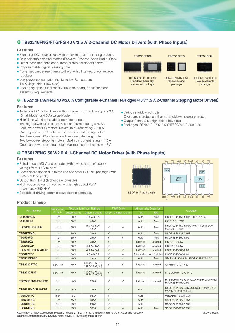
TB62216FNG/FTG/FG 40 V/2.5 A 2-Channel DC Motor Drivers (with Phase Inputs)
TB62212FTAG/FNG 40 V/2.0 A Configurable 4-Channel H-Bridges (40 V/1.5 A 2-Channel Stepping Motor Drivers)
TB6617FNG 50 V/2.0 A 1-Channel DC Motor Driver (with Phase Inputs)
Absolute Maximum Ratings PWM Drive Abnormality Detection
Supply Voltage Output Current Direct Constant-Current TSD ISDNumber of
CircuitsPart Number Packages
TB62216FNG
HTSSOP48-P-300-0.50Standard thermally enhanced package
TB62216FTG
QFN48-P-0707-0.50Space-saving
package
TB62216FG
HSOP28-P-450-0.80Flow-solderable
package
Features● 2-channel DC motor drivers with a maximum current rating of 2.5 A● Four selectable control modes (Forward, Reverse, Short Brake, Stop) ● Direct PWM and constant-current (current feedback) control● Programmable digital blanking time● Power sequence-free thanks to the on-chip high-accuracy voltage
regulator● Low power consumption thanks to low-Ron outputs:
1.0 Ω (high-side + low-side)● Packaging options that meet various pc board, application and
assembly requirements
Features● 4-channel DC motor drivers with a maximum current rating of 2.0 A
(Small Mode) or 4.0 A (Large Mode)● H-bridges with 6 selectable operating modes
Two high-power DC motors: Maximum current rating = 4.0 AFour low-power DC motors: Maximum current rating = 2.0 AOne high-power DC motor + one low-power stepping motorTwo low-power DC motor + one low-power stepping motorTwo low-power stepping motors: Maximum current rating = 1.5 AOne high-power stepping motor: Maximum current rating = 1.8 A
● Various shutdown circuits: Overcurrent protection, thermal shutdown, power-on reset
● Output Ron: 2.2 Ω (high side + low side)● Packages: QFN48-P-0707-0.50/HTSSOP48-P-300-0.50
Features● Rated at up to 50 V and operates with a wide range of supply
voltage from 4.5 V to 45 V.● Saves board space due to the use of a small SSOP16 package (with
0.65-mm lead pitch).● Output Ron: 1.4 Ω (high-side + low-side)● High-accuracy current control with a high-speed PWM
(fPWM max = 350 kHz)● Capable of driving ceramic piezoelectric actuators.
Product Lineup
11
RS
VCC
VM
OSCM
Output Control
Motor
VIN
Vref
IN_B2IN_B1
PHASE_BIN_A2IN_A1
PHASE_A
VMRDetect
STANDBY-
ParallelInput
RS
VCC
VM
OSCM
Output Control
Motor
VM
Vref
CLKD_MODE2D_MODE1
MO_OUT
ENABLECW/CCW
VMRDetect
RESET
ENABLE
STANDBY-
OSC
Vref
OSC
Vref
DetectionCircuitH-Bridge x 2
H-Bridge x 2Detection
Circuit
Current-SettingCircuit
μStepDecoder
Current Feedback Circuit
Current-SettingCircuit
Current Feedback Circuit
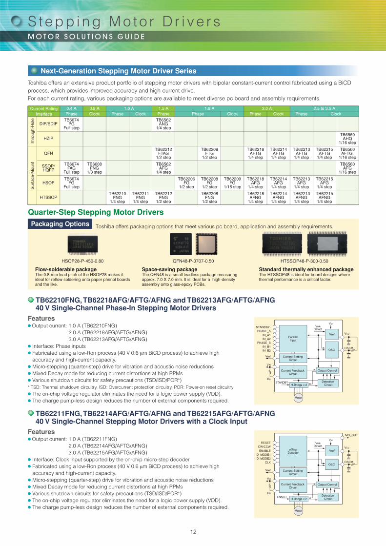
Features● Output current: 1.0 A (TB62211FNG)
2.0 A (TB62214AFG/AFTG/AFNG)3.0 A (TB62215AFG/AFTG/AFNG)
● Interface: Clock input supported by the on-chip micro-step decoder● Fabricated using a low-Ron process (40 V 0.6 μm BiCD process) to achieve high
accuracy and high-current capacity.● Micro-stepping (quarter-step) drive for vibration and acoustic noise reductions● Mixed Decay mode for reducing current distortions at high RPMs● Various shutdown circuits for safety precautions (TSD/ISD/POR*)● The on-chip voltage regulator eliminates the need for a logic power supply (VDD).● The charge pump-less design reduces the number of external components required.
0.4 APhase
0.8 AClock
1.0 APhase Clock
1.5 APhase Phase
1.8 AClock
2.0 APhase Clock Phase
2.5 to 3.5 AClock
TB6674PG
Full step
TB6562ANG
1/4 step
TB6560AHQ
1/16 step
TB6560AFTG
1/16 step
TB62215AFTG
1/4 step
TB62213AFTG
1/4 step
TB62214AFTG
1/4 step
TB62218AFTG
1/4 step
TB62208FTG
1/2 step
TB62212FTAG
1/2 step
TB6560AFG
1/16 step
TB6562AFG
1/4 step
TB6608FNG
1/8 step
TB6674FAG
Full step
TB62215AFG
1/4 step
TB62215AFNG
1/4 step
TB62213AFG
1/4 step
TB62213AFNG
1/4 step
TB62214AFG
1/4 step
TB62214AFNG
1/4 step
TB62218AFG
1/4 step
TB62209FG
1/16 step
TB62208FG
1/2 step
TB62206FG
1/2 step
TB6674FG
Full step
TB62218AFNG
1/4 step
TB62208FNG
1/2 step
TB62212FNG
1/2 step
TB62211FNG
1/4 step
TB62210FNG
1/4 step
Current Rating
DIP/SDIP
HZIP
QFN
SSOP/HQFP
HSOP
HTSSOP
Interface
Thr
ough
-Hol
eS
urfa
ce-M
ount
Features● Output current: 1.0 A (TB62210FNG)
2.0 A (TB62218AFG/AFTG/AFNG)3.0 A (TB62213AFG/AFTG/AFNG)
● Interface: Phase inputs● Fabricated using a low-Ron process (40 V 0.6 μm BiCD process) to achieve high
accuracy and high-current capacity.● Micro-stepping (quarter-step) drive for vibration and acoustic noise reductions● Mixed Decay mode for reducing current distortions at high RPMs● Various shutdown circuits for safety precautions (TSD/ISD/POR*)* TSD: Thermal shutdown circuitry, ISD: Overcurrent protection circuitry, POR: Power-on reset circuitry● The on-chip voltage regulator eliminates the need for a logic power supply (VDD).● The charge pump-less design reduces the number of external components required.
TB62210FNG, TB62218AFG/AFTG/AFNG and TB62213AFG/AFTG/AFNG40 V Single-Channel Phase-In Stepping Motor Drivers
TB62211FNG, TB62214AFG/AFTG/AFNG and TB62215AFG/AFTG/AFNG40 V Single-Channel Stepping Motor Drivers with a Clock Input
Toshiba offers packaging options that meet various pc board, application and assembly requirements.
Space-saving packageThe QFN48 is a small leadless package measuring approx. 7.0 X 7.0 mm. It is ideal for a high-density assembly onto glass-epoxy PCBs.
Standard thermally enhanced packageThe HTSSOP48 is ideal for board designs where thermal performance is a critical factor.
HSOP28-P-450-0.80 QFN48-P-0707-0.50 HTSSOP48-P-300-0.50
Packaging Options
Quarter-Step Stepping Motor Drivers
Toshiba offers an extensive product portfolio of stepping motor drivers with bipolar constant-current control fabricated using a BiCD process, which provides improved accuracy and high-current drive.For each current rating, various packaging options are available to meet diverse pc board and assembly requirements.
Next-Generation Stepping Motor Driver Series
Flow-solderable packageThe 0.8-mm lead pitch of the HSOP28 makes it ideal for reflow soldering onto paper phenol boards and the like.
S t e p p i n g M o t o r D r i v e r s
12

H-SW H-SW H-SW
H-SW
H-SW
H-SW
H-SW H-SW
H-SW H-SW
H-SW
H-SW
H-SW
H-SW
H-SW
H-SW
H-SW
H-SW
H-SW
H-SW
H-SW
H-SW
H-SW
H-SW
Stepper Stepper
Stepper Stepper Stepper
ParallelOperation
ParallelOperation
ParallelOperation
ParallelOperation
LargeDC Motor
LargeDC Motor
Small DC Motor Small DC Motor
Small DC Motor
Small DC Motor
Small DC Motor
Small DC Motor
LargeDC Motor
SmallStepping Motor
SmallStepping Motor
SmallStepping Motor
SmallStepping Motor
LargeStepping Motor
ParallelOperationParallel
Operation Stepper Stepper
Stepper Stepper Stepper
Auto
Latched
Auto
Latched
Latched
Latched
Latched
Latched
Auto
Latched
Latched
Latched
Latched
Auto
Latched
Latched
Auto
Latched
Latched
Latched
Latched
Latched
–
Latched
Latched
Latched
Latched
–
Full step
1/4 step
1/4 step
1/2 step
1/2 step
1/2 step
1/4 step
1/4 step
1/8 step
1/4 step
1/16 step
1/4 step
1/4 step
1/16 step
Phase
Phase
Phase
Phase
Phase
Phase
Phase
Phase
Clock
Clock
Clock
Clock
Clock
Clock
TB6674PG/FG/FAG
TB62210FNGTB6562ANG/AFG
TB62212FTAG/FNG
TB62206FG
TB62208FG/FTG/FNG
TB62218AFG/AFTG/AFNGTB62213AFG/AFTG/AFNGTB6608FNGTB62211FNGTB62209FGTB62214AFG/AFTG/AFNGTB62215AFG/AFTG/AFNGTB6560AHQ/AFG/AFTG
24 V
40 V
40 V
40 V
40 V
40 V
40 V
40 V
15 V
40 V
40 V
40 V
40 V
40 V
0.4 A/0.4 A/0.2 A
1.0 A
1.5 A
4.0 A/2.0 A (DC)1.8 A/1.5 A (ST)
1.8 A
1.8 A
2.0 A
3.0 A
0.8 A
1.0 A
1.8 A
2.0 A
3.0 A
3.5 A/2.5 A/2.5 A
Y
Y
–
Y
Y
Y
Y
Y
Y
Y
Y
Y
Y
–
DIP16-P-300-2.54A/HSOP16-P-300-1.00/SSOP16-P-225-1.00A
P-HTSSOP24-0508-0.65-001
SDIP24-P-300-1.78/SSOP30-P-375-1.00
QFN48-P-0707-0.50/HTSSOP48-P-300-0.50
HSOP20-P-450-1.00
HSOP28-P-450-0.80/QFN48-P-0707-0.50/HTSSOP48-P-300-0.50
HSOP28-P-450-0.80/QFN48-P-0707-0.50/HTSSOP48-P-300-0.50
HSOP28-P-450-0.80/QFN48-P-0707-0.50/HTSSOP48-P-300-0.50
SSOP20-P-225-0.65A
P-HTSSOP24-0508-0.65-001
HSOP36-P-450-0.65
HSOP28-P-450-0.80/QFN48-P-0707-0.50/HTSSOP48-P-300-0.50
HSOP28-P-450-0.80/QFN48-P-0707-0.50/HTSSOP48-P-300-0.50
HZIP25-P-1.27/HQFP64-P-1010-0.50/QFN48-P-0707-0.50
Abbreviations: POR: Power-on reset, ISD: Overcurrent protection circuitry, TSD: Thermal shutdown circuitry, Auto: Automatic recovery, Latched: Latched recovery, DC: DC motor driver, ST: Stepping motor driver
Absolute Maximum Ratings Detection Circuits
Output Breakdown Output Current ISDPOR TSDInterface Stepping
ModePart Number Packages
1.5 A/ch
Unipolarconstant-voltage
drive
1.5 A/ch
0.5 A/ch
0.5 A/ch
50 V/80 V
50 V/80 V
50 V
50 V
4
7
8
TD62064APG/BP1GTD62064AFG/BFGTD62308APG/BP1GTD62308AFG/BFGTD62003APG/TD62004APGTD62003AFG /TD62004AFG TD62083APG/TD62084APGTD62083AFG/TD62084AFGTD62083AFNG/TD62084AFNG
DIP16-P-300-2.54A
HSOP16-P-300-1.00
DIP16-P-300-2.54A
HSOP16-P-300-1.00
DIP16-P-300-2.54A
SOP16-P-225-1.27
DIP18-P-300-2.54D
SOP18-P-375-1.27
SSOP18-P-225-0.65
Active-high transistor array
Active-low transistor array
Active-high transistor array
Active-high transistor array
Absolute Maximum Ratings
Output Voltage Output Current# of Circuits PackagePart Number Structure/Configuration Remarks
TB62212FTAG/FNG 40 V/2.0 A Configurable 4-Channel H-Bridges(40 V/1.5 A 2-Channel Stepping Motor Drivers)
Half-Step Stepping Motor Drivers
The TB62212FTAG/FNG contain four channels of H-bridges, making it possible to drive up to two stepping motors or up to four brush DC motors simultaneously. They can also be configured as a dual brush DC motor driver with a maximum current rating of 4.0 A.
Features● Supports full-step and half-step drives in Stepping mode.● H-bridges with 6 selectable operating modes
Two high-power DC motors: Maximum current rating = 4.0 A
Four low-power DC motors: Maximum current rating = 2.0 A
One high-power DC motor + one low-power stepping motor
Two low-power DC motor + one low-power stepping motor
Two low-power stepping motors: Maximum current rating = 1.5 A
One high-power stepping motor: Maximum current rating = 1.8 A● Various shutdown circuits: Overcurrent protection, thermal shutdown,
power-on reset● Output RON: 2.2 Ω (high side + low side)● Packages: QFN48-P-0707-0.50, HTSSOP48-P-300-0.50
Transistor arrays designed for stepping motor driving are available with a variety of functions, circuit counts, voltage and current ratings, packages and so on. Small, surface-mount SSOP packages help reduce the size of end products.
Transistor Array Series
Product Lineup
Product Lineup
13

TC7600FNG
Sine-wave drive
Square-wave drive
TB6584FNG/AFNGBuilt-in OSC & Hall amp
Auto lead angle control
Sensor-lessSine-wave control
Sine-wave controlWith FLL/PLL
Sine-wave control
SensorlessSquare-wave control
Square-wavecontrol
TB6551FGTB6556FG
RPM control
TB6585FG
TB6585FTG
(45 V/1.8 A)
(45 V/1.0 A)
TB6575FNG TB6633FNG/AFNGDriver
Per
form
ance
Driver (25 V/1.0 A)
TB6588FG
Driver (50 V/2.5 A)
TB6586FG/AFG/BFG Controller
TB6572AFGTB6604FTG
TB6603FTG
REV
FG
CW/CCW
IDC
RES
Vrefout
GND
VCC
VSP
U
X
V
Y
W
Z
HWMHWPHVMHVPHUMHUP
OSC/ROSC/C
Position EstimationSine-Wave
Matrix
Square-WaveMatrix
Control and Protection Circuits● Reset Circuit● Overcurrent Detection● Forward/Reverse Rotation● Motor Rotation Direction Detection● FG Signal
23
30
29
11
20
10
22
9
21
12
8
7
6
5
4
32
1
26
24
27
25
28
TEST0 VPPVM = 50 to 400 V
UVWXYZ
VU
HV
IUIVIW
AGND
TEST11TEST12
VCCVCC = 5 V
VREG
0.1 μF
EP
OSCR
CW-CCWFG
TSPSDOSDISCK
DGND
TEST1TEST2TEST3
MCU
M
System Clock OSC
VectorComputation
OutputSignals
SHADCTimer
Reg.
DUTY
MCU
GIN GOUT PH ALA LPF LA UL14131516171819
Output Stage● 120°/180° Switching● Programmable Dead Time● Gate Block● Active Side Switching
IPD
Leveraging sensorless drive and sine-wave drive technologies, Toshiba has been developing a broad array of brushless DC motor drivers ideal for applications that require low power consumption and silent operation.
Features● Sine-wave drive helps to reduce acoustic
noise significantly, compared to square-wave (120-degree) drive.
● The lead angle and PWM control capabilities help to improve efficiency and reduce power consumption.
● The lead angle is programmable between 0° and 58° in 32 discrete steps, making it possible to control a motor efficiently through appropriate output driver selection.
● Dead-time insertion is incorporated to prevent cross conduction of high-side and low-side drivers.
● Overcurrent protection, undervoltage lockout and reverse rotation detection
● Small package: SSOP30-P-300-0.65
Features● Sine-wave drive can be used for sensorless
control of three-phase brushless DC motors.● Sine-wave drive helps to reduce acoustic
noise and vibration significantly, compared to square-wave (120-degree) drive.
● Small package: SSOP30-P-300-0.65
TC7600FNG 5 V/2 mA Sensorless Sine-Wave PWM Three-Phase Brushless DC Motor Controller
TB6584FNG/AFNG 16.5 V/2 mA Sine-Wave PWM Three-Phase Brushless DC Motor Controllers
Brushless Motor Controller and Driver Series
Product Roadmap
B r u s h l e s s M o t o r D r i v e r s
14

VSP
Speed Control Input (Analog Voltage)
FPWM VREF FG_OUT VM
TIPVREF
FST
LA
CW_CCW
PGNDSGNDOSC_ROSC_C
COM
OC
IR
W
V
U
SEL_LAP
BRAKE
TRE
SLOP
Reference Voltage Circuit
PWMControl
Startup TimeSetting
7-bit ADConverter
Startup CommutationFrequency Setting
1-phase ExcitationControl Circuit
PWMSignal
Generator
TimingSetting
OvercurrentProtection
Circuit
TSD
ISD
ClockGenerator
+–
+–
+–
PositionDetection
Circuit
MCU
HWM
VSPCW/CCW
RESET
FG
HWP
HVM
HVP
HUM
HUP
OSC/R
OSC/C
+–
+
–
+
–
+
–
+–
+–
1,36
5,Fin
35
34
33
32
30
31
18,19
13
12
9
3
4
14
15
16
17
8
7
29 28 27 26 25 24 23 22 21
2
GIN+ GIN- GOUT PH LPF IV LA
Vrefout
Vrefout
Vrefout
VM
U
V
P-GNDMLTR
3 ppr
S-GND
W
IR
RS
Pin 29
UL LL
Sine-Wave Generation Circuit
LockProtection
Setting
ChargePump TSD
PH
System Clock
LPFLimit(H)
4.4 V Regulator
Limit(L)
Motor
Motor
Features● Sine-wave drive helps to reduce acoustic
noise and vibration significantly, compared to square-wave (120-degree) drive.
● Lead angle control helps to improve efficiency.
● The on-chip integration of output drivers reduces the number of external components required.TB6585FG: 45 V/1.8 ATB6585FTG: 45 V/1.0 A
● Output RON: 0.7 Ω typ. (high side + low side)
● Small packagesTB6585FG: HSOP36-P-450-0.65TB6585FTG: QFN48-P-0707-0.5
Features● Combines sensorless drive with PWM drive,
facilitating the use of smaller motors (without Hall sensors) and reducing power consumption.
● Three-phase, full-wave sensorless drive eliminates the need for position sensors, reducing wires between a motor and a motor driver.
● The on-chip integration of output drivers reduces the number of external components required.TB6633FNG/AFNG: 25 V/1.0 A
● The lap turn-on function provides a quiet motor drive.
● FG signal according to the rotation speedTB6633FNG: 3 pulses per electrical degreeTB6633AFNG: 1 pulse per electrical degree
● Small packageSSOP24-P-300-0.65A
TB6551FG
TB6556FG
TB6586FG/AFG/BFG
TB6585FG/FTG *
TB6584FNG/AFNG
TB6572AFG
TB6603FTG
TB6604FTG
TC7600FNG
TB6575FNG
TB6588FG
TB6633FNG/AFNG *
Absolute Maximum Ratings
Supply Voltage Output Current
12 V 2 mA
Function
Controller
Part Number Commutation Hall Input Packages
Sine-wave Hall IC SSOP24-P-300-1.00
12 V 2 mAController Sine-wave Hall IC SSOP30-P-375-1.00
18 V 35 mAController Square-wave (150˚) Hall IC/Hall element SSOP24-P-300-1.00B
45 V 1.8 A/1.0 ADriver Sine-wave Hall IC/Hall element HSOP36-P-450-0.65/QFN48-P-0707-0.50
18 V 2 mAController Sine-wave Hall IC/Hall element SSOP30-P-300-0.65
30 V 20 mAPre-Driver Sine-wave Hall element QFP52-P-1010-0.65
30 V 20 mAPre-Driver Sine-wave Hall element QFN36-P-0606-0.50
30 V 20 mAPre-Driver Sine-wave Hall element QFN48-P-0707-0.50
5.5 V 2 mAController Sine-wave Sensorless SSOP30-P-300-0.65
5.5 V 20 mAController Square-wave (142˚) Sensorless SSOP24-P-300-0.65A
50 V 2.5 ADriver Square-wave (150˚) Sensorless HSOP36-P-450-0.65
25 V 1.0 ADriver Square-wave (150˚) Sensorless SSOP24-P-300-0.65A
*: New product
TB6585FG/FTG 45 V/1.8 A/1.0 A Sine-Wave PWM Three-Phase Brushless DC Motor Drivers
TB6633FNG/AFNG 25 V/1.0 A Sensorless PWM Three-Phase Brushless DC Motor Drivers
Product Lineup
15
TLCS-870/X Core: 20 MHz28 to 80-pin packages
8 KB to 120 KB (Mask / OTP / Flash ROM)
PMD2Sensored sine-wave
motor drive120˚ square-wave
motor drive
PMD2 plusMultiple sine-wave lookup tables
TLCS-870/C1 Core: 8 MHz48-pin package
32-KB ROM (Flash)
ARM CortexTM-M3 Core: 80 MHzVector Engine
VectorEngine
FunctionalEnhancements
Speed-up
TMPM370FY
Larger ROM
TMPM376FD** TMPM377FY**
100-pin, 512 KB
100-pin, 256 KB
PMD 2-ch
80-pin, 256 KB
PMD 2-ch
PMD 2-ch
More I/O interfaces
M370 Group++144-pin, 512 KB
PMD 3-ch
Smaller packages
TMPM372FW** TMPM373FW** TMPM374FWPMD 1-ch PMD 1-ch PMD 1-ch
++: Under planning **: Under development
CAN controller
M370 Group++ M370 Group++100-pin, 512KB 144-pin, 512KB
PMD 3-chPMD 2-ch
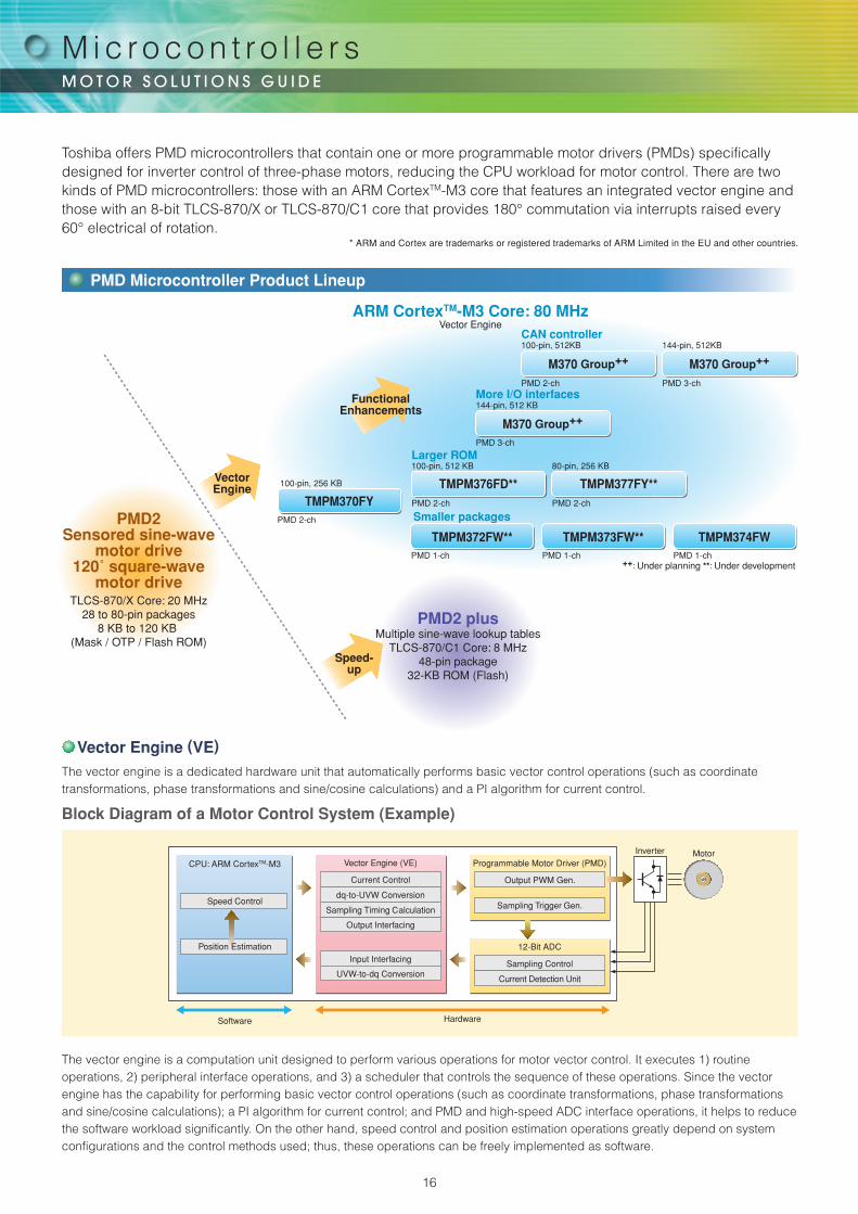
The vector engine is a computation unit designed to perform various operations for motor vector control. It executes 1) routine operations, 2) peripheral interface operations, and 3) a scheduler that controls the sequence of these operations. Since the vector engine has the capability for performing basic vector control operations (such as coordinate transformations, phase transformations and sine/cosine calculations); a PI algorithm for current control; and PMD and high-speed ADC interface operations, it helps to reduce the software workload significantly. On the other hand, speed control and position estimation operations greatly depend on system configurations and the control methods used; thus, these operations can be freely implemented as software.
The vector engine is a dedicated hardware unit that automatically performs basic vector control operations (such as coordinate transformations, phase transformations and sine/cosine calculations) and a PI algorithm for current control.
Block Diagram of a Motor Control System (Example)
CPU: ARM CortexTM-M3
Speed Control
Position Estimation
Vector Engine (VE)
Current Control
Sampling Timing Calculation
dq-to-UVW Conversion
Output Interfacing
Input Interfacing
UVW-to-dq Conversion
Software Hardware
Programmable Motor Driver (PMD)
Output PWM Gen.
Sampling Trigger Gen.
12-Bit ADC
Sampling Control
Current Detection Unit
Inverter Motor
Toshiba offers PMD microcontrollers that contain one or more programmable motor drivers (PMDs) specifically designed for inverter control of three-phase motors, reducing the CPU workload for motor control. There are two kinds of PMD microcontrollers: those with an ARM CortexTM-M3 core that features an integrated vector engine and those with an 8-bit TLCS-870/X or TLCS-870/C1 core that provides 180° commutation via interrupts raised every 60° electrical of rotation.
* ARM and Cortex are trademarks or registered trademarks of ARM Limited in the EU and other countries.
Vector Engine (VE)
PMD Microcontroller Product Lineup
M i c ro c o n t ro l l e r s
16

PLL10 MHz WDT
POR/VLTD
OFD
ARMCortexTM-M3
Core
ROM
RAM
16-bitTimer
EncoderInput
Regulator
CG
I/O
VectorEngine PMD
12-bit ADC
SIO/UART
● Packages● TMPM372FWUG: LQFP64-P-1010-0.50E● TMPM373FWDUG: LQFP48-P-0707-0.50C● TMPM374FWUG: LQFP44-P-1010-0.80A
PMD microcontrollers with a vector engineHigh-efficiency motor control that reduces the CPU workload
TMPM370FYDFG
TMPM370FYFG
TMPM372FWUG **
TMPM373FWDUG **
TMPM374FWUG
TMPM376FDDFG **
TMPM376FDFG **
TMPM377FYDFG **
TMPM377FYFG **
ROM(KB)
MotorController
(ch)
Flash 256
Flash 256
Flash 128
Flash 128
Flash 128
Flash 512
Flash 512
Flash 256
Flash 256
2
2
1
1
1
2
2
2
2
Maximum Operating Frequency
(MHz)
80
80
80
80
80
80
80
80
80
Part Number12-Bit
A/D Converter (Conversion Time)
EncoderInput Logic
(ch)
I/O Ports(ch)
Package
22 (2 μs)
22 (2 μs)
11 (2 μs)
7 (2 μs)
6 (2 μs)
22 (2 μs)
22 (2 μs)
11 (2 μs)
11 (2 μs)
2
2
1
1
1
2
2
2
2
76
76
53
37
33
82
82
63
63
QFP100-P-1420-0.65Q
LQFP100-P-1414-0.50H
LQFP64-P-1010-0.50E
LQFP48-P-0707-0.50C
LQFP44-P-1010-0.80A
QFP100-P-1420-0.65Q
LQFP100-P-1414-0.50H
LQFP80-P-1414-0.65
LQFP80-P-1212-0.50F
**: Under development
TMP88CH40MG
TMP88CH40NG
TMP88CH41NG
TMP88CH41UG
TMP88FH41UG
TMP88CS42FG
TMP88CS42NG
TMP88CS43FG
TMP88FW45AFG
TMP88F846UG
TMP89FM82DUG
ROM(KB)
MotorController
(ch)
16
16
16
16
Flash 16
64
64
64
Flash 120
Flash 8
Flash 32
1
1
1
1
1
2
2
2
2
1
1
Maximum Operating Frequency
(MHz)
20
20
20
20
20
20
20
20
20
20
8
Part Number10-Bit
A/D Converter (Conversion Time)
I/O Ports(ch)
Package
4 (15.6 μs)
4 (15.6 μs)
8 (15.6 μs)
8 (15.6 μs)
8 (15.6 μs)
16 (15.6 μs)
16 (15.6 μs)
16 (15.6 μs)
16 (15.6 μs)
8 (15.6 μs)
8 (9.75 μs)
19
19
33
33
33
55
55
71
71
33
39
SOP28-P-450-1.27B
SDIP28-P-400-1.78
SDIP42-P-600-1.78
LQFP44-P-1010-0.80B
LQFP44-P-1010-0.80B
QFP64-P-1420-1.00A
SDIP64-P-750-1.78
QFP80-P-1420-0.80B
QFP80-P-1420-0.80B
QFP44-P-1010-0.80B
LQFP48-P-0707-0.50D
Product Lineup
Product Lineup
TMPM372FWUG <Under development>/TMPM373FWDUG <Under development>/ TMPM374FWUG
● ARM CortexTM M3 Core● Operating voltage: 4.5 V to 5.5 V (Single supply; on-chip voltage regulator)● Maximum operating frequency: 80 MHz (Ta = -40 to 85˚C)
32 MHz (Ta = -40 to 105˚C)● On-chip memory: flash ROM: 128 KB, RAM: 6 KB● High-speed computation: Multiplier (1-7 cycles), divider (2-12 cycles)● On-chip debug logic: JTAG/SWD/SWV● Low-power: Clock gearing (Can be divided down to 1/2, 1/4, 1/8 and 1/16)
Operation modes (NORMAL/IDLE/STOP)● On-chip peripheral logic
● Next-generation Programmable Motor Driver (PMD): 1 channel● Vector engine (VE): 1 unit● Encoder inputs: 1 channel● 12-bit A/D converter: conversion time: 2 μs
TMPM372: 11 channelsTMPM373: 7 channelsTMPM374: 6 channels
● 16-bit timer/counter: 8 channels(Free-run, output compare, PPG, input capture)TMPM372: 7 inputs and 7 outputsTMPM373: 5 inputs and 3 outputsTMPM374: 4 inputs and 2 outputs
● Serial interface: SIO/UART: 4 channels* M373/M374: SIO/UART: 3 channels
● Watchdog timer● Power-on reset (POR)● Voltage detection circuit (VLTD) ● Oscillation frequency detection (OFD)● On-chip high-speed oscillator
TX03 Series: M370 Group [New Products]
TLCS-870/X and TLCS-870/C1 Series
17
Single-Chip Inverters (IPDs): High-Voltage PWM Brushless DC Motor Drivers
15 V
VCC
VBB
BSW
C1 C2 C3
C
BSV
BSU
C511 17
U18
V21 M
W25
VREG
VS
RREF
C6
C
HU+
C
R3 R
R
Hall Amp 3-PhaseDivider Logic
TriangularWaveformGenerator
PWM
OvercurrentProtection
ThermalShutdown
Low-SideDriver
High-SideLevel-Shifting
Driver
6-VRegulator
Under-VoltageLockout
Under-VoltageLockout
Under-VoltageLockout
Under-VoltageLockout
R
R
R2
R1
C4
10
2
3HV+
C4
5HW+
FR
FG
OS
C6
7
8
9
11
13
12
RotationPulse
SpeedCommand
22
24
IS226IS120RS
GND
15
1/16
23
15 V
VCC
VBB
BSW
C1 C2 C3
C
BSV
BSUC4 C5
C6 C7
15 18
U17
V22 M
W25
VREG
HU
R2
Overcurrent Protection
ThermalShutdown
Low-SideDriver
High-SideLevel-Shifting
Driver
7-VRegulator
Under-VoltageLockout
Under-VoltageLockout
Under-VoltageLockout
Under-VoltageLockout
R1
13
4
5HV
6
7HW
LU
LV
LW
DIAG
8
9
11
21
24
IS326
IS1
IS219
20
RS
GND
19
1/16
23
InputProtection
Logic
Control ICTB6551FGTB6556FG
TB6584FNG
TM
P89
FS
60F
G/T
MP
89F
M42
UG
Microcontroller
Y
Y
–
–
–
–
–
–
Y
Y
Y
Y
Y
Y
Y
Y
Y
Y
Y
–
Y
–
Y
–
TPD4131K
TPD4132K
TPD4123K
TPD4123AK
TPD4134K
TPD4134AK
TPD4135K
TPD4135AK
Hall-EffectSensor Input
Y
Y
–
–
–
–
–
–
Three-PhaseDistribution
OvercurrentProtection
Y
Y
Y
Y
Y
Y
Y
Y
ThermalShutdown
Level Shifter
Features
Part Number
250 V/1 A
500 V/1 A
500 V/1 A
500 V/1 A
500 V/2 A
500 V/2 A
500 V/3 A
500 V/3 A
Ratings
Y
Y
Y
Y
Y
Y
Y
Y
UndervoltageProtection
Product Lineup
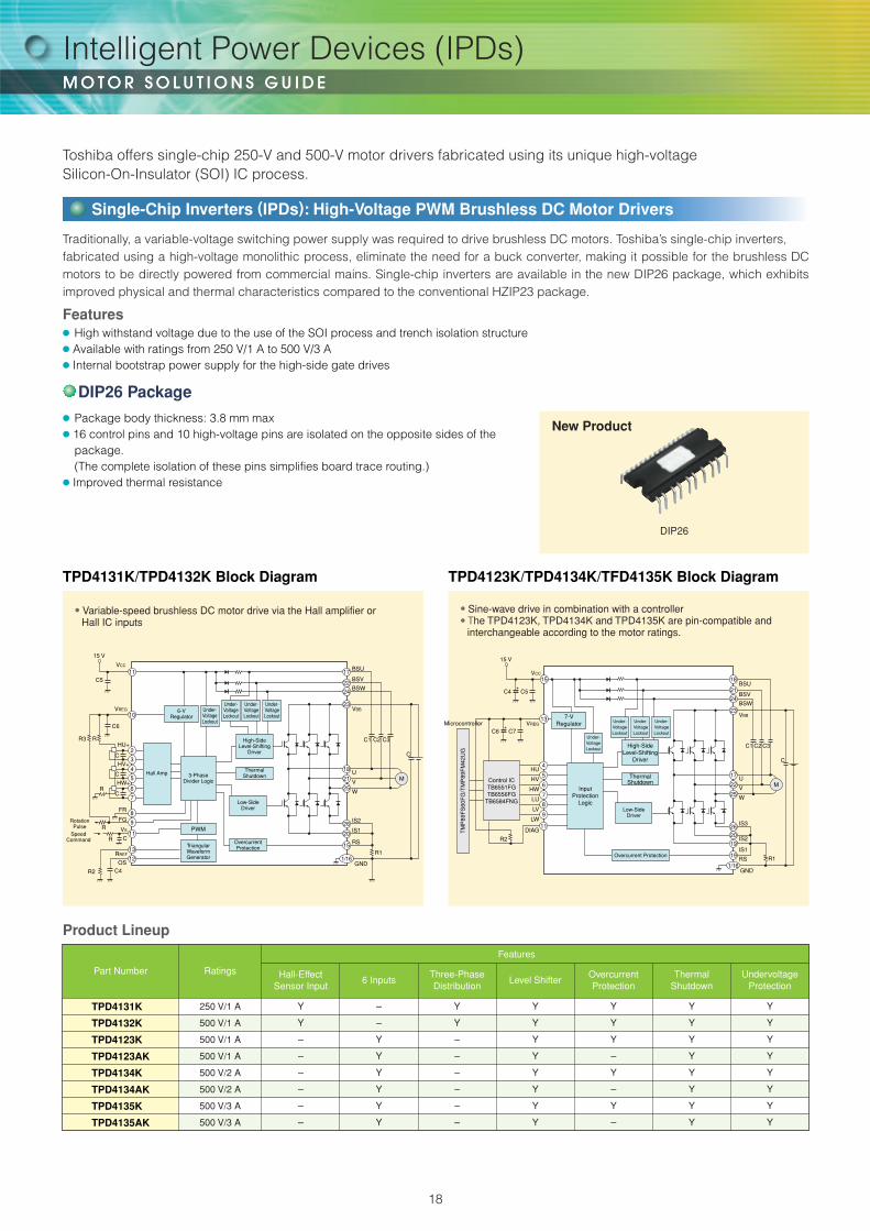
Traditionally, a variable-voltage switching power supply was required to drive brushless DC motors. Toshiba’s single-chip inverters,fabricated using a high-voltage monolithic process, eliminate the need for a buck converter, making it possible for the brushless DC motors to be directly powered from commercial mains. Single-chip inverters are available in the new DIP26 package, which exhibits improved physical and thermal characteristics compared to the conventional HZIP23 package.
New Product
DIP26
TPD4131K/TPD4132K Block Diagram TPD4123K/TPD4134K/TFD4135K Block Diagram
● Variable-speed brushless DC motor drive via the Hall amplifier or Hall IC inputs
● Sine-wave drive in combination with a controller● The TPD4123K, TPD4134K and TPD4135K are pin-compatible and
interchangeable according to the motor ratings.
● Package body thickness: 3.8 mm max● 16 control pins and 10 high-voltage pins are isolated on the opposite sides of the
package.(The complete isolation of these pins simplifies board trace routing.)
● Improved thermal resistance
6 Inputs
–
–
Y
Y
Y
Y
Y
Y
DIP26 Package
Toshiba offers single-chip 250-V and 500-V motor drivers fabricated using its unique high-voltage Silicon-On-Insulator (SOI) IC process.
Features● High withstand voltage due to the use of the SOI process and trench isolation structure● Available with ratings from 250 V/1 A to 500 V/3 A● Internal bootstrap power supply for the high-side gate drives
Intelligent Power Devices (IPDs)
18
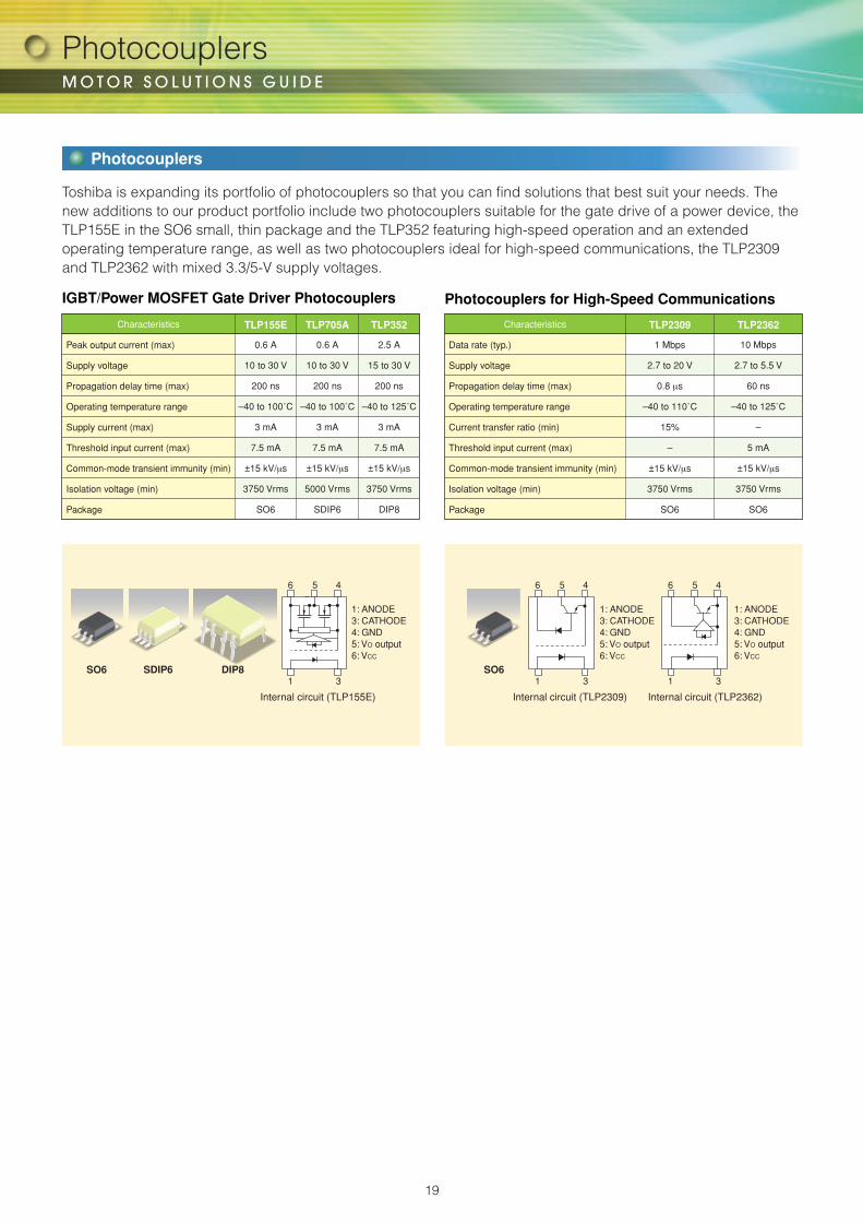
1 3
6 5 4 6 5 4
1 3
1: ANODE3: CATHODE4: GND5: VO output6: VCC
SDIP6SO6 DIP8
1: ANODE3: CATHODE4: GND5: VO output6: VCC
SO6
1: ANODE3: CATHODE4: GND5: VO output6: VCC
6 5 4
1 3
Internal circuit (TLP155E) Internal circuit (TLP2362)Internal circuit (TLP2309)
Photocouplers
IGBT/Power MOSFET Gate Driver Photocouplers Photocouplers for High-Speed Communications
Peak output current (max)
Supply voltage
Propagation delay time (max)
Operating temperature range
Supply current (max)
Threshold input current (max)
Common-mode transient immunity (min)
Isolation voltage (min)
Package
Characteristics
0.6 A
10 to 30 V
200 ns
–40 to 100˚C
3 mA
7.5 mA
±15 kV/μs
3750 Vrms
SO6
TLP155E
0.6 A
10 to 30 V
200 ns
–40 to 100˚C
3 mA
7.5 mA
±15 kV/μs
5000 Vrms
SDIP6
TLP705A
2.5 A
15 to 30 V
200 ns
–40 to 125˚C
3 mA
7.5 mA
±15 kV/μs
3750 Vrms
DIP8
TLP352
Data rate (typ.)
Supply voltage
Propagation delay time (max)
Operating temperature range
Current transfer ratio (min)
Threshold input current (max)
Common-mode transient immunity (min)
Isolation voltage (min)
Package
Characteristics
1 Mbps
2.7 to 20 V
0.8 μs
–40 to 110˚C
15%
–
±15 kV/μs
3750 Vrms
SO6
TLP2309
10 Mbps
2.7 to 5.5 V
60 ns
–40 to 125˚C
–
5 mA
±15 kV/μs
3750 Vrms
SO6
TLP2362
Toshiba is expanding its portfolio of photocouplers so that you can find solutions that best suit your needs. The new additions to our product portfolio include two photocouplers suitable for the gate drive of a power device, the TLP155E in the SO6 small, thin package and the TLP352 featuring high-speed operation and an extended operating temperature range, as well as two photocouplers ideal for high-speed communications, the TLP2309 and TLP2362 with mixed 3.3/5-V supply voltages.
Photocouplers
19

Website: http://www.semicon.toshiba.co.jp/eng
Semiconductor & Storage Products Company
SCE0020E
Motor S
olutions Guide
Previous edition: SCE0020D2011-9(1k)SO-DQ
2011
OVERSEAS SUBSIDIARIES AND AFFILIATES
Toshiba AmericaElectronic Components, Inc.
Toshiba Electronics do Brasil Ltda.
Toshiba Electronics Europe GmbH
Toshiba Electronics Asia (Singapore) Pte. Ltd.
Toshiba Electronics Service (Thailand) Co., Ltd.
Toshiba Electronics Trading (Malaysia) Sdn. Bhd.
Toshiba India Private Ltd.
Toshiba Electronics Asia, Ltd.
Toshiba Electronics (Shenzhen) Co.,Ltd
Toshiba Electronics (Shanghai) Co., Ltd.
Toshiba Electronics (Dalian) Co., Ltd.
Tsurong Xiamen Xiangyu Trading Co., Ltd.
Toshiba Electronics Korea Corporation
Toshiba Electronics Taiwan Corporation
2011-9
TOSHIBA ASSUMES NO LIABILITY FOR CUSTOMERS' PRODUCT DESIGN OR APPLICATIONS.
ABSENT A WRITTEN SIGNED AGREEMENT, EXCEPT AS PROVIDED IN THE RELEVANT TERMS AND CONDITIONS OF SALE FOR PRODUCT, AND TO THE MAXIMUM EXTENT ALLOWABLE BY LAW, TOSHIBA (1) ASSUMES NO LIABILITY WHATSOEVER, INCLUDING WITHOUT LIMITATION, INDIRECT, CONSEQUENTIAL, SPECIAL, OR INCIDENTAL DAMAGES OR LOSS, INCLUDING WITHOUT LIMITATION, LOSS OF PROFITS, LOSS OF OPPORTUNITIES, BUSINESS INTERRUPTION AND LOSS OF DATA, AND (2) DISCLAIMS ANY AND ALL EXPRESS OR IMPLIED WARRANTIES AND CONDITIONS RELATED TO SALE, USE OF PRODUCT, OR INFORMATION, INCLUDING WARRANTIES OR CONDITIONS OF MERCHANTABILITY, FITNESS FOR A PARTICULAR PURPOSE, ACCURACY OF INFORMATION, OR NONINFRINGEMENT.

Mouser Electronics
Authorized Distributor
Click to View Pricing, Inventory, Delivery & Lifecycle Information: Toshiba:
TB62208FTG(EL)