motor protection solutions brochure - reynoldsonline.com€¦ · detailed logs and control from...
TRANSCRIPT

Motor Protection Solutions
Bulletins 193, 592, 809S, 813S, 814S, 817S and 825-P

Voltage
Current
Temperature
Bimetallic Overload Relays
Bulletins 193-K, -T1
Features
• Overload protection trip class 10
• Phase loss sensitivity
• Ambient temperature compensation
for consistency
• 1 N.O. and 1 N.C. auxiliary contacts
Benefi ts
• Rated for DC and variable frequency drives
applications up to 400 Hz
• Stop Button for economic enclosure applications
• Visible trip indicator
• Optional remote reset solenoid and external
reset accessories
Advantages
• Easy mounting with Allen-Bradley® contactors
• Simple reset
Applications
• Conveyors
• Fans
• Pumps
• VFD-controlled motors
Protection, Warning, Diagnostics and Control
Motor Protection Solution
MachineAlert™ Monitoring Relays
Bulletins 809S, 813S, 814S, 817S
Features
• Current monitoring relay
• Voltage monitoring relay
• Active power (kW) monitoring relay
• Power factor (cosθ) monitoring relay
• Thermistor monitoring relay
Benefi ts
• Programmable latching or inhibit at set level
• Adjustable time delay settings
• Three-phase devices are powered by
the measuring circuit
• LED indication for relay, alarm and power supply
• Global application with CE and UL approvals
Advantages
• Expandable, supplemental protection
Applications
• Blowers • Conveyors
• Compressors • Cutting & drilling machines
• Fans • Mixers
• Pumps • VFD-controlled motors
2
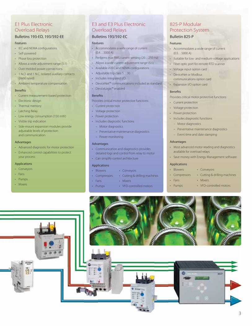
E1 Plus Electronic Overload Relays
Bulletins 193-ED, 193/592-EE
Features
• IEC and NEMA confi gurations
• Self-powered
• Phase loss protection
• Allows a wide adjustment range (5:1)
• Over-molded power connections
• 1 N.O. and 1 N.C. isolated auxiliary contacts
(B600 rated)
• Ambient temperature compensation
Benefi ts
• Current measurement-based protection
• Electronic design
• Thermal memory
• Latching Relay
• Low energy consumption (150 mW)
• Visible trip indication
• Side-mount expansion modules provide
adjustable levels of protection
and communication
Advantages
• Advanced diagnostic for motor protection
• Enhanced control capabilities to protect
your process
Applications
• Conveyors
• Fans
• Pumps
• Mixers
E3 and E3 Plus Electronic Overload Relays
Bulletins 193/592-EC
Features
• Accommodates a wide range of current
(0.4…5000 A)
• Performs true RMS current sensing (20…250 Hz)
• Allows a wide current adjustment range (5:1)
• Available in IEC and NEMA confi gurations
• Adjustable trip class 5…30
• Includes integrated I/O
• DeviceNet™ communications included as standard
• DeviceLogix™ enabled
Benefi ts
Provides critical motor protective functions
• Current protection
• Voltage protection
• Power protection
• Includes diagnostic functions
– Motor diagnostics
– Preventative maintenance diagnostics
– Power monitoring
Advantages
• Communication and diagnostics provides
detailed logs and control from relay to motor
• Can simplify control architecture
Applications
• Blowers • Conveyors
• Compressors • Cutting & drilling machines
• Fans • Mixers
• Pumps • VFD-controlled motors
825-P Modular Protection System
Bulletin 825-P
Features
• Accommodates a wide range of current
(0.5…5000 A)
• Suitable for low- and medium-voltage applications
• Fiber optic port for remote RTD scanner
• Voltage input option card
• DeviceNet or Modbus
communications option card
• Expansion I/O option card
Benefi ts
Provides critical motor protective functions
• Current protection
• Voltage protection
• Power protection
• Includes diagnostic functions
– Motor diagnostics
– Preventative maintenance diagnostics
– Event time and date stamping
Advantages
• Most advanced motor reading and diagnostics
available for overload relays
• Save money with Energy Management software
Applications
• Blowers • Conveyors
• Compressors • Cutting & drilling machines
• Fans • Mixers
• Pumps • VFD-controlled motors
3

E1 Plus Overload Relay
The Allen-Bradley Bulletins 193 and 592 E1 Plus Overload Relays are the industry’s fi rst
modular self-powered devices. The E1 Plus solid-state design provides thermal overload
and phase loss protection while off ering application fl exibility through a wide 5:1
adjustment range.
The direct mounting and Pass-Thru style relays are off ered in two models. The ED model
provides fi xed protection while the EE model provides selectable and expandable
protection, and is available in single-phase and three-phase applications.
E1 Plus IEC
Allows maintenance personnel to remotely reset the E1 Plus Overload Relays while
keeping the enclosure door closed
E1 Plus Pass-Thru Style
The E1 Plus is also available in a Pass-Thru style for applications using a Bulletin 100-K
Mini Contactor, external current transformers, or non Allen-Bradley contactors. The E1 Plus
Pass-Thru includes an integrated DIN Rail mount and has the footprint of a traditional
bi-metal overload relay.
• Available in ED and EE models
• 0.1…27 A current range
• Compact size
• Integrated DIN Rail and panel mount
E1 Plus ED Model
• IEC confi guration
• 0.1…45 A current range
• Fixed motor protection (Class 10)
• Manual reset
E1 Plus EE Model
• NEMA and IEC confi gurations
• 0.1…800 A current range
• Selectable motor protection
(Class 10, 15, 20 or 30)
• Selectable manual/auto-manual reset
• Single- and three-phase devices
• Expandable with optional protection
and communication modules
E1 PlusNEMA
E1 Plus with Panel Mount Adapter
111 mm
58 mm
E1 PlusPass-Thru
Remote Reset Capable
E1 P
E1 Pl
4

E1 Plus Electronic Overload Relay EtherNet/IP Communication Module
Advantages
• Compact
– Direct mounting to the
left side of the overload relays
adds only 18 mm of width
• Simplifi ed Control
– The side-mount modules electronically interface with the
overload relay so that all control circuit connections are made
at the E1 Plus overload relay terminals
• Flexibility
– The modular design allows expanded functionality in only
those applications where it is required
E1 Plus Protection Modules
The E1 Plus Protection Side-Mount Modules
provide adjustable levels of protection,
tailored to your application.
• Ground fault protection
• Jam protection
• PTC thermistor monitoring
• Remote Reset Module*
MachineAlert™
Expand your motor protection with
the MachineAlert family of monitoring
relays that are easily added and applied
to your motor control circuits.
Bulletin 813S Voltage Monitoring Relays
guard against the damaging eff ects
of phase loss, under and over voltage,
phase imbalance, and phase reversal.
Provides supplemental protection in conjunction with the
Bimetallic and Electronic Overload Relays
The optional remote indication display increases your
motor maintenance productivity as maintenance
personnel can view the status and reset an E1 Plus
from a closed electrical enclosure.
• Overload trip
• Overload warning
• Side-mount module trip
• E1 Plus status
E1 Plus Communication Modules
The E1 Plus Communication Side-Mount Modules
provide a cost-eff ective, seamless deployment of
motor starters with your control architecture.
• DeviceNet
• EtherNet/IP™
• PROFIBUS
Advantages
• Includes integrated I/O
– Provides convenient local termination of
motor-related inputs (2) and outputs (1),
simplifying the control architecture
• Provides operational and diagnostic data
– Average motor current
– Percentage of thermal capacity usage
– Device status
– Trip and warning identifi cation
– Trip history (5 previous trips)
• Expands protective functions
– Overload warning
– Jam protection
– Underload warning
813S Voltage Monitoring Relay
193-ERID (Front)1
193-ERID (Back)
* No protection provided.
5
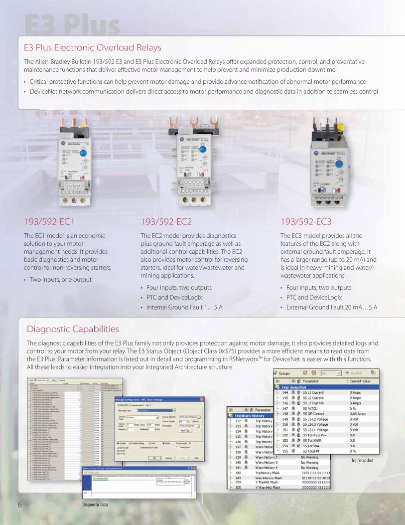
E3 Plus Electronic Overload Relays
The Allen-Bradley Bulletin 193/592 E3 and E3 Plus Electronic Overload Relays off er expanded protection, control, and preventative
maintenance functions that deliver eff ective motor management to help prevent and minimize production downtime.
• Critical protective functions can help prevent motor damage and provide advance notifi cation of abnormal motor performance
• DeviceNet network communication delivers direct access to motor performance and diagnostic data in addition to seamless control
Diagnostic Capabilities
The diagnostic capabilities of the E3 Plus family not only provides protection against motor damage, it also provides detailed logs and
control to your motor from your relay. The E3 Status Object (Object Class 0x375) provides a more effi cient means to read data from
the E3 Plus. Parameter information is listed out in detail and programming in RSNetworx™ for DeviceNet is easier with this function.
All these leads to easier integration into your Integrated Architecture structure.
Trip Snapshot
193/592-EC1
The EC1 model is an economic
solution to your motor
management needs. It provides
basic diagnostics and motor
control for non-reversing starters.
• Two inputs, one output
193/592-EC2
The EC2 model provides diagnostics
plus ground fault amperage as well as
additional control capabilities. The EC2
also provides motor control for reversing
starters. Ideal for water/wastewater and
mining applications.
• Four inputs, two outputs
• PTC and DeviceLogix
• Internal Ground Fault 1…5 A
193/592-EC3
The EC3 model provides all the
features of the EC2 along with
external ground fault amperage. It
has a larger range (up to 20 mA) and
is ideal in heavy mining and water/
wastewater applications.
• Four inputs, two outputs
• PTC and DeviceLogix
• External Ground Fault 20 mA…5 A
Diagnostic Data6

• DeviceLogix component technology helps increase the control possibilities with function block programs that operate at the device
level. DeviceLogix allows for an organized shutdown process over the network to protect your motor during unplanned power loss
• Integrated I/O provides convenient local termination of motor-related inputs and outputs, simplifying the control architecture
• Preventative maintenance functions can provide notifi cation that motor maintenance is due, based on hours of operation
and/or the number of starts
RSEnergyMetrix Software
RSEnergyMetrix Software
The E3 Plus can be included in your energy
management system.
• Helps identify which motors contribute to the
monthly peak demand and power factor line items
on a utility bill
• Helps to verify energy reduction initiatives
• Increase your energy accountability
to reduce overall cost
RSSE M t i S ftt
193-EC4
The EC4 model is a current monitoring
relay for three independent channels.
The EC4 is ideal in heat tracing
applications and lighting loads.
• Four inputs, two outputs
• DeviceLogix
• External Ground Fault 20 mA…5 A
Current Elements
• Phase currents
• Average current
• % Motor load
• Ground Fault Current
Voltage Elements
• Line-line voltages
• Average line-line voltage
• Line-neutral voltages
• Voltage imbalance
• System frequency
Power Elements
• Real power (kW)
• Reactive power (kVAR)
• Power factor
• Phase angle
• Energy
193/592-EC5
The EC5 model features voltage
protection and energy monitoring.
• Current and voltage protection
• Enhanced power monitoring and
diagnostic capabilities
• Six inputs, two outputs
• DeviceLogix and Voltage
• External Ground Fault 20 mA…5 A
EtherNet/IP
Communications Auxiliary
• For use with E3 Plus
Electronic Overload Relays
• Allows DeviceNet-based users to
seamlessly communicate on an
EtherNet/IP network
• No additional software is required
7

825-P Modular Protection System
The combined off ering of DeviceLogix communication and RTD heat sensing
diagnostics give you the full story behind how your motor is functioning. A
more advanced thermal overload algorithm allows you to get a more accurate
reading of your motor. The monitoring is date and time stamped to assist with
troubleshooting as well as avoiding future issues and downtime.
Current Elements
• Phase currents
• Average current
• % Motor load
• Ground Fault Current
Voltage Elements
• Line-line voltages
• Average line-line
voltage
• Line-neutral voltages
• Voltage imbalance
• System frequency
Power Elements
• Real power (kW)
• Reactive power
(kVAR)
• Power factor
• Phase angle
• Energy
Thermal Elements
• % Thermal
capacity utilization
• RTD values
Communication
Elements
• DeviceNet
communication card
with DeviceLogix
technology
• Modbus RTU
communication card
Full Function Metering
The 825-P Option Cards
Communication Cards
• DeviceNet with DeviceLogix technology provides additional inputs and outputs to
quickly and effi ciently transfer your diagnostic motor information across a network
• Modbus RTU card provides voltage input and power protection
via RSEnergy Metrix for power monitoring diagnostics
Voltage Input
• Input terminations for VA, VB, VC and VN
• Enables voltage and power measurement and related protection functions
• Accommodates potential transformers for levels exceeding 250V AC
I/O Expansion
• Three confi gurable inputs
• Four auxiliary relay outputs
• 4…20 mA isolated analog output
The base 825-P unit and converter
module are basic requirements to
start utilizing monitoring capability.
This component of the 825-P
tracks Ground Fault Current.
The RTD scanner provides thermal
monitoring (up to 12 positions) in the
motor. These diagnostics are applied to
the algorithm for motor protection.
Base Unit
Converter Module
RTD Scanner
Core Balance Current Transformer
Option Cards
ConConvverter Module
RTD Scanner
8

To address energy usage concerns, the 825-P provides you
with the following energy diagnostic information:
• Real energy (MWh)
• Reactive energy (MVARh)
• Apparent energy (MVAh)
This information can be used to reduce overall energy
usage, saving you valuable dollars in utility charges.
The 825-P Modular Protection System is a key component
to energy accountability.
MPS Explorer Software
This complimentary, optional software provides access to settings and
data on the 825-P Modular Protection Systems (MPS) for motors.
• Intuitive interface for programming and adjusting
• User-friendly, menu-driven confi guration
• Effi cient information fl ow from module to PC
• Settings can be modifi ed on or offl ine
• Real-time metering data monitoring
• Easy access to diagnostic information
• Export data collection for use or manipulation into
popular applications such as Microsoft® Excel®
RSEnergyMetrix Software
Confi guration
Data Trending/Monitoring
9

10
Bimetallic Overload Relays
The Bulletin 193-K/T1 bimetallic overload relays off er basic motor
protection at an economic price.
• Overload protection trip class 10
• 1 N.O. and 1 N.C. Auxiliary Contact
• Manual/automatic reset mode selectable
• Ambient temperature compensated for consistency (20…60 ˚C)
• The diff erential mechanism off ers high sensitivity to phase loss
• Rated for DC and variable frequency drives applications up to 400 Hz
• Designed for Bulletin 100-K and 100-C contactor mounting
• Remote reset capable
Applications
• Conveyors
• Fans
• Pumps
• VFD-controlled motors
MachineAlert Monitoring Relays
Panel builders, electrical controls designers and OEMs are
looking for cost eff ective ways to protect their electrical
equipment investment.
These monitoring relays provide supplemental electronic
motor protection including:
• Dedicated function motor protection relays
– Voltage Monitoring
Guards against the damaging eff ects of phase loss,
under and overvoltage, phase imbalance, phase
reversal, and voltage quality of incoming power line
– Current Monitoring
Provides under and overcurrent detection
– Thermistor Monitoring
Protects equipment from overtemperature conditions
– Active Power (kw)
Monitors for under and over active power as well as
power direction
– Power Factor (PF)
Monitors for under and over power factor detection
Applications
• Protects motors against single phasing in elevator
applications or in air conditioning systems
• Detects incorrect phase sequence to keep the motor
starter from starting
• Detects no-load conditions indicating absence of water in
water lubricated pumps
Provides supplemental protection in
conjunction with the Bimetallic and
Electronic Overload Relays
817S Thermistor 814SPower Factor (PF)Active Power (kw)
809S Current 813S Power
11
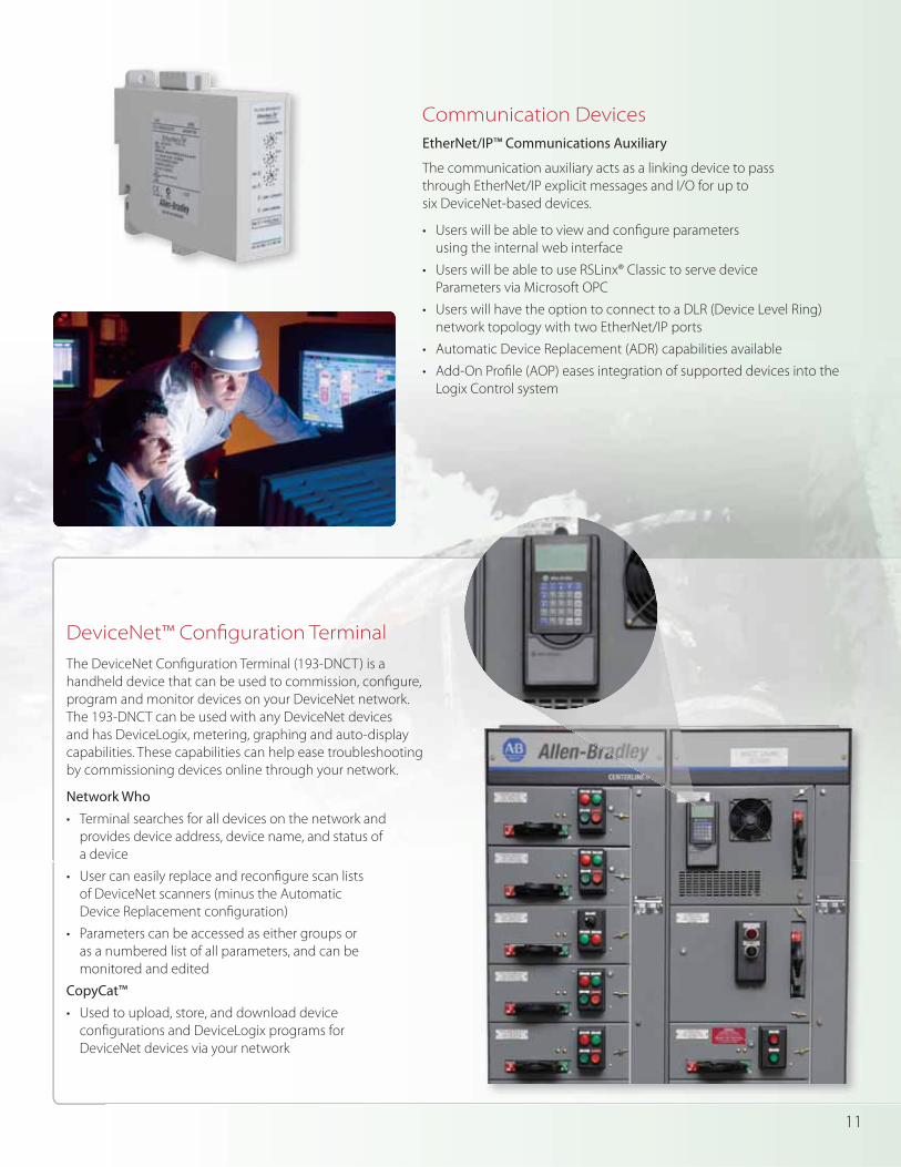
DeviceNet™ Confi guration Terminal
The DeviceNet Confi guration Terminal (193-DNCT) is a
handheld device that can be used to commission, confi gure,
program and monitor devices on your DeviceNet network.
The 193-DNCT can be used with any DeviceNet devices
and has DeviceLogix, metering, graphing and auto-display
capabilities. These capabilities can help ease troubleshooting
by commissioning devices online through your network.
Network Who
• Terminal searches for all devices on the network and
provides device address, device name, and status of
a device
• User can easily replace and reconfi gure scan lists
of DeviceNet scanners (minus the Automatic
Device Replacement confi guration)
• Parameters can be accessed as either groups or
as a numbered list of all parameters, and can be
monitored and edited
CopyCat™
• Used to upload, store, and download device
confi gurations and DeviceLogix programs for
DeviceNet devices via your network
Communication Devices
EtherNet/IP™ Communications Auxiliary
The communication auxiliary acts as a linking device to pass
through EtherNet/IP explicit messages and I/O for up to
six DeviceNet-based devices.
• Users will be able to view and confi gure parameters
using the internal web interface
• Users will be able to use RSLinx® Classic to serve device
Parameters via Microsoft OPC
• Users will have the option to connect to a DLR (Device Level Ring)
network topology with two EtherNet/IP ports
• Automatic Device Replacement (ADR) capabilities available
• Add-On Profi le (AOP) eases integration of supported devices into the
Logix Control system

Publication 193-BR029A-EN-P – July 2011 Copyright ©2011 Rockwell Automation, Inc. All Rights Reserved. Printed in USA.
Allen-Bradley, DeviceLogix, Integrated Architecture, MachineAlert, RSEnergyMetrix, RSLinx and RSNetWorx for DeviceNet are trademarks of Rockwell Automation Inc. DeviceNet and EtherNet/IP are
trademarks of the Open DeviceNet Vendor Association. Trademarks not belonging to Rockwell Automation are the properties of their respective companies.
Rockwell Automation off ers a breadth of quality Allen-Bradley® components to fi t your specifi c needs. In order to assist you with your component selection, we off er a variety of confi guration and selection tools.
Local DistributorCall 1.800.223.3354 to contact your local Distributor today.http://www.rockwellautomation.com/distributor/
On-Line Product DirectoryOur extensive product portfolio is designed to improve your processes through every stage of your manufacturing cycle.http://www.rockwellautomation.com/products/
Product Selection Toolbox guration tools assist you in choosing and
applying our products.http://www.rockwellautomation.com/en/e-tools/
Catalogs nd an extensive selection of essential Allen-Bradley component products.
http://www.ab.com/catalogs/
193-DNENCATR
MS
NS
Link 1 (REAR)
NS
Link 1 (FRONT)
0 X1008
6 4
2
0 X108
6 4
2
0 X18
6 4
2
EtherNet IP
193-ETN
OUT
IN2
IN1
MS
NS
LINK
E1 Plus193-EDN
NETWORK
OUT A
IN 1
IN 2
TEST RESET
TRIPSTATUS
TRIP
E1 Plus
TEST RESET
TRIPSTATUS
TRIP
FORCE
RUN SD OKFORCE
Logix5575 EtherNet/IP™
Workstation
ControLogix
E1 Plus with -EDN
E3 PLUSEC5 Model
E1 PLUS with -ETN
E3 PLUS
E3 PLUS
DNCT 825-P
825-P
DeviceNetStarter Auxiliary
DeviceNetStarter Auxiliary
EtherNet/IPCommunications
Auxiliary
DeviceNet
EtherNet/IP
Adding Motor Protection to Integrated Architecture
Leading to easier
integration into your
Integrated Architecture
structure