motor monitoring services - skf so as to include the power cable in the test circuit. however, tests...
TRANSCRIPT

Early identiication of potential electric motor failures ensures the reliability of critical machinery
Motor monitoring services

Why test electric motors?
Electrical services provided:
• Static electric motor and
generator analysis
• Dynamic electric motor analysis
• Motor current signature analysis
As production requirements drive the demand for less downtime, higher output from machinery, and
lower maintenance and repair costs, monitoring the condition of equipment is becoming increasingly vital
for maintenance engineers. They would prefer to plan shutdowns and maintenance programmes based
upon equipment needs and condition, and to be aware of any potential problems that may lead to an
unexpected breakdown. Therefore, they require maintenance tools which can provide a comprehensive
condition assessment, and early prediction of faults and developing problems. Emphasis is now being
placed on predictive maintenance where problems can be identiied well in advance of a failure.
The use of a condition monitoring approach enables the early detection of a wide variety of faults, allowing
the scheduling of corrective maintenance at a convenient time. A variety of monitoring techniques exist,
with vibration analysis being the most widely used.
SKF is typically known as a provider of mechanically-related condition monitoring products and services.
However, with the acquisition of Baker Instruments it enables SKF to introduce a range of electrical
services that complete its offering in terms of rotating machinery performance and condition monitoring.
This ensures ownership of machinery problems until resolution, with no separation between electrical
and mechanical issues.

Static motor analysis
Reliable operation of electrical machines depends largely on
the integrity of their winding’s insulation. Failure can incur
high repair costs even before considering the loss to
production. Over time, the insulation system of a motor or
generator deteriorates through thermal, electrical,
mechanical and chemical stresses; and periodic assessment
of the insulation condition can determine a range of insulation
problems at an early stage. This enables timely remedial
action and can prevent the occurrence of failure, and
uncontrolled outage of equipment.
SKF static testing provides in-depth analysis of the stator’s
winding circuit and insulation, through a range of tests:
• Winding resistance to check for balance between phases
• Insulation resistance (Megohm)
• PI and DC step voltage testing to assess the ground wall
insulation
• Surge testing to check for phase to phase and inter-turn
defects within the windings
Site testing is typically performed at the motor control
cabinet, so as to include the power cable in the test circuit.
However, tests can also be made at the motor terminal box.
SKF static analysers perform the tests in speciic order,
starting with the low-voltage winding resistance test,
insulation resistance, polarization index, DC step voltage,
and inally the surge test.
The SKF Static Motor Analyzer Baker AWA combines multi-
function insulation testing capabilities and computer control
into a ield portable instrument. Test parameters are pre-
programmed to avoid operator error. The pass/fail limits,
which can be set to international standards or agreed by site,
eliminate all guesswork and provide guidance when assessing
motor and insulation condition.
Should a test fail, the unit will stop the testing sequence.
Testing will only resume once the cause of the failure has
been investigated and corrected.
Tests up to 40 kV can be completed, covering both low voltage
and high voltage machines. This equipment also provides
computer-generated reports of
the tests performed, and
automatically trends the
values over time.
Winding resistance
This is a low voltage test (12VDC or less), using 4-wire kelvin
leads for accuracy. It measures and compares the resistance
of the three phases and is capable of measuring down to one
milliohm. This will allow the detection of loose or corroded
connections, short and open circuits. It can also indicate
incorrectly wound windings, when compared to previous
values. The percentage unbalance can be trended over time
to detect developing faults. The test unit will correct the
measured resistance value to 20 °C, which allows the
readings to be reliably trended over time.
SKF Static Motor Analyzer
Baker AWA 12 kV
Stock inventory motors
Stock motors are typically held to allow quick replacement on
critical machines. These motors often sit in storage for years,
and unless tested regularly, their condition is unknown and
cannot be relied upon.
Static testing should be performed to verify condition prior to
installation, but ideally also on an annual basis.
Insulation resistance (or the Megohm test)
The insulation resistance (IR) test is an accurate
measurement of the ground wall insulation resistance. The
test consists of applying a DC voltage according to industry
standards and measuring the leakage current. The leakage
current measurement is taken 60 seconds after the test
voltage is reached to allow the charging current to dissipate.
The IR value is calculated using Ohm’s law. The IR value is
automatically temperature corrected to 40 °C. Trending non-
corrected IR values over time will give skewed results due to
the differences in winding temperature when the tests were
performed. The test can identify:
• Damaged and burnt slot liner insulation or enamel wire
• Contamination - carbon dust, water or other contaminates
• Shorted windings to ground
• Poor cable insulation
3

Polarisation index
The polarisation index (PI) test is an extension of the IR test
and is performed to quantitatively measure the ability of the
ground wall insulation to polarise. When an insulator
polarises, the electric dipoles distributed in the insulator align
themselves with an applied electric ield. As the molecules
polarise, a ‘polarisation current’ (also called absorption
current) is developed that adds to the insulation leakage
current. The PI test is performed at the same voltage as the
IR test and takes 10 minutes to complete.
In general, insulators that are in good condition will show a
high polarisation index while insulators that are damaged will
not. Low PI values can indicate moisture or contamination,
and also brittle insulation.
DC step voltage test
The DC step voltage test is typically performed at twice the
motor’s operating voltage plus 1,000 volts. The test is used to
verify that the insulation to earth is able to withstand the high
voltage transients that motors see on start-up/shutdown.
The voltage is gradually increased over ive steps until the
target voltage is reached, with each voltage step held for one
minute. The leakage current at each voltage step is measured
and the current proile over the ive steps examined. Whilst
clean and dry insulation shows very linear current increase,
non-linear increase would indicate contamination, moisture
or ground wall/cable insulation damage.
Surge test
Studies have shown that 80% of electrical failures in AC
motors start as inter-turn insulation weakness. These turn-
to-turn faults typically progress and develop into an earth
fault, but often are not detected prior to the motor failing.
Paschen’s law states that in order for voltage to arc between
two conductors, a potential difference of at least 335 volts is
required. The required voltage will vary depending on the
insulation weakness and the air gap size. During the IR, PI
and DC step voltage tests, all the turns of the winding are
raised to the same voltage potential, hence these tests are
not capable of detecting turn to turn weakness.
The surge test works by injecting high voltage impulses into
one phase at a time, creating a turn-to-turn potential
difference. By testing at industry standard levels, weak
turn-to-turn insulation can be detected in advance,
allowing time to plan the required maintenance work. The
surge test simulates the high voltage switching surges that
motors see during start-up and shut-down.
Linear proile
Normal waveforms
Failed waveforms
Normal pulse to pulse graph
Failed pulse to pulse graphNon-linear proile
4

Dynamic electric motor analysis
Generally, motor operation and performance is a response to
power supply quality and load variations, both of which can be
captured by measuring voltages and currents during normal
motor operation.
SKF dynamic motor analysis equipment is used for the
measurement of these voltages and currents. The technique
uses clamp-on current transformers and voltage clips
temporarily connected in the motor control cabinet (no access
is required to the motor terminal box).
SKF Surveyor software is used to analyse the motor voltages
and currents under normal operating condition. It then
calculates further parameters including voltage and current
harmonics, power, motor speed, torque, spectra, etc.
Dynamic testing can be applied to both LV and HV motors,
and allows a comprehensive range of variables to be
monitored and used to assess the power supply quality, motor
condition and performance, rotor cage condition, rotor–stator
air gap eccentricity as well as load performance and
mechanical inluences.
Test results – good, caution or warning, are then presented
using a trafic light system as shown below.
The test engineer can drill down to view further data and
results to make an accurate assessment of the entire motor
driven system.
The EXP4000 test unit utilises multiple tests to determine the
power condition, motor health, load and energy proile for the
motor using the following test domains:
• Power quality: Identiies over and under voltage
conditions, voltage distortions as well as voltage
unbalances.
• Machine performance: Assesses the overall motor
performance with regards to thermal overheating based
on load and power quality, and calculates a NEMA derating
factor that relects the true motor operating conditions.
• Current: Problems such as over-loading, poor connect-
ions, misconnections, iron saturation and mis-wound
motors are dificult to detect without the right equipment.
The EXP4000 evaluates current and current unbalances to
assess the overall electrical condition of the motor/
machine system.
• Torque: Transient conditions can easily over-stress a
machine system, but can be very dificult to identify and
assess. SKF’s innovative torque analysis capabilities within
the EXP4000 provide the means to ind torque-related
problems. The torque time and spectrum signatures are
used to diagnose mechanical problems, and to clearly
identify transient conditions. Users can accurately identify
issues including cavitation, bearing problems, mechanical
imbalances, eccentricities, misaligned shafts and more.
• VFD: VFDs/Inverter drives pose a unique set of challenges
for maintenance professionals. The EXP4000 has the
means to monitor and effectively troubleshoot this
increasingly popular motor drive technique. The EXP4000
displays the V/Hz relationship with respect to time. This
helps with setup and commissioning, and improves the
ability to troubleshoot VFD issues.
• Eficiency: The EXP4000 identiies poorly-performing
motors with accurate assessments of operating eficiency
within their current applications. This is especially valuable
for motor replacement decision support.
SKF Dynamic Motor Analyzer EXP4000
Typical AC motor test result page Typical torque ripple display showing cavitation
5
• Transient analysis: Typically used to monitor the start-up
phase of the motor, measuring and recording the voltage
and current against time, plus the torque proile against
time.
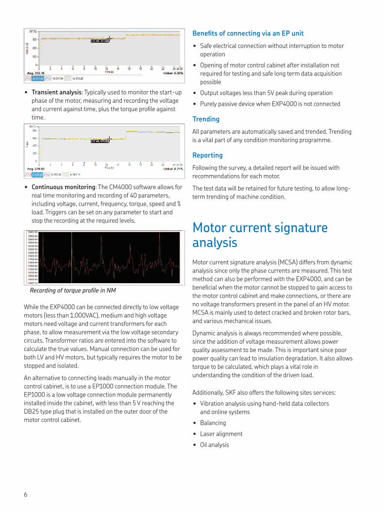
• Continuous monitoring: The CM4000 software allows for
real time monitoring and recording of 40 parameters,
including voltage, current, frequency, torque, speed and %
load. Triggers can be set on any parameter to start and
stop the recording at the required levels.
While the EXP4000 can be connected directly to low voltage
motors (less than 1,000VAC), medium and high voltage
motors need voltage and current transformers for each
phase, to allow measurement via the low voltage secondary
circuits. Transformer ratios are entered into the software to
calculate the true values. Manual connection can be used for
both LV and HV motors, but typically requires the motor to be
stopped and isolated.
An alternative to connecting leads manually in the motor
control cabinet, is to use a EP1000 connection module. The
EP1000 is a low voltage connection module permanently
installed inside the cabinet, with less than 5 V reaching the
DB25 type plug that is installed on the outer door of the
motor control cabinet.
Motor current signature analysis
Motor current signature analysis (MCSA) differs from dynamic
analysis since only the phase currents are measured. This test
method can also be performed with the EXP4000, and can be
beneicial when the motor cannot be stopped to gain access to
the motor control cabinet and make connections, or there are
no voltage transformers present in the panel of an HV motor.
MCSA is mainly used to detect cracked and broken rotor bars,
and various mechanical issues.
Dynamic analysis is always recommended where possible,
since the addition of voltage measurement allows power
quality assessment to be made. This is important since poor
power quality can lead to insulation degradation. It also allows
torque to be calculated, which plays a vital role in
understanding the condition of the driven load.
Beneits of connecting via an EP unit
• Safe electrical connection without interruption to motor
operation
• Opening of motor control cabinet after installation not
required for testing and safe long term data acquisition
possible
• Output voltages less than 5V peak during operation
• Purely passive device when EXP4000 is not connected
Trending
All parameters are automatically saved and trended. Trending
is a vital part of any condition monitoring programme.
Reporting
Following the survey, a detailed report will be issued with
recommendations for each motor.
The test data will be retained for future testing, to allow long-
term trending of machine condition.
Additionally, SKF also offers the following sites services:
• Vibration analysis using hand-held data collectors
and online systems
• Balancing
• Laser alignment
• Oil analysis
Recording of torque proile in NM
6

TKTI SERIES
DETECTS UP TO
600°C
Infrared thermography
Infrared thermography is a non-invasive predictive
maintenance tool used for numerous applications including
the inspection of electrical switchgear and control systems,
mechanical systems and process systems.
Objects radiate heat as infra-red radiation, which the human
eye is unable to detect. The SKF Thermal Camera TKTI series
can measure and store this information allowing a skilled
operator to identify a wide range of problems.
Infrared thermography has the added advantage of being a
non-invasive diagnostic tool. This means that many
operational defects can be determined without altering the
operation of the machine or equipment, enabling condition to
be determined whilst in operation.
SKF operate the latest generation of thermographic cameras,
and have specialist engineers able to provide expert services
for the analysis of heat generating defects for various
applications. SKF can provide a comprehensive backup service
ensuring we deliver expertise and recommendations on
repair modiications or root cause investigations to improve
the maintenance and operation of your asset.
Typical defects detected:
• HV and LV switchgear
• Electrical distribution boards
• Electrical control panels
• Transformers
• Mechanical wear
• Misalignment
• Vessel content levels
• Pipe work blockages
• Valve operation
Remote dynamic monitoring service
As an alternative to route-based dynamic testing, SKF are
also able to utilise the SKF Online Motor Analysis System
NetEP. The NetEP is capable of monitoring up to 32 motors,
24 hours a day, 7 days a week, with data being sent directly to
SKF for analysis.
This is particularly interesting for motors in hazardous areas,
or for use on offshore installations, where travelling to site is
expensive and time consuming.
Rotor bar damage/cracked bars displaced from the SC ring
7

skf.co.uk
© SKF Group 2016
The contents of this publication are the copyright of the publisher and may not be reproduced (even extracts) unless prior written permission is granted. Every care has been taken to ensure the accuracy of the information contained in this publication but no liability can be accepted for any loss or damage whether direct, indirect or consequential arising out of the use of the information contained herein.
PUB CM/P2 16913 EN.UK · October 2016
Certain image(s) used under license from Shutterstock.com
SKF (U.K.) Limited
Wellheads Road, Farburn Industrial Estate,
Dyce, Aberdeen, AB21 7HG
T: 01224 723321