motor feedback systems for electric drives - … stegmann/motor-feedback... · motor feedback...
TRANSCRIPT

Motor Feedback Systems for Electric Drives
Maximum performance for all applications
I n D u S t r y G u I D E
www.hvssystem.com
Siège social :2 rue René Laennec51500 TaissyFrance
Contact : [email protected]
Tél : 0326824929Fax : 0326851908
Distribué par :
2 S I c k | S t E G M a n n
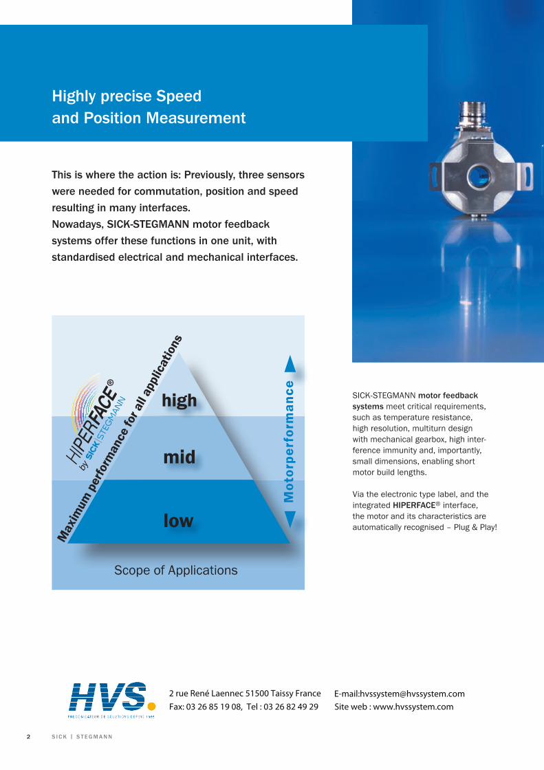
Highly precise Speed and Position Measurement
this is where the action is: Previously, three sensors were needed for commutation, position and speed resulting in many interfaces. nowadays, SIck-StEGMann motor feedback systems offer these functions in one unit, with standardised electrical and mechanical interfaces.
Scope of Applications
low
mid
high
Mot
orpe
rfor
man
ce
Max
imum
per
form
ance
for a
ll ap
plic
atio
ns
SICK-STEGMANN motor feedback systems meet critical requirements, such as temperature resistance, high resolution, multiturn design with mechanical gearbox, high inter-ference immunity and, importantly, small dimensions, enabling short motor build lengths.
Via the electronic type label, and the integrated HIPErFacE® interface, the motor and its characteristics are automatically recognised – Plug & Play!
2 rue René Laennec 51500 Taissy France Fax: 03 26 85 19 08, Tel : 03 26 82 49 29
E-mail:[email protected] web : www.hvssystem.com

2 S I c k | S t E G M a n n
Incremental Encoder for asynchronous motors number of lines up to 65,536 • VFS60 Dicoder® for synchronous motorsnumber of lines up to 4,096 and up to 32 pole pairs • CKS36 • CNS50 Sincos® for synchronous motors with HIPErFacE® Interface • SEK/SEL37up to 1,024 sine/cosine periods • SEK/SEL52 • SKS/SKM36 • SRS/SRM50 • SCK/SCL25-53 • SRS/SRM64 StanD aLOnE versionswith HIPErFacE® Interface • SKS/SKM36 up to 1,024 sine/cosine periods • SRS/SRM50 Length measuring systems and Distance Sensorswith HIPErFacE® Interface • TTK70 • L230measuring range up to 300 m • DME4000/DME5000
O V E r V I E W M O t O r F E E D b a c k S y S t E M S
M O t O r F E E D b a c k S y S t E M S 3

4 S I c k | S t E G M a n n
the robust solutionfor rough ambient conditions
V F S 6 0 V F S 6 0 with insulated hollow shaft clamping
• Through hollow shaft• Cable outlet axial/radial• Protection up to IP65• Electrical interfaces ttL and HtL
number of lines up to 65,536
Motor Feedback Systems
number of lines up to 65,536
Motor Feedback Systems
• Blind or through hollow shaft• Cable outlet axial/radial• Protection up to IP65• Electrical interfaces ttL and HtL
For detailed information see www.sick.com
Incremental EncodersVFS60
technical data
Hollow shaft diameter
Blind hollow shaft 8, 10, 12, 14 or 15 mm as –
well as 3/8'' 1/2'' and 5/8"
Through hollow shaft 10, 12, 14 or 15 mm as 10, 12, 14 or 15 mm as
well as 3/8'' and 1/2'' well as 3/8'' and 1/2''
number of lines up to 65,536 up to 65,536
Electrical Interfaces TTL/RS422, 6 channel TTL/RS422, 6 channel
HTL/push-pull, 6 channel HTL/push-pull, 6 channel
Programmable TTL or HTL Programmable TTL or HTL
Operating speed up to 9,000 rpm-1 up to 12,000 rpm-1
Working temperature range up to –20 … +100 °C up to –20 … +100 °C
Max. output frequency
TTL up to 820 kHz up to 820 kHz
HTL up to 820 kHz up to 820 kHz
Incremental encoders are mainly used for asynchro-nous motors requiring no absolute rotor position.They are mainly used for speed control.
Incremental encoders gene-rate impulses which corres-pond to position, angle and numbers of turns. They contain a disc with defined number of lines on it.
The number of lines on the disc determines the resolution capability.
The particular position is determined by counting these impulses from a reference point.
A reference run is required to determine the absolute position.
VFS60 series encoders are destined for arduous applications in harsh industrial environments, especially for mounting to asynchronous motors.
a class of its own. Programmable: number of lines 1 up to 65,536; electrical interface ttL or HtL and zero pulse width 90°, 180° or 270°.
An Electrically insulated hollow shaft clamping arrangement is available for special applications, significantly increasing the interference immunity.
P r O G r a M M a b L E P r O G r a M M a b L E

4 S I c k | S t E G M a n n
the VFS60 product range was specially designed for mounting to asynchronous motors. Even at it maximum operating speed the VFS60 incremental encoder offers previously unsurpassed freedom from vibration as well as optimum accurate running.
M O t O r F E E D b a c k S y S t E M S 5
6 S I c k | S t E G M a n n
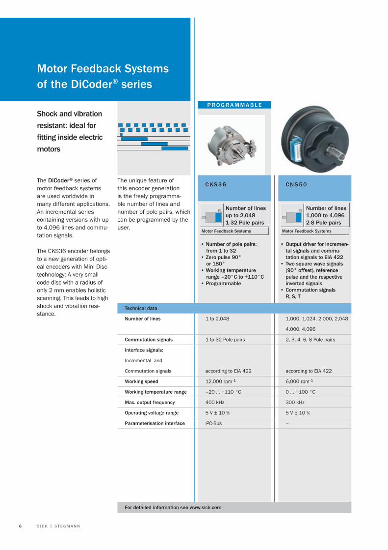
Shock and vibration resistant: ideal for fitting inside electric motors
c k S 3 6 c n S 5 0The Dicoder® series of motor feedback systems are used worldwide in many different applications. An incremental series containing versions with up to 4,096 lines and commu-tation signals.
The CKS36 encoder belongs to a new generation of opti-cal encoders with Mini Disc technology: A very small code disc with a radius of only 2 mm enables holistic scanning. This leads to high shock and vibration resi-stance.
• Number of pole pairs: from 1 to 32• Zero pulse 90° or 180°• Working temperature range –20°c to +110°c• Programmable
technical data
number of lines 1 to 2,048 1,000, 1,024, 2,000, 2,048
4,000, 4,096
commutation signals 1 to 32 Pole pairs 2, 3, 4, 6, 8 Pole pairs
Interface signals:
Incremental- and
Commutation signals according to EIA 422 according to EIA 422
Working speed 12,000 rpm-1 6,000 rpm-1
Working temperature range –20 … +110 °C 0 … +100 °C
Max. output frequency 400 kHz 300 kHz
Operating voltage range 5 V ± 10 % 5 V ± 10 %
Parameterisation interface I2C-Bus –
• Output driver for incremen- tal signals and commu- tation signals to EIa 422• Two square wave signals (90° offset), reference pulse and the respective inverted signals• Commutation signals r, S, t
number of linesup to 2,0481-32 Pole pairs
Motor Feedback Systems
number of lines1,000 to 4,0962-8 Pole pairs
Motor Feedback Systems
The unique feature of this encoder generation is the freely programma-ble number of lines and number of pole pairs, which can be programmed by the user.
P r O G r a M M a b L E
Motor Feedback Systemsof the Dicoder® series
For detailed information see www.sick.com

6 S I c k | S t E G M a n n
Speed control and precise positioning in production robots with Dicoder® motor feedback systems from SIck-StEGMann
M O t O r F E E D b a c k S y S t E M S 7

8 S I c k | S t E G M a n n
For detailed information see www.sick.com
HIPErFacE® – the universal interface
Precision is key! Motor feedback systems ensure precise positioning in packaging robots.
HIPErFacE® motor feedback systems are a mix of incre-mental encoders and absolute encoders and combine the benefits of both encoder types.
Initially, the absolute value is only formed when the device is powered up and is communicated to the exter-nal counter in the controller via the bus-enabled RS 485 parameter interface. From this absolute value, the con-troller continues to count incrementally using the ana-logue sine/cosine signals.
The use of highly-linear sine and cosine signals achieves the high resolution required for speed control (arctan formation within the con-troller).
However, the signal frequen-cies to be transmitted remain relatively low. For instance a unit with 512 periods per revolution, operating at a very high speed of 12,000 RPM, only generates an output frequency of 102.4 kHz which can be easily transmitted over a long distance.
HIPErFacE® retains only one interface with 8 lines, for reduced cabling work.
HIPErFacE® transmits the following data: · commutation · absolute position · Speed · Data from the electronic type label

8 S I c k | S t E G M a n n
these re nowned manu facturers offer you HIPErFacE®
M O t O r F E E D b a c k S y S t E M S 9
1 0 S I c k | S t E G M a n n
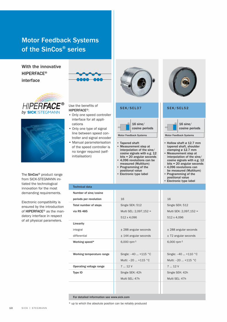
S E k / S E L 3 7 S E k / S E L 5 2
The Sincos® product range from SICK-STEGMANN ini-tiated the technological innovation for the most demanding requirements.
Electronic compatibility is ensured by the introduction of HIPErFacE® as the man-datory interface in respect of all physical parameters.
• Tapered shaft • Measurement step at interpolation of the sine/ cosine signals with e.g. 12 bits = 20 angular seconds• 4,096 revolutions can be measured (Multiturn) • Programming of the positional value• Electronic type label
• Hollow shaft ø 12.7 mm tapered shaft, shoulder clamping ø 12.7 mm• Measurement step at interpolation of the sine/ cosine signals with e.g. 12 bits = 20 angular seconds • 4,096 revolutions can be measured (Multiturn)• Programming of the positional value• Electronic type label
technical data
number of sine/cosine
periods per revolution 16 16
total number of steps Single SEK: 512 Single SEK: 512
via rS 485 Multi SEL: 2,097,152 = Multi SEK: 2,097,152 =
512 x 4,096 512 x 4,096
Linearity
integral ± 288 angular seconds ± 288 angular seconds
differential ± 144 angular seconds ± 72 angular seconds
Working speed* 6,000 rpm-1 6,000 rpm-1
Working temperature range Single: –40 … +115 °C Single: –40 … +110 °C
Multi: –20 ... +115 °C Multi: –20 ... +115 °C
Operating voltage range 7 … 12 V 7 … 12 V
type ID Single SEK: 42h Single SEK: 42h
Multi SEL: 47h Multi SEL: 47h
16 sine/cosine periods
Motor Feedback Systems
16 sine/cosine periods
Motor Feedback Systems
Use the benefits of HIPErFacE®: • Only one speed controller interface for all appli- cations• Only one type of signal line between speed con- troller and signal encoder• Manual parameterisation of the speed controller is no longer required (self- initialisation)
With the innovative HIPErFacE®
interface
For detailed information see www.sick.com
Motor Feedback Systems of the Sincos® series
* up to which the absolute position can be reliably produced

1 0 S I c k | S t E G M a n n
S r S / S r M 5 0
1,024 sine/cosine periods
Motor Feedback Systems
• Plug-in shaft or tapered shaft• Measurement step at interpolation of the sine/ cosine signals with e.g. 12 bits = 0.3 angular seconds • 4,096 revolutions can be measured (Multiturn)• Programming of the positional value • Electronic type label
128 1,024
Single SKS: 4,096 Single SRS: 32,768
Multi SKM: 16,777,216 = Multi SRM: 134,217,728 =
4,096 x 4,096 32,768 x 4,096
± 80 angular seconds ± 45 angular seconds
± 40 angular seconds ± 7 angular seconds
SKS: 12,000 rpm-1 6,000 rpm-1
SKM: 9,000 rpm-1
–20 °C … +110 °C –20°C … +115 °C
7 … 12 V 7 … 12 V
Single SKS: 32h Single SRS: 22h
Multi SKM: 37h Multi SRM: 27h
S k S / S k M 3 6
• Tapered shaft• Measurement step at interpolation of the sine/ cosine signals with e.g. 12 bits = 2.5 angular seconds • 4,096 revolutions can be measured (Multiturn)• Programming of the positional value• Electronic type label
128 sine/cosine periods
Motor Feedback Systems
Sincos® for speed control and synchronisation of the drive motors on printing rollers guarantees excellent printing results.
M O t O r F E E D b a c k S y S t E M S 1 1

1 2 S I c k | S t E G M a n n
S r S / S r M 6 4
• Hollow shafts up to 14 mm in diameter• Measurement step at interpolation of the sine/ cosine signals with e.g. 12 bits = 0.3 angular seconds• 4,096 revolutions can be measured (Multiturn)• Programming of the positional value• Electronic type label
1,024 sine/cosine periods
Motor Feedback Systems
S c k / S c L 2 5 - 5 3
• Hollow shaft diameters ø 25 to 53 mm• Measurement step at interpolation of the sine/ cosine signals with e.g. 12 bits = 0.3 angular seconds• 4,096 revolutions can be measured (Multiturn)• Programming of the positional value• Electronic type label
1,024 sine/cosine periods
Motor Feedback Systems
With the innovative HIPErFacE®
interface
Depending upon the applica-tion, electric drives require the following data from the signal encoders, in the control loop:• Commutation data• Speed data• Position data (absolute)• Position data over several revolutions (absolute)• Data from the electronic type label
All this data can be trans-mitted via HIPErFacE®. technical data
number of sine/cosine
periods per revolution 1,024 1,024
total number of steps Single SCK: 32,768 Single SRS: 32,768
via rS 485 Multi SCL: 134,217,728 = Multi SRM: 134,217,728 =
32,768 x 4,096 32,768 x 4,096
Linearity
integral ± 180 angular seconds ± 45 angular seconds
differential ± 12 angular seconds ± 7 angular seconds
Working speed* 6,000 rpm-1 6,000 rpm-1
Working temperature range –10 … +100 °C –20 … +110 °C
Operating voltage range 7 … 12 V 7 … 12 V
type ID Single SCK: 22h Single SRS: 22h
Multi SCL: 27h Multi SRM: 27h
For detailed information see www.sick.com
Motor Feedback Systems of the Sincos® series
* up to which the absolute position can be reliably produced
1 2 S I c k | S t E G M a n n
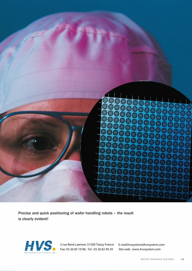
Precise and quick positioning of wafer handling robots – the result is clearly evident!
M O t O r F E E D b a c k S y S t E M S 1 3
2 rue René Laennec 51500 Taissy France Fax: 03 26 85 19 08, Tel : 03 26 82 49 29
E-mail:[email protected] web : www.hvssystem.com

1 4 S I c k | S t E G M a n n
S r S / S r M 5 0 S ta n D a L O n E
• Solid shaft 6 or 10 mm• Measurement step at interpolation of the sine/ cosine signals with e.g. 12 bits = 0.3 angular seconds• 4,096 revolutions can be measured (Multiturn)• Programming of the positional value • Electronic type label
1,024 sine/cosine periods
Motor Feedback Systems
With the innovativeHIPErFacE®-interface
Single- and Multiturn versions in the compact and robust metal housing are mainly used as master encoders. Stand alone devices and a 6 or 10 mm shaft which is connected to the application using a shaft coupling.
The master encoder is used e.g. as a master for the syn-chronisation of several axes. STAND-ALONE motor feed-back systems are increa-singly used in conventional encoder applications as these variants are compatible with commercial encoder mechanisms.
technical data
number of sine/ cosine
periods per revolution 128 1,024
total number of steps Single SKS: 4,096 Single SRS: 32,768
via rS 485 Multi SKM: 16,777,216 = Multi SRM: 134,217,728 =
4,096 x 4,096 32,768 x 4,096
non linearity ± 120 angular seconds ± 52 angular seconds
Working speed* 6,000 min-1 6,000 min-1
Working temperature rage –20 … +100 °C –20 … +85 °C
Operating voltage range 7 … 12 V 7 … 12 V
type ID Single SKS: 32h Single SRS: 22h
Multi SKM: 37h Multi SRM: 27h
S k S / S k M 3 6 S ta n D a L O n E
For detailed information see www.sick.com
Motor Feedback Systems of the Sincos® seriesStanD aLOnE
• Solid shaft 6 mm• Measurement step at interpolation of the sine/ cosine signals with e.g. 12 bits = 2.5 angular seconds• 4,096 revolutions can be measured (Multiturn)• Programming of the positional value • Electronic type label
128 sine/cosine periods
Motor Feedback Systems
* up to which the absolute position can be reliably produced
1 4 S I c k | S t E G M a n n
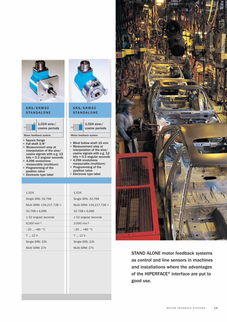
S r S / S r M 5 0 S ta n Da L O n E
1,024 sine-/cosine periods
Motor feedback system
• Blind hollow shaft 15 mm• Measurement step at interpolation of the sine/ cosine signals with e.g. 12 bits = 0.3 angular seconds• 4,096 revolutions measurable (multiturn)• Programming of the position value• Electronic type label
1,024 1,024
Single SRS: 32,768 Single SRS: 32,768
Multi SRM: 134,217,728 = Multi SRM: 134,217,728 =
32,768 x 4,096 32,768 x 4,096
± 52 angular seconds ± 52 angular seconds
6,000 min-1 3,000 min-1
–20 … +85 °C –20 … +85 °C
7 … 12 V 7 ... 12 V
Single SRS: 22h Single SRS: 22h
Multi SRM: 27h Multi SRM: 27h
S r S / S r M 5 0 S ta n D a L O n E
• Square flange• Full shaft 3/8“ • Measurement step at interpolation of the sine/ cosine signals with e.g. 12 bits = 0.3 angular seconds• 4,096 revolutions measurable (multiturn)• Programming of the position value• Electronic type label
1,024 sine-/cosine periods
Motor feedback system
StanD aLOnE motor feedback systems as control and line sensors in machines and installations where the advantages of the HIPErFacE® interface are put to good use.
M O t O r F E E D b a c k S y S t E M S 1 5

1 6 S I c k | S t E G M a n n
With the inovativeHIPErFacE®-interface
The non-contact measuring system consists of a magne-tic tape and a reading head. The magnetic reading head with its integrated evaluation electronics is moved over the magnetic tape and produces a positional output for a linear travel of up to 40 m.This system is used wherever high travelling speed and easy assembly determine the requirements for a reliable measuring system, e.g. in wood and glass processing, on palletisers, paper machinery and robots.
technical date
Measurement length Up to 4 m 0.5 to 40 m
Period length of the sine/ 1 mm 5 mm
cosine periods
resolution 0.24 μm 1.22 μm
System accuracy ± 10 μm typ. ± 0.3 mm/m at 20 °C
Speed of travel max. 10 m/s max. 6 m/s
Working temperature range –30 … +85 °C 0 … +70 °C
Operating voltage range 7 … 12 V 7 … 12 V
type ID FFh 82h
For detailed information see www.sick.com
absolute, non contactlength measuring systemLincoder®
t t k 7 0
• Measurement lengths up to 4 m• Non-contact length measuring system wear free• Absolute position determination, no reference run• IP65
Measurement lengths up to 4 m
Linear encoder
Measurement range 0.5 to 40 m
Linear encoder
• Measurement lengths up to 40 m• Non-contact length measuring system wear free• Absolute position determination, no reference run• IP65
L 2 3 0

1 6 S I c k | S t E G M a n n
Palletiser with an integrated Lincoder® L230 for reliable positioning in a harsh working environment.
M O t O r F E E D b a c k S y S t E M S 1 7
1 8 S I c k | S t E G M a n n
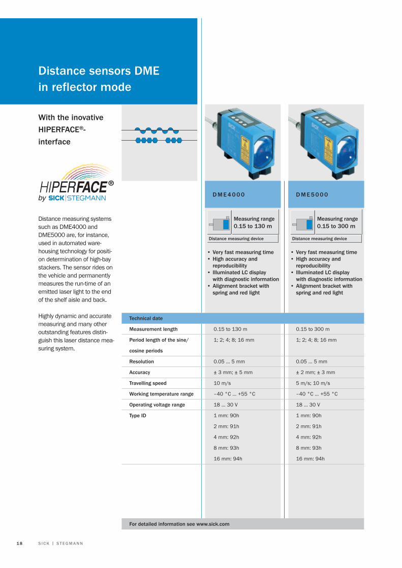
D M E 5 0 0 0
Measuring range0.15 to 300 m
Distance measuring device
D M E 4 0 0 0
Measuring range0.15 to 130 m
Distance measuring device
• Very fast measuring time• High accuracy and reproducibility• Illuminated LC display with diagnostic information• Alignment bracket with spring and red light
With the inovativeHIPErFacE®-interface
Distance measuring systems such as DME4000 and DME5000 are, for instance, used in automated ware-housing technology for positi-on determination of high-bay stackers. The sensor rides on the vehicle and permanently measures the run-time of an emitted laser light to the end of the shelf aisle and back.
Highly dynamic and accurate measuring and many other outstanding features distin-guish this laser distance mea-suring system.
technical date
Measurement length 0.15 to 130 m 0.15 to 300 m
Period length of the sine/ 1; 2; 4; 8; 16 mm 1; 2; 4; 8; 16 mm
cosine periods
resolution 0.05 … 5 mm 0.05 … 5 mm
accuracy ± 3 mm; ± 5 mm ± 2 mm; ± 3 mm
travelling speed 10 m/s 5 m/s; 10 m/s
Working temperature range –40 °C … +55 °C –40 °C … +55 °C
Operating voltage range 18 … 30 V 18 … 30 V
type ID 1 mm: 90h 1 mm: 90h
2 mm: 91h 2 mm: 91h
4 mm: 92h 4 mm: 92h
8 mm: 93h 8 mm: 93h
16 mm: 94h 16 mm: 94h
For detailed information see www.sick.com
Distance sensors DMEin reflector mode
• Very fast measuring time• High accuracy and reproducibility• Illuminated LC display with diagnostic information• Alignment bracket with spring and red light

1 8 S I c k | S t E G M a n n
Precise distance measuring with DME devices forms the basis for position recording on rack operating devices. this means that even in an automated warehouse, every part is in the right place.
M O t O r F E E D b a c k S y S t E M S 1 9

SICK AG | Waldkirch | Germany | www.sick.comSICK STEGMANN GmbH | DonaueschingenGermany | www.sick-stegmann.de
8011
697/
2009
-02
∙ WAS
/SZ
∙ Prin
ted
in G
erm
any
(200
8-04
)Su
bjec
t to
chan
ge w
ithou
t not
ice
∙ STE
G W
B in
t31
Fa c t O r y a u t O M at I O n
With its intelligent sensors, safety sy-stems, and auto ident applications, SICK realises comprehensive solutions for factory automation.
Non-contact detecting, counting, • classifying, and positioning of any types of objectAccident protection and personal sa-• fety using sensors, as well as safety software and services
L O G I S t I c S a u t O M at I O n
Sensors made by SICK form the basis for automating material flows and the optimisation of sorting and warehousing processes.
Automated identification with bar • code and RFID reading devices for the purpose of sorting and target control in industrial material flowDetecting volume, position, and con-• tours of objects and surroundings with laser measurement systems
P r O c E S S a u t O M at I O n
Analyzers and Process Instrumentation by SICK MAIHAK provides for the best possible acquisition of environmental and process data.
Complete systems solutions for gas • analysis, dust measurement, flow rate measurement, water analysis or, respectively, liquid analysis, and level measurement as well as other tasks
O u r c O M P E t E n c E I n t H E b u S I n E S S S E G M E n t S
Worldwide presence with subsidiaries in the following countries:
australia
belgium/Luxembourg
brasil
ceská republika
china
Danmark
Deutschland
España
France
Great britain
India
Israel
Italia
Japan
nederlands
norge
Österreich
Polska
republic of korea
republika Slovenija
românia
russia
Schweiz
Singapore
Suomi
Sverige
taiwan
türkiye
uSa/canada/México
Please find detailed addresses and additional representatives and agencies in all major industrial nations at www.sick.com
www.hvssystem.com
Siège social :2 rue René Laennec51500 TaissyFrance
Contact : [email protected]
Tél : 0326824929Fax : 0326851908
Distribué par :