motor descriptions
DESCRIPTION
yamaha motor companyTRANSCRIPT

Series CJ2Air Cylinder
ø6, ø10, ø16
Series Variations
StandardSeries CJ2
Non-rotating RodSeries CJ2K
Built-in Speed ControllerSeries CJ2Z
Low FrictionSeries CJ2Q
Direct MountSeries CJ2R
Direct Mount, Non-Rotating RodSeries CJ2RK
End lock cylinderSeries CBJ2
Low-speed cylinderSeries CJ2X
6
10
16
10
16
16
42
52
60
68
73
80
85
90
110
94
98
102
106
Refer to Best Pneumatics No. 3.
39
Improved wear resistance
The bearing portions of the rod cover and the clevis have been improved in wear resistance to ensure the longevity of the cylinder.
Reduced piston rod deflectionThe clearance between the bushing and the piston rod has been decreased to achieve higher accuracy, thus decreasing the deflection of the piston rod.
Easy installationThe installation is simple because a tool can be placed directly over the cover for installation.
High speed actuation possibleEither the rubber bumper or the air cushion can be selected according to the drive speed conditions. Therefore, it can support high speed drives.� Rubber bumper······50 to 750 mm/s
(Standard equipment)� Air cushion······50 to 1000 mm/s
Series Action BasicStandard variations Bore size
(mm) PageBuilt-in magnet
With air cushion
Clean series
Copper and fluorine-free
Rod
Singleacting
Doubleacting
Doubleacting
Doubleacting
Singleacting
Singleacting
Singleacting
Doubleacting
Doubleacting
Doubleacting
Single rod
Double rod
Single rod
Single rod
Double rod
Single rod
Doubleacting Single rod
Single rod
Single rod
Single rod,Spring return/Spring extend
Single rod, (Spring return/ Spring extend)
Single rod, (Spring return/ Spring extend)
Single rod, (Spring return/ Spring extend)
CJ1
CJP
CJ2
CM2
CG1
MB
MB1
CA2
CS1
CS2
Individual-X�
D-�
-X�
Technicaldata
P0015-P0124-E.qxd 08.10.2 3:59 PM Page 39

Series CJ2(Standard)
Action/TypeDouble acting
Single rod Double rod
CJ2K(Non-rotating)
Double acting
Single rodSingle rod(spring return)
Single rod(spring extend)
Single rod(spring return)
Single rod(spring extend)
Single acting Single acting
Applicablebore size
Standard
D
CJ2�-�A
10-, 11-
20-
XB6
XB7
XB9
XB13
XC3
XC8
XC9
XC10
XC11
XC22
XC51
X339
X773
Standard
Built-in magnet
Air cushion
Clean series (4)
Copper and Fluorine-free (5)
Heat-resistant cylinder (–10 to 150 °C) (6)(7)
Cold-resistant cylinder (6)(7)
Low-speed cylinder (10 to 50 mm/s) (7)
Low-speed cylinder (5 to 50 mm/s) (7)
Special port position (5)(7)
Adjustable stroke cylinder/Adjustable retraction type (5)(7)
Adjustable stroke cylinder/Adjustable extension type (5)(7)
Dual stroke cylinder/Double rod type (7)
Dual stroke cylinder/Single rod type (7)
Fluororubber seal (7)
With hose nipple
Same as CJ1 mounting dimensions
Short mounting pitch
ø6 to ø16
ø10, ø16
ø6 to ø16
ø6 to ø16
ø10, ø16
ø6 to ø16
ø10, ø16
ø6
ø6 to 16 ø10, ø16
Series CJ2
Symbol Specification
: Standard: Made to Order specifications: Special product (Contact SMC for details.): Not available
Combinations of Standard Products and Made
40
Note 1) ø10 foot style only.Note 2) ø 10 and ø16 double clevis style.Note 3) ø 10 and ø16 only.Note 4) Mounting style: Not compatible with the clevis style. A switch is available in the band mounting style only. Note 5) A switch is available in the band mounting style only.Note 6) Not compatible with cylinders with a switch.Note 7) Not compatible with cylinders with a air cushion.Note 8) Available only for locking at head end.Note 9) Refer to Best Pneumatics No. 3 for low-speed cylinders.Note 10) Available only for locking on rod side.
(1) (2) (2)
(3)
P0015-P0124-E.qxd 08.10.2 3:59 PM Page 40

Series CJ2
Single rod Single rodSingle rod Double rod
Double acting Double acting Double acting Double actingDouble acting
Single rod(spring return)
Single rod(spring extend)
Single rod Single rodSingle rod(spring return)
Single rod(spring extend)
Single acting Single acting
ø10, ø16 ø16
CJ2Z (Built-in speed controller)
CJ2Q (Low friction)
CJ2R(Direct mount)
CJ2RK(Direct mount, Non-rotating)
CBJ2(With end lock)
Double acting
Single rod
ø10, ø16
CJ2XLow-speed cylinder (9)
to Order Specifications
41
(8)
(10)
(10)
CJ1
CJP
CJ2
CM2
CG1
MB
MB1
CA2
CS1
CS2
Individual-X�
D-�
-X�
Technicaldata
P0015-P0124-E.qxd 08.10.2 3:59 PM Page 41

CJ2
With auto switch M9BWCDJ2 L 16 60 A
16 60 A
Band mounting style
CDJ2B10-45-A
CDJ2B16-60-BExample
Rail mounting style
Band mounting style
Bore size6
1016
6 mm
10 mm
16 mmMounting style
BLFD
Basic style
Axial foot style
Rod side flange style
Double clevis style (Except ø6)
Cylinder standard stroke (mm)Refer to the standard stroke table on page 43.
CushionNilA
Rubber bumper
Air cushion (Except ø6)
With auto switch(Built-in magnet)
Auto switch∗ For the applicable auto switch
model, refer to the table below.∗ If a built-in magnet cylinder without
an auto switch is required, refer to the model of built-in magnet cylinder.
Nil
Sn
2 pcs.
1 pc.
“n” pcs.
Number of auto switches
Nil
R—
Axial
ø6
Perpendicular to axis
Axial
ø10, ø16
Head cover port location
Applicable Auto Switch/Refer to pages 1263 to 1371 for further information on auto switches.
(Example) M9NW(Example) M9NWM(Example) M9NWL(Example) M9NWZ(Example) H7CN
∗ Since there are other applicable auto switches than listed, refer to page 123 for details. ∗ For details about auto switches with pre-wired connector, refer to pages 1328 and 1329. ∗ Band mounting style is not available for D-A9�V/M9�V/M9�WV and D-M9�A(V)L types. ∗∗ “D-A79W” cannot be mounted on bore size ø10 cylinder with air cushion.
∗ For rail mounting style, screws and nuts for 2 pcs switches come with the rail.
∗ Refer to page 123 for switch mounting brackets.
L
Made to OrderRefer to page 43 for details.
—
—
Yes
Yes
YesNo
NoYes
Grommet
Grommet
Grommet
Connector
Connector
Grommet
—
200 V
100 V
100 V or less—
24 V or less—
3-wire(NPN equivalent)
2-wire
DC
24V
24V
5 V
—
12 V
—
5 V, 12 V
12 V
5 V, 12 V
12 V
5 V, 12 V
AC
Relay,PLC
Relay,PLC
A96
——
A93A90
C73CC80C
—
M9N—
M9P—
M9B—
H7CM9NW
—M9PW
—M9BW
—H7BAH7NF
—
A72A73—
A80A73CA80C
A79W ∗∗
—F7NV
—F7PV
—F7BVJ79C
—F7NWV
———
F7BWVF7BAV
—
A76H
A72HA73H
—A80H
———
—F79—
F7P—
J79——
F79W—
F7PW—
J79WF7BAF79F
∗ Solid state auto switches marked with “�” are produced upon receipt of order.∗ D-A9�/M9�/M9�W/A7��/A80�/F7��/J7�� auto switches are shipped together (not assembled). (However, when D-A9�/M9�/M9�W types are selected,
only auto switch mounting brackets are assembled before being shipped.)∗ When D-A9�(V)/M9�(V)/M9�W(V) types are mounted on a ø10 or ø16 rail, order auto switch mounting brackets separately. Refer to page 123 for details.
IC circuit
IC circuit
IC circuit
IC circuit
IC circuit
IC circuit
3-wire (NPN)
4-wire (NPN)
3-wire (NPN)
3-wire (PNP)
3-wire (PNP)
2-wire
2-wire
42
Air Cylinder: Standard TypeDouble Acting, Single Rod
Series CJ2ø6, ø10, ø16
How to Order
Built-in Magnet Cylinder ModelSuffix the symbol “-A” (Rail mounting style) or “-B” (Band mounting style) to the end of part number for cylinder with auto switch.
Symbol
Bore size(mm)
∗ For configuration, refer to page 43.∗ Double clevis is only available for being
perpendicular to axis.
Type Special function Electricalentry
Load voltage Lead wire length (m)0.5(Nil)
3(L)
1(M)
5(Z)
None(N)
Applicable loadAuto switch model
Band mounting(ø6, ø10, ø16)
Rail mounting (ø10, ø16)
Perpendicular In-lineIndica
tor lig
ht
Wiring(Output)
Pre-wired connector
Ree
d s
wit
chS
olid
sta
te s
wit
ch
Diagnostic indication(2-color indication)
Water resistant (2-color indication)With diagnostic output (2-color indication)
Diagnostic indication (2-color indication)
∗ Lead wire length symbols: 0.5 m········· 1 m········· 3 m········· 5 m········· None·········
NilMLZN
P0015-P0124-E.qxd 08.10.2 3:59 PM Page 42

106 16Bore size (mm)
Action
Fluid
Proof pressure
Maximum operating pressure
Minimum operating pressure
Ambient and fluid temperature
Cushion
Lubrication
Stroke length tolerance
50 to 750 mm/s
50 to 1000 mm/s
0.012J
—
0.035J 0.090J
0.07J(9.4 mm)
0.18J(9.4 mm)
Specifications
Double acting, Single rod
Air
1 MPa
10.7 MPa
Without auto switch: –10°C to 70°C, With auto switch: –10°C to 60°C ∗
Rubber bumper/Air cushion
Not required (Non-lube)+1.0
0
∗ No freezing
∗ Manufacture of intermediate strokes at 1 mm intervals is possible. (Spacers are not used.)
Bore size
6
10
16
Standard stroke
Standard Stroke (mm)
15, 30, 45, 60
15, 30, 45, 60, 75, 100, 125, 150
15, 30, 45, 60, 75, 100, 125, 150, 175, 200
—XA�—XB6
—XB7
—XB9
—XB13
—XC3
—XC8
—XC9
—XC10
—XC11
—XC22
—XC51
Symbol Specifications
Axial Perpendicular
JIS SymbolDouble acting, Single rod
• Minimum stroke for auto switch mounting• Proper auto switch mounting position (detection at stroke end) and mounting height• Operating range• Switch mounting bracket part no.
Refer to pages 117 to 123 for cylinders with auto switches.
Rubber bumper
Air cushion
Rubber bumper
Air cushion
Rubber bumper
0.12 MPa
—
0.06 MPa
0.1 MPa
Air cushion(Effective cushion length)
43
Made to Order Specifications(For details, refer to pages 1373 to 1498.)
Series CJ2Air Cylinder: Standard TypeDouble Acting, Single Rod
Piston speed
Allowable kinetic energy
Head Cover Port LocationEither perpendicular to the cylinder axis or in-line with the cylinder axis is available for basic style. (ø6 is available only as in-line style.)
Change of rod end shape
Heat resistant cylinder (150°C)
Cold resistant cylinder
Low speed cylinder (10 to 50 mm/s)
Low speed cylinder (5 to 50 mm/s)
Special port location
Adjustable stroke cylinder/Adjustable extension type
Adjustable stroke cylinder/Adjustable retraction type
Dual stroke cylinder/Double rod type
Dual stroke cylinder/Single rod type
Fluororubber seals
With hose nipple
∗ Not available with switch & with air cushion
∗ Not available with switch & with air cushion
∗ Not available with air cushion
∗ Not available with air cushion
∗ Not available with air cushion
∗ Not available with air cushion
CJ1
CJP
CJ2
CM2
CG1
MB
MB1
CA2
CS1
CS2
Individual-X�
D-�
-X�
Technicaldata
P0015-P0124-E.qxd 08.10.2 4:00 PM Page 43

∗ Pin and snap ring are shipped together with double clevis and double knuckle joint.
∗ T-bracket is used with double clevis (D).
Mounting Style and Accessory/For details, refer to page 51.
Mounting Bracket Part No.
6CJ-L006BCJ-F006B
10CJ-L010BCJ-F010BCJ-T010B
16CJ-L016BCJ-F016BCJ-T016B
(g)
6
15
2
8
5
–
–
–
–
10
24
4
8
5
4
16
24
32
16
55
6.5
20
15
10
22
19.5
50
Mass
Be sure to read before handling.Refer to front matters 54 and 55 for Safety Instructions and pages 3 to 11 for Actuator and Auto Switch Precautions.
Precautions
44
Series CJ2
Mounting
Sta
ndar
deq
uipm
ent
Opt
ion
Mounting nut
Rod end nut
Clevis pin
Single knuckle joint
Double knuckle joint ∗
T-bracket
Basicstyle
Axialfoot style
Rod sideflange style
Double ∗clevis style
Mounting bracket
Foot bracketFlange bracketT-bracket ∗
Bore size (mm)
Acc
esso
rybr
acke
t
Mounting
bra
cket
mass
Axial foot style
Rod side flange style
Double clevis style (With pin) ∗
Bore size (mm)
Basic mass ∗
Additional mass per each 15 mm of stroke
Single knuckle joint
Double knuckle joint (With pin)
T-bracket
∗ Mounting nut and rod end nut are included in the basic mass.
∗∗ Mounting nut is not attached to the double clevis style, so the mounting nut mass is already subtracted.
Calculation: (Example) CJ2L10-45 • Basic mass ················ 24 (ø10)• Additional mass ········· 4/15 stroke• Cylinder stroke ·········· 45 stroke• Mounting bracket mass ·· 8 (Axial foot style)
24 + 4/15 x 45 + 8 = 44 g
Mounting
Caution1. During installation, secure the rod cover and
tighten by applying an appropriate tightening force to the retaining but or to the rod cover body. If the head cover is secured or the head cover is tightened, the cover could rotate, leading to the deviation.
2. Tighten the retaining screws to an appropriate tightening torque within the range given below.ø6: 2.1 to 2.5 N·m, ø10: 5.9 to 6.4 N·m, ø16: 10.8 to 11.8 N·m
3. To remove and install the retaining ring for the knuckle pin or the clevis pin, use an appropriate pair of pliers (tool for installing a type C retaining ring). In particular, use a pair of ultra-mini pliers for removing and installing the retaining ring on the ø10 cylinder.
4. In the case of auto switch rail mounting style, do not remove the rail that is mounted. Because retaining screws extend into the cylinder, this could lead to an air leak.
5. Please contact SMC when the stroke exceeds 100 mm for the axial foot mounting style.
P0015-P0124-E.qxd 08.10.2 4:00 PM Page 44

Low-speed Cylinder
Smooth operation with a little sticking and slipping at low speed.Can start smoothly with a little ejection even after being rendered for hours.
CJ2 X
Low-speed Cylinder
Copper and Fluorine-free Cylinder (For CRT manufacturing process)
Double acting, Single rod
6, 10, 16
0.7 MPa
0.14 MPa
0.08 MPa
Rubber bumper/Air cusion
Same as standard type. (Refer to page 43.)
Mountable (Band mounting style)
Specifications
ø6
ø10, ø16
ø6
ø10, ø16
Basic style, Axial foot style,Rod side flange style
Double acting, Single rod
6, 10, 16
0.7 MPa
0.12 MPa
0.06 MPa
Rubber bumper (Standard equipment)
Same as standard type. (Refer to page 43.)
Mountable (Band mounting style)
Specifications
Basic style, Axial foot style, Rod side flange style,Double clevis style (Except ø6)
ø10
ø16
Double acting, Single rod
10, 16
Air
1.05 MPa
0.7 MPa
0.06 MPa
Rubber bumper (Standard equipment)
Not required (Non-lube)
1 to 300 mm/s
0.035 J
0.090 J
Specifications
For details, refer to the separate catalog “Pneumatic Clean Series”.
Refer to Best Pneumatics No. 3.
Construction Construction
+1.0 0
Without auto switch: –10 to 70°CWith auto switch: –10 to 60°C (No freezing)
Action
Bore size (mm)
Fluid
Proof pressure
Maximum operating pressure
Minimum operating pressure
Ambient and fluid temperature
Cushion
Lubrication
Stroke length tolerance
Piston speed
Allowable kinetic energy
45
Series CJ2Air Cylinder: Standard TypeDouble Acting, Single Rod
Clean Series
Mounting style Bore size Stroke Head coverport location10-CJ2
Clean Series
Air cylinder which is applicable for the system which discharges leakage from the rod section directly into the outside of clean room by relief port and making an actuator’s rod section having a double seal construction.
Action
Bore size (mm)
Maximum operating pressure
Cushion
Standard stroke (mm)
Auto switch
Minimum operatingpressure
Mounting
Action
Bore size (mm)
Maximum operating pressure
Cushion
Standard stroke (mm)
Auto switch
Minimum operatingpressure
Mounting
Mounting style Bore size Stroke Head coverport location20-CJ2
Copper and fluorine-free
Eliminates the effects by copper based ions and fluorine based resins, etc. over the color cathode ray tube.Making copper based materials into electroless nickel plated treatment or changing them to the non-copper materials in order to prevent copper ions from generating.
Mounting style Bore size Stroke
CJ1
CJP
CJ2
CM2
CG1
MB
MB1
CA2
CS1
CS2
Individual-X�
D-�
-X�
Technicaldata
P0015-P0124-E.qxd 08.10.2 4:00 PM Page 45

CJ2�6-R
Piston construction whenauto switch is mounted.
Piston construction whenauto switch is mounted.
CJ2�10, CJ2�16
With air cushion
Note
Anodized
Anodized
Nickel plated
Nickel plated
Anodized
No.
1
2
3
4
5
6
7
8
9 ∗
10
11
12
13
Component PartsDescription
Rod cover
Head cover
Cylinder tube
Piston rod
Piston
Mounting nut
Rod end nut
Bumper
Seal retainer
Piston seal
Rod seal
Tube gasket
Piston gasket
Material
Aluminum alloy
Aluminum alloy
Stainless steel
Stainless steel
Brass
Brass
Rolled steel
Urethane
Aluminum alloy
NBR
NBR
NBR
NBR
∗ Only for ø6
NoteNo.
14
15
16
17
18
19
Dedicated for with Air Cushion TypeDescription
Cushion needle
Steel balls
Cushion ring
Check seal
Needle seal
Cushion ring gasket
Material
Stainless steel
Bearing steel
Brass
NBR
NBR
NBR
46
Series CJ2
Construction (Not able to disassemble)
Magnet
Piston
Magnet
Piston
P0015-P0124-E.qxd 08.10.2 4:00 PM Page 46

Head cover port location: Axial location (R)
Head cover port location: Axial location (R)
CJ2B6
CJ2B10, 16
2.43.24
Material: Iron
NTJ-006ANTJ-010ANTJ-015A
Part no.Applicablebore (mm)
61016
B
5.578
C
6.48.19.2
d
M3 x 0.5M4 x 0.7M5 x 0.8
H
Z77
74
75
Bore size (mm)
61016
A15
15
15
B12
12
18.3
C14
14
20
D3
4
5
F8
8
8
GA14.5
8
8
GB–
5
5
H28
28
28
MMM3 x 0.5
M4 x 0.7
M5 x 0.8
NA16
12.5
12.5
NB7
9.5
9.5
NDh8 NNM6 x 1.0
M8 x 1.0
M10 x 1.0
S49
46
47
T3
–
–
0–0.018
0–0.022
0–0.022
6
8
10
(mm)
Bore size (mm)
1016
B15
18.3
C17
20
GA7.5
7.5
GB6.5
6.5
NA21
21
NB20
20
WA14.5
14.5
WB13.5
13.5
WW4.5
5.5
S65
66
Z93
94
(mm)With Air Cushion/Dimensions other than the table below are the same as the table above.
Rod End Nut
B 0 –0
.3
8 0 –0
.3
B 0 –0
.3B
0 –0.3
47
Series CJ2Air Cylinder: Standard TypeDouble Acting, Single Rod
Head cover port location
Basic Style (B)
CJ2B Bore size Stroke
With air cushion: CJ2B Head cover port locationBore size Stroke A
∗ For details of the mounting nut, refer to page 51.
Mounting nut ∗
Rod end nut
Mounting nut ∗
Rod end nut
Piping port M5 x 0.8Piping port M5 x 0.8
Piping port 2 x M5 x 0.8
S + Stroke
Z + Stroke
S + StrokeZ + Stroke
Piping port
M5 x 0.8
Piping port 2 x M5 x 0.8
Mounting nut ∗
Rod end nut
S + StrokeZ + Stroke
Piping port
M5 x 0.8
CJ1
CJP
CJ2
CM2
CG1
MB
MB1
CA2
CS1
CS2
Individual-X�
D-�
-X�
Technicaldata
P0015-P0124-E.qxd 08.10.2 4:00 PM Page 47

CJ2L6
CJ2L10, 16
2.43.24
Material: Iron
NTJ-006ANTJ-010ANTJ-015A
Part no.
61016
B
5.578
C
6.48.19.2
d
M3 x 0.5M4 x 0.7M5 x 0.8
H
With Air Cushion/Dimensions other than the table below are the same as the table above.
Bore size (mm)
6
10
16
A
15
15
15
B
12
12
18.3
C
14
14
20
D
3
4
5
F
8
8
8
GA
14.5
8
8
GB
–
5
5
H
28
28
28
LB
15
15
23
LC
4.5
4.5
5.5
LH
9
9
14
LT
1.6
1.6
2.3
LX
24
24
33
LY
16.5
16.5
25
LZ
32
32
42
MM
M3 x 0.5
M4 x 0.7
M5 x 0.8
NA
16
12.5
12.5
NB
7
9.5
9.5
NN
M6 x 1.0
M8 x 1.0
M10 x 1.0
S
49
46
47
T
3
–
–
X
5
5
6
Y
7
7
9
Z
77
74
75
Bore size (mm)
10
16
Z
93
94
B
15
18.3
C
17
20
GA
7.5
7.5
GB
6.5
6.5
LB
16.5
23
NA
21
21
NB
20
20
WA
14.5
14.5
WB
13.5
13.5
WW
4.5
5.5
S
65
66
(mm)
B 0
–0
.3B
0
–0.3
B 0
–0
.3
8 0
–0
.3
48
Series CJ2
Axial Foot Style (L)
CJ2L Head cover port locationBore size Stroke
With air cushion: CJ2L Head cover port locationBore size Stroke A
Rod End Nut
Applicablebore (mm)
∗ For details of the mounting nut, refer to page 51.
Mounting nut ∗
S + StrokeZ + Stroke
S + StrokeZ + Stroke
Cover surface
Cover surface
Rod end nut
Mounting nut ∗
Rod end nut
2 x øLC
Mounting hole
Piping port M5 x 0.8
Piping port
M5 x 0.8
Piping port
M5 x 0.8
Rod cover side Head cover side
Head cover port location:Axial location (R)
Piping port 2 x M5 x 0.8
S + StrokeZ + Stroke
Mounting nut∗
Cover surface
Rod end nut Piping port
M5 x 0.8
Head cover port location:Axial location (R)
Piping port 2 x M5 x 0.8
P0015-P0124-E.qxd 08.10.2 4:00 PM Page 48

CJ2F6
CJ2F10, 16
NTJ-006ANTJ-010ANTJ-015A
61016
B
5.5
7
8
C
6.4
8.1
9.2
d
M3 x 0.5
M4 x 0.7
M5 x 0.8
H
2.4
3.2
4
(mm)
With Air Cushion/Dimensions other than the table below are the same as the table above. (mm)
Bore size (mm)
61016
A15
15
15
B12
12
18.3
C14
14
20
D3
4
5
F8
8
8
FB13
13
19
FC4.5
4.5
5.5
FT1.6
1.6
2.3
FX24
24
33
FY14
14
20
FZ32
32
42
GA14.5
8
8
Bore size (mm)
1016
B15
18.3
C17
20
FB14.5
19
GA7.5
7.5
GB6.5
6.5
NA21
21
NB20
20
WA14.5
14.5
WB13.5
13.5
WW4.5
5.5
S65
66
Z93
94
GB–
5
5
H28
28
28
MMM3 x 0.5
M4 x 0.7
M5 x 0.8
NNM6 x 1.0
M8 x 1.0
M10 x 1.0
NA16
12.5
12.5
NB7
9.5
9.5
S49
46
47
T3
–
–
Z77
74
75
B 0
–0
.3
B 0
–0
.3B
0
–0.3
8 0
–0
.3
49
Series CJ2Air Cylinder: Standard TypeDouble Acting, Single Rod
Rod Side Flange Style (F)
Head cover port locationCJ2F Bore size Stroke
With air cushion: CJ2F Head cover port locationBore size Stroke A
Material: Iron
Rod End Nut
Part no.Applicablebore (mm)
∗ For details of the mounting nut, refer to page 51.
Cover surface
2 x øFC
Mounting hole
2 x øFC
Mounting hole
Mounting nut ∗
Rod end nut
Mounting nut ∗
Mounting nut ∗
Rod end nut
Piping port M5 x 0.8Piping port
M5 x 0.8
Piping port
M5 x 0.8
Piping port
M5 x 0.8
S + Stroke
Z + Stroke
S + Stroke
Z + Stroke
S + Stroke
Z + Stroke
Rod coverside
Piping port 2 x M5 x 0.8
Piping port 2 x M5 x 0.8
Head cover port location:Axial location (R)
Head cover port location:Axial location (R)
Head coverside
Cover surface
Cover surface Rod end nut
CJ1
CJP
CJ2
CM2
CG1
MB
MB1
CA2
CS1
CS2
Individual-X�
D-�
-X�
Technicaldata
P0015-P0124-E.qxd 08.10.2 4:00 PM Page 49

∗ Clevis pin and retaining ring are shipped together.
∗ Clevis pin and retaining ring are shipped together.NTJ-010ANTJ-015A
1016
B
78
C
8.19.2
d
M4 x 0.7M5 x 0.8
H
3.24
Bore size (mm)
1016
A15
15
Bore size (mm)
1016
TC4.5
5.5
TH29
35
TV40
48
TW22
28
TX32
38
TY12
16
Bore size (mm)
1016
B15
18.3
C17
20
CZ15
18.3
GA7.5
7.5
GB19.5
24.5
NA21
21
NB33
38
S65
66
WA14.5
14.5
WB26.5
31.5
WW4.5
5.5
Z101
104
ZZ112
118
B12
18.3
C14
20
CD(cd)3.3
5
CX3.2
6.5
CZ12
18.3
D4
5
GA8
8
GB18
23
H28
28
MMM4 x 0.7
M5 x 0.8
NA12.5
12.5
NB22.5
27.5
R5
8
S46
47
U8
10
Z82
85
ZZ93
99
(mm)
T-bracket Dimensions
With Air Cushion/Dimensions other than the table below are the same as the table above.
(mm)
(mm)
Rod End Nut
B0
-0
.3B
0
-0.3
CZ
0
-0.3
CZ
0
-0.3
50
Series CJ2
Double Clevis Style (D)
CJ2D Bore size Stroke
With air cushion: CJ2D Bore size Stroke A
Material: Iron
Part no. Applicablebore (mm)
T-bracket
For details, refer to page 51.
T-bracket
For details, refer to page 51.
Rod end nut
Rod end nut
Z + Stroke
S + Stroke
Z + Stroke
S + Stroke
Piping port 2 x M5 x 0.8
Piping port 2 x M5 x 0.8
øCDH9
Clevis pin(øcdd9 )
ZZ + Stroke
ZZ + Stroke
+0.030 0
–0.030 –0.060
øCDH9
Clevis pin(øcdd9 )
+0.030 0
–0.030 –0.060
P0015-P0124-E.qxd 08.10.2 4:00 PM Page 50
4 x øTC
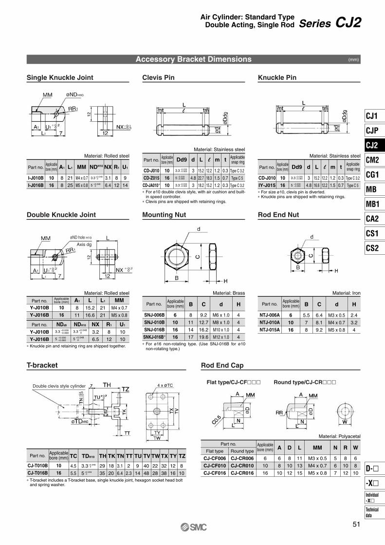
Accessory Bracket Dimensions (mm)
Single Knuckle Joint Clevis Pin Knuckle Pin
Double Knuckle Joint
T-bracket Rod End Cap
Mounting Nut Rod End Nut
Part no. A1 L1 MM NXNDH10
I-J010B
I-J016B
10
16
8
8
21
25
3.1
6.4
R1
8
12
U1
9
14
M4 x 0.7
M5 x 0.8
3.3
5.3
Applicablebore (mm) Part no.
CD-J010
IY-J015
10
16
Applicablebore (mm)
Part no. Dd9
CD-J010
CD-Z015
CD-JA010∗
10
16
10
d
3
4.8
3
L
15.2
22.7
18.2
l
12.2
18.3
15.2
m
1.2
1.5
1.2
t
0.3
0.7
0.3
Type C 3.2
Type C 5
Type C 3.2
Applicablebore (mm)
Applicable snap ring
+0.048 0
+0.048 0
3.3
5.3
3.3
–0.030–0.060
–0.030–0.060
–0.030–0.060
∗ For size ø10, clevis pin is diverted. ∗ Knuckle pins are shipped with retaining rings.
Material: Rolled steelMaterial: Stainless steel
Material: Stainless steel
Dd9 d
3
4.8
L
15.2
16.6
l
12.2
12.2
m
1.2
1.5
t
0.3
0.7
Type C 3.2
Type C 5
Applicable snap ring
3.3
5.3
–0.030–0.060
–0.030–0.060
Part no.
Y-J010B
Y-J016B
10
16
Part no. B
SNJ-006B
SNJ-010B
SNJ-016B
SNKJ-016B∗
6
10
16
16
8
11
14
17
C
9.2
12.7
16.2
19.6
d
M6 x 1.0
M8 x 1.0
M10 x 1.0
M12 x 1.0
H
4
4
4
4
Applicablebore (mm)
Material: Rolled steel Material: BrassApplicablebore (mm) A1
8
11
Part no.
Y-J010B
Y-J016B
NDd9 NDH10
L15.2
16.6
NX3.2
6.5
R1
8
12
U1
10
10
L1
21
21
MMM4 x 0.7
M5 x 0.8
3.3
5.3
–0.030–0.060
–0.030–0.060
3.3
5.3
Part no. B
NTJ-006A
NTJ-010A
NTJ-015A
6
10
16
5.5
7
8
C
6.4
8.1
9.2
d
M3 x 0.5
M4 x 0.7
M5 x 0.8
H
2.4
3.2
4
Applicablebore (mm)
Material: Iron
∗ Knuckle pin and retaining ring are shipped together.
∗ T-bracket includes a T-bracket base, single knuckle joint, hexagon socket head bolt and spring washer.
Part no.
CJ-T010B
CJ-T016B
10
16
TC
4.5
5.5
TH
29
35
TK
18
20
TN
3.1
6.4
TT
2
2.3
TU
9
14
TV
40
48
TW
22
28
TX
32
38
TY
12
16
TZ
8
10
Applicablebore (mm) TDH10
3.3
5.3
+0.048 0
+0.048 0
Part no.
Flat type
CJ-CF006
CJ-CF010
CJ-CF016
Applicablebore (mm)Round type
CJ-CR006
CJ-CR010
CJ-CR016
6
10
16
A
6
8
10
D
8
10
12
L
11
13
15
R
8
10
12
N
5
6
7
W
6
8
10
MM
M3 x 0.5
M4 x 0.7
M5 x 0.8
Material: Polyacetal
Flat type/CJ-CF��� Round type/CJ-CR���
1212
51
Series CJ2Air Cylinder: Standard TypeDouble Acting, Single Rod
∗ For ø10 double clevis style, with air cushion and built-in speed controller.
∗ Clevis pins are shipped with retaining rings.
øND hole H10
Axis dg
+0.048 0
+0.048 0
∗ For ø16 non-rotating type. (Use SNJ-016B for ø10 non-rotating type.)
Double clevis style cylinder
CJ1
CJP
CJ2
CM2
CG1
MB
MB1
CA2
CS1
CS2
Individual-X�
D-�
-X�
Technicaldata
P0015-P0124-E.qxd 08.10.2 4:00 PM Page 51

CDJ2WWith auto switch
CJ2W L
Bore size6
1016
6 mm
10 mm
16 mm
Mounting styleBLF
Basic style
Foot style
Flange style
Cylinder standard stroke (mm)Refer to the standard stroke table on page 53.
With auto switch(Built-in magnet)
Built-in Magnet Cylinder Model
CDJ2WB16-60-A
CDJ2WB10-45-BExample
Rail mounting style
Band mounting style
Suffix the symbol “-A” (Rail mounting style) or “-B” (Band mounting style) to the end of part number for cylinder with auto switch.
∗ For rail mounting style, screws and nuts for 2 pcs switches come with the rail.
∗ Refer to page 123 for switch mounting brackets.
Applicable Auto Switch/Refer to pages 1263 to 1371 for further information on auto switches.
L
—
200 V
100 V
100 V or less—
24 V or less—
DC
24 V
24 V
5 V
—
12 V
—
5 V, 12 V
12 V
5 V, 12 V
12 V
5 V, 12 V
AC
A96
——
A93A90
C73CC80C
—
M9N—
M9P—
M9B—
H7CM9NW
—M9PW
—M9BW
—H7BA
H7NF ∗∗∗
—
A72A73—
A80A73CA80C
A79W ∗∗
—F7NV
—F7PV
—F7BVJ79C
—F7NWV
———
F7BWVF7BAV
—
A76H
A72HA73H
—A80H
———
—F79—
F7P—
J79——
F79W—
F7PW—
J79WF7BAF79F
—
—
16
16 45
45 A M9BW
A
CushionNilA
Rubber bumper
Air cushion
Auto switch
Nil
Sn
2 pcs.
1 pc.
“n” pcs.
Number of auto switches
Made to OrderRefer to page 53 for details.
∗ For the applicable auto switch model, refer to the table below.
∗ If a built-in magnet cylinder without an auto switch is required, refer to the model of built-in magnet cylinder.
Yes
Yes
YesNo
NoYes
Grommet
Grommet
Grommet
Connector
Connector
Grommet
3-wire(NPN equivalent)
2-wire
3-wire (NPN)
4-wire (NPN)
3-wire (NPN)
3-wire (PNP)
3-wire (PNP)
2-wire
2-wire
Relay,PLC
Relay,PLC
IC circuit
IC circuit
IC circuit
IC circuit
IC circuit
IC circuit
(Example) M9NW(Example) M9NWM(Example) M9NWL(Example) M9NWZ(Example) H7CN
∗ Since there are other applicable auto switches than listed, refer to page 123 for details. ∗ For details about auto switches with pre-wired connector, refer to pages 1328 and 1329. ∗ Band mounting style is not available for D-A9�V�/M9�V�/M9�WV� and D-M9�A(V)L types. ∗∗ “D-A79W” cannot be mounted on bore size ø10 cylinder with air cushion.
∗∗∗ “D-H7NF” cannot be mounted on bore size ø6 cylinder.∗ Solid state auto switches marked with “�” are produced upon receipt of order.∗ D-A9�/M9�/M9�W/A7��/A80�/F7��/J7�� auto switches are shipped together (not assembled). (However, when D-A9�/M9�/M9�W types are selected,
only auto switch mounting brackets are assembled before being shipped.)∗ When D-A9�(V)/M9�(V)/M9�W(V) types are mounted on a ø10 or ø16 rail, order auto switch mounting brackets separately. Refer to page 123 for details.
52
Air Cylinder: Standard TypeDouble Acting, Double Rod
Series CJ2Wø6, ø10, ø16
How to Order
Type Special function Electricalentry Ind
icator
light
Ree
d s
wit
chS
olid
sta
te s
wit
ch
Diagnostic indication(2-color indication)
Water resistant (2-color indication)With diagnostic output (2-color indication)
Diagnostic indication (2-color indication)
Wiring(Output)
Load voltage Lead wire length (m)0.5(Nil)
3(L)
1(M)
5(Z)
None(N)
Applicable loadAuto switch model
Band mounting(ø6, ø10, ø16)
Rail mounting (ø10, ø16)
Perpendicular In-line
Pre-wired connector
∗ Lead wire length symbols: 0.5 m········· 1 m········· 3 m········· 5 m········· None·········
NilMLZN
P0015-P0124-E.qxd 08.10.2 4:00 PM Page 52

10 166Bore size (mm)
Action
Fluid
Proof pressure
Maximum operating pressure
Minimum operating pressure
Ambient and fluid temperature
Cushion
Lubrication
Stroke length tolerance
Piston speed
Allowable kinetic energy
50 to 750 mm/s
50 to 1000 mm/s
0.035 J
Specifications
Double acting, Double rod
Air
1 MPa
0.7 MPa
0.1 MPa
Without auto switch: –10°C to 70°C, With auto switch: –10°C to 60°C ∗
Rubber bumper/Air cushion
Not required (Non-lube)+1.0
0
∗ No freezing
Bore size (mm)
6, 10, 16
Standard stroke
15, 30, 45, 60
Standard Stroke (mm)
∗ Manufacture of intermediate strokes at 1 mm intervals is possible. (Spacers are not used.)
JIS SymbolDouble acting, Double rod
• Minimum stroke for auto switch mounting• Proper auto switch mounting position (detection at stroke end) and mounting height• Operating range• Switch mounting bracket part no.
Refer to pages 117 to 123 for cylinders with auto switches.
Rubber bumper
Air cushion
Rubber bumper
Air cushion
Rubber bumper
Air cushion(Effective cushion length)
0.1 MPa—
—
0.012 J 0.090 J
0.18 J(9.4 mm)
0.07 J(9.4 mm)
53
Made to Order Specifications(For details, refer to pages 1373 to 1498.)
Series CJ2WAir Cylinder: Standard TypeDouble Acting, Double Rod
Change of rod end shape
Symbol Specifications
–XA�
–XB6
–XB7
–XC22
–XC51
Heat resistant cylinder (150°C)∗ Not available with switch & with air cushion
Cold resistant cylinder∗ Not available with switch & with air cushion
Fluororubber seals∗ Not available with air cushion
With hose nipple
CJ1
CJP
CJ2
CM2
CG1
MB
MB1
CA2
CS1
CS2
Individual-X�
D-�
-X�
Technicaldata
P0015-P0124-E.qxd 08.10.2 4:00 PM Page 53

Mounting Style and Accessory/For details, refer to page 51.
∗ Knuckle pin and retaining ring are shipped together with double knuckle joint.
Bore size (mm) 627
3
16
5
1035
6
16
5
1670
9
40
15
Mass (g)
Mounting Bracket Part No.Bore size (mm)
10
CJ-L010B
CJ-F010B
16
CJ-L016B
CJ-F016B
6
CJ-L006B
CJ-F006B
Be sure to read before handling.Refer to front matters 54 and 55 for Safety Instructions and pages 3 to 11 for Actuator and Auto Switch Precautions.
Precautions
54
Series CJ2W
Mounting Basic style Foot style Flange style
Standardequipment
Option
Mounting nut
Rod end nut
Single knuckle joint
Double knuckle joint ∗
Mounting bracket
Foot bracket
Flange bracket
Basic mass ∗
Additional mass per each 15 mm of stroke
Mounting bracketmass
Foot style
Flange style
Theoretical Output
∗ Mounting nut and rod end nut are included in the basic mass.
Calculation: (Example)CJ2WL10-45• Basic mass ······························ 35 (ø10)• Additional mass ······················· 6/15 stroke• Cylinder stroke ························· 45 stroke• Mounting bracket mass ············ 16 (Foot style)
35 + 6/15 x 45 + 16 = 69 g• For accessory bracket mass, refer to page 44.
Refer to “Double acting cylinder” in Theoretical Output 1 of Technical data 3 on page 1573.In the case of the double rod style, the force at IN side will be its theoretical output.
Mounting
Caution1. During installation, secure the rod cover and
tighten by applying an appropriate tightening force to the retaining but or to the rod cover body. If the head cover is secured or the head cover is tightened, the cover could rotate, leading to the deviation.
2. Tighten the retaining screws to an appropriate tightening torque within the range given below.ø6: 2.1 to 2.5 N·m, ø10: 5.9 to 6.4 N·m, ø16: 10.8 to 11.8 N·m
3. To remove and install the retaining ring for the knuckle pin, use an appropriate pair of pliers (tool for installing a type C retaining ring for hole). In particular, use a pair of ultra-mini pliers for removing and installing the retaining rings on the ø10 cylinder.
4. In the case of auto switch rail mounting style, do not remove the rail that is mounted. Because retaining screws extend into the cylinder, this could lead to an air leak.
P0015-P0124-E.qxd 08.10.2 4:00 PM Page 54

For details, refer to the separate catalog “Pneumatic Clean Series”.
Action
Bore size (mm)
Maximum operating pressure
Minimum operating pressure
Cushion
Standard stroke (mm)
Auto switch
Mounting
SpecificationsDouble acting, Double rod
10, 16
0.7 MPa
0.1 MPa
Rubber bumper
Same as standard type. (Refer to page 53.)
Mountable (Band mounting style)
Basic style, Foot style, Flange style
Eliminates the effects by copper based ions and fluorine based resins, etc. over the color cathode ray tube.Making copper based materials into electroless nickel plated treatment or changing them to the non-copper materials in order to prevent copper ions from generating.
Action
Bore size (mm)
Maximum operating pressure
Minimumoperating pressure
Cushion
Standard stroke (mm)
Auto switch
Mounting
ø6
ø10, ø16
Double acting, Double rod
6, 10, 16
0.7 MPa
0.15 MPa
0.1 MPa
Rubber bumper
15, 30, 45, 60
Mountable (Band mounting style)
Basic style, Foot style, Flange style
Specifications
Copper and Fluorine-free Air Cylinder (For CRT manufacturing process)
55
Series CJ2WAir Cylinder: Standard TypeDouble Acting, Double Rod
Clean Series
10
Clean Series
-CJ2W
Air cylinder which is applicable for the system which discharges leakage from the rod section directly into the outside of clean room by relief port and making an actuator’s rod section having a double seal construction.
Bore sizeMounting style Stroke
Construction (Not able to disassemble)
Copper and fluorine-free
20-CJ2W Bore sizeMounting style Stroke
CJ1
CJP
CJ2
CM2
CG1
MB
MB1
CA2
CS1
CS2
Individual-X�
D-�
-X�
Technicaldata
P0015-P0124-E.qxd 08.10.2 4:00 PM Page 55

With air cushion
Component Parts Dedicated for with Air Cushion TypeNo.
1
2
3
4
5
6
7
8
9
10
11
Description Material
Aluminum alloy
Stainless steel
Stainless steel
Brass
Brass
Rolled steel
Urethane
NBR
NBR
NBR
NBR
Note
Anodized
Nickel plated
Nickel plated
Rod cover
Cylinder tube
Piston rod
Piston
Mounting nut
Rod end nut
Bumper
Piston seal
Rod seal
Tube gasket
Piston gasket
No.
12
13
14
15
16
17
Description Material
Stainless steel
Bearing steel
Brass
NBR
NBR
NBR
Note
Cushion needle
Steel balls
Cushion ring
Check seal
Cushion ring gasket
Needle seal
56
Series CJ2W
Construction (Not able to disassemble)
P0015-P0124-E.qxd 08.10.2 4:00 PM Page 56

Part no.
NTJ-006ANTJ-010ANTJ-015A
Applicablebore (mm)
61016
B
5.5
7
8
C
6.4
8.1
9.2
d
M3 x 0.5
M4 x 0.7
M5 x 0.8
H
2.4
3.2
4
Material: Iron
∗ For details of the mounting nut, refer to page 51.
Bore size (mm) A B C D F GA H
Bore size (mm)
1016
B15
18.3
C17
20
GA7.5
7.5
NA21
21
WA14.5
14.5
WW4.5
5.5
S66
67
Z122
123
MM NA ND h8 NN S ∗ T Z ∗
6 15 12 14 3 8 14.5 28 M3 x 0.5 16 6 M6 x 1.061
(66)3
117(122)
(mm)
0 –0.018
1016
15
15
12
18.3
14
20
4
5
8
8
8
8
28
28
M4 x 0.7
M5 x 0.8
12.5
12.5
8 M8 x 1.0
M10 x 1.0
49
50
–
–
105
106
0 –0.022
10 0 –0.022
∗ ( ) in S and Z dimensions: With auto switchWith Air Cushion/Dimensions other than the table below are the same as the table above.
B0 -0.3
B0 –0
.3
B0 –0
.3
57
Series CJ2WAir Cylinder: Standard TypeDouble Acting, Double Rod
Basic Style (B)
CJ2WB Bore size Stroke
With air cushion: CJ2WB ABore size Stroke
Rod End Nut
CJ2WB6Rod cover Rod end nut
Mounting nut ∗
Rod end nut
Piping port 2 x M5 x 0.8
Piping port 2 x M5 x 0.8
S + StrokeZ + 2 x Stroke
S + StrokeZ + 2 x Stroke
H + Stroke
Mounting nut ∗
Mounting nut ∗
Rod end nutPiping port 2 x M5 x 0.8
S + Stroke Z + 2 x Stroke
CJ1
CJP
CJ2
CM2
CG1
MB
MB1
CA2
CS1
CS2
Individual-X�
D-�
-X�
Technicaldata
P0015-P0124-E.qxd 08.10.2 4:00 PM Page 57

Part no.
NTJ-006ANTJ-010ANTJ-015A
Applicablebore (mm)
61016
B
5.5
7
8
C
6.4
8.1
9.2
d
M3 x 0.5
M4 x 0.7
M5 x 0.8
H
2.4
3.2
4
Material: Iron
∗ For details of the mounting nut, refer to page 51.
Bore size (mm) A
Bore size (mm)
1016
B15
18.3
GA7.5
7.5
LB16.5
23
NA21
21
WA14.5
14.5
WW4.5
5.5
S66
67
Z122
123
MM NA NN S ∗ T Z ∗
6 15 M3 x 0.5 16 M6 x 1.061
(66)3
117(122)
(mm)
1016
15
15
D
3
4
5
F
8
8
8
GA
14.5
8
8
H
28
28
28
LB
15
15
23
LC
4.5
4.5
5.5
LH
9
9
14
LT
1.6
1.6
2.3
LX
24
24
33
LY
16.5
16.5
25
LZ
32
32
42
M4 x 0.7
M5 x 0.8
12.5
12.5
M8 x 1.0
M10 x 1.0
49
50
–
–
X
5
5
6
Y
7
7
9
105
106
∗ ( ) in S and Z dimensions: With auto switchWith Air Cushion/Dimensions other than the table below are the same as the table above.
58
Series CJ2W
Foot Style (L)
CJ2WL Bore size Stroke
With air cushion: CJ2WL ABore size Stroke
Rod End Nut
Mounting nut ∗
Mounting nut ∗
Rod end nut
Rod end nut
Piping port 2 x M5 x 0.8
Piping port 2 x M5 x 0.8
S + Stroke
Z + 2 x Stroke
S + Stroke
Z + 2 x Stroke
Cover surface
2 x øLCMounting hole
H + Stroke
Mounting nut ∗
Rod end nutPiping port 2 x M5 x 0.8
S + StrokeZ + 2 x Stroke
Cover surface
P0015-P0124-E.qxd 08.10.2 4:00 PM Page 58
Part no.
NTJ-006ANTJ-010ANTJ-015A
Applicablebore (mm)
61016
B
5.5
7
8
C
6.4
8.1
9.2
d
M3 x 0.5
M4 x 0.7
M5 x 0.8
H
2.4
3.2
4
Material: Iron
∗ For details of the mounting nut, refer to page 51.
Bore size (mm) A
Bore size (mm)
1016
B15
18.3
FB14.5
19
GA7.5
7.5
NA21
21
WA14.5
14.5
WW4.5
5.5
S66
67
Z122
123
MM NA NN S ∗ T Z ∗
6 15 M3 x 0.5 16 M6 x 1.061
(66)3
117(122)
(mm)
1016
15
15
D
3
4
5
F
8
8
8
FB
13
13
19
FC
4.5
4.5
5.5
FT
1.6
1.6
2.3
FX
24
24
33
FY
14
14
20
FZ
32
32
42
GA
14.5
8
8
H
28
28
28
M4 x 0.7
M5 x 0.8
12.5
12.5
M8 x 1.0
M10 x 1.0
49
50
–
–105
106
∗ ( ) in S and Z dimensions: With auto switchWith Air Cushion/Dimensions other than the table below are the same as the table above.
59
Series CJ2WAir Cylinder: Standard TypeDouble Acting, Double Rod
CJ2WF
Flange Style (F)
Bore size Stroke
With air cushion: CJ2WF ABore size Stroke
Rod End Nut
H + Stroke
Mounting nut ∗
Rod end nut
Rod end nut
Piping port 2 x M5 x 0.8
Piping port 2 x M5 x 0.8
S + StrokeZ + 2 x Stroke
S + Stroke
Z + 2 x Stroke
2 x øFC
Mounting hole
Cover surface
Mounting nut ∗
Rod end nut
Piping port 2 x M5 x 0.8
S + StrokeZ + 2 x Stroke
Cover surface
CJ1
CJP
CJ2
CM2
CG1
MB
MB1
CA2
CS1
CS2
Individual-X�
D-�
-X�
Technicaldata
P0015-P0124-E.qxd 08.10.2 4:00 PM Page 59

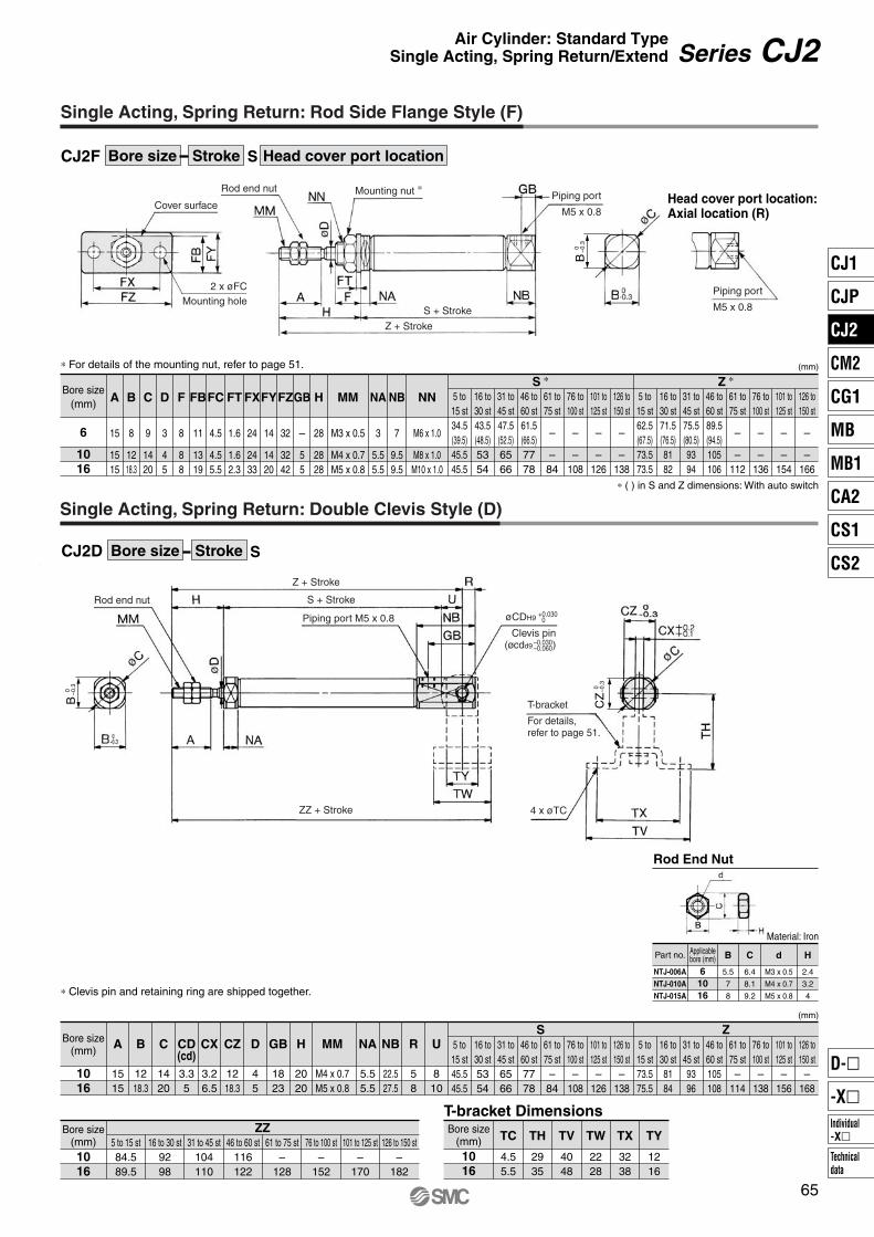
16
CDJ2 L 16 45With auto switch
CJ2
Spring return
Spring extend Bore size6
1016
6 mm
10 mm
16 mm
Mounting styleBLFD
Basic style
Axial foot style
Rod side flange style
Double clevis style (Except ø6)
With auto switch(Built-in magnet)
Applicable Auto Switch/Refer to pages 1263 to 1371 for further information on auto switches.
Built-in Magnet Cylinder Model
CDJ2B16-60S-A
CDJ2B10-45S-BExample
Rail mounting style
Band mounting style
Suffix the symbol “-A” (Rail mounting style) or “-B” (Band mounting style) to the end of part number for cylinder with auto switch.
∗ For rail mounting style, screws and nuts for 2 pcs. switches come with the rail.
∗ Refer to page 123 for switch mounting brackets.L 45
Cylinder standard stroke (mm)Refer to the standard stroke table on page 61.
ActionST
Single acting, Spring return
Single acting, Spring extend
S
S M9BW
Head cover port location
Nil
Sn
2 pcs.
1 pc.
“n” pcs.
Number of auto switches
NilR
—
Axial
ø6
Perpendicular to axis
Axial
ø10, ø16Bore size
(mm)Symbol
A96
——
A93A90
C73CC80C
—
M9N—
M9P—
M9B—
H7CM9NW
—M9PW
—M9BW
—H7BAH7NF
—
A72A73—
A80A73CA80CA79W
—F7NV
—F7PV
—F7BVJ79C
—F7NWV
———
F7BWVF7BAV
—
A76H
A72HA73H
—A80H
———
—F79—
F7P—
J79——
F79W—
F7PW—
J79WF7BAF79F
Made to OrderRefer to page 61 for details.
∗ For configuration, refer to page 43.∗ Single acting, Spring return (S), Clevis style is
available only for 90° to the axis. ∗ Not applicable to single acting, spring extend (T).
—
200 V
100 V
100 V or less—
24 V or less—
DC
24 V
24 V
5 V
—
12 V
—
5 V, 12 V
12 V
5 V, 12 V
12 V
5 V, 12 V
AC
—
—
Yes
Yes
YesNo
NoYes
Grommet
Grommet
Grommet
Connector
Connector
Grommet
3-wire(NPN equivalent)
2-wire
3-wire (NPN)
4-wire (NPN)
3-wire (NPN)
3-wire (PNP)
3-wire (PNP)
2-wire
2-wire
Relay,PLC
Relay,PLC
IC circuit
IC circuit
IC circuit
IC circuit
IC circuit
IC circuit
(Example) M9NW(Example) M9NWM(Example) M9NWL(Example) M9NWZ(Example) H7CN
∗ Since there are other applicable auto switches than listed, refer to page 123 for details.∗ For details about auto switches with pre-wired connector, refer to pages 1328 and 1329.∗ Band mounting style is not available for D-A9�V�/M9�V�/M9�WV� and D-M9�A(V)L types.
∗ Solid state auto switches marked with “�” are produced upon receipt of order.∗ D-A9�/M9�/M9�W/A7��/A80�/F7��/J7�� auto switches are shipped together (not assembled). (However, when D-A9�/M9�/M9�W types are selected,
only auto switch mounting brackets are assembled before being shipped.)∗ When D-A9�(V)/M9�(V)/M9�W(V) types are mounted on a ø10 or ø16 rail, order auto switch mounting brackets separately. Refer to page 123 for details.
60
Air Cylinder: Standard TypeSingle Acting, Spring Return/Extend
Series CJ2ø6, ø10, ø16
How to Order
Auto switch∗ For the applicable auto switch
model, refer to the table below.∗ If a built-in magnet cylinder without
an auto switch is required, refer to the model of built-in magnet cylinder.
Type Special function Electricalentry Ind
icator
light
Ree
d s
wit
chS
olid
sta
te s
wit
ch
Diagnostic indication(2-color indication)
Water resistant (2-color indication)With diagnostic output (2-color indication)
Diagnostic indication (2-color indication)
Wiring(Output)
Load voltage Lead wire length (m)0.5(Nil)
3(L)
1(M)
5(Z)
None(N)
Applicable loadAuto switch model
Band mounting(ø6, ø10, ø16)
Rail mounting (ø10, ø16)
Perpendicular In-line
Pre-wired connector
∗ Lead wire length symbols: 0.5 m········· 1 m········· 3 m········· 5 m········· None·········
NilMLZN
P0015-P0124-E.qxd 08.10.2 4:00 PM Page 60

106 16Bore size (mm)
Action
Fluid
Proof pressure
Maximum operating pressure
Minimum operating pressure
Ambient and fluid temperature
Cushion
Lubrication
Stroke length tolerance
Piston speed
Allowable kinetic energy
50 to 750 mm/s
Specifications
Single acting, Spring return/Single acting, Spring extend
Air
1 MPa
0.7 MPa
Without auto switch: –10°C to 70°C, With auto switch: –10°C to 60°C ∗
Rubber bumper/Air cushion
Not required (Non-lube)+1.0
0
∗ No freezing
(mm)
0.2 MPa
0.25 MPa
Standard Stroke (N)Spring Reaction ForceBore size (mm)
6
10
16
Standard stroke
15, 30, 45, 60
15, 30, 45, 60
15, 30, 45, 60, 75, 100, 125, 150
Bore size(mm)
61016
Primary
Spring reaction force (N)
Secondary
3.72
6.86
14.2
1.77
3.53
6.86∗ Manufacture of intermediate strokes at 1 mm intervals
is possible. (Spacers are not used.)
—XA�—XC22
—XC51
Change of rod end shape
Fluororubber seals
With hose nipple
Symbol Specifications
Spring extend
Spring return
JIS SymbolSingle acting, Spring return
Single acting,Spring extend
• Minimum stroke for auto switch mounting• Proper auto switch mounting position (detection at stroke end) and mounting height• Operating range• Switch mounting bracket part no.
Refer to pages 117 to 123 for cylinders with auto switches.
0.012J 0.035J 0.090J
0.15 MPa
0.15 MPa
Rubber bumper
Air cushion
Spring with primary mounting load
Spring with secondary mounting load
When the spring is set in the cylinder
When the spring is contracted by applying air
IN OUT
61
Made to Order Specifications(For details, refer to pages 1373 to 1498.)
Series CJ2Air Cylinder: Standard TypeSingle Acting, Spring Return/Extend
CJ1
CJP
CJ2
CM2
CG1
MB
MB1
CA2
CS1
CS2
Individual-X�
D-�
-X�
Technicaldata
P0015-P0124-E.qxd 08.10.2 4:00 PM Page 61

Mass/Spring Return (S)
Mounting Bracket Part No.
Mounting Style and Accessory/For details, refer to page 51.
(g)
Bore size (mm)
Basicmass ∗
Mountingbracketmass
Bore size (mm)
Basicmass ∗
Mountingbracketmass
15 stroke
30 stroke
45 stroke
60 stroke
75 stroke
100 stroke
125 stroke
150 stroke
6
11
16
18
23
8
5
10
28
35
44
53
8
5
4
16
63
80
102
124
145
188
224
250
20
15
10
Mass/Spring Extend (T) (g)
15 stroke
30 stroke
45 stroke
60 stroke
75 stroke
100 stroke
125 stroke
150 stroke
6
17
21
23
27
8
5
10
28
34
43
51
8
5
4
16
64
80
100
121
140
178
212
236
20
15
10
Mounting bracket6
CJ-L006B
CJ-F006B
—
10CJ-L010B
CJ-F010B
CJ-T010B
Bore size (mm)16
CJ-L016B
CJ-F016B
CJ-T016B∗ T-bracket is used with double clevis (D).
SpecificationsSingle acting: Spring return Single acting: Spring extend
6, 10, 16
0.7 MPa
0.15 MPa
Rubber bumper (Standard equipment)
Same as standard type. (Refer to page 61.)
Mountable (Band mounting style)
0.25 MPa0.2 MPa
Mounting
Be sure to read before handling.Refer to front matters 54 and 55 for Safety Instructions and pages 3 to 11 for Actuator and Auto Switch Precautions.
Specific Product Precautions
Copper and Fluorine-free Air Cylinder (For CRT manufacturing process)
ø6
ø10, ø16
Basic style, Axial foot style, Rod side flange style,Double clevis style (Except ø6)
62
Series CJ2
Axial foot style
Rod side flange style
Double clevis style (With pin) *
∗ Mounting nut and rod end nut are included in the basic mass.∗∗ Mounting nut is not attached to the double clevis style, so the mounting
nut mass is already subtracted.Calculation: (Example) CJ2L10-45S
• Basic mass ······················· 44 (ø10-45 stroke)• Mounting bracket mass····· 8 (Axial foot style)
44 + 8 = 52 g
Axial foot style
Rod side flange style
Double clevis style (With pin)*
∗ Mounting nut and rod end nut are included in the basic mass.∗∗ Mounting nut is not attached to the double clevis style, so the mounting
nut mass is already subtracted.Calculation: (Example) CJ2L10-45T
• Basic mass ······················· 43 (ø10-45 stroke)• Mounting bracket mass····· 8 (Axial foot style)
43 + 8 = 51 g
Foot bracketFlange bracketT-bracket ∗
Mounting
Sta
ndar
deq
uipm
ent
Opt
ion
Mounting nut
Rod end nut
Clevis pin
Single knuckle joint
Double knuckle joint ∗
T-bracket
Basicstyle
Axial footstyle
Rod sideflange style
Double ∗clevis style
∗ Pin and retaining ring are shipped together with double clevis and double knuckle joint. For the attached bracket mass, refer to page 44.
Theoretical OutputRefer to the “Single acting, Spring return cylinder” in Theoretical Output 1 of Technical data 3 on page 1573. In the case of the spring extend style, the force at OUT side will be the ending force of the spring return, and that at the IN side will be the amount of the IN side force of the double acting style cylinder from which the beginning force of the spring return has been subtracted.
Caution1. During installation, secure the rod cover and tighten by applying an
appropriate tightening force to the retaining nut or to the rod cover body. If the head cover is secured or the head cover is tightened, the cover could rotate, leading to the deviation.
2. Tighten the retaining screws to an appropriate tightening torque within the range given below.ø6: 2.1 to 2.5 N·m, ø10: 5.9 to 6.4 N·m, ø16: 10.8 to 11.8 N·m
3. In the case of a single acting cylinder, do not operate it in such a way that a load would be applied during the retraction of the piston rod of the spring return style, or during the extension of the piston rod of the spring extend style. The spring that is built into the cylinder provides only enough force to retract the piton rod. Thus, if a load is applied, the piston rod will not be able to retract to the end of the stroke.
4. In the case of a single acting cylinder, a breather hole is provided in the cover surface. Make sure not to block this hole during installation, as this could lead to a malfunction.
5. To remove and install the retaining ring for the knuckle pin or the clevis pin, use an appropriate pair of pliers (tool for installing a type C retaining ring). In particular, use a pair of ultra-mini pliers for removing and installing the retaining ring on the ø10 cylinder.
6. In the case of auto switch rail mounting style, do not remove the rail that is mounted. Because retaining screws extend into the cylinder, this could lead to an air leak.
Mounting style Bore size Stroke Action Head coverport location20-CJ2
Copper and fluorine-free
Eliminates the effects by copper based ions and fluorine based resins, etc. over the color cathode ray tube.Making copper based materials into electroless nickel plated treatment or changing them to the non-copper materials in order to prevent copper ions from generating.
Action
Bore size (mm)
Maximum operating pressure
Cushion
Standard stroke (mm)
Auto switch
Minimum operatingpressure
Mounting
P0015-P0124-E.qxd 08.10.2 4:00 PM Page 62

CJ2�6 Piston/Head cover
CJ2�6 Piston/Rod cover
Single acting, Spring extend
Component PartsNo.
12345678
Description Material
Aluminum alloy
Aluminum alloy
Stainless steel
Stainless steel
Brass
Brass
Piano wire
Brass
Note
Anodized
Anodized
Zinc chromated
Rod cover
Head cover
Cylinder tube
Piston rod
Piston A
Piston B
Return spring
Spring seat
No.
910111213141516
Description Material
Aluminum alloy
Urethane
Brass
Rolled steel
NBR
NBR
NBR
NBR
Note
Clear anodized (ø6 spring extend)
Nickel plated
Nickel plated
Seal retainer
Bumper
Mounting nut
Rod end nut
Piston seal
Rod seal
Tube gasket
Piston gasket
63
Series CJ2Air Cylinder: Standard TypeSingle Acting, Spring Return/Extend
Construction (Not able to disassemble)
Single acting, Spring return
CJ1
CJP
CJ2
CM2
CG1
MB
MB1
CA2
CS1
CS2
Individual-X�
D-�
-X�
Technicaldata
P0015-P0124-E.qxd 08.10.2 4:00 PM Page 63

Bore size(mm)
6
1016
15
1515
A
8
1218.3
9
1420
3
45
8
88
–
55
28
2828
M3 x 0.5
M4 x 0.7M5 x 0.8
3
5.55.5
7
9.59.5
6
810
M6 x 1.0
M8 x 1.0M10 x 1.0
B C D F GB H MM NA NB ND h8 NN
34.5(39.5)45.545.5
5 to15 st
16 to30 st
31 to45 st
46 to60 st
61 to75 st
S ∗76 to100 st
101 to125 st
126 to150 st
5 to15 st
16 to30 st
31 to45 st
46 to60 st
61 to75 st
Z ∗76 to100 st
101 to125 st
126 to150 st
43.5(48.5)5354
47.5(52.5)6566
61.5(66.5)7778
–
–84
–
–108
–
–126
–
–138
62.5(67.5)73.573.5
71.5(76.5)8182
75.5(80.5)9394
89.5(94.5)105106
–
–112
–
–136
–
–154
–
–166
(mm)∗ For details of the mounting nut, refer to page 51.
∗ ( ) in S and Z dimensions: With auto switch
Bore size(mm)
6
1016
15
1515
A
8
1218.3
9
1420
3
45
8
88
–
55
28
2828
13
1523
4.5
4.55.5
9
914
1.6
1.62.3
24
2433
16.5
16.525
32
3242
M3 x 0.5
M4 x 0.7M5 x 0.8
3
5.55.5
7
9.59.5
M6 x 1.0
M8 x 1.0M10 x 1.0
5
56
7
79
B C D F GB H LB LC LH LT LX LY LZ MM NA NB NN X Y
34.5(39.5)45.545.5
5 to 15 st
16 to 30 st
31 to 45 st
46 to 60 st
61 to 75 st
S ∗76 to 100 st
101 to 125 st
126 to 150 st
5 to 15 st
16 to 30 st
31 to 45 st
46 to 60 st
61 to 75 st
Z ∗76 to 100 st
101 to 125 st
126 to 150 st
43.5(48.5)5354
47.5(52.5)6566
61.5(66.5)7778
–
–84
–
–108
–
–126
–
–138
62.5(67.5)73.573.5
71.5(76.5)8182
75.5(80.5)9394
89.5(94.5)105106
–
–112
–
–136
–
–154
–
–166
(mm)∗ For details of the mounting nut, refer to page 51.
∗ ( ) in S and Z dimensions: With auto switch
Part no.
NTJ-006ANTJ-010ANTJ-015A
Applicablebore (mm)
61016
B
5.5
7
8
C
6.4
8.1
9.2
d
M3 x 0.5
M4 x 0.7
M5 x 0.8
H
2.4
3.2
4
Material: Iron
B0 –0
.3
B0 –0
.3
64
Series CJ2
Single Acting, Spring Return: Basic Style (B)
CJ2B S Head cover port locationBore size Stroke
0–0.018
0–0.022 0–0.022
Single Acting, Spring Return: Axial Foot Style (L)
CJ2L S Head cover port locationBore size Stroke
Rod End Nut
Mounting nut ∗Rod end nut
S + StrokeZ + Stroke
Piping port
M5 x 0.8
Piping port
M5 x 0.8
Head cover port location:Axial location (R)
Mounting nut ∗Rod end nut
S + Stroke
Z + Stroke
Piping portM5 x 0.8
Piping port
M5 x 0.8
Head cover port location:Axial location (R)Cover surface
2 x øLC
Mounting hole
P0015-P0124-E.qxd 08.10.2 4:01 PM Page 64
Bore size(mm)
6
1016
15
1515
A
8
1218.3
B
9
1420
C
3
45
D
8
88
F
11
1319
FB
24
2433
FX
14
1420
FY
32
3242
FZ
–
55
GB
28
2828
H
M3 x 0.5
M4 x 0.7M5 x 0.8
MM
3
5.55.5
NA
7
9.59.5
NB
M6 x 1.0
M8 x 1.0M10 x 1.0
NN
4.5
4.55.5
FC
1.6
1.62.3
FT
34.5(39.5)45.545.5
5 to15 st
16 to30 st
31 to45 st
46 to60 st
61 to75 st
S ∗76 to100 st
101 to125 st
126 to150 st
5 to15 st
16 to30 st
31 to45 st
46 to60 st
61 to75 st
Z ∗76 to100 st
101 to125 st
126 to150 st
43.5(48.5)5354
47.5(52.5)6566
61.5(66.5)7778
–
–84
–
–108
–
–126
–
–138
62.5(67.5)73.573.5
71.5(76.5)8182
75.5(80.5)9394
89.5(94.5)105106
–
–112
–
–136
–
–154
–
–166
(mm)
∗ ( ) in S and Z dimensions: With auto switch
Bore size(mm)
1016
Bore size(mm)1016
Bore size(mm)1016
TC
4.55.5
TH
2935
TV
4048
TW
2228
TX
3238
TY
1216
1515
A
1218.3
B
1420
C
3.35
CD(cd)
3.26.5
CX
1218.3
CZ
45
D
1823
GB
2020
H
M4 x 0.7M5 x 0.8
MM
5.55.5
NA
22.527.5
NB
58
R
810
U
45.545.5
5 to15 st
16 to30 st
31 to45 st
46 to60 st
61 to75 st
S76 to100 st
101 to125 st
126 to150 st
5 to15 st
16 to30 st
31 to45 st
46 to60 st
61 to75 st
Z76 to100 st
101 to125 st
126 to150 st
5354
6566
7778
–84
–108
–126
–138
73.575.5
8184
9396
105108
–114
–138
–156
–168
(mm)
∗ Clevis pin and retaining ring are shipped together.
Part no.
NTJ-006ANTJ-010ANTJ-015A
Applicablebore (mm)
61016
B
5.5
7
8
C
6.4
8.1
9.2
d
M3 x 0.5
M4 x 0.7
M5 x 0.8
H
2.4
3.2
4
Material: Iron
ZZ5 to 15 st84.589.5
16 to 30 st9298
31 to 45 st104110
46 to 60 st116122
61 to 75 st–
128
76 to 100 st–
152
101 to 125 st–
170
126 to 150 st–
182
T-bracket Dimensions
B0 –0
.3
CZ
0 –0.3
B0 –0
.3
65
Series CJ2Air Cylinder: Standard TypeSingle Acting, Spring Return/Extend
Single Acting, Spring Return: Rod Side Flange Style (F)
CJ2F S Head cover port locationBore size Stroke
∗ For details of the mounting nut, refer to page 51.
Single Acting, Spring Return: Double Clevis Style (D)
CJ2D SBore size Stroke
Rod End Nut
Mounting nut ∗Rod end nutPiping port
M5 x 0.8
Piping port
M5 x 0.8
Head cover port location:Axial location (R)
Cover surface
2 x øFCMounting hole
S + Stroke
Z + Stroke
Rod end nut S + Stroke
Z + Stroke
ZZ + Stroke
Piping port M5 x 0.8
T-bracket
For details, refer to page 51.
øCDH9
Clevis pin(øcdd9 )
4 x øTC
+0.030 0
–0.030 –0.060
CJ1
CJP
CJ2
CM2
CG1
MB
MB1
CA2
CS1
CS2
Individual-X�
D-�
-X�
Technicaldata
P0015-P0124-E.qxd 08.10.2 4:01 PM Page 65

CJ2B6
CJ2B10, 16
CJ2L6
CJ2L10, 16
∗ ( ) in S and Z dimensions: With auto switch
∗ For details of the mounting nut, refer to page 51. (mm)
Bore size(mm)
6
1016
A
15
1515
12
1218.3
B C
14
1420
D
3
45
F
8
88
GA
14.5
88
H
28
2828
MM
M3 x 0.5
M4 x 0.7M5 x 0.8
NN
M6 x 1.0
M8 x 1.0M10 x 1.0
NA
16
12.512.5
NB
3
5.55.5
ND h8 T
3
––
S ∗5 to15 st46.5(51.5)48.548.5
6
810 0
–0.022
0 –0.018
0 –0.022
16 to30 st55.5(60.5)5657
31 to45 st59.5(64.5)6869
46 to60 st73.5(78.5)8081
61 to75 st
–
–87
76 to100 st
–
–111
101 to125 st
–
–129
126 to150 st
5 to15 st
16 to30 st
31 to45 st
46 to60 st
61 to75 st
76 to100 st
101 to125 st
126 to150 st
–
–141
–
–115
–
–139
–
–157
–
–169
Z ∗
74.5(79.5)76.576.5
83.5(88.5)8485
87.5(92.5)9697
101.5 (106.5)108109
∗ For details of the mounting nut, refer to page 51. (mm)
Bore size(mm)
6
1016
A
15
1515
B
12
1218.3
C
14
1420
D
3
45
F
8
88
GA
14.5
88
H
28
2828
LB
15
1523
LC
4.5
4.55.5
LH
9
914
LT
1.6
1.62.3
LX
24
2433
LY
16.5
16.525
LZ
32
3242
MM
M3 x 0.5
M4 x 0.7M5 x 0.8
NA
16
12.512.5
NB
3
5.55.5
NN
M6 x 1.0
M8 x 1.0M10 x 1.0
T
3
––
X
5
56
Y
7
79
S ∗ Z ∗5 to15 st
16 to30 st
31 to45 st
46 to60 st
61 to75 st
76 to100 st
101 to125 st
126 to150 st
5 to15 st
16 to30 st
31 to45 st
46 to60 st
61 to75 st
76 to100 st
101 to125 st
126 to150 st
46.5(51.5)
48.548.5
55.5(60.5)
5657
59.5(64.5)
6869
73.5(78.5)8081
–
–87
–
–111
–
–129
–
–141
–
–115
–
–139
–
–157
–
–169
76.576.5
8485
9697
108109
74.5(79.5)
83.5(88.5)
87.5(92.5)
101.5 (106.5)
Part no.
NTJ-006ANTJ-010ANTJ-015A
Applicablebore (mm)
61016
B
5.5
7
8
C
6.4
8.1
9.2
d
M3 x 0.5
M4 x 0.7
M5 x 0.8
H
2.4
3.2
4
Material: Iron
∗ ( ) in S and Z dimensions: With auto switch
B0 -0.3
80 -0.3
B0 -0.3
B0 -0.3
B0 –0
.3
80 -0.3
66
Series CJ2
Single Acting, Spring Extend: Basic Style (B)
CJ2B TBore size Stroke
Single Acting, Spring Extend: Axial Foot Style (L)
CJ2L TBore size Stroke
Rod End Nut
Mounting nut ∗
Mounting nut ∗
Rod end nut
Rod end nut
Piping port M5 x 0.8
Piping port M5 x 0.8
H + Stroke S + Stroke
H + Stroke S + Stroke
Z + 2 x Stroke
Z + 2 x Stroke
Rod end nut
Mounting nut ∗
Mounting nut ∗
Piping port M5 x 0.8
Piping port M5 x 0.8
H + Stroke S + StrokeZ + 2 x Stroke
H + Stroke S + Stroke
Z + 2 x Stroke
Cover surface
Cover surface
Cover surface
Rod cover side Head cover side
2 x øLCMounting hole
P0015-P0124-E.qxd 08.10.2 4:01 PM Page 66

CJ2F6
CJ2F10, 16
∗ ( ) in S and Z dimensions: With auto switch
∗ For details of the mounting nut, refer to page 51.(mm)
Bore size(mm)
6
1016
15
1515
A B
12
1218.3
C
14
1420
D
3
45
F
8
88
FB
13
1319
FC
4.5
4.55.5
FT
1.6
1.62.3
FX
24
2433
FY
14
1420
FZ
32
3242
GA
14.5
88
28
2828
H MM
M3 x 0.5
M4 x 0.7M5 x 0.8
NA
16
12.512.5
NB
3
5.55.5
NN
M6 x 1.0
M8 x 1.0M10 x 1.0
T
3
––
S ∗5 to
15 st46.5(51.5)48.548.5
16 to30 st55.5(60.5)5657
31 to45 st59.5(64.5)6869
46 to60 st73.5(78.5)8081
61 to75 st
–
–87
76 to100 st
–
–111
101 to125 st
–
–129
126 to150 st
5 to15 st
16 to30 st
31 to45 st
46 to60 st
61 to75 st
76 to100 st
101 to125 st
126 to150 st
–
–141
74.5(79.5)76.576.5
83.5(88.5)8485
87.5(92.5)9697
101.5(106.5)108109
–
–115
–
–139
–
–157
–
–169
Z ∗
NTJ-006ANTJ-010ANTJ-015A
61016
B
5.5
7
8
C
6.4
8.1
9.2
d
M3 x 0.5
M4 x 0.7
M5 x 0.8
H
2.4
3.2
4
Material: Iron
126 to150 st–
179
(mm)
Bore size(mm)
1016
A
1515
B
1218.3
C
1420
CD(cd)3.35
CX
3.26.5
CZ
1218.3
D
45
GA
88
H
2828
MM
M4 x 0.7M5 x 0.8
NA
12.512.5
NB
18.523.5
R
58
U
810
S5 to15 st48.548.5
16 to30 st5657
31 to45 st6869
46 to60 st8081
61 to75 st–87
76 to100 st–
111
101 to125 st–
129
126 to150 st–
141
Z5 to15 st84.586.5
16 to30 st9295
31 to45 st104107
46 to60 st116119
61 to75 st–
125
76 to100 st–
149
101 to125 st–
167
TY
1216
T-bracket DimensionsBore size
(mm)
1016
TC
4.55.5
TH
2935
TV
4048
TW
2228
TX
3238
126 to 150 st–
193
Bore size(mm)
1016
ZZ5 to 15 st
95.5100.5
16 to 30 st103109
31 to 45 st115121
46 to 60 st127133
61 to 75 st–
139
76 to 100 st–
163
101 to 125 st–
181
(mm)
∗ Clevis pin and retaining ring are shipped together.
BB
8
B0 –0
.3 CZ
0 –0.3
0 –0.3
0 –0.3
0 –0.3
67
Series CJ2Air Cylinder: Standard TypeSingle Acting, Spring Return/Extend
Single Acting, Spring Extend: Rod Side Flange Style (F)
CJ2F TBore size Stroke
Rod End Nut
Part no. Applicablebore (mm)
Single Acting, Spring Extend: Double Clevis Style (D)
CJ2D TBore size Stroke
Mounting nut ∗
Mounting nut ∗
2 x øFC
Mounting hole
Rod end nut
Rod end nut
Piping port M5 x 0.8
Piping port M5 x 0.8
H + Stroke S + Stroke
Z + 2 x Stroke
H + Stroke S + Stroke
Z + 2 x Stroke
Cover surface
Cover surface
2 x øFC
Mounting hole
Rod cover side Head cover side
Rod end nut
Piping port M5 x 0.8
H + Stroke S + Stroke
Z + 2 x Stroke
ZZ + 2 x Stroke
T-bracket
For details, refer to page 51.
øCDH9
Clevis pin (øcdd9 )
+0.030 0
–0.030 –0.060
CJ1
CJP
CJ2
CM2
CG1
MB
MB1
CA2
CS1
CS2
Individual-X�
D-�
-X�
Technicaldata
P0015-P0124-E.qxd 08.10.2 4:01 PM Page 67

CJ2K L
CDJ2K L
16 60
16 60 M9BWWith auto switch
Mounting styleBLFD
Basic style
Axial foot style
Rod side flange style
Double clevis style
Bore size1016
10 mm
16 mm
Cylinder standard stroke (mm)Refer to the standard stroke table on page 69.
Nil
RPerpendicular to axis
Axial
Head cover port location
With auto switch(Built-in magnet)
Applicable Auto Switch/Refer to pages 1263 to 1371 for further information on auto switches.
ø10, ø16Nil
Sn
2 pcs.
1 pc.
“n” pcs.
Number of auto switches
Made to OrderRefer to page 69 for details.
—
200 V
100 V
100 V or less—
24 V or less—
Load voltage
DC
24 V
24 V
5 V
—
12 V
—
5 V, 12 V
12 V
5 V, 12 V
12 V
5 V, 12 V
AC
A96
——
A93A90
C73CC80C
—
M9N—
M9P—
M9B—
H7CM9NW
—M9PW
—M9BW
—H7BAH7NF
—
A72A73—
A80A73CA80C
A79W ∗∗
—F7NV
—F7PV
—F7BVJ79C
—F7NWV
———
F7BWVF7BAV
—
A76H
A72HA73H
—A80H
———
—F79—
F7P—
J79——
F79W—
F7PW—
J79WF7BAF79F
—
—
CDJ2KB16-60-A
CDJ2KB10-45-BExample
Rail mounting style
Band mounting style
∗ For rail mounting style, screws and nuts for 2 pcs switches come with the rail.
∗ Refer to page 123 for switch mounting brackets.
Auto switch∗ For the applicable auto switch
model, refer to the table below.∗ If a built-in magnet cylinder without
an auto switch is required, refer to the model of built-in magnet cylinder.
Yes
Yes
YesNo
NoYes
Grommet
Grommet
Grommet
Connector
Connector
Grommet
3-wire(NPN equivalent)
2-wire
3-wire (NPN)
4-wire (NPN)
3-wire (NPN)
3-wire (PNP)
3-wire (PNP)
2-wire
2-wire
Relay,PLC
Relay,PLC
IC circuit
IC circuit
IC circuit
IC circuit
IC circuit
IC circuit
(Example) M9NW(Example) M9NWM(Example) M9NWL(Example) M9NWZ(Example) H7CN
∗ Since there are other applicable auto switches than listed, refer to page 123 for details. ∗ For details about auto switches with pre-wired connector, refer to pages 1328 and 1329. ∗ Band mounting style is not available for D-A9�V/M9�V/M9�WV and D-M9�A(V)L types. ∗∗ “D-A79W” cannot be mounted on bore size ø10 cylinder with air cushion.
∗ Solid state auto switches marked with “�” are produced upon receipt of order.∗ D-A9�/M9�/M9�W/A7��/A80�/F7��/J7�� auto switches are shipped together (not assembled). (However, when D-A9�/M9�/M9�W types are selected,
only auto switch mounting brackets are assembled before being shipped.)∗ When D-A9�(V)/M9�(V)/M9�W(V) types are mounted on a ø10 or ø16 rail, order auto switch mounting brackets separately. Refer to page 123 for details.
68
Air Cylinder: Non-rotating Rod TypeDouble Acting, Single Rod
Series CJ2Kø10, ø16
How to Order
Built-in Magnet Cylinder ModelSuffix the symbol “-A” (Rail mounting style) or “-B” (Band mounting style) to the end of part number for cylinder with auto switch.
Symbol
Bore size(mm)
∗For configuration, refer to page 69.∗ Double clevis is only available for
being perpendicular to axis.
Type Special function Electricalentry
Indica
tor lig
ht
Ree
d s
wit
chS
olid
sta
te s
wit
ch
Diagnostic indication(2-color indication)
Water resistant (2-color indication)With diagnostic output (2-color indication)
Diagnostic indication (2-color indication)
Wiring(Output)
Lead wire length (m)0.5(Nil)
3(L)
1(M)
5(Z)
None(N)
Applicable loadAuto switch model
Bandmounting
Rail mountingPerpendicular In-line
Pre-wired connector
∗ Lead wire length symbols: 0.5 m········· 1 m········· 3 m········· 5 m········· None·········
NilMLZN
P0015-P0124-E.qxd 08.10.2 4:01 PM Page 68

10 16Bore size (mm)
Action
Fluid
Proof pressure
Maximum operating pressure
Minimum operating pressure
Ambient and fluid temperature
Cushion
Lubrication
Stroke length tolerance
Rod non-rotating accuracy
Piston speed
Allowable kinetic energy
50 to 750 mm/s
0.090 J0.035 J
Specifications
Air
1 MPa
0.7 MPa
0.06 MPa
Without auto switch: –10°C to 70°C, With auto switch: –10°C to 60°C
Rubber bumper
Not required (Non-lube) +1.0
0
∗ No freezing
(mm)
Double acting, Single rod
Standard StrokeBore size (mm)
10
16
Standard stroke
±1.5° ±1°
15, 30, 45, 60, 75, 100, 125, 150
15, 30, 45, 60, 75, 100, 125, 150, 175, 200
∗ Pin and retaining ring are shipped together with double clevis and double knuckle joint.
Mounting Style and Accessory/For details, refer to page 51.
∗ Manufacture of intermediate strokes at 1 mm intervals is possible. (Spacers are not used.)
—XA�—XC3
—XC10
—XC22
—XC51
Change of rod end shape
Special port location
Dual stroke cylinder/Double rod type
Fluororubber seals
With hose nipple
Symbol Specifications
∗ T-bracket is used with double clevis (D).
CJ-L016B
CJ-F016B
CJ-T010B
CJK-L016B
CJK-F016B
CJ-T016B
10 16
Mounting Bracket Part No.
Head Cover Port Location
Either perpendicular to the cylinder axis or in-line with the cylinder axis is available for basic style.
Axial Perpendicular
JIS SymbolDouble acting, Single rod
• Minimum stroke for auto switch mounting• Proper auto switch mounting position (detection at stroke end) and mounting height• Operating range• Switch mounting bracket part no.
Refer to pages 117 to 123 for cylinders with auto switches.
69
Made to Order Specifications(For details, refer to pages 1373 to 1498.)
Series CJ2KAir Cylinder: Non-rotating Rod TypeDouble Acting, Single Rod
A cylinder which rod does not rotate because of the hexagonal rod shape.
Non-rotating accuracyø10: ±1.5°, ø16: ±1°Can operate without lubrication.
Mounting style
Mounting nut
Rod end nut
Clevis pin
Single knuckle joint
Double knuckle joint ∗
T-bracket
Basicstyle
Axialfoot style
Rod sideflange style
Double clevis ∗ style
Sta
ndar
deq
uipm
ent
Opt
ion
Mounting bracket
Foot bracket
Flange bracket
T-bracket ∗
Bore size (mm)
CJ1
CJP
CJ2
CM2
CG1
MB
MB1
CA2
CS1
CS2
Individual-X�
D-�
-X�
Technicaldata
P0015-P0124-E.qxd 08.10.2 4:01 PM Page 69

4. To screw a bracket onto the threaded portion at the tip of the piston rod, make sure to retract the piston rod entirely, and place a wrench over the flat portion of the rod that protrudes. To tighten, take precautions to prevent the tightening torque from being applied to the non-rotating guide.
5. To remove and install the retaining ring for the knuckle pin or the clevis pin, use an appropriate pair of pliers (tool for installing a type C retaining ring). In particular, use a pair of ultra-mini pliers for removing and installing the retaining ring on the ø10 cylinder.
6. In the case of auto switch rail mounting style, do not remove the rail that is mounted. Because retaining screws extend into the cylinder, this could lead to an air leak.
Allowable rotational torque (N·m)ø100.02
ø160.04
Copper and Fluorine-free Air Cylinder (For CRT manufacturing process)
Construction (Not able to disassemble)
Eliminates the effects by copper based ions and fluorine based resins, etc. over the color cathode ray tube.Making copper based materials into electroless nickel plated treatment or changing them to the non-copper materials in order to prevent copper ions from generating.
Basic style, Axial foot style, Rod side flange style, Double clevis style
SpecificationsAction
Maximum operating pressure
Minimum operating pressure
Cushion
Rod non-rotatingaccuracy
Standard stroke (mm)
Auto switch
Mounting
Double acting, Single rod
0.7 MPa
0.06 MPa
Rubber bumper (Standard equipment)
±1.5°±1°
Same as standard type. (Refer to page 69.)
Mountable (Band mounting style)
ø10ø16
Component PartsNo.
123456
Description Material
Aluminum alloy
Aluminum alloy
Stainless steel
Stainless steel
Brass
Brass
Note
Anodized
Anodized
Nickel plated
Rod cover
Head cover
Cylinder tube
Piston rod
Piston
Mounting nut
No.
789101112
Description Material
Rolled steel
Urethane
NBR
NBR
NBR
NBR
Note
Nickel platedRod end nut
Bumper
Piston seal
Rod seal
Tube gasket
Piston gasket
Mass (g)
10
24
4
20
15
4
16
55
6.5
20
15
10Caution on Handling
Be sure to read before handling.Refer to front matters 54 and 55 for Safety Instructions and pages 3 to 11 for Actuator and Auto Switch Precautions.
Specific Product Precautions
70
Series CJ2K
Caution1. During installation, secure the rod cover and tighten by applying an
appropriate tightening force to the retaining but or to the rod cover body.If the head cover is secured or the head cover is tightened, the cover could rotate, leading to the deviation.
2. Tighten the retaining screws to an appropriate tightening torque within the range given below.ø10: 10.8 to 11.8 N·m, ø16: 20 to 21 N·m
3. In the case of a non-rotating cylinder, do not operate it in such a way that rotational torque would be applied to the piston rod. If rotational torque is applied, the non-rotating guide will become deformed, thus affecting the non-rotating accuracy.
Bore size (mm)
Basic mass ∗
Additional mass per each 15 mm of stroke
Mountingbracketmass
Axial foot style
Rod side flange style
Double clevis style (With pin) ∗
∗ Mounting nut and rod end nut are included in the basic mass.∗∗ Mounting nut is not attached to the double clevis style, so the mounting nut
mass is already subtracted.Calculation: (Example) CJ2KL10-45
• Basic mass ·························· 24 (ø10)• Additional mass ··················· 4/15 stroke• Cylinder stroke ···················· 45 stroke• Mounting bracket mass ······· 20 (Axial foot style)24 + 4/15 x 45 + 20 = 56 g
20-CJ2K
Copper and fluorine-free
Bore sizeMounting style Stroke Head coverport location
Rod section
P0015-P0124-E.qxd 08.10.2 4:01 PM Page 70

∗ Refer to page 51 for details of the mounting nut. (SNJ-016B for ø10, SNKJ-016B for ø16) (mm)
Bore size (mm)
1016
A15
15
BA15
18.3
BB12
18.3
CA17
20
CB14
20
F8
8
GA8
8
GB5
5
H28
28
KA4.2
5.2
MMM4 x 0.7
M5 x 0.8
NA12.5
12.5
NB9.5
9.5
NDh8 NNM10 x 1.0
M12 x 1.0
S46
47
Z74
75
10 0–0.022
12 0–0.027
Part no. B C d H
7 8.1 M4 x 0.7 3.28 9.2 M5 x 0.8 4
NTJ-010ANTJ-015A
Applicablebore (mm)
1016
Material: Iron
∗ Refer to page 51 for details of the mounting nut. (SNJ-016B for ø10, SNKJ-016B for ø16) (mm)
Bore size (mm)
1016
A15
15
BA15
18.3
BB12
18.3
CA17
20
CB14
20
F8
8
GA8
8
GB5
5
H28
28
KA4.2
5.2
LB21.5
23
LC5.5
5.5
LH14
14
LT2.3
2.3
LX33
33
LY25
25
LZ42
42
MMM4 x 0.7
M5 x 0.8
NA12.5
12.5
NB9.5
9.5
NNM10 x 1.0
M12 x 1.0
X6
6
Y9
9
S46
47
Z74
75
BA
0 –0.3
BB
0 -0.3
BA
0 -0.3
BB
0 -0.3
71
Series CJ2KAir Cylinder: Non-rotating Rod TypeDouble Acting, Single Rod
Basic Style (B)
CJ2KB Head cover port locationBore size Stroke
Axial Foot Style (L)
CJ2KL Head cover port locationBore size Stroke
Mounting nut ∗
Rod end nut
S + Stroke
Z + Stroke
Piping port 2 x M5 x 0.8Piping port M5 x 0.8
Head cover port location:Axial location (R)
Rod section
Head cover port location:Axial location (R)
Rod End Nut
Mounting nut ∗
Rod end nut
S + Stroke
Z + Stroke
Piping port M5 x 0.8Piping port 2 x M5 x 0.8Cover surface
2 x øLC
Mounting hole
Rod cover side
Rod section
CJ1
CJP
CJ2
CM2
CG1
MB
MB1
CA2
CS1
CS2
Individual-X�
D-�
-X�
Technicaldata
P0015-P0124-E.qxd 08.10.2 4:01 PM Page 71

(mm)
Bore size (mm)
1016
A15
15
BA15
18.3
BB12
18.3
CA17
20
CB14
20
F8
8
FB17.5
19
FC5.5
5.5
FT2.3
2.3
FX33
33
FY20
20
FZ42
42
GA8
8
GB5
5
H28
28
KA4.2
5.2
MMM4 x 0.7
M5 x 0.8
NA12.5
12.5
NB9.5
9.5
NNM10 x 1.0
M12 x 1.0
S46
47
Z74
75
∗ Refer to page 51 for details of the mounting nut. (SNJ-016B for ø10, SNKJ-016B for ø16)
Part no. B C d H
7 8.1 M4 x 0.7 3.28 9.2 M5 x 0.8 4
NTJ-010ANTJ-015A
Applicablebore (mm)
1016
Material: Iron
Bore size (mm)
1016
A15
15
BA15
18.3
BB12
18.3
CA17
20
CB14
20
CD(cd)3.3
5
CX3.2
6.5
GA8
8
GB18
23
H28
28
KA4.2
5.2
MMM4 x 0.7
M5 x 0.8
NA12.5
12.5
NB22.5
27.5
R5
8
S46
47
U8
10
Z82
85
ZZ93
99
T-bracket Dimensions (mm)
Bore size (mm)
1016
TC4.5
5.5
TH29
35
TV40
48
TW22
28
TX32
38
TY12
16
∗ Clevis pin and retaining ring are shipped together.
–0.3
BA
0 –0.3
BB
0
–0.3
BA
0
–0.3
BB
0
72
Series CJ2K
Rod Side Flange Style (F)
CJ2KF Head cover port locationBore size Stroke
Double Clevis Style (D)
CJ2KD Bore size Stroke
Rod End Nut
Head cover port location:Axial location (R)
Rod cover side
Mounting nut ∗
Rod end nut
S + StrokeZ + Stroke
Piping port 2 x M5 x 0.8 Piping port M5 x 0.8Cover surface
2 x øFCMounting hole
Rod section
Rod section
Rod end nut
T-bracket
For details, refer to page 51.
øCDH9
Clevis pin(øcdd9 )
+0.030 0
–0.030 –0.060
Z + Stroke
S + Stroke
Piping port 2 x M5 x 0.8
ZZ + Stroke
P0015-P0124-E.qxd 08.10.2 4:01 PM Page 72

M9BW
CJ2K L S
CDJ2K L S
16 45
16 45With auto switch
Mounting styleBLFD
Basic style
Axial foot style
Rod side flange style
Double clevis style
Bore size1016
10 mm
16 mm
Cylinder standard stroke (mm)Refer to the standard stroke table on page 74.
ActionST
Single acting, Spring return
Single acting, Spring extend
Head cover port locationWith auto switch(Built-in magnet)
Auto switch∗ For the applicable auto switch
model, refer to the table below.∗ If a built-in magnet cylinder
without an auto switch is required, refer to the model of built-in magnet cylinder.
Applicable Auto Switch/Refer to pages 1263 to 1371 for further information on auto switches.
Nil
RPerpendicular to axis
Axial
ø10, ø16
Spring extend
Spring return
Number of auto switches
Made to OrderRefer to page 74 for details.
A96
——
A93A90
C73CC80C
—
M9N—
M9P—
M9B—
H7CM9NW
—M9PW
—M9BW
—H7BAH7NF
—
A72A73—
A80A73CA80C
A79W ∗∗
—F7NV
—F7PV
—F7BVJ79C
—F7NWV
———
F7BWVF7BAV
—
A76H
A72HA73H
—A80H
———
—F79—
F7P—
J79——
F79W—
F7PW—
J79WF7BAF79F
CDJ2KB16-60S-A
CDJ2KB10-45S-BExample
Rail mounting style
Band mounting style
∗ For rail mounting style, screws and nuts for 2 pcs switches come with the rail.
∗ Refer to page 123 for switch mounting brackets.
Nil
Sn
2 pcs.
1 pc.
“n” pcs.
—
—
Yes
Yes
YesNo
NoYes
Grommet
Grommet
Grommet
Connector
Connector
Grommet
—
200 V
100 V
100 V or less—
24 V or less—
3-wire(NPN equivalent)
2-wire
DC
24V
24V
5 V
—
12 V
—
5 V, 12 V
12 V
5 V, 12 V
12 V
5 V, 12 V
AC
3-wire (NPN)
4-wire (NPN)
3-wire (NPN)
3-wire (PNP)
3-wire (PNP)
2-wire
2-wire
Relay,PLC
Relay,PLC
IC circuit
IC circuit
IC circuit
IC circuit
IC circuit
IC circuit
(Example) M9NW(Example) M9NWM(Example) M9NWL(Example) M9NWZ(Example) H7CN
∗ Since there are other applicable auto switches than listed, refer to page 123 for details. ∗ For details about auto switches with pre-wired connector, refer to pages 1328 and 1329. ∗ Band mounting style is not available for D-A9�V/M9�V/M9�WV and D-M9�A(V)L types. ∗∗ “D-A79W” cannot be mounted on bore size ø10 cylinder with air cushion.
∗ Solid state auto switches marked with “�” are produced upon receipt of order.∗ D-A9�/M9�/M9�W/A7��/A80�/F7��/J7�� auto switches are shipped together (not assembled). (However, when D-A9�/M9�/M9�W types are selected,
only auto switch mounting brackets are assembled before being shipped.)∗ When D-A9�(V)/M9�(V)/M9�W(V) types are mounted on a ø10 or ø16 rail, order auto switch mounting brackets separately. Refer to page 123 for details.
73
Air Cylinder: Non-rotating Rod TypeSingle Acting, Spring Return/Extend
Series CJ2Kø10, ø16
How to Order
Built-in Magnet Cylinder ModelSuffix the symbol “-A” (Rail mounting style) or “-B” (Band mounting style) to the end of part number for cylinder with auto switch.
Symbol
Bore size(mm)
∗ For configuration, refer to page 69.∗ Single acting, Spring return (S), Clevis style is
available only for 90° to the axis. ∗ Not applicable to single acting, spring extend (T).
Type Special function Electricalentry
Load voltage
Indica
tor lig
ht
Wiring(Output)
Ree
d s
wit
chS
olid
sta
te s
wit
ch
Diagnostic indication(2-color indication)
Water resistant (2-color indication)With diagnostic output (2-color indication)
Diagnostic indication (2-color indication)
Lead wire length (m)0.5(Nil)
3(L)
1(M)
5(Z)
None(N)
Applicable loadAuto switch model
Bandmounting
Rail mountingPerpendicular In-line
Pre-wired connector
∗ Lead wire length symbols: 0.5 m········· 1 m········· 3 m········· 5 m········· None·········
NilMLZN
CJ1
CJP
CJ2
CM2
CG1
MB
MB1
CA2
CS1
CS2
Individual-X�
D-�
-X�
Technicaldata
P0015-P0124-E.qxd 08.10.2 4:01 PM Page 73

10 16Bore size (mm)
Action
Fluid
Proof pressure
Maximum operating pressure
Minimum operating pressure
Ambient and fluid temperature
Cushion
Lubrication
Stroke length tolerance
Rod non-rotating accuracy
Piston speed
Allowable kinetic energy
50 to 750 mm/s
0.035 J 0.090 J
Specifications
Air
1 MPa
0.7 MPa
0.15 MPa
Without auto switch: –10°C to 70°C, With auto switch: –10°C to 60°C
Rubber bumper (standard equipment)
Not required (Non-lube) +1.0
0
∗ No freezing
Single acting, Spring return/Single acting, Spring extend
±1.5° ±1°
∗ Pin and retaining ring are shipped together with double clevis and double knuckle joint.
Mounting Style and Accessory/For details, refer to page 44.
(mm)Standard Stroke (N)Spring ForceBore size
10
16
Standard stroke Bore size(mm)
Retractedside
Extendedside
1016
6.86
14.2
3.53
6.86
15, 30, 45, 60
15, 30, 45, 60, 75, 100, 125, 150
∗ Manufacture of intermediate strokes at 1 mm intervals is possible. (Spacers are not used.)
Spring extend
Spring return
—XA�—XC51
Change of rod end shape
With hose nipple
Symbol Specifications
∗ T-bracket is used with double clevis (D).
CJ-L016B
CJ-F016B
CJ-T010B
CJK-L016B
CJK-F016B
CJ-T016B
10 16
Mounting Bracket Part No.
• Minimum stroke for auto switch mounting• Proper auto switch mounting position (detection at stroke end) and mounting height• Operating range• Switch mounting bracket part no.
Refer to pages 117 to 123 for cylinders with auto switches.
Be sure to read before handling.Refer to front matters 54 and 55 for Safety Instructions and pages 3 to 11 for Actuator and Auto Switch Precautions.
Precautions
74
Made to Order Specifications(For details, refer to pages 1380 and 1479.)
Series CJ2K
Non-rotating accuracyø10: ±1.5°, ø16: ±1°Can operate without lubrication.
A cylinder which rod does not rotate because of the hexagonal rod shape.
Single acting,Spring extend
JIS SymbolSingle acting,Spring return
Mounting
Mounting nut
Rod end nut
Clevis pin
Single knuckle joint
Double knuckle joint ∗
T-bracket
Basicstyle
Axial footstyle
Rod sideflange style
Double clevis∗style
Sta
ndar
deq
uipm
ent
Opt
ion
Mounting bracket
Foot bracket
Flange bracket
T-bracket ∗
Bore size (mm)
P0015-P0124-E.qxd 08.10.2 4:01 PM Page 74

Single acting, Spring extend
Mass/Spring Return, ( ): Spring Extend (g)
Bore size (mm) 10
28(28)
35(34)
44(43)
53(51)
—
—
—
—
20
15
4
16
63(64)
80(80)
102(100)
124(121)
145(140)
188(178)
224(212)
250(236)
20
15
10
SpecificationsAction
Fluid
Bore size (mm)
Maximum operating pressure
Minimum operating pressure
Cushion
Rod non-rotating accuracy
Standard stroke (mm)
Auto switch
Mounting
Single acting/Spring return, Spring extend
Air
10, 16
0.7 MPa
0.15 MPa
Rubber bumper (Standard equipment)
ø10: ±1.5°, ø16: ±1°Same as standard type. (Refer to page 74.)
Mountable (Band mounting style)
Basic style, Axial foot style, Rod side flange style, Double clevis style
Description
Component PartsNo.
12345678
Material
Aluminum alloy
Aluminum alloy
Stainless steel
Stainless steel
Brass
Brass
Piano wire
Brass
Note
Anodized
Anodized
Zinc chromated
No.
9101112131415
Material
Urethane
Brass
Rolled steel
NBR
NBR
NBR
NBR
Note
Nickel plated
Nickel plated
Rod cover
Head cover
Cylinder tube
Piston rod
Piston A
Piston B
Return spring
Spring seat
Description
Bumper
Mounting nut
Rod end nut
Piston seal
Rod seal
Tube gasket
Piston gasket
Copper and Fluorine-free Air Cylinder (For CRT manufacturing process)
75
Series CJ2KAir Cylinder: Non-rotating Rod TypeSingle Acting, Spring Return/Extend
Basicmass ∗
Mountingbracketmass
15 stroke
30 stroke
45 stroke
60 stroke
75 stroke
100 stroke
125 stroke
150 stroke
Axial foot style
Rod side flange style
Double clevis style ∗ (With pin)
∗ Mounting nut and rod end nut are included in the basic mass.∗∗ Mounting nut is not attached to the double clevis style, so the mounting
nut mass is already subtracted.Calculation: (Example) CJ2KL10-45S
• Basic mass ······················· 44 (ø10-45 stroke)• Mounting bracket mass ····· 20 (Axial foot style)
44 + 20 = 64 g
Mounting style Bore size Stroke Action Head coverport location20-CJ2K
Copper and fluorine-free
Eliminates the effects by copper based ions and fluorine based resins, etc. over the color cathode ray tube.Making copper based materials into electroless nickel plated treatment or changing them to the non-copper materials in order to prevent copper ions from generating.
Single acting, Spring return
Construction (Not able to disassemble)
CJ1
CJP
CJ2
CM2
CG1
MB
MB1
CA2
CS1
CS2
Individual-X�
D-�
-X�
Technicaldata
P0015-P0124-E.qxd 08.10.2 4:01 PM Page 75

Bore size
1016
1016
15
15
A15
18.3
BA12
18.3
BB17
20
CA14
20
CB8
8
F5
5
GB28
28
H4.2
5.2
KAM4 x 0.7
M5 x 0.8
MM5.5
5.5
NA9.5
9.5
NB10
12
NDh8M10 x 1.0
M12 x 1.0
NN 0 –0.022 0–0.027
(mm)∗ Refer to page 51 for details of the mounting nut. (SNJ-016B for ø10, SNKJ-016B for ø16)
Dimensions by StrokeS Z
5 to 1545.545.5
126 to 150–
166
16 to 305354
31 to 456566
46 to 607778
61 to 75–
84
76 to 100–
108
101 to 125–
126
126 to 150–
138
5 to 1573.573.5
16 to 308182
31 to 459394
46 to 60105106
61 to 75–
112
76 to 100–
136
101 to 125–
154
Bore size
1016
1016
15
15
A
16 to 305354
5 to 1545.545.5
31 to 456566
46 to 607778
61 to 75–84
76 to 100–
108
101 to 125–
126
126 to 150–
138
5 to 1573.573.5
16 to 308182
31 to 459394
46 to 60105106
61 to 75–
112
76 to 100–
136
101 to 125–
154
126 to 150–
166
15
18.3
BA12
18.3
BB17
20
CA14
20
CB8
8
F5
5
GB28
28
H4.2
5.2
KA21.5
23
LB5.5
5.5
LC14
14
LH2.3
2.3
LT33
33
LX25
25
LY42
42
LZM4 x 0.7
M5 x 0.8
MM5.5
5.5
NA9.5
9.5
NBM10 x 1.0
M12 x 1.0
NN6
6
X9
9
Y(mm)∗ Refer to page 51 for details of the mounting nut. (SNJ-016B for ø10, SNKJ-016B for ø16)
Dimensions by StrokeS Z
Material: Iron
B C d H
NTJ-010ANTJ-015A
1016
78
8.19.2
M4 x 0.7M5 x 0.8
3.24
BA BB
–0.30
-0.3
BA
0
BB
–0.30
–0.30
76
Series CJ2K
Single Acting, Spring Return: Basic Style (B)
CJ2KB S Head cover port locationBore size Stroke
SymbolStroke
Boresize (mm)
Single Acting, Spring Return: Axial Foot Style (L)
S Head cover port locationBore size StrokeCJ2KL
Head cover port location:Axial location (R)
Rod End Nut
Rod cover side
Part no. Applicablebore (mm)
SymbolStroke
Boresize (mm)
Head cover port location:Axial location (R)
Rod section
Mounting nut ∗Rod end nut
S + Stroke
Piping port M5 x 0.8Piping port M5 x 0.8
Z + Stroke
Mounting nut ∗
Rod end nut
S + Stroke
Z + Stroke
Piping port M5 x 0.8
Piping port M5 x 0.8Cover surface
2 x øLC
Mounting hole
Rod section
P0015-P0124-E.qxd 08.10.2 4:01 PM Page 76

1016
Bore size
1016
(mm)Dimensions by Stroke
T-bracket Dimensions
Material: Iron
Part no. B C d H
NTJ-010ANTJ-015A
1016
Applicablebore (mm)
7
8
8.1
9.2
M4 x 0.7
M5 x 0.8
3.2
4
∗ Clevis pin and retaining ring are shipped together.(mm)
A15
15
BA12
18.3
BB12
18.3
CA14
20
CB14
20
CD(cd)
3.3
5
CX3.2
6.5
GB18
23
H20
20
KA4.2
5.2
MMM4 x 0.7
M5 x 0.8
NA5.5
5.5
NB22.5
27.5
R5
8
U8
10
S5 to 15
45.5
45.5
16 to 30
53
54
31 to 45
65
66
46 to 60
77
78
61 to 75
–
84
76 to 100
–
108
101 to 125
–
126
126 to 150
–
138
5 to 15
73.5
75.5
16 to 30
81
84
31 to 45
93
96
46 to 60
105
108
61 to 75
–
114
76 to 100
–
138
101 to 125
–
156
126 to 150
–
168
5 to 15
84.5
89.5
16 to 30
92
98
31 to 45
104
110
46 to 60
116
122
61 to 75
–
128
76 to 100
–
152
101 to 125
–
170
126 to 150
–
182
Bore size (mm)
1016
TC4.5
5.5
TH29
35
TV40
48
TW22
28
TX32
38
TY12
16
Z Z Z
Bore size
1016
1016
15
15
A15
18.3
BA12
18.3
BB17
20
CA14
20
CB8
8
F17.5
19
FB5.5
5.5
FC2.3
2.3
FT33
33
FX20
20
FY42
42
FZ5
5
GB28
28
H4.2
5.2
KAM4 x 0.7
M5 x 0.8
MM5.5
5.5
NA9.5
9.5
NBM10 x 1.0
M12 x 1.0
NN(mm)∗ Refer to page 51 for details of the mounting nut. (SNJ-016B for ø10, SNKJ-016B for ø16)
Dimensions by StrokeS Z
5 to 15
45.5
45.5
16 to 30
53
54
31 to 45
65
66
46 to 60
77
78
61 to 75
–
84
76 to 100
–
108
101 to 125
–
126
126 to 150
–
138
5 to 15
73.5
73.5
16 to 30
81
82
31 to 45
93
94
46 to 60
105
106
61 to 75
–
112
76 to 100
–
136
101 to 125
–
154
126 to 150
–
166 B
A
BA BB
–0.30
BB
–0.30
–0.30
–0.30
77
Series CJ2KAir Cylinder: Non-rotating Rod TypeSingle Acting, Spring Return/Extend
Single Acting, Spring Return: Rod Side Flange Style (F)
CJ2KF S Head cover port locationBore size Stroke
Head cover port location:Axial location (R)
Rod cover side
SymbolStroke
Boresize (mm)
Single Acting, Spring Return: Double Clevis Style (D)
CJ2KD SBore size Stroke
Rod End Nut
Rod section
SymbolStroke
Boresize (mm)
Rod section
Mounting nut ∗Rod end nut
S + Stroke
Z + Stroke
Piping port M5 x 0.8Piping port M5 x 0.8
2 x øFCMounting hole
Cover surface
Rod end nutPiping port M5 x 0.8
T-bracket
For details, refer to page 51.
Z + Stroke
S + Stroke
ZZ + Stroke
øCDH9
Clevis pin(øcdd9 )
+0.030 0
–0.030 –0.060
CJ1
CJP
CJ2
CM2
CG1
MB
MB1
CA2
CS1
CS2
Individual-X�
D-�
-X�
Technicaldata
P0015-P0124-E.qxd 08.10.2 4:01 PM Page 77

Bore size
1016
1016
15
15
A15
18.3
BA12
18.3
BB17
20
CA14
20
CB8
8
F8
8
GA28
28
H4.2
5.2
KAM4 x 0.7
M5 x 0.8
MM12.5
12.5
NA5.5
5.5
NB10
12
NDh8M10 x 1.0
M12 x 1.0
NN 0 –0.022 0–0.027
(mm)∗ Refer to page 51 for details of the mounting nut. (SNJ-016B for ø10, SNKJ-016B for ø16)
Dimensions by StrokeS Z
5 to 1548.548.5
126 to 150–
169
16 to 305657
31 to 456869
46 to 608081
61 to 75–
87
76 to 100–
111
101 to 125–
129
126 to 150–
141
5 to 1576.576.5
16 to 308485
31 to 459697
46 to 60108109
61 to 75–
115
76 to 100–
139
101 to 125–
157
Bore size
1016
1016
15
15
A
16 to 305657
5 to 1548.548.5
31 to 456869
46 to 608081
61 to 75–
87
76 to 100–
111
101 to 125–
129
126 to 150–
141
5 to 1576.576.5
16 to 308485
31 to 459697
46 to 60108109
61 to 75–
115
76 to 100–
139
101 to 125–
157
126 to 150–
169
15
18.3
BA12
18.3
BB17
20
CA14
20
CB8
8
F8
8
GA28
28
H4.2
5.2
KA21.5
23
LB5.5
5.5
LC14
14
LH2.3
2.3
LT33
33
LX25
25
LY42
42
LZM4 x 0.7
M5 x 0.8
MM12.5
12.5
NA5.5
5.5
NBM10 x 1.0
M12 x 1.0
NN6
6
X9
9
Y(mm)∗ Refer to page 51 for details of the mounting nut. (SNJ-016B for ø10, SNKJ-016B for ø16)
Dimensions by StrokeS Z
Material: Iron
B C d H
NTJ-010ANTJ-015A
1016
7
8
8.1
9.2
M4 x 0.7
M5 x 0.8
3.2
4
BA
BA
0–0
.3B
BB
B
0–0
.3
0–0
.30–0
.3
78
Series CJ2K
Single Acting, Spring Extend: Basic Style (B)
CJ2KB TBore size Stroke
Rod section
SymbolStroke
Boresize (mm)
Single Acting, Spring Extend: Axial Foot Style (T)
CJ2KL TBore size Stroke
Rod End Nut
Rod cover side
Rod section
SymbolStrokeBore
size (mm)
Part no.Applicablebore (mm)
Mounting nut ∗
Rod end nut
S + Stroke
Piping port M5 x 0.8
Z + 2 x StrokeH + Stroke
Mounting nut ∗
Rod end nutPiping port M5 x 0.8
S + StrokeZ + 2 x Stroke
H + Stroke
2 x øLC
Mounting hole
Cover surface
P0015-P0124-E.qxd 08.10.2 4:01 PM Page 78

Bore size
1016
1016
15
15
A15
18.3
BA12
18.3
BB17
20
CA14
20
CB8
8
F17.5
19
FB5.5
5.5
FC2.3
2.3
FT33
33
FX20
20
FY42
42
FZ8
8
GA28
28
H4.2
5.2
KAM4 x 0.7
M5 x 0.8
MM12.5
12.5
NA5.5
5.5
NBM10 x 1.0
M12 x 1.0
NN(mm)∗ Refer to page 51 for details of the mounting nut. (SNJ-016B for ø10, SNKJ-016B for ø16)
Dimensions by StrokeS Z
5 to 15
48.5
48.5
16 to 30
56
57
31 to 45
68
69
46 to 60
80
81
61 to 75
–
87
76 to 100
–
111
101 to 125
–
129
126 to 150
–
141
5 to 15
76.5
76.5
16 to 30
84
85
31 to 45
96
97
46 to 60
108
109
61 to 75
–
115
76 to 100
–
139
101 to 125
–
157
126 to 150
–
169
1016
Bore size
1016
(mm)Dimensions by Stroke
T-bracket Dimensions
Material: Iron
B C d H
NTJ-010ANTJ-015A
1016
7
8
8.1
9.2
M4 x 0.7
M5 x 0.8
3.2
4
∗ Clevis pin and retaining ring are shipped together.(mm)
A15
15
BA15
18.3
BB12
18.3
CA17
20
CB14
20
CD(cd)
3.3
5
CX3.2
6.5
GA8
8
H28
28
KA4.2
5.2
MMM4 x 0.7
M5 x 0.8
NA12.5
12.5
NB18.5
23.5
R5
8
U8
10
S5 to 15
48.5
48.5
16 to 30
56
57
31 to 45
68
69
46 to 60
80
81
61 to 75
–
87
76 to 100
–
111
101 to 125
–
129
126 to 150
–
141
5 to 15
84.5
86.5
16 to 30
92
95
31 to 45
104
107
46 to 60
116
119
61 to 75
–
125
76 to 100
–
149
101 to 125
–
167
126 to 150
–
179
5 to 15
95.5
100.5
16 to 30
103
109
31 to 45
115
121
46 to 60
127
133
61 to 75
–
139
76 to 100
–
163
101 to 125
–
181
126 to 150
–
193
Bore size (mm)
1016
TC4.5
5.5
TH29
35
TV40
48
TW22
28
TX32
38
TY12
16
Z ZZ
BA
0 -0.3
BB
0 -0.3
BA
-0.30
BB-0
.30
79
Series CJ2KAir Cylinder: Non-rotating Rod TypeSingle Acting, Spring Return/Extend
Single Acting, Spring Extend: Rod Side Flange Style (F)
CJ2KF TBore size Stroke
Rod cover side
Rod sedtion
SymbolStroke
Boresize (mm)
Single Acting, Spring Extend/Double Clevis Style (D)
CJ2KD TBore size Stroke
Rod sedtion
Rod End Nut
Part no.Applicablebore (mm)
SymbolStrokeBore
size (mm)
Rod end nut
Z + 2 x Stroke
H + Stroke S + Stroke
Piping port M5 x 0.8
2 x øFCMounting hole
Mounting nut ∗Cover surface
Rod end nut
T-bracket
For details, refer to page 51.
øCDH9
Clevis pin(øcdd9 )
+0.030 0
–0.030 –0.060
H + Stroke
Piping port M5 x 0.8
ZZ + 2 x Stroke
Z + 2 x Stroke
S + Stroke
CJ1
CJP
CJ2
CM2
CG1
MB
MB1
CA2
CS1
CS2
Individual-X�
D-�
-X�
Technicaldata
P0015-P0124-E.qxd 08.10.2 4:01 PM Page 79

CDJ2Z
CJ2Z L 16 60
L 16 60 M9BWWith auto switch
Mounting styleBLFD
Basic style
Axial foot style
Rod side flange style
Double clevis style
Bore size1016
10 mm
16 mm
Cylinder standard stroke (mm)Refer to the standard stroke table on page 81.
Head cover port location
With auto switch(Built-in magnet)
Applicable Auto Switch/Refer to pages 1263 to 1371 for further information on auto switches.
Nil
RPerpendicular to axis
Axial
ø10, ø16
Made to OrderRefer to page 81 for details.
—
A72A73—
A80A73CA80C
A79W ∗∗
—F7NV
—F7PV
—F7BVJ79C
—F7NWV
———
F7BWVF7BAV
—
A76H
A72HA73H
—A80H
———
—F79—
F7P—
J79——
F79W—
F7PW—
J79WF7BAF79F
A96
——
A93A90
C73CC80C
—
M9N—
M9P—
M9B—
H7CM9NW
—M9PW
—M9BW
—H7BAH7NF
CDJ2ZB16-60-A
CDJ2ZB10-45-BExample
Rail mounting style
Band mounting style
∗ For rail mounting style, screws and nuts for 2 pcs switches come with the rail.
∗ Refer to page 123 for switch mounting brackets.
Auto switch∗ For the applicable auto switch
model, refer to the table below.∗ If a built-in magnet cylinder without
an auto switch is required, refer to the model of built-in magnet cylinder.
Nil
Sn
2 pcs.
1 pc.
“n” pcs.
Number of auto switches
—
—
Yes
Yes
YesNo
NoYes
Grommet
Grommet
Grommet
Connector
Connector
Grommet
—
200 V
100 V
100 V or less—
24 V or less—
3-wire(NPN equivalent)
2-wire
DC
24V
24V
5 V
—
12 V
—
5 V, 12 V
12 V
5 V, 12 V
12 V
5 V, 12 V
AC
3-wire (NPN)
4-wire (NPN)
3-wire (NPN)
3-wire (PNP)
3-wire (PNP)
2-wire
2-wire
Relay,PLC
Relay,PLC
IC circuit
IC circuit
IC circuit
IC circuit
IC circuit
IC circuit
(Example) M9NW(Example) M9NWM(Example) M9NWL(Example) M9NWZ(Example) H7CN
∗ Since there are other applicable auto switches than listed, refer to page 123 for details. ∗ For details about auto switches with pre-wired connector, refer to pages 1328 and 1329. ∗ Band mounting style is not available for D-A9�V/M9�V/M9�WV and D-M9�A(V)L types. ∗∗ “D-A79W” cannot be mounted on bore size ø10 cylinder with air cushion.
∗ Solid state auto switches marked with “�” are produced upon receipt of order.∗ D-A9�/M9�/M9�W/A7��/A80�/F7��/J7�� auto switches are shipped together (not assembled). (However, when D-A9�/M9�/M9�W types are selected,
only auto switch mounting brackets are assembled before being shipped.)∗ When D-A9�(V)/M9�(V)/M9�W(V) types are mounted on a ø10 or ø16 rail, order auto switch mounting brackets separately. Refer to page 123 for details.
80
Air Cylinder: Built-in Speed Controller TypeDouble Acting, Single Rod
Series CJ2Zø10, ø16
How to Order
Built-in Magnet Cylinder ModelSuffix the symbol “-A” (Rail mounting style) or “-B” (Band mounting style) to the end of part number for cylinder with auto switch.
Symbol
Bore size(mm)
∗ For configuration, refer to page 81.∗ Double clevis is only available for being
perpendicular to axis.
Type Special function Electricalentry
Load voltage
Indica
tor lig
ht
Wiring(Output)
Ree
d s
wit
chS
olid
sta
te s
wit
ch
Diagnostic indication(2-color indication)
Water resistant (2-color indication)With diagnostic output (2-color indication)
Diagnostic indication (2-color indication)
Lead wire length (m)0.5(Nil)
3(L)
1(M)
5(Z)
None(N)
Applicable loadAuto switch model
Bandmounting
Rail mountingPerpendicular In-line
Pre-wired connector
∗ Lead wire length symbols: 0.5 m········· 1 m········· 3 m········· 5 m········· None·········
NilMLZN
P0015-P0124-E.qxd 08.10.2 4:01 PM Page 80

10 16Bore size (mm)
Action
Fluid
Proof pressure
Maximum operating pressure
Minimum operating pressure
Ambient and fluid temperature
Cushion
Lubrication
Stroke length tolerance
Speed controller
Piston speed
Allowable kinetic energy
50 to 750 mm/s
0.035 J 0.090 J
Specifications
Double acting, Single rod
Air
1 MPa
0.7 MPa
0.06 MPa
Without auto switch: –10°C to 70°C, With auto switch: –10°C to 60°C
Rubber bumper
Not required (Non-lube)
Built-in
+1.00
∗ No freezing
∗ Manufacture of intermediate strokes at 1 mm intervals is possible. (Spacers are not used.)
Bore size
10
16
Standard stroke
15, 30, 45, 60, 75, 100, 125, 150
15, 30, 45, 60, 75, 100, 125, 150, 175, 200
Standard Stroke (mm)
∗ Pin and retaining ring are shipped together with double clevis and double knuckle joint.
Mounting Style and Accessory/For details, refer to page 51.
—XA�—XC51
Change of rod end shape
With hose nipple
Symbol Specifications
JIS SymbolDouble acting, Single rod
Refer to page 44 before handling.
Head Cover Port Location
Either perpendicular to the cylinder axis or in-line with the cylinder axis is available for basic style.
Axial Perpendicular
• Minimum stroke for auto switch mounting• Proper auto switch mounting position (detection at stroke end) and mounting height• Operating range• Switch mounting bracket part no.
Refer to pages 117 to 123 for cylinders with auto switches.
Precautions
81
Made to Order Specifications(For details, refer to pages 1380 and 1479.)
Series CJ2ZAir Cylinder: Built-in Speed Controller TypeDouble Acting, Single Rod
Space-saving air cylinder with speed controller built-in cylinder cover
Mounting nut
Rod end nut
Clevis pin
Single knuckle joint
Double knuckle joint ∗
T-bracket
Sta
ndar
deq
uipm
ent
Opt
ion
Mounting Basicstyle
Axialfoot style
Rod sideflange style
Double clevis∗style
CJ1
CJP
CJ2
CM2
CG1
MB
MB1
CA2
CS1
CS2
Individual-X�
D-�
-X�
Technicaldata
P0015-P0124-E.qxd 08.10.2 4:01 PM Page 81

SpecificationsAction
Bore size (mm)
Maximum operating pressure
Minimum operating pressure
Cushion
Standard stroke (mm)
Auto switch
Mounting
Double acting, Single rod
10, 16
0.7 MPa
0.06 MPa
Rubber bumper (Standard equipment)
Same as standard type. (Refer to page 81.)
Mountable (Band mounting style)
Basic style, Axial foot style, Rod side flange style, Double clevis style
Mass (g)
10
40
4
8
5
4
16
73
6.5
20
15
10
Component PartsNo.
12345678910
Description Material
Aluminum alloy
Aluminum alloy
Stainless steel
Stainless steel
Brass
Urethane
Stainless steel
Brass
Bearing steel
Carbon tool steel
Note
Anodized
Anodized
Black zinc chromated
Rod cover
Head cover
Cylinder tube
Piston rod
Piston
Bumper
Speed controller needle
Check packing sleeve
Steel balls
Retaining ring
No.
111213141516171819
Description Material
Brass
Rolled steel
NBR
NBR
NBR
NBR
NBR
NBR
NBR
Note
Nickel plated
Nickel plated
Mounting nutRod end nutPiston sealRod sealCheck seal ACheck seal BTube gasketPiston gasketNeedle seal
Copper and Fluorine-free Air Cylinder (For CRT manufacturing process)
Eliminates the effects by copper based ions and fluorine based resins, etc. over the color cathode ray tube.Making copper based materials into electroless nickel plated treatment or changing them to the non-copper materials in order to prevent copper ions from generating.
82
Series CJ2Z
Bore size (mm)
Basic mass ∗
Additional mass per each 15 mm of stroke
Mountingbracketmass
Axial foot style
Rod side flange style
Double clevis style ∗ (With pin)
∗ Mounting nut and rod end nut are included in the basic mass.∗∗ Mounting nut is not attached to the double clevis style, so the mounting
nut mass is already subtracted.Calculation: (Example) CJ2ZL10-45
• Basic mass ····························· 40 (ø10)• Additional mass ······················ 4/15 stroke• Cylinder stroke ······················· 45 stroke• Mounting bracket mass ·········· 8 (Axial foot style)
40 + 4/15 x 45 + 8 = 60 g
20-CJ2Z
Copper and fluorine-free
Bore sizeMounting style Stroke Head coverport location
Construction (Not able to disassemble)
P0015-P0124-E.qxd 08.10.2 4:01 PM Page 82
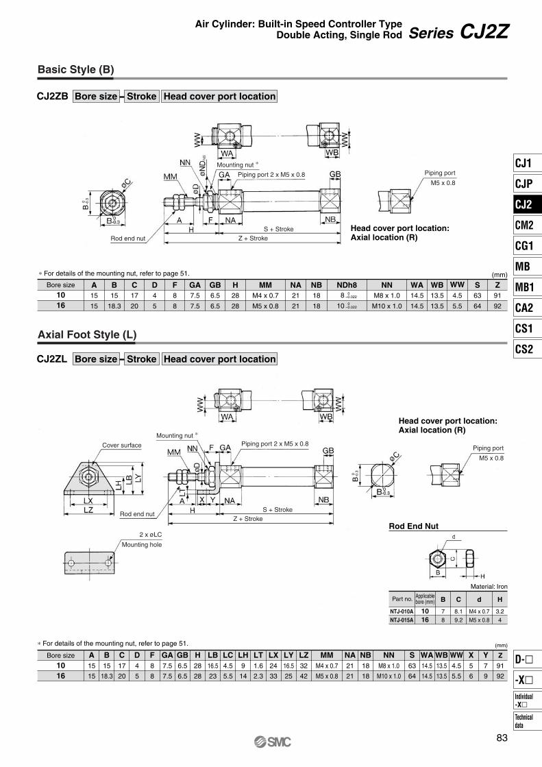
Bore size
1016
A15
15
B15
18.3
C17
20
D4
5
F8
8
GA7.5
7.5
GB6.5
6.5
H28
28
MMM4 x 0.7
M5 x 0.8
NA21
21
NB18
18
NDh8 NNM8 x 1.0
M10 x 1.0
WA14.5
14.5
WB13.5
13.5
WW4.5
5.5
S63
64
Z91
92
8
10
0–0.022
0–0.022
(mm)∗ For details of the mounting nut, refer to page 51.
NTJ-010ANTJ-015A
1016
B
7
8
C
8.1
9.2
d
M4 x 0.7
M5 x 0.8
H
3.2
4
Material: Iron
Bore size
1016
A15
15
B15
18.3
C17
20
D4
5
F8
8
GA7.5
7.5
GB6.5
6.5
H28
28
LB16.5
23
LC4.5
5.5
LH9
14
LT1.6
2.3
LX24
33
LY16.5
25
LZ32
42
MMM4 x 0.7
M5 x 0.8
NA21
21
NB18
18
NNM8 x 1.0
M10 x 1.0
S63
64
WA14.5
14.5
WB13.5
13.5
WW4.5
5.5
X5
6
Y7
9
Z
91
92
(mm)
B0 -0.3
B0 -0.3
83
Series CJ2ZAir Cylinder: Built-in Speed Controller TypeDouble Acting, Single Rod
Basic Style (B)
CJ2ZB Head cover port locationBore size Stroke
Head cover port location:Axial location (R)
Axial Foot Style (L)
CJ2ZL Head cover port locationBore size Stroke
Head cover port location:Axial location (R)
Rod End Nut
Part no. Applicablebore (mm)
∗ For details of the mounting nut, refer to page 51.
Mounting nut ∗
Rod end nut
S + StrokeZ + Stroke
Piping port 2 x M5 x 0.8 Piping port
M5 x 0.8
Mounting nut ∗
Rod end nutS + Stroke
Z + Stroke
Piping port 2 x M5 x 0.8Piping port
M5 x 0.8
2 x øLC
Mounting hole
Cover surface
CJ1
CJP
CJ2
CM2
CG1
MB
MB1
CA2
CS1
CS2
Individual-X�
D-�
-X�
Technicaldata
P0015-P0124-E.qxd 08.10.2 4:01 PM Page 83

Bore size
1016
A15
15
B15
18.3
C17
20
D4
5
F8
8
FB14.5
19
FC4.5
5.5
FT1.6
2.3
FX24
33
FY14
20
FZ32
42
GA7.5
7.5
GB6.5
6.5
H28
28
MMM4 x 0.7
M5 x 0.8
NA21
21
NB18
18
NNM8 x 1.0
M10 x 1.0
WA14.5
14.5
WB13.5
13.5
WW4.5
5.5
S63
64
Z91
92
(mm)
NTJ-010ANTJ-015A
1016
B
7
8
C
8.1
9.2
d
M4 x 0.7
M5 x 0.8
H
3.2
4
Material: Iron
Bore size
1016
A15
15
Bore size
1016
TC4.5
5.5
TH29
35
TV40
48
TW22
28
TX32
38
TY12
16
B15
18.3
C17
20
3.3
5
CX3.2
6.5
CZ15
18.3
D4
5
GA7.5
7.5
GB19.5
24.5
H28
28
MMM4 x 0.7
M5 x 0.8
NA21
21
NB31
36
R5
8
S63
64
U8
10
WA14.5
14.5
WB26.5
31.5
WW4.5
5.5
Z99
102
ZZ110
116
CD(cd)
(mm)
(mm)
B0 -0.3
CZ
0 -0.3
B0 -0.3
84
Series CJ2Z
Rod Side Flange Style (F)
CJ2ZF Head cover port locationBore size Stroke
Head cover port location:Axial location (R)
∗ For details of the mounting nut, refer to page 51.
Double Clevis Style (D)
CJ2ZD Bore size Stroke
Rod End Nut
Part no. Applicablebore (mm)
T-bracket Dimensions
∗ Clevis pin and retaining ring are shipped together.
Mounting nut ∗
S + Stroke
Z + Stroke
Piping port 2 x M5 x 0.8 Piping port
M5 x 0.8
Cover surface
Rod end nut
2 x øFCMounting hole
4 x øTC
Z + Stroke S + Stroke
Piping port 2 x M5 x 0.8Rod end nut
T-bracket
For details, refer to page 51.
øCDH9
Clevis pin(øcdd9 )
+0.030 0
–0.030 –0.060
ZZ + Stroke
P0015-P0124-E.qxd 08.10.2 4:02 PM Page 84

CDJ2ZW L
CJ2ZW L
With auto switch
With auto switch(Built-in magnet)
Bore size1016
10 mm
16 mm
Cylinder standard stroke (mm)Refer to the standard stroke table on page 86.
Applicable Auto Switch/Refer to pages 1263 to 1371 for further information on auto switches.
Mounting styleBLF
Basic style
Foot style
Flange style
4516
16 45 M9BWMade to OrderRefer to page 86 for details.
AC
A96
——
A93A90
C73CC80C
—
M9N—
M9P—
M9B—
H7CM9NW
—
M9PW—
M9BW—
H7BAH7NF
—
A72A73—
A80A73CA80C
A79W ∗∗
—
F7NV—
F7PV—
F7BVJ79C
—
F7NWV———
F7BWVF7BAV
—
A76H
A72HA73H
—
A80H———
—
F79—
F7P—
J79——
F79W—
F7PW—
J79WF7BAF79F
CDJ2ZWB16-60-A
CDJ2ZWB10-45-BExample
Rail mounting style
Band mounting style
∗ For rail mounting style, screws and nuts for 2 pcs switches come with the rail.
∗ Refer to page 123 for switch mounting brackets.
Nil
Sn
2 pcs.
1 pc.
“n” pcs.
Number of auto switchesAuto switch
∗ For the applicable auto switch model, refer to the table below.
∗ If a built-in magnet cylinder without an auto switch is required, refer to the model of built-in magnet cylinder.
—
200 V
100 V
100 V or less—
24 V or less—
Load voltage
DC
24 V
24 V
5 V
—
12 V
—
5 V, 12 V
12 V
5 V, 12 V
12 V
5 V, 12 V
—
—
Yes
Yes
YesNo
NoYes
Grommet
Grommet
Grommet
Connector
Connector
Grommet
3-wire(NPN equivalent)
2-wire
3-wire (NPN)
4-wire (NPN)
3-wire (NPN)
3-wire (PNP)
3-wire (PNP)
2-wire
2-wire
Relay,PLC
Relay,PLC
IC circuit
IC circuit
IC circuit
IC circuit
IC circuit
IC circuit
(Example) M9NW(Example) M9NWM(Example) M9NWL(Example) M9NWZ(Example) H7CN
∗ Since there are other applicable auto switches than listed, refer to page 123 for details. ∗ For details about auto switches with pre-wired connector, refer to pages 1328 and 1329. ∗ Band mounting style is not available for D-A9�V/M9�V/M9�WV and D-M9�A(V)L types. ∗∗ “D-A79W” cannot be mounted on bore size ø10 cylinder with air cushion.
∗ Solid state auto switches marked with “�” are produced upon receipt of order.∗ D-A9�/M9�/M9�W/A7��/A80�/F7��/J7�� auto switches are shipped together (not assembled). (However, when D-A9�/M9�/M9�W types are selected,
only auto switch mounting brackets are assembled before being shipped.)∗ When D-A9�(V)/M9�(V)/M9�W(V) types are mounted on a ø10 or ø16 rail, order auto switch mounting brackets separately. Refer to page 123 for details.
85
Air Cylinder: Built-in Speed Controller TypeDouble Acting, Double Rod
Series CJ2ZWø10, ø16
How to Order
Built-in Magnet Cylinder ModelSuffix the symbol “-A” (Rail mounting style) or “-B” (Band mounting style) to the end of part number for cylinder with auto switch.
Type Special function Electricalentry
Indica
tor lig
ht
Ree
d s
wit
chS
olid
sta
te s
wit
ch
Diagnostic indication(2-color indication)
Water resistant (2-color indication)With diagnostic output (2-color indication)
Diagnostic indication (2-color indication)
Wiring(Output)
Lead wire length (m)0.5(Nil)
3(L)
1(M)
5(Z)
None(N)
Applicable loadAuto switch model
Bandmounting
Rail mountingPerpendicular In-line
Pre-wired connector
∗ Lead wire length symbols: 0.5 m········· 1 m········· 3 m········· 5 m········· None·········
NilMLZN
CJ1
CJP
CJ2
CM2
CG1
MB
MB1
CA2
CS1
CS2
Individual-X�
D-�
-X�
Technicaldata
P0015-P0124-E.qxd 08.10.2 4:02 PM Page 85

1610Bore size (mm)
Action
Fluid
Proof pressure
Maximum operating pressure
Minimum operating pressure
Ambient and fluid temperature
Cushion
Lubrication
Stroke length tolerance
Speed controller
Piston speed
Allowable kinetic energy
50 to 750 mm/s
0.035 J 0.090 J
Specifications
Double acting, Single rod
Air
1 MPa
0.7 MPa
0.1 MPa
Without auto switch: –10°C to 70°C, With auto switch: –10°C to 60°C
Rubber bumper
Not required (Non-lube)
Built-in
+1.00
∗ No freezing
∗ Knuckle pin and retaining ring are shipped together with double knuckle joint.
Mounting Style and Accessory/For details, refer to page 51.
Mounting Bracket Part No.
Mounting bracket
Foot bracket
Flange bracket
10CJ-L010B
CJ-F010B
Bore size (mm)
16CJ-L016B
CJ-F016B
—XA�—XC51
Change of rod end shape
With hose nipple
Symbol Specifications
JIS SymbolDouble acting, Double rod
Bore size
10
16
Standard stroke
15, 30, 45, 60
15, 30, 45, 60
Standard Stroke (mm)
∗ Manufacture of intermediate strokes at 1 mm intervals is possible. (Spacers are not used.)
• Minimum stroke for auto switch mounting• Proper auto switch mounting position (detection at stroke end) and mounting height• Operating range• Switch mounting bracket part no.
Refer to pages 117 to 123 for cylinders with auto switches.
Refer to page 44 before handling.
Precautions
86
Made to Order Specifications(For details, refer to pages 1380 and 1479.)
Series CJ2ZW
Space-saving air cylinder with speed controller built-in cylinder cover
Mounting
Standardequipment
Option
Mounting nut
Rod end nut
Single knuckle joint
Double knuckle joint ∗
Basic style Foot style Flange style
P0015-P0124-E.qxd 08.10.2 4:02 PM Page 86

10
50
6
16
5
16
85
9
40
15
Mass
SpecificationsAction
Bore size (mm)
Maximum operating pressure
Minimum operating pressure
Cushion
Standard stroke (mm)
Auto switch
Mounting
Double acting, Double rod
10, 16
0.7 MPa
0.1 MPa
Rubber bumper
15, 30, 45, 60
Mountable (Band mounting style)
Basic style, Foot style, Flange style
(g)
Component PartsNo.
12345678
Description Material
Aluminum alloy
Stainless steel
Stainless steel
Brass
Urethane
Stainless steel
Bearing steel
Brass
Note
Anodized
Nickel plated
Rod coverCylinder tubePiston rodPiston BumperSpeed controller needleSteel ballsMounting nut
No.
9101112131415
Description Material
Rolled steel
NBR
NBR
NBR
NBR
NBR
NBR
Note
Nickel platedRod end nutPiston sealRod sealCheck sealTube gasketPiston gasketNeedle seal
Copper and Fluorine-free Air Cylinder (For CRT manufacturing process)
Eliminates the effects by copper based ions and fluorine based resins, etc. over the color cathode ray tube.Making copper based materials into electroless nickel plated treatment or changing them to the non-copper materials in order to prevent copper ions from generating.
87
Series CJ2ZWAir Cylinder: Built-in Speed Controller TypeDouble Acting, Double Rod
20-CJ2ZW
Copper and fluorine-free
Bore size (mm)
Basic mass ∗
Additional mass per each 15 mm of stroke
Foot style
Flange style
Mountingbracket mass
∗ Rod end nut are included in the basic mass.Calculation: (Example)
CJ2ZWL10-45 • Basic mass ······························· 50 (ø10)• Additional mass ························ 6/15 stroke• Cylinder stroke ·························· 45 stroke• Mounting bracket mass ············· 16 (Axial foot style)
50 + 6/15 x 45 + 16 = 84 g
Bore sizeMounting style Stroke Head coverport location
Construction (Not able to disassemble)
CJ1
CJP
CJ2
CM2
CG1
MB
MB1
CA2
CS1
CS2
Individual-X�
D-�
-X�
Technicaldata
P0015-P0124-E.qxd 08.10.2 4:02 PM Page 87

B 0 –0
.3
B 0 –0
.3
Bore size
1016
A15
15
B15
18.3
C17
20
D4
5
F8
8
GA7.5
7.5
H28
28
MMM4 x 0.7
M5 x 0.8
NA21
21
NNM8 x 1.0
M10 x 1.0
WA14.5
14.5
WW4.5
5.5
S66
67
Z122
123
(mm)∗ For details of the mounting nut, refer to page 51.
NDh88
10
0–0.022
0–0.022
NTJ-010ANTJ-015A
1016
B
7
8
C
8.1
9.2
d
M4 x 0.7
M5 x 0.8
H
3.2
4
Material: Iron
Bore size
1016
A15
15
B15
18.3
D4
5
F8
8
H28
28
LB16.5
23
LC4.5
5.5
LH9
14
LT1.6
2.3
LX24
33
LY16.5
25
LZ32
42
GA7.5
7.5
MMM4 x 0.7
M5 x 0.8
NA21
21
NNM8 x 1.0
M10 x 1.0
S66
67
WA14.5
14.5
WW4.5
5.5
X5
6
Y7
9
Z122
123
∗ For details of the mounting nut, refer to page 51. (mm)
88
Series CJ2ZW
Basic Style (B)
CJ2ZWB Bore size Stroke
Foot Style (L)
CJ2ZWL Bore size Stroke
Rod End Nut
Part no. Applicablebore (mm)
H + StrokeRod end nut S + Stroke
Piping port 2 x M5 x 0.8
Mounting nut ∗
Z + 2 x Stroke
H + Stroke
Rod end nut
Z + 2 x Stroke
S + Stroke2 x øLCMounting hole
Mounting nut ∗
Cover surface Piping port 2 x M5 x 0.8
P0015-P0124-E.qxd 08.10.2 4:02 PM Page 88

NTJ-010ANTJ-015A
1016
B
7
8
C
8.1
9.2
d
M4 x 0.7
M5 x 0.8
H
3.2
4
Material: Iron
Bore size
1016
A15
15
B15
18.3
D4
5
F8
8
H28
28
FB14.5
19
FC4.5
5.5
FT1.6
2.3
FX24
33
FY14
20
FZ32
42
GA7.5
7.5
MMM4 x 0.7
M5 x 0.8
NA21
21
NNM8 x 1.0
M10 x 1.0
S66
67
WA14.5
14.5
WW4.5
5.5
Z122
123
∗ For details of the mounting nut, refer to page 51. (mm)
89
Series CJ2ZWAir Cylinder: Built-in Speed Controller TypeDouble Acting, Double Rod
Flange Style (F)
CJ2ZWF Bore size Stroke
Rod End Nut
Part no. Applicablebore (mm)
H + Stroke
Rod end nut Z + 2 x Stroke
S + Stroke
2 x øFCMounting hole
Mounting nut ∗
Cover surface Piping port 2 x M5 x 0.8
CJ1
CJP
CJ2
CM2
CG1
MB
MB1
CA2
CS1
CS2
Individual-X�
D-�
-X�
Technicaldata
P0015-P0124-E.qxd 08.10.2 4:02 PM Page 89
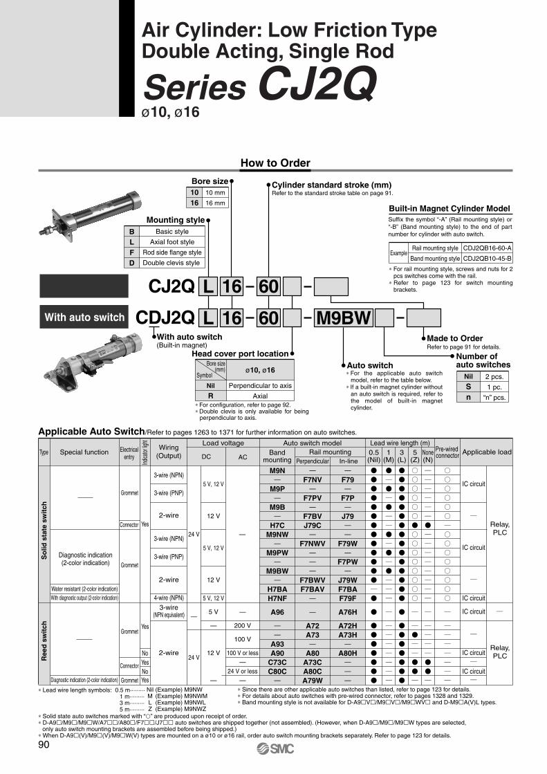
CDJ2Q
CJ2Q
M9BWWith auto switch
With auto switch(Built-in magnet)
Mounting styleBLFD
Basic style
Axial foot style
Rod side flange style
Double clevis style
Bore size1016
10 mm
16 mm
Cylinder standard stroke (mm)Refer to the standard stroke table on page 91.
Head cover port location
Applicable Auto Switch/Refer to pages 1263 to 1371 for further information on auto switches.
Nil
RPerpendicular to axis
Axial
ø10, ø16
L
L
16
16
60
60Made to OrderRefer to page 91 for details.
A96
——
A93A90
C73CC80C
—
M9N—
M9P—
M9B—
H7CM9NW
—
M9PW—
M9BW—
H7BAH7NF
—
A72A73—
A80A73CA80CA79W
—
F7NV—
F7PV—
F7BVJ79C
—
F7NWV———
F7BWVF7BAV
—
A76H
A72HA73H
—
A80H———
—
F79—
F7P—
J79——
F79W—
F7PW—
J79WF7BAF79F
CDJ2QB16-60-A
CDJ2QB10-45-BExample
Rail mounting style
Band mounting style
∗ For rail mounting style, screws and nuts for 2 pcs switches come with the rail.
∗ Refer to page 123 for switch mounting brackets.
Auto switch∗ For the applicable auto switch
model, refer to the table below.∗ If a built-in magnet cylinder without
an auto switch is required, refer to the model of built-in magnet cylinder.
Nil
Sn
2 pcs.
1 pc.
“n” pcs.
Number of auto switches
AC
—
200 V
100 V
100 V or less—
24 V or less—
Load voltage
DC
24 V
24 V
5 V
—
12 V
—
5 V, 12 V
12 V
5 V, 12 V
12 V
5 V, 12 V
—
—
Yes
Yes
YesNo
NoYes
Grommet
Grommet
Grommet
Connector
Connector
Grommet
3-wire(NPN equivalent)
2-wire
3-wire (NPN)
4-wire (NPN)
3-wire (NPN)
3-wire (PNP)
3-wire (PNP)
2-wire
2-wire
Relay,PLC
Relay,PLC
IC circuit
IC circuit
IC circuit
IC circuit
IC circuit
IC circuit
(Example) M9NW(Example) M9NWM(Example) M9NWL(Example) M9NWZ
∗ Since there are other applicable auto switches than listed, refer to page 123 for details.∗ For details about auto switches with pre-wired connector, refer to pages 1328 and 1329.∗ Band mounting style is not available for D-A9�V�/M9�V�/M9�WV� and D-M9�A(V)L types.
∗ Solid state auto switches marked with “�” are produced upon receipt of order.∗ D-A9�/M9�/M9�W/A7��/A80�/F7��/J7�� auto switches are shipped together (not assembled). (However, when D-A9�/M9�/M9�W types are selected,
only auto switch mounting brackets are assembled before being shipped.)∗ When D-A9�(V)/M9�(V)/M9�W(V) types are mounted on a ø10 or ø16 rail, order auto switch mounting brackets separately. Refer to page 123 for details.
90
Air Cylinder: Low Friction TypeDouble Acting, Single Rod
Series CJ2Qø10, ø16
How to Order
Built-in Magnet Cylinder ModelSuffix the symbol “-A” (Rail mounting style) or “-B” (Band mounting style) to the end of part number for cylinder with auto switch.
Symbol
Bore size(mm)
∗ For configuration, refer to page 92.∗ Double clevis is only available for being
perpendicular to axis.
Type Special function Electricalentry
Indica
tor lig
ht
Ree
d s
wit
chS
olid
sta
te s
wit
ch
Diagnostic indication(2-color indication)
Water resistant (2-color indication)With diagnostic output (2-color indication)
Diagnostic indication (2-color indication)
Wiring(Output)
Lead wire length (m)0.5(Nil)
3(L)
1(M)
5(Z)
None(N)
Applicable loadAuto switch model
Bandmounting
Rail mountingPerpendicular In-line
Pre-wired connector
∗ Lead wire length symbols: 0.5 m········· 1 m········· 3 m········· 5 m·········
NilMLZ
P0015-P0124-E.qxd 08.10.2 4:02 PM Page 90

10 16Bore size (mm)
Low sliding resistanceMinimum operating pressure: 0.03 MPa
JIS SymbolDouble acting, Single rod
Action
Fluid
Proof pressure
Maximum operating pressure
Minimum operating pressure
Ambient and fluid temperature
Cushion
Lubrication
Stroke length tolerance
Piston speed
Allowable kinetic energy
50 to 750 mm/s
Specifications
Double acting, Single rod
Air
1 MPa
0.7 MPa
0.03 MPa
Without auto switch: –10°C to 70°C, With auto switch: –10°C to 60°C ∗
Rubber bumper
Not applicable
+1.00
∗ No freezing
Bore size Standard stroke
Standard Stroke (mm)
10
16
15, 30, 45, 60, 75,100, 125, 150
15, 30, 45, 60, 75,100, 125, 150, 175, 200
∗ Manufacture of intermediate strokes at 1 mm intervals is possible. (Spacers are not used.)
—XA�—XC51
Change of rod end shape
With hose nipple
Symbol Specifications
0.090 J0.035 J
Refer to page 44 before handling.
Precautions
• Minimum stroke for auto switch mounting• Proper auto switch mounting position (detection at stroke end) and mounting height• Operating range• Switch mounting bracket part no.
Refer to pages 117 to 123 for cylinders with an auto switch.
91
Made to Order Specifications(For details, refer to pages 1380 and 1479.)
Series CJ2QAir Cylinder: Low Friction TypeDouble Acting, Single Rod
Specially designed to keep friction of the piston to a minimum. Suitable for contact-pressure control requiring smooth operation at low pressures.
Application Example
Low friction cylinder is used in combination with precision regulator (Series IR).
Moving object
Driving roller Winding roller
Precision regulatorPrecision regulator
CJ1
CJP
CJ2
CM2
CG1
MB
MB1
CA2
CS1
CS2
Individual-X�
D-�
-X�
Technicaldata
P0015-P0124-E.qxd 08.10.2 4:02 PM Page 91

Sliding Resistance of the Low Friction Side
Axial Perpendicular
Either perpendicular to the cylinder axis or in-line with the cylinder axis is available for basic style.
Mounting Style and Accessory/For details, refer to page 51.
10CJ-L010B
CJ-F010B
CJ-T010B
16CJ-L016B
CJ-F016B
CJ-T016B
(g)
10
24
4
8
5
4
16
55
6.5
20
15
10
Operating pressure (MPa)
Slid
ing
resi
stan
ce ∗
(MP
a)
0 0.1 0.2 0.3 0.4 0.5 0.6 0.7
0.01
0.02
0.03
0.04
0.05
0.06
0.07
0.08
ø10
ø16
∗ Conversion into the cylinder operating pressure:
Head Cover Port Location
92
Series CJ2Q
∗ Pin and retaining ring are shipped together with double clevis and double knuckle joint.
Mounting
Sta
ndar
deq
uipm
ent
Opt
ion
Mounting nut
Rod end nut
Clevis pin
Single knuckle joint
Double knuckle joint ∗
T-bracket
Basicstyle
Axialfoot style
Rod sideflange style
Double ∗clevis style
Mounting Bracket Part No.Bore size (mm)
Mounting bracket
Foot bracket
Flange bracket
T-bracket ∗
∗ T-bracket is used with double clevis (D).
MassBore size (mm)
Basic mass ∗
Additional mass per each 15 mm of stroke
Mountingbracket mass
Axial foot style
Rod side flange style
Double clevis style (With pin) ∗∗
∗ Mounting nut and rod end nut are included in the basic mass.∗∗ Mounting nut is not attached to the double clevis style, so the mounting
nut mass is already subtracted.Calculation: (Example) CJ2QL10-45
• Basic mass ························· 24 (ø10)• Additional mass ·················· 4/15 stroke• Cylinder stroke···················· 45 stroke• Mounting bracket mass ······ 8 (Axial foot style)
24 + 4/15 x 45 + 8 = 44 g
P0015-P0124-E.qxd 08.10.2 4:02 PM Page 92

Component PartsNo.
123456
Description Material
Aluminum alloy
Aluminum alloy
Stainless steel
Stainless steel
Brass
Brass
Note
Anodized
Anodized
Nickel plated
Rod coverHead coverCylinder tubePiston rodPiston Mounting nut
No.
789101112
Description Material
Rolled steel
Urethane
NBR
NBR
NBR
NBR
Note
Nickel plated
For low friction
For low friction
Rod end nutBumperPiston sealRod sealTube gasketPiston gasket
Bore size
1016
A15
15
B12
18.3
C14
20
D4
5
F8
8
GA8
8
GB5
5
H28
28
MMM4 x 0.7
M5 x 0.8
NA12.5
12.5
NB9.5
9.5
ND NNM8 x 1.0
M10 x 1.0
S46
47
Z74
758
10
0–0.022
0–0.022
(mm)∗ For details of the mounting nut, refer to page 51.
NTJ-010ANTJ-015A
1016
B
7
8
C
8.1
9.2
d
M4 x 0.7
M5 x 0.8
H
3.2
4
Material: Iron
For dimensions of each mounting bracket, refer to pages 48 to 50.
93
Series CJ2QAir Cylinder: Low Friction TypeDouble Acting, Single Rod
Construction (Not able to disassemble)
Basic Style (B)
CJ2QB Head cover port locationBore size Stroke
Rod End Nut
Head cover port location:Axial location (R)
Part no. Applicablebore (mm)
Rod end nutMounting nut ∗
Piping port 2 x M5 x 0.8
S + Stroke
Piping port
M5 x 0.8
Z + Stroke
CJ1
CJP
CJ2
CM2
CG1
MB
MB1
CA2
CS1
CS2
Individual-X�
D-�
-X�
Technicaldata
P0015-P0124-E.qxd 08.10.2 4:02 PM Page 93

CDJ2RA
CJ2RA
M9BWWith auto switch
Mounting style
Bore size1016
10 mm
16 mm
Cylinder standard stroke (mm)Refer to the standard stroke table on page 95.
With auto switch(Built-in magnet)
Applicable Auto Switch/Refer to pages 1263 to 1371 for further information on auto switches.
A Bottom mounting style
16
16
60
60Made to OrderRefer to page 95 for details.
A96
——
A93A90
C73CC80C
—
M9N—
M9P—
M9B—
H7CM9NW
—M9PW
—M9BW
—H7BAH7NF
—
A72A73—
A80A73CA80CA79W
—F7NV
—F7PV
—F7BVJ79C
—F7NWV
———
F7BWVF7BAV
—
A76H
A72HA73H
—A80H
———
—F79—
F7P—
J79——
F79W—
F7PW—
J79WF7BAF79F
CDJ2RA16-60-A
CDJ2RA10-45-BExample
Rail mounting style
Band mounting style
∗ For rail mounting style, screws and nuts for 2 pcs switches come with the rail.
∗ Refer to page 123 for switch mounting brackets.
Nil
Sn
2 pcs.
1 pc.
“n” pcs.
Number of auto switchesAuto switch
∗ For the applicable auto switch model, refer to the table below.
∗ If a built-in magnet cylinder without an auto switch is required, refer to the model of built-in magnet cylinder.
Head cover port location
Nil
RPerpendicular to axis
Axial
ø10, ø16
AC
—
200 V
100 V
100 V or less—
24 V or less—
Load voltage
DC
24 V
24 V
5 V
—
12 V
—
5 V, 12 V
12 V
5 V, 12 V
12 V
5 V, 12 V
—
—
Yes
Yes
YesNo
NoYes
Grommet
Grommet
Grommet
Connector
Connector
Grommet
3-wire(NPN equivalent)
2-wire
3-wire (NPN)
4-wire (NPN)
3-wire (NPN)
3-wire (PNP)
3-wire (PNP)
2-wire
2-wire
Relay,PLC
Relay,PLC
IC circuit
IC circuit
IC circuit
IC circuit
IC circuit
IC circuit
(Example) M9NW(Example) M9NWM(Example) M9NWL(Example) M9NWZ
∗ Since there are other applicable auto switches than listed, refer to page 123 for details.∗ For details about auto switches with pre-wired connector, refer to pages 1328 and 1329.∗ Band mounting style is not available for D-A9�V�/M9�V�/M9�WV� and D-M9�A(V)L types.
∗ Solid state auto switches marked with “�” are produced upon receipt of order.∗ D-A9�/M9�/M9�W/A7��/A80�/F7��/J7�� auto switches are shipped together (not assembled). (However, when D-A9�/M9�/M9�W types are selected,
only auto switch mounting brackets are assembled before being shipped.)∗ When D-A9�(V)/M9�(V)/M9�W(V) types are mounted on a ø10 or ø16 rail, order auto switch mounting brackets separately. Refer to page 123 for details.
94
Air Cylinder: Direct Mount TypeDouble Acting, Single Rod
Series CJ2Rø10, ø16
How to Order
Built-in Magnet Cylinder ModelSuffix the symbol “-A” (Rail mounting style) or “-B” (Band mounting style) to the end of part number for cylinder with auto switch.
Symbol
Bore size(mm)
∗ For configuration, refer to page 95.
Type Special function Electricalentry
Indica
tor lig
ht
Ree
d s
wit
chS
olid
sta
te s
wit
ch
Diagnostic indication(2-color indication)
Water resistant (2-color indication)With diagnostic output (2-color indication)
Diagnostic indication (2-color indication)
Wiring(Output)
Lead wire length (m)0.5(Nil)
3(L)
1(M)
5(Z)
None(N)
Applicable loadAuto switch model
Bandmounting
Rail mountingPerpendicular In-line
Pre-wired connector
∗ Lead wire length symbols: 0.5 m········· 1 m········· 3 m········· 5 m·········
NilMLZ
P0015-P0124-E.qxd 08.10.2 4:02 PM Page 94

10 16Bore size (mm)
JIS SymbolDouble acting, Single rod
Action
Fluid
Proof pressure
Maximum operating pressure
Minimum operating pressure
Ambient and fluid temperature
Cushion
Lubrication
Stroke length tolerance
Piston speed
Allowable kinetic energy
50 to 750 mm/s
0.035 J 0.090 J
Specifications
Double acting, Single rod
Air
1 MPa
0.7 MPa
0.06 MPa
Without auto switch: –10°C to 70°C, With auto switch: –10°C to 60°C ∗
Rubber bumper
Not required (Non-lube) +1.0
0
∗ No freezing
Bore size
10
16
Standard stroke
15, 30, 45, 60, 75, 100, 125, 150
15, 30, 45, 60, 75, 100, 125, 150, 175, 200
Standard Stroke (mm)
∗ Manufacture of intermediate strokes at 1 mm intervals is possible. (Spacers are not used.)
—XA�—XC22
—XC51
Change of rod end shape
Fluororubber seals
With hose nipple
Symbol Specifications
Mass (g)
Bore size (mm) 10
36
4
16
71.5
6.5
Basic mass ∗
Additional mass per each 15 mm of stroke
Refer to page 44 before handling.
Precautions • Minimum stroke for auto switch mounting• Proper auto switch mounting position (detection at stroke end) and mounting height• Operating range• Switch mounting bracket part no.
Refer to pages 117 to 123 for cylinders with auto switches.
Head Cover Port Location
Either perpendicular to the cylinder axis or in-line with the cylinder axis is available for basic style.
Axial Perpendicular
95
Made to Order Specifications(For details, refer to pages 1380, 1462 and 1479.)
Series CJ2RAir Cylinder: Direct Mount TypeDouble Acting, Single Rod
Series CJ2R direct mount cylinder can be installed directly through the use of a square rod cover.
∗ Rod end nut is included in the basic mass.Calculation: (Example) CJ2RA10-45
• Basic mass ·························· 36 (ø10)• Additional mass ··················· 4/15 stroke• Cylinder stroke ····················· 45 stroke
36 + 4/15 x 45 = 48 g
CJ1
CJP
CJ2
CM2
CG1
MB
MB1
CA2
CS1
CS2
Individual-X�
D-�
-X�
Technicaldata
P0015-P0124-E.qxd 08.10.2 4:02 PM Page 95

SpecificationsAction
Bore size (mm)
Maximum operating pressure
Minimum operating pressure
Cushion
Standard stroke (mm)
Auto switch
Mounting
Double acting, Single rod
10, 16
0.7 MPa
0.08 MPa
Rubber bumper
Same as the standard. (Refer to page 95.)
Mountable (Band mounting style)
Bottom mounting style
For details, specifications about the Clean Series, refer to the separate catalog “Pneumatic Clean Series”.
Specifications
Action
Maximum operating pressure
Minimum operating pressure
Cushion
Standard stroke (mm)
Auto switch
Mounting
Double acting, Single rod
0.7 MPa
0.06 MPa
Rubber bumper (Standard equipment)
Same as standard type. (Refer to page 95.)
Mountable (Band mounting style)
Bottom mounting style
10, 16Bore size (mm)
10-CJ2RA (Clean series) Construction (Not able to disassemble)
96
Series CJ2R
Air cylinder which is applicable for the system which discharges leakage from the rod section directly into the outside of clean room by relief port and making an actuator’s rod section having a double seal construction.
Eliminates the effects by copper based ions and fluorine based resins, etc. over the color cathode ray tube.Making copper based materials into electroless nickel plated treatment or changing them to the non-copper materials in order to prevent copper ions from generating.
Clean Series
10-CJ2RA 20-CJ2RA
Clean Series Copper and fluorine-free
Copper and Fluorine-free Air Cylinder(For CRT manufacturing process)
Bore size Stroke Head cover port location Bore size Stroke Head cover port location
P0015-P0124-E.qxd 08.10.2 4:02 PM Page 96

Component PartsNo.
123456
Description Material
Aluminum alloy
Aluminum alloy
Stainless steel
Stainless steel
Brass
Rolled steel
Note
Anodized
Anodized
Nickel plated
Rod coverHead coverCylinder tubePiston rodPiston Rod end nut
No.
7891011
Description Material
Urethane
NBR
NBR
NBR
NBR
Note
BumperPiston sealRod sealPiston gasketTube gasket
Bore size
1016
A15
15
B12
18.3
C14
20
D4
5
L23
26
LB16
20
GA16
16
GB5
5
H20
20
MMM4 x 0.7
M5 x 0.8
LDø3.5, ø6.5 counterbore depth 4
ø4.5, ø8 counterbore depth 5
NA20.5
20.5
NB9.5
9.5
LH 8
10
LX12
16
X28
28
Y8
8
S54
55
Z74
75
(mm)
NTJ-010ANTJ-015A
1016
B
7
8
C
8.1
9.2
d
M4 x 0.7
M5 x 0.8
H
3.2
4
Material: Iron
97
Series CJ2RAir Cylinder: Direct Mount TypeDouble Acting, Single Rod
Construction (Not able to disassemble)
Bottom Mounting Style
CJ2RA Head cover port locationBore size Stroke
Rod End Nut
Head cover port location:Axial location (R)
Part no. Applicablebore (mm)
Rod end nut
Piping port 2 x M5 x 0.8
S + Stroke
Piping port M5 x 0.8
Z + Stroke
CJ1
CJP
CJ2
CM2
CG1
MB
MB1
CA2
CS1
CS2
Individual-X�
D-�
-X�
Technicaldata
P0015-P0124-E.qxd 08.10.2 4:02 PM Page 97

45
CDJ2RA
CJ2RA
With auto switch
With auto switch(Built-in magnet)
Bore size1016
10 mm
16 mm
Cylinder standard stroke (mm)Refer to the standard stroke table on page 99.
Action
Applicable Auto Switch/Refer to pages 1263 to 1371 for further information on auto switches.
ST
Single acting, Spring return
Single acting, Spring extend
16 45
4516
M9BWMade to OrderRefer to page 99 for details.
S
S
A96
——
A93A90
C73CC80C
—
M9N—
M9P—
M9B—
H7CM9NW
—M9PW
—M9BW
—H7BAH7NF
—
A72A73—
A80A73CA80CA79W
—F7NV
—F7PV
—F7BVJ79C
—F7NWV
———
F7BWVF7BAV
—
A76H
A72HA73H
—A80H
———
—F79—
F7P—
J79——
F79W—
F7PW—
J79WF7BAF79F
Mounting styleA Bottom mounting style CDJ2RA16-60S-A
CDJ2RA10-45S-BExample
Rail mounting style
Band mounting style
∗ For rail mounting style, screws and nuts for 2 pcs switches come with the rail.
∗ Refer to page 123 for switch mounting brackets.
Head cover port location
Nil
RPerpendicular to axis
Axial
ø10, ø16Auto switch∗ For the applicable auto switch
model, refer to the table below.∗ If a built-in magnet cylinder without
an auto switch is required, refer to the model of built-in magnet cylinder.
Nil
Sn
2 pcs.
1 pc.
“n” pcs.
Number of auto switches
AC
—
200 V
100 V
100 V or less—
24 V or less—
Load voltage
DC
24 V
24 V
5 V
—
12 V
—
5 V, 12 V
12 V
5 V, 12 V
12 V
5 V, 12 V
—
—
Yes
Yes
YesNo
NoYes
Grommet
Grommet
Grommet
Connector
Connector
Grommet
3-wire(NPN equivalent)
2-wire
3-wire (NPN)
4-wire (NPN)
3-wire (NPN)
3-wire (PNP)
3-wire (PNP)
2-wire
2-wire
Relay,PLC
Relay,PLC
IC circuit
IC circuit
IC circuit
IC circuit
IC circuit
IC circuit
(Example) M9NW(Example) M9NWM(Example) M9NWL(Example) M9NWZ(Example) H7CN
∗ Since there are other applicable auto switches than listed, refer to page 123 for details.∗ For details about auto switches with pre-wired connector, refer to pages 1328 and 1329.∗ Band mounting style is not available for D-A9�V�/M9�V�/M9�WV� and D-M9�A(V)L types.
∗ Solid state auto switches marked with “�” are produced upon receipt of order.∗ D-A9�/M9�/M9�W/A7��/A80�/F7��/J7�� auto switches are shipped together (not assembled). (However, when D-A9�/M9�/M9�W types are selected,
only auto switch mounting brackets are assembled before being shipped.)∗ When D-A9�(V)/M9�(V)/M9�W(V) types are mounted on a ø10 or ø16 rail, order auto switch mounting brackets separately. Refer to page 123 for details.
98
Air Cylinder: Direct Mount TypeSingle Acting, Spring Return/Extend
Series CJ2Rø10, ø16
How to Order
Built-in Magnet Cylinder ModelSuffix the symbol “-A” (Rail mounting style) or “-B” (Band mounting style) to the end of part number for cylinder with auto switch.
Symbol
Bore size(mm)
∗ For configuration, refer to page 99.∗ Not applicable to single acting,
spring extend (T).
Type Special function Electricalentry
Indica
tor lig
ht
Ree
d s
wit
chS
olid
sta
te s
wit
ch
Diagnostic indication(2-color indication)
Water resistant (2-color indication)With diagnostic output (2-color indication)
Diagnostic indication (2-color indication)
Wiring(Output)
Lead wire length (m)0.5(Nil)
3(L)
1(M)
5(Z)
None(N)
Applicable loadAuto switch model
Bandmounting
Rail mountingPerpendicular In-line
Pre-wired connector
∗ Lead wire length symbols: 0.5 m········· 1 m········· 3 m········· 5 m········· None·······
NilMLZN
P0015-P0124-E.qxd 08.10.2 4:02 PM Page 98

10 16Bore size (mm)
Action
Fluid
Proof pressure
Maximum operating pressure
Minimum operating pressure
Ambient and fluid temperature
Cushion
Lubrication
Stroke length tolerance
Piston speed
Allowable kinetic energy
50 to 750 mm/s
Specifications
+1.00
∗ No freezing
Bore size
10
16
15, 30, 45, 60
15, 30, 45, 60, 75, 100, 125, 150
Standard Stroke (mm)
Accessory/For details, refer to page 51.
Standard equipment
Option
Rod end nut
Single knuckle joint, Double knuckle joint ∗
∗ Knuckle pin and retaining ring are shipped together with double knuckle joint.
Single acting, Spring return/Single acting, Spring extend
Air
1 MPa
0.7 MPa
0.15 MPa
Without auto switch: –10°C to 70°C, With auto switch: –10°C to 60°C ∗
Rubber bumper
Not required (Non-lube)
∗ Manufacture of intermediate strokes at 1 mm intervals is possible. (Spacers are not used.)
—XA�—XC51
Change of rod end shape
With hose nipple
Symbol Specifications
(N)Spring Force
1016
6.86
14.2
3.53
6.86
Standard stroke
0.035 J 0.090 J
Refer to page 44 before handling.
Precautions
Head Cover Port Location
Either perpendicular to the cylinder axis or in-line with the cylinder axis is available for basic style.
Axial Perpendicular
• Minimum stroke for auto switch mounting• Proper auto switch mounting position (detection at stroke end) and mounting height• Operating range• Switch mounting bracket part no.
Refer to pages 117 to 123 for cylinders with auto switches.
99
Made to Order Specifications(For details, refer to pages 1380 and 1479.)
Series CJ2RAir Cylinder: Direct Mount TypeSingle Acting, Spring Return/Extend
Series CJ2R direct mount cylinder can be installed directly through the use of a square rod cover.
JIS SymbolSingle acting, Spring return
Single acting, Spring extend
Bore size(mm)
Retracted side Extended side
CJ1
CJP
CJ2
CM2
CG1
MB
MB1
CA2
CS1
CS2
Individual-X�
D-�
-X�
Technicaldata
P0015-P0124-E.qxd 08.10.2 4:02 PM Page 99

Spring ReturnBore size (mm)
Bore size (mm)
Mass ∗
15 stroke
30 stroke
45 stroke
60 stroke
75 stroke
100 stroke
125 stroke
150 stroke
10
38
45
54
63
—
—
—
—
16
73
90
112
134
155
198
234
260
Mass ∗
15 stroke
30 stroke
45 stroke
60 stroke
75 stroke
100 stroke
125 stroke
150 stroke
10
44
50
59
67
—
—
—
—
16
78
94
114
135
154
192
226
250
(g)
Spring Extend (g)
∗ Rod end nut is included in the mass.
∗ Rod end nut is included in the mass.
Specifications
Single acting, Spring return; Single acting, Spring extend
0.7 MPa
0.15 MPa
Rubber bumper (Standard equipment)
Same as standard type. (Refer to page 99.)
Mountable (Band mounting style)
Bottom mounting style
10, 16
Mass
Component PartsNo.
1234567
Description Material
Aluminum alloy
Aluminum alloy
Stainless steel
Stainless steel
Brass
Brass
Piano wire
Note
Anodized
Anodized
Zinc chromated
Rod coverHead coverCylinder tubePiston rodPiston APiston BReturn spring
No.
891011121314
Description Material
Brass
Urethane
Rolled steel
NBR
NBR
NBR
NBR
Note
Nickel plated
Spring seatBumperRod end nutPiston sealTube gasketPiston gasketRod seal
100
Series CJ2RCopper and Fluorine-free Air Cylinder(For CRT manufacturing process)
Eliminates the effects by copper based ions and fluorine based resins, etc. over the color cathode ray tube.Making copper based materials into electroless nickel plated treatment or changing them to the non-copper materials in order to prevent copper ions from generating.
20-CJ2RA
Copper and fluorine-free
Action Head coverport locationBore size Stroke
Action
Max. operating pressure
Min. operating pressure
Cushion
Standard stroke (mm)
Auto switch
Mounting
Bore size (mm)
Construction (Not able to disassemble)
P0015-P0124-E.qxd 08.10.2 4:02 PM Page 100
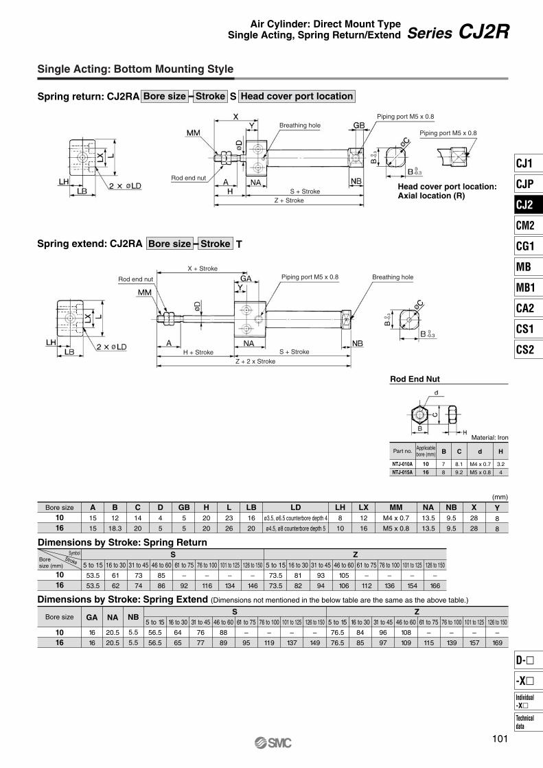
NTJ-010A
NTJ-015A
10
16
B
7
8
C
8.1
9.2
d
M4 x 0.7
M5 x 0.8
H
(mm)
Y8
8
Bore size
1016
A15
15
B12
18.3
C14
20
D4
5
GB5
5
H20
20
L23
26
LB16
20
LDø3.5, ø6.5 counterbore depth 4
ø4.5, ø8 counterbore depth 5
LH8
10
LX12
16
MMM4 x 0.7
M5 x 0.8
NA13.5
13.5
NB9.5
9.5
X28
28
Dimensions by Stroke: Spring Return
1016
S5 to 15
53.5
53.5
16 to 30
61
62
31 to 45
73
74
46 to 60
85
86
61 to 75
–
92
76 to 100
–
116
101 to 125
–
134
126 to 150
–
146
5 to 15
73.5
73.5
16 to 30
81
82
31 to 45
93
94
46 to 60
105
106
61 to 75
–
112
76 to 100
–
136
101 to 125
–
154
126 to 150
–
166
Z
Dimensions by Stroke: Spring Extend (Dimensions not mentioned in the below table are the same as the above table.)
Bore size
1016
GA
16
16
NA
20.5
20.5
NB
5.5
5.5
S5 to 15
56.5
56.5
16 to 30
64
65
31 to 45
76
77
46 to 60
88
89
61 to 75
–
95
76 to 100
–
119
101 to 125
–
137
126 to 150
–
149
5 to 15
76.5
76.5
16 to 30
84
85
31 to 45
96
97
46 to 60
108
109
61 to 75
–
115
76 to 100
–
139
101 to 125
–
157
126 to 150
–
169
Z
3.2
4
B0 –0.3
B0 –0.3
101
Series CJ2RAir Cylinder: Direct Mount TypeSingle Acting, Spring Return/Extend
Single Acting: Bottom Mounting Style
Spring return: CJ2RA S Head cover port locationBore size Stroke
Head cover port location:Axial location (R)
Spring extend: CJ2RA TBore size Stroke
Material: Iron
Rod End Nut
Part no.Applicablebore (mm)
Boresize (mm)
SymbolStroke
Z + 2 x Stroke
Rod end nut
Rod end nut
Breathing hole
Breathing hole
S + Stroke
S + Stroke
Piping port M5 x 0.8
Piping port M5 x 0.8
Piping port M5 x 0.8
X + Stroke
H + Stroke
Z + Stroke
CJ1
CJP
CJ2
CM2
CG1
MB
MB1
CA2
CS1
CS2
Individual-X�
D-�
-X�
Technicaldata
P0015-P0124-E.qxd 08.10.2 4:02 PM Page 101

CDJ2RKA
CJ2RKA
With auto switch
With auto switch(Built-in magnet)
Bore size1016
10 mm
16 mm
Cylinder standard stroke (mm)Refer to the standard stroke table on page 103.
Applicable Auto Switch/Refer to pages 1263 to 1371 for further information on auto switches.
16
16
60
60 M9BWMade to OrderRefer to page 103 for details.
A96
——
A93A90
C73CC80C
—
M9N—
M9P—
M9B—
H7CM9NW
—M9PW
—M9BW
—H7BAH7NF
—
A72A73—
A80A73CA80CA79W
—F7NV
—F7PV
—F7BVJ79C
—F7NWV
———
F7BWVF7BAV
—
A76H
A72HA73H
—A80H
———
—F79—
F7P—
J79——
F79W—
F7PW—
J79WF7BAF79F
Mounting styleA Bottom mounting style
CDJ2RKA16-60-A
CDJ2RKA10-45-BExample
Rail mounting style
Band mounting style
∗ For rail mounting style, screws and nuts for 2 pcs switches come with the rail.
∗ Refer to page 123 for switch mounting brackets.
Head cover port location
Nil
RPerpendicular to axis
Axial
ø10, ø16 Nil
Sn
2 pcs.
1 pc.
“n” pcs.
Number of auto switchesAuto switch
∗ For the applicable auto switch model, refer to the table below.
∗ If a built-in magnet cylinder without an auto switch is required, refer to the model of built-in magnet cylinder.
AC
—
200 V
100 V
100 V or less—
24 V or less—
Load voltage
DC
24 V
24 V
5 V
—
12 V
—
5 V, 12 V
12 V
5 V, 12 V
12 V
5 V, 12 V
—
—
Yes
Yes
YesNo
NoYes
Grommet
Grommet
Grommet
Connector
Connector
Grommet
3-wire(NPN equivalent)
2-wire
3-wire (NPN)
4-wire (NPN)
3-wire (NPN)
3-wire (PNP)
3-wire (PNP)
2-wire
2-wire
Relay,PLC
Relay,PLC
IC circuit
IC circuit
IC circuit
IC circuit
IC circuit
IC circuit
(Example) M9NW(Example) M9NWM(Example) M9NWL(Example) M9NWZ(Example) H7CN
∗ Since there are other applicable auto switches than listed, refer to page 123 for details.∗ For details about auto switches with pre-wired connector, refer to pages 1328 and 1329.∗ Band mounting style is not available for D-A9�V�/M9�V�/M9�WV� and D-M9�A(V)L types.
∗ Solid state auto switches marked with “�” are produced upon receipt of order.∗ D-A9�/M9�/M9�W/A7��/A80�/F7��/J7�� auto switches are shipped together (not assembled). (However, when D-A9�/M9�/M9�W types are selected,
only auto switch mounting brackets are assembled before being shipped.)∗ When D-A9�(V)/M9�(V)/M9�W(V) types are mounted on a ø10 or ø16 rail, order auto switch mounting brackets separately. Refer to page 123 for details.
102
Air Cylinder: Direct Mount, Non-rotating Rod TypeDouble Acting, Single Rod
Series CJ2RKø10, ø16
How to Order
Built-in Magnet Cylinder ModelSuffix the symbol “-A” (Rail mounting style) or “-B” (Band mounting style) to the end of part number for cylinder with auto switch.
Symbol
Bore size(mm)
∗ For configuration, refer to page 103.
Type Special function Electricalentry
Indica
tor lig
ht
Ree
d s
wit
chS
olid
sta
te s
wit
ch
Diagnostic indication(2-color indication)
Water resistant (2-color indication)With diagnostic output (2-color indication)
Diagnostic indication (2-color indication)
Wiring(Output)
Lead wire length (m)0.5(Nil)
3(L)
1(M)
5(Z)
None(N)
Applicable loadAuto switch model
Bandmounting
Rail mountingPerpendicular In-line
Pre-wired connector
∗ Lead wire length symbols: 0.5 m········· 1 m········· 3 m········· 5 m········· None·······
NilMLZN
P0015-P0124-E.qxd 08.10.2 4:02 PM Page 102

10 16Bore size (mm)
JIS SymbolDouble acting, Single rod
Action
Fluid
Proof pressure
Maximum operating pressure
Minimum operating pressure
Ambient and fluid temperature
Cushion
Lubrication
Stroke length tolerance
Rod non-rotating accuracy
Piston speed
Allowable kinetic energy
50 to 750 mm/s
Specifications
Double acting, Single rod
Air
1 MPa
0.7 MPa
0.06 MPa
Without auto switch: –10°C to 70°C, With auto switch: –10°C to 60°C
Rubber bumper
Not required (Non-lube)
±1° ±1.5°
+1.00
∗ No freezing
Bore size
10
16
15, 30, 45, 60, 75, 100, 125, 150
15, 30, 45, 60, 75, 100, 125, 150, 175, 200
Standard Stroke (mm)
Accessory/For details, refer to page 51.
∗ Knuckle pin and retaining ring are shipped together with double knuckle joint.
∗ Manufacture of intermediate strokes at 1 mm intervals is possible. (Spacers are not used.)
—XA�—XC51
Change of rod end shape
With hose nipple
Symbol Specifications
Standard stroke
0.035 J 0.090 J
Refer to page 62 and 70 before handling.
Precautions• Minimum stroke for auto switch mounting• Proper auto switch mounting position (detection at stroke end) and mounting height• Operating range• Switch mounting bracket part no.
Refer to pages 117 to 123 for cylinders with auto switches.
Head Cover Port Location
Either perpendicular to the cylinder axis or in-line with the cylinder axis is available for basic style.
Axial Perpendicular
Mass (g)
Bore size (mm) 10
36
4
16
71.5
6.5
Basic mass ∗
Additional mass per each 15 mm of stroke
103
Made to Order Specifications(For details, refer to pages 1380 and 1479.)
Series CJ2RKAir Cylinder: Direct Mount, Non-rotating Rod TypeDouble Acting, Single Rod
A cylinder which rod does not rotate because of the hexagonal rod shape.
Non-rotating accuracy
ø10: ±1.5°, ø16: ±1°
Standard equipment
Option
Rod end nut
Single knuckle joint, Double knuckle joint ∗
∗ Rod end nut is included in the basic mass.Calculation: (Example) CJ2RKA10-45
• Basic mass························· 36 (ø10)• Additional mass·················· 4/15 stroke• Cylinder stroke··················· 45 stroke
36 + 4/15 x 45 = 48 g
CJ1
CJP
CJ2
CM2
CG1
MB
MB1
CA2
CS1
CS2
Individual-X�
D-�
-X�
Technicaldata
P0015-P0124-E.qxd 08.10.2 4:02 PM Page 103

Caution on Handling
Specifications
Action
Maximum operating pressure
Minimum operating pressure
Cushion
Standard stroke (mm)
Auto switch
Mounting
Double acting, Single rod
0.7 MPa
0.06 MPa
Rubber bumper (Standard equipment)
Same as standard type. (Refer to page 103.)
Mountable (Band mounting style)
Bottom mounting style
10, 16Bore size (mm)
104
Series CJ2RK
Eliminates the effects by copper based ions and fluorine based resins, etc. over the color cathode ray tube.Making copper based materials into electroless nickel plated treatment or changing them to the non-copper materials in order to prevent copper ions from generating.
20-CJ2RK
Copper and fluorine-free
Copper and Fluorine-free Air Cylinder(For CRT manufacturing process)
Bore size Stroke Head cover port location� Avoid using the air cylinder in such a way that rotational torque would be
applied to the piston rod because this will deform the non-rotating guide, thus affecting the non-rotating accuracy.
<When mounting>
� Operate the cylinder in such a way that the load to the piston rod is always applied in the axial direction.
� To screw a bracket onto the threaded portion at the tip of the piston rod, make sure to retract the piston rod entirely, and place a wrench over the flat portion of the rod that protrudes. Tighten it by giving consideration to prevent the tightening torque from being applied to the non-rotating guide.
Allowable rotational torque (N·m)ø100.02
ø160.04
Caution
P0015-P0124-E.qxd 08.10.2 4:02 PM Page 104

B 0–0.3
B 0 –0
.3
Component PartsNo.
123456
Description Material
Aluminum alloy
Aluminum alloy
Stainless steel
Stainless steel
Brass
Rolled steel
Note
Anodized
Anodized
Nickel plated
Rod coverHead coverCylinder tubePiston rodPiston Rod end nut
No.
7891011
Description Material
Urethane
NBR
NBR
NBR
NBR
Note
BumperPiston sealRod sealPiston gasketTube gasket
Material: Iron
NTJ-010ANTJ-015A
1016
B 78
C
8.19.2
d
M4 x 0.7M5 x 0.8
H
3.24
(mm)
Bore size
1016
A15
15
B12
18.3
C14
20
GA16
16
GB5
5
H20
20
KA4.2
5.2
L23
26
LB16
20
LDø3.5, ø6.5 counterbore depth 4
ø4.5, ø8 counterbore depth 5
LH8
10
LX12
16
MMM4 x 0.7
M5 x 0.8
NA20.5
20.5
X28
28
Y8
8
S54
55
NB9.5
9.5
Z74
75
105
Series CJ2RKAir Cylinder: Direct Mount, Non-rotating Rod TypeDouble Acting, Single Rod
Construction (Not able to disassemble)
Bottom Mounting Style
CJ2RKA Head cover port locationBore size Stroke
Rod End Nut
Part no. Applicablebore (mm)
2 x øLD
ø
Head cover port location:Axial location (R)Rod section
Rod end nutPiping port 2 x M5 x 0.8
S + Stroke
Piping port
Z + Stroke
CJ1
CJP
CJ2
CM2
CG1
MB
MB1
CA2
CS1
CS2
Individual-X�
D-�
-X�
Technicaldata
P0015-P0124-E.qxd 08.10.2 4:02 PM Page 105

CDJ2RKA
CJ2RKA
M9BWWith auto switch(Built-in magnet)
Bore size1016
10 mm
16 mm
Cylinder standard stroke (mm)Refer to the standard stroke table on page 107.
Action
Applicable Auto Switch/Refer to pages 1263 to 1371 for further information on auto switches.
ST
Single acting, Spring return
Single acting, Spring extend
16 45 S
16 45 SWith auto switch
Made to OrderRefer to page 107 for details.
A96
——
A93A90
C73CC80C
—
M9N—
M9P—
M9B—
H7CM9NW
—M9PW
—M9BW
—H7BAH7NF
—
A72A73—
A80A73CA80CA79W
—F7NV
—F7PV
—F7BVJ79C
—F7NWV
———
F7BWVF7BAV
—
A76H
A72HA73H
—A80H
———
—F79—
F7P—
J79——
F79W—
F7PW—
J79WF7BAF79F
Mounting styleA Bottom mounting style
CDJ2RKA16-60S-A
CDJ2RKA10-45S-BExample
Rail mounting style
Band mounting style
∗ For rail mounting style, screws and nuts for 2 pcs switches come with the rail.
∗ Refer to page 123 for switch mounting brackets.
Nil
Sn
2 pcs.
1 pc.
“n” pcs.
Number of auto switches
Auto switch∗ For the applicable auto switch
model, refer to the table below.∗ If a built-in magnet cylinder
without an auto switch is required, refer to the model of built-in magnet cylinder.
Head cover port location
Nil
RPerpendicular to axis
Axial
ø10, ø16
AC
—
200 V
100 V
100 V or less—
24 V or less—
Load voltage
DC
24 V
24 V
5 V
—
12 V
—
5 V, 12 V
12 V
5 V, 12 V
12 V
5 V, 12 V
—
—
Yes
Yes
YesNo
NoYes
Grommet
Grommet
Grommet
Connector
Connector
Grommet
3-wire(NPN equivalent)
2-wire
3-wire (NPN)
4-wire (NPN)
3-wire (NPN)
3-wire (PNP)
3-wire (PNP)
2-wire
2-wire
Relay,PLC
Relay,PLC
IC circuit
IC circuit
IC circuit
IC circuit
IC circuit
IC circuit
(Example) M9NW(Example) M9NWM(Example) M9NWL(Example) M9NWZ(Example) H7CN
∗ Since there are other applicable auto switches than listed, refer to page 123 for details.∗ For details about auto switches with pre-wired connector, refer to pages 1328 and 1329.∗ Band mounting style is not available for D-A9�V�/M9�V�/M9�WV� and D-M9�A(V)L types.
∗ Solid state auto switches marked with “�” are produced upon receipt of order.∗ D-A9�/M9�/M9�W/A7��/A80�/F7��/J7�� auto switches are shipped together (not assembled). (However, when D-A9�/M9�/M9�W types are selected,
only auto switch mounting brackets are assembled before being shipped.)∗ When D-A9�(V)/M9�(V)/M9�W(V) types are mounted on a ø10 or ø16 rail, order auto switch mounting brackets separately. Refer to page 123 for details.
106
Air Cylinder: Direct Mount, Non-rotating Rod TypeSingle Acting, Spring Return/Extend
Series CJ2RKø10, ø16
How to Order
Built-in Magnet Cylinder ModelSuffix the symbol “-A” (Rail mounting style) or “-B” (Band mounting style) to the end of part number for cylinder with auto switch.
Symbol
Bore size(mm)
∗ For configuration, refer to page 103.∗ Not applicable to single acting,
spring extend (T).
Type Special function Electricalentry
Indica
tor lig
ht
Ree
d s
wit
chS
olid
sta
te s
wit
ch
Diagnostic indication(2-color indication)
Water resistant (2-color indication)With diagnostic output (2-color indication)
Diagnostic indication (2-color indication)
Wiring(Output)
Lead wire length (m)0.5(Nil)
3(L)
1(M)
5(Z)
None(N)
Applicable loadAuto switch model
Bandmounting
Rail mountingPerpendicular In-line
Pre-wired connector
∗ Lead wire length symbols: 0.5 m········· 1 m········· 3 m········· 5 m········· None·······
NilMLZN
P0015-P0124-E.qxd 08.10.2 4:02 PM Page 106
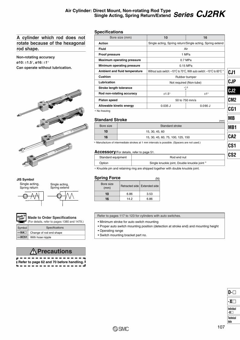
1610Bore size (mm)
Action
Fluid
Proof pressure
Maximum operating pressure
Minimum operating pressure
Ambient and fluid temperature
Cushion
Lubrication
Stroke length tolerance
Rod non-rotating accuracy
Piston speed
Allowable kinetic energy
50 to 750 mm/s
Specifications
±1° ±1.5°
+1.00
∗ No freezing
Bore size
10
16
15, 30, 45, 60
15, 30, 45, 60, 75, 100, 125, 150
Standard Stroke (mm)
Accessory/For details, refer to page 51.
∗ Knuckle pin and retaining ring are shipped together with double knuckle joint.
Single acting, Spring return/Single acting, Spring extend
Air
1 MPa
0.7 MPa
0.15 MPa
Without auto switch: –10°C to 70°C, With auto switch: –10°C to 60°C ∗
Rubber bumper
Not required (Non-lube)
∗ Manufacture of intermediate strokes at 1 mm intervals is possible. (Spacers are not used.)
—XA�—XC51
Change of rod end shape
With hose nipple
Symbol Specifications
(N)Spring Force
1016
6.86
14.2
3.53
6.86
Standard stroke
0.035 J 0.090 J
Refer to page 62 and 70 before handling.
Precautions
• Minimum stroke for auto switch mounting• Proper auto switch mounting position (detection at stroke end) and mounting height• Operating range• Switch mounting bracket part no.
Refer to pages 117 to 123 for cylinders with auto switches.
107
Made to Order Specifications(For details, refer to pages 1380 and 1479.)
Series CJ2RKAir Cylinder: Direct Mount, Non-rotating Rod TypeSingle Acting, Spring Return/Extend
Non-rotating accuracyø10: ±1.5°, ø16: ±1°Can operate without lubrication.
A cylinder which rod does not rotate because of the hexagonal rod shape.
Single acting,Spring extend
JIS SymbolSingle acting,Spring return
Standard equipment
Option
Rod end nut
Single knuckle joint, Double knuckle joint ∗
Bore size(mm)
Retracted side Extended side
CJ1
CJP
CJ2
CM2
CG1
MB
MB1
CA2
CS1
CS2
Individual-X�
D-�
-X�
Technicaldata
P0015-P0124-E.qxd 08.10.2 4:02 PM Page 107

Spring Return10
38
45
54
63
—
—
—
—
16
73
90
112
134
155
198
234
260
10
44
50
59
67
—
—
—
—
16
78
94
114
135
154
192
226
250
(g)
Spring Extend (g)
∗ Rod end nut is included in the mass.
∗ Rod end nut is included in the mass.
Specifications
Action
Max. operating pressure
Min. operating pressure
Cushion
Standard stroke (mm)
Auto switch
Mounting
Single acting, Spring return/Single acting, Spring extend
0.7 MPa
0.15 MPa
Rubber bumper (Standard equipment)
Same as standard type. (Refer to page 107.)
Mountable (Band mounting style)
Bottom mounting style
10, 16Bore size (mm)
Component PartsNo.
12345678
Description Material
Aluminum alloy
Aluminum alloy
Stainless steel
Stainless steel
Brass
Brass
Piano wire
Brass
Note
Anodized
Anodized
Zinc chromated
Rod coverHead coverCylinder tubePiston rodPiston APiston BReturn springSpring seat
No.
91011121314
Description Material
Urethane
Rolled steel
NBR
NBR
NBR
NBR
Note
Nickel plated
BumperRod end nutPiston sealTube gasketPiston gasketRod seal
Mass
108
Series CJ2RK
Bore size (mm)
Mass ∗
15 stroke
30 stroke
45 stroke
60 stroke
75 stroke
100 stroke
125 stroke
150 stroke
15 stroke
30 stroke
45 stroke
60 stroke
75 stroke
100 stroke
125 stroke
150 stroke
Mass ∗
Bore size (mm)
Copper and Fluorine-free Air Cylinder(For CRT manufacturing process)
Eliminates the effects by copper based ions and fluorine based resins, etc. over the color cathode ray tube.Making copper based materials into electroless nickel plated treatment or changing them to the non-copper materials in order to prevent copper ions from generating.
20-CJ2RKA
Copper and fluorine-free
Action Head coverport locationBore size Stroke
Construction (Not able to disassemble)
Single acting, Spring return
Single acting, Spring extend
P0015-P0124-E.qxd 08.10.2 4:03 PM Page 108

(mm)
Y8
8
Bore size
1016
A15
15
B12
18.3
C14
20
GB5
5
H20
20
KA4.2
5.2
L23
26
LB16
20
LDø3.5, ø6.5 counterbore depth 4
ø4.5, ø8 counterbore depth 5
LH8
10
LX12
16
MMM4 x 0.7
M5 x 0.8
NA13.5
13.5
NB9.5
9.5
X28
28
Dimensions by Stroke: Spring Return
1016
S5 to 15
53.5
53.5
16 to 30
61
62
31 to 45
73
74
46 to 60
85
86
61 to 75
–
92
76 to 100
–
116
101 to 125
–
134
126 to 150
–
146
5 to 15
73.5
73.5
16 to 30
81
82
31 to 45
93
94
46 to 60
105
106
61 to 75
–
112
76 to 100
–
136
101 to 125
–
154
126 to 150
–
166
Z
Dimensions by Stroke: Spring Extend (Dimensions not mentioned in the below table are the same as the above table.)
Bore size
1016
GA
16
16
NA
20.5
20.5
NB
5.5
5.5
S5 to 15
56.5
56.5
16 to 30
64
65
31 to 45
76
77
46 to 60
88
89
61 to 75
–
95
76 to 100
–
119
101 to 125
–
137
126 to 150
–
149
5 to 15
76.5
76.5
16 to 30
84
85
31 to 45
96
97
46 to 60
108
109
61 to 75
–
115
76 to 100
–
139
101 to 125
–
157
126 to 150
–
169
Z(mm)
Material: Iron
NTJ-010ANTJ-015A
1016
B
7
8
C
8.19.2
d
M4 x 0.7
M5 x 0.8
H
3.24
B0
–0.3
B0 –0.3
B 0–0.3
109
Series CJ2RKAir Cylinder: Direct Mount, Non-rotating Rod TypeSingle Acting, Spring Return/Extend
Single Acting: Bottom Mounting Style
Spring return: CJ2RK S Head cover port locationBore size Stroke
Head cover port location:Axial location (R)
Spring extend: CJ2RK TBore size Stroke
Rod End Nut
Part no.Applicablebore (mm)
Bore size (mm)
SymbolStroke
Z + 2 x Stroke
Rod end nut
Rod end nut
Breathing hole
Breathing hole
S + Stroke
Piping port M5 x 0.8
Piping port M5 x 0.8
H + Stroke
S + Stroke
Piping port
Rod section
Z + Stroke
X + Stroke
CJ1
CJP
CJ2
CM2
CG1
MB
MB1
CA2
CS1
CS2
Individual-X�
D-�
-X�
Technicaldata
P0015-P0124-E.qxd 08.10.2 4:03 PM Page 109

CDBJ2
CBJ2
With auto switch
With auto switch(Built-in magnet)
Cylinder standard stroke (mm)Refer to the standard stroke table on page 111.
Applicable Auto Switch/Refer to pages 1263 to 1371 for further information on auto switches.
L
L
H
H
N
N
16
16
60
60
Lock positionHR
Head end lock
Rod end lock
Mounting StyleBLFD
Basic style
Axial foot style
Rod side flange style
Double clevis style Note)
Note) Rod end lock only.
Manual releaseN Non-locking type
A96
——
A93A90
C73CC80C
—
M9N—
M9P—
M9B—
H7CM9NW
—M9PW
—M9BW
—H7BAH7NF
—
A72A73—
A80A73CA80CA79W
—F7NV
—F7PV
—F7BVJ79C
—F7NWV
———
F7BWVF7BAV
—
A76H
A72HA73H
—A80H
———
—F79—
F7P—
J79——
F79W—
F7PW—
J79WF7BAF79F
M9BW
CDBJ2B16-45-A
CDBJ2B16-60-BExample
Rail mounting style
Band mounting style
∗ For rail mounting style, screws and nuts for 2 pcs switches come with the rail.
∗ Refer to page 123 for switch mounting brackets.
Nil
Sn
2 pcs.
1 pc.
“n” pcs.
Number of auto switchesAuto switch
∗ For the applicable auto switch model, refer to the table below.
∗ If a built-in magnet cylinder without an auto switch is required, refer to the model of built-in magnet cylinder.
AC
—
200 V
100 V
100 V or less—
24 V or less—
Load voltage
DC
24 V
24 V
5 V
—
12 V
—
5 V, 12 V
12 V
5 V, 12 V
12 V
5 V, 12 V
—
—
Yes
Yes
YesNo
NoYes
Grommet
Grommet
Grommet
Connector
Connector
Grommet
3-wire(NPN equivalent)
2-wire
3-wire (NPN)
4-wire (NPN)
3-wire (NPN)
3-wire (PNP)
3-wire (PNP)
2-wire
2-wire
Relay,PLC
Relay,PLC
IC circuit
IC circuit
IC circuit
IC circuit
IC circuit
IC circuit
(Example) M9NW(Example) M9NWM(Example) M9NWL(Example) M9NWZ(Example) H7CN
∗ Since there are other applicable auto switches than listed, refer to page 123 for details.∗ For details about auto switches with pre-wired connector, refer to pages 1328 and 1329.∗ Band mounting style is not available for D-A9�V�/M9�V�/M9�WV� and D-M9�A(V)L types.
∗ Solid state auto switches marked with “�” are produced upon receipt of order.∗ D-A9�/M9�/M9�W/A7��/A80�/F7��/J7�� auto switches are shipped together (not assembled). (However, when D-A9�/M9�/M9�W types are selected,
only auto switch mounting brackets are assembled before being shipped.)∗ When D-A9�(V)/M9�(V)/M9�W(V) types are mounted on a ø10 or ø16 rail, order auto switch mounting brackets separately. Refer to page 123 for details.
110
Air Cylinder: With End Lock
Series CBJ2ø16
How to Order
Built-in Magnet Cylinder ModelSuffix the symbol “-A” (Rail mounting style) or “-B” (Band mounting style) to the end of part number for cylinder with auto switch.
Type Special function Electricalentry
Indica
tor lig
ht
Ree
d s
wit
chS
olid
sta
te s
wit
ch
Diagnostic indication(2-color indication)
Water resistant (2-color indication)With diagnostic output (2-color indication)
Diagnostic indication (2-color indication)
Wiring(Output)
Lead wire length (m)0.5(Nil)
3(L)
1(M)
5(Z)
None(N)
Applicable loadAuto switch model
Bandmounting
Rail mountingPerpendicular In-line
Pre-wired connector
∗ Lead wire length symbols: 0.5 m········· 1 m········· 3 m········· 5 m········· None·······
NilMLZN
P0015-P0124-E.qxd 08.10.2 4:03 PM Page 110

Action
Fluid
Proof pressure
Maximum operating pressure
Minimum operating pressure
Ambient and fluid temperature
Cushion
Lubrication
Stroke length tolerance
Piston speed
Allowable kinetic energy
50 to 750 mm/s
0.090 J
Specifications
Double acting, Single rod
Air
1 MPa
0.7 MPa
0.15 MPa ∗∗
Without auto switch: –10°C to 70°C, With auto switch: –10°C to 60°C ∗
Rubber bumper
Not required (Non-lube) +1.0
0
∗ No freezing∗∗ 0.06 MPa for parts other than the lock unit.
Lock position
Holding force (Max.)
Lock release pressure
Backlash
Manual release
Lock SpecificationsHead end, Rod end
98 N
0.15 MPa or less
1 mm or less
Non-locking type
∗ Manufacture of intermediate strokes at 1 mm intervals is possible. (Spacers are not used.)
Bore size
16
Standard stroke
Standard Stroke (mm)
15, 30, 45, 60, 75, 100, 125, 150, 175, 200
Series CJ2 air cylinder is equipped with end lock function.
16Bore size (mm)
• Minimum stroke for auto switch mounting• Proper auto switch mounting position (detection at stroke end) and mounting height• Operating range• Switch mounting bracket part no.
Refer to pages 117 to 123 for cylinders with auto switches.
111
Air Cylinder: With End Lock Series CBJ2
CJ1
CJP
CJ2
CM2
CG1
MB
MB1
CA2
CS1
CS2
Individual-X�
D-�
-X�
Technicaldata
P0015-P0124-E.qxd 08.10.2 4:03 PM Page 111

Bolt should be detached under normal operation, otherwise it may cause malfunction of the locking feature.
16
Rubber cap
112
Series CBJ2Specific Product PrecautionsBe sure to read before handling. Please consult with SMC for products outside these specifications.
Use Recommended Air Pressure Circuit.
Caution• It is necessary for proper locking and unlocking.
Operating Pressure
CautionSupply air pressure of 0.15 MPa or higher to the port on the side that has the lock mechanism, as it is necessary for disengaging the lock.
Exhaust Air Speed
CautionThe lock will engage automatically if the air pressure at the port on the side that has the lock mechanism becomes 0.05 MPa or less. Be aware that if the piping on the side that has the lock mechanism is narrow and long, or if the speed controller is located far from the cylinder port, the exhaust air speed could become slower, involving a longer time for the lock to engage. A similar result will ensure if the silencer that is installed on the exhaust port of the solenoid valve becomes clogged.
Manual Disengagement
CautionNon-locking style manual releaseInsert the bolt, which is provided as an accessory part, through the rubber cap (it is not necessary to remove the rubber cap). Screw the bolt into the lock piston and pull the bolt to disengage the lock. Releasing the bolt will re-engage the lock.The bolt size, pulling force, and the stroke are listed below.
Lock Disengagement
CautionTo disengage the lock, make sure to supply air pressure to the port on the side without a lock mechanism, thus preventing the load from being applied to the lock mechanism. (Refer to the recommended air pressure circuit.) If the lock is disengaged when the port on the side that does not contain a lock mechanism is in the exhausted state and the load is being applied to the lock mechanism, undue force will be applied to the lock mechanism, and it may damage the lock mechanism. Also, it could be extremely dangerous, because the piston rod could move suddenly.
Selection
Caution1. Do not use a 3 position solenoid valve.
Avoid using this cylinder in combination with a 3 position solenoid valve (particularly the closed center metal seal type). If air pressure becomes sealed inside the port on the side that contains the lock mechanism, the lock will not engage. Even if the lock is engaged at first, the air that leaks from the solenoid valve could enter the cylinder and cause the lock to disengage as time elapses.
2. Back pressure is necessary for unlocking.Before starting, make sure that air is supplied to the side that is not equipped with a lock mechanism as shown in the diagram above. Otherwise, the lock may not disengage.(Refer to “Rock Disengagement”.)
3. Disengage the lock before installing or adjusting the cyliner.The lock could become damaged if the cylinder is installed with its lock engaged.
4. Operate the cylinder at a load ratio of 50% or less.The lock might not disengage or might become damaged if a load ratio of 50% is exceeded.
5. Do not synchronize multiple cylinders.Do not operate two or more end lock cylinders synchronized to move a single workpiece because one of the cylinder locks may not be able to disengage when required.
6. Operate the speed controller under meter-out control.If operated under meter-in control, the lock might not disengage.
7. On the side that has a lock, make sure to operate at the stroke end of the cylinder.The lock might not engage or disengage if the piston of the cylinder has not reached the stroke end.
8. The position adjustment of the auto switch should be performed at two positions; a position determined by the stroke and a position after the backlash movement (by 1 mm).When a 2-color indication switch is adjusted to show green at the stroke end, the indication may turn red when the cylinder returns by the backlash. This, however, is not an error.
Bore size(mm)
Thread size
M2.5 x 0.45 x 25l or more
Pulling forceN
2
Stroke(mm)
With head end lock With rod end lock
4.9
P0015-P0124-E.qxd 08.10.2 4:03 PM Page 112
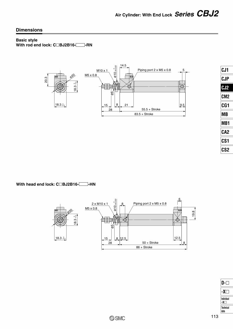
M5 x 0.8
M10 x 1 Piping port 2 x M5 x 0.8
0–0.3
0 –0.3
18.3
ø20
83.5 + Stroke28
15 8
55.5 + Stroke9.5
0h8
-0.0
22ø
10
5
14.5
21
20.3
ø6
M5 x 0.8
2 x M10 x 1 Piping port 2 x M5 x 0.8
0–0.318.3
ø20
2815 8 12.5
ø5
ø5
0h8
-0.0
22ø
10
8
12.5
8
6
19.8
18.3
0
–0.3
18.3
113
Air Cylinder: With End Lock Series CBJ2
Basic styleWith rod end lock: C�BJ2B16- -RN
Dimensions
With head end lock: C�BJ2B16- -HN
50 + Stroke
86 + Stroke
CJ1
CJP
CJ2
CM2
CG1
MB
MB1
CA2
CS1
CS2
Individual-X�
D-�
-X�
Technicaldata
P0015-P0124-E.qxd 08.10.2 4:03 PM Page 113

M5 x 0.8M10 x 1Cover side (Head side)
2 x ø5.5Mounting hole
Cover outside diameter
Cover outside diameter
Piping port 2 x M5 x 0.8
2815 8
2.3
3342
19 20
0–0.318.3
ø20
9.5
514.5
21
20.3
ø6
Piping port 2 x M5 x 0.8
M5 x 0.82 x M10 x 1Cover side (Rod side)
2 x ø5.5Mounting hole 12.5
8
12.550 + Stroke 8
86 + Stroke
6
19.8
2815
ø5
82.3
3342
19 20
0–0.318.3
ø20
18.3
0 –0.3
18.3
0 –0.3
114
Series CBJ2
Flange styleWith rod end lock: C�BJ2F16- -RN
Dimensions
With head end lock: C�BJ2F16- -HN
83.5 + Stroke
55.5 + Stroke
P0015-P0124-E.qxd 08.10.2 4:03 PM Page 114

M5 x 0.8
Cover side (Head side)
2 x ø5.5Mounting hole
M10 x 1
15
8
96
2.3
42
33
14
23 25
28
9.5
5
14.5
21 0–0.318.3
ø20
20.3
ø6
M5 x 0.8
Cover side (Rod side)
2 x ø5.5Mounting hole
2 x M10 x 1
15
8
12.5
ø5
8
96
2.3
42
33
14
23 25
0–0.318.3
ø20
28 8
6
19.8
12.5
0 –0.3
18.3
0 –0.3
18.3
115
Air Cylinder: With End Lock Series CBJ2
Axial foot styleWith rod end lock: C�BJ2L16- -RN
Piping port 2 x M5 x 0.8
83.5 + Stroke
55.5 + Stroke
With head end lock: C�BJ2L16- -HN
Piping port 2 x M5 x 0.8
50 + Stroke
86 + Stroke
CJ1
CJP
CJ2
CM2
CG1
MB
MB1
CA2
CS1
CS2
Individual-X�
D-�
-X�
Technicaldata
P0015-P0124-E.qxd 08.10.2 4:03 PM Page 115

M5 x 0.8
+0.030ø5H9 0
–0.030Clevis pin (ø5d9–0.060 )
28
15 0–0.3
0–0.3
18.3
ø20
23
27.5
8
10
+0.2+0.16.5
14.5
2118.3
ø20
20.3ø
6
0 –0.3
18.3
116
Series CBJ2
Double clevis styleWith rod end lock: C�BJ2D16- -RN
Dimensions
Piping port 2 x M5 x 0.8
101.5 + Stroke
93.5 + Stroke55.5 + Stroke
P0015-P0124-E.qxd 08.10.2 4:03 PM Page 116

D-A9� type
D-C7�/C80 type
D-C73C�/C80C type
D-H7� typeD-H7�W typeD-H7BAL typeD-H7NF type
D-H7C type
BB 22A
17
22A
17
Auto switch
Auto switch
Auto switch
Auto switch
Auto switch
Auto switch
( ): Values for D-A93
(24.5)
≅Hs
≅Hs
≅Hs
≅Hs
D-M9� typeD-M9�W type
Reed Auto Switch <Band mounting type>
Solid State Auto Switch<Band mounting type>
≅Hs
≅Hs
117
Air Cylinder Series CJ2
Proper Auto Switch Mounting Position (Detection at stroke end) and Mounting Height
CJ1
CJP
CJ2
CM2
CG1
MB
MB1
CA2
CS1
CS2
Individual-X�
D-�
-X�
Technicaldata
P0015-P0124-E.qxd 08.10.2 4:03 PM Page 117

D-A7�/A80 type
D-A7�H/A80H type
D-A73C/A80C type
D-A79W type
D-F7�/J79 typeD-F7�W/J79W typeD-F79F/F7BAL type
D-A9� type
D-A9�V type D-M9�V typeD-M9�WV type
D-M9� typeD-M9�W type
D-F7�V/F7�WV typeD-F7BAVL type
D-J79C type
<Rail mounting type> <Rail mounting type>
For the direct mount type, the relation between the auto switch mounting position and the port position is as shown below.
( ): Values for D-A93
12.5 12.5
≅Hs
23.5A B
Auto switch
≅Hs
12.5 12.5 23.5A B
Auto switch
Lead wire min. bending radius 10
Lead wire min. bending radius 10
Auto switch
Auto switch
Auto switch
Auto switch
Auto switch
Auto switch
Auto switch
(26)
14.514.5
≅Hs
21.5A B
Auto switch
≅Hs
12.5 12.5 23.5A B
Auto switch
14.514.5
≅Hs
21.5A B
Port
Auto switch
≅Hs
≅Hs
≅Hs
≅Hs
≅Hs
≅Hs
≅Hs
Lead wire min. bending radius 10
118
Series CJ2
Proper Auto Switch Mounting Position (Detection at stroke end) and Mounting Height
P0015-P0124-E.qxd 08.10.2 4:03 PM Page 118

Proper Auto Switch Mounting Position (Single acting type excluded)Auto switch
model
Bore size
6
1016
A
2.5
3
B
2.5
3
A
1.5
2
B
1.5
2
D-C7�D-C80D-C73CD-C80C
A
6
6.5
B
6
6.5
D-M9�D-M9�W
A
2
2.5
B
2
2.5
Band mounting
2 (8.5)
2 (0.5)
1 (7.5)
1 (0)
5.5(12)
5.5(4)
1.5(8)
1.5(0)
D-A9�
D-H7�D-H7CD-H7NFD-H7�WD-H7BAL
(mm)
Auto switchmodel
Bore size
61016
A—
3
3.5
B—
3
3.5
A—
3.5
4
B—
3.5
4
A—
0.5
1
B—
0.5
1
D-A7�H/A80HD-A73C/A80CD-F7�/J79 D-F7�W/J79WD-F7�V/F7�WVD-F79FD-J79CD-F7BALD-F7BAVL
D-A79W
∗ Figures in parentheses for bore ø6 are for the double rod type (Series CJ2W).∗∗ In the actual setting, adjust them after confirming the auto switch performance.
D-A7�D-A80
A—
8.5
9
B—
8.5
9
D-F7NTL
A—
0.5
1
B—
0.5
1
D-A9�D-A9�V
A—
4.5
5
B—
4.5
5
D-M9�D-M9�VD-M9�WD-M9�WVD-M9�ALD-M9�AVL
(mm)
Rail mounting
Band mounting
Auto Switch Mounting HeightAuto switch
model
Bore size
61016
Hs15
17
20.5
Hs17.5
19.5
23
Hs18
20
23.5
Hs—
16.5
19.5
D-C73CD-C80C D-H7C D-A7�
D-A80
Hs14.5
16.5
20
D-A9�D-M9�D-M9�W
D-C7�/C80D-H7�/H7�WD-H7NFD-H7BAL
(mm)
Rail mountingAuto switchmodel
Bore size
61016
Hs—
17.5
20.5
Hs—
23.5
26.5
Hs—
20
23
Hs—
23
26
D-A73CD-A80C
D-F7�VD-F7�WVD-F7BAVL
D-J79C
Hs—
19
22
D-A79W
Hs—
17.5
21
D-A9�D-A9�VD-M9�D-M9�VD-M9�WD-M9�WVD-M9�ALD-M9�AVL
D-A7�H/A80HD-F7�/J79D-F7�W/J79WD-F7BAL/F79FD-F7NTL
(mm)
119
Air Cylinder Series CJ2
Proper Auto Switch Mounting Position (Detection at stroke end) and Mounting Height
CJ1
CJP
CJ2
CM2
CG1
MB
MB1
CA2
CS1
CS2
Individual-X�
D-�
-X�
Technicaldata
P0015-P0124-E.qxd 08.10.2 4:03 PM Page 119

Proper auto switch mounting position: Spring return type (S)• Standard type (CDJ2���-�S)• Non-rotating rod type (CDJ2K���-�S) • Direct mount type (CDJ2R���-�S)• Non-rotating rod/Direct mount type (CDJ2RK���-�S)
Bore size
6
10
16
6
10
16
6
10
16
6
10
16
10
16
10
16
10
16
10
16
Auto switch model
D-C7�/C80D-C73CD-C80C
D-M9�D-M9�W
D-H7�/H7CD-H7�W/H7BALD-H7NF
D-A7�/A80
D-A9�
D-A79W
D-F7NTL
A Dimensions
16 to 30st
17
16
16.5
21
20
20.5
17.5
16.5
17
16.5
15.5
16
14.5
15
17.5
18
22.5
23
14.5
15
31 to 45st
21
28
28.5
25
32
32.5
21.5
28.5
29
20.5
27.5
28
26.5
27
29.5
30
34.5
35
26.5
27
46 to 60st
35
40
40.5
39
44
44.5
35.5
40.5
41
34.5
39.5
40
38.5
39
41.5
42
46.5
47
38.5
39
61 to 75st
—
—
46.5
—
—
50.5
—
—
47
—
—
46
—
45
—
48
—
53
—
45
76 to 100st
—
—
70.5
—
—
74.5
—
—
71
—
—
70
—
69
—
72
—
77
—
69
101 to 125st
—
—
88.5
—
—
92.5
—
—
89
—
—
88
—
87
—
90
—
95
—
87
126 to 150st B
1.5
2
2.5
5.5
6
6.5
2
2.5
3
1
1.5
2
0.5
1
3.5
4
8.5
9
0.5
1
—
—
100.5
—
—
104.5
—
—
101
—
—
100
—
99
—
102
—
107
—
99
(mm)
D-A7�H/A80HD-A73C/A80CD-F7�/J79 D-F7�W/J79WD-F7�V/F7�WVD-F79F/J79CD-F7BALD-F7BAVL
10 to 15st
8
8.5
8
12
12.5
12
8.5
9
8.5
7.5
8
7.5
7
6.5
D-A9�D-A9�V
D-M9�/M9�VD-M9�W/M9�WVD-M9�AL/M9�AVL
10
9.5
15
14.5
7
6.5
∗ In the actual setting, adjust them after confirming the auto switch performance.
9.5
9
17
17.5
29
29.5
41
41.5
—
47.5
—
71.5
—
89.5
3
3.5
—
101.5
10
16
10
16
18.5
19
30.5
31
42.5
43
—
49
—
73
—
91
4.5
5
—
103
11
10.5
Ban
d m
ount
ing
Rai
l mou
ntin
g
120
Series CJ2Proper Auto Switch Mounting Position (Detection at stroke end) and Mounting HeightSingle Acting, Spring Return Type (S)
P0015-P0124-E.qxd 08.10.2 4:03 PM Page 120

10
16
3.5
4
10
9.5
17.5
18
29.5
30
41.5
42
—
48
—
72
—
102
—
90
6
10
16
6
10
16
6
10
16
6
10
16
10
16
10
16
10
16
D-H7�/H7CD-H7�W/H7BALD-H7NF
10 to 15st
1.5
2
2.5
5.5
6
6.5
2
2.5
3
1
1.5
2
0.5
1
8.5
9
0.5
1
16 to 30st
8
8.5
8
12
12.5
12
8.5
9
8.5
7.5
8
7.5
7
6.5
15
14.5
7
6.5
31 to 45st
17
16
16.5
21
20
20.5
17.5
16.5
17
16.5
15.5
16
14.5
15
22.5
23
14.5
15
46 to 60st
21
28
28.5
25
32
32.5
21.5
28.5
29
20.5
27.5
28
16.5
27
34.5
35
26.5
27
61 to 75st
35
40
40.5
39
44
44.5
35.5
40.5
41
34.5
39.5
40
38.5
39
46.5
47
38.5
39
76 to 100st
—
—
46.5
—
—
50.5
—
—
47
—
—
46
—
45
—
53
—
45
101 to 125st
—
—
69.5
—
—
73.5
—
—
71
—
—
70
—
68
—
77
—
69
126 to 150st
—
—
100.5
—
—
104.5
—
—
101
—
—
100
—
99
—
107
—
99
—
—
88.5
—
—
92.5
—
—
89
—
—
88
—
87
10
16
4.5
5
11
10.5
18.5
19
30.5
31
42.5
43
—
49
—
72
—
103
—
91
—
95
—
87
A
D-A79W
(mm)
D-C7�/C80D-C73CD-C80C
D-M9�D-M9�W
D-A9�
D-A7�/A80
D-A7�H/A80HD-A73C/A80CD-F7�/J79 D-F7�W/J79WD-F7�V/F7�WVD-F79F/J79CD-F7BALD-F7BAVL
D-M9�/M9�VD-M9�W/M9�WVD-M9�AL/M9�AVL
D-A9�D-A9�V
D-F7NTL
10
16
3
3.5
9.5
9
17
17.5
29
29.5
41
41.5
—
47.5
—
71.5
—
101.5
—
87.5
Proper auto switch mounting position: Spring extend type (T)• Standard type (CDJ2���-�T)• Non-rotating rod type (CDJ2K���-�T) • Direct mount type (CDJ2R���-�T)• Non-rotating rod/Direct mount type (CDJ2RK���-�T)
Bore sizeAuto switch modelB Dimensions
∗ In the actual setting, adjust them after confirming the auto switch performance.
Ban
d m
ount
ing
Rai
l mou
ntin
g
121
Air Cylinder Series CJ2Proper Auto Switch Mounting Position (Detection at stroke end) and Mounting HeightSingle Acting, Spring Extend Type (T)
CJ1
CJP
CJ2
CM2
CG1
MB
MB1
CA2
CS1
CS2
Individual-X�
D-�
-X�
Technicaldata
P0015-P0124-E.qxd 08.10.2 4:03 PM Page 121

Minimum Auto Switch Mounting Stroke
D-H7�/H7�WD-H7BALD-H7NF
D-C7�D-C80
D-C73CD-C80CD-H7C
D-M9�V
D-A9�V
D-M9�D-A9�D-M9�WVD-M9�AVL
D-M9�W
D-M9�AL
D-A7�/A80D-A7�H/A80HD-A73C/A80C
D-A9�D-M9�D-M9�W
Auto switch modelAuto switch mounting1 pc.
2 pcs.
Different surfaces
n pcs. (n: No. of auto switch)
No. of auto switch mounted
10 15 Note) Note)
Same surface
45
10 15 50
10 15 60
10 15 65
Same surface
45 + 15 (n-2)
50 + 20 (n-2)
60 + 22.5 (n-2)
50 + 27.5 (n-2)
5 — 5
Band mounting
Rail mounting
(mm)
Different surfaces
—
15 + 35
(n = 2, 4, 6···)
(n-2)2
15 + 40
(n = 2, 4, 6···)
(n-2)2
15 + 45
(n = 2, 4, 6···)
(n-2)2
15 + 50
(n = 2, 4, 6···)
(n-2)2
10 + 10 (n-2)(n = 4, 6···)
5 — 10 —10 + 15 (n-2)(n = 4, 6···)
10 — 10 —15 + 15 (n-2)(n = 4, 6···)
10 — 15 —15 + 15 (n-2)(n = 4, 6···)
15 — 15 —20 + 15 (n-2)(n = 4, 6···)
15 — 20 —20 + 15 (n-2)(n = 4, 6···)
D-A7�HD-A80H
D-A79W
D-F7�D-J79D-F7�VD-J79CD-F7�W/J79WD-F7BAL/F79FD-F7NTLD-F7�WVD-F7BAVL
15 + 15 (n-2)(n = 4, 6···)
15 + 10 (n-2)(n = 4, 6···)
10 + 15 (n-2)(n = 4, 6···)
15 + 15 (n-2)(n = 4, 6···)
10 + 10 (n-2)(n = 4, 6···)
15 + 20 (n-2)(n = 4, 6···)
10 + 15 (n-2)(n = 4, 6···)
5 — 10
5 — 10
10 — 15
5 — 5
5 — 5
10 — 15
10 — 15
—
—
—
—
—
—
—
D-A93
D-M9�D-M9�W
Auto switch model
With 2 auto switches
Different surfaces
—
Less than 20 strokes
Same surface
Less than 50 strokes
Less than 55 strokes
The auto switch is mounted by slightly displacing it in a direction (cylinder tube circumferential exterior) so that the auto switch and lead wire do not interfere with each other.
The proper auto switch mounting position is 5.5 mm inward from the switch holder edge.
Note) When 2 D-A93/M9�/M9�W auto switches are included.
B-5.5
A-5.5
5.5
5.5
B
A15
Auto switchD-M9�D-M9�W
122
Series CJ2
P0015-P0124-E.qxd 08.10.2 4:03 PM Page 122

[Stainless Steel Mounting Screw Kit]The following set of stainless steel mounting screws is available. Use them in accordance with the operating environment. (Since auto switch brackets are not included, order them separately.)
BBA4: For D-C7/C8/H7 types
Note 5) Refer to page 1358 for the details of BBA4 screws. The above stainless steel screws are used when a cylinder is shipped with D-H7BAL-type auto switches.When only a switch is shipped independently, BBA4 screws are attached.
ReferenceAuto switch mounting brackets using stainless steel screws are available for stainless steel cylinder CJ5.
∗ Solid state auto switches are also available with a pre-wired connector. Refer to pages 1328 and 1329 for details.∗ Normally closed (NC = b contact) solid state auto switches (D-F9G/F9H types) are also available. Refer to page 1290 for details.
Auto switch type Part no. FeaturesElectrical entry (Entry direction)
D-C73, C76
D-C80
D-H7A1, H7A2, H7B
D-H7NW, H7PW, H7BW
—
Without light
—
Diagnosis indication (2 colors)
Grommet (In-line)
In addition to the auto switches listed above, the following auto switches are also available.Refer to pages 1263 to 1371 for the detailed specifications.
Reed
Sold state
Operating range
Auto Switch Mounting Brackets for CJ5: Part No.Auto switch mounting bracket part no. NoteBore size (mm)
1016
BJ2-010S
BJ2-016SStainless steel mounting screw
Auto Switch Mounting Bracket: Part No.
Auto switch modelBore size
6 10 164.5
2
6
3
5
—
—
6
2.5
7
4
8
6
3
8
11
7
3
7
4
9
6.5
3.5
9
13
D-A9�
D-C7�/C80/C73C/C80CD-H7�/H7�WD-H7BAL/H7NFD-H7CD-A9�/A9�VD-M9�/M9�VD-M9�W/M9�WVD-M9�AL/M9�ALV
D-A7�/A80/A7H/A80HD-A73C/A80C
D-F7�/J79/F7�W/J79WD-F7�V/F7�WV/F79FD-J79C/F7BAL/F7BAVLD-F7NTL
D-A79W
(mm)
— 5 5
—
—
—
BJ2-006 BJ2-010
Note 3), Note 4)BQ2-012, BQ2-012S
Note 3), Note 4)BQ2-012, BQ2-012S
BJ2-016
Auto switchmounting
Bore size (mm)
ø6 ø10 ø16Auto switch model
Bandmounting
Note 1), Note 2) BJ2-006 BJ3-1
Note 1), Note 2) BJ2-010 BJ3-1
Note 1), Note 2) BJ2-016 BJ3-1
Railmounting
D-A9�D-M9�D-M9�W
D-C7�/C80D-C73C/C80CD-H7�/H7�WD-H7BAL/H7NF
D-A9�D-A9�VD-M9�D-M9�VD-M9�WD-M9�WVD-M9�AL (4)
D-M9�AVL (4)
BQ2-012BQ2-012S
D-M9�D-M9�W
BJ2-���: A set of a and b aboveBJ3-1: A set of c, d and e above
Auto switch
Set screw (Not used)
Switch spacer(Stainless steel)
eSwitch holder
(Resin)
d
Switch bracket(Stainless steel)
c
Auto switch mounting screwb
Auto switch mounting banda
Ban
d m
ount
ing
Rai
l mou
ntin
g
123
∗ Since this is a guideline including hysteresis, not meant to be guaranteed. (Assuming approximately ±30% dispersion.) There may be the case it will vary substantially depending on an ambient environment.
Air Cylinder Series CJ2
Note 1) Two kinds of auto switch bracket are used as a set.Note 2) When cylinders are shipped, only auto switch mounting brackets are assembled. Note 3) When a compact auto switch is mounted on a ø10 or ø16 rail, an auto switch bracket is needed, to be
ordered separately.CDJ2B10-60-A······1D-M9BWV·············2 pcs.BQ2-012 ···············2 pcs.
Note 4) For D-M9�A(V)L, order BQ2-012S, which uses stainless steel mounting screws.
CJ1
CJP
CJ2
CM2
CG1
MB
MB1
CA2
CS1
CS2
Individual-X�
D-�
-X�
Technicaldata
P0015-P0124-E.qxd 08.10.2 4:03 PM Page 123

How to Order
CJ2X
With auto switch 16
16
CDJ2X L
L
With auto switch(Built-in magnet)
Low speed cylinder
Standard stroke (mm)ø10ø16
15, 30, 45, 60, 75, 100, 125, 150
15, 30, 45, 60, 75, 100, 125, 150, 175, 200
∗ Intermediate stroke other than above is manufactured upon receipt of order.
Nil
Sn
2 pcs.
1 pc.
“n” pcs.
Number of auto switchesPort location on head cover
∗ For configuration, refer to page 1115.
Nil
RPerpendicular to axis
Axial direction
ø10, ø16Bore size
(mm)Symbol
Mounting styleBLFD
Basic style
Axial foot style
Rod side flange style
Double clevis style
Bore size1016
10 mm
16 mm
∗ For the applicable auto switch model, refer to the table below.
60
60
Built-in Magnet Cylinder Model
CDJ2XB10-45-A
CDJ2XB16-60-BExample
Rail mounting style
Band mounting style
Suffix the symbol “-A” (Rail mounting style) or “-B” (Band mounting style) to the end of part number for cylinder with auto switch.
∗ For the rail mounting type, screws and nuts for two auto switches are included in the rail.
M9BW
Auto switchNil Without auto switch
Applicable Auto Switch/Refer to pages 1719 to 1827 for further information on auto switches.
Yes
NoYesNoYes
Yes
Type
Ree
d s
wit
chS
olid
sta
te s
wit
ch
Special functionElectrical
entry
Grommet
Grommet
Grommet
Connector
Connector
Grommet
—200 V
100 V
100 V or less—
24 V or less—
Wiring(Output)
3-wire(NPN equivalent)
2-wire
3-wire (NPN)
3-wire (PNP)
2-wire
3-wire (NPN)
3-wire (PNP)
2-wire
4-wire (NPN)
Load voltage
DC
24 V
24 V
5 V
—
12 V
—
5 V, 12 V
12 V
5 V, 12 V
12V
5 V, 12 V
AC
Lead wire length (m)
0.5(Nil)
�
�������
��������������
3(L)
�
�������
��������������
1(M)
—
———————
�—
�—
�——
�—
�—
�——
5(Z)
—
—
�——
��—
��������������
None(N)
—
————
��—
——————
�———————
—
———————
������—
�������
Applicable loadPre-wiredconnector
IC circuit
—
IC circuit—
IC circuit—
IC circuit
—
IC circuit
—
IC circuit
Relay,PLC
Relay,PLC
Auto switch model
Bandmounting
Rail mountingPerpendicular In-line
Diagnostic indication(2-color indication)
With diagnostic output (2-color indication)
Diagnostic indication(2-color indication)
A96
——
A93A90
C73CC80C
—
M9N—
M9P—
M9B—
H7CM9NW
—M9PW
—M9BW
—H7NF
—
A72A73—
A80A73CA80CA79W
—F7NV
—F7PV
—F7BVJ79C
—F7NWV
———
F7BWV—
A76H
A72HA73H
—A80H
———
—F79—
F7P—
J79——
F79W—
F7PW—
J79WF79F
——
—
∗ Lead wire length symbols: 0.5 m ············ Nil (Example) M9NW 1 m ············ M (Example) M9NWM 3 m ············ L (Example) M9NWL 5 m ············ Z (Example) M9NWZ
∗ Since there are other applicable auto switches than listed, refer to page 1123 for details.∗ For details about auto switches with pre-wired connector, refer to pages 1784 and 1785.∗ For the band mounting type, D-A9�V�/M9�V�/M9�WV�/M9�A(V)L types cannot be mounted.
∗ Solid state auto switches marked with “�” are produced upon receipt of order.∗ D-A9�/M9�/M9�W/A7��/A80�/F7��/J7�� auto switches are shipped together (not assembled). (When D-A9�/M9�/M9�W are specified, only auto switch mounting
brackets are assembled before shipped.)∗ D-C7��/C80�/H7�� auto switches are assembled at the time of shipment.∗ Order auto switch mounting brackets separately when D-A9�(V)/M9�(V)/M9�W(V) types are mounted with a rail. Refer to page 1123 for details.
—
—
Indica
tor lig
ht
1114
Low Speed CylinderDouble Acting, Single Rod
ø10, ø16Series CJ2X
P1111-P1166-E.qxd 08.11.17 3:24 PM Page 1114

Action
Fluid
Proof pressure
Maximum operating pressure
Minimum operating pressure
Ambient and fluid temperature
Cushion
Lubrication
Stroke length tolerance
Piston speed
Allowable kinetic energyø10
ø16
Specifications
Double acting, Single rod
Air
1.05 MPa
10.7 MPa
0.06 MPa
+1.0 0
Bore size (mm)
10
16
Bore size (mm) 10 16
Standard stroke (mm)
15, 30, 45, 60, 75, 100, 125, 150
15, 30, 45, 60, 75, 100, 125, 150, 175, 200
Standard Stroke
Mounting Style and Accessory
Port Location on Head Cover
Mounting Bracket Part No.
Precautions
1. During installation, secure the rod cover and tighten by applying an appropriate tightening force to the retaining but or to the rod cover body.If the head cover is secured or the head cover is tightened, the cover could rotate, leading to the deviation.
2. Proper tightening torque for mounting thread should be within the range specified. Apply a Loctite® (no. 242 Blue) for mounting thread.
3. To remove and install the retaining ring for the knuckle pin or the clevis pin, use an appropriate pair of pliers (tool for installing a type C retaining ring). Especially with ø10, use ultra thin pliers, such as Super Tool Corp., CSM-07A.
4. For the auto switch mounting rail, do not remove the pre-equipped rail. Since the mounting thread is drilled through inside a the cylinder, it will result in air leakage.
Mounting
Caution
1. It might not be able to control by meter-out at a low speed operation.
Operating Precautions
Warning
1. For Series CJ2X, 0.1 N l /min is the values at maximum in terms of its construction and there is internal leakage (ANR).
Caution
∗ Pin and retaining ring are shipped together with double clevis and double knuckle joint.
∗ Manufacture of intermediate strokes at 1 mm intervals is possible. (Spacers are not used.)
Mounting
Mounting nut
Rod end nut
Clevis pin
Single knuckle joint
Double knuckle joint∗
T-bracket
��
��
��
��
��
��
�����
Basicstyle
Axial footstyle
Rod sideflange style
Double∗
clevis style
Mountingbracket
Foot bracketFlange bracketT-bracket∗
Bore size (mm)
10CJ-L010BCJ-F010BCJ-T010B
16CJ-L016BCJ-F016BCJ-T016B
∗ T-bracket is used with double clevis (D).
For basic style, the port position in a head cover is available either perpendicular to the axis or in-line with the cylinder axis.
Axial direction Perpendicular
Bore size(mm)
Proper tightening torque for mounting thread(N·m) (tightening torque for mounting nut)
1016
3.0 to 3.2
5.4 to 5.9
Without auto switch: –10 to 70°C (No freezing)With auto switch: –10 to 60°C (No freezing)
Rubber bumper (Standard equipment)
Not required (Non-lube)
1 to 300 mm/s
0.035 J
0.090 J
JIS Symbol
Double acting, Single rod
Be sure to read before handling.Refer to front matters 42 and 43 for Safety Instructions and pages 3 to 11 for Actuator and Auto Switch Precau-tions.
Sta
ndar
deq
uipm
ent
Opt
ion
1115
Series CJ2XLow Speed CylinderDouble Acting, Single Rod
REA
REB
REC
C�Y
C�X
MQ
RHC
RZQ
Individual-X�
D-�
-X�
P1111-P1166-E.qxd 08.11.17 3:24 PM Page 1115

Axial Foot Style (L)
CJ2XL10, 16
CJ2XL
B0
-0
.3
∗ For details of the mounting nut, refer to page 1118.
Basic Style (B)
CJ2XB
Port location on head cover: Axial location (R)
Port location on head cover: Axial location (R)
CJ2XB10, 16
B 0 -0
.3
∗ For details of the mounting nut, refer to page 1118.
Z74
75
Bore size (mm)
1016
A15
15
B12
18.3
C14
20
D4
5
F8
8
GA8
8
GB5
5
H28
28
MMM4 x 0.7
M5 x 0.8
NA12.5
12.5
NB9.5
9.5
NDh8 NNM8 x 1.0
M10 x 1.0
S46
47
T—
—
0–0.022
0–0.022
8
10
Bore size (mm)
1016
A15
15
B12
18.3
C14
20
D4
5
F8
8
GA8
8
GB5
5
H28
28
LB15
23
LC4.5
5.5
LH9
14
LT1.6
2.3
LX24
33
LY16.5
25
LZ32
42
MMM4 x 0.7
M5 x 0.8
NA12.5
12.5
NB9.5
9.5
NNM8 x 1.0
M10 x 1.0
S46
47
T—
—
X5
6
Y7
9
Z74
75
Bore size Stroke Port location on head cover
Bore size Stroke Port location on head cover
Mounting nut ∗
Rod end nut
Mounting nut ∗
Rod end nut
Piping port 2 x M5 x 0.8
Piping port 2 x M5 x 0.8
Piping port M5 x 0.8
Piping port M5 x 0.8
S + Stroke
Z + Stroke
S + Stroke
Z + Stroke
Cover surface
(mm)
1116
Series CJ2X
P1111-P1166-E.qxd 08.11.17 3:24 PM Page 1116

Rod Side Flange Style (F)
CJ2XF
CJ2XF10, 16
B0
-0
.3
Double Clevis Style (D)
CJ2XD
∗ Clevis pin and retaining ring are shipped together.
B0
-0
.3
CZ
0
-0.3
∗ For details of the mounting nut, refer to page 1118.
Bore size (mm)
1016
A15
15
Bore size (mm)
1016
TC4.5
5.5
TH29
35
TV40
48
TW22
28
TX32
38
TY12
16
B12
18.3
C14
20
CD (cd)3.3
5
CX3.2
6.5
CZ12
18.3
D4
5
GA8
8
GB18
23
H28
28
MMM4 x 0.7
M5 x 0.8
NA12.5
12.5
NB22.5
27.5
R5
8
S46
47
U8
10
Z82
85
ZZ93
99
T-bracket Dimensions
Bore size (mm)
1016
A15
15
B12
18.3
C14
20
D4
5
F8
8
FB13
19
FC4.5
5.5
FT1.6
2.3
FX24
33
FY14
20
FZ32
42
GA8
8
GB5
5
H28
28
MMM4 x 0.7
M5 x 0.8
NNM8 x 1.0
M10 x 1.0
NA12.5
12.5
NB9.5
9.5
S46
47
T—
—
Z74
75
For details, refer to page 1118.
Bore size Stroke Port location on head cover
Bore size Stroke
Cover surface
Mounting hole
Mounting nut ∗Rod end nut
Piping port 2 x M5 x 0.8
Piping portM5 x 0.8
S + Stroke
Z + Stroke
Z + Stroke
S + Stroke
ZZ + Stroke
Port location on head cover: Axial location (R)
T-bracket
Rod end nut
Piping port 2 x M5 x 0.8 Clevis pin
1117
Series CJ2XLow Speed CylinderDouble Acting, Single Rod
(mm)
(mm)
(mm)
REA
REB
REC
C�Y
C�X
MQ
RHC
RZQ
Individual-X�
D-�
-X�
P1111-P1166-E.qxd 08.11.17 3:24 PM Page 1117

4 x øTC
Accessory Bracket Dimensions (mm)
Single Knuckle Joint Clevis Pin Knuckle Pin
Double Knuckle Joint
T-bracket Rod End Cap
Mounting Nut Rod End Nut
Part no. A1 L1 MM NXNDH10
I-J010B
I-J016B
10
16
8
8
21
25
3.1
6.4
R1
8
12
U1
9
14
M4 x 0.7
M5 x 0.8
Applicablebore Part no.
CD-J010
IY-J015
10
16
Applicablebore
Part no. Dd9
CD-J010
CD-Z015
10
16
d
3
4.8
L
15.2
22.7
l
12.2
18.3
m
1.2
1.5
t
0.3
0.7
Type C 3.2
Type C 5
Applicablebore
Applicable retaining ring
3.3
5.3
+0.0480
+0.048 0
3.3
5.3
–0.030–0.060
–0.030–0.060
∗ Retaining rings are packaged with clevis pins. ∗ For size ø10, clevis pin is diverted. ∗ Retaining rings are packaged with knuckle pins.
Material: Rolled steel Material: Stainless steel Material: Stainless steel
Dd9 d
3
4.8
L
15.2
16.6
l
12.2
12.2
m
1.2
1.5
t
0.3
0.7
Type C 3.2
Type C 5
Applicable retaining ring
Part no.Y-J010B
Y-J016B
10
16
Part no. B
SNJ-010B
SNJ-016B
10
16
11
14
C
12.7
16.2
d
M8 x 1.0
M10 x 1.0
H
4
4
Applicablebore
Material: Rolled steel Material: Brass
Applicable bore A1
8
11
Part no.
Y-J010B
Y-J016B
NDd9 NDH10
L15.2
16.6
NX3.2
6.5
R1
8
12
U1
10
10
L1
21
21
MMM4 x 0.7
M5 x 0.8
3.3
5
–0.030–0.060
–0.030–0.060
3.3
5
+0.0480
+0.048 0
Part no. B
NTJ-010A
NTJ-015A10
16
7
8
C
8.1
9.2
d
M4 x 0.7
M5 x 0.8
H
3.2
4
Applicablebore
Material: Iron
∗ Knuckle pin and retaining ring are shipped together.
Part no.
CJ-T010B
CJ-T016B
10
16
TC
4.5
5.5
TH
29
35
TK
18
20
TN
3.1
6.4
TT
2
2.3
TU
9
14
TV
40
48
TW
22
28
TX
32
38
TY
12
16
TZ
8
10
Applicablebore TDH10
3.3
5
+0.0480
+0.048 0
Part no.
Flat type
CJ-CF010
CJ-CF016
ApplicableboreRound type
CJ-CR010
CJ-CR016
10
16
A
8
10
D
10
12
L
13
15
R
10
12
N
6
7
W
8
10
MM
M4 x 0.7
M5 x 0.8
Material: Polyacetal
Flat type/CJ-CF��� Round type/CJ-CR���
1212
3.3
5.3
–0.030–0.060
–0.030–0.060
Double clevis style cylinder
∗ T-bracket includes a T-bracket base, single knuckle joint, hexagon socket head capscrew and spring washer.
hole
axis
1118
Series CJ2X
P1111-P1166-E.qxd 08.11.17 3:24 PM Page 1118

D-C7�/C80
D-C73C�/C80C
D-H7�D-H7�WD-H7NF
D-H7C
17
≅ Hs
≅ Hs
D-M9�D-M9�W
Solid state auto switch<Band mounting style>
B22A
Auto switch
Auto Switch Proper Mounting Position (Detection at Stroke End) and Its Mounting Height
D-A9�
B22A
17
Auto switch
Auto switchAuto switch
Auto switchAuto switch
( ): For D-A93 type
(24.5)
≅ Hs
≅ Hs
≅ Hs ≅ Hs
Reed auto switch<Band mounting style>
1119
Series CJ2XLow Speed CylinderDouble Acting, Single Rod
REA
REB
REC
C�Y
C�X
MQ
RHC
RZQ
Individual-X�
D-�
-X�
P1111-P1166-E.qxd 08.11.17 3:24 PM Page 1119

23.5A B
Auto switch
Auto switch
Auto switch
Auto switch
Auto switch
Reed auto switch<Band mounting style>
D-A7�/A80
D-A9�
D-A9�V
D-A7�H/A80H
D-A73C/A80C
D-A79W
( ): For D-A93 type
12.5 12.5
≅ H
s≅
Hs
≅ H
s
≅ Hs
≅ H
s≅
Hs
12.5 12.5 23.5A B
Auto switch
(26)
Minimum lead wirebending radius 10
Minimum lead wirebending radius 10
Minimum lead wire bending radius 10
≅ H
s
≅ H
s≅ H
s
Auto switch
Auto switch
Auto switch
D-F7�/J79D-F7�W/J79WD-F79F
D-F7�V/F7�WV
D-J79C
Solid state auto switch<Band mounting style>
D-M9�D-M9�W
D-M9�V D-M9�WV
14.514.5
≅ H
s
21.5A B
Auto switch
≅ H
s
12.5 12.5 23.5A B
Auto switch
Auto Switch Proper Mounting Position (Detection at Stroke End) and Its Mounting Height
1120
Series CJ2X
P1111-P1166-E.qxd 08.11.17 3:24 PM Page 1120

Auto Switch Proper Mounting Position
Auto Switch Mounting Height
Auto switchmodel
Auto switchmodel
Boresize (mm)
Band mounting Rail mounting
Band mounting Rail mounting
Boresize (mm)
1016
1016
Hs17
20.5
Hs19.5
23
Hs20
23.5
Hs16.5
19.5
Hs23
26
Hs19
22
A2
2.5
B2
2.5
D-A9�
A6
6.5
B6
6.5
A2.5
3
B2.5
3
D-M9�D-M9�W
D-C7�D-C80D-C73CD-C80C
D-M9�D-M9�VD-M9�WD-M9�WV
A1.5
2
B1.5
2
D-H7�D-H7CD-H7NFD-H7�W
D-A79WD-F7NTL
Note) Adjust the auto switch after confirming the operating conditions in the actual setting.
D-C73CD-C80C D-H7C D-A7�
D-A80
Hs16.5
20
D-A9�D-M9�D-M9�W
D-J79C D-A79W
A0.5
1
B0.5
1
D-A9�D-A9�V
D-A7�D-A80
A4.5
5
B4.5
5
A3
3.5
B3
3.5
D-A7�H/A80HD-A73C/A80CD-F7�/J79 D-F7�W/J79WD-F7�V/F7�WVD-F79FD-J79C
A3.5
4
B3.5
4
A8.5
9
B8.5
9
A0.5
1
B0.5
1
Hs17.5
20.5
Hs23.5
26.5
Hs20
23
D-A7�H/A80HD-F7�/J79D-F7�W/J79WD-F79FD-F7NTL
Hs17.5
21
D-A9�D-A9�VD-M9�D-M9�VD-M9�WD-M9�WV
D-A73CD-A80C
D-F7�VD-F7�WV
D-C7�D-C80D-H7�D-H7�WD-H7NF
Auto Switch Proper Mounting Position (Detection at Stroke End) and Its Mounting Height
(mm)
(mm)
1121
Series CJ2XLow Speed CylinderDouble Acting, Single Rod
REA
REB
REC
C�Y
C�X
MQ
RHC
RZQ
Individual-X�
D-�
-X�
P1111-P1166-E.qxd 08.11.17 3:24 PM Page 1121

Minimum Auto Switch Mounting Stroke
D-H7�/H7�WD-H7NF
D-C7�D-C80
D-C73CD-C80CD-H7C
D-A7�/A80D-A7�H/A80HD-A73C/A80C
D-A9�D-M9�D-M9�W
Auto switch mounting Auto switch model1 pc.
2 pcs.
Different surfaces
n pcs. (n: No. of auto switch)
No. of auto switch mounted
10 15 Note) Note)
Same surface
45
10 15 50
10 15 60
10 15 65
Same surface
45 + 15 (n-2)
50 + 20 (n-2)
60 + 22.5 (n-2)
50 + 27.5 (n-2)
Band mounting
Rail mounting
(mm)
Different surfaces
15 + 35
(n = 2, 4, 6···)
(n-2)2
15 + 40
(n = 2, 4, 6···)
(n-2)2
15 + 45
(n = 2, 4, 6···)
(n-2)2
15 + 50
(n = 2, 4, 6···)
(n-2)2
D-A7�HD-A80H
D-A79W
D-F7�D-J79D-F7�VD-J79CD-F7�W/J79WD-F79FD-F7NTL
D-F7�WV
15 + 15 (n-2)(n = 4, 6···)
15 + 10 (n-2)(n = 4, 6···)
10 + 15 (n-2)(n = 4, 6···)
15 + 15 (n-2)(n = 4, 6···)
10 + 10 (n-2)(n = 4, 6···)
15 + 20 (n-2)(n = 4, 6···)
10 + 15 (n-2)(n = 4, 6···)
5 — 10
5 — 10
10 — 15
5 — 5
5 — 5
10 — 15
10 — 15
—
—
—
—
—
—
—
D-A93
D-M9�D-M9�W
Auto switch model
With 2 auto switches
Different surfaces
—
Less than 20 strokes
Same surface
Less than 50 strokes
Less than 55 strokes
The auto switch is mounted by slightly displacing it in a direction (cylinder tube circumferential exterior) so that the auto switch and lead wire do not interfere with each other.
The proper auto switch mounting position is 5.5 mm inward from the switch holder edge.
Note) When 2 D-A93/M9�/M9�W auto switches are included.
B-5.5
A-5.5
5.5
5.5
B
A15
Auto switchD-M9�D-M9�W
D-M9�V
D-A9�V
D-M9�D-A9�
D-M9�WV
D-M9�W
5 — 5 —10 + 10 (n-2)(n = 4, 6···)
5 — 10 —10 + 15 (n-2)(n = 4, 6···)
10 — 10 —15 + 15 (n-2)(n = 4, 6···)
10 — 15 —15 + 15 (n-2)(n = 4, 6···)
15 — 15 —20 + 15 (n-2)(n = 4, 6···)
1122
Series CJ2X
P1111-P1166-E.qxd 08.11.17 3:24 PM Page 1122

∗ With pre-wired connector is available for solid state auto switches. For details, refer to pages 1784 to 1785.∗ Normally closed (NC = b contact), solid state auto switches (D-F9G, F9H type) are also available. For details, refer to page
Auto switch type Model FeaturesElectrical entry (Direction)
D-C73, C76
D-C80
D-H7A1, H7A2, H7B
D-H7NW, H7PW, H7BW
—
Without indicator light
—
Diagnostic indication (2-color indication)
Grommet (in-line)
Other than the applicable auto switches listed in “How to Order”, the following auto switches can be mounted. For detailed specifications, refer to pages 1719 to 1827.
Reed
Solid state
Operating Range Auto Switch Mounting Bracket/Part No.
Note 1) Two kinds of auto switch mounting brackets are used as a set.Note 2) Auto switch mounting brackets are shipped together with cylinders.Note 3) When mounting a compact auto switch on the ø10 or ø16 rail mounting type, order auto switch
mounting bracket shown in the table above. Order it separately from the cylinder.ExampleCDJ2BX10-60-A ····· 1 unitD-M9BWV ····· 2 pcs.BQ2-012 ····· 2 pcs.
Auto switch modelBore size (mm)
10 16 6
2.5
7
4
8
6
3
8
11
7
3
7
4
9
6.5
3.5
9
13
D-A9�
D-C7�/C80/C73C/C80CD-H7�/H7�WD-H7NFD-H7CD-A9�/A9�V
D-M9�/M9�VD-M9�W/M9�WV
D-A7�/A80/A7H/A80HD-A73C/A80C
D-F7�/J79/F7�W/J79WD-F7�V/F7�WV/F79FD-J79CD-F7NTL
D-A79W
5 5
BJ2-010
Note 3)
BQ2-012Note 3)
BQ2-012
BJ2-016
D-M9�D-M9�W
Auto switchmounting
Bore size
ø10 ø16Auto switch model
Bandmounting
Note 1), Note 2)
qBJ2-010 wBJ3-1Note 1), Note 2)
qBJ2-016 wBJ3-1
Railmounting
D-A9�D-M9�D-M9�W
D-C7�/C80D-C73C/C80CD-H7�/H7�WD-H7NF
D-A9�D-A9�VD-M9�D-M9�VD-M9�WD-M9�WV
BQ2-012
qBJ2-���: A set of a and b in the figure.wBJ3-1: A set of c, d and e in the figure.
Auto switch
Set screw (not used)
Switch spacer(Stainless steel)
e
Auto switch mounting screwb
Auto switch mounting banda
Switch holder(Resin)
d
Switch bracket(Stainless steel)
cBan
d m
ount
ing
Rai
l mou
ntin
g
∗ Since this is a guideline including hysteresis, not meant to be guaranteed.(Assuming approximately ±30% dispersion.)There may be the case it will vary substantially depending on an ambient environment.
(mm)
1123
Series CJ2XLow Speed CylinderDouble Acting, Single Rod
REA
REB
REC
C�Y
C�X
MQ
RHC
RZQ
Individual-X�
D-�
-X�
P1111-P1166-E.qxd 08.11.17 3:24 PM Page 1123
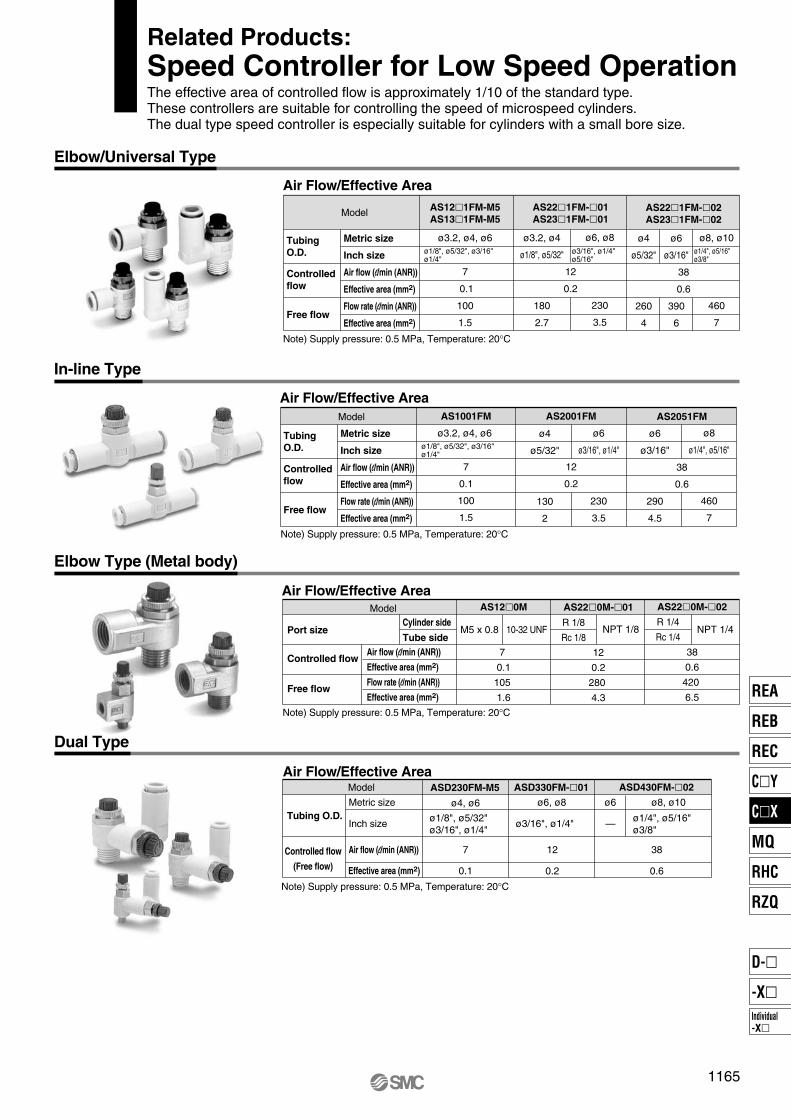
ø1/8", ø5/32", ø3/16"ø1/4"
TubingO.D.
Controlled flow
Free flow
ø4
ø5/32"
130
2
ø6
ø3/16", ø1/4"
230
3.5
ø6
ø3/16"
290
4.5
ø8
ø1/4", ø5/16"
460
7
Note) Supply pressure: 0.5 MPa, Temperature: 20°C
Model AS1001FM
ø3.2, ø4, ø6
7
0.1
100
1.5
AS2001FM
12
0.2
AS2051FM
38
0.6
Metric size
Inch size
Air flow (l/min (ANR))
Effective area (mm2)
Flow rate (l/min (ANR))
Effective area (mm2)
Elbow/Universal Type
In-line Type
Elbow Type (Metal body)
Dual Type
Air Flow/Effective Area
ø1/8", ø5/32", ø3/16"ø1/4"
ø3/16", ø1/4"ø5/16"
TubingO.D.
Controlled flow
Free flow
ø3.2, ø4
ø1/8", ø5/32"
180
2.7
ø6, ø8
230
3.5
ø4
ø5/32"
260
4
ø6
ø3/16"
390
6
ø8, ø10
460
7
Note) Supply pressure: 0.5 MPa, Temperature: 20°C
Model AS12�1FM-M5 AS13�1FM-M5
ø3.2, ø4, ø6
7
0.1
100
1.5
AS22�1FM-�01AS23�1FM-�01
12
0.2
AS22�1FM-�02AS23�1FM-�02
38
0.6
Metric size
Inch size
Air flow (l/min (ANR))
Effective area (mm2)
Flow rate (l/min (ANR))
Effective area (mm2)
ø1/4", ø5/16"ø3/8"
Air Flow/Effective Area
Air Flow/Effective Area
Port size
Controlled flow
Free flow
Note) Supply pressure: 0.5 MPa, Temperature: 20°C
Cylinder side
Tube side
Model
Air flow (l/min (ANR))
Effective area (mm2)
Flow rate (l/min (ANR))
Effective area (mm2)
AS12�0M
7
0.1
105
1.6
AS22�0M-�01
12
0.2
280
4.3
AS22�0M-�02
38
0.6
420
6.5
M5 x 0.8 10-32 UNF NPT 1/8 NPT 1/4R 1/8
Rc 1/8
R 1/4
Rc 1/4
Air Flow/Effective Area
Note) Supply pressure: 0.5 MPa, Temperature: 20°C
Model
Tubing O.D.
Controlled flow
(Free flow)
Metric size
Inch size
Air flow (l/min (ANR))
Effective area (mm2)
ASD230FM-M5 ASD330FM-�01 ASD430FM-�02
ø4, ø6
7
0.1
ø6, ø8
12 38
0.60.2
ø8, ø10ø6
ø1/8", ø5/32"ø3/16", ø1/4"
ø1/4", ø5/16"ø3/8"
ø3/16", ø1/4" —
Related Products:Speed Controller for Low Speed OperationThe effective area of controlled flow is approximately 1/10 of the standard type. These controllers are suitable for controlling the speed of microspeed cylinders. The dual type speed controller is especially suitable for cylinders with a small bore size.
1165
REA
REB
REC
C�Y
C�X
MQ
RHC
RZQ
Individual-X�
D-�
-X�
P1111-P1166-E.qxd 08.11.17 3:25 PM Page 1165

Recommended Pneumatic Circuit
Speed is controlled by meter-out circuit. Using concurrently the meter-in circuit can alleviate the stick-slip. More stable low speed operation can be achieved than meter-in circuit alone.
Warning
Dual speed controller
Horizontal Operation
�
Meter-in speed controllers can reduce lurching while controlling the speed. The two adjustment needles facilitate adjustment.
Meter-in speed controller
��
Vertical Operation
� ��
Warning
∗ ∗
∗
∗
∗
∗W
WA
AP1
P0
P0
P2
a
a
Selection Pneumatic Circuit
Caution Caution1. Operate within the standard strokes.
Operating with the stroke exceeding the standard stroke may cause malfunction.
2. Provide a construction that does not apply a lateral load to the cylinder.Applying a lateral load to the cylinder may cause malfunction.
3. Do not use the product at a high frequency.Use it at 30 cpm or less as a guideline.
4. Do not wipe out the grease in the sliding part of the air cylinder.Doing so forcefully may cause malfunction.
1. The piping length between the speed controller and the cylinder port must be kept as short as possible.If the speed controller and the cylinder port are far apart, speed adjustment may be unstable.
2. Use a low speed controller to easily adjust for low speed operation or a dual speed controller (Series ASD) to prevent cylinders from popping out.(When the low speed controller is used, the maximum speed may be limited.)
Low Speed CylinderSpecific Product PrecautionsBe sure to read before handling.Refer to front matters 42 and 43 for Safety Instructions and pages 3 to 11 for Actuator and Auto Switch Precautions.
(c)
(b)
(1) Speed is controlled by meter-out circuit. Using concurrently the meter-in circuit can alleviate the stick-slip.∗
(2) Depending on the size of the load, installing a regulator with check valve at position (b) can deduce lurching during descent and operation delay during ascent.As a guide,when W + P0a>P0A,adjust P1 to make W + P1a = P0A.
(1) Speed is controlled by meter-out circuit. Using concurrently the meter-in circuit can alleviate the stick-slip.∗
(2) Installing a regulator with check valve at position (c) can reduce lurching during descent and operation delay during ascent.As a guide,adjust P2 to make W + P2A = P0a.
W: Load (N) P0: Operating pressure (MPa) P1, P2: Reduced pressure (MPa) a: Rod side piston area (mm2) A: Head side piston area (mm2)
Since C�J2X, C�UX10 are subject to internal leakage due to their construction, the speed may not be fully controlled with the meter-out controller (∗) during low speed operation.
1166
P1111-P1166-E.qxd 08.11.17 3:25 PM Page 1166

Locking in both directions is possible.Locking in either side of cylinder stroke is possible, too.(The lock-up cylinder can be locked only in one direction.)
(Lock-up cylinders are spring locking only.)
Series
Series CLJ2
Series CLM2
Series CLG1
Lock-up cylinderSeries CL1
Action
Doubleacting
Doubleacting
Doubleacting
Doubleacting
Rod Locking method
16
20253240
20
253240
40
50, 63
80, 100
125, 140
160
15
200 to
to
to
25
300
25 to 200
25
300
25 to 500
25 to 600
25 to 700
Up to 1000
Up to 1200
601
611
625
636
Series CLFine Lock Cylinders/Lock-up Cylinder
ø16, ø20, ø25, ø32, ø40, ø50, ø63, ø80, ø100, ø125, ø140, ø160
Locking
method
Features
Springlocking
• UnlockingDischarging
the air causes
the lock to
operate.
Pneumaticlocking
Spring and
pneumatic locking
• Pressure locking The holding
power can be
varied according
to the air
pressure that is
applied to the
port.
• Pressure lockingThe holding power can be var ied according to the air pressure that is applied to the port.
• UnlockingDischarging the air causes the lock to operate.
Series Variations
Fine lock cylinders
Singlerod
Singlerod
Singlerod
Singlerod
Standard variations
Auto switchbuilt-in magnet
With rod boot
Lockingdirection
Bothdirections
Bothdirections
Bothdirections
Onedirection
Springlocking
Pneumaticlocking
Spring andPneumatic locking
Bore size(mm)
Standardstroke(mm)
Page
595
CLJ2
CLM2
CLG1
CL1
MLGC
CNG
MNB
CNA
CNS
CLS
CLQ
RLQ
MLU
MLGP
ML1C
Individual-X�
D-�
-X�
P0595-P0668-E.qxd 08.11.17 2:57 PM Page 595

Design of Equipment and Machinery
Selection
Series CLSpecific Product Precautions 1Be sure to read before handling. The precautions on these pages are for the fine lock cylinders and the lock-up cylinders. For general actuator precautions, refer to Actuator Precautions on pages 3 to 7.
Warning
Warning
1. Construct so that the human body will not come into direct contact with driven objects or the moving parts of locking cylinders.
If there is a risk of contact, provide safety measures such as a cover or a system that uses sensors that will activate an emergency stop before contact is made.
2. Use a balance circuit in which lurching of the piston is taken into consideration. If the lock is applied at a desired position of a stroke and compressed air is applied to only one side of the cylinder, the piston will lurch at a high speed the moment the lock is disengaged. In such a situation, there is a risk of injury to humans, or equipment damage. To prevent the piston from lurching, use a balance circuit such as the recommended pneumatic circuit (P. 598). If an air-hydro fine lock cylinder is used, make sure to operate the lock portion through air pressure. Never use oil on the lock-up cylinder because the lock-up cylinder is a non-lube style. Failure to observe this could cause the lock to malfunction.
Refer to the following criteria for the maximum load in the locked state, and set.
When a cylinder is in a no-load and locked state, the holding force (maximum static load) is the lock’s ability to hold a static load that does not involve vibrations or shocks. To ensure braking force, the maximum load must be set as described below.
1. For constant static loads, such as for drop prevention:• Fine lock series (Series CLJ2/CLM2/
CLG1)35% or less of the holding force (maximum static load)Note) For applications such as drop prevention, consider situations in which the air source is shut off, and make selections based on the holding force of the spring locked state. Do not use the pneumatic lock for drop prevention purposes.
• Lock-up series (Series CL1)50% or less of the holding force (maximum static load)
2. When kinetic energy acts upon the cylinder, such as when effecting an intermediate stop, there are constraints in terms of the allowable kinetic energy that can be applied to the cylinder in a locked state. Therefore, refer to the allowable kinetic energy of the respect ive ser ies. Fur thermore, dur ing locking, the mechanism must sustain the thrust of the cylinder itself, in addition to absorbing the kinetic energy. Therefore, even within a given allowable kinetic energy level, there is an upper limit to the amount of the load that can be sustained.
• Fine lock series (Series CLJ2/CLM2/ CLG1)Maximum load at horizontal mounting: 70% or less of the holding force (Maximum static load) for spring lockMaximum load at vertical mounting: 35% or less of the holding force (Maximum static load) for spring lock
• Lock-up series (Series CL1)Maximum load at horizontal mounting: 50% or less of the holding force (Maximum static load)Maximum load at vertical mounting: 25% or less of the holding force (Maximum static load)
3. In a locked state, do not apply impacts, strong vibrations or rotational forces.
Do not apply a impacts, strong vibrations or rotational forces from external sources, because this could damage or shorten the life of the lock unit.
4. The locking of the fine lock cylinder is directional.
Although the fine lock cylinder can be locked in both directions, be aware that its holding force is smaller in one of the directions.
CLJ2/CLM2/CLG1···· Holding force at piston rod extended side decreases approx. 15%.
5. The locking of the lock-up cylinder is unidirectional.
Because the locking direction of the lock-up cylinder is unidirectional, select the locking direction in accordance with the particular operating conditions. It is also possible to manufacture a bidirectional lock-up cylinder. For details, refer to “Made to Order” on page 1989. Due to the nature of its construction, a lock-up cyl inder has a play of approximately 0.5 mm to 1 mm in the axial direction. Therefore, if an external stopper is used to stop the piston rod and the lock is engaged, the piston rod will shift in the amount of its axial play.
6. To effect an intermediate stop, take the cylinder’s stopping precision and overrun amount into consideration.
Because the lock is applied by mechanical means, the piston will not stop immediately in response to a stopping signal, but only after a time lag. This lag determines the amount of the overrun of the piston stroke. Thus, the range of the maximum and minimum amounts of the overrun is the stopping precision.• Place the limit switch before the desired
stopping position, only in the amount of the overrun.
• The limit switch must have a detection length (dog length) of the overrun amount + α.
• For SMC’s auto switches, the operating range are between 8 and 14 mm. (It varies depending on a switch model.) When the overrun amount exceeds this range, self-holding of the contact should be performed at the switch load side.
∗ For stopping accuracy, refer to Series CLJ (P. 603), Series CLM2 (P. 614), Series CLG1 (P. 627), and Series CL1 (P. 637) respectively.
7. In order to fur ther improve stopping accuracy, the time from the stop signal to the operation of the lock should be shortened as much as possible. To accomplish this, use a device such as a highly responsive electric control circuit or solenoid valve driven by direct current, and place the solenoid valve as close as possible to the cylinder.
8. Be aware that the stopping accuracy is influenced by changes in the piston speed.
The variance in the stopping position increases if the piston speed changes, such as due to load fluctuations during the reciprocal movement of the piston. Therefore, take measures to ensure a constant piston speed immediately preceding the stopping posi t ion. Furthermore, the variances in the stopping position increases when the piston is effecting a cushioning stroke or during acceleration after starting its movement.
9. When unlocking is performed, if the thrust is applied to the piston, unlocking will not be easily done. To avoid that, ensure that unlocking should be performed before the thrust is applied to the piston.
Overrun amountStop signal
596
P0595-P0668-E.qxd 08.11.17 2:57 PM Page 596
Mounting
WarningAdjustment
Caution
Caution
1. Be certain to connect the rod end to the load with the lock released.• If this is performed with the lock
engaged, a load that exceeds the allowable rotational force or holding force would be applied to the piston rod, which could damage the locking mechanism. The fine lock and Series CL1 with ø40 to ø100 cylinders have a built-in manual unlocking mechanism. Therefore, they can be maintained in the unlocked state without supplying air. For Series CL1 with ø125 to ø160 cylinders, simply connect piping to the lock-up port, and supply air pressure of 0.2 MPa or more to disengage the lock in order to attach a load.
1. Do not apply offset loads on the piston rod.• Pay particular attention to aligning the
center of gravity of the load with the axial center of the cylinder. If there is a large amount of deviation, the piston rod could become unevenly worn or damaged due to the inertial moment that is created when the piston rod is stopped by the lock.
Note) Can be used if all of the generated moment is absorbed by an effective guide.
X Load center of gravity and cylinder shaft center are not matched.
Load center of gravity and cylinder shaft center are matched.
1. Place it in the locked position. (Excluding the series CL1 ø125 to ø160.)• The locks are manually disengaged at the
time the cylinders are shipped from the factory. Therefore, make sure to change them to the locked state before using the cylinders. For procedures to effect the change, refer to page 599 for the fine lock series. Be aware that the lock will not operate properly if the change is not performed correctly.
• Adjust the cylinder's air balance. In the state in which a load is attached to the cylinder, disengage the lock and adjust the air pressure at the rod side and the head side of the cylinder to obtain a load balance. By maintaining a proper air balance, the piston rod can be prevented from lurching when the lock is disengaged.
2. Adjust the mounting position of detections such as those of the auto switches. To effect an intermediate stop, adjust the mounting position of the auto switch detection by taking the amount of overrun into consideration in relation to the desired stopping position.
597
Series CLSpecific Product Precautions 2Be sure to read before handling. The precautions on these pages are for the fine lock cylinders and the lock-up cylinders. For general actuator precautions, refer to Actuator Precautions on pages 3 to 7.
CLJ2
CLM2
CLG1
CL1
MLGC
CNG
MNB
CNA
CNS
CLS
CLQ
RLQ
MLU
MLGP
ML1C
Individual-X�
D-�
-X�
P0595-P0668-E.qxd 08.11.17 2:57 PM Page 597
Pneumatic Circuit
Warning
SOL.C SOL.BSOL.A
W
SOL.B SOL.C SOL.A
W
SOL.C SOL.B
WSOL.AONOFFONONONOFFONON
SOL.BONOFFOFFONOFFOFFOFFOFF
SOL.COFFOFFOFFOFFONOFFOFFON
Caution
W
SOL.C
SOL.B
SOL.A
W
SOL.B
SOL.C
SOL.A
W
SOL.B
SOL.A SOL.C
1. Be certain to use an pneumatic circuit which will apply balancing pressure to both sides of the piston when in a locked stop.In order to prevent cylinder lurching after a lock stop, when restarting or when manually unlocking, a circuit should be used to which will apply balancing pressure to both sides of the piston, thereby canceling the force generated by the load in the direction of piston movement.
2.Use a solenoid valve for unlocking which has a large effective area, as a rule 50% or more of the effective area of the cylinder drive solenoid valve.
The larger the effective area is, the shorter the locking time will be (the overrun amount will be shorter), and stopping accuracy will be improved.
3. Place the solenoid valve for unlocking close to the cylinder, and no farther than the cylinder drive solenoid valve.
The shorter the distance from the cylinder (the shorter the piping), the shorter the overrun amount will be, and stopping accuracy will be improved.
4. Allow at least 0.5 seconds from a locked stop (intermediate stop of the cylinder) until release of the lock.
When the locked stop time is too short, the piston rod (and load) may lurch at a speed greater than the control speed of the speed controller.
5. When restarting, control the switching signal for the unlocking solenoid valve so that it acts before or at the same time as the cylinder drive solenoid valve.
If the signal is delayed, the piston rod (and load) may lurch at a speed greater than the control speed of the speed controller.
6. Basic circuit
1. A 3 position pressure center solenoid valve and regulator with check valve can be replaced with two 3 port normally open valves and a regulator with relief function.
1) [Horizontal]
Forward
Backward
3 portnormallyclosed
SOL.A
Pressurecenter
Regulator with check valve
ActionForwardLocked stopUnlockedForwardBackwardLocked stopUnlockedBackward
0.5 s or more0 to 0.5 s
0.5 s or more0 to 0.5 s
2) [Vertical]Load in the direction of
rod retractionLoad in the direction of
rod extension
2) [Vertical]Load in the direction of
rod retractionLoad in the direction of
rod extension
[Example]
1) [Horizontal]
3 portnormally open
3 portnormallyclosed
Regulator with relief function
Cylinder side Cylinder side
598
Series CLSpecific Product Precautions 3Be sure to read before handling. The precautions on these pages are for the fine lock cylinders and the lock-up cylinders. For general actuator precautions, refer to Actuator Precautions on pages 3 to 7.
P0595-P0668-E.qxd 08.11.17 2:57 PM Page 598

FREE
Manual unlocking cam Brake arm Brake spring
Brake pistonLock nut
Cam guide “LOCK” and “FREE” are marked on the cam guide.
How to Manually Disengage the Lock and Change from the Unlocked to the Locked State
How to Change from Unlocked to Locked State Manually Unlocking
The lock is manually disengaged at the time the cylinder is shipped from the factory. Because the lock will not operate in this state, make sure to change it to the locked state before operation, after having adjusted the axial center for installation.
1. Series CLJ2, CLM2, CLG11) Loose locking nut.2) Turn the wrench flats section of the manual unlocking cam to the
LOCK position that is marked on the cam guide.3) While keeping the wrench flats section in place, tighten the lock
nut.Note) The manual unlocking cam will rotate approximately 180°. Do
not rotate the wrench flats section excessively.
Locked state Manually unlocked state
The lock of a fine lock series cylinder can be disengaged manually through the procedure described below. However, make sure to disengage the lock pneumatically before operating the cylinder.
Note) Manual disengagement of the lock could create a greater cylinder sliding resistance than pneumatic disengagement of the lock.
1. Series CLJ2, CLM2, CLG11) Loose locking nut.2) Supply air pressure of 0.3 MPa or more to the lock release port.3) Turn the wrench flats section of the manual unlocking cam until it
stops at the FREE position that is marked on the cam guide.4) While keeping the wrench flats section in place, tighten the lock
nut.
599
Series CLSpecific Product Precautions 4Be sure to read before handling. The precautions on these pages are for the fine lock cylinders and the lock-up cylinders. For general actuator precautions, refer to Actuator Precautions on pages 3 to 7.
CLJ2
CLM2
CLG1
CL1
MLGC
CNG
MNB
CNA
CNS
CLS
CLQ
RLQ
MLU
MLGP
ML1C
Individual-X�
D-�
-X�
P0595-P0668-E.qxd 08.11.17 2:57 PM Page 599

Construction Principle/Applicable Series: CLJ2, CLM2, CLG1, MLGC
Spring locking type
Tapered brake piston
Roller
Brake arm
Brake shoe
Release port
Fulcrum A(Rotary axis)
Air pressuresupply
Application point C Power point B
Brake spring
Pressurized lock port(Plug with breathing hole for spring lock)
Air pressure exhaust
Unlocked state Locked state
Spring locking (Exhaust locking)The spring force that is applied to the tapered brake piston becomes amplified through the wedge effect. This force becomes further amplified to the power of AB/AC through the mechanical advantage of a lever and acts on the brake shoe, which in turn, applies a large force to tighten and lock the piston rod. To disengage the lock, air pressure is supplied through the unlocking port, thus disengaging the brake spring force.
Brake piston is operated by air pressure.
Unlocked state Locked state
Pneumatic locking type
Air pressure supply Air pressure exhaust Air pressure exhaust Air pressure supply
Brake piston is operated by air pressure and spring force.
Unlocked state Locked state
Spring and pneumatic locking type
Air pressure supply Air pressure exhaust Air pressure exhaust Air pressure supply
600
Prior to Use
P0595-P0668-E.qxd 08.11.17 2:57 PM Page 600

CLJ2
CDLJ2With auto switch
With auto switch
L
L
16
16
60
60
E
E
R
R
Nil
R
16 16 mm
ø16 15, 30, 45, 60, 75, 100, 125, 150, 175, 200
EPD
BLFD
Nil
Sn
M9BW
100 V or less
24V or less
DC
24 V
24 V
5 V
12 V
5 V, 12 V
12 V
5 V, 12 V
12 V
5 V, 12 V
AC3
(L)1
(M)5
(Z)
A96
A93A90
C73CC80C
M9NM9PM9BH7C
M9NWM9PWM9BWH7BAH7NF
Mounting styleBasic style
Axial foot style
Rod side flange style
Double clevis style
Bore size
Standard stroke (mm)
Port locationon head coverPerpendicular to axis
Axial direction
Lock operationSpring locking (Exhaust locking)
Pneumatic locking (Pressure locking)
Spring and pneumatic locking
Auto switchWithout auto switch
∗ For the applicable auto switch model, refer to the table below.
Nil
(Built-in magnet)
Number of auto switches2 pcs.
1 pc.
“n” pcs.
Made to OrderRefer to page 602 for details.
Built-in Magnet Cylinder ModelIf a built-in magnet cylinder without an auto switch is required, there is no need to enter the symbol for the auto switch.(Example) CDLJ2B16-45-P
Applicable Auto Switch/Refer to pages 1719 to 1827 for further information on auto switches.
Type Special function Wiring(Output)
Load voltage
Ind
ica
tor
ligh
t
Electricalentry
Auto switchmodel
Pre-wiredconnector
Lead wire length (m)
0.5(Nil)
None(N)
Applicable load
So
lid s
tate
sw
itch
Ree
d s
wit
ch
Diagnostic indication(2-color indication)
Water resistant (2-color indication)
With diagnostic output (2-color indication)
Grommet
Grommet
Grommet
Connector
Connector
3-wire (NPN)
3-wire (PNP)
2-wire
3-wire (NPN)
3-wire (PNP)
2-wire
2-wire
4-wire (NPN)
3-wire(NPN equivalent)
Yes
Yes
Yes
No
No
IC circuit
IC circuit
IC circuit
IC circuit
IC circuit
IC circuit
Relay,PLC
Relay,PLC
∗ Lead wire length symbols: 0.5 m ······· Nil (Example) M9NW1 m ······· M (Example) M9NWM3 m ······· L (Example) M9NWL5 m ······· Z (Example) M9NWZ
None ······· N (Example) H7CN
∗ Since there are other applicable auto switches than listed, refer to page 610 for details.∗ For details about auto switches with pre-wired connector, refer to pages 1784 and 1785.∗ D-A9�V�/M9�V�/M9�WV�/D-M9�A(V)L types cannot be mounted.
∗ Solid state auto switches marked with “ ” are produced upon receipt of order.∗ D-A9�/M9�/M9�W auto switches are shipped together (not assembled). (Only auto switch mounting brackets are assembled at the time of shipment.)∗ D-C7��/C80�/H7�� auto switches are assembled at the time of shipment.
601
Fine Lock CylinderDouble Acting, Single Rod
Series CLJ2ø16
How to Order CLJ2
CLM2
CLG1
CL1
MLGC
CNG
MNB
CNA
CNS
CLS
CLQ
RLQ
MLU
MLGP
ML1C
Individual-X�
D-�
-X�
P0595-P0668-E.qxd 08.11.17 2:57 PM Page 601

Head Cover Port LocationEither perpendicular to the cylinder axis or in-line
with the cylinder axis is available for basic style.
Axial Perpendicular
Specifications Bore size (mm)
Action
Lubricant
Lock operation
Fluid
Proof pressure
Maximum operating pressure
Minimum operating pressure
Ambient and fluid temperature
Piston speed
Cushion
Stroke length tolerance
Mounting
16
Double acting, Single rod
Not required (Non-lube)
Spring locking (Exhaust locking)Pneumatic locking (Pressure locking)
Spring and pneumatic locking
Air
1.05 MPa
0.7 MPa
0.08 MPa
50 to 500 mm/s ∗
Rubber bumper
Basic style, Axial foot style,
Rod side flange style, Double clevis style
Without auto switch: –10 to 70 C (No freezing)With auto switch: –10 to 60 C (No freezing)
+ 1.00
Fine Lock Specifications
Fluid
Maximum operating pressure
Unlocking pressure
Lock starting pressure
Locking direction
Lock operationSpring locking
(Exhaust locking)Spring and
pneumatic lockingPneumatic locking(Pressure locking)
Air
0.5 MPa
Both directions
0.3 MPa or more
0.25 MPa or less
0.1 MPa or more
0.05 MPa or more
Standard Stroke/ (mm)
Bore size (mm)
16
Standard stroke
15, 30, 45, 60, 75, 100, 125, 150, 175, 200
Mounting Bracket and Accessory/For details, refer to page 607.
Mounting
Sta
ndar
d eq
uipm
ent
Opt
ion
Mounting nut
Rod end nut
Clevis pin
Single knuckle joint
Double knuckle joint (With pin)
T-bracket
Basic styleAxial foot
styleRod side
flange styleDouble clevis
style
Mounting Bracket Part No.
Mounting bracket
Foot
Flange
T-bracket ∗
Part no.
CLJ-L016B
CLJ-F016B
CJ-T016B
∗ T-bracket is used with double clevis (D).
-XA� Change of rod end shape
Symbol Specifications
∗ Pins and retaining rings are packaged together with double clevis and double knuckle joint.
∗ Manufacture of intermediate strokes at 1 mm intervals is possible. (Spacers are not used.)
Refer to the minimum auto switch mounting stroke (page 609) for those with an auto switch.
Refer to pages 608 to 610 for cylinders with auto switches.
· Minimum auto switch mounting stroke· Proper auto switch mounting position
(detection at stroke end) and mounting height
· Operating range· Switch mounting bracket: Part no.
Provided with a compact lock mechanism, it is suitable for intermediate stop, emergency stop, and drop prevention.
Locking in both directionsThe piston rod can be locked in either direction of its cylinder stroke.
Maximum piston speed:500 mm/sIt can be used at 50 to 500 mm/s provided that it is within the allowable kinetic energy range.
∗ Constraints associated with the allowable kinetic energy are imposed on the speeds at which the piston can be locked. The maximum speed of 750 mm/s can be accommodated if the piston is to be locked in the stationary state for the purpose of drop prevention.
∗
602
Series CLJ2
Made to Order Specifications(For details, refer to page 1836.)
P0595-P0668-E.qxd 08.11.17 2:57 PM Page 602

Mass (g)
Bore size (mm)
Standard mass ∗
Additional mass per each 15 mm of stroke
Mountingbracket mass
Axial foot style
Rod side flange style
Double clevis style (With pin) ∗∗
16320
6.5
27
21
10
∗ Mounting nut and rod end nut are included in the basic mass.∗∗ Mounting nut is not included in double clevis style.Calculation: (Example) CLJ2L16-60
• Basic mass·················320 (ø16)• Additional mass··········6.5/15 stroke• Cylinder stroke············60 stroke 320 + 6.5/15 x 60 + 27 = 373 g
∗ When selecting cylinders, refer to the Precautions and allowable kinetic energy when locking on page 596, and then select a cylinder.
Stopping Accuracy (Not including tolerance of control system.) (mm)
Lock type
Spring locking (Exhaust locking)
Pneumatic locking (Pressure locking)Spring and pneumatic locking
Piston speed (mm/s)
50
± 0.4
± 0.2
100
± 0.5
± 0.3
300
± 1.0
± 0.5
500
± 2.0
± 1.5
Caution/Allowable Kinetic Energy when LockingBore size (mm)
Allowable kinetic energy (J)
16
0.17
Holding Force of Spring Locking (Maximum static load)Bore size (mm)
Holding force (N)
16
122
Condition: Load: 2 kg Solenoid valve: Lock port mounting
Note) Holding force at piston rod extended side decreases approximately 15%.
0 50 100 200 300 400 500
1
2
3
44.4
5
6
7
8
9
Load
mas
s (k
g)
Piston speed (mm/s)
0
50
100
150
200
0.1 0.2 0.3 0.4 0.5Air pressure applied to pressurized locking port (MPa)
Hol
ding
forc
e (N
)
Holding Force of Pneumatic Locking (Maximum static load)
For detailed specifications of the fine lock cylinder, Series CLJ2 mentioned above, refer to pages 596 to 599.
Recommended Pneumatic Circuit/Caution on Handling
Caution
Caution when LockingHolding force is the force which can hold a static load, given no vibration or impact, in a locked state. Therefore, do not use cylinders around the maximum holding force. Note the following points.• If the piston rod slips because the lock’s holding force has been exceeded, the
brake shoe could be damaged, resulting in a reduced holding force or shortened life.
• To use the lock for drop prevention purposes, the load to be attached to the cylinder must be within 35% of the cylinder’s holding force.
• Do not use the cylinder in the locked state to sustain a load that involves impact.
Caution
1. In terms of specific load conditions, this allowable kinetic energy is equivalent to a load of 3.7 kg in mass, and a piston speed of 300 mm/sec. Therefore, if the operating conditions are below these values, there is no need to calculate.
2. Apply the following formula to obtain the kinetic energy of the load. Ek: Kinetic energy of load (J) m: Load mass (kg) υ: Piston speed (m/s)
3. The piston speed will exceed the average speed immediately before locking. To determine the piston speed for the purpose of obtaining the kinetic energy of load, use 1.2 times the average speed as a guide.
4. The relationship between the speed and the load is indicated in the graph below. The area below the line is the allowable kinetic energy range.
5. During locking, the lock mechanism must sustain the thrust of the cylinder, in addition to absorbing the energy of the load. Therefore, there is an upper limit to the size of the load that can be sustained. Thus, a horizontally mounted cylinder must be operated below the solid line, and a vertically mounted cylinder must be operated below the dotted line.
12
Ek = – mυ2
603
Series CLJ2Fine Lock CylinderDouble Acting, Single Rod
CLJ2
CLM2
CLG1
CL1
MLGC
CNG
MNB
CNA
CNS
CLS
CLQ
RLQ
MLU
MLGP
ML1C
Individual-X�
D-�
-X�
P0595-P0668-E.qxd 08.11.17 2:57 PM Page 603
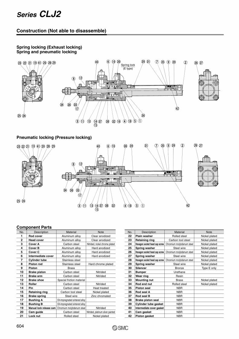
Component PartsNo.123456789101112131415161718192021
DescriptionRod coverHead coverCover ACover BCover CIntermediate coverCylinder tubePiston rodPiston Brake pistonBrake armBrake shoeRollerPinRetaining ringBrake springBushing ABushing BManual lock release camCam guideLock nut
MaterialAluminum alloyAluminum alloyCarbon steel
Aluminum alloyAluminum alloyAluminum alloyStainless steelStainless steel
BrassCarbon steelCarbon steel
Special friction materialCarbon steelCarbon steel
Carbon tool steelSteel wire
Oil-impregnated sintered alloyOil-impregnated sintered alloyChromium molybdenum steel
Carbon steelRolled steel
NoteClear anodizedClear anodized
Nitrided, nickel chrome platedHard anodizedHard anodizedHard anodized
Hard chrome plated
NitridedNitrided
NitridedHeat treatedNickel plated
Zinc chromated
NitridedNitrided, platinum silver painted
Nickel plated
No.222324252627282930313233343536373839404142
DescriptionPlain washerRetaining ringHexagon socket head cap screwSpring washerHexagon socket head cap screwSpring washerHexagon socket head cap screwSpring washerSilencerBumperWear ringMounting nutRod end nutPiston sealRod seal ARod seal BBrake piston sealCylinder tube gasketIntermediate cover gasketCam gasketPiston gasket
MaterialRolled steel
Carbon tool steelChromium molybdenum steel
Steel wireChromium molybdenum steel
Steel wireChromium molybdenum steel
Steel wireBronze
UrethaneResinBrass
Rolled steelNBRNBRNBRNBRNBRNBRNBRNBR
NoteNickel platedNickel platedNickel platedNickel platedNickel platedNickel platedNickel platedNickel platedType E only
Nickel platedNickel plated
Pneumatic locking (Pressure locking)
Construction (Not able to disassemble)
Spring locking (Exhaust locking)Spring and pneumatic locking
Spring lock(E type)
604
Series CLJ2
P0595-P0668-E.qxd 08.11.17 2:57 PM Page 604

ø
ø
ø
ø
ø
ø
18.3 0–0.3
18.3
0
–0.3
18.3
0
–0.3
18.3 0–0.3
M5 x 0.8 unlocking portUnlocked when pressurized
Manual unlocking cam
M5 x 0.8 pressurized locking portPneumatic locking and spring
and pneumatic locking
Silencer
Spring lock
M5 x 0.8Rod side cylinder port
M5 x 0.8Head side cylinder port
Lock nut
111 + Stroke150 + Stroke
Piping port M5 x 0.8
Head cover portin axial direction (R)
M5 x 0.8 unlocking portUnlocked when pressurized
Manual unlocking cam
Lock nut
Width acrossflats 10
Width acrossflats 10
Mounting hole
M5 x 0.8Rod side cylinder port
M5 x 0.8Pressurized locking portPneumatic locking and spring
and pneumatic locking
Silencer
Spring lock
Piping port M5 x 0.8
Head cover portin axial direction (R)
M5 x 0.8Head side cylinder port
111 + Stroke150 + Stroke
M14 x 1.0
M6 x 1.0
M6 x 1.0
2 x ø5.5
M14 x 1.0
Basic Style (B)
CLJ2B16- -EDP
Axial Foot Style (L)
CLJ2L16- -EDP
605
Series CLJ2Fine Lock CylinderDouble Acting, Single Rod
CLJ2
CLM2
CLG1
CL1
MLGC
CNG
MNB
CNA
CNS
CLS
CLQ
RLQ
MLU
MLGP
ML1C
Individual-X�
D-�
-X�
P0595-P0668-E.qxd 08.11.17 2:57 PM Page 605

ø8
ø
øø
ø
ø
ø
ø18.3 0
–0.3
18.3
0
–0.3
18.3 0–0.3
18.3
0
–0.3
Silencer
Spring lockPiping port M5 x 0.8
Head cover portin axial direction (R)
Manual unlocking cam
Lock nut
Mounting hole
Width across flats 10
M5 x 0.8 unlocking portUnlocked when pressurized
111 + Stroke150 + Stroke
M5 x 0.8 pressurized locking portPneumatic locking and spring
and pneumatic locking
Rod side cylinder port
Head side cylinder port
M5 x 0.8 unlocking portUnlocked when pressurized
Width across flats 10
111 + Stroke160 + Stroke168 + Stroke
Lock nut
Manual unlocking cam
Silencer
Spring lock
Rod side cylinder port
Head side cylinder port
M5 x 0.8 pressurized locking portPneumatic locking and spring
and pneumatic locking
Clevis pinM5 x 0.8
M5 x 0.8
M5 x 0.8
M5 x 0.8
M14 x 1.0
M14 x 1.0
M6 x 1.0
M6 x 1.0
2 x ø5.5
Rod Side Flange Style (F)
CLJ2F16- -EDP
Double Clevis Style (D) ∗ Clevis pin and retaining ring are shipped together.
CLJ2D16- -EDP
606
Series CLJ2
P0595-P0668-E.qxd 08.11.17 2:57 PM Page 606

Material: Rolled steel
Single Knuckle Joint: I-LJ016B Double Knuckle Joint: Y-LJ016B∗ Knuckle pin and retaining ring are shipped together.
T-bracket: CJ-T016B
Clevis Pin: CD-Z015 Knuckle Pin: IY-J015A
Material: Stainless steel Material: Stainless steel
Material: Rolled steel Material: Rolled steel
Rod End Nut: NT-015A
Mounting Nut: SNLJ-016B
Material: Brass
ø ø
ø ø ø ø
ø
Part no.
CJ-T016BBore size (mm)
16TC5.5
TDH10
5
TH35
TK20
TN6.4
TT2.3
TU14
TV48
TW28
TX38
TY16
TZ10+0.048
0
Material: Rolled steel
∗ Retaining rings are shipped together. ∗ Retaining rings are shipped together.
TZ
∗ T-bracket includes a T-bracket base, single knuckle joint, hexagon socket head cap screw and spring washer.
Accessory Bracket Dimensions
Double clevis cylinder
607
Series CLJ2Fine Lock CylinderDouble Acting, Single Rod
M14 x 1.0
M6 x 1.0
M6 x 1.0M6 x 1.0
4 x øTC
CLJ2
CLM2
CLG1
CL1
MLGC
CNG
MNB
CNA
CNS
CLS
CLQ
RLQ
MLU
MLGP
ML1C
Individual-X�
D-�
-X�
P0595-P0668-E.qxd 08.11.17 2:57 PM Page 607

B38.2A
16
22A
17
B22A
17
36.7
16
BA
29A
16
B
B
16
BA 26
SMC
SMC
SMC
SMC
Auto Switch Auto Switch
SM
C
SM
C
SM
C
SM
C
(24.5)
Hs Hs
Auto SwitchAuto SwitchHs
Hs
Hs
Auto Switch
Auto SwitchHs
Auto Switch Proper Mounting Position (Detection at Stroke End) and Its Mounting Height
Auto Switch Proper Mounting Position (Detection at Stroke End) and Its Mounting Height
D-A9�
D-C7�/C80
D-C73C�/C80C
D-H7�D-H7�WD-H7BALD-H7NF
D-H7C
( ): For D-A93
D-M9�D-M9�W
Reed auto switch <Band Mounting>
Solid state auto switch<Band Mounting>
Auto Switch Proper Mounting PositionAutto switch
model
Bore size(mm)
16A3
B3
D-C7�D-C80D-C73CD-C80C
A6.5
B6.5
D-M9�D-M9�W
A2.5
B2.5
D-A9�
Auto Switch Mounting HeightAutto switch
model
Bore size(mm)
16Hs20
D-A9�D-M9�D-M9�W
Hs20.5
D-C7�/C80D-H7�/H7�WD-H7NFD-H7BAL
Hs23
D-C73CD-C80C
Hs23.5
D-H7C
Note) Adjust the auto switch after confirming the operating conditions in the actual setting.
~= ~=
~= ~=
~= ~=
(mm)
(mm)
608
Series CLJ2
P0595-P0668-E.qxd 08.11.17 2:57 PM Page 608

Minimum Auto Switch Mounting Stroke
Auto Switch Mounting Bracket: Part No.
Operating Range
D-H7�D-H7�WD-H7BALD-H7NF
D-C7�D-C80
D-C73CD-C80CD-H7C
D-A9�D-M9�D-M9�W
Auto switch mounting
Auto switch model 1
2
Different surfaces
n (n: No. of auto switches)
No. of auto switches mounted
10 15
10 15
10 15
10 15
Same surface
45 + 15(n - 2)
50 + 20 (n - 2)
60 + 22.5 (n - 2)
50 + 27.5 (n - 2)
Band mounting
Different surfaces
Auto switch modelBore size (mm)
167
3
7
4
9
D-C7�/C80D-C73C/C80C
D-H7�/H7�W/H7BAL/H7NFD-H7C
D-A9�D-M9�D-M9�W
[Mounting screw set made of stainless steel]The following set of mounting screws made of stainless steel is available. Use it in accordance with the operating environment. (Please order the auto switch mounting bracket separately, since it is not included.) BBA4: For D-C7/C8/H7 typesNote 2) Refer to page 1814 for the details of BBA4.D-H7BAL auto switch is set on the cylinder with the stainless steel screws above when shipped. When an auto switch is shipped independently, BBA4 is attached.
Auto switch modelBore size (mm)
D-C7�/C80D-C73C/C80CD-H7�D-H7�WD-H7BALD-H7NF
D-A9�D-M9�D-M9�W
ø16
BJ2-016
(1)q BJ2-016w BJ3-1
Note 1) Two kinds of auto switch mounting brackets are used as a set.
Note 1) The following table is applicable for cylinders with two D-A93/M9�/M9�W auto switches. Note 2) For Series CDLJ2, 65 strokes cannot be manufactured, as a reference.
15 + 35
(n = 2, 4, 6···)
(n - 2)2
15 + 40
(n = 2, 4, 6···)
(n - 2)2
15 + 45
(n = 2, 4, 6···)
(n - 2)2
15 + 50
(n = 2, 4, 6···)
(n - 2)2
Same surface
45
50
60
65
1. Auto Switch Mounting Bracket
D-A93
D-M9�D-M9�W
Auto switch model
With 2 auto switches
Different surfaces
—
Less than 20 strokes
Same surface
Less than 50 strokes
Less than 55 strokes
The auto switch is mounted by slightly displacing it in a direction (cylinder tube circumferential exterior) so that the auto switch and lead wire do not interfere with each other.
The proper auto switch mounting position is 5.5 mm inward from the switch holder edge.
(1) (1)
(2)
B-5.5
A-5.5
5.5
5.5
B
A15
Auto SwitchD-M9�D-M9�W
: Parts attached to 2 BJ3-1.
Switch bracket (Stainless steel)
Switch spacer (Stainless steel)
Auto Switch
Set screw (Not used)
Switch holder (Resin)
Auto switch mounting screw
∗ Since the operating range is provided as a guideline including hysteresis, it cannot be guaranteed (assuming approximately ±30% dispersion). It may vary substantially depending on an ambient environment.
609
Series CLJ2Fine Lock CylinderDouble Acting, Single Rod
(mm)(mm)
CLJ2
CLM2
CLG1
CL1
MLGC
CNG
MNB
CNA
CNS
CLS
CLQ
RLQ
MLU
MLGP
ML1C
Individual-X�
D-�
-X�
P0595-P0668-E.qxd 08.11.17 2:57 PM Page 609

∗ For solid state auto switches, auto switches with a pre-wired connector are also available. Refer to pages 1784 and 1785 for details.∗ Normally closed (NC = b contact) solid state auto switches (D-F9G/F9H types) are also available. Refer to page 1746 for details.
Auto switch type Part no. FeaturesElectrical entry (Fetching direction)
D-C73, C76
D-C80
D-H7A1, H7A2, H7B
D-H7NW, H7PW, H7BW
—
Without indicator light
—
Diagnostic indication (2-color indication)
Grommet (In-line)
Besides the models listed in How to Order, the following auto switches are applicable. Refer to pages 1719 to 1827 for the detailed specifications.
Reed
Solid state
610
Series CLJ2
P0595-P0668-E.qxd 08.11.17 2:57 PM Page 610