motor control centers - ge industrialapps.geindustrial.com/publibrary/checkout/det-291?tnr... ·...
TRANSCRIPT

Evolution Series E9000™
Motor Control Centers
Application Guide
GEIndustrial Solutions

Evolution Series E9000* Motor Control CentersGeneral
Section A: GeneralProduct Design & Features ............................................................................................1Bus Features ........................................................................................................................2Unit Features ....................................................................................................................3-5IP20 and Incidental Contact Barrier Features ......................................................6Wire, Cable, and Nameplates ......................................................................................6NEMA Class of Diagrams and Wiring ........................................................................7Codes and Standards........................................................................................................8Short Circuit Considerations..........................................................................................9Fuse Classification ..........................................................................................................10Environmental Considerations ..................................................................................10
Section B: StructureEnclosure Types ..................................................................................................................1Indoor Enclosures........................................................................................................2-13Outdoor Enclosures ........................................................................................................14Enclosure Options ....................................................................................................15-16Bus Selection ......................................................................................................................17
Section C: Mains, Feeders, Incoming LinesMains- General ....................................................................................................................1Fused Switch Mains ..........................................................................................................1Circuit Breaker Mains ........................................................................................................2Arc Flash Mitigation (AFM) Main and Feeder Units..............................................3Feeders-General..................................................................................................................4Fused Switch Feeders ......................................................................................................4AFM Fused Switch Feeders ............................................................................................4Circuit Breaker Feeders....................................................................................................5AFM Circuit Breaker Feeders ........................................................................................5Accessories for Mains & Feeders ................................................................................5Options for Mains & Feeders ........................................................................................6Incoming Line Terminations ..........................................................................................7Automatic Transfer Switches ........................................................................................8Transitions..............................................................................................................................8
Section D: StartersGeneral ....................................................................................................................................1Arc Flash Mitigation (AFM) Starter Units ..................................................................2Circuit Breaker Type Selection Tables ..................................................................3-6Fused Switch Type Selection Tables ..................................................................7-10Starter Options ..........................................................................................................11-12Product Information ................................................................................................13-15
Section E: Miscellaneous UnitsOperator and Metering Panels ....................................................................................1Mounting Plates ..............................................................................................................2-3Lighting and Distribution Panels..................................................................................4Distribution Transformers ..........................................................................................5-6Power Factor Correction Capacitors ....................................................................7-8
Section F: Intelligent MCCGeneral ....................................................................................................................................1Intelligent MCC Configurations ....................................................................................2Programmable Logic Controllers............................................................................3-7Programmable Automation Controllers ..........................................................8-11Example PLC Connections ..........................................................................................12Distributed I/O & Remote I/O ..............................................................................13-16Human Machine Interface (HMI)........................................................................17-18envisage- Energy Management System ..............................................................19
Section G: Solid-State Drives & StartersAdjustable Frequency AC Drives ................................................................................1Adjustable Speed Drives - General ............................................................................2Adjustable Speed Drives - Specifications............................................................3-5Adjustable Speed Drives - Space Height & Assembly ..................................6-7Six Pulse VFD Generic Block Diagram ......................................................................7Adjustable Speed Drives - Configurations ..............................................................8Adjustable Speed Drives - Harmonic Filters ..........................................................9Adjustable Speed Drives - Motor Application Data..........................................10How to Select Drives................................................................................................10-11Solid-State Starters - ASTAT XT ..........................................................................12-16Solid-State Starters - ASTAT BP ..........................................................................17-19Solid-State Starters - Selection Tables............................................................20-27Solid-State Starters - Nonreversing with Primary Disconnect ..................28Arc Flash Mitigation (AFM) Solid State Drives & Starters................................29
Section H: ComponentsSpectra RMS* Mag-Break* Motor Circuit Protectors ....................................1-2Spectra RMS Molded Case Switches..........................................................................3Heavy Duty Fusible Disconnects ................................................................................4New Generation High Pressure Contact (HPC) Switches ................................5Power Break II Insulated Case Circuit Breakers ..................................................6Spectra RMS Circuit Breakers ..................................................................................7-8Ground Fault Current Detection Systems - Model BGFL..................................9Ground Fault Current Detection Systems - Model GFM ................................10C2000 Line Motor Starters ..........................................................................................11300-Line Motor Starters ........................................................................................12-13Overload Relays................................................................................................................14Industrial Relays ..............................................................................................................15Accessories for C2000 Contactor and Control Relay......................................15CR104P Pilot Devices......................................................................................................16C2000 Pilot Devices ........................................................................................................17Solid-State Motor Winding Heater ..........................................................................18EPM 6000 Power Meter ................................................................................................19EPM 6010 Automation Power Meter ......................................................................20EPM 7000 Power Meter ................................................................................................21PQM II Power Quality Meter ........................................................................................22Three-Phase Voltage Monitors - Model SPVRB..................................................23High-Resistance Ground ..............................................................................................24MM200 Motor Management System ..............................................................25-27MM300 Motor Management System ..............................................................28-30Integrated Tranquell* HE & ME - Surge Protective Device (SPD) ............31-32
Section J: Application DataApproximate Motor Full-Load Current Ratings ....................................................1Mag-Break Magnetic Circuit Breaker Trip Set Positions ..................................2Thermal-Magnetic Trip Ratings for Motor Circuits..............................................3Overload Heater Tables for Ther-Mag Controllers..............................................4Overload Heater Tables for Mag-Break Controllers ......................................5-9Overload Heater Tables for Overload Relays ....................................................10Overload Heater Tables for Fused Controllers............................................11-12Starter Fuse Selection ............................................................................................13-14Control Transformer Fusing ........................................................................................15Heat Loss Considerations ............................................................................................15Motor Load ..........................................................................................................................16Non-Motor Loads......................................................................................................16-19Publication References ..........................................................................................20-21Electrical Data ............................................................................................................22-23
Section K: Drawings & TestingE9000 MCC Unit Numbering System ....................................................................1-3Special Paint..........................................................................................................................4Packing & Storing................................................................................................................4Standard Commercial Tests & Inspection ..........................................................5-6
Section L: Typical CircuitsFVNR Size 1-4 ..................................................................................................................1-2FVNR Size 5-6 ..................................................................................................................3-4FVNR with Voltage Indicator Module ........................................................................5FVR Size 1-4 ..........................................................................................................................6RVAT Size 2-6 ........................................................................................................................72S2W-C.T., V.T., C.H. Size 1-4 ......................................................................................8-92S2W with MM200 ..........................................................................................................102S-PW Size 1-5 ..................................................................................................................11Wye-Delta Open Transition ................................................................................12-13Distribution Transformers ............................................................................................14Single-Phase Panelboard ............................................................................................15Three-Phase Panelboard..............................................................................................16FVNR with PLC....................................................................................................................17RVNR-AT with PLC ............................................................................................................182S2W with PLC ..................................................................................................................19ASTAT XT ..............................................................................................................................20ASTAT XT Bypass ..............................................................................................................21ASTAT XT Isolation Bypass ..........................................................................................22ASTAT XT Bypass Emergency Bypass ....................................................................23ASTAT XT Isolation Bypass Emergency Bypass ................................................24ASTAT BP ..............................................................................................................................25ASTAT BP Isolation............................................................................................................26Adjustable Speed Drives ..............................................................................................27High-Resistance Ground ..............................................................................................28MM200 ..................................................................................................................................29MM300 ..................................................................................................................................30
Section M: SpecificationsMCC 600 Volts & Below................................................................................................1-3
DET291F_Section_A:Layout 1 7/7/15 1:02 PM Page 1

Evolution Series E9000* Motor Control Centers
Evolution Series E9000: Safety and Flexibility are StandardGE’s Evolution Series E9000 Motor Control Centers (MCC) provide safe and flexible centralizing of motor starters andrelated control equipment. It combines motor control units,feeder units, distribution transformers, lighting panels, relays,remote and local control, sophisticated communications,metering and other miscellaneous devices to be containedin a single floor-mounted structural assembly fed from acommon enclosed main bus.
Rugged and ReliableGE motor control centers are constructed of standardizedheavy gauge vertical sections housing vertical and horizontalbuses, wiring channels and compartmented control units.Shipping splits are bolted together to form a single line-upassembly. Units are mounted and wired in accordance withthe wiring class specified. The motor control center may bepowered by incoming line connection at a single point protectedby an upstream disconnect or provided with a main protectivedevice within the equipment. Where possible, motor controlcenters bear UL section and unit labels.
E9000 with AFM: Even More ProtectionGE’s E9000 MCC with Arc Flash Mitigation (AFM) units is anew offering for customers and specific applications whereadditional protection of personnel is essential. The AFM unitswere designed around lowering the potential for electricalshock hazards in motor control centers.
The AFM unit design includes optional IP20 devices and incidentalcontact safety barriers in an effort to prevent accidentalcontact with energized parts during maintenance.
New Level of Arc Flash MitigationThe E9000 AFM units are designed to reduce the likelihood ofexposure to electrical shock and the potential of internal arcing faults from occuring during maintenance. The retractablestab mechanism allows for closed-door racking of the unit,providing added protection to the electrical personnel fromthe dangers of an arc flash occurrence.
The introduction of a compact NEMA contactor in these AFMunits will allow a minimum of IP10 protection with optionalIP20 terminal protection for starters using this contactor.Other IP20 protection options are available in starter unitsincluding IP20 control power transformer fuses and pilot devices.
E9000 MCC with Arc Flash Mitigation UnitsE9000 MCC

Evolution Series E9000* Motor Control CentersGeneral
A
A1
Product Design and Features
Design flexibility, performance, personnel and equipmentpro tection, ease of maintenance and installation are all con-tained in the Evolution Series E9000*. Evolution Series E9000features, such as separate wiring troughs, split-type terminalboards, isolated bus, drawout starter units, operating mech-anisms, and provisions for starter interchangeability, are designed for a high level of reliability, safety and convenience.The new Arc Flash Mitigation (AFM) units were added in order toprovide additional safety features and flexibility for customers.
Enclosure FeaturesThese steel-enclosed control centers can be joined togetherto centralize, protect and control the most complex systemsof industrial auxiliary drives, or the simplest of loads such asfan or pump controls. As the need arises, additional sectionscan be added to an existing lineup in the field, often timeswithout the need for a transition section.
A paint finish is applied to all un-plated steel parts. The powdercoating process passes 600 Hr. ASTM117B salt spray tests andprovides lasting protection.
All case side wireways are roll-formed to provide a 1/2" lip for crosswiring to rest on, thus preventing skinned insulation.
Easily removable plastic knock-outs are provided in the verticalwireway ladder assembly to allow routing of field wiring into units.
An incoming-line terminal compartment can be located at the top orbottom of a vertical section to allow cable termination with minimumbending. The standard 600-ampere incoming line terminal compartment shown is furnished with mechanical type lugs. Other incoming lineterminal compartments are available for main bus ampacities upto 2500 amperes.
An optional snap-in steel barrier in the wireway provides added isolation for low voltage signal wiring between units.

Evolution Series E9000* Motor Control CentersGeneral
A2
ABus Features
Splicing
E9000 MCC can be spliced onto existing 7700 Line, 8000 Line andSpectra MCC for 1200A (supplied with 2" bars) and below without atransition section. Horizontal bus location in E9000 matches the existing bus location. Main bus amperage 1200A and greater with 4" bus bars can be spliced together but requires a transition section.
Main Bus Barrier
Clear Lexan barriers located in front of the main horizontal bus isolatethe bus from the top horizontal wireway. Maintenance personnelcan easily gain entrance to the top horizontal wireway of the controlcenter without danger of contact with a live bus.
Infrared Scanning
Windows on the main bus are available when required. Please contact the factory for further information.
Vertical Ground Bus and Unit Ground Stab
(Optional) Vertical copper ground bus allows direct grounding ofunit saddles to the equipment ground bus. A unit ground bus stabengages the vertical ground bus before the unit power stabs engage the vertical bus. A load ground lug is available for customercable grounding. Termination points are located at the rear of thebucket, next to starter.
Insulated and Isolated Vertical Bus
A polyester-reinforced “sandwich” insulates and isolates the verticalbus and helps prevent the spread of faults from starter and feederunits to vertical or horizontal bus. Small stab openings provide accessto vertical bus and maintains effective isolation. 65kA short circuitbracing is standard for Evolution Series E9000 MCC.
Vertical Bus Shutters
(Optional) For standard E9000 MCC’s, a vertical bus shutter mecha-nism can be supplied which covers the vertical bus stab area whena plug-in starter or feeder is withdrawn. Cap plugs are standard toclose unused stab openings.
(Standard for AFM) For E9000 AFM, a vertical bus shutter mechanismis supplied as standard. The shutter will be mechanically closedwhen the stabs are retracted, isolating the bus and preventing contact. When the stab is extended and engaged with the bus, theshutter will reverse the operation.
The vertical bus shutter for AFM design is different than the stan-dard E9000 vertical bus shutter option. The AFM shutter and shutterguide are shown above.

Evolution Series E9000* Motor Control CentersGeneral
A
A3
Unit Features
Doors
New doors mounted on the case feature a removable hinge pinproviding easy door removal and accurate alignment.
AFM doors have a visual stab and shutter indicator feature as well as a remote racking provision.
New oversized laser-engraved unit nameplates on 12" units andlarger feature 1 to 9 lines of up to 20 characters 0.18" high or 4lines of up to 10 characters 0.30" high. Nameplates use Microsoft®
Windows® Arial font. Custom non-English characters are an option.
Device bracket mounts 30mm for compact pilot devices andbracket swings open to allow easy access to unit components,wiring and terminal blocks. Fully insulated – does not requiregrounding.
Stationary Stabs
Combination starter and feeder units of plug-in construction utilize a positive guidance system. Plug-in stabs are rated 250A and 600A. The 250A stab connections shown are made with copper unit power stabs which are under double spring pressureand engage the vertical bus to provide positive contact.
Retractable Stabs
Extended Stabs
Retracted Stabs
AFM unit stabs are retractable while maintaining a closed-doorunit. They move in a horizontal motion to engage and disengagefrom the bus when retracted (below) or extended (above).
The 600A stab shown uses a two-step engagement with verticalbus for low insertion/withdrawal force. Line side cables crimped directly into spring reinforced tin-plated copper stabs. No hiddenline side cable in rear of units. Tapered glass polyester stab mounting base gives positive plug-in alignment with vertical bus.

Evolution Series E9000 Motor Control CentersGeneral
A4
AUnit Features (continued)
Safety Interlocks
An interlock release system is provided so that – if it becomes necessary for maintenance purposes – the disconnect may beclosed with the door open. A by-pass is provided to allow openingthe door with the disconnect closed.
Note: Only qualified personnel familiar with the equipment should use the interlock release and by-pass features.
AFM units utilize a mechanical stab interlock on the top of the unit to prevent inserting the unit into the enclosure while the unit stabs are extended.
Padlocks
Units can be withdrawn to a disconnected position and padlocked for maintenance.The vertically mounted integral handle can be locked in the OFF position. A drilling pattern is furnished, allowing the handle to be modified for locking in the ON position with a single padlock. This modification should only be made afterthe user determines it is desirable to lock the disconnect in the ONposition. Padlock to have maximum 3/8" shackle.
Disconnects
Lift up handle design to allow full access to fuses and CB rating plug. Position indication ON-TRIP-OFF.
Horizontal handles are standard on 6" 150A and 12" 250A feederbreakers to optimize space. Optional vertical handles are available,but will increase the unit height. Horizontal handles are not avail-able with AFM units.

Evolution Series E9000 Motor Control CentersGeneral
A
A5
Unit Features (continued)
Interchangeable Units
Unit Features
For flexibility, many units can be interchanged. This design allows quick, easy field changes when modifications are desiredafter installation. Front accessible quarter-turn latches provide for ease of securing and withdrawal of all plug-in units.
AFM Retrofit Kit Unit Shelves
With the AFM unit, a different unit shelf is required to support themovement of the unit while it is being racked in or racked out.When retrofitting an existing E9000 MCC, a Retrofit Kit will need tobe ordered with the AFM Retrofit bucket. The Retrofit Kit will includethis AFM shelf.
AFM units can be ordered to retrofit existing E9000 MCC by ordering the AFM Retrofit Kit along with the unit.
High density two-piece, pull-apart control terminal boards featureup to 18 points in 12” high units. External and internal unit connections are made on opposite sides, allowing the unit to bewithdrawn without disconnecting control wiring. Accommodatesup to (2) #12 AWG wires with ring, fork or bare terminations. Rated 30 Amps, 600 Vac. Meets NEC Article 430.74.
(Optional) Motor power terminal blocks can be supplied in Size 1 & 2 to allow disconnecting motor wires when removing a unit.NEMA Type BT wiring.
The E9000 MCC unit is equipped with the CR305 contactor as standard configuration. The C2000 contactor is available for many configurations to obtain a compact footprint.
The E9000 AFM unit is equipped with the C2000 contactor as standard configuration. The CR305 contactor is available for most configurations. Please contact factory if the CR305 contactor is required in an AFM unit.

Evolution Series E9000* Motor Control CentersGeneral
A6
AIP20 and Incidental Contact Barrier Features
(Optional) IP20 rated fuses are available. Please contact factory.
(Optional) CR104P Lights and Push butons are available with optional IP20 accessory. Please contact factory.
(Optional) C2000 Contactor is available with optional IP20 accessory. Please contact factory.
(Optional) Clear Lexan incidental contact barriers are available for CR305 contactor.
Wire and CableStandard control and power wire includes flame-retardant,(VW-1) moisture-heat-and oil-resistant thermoplastic insulation rated 600 volts, with stranded copper conductors,types MTW and THW.
Standard colors� are:Red – AC ControlBlue – DC ControlBlack – AC/DC Power and CPT primaryGreen – GroundWhite – Neutral
Optional wiring available includes SIS heat-resistant syntheticrubber-covered switchboard wire and XHHW flame-retardantcross-linked synthetic polymer, both rated 600 volts withstranded copper conductors, and a VW-1 flame rating (no PVC).
� Note: Not all colors are available with optional wiring.
NameplatesUnit service designation nameplates are furnished whenspecified. Nameplates can be supplied as blanks suitable forfield engraving, or engraved at the factory.
The standard unit service designation nameplate is of 2-ply thermoplastic material, black face with white core, 2 5/32" x 3 1/2", or 1" x 3" depending on the unit configuration,fastened with non-corrosive nylon clips. Stainless steel screwsare available as an option.
Nameplates are engraved with white letters on a blackbackground.

Evolution Series E9000* Motor Control CentersGeneral
A
A7
Wiring Features by NEMA Classification Class I Class IS Class II Class IIS Type of Power or Control Termination Furnished A B C A B C B C B C Pull-apart and numbered control terminal boards on unit starter–Sizes 1, 2, 3 and 4 No Yes Yes No Yes Yes Yes Yes Yes Yes Stationary and numbered control terminal boards on unit starter – Sizes 5, 6 and 7 No Yes Yes No Yes Yes Yes Yes Yes Yes Pull-apart and numbered power terminal boards on unit starter –Sizes 1 and 2.
(On Type A wiring: Same type of numbered terminals on starter itself for Sizes 1, 2, 3 and 4) No Yes Yes No Yes Yes Yes Yes Yes Yes Numbered terminals on starter itself for power connection with no power terminal boards – Sizes, 5, 6 and 7 Yes Yes Yes Yes Yes Yes Yes Yes Yes Yes Stationary master terminal boards (Top, bottom or rear of section)
For control – Sizes 1 thru 5 / For power – Sizes 1 thru 3 (E9000 Sizes 1 and 2 only) No No Yes No No Yes No Yes No Yes Unit terminal boards for feeder tap units and distribution panels No No No No No No No No No No Starter-unit-mounted pilot devices internally wired to starter – Sizes 1 thru 7 Yes Yes Yes Yes Yes Yes Yes Yes Yes Yes Terminal board points for remote devices (Excluding extra tie points) No Yes Yes No Yes Yes Yes Yes Yes Yes Master terminal-board wiring connections No No Yes No No Yes No Yes No Yes Factory-wired interconnections between units in the same motor control center No No No No No No Yes Yes Yes Yes
Type of Drawings Furnished Outline and summary sheet (Schedule of units) Yes Yes Yes Yes Yes Yes Yes Yes Yes Yes Unit elementary wiring diagrams showing numbered terminal points (Terminal boards
not furnished on Type A) Yes Yes Yes Yes Yes Yes Yes Yes Yes Yes Unit elementary wiring diagrams showing numbered terminal points and interconnections
to other units and/or to the first level of remote devices No No No No No No Yes Yes Yes Yes Schedule of wires to master terminal blocks No No Yes No No Yes No Yes No Yes Custom drawings as specified by user No No No Yes Yes Yes No No Yes Yes
A computerized manufacturing process necessitates that the E9000 Line motor control center standard unit numbering system be followed to identify the section and location ofeach unit. This is explained in detail in application data (Section J). It greatly simplifies wire tracing of interconnection wires, and is beneficial to the application of programmablecontrol. The Outline and Summary drawing furnished with the equipment cross references the unit numbers and customer unit designations when specified.
NEMA Class of Diagrams and WiringMotor control centers are classified by NEMA asfollows:
NEMA Class I Definition�
Class I motor control centers consist essentially of a mechanicalgrouping of combination motor control units, feeder tapunits and/or other units arranged in a convenient assemblyand connect to the horizontal and vertical common powerbus to the units.
This class does not include interwiring or interlocking betweenunits or to remotely mounted devices, nor does it includecontrol system engineering. Diagrams of the individual unitsonly are supplied.
NEMA Class II Definition�
Class II motor control centers consist of a grouping of combination motor control units, feeder tap units and/orother units designed to form a complete control system.They include the necessary electrical interlocking and inter-wiring between units and interlocking provisions to remotelymounted devices in addition to the connections from thehorizontal and vertical common power bus to the units.
The control manufacturer shall provide a suitable diagramto illustrate operation of the control associated with themotor control center.
NEMA Class IS and IIS Definition�
Class IS and IIS motor control centers shall be the same asClass I and II motor control centers except custom drawingsshall be provided in lieu of standard drawings.
� From NEMA Standard 18-2001.
Examples of custom drawings are:• Special identifications for electrical devices• Special terminal numbering designations• Special sizes of drawings
The drawings supplied by the manufacturer shall convey thesame information as drawings provided with Class I and IImotor control centers, additionally modified as specified bythe user.
When to Specify Class ISpecify NEMA Class I control centers for independently operatedmotors requiring no interlocking or other interconnectionbetween units.
When to Specify Class IIWhen factory interconnections are desired to provide suchfunctions as sequencing and other interlocking or intercon-nection, the control centers required are NEMA Class II.
When to Specify Class IS and IISWhen custom drawings are desired to show special deviceidentification, special terminal numbering, or special diagramsize, etc. the control centers required are Class IS or IIS.
Wiring TypeThe NEMA classes are sub-divided into A, B and C depending on the type wiring furnished, with type B further having typeB-D for customer load wiring direct to the device and B-T forcustomer wiring to a load TB (size 1 and 2 starters).
Note: For feeders and large starters, customer must wire direct to unit device terminals.
Note: In addition to NEMA prescribed wiring types, GE offers a NEMA 1A Modified MCC.This type of MCC will be supplied without wiring and without control diagrams. GE canmount low voltage control devices on the pilot device bracket and supply terminalboards. This would be considered on OEM product.

Evolution Series E9000* Motor Control CentersGeneral
A8
A Codes and Standards
Motor control centers are manufactured to NEMA standard ICS 18and are eligible to receive the Underwriters Laboratories listing markunder standard UL 845. Vertical sections and units which have beenlisted with UL will bear the UL/cUL listing mark (see right for exam-ples). Since vertical sections and units are listed independently, it ispossible to have combinations of listed and non-listed sections andunits within the same control center. Sections and units which willbe shipped with the UL listing mark are identified in the appropriatesections of this publication.
The National Electrical Code (NEC) covers installation of electricconductors and equipment for installations identified in the NEC Article 90. The NEC is not intended as a design specification andacceptance of an installed motor control center by a local code authority relies on factors independent of the equipment asshipped from the factory. In general, equipment which bears theUL listing mark can be installed to meet the NEC. Compliance toNEC is the responsibility of the installer. Where 100 percent ULlisted equipment is mandatory or there are other special code requirements refer to the factory for verification.
The NEC defines several types of control circuits and the over-currentprotection required for each type. The following paragraphs providea general reference to the NEC Article applicable for the more common control circuits.
NEC Articles 430.72(a) and (b) cover motor control circuits tappedfrom the load side of a motor branch-circuit short-circuit protectivedevice (unit disconnect). Control circuit conductors from such atapped control circuit shall be protected in accordance with NECTable 430.72(b), which lists the maximum fuse or circuit breakerrating vs. conductor size.
Motor control circuits other than such tapped control circuits (commoncontrol transformers or external power source) shall be protectedagainst overcurrent in accordance with Section 725.12 or 725.35, asapplicable. This section of NEC also indicates the type power sourceand field wiring conductor sizes.
Where a motor control circuit transformer is provided, the trans-former should be protected in accordance with NEC Article 430.72(c).Transformers other than motor control circuit transformers shouldbe protected in accordance with NEC Article 450.3(b).
Section Label
UL #E33752, Vol. 1, Sec. 5.
Seismic Label

Evolution Series E9000* Motor Control CentersGeneral
A
A9
Short Circuit ConsiderationsAll ratings in this publication are RMS symmetrical amperes
Short-Circuit Current RatingsThe NEMA Motor Control Center Standard ICS 18-2001 definesthe short-circuit rating of a motor control center as follows:
“The motor control center short-circuit rating shall be themaximum available rms symmetrical current in amperespermissible at its line terminals. It shall be computed as thesum of the short-circuit current contributions of the motorsconnected to the motor control center and the maximumavailable current, including all other short-circuit currentcontributions of the supply system at the point of connectionto the motor control center.”
Motor Control Center Bus
Fig. 1
Figure 1 illustrates simply the basis of determining the availableshort-circuit current. The individual short-circuit current ratings of the main bus extensions, combination-controllerunits and feeder-tap units must equal or exceed availableshort-circuit current.
Is is the short-circuit current available from the system at thepoint where the motor control center is connected. Im is theshort-circuit current contribution of the motors connected tothe motor control center. If exact information is lacking, themotor contribution can be estimated at four times (4X) thecontinuous-current rating of the main horizontal bus. Isc isthe available short-circuit current to be used as the basis forselection. Thus: Isc = Is + Im.
High available short-circuit currents of modern distributionsystems require special consideration so that equipmentmay be operated within its rating. The cost and operationalacceptability of the following should be carefully considered:1. Use load-center distribution systems with smaller trans-
formers which limit the available short-circuit current.2. Use a current-limiting busway, reactors or higher-impedance
transformers to reduce the available short-circuit current.3. Use current-limiting fuses, current-limiting breakers, or
breakers with limiters, in all combination starters andfeeders in the control centers.
Main Protective DevicesA motor control center requires adequate overcurrent andshort-circuit protection. This is the function of the main protective device. It may be located in or remote from the
control center and sized per NEC A or 240 for horizontal busprotection. Wherever located, it must have an interruptingrating equal to or greater than the available short-circuitcurrent at the point of its connection to the system. If locatedat the control center, this value would be the system availableshort-circuit current, Is (Fig. 1).
A motor control center should be protected for all types offaults from low-level arcing ground faults to bolted three-phase faults which can develop the full available short-circuitcurrent. Line-to-line and line-to-ground arcing faults (oftenproduced by contaminated atmospheres, foreign materials,etc.) can be appreciably lower in magnitude than the availableshort-circuit current and must be assumed not to be self-extinguishing. Even low-level arching faults are capable ofreleasing tremendous energy at the point of fault and canbe highly destructive.
A Spectra (molded case switch) or a non-automatic insulatedcase circuit breaker must be properly coordinated with upstream protective devices.
For full protection against all levels of arcing faults ongrounded systems, a ground-fault relay is recommended.The ground-fault system is a protective means that respondsto phase-to-ground current, but is not affected by phase-to-phase current. It is used to protect motor control centersfrom extensive damage, which can be caused by phase-to-ground arcing faults.
Fuses are single-pole interrupters. An arcing fault may notnecessarily be cleared by a single-pole interruption, as thefault can be back-fed from the other energized phases. Thisreduces the fault current, increasing the blowing time of theenergized fuses. Because of this delay, severe equipmentdamage may occur. Single-phasing is eliminated with fast-acting three-pole fused interrupter switches which openwhen a single fuse blows.
An electrically operated HPC switch with single-phase detectorwill meet the three-phase disconnection (single-phase protection) recommendations for a main protective device.
When switches without a three-phase trip are used, an ITIBGFL ground-fault protection scheme is particularly recom-mended since damaging arcing faults almost always involveground. It should operate the trip device on the closest line-side three-phase disconnect.
Main Horizontal Bus and Vertical Bus ExtensionsThe standard bus short-circuit withstand rating is 65 kAIC symmetrical amperes. Also available as an option is 100kAIC.The bus rating must equal or exceed the available short-circuit current. Refer to Structure (Section B) for ratings.

Evolution Series E9000* Motor Control CentersGeneral
A10
ACombination Motor Control UnitsThe short-circuit rating of a combination controller is basedon tests with rated short-circuit current available at the lineterminal of the control center and at rated voltage. Theshort-circuit rating must equal or exceed the availableshort-circuit current. Refer to Starters (Section D) for ratings.
Feeder Tap UnitsAll feeder tap units must have a short-circuit rating whichequals or exceeds the available short-circuit current. Referto Feeders (Section C) for ratings.
Fuse Classification
UL classifications are the most definitive method of determiningfuse characteristics, and are used in this publication. Use ULfuse “Class” when specifying type of fuse.
UL classifications used in motor control centers are:
A. Class R – current-limiting type fuses with reject mountingfeatures. Class R fuses are sub-divided into Classes RK-1 andRK-5, depending on maximum peak let-through currents.RK fuses are rated 600 amperes maximum and 250 voltsor 600 volts.
B. Class J-TD – are more current limiting than RKs and due totheir unique dimensions have an inherent rejection feature.Ratings are 600 amperes maximum, 600 volts. (Time delayClass J-TD fuse may limit component damage under fault.)
C. Class L – are current limiting and due to their uniquemounting dimensions have an inherent rejection feature.Ratings are 601 amperes minimum, 600 volts.
Fuses marked with “Time-Delay,” “Dual-Element” or similardesignations are time-delay type fuses and will generallycarry 500 percent rated amperes for 10 seconds, thus allowinga smaller rated fuse to be used in most starter applications.
Fuses that are mechanically interchangeable may not beelectrically equivalent. Refer to the fuse manufacturer for interrupting rating and current-limiting characteristics.
Fuse Classifications
� Check fuse manufacturers for specific fuse characteristics
Environmental Considerations
The standard E9000 motor control center is designed for operation in a clean, indoor environment having a 40°Cmaximum ambient temperature.
The nominal minimum temperature for storage is -40°C andfor operation, -20°C. Motor control center space heaters arerecommended whenever temperature conditions below 0°Cwill exist. Where extreme cold temperatures are to be encoun-tered for long periods of time. It is recommended that themotor control center be installed in heated rooms or enclosures.
For ambient temperatures above 40°C, special considerationmust be given to the need for ventilation, ambient-compensatedbreakers and overload relays, special wire insulation andoversized control transformers. Ambient compensated over-loads provide essentially constant trip setting as the controlambient varies.
For indoor environments subject to falling liquids, NEMA 2dripproof enclosures are recommended. If water spray andsplashing are to be encountered, NEMA 2 construction shouldalso be used. Space heaters may be desirable to preventcondensation on internal parts.
For outdoor installations, NEMA 3R non-walk-in weatherproofenclosures are required. Thermostatically controlled spaceheaters and ambient-compensated breakers and overloadrelays should be considered for these applications. Provisionsfor heating and cooling the entire outdoor enclosure arealso available. Standard NEMA 3R construction is suitable forwind velocities up to 75 mph. Beyond this, up to 130 mph,specially reinforced enclosures are available through Strategic Equipment Packaging Services. This special designis also necessary if the NEMA 3R enclosure has to withstandseismic conditions, including seismic Zone 4 applications.
E9000 motor control center is available for earthquake conditions.It is IBC rated. Please see DET-463.
For dusty atmospheres, see Section B.
The altitude limit for the standard electro-mechanical motorcontrol center design is 6000 feet. Applications above thisshould be referred to the Company for recommendations.Some solid-state components are only rated to 3300 feetand may reduce the altitude limit of the motor control center.
Fungus-proofing of organic materials is inherent. Keeping equip-ment dry and above the dew-point is the best way of avoidingfungus-growth, and the use of space heaters is recommendedfor this purpose. Heaters should be energized if the motor controlcenter is to be stored for any length of time. Where export cratingis involved, provisions must be made on the outside of thecrate for access to space heaters.
Characteristic� UL StandardClass J-TD Class R Class L
Ampere Range 0-600 0-600 601-6000
Voltage Ratings 600 250 600600InterruptingRating RMSSymmetrical Amperes
200K 200K 200K
Current-Limiting Yes Yes YesRejection Type Yes Yes Yes

Evolution Series E9000* Motor Control CentersStructure
B
B1
Enclosure Types
GE motor control centers are made up of standardized verticalsections housing vertical and horizontal bus, wiring channelsand compartmented control units. Sections may be bolted together to form a single panel assembly powered by lineconnection at a single point. Normal shipping split is three sections maximum.
NEMA Type 1 – Gasketed – Semi Dust-tight, IndoorIntended to cushion doors and mitigate vibration. Standardfinish is light-gray ANSI 61 over a phosphate rust inhibitor.All unpainted parts are zinc-chromate electroplated or galvanized. Enclosures are furnished with bolt-on rear covers.Hinged rear doors are available as an option. Pan-typedoors utilize quarter-turn fasteners. Gasketed doors, coverplates, and operating handles are available as an option.Two heavy-duty 3" by 1-1/2", 12-gauge floor sills and 1/4"structural lifting lugs are included. Open bottom is standard.
NEMA Type 2 – Drip-proof, IndoorIntended for use indoors to protect the enclosed equipmentagainst falling noncorrosive liquids and falling dirt. Dripshields
on top of the motor control center and neoprene closed-cellgasketing afford protection from falling and splashing liquids.They are not water-tight. Similar to NEMA 12 gasketed construction except with catch pan-type dripshield on topand with open bottom. Dripshield extends four inches beyondfront of motor control center. Standard finish: light gray ANSI61. Furnished with removable conduit cover plates unlessotherwise specified.
NEMA Type 3R – Rain-proof, OutdoorIntended for use outdoors to protect the enclosed equipmentagainst rain. They are not dust-proof, snow-proof nor sleetproof (ice-proof).
Type 12 – Industrial Use – Dust-tight and Drip-tight, IndoorIntended for use indoors to protect the enclosed equipmentagainst fibers, flyings, lint, dust and dirt, light splashing,seepage, dripping and external condensation of noncorrosiveliquids.
1HGSimilar to NEMA 1 gasketed construction except that bottomplates are furnished and all removable plates are gasketed.

Evolution Series E9000* Motor Control CentersStructure
B2
B
Indoor EnclosuresFront Elevation & Mounting Locations (13", 20", 22" & 25" Deep Sections)
Evolution Series E9000* Motor Control CentersStructure
B
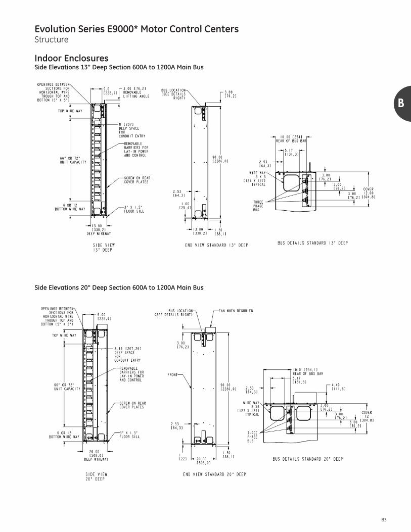
B3
Indoor EnclosuresSide Elevations 13" Deep Section 600A to 1200A Main Bus
Side Elevations 20" Deep Section 600A to 1200A Main Bus

Evolution Series E9000* Motor Control CentersStructure
B4
B
Indoor EnclosuresSide Elevations 25" Deep Back-to-Back Section 1200A Main Bus
Side Elevations 22" Deep Section 1600A to 2500A Main Bus

Evolution Series E9000* Motor Control CentersStructure
B
B5
Indoor EnclosuresSide Elevations 25" Deep Back-to-Back Section 1600A to 2500A Main Bus
Top Conduit Entry (13", 20", 22" & 25" Deep Sections)

Evolution Series E9000* Motor Control CentersStructure
B6
B
Indoor EnclosuresBottom Conduit Entry 13" Deep Section
Bottom Conduit Entry 20" Deep Section

Evolution Series E9000* Motor Control CentersStructure
B
B7
Indoor EnclosuresBottom Conduit Entry 22" Deep Section
Bottom Conduit Entry 25" Deep Section

Evolution Series E9000* Motor Control CentersStructure
B8
B
Indoor EnclosuresElevation and Mounting 30" Deep Section 600A to 1200A Main Bus
Top Conduit Entry 30" Deep Section

Evolution Series E9000* Motor Control CentersStructure
B
B9
Indoor EnclosuresBottom Conduit Entry 30" Deep Section
Details for Auto Transformer

Evolution Series E9000* Motor Control CentersStructure
B10
B
Indoor EnclosuresDrip Pan — Nema II 13" Deep Section
Drip Pan — Nema II 20", 22", 30" Deep Sections
Drip Pan — Nema II 25" Deep Section Back-to-Back

Evolution Series E9000* Motor Control CentersStructure
B
B11
Indoor EnclosuresType C Master Terminal
Used for L and U Shaped Motor Control CenterArrangements
Back-to-back Configuration with Wrap-Around Corner Section
The wrap-around corner section is standardsections which accommodate plug-in units,therefore no space is lost in the transition.

Evolution Series E9000* Motor Control CentersStructure
B12
B
Indoor EnclosuresIncoming Line Terminations

Evolution Series E9000* Motor Control CentersStructure
B
B13
Indoor Enclosures

Evolution Series E9000* Motor Control CentersStructure
B14
B
Outdoor Enclosures
UL Listed Type 3R Non-Walk-In Enclosure (Standard)The standard NEMA 3R enclosure consists of a specially constructed MCC section with a mating framework whichsupports the roof and extended front. The basic design issimilar to switchboard construction. The smaller footprintwill permit a broader usage than the optional NEMA 3R construction. Meets Seismic Zone 4.
• Three-point door latch• 90° door with wind stop• Reinforced roof• Crane lifting• 2° roof pitch• Shipped via flatbed truck• 3" floor sills

Evolution Series E9000* Motor Control CentersStructure
B
B15
Enclosure Options
Space HeatersSpace heaters are used to prevent moisture condensation onthe inside of the motor control center. One heater (62.5 wattsat 120 volts AC) is installed in the bottom of each verticalsection. UL requires space heaters be controlled by a ther-mostat. One thermostat can control up to 23 heaters and islocated in the top horizontal wireway.
A terminal board for connecting an external 120-volt powersource is standard. The terminal board is located in the top horizontal wireway adjacent to the thermostat(s). This is recommended since it permits the space heaters to be energizedeven when the motor control center itself is deenergized. Ifexport crating is involved, the space heater circuit can bewired to an external plug for energizing the heaters duringshipment and storage.
When specified, space heater power can be provided fromwithin the motor control center. Include the required distributiontransformer with primary and secondary protection in themotor control center.
An enclosed foreign voltage disconnect switch is available asan option.
Bottom PlatesPlates bolt on to the bottom of each motor control centersection. They may be removed to facilitate installing conduit.
Extended Height Pull Box (Top Hat)A pull box can be mounted on top of a vertical section whenspecified. The standard height is 12 inches; 6-, 18-, and 24"heights are also available. Top, front, and end covers are re-movable for access.
Special transitions to 8000 line and low-voltage switchboardsare available upon request. Please consult factory.
Rodent BarriersMetal plates bolted to the bottom of each end section to closethe opening between the front and rear floor sills. Not requiredif the floor sills will be removed or imbedded in concrete.
Extra Width Vertical Wireway24" wide sections can be furnished with 8" wide verticalwireway and door.
Motor Control Center ConstructionMajor Structural Components Side Sheets, L-H & R-H 0.075"Vertical Bus Mounting Channels 0.090"Case Sills, Front/Rear, Top/Bottom (13 Gauge)Top Horizontal Channel
Lifting Channel (Top) 0.187"Channel Sills, Front/Rear 0.105" (12 Gauge)Enclosing Covers/PanelsRear Covers, 13" & 30" Deep 0.075" (14 Gauge)Rear Covers, 20" & 22" Deep 0.060" (16 Gauge)Endplates 0.060" (16 Gauge)Top Conduit Covers 0.060"Bottomplates 0.060"Vertical Wiretrough Door 0.060"
Other SteelUnit Barrier Shelves 0.063"Unit Cover Doors 0.075"Unit Saddles 0.090"

Evolution Series E9000* Motor Control CentersStructure
B16
B
Enclosure Options
Note that bolt down locations for sections with seismic bracingchange from center of structure (left to right), to four cornerswith .635 clearance holes for 1/2" bolts.
Mounting Requirements for Seismic NEMA 3R with Optional Heavy Base
Note:Seismic Zone 4 testing was performed using 1/2"-13 Grade 5 bolts, torqued to 70 foot-pounds, located in each of the four corners in each section.
Estimated shipping weights per section
Center of Gravity
For a uniformly loaded 90" high x 20" deep lineup, center of gravity is:
X = center of lineupY = 46 1/2" above bottom of floor sillZ = 8" in from front (front-mounted devices 20" deep)OR: 10" in from front (back-to-back construction)Z = 5" in from front (13" deep)Z = 8 1/2" in from front (22" deep)Z = 11" in from front (25" NEMA 3R)
Typical variations due to uneven loads:X = ± 5"Y = ± 1"Z = ± .5"
Sections Lbs Kg
90"H x 20"W Indoor Type 1 & 12 500 272
90"H x 20"W Indoor Back-to-Back Type 1 & 13 700 318
90"H x 20"W Outdoor Type 3R 725 329
91.5"
20" Y
Z
X
FRONT VIEW
NEMA 3REND VIEW
ARCWELD
NEMA 3RFRONT VIEW
6" MIN.WELD
ARC WELD DOWN LENGTH OF NEMA 3R EVERY 40" OR LESS
FOR 130MPH WINDS AND 2.25G SHOCK (LENGTH & DEPTH PER OUTLINE)
10" MIN.WELD
10" MIN.WELD
6" CHANNELANCHORED
ARC WELD ALL FOUR CORNERS (3/16" BEAD)
CEMENT PAD
MIN. 8" H BEAMANCHORED FRONT
AND REAR40" OR LESS

Evolution Series E9000* Motor Control CentersStructure
B
B17
Bus Systems/Selection�
All values shown based on 1200A/sq.in. density rating. Alternate density ratings are available; if required, consult factory.
� Requires a 22" deep section.� Will not except 600A stabs.� Provided with fans.� 1200A horizontal or higher.� Bus ratings based on UL Temperature Rise testing.� When greater than 1000A, a main breaker with service entrance must have a ground fault.
Bus Selection
All continuous-current rating selections or recommendationsare based on the motor control center being located in amaximum 40° C (104°F) ambient. Refer to General (Section A)for other environmental considerations.
Main Horizontal BusThe size of motor control center main bus and cables feedingthe main bus is based on the current-carrying capacity required for motors plus other connected loads.
The capacity required for motors can be taken as 125 percentof the full-load rating of the largest motor plus 100 percentof the full-load rating of all other motors to be operated at thesame time. Modified requirements resulting from duty-cycleor demand factor can be taken into account.
The current-carrying capacity required for other connectedloads should be computed on the basis of 100 percent of thesum of individual loads except where a demand factor canproperly be applied to reduce this total. Considerationshould be given to future requirements.
Vertical Bus ExtensionsVertical bus is available in 30" wide enclosures maximum.The maximum vertical bus loading is calculated as follows:80 percent of the feeder trip or fuse clip rating, plus 100 percent of the starter full load amps, plus 25 percent of thelargest motor full load amps. This total cannot exceed thevertical bus rating. Tin plated copper vertical bus is standard,with silver plating as an option.
Neutral BusNeutral lugs will be provided as applicable. Neutral bus isnormally sized at 50 percent of the main bus ampacity.
Ground BusNEC requires a ground bus in multisection motor controlcenters. 300 ampere Cu ground bus will meet minimum sizerequirements for main busses rated through 2000 amperes.A clearance hole for 3/8" hardware is provided in each section.The default for incoming ground termination is (3) #2-1/0 for300A ground bus and (3) 1/0-500 kcmil for 600A ground bus.Ground bar comes with 6 predrilled holes for ground connectors.
OptionsThe following UL listed options are available:• Shutter mechanism for vertical bus stab openings.• Fully-insulated main horizontal bus.• Silver plated horizontal and vertical bus.• Silver plated ground bus.
MCC BusContinuous Current� Material Short-Circuit Rating in RMS
Symmetrical Amperes–(kA) UL Notes
Rating Amperes Cu 65 100
Main Horizontal
600 X X X 1/4" x 2" Bus
800 X X X 3/8" x 2" Bus
1200 X X X 1/2" x 2" Bus
1600� X X X (2) 1/2" x 2" Bus
2000� X X X (2) 1/2" x 2" Bus
2500�� X X X (2) 1/2" x 2" Bus
Vertical
300� X X X 3/8" x 3/4"
600/850� X X X 3/8" x 1 1/2"
300 X X
600 X X
Neutral
800 X X
1200 X X
1250 X X
Horizontal Ground300 X X 1/4" x 1"
600 X X 1/4" X 2"
Vertical Grounds 150 X X 1/8" x 1"

Evolution Series E9000* Motor Control CentersMains, Feeders, Incoming Lines
C
C1
Mains
GeneralMain units consist of an externally operable circuit disconnect,either a fusible switch or a circuit breaker. Sizes by ampererating, short-circuit rating, type construction and space unitsrequired are given in the accompanying lists.
Normally, thermal magnetic circuit breakers or fuses arenecessary for main protection. The short-circuit interruptingrating depends on the type disconnect furnished. Select amain unit for which the interrupting rating equals or exceedsthe maximum available fault current.
For reverse-fed circuit breakers, refer to factory for details.
Refer to specific breaker publications for time-current characteristics and programmable options for the varioustypes of circuit breakers. A list of these publications is givenin Application Data (Section J).
Service EntranceUL listed main units containing only circuit breakers or fusedswitches may be UL classified as suitable for service entrance.If a single disconnect is furnished as a disconnect for all loadcircuits the unit will be marked “Main”.
In order for the units to be classified as suitable for serviceentrance, the incoming phase conductors must connect directly to the disconnect device line terminals or to a ULlisted main line terminal assembly.
A grounding electrode conductor terminal connector sizedin accordance with the circuit ampacity is furnished in onesection. Three-phase, four-wire systems include a neutralbonding jumper for grounding the neutral conductor duringinstallation. Ground fault protection is required for disconnects1000A and above for solidly grounded wye services, wherephase-to-ground is more than 150 volts (NEC 230.95).
Main Metering/LugsCurrent transformers (CTs) can be provided in the main compartment for use with a metering unit. This option mayincrease space requirement.
If crimp type lugs are required, a bus assembly is fabricatedto provide a landing pad for these terminals. This extends thespace required for the main and must be factory installed.Size will be the same as NEMA lug option.
UL Listed Fused Switch Mains
� With Class J, R and L fuses.� Requires a 24" wide by 20” deep section. Full depth of enclosure is required.� Requires 30" wide by 30" deep section. Must be NEMA 1 Construction, 80% rated only.� Class J fuse is 3X.
Amperes
Interrupting Rating RMS Amps (In thousands)� Construction
SpaceUnits NotesVolts
Stab-In Bolt-In240 480 600
Fusible Switches200 100 100 100 X 2
400 MCS 100 100 100 X 4 �
600 MCS 100 100 100 X 4 �
High Pressure Contact (HPC) Switch800 100 100 100 X 6 �
1200 100 100 100 X 6 �
1600 100 100 100 X 6 �
2500 100 100 100 X 6 �

Evolution Series E9000* Motor Control CentersMains, Feeders, Incoming Lines
C2
C
Mains
Circuit Breaker Mains – Standard Selection
� When a size 6 or 7 starter is in the motor control center lineup, use a 1200 ampere microEntelliguard Trip Unit circuit breaker as a main.� Requires special section 90" high, 24" wide, 20" deep.� Requires special section 90" high, 30" wide, 30" deep.� Main breaker must be mounted at top of the section and requires full 20" depth of enclosure.� Requires special section 90" high, 30" wide, 30" deep. When section is on the left, allow for a 5" spacer to permit unit doors on the right to open.� For UL or service entrance labels provide main breaker in switchboard construction.� Consult factory for availability.
Data subject to change without notice
Amperes CB TypeIC (kA)
Stab-In Bolt-InSpaceUnits
UL (X)Listed
NotesEntryTop/Bot240V 480V 600V
Spectra Thermal Magnetic
150 SEL/SEP 65/100 65/100 25/25 X 1 X T/B
250 SFL/SFP 65/100 65/100 25/25 X 11⁄2 X T/B
600 SGL/SGP 65/100 65/100 65/65 X 2 X T/B
1200 SKL 65 65 42 X 3.5 X �� T/B
Power Break II* Insulated-Case with EntelliGuard TU Trip Unit
800 SSF/SHF 65 65 42 X 6 (24W) X � T/B
1200 SSF/SHF 65 65 42 X 6 (24W) X � T/B
1600 SSF/SHF 65/100 65/100 42/65 X 6 (30W) X � T/B
2000 SSF/SHF 65/100 65/100 42/65 X 6 (30W) X �� T/B
2500 SSF/SHF 65/100 65/100 42/65 X 6 (36W) X �� T/B
800 SSD 65 65 42 X 6 (30W) — ��� T/B
1600 SSD 65 65 42 X 6 (30W) — ���� T/B
2000 SSD 65 65 42 X 6 (30W) — ���� T/B
Ground-Fault Protection of Equipment per NECEach main or feeder disconnect rated 1000 amperes or moreand installed on a solidly grounded wye electrical system ofmore than 150 volts to ground, but not exceeding 600 voltsphase-to-phase, will be provided with ground-fault protectionof equipment.
Exception No 1: The above is not required if the disconnectis for a continuous industrial process where a non-orderlyshutdown will introduce additional or increased hazards.
Exception No 2: The above is not required for fire pumps. Exception No 3: The above is not required if ground-faultprotection is provided ahead of the equipment.
Note: The above is paraphrased from NEC section 215.10, 215.95 and 240.13.

Evolution Series E9000* Motor Control CentersMains, Feeders, Incoming Lines
C
C3
Arc Flash Mitigation (AFM) Main andFeeder Units
The E9000 AFM units are designed to reduce the likelihood ofexposure to electrical shock and the potential of internal arcingfaults from occurring during maintenance. The retractable stabmechanism allows for closed-door racking of the unit, providingadded protection to the electrical personnel from the dangers ofan arc flash occurrence. The introduction of a compact NEMAcontactor in these AFM units will allow a minimum of IP10 protection with optional IP20 terminal protection for startersusing this contactor. The 300-Line Legacy NEMA contactor is remain available with this new design. Other IP20 protection options are available in all starter units including IP20 controlpower transformer fuses and pilot devices.
For more information see page D2 and GE Publication DEA-593.
AFM Circuit Breaker Mains — Standard Selection
Amperes(Up To)
CircuitBreaker Type
Interrupting Rating RMS Amps (In thousands) Construction
SpaceUnitsVolts Retractable
480 600 Stab-In Bolt-InSpectra Thermal Magnetic150 SEL/SEP 100 65 X 1
150 SELT-L/SEPT-L — 65 X 1
250 SFL/SFP 100 65 X 1.5
600 SGL/SGP 100 65 X 2

Evolution Series E9000* Motor Control CentersMains, Feeders, Incoming Lines
C4
C
Feeders
Feeder units consist of an externally operable circuit disconnect,either a fusible switch or a circuit breaker. Thermal magneticcircuit breakers are required unless the feeder supplies acritical circuit, such as a fire pump controller.
Select the fuse or circuit breaker trip rating based on thefeeder circuit continuous current rating in accordance withthe NEC. Feeder unit short-circuit interruption ratings mustequal or exceed the available short-circuit currents.
Fused Switch Feeders
� Top/bottom entry.� Dual or twin feeder units.� Requires a 24" wide by 20" deep section. Full depth of enclosure is required.� Requires a 30" wide by 20" deep section. Full depth of enclosure is required.
Amperes
Interrupting Rating RMS Amps (In thousands)�
Construction SpaceUnits
�
UL (X)Listed
NotesVoltsStab- In Bolt- In
240 480 600
Fusible Switches30 100 100 100 X 1 X
30/30 100 100 100 X 1 X �
60 100 100 100 X 1 X
60/60 100 100 100 X 1 X �
100 100 100 100 X 1.5 X
100/30 100 100 100 X 1.5 X
100/60 100 100 100 X 1.5 X
100/100 100 100 100 X 1.5 X
200 100 100 100 X 2 X
400 MCS 100 100 100 X 3 X
600 MCS 100 100 100 X 3 X
High Pressure Contact (HPC) Switch800 100 100 100 X 6 X �
1200 100 100 100 X 6 X �
1600� 100 100 100 X 6 — �
AFM Fused Switch Feeders – Standard Selection
Amperes Interrupting
Rating (In thousands)
ConstructionSpaceUnitsRetractable
Stab-InFusible Switches
30 100 X 1
60 100 X 1
100 100 X 1
200 100 X 2

Evolution Series E9000* Motor Control CentersMains, Feeders, Incoming Lines
C
C5
Feeders
Circuit Breaker Feeders – Standard Selection
Accessories
Accessories for Mains and Feeders
AFM Circuit Breaker Feeders – Standard Selection
� When feeder unit accessories are required such as shunt trip, Aux switch, UV release, etc., unit height must be a minimum of 1 space.� 1X units are available with horizontal handle.� Requires full depth of enclosure; (20" deep minimum).� Feeder units 1000A and over should have ground fault sensing on three-phase, four-wire systems where line to ground voltage is more than 150V.
� 600VAC not UL Listed. � G and K Frame only.� Shunt trip requires aux switch (G&K) or bell alarm (E&F) for continuous operation.� Aux switch available @ 240V max only.
AmperesCircuitBreakerType
IC (in thousands)Stab-In Bolt-In
SpaceUnits
UL (X)Listed
NotesEntryTop/Bot240V 480V 600V
Spectra Thermal Magnetic
100 SEL/SEP 65/100 65/100 25/25 X 1/2 X T/B
100/100 SEL/SEP 65/100 65/100 25/25 X 1 X T/B
150 SEL/SEP 65/100 65/100 25/25 X 1/2 X T/B
150/150 SEL/SEP 65/100 65/100 25/25 X 1 1/2 X T/B
250 SFL/SFP 65/100 65/100 25/25 X 1 X � T/B
250/250 SFL/SFP 65/100 65/100 25/25 X 2 X � T/B
600 SGL/SGP 65/100 65/100 65/65 X 2 X T/B
1200 SKL 65 65 42 X 3.5 X �� T
Circuit BreakerAccessories
Bell Alarm Auxiliary Switch Shunt Trip Undervoltage Release RELT
Spectra X Up to 2� X� X X�
Power Break II X� Up to 12� X X X
HPC X Up to 12� X X X
Amperes(Up To)
CircuitBreaker Type
Interrupting Rating RMS Amps (In thousands) Construction
SpaceUnitsVolts Retractable
480 600 Stab-InSpectra Thermal Magnetic150 SEL/SEP 100 25/65 X 1
150 SELT-L/SEPT-L — 65 X 1
250 SFL/SFP 100 65 X 1.5
600 SGL/SGP 100 65 X 2

Evolution Series E9000* Motor Control CentersMains, Feeders, Incoming Lines
C6
C
Options for Mains and Feeders
Terminals for Field Wiring Mains and Feeders
� Conductor #1 and smaller may be noted 60/75°C. Conductors #0 and larger must be rated 75°C.� Conductor sizes based on 1/Ph unless otherwise indicated.� Feeders.
Accessories for Fused SwitchesFused switches can be ordered with up to two auxiliary contacts which are available in the following UL listed configurations: 1 normally open, 1 normally closed, 1 normally open/1 normally closed, or 2 normally open.
Accessories for High Pressure Contact (HPC) Switches• Motor Operator Mechanism• Remote Close• Undervoltage Release• Shunt Trip with Lockout• Bell Alarm–Alarm Only• Bell Alarm with Lockout• Auxiliary Switch Module• Mechanical Counter• Key Interlock Mounting Provision• Push Button Cover• Door Interlock• Blown Fuse Protector
Key InterlockingProvisions for key interlocking can be provided on all circuitbreakers over 250A and fusible switches over 100A. Thestandard key lock is by Superior Lock Corporation. However,coordination with Kirk key locking will be supplied if necessary.The following information is required when lock coordinationis to be provided with other up-stream or down-stream devices remote from the motor control center:
PURCHASED BY ________________________________ULTIMATE USER ________________________________DESTINATION __________________________________LOCK MANUFACTURER __________________________LOCK NUMBER_________________________________PURCHASE ORDER NUMBER______________________
Note: Minimum 24" high units are required for key interlocking. UL listed option.
Ground Fault ProtectionTwo types of UL listed ground fault protection can be pro-vided as an option with feeder and main circuit breakers. Ashunt trip device is required in the circuit breaker to trip thebreaker if a ground fault should occur. ITI BGFL ground breakprotective relaying is recommended for main breaker applica-tion. Model #252 ground fault relaying is recommended formost feeder applications. See Components (Section H) fordescription of both ground fault relay types. A minimum of12" additional space height is required in addition to thestandard space height shown for each main feeder unit.
A separate 120-volt source for the shunt trip circuit will decrease the additional space required.
Refer to page J19 for application help.
Terminal SizeWill Accept Wire�
AWG/kcmil� Material
Switches
30A QMW 14-8 Cu-Al
60A QMW14-2 Cu
12-2 Al
100A QMW14-1/0 Cu
12-1/0 Al
200A QMW (1) 6-250 Cu-Al
400A MCS (Molded Case Switch)(1) 2-350� Cu-Al
(1) 8-600 Cu-Al
600A MCS (Molded Case Switch)
(1) 8-600 Cu-Al
(1) 4-500� Cu-Al
(2) 6-500 Cu-Al
HPC Switch— 800-1600A
300-750 Cu
300-800 Al
Circuit Breakers
SE150 15-150A 1 lug 12-3/0 Cu-Al
SF250 70-225A 1 lug 8-350 Cu-Al
SG600 1 lug 6-600 Cu-Al
125-600A 2 lugs 2/0-500 Cu-Al
SK1200 3 lugs (800A) 3/0-500 Cu-Al
300-1200A3 lugs 300-750 Cu-Al
4 lugs 250-400 Cu-Al

Evolution Series E9000* Motor Control CentersMains, Feeders, Incoming Lines
C
C7
Incoming Line Terminations
The following cable terminal compartments are commonlyspecified for use in motor control center construction wherethe main AC power disconnect is located upstream of themotor control center.
For other custom cable termination arrangements refer to aGE sales representative. The number of cables indicatedmust not be exceeded to maintain the short-circuit rating.
� Space shown above is for 20" deep design 800A to 1200A MLO.� Burndy type YA crimp lugs is available as an option. Crimp Lugs require NEMA drilling and NEMA Lug spacing.� Mechanical compression Cu/Al Lugs furnished for 75°C cable.� Cu/Al standard. Copper only lugs are available as an option. These may affect number of cables per lug.� NEMA wire bending rules reduce cable size if entry is from the side.� 13" deep requires full section no vertical bus.� Lug cable range may be larger than the NEMA bending allows above.
Fig. 1
C
B
A
Busway EntrancesGE motor control centers include provisions for connectingGE busway. Busway must be braced for maximum availableshort circuit current. Minimum enclosure sizes for buswayare shown in the adjacent table. Refer to the factory forother type busway. Include busway requisition numberwhen ordering motor control center.
Spectra SeriesBusway
Note: Bus bars must be phased front-to-rear in 24" width enclosure. Bottom entryrequires full section. For busway, refer to factory.
Entry Pull Box Enclosure SizeMax. Busway AmpacityCu Al
Std 1000A/IN2 Std 750A/IN2
Top 12" 30"W x 22"D 1600 1500 1350 1000Bottom – 30"W x 22"D 1600 1500 1350 1000Top 12" 30"W x 22"D 2000 2000 2000 2000
Bottom – 30"W x 22"D 2000 2000 2000 2000Top 12" 36"W x 22"D 2500 2500 2500 2500
Bottom – 36"W x 22"D 2500 2500 2500 2500
Incoming Line CableAssemblies
MLO Space in inches /Vertical Space Available Cables/lug� Cables/phase Cable Range Per
NEMA Bending�
MinimumWidth &Depth
Top Feed Conduit Space
(Fig.1)Top Bottom
600A Std. Lug��
18/66 - 2 2 #2-350 kcmil 20"x13" 5"x13.7" A-B
18/66 - 3 3 #6-300 kcmil 20"x13" 5"x13.7" A-B
- 24/54 2 2 #2-600 kcmil 20"x13" 5"x13.7" A-B
- 24/54 3 3 #2-500 kcmil 20"x13" 5"x13.7" A-B
- 30/48 1 2 #2-600 kcmil 20"x13" 5"x13.7" A-B
600A NEMA Lug�18/66 - 1 2 #2-350 kcmil 20"x13" 5"x13.7" A-B
- 30/48 1 2 #2-600 kcmil 20"x13" 5"x13.7" A-B
800A/1200A GE Std. Lug��
24/60 24/54 4 4 #2-500 kcmil 20"x13" 5"x13.7" A-B
24/60 24/54 3 3 #2-600 kcmil 20"x13" 5"x13.7" A-B
30/54 24/54 4 4 #2-600 kcmil 20"x13" 5"x13.7" A-B
800A/1200A NEMALug
- 30/48� 1 4 500-750kcmil 24"x13" 5"x13.7" A-B
36/58 36/42 1 4 500-1000kcmil 24"x13" 5"x13.7" A-B
1600A NEMA Lug 72/0 72/0 1 8 500-1000kcmil 30"x30" 13"x17.7" A-C
2000A NEMA Lug�� 72/0 72/0 1 8 500-1000kcmil 30"x30" 13"x27.6" A-C
2500A NEMA Lug�� 72/0 72/0 1 10 500-1000kcmil 36"x30" 13"x27.6" A-C

Evolution Series E9000* Motor Control CentersMains, Feeders, Incoming Lines
C8
C
Automatic Transfer Switches
GE motor control centers may be furnished with GE Zenithtransfer switches. The switch is mounted in a separate unitand cable-connected to the motor control center bus. Manual control, pushbuttons, pilot lights and switches maybe door-or bracket-mounted within the unit. Up-streamovercurrent protection must be provided for each powersource. The unit can be UL listed if all components are listedfor use in motor control center equipment.
The following features apply to ZTSD open-type switcheswhich are UL listed through 480 volts and CSA listed through600VAC. For specific ratings and additional optional featuresrefer to GE Zenith.
GE Zenith ZTSD Utility to Generator time delay MX 250 Module Standard Features:
6P Microprocessor activated test switch (momentary)A3 Aux Contact - closed in emergency (Source 2)
Additional available up to 10, must be specifiedA4 Aux Contact - closed in normal (Source 1)
Additional available up to 10, must be specifiedCDT Exerciser no load timer
DS Disconnect Switch for source voltage to transferpower panel, 600A to 1200A only
DT Time Delay from Neutral Switch position to Source 1 on retransfer
DW Time Delay from Neutral Switch position to Source 2 on retransfer
E Engine Start RelayEL/P Event Log of last 16 eventsK/P Frequency Indication on the controllerLNP Center-off position LCD-IndicatorL1,2,3,4 LED lights, Source 1&2 position, Source 1&2 availableP1 Engine Start Timer (adj. To 6 sec.)R50 In Phase monitor between Normal (Source 1) and
Emergency (Source 2) to allow transferS13P Microprocessor activated commit/no commit on
transferring to Emergency (Source 2) (with enable/disable settings)
T Retransfer to Normal (Source1) adjustable time delayU Engine stop / cool down timerV1 Voltage imbalance between phases (3 phase only)W Adjustable time delay on transfer to Emergency
(Source2)YEN Bypass transfer timers function (soft key switch in
microprocessor )
Withstand Current Ratings (WCR) for Automatic Transfer Switches�
� 3-pole vs. 4-pole transfer switches: Typically, most MCCs do not have the neutral pulled, so a 3-pole switch will suffice. If the generator neutral is bonded to theframe of the generator and pulled to the MCC to provide a single-phase connection, a 4-pole transfer switch is required to facilitate transferring the neutralfrom the Utility to the Generator connection.
� Does not include space for protection; switches must be mounted at bottom of section in order to install vertical bus above switch.� Larger sizes require special over-size enclosures. Refer to factory.
Transitions
Transitions for connecting control centers to GE transformers,low-voltage switchgear or switchboards are available andgenerally the same depth as the equipment to which theyare to be connected. Appropriate overcurrent protection forthe control center must be provided.
Minimum MCCSpace Units�
MCC EnclosureWidths (In Inches)
Switch Rating(Amps)�
Available RMS Symmetrical Amperes at 480 Volts ACWhen Used with Class J or L
Current-Limiting FusesWhen Used with Class RK-5 Fuses or
Molded-Case Circuit Breakers WCR Max. Fuse Size (Amps) WCR Max. Breaker Size (Amps)
3 24 40 100,000 50 22,000 150
3 24 80 200,000 100 22,000 150
3 24 100 200,000 125 22,000 150
3 24 150 200,000 200 42,000 400
3 24 260 200,000 350 42,000 400
3 24 400 200,000 600 50,000 400
3 24 600 200,000 750 65,000 800
6 30 800 200,000 1200 65,000 1200
6 30 1000 200,000 1200 65,000 1200
6 30 1200 200,000 1200 65,000 1200
Evolution Series E9000* Motor Control CentersStarters
D
D1
General
Combination motor control starter units consist of an externally operable circuit disconnect, either a fusible switchor circuit breaker, and a magnetic starter with an overloadrelay in the motor lines.
Unit NEMA sizes listed are based on continuous horsepowerratings. The maximum horsepower rating of each NEMA sizecontroller is reduced for long accelerating times and for joggingor plugging duty. Jogging duty is defined as 5 or more contac-tor openings or closings per minute or over 10 in a 10-minuteperiod. Plugging is rapidly stopping or reversing the motorby reversing the phase sequence of the power supplied tothe motor. Refer to the factory anytime accelerating timesexceed 10 seconds or jogging or plugging duty is required.Refer to the factory when `Design E’ motors are used, not tobe confused with Energy Policy Act (EPAC) motors.
The short-circuit interrupting rating depends on the typedisconnect furnished. Select a starter combination for whichthe interrupting rating equals or exceeds the maximumavailable fault current.
Basic combination motor starter units consist of:1. Externally operable circuit disconnect.2. Magnetic starter with a thermal-magnetic, or electronicoverload relay.
3. External overload reset operator.4. Tapped line voltage, 120-volt CPT control power or externalcontrol power.
5. Pull-apart control terminal boards through NEMA Size 5.6. Pull-apart power terminal boards through NEMA Size 2(when BT specified).
7. Extra CPT capacity for operating auxiliary relays and pilotdevices (when specified).
8. Plug-in construction through NEMA Size 5 (FVNR) starters.Bolt-in construction may require vertical bus modifications.
Basic starter units are provided in tables in this section.Starters are listed by starter function, line voltage, HP, NEMAsize, and combination short-circuit rating. Tables in this sectionalso list control power options and other options includingany additional space requirements for these options
Typical starter circuits are shown in (Section K). Starters canalso be used for lighting or resistive heat loads (Section J).

Evolution Series E9000* Motor Control CentersStarters
D2
D
Arc Flash Mitigation (AFM) Main andStarter Units
E9000 AFM units are a new offering for customers and specific applications where additional protection of personnelis essential. The AFM units were designed around loweringthe electrical shock hazards for motor control centers. TheAFM unit design includes optional IP20 devices and incidentalcontact safety barriers in an effort to prevent accidentalcontact with energized parts during maintenance.
The E9000 AFM units are designed to reduce the likelihood ofexposure to electrical shock and the potential of internal arcingfaults from occurring during maintenance. The retractablestab mechanism allows for closed-door racking of the unit,providing added protection to the electrical personnel fromthe dangers of an arc flash occurrence. The introduction of a compact NEMA contactor in these AFM units will allow aminimum of IP10 protection with optional IP20 terminal protection for starters using this contactor. The 300-LineLegacy NEMA contactor remains available with this new design. Other IP20 protection options are available in allstarter units including IP20 control power transformer fusesand pilot devices.
A safety interlock prevents customers from opening the unitdoor and racking out the stab when the unit is energized. Thevisual indicators on the front of the units provide personnelwith a clear view of the status of the stab and vertical busisolation shutter.
AFM Features:• Two-position closed-door retractable unit stabs• Automatic operation vertical bus isolation shutter• Stab and Shutter position indicators on unit doors• Padlock for racking screw and stab-breaker interlock• Optional IP20 safety features and incidental contact barriers• Stab and Door Interlock: prevents opening the unit doorwhen stab is energized.
• Stab and Unit Interlock: prevents user from taking the unitout when stab is energized, or inserting the unit into thebus when stab is extended.
• Racking Screw and Disconnect Interlock: prevents the userfrom racking the stab in/out of the unit with the disconnectin the “ON” position.
For information, please see GE publication DEA-593.
Selection TablesCircuit Breaker Type
FVNR AFM
FVR AFM
Selection TablesFused Switch Type
FVNR AFM
FVR AFM
NEMASize
Circuit BreakerType
C2000 Standard
Space Units
300-Line Standard
Space Units
1 SEL/SEP 1 1.5
2 SEL/SEP 1 1.5
3 SEL/SEP 1.5 2
4 SFL/SFP 2 2.5
5 SGL/SGP – 4
NEMASize
Circuit BreakerType
C2000 Standard
Space Units
300-Line Standard
Space Units
1 SEL/SEP 1.5 2
2 SEL/SEP 2 2.5
3 SEL/SEP 3 3.5
4 SFL/SFP 3 3.5
NEMA Size
Class RK-1, RK-5, J-TD C2000 Standard
Space Units
300-Line Standard
Space UnitsSwitch Amps Clip Amps
1 30 30 1.5 2
2 60 60 2 2.5
3 100 60 4 4.5
NEMA Size
Class RK-1, RK-5, J-TD C2000 Standard
Space Units
300-Line Standard
Space UnitsSwitch Amps Clip Amps
1 30 30 1 1.5
2 60 60 1 1.5
3 100 60 2 2.5
3 100 100 3 3.5
3 200 200 3.5 4
4 200 200 3.5 4

Evolution Series E9000* Motor Control CentersStarters
D
D3
Selection TablesCircuit Breaker Type
208 Volts, 60 Hertz – Combination Motor Starters
FVNR
FVR
RVAT
Part Winding
Y-Delta
2S1W, 2S2W
NEMASize
Max.Hp
IC(kA)
CircuitBreakerType
SpaceUnits Notes
1 7.5 65/100 SEL/SEP 1 �
2 10 65/100 SEL/SEP 1
3 25 65/100 SEL/SEP 1.5
4 40 65/100 SFL/SFP 2
5 75 100 SGL 3
6 150 65 SKL 4
NEMASize
Max.Hp
IC(kA)
CircuitBreakerType
SpaceUnits Notes
5 75 100 SGL 3
6 150 65 SKL 3.5
1 7.5 65/100 SEL/SEP 2
2 10 65/100 SEL/SEP 2
3 25 65/100 SEL/SEP 3.5
4 40 65/100 SFL/SFP 4
5 75 100 SGL 5.5
6 150 65 SKL 8.5 �
NEMASize
Max.Hp
IC(kA)
CircuitBreakerType
Space UnitsNotes
13" Deep 20" Deep
4 40 25 SFL 5 4
5 75 100 SGL – 5
6 150 65 SKL N/A 12 �
2 10 65/100 SEL/SEP 4 4
3 25 65/100 SEL/SEP 5 4
4 40 65/100 SEL/SFP 5.5 4.5
5 75 100 SGL – 5 �
6 100 65 SKL N/A 12 �
NEMASize
Max.Hp
IC(kA)
CircuitBreakerType
SpaceUnits
1 10 65/100 SEL/SEP 2
2 20 65/100 SEL/SEP 2
3 40 65/100 SFL/SEP 4.5
4 75 100 SGL 5
5 – – – –
NEMASize
Max.Hp
IC(kA)
CircuitBreakerType
SpaceUnits Notes
2 20 65/100 SEL/SEP 4
3 40 65/100 SEL/SEP 5
4 60 100 TGL 5.5
5 150 100 TGL 5.5 �
6 300 100 TGL 5.5
NEMASize
Max. Hp
IC (kA)CircuitBreakerType
SpaceUnits
NotesRev
SpaceUnits
Constant Variable Torque
ConstantHP
4 40 30 25 SFL 4.5 7.5
5 75 60 30 SGL 5 10
6 150 100 65 SGL/SKL 8.5 � –
1 7.5 5 65/100 SEL/SEP 2 2.5
2 10 7.5 65/100 SEL/SEP 2 3
3 25 20 65/100 SEL/SEP 4 4.5
4 40 30 65/100 SFL/SFP 4.5 5.5
5 75 60 100 SGL 5.5 10
Note: The space requirements shown in these tables are minimum. Where layout dimensions are critical, refer to factory. One space unit or X unit equals 12 inches of vertical height.
� Size 6 FVR, RVAT, 2S2W require (2) adjacent 24" wide sections, 20" deep (2S1W).� A 1/2X compact starter is available.� Refer to factory.

Evolution Series E9000* Motor Control CentersStarters
D4
D
Selection TablesCircuit Breaker Type
230 Volts, 60 Hertz – Combination Motor Starters
FVNR
FVR
RVAT
Note: The space requirements shown in these tables are minimum. Where layout dimensions are critical, refer to factory. One space unit or X unit equals 12 inches of vertical height.
� Requires 24" wide section.� Size 6 FVR, RVNR, 2S2W require (2) adjacent 24" wide sections, 20" deep (2S2W).� Refer to factory.� A 1/2X compact starter is available.
Part Winding
Y-Delta
2S1W, 2S2W
NEMASize
Max.Hp
IC(kA)
CircuitBreakerType
Space UnitsNotes
13" Deep 20" Deep
5 100 100 SGL N/A 5
6 200 65 SKL N/A 12 �
2 15 65/100 SEL/SEP 4 4
3 30 65/100 SEL/SEP 5 4
4 50 65/100 SFL/SFP 6 4.5
5 100 100 SGL N/A 5
NEMASize
Max.Hp
IC(kA)
CircuitBreakerType
SpaceUnits Notes
5 100 100 SGL 5.5 �
6 200 65 SKL 8.5 �
1 7.5 65/100 SEL/SEP 2
2 15 65/100 SEL/SEP 2
3 30 65/100 SEL/SEP 3
4 50 65/100 SFL/SFP 3
5 100 100 SGL 5.5 �
6 200 65 SKL 8.5 �
NEMASize
Max.Hp
IC(kA)
CircuitBreakerType
SpaceUnits Notes
6 200 65 SKL 5.5
1 7.5 65/100 SEL/SEP 1 �
2 15 65/100 SEL/SEP 1
3 30 65/100 SEL/SEP 2
4 50 65/100 SFL/SFP 2.5
5 100 100 SGL 3
6 200 65 SKL 6 �
NEMASize
Max.Hp
IC(kA)
CircuitBreakerType
SpaceUnits Notes
4 – – – –
5 – – – – �
1 10 65/100 SEL/SEP 2
2 25 65/100 SEL/SEP 2
3 50 65/100 SEL/SEP 4.5
4 75 100 SGL 5
5 – – – – �
NEMASize
Max.Hp
IC(kA)
CircuitBreakerType
SpaceUnits Notes
4 75 100 SGL 5.5 �
5 – – – – �
2 25 65/100 SEL/SEP 4
3 50 65/100 SEL/SEP 5 �
4 75 100 SGL 5.5 �
5 150 100 SGL 5.5 �
NEMASize
Max. Hp
IC (kA)CircuitBreakerType
SpaceUnits
NotesRev
SpaceUnits
Constant Variable Torque
ConstantHP
4 50 40 25 SFL 4.5 5.5
5 100 75 30 SGL 5.5 � 10
6 200 150 65 SKL 8.5 � –
1 7.5 7.5 65/100 SEL/SEP 2 2.5
2 15 20 65/100 SEL/SEP 2 3
3 30 40 65/100 SEL/SEP 4 4.5
4 50 75 65/100 SFL/SFP 4.5 7.5
5 100 150 100 SGL 5.5 � 10

Evolution Series E9000* Motor Control CentersStarters
D
D5
Selection TablesCircuit Breaker Type
460 Volts, 60 Hertz – Combination Motor Starters
FVNR
FVR
RVAT
Note: The space requirements shown in these tables are minimum. Where layout dimensions are critical, refer to factory. One space unit or X unit equals 12 inches of vertical height.
� Requires 24" wide section.� Size 6 FVR, RVAT, 2S2W require (2) adjacent 24" wide sections, 20" deep (2S1W notavailable).
� Size 5 RVAT cannot be mounted in 13" deep enclosure. � Refer to factory.� A 1/2X compact starter is available.
Part Winding
Y-Delta, OT
2S1W, 2S2W
NEMASize
Max.Hp
IC(kA)
CircuitBreakerType
Space Units Notes
5 200 100 SGL 3
6 400 65 SKL 5.5
1 10 65/100 SEL/SEP 1 �
2 25 65/100 SEL/SEP 1
3 50 65/100 SEL/SEP 1.5
4 100 65/100 SFL/SFP 2
5 200 100 SGL 3.0
6 400 65 SKL 5.5
NEMASize
Max.Hp
IC(kA)
CircuitBreakerType
Space Units Notes
4 100 25 SFL 3
5 200 100 SGL 6 �
6 400 65 SKL 12 �
1 10 65/100 SEL/SEP 2
2 25 65/100 SEL/SEP 2
3 50 65/100 SEL/SEP 3
4 100 65/100 SFL/SFP 4
5 200 100 SGL 5.5 �
6 400 65 SKL 8.5 �
NEMASize
Max.Hp
IC(kA)
CircuitBreakerType
Space UnitsNotes
13" Deep 20" Deep
5 200 100 SGL – 5 �
6 400 65 SKL N/A 12 �
2 25 65/100 SEL/SEP 4 4
3 50 65/100 SEL/SEP 5 4
4 100 65/100 SEL/SEP 6 4.5
5 200 100 SGL N/A 5 �
NEMASize
Max.Hp
IC(kA)
CircuitBreakerType
Space Units Notes
4 150 10 SGL 4.5
5 – – – – �
1 15 65/100 SEL/SEP 2
2 40 65/100 SEL/SEP 2
3 75 65/100 SEL/SEP 4.5
4 150 100 SGL 5
5 – – – – �
NEMASize
Max.Hp
IC(kA)
CircuitBreakerType
Space Units Notes
2 40 25/65 SE 3
3 75 25/65 SGL 3.5 �
4 150 65 SGL 4.5 �
5 300 65 SGL 5
NEMASize
Max. Hp
IC (kA)CircuitBreakerType
SpaceUnits
NotesRev
SpaceUnits
Constant Variable Torque
ConstantHP
4 100 75 25 SFL 4.5 5.5
5 200 150 30 TJC 6 �� 10
6 400 300 65 SKL 12 � –
1 10 7.5 65/100 SEL/SEP 1.5 2.5
2 25 20 65/100 SEL/SEP 2 3
3 50 40 65/100 SEL/SEP 4 4.5
4 100 75 65/100 SFL/SFP 4.5 7.5
5 200 150 100 SGL 6 �� 10

Evolution Series E9000* Motor Control CentersStarters
D6
D
Selection TablesCircuit Breaker Type
575 Volts, 60 Hertz – Combination Motor Starters
FVNR
FVR
RVAT
Note: The space requirements shown in these tables are minimum. Where layout dimensions are critical, refer to factory. One space unit or X unit equals 12 inches of vertical height.
� Requires 24" wide section.� Size 6 FVR, RVAT, 2S2W require (2) adjacent 20 and 24" wide sections, 20" deep(2S1W).
� Refer to factory.
Part Winding
Y-Delta, OT
2S1W, 2S2W
NEMASize
Max.Hp
IC(kA)
CircuitBreakerType
SpaceUnits Notes
1 10 25 SEL 1
2 25 25 SEL 1
3 50 25 SEL 1.5
4 100 25 SFL 2
5 200 65 SGL 3
6 400 42 SKL 6 �
4 100 42 SGL 2
5 200 65 SGL 3.5
6 400 42 SKL 6
NEMASize
Max.Hp
IC(kA)
CircuitBreakerType
SpaceUnits Notes
1 10 25 SEL 2
2 25 25 SEL 2
3 50 25 SEL 3
4 100 25 SFL 3
5 200 65 SGL 5.5 �
6 400 42 SKL 8.5 �
4 100 42 SGL 3
5 200 100 SGL 5.5 �
6 400 42 SKL 8.5 �
NEMASize
Max.Hp
IC(kA)
CircuitBreakerType
Space UnitsNotes
13" Deep 20" Deep
2 25 25 SEL 4 4
3 50 25 SEL 5 4
4 100 25 SFL 6 4.5
5 200 65 SGL 5 4.5
6 400 42 SKL N/A 12 �
5 200 100 SGL N/A 5
6 400 42 SKL N/A 11 �
NEMASize
Max.Hp
IC(kA)
CircuitBreakerType
SpaceUnits Notes
1 15 25 SEL 2
2 40 25 SEL 2
3 75 25 SEL 4.5
4 150 10 SGL 5
5 – – – – �
4 150 42 SGL 5
5 – – – – �
NEMASize
Max.Hp
IC(kA)
CircuitBreakerType
SpaceUnits Notes
2 40 25 SEL 3
3 75 25 SEL 3.5 �
4 100 25 SEL 4.5 �
4 150 100 SGL 5 �
5 – – – – �
4 150 42 SGL 5 �
NEMASize
Max. Hp
IC (kA)CircuitBreakerType
SpaceUnits
NotesRev
SpaceUnits
Constant Variable Torque
ConstantHP
1 10 7.5 25 SEL 2 2.5
2 25 20 25 SEL 2 3
3 50 40 25 SEL 4 4.5
4 100 75 25 SFL 5 7.5
5 200 150 22 SGL 5.5 �� 10
6 400 300 42 SKL 8.5 � –

Evolution Series E9000* Motor Control CentersStarters
D
D7
Selection TablesFused Switch Type
208 Volts, 60 Hertz – Combination Motor Starters��
FVNR
FVR
RVAT
Note: The space requirements shown in these tables are minimum. Where layout dimensions are critical, refer to factory. One space unit or X unit equals 12 inches of vertical height.
� Requires 24" wide section.� Size 1 not available. Use Size 2.� Size 5 FVR, 2S1W, 2S2W with fused switch requires (2) adjacent sections; left handsection is 24" wide 6X, right hand section is 20" wide with top 31/2X used for disconnect.
� Size 4 Wye-Delta with fused switch requires a 24" wide section when main horizontalbus is rated 1000 ampere UL or less. A 30" wide section is required with 1200 ampereUL or higher rated main horizontal bus.
� Use size 4 spacing for 100k ratings. � Requires 12" bottom wireway cover to UL Label.� All 400/600A units are MCS (molded case switches).
Part Winding
Y-Delta, OT
2S1W, 2S2W
NEMASize
Max.Hp
IC(kA)
Class RK-1, RK-5, J-TD SpaceUnitsSwitch Amps Clip Amps
1 7.5 100 30 30 1
2 10 100 60 60 1
3 15 65 100 60 2
3 25 65 100 100 2.5
3 25 100 200 200 2.5
4 40 100 200 200 3.5
5 75 100 400 400 5
6 150 – 600 600 –
NEMASize
Max.Hp
IC(kA)
Class RK-1, RK-5, J-TD SpaceUnits Notes
Switch Amps Clip Amps
1 7.5 100 30 30 1.5
2 10 100 60 60 2
3 15 65 100 60 3 �
3 25 65 100 100 3.5 �
4 40 100 200 200 5
5 75 100 400 400 9.5 ��
6 – – – – –
NEMASize
Max. Hp
IC(kA)
Class RK-1, RK-5, J-TD Space UnitsNotes
Switch Amps Clip Amps 13" Deep 20" Deep
2 10 100 60 60 4 4
3 15 65 100 60 5 4 �
3 25 65 100 100 5 4 �
4 40 100 200 200 6 5
5 75 100 400 400 – 6 �
6 – – – – – –
NEMASize
Max.Hp
IC(kA)
Class RK-1, RK-5, J-TD SpaceUnits Notes
Switch Amps Clip Amps
1 7.5 100 30 30 2
2 15 100 100 60 2
3 20 65 100 100 4 �
3 30 100 200 200 5
4 60 100 400 400 5.5
NEMASize
Max.Hp
IC(kA)
Class RK-1, RK-5, J-TD SpaceUnits Notes
Switch Amps Clip Amps
2 7.5 100 60 30 3 �
2 10 100 60 30 3
2 15 100 100 60 3
3 20 65 100 100 4 �
3 30 100 200 200 5 �
4 40 100 200 200 5 �
4 60 100 400 400 6 �
NEMASize
Max. Hp IC(kA)
Class RK-1, RK-5, J-TD SpaceUnits
NotesCT VT Constant HP Switch Amps Clip Amps
1 7.5 5 100 30 30 2
2 – 7.5 100 60 30 2
2 10 – 100 60 60 2
3 15 15 65 100 60 3.5 �
3 25 20 65 100 100 3.5 �
4 40 – 100 200 200 5.5
5 75 – 100 400 400 8.5 �
1 7.5 5 100 30 30 2
2 – 7.5 100 60 30 2
2 10 – 100 60 60 2
3 15 15 65 100 60 3.5 �
3 25 20 65 100 100 3.5 �
4 40 – 100 200 200 5.5
5 75 – 100 400 400 8.5 �
6 100 – – 600 600 8.5 �

Evolution Series E9000* Motor Control CentersStarters
D8
D
Selection TablesFused Switch Type
230 Volts, 60 Hertz – Combination Motor Starters��
FVNR
FVR
RVAT
Note: The space requirements shown in these tables are minimum. Where layout dimensions are critical, refer to factory. One space unit or X unit equals 12 inches of vertical height.
� Requires 24" wide section.� Size 6 FVR, RVNR, 2S1W, 2S2W require (2) adjacent 24" wide sections, 20" deep.� Size 5 FVR, 2S1W, 2S2W with fused switch requires (2) adjacent sections; left handsection is 24" wide 6X, right hand section is 20” wide with top 31/2 X used for discon-nect.
� Size 4 Wye-Delta with fused switch requires a 24” wide section when main horizontalbus is rated 1000 ampere UL or less. A 30” wide section is required with 1200 ampereUL or higher rated main horizontal bus.
� Use time-delay fuse, maximum rating same as switch amps.� Use size 4 spacing for 100k ratings.� All 400/600A units are MCS (molded case switches).
Part Winding
Y-Delta, OT
2S1W, 2S2W
NEMASize
Max.Hp
IC(kA)
Class RK-1, RK-5, J-TD SpaceUnits Notes
Switch Amps Clip Amps
1 7.5 100 30 30 1
2 15 100 60 60 1
3 30 65 100 100 2 �
3 30 100 200 200 2.5
4 50 100 200 200 3.5
5 100 100 400 400 5
6 200 100 600 600 5.5 �
NEMASize
Max.Hp
IC(kA)
Class RK-1, RK-5, J-TD SpaceUnits Notes
Switch Amps Clip Amps
1 7.5 100 30 30 1.5
2 15 100 60 60 2
3 30 65 100 100 3 �
4 50 100 200 200 5
5 100 100 400 400 8.5 ��
6 200 100 600 600 8.5 �
NEMASize
Max.Hp
IC(kA)
Class RK-1, RK-5, J-TD Space UnitsNotes
Switch Amps Clip Amps 13" Deep 20" Deep
2 15 100 60 60 4 4
3 30 65 100 100 5 4 �
4 50 100 200 200 6 5
5 100 100 400 400 – 6
6 200 100 600 600 N/A 12 �
NEMASize
Max.Hp
IC(kA)
Class RK-1, RK-5, J-TD SpaceUnits Notes
Switch Amps Clip Amps
1 7.5 100 30 30 2
2 15 100 60 60 2
2 20 100 100 100 2
3 30 65 100 100 4 �
4 60 100 400 400 5.5
NEMASize
Max.Hp
IC(kA)
Class RK-1, RK-5, J-TD SpaceUnits Notes
Switch Amps Clip Amps
2 7.5 100 60 30 4
2 10 100 60 30 4
2 15 100 60 60 4
2 20 100 100 100 4
3 30 65 100 100 4.5 ��
4 60 100 400 400 6 �
NEMASize
Max. Hp IC (kA)
Class RK-1, RK-5, J-TD SpaceUnits
NotesCT VT Constant HP Switch Amps Clip Amps
1 7.5 5 100 30 30 2
2 – 7.5 100 60 30 2
2 15 10 100 60 60 2
3 30 25 65 100 100 4 �
4 – 30 100 200 100 5.5
4 50 40 100 200 200 5.5
5 100 75 100 400 400 8.5 �
1 7.5 5 100 30 30 2
2 – 7.5 100 60 30 2
2 15 10 100 60 60 2
3 30 25 65 100 100 4 �
4 – 30 100 200 100 5.5
4 50 40 100 200 200 5.5
5 100 75 100 400 400 8.5 �
6 200 150 100 600 600 8.5 �

Evolution Series E9000* Motor Control CentersStarters
D
D9
Selection TablesFused Switch Type
460 Volts, 60 Hertz – Combination Motor Starters�
FVNR
FVR
RVAT
Note: The space requirements shown in these tables are minimum. Where layout dimensions are critical, refer to factory. One space unit or X unit equals 12 inches of vertical height.
� Requires 24" wide section.� Size 6 FVR, RVNR, 2S1W, 2S2W require (2) adjacent 24" wide sections, 20" deep with12" bottom wireway cover.
� Size 1 not available. Use Size 2.� Size 5 FVR, 2S1W, 2S2W with fused switch requires (2) adjacent sections; left handsection is 24" wide 6X, right hand section is 20" wide with top 3 1/2 X used for discon-nect.
� Size 4 Wye-Delta with fused switch requires a 24" wide section when main horizontalbus is rated 1000 ampere UL or less. A 30" wide section is required with 1200 ampereUL or higher rated main horizontal bus.
� All 400/600A units are MCS (molded case switches).
Part Winding
Y-Delta, OT
2S1W
2S2W
NEMASize
Max.Hp
IC(kA)
Class RK-1, RK-5, J-TD SpaceUnits Notes
Switch Amps Clip Amps
1 10 100 30 30 1
2 15 100 60 30 1
2 25 100 60 60 1
3 30 65 100 60 2
3 50 65 100 100 2.5
4 100 100 200 200 3.5
5 125 100 400 200 5
5 200 100 400 400 5
6 250 100 600 400 6 �
6 400 100 600 600 6 �
NEMASize
Max.Hp
IC(kA)
Class RK-1, RK-5, J-TD SpaceUnits Notes
Switch Amps Clip Amps
1 10 100 30 30 1.5
2 15 100 60 30 2
2 25 100 60 60 2
3 30 65 100 60 3
3 50 65 100 100 3.5
4 100 100 200 200 5
5 125 100 400 200 8.5 �
5 200 100 400 400 8.5 �
6 250 100 600 400 8.5 �
NEMASize
Max.Hp
IC(kA)
Class RK-1, RK-5, J-TD Space UnitsNotes
Switch Amps Clip Amps 13" Deep 20" Deep
2 15 100 60 30 4 4
2 25 100 60 60 4 4
3 30 65 100 60 5 4
3 50 65 100 100 5 4
4 100 100 200 200 6 5
5 125 100 400 200 – 6
5 200 100 400 400 – 6
6 250 100 600 400 N/A 12 �
6 400 100 600 600 N/A 12 �
NEMASize
Max.Hp
IC(kA)
Class RK-1, RK-5, J-TD SpaceUnitsSwitch Amps Clip Amps
1 10 100 30 30 2
1 15 100 60 30 2
2 25 100 60 60 2
2 30 100 100 60 2
3 60 100 200 200 5
4 150 100 400 200 5.5
NEMASize
Max.Hp
IC(kA)
Class RK-1, RK-5, J-TD SpaceUnits Notes
Switch Amps Clip Amps
2 10 100 60 30 3 �
2 15 100 60 30 3
2 25 100 60 60 3
2 30 100 100 60 3
3 50 65 100 100 4 �
3 60 100 200 200 5 �
4 100 100 200 200 6 �
4 125 100 400 200 6 �
NEMASize
Max. Hp IC (kA)
Class RK-1, RK-5, J-TD SpaceUnits
NotesCT VT Constant HP Switch Amps Clip Amps
1 10 7.5 100 30 30 2
2 15 15 100 60 30 2
2 25 20 100 60 60 2
3 30 30 65 100 60 4
3 50 40 65 100 100 4
4 100 75 100 200 200 5.5
5 125 100 100 400 200 8.5 �
5 200 150 100 400 400 8.5 �
6 250 250 100 600 400 8.5 �
6 400 300 100 600 600 8.5 �

Evolution Series E9000* Motor Control CentersStarters
D10
D
Selection TablesFused Switch Type
575 Volts, 60 Hertz – Combination Motor Starters��
FVNR
FVR
RVAT
Note: The space requirements shown in these tables are minimum. Where layout dimensions are critical, refer to factory. One space unit or X unit equals 12 inches of vertical height.
� Requires 24" wide section.� Size 6 FVR, RVNR, 2S1W, 2S2W require (2) adjacent 24" wide sections, 20" deep with12" bottom wireway cover.
� Size 1 not available. Use Size 2.� Size 5 FVR, 2S1W, 2S2W with fused switch requires (2) adjacent sections; left handsection is 24" wide 6X, right hand section is 20" wide with top 3 1/2 X used for discon-nect.
� Size 4 Wye-Delta with fused switch requires a 24" wide section when main horizontalbus is rated 1000 ampere UL or less. A 30" wide section is required with 1200 ampereUL or higher rated main horizontal bus.
� Refer to factory.� All 400/600A units are MCS (molded case switches).
Part Winding
Y-Delta, OT
2S1W, 2S2W
NEMASize
Max.Hp
IC(kA)
Class RK-1, RK-5, J-TD SpaceUnitsSwitch Amps Clip Amps
1 10 100 30 30 1
2 25 100 60 60 1
3 40 100 100 60 2
3 50 100 100 100 2.5
4 100 100 200 200 3.5
5 200 100 400 400 5
6 400 100 600 600 6
NEMASize
Max.Hp
IC(kA)
Class RK-1, RK-5, J-TD SpaceUnits Notes
Switch Amps Clip Amps
1 10 100 30 30 1.5
2 25 100 60 60 2
3 40 100 100 60 3
3 50 100 200 100 5
4 100 100 200 200 5
5 200 100 400 400 8.5 �
6 400 100 600 600 8.5 �
NEMASize
Max.Hp
IC(kA)
Class RK-1, RK-5, J-TD Space UnitsNotes
Switch Amps Clip Amps 13" Deep 20" Deep
2 25 100 60 60 4 4
3 40 100 200 60 6 5
3 50 100 200 100 6 5
4 100 100 200 200 6 5
5 200 100 400 400 – 6
6 400 100 600 600 N/A 12 �
NEMASize
Max.Hp
IC(kA)
Class RK-1, RK-5, J-TD SpaceUnitsSwitch Amps Clip Amps
1 10 100 30 30 2
1 15 100 60 30 2
2 25 100 60 60 2
3 50 100 200 100 5
3 75 100 200 200 5
4 100 100 200 200 5
4 150 100 400 400 6
NEMASize
Max.Hp
IC(kA)
Class RK-1, RK-5, J-TD SpaceUnits Notes
Switch Amps Clip Amps
2 10 100 60 30 3 �
2 15 100 60 30 3
2 20 100 60 60 3
2 25 100 60 60 3
3 50 100 200 100 4 �
3 75 100 200 200 4 �
4 100 100 200 200 6 �
4 150 100 400 400 6 �
5 – – – – – �
NEMASize
Max. Hp IC (kA)
Class RK-1, RK-5, J-TD SpaceUnits
NotesCT VT Constant HP Switch Amps Clip Amps
1 10 7.5 100 30 30 2
2 25 – 100 60 60 2
3 40 40 100 200 60 5.5
3 50 – 100 200 100 5.5
4 100 – 100 200 200 5.5
5 200 – 100 400 400 8.5 �
6 400 – 100 600 600 8.5 �
1 10 7.5 100 30 30 2
2 25 – 100 60 60 2
3 40 40 100 200 60 5.5
3 50 – 100 200 100 5.5
4 100 – 100 200 200 5.5
5 200 – 100 400 400 8.5 �
6 400 – 100 600 600 8.5 �

Evolution Series E9000* Motor Control CentersStarters
D
D11
Starter Options Additional Option Function Space Required Control Provides control power. – Transformer See “Control Transformer” for details
CPT Primary Fuses Class CC fuse wired in each ungrounded transformer primary conductor.
CPT Secondary One midget fuse (typical Gould Ferraz – Fuse type TRM) wired in ungrounded Control Power Conductor
Control Power One Class CC fuse wired in each Fuse ungrounded control power conductor. Use when control power source is remote from unit.
Starter Overload For more information see Section J. – Protection
Pilot Lights CR104P type. Full Voltage Red–ON FAST, FWD, UP – Amber–DOWN, REV, SLOW Green–STOPPED, READY Transformer CR104P with 6V lamp – (See full voltage lights for lens colors) LED CR104P Type transformer type – with 6V LED Lamp Push-to-test CR104P, Full-voltage transformer type, – or LED (See full-voltage lights for lens colors)
Push buttons CR104P momentary type-use – Start-Stop with FVNR starters with 3-wire control. Stop CR104P momentary type-provides stop – function at MCC with 3-wire control. Stop CR104P maintained type–provides stop – function at MCC with 2/3 wire control. Can be furnished with mushroom head and provision for locking open. Fwd, Rev, Stop CR104P momentary type-use – with FVR starters. Fast, Slow, Stop CR104P momentary type-use – with 2-speed starters.
Additional Option Function Space Required Selector Switches CR104P maintained type–use as – On-Off permissive start with 2 or 3 wire control. Hand-Off-Auto CR104P maintained type–use to – select auto or manual start with 2-wire control. Fast-Slow-Off-Auto CR104P maintained type–use – with 2-speed starters.
Fixed Control TB Stationary control terminal boards – in place of split type terminal boards. Power TB Stationary motor lead terminal Yes boards Size 3 and 4 Power TB Split Type terminal blocks on – Nema Size 1 and 2 Control High density pull-apart TB will provide – Disconnect foreign voltage isolation without disengaging the unit vertical bus stabs.
Control Relay C2000 Type (standard) Rated 600V, Yes with 10A contacts. Relays are available with normally open and normally closed non-convertible contacts. Up to four additional contact blocks can be added to basic 4 pole relay. Size 1 and Size 2 FVNR starters require an additional half-space unit for three to four relays. Two relays can be added with no increase in space units. Timing Relays C2000 (standard) .3 to 3 seconds or Yes Pneumatic 10 to 180 seconds timing range. 10A contacts. 4 INST and 2 TD interlocks (NO and NC).
Timing Relays Time-delay on energization/de- Electronic energization double pole, double throw contacts rated 600V, 10A. Timing ranges 1-10 or 10-300 seconds.

Evolution Series E9000* Motor Control CentersStarters
D12
D
Starter Options Additional Option Function Space Required
Motor Driven Used for long timing periods. 1/2X Specify timing range.
Accelerating C2000 (standard) timing relay for Relay multi-speed motors to provide definite accelerating time for each speed above first speed. Time interval is adjustable .3 to 30 seconds. Alternate Electronic Timer.
Decelerating C2000 (standard) timing relay allows Relay time for motor to coast stop before permitting restart or coast to a lower speed on multi-speed motors before initiating slow speed operation (2-speed motors). Time interval is adjustable .3 to 30 seconds. Alternate Electronic Timer.
Compelling On multi-speed starters, requires the Relays controller to progress in sequence from low to high speed. One relay is required for each speed over one. Requires same space as C-2000 timing relay. Alternate Electronic Timer.
Latch CR120BL, 4 pole. Once relay closes, Relay mechanical latch holds relay closed until electrically reset. Requires same space as CR120B (4 pole) control relay.
Fused Switch 2-10A auxiliary interlocks operated by – Auxiliary Interlock disconnect operator Max. (2NO, or 1NO and 1NC)
CB Options (Spectra SPDT auxiliary interlocks mounted – only) Aux. Interlock in CB. Refer to factory if more than 2 required. Bell Alarm Internal CB alarm switch. – Shunt Trip Electric remote trip. –
Key Interlock Added to disconnect operating handle – Above 250A to require a predetermined system operating sequence. Specify operating sequence.
Ground Fault Zero sequence sensing Ground Fault Yes Relay for equipment protection for NEMA size 2-6 starters.
Additional Option Function Space Required
Current Donut type CT located in one motor Yes Transformer phase conductor for purchasers use. (Also used for door mounted Ammeter.)
Amp Integrated CT/Current transducer with Yes Transducer 4-20 MA output. (Requires 120V Power). Ammeter AC panel-type, single current- transformer operated five-ampere movement. Scale selected based on 125% motor full-load amperes.
Elapsed Time Mounts on pushbutton bracket. Meter Meter Visible from front of MCC.
Phase Loss/ APVR used primarily to sense phase – Unbalance loss, unbalance, or reversal, has time Voltage Sensing delay under-voltage.
Motor Winding The motor winding heater is designed 1/2X Heater for use with 3-phase ac motors to guard against damage caused by condensation buildup on motor windings which can occur in high humidity environments during motor idle periods. Refer to application data in Components (Section H) (1X-size 5).
Coil Suppressor, Surge suppressors reduce undesirable 120V transients in control circuits by absorbing voltage transients generated by operating coils.
Door Diagram Circuit diagram mounted on back of – unit door.
Wire markers Permanent wire number identification – on each control wire. Tube type standard, heat shrink optional.
Provision for PFC Terminals located between contactor Capacitor and OL relay.

Evolution Series E9000* Motor Control CentersStarters
D
D13
Product Information
Undervoltage ProtectionStandard starters drop out when line voltage drops belowapproximately 65 percent rated volts and can be reclosedwhen voltage returns to 85 percent rated volts.
Where momentary contact devices are used in standardthree-wire control circuits, the starter will not reclose on momentary loss of voltage until the START button is pushed,thus inherently providing undervoltage protection.
If a maintained contact device, such as a float switch, isused to start the motor, the starter will close automaticallyupon restoration of control voltage. In some cases, this maynot be desirable for safety reasons, and a reset pushbuttonand auxiliary relay should be specified to provide undervoltageprotection.
Overload RelaysStandard relays are three-leg block bimetallic type with adjustment from 90 to 110 percent of the heater rating. Asingle calibration adjusts all three legs. A single reset buttonmounted on the starter door permits external reset. Ambient-compensated relays are available for ambientsfrom –30°C to +80°C and have adjustment from 90 to 110percent of normal rating. Improved protection is providedwhen the motor is in a relatively constant ambient but controlis subject to varying ambient. Relays are interchangeablewith standard type.
Optional Electronic Overload Relay and Motor Managment RelaysElectronic overload relays and electronic overload relayswith basic communication functions are available (see pageH-12). Advanced motor management relays from GE Multilinare also available (see page H-5 for MM200 and MM300).
Control Circuit ProtectionMotor control circuits tapped from the load side of the starterunit disconnect, such as line-to-line control and line-to-neutralcontrol are protected by listed, branch circuit rated fuses ineach ungrounded conductor. UL requires rejection type fusesfor equipment rated above 10kA short-circuit rating. 6 ampere,600 volt Class CC fuses are furnished as standard.
Motor control circuit transformers are protected with a fusein each ungrounded secondary conductor. Secondary fusesare UL Recognized supplementary fuses size per Article 450of the NEC (20 amperes maximum). UL required primarytransformer protection in accordance with NEC Article430.72(c) and Article 450 fuses are furnished in each ungrounded primary conductor.
Motor control circuit power, other than power tapped fromthe load side of the starter unit disconnect, should be
protected against overcurrent. The protective device maybe located at the source or by the optional fuse(s) located ineach unit. Normally, one (Class CC) fuse in the ungroundedconductor will provide the needed protection.
Where wiring external to the motor control center is indicated,No. 14 AWG copper will be assumed as the minimum conductorsize unless otherwise specified.
Long Control CircuitsOn exceedingly long control circuits two problems mayoccur – (1) starter will not close due to line voltage drop and(2) starter may not open due to capacitive coupling. Tablebelow gives the one-way distances (in feet) from the starterto the pushbutton along the route of the control cable. Thistable is for 120 volt coils and allows for a maximum voltagevariation of 10 percent. The distances are given for #14 and#12 AWG control wire.
� Distance based on using an interposing relay, type C2000
Separate Source Control CircuitsA separate control bus is available as an option. This buscan be fed from a separate external source, or from withinthe motor control center by a separate distribution trans-former or distribution panel.
A normally open auxiliary contact should be specified oneach unit disconnect to open the control bus circuit whenthe unit disconnect is opened. Unit control circuit fusingshould also be added.
In lieu of the auxiliary disconnect contact, pull-apart terminalboards may be specified to provide control voltage isolationfor individual starters.
Pilot DevicesPushbuttons, selector switches, pilot lights, etc., are single-unit,heavy-duty oil-tight type mounted on the starter unit door.
Auxiliary Contact Ratings
NEMA Size 1-6
NEMA Size Distance in Feet with #14 Wire Distance in Feet with #12 Wire1 1300 2070
2 460 730
3 320 510
4 250 395
1-6� 5000 6000
AC VoltsAmperes
Continuous Make Break
115 10 60 6.0
230 10 30 3.0
460 10 15 1.5
575 10 12 1.2
DC Volts
125 10 – 1.1
250 10 – 0.5

Evolution Series E9000* Motor Control CentersStarters
D14
D
Product Information
Starter Auxiliary Contacts (Option)Auxiliary contacts rated 10 amperes, 600 volts are available,either normally open or closed (non-convertible). Quantitiesof contacts shown are maximum available and includestarter requirements for cross-electrical interlocking andholding circuits. If more contacts are required than shown, arelay must be added.
Control TerminalsThe table below lists the maximum number of high densitycontrol terminals available on standard heights units. Seestandard diagrams in Typical Circuits (Section K) for numberof control terminals required for standard starters. Notetotal number of control points are in addition to T1, T2 andT3 power terminal points.
CB = Circuit Breaker; FS = Fused Switch.
Control TransformersPower is tapped from the load side of the starter unit disconnect and the transformer provides 120 volt power.Two 600 volt primary fuses, plus one 250 volt secondaryfuse in the ungrounded conductor is standard.
Standard control power transformer ratings are adequate tohandle the starter-coil current and three pilot lights. If additionalburdens are expected, larger transformers should be specified.
Coil Characteristics
* Compact starter inrush 88VA, sealed 9VA
300 Line Standard Coil Data
� For constant- or variable-torque motors.� Limit 4 with APVR relay.� Refer to Company for part-winding and Y-delta starters.� Starter coils operated at line voltage. Starters operated by control relay in 120 voltcontrol circuit. Class CC fuses are provided for starter coil circuit.
�Without increasing standard unit space requirements for size 1 to 4, over size CPT insize 5 will add 6".
� 1/2X FVNR uses a 100VA CPT.
Starter Type
Total Control Contacts Available (includes contacts required in basic controlcircuit for seal-in,cross interlocking, etc.)
NEMA Size Starter1 2 3 4 5 6
Full-voltage, Nonreversing (FVNR) 5 6� 6 6 6 6Full voltage, Reversing (FVR)Forward ContactorReverse Contactor
44
44
44
44
44
44
Two-speed, One winding (251W)�Low-speed ContactorHigh-speed Contactor
43
44
44
44
44
55
Two-speed, Two winding (252W)Low-speed ContactorHigh-speed Contactor
44
44
44
44
44
55
Part WindingRun Contactor 5 6 6 6 6 6
Autotransformer, Reduced-voltageRun Contactor – 6 6 6 6 6
StarterFunction
Size 1CB/FS
Size 2CB/FS
Size 3CB/FS
Size 4CB FS
FVNR 18 18 18 18 48FVR 30 42 48 48 482S1W 24 36 48 48 482S2W 24 36 48 48 48
Starter Sizeand Type�
CPT Std. VA CPT Max. VA� UL (X)Listed
Notes60 Hz 50 Hz 60 Hz 50 Hz
All Size 1 60 150 300 250 X �
All Size 2 150 150 300 250 XAll Size 3 300 250 300 250 XAll Size 4 300 250 300 250 X
All Size 5 and 6 100 100 300 250 X �
Size and Type Inrush Volt–Amp
Sealed Volt–Amp
Size 1, FVNR, FVR 151* 23*
Size 2, FVNR, FVR 528 60
Size 3, FVNR, FVR 1152 83
Size 4, FVNR, FVR 1248 87
Size 5, FVNR 2580 191
Size 6, FVNR 3360 255
Size 2, 2S1W 576 75
Size 3, 2S1W 1248 87
Size 4, 2S1W 1336 95
Relay for RVAT Size 3 and 4 55 9
Relay for FVNR Size 5 and 6 55 9
Size CoilAmps120V
Amps480V
VA Watts Vars PF% Volts Millisec
P/U D/O P/U D/O
1Inrush 1.26 .33 151 69.5 134 .46
85 6315 to30
7 to15Holding .2 .55 24 6 23 .25
2Inrush 4.4 1.2 528 169 500 .32
85 6820 to40
7 to15Holding .5 .14 60 12.9 57.9 .26
3Inrush 9.6 2.6 1152 230 1129 .20
85 6520 to45
7 to15Holding .69 .18 83 18.4 81.5 .19
4Inrush 10.4 2.8 1248 262 1220 .21
85 6520 to45
7 to15Holding .73 .2 87 18.8 84.8 .22
5Inrush 21.5 5.7 2580 464 2538 .18
85 6530 to50
15 to25Holding 1.6 .42 191 38.8 185 .25
6Inrush 28.1 7.6 3360 608 3325 .18
85 6530 to50
15 to25Holding 2.1 .58 255 44 246 .25

Evolution Series E9000* Motor Control CentersStarters
D
D15
Product Information
Thermal Magnetic Circuit Breaker SubstitutionSubstituting a thermal-magnetic circuit breaker in place of aMag-Break® circuit breaker may require increasing the circuitbreaker trip rating to avoid tripping on starting. See Appendix(Section J) for recommended thermal-magnetic circuit breakertrip ratings.
Terminals for Field Wiring
� Conductors #1 and smaller may be rated 60/75°C.Conductors #1/0 and larger must be rated 75°C.Conductors wired directly to OL device terminals must be rated 75°C Cu.
� #6 only with ring terminal.
NEMA SizeStarter
Standard Circuit Breaker
SubstituteShort-Circuit Rating
230V 460V 575V
1,2,3 SELISELT
25 25 22
100 100 25
SELL 100 100 65
4
SEL SFLT 65 65 25
SFLISFLT 100 100 25
— 100 100 100
5 SGLI SGLT 100 100 65
DescriptionWill Accept Wire�
AWG/MCM Material
Starter Load Terminals
Size 1 Starter 14-8 Cu
Size 2 Starter 14-4 Cu
Size 3 Starter 8-1/0 Cu
Size 4 Starter 4-3/0 Cu
Size 5 Starter (2) 2/0-400 Cu
Size 6 Contactor (2) 2/0-500 Cu-Al
Control Terminal Boards
Hi Density Pull-Apart (2) 12 Max. Cu
Power Terminal Boards
50 Amp Size 1 & 2 Type C Wiring 14-6� Cu

Evolution Series E9000* Motor Control CentersMiscellaneous Units
E
E1
Operator and Metering Panels
Unit spaces can be used to provide metering and/or operator’spanels in the motor control center itself. Arrangement anddimensions will vary depending on the quantity and type ofthe devices required. Normally, fuse blocks, terminal blocks(T.B.s), current and potential transformers, etc., can bemounted on a base within the unit space. Meters, pilot lights,pushbuttons, switches, etc., can be mounted on the door.Suitable locations and adequate space should be providedso that wiring is simplified and there is no interference between door and base mounted components. The followingdevices are often specified.
• Pushbuttons, selector switches, pilot lights• Ammeters, voltmeters and other instruments (panel orswitchboard type)
• Instrument and transfer switches• Electronic power meter• Control relays• Timing relays (pneumatic, motor-operated or electronic)• Protection relays• Alternator relays
These panels will be UL labeled providing all the componentsare UL listed for use in motor control centers.
Relay Panels
Relay panels can be furnished from 1 space unit to 6 spaceunits with full width doors. The amount of vertical space required is generally determined by the number of terminalboard points required or relay type used; when in doubtallow for a double vertical row of terminal boards.
These panels will be UL labeled providing all the componentsare UL listed for use in motor control centers.
Alternator Relay PanelsConsists of two motor alternator circuit using two control relaysand a latching relay. Requires minimum 1 space unit height.
T.B.s or relays for size estimating only.
Space Units
Single Vertical Row of T.B.s Double Vertical Row of T.B.s
Maximum No.of T.B. Points
Horizontal Width forComponent Mounting
Maximum No. of Std. 4-Pole Relays Maximum No.
of T.B. Points
Horizontal Width forComponent Mounting
Maximum No. of Std. 4-Pole Relays
Section Width 20”W Section Width 20”W1 12 11 1/2" 6 24 6" 3
1 1/2 24 11 1/2" 12 48 6" 62 30 11 1/2" 18 60 6" 9
2 1/2 42 11 1/2" 24 84 6" 123 48 11 1/2" 36 96 6" 18
3 1/2 60 11 1/2" 42 120 6" 214 72 11 1/2" 48 144 6" 24
4 1/2 78 11 1/2" 54 156 6" 275 90 11 1/2" 60 180 6" 30
5 1/2 96 11 1/2" 66 192 6" 336 108 11 1/2" 72 216 6" 36

Evolution Series E9000* Motor Control CentersMiscellaneous Units
E2
E
Mounting Plates
Blank plates are available for customer use when field mounting aPLC and/or relays. All plates come with mounting screws and door.Full height dished plates come with top horizontal bus barrier.
Description Min. EnclosureDepth (inches)
Mounting Plate Dimensions (inches) Part NumberWidth Height
Over VerticalBus, 9.5"From Door
13
15
12 110C1040MDG1
18 110C1040MDG2
24 110C1040MDG3
30 110C1040MDG4
36 110C1040MDG5
42 110C1040MDG6
48 110C1040MDG7
20
12 110C1040MDG8
18 110C1040MDG9
24 110C1040MDG10
30 110C1040MDG11
36 110C1040MDG12
42 110C1040MDG13
48 110C1040MDG14
54 110C1040MDG15
60 110C1040MDG16
66 110C1040MDG17
72 110C1040MDG18
24
12 110C1040MDG19
18 110C1040MDG20
24 110C1040MDG21
30 110C1040MDG22
36 110C1040MDG23
42 110C1040MDG24
48 110C1040MDG25
54 110C1040MDG26
60 110C1040MDG27
66 110C1040MDG28
72 110C1040MDG29
30
12 110C1040MDG30
18 110C1040MDG31
24 110C1040MDG32
30 110C1040MDG33
36 110C1040MDG34
42 110C1040MDG35
48 110C1040MDG36
54 110C1040MDG37
60 110C1040MDG38
66 110C1040MDG39
72 110C1040MDG40
DishedMountingPlate,
No Bus, 13.5” from door
20 20
12 110C1040MDG41
18 110C1040MDG42
24 110C1040MDG43
30 110C1040MDG44
36 110C1040MDG45
42 110C1040MDG46
48 110C1040MDG47
54 110C1040MDG48
60 110C1040MDG49
66 110C1040MDG50
72 110C1040MDG51
Description Min. EnclosureDepth (inches)
Mounting Plate Dimensions (inches) Part NumberWidth Height
DishedMountingPlate,
No Bus, 13.5" from door
20
24
12 110C1040MDG52
18 110C1040MDG53
24 110C1040MDG54
30 110C1040MDG55
36 110C1040MDG56
42 110C1040MDG57
48 110C1040MDG58
54 110C1040MDG59
60 110C1040MDG60
66 110C1040MDG61
72 110C1040MDG62
30
12 110C1040MDG63
18 110C1040MDG64
24 110C1040MDG65
30 110C1040MDG66
36 110C1040MDG67
42 110C1040MDG68
48 110C1040MDG69
54 110C1040MDG70
60 110C1040MDG71
66 110C1040MDG72
72 110C1040MDG73
DishedMountingPlate,
No Bus, 15.5" from door
20
20
12 110C1040MDG74
18 110C1040MDG75
24 110C1040MDG76
30 110C1040MDG77
36 110C1040MDG78
42 110C1040MDG79
48 110C1040MDG80
54 110C1040MDG81
60 110C1040MDG82
66 110C1040MDG83
72 110C1040MDG84
24
12 110C1040MDG85
18 110C1040MDG86
24 110C1040MDG87
30 110C1040MDG88
36 110C1040MDG89
42 110C1040MDG90
48 110C1040MDG91
54 110C1040MDG92
60 110C1040MDG93
66 110C1040MDG94
72 110C1040MDG95

Evolution Series E9000* Motor Control CentersMiscellaneous Units
E
E3
Mounting Plates
Description Min. EnclosureDepth (inches)
Mounting Plate Dimensions (inches) Part NumberWidth Height
DishedMountingPlate,
No Bus, 15.5" from door
20 30
12 110C1040MDG96
18 110C1040MDG97
24 110C1040MDG98
30 110C1040MDG99
36 110C1040MDG100
42 110C1040MDG101
48 110C1040MDG102
54 110C1040MDG103
60 110C1040MDG104
66 110C1040MDG105
72 110C1040MDG106
DishedMountingPlate,
No Bus, 17.5" from door
20
20
12 110C1040MDG107
18 110C1040MDG108
24 110C1040MDG109
30 110C1040MDG110
36 110C1040MDG111
42 110C1040MDG112
48 110C1040MDG113
54 110C1040MDG114
60 110C1040MDG115
66 110C1040MDG116
72 110C1040MDG117
24
12 110C1040MDG118
18 110C1040MDG119
24 110C1040MDG120
30 110C1040MDG121
36 110C1040MDG122
42 110C1040MDG123
48 110C1040MDG124
54 110C1040MDG125
60 110C1040MDG126
66 110C1040MDG127
72 110C1040MDG128
30
12 110C1040MDG129
18 110C1040MDG130
24 110C1040MDG131
30 110C1040MDG132
36 110C1040MDG133
42 110C1040MDG134
48 110C1040MDG135
54 110C1040MDG136
60 110C1040MDG137
66 110C1040MDG138
72 110C1040MDG139
DishedMountingPlate,
No Bus, 18.5" from door
20 20
12 110C1040MDG173
18 110C1040MDG174
24 110C1040MDG175
30 110C1040MDG176
36 110C1040MDG177
42 110C1040MDG178
48 110C1040MDG179
54 110C1040MDG180
60 110C1040MDG181
66 110C1040MDG182
72 110C1040MDG183
Description Min. EnclosureDepth (inches)
Mounting Plate Dimensions (inches) Part NumberWidth Height
DishedMountingPlate,
No Bus, 18.5" from door
20
24
12 110C1040MDG184
18 110C1040MDG185
24 110C1040MDG186
30 110C1040MDG187
36 110C1040MDG188
42 110C1040MDG189
48 110C1040MDG190
54 110C1040MDG191
60 110C1040MDG192
66 110C1040MDG193
72 110C1040MDG194
30
12 110C1040MDG195
18 110C1040MDG196
24 110C1040MDG197
30 110C1040MDG198
36 110C1040MDG199
42 110C1040MDG200
48 110C1040MDG201
54 110C1040MDG202
60 110C1040MDG203
66 110C1040MDG204
72 110C1040MDG205
DishedMountingPlate, No Bus, 21"
from door
22
20
12 110C1040MDG140
18 110C1040MDG141
24 110C1040MDG142
30 110C1040MDG143
36 110C1040MDG144
42 110C1040MDG145
48 110C1040MDG146
54 110C1040MDG147
60 110C1040MDG148
66 110C1040MDG149
72 110C1040MDG150
24
12 110C1040MDG151
18 110C1040MDG152
24 110C1040MDG153
30 110C1040MDG154
36 110C1040MDG155
42 110C1040MDG156
48 110C1040MDG157
54 110C1040MDG158
60 110C1040MDG159
66 110C1040MDG160
72 110C1040MDG161
30
12 110C1040MDG162
18 110C1040MDG163
24 110C1040MDG164
30 110C1040MDG165
36 110C1040MDG166
42 110C1040MDG167
48 110C1040MDG168
54 110C1040MDG169
60 110C1040MDG170
66 110C1040MDG171
72 110C1040MDG172

Evolution Series E9000* Motor Control CentersMiscellaneous Units
E4
E
Lighting and Distribution Panelboards
The following panelboards are available for mounting inmotor control centers. Type AL and AQ Panelboards withmain circuit breakers are normally provided. Type AE and ADpanels require a feeder unit for the main circuit breaker,which then feeds the M.L.O. panel.
� Two-pole THED breakers require a 3-pole space.� Equipment rating is equal to the lowest interrupting rating of any circuit breaker installed.
� One space unit (X) equals 12" vertical height. M.L.O. panel does not include feederspace requirements. (see pg. C4)
Notes:• Branch devices are plug-in for Type AL and bolt-on for AQ, AE and AD panelboards.Maximum of 42 circuits per panel.
• Ground fault CB not available in AL panels.• Lighting panel main bus is rated 1000 amps per square inch, alternate 800 amps persquare inch is available.
• 65 kAIC rating for panels is obtained through series rating.• For all panels fed from MCC bus, add feeder unit to feed panel.
MCC Space Units
AD
The unit rating is the same as the lighting panel rating when:
A. The lighting panel is mounted as a separate motor controlcenter unit but not connected to any power source withinthe motor control center. This does not reduce or affectmotor control center short-circuit rating. The lighting/distribution panel must have a main breaker.
B. The lighting panel is mounted as a separate motor controlcenter unit and factory connected directly (with no inter-mediate transformer) to motor control center bus througha feeder. The panel series rating must equal or exceedmotor control center short-circuit rating.
C. The lighting panel is mounted as a separate motor controlcenter unit and factory connected to a transformer unit inthe motor control center. This does not reduce or affectmotor control center short-circuit rating.
Panel Type
System Voltage
(Maximum)
Branch Interrupting Rating� RMS
Symmetrical Amps(in thousands)
Type Poles� AmpereRating
A SeriesType AL
120/240 Vac
THQL 1 15-70 10THQL 2 15-100 10THHQL 1 15-70 22THHQL 2 15-125 22TXQL 1,2 15-30 65
240 VacTHQL 2,3 15-100 10THHQL 2,3 15-100 22THQL 3 15-30 65
A SeriesType AQ
120/240 Vac
THQB-GF 1,2 15-30 10THQB 1 15-70 10THQB 2 15-100 10
THHQB-GF 1 15-30 22THHQB 1 15-70 22THHQB 2 15-100 22TXQB 1,2 15-30 65
240 VacTHQB 1,2 15-100 10THHQB 2,3 15-100 22TXQB 3 15-30 65
A SeriesType AE 4 Wire
120 Vac TEY 1 15-100 65240 Vac TEY 2,3 15-100 65277 Vac TEY 1 15-100 14
480/277 Vac Max. TEY 2,3 15-100 14
A SeriesType AD 3 Wire
277 VacTED 1 15-100 14TED4 1 15-50 14THED 1 15-30 65
480 Vac
TED4 2 15-100 14TED4,6 3 15-150 14THED4 2 15-100 25THED4 3 110-150 25THED6 3 15-150 25
600 VacTED6 3 15-150 14THED6 3 15-150 18
Number of Circuits
Panel Main BusRating (Amps)
Space Units�
AL, AQSpaceUnits�
AE
12 100 2 2
12 225 2 1/2 2
18 100 2 1/2 2 1/2
18 225 2 1/2 2 1/2
24 225 2 1/2 2 1/2
24 400 4 1/2 3 1/2
30 225 3 3
30 400 4 1/2 3 1/2
36 225 3 1/2 3
36 400 5 4
42 225 3 1/2 3 1/2
42 400 5 4
Number of Circuits
Panel Main BusRating (Amps) Space Units�
12 100 2 1/2
12 225 3
18 100 3
18 225 3 1/2
24 100 3
24 225 3 1/2
30 100 3 1/2
30 225 4
36 100 4
36 225 4 1/2
42 100 4
42 400 4 1/2

Evolution Series E9000* Motor Control CentersMiscellaneous Units
E
E5
Distribution TransformersGeneral
Open, dry-type transformers with primary thermal-magneticcircuit breaker or fusible switch with NEMA Class R (dual element) fuses are available in motor control center con-struction. The accompanying tables give both single- andthree-phase transformers normally mounted in motor controlcenters for use in supplying separate-source control circuits,panelboards and power external to the motor control center.
Space units shown include space necessary for the primarydisconnect. One space unit equals 12 inches of vertical height.If transformers with taps are required, refer to the factory.
Primary disconnects stab into the vertical bus. Transformersecondary conductors are wired to a terminal board in theunit. One leg of 120 volt secondaries, the center point of120/240 volt secondaries, and the Y-point of 3-phase secondaries are grounded unless otherwise specified.
Primary Protection Only
Primary and Secondary Protection
NEC Article 450-3 covers transformer protection, other thanmotor control circuit transformers or special applications.The general requirements are:
The degree of protection required depends on the specificapplication. Select a transformer protective device whichprovides the required protection. Secondary protection ineach ungrounded conductor can be provided if specified.
Primary Current Primary Protection Rating9 amps or more 125% or next higher standard rating per NEC Sect. 240-62 amps to 9 amps 167% maximumLess than 2 amps 300% maximum
Secondary Current Primary Protection Rating Secondary Protection Rating9 amps or more 250% maximum 125% or next higher standard ratingLess than 9 amps 250% maximum 167% maximum
� Requires full depth of motor control center. � Requires 24" wide enclosure. � Requires 20" deep enclosure 24" wide. � Sized for primary protection only. (Dual element fuses)� Sized for primary and secondary protection.� Add 6" for Taps.� Requires 30" wide enclosure.
Notes:• 15-45KVA transformers are TP-1 rated per NEMA Standard TP-1-1996.• Low temperature rise and/or copper windings are available. Refer to factory.
Three-Phase Transformers (Delta-Y, no Taps�)Fused Switch-100kAIC Circuit Breaker
KVA Switch Size
FuseAmps�
Space Unit
UL Listed (X) Notes IC Rating (kA) CB Trip Space
Unit�UL Listed
(X) Notes65 100380-120/208 Volts, 50 Hertz
3 30 7 2.5 X QMW 2.59 30 17.5 3 X SEL SEP 30 330 60 60 6 X �� SEL SEP 70 4 X ��45 200 90 6 X � SEL SEP 150 4.5 X �
480-120/208 Volts, 60 Hertz3 30 5.6 2.5 X QMW 2.59 30 15 3 X SEL SEP 20 3 X15 30 25 4 X SEL SEP 30 3.5 X30 60 45 4 X �� SEL SEP 70 3.5 X ��45 100 70 4 X � SEL SEP 125 3.5 X ��
600-120/208 Volts, 60 Hertz3 30 4.5 2.5 X QMW 2.59 30 12 3 X – SELL 20 3.5 X30 60 40 4 X �� – SELL 70 3.5 X ��

Evolution Series E9000* Motor Control CentersMiscellaneous Units
E6
E
Distribution Transformers
Single-Phase Transformers
� Requires full depth of motor control center. � Requires 24" wide enclosure. � Requires 20" deep enclosure 24" wide. � Sized for primary protection only. (Dual element fuses)� Sized for primary and secondary protection.� Add 6" for Taps.� Requires 30" wide enclosure.
Notes:• 15-45KVA transformers are TP-1 rated per NEMA Standard TP-1-1996.• Low temperature rise and/or copper windings are available. Refer to factory.
Fused Switch-100kAIC Circuit Breaker
kVASwitch Size
Fuse Amps �
Space Unit
UL Listed(X)
NotesIC Rating (kA)
CB Trip�Space Unit
UL Listed(X)
Notes65 100
240-120/240 Volts, 60 Hertz0.50 30 3.2 1 X QMW 11 30 7 1 X QMW 13 30 15 1.5 X SEL SEP 30 1.5 X5 30 30 2 X SEL 40 2 X10 60 60 2 X � SEL 70 2 X �
15 200 80 4 X �� SEL SEP 150 3.5 X ��
25 200 150 4 X �� SEL SEP 225 3 X ��
37.5 200 200 6 X �� SEL SEP 225 4 X ��
380-120/240 Volts, 50 Hertz0.50 30 3.5 1 X QMW 11 30 4 1 X QMW 13 30 12 1.5 X SEL 15 1.5 X10 60 35 2 X � SEL 50 2 X �
15 60 50 3 X �� SEL 90 2.5 X ��
25 100 90 3 X � SEL SEP 150 2.5 X �
37.5 200 125 4 X �� SEL SEP 125 4 X ��
480-120/240 Volts, 60 Hertz0.50 30 2.8 1 X SEL 11 30 3.5 1 X SEL 13 30 10 1.5 X SEL 15 1.5 X5 30 12 2 X SEL 20 2 X10 30 25 2 X � SEL 40 2 X �
15 60 40 3 X �� SEL 50 2.5 X ��
25 100 70 3 X � SEL SEP 125 2.5 X �
37.5 100 100 4 X �� SEL SEP 125 3.5 X ��
600-120/240 Volts, 60 Hertz0.50 30 2.5 1 X QMW 11 30 4 1 X QMW 13 30 8 1.5 X QMW 1.510 30 20 2 X � – SELL 40 2 X �
15 60 35 3 X �� – 50 2.5 X ��
25 60 60 3 X � – 100 2.5 X �
37.5 100 80 4 X �� – 90 3.5 X ��

Evolution Series E9000* Motor Control CentersMiscellaneous Units
E
E7
Power Factor Correction Capacitors
DescriptionMotors and other inductive loads require two kinds of electricalcurrent: Current which performs the actual work and reactivecurrent which produces the magnetic fields necessary for theoperation of inductive devices such as motors. Both types ofcurrents produce system I2R losses. Capacitors installed nearinductive loads can be used to reduce the reactive currentswhich flow through much of the system, thereby reducingI2R losses.
Low-voltage capacitors are generally three-phase units,delta-connected, and are protected by current limitingfuses. The fuses disconnect the capacitor in the event of anelectrical short, providing service continuity for the systemand reducing the possibility of rupturing the capacitor case.
Capacitors Switched with the MotorCapacitors used for power factor correction should be selected using the motor manufacturer’s application data.
When the capacitor is connected ahead of the overloadrelay (sketch A and B), the overload current elements shouldbe selected using the full-load motor current and servicefactor values specified on the nameplate of the motor. Capacitors must not exceed the maximum KVAR recommended by the motor manufacturer for switchingwith the specific motor selected.
Power factor correction capacitors should be switched by aseparate contactor (sketch B) under any of the followingconditions:
• High inertia load.• Open circuit transition reduced voltage starting.• Wye-delta motor.• Reversing or frequently jogged motor.• Multispeed motor (2S1W, 2S2W, etc.).
Power factor correction capacitors should not be connectedto the load side of solid state starters and drives*. It shouldbe noted that two-speed motor starters and soft starters require separate contactors to switch in capacitors after atime-delay in order to avoid possible motor damage whilethe capacitors discharge. For the same reason, Wye-Deltastarters have the capacitors applied after the delta connection has been made.
*Care should be taken when connecting power factor correction to the line side ofpower conversion equipment, such as drives, to avoid component damage.
Disconnect means—
Short circuit protective means—
Contactor—
Overload relay—
Motor—
Capacitor—
A B

Evolution Series E9000* Motor Control CentersMiscellaneous Units
E8
E
Power Factor Correction Capacitors
Selection of Power Factor Correction CapacitorsThe following table is provided as a guide. Consult motormanufacturer for actual capacitor KVAR values.
Typical Capacitor Ratings�
� For use with 1800 rpm, 3-phase. 60Hz classification B motors Type KE to raise full-load power factor to approximately 95 percent.
� See J1 for full load amps.
One space unit X equals 12 inches of vertical height. Spacerequired is for capacitor only. Add space for switching deviceas needed.
In front-mounted configurations utilizing the 20" deep enclo-sure, capacitors may be mounted in the rear 10 inches ofspace behind the vertical bus. Rear access to the motor con-trol center is required for servicing the capacitors.
Optional 240 and 480 volt blown fuse indicating lights areavailable. The indicating lights are mounted on the unit door.
All capacitor units are Dry Type.
Bus connected power factor capacitors may be paralleledto increase kvar ratings. Refer to factory.
Switching Capacitors SpearatelyWhen a group of motors are so operated that some runwhile others are idle, a single capacitor bank (containing anumber of individual units) can be connected to the motorcontrol center bus to supply kilovars to the group. In theseinstances, a separate switching device is needed for the capacitors. The interrupting rating of the switching deviceshould be at least as great as the short-circuit current available.Cable must be capable of at least 135 percent rated capacitorcurrent. Switching device selections in the following tabula-tion are based on the continuous current of the capacitors.
• Low-Voltage Power Circuit Breakers ............................135%• Fuses and Fusible Switches ..............................................165%• Molded-Case Circuit Breakers ..........................................150%
Recommended Switching Device
For PFCC other than 240V or 480V, 60 Hz, refer to factory for sizing.
HP Nameplate Volts Full Load RPM Maximum KVAR3 230/460 1750 1.45 230/460 1740 1.97 230/460 1760 3.110 230/460 1750 3.615 230/460 1760 4.520 230/460 1750 5.125 230/460 1760 7.230 230/460 1760 9.140 230/460 1770 14.950 230/460 1765 19.160 230/460 1775 24.975 230/460 1775 27100 230/460 1780 29.1125 460 1780 32.3150 460 1785 38.7200 460 1785 50.5300 460 1785 77.2
MCC SpaceUnits Required
Maximum KVAR UL Listed (X)240V 480V 600V
1X 22 1/2 50 45 X
KVARSwitch with Class J
(In Amperes)Molded Case Circuit Breaker
(In Amperes)240 Volts, 60 Hertz
2 1/2 10 155 20 20
7 1/2 30 3010 40 4015 60 6020 80 80
27 1/2 125 10030 125 110
37 1/2 175 150480 Volts, 60 Hertz
5 10 157 1/2 15 1510 20 2015 30 3020 40 4025 50 50
27 1/2 60 5030 60 60
37 1/2 80 70

Evolution Series E9000* Motor Control CentersIntelligent MCC
F
F1
Intelligent E9000 MCC
GE’s Intelligent Low-voltage Motor Control Center (MCC) is an extension of GE’s Evolution E9000* MCC product whichutilizes network devices to communicate the status of thesystem, to enable control of the system devices, or to facilitateadvanced diagnostics.
A motor control center is responsible for controlling multiplemotor loads throughout your facility. With GE’s intelligentMCC offering, you can remotely monitor and control yoursystem, helping to increase productivity and personnel safety.
Standard GE Network DevicesGE offers a wide variety of network devices to build a customized MCC to meet your needs. Overload and motormanagement relays, intelligent trip units, variable frequencydrives (VFD’s), soft starters, and main metering are all availablewith communication capabilities. This section will highlightthe intelligent solutions GE can offer by leveraging thesenetwork devices.
To learn more about these devices, please see Section Hand Section G (for VFD’s and Soft Starters).
GE Multilin’s MM200 MotorManagement Relay
GE Multilin’s MM300 MotorManagement Relay
EntelliGuard Trip Unit (TU)
microEntelliGuard TU
AF-600 and AF-650 VFDs
ASTAT BP Soft Starters
ASTAT XT Soft Starters
GE Multlin’s Main Metering:PQMII & EPM Series

Evolution Series E9000* Motor Control CentersIntelligent MCC
F2
F
Intelligent SolutionsGE offers multi-level solutions to help meet the needs ofyour motor control center application. GE’s Intelligent E9000MCC configurations can provide local monitoring at or nearthe equipment, remote control of the network devices, dualprotocol solutions, and complete system integration with existing equipment.
Monitoring
Monitoring and Control
Dual Communication Bus
The following examples demonstrate some of the differentintelligent MCC configurations GE can provide using programmable logic controllers, programmable automationcontrollers, I/O systems, human machine interfaces, and envisage* Energy Management software to help transformGE's network devices into an intelligent MCC solution.
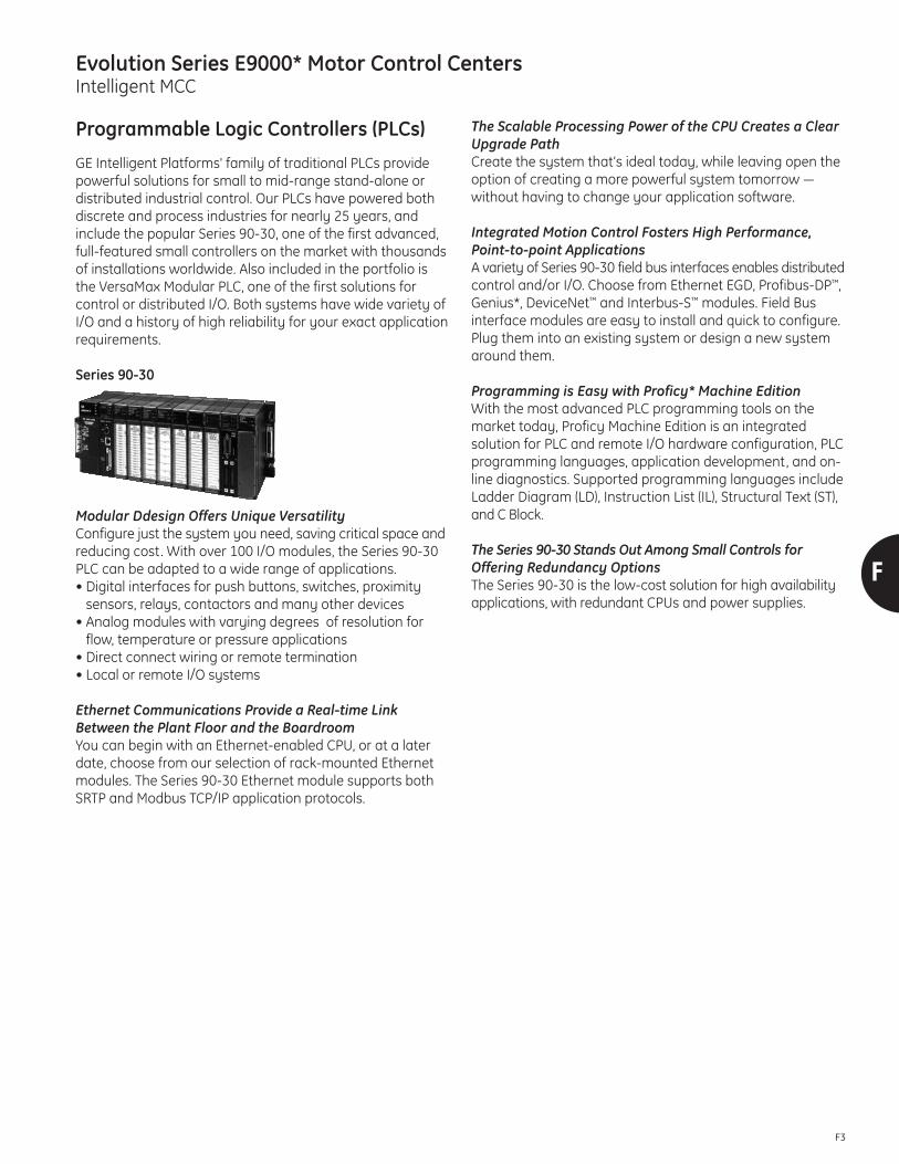
Evolution Series E9000* Motor Control CentersIntelligent MCC
F
F3
Programmable Logic Controllers (PLCs)
GE Intelligent Platforms' family of traditional PLCs providepowerful solutions for small to mid-range stand-alone or distributed industrial control. Our PLCs have powered bothdiscrete and process industries for nearly 25 years, and include the popular Series 90-30, one of the first advanced,full-featured small controllers on the market with thousandsof installations worldwide. Also included in the portfolio isthe VersaMax Modular PLC, one of the first solutions for control or distributed I/O. Both systems have wide variety ofI/O and a history of high reliability for your exact applicationrequirements.
Series 90-30
Modular Ddesign Offers Unique VersatilityConfigure just the system you need, saving critical space andreducing cost. With over 100 I/O modules, the Series 90-30PLC can be adapted to a wide range of applications.• Digital interfaces for push buttons, switches, proximity
sensors, relays, contactors and many other devices• Analog modules with varying degrees of resolution for
flow, temperature or pressure applications• Direct connect wiring or remote termination• Local or remote I/O systems
Ethernet Communications Provide a Real-time Link Between the Plant Floor and the BoardroomYou can begin with an Ethernet-enabled CPU, or at a laterdate, choose from our selection of rack-mounted Ethernetmodules. The Series 90-30 Ethernet module supports bothSRTP and Modbus TCP/IP application protocols.
The Scalable Processing Power of the CPU Creates a ClearUpgrade PathCreate the system that’s ideal today, while leaving open theoption of creating a more powerful system tomorrow —without having to change your application software.
Integrated Motion Control Fosters High Performance,Point-to-point ApplicationsA variety of Series 90-30 field bus interfaces enables distributedcontrol and/or I/O. Choose from Ethernet EGD, Profibus-DP™,Genius*, DeviceNet™ and Interbus-S™ modules. Field Bus interface modules are easy to install and quick to configure.Plug them into an existing system or design a new systemaround them.
Programming is Easy with Proficy* Machine EditionWith the most advanced PLC programming tools on themarket today, Proficy Machine Edition is an integrated solution for PLC and remote I/O hardware configuration, PLCprogramming languages, application development, and on-line diagnostics. Supported programming languages includeLadder Diagram (LD), Instruction List (IL), Structural Text (ST),and C Block.
The Series 90-30 Stands Out Among Small Controls for Offering Redundancy OptionsThe Series 90-30 is the low-cost solution for high availabilityapplications, with redundant CPUs and power supplies.

Evolution Series E9000* Motor Control CentersIntelligent MCC
F4
F
VersaMax*Nano and Micro Controllers
Pick the Palm-Sized PLC That’s Light on Your BudgetFor tight spaces, the VersaMax Nano PLC is the perfect solution. Thanks to its all-in-one construction, installation isa breeze. All you have to do is snap it onto a DIN-rail or screwit into a panel. With the VersaMax Nano, you save on initialas well as life-cycle costs.
Select the Big-Featured PLC in a Compact PackageThe small footprint VersaMax Micro PLC offers the flexibilityof modular design and a variety of built-in features, includingup to 64 I/O points (expandable to 176 I/O points), fast cycletimes, a robust instruction set and extensive memory thatmultiplies your programming options.
Tap the Perfect Solution for Low-end Motion ApplicationsBoth the VersaMax Nano and Micro can be used with eithera PWM or a pulse train device. In addition, both controllerscome with built-in high-speed counters that can be used ineither Type A or Type B configurations. The new Micro 20,Micro 40 and Micro 64 support four 100Khz high-speedcounters and four 65Khz PWM or pulse train out-puts forhigh speed motion applications.
The new MicroMotion expansion module (2 axis of Servo orStepper @ 500Khz pulses/second with encoder inputs) isideal for either Micro integrated motion control or standalonemotion control (over serial or Ethernet networking). The MicroMotion expansion module is loaded with features andsupports 2 axis of stepper and servo control. The modulesupports a powerful function set, Home, Jog, RegistrationInput, S-Curve acceleration, Feedrate Override and more.Up to 256 move profiles are stored on the module andbacked up with the Portable Memory device (removableFlash device) for easy program storage of the motion moves.The Micro 20, Micro 40, and Micro 64 support up to 2 Micro-Motion expansion modules for a total of 4 axis highperformance motion control.
Take Advantage of a Host of Communications OptionsBoth the VersaMax Nano and Micro have an RS-232 portthat can be used for SNP slave, Modbus RTU or serial I/Ocommands. The Micro 23 and Micro 28 also have an RS-485port that adds SNP master and Modbus master commands.With serial I/O commands, you can interface with such devices as pagers, intelligent scales, bar code readers andprinters. The new Micro 20, Micro 40 and Micro 64 have asecond option port that supports either RS-232, RS-485 orUSB communications module. The VersaMax Nano andMicro can easily be networked to Ethernet utilizing the powerful VersaMax SE (Serial to Ethernet module).
Program Your Controllers in Record TimeWith GE’s Proficy* Machine Edition software, programmingyour VersaMax Nano and Micro PLCs is a simple and intuitiveprocess. Mix Relay Ladder Diagram and Instruction List programming within an application. Develop and save customview tables. View PLC and I/O system fault tables on demand.Machine Edition is an automation software breakthrough deploying HMI, motion, and multi-target control in an integrated development environment. This environment provides a common user interface, drag-and-drop editing,and a rich set of development tools. The Micro 20, Micro 40and Micro 64 support a portable program FLASH MemoryModule that provides a simple cost effective way of upgradingfield controllers.

Evolution Series E9000* Motor Control CentersIntelligent MCC
F
F5
VersaMax*Nano and Micro Controllers
Typical Micro 20, Micro 40 and Micro 64 Applications
Material Handling, Packaging and Assembly Machines
Micro 20, Micro 40, Micro 64 AdvantagesFlexible motion control to improve machine throughput isbuilt into controller• Up to 4 axes of stepper or servo control (32bit, 65Khz
Pulse Train)• Up to 4 high speed counters at 100Khz (32bit)
Powerful Networking to improve data gathering• Plug in 10/100M bit Ethernet available• Two built-in communication ports
Simple control for complex applications• 48K bytes of user program memory and 32Kwords of
data storage• Advanced programming instruction set. Ramping, Jog, Find
Home, Go Home, Blended Move (up to 4 continuous moves)• Portable program storage device
MicroMotion Expansion• 2 axis of Servo or Stepper @ 500Khz pulses/second with
encoder inputs• Supports Home, Jog, Registration Input, S-Curve acceleration,
Feedrate Override and more• Interfaces with Micro 20, Micro 40, Micro 64 or standalone
mode using Serial or Ethernet• Stores up to 256 motion profiles on module
SCADA
Micro AdvantagesFlexible Communications from Serial to Ethernet • Modbus Master, Modbus Slave and Report by exception• Modem and Ethernet SRTP or Modbus TCP (Server) option
Abundance of data storage capability • Up to 32Kwords of data storage
Powerful instruction set • Floating point math and PID for process control• Write and Read data to internal FLASH

Evolution Series E9000* Motor Control CentersIntelligent MCC
F6
F
VersaMax*Nano and Micro Controllers
The newest additions to the Micro family – the Micro 20,Micro 40 and Micro 64 PLCs – feature expansion to 132, 152and 176 I/O points respectively, to fast cycle times, robustinstruction sets, and generous memory to allow more flexible programming.
These new Micros each feature an optional second port thatprovides you with an additional RS-232 port, RS-485, USB,or Ethernet. The serial expansion ports come with two analoginput channels. A user-friendly memory module is availableto easily download changes to the controller withoutthe need of a PC.
And it’s all packaged in a sturdy modular design for easy accessand long-term durability. These all-in-one PLCs give youeverything you need to control a wide variety of applications.
Features Nano 10 Micro 14 Micro 23 Micro 28 Micro 20 Micro 40 Micro 64
Built-in Discrete I/O 6 in/4out 8 in/6 out 13 in/10 out 16 in/12 out 12 in/8 out 24 in/16 out 40 in/24 out
Built-in Analog I/O 1 on some models none 2 in/1 out none none none none
I/O Expansion Units none Up to 4 units Up to 4 units Up to 4 units Up to 4 units Up to 4 units Up to 4 units
Logic Memory (Words) 2K 9K 9K 9K 24K 24K 24K
Data Storage (Words) 256 256 2K 2K 32K 32K 32K
Scan Time (msec/K) 1.3 msec 1.1 msec 1.1 msec 1.1 msec 1.1 msec 1.1 msec 1.1 msec
Battery Backed RAM Super Cap only Super Cap only Yes and Super Cap Yes and Super Cap Yes and Super Cap Yes and Super Cap Yes and Super Cap
Real Time Clock none none Yes, Included Yes, Included Yes, Included Yes, Included Yes, Included
Ports Available 1 RS-232 1 RS-232 1 RS-232 and 1 RS-485
1 RS-232 and 1 RS-485
1 RS-232 and second port optionalRS-232, RS-485, USBor Ethernet
1 RS-232 and second port optionalRS-232, RS-485, USBor Ethernet
1 RS-232 and second port optionalRS-232, RS-485, USBor Ethernet
Ethernet Option Yes, VersaMax SE Yes, VersaMax SE Yes, VersaMax SE Yes, VersaMax SE Yes on second port Yes on second port Yes on second port
High Speed CounterUp to 4 at 10Khz (16 bit)
Up to 4 at 10Khz (16 bit)
Up to 4 at 10Khz (16 bit)
Up to 4 at 10Khz (16 bit)
Up to 4 at 100Khz (32 bit)
Up to 4 at 100Khz (32 bit)
Up to 4 at 100Khz(32 bit)
Pulse Train/PWM Up to 4 at 5Khz(16 bit)
Up to 4 at 5Khz(16 bit)
Up to 4 at 5Khz (16 bit)
Up to 4 at 5Khz (16 bit)
Up to 4 at 65Khz (32 bit)
Up to 4 at 65Khz (32 bit)
Up to 4 at 65Khz(32 bit)
Motion Commands N/A N/A N/A N/A
Find Home, Go Home,Jog, Ramp, BlendedMove (4 ConsecutiveMoves)
Find Home, Go Home,Jog, Ramp, BlendedMove (4 ConsecutiveMoves)
Find Home, Go Home,Jog, Ramp, BlendedMove (4 ConsecutiveMoves)
Write Register Valuesto Internal Flush
No Yes Yes Yes Yes Yes Yes
VersaMax Nano and Micro Controllers Selection Guide

Evolution Series E9000* Motor Control CentersIntelligent MCC
F
F7
VersaMax*Nano and Micro Controllers –GeneralI/O Circuits
Standard Input Circuit – 120 Volt AC Input Module(VersaMax IC200MDL240)
Terminals Field Wiring
I/O ConfigurationsStandard I/O for motor control center consists of groupedinput cards and isolated output cards (note that the isolatedoutputs can control NEMA Size 1 to 6 starters).
~
~
A4
~
A5
~
1
3
5
7
9
11
13
15
17
16
14
12
10
18
20
19
8
6
4
A2
A3
NC
NC
NC
NC
NC
NC
NC
NC
NC
NC
H N
H N
H N
H N
H N
~2
A1
1
3
5
7
9
11
13
15
17
16
14
12
10
18
20
19
8
6
4
2
A1
A2
A3
A4
A5
A6
A7
A8
B1
B2
B3
B4
B5
B6
B7
B8
NC
NC
NC
H N~
Rated Voltage 120 Volts ACIndicators One Lcd per pointInputs per Module 16 (1 group with a
single common)Isolation 1500 volts RMS between
field side an logic sideCurrent Draw 50 mA (typical) at rated
voltage from backplane
Input Characteristics:Max. On-state 70 volts to 132 voltsMin. Off-state 0 to 20 voltsMin. On-state 6 mA maximumMax. Off-state 1.5 mA maximumOn response time 1 cycleOff response time 2 cycle
Rated Voltage 120/240 VacOutput Voltage Range 85 to 264 VacOutputs per Module 8 (each output isolated)Isolation 1500 volts RMS between
fieldside and logic side500 volts RMS betweeneach output
Output Current (Max.) 2 amps per point, 5 amps per module
Output Characteristics:Inrush Current 25 amps maximum
for one cycleMin. Load Current 100 mAOutput Voltage Drop 1.5 volts maximumOutput Leakage Current 3 mA maximum at
120 Vac6 mA maximum at240 Vac
On response time 1 ms maximumOff response time 9 ms maximum
(1/2 cycle)
Standard Input Circuit – 120/240 Volt Isolated AC OutputModule (VersaMax IC200MDL331)
Terminals Field Wiring

Evolution Series E9000* Motor Control CentersIntelligent MCC
F8
F
Programmable Automation Controllers
Expanding On Traditional PLCsGE Intelligent Platforms created the concept of the Programmable Automation Controller with the introduction ofour PACSystems* family of automation controllers. Expandingon traditional PLCs, GE's PAC controllers provide a highly reliable, high-performance advanced control platform fordiscrete logic control, motion control, and process control.While GE offers and supports a wide variety of communica-tions protocols to support our customers needs, we havestandardized our control systems on the market-leading industrial network, PROFINET, to provide an extremely highperformance, highly reliable, yet simple to configure and install distributed IO network.
PACSystems* RXi ControllerHigh Performance Distributed IO Controller Platform
GE Intelligent Platforms has leveraged its rich experience inembedded computing and control technology in the designof the innovative PACSystems RXi controller platform. TheRXi Controller incorporates leading-edge CPU technology,the market leading industrial Ethernet network technology,and a unique user interface for maintaining the controller todeliver a control system unique in the industry.
The PACSystems RXi controller is PROFINET enabled, deliveringa small footprint solution with highly flexible distributed I/Ocapabilities to equipment builders and end users. Its uniqueIntelligent Display Module provides configuration and maintenance functions at the controller without software. As a PACSystems controller, the RXi is fully compatible with applications written for any other PACsystems platform. The result is a high performance solution designed fordistributed IO applications.
Higher PerformanceThe RXi Controller is designed for high performance distributedIO applications. With a high performance dual core CPU andGigabit PROFINET (with built in MRP redundancy) and Ethernet ports, every aspect of the RXI has been designedfor performance.
For even more power, the RXi controller can be combinedwith the RXi Modular IPC to deliver a unique control andcomputing platform for the factory floor. Integrated high-speed connectors allow instant data handling. Operator usability can be enhanced by pairing the RXi Modular IPCwith new RXi panel displays with new multitouch technology.
The unique combination of high performance control, integratedPROFINET, intelligent display module, and compact formattruly distinguishes the RXi Controller from other offerings.
Greater UptimeSystems with distributed architectures are easier to configureand maintain. In addition, RXi components are industrialtemperature grade, which combined with patented thermalmonitoring technology and sophisticated passive coolingtechniques delivers reliable control in rugged environments.
Lower Total Cost of OwnershipRXi’s compact control and computing platform allows usersto simplify panel design and reduce the overall size of thepanel while benefiting from the performance, maintainability,and upgradeability of the PACSystems platform. The optionalIntelligent Display Module provides a maintenance touchscreendisplay right on the controller, providing faster interactionwith the controller and simpler start-up.

Evolution Series E9000* Motor Control CentersIntelligent MCC
F
F9
PACSystems* RXi Controller
SpecificationsStorage• 10 MB user memory
Data Retention• RXi specific Energy Pak provides power during power
failure while data is written to NV RAM
Ethernet• 2 Port (shared MAC) GB PROFINET – with MRP• 1 Ethernet (10, 100, 1000 Mbit) port• 1 Ethernet (1000 Mbit) – internal
USB Interface• 2 USB 2.0 Standard Size
Others• SD Card (on Intelligent Display Module or
Intelligence Faceplate)
Power• Input: 24V DC (±25%) with protection
Environmental• Operating: -25°C to +55° C (standard)• Storage: -40°C to +125° C• Operating humidity: 10% to 90%
Mounting• Panel Mount• Dinrail Mount with Optional DIN Mount Plate
Safety• UL, CE• Class 1, Div 2 (pending)
Feature Benefit
COMExpress CPU Technology
Dual core processor for high performance in rugged applications
Rugged technology with wider temperature ranges, higher shock and vibration designs, suitable for industrial applications
Carrier and enclosure designs last across multiple CPU lifespans to provide faster performance enhancements
Integrated redundant PROFINET I/O InterfaceProvides a Gigabit Ethernet I/O network connection with built-in cable redundancy (MRP) delivering IO cabling redundancy with no external switches
High-speed Interconnect Bus Enables truly unique combinations of control and Proficy (or other Microsoft® Windows® or Linux applications)
Built-in Data Storage Internal industrial grade SSD drive provides local long-term data retention
USB and SD interfaces Interfaces enable program loading, serial communications and data storage via standard devices

Evolution Series E9000* Motor Control CentersIntelligent MCC
F10
F
PACSystems* RX3i Controller
The PACSystems* RX3i controller is an incredibly powerfulProgrammable Automation Controller (PAC) in the innovativePACSystems family. The RX3i features a single control engineand a universal programming environment to provide application portability across multiple hardware platformsand deliver a true convergence of control.
With integrated critical control platforms, logic, motion, HMI,process control and high availability based on our ReflectiveMemory technology, the RX3i provides the performance andflexibility to give you an advantage. No matter the challengesyour applications bring, PACSystems RX3i lets you take control.
BenefitsThe innovative technology of the PACSystems RX3i enablesusers to:• Address major engineering and business issues, such as
higher productivity and tighter cost control• Boost the overall performance of their automation systems• Reduce engineering and commissioning costs• Easily integrate new technology into installed base systems• Significantly decrease concerns regarding short- and long-
term migration and platform longevity
Features• High-speed processor and patented technology for faster
throughput without information bottlenecks• Dual backplane bus support per module slot:
— High-speed, PCI-based for fast through put of new advanced I/O
— Serial backplane for easy migration of existing Series 90-30 I/O
• Multiple CPU offerings meeting various performance criteriaup to and including an Intel® 1 GHz CPU for advanced programming and performance with 64 Mbytes memory
• Memory for ladder logic documentation and machine documentation (Word, Excel, PDF, CAD and other files) in thecontroller to reduce downtime and improve troubleshooting
• Open communications support including Ethernet, GENIUS*,PROFIBUS™, HART, DeviceNet™ and serial
• Supports high density discrete I/O, universal analog (TC,RTD, Strain Gauge, Voltage and Current configurable perchannel), isolated analog, high-density analog, high-speedcounter, and motion modules
• Expanded I/O offering with extended features for fasterprocessing, advanced diagnostics and a variety of configurable interrupts
• Hot insertion for both new and migrated modules
High Performance Control on One PlatformThe PACSystems RX3i provides logic, motion, HMI, andprocess control with open communications protocols.• PACMotion modules can control up to 40 high speed axes
in one rack• PACSystems High Availability solution offers true dual
redundancy data synchronization and bumpless transfer• The Control Memory Xchange offers amazing data transfer
at a rate of 2.12 Gbaud
Universal Development EnvironmentThe common software platform across all GE controllers,award-winning Proficy* Machine Edition software providesthe universal engineering development environment forprogramming, configuration and diagnostics for the entirePACSystems family.• Programming tools such as tag-based programming, a
library of reusable code and a test edit mode for improvedonline troubleshooting
• User-friendly environment that can increase design flexibilityand improve engineering efficiency and productivity

Evolution Series E9000* Motor Control CentersIntelligent MCC
F
F11
PACSystems* RX3i Controller
CPUsThe CMU310 is a High Availability redundant CPU that isconfigured using the MaxON software. The CMU310 has thesame functionality as the CPU310. Synchronization of theCMU310s is via an Ethernet link.
BaseplatesThe RX3i Universal baseplates support hot swap capability toreduce downtime. Expansion bases are available in 5 and 10slot versions to maximize flexibility.
Universal Bases Power SuppliesThe RX3i power supply modules simply snap in just like I/O,and they work with any model CPU. Each version providesauto-ranging so there is no need to set jumpers for differentincoming power levels, and they are current limiting so a direct short will shut the power supply down to avoid damageto the hardware.at a rate of 2.12 Gbaud
Discrete I/O ModulesInput modules provide the interface between the PLC andexternal input devices such as proximity sensors, push buttons,switches, and BCD thumbwheels. Output modules providethe interface between the PLC and external output devicessuch as contactors, interposing relays, BCD displays and indicator lamps.
Analog I/O ModulesGE offers easy-to-use analog modules and HART analogmodules for control processes such as flow, temperatureand pressure.
Specialty ModulesThe RX3i features a wide range of Specialty Modules to address specific application requirements. These modules include:• Millivolt and Strain Gage I/O • Thermocouple I/O• RTD I/O • Resistive I/O• Temperature Control • Power Transducer
Networks and Distributed I/O SystemsThe RX3i features a variety of communications options fordistributed control and/or I/O. Choose from Ethernet EGD,PROFIBUS-DP, Genius and DeviceNet. These communicationmodules are easy to install and quick to configure.
RX3i Pneumatic ModuleThis output module provides 11 pneumatic outputs and five24 VDC sourcing outputs. For each pneumatic output, themodule contains an internal 3-way solenoid-actuated valveand an associated output fitting. Solenoid power is suppliedfrom an external 24 VDC source to the“DC Outputs” connectoron the front panel.
Expansion Modules for Local and Remote I/OThe RX3i supports various expansion options for local andremote I/O to optimize configurations. The RX3i can be expanded up to 8 expansion bases using local remote expansion module. The RX3i also supports Ethernet remoteI/O using the RX3i Ethernet Network Interface module(IC695NKT001) Series 90-30 Ethernet Network Interfacemodule (IC693NIU004) for more distributed I/O.
Motion ControlPACMotionThe PACMotion controller is a versatile 4-axis servo motioncontroller that provides the scalability and flexibility to cover afull range of motion applications from small material handlingapplications to complex multi-axis machines and electronicline shaft applications. PACMotion provides real-time synchro-nization of all axes in an RX3i rack. A separate RX3i fast logic scan enables fast deterministic event response andsynchronization, and the demand driven data exchangemodel between the RX3i CPU and PACMotion module manysignificantly reduce scan time impact. The 4-axis servo motioncontroller is built on a high performance hardware platform,with a new enhanced motion engine, operating system, andopen standard integrated programming paradigm.
Baseplates
CPUs Networks andDistributed I/O Motion Modules
Expansion Modules
Discrete I/O Modules
Pneumatic Modules
Power Supplies

Evolution Series E9000* Motor Control CentersIntelligent MCC
F12
F
Example PLC Connections
PLC Controlled StartersA combination motor starter will require a minimum of one Inputand one Output per starter. As shown in Figure 5, the Output is connected between the starter coil and the fused, ungrounded legof the control voltage source (terminals 3, 1). The Input connectionis made between the starter “Seal contact” and the grounded leg of the control voltage source (Terminals 2, X2). The Input monitorsthe status of the seal circuit to independently verify that the starter has closed.
Fig. 5. Input and Output Connection
When an H-O-A switch is used with PLC I/O, the configuration willappear as shown in Figure 6. Note: as mentioned previously, theINPUT monitors the status of the starter’s seal circuit in the manualmode as well as the PLC (automatic) mode.
Starter Units with Individual Control TransformersFor starters having individual control power transformers all Outputsmust be isolated type. This requirement is necessary due to theseparate voltage sources provided by the individual control trans-formers. Inputs may be either isolated or non-isolated types. Wherenon-isolated Inputs are used all X2 terminals must be wired together.
Surge SuppressorsIn cases where excessive noise is present on the control line or hardinterlocks which will operate often (in series with PLC Output), surgesuppressors are recommended.
Optional Inputs/DiagnosticAdditional Input connections can be made to monitor the specificstatus of combination starters and feeders to provide further diagnosticinformation to the process operator and maintenance personnel.1. The status of the overload relay can be monitored. An electrically-
isolated, normally-open auxiliary contact can be ordered withthe GE 300-Line overload relay and an additional PLC Input canbe wired in series with it .
2. A PLC Input can be connected between terminals 1 and X2 tomonitor the availability of control power to the starter unit.
Starter Units with Separate-Source Control VoltageInput and Output connections are shown below (see Figure 7) forunits arranged for separate-source control.
InputA common (non-isolated) Input can be used if all X2 terminals arewired together.
OutputAs required by NEC Article 430-74, if a disconnect auxiliary contactand/or control circuit fuse (FU) is included with each starter, thenthe Output must be the isolated type. However, if the auxiliary contact and fuse are omitted, a common Output module can beused. With common output modules, interposing relays are required with NEMA Size 3 and 4 starters. Note: NEC article 430-74can be met with GE’s standard split-type control terminal boardson all draw-out units, or with GE’s pull-apart terminal boards.
Fig. 7. Input and Output Connections for Separate-Source Control
Isolated Versus Non-Isolated Outputs
Isolated OutputsGE’s isolated Outputs can be used for direct control of NEMA Size 1through 4 combination starters without the use of an interposingrelay. The contactors of GE’s standard NEMA Size 5 and largerstarters are operated at line voltage with interposing relays operated from the secondary of the control transformer.
Non-Isolated OutputsNEMA Size 1-2 starters may be operated directly from common PLCOutput cards. The continuous current rating of GE’s non-isolatedOutput module requires an interposing relay for NEMA Size 3 and largerstarters. Check the module ratings for inrush and continuous values.
Fig. 6. H-O-A Connection

Evolution Series E9000* Motor Control CentersIntelligent MCC
F
F13
Distributed I/O and Remote I/O
GE Intelligent Platforms provides high performance distributedI/O for demanding control applications. Our I/O and Controllersare connected by PROFINET – the market leading industrialnetwork. Using this common interface allows users to mixand match their preferred Controller with the I/O that bestmeets the needs of each part of the applica-tion. Our I/Oportfolio has a wide range of packaging options covering thefull spectrum of needs from simple discrete to high speedanalog control, and from factory automation to process industries with harsh environments. We deliver best in classflexibility, performance, reliability and connectivity.
VersaMax* I/O and Control
Maximum versatility is the guiding principle behind VersaMaxfrom GE Intelligent Platforms. This compact, extremely affordable control solution can be used as a PLC, as I/O, and as distributed control. With its modular and scalable architecture, intuitive features and ease of use, this innovativecontrol family can save machine builders and end usersconsiderable time and money.
Offering Big PLC Power in a Small PackageVersaMax CPUs supply a number of features usually foundonly in PLCs with larger footprints, including up to 64k ofmemory for application programs, floating point math, real-time clock, subroutines, PID control, flash memory, andbumpless program store. The serial ports support serialread/write and Modbus master/slave communications.
An Abundance of Useful I/O OptionsGE offers a broad range of discrete, analog, mixed, and specialty I/O modules. These modules can be freely combinedto create stand-alone I/O stations with up to 256 I/O pointsand expanded I/O systems with up to 4,096 I/O points.
The Perfect Match for Today’s Open SystemsVersaMax gives you the freedom to connect to a wide varietyof host controllers, including PLC, DCS and PC-based controlsystems by way of Genius*, DeviceNet™, PROFIBUS-DP™ andEthernet networks. VersaMax also fully supports the powerand open architecture of GE’s PC Control solutions.
The Ultimate in Cost-effective Control and I/OWith intuitive diagnostics, hot insertion of modules andquick connect wiring, VersaMax extends uptime, reduces engineering and training needs, and dramatically reducesproject life-cycle costs.
A Design that Maximizes Ease of UseEvery aspect of VersaMax has been carefully refined to accommodate the user. Snap-together I/O carriers meanthat no tools are required for module installation or extraction.A convenient rotary switch can be used for setting bus andreducing programming time. With VersaMax, you can evenaddress I/O automatically.

Evolution Series E9000* Motor Control CentersIntelligent MCC
F14
F
PACSystems* RSTiEthernet based I/O delivers high performance andsystem flexibility
To succeed in an outcome-driven world, businesses must operate faster and leaner and be increasingly connected. AtGE Intelligent Platforms, we understand today’s connectedbusiness environment, and are committed to simplifying it.That’s why we’ve designed an automation architecture thathelps you design better machines and plants, operate themsmarter, and redefine the interaction with your equipment.
A pivotal point in this architecture is the I/O. GE Intelligent Platforms leverages industry standards and our experience inembedded technology and high-performance automation todeliver I/O that simplifies system design while reducing costs.
With GE’s Ethernet-based RSTi I/O, communications are enhanced through PROFINET, a high-speed, open protocolthat facilitates the massive amounts of data that devicesgenerate. The RSTI I/O unlocks the potential of continuity,connectivity, and collaboration for your control systems.
Simplifying System Design without Sacrificing PerformanceEquipment builders are continuously looking to improve theperformance of their equipment while augmenting usabilityand reducing size and complexity. These requirements extendto the I/O control system. With PACSystems automationportfolio, GE provides high-performance control solutionswith best-in-class integration of distributed (networked) I/Oideally suited for demanding applications.
The RSTi line of I/O extendds the capabilities of PROFINET enabled GE solutions with a comprehensive line of granularslice I/O that simplifies panel design and reduces the overallsize of the control panel while offering the performance,maintainability and upgradability of the PACSystems platform.
Decentralized I/O Reduces CostThe RSTi decentralized I/O addresses the challenges of highinstallation overhead cost and lack of granularity of a centralized I/O system. The RSTi provides a high performancedistributed I/O network that reduces the cost of field wiring.The distributed nature of the RSTI enables a machine builderto design in sections with distributed I/O drops closer to thefield devices.
Decentralized I/O systems are easily disassembled and re-assembled with a standard, off-the-shelf Ethernet cable versus hundreds of wires coming back to a centralized control cabinet.
The compact RSTi I/O line allows the user to “right size” theapplication, minimizing cost and panel space. I/O expansionis simple with the slide and lock design.
Feature Benefit
PROFINET Connectivity High-speed I/O throughout that connects to hundreds of third-party devices
System Diagnostics Increased uptime by isolating system failures quickly
Powerful Integration Tools Reduced development time with Proficy Machine Edition tools
“Build as You Go” Granular design enables “right sizing” the application, resulting in minimum installation cost and panel space
Rugged Design Rugged “slide and lock” design provides an easy, secure installation
Network IndependenceEight global standard network interfaces supported by the RSTi enables the user to standardize on one I/O system regardless of the bus requirements

Evolution Series E9000* Motor Control CentersIntelligent MCC
F
F15
PACSystems* RSTiDistributed I/O delivers high performance and system flexibility
Powerful SolutionThe RSTi innovative design enables module power, communications and field power to be passed from one module tothe next. Power Distribution, Power Booster and Field Power Isolation modules are available to simplify installationwiring. The RSTI compact design (99 mm high x 70 mm deep x 12mm wide for I/O) reduces panel space.
GE’s high-performance PACSystems RSTi PROFINET enabled family of I/O modules are part of GE’s Intelligent PlatformsHigh Performance Platform strategy. The platform leverages industry standards plus the combination of experience inembedded technology and automation to deliver long-life and higher performance solutions that are easy to configure,manage and upgrade. Contact your local representative for more information about GE’s solutions for your I/O requirements.
Flexible Network Interfaces• PROFINET RT• Modbus TCP/IP• DeviceNet• CC-Link• PROFIBUS DP/V1• Modbus Serial• CANOpen
Over 80 Module TypesAvailable• AC and DC I/O• Relay Outputs• Analog I/O• RTD• Thermocouple• 2, 4, 8 and 16 point density
User Friendly Design• Rugged, removable
terminal block• Tool-less spring clamp
wiring• DIN Rail “slide and lock”
design• Color coded identification• Easy to read LED status• Diagnostic test points
Specialty Modules• Serial communications• High-speed counters• SSI interface• PWM and pulse output
SVDC Module Power andCommunications• Passed from one module
to the next
Field Power• Passed from one module
to the next
Global Standards• CE, UL, CUL approved• UL Class 1 Div 2 and ATEX Zone 2• Temperature range -20°C to 60°C• UL temperature range -20°C to 60°C

Evolution Series E9000* Motor Control CentersIntelligent MCC
F16
F
Genius I/O System
GeneralThe Genius I/O, a system of inherently distributed inputs andoutputs, is designed to interface to any number of industrialcontrollers, including GE Intelligent Platforms PLCs, and thirdparty CPUs. It can be used as the only I/O on a System or itcan be mixed with the present rack-type I/O. Genius representsa complete rethinking of the role of I/O in industrial control.Genius Blocks are UL, CSA, FM and CSA hazardous environmentapproved. The Genius I/O system was made possible throughtwo key GE technological innovations:
Smart Switch: A device with the built-in current and voltagesensors required for the extensive diagnostics available withGenius I/O. The smart switch allows detection of faults notonly within the programmable controller I/O system, butalso faults in the coils and other actuator devices under thecontrol of the programmable controller, as well as the signalpath from pushbuttons and other input devices. No othertechnology provides this level of fault detection.
Communications Controller: A token bus local area networkcontroller which allows Genius I/O devices to communicateover a single-shielded twisted wire pair, rather than via bundlesof point-to-point wires required in conventional systems.
Genius I/O System ArchitectureA simplified block diagram of the Genius I/O System is shownin Figure 2. The PLC, CPU and I/O rack shown are standardSeries 90-70 units. The Genius serial bus connects I/O Blockswith a single shielded twisted pair up to 7500 feet from theBus Controller.
Genius I/O BlockA microprocessor-based, configurable, ruggedized solid-statedevice to which field I/O devices are attached. Measuringapproximately 9" x 4" x 3", I/O Blocks can be mounted virtuallyanywhere, such as in a draw-out unit of a motor controlcenter or pushbutton station where it is common to have oneinput and one output per motor circuit. No separate rack orpower supply is required. Field wiring is attached to a terminalassembly which separates from the removable electronicsassembly. Thus, field wiring need not be disturbed to servicethe electronics. Due to the microprocessor and intelligentswitching, inputs and outputs may be mixed arbitrarily onblocks. There are no dip switches nor replaceable fuses.
An EEPROM (Electrically Erasable Programmable Read-OnlyMemory) is located within the terminal assembly. The EEPROMstores all user-selectable options and retains these selectionseven during Power Off conditions. It can be read by the electronics assembly at any time and altered by commandsfrom either the CPU or the Hand Held Monitor. The EEPROMis the only electronic device in the terminal assembly andhas a long Mean-Time-Between-Failure (MTBF).
The electronics assembly contains the power supply, com-munications chip, microprocessor, smart switches and otherelectronic components required to perform Genius I/O functions.
Each I/O Block is keyed to prevent the insertion of a non-matching electronics assembly into a terminal assemblywired for a different power. Once inserted, the electronicsassembly automatically reads the content of the EEPROMand initializes itself to match the configuration originally established for the I/O Block in that position. Table 1 lists thetypes of I/O Blocks currently available, as well as other basicsystem components.
Typical Genius I/O Unit
Fig. 2. Genius I/O System Block Diagram
Fig. 3. Genius I/O Block Assembly

Evolution Series E9000* Motor Control CentersIntelligent MCC
F
F17
Human Machine Interfaces (HMIs)
The QuickPanel* View FamilyThe QuickPanel View bundled visualization solution providesthe tools required for today’s application needs with a combination of bright touch screen displays, multiple communications options, and Proficy* View – Machine Edition software.
Information DeliveryActing as the bridge between the enterprise system and theplant floor, QuickPanel View provides information, not justdata, that the operators need to run the machines, and thatmanagment needs to run their business. The QuickPanel Viewis a critical link to a well-integrated manufacturing operation.• Built on Microsoft Windows CE operating system• Built-in web server access data and panel using any
standard browser
ScalableAs your information requirements grow, so will your hardwareneeds. QuickPanel View products are exceedingly scalableto grow with your needs.• Broad range of display sizes from 6" to 15"• Choice of Monochrome, Color-STN, or Color-TFT display• Expandable memory and communications options• Easy configuration allows you to run the same program
on different size models
Seamless ConnectivityAs your need to monitor and collect data grows, you mayneed to connect to a wide variety of devices. Unless youroperator interface has seamless connectivity, you may facedelays and headaches. That is why QuickPanel View comesstandard with a large number of built-in drivers to connectwith the the world of automation devices, making it easy toconnect to anything.• Communication drivers over serial and Ethernet• Communication over fieldbus and vendor specific networks
through the addition of a communication expansion card
Other AdvantagesWe invite you to explore the advantages of QuickPanel View.• Cost-effective replacement for push buttons and
pilot lights• Data collection, trending, system security and other functions• Multi-language support• Migration of applications developed with QuickDesigner*• Adherence to global standards UL, ATEX, and CE

Evolution Series E9000* Motor Control CentersIntelligent MCC
F18
F
PACSystems RXi Display/Panel PCMulti-Touch Control and Widescreen Viewing of Industrial Processes
To succeed in an outcome-driven world, businesses mustoperate faster and leaner, and be increasingly connected. At GE Intelligent Platforms, we’ve reimagined automation architecture to help you succeed in today’s business environment.
A pivotal point within this architecture is the displays for operators. GE Intelligent Platforms reconsidered every aspect of an industrial display when developing the PACSystems* RXi Display. From the moment it is unpackedand mounted to when the operator touches its screen, theRXi Display delivers a sleek and powerful user experience.
The RXi Display connects people and machines by combiningthe latest in touchscreen technology with a widescreen display to give operators an enhanced view into theirprocesses. The result is quicker, smarter decisions based onreal-time visualization.
When paired with the RXi Box PC, the RXi Display creates ahigh-performance system that lowers TCO with seamlessreplacement of either component and provides for powerfulupgrades to the underlying computing technology.
High-Performance Display TechnologyThe RXi Display takes industrial displays into today’s connectedworld, combining design, durability, and power in an ultra-slim package designed for the factory floor.
The RXi Display’s modular design means it is built for today —and tomorrow. It helps you design better machines andplants, operate them smarter, and redefine the interactionwith your equipment.
GE knows that today’s rapidly changing industrial environment requires display and computing equipmentthat can evolve along with your operations. The RXi Displayand RXi PC system doesn’t become obsolete — upgrade thePC as chip technology accelerates. The result is increasedperformance and productivity, and decreased TCO.
User-Friendly Design Increases ProductivityThe RXi Display was designed for ease of operation. For example, its front-mounted SD memory card slot can be accessed without opening the cabinet.
For fast and easy installation, the RXi family of displays offersa unique mounting system, designed to be completed by asingle person without the need for special tools or fasteners.Your system is up and running in minutes.
Enhanced Durability and Touchscreen ControlThe RXi Display’s solid aluminum bezel design is built to last.Its 9H-rated hardened projected capacitive multi-touchscreen provides an intuitive, smartphone-like experience. Theresponsive, clear-glass display allows operators to efficientlynavigate software in a variety of industrial environments.
Capacitive touchscreen technology is more resistant tophysical damage and UV discoloration, and permits a higherdegree of brightness and contrast as compared to standardresistive technology. This means you get clear, easy-to-seevisualization of your process.
Feature Benefit
Widescreen Technology Allows operator to view more processes or information on one screen
Multi-Touch Screen Interface Easier on-screen navigation enabling familiar smartphone-like experience
External Memory Slot SD Card Slot can be accessed from front of panel without opening cabinet
Captive Mounting Hardware One person can quickly install the display without special tools.

Evolution Series E9000* Motor Control CentersIntelligent MCC
F
F19
envisage*Energy Management System
envisage MonitoringThe envisage Monitoring module displays real-time powerand demand data from remote intelligent energy devices as well as facility-wide infrastructure systems.
A birds-eye graphical site diagram provides a model representation of the complete facility and leads quickly tomore detail in dynamic one-line schematics for the site location and even individual installed devices and monitoredvalues. It keeps you completely and accurately informed ofthe system’s status in real-time – both locally and remotely –through customized views that aggregate and scale theinformation you need. Energy monitoring includes trenddata from meters, relays, and breaker trip units in order toanalyze the power system. It allows you to highlight andacknowledge unusual activity and alarm conditions with the real-time and historical alarm viewers to ensure that problems do not go unnoticed.
Typical Monitored Values• RMS current • Current demand• Peak current• RMS voltage • KW and KWh• Peak KW demand• Apparent power (KVA) and apparent energry (KVAh) • Reactive power (KVA) and reactive energry (KVARh) • Power factor• Frequency• Event records• Additional system parameters — water, air, gas,
electric, steam, HVAC, backup power, security• Switch position and breaker status
Typical Connected Devices• Meters • Trip units• UPS• Solar chargers • CRAC units• ATS• PSG• PDU • Generators• VFD• PLC• Proactive relays• “Smart” power strips
Overview of entire network

Evolution Series E9000* Motor Control CentersSolid-State Drives & Starters
G
G1
Adjustable Frequency AC DrivesGeneral Application Notes
As a vehicle for controlling multiple motor functions, theMotor Control Center has become the logical place to mountvariable speed drives. However, the application of thesedrives is not a simple selection process, and the following isan explanation of some of the variables involved.
A drive must have ventilation. The basic power switchingcomponents are transistors, which are mounted on finnedheat sinks. Although the drive may be operating at 95% orgreater efficiency, the 5% (±) normal heat loss cannot be enclosed in the MCC without exceeding the safe operatingtemperature (50°C). Standard mounting is ventilated (NEMA1 or 1A only).
A drive is electronically controlled. The new generation ofPWM drives are all microprocessor based. Although wellshielded from stray noise, they require careful wire routing,and in some cases shielded wire runs to avoid “nuisance”problems. Control wires should be run separate from powerleads. If they must cross, try to keep them at right angles tominimize the induced electric fields (noise).
A drive creates noise on the power system. Although we useline reactors to minimize system disturbances, a drive willcreate harmonics on the power/system (both at the motorand at the transformer). If sensitive computer systems are tobe utilized, they should be isolated from the drive’s source,or EMI/RFI filters added. Likewise, the harmonics created atthe motor may cause the motor to run hotter than expected.Standard motors should be derated 10% when used with adrive. We recommend high efficiency motors for drive applications as a minimum. See motor application data, SH,page G3.
A drive must have short circuit protection. Since a drive is subjected to higher available short circuit currents in anMCC, (vs. a wall mounted unit) additional components suchas current limiting fuses and reactors are utilized. See typicalone line sketch.
A drive can provide significant energy savings.When a fan orpump is utilized on a system with variable flow rates, whethermeasured in gallons per minute or cubic feet of cooling airper minute, a variable speed drive is the most efficient meansof control. Since a variable torque load requires significantlyless energy when operated at lower speed, the energy savingscan be in the 25 to 50% range when compared to a full voltage
motor using dampers or valving to reduce its output. (Theamount of savings depends, of course, on the amount oftime the motor can be used at the reduced speed.) It will alsolower demand charges due to reduced motor starting current.
Line ReactorsThe available power source connected to the Drive is not toexceed 500kVA. If the AC power source is greater than500kVA and the Drives rating (HP) is less than 10% of thepower source's kVA; AC line reactors will have to be installedin L1, L2, and L3 power leads of the Drive. We provide 3% Linereactors as standard but they can be deleted as an option.The drive internally has a DC reactor, which will protect thedrive components.
Load FiltersIGBT drives create voltage spikes at the motor. Motor insulationrating must be higher than these peaks. Motor should meetNEMA MGI part 31. If not, load filters may be required. Referto page G4.

Evolution Series E9000* Motor Control CentersSolid-State Drives & Starters
G2
G
Adjustable Speed DrivesAF-600 FP & AF-650 GP Series
Adjustable Frequency DriveThe AF-600 FP is an AC packaged drive that provides thefunctionality required for variable torque loads such as fans,pumps and compressors. Forward/Reverse and Simple commands from the local or remote keypad or from the facility management system, along with pre-loaded motorparameters and factory defaults, allow for quick and ready-to-go installation. The E9000 offers expanded horsepowerratings in 230Vac (1/4 to 50Hp), 460Vac (1/2 to 500Hp) and575Vac (1-500Hp) for even greater range of application.
The AF-650 GP Adjustable Frequency Drive with flux vectorand dynamic torque-vector control using optimized controlof voltage and current vectors provides the enhanced performance that you are looking for in your application. TheAF-650 GP process control systems will make any task simpleand profitable. In addition, by adding an optional (encoder)speed feedback device, this drive can be configured to operatein a flux vector control mode. The AF-650 GP provides flexibilityacross a wide range of constant torque applications.
The AF-600 FP and AF-650 GP series have an array of functionsthat provides significant benefits. Standard features include:auto-tuning without having to rotate the motor, built in PIDcontrol, rotating motor pick up control (catch spinningmotor), Standard RS485 (Modbus RTU), Metasys or ApogeeFLN P1 Communications, automatic energy-saving operation(which minimizes drive and motor loss at light load) and otherfunctions to combine performance and energy savings. Thenew generation IGBT means reduced electrical noise andless voltage spiking. On-line-tuning provides a continuouscheck for variation of motor characteristics during runningof high-precision speed control. All drives conform with thefollowing safety standards: UL, cUL, CE and C-Tick.
AF-600 FP AF-650 GP

Evolution Series E9000* Motor Control CentersSolid-State Drives & Starters
G
G3
Adjustable Speed Drives
Standard Specifications AF-600 FP & AF-650 GP Environmental Conditions Enclosures IP20 Chassis, IP00 Chassis, NEMA 1 kit available Installation Location Do not install in locations where product could be exposed to dust, corrosive gas, inflammable gas, oil mist, vapor,
water drops or direct sunlight. There must be no salt in the atmosphere. Condensation must not be caused by sudden changes in temperature. For use ataltitudes of 3280 ft. (1000M) or less without derating.
Storage Temperature -25° to 65°C Ambient Temperature -10° to +50°C (24 hour average max of 45°C) Ambient Humidity 5 to 95% RH (non-condensing) Vibration 1 g. Cooling Method Fan Cooled all ratings. Fan Control Auto, 50% level, 75% level, 100% level adjustable Standards / Approvals CE, UL, cUL, and C-Tick Suitable for use on a circuit capable of delivering not more than 100,000 rms symmetrical
amperes for 230V and 460V Input Power Supply Rated Input AC Voltage 200-240 Vac, 3-phase, 50-60 Hz, +/- 10% V, 380-480 Vac, 3-phase, 50-60 Hz, +/- 10% V, 525-600 Vac, 3-phase,
50-60Hz, +/- 10% V, 525-690 Vac, 3-phase, 50-60 Hz, +/- 10% V Maximum Voltage Imbalance 3% of rated supply voltage True Power Factor > 0.9 nominal at rated load Displacement Power Factor > 0.98 Switching On Input Power Supply Maximum twice/minute up to 10HP, Maximum once/minute above 10HP Environment According to EN60664-1 Overvoltage category III/pollution degree 2 DC Link Reactors Built-In DC Link Reactors on all ratings RFI Filters Built-In RFI Filters to reduce noise generated by the drive. Meets industrial standards. Output Rated Output Voltage 0-100% of supply voltage Output Frequency 0-590 Hz; 0-590Hz for 460V above 100HP and 525/600/690 V above 50HP Switching on output Unlimited Accel/Decel Times 0.01-3600 seconds Control Method Sinusoidal PWM Control (V/Hz, Avd. Vector Control, Sensorless Vector, and Flux Vector with motor feedback) Control Starting Torque 160% starting torque for 1 minute (constant torque), 110% starting torque for 1 minute (variable torque) Carrier Frequency (Motor Noise Selectable - 1, 1.5, 2, 2.5, 3, 3.5, 4, 5, 6, 7, 8, 10, 12, 14, 16 kHz Torque Boost AF650 GP-Selectable by up to 5 individual V/Hz settings in V/Hz Mode or by 0 - 300% setting of Torque Boost parameter
in Adv. Vector Mode. AF600 FP- 0 - 300% setting to compensate voltage in relation to the load at low speed. Acceleration / Deceleration Time 0.01-3600 seconds (4 acceleration and deceleration times are selectable via digital inputs. Acceleration and
deceleration patterns can be selected from linear or S-curve). Data Protection Password Protection for Quick Menu or Main Menu, 0-9999. Pattern Operation Settings via Built-In Logic Controller Sequencer Jump Frequency Control 4 jump (or skip) frequencies via parameter set to avoid mechanical vibration Slip Compensation Maintains motor at constant speed with load fluctuations Torque Limit Control Output torque can be controlled within a range of 0.0 to 160% (0.1 and steps) Preset Speeds 8 programmable preset speeds selectable by 3 digital inputs Built-In Communications Drive RS-485, Modbus RTU, Metasys N2, or Apogee FLN P1 Trim Reference Setting Available for speed reference offset via potentiometer, voltage input, or current input DC Injection Braking Starting frequency: 0.0-590 Hz, 0-590Hz for 460V above 100HP and 525-690 V above 50HP Braking time:
0.0-60.0 seconds Braking level: 0-100% of rated current Jogging Operation Operation via On key or digital input (Fwd or Rev). Auto-Restart After Power Failure Restarts the drive without stopping after instantaneous power failure Energy Savings Controls output voltage to minimize motor loss during constant speed operation Start Mode Function This functionality smoothly catches a spinning motor Real Time Clock Built-In with programmable timed actions Logic Controller (LC) Sequencer Logic Controller Events Up to 37 types of Programmable Events Comparators Array of 6 Comparators Timers Array of 8 Timers, adjustable from 0.0 to 3600 sec Logic Rules Array of 6 Boolean Logic Rules Logic Controller States Array of 20 Logic Controller Action States Process Controller (PID) Process CL Feedback Select Up to 2 references. Selectable - No function, Motor Feedback, Separate Encoder, Encoder Option Module, or
Resolver Option Module Process PID Control Normal or Inverse Process PID Anti Windup Disabled or enabled Process PID Start Speed 0.0-200 Hz Process PID Proportional Gain 0.00-10.00 Process PID Integral Time 0.1 - 10000.0 ms

Evolution Series E9000* Motor Control CentersSolid-State Drives & Starters
G4
G
Standard Specifications AF-600 FP & AF-650 GP (continued)
Process PID Differential Time 0.0 - 10 s Process PID Differential Gain 1.0-50.00 On Reference Bandwidth 0-200% Operation Operation Method Keypad operation: Hand, Off, Auto Digital Input: Programmable for Start/Stop, Forward/Reverse, Jog Timer
operation: Stop after predetermined time frame. USB Port for programming drive with optional PC Software Frequency Reference Signal Left or Right Arrow buttons on keypad in Manual Mode Speed Potentiometer: 0 to +10 Vdc, 10 to 0 Vdc,
0- 10Vdc analog input 0/4-20ma analog input References Up to 3 Input References can be selected from Analog Input #1 or #2, Frequency Input #1 or #2, Network, or
Potentiometer Input Signals Signals 6 - Digital Inputs, 24 Vdc PNP or NPN, 1 - Safe Stop Digital Input suitable for category 3 installations to
meet EN-954-1, 2 - Pulse Inputs rated to 110kHz or 1 - Pulse Input and 1 - Encoder Input 24 Vdc rated to 4096 PPR 2 - Analog Inputs -10 to +10V scalable or 0/4 to 20 mA scalable. Digital Input Settings: No Operation, Resetafter drive trip or alarm, Drive at stop with no holding current, Quick Stop according to Quick Stop Decel Time 1,Stop on input going low, Start, Maintained Start after signal applied for Minimum of 2ms, Reversing, Start Reverse,Enable Start Forward only, Enable Start Reverse only, Jog, Multi-Step Frequency selection (1 to 8 Steps), Hold DriveFrequency, Hold Reference, Speed Up; activated by Hold Drive Frequency, or Hold Reference, Slow Down; activatedby Hold Drive Frequency or Hold Reference, Drive Parameter Setup Select 1-4 Precise Start or Stop; Activated whendrive parameter, precise start or stop function is selected, Catch Up or Slow Down; Activated by signal to add to orsubtract from input reference to control speed,Pulse Input selectable from 100 - 110000Hz, Accel / Decel Time select.Set Input to Accel / Decel Times 1 to 4, Digital Potentiometer Input Increase or Decrease, Mechanical Brake Feedback.
Output Signals 2 - Digital Outputs 24 Vdc (Digital Outputs are used in place of 2 of the Digital Inputs), 2 - Form C Relays rated to 2A at 240 Vac, 1 - Analog Output 0/4 to 20mA, Relay Output Settings : No Operation, Control Ready, Drive Ready,Drive Ready in Remote, Standby No Drive Warnings, Drive Running, Drive Running No Drive Warnings, Drive Running on Remote, Alarm, Alarm or Warning, At Torque Limit, Out of Current Range, Below Current, Above Current, Out of Speed Range, Below Speed, Above Speed, Out of Feedback Range, Below Feedback, Above Feedback, Thermal Overload Warning, Reverse, Bus OK, Torque Limit and Stopped, Brake and no Warning, BrakeReady and No Faults, Brake Chopper Fault, External Interlock, Out of External Reference Range, Below ExternalReference, Above External Reference, Fieldbus Controlling Drive, No Alarm, Running in Reverse, Local Mode Active,Remote Mode Active, Start Command Active, Hand Mode Active, Auto Mode Active
Protective Functions Line Phase Loss, DC Overvoltage, DC Undervoltage, Drive Overload, Motor Overtemperature, Motor ThermistorOvertemperature, Torque Limit, Overcurrent, Ground Fault, Short Circuit, Control Word Timeout, Brake ResistorShort-Circuited, Brake Chopper Short-Circuited, Brake Check, DC Link Voltage High, DC Link Voltage Low, InternalFan Fault, External Fan Fault, Power Board Overtemperature, Missing U Phase, Missing V Phase, Missing W Phase,Internal Fault, Control Voltage Fault, Auto Tune Check - Wrong Motor Parameters, Auto Tune Low Inom - Motorcurrent is too low, Current Limit, Mechanical Brake Low, Drive Initialized to Default Value, Keypad Error, No Motor,Soft Charge Fault, Auto Tuning Fault, Serial Comms Bus Fault, Hardware Mismatch, Speed Limit.
Keypad Keypad Features LCD Display with 6 Alpha-numeric lines. Multi-Language Support, Hot Pluggable, Remote Mount Option, and
CopyCat Feature, IP65 rating when remote mounted on enclosure, LED’s - Green - drive is on, Yellow - indicates a warning, Red - indicates an alarm, Amber - Indicates active Menu keys and H-O-A keys
Keypad Keys Status - shows status of drive, Quick Menu - Enters Quick Start, Parameter Data Check or Trending Modes, MainMenu - Used for programming all drive parameters, Alarm Log - Used to display Alarm list, Back - Reverts to previous step or layer in parameter,structure, Cancel - Used to cancel last change or command, Info - Displays information about a command arameter, or function in any display. Hand/Off/Auto - Used to control drive locallyor put drive in remote mode, Reset - Used to reset Warnings or Alarms.
Password 2 Level Password Protection Alternate Motor Parameters Up to 4 Separate complete parameter set-ups are available Graphical Trending Trend Speed, Power, Frequency or any value programmed in status display RS485 Modbus RTU Serial Communications Physical Level EIA/RS485 Transmission Distance 1640 ft (500m) Node Address 32 Transmission Speed 2400, 4800, 9600, 19200, 38400,or 115200 (bits/s) Transmission Mode Half Duplex Transmission Protocol Modbus RTU Character Code Binary Character Length 8 Bits Error Check CRC Special AF650 FP Modes Fire Override Mode Overrides drive’s protective features and keeps motor running Pump Cascade Controller Distributes running hours evenly over up to 4 pumps. Sleep Mode Drive detects low or no flow conditions and adjusts outputDry Pump Detection Detects pump operation and can set off alarm, shuts off, or other programmed actionsBelt Monitoring Drive can detect relationship between current and speed to recognize a broken belt

Evolution Series E9000* Motor Control CentersSolid-State Drives & Starters
G
G5
AF-600 FP & AF-650 GP Standard Options
AF-600 FP & AF-650 GP Additional Options
Line Reactor 3% Reactor is standard with the drive DC Link Reactors Standard with drive Class AFII RFI Standard with drive Speed Control The unit comes with a Keypad that can be used for Speed adjustment. Outputs Relays Drive come standard with two relays form C rated to 2A at 240 VAC. Outputs Analog Drive comes standard with 1 Analog output 0/4-20mA Outputs Digital Drive comes standard with 2 Digital outputs at 24 VDC (Digital Outputs are used in place of the 2 Digital inputs. Communications Drive RS-485, Modbus RTU, Metasys N2, or Apogee FLN P1
Line Reactor 5% Reactor must be requested and priced Speed control Door mounted potentiometer must be requested and priced. Communication Module Profibus Profibus DP internal mounted module for use on AF-650 GP & AF-600FP. Supports Profibus DP V1 communications
networks. DeviceNet DeviceNet internal mounted module for use on AF-650 GP & AF-600FP. ODVA certified device. Ethernet IP Ethernet IP internal mounted module for use on AF-650 GP & AF-600FP. ODVA certified device. Features 2-Port
built-in switch. Also includes webserver and email notification. 1Requires I/O and network slots and cannot beused with any other network or I/O modules
Modbus TCP Modbus TCP internal mounted module for use on AF-650 GP & AF-600FP. ProfiNet RT ProfiNet RT internal mounted module for use on AF-650 GP & AF-600FP. LonWorks LonWorks internal mounted module for use on AF-600 FP drives only. Supports LonWorks building automation
communications networks BacNet BacNet internal mounted module for use on AF-60 FP drives only. Supports BacNet MSTP building automation
communications networks. Relay Output Relay Output internal mounted module for use on the AF-650 GP and AF-600 FP. Module adds (3) Form C relay
outputs to the drive. Relays are rated at 2A at 240V resistive load. Analog I/O Analog I/O internal mounted module for use on the AF-600 FP drive only. Module Includes: 3 - Analog Inputs
0-10V, 0/4-20mA & 3 - Analog Outputs 0-10V, Battery Back-Up power for AF-600 FP’s internal Real Time Clock 24V DC External Supply 24V DC External Supply internal mounted module for use on the AF-650 GP & AF-600 FP drives. This module
accepts an external 24V DC supply which is used to keep the control board of the drive and other option modules powered in the event of a Line side power outage. Can be used with Communications and I/O Modules.
General Purpose I/O General Purpose I/O internal mounted module for use on AF-650 GP and AF-600 FP drives. Module includes: 3 - 24V Digital Inputs, 2 - PNP/NPN Digital Outputs, 2 - 0-10V Analog Inputs & 1 - 0/4-20mA Analog Output
Encoder Encoder internal mounted module for use on the AF-650 GP. Module supports all 5V incremental encoders. Also supports Hyperface SinCos encoders.
Resolver Resolver internal mounted module for use on the AF-650 GP drive. Module supports 4-8Vrms, 2.5kHz - 15kHz,50mA resolvers. Resolution is 10bit at 4Vrms.
Safe PLC I/O Safe PLC I/O internal drive mounted module for use on the AF-650 GP drive. This module provides a safety inputbased on a single pole 24V DC input.

Evolution Series E9000* Motor Control CentersSolid-State Drives & Starters
G6
G
Adjustable Speed DrivesSpace Height & Assembly
AF-600 FP & AF-650 GP Space Height, 42 kAIC
(1) Section 2 will always be on the left and bottom mounted. All Space height is based on all main bus sizes. (2) When line reactors are not required consult factory for dimensions. (3) Pilot devices may impact the X height on certain plug-in HPs
Minimum UL short-circuit rating 42KAIC@ 480V
AF-600 FP & AF-650 GP Space Height, 65 kAIC
(1) Section 2 will always be on the left and bottom mounted. All Space height is based on all main bus sizes. (2) When line reactors are not required consult factory for dimensions. (3) Pilot devices may impact the X height on certain plug-in HPs
Minimum UL short-circuit rating 65KAIC@ 480VMinimum UL short-circuit rating 65KAIC @ 600V for all buckets rated 575/600 V
Function Plug-InMax HP GP/FP CT/VT @
DisconnectSection 1 Section 2
208V 230/240V 380/415V 440/480V 575/600V Width X Height Width X Height
Basic ,LR,Bypass
& Isolation
X 5/5 5/5 3/3 5/5 SELI, SELT 15 2.5
X 5/7.5 10/10 SELI, SELT 15 3
X 10/15 10/15 15/15 20/25 SELI, SELT 15 4
25/40 25/40 40/60 60/60 SELI, SELT 24 4
/75 SELI, SELT 24 5.5
40/ 40/ SELI, SELT 30 5.5
50/60 50/60 SFLI, SFLT 30 5.5
75/ 75/ SELI, SELT 24 5.5 15 1.5
/75 100/125 SFLI, SFLT 24 5.5 15 1.5
100/125 150/200 SGLI. SGLT 30 5.5 24 1.5
200/250 300/ SGLI. SGLT 30 5.5 30 4.5
Function Plug-InMax HP GP/FP CT/VT @
DisconnectSection 1 Section 2
208V 230/240V 380/415V 440/480V 575/600V Width X Height (3) Width X Height (1)
Basic & LR
X 3/3 3/3 3/3 5/5 SELI, SELT 15 2
X 10/10 SELI, SELT, TECL 15 2
X 10/15 10/15 15/15 20/25 SELI, SELT 15 3
X 20/25 SELI, SELT, TECL 15 3
X 15/20 15/20 30/30 40/50 SELI, SELT 15 4
X 40/50 SELI, SELT, TECL 15 4
25/40 25/40 40/60 60/75 SELI, SELT 24 4
60/75 SELI, SELT, TECL 24 4
40/ 40/ 75/ SELI, SELT 24 4.5
/75 100/125 SFLI, SFLT 24 4.5
75/100 SELI, SELT, TECL 24 4.5
100/ 150/ SFLI, SFLT 30 5.5
200/250 300/350 SGLI, SGLT 30 5.5 20 3
350/350 500/500 SKLI, SKLT 30 6 24 6
500/500 SGLI, SGLT 30 6 24 3.5

Evolution Series E9000* Motor Control CentersSolid-State Drives & Starters
G
G7
Six Pulse VFD Generic Block Diagram
Control Logic
Logic to Power Interface
Power Section
Soft Charge Circuitry
L1
L2
L3
T1
T2
T3
Rectifier(SCR/DIODES)
InverterSection (GBTs)
IntermediateCircuit
Adjustable Speed DrivesSpace Height & Assembly
AF-600 FP & AF-650 GP Space Height, 100 kAIC
(1) Section 2 will always be on the left and bottom mounted. All Space height is based on all main bus sizes. (2) When line reactors are not required consult factory for dimensions. (3) Pilot devices may impact the X height on certain plug-in HPs
Minimum UL short-circuit rating 100KAIC@ 480V
Function Plug-InMax HP GP/FP CT/VT @
DisconnectSection 1 Section 2
208V 230/240V 380/415V 440/480V Width X Height (3) Width X Height (1)
Basic ,LR,Bypass with
J-Fuse (2)
X 5/5 5/5 3/3 5/5 SEPI, SEPT 15 2.5
X 5/7.5 10/10 SEPI, SEPT 15 3
X 15/20 15/20 30/30 40/50 SEPI, SEPT 15 4
40/ 40/ SEPI, SEPT 30 5.5
50/60 50/60 SFPI, SFPT 30 5.5
75/ 75/ SEPI, SEPT 24 5.5 15 1.5
100/125 SFPI, SFPT 24 5.5 15 1.5
100/125 150/200 SGPI, SGPT 36 4.5 15 3
200/250 300/350 SGPI, SGPT 36 5.5 30 4.5

Evolution Series E9000* Motor Control CentersSolid-State Drives & Starters
G8
G
Adjustable Speed Drives
Drive Configuration in Motor Control Center ConstructionCircuit Breaker or Fusible Switch Required for Disconnect
STANDARD VFD
VFD WITHLINE ISOLATION
VFD WITHLINE ISOLATIONPLUS BYPASS FEATURE
VFD WITHBYPASS FEATURE
STAB(1)
(2)
CB REACTOR VFD (3) * MOTOR
MC
C B
US
STAB(1)
(2)
CB REACTOR VFD (3) * MOTOR
MC
C B
US
STAB(1)
(2)
CB REACTOR VFD (3) * MOTOR
MC
C B
US OL
STAB(1)
(2)
CB REACTOR VFD (3) * MOTOR
MC
C B
US OL
(1) Drawout breaker through 600A(2) J Fuse as required(3) DC link reactor (choke) included in drive
* Load Filter option

G9
Evolution Series E9000* Motor Control CentersSolid-State Drives & Starters
G
Adjustable Speed DrivesHarmonic Filters
GE offers two basic filter types in MCC construction: Matrixand Dynamic Current Injection. Consult factory for sizing.
GE Matrix Harmonic Filters provide broadband reduction ofharmonics. They not only offer better performance overother broadband filtering and 12- and 18-pulse harmonicreduction techniques, they also are suitable for a widerrange of applications. Matrix Harmonic Filters can be in-stalled in either variable or constant torque drive applicationsand can be applied on either a six pulse or half-controlledrectifier. For applications other than variable torque, contactthe factory for filter selection.
GE Matrix Harmonic Filters enable most AC drive systems tocomply with the voltage and current distortion limits outlinedin IEEE 519. A complete harmonic analysis and productselection tool is available at www.gedigitalenergy.com. Select Digital Energy > HV/MV Equipment > Capacitors > LVPower Factor Correction > Matrix Harmonic Filter or simplyuse this “link”.
GE Matrix Harmonic Filters are multi-stage low pass filtersspecially configured to avoid the attraction of harmonicsfrom other sources on a shared power system. They will notcause power system resonance. However, the configurationof the filter requires that only drives or equivalent loads beloaded on the output. One filter can be used with multipledrives, but if there is a drive bypass circuit, there must beone filter per drive and the filter and drive combination mustbe bypassed.
GE GEMActive Dynamic Current Injection Filters for harmoniccancellation and power factor correction:• Reduce harmonics for IEEE 519 (1992) standard compliance• Decrease harmonic related overheating of cables,switchgear and transformers
• Reduce downtime caused by nuisance thermal tripping ofprotective devices
• Increase electrical network reliability and reduce operatingcosts
• Compensate each phase independently • Are UL approved • Offer parallel connection for easy retrofit and installationof multiple units for large networks
• Filter to the 50th order harmonic • Filter entire network or specific loads depending on installation point
• Respond to load fluctuations in 40 microseconds with 8milliseconds for full response to step load changes
• Feature IGBT based power electronic technology • Come in 50, and 100A models for 208-480V, 50/60 Hz,three phase networks that can be paralleled to match loadrequirements
GE GEMActive reduces problematic harmonic levels and provides instantaneous power factor correction. Cost savings result from reduced downtime and maintenance. Inaddition, over-sizing of distribution equipment to provide forharmonics and poor power factor can be avoided. GEGEMActive dynamically corrects power quality by providing:Active Harmonic Filtration, Resonance Prevention, PowerFactor Correction and Dynamic VAR Compensation

Evolution Series E9000* Motor Control CentersSolid-State Drives & Starters
G10
G
Adjustable Speed DrivesMotor Application Data
Harmonic DeratingAC motors have traditionally been applied as constant speedmotors, so there is little published information on reducedspeed efficiencies, especially when operated with a non-sinusoidal supply such as an inverter. The harmonicspresent in the PWM inverter output increase motor lossesand thus motor heating. GE Energy Saver* motors, designedfor high efficiency and improved thermal characteristics,may be applied at nameplate rating for variable torque duty,such as centrifugal fans and pumps, for 4 and 6 pole ratings.Standard AC motors designed for 60 Hertz operation shouldbe derated 10% for variable torque duty. For constant torqueapplications, Energy Saver and standard design motorsshould be applied per Fig. 1. For other applications refer tothe Company.
Fig. 1
How to Select Drives
1. Types of LoadIn selecting inverters, load patterns of machines should be knownin advance. Generally, loads can be categorized into the three typesshown below. Estimate or obtain the point marked 0 as indicated.This defines maximum torque and the maximum or minimumspeed requirement of the driven equipment. Calculate the requiredmotor HP by substituting the maximum torque and rated motorbase speed in equation (1).
(1)HP = TXN 5250HP = Required HPT = Torque in lb./ft.N = Speed in RPM
Select the proper motor using the data from motor applicationbrochures, identify the motor full load current and select the inverterwhich meets or exceeds the motor full load current requirements.
2. Motor Speed RangeMotor synchronous speed is determined by the following equation: FrequencySync. Motor Speed = 120 X Applied Number of Motor Poles
Induction motors operate at a somewhat slower speed than synchronous speed due to slip, which is generally 2-3 percent ofsynchronous speed.
If the application requirements call for higher or lower speeds than canbe obtained by using standard motors following these applicationguidelines, gear increasers or reducers should be considered.
3. Multi Motor DrivesMultiple motors can be driven simultaneously by one drive unit. Inorder to select the proper inverter, total the individual motor full loadcurrents and multiply the sum by a factor of 1.1. Select the inverterthan can deliver the total current calculated. Each motor will requireindividual overload relays, when switched independently RTF.
4. Acceleration TimeAcceleration time is programmable. If the programmed setting callsfor a faster acceleration than the drive system is capable of, theunit may trip due to an overcurrent condition. Therefore, the actualtime to accelerate the driven load should be calculated using thefollowing equation and the acceleration time setting should be ad-justed accordingly. (Wk2 X ΔN)TA = 308 (T X 1.2)Where:TA = Time to accelerate the driven load (in seconds).ΔN = Change in speed (in RPM)WK2 = The total system inertia reflected to the motor shaft.
Includes motor, machine gears (in ft./lbs.2)T = Motor full load torque (lb./ft.)
When using a drive in a conventional constant speed machine application where a full voltage starter has been used, the acceler-ation time should be set longer than the original machine. This isbecause the maximum allowable current that the AF-650GP drivecan deliver is 150 percent of rated current, while full voltagestarters deliver 600-800 percent. This means that the drive deliversa “soft start” and thus reduces starting torque over that of a fullvoltage starter, which naturally yields a longer acceleration time.
MOTOR SPEED (MAX.)
MOTOR SPEED (ZERO) ACCELERATION TIME
ADJUSTABLE
TIME
TOR
QU
E 1
00%
VARIABLETORQUE
SPEED HZ 100%
TOR
QU
E 1
00%
CONSTANTTORQUE
SPEED HZ 100%
TOR
QU
E 1
00%
CONSTANTHORSEPOWER
SPEED HZ 100% 150%
0 100 150% SPEED
100
% T
OR
QU
E
ENERGY $AVER TYPE KE
STANDARD K

Evolution Series E9000* Motor Control CentersSolid-State Drives & Starters
G
G11
Adjustable Speed DrivesHow to Select Drives (cont.)
5. Deceleration TimeDeceleration time is programmable. If the programmed settingcalls for faster deceleration than the drive system is capableof, the unit may trip due to an overvoltage or overcurrentcondition. Therefore, the actual time required to deceleratethe driven load should be calculated using the followingequation and the deceleration time setting should be adjustedaccordingly.
(Wk2 X ΔN)TD = 308 (T X .2)
Where:TD = Time to decelerate the driven load (in seconds).ΔN = Change in speed (in RPM)Wk2 = The total system inertia reflected to the motor Shaft.
Includes motor, machine gears (in ft./lbs.2)T =Motor full load torque (lb./ft.)
If faster deceleration is required, refer to the Company.
Cable & Motor Considerations for AF-6 DrivesA primary concern in recent years has been for wiring betweenadjustable speed drives and motors. This is because voltagespiking, seen at the motor terminals at the switching frequencycan cause damage to the motor insulation. This spiking depends on several factors such as drive input voltage level,drive output wave-form dv/dt, length of the cabling from thedrive to the motor and characteristics of the cabling used, etc.In addition, there are secondary effects related to drive/motorwiring that impact performance such as parasitic capacitance.
Drive input voltage, motor insulation and cable length arebeyond the scope of the drive design. The following guidelines were compiled for your convenience.
System Filtering The use of a properly sized filter can reduce the voltage peaksand rise times seen at the motor. The filter must be properlysized and located. If the filtering is done with reactors it mustbe placed close to the motor terminals. If the filtering is withLRC (Inductance, Resistance and Capacitance) it must beplaced at the output terminals of the drive.
Application consideration for AF-650GP and AF-600FP drives:
Max. cable lengths between drive and motor without filters
• PWM IGBT drives are not typically recommended with1000Vac insulation Motors.
• Load filters are recommended from 984 ft. when motor insulation level is 1300V or above.
• Custom motors are available for applications not listed.• Contact motor manufacturer or your GE Energy representative.
Peak Voltage Insulation Rating (Horizontal, 60 Hz Only)
ODP = Open-Dripproof, TEFC = Totally Enclosed Fan-Cooled,XSD = Extra Saver Duty, ASD = Adjustable Speed Drive
Caution: If existing motors are used, condition of insulationmust be checked and manufacturers insulation rating aswell. Load filters may be required.
Motor Insulation Level 1000V 1300V 1600V
AF-650GP & AF 600FP 460V Input 49 ft. (15M) 984 ft. (300M) 984 ft. (300M)
AF-650GP & AF 600FP 230V Input 984 ft. (300M) 984 ft. (300M) 984 ft. (300M)
Frame ODP-KE TEFC-KE XSD-KS XSD-IEEE841-KS ASD-KAF140 1000V P-P 1000V P-P 1300V P-P 1600V P-P 1600V P-P180 1000V P-P 1000V P-P 1300V P-P 1600V P-P 1600V P-P210 1000V P-P 1000V P-P 1300V P-P 1600V P-P 1600V P-P250 1000V P-P 1000V P-P 1300V P-P 1600V P-P 1600V P-P280 1000V P-P 1000V P-P 1300V P-P 1600V P-P 1600V P-P320 1300V P-P 1000V P-P 1300V P-P 1600V P-P 1600V P-P360 1300V P-P 1000V P-P 1300V P-P 1600V P-P 1600V P-P400 1300V P-P 1300V P-P 1300V P-P 1600V P-P 1600V P-P440 1300V P-P 1300V P-P 1300V P-P 1600V P-P 1600V P-P500 1300V P-P 1300V P-P N/A 1600V P-P 1600V P-P

Evolution Series E9000* Motor Control CentersSolid-State Drives & Starters
G12
G
ASTAT XTDigital Soft Starters for 3ph Standard Induction Motors
GE´s new ASTAT XT solid state soft starter features microprocessor control digital technology. Setup and adjustment is performed through a six-button keypad and parameters or messages are displayed out trough afriendly LCD multilanguage interface with two rows, sixteenalphanumeric characters each. The design includes isolatedI/O and high level of protection in their circuits to minimizethe disturbance effects while working in the hardest industrialenvironment.
ASTAT XT soft starter offers reliable performance and smoothacceleration for a variety of standard AC motors up to 1400Aand up to 690V, reducing mechanical shock to the drivingsystem, resulting in extended component and motor life.
ASTAT XT offers many traditional features such a motoroverload function, adjustable ramps, current limit, kick start,but also other high end features like Inside-Delta operation,Torque control, Pump control and a reliable motor and unitset of protections.
Key features• Ratings up to 1400Amps and up to 690VAC• Friendly multilanguage interface with two rows, sixteencharacters each
• Built-in with three extra power terminals for external bypass• In-Line or Inside-Delta operation modes• Torque control and pump control advanced features• Motor protection according IEC 10, 20 and NEMA 10, 20,30, even if ASTAT XT is in bypass
• Built-in communications RS485 port, and ModBus protocolas standard
• ProfibusDP and DeviceNet optional interfaces for communications
For units up to 820A. “U” type.
ASTAT XT ASTAT XT Control Panel

Evolution Series E9000* Motor Control CentersSolid-State Drives & Starters
G
G13
ASTAT XTTechnical DataRatingsMain Voltage3ph AC supply 230 to 500Vac +10%, -15% for QT1xxx units
460 to 600Vac +10%, -15% for QT2xxx units690Vac +10%, -15% for QT3xxx units
Starter Current Rating3ph AC motors From 8A up to 1400AMotor Current Rating3ph Induction motors Motor rated current from 50% to 100% of starter currentControl Voltage1ph AC supply 230VAC, +10, -15%, 50/60Hz or 110VAC, +10, -15%, 50/60Hz (optional)Frequency Range50/60Hz systems Wide from 45Hz to 65Hz. Auto-tracking frequency range
Digital Inputs Voltage 90-230Vac, +10 -15%, 50/60Hz or 24Vdc, +10%, -15% (optional)
Control SpecificationsControl System Digital control with microcontroller. Starting ramp, with progressive increase in voltage and current limitation.
Operation Mode In-Line (three wires) or Inside-Delta (six wires) of the motor
Run Operation Soft Start and Soft stop by multiple choices, including torque control both at start or Stop phasesOperator Interface By LCD display, keypad and Indication
— LEDs Display: LCD with two rows, 16 characters each — Type: Multilanguage, dip-switch selectable for English, Italian, Spanish and German — Keys: Six keys, Mode, reset, Set, Select and Up / Down — LEDs: ON, Start, Run, Soft Stop, Stop, Save / Slow Speed, Dual Set / Reverse and Fault
Initial Voltage 10-50% Un. Up to 80% with expanded settings functionStarting Current 100-400% In. Can be extended up to 500%, by using extended settingsAcceleration Ramp Time 1-30 sec. Can be extended up to 90 sec, by using extended settingsDeceleration Ramp Time 1-30 sec. Can be extended up to 90 sec, by using extended settingsCurrent Limitation 100-400% of motor rated current. Can be extended up to 500% by using extended settingsBypass By external contactor while motor is full protected by ASTAT XTMonitoring Motor current, line voltage, motor thermistor resistance, test and maintenance and statistics
Environmental ConditionsOperating Temperature -10°C up to 60ºC, with current derating by 2.5% per °C, from 50ºC
Storage Temperature -20ºC up to 70ºC
Maximum Altitude Up to 1000 mts. Ask your dealed for installation at higher altitude
Humidity 95% at 50ºC or 98% at 45ºC
Protection Degree IP20 for units up to 72A, IP00 for units from 85A up to 1400A
Pollution Degree Class 3
StandardsGlobal Standards CE for the full trange. UL, cUL for specifi ed units up to 820A
EMC Emissions EN 61000-6-4 CISPR 11 Class A
Immunity EN 61000-6-2 ESD 8KV air, IEC 801-2; Electric RF fi eld 10 V/m, 20-1000Mhz, IEC 801-3; Fast transients 2KV, IEC 801-4
Safety EN 600947-1 Related to safety requirements; UL508C

Evolution Series E9000* Motor Control CentersSolid-State Drives & Starters
G14
G
ASTAT XTFunctionsAvailable Standard FunctionsSoft Start and Soft Stop ASTAT XT is provided with a soft start and soft stop features, including fi ve independent acceleration and decelertaion curve models.
The factory default curve is used for general purpose, other three are used for pump control and the last one for torque control.Pump Control Specific function for pump control, that avoids overpressure in the system at the end of acceleration phase and suppresses the
hammering at stopping phase.Torque Control Provides a smoth time controlled torque ramp acceleration and deceleration, with linear deceleration of the torque
resulting in a close to linear speed deceleration, thus eliminating stall conditions.In Line / Inside Delta ASTAT XT allows either traditional Line operation or Inside Delta operation. When the ASTAT XT is installed to operate Inside Delta, the in-
dividual phases of the starter are connected in series with the individual motor windings (six wiring connections like the Start-Deltastarters), thus reducing the current x1.73, and allowing the use of a much smaller starter (x1.5 less than motor rated current).
Bypass ASTAT XT allows bypass operation using an external contactor, controlled ON/OFF by starter function EOR (End Of Ramp).Thestarter is provided with three dedicated power terminals to facilitate wirings to the bypass contactor. ASTAT XT protections tomotor are enabled, even in bypass.
Kick Start This function allows to start high friction loads that require high starting torque for a short period of time. When this function is enabled, apulse of 80% Un during an adjustable time from 0 to 1 sec. is given to the motor. After this pulse the output voltage is ramping down to starting voltage setting, before ramping up again to full voltage.
End of Ramp Detects end of acceleration and outputs a signal by a dry relay contact. This signal can be delayed by an adjustable timer from 0-120 sec.Lock-out Allows to control the number of startings into a period of time, then protecting both motor and ASTAT.Dual Settings By this function, ASTAT XT is able to control a secondary motor dual setting of starting voltage, starting current, durrent limit, ramp up,
ramp down and motor current parameters can be selected by using one of the programmable ASTAT XT inputs.Energy Saving Activated when the motor has a light load for extended periods of time, then reducing the output voltage level and decreasing the
reactive current and motor copper/iron losses. This function can be enabled or disabled by dedicated parameters in ASTAT XT.Slow Speed Function that allows the motor to run at 1/6 constant rated speed, for a short period of time of maximum 30 sec.
This function supports forward and reverse operation.Auto Reset This function allows the ASTAT XT automatic recover after a fault caused by undervoltage, undercurrent or phase lost.
Auto-reset can be programed up to maximum 10 attempts.Cooling Fan Control Allows three methods of control for the ASTAT´s built-in cooling fans:
— Continuous operation— Controlled by an external input— Automatically OFF controlled, after five minutes ASTAT XT is stopped
Generator Supply This is a specific function useful when the starter is powered from a diesel generator rather than from commercial power supply.The function is enabled by an internal dip switch, and helps to minimize the negative effects caused by the generator´s voltage fluctuations during starting.
Keypad Lock This function is enabled by means of starter´s internal dip switch, then locking the keypad. This is usefull to prevent undesired parameter modifications.
Built-in Communications ASTAT XT includes a ModBus RTU communications protocol. Communications are carried out through a half duplex RS485 port,with maximum baud rate of 9600, supporting up to 247 stations.
Statistic Data ASTAT XT records useful data for maintenance and start up:— Last 10 trip events.— Statistical data like number of starts, number of trip events and elapsed RUN time.— Last trip data information of motor current, starting current and acceleration time.
Motor and Starter ProtectionOverload Digital control with microcontroller. Starting ramp with progressive increase in voltage and current limitation.Motor Thermistor In-Line (three wires) or Inside-Delta (six wires) of the motor.Too Many Starts Soft start and soft stop by multiple choices, including torque control both at start or stop phases.Long Start Time Trips if output voltage does not reach rated voltage at the preset maximum start time.
O/C JAM Fault
Trips under the following conditions:— Instantaneously when current exceeds 8.5 x ASTAT XT current— During starting when current exceeds 8.5 x motor current— During running when current exceeds 200-850% of motor current, O/C JAM has a programmable triping delay of 0-5 sec.
Undercurrent Trips when line current drops below the preset level for the preset time.Undervoltage Trips when line voltage drops below the preset level for the preset time.Overvoltage Trips when line voltage increases above a preset level for a preset time.Phase loss Trips if 1 or 2 phases are lost.Frequency loss Trips if frequency is not in the range of 40-66.6 Hz.Phase sequence Trips if line phase sequence is wrong.Slow speed time Trips when operating at slow speed for extended periods.
Wrong connection Trips the ASTAT XT when one or more motor phases is not properly connected to ASTAT XT’s load terminals or if there is an internal disconnection in the motor winding.
Shorted SCR Trips and prevents starting if any SCR is short-circuited or when motor windings are shorted.Over temperature Heat-sink over-temperature. Trips the ASTAT XT when the heat-sink temperature rises above 85°C.External fault Trips the ASTAT XT when a NO contact between terminals 19-21 closes for over two seconds.Wrong parameters Parameters not transferred from RAM to EEPROM or vice versa.OC or wrong CON Trips when the ASTAT XT is connected Inside Delta and wrong connection or overcurrent is detected.

Evolution Series E9000* Motor Control CentersSolid-State Drives & Starters
G
G15
ASTAT XTI/O Wiring, Basic Scheme
Note: Profibus or DeviceNet options cannot be ordered separately. For those communica-tion networks, please order the ASTAT XT with the required option built-in.

Evolution Series E9000* Motor Control CentersSolid-State Drives & Starters
G16
G
Overload ProtectionsThermal Characteristics
The ASTAT XT allows motor protection according IEC Class 10 or Class 20 and NEMA 10, 20 or 30.User free selectable by ASTAT internal dedicated parameter.
IEC Class 10Sec.
Multiples of motor FLA Rating In1.0 1.5 2.0 2.5 3.0 3.5 4.0 4.5 5.0 5.5 6.0 6.5 7.0
10000
1000
100
10
1
COLD
HOT
IEC Class 20Sec.
Multiples of motor FLA Rating In1.0 1.5 2.0 2.5 3.0 3.5 4.0 4.5 5.0 5.5 6.0 6.5 7.0
10000
1000
100
10
1
COLD
HOT
NEMA 10Sec.
Multiples of motor FLA Rating In1.0 1.5 2.0 2.5 3.0 3.5 4.0 4.5 5.0 5.5 6.0 6.5 7.0
10000
1000
100
10
1
COLD
HOT
NEMA 20Sec.
Multiples of motor FLA Rating In1.0 1.5 2.0 2.5 3.0 3.5 4.0 4.5 5.0 5.5 6.0 6.5 7.0
10000
1000
100
10
1
COLD
HOT
NEMA 30Sec.
Multiples of motor FLA Rating In1.0 1.5 2.0 2.5 3.0 3.5 4.0 4.5 5.0 5.5 6.0 6.5 7.0
10000
1000
100
10
1
COLD
HOT
Light Duty
Maximum Number Starting/Hour
� In= rated current of ASTAT XT in the specified class IEC/NEMA
Starting CurrentI/In�
Ramp Time10s 20s 30s
2 24 12 83 16 8 54 12 6 4

Evolution Series E9000* Motor Control CentersSolid-State Drives & Starters
G
G17
ASTAT BPDigital Soft Starters for 3ph AC Induction Motors
The ASTAT BP soft starter delivers reliable performance andsmooth acceleration and deceleration on 3 phase AC inductionmotors from 8A-1100A at 208V-400V or 460V-600V. It reducesmechanical wear and tear on motors and also can reduce peakenergy demands by limiting the current to motors at startup.
Features• Offers current and torque control• Has multiple soft start and stop curves to meet a varietyof applications
• Comes with built in NEMA Class 10, 20, 30 or IEC Class 10 or20 overload
• Features full text programming
Ratings• Current ratings— 8A, 17A, 31A, 44A, 58A, 72A, 85A, 105A, 145A, 170A,210A, 240A, 310A, 360A, 414A, 477A, 515A, 590A, 720A,840A, 960A, 1100A
• Line voltage— 3ph, 208V to 440V, 50/60Hz (QB1x) 3ph, 460V to 600V, 50/60Hz (QB2x)
• Frequency range— 45Hz-65Hz, auto-tracking frequency range
• Control voltage— 120V or 240V, +10% / -15% (specified at through catalog number)
Environmental Conditions• Networks— Modbus RTU as standard
• Standards— UL and cUL
• Ambient Temperature— -10ºC to 50ºC
• Altitude— 3300ft or 1000m (consult factory)
• Protection degree— Open Chassis / IP20 to 44A, Open Chassis / IP00 58A and above
ASTAT BP

Evolution Series E9000* Motor Control CentersSolid-State Drives & Starters
G18
G
ASTAT BPTechnical DataGeneral InformationSupply Voltage Line to line 208-600V (to be specified) + 10%-15%
Frequency 45 – 65 Hz (fixed or variable frequency source)
Control Supply Either 110VAC or 230VAC (to be specified) +10% - 15%
Control Inputs Either 90-230VAC - Must be the same as Control Supply
Load Three phases, three/six wires, squirrel cage induction motor
Connection Type Standard 3 wire U, V, W connection, or 6 wire Inside Delta (programmable)
Rated Insulation Voltage 1,000V
Rated Impulse Voltage 4kV
Form Designation Form 1 (Bypassed Controller)
Start-Stop ParametersStarter Current ASTAT-BP’s rated current according to its nameplate
Motor Current Motor Full Load Ampere of Starter Current
Start/Stop Curve 0 (Standard) 2 standard starting and stopping curves Pump Control Curves (1!, 2!, 3!) 6 field selectable curves preventing over-pressure during start and water hammer during stop
Torque Control Curve (4) 2 selectable curves preventing over-pressure during start and water hammer during stop. In addition, these curves maybe used for torque control starting of constant torque applications
Kick Start Duration A pulse of 80% Un, for an adj. time 0.1-1 Sec, for starting high friction loads Starting Voltage 10-50% Un (5-80%)
Initial Current 100-400% In. A single current control starting curve. It appears when Starting Voltage is displayed, the up arrow ispressed and Starting Voltage has reached its max.
Current Limit 100-700% of Motor Current Ramp UP Time 1-30 Sec (1-90 sec) Ramp DOWN Time 1-30 Sec (1-90 sec)
DUAL Settings Parameters Secondary start stop characteristic for: Starting Voltage, Starting Current, Current Limit, Ramp UP, Ramp DOWN andMotor Current
Slow Speed Torque Torque while motor is at 1/6 nominal speed
Motor ProtectionToo Many Starts Maximum number of starts, range: Off or 1-10, during a time period 1-60 min.
Starts Inhibit Time period 1-60 min, when starting is prevented, after too many starts fault
Long Start Time (stall protection) Maximum allowable starting time 1-30 sec. (1-250 sec)
Over Current (JAM Fault)
Three trip functions:— At all timeIf I > 850% of Starter Current (Ir) it trips the ASTAT-BP within 1 cycle (overrides the value of the O/C – JAM Delay setting).
— At starting processIf I > 850% of Motor Current it trips the ASTAT-BP after O/C JAM Delay (see here after)
— At run timeIf I > O/C – JAM Fault setting of Im it trips the ASTAT-BP after O/C JAM Delay
Electronic Overload Can be set as IEC Class 10, 20 or NEMA Class 10, 20 or 30. Can be set to operate at all times, disabled or operate during Run only.
Under Current Trips when current drops below 20-90% of Motor Current, time delay 1-40 sec. Optional auto reset after time delay
Under Voltage Trips when main voltage drops below 50-90% of Line Voltage, time delay 1-10 sec. Optional Auto Reset.
Over Voltage 4Trips when main voltage increase above 110-125% of Line Voltage, time delay 1-10 sec. Phase Loss, Under/Over Frequency Trips when one or two phases are missing, or frequency is < 40Hz or > 65Hz. Optional auto reset.
Phase Sequence Trips when phase sequence is wrong
Long Slow Speed Time Trips if operating at slow speed TRQ for more than 1-30 sec (1-250 sec)
Wrong Connection Prevents starting, trips if motor is not connected / incorrectly connected to the ASTAT-BP (not active in D.Set: Generator Parameters)
Shorted SCR Trips if one or more SCRs have been shorted (not active in D.Set: Generator Parameters)
Heat Sink Over Temperature Trips when heat-sink temperature rises above 85°C
External Fault Trips when an external contact closes for 2 sec.
Motor Thermistor Trip level setting 1-10K, trips when resistance decreases below the level set

Evolution Series E9000* Motor Control CentersSolid-State Drives & Starters
G
G19
ASTAT BPTechnical Data (continued)
ControlDisplays LCD in 4 – Field selectable languages and 8 LEDs
Keypad 6 keys for easy setting
Aux Contact – Programmable 1 NO, 8A, 250VAC, 2000VA
Fault Contact 1 NO, 8A, 250VAC, 2000VA
Communication RS 485 with Modbus protocol for full control and supervision
Communication (Optional) Profibus DPV1 for full control and supervisionDeviceNett* for full control and supervision
Temperatures Operating -10° to 60°C; For ambient temperature between 50°C and 60°C, derate the current by 2.5% for each °C that is above 50°C
Storage -20° to 70°C
StandardsDielectric Test 2500VAC
Degree of Protection IP 20 for QBx0008 - QBx0044 ; IP 00 for QBx0058 – QTx1100
Pollution Degree 3EMC Emissions EN 61000-6-4 CISPR 11 Class A
ImmunityEN 61000-6-2 ESD 8KV air, IEC 801-2; Electric RF field 10 V/m, 20-1000Mhz, IEC 801-3 Fast transients 2KV, IEC 801-4
Safety UL508C Rated Operational Current AC:53a:3.5-30: 50-4
Normal Service ConditionsAltitude Up to 1000m
Humidity 95% at 50°C or 98% at 45°C
Fan and Control Consumption RatingsQBx0008 to QBx0170— No fan Total approximate consumption: 35VA
QBx0210 to QBx0477— Fans 50 VA Total approximate consumption: 85VA
QBx0515 to QBx0840— Fan 50 VA Total approximate consumption: 100VA
QBx0960 to QBx1100— Fans 110 VA Total approximate consumption: 160VA

G20
G
Evolution Series E9000* Motor Control CentersSolid-State Drives & Starters
� All ratings are based on a selection of Normal Duty or Class 20 overloads. See operators guide for more rating options.
ASTAT XTStarter Type and
FeaturePower Unit Size / Current Rating
Circuit BreakerFrame
Horsepower� IC (kA) @460V
SectionWidth X-Height
200V 230V 460V 575V
ASTAT XTwith noFeatures
Stab
0008 SELT 2 2 5 5 65 15" 20017 SELT 3 5 10 15 65 15" 20031 SELT 7.5 10 20 25 65 15" 20044 SELT 10 15 30 40 65 15" 2.50058 SELT 15 20 40 50 65 15" 2.50072 SELT 20 25 50 60 65 15" 2.50085 SELT 25 30 60 75 65 20" 30105 SELT 30 40 75 100 65 20" 3
_
0145 SFLT 40 50 100 150 65 20" 30210 SFLT 50 60 125 150 65 20" 30310 SFLT 60 75 150 200 65 20" 30390 SGLT 100 100 250 300 65 20" 30460 SGLT 125 150 300 400 65 20" 30580 SGLT 150 150 350 400 65 30" 4.50650 SGLT 200 200 400 400 65 30" 4.50820 SKLT 200 250 500 500 65 20" + 30" 4.5 + 3
ASTAT XTwith noFeatures & J Fuses
Stab
0008 SELT 2 2 5 5 100 15" 20017 SELT 3 5 10 15 100 15" 20031 SELT 7.5 10 20 25 100 15" 20044 SELT 10 15 30 40 100 15" 2.50058 SELT 15 20 40 50 100 15" 2.50072 SELT 20 25 50 60 100 15" 2.50085 SELT 25 30 60 75 100 20" 3.50105 SELT 30 40 75 100 100 20" 3.5
_
0145 SFLT 40 50 100 150 100 20" 40210 SFLT 50 60 125 150 100 20" 40310 SFLT 60 75 150 200 100 20" 40390 SGLT 100 100 250 300 100 20" 40460 SGLT 125 150 300 400 100 20" 40580 SGLT 150 150 350 400 100 30" 5.50650 SGLT 200 200 400 400 100 30" 5.50820 SKLT and L Fuses 200 250 500 500 100 20" + 30" 4.5 + 4.5

Evolution Series E9000* Motor Control CentersSolid-State Drives & Starters
G
G21
� All ratings are based on a selection of Normal Duty or Class 20 overloads. See operators guide for more rating options.
ASTAT XT – Type 1Starter Type and
FeaturePower Unit Size / Current Rating
Circuit BreakerFrame
Horsepower� IC (kA) @460V
SectionWidth X-Height
200V 230V 460V 575V
ASTAT XTwith noFeatures
Stab
0008 SEL*/SEP* 2 5 5 65 15" 20017 SEL*/SEP* 5 10 15 65 15" 20031 SEL*/SEP* 10 20 25 65 15" 20044 SEL*/SEP* 15 30 40 65 15" 30058 SEL*/SEP* 20 40 50 65 15" 30072 SEL*/SEP* 25 50 60 65 15" 3
—
0085 SEL*/SEP* 30 60 75 65 20" 30105 SEL*/SEP* 40 75 100 65 20" 30145 SFL*/SFP* 50 100 150 65 20" 30170 SFL*/SFP* 60 125 150 65 20" 30210 SFL*/SFP* 75 150 200 65 20" 40310 SFL*/SFP* 100 250 300 65 20" 40390 SGL*/SGP* 150 300 400 65 20" 40460 SGL*/SGP* 150 350 400 65 30" 4.50580 SKL*/SKP* 200 400 400 65 30"+20" 4.5+30820 SKL*/SKP* 250 500 500 65 30"+20" 4.5+3
ASTAT XTwith
BypassFeature
Stab0008 SEL*/SEP* 2 5 5 65 15" 2.50017 SEL*/SEP* 5 10 15 65 15" 2.50031 SEL*/SEP* 10 20 25 65 15" 2.5
—
0044 SEL*/SEP* 15 30 40 65 20" 2.50058 SEL*/SEP* 20 40 50 65 20" 2.50072 SEL*/SEP* 25 50 60 65 20" 2.50085 SEL*/SEP* 30 60 75 65 20" 3.50105 SEL*/SEP* 40 75 100 65 20" 3.50145 SFL*/SFP* 50 100 150 65 20" 3.50170 SFL*/SFP* 60 125 150 65 20" 3.50210 SFL*/SFP* 75 150 200 65 20" 5.50310 SFL*/SFP* 100 250 300 65 20" 5.50390 SGL*/SGP* 150 300 400 65 20" 5.50460 SGL*/SGP* 150 350 400 65 30"+20" 6+20580 SKL*/SKP* 200 400 400 65 30"+20" 6+40820 SKL*/SKP* 250 500 500 65 30"+20" 6+4
ASTAT XTwith Bypass & J or LFuse Feature
Stab
0008 SEMCS 2 5 5 100 15" 2.50017 SEMCS 5 10 15 100 15" 2.50031 SEMCS 10 20 25 100 15" 2.50044 SEMCS 15 30 40 100 15" 2.50058 SEMCS 20 40 50 100 15" 2.50072 SEMCS 25 50 60 100 15" 2.5
—
0085 SEMCS 30 60 75 100 20" 40105 SEMCS 40 75 100 100 20" 40145 SFMCS 50 100 150 100 20" 40170 SFMCS 60 125 150 100 20" 40210 SFMCS 75 150 200 100 20" 60310 SFMCS 100 250 300 100 20" 60390 SGMCS 150 300 400 100 20" 60460 SGMCS 150 350 400 100 30"+20" 6+30580 SKMCS 200 400 400 65 30"+20" 6+5.50820 SKMCS 250 500 500 65 30"+20" 6+5.5
ASTAT XTwith ISO & BypassFeature
Stab
0008 SEL*/SEP* 2 5 5 65 15" 2.50017 SEL*/SEP* 5 10 15 65 15" 2.50031 SEL*/SEP* 10 20 25 65 15" 2.50044 SEL*/SEP* 15 30 40 65 15" 2.50058 SEL*/SEP* 20 40 50 65 15" 2.50072 SEL*/SEP* 25 50 60 65 15" 2.5
—
0085 SEL*/SEP* 30 60 75 65 20" 3.50105 SEL*/SEP* 40 75 100 65 20" 3.50145 SFL*/SFP* 50 100 150 65 20" 3.50170 SFL*/SFP* 60 125 150 65 20" 3.50210 SFL*/SFP* 75 150 200 65 20" 5.50310 SFL*/SFP* 100 250 300 65 20" 5.50390 SGL*/SGP* 150 300 400 65 20" 5.50460 SGL*/SGP* 150 350 400 65 30"+20" 6+20580 SKL*/SKP* 200 400 400 65 30"+20" 6+40820 SKL*/SKP* 250 500 500 65 30"+20" 6+4

Evolution Series E9000* Motor Control CentersSolid-State Drives & Starters
G22
G
ASTAT XT – Type 1 (continued)Starter Type and
FeaturePower Unit Size / Current Rating
Circuit BreakerFrame
Horsepower� IC (kA) @460V
SectionWidth X-Height
200V 230V 460V 575V
ASTAT XTwith ISO,Bypass & J or LFuse Feature
Stab
0008 SEMCS 2 5 5 100 15" 2.50017 SEMCS 5 10 15 100 15" 2.50031 SEMCS 10 20 25 100 15" 2.50044 SEMCS 15 30 40 100 15" 30058 SEMCS 20 40 50 100 15" 30072 SEMCS 25 50 60 100 15" 3
—
0085 SEMCS 30 60 75 100 20" 40105 SEMCS 40 75 100 100 20" 40145 SFMCS 50 100 150 100 20" 40170 SFMCS 60 125 150 100 20" 40210 SFMCS 75 150 200 100 20" 60310 SFMCS 100 250 300 100 20" 60390 SGMCS 150 300 400 100 20" 60460 SGMCS 150 350 400 100 30"+20" 6+30580 SKMCS 200 400 400 65 30"+20" 6+5.50820 SKMCS 250 500 500 65 30"+20" 6+5.5
ASTAT XTwith ISOFeature
Stab
0008 SEL*/SEP* 2 5 5 65 15" 20017 SEL*/SEP* 5 10 15 65 15" 20031 SEL*/SEP* 10 20 25 65 15" 20044 SEL*/SEP* 15 30 40 65 15" 2.50058 SEL*/SEP* 20 40 50 65 15" 2.50072 SEL*/SEP* 25 50 60 65 15" 2.5
—
0085 SEL*/SEP* 30 60 75 65 20" 30105 SEL*/SEP* 40 75 100 65 20" 30145 SFL*/SFP* 50 100 150 65 20" 30170 SFL*/SFP* 60 125 150 65 20" 30210 SFL*/SFP* 75 150 200 65 20" 5.50310 SFL*/SFP* 100 250 300 65 20" 5.50390 SGL*/SGP* 150 300 400 65 20" 5.50460 SGL*/SGP* 150 350 400 65 30" 5.50580 SKL*/SKP* 200 400 400 65 30"+20" 6+30820 SKL*/SKP* 250 500 500 65 30"+20" 6+3
ASTAT XTwith ISO & J or LFuse Feature
Stab
0008 SEMCS 2 5 5 100 15" 20017 SEMCS 5 10 15 100 15" 20031 SEMCS 10 20 25 100 15" 20044 SEMCS 15 30 40 100 15" 2.50058 SEMCS 20 40 50 100 15" 2.50072 SEMCS 25 50 60 100 15" 2.5
—
0085 SEMCS 30 60 75 100 20" 3.50105 SEMCS 40 75 100 100 20" 3.50145 SFMCS 50 100 150 100 20" 3.50170 SFMCS 60 125 150 100 20" 3.50210 SFMCS 75 150 200 100 20" 60310 SFMCS 100 250 300 100 20" 60390 SGMCS 150 300 400 100 20" 60460 SGMCS 150 350 400 100 30"+20" 5+2.50580 SKMCS 200 400 400 65 30"+20" 5+4.50820 SKMCS 250 500 500 65 30"+20" 5+4.5
ASTAT XTwith J or L Fuse Feature
Stab
0008 SEMCS 2 5 5 100 15" 20017 SEMCS 5 10 15 100 15" 20031 SEMCS 10 20 25 100 15" 20044 SEMCS 15 30 40 100 15" 2.50058 SEMCS 20 40 50 100 15" 2.50072 SEMCS 25 50 60 100 15" 2.5
—
0085 SEMCS 30 60 75 100 20" 3.50105 SEMCS 40 75 100 100 20" 3.50145 SFMCS 50 100 150 100 20" 3.50170 SFMCS 60 125 150 100 20" 3.50210 SFMCS 75 150 200 100 20" 40310 SFMCS 100 250 300 100 20" 40390 SGMCS 150 300 400 100 20" 40460 SGMCS 150 350 400 100 30" 5.50580 SKMCS 200 400 400 65 30"+20" 4.5+4.50820 SKMCS 250 500 500 65 30"+20" 4.5+4.5
� All ratings are based on a selection of Normal Duty or Class 20 overloads. See operators guide for more rating options.

Evolution Series E9000* Motor Control CentersSolid-State Drives & Starters
G
G23
ASTAT XT – Type 12Starter Type and
FeaturePower Unit Size / Current Rating
Circuit BreakerFrame
Horsepower� IC (kA) @460V
SectionWidth X-Height
200V 230V 460V 575V
ASTAT XTwith noFeatures
Stab
0008 SEL*/SEP* 2 5 5 65 15" 20017 SEL*/SEP* 5 10 15 65 15" 20031 SEL*/SEP* 10 20 25 65 15" 20044 SEL*/SEP* 15 30 40 65 15" 30058 SEL*/SEP* 20 40 50 65 15" 30072 SEL*/SEP* 25 50 60 65 15" 3
—
0085 SEL*/SEP* 30 60 75 65 20" 40105 SEL*/SEP* 40 75 100 65 20" 40145 SFL*/SFP* 50 100 150 65 20" 40170 SFL*/SFP* 60 125 150 65 20" 40210 SFL*/SFP* 75 150 200 65 20" 5.50310 SFL*/SFP* 100 250 300 65 20" 5.50390 SGL*/SGP* 150 300 400 65 20" 5.50460 SGL*/SGP* 150 350 400 65 30" 7.50580 SKL*/SKP* 200 400 400 65 30" 7.50820 SKL*/SKP* 250 500 500 65 30" 7.5
ASTAT XTwith
BypassFeature
Stab0008 SEL*/SEP* 2 5 5 65 15" 2.50017 SEL*/SEP* 5 10 15 65 15" 2.50031 SEL*/SEP* 10 20 25 65 15" 2.5
—
0044 SEL*/SEP* 15 30 40 65 20" 30058 SEL*/SEP* 20 40 50 65 20" 30072 SEL*/SEP* 25 50 60 65 20" 30085 SEL*/SEP* 30 60 75 65 20" 3.50105 SEL*/SEP* 40 75 100 65 20" 3.50145 SFL*/SFP* 50 100 150 65 20" 3.50170 SFL*/SFP* 60 125 150 65 20" 3.50210 SFL*/SFP* 75 150 200 65 20" 5.50310 SFL*/SFP* 100 250 300 65 20" 5.50390 SGL*/SGP* 150 300 400 65 20" 5.50460 SGL*/SGP* 150 350 400 65 30"+20" 6+20580 SKL*/SKP* 200 400 400 65 30"+20" 6+40820 SKL*/SKP* 250 500 500 65 30"+20" 6+4
ASTAT XTwith Bypass & J or LFuse Feature
Stab
0008 SEMCS 2 5 5 100 15" 2.50017 SEMCS 5 10 15 100 15" 2.50031 SEMCS 10 20 25 100 15" 2.50044 SEMCS 15 30 40 100 15" 2.50058 SEMCS 20 40 50 100 15" 2.50072 SEMCS 25 50 60 100 15" 2.5
—
0085 SEMCS 30 60 75 100 20" 40105 SEMCS 40 75 100 100 20" 40145 SFMCS 50 100 150 100 20" 4170 SFMCS 60 125 150 100 20" 40210 SFMCS 75 150 200 100 20" 60310 SFMCS 100 250 300 100 20" 60390 SGMCS 150 300 400 100 20" 60460 SGMCS 150 350 400 100 30"+20" 6+30580 SKMCS 200 400 400 65 30"+20" 6+5.50820 SKMCS 250 500 500 65 30"+20" 6+5.5
ASTAT XTwith ISO & BypassFeature
Stab
0008 SEL*/SEP* 2 5 5 65 15" 2.50017 SEL*/SEP* 5 10 15 65 15" 2.50031 SEL*/SEP* 10 20 25 65 15" 2.50044 SEL*/SEP* 15 30 40 65 15" 2.50058 SEL*/SEP* 20 40 50 65 15" 2.50072 SEL*/SEP* 25 50 60 65 15" 2.5
—
0085 SEL*/SEP* 30 60 75 65 20" 3.50105 SEL*/SEP* 40 75 100 65 20" 3.50145 SFL*/SFP* 50 100 150 65 20" 3.5170 SFL*/SFP* 60 125 150 65 20" 3.50210 SFL*/SFP* 75 150 200 65 20" 5.50310 SFL*/SFP* 100 250 300 65 20" 5.50390 SGL*/SGP* 150 300 400 65 20" 5.50460 SGL*/SGP* 150 350 400 65 30"+20" 6+20580 SKL*/SKP* 200 400 400 65 30"+20" 6+40820 SKL*/SKP* 250 500 500 65 30"+20" 6+4
� All ratings are based on a selection of Normal Duty or Class 20 overloads. See operators guide for more rating options.

Evolution Series E9000* Motor Control CentersSolid-State Drives & Starters
G24
G
ASTAT XT – Type 12 (continued)Starter Type and
FeaturePower Unit Size / Current Rating
Circuit BreakerFrame
Horsepower� IC (kA) @460V
SectionWidth X-Height
200V 230V 460V 575V
ASTAT XTwith ISO,Bypass & J or LFuse Feature
Stab
0008 SEMCS 2 5 5 100 15" 2.50017 SEMCS 5 10 15 100 15" 2.50031 SEMCS 10 20 25 100 15" 2.50044 SEMCS 15 30 40 100 15" 30058 SEMCS 20 40 50 100 15" 30072 SEMCS 25 50 60 100 15" 3
—
0085 SEMCS 30 60 75 100 20" 40105 SEMCS 40 75 100 100 20" 40145 SFMCS 50 100 150 100 20" 40170 SFMCS 60 125 150 100 20" 40210 SFMCS 75 150 200 100 20" 60310 SFMCS 100 250 300 100 20" 60390 SGMCS 150 300 400 100 20" 60460 SGMCS 150 350 400 100 30"+20" 6+30580 SKMCS 200 400 400 65 30"+20" 6+5.50820 SKMCS 250 500 500 65 30"+20" 6+5.5
ASTAT XTwith ISOFeature
Stab
0008 SEL*/SEP* 2 5 5 65 15" 20017 SEL*/SEP* 5 10 15 65 15" 20031 SEL*/SEP* 10 20 25 65 15" 20044 SEL*/SEP* 15 30 40 65 15" 30058 SEL*/SEP* 20 40 50 65 15" 30072 SEL*/SEP* 25 50 60 65 15" 3
—
0085 SEL*/SEP* 30 60 75 65 20" 40105 SEL*/SEP* 40 75 100 65 20" 40145 SFL*/SFP* 50 100 150 65 20" 40170 SFL*/SFP* 60 125 150 65 20" 40210 SFL*/SFP* 75 150 200 65 20" 5.50310 SFL*/SFP* 100 250 300 65 20" 5.50390 SGL*/SGP* 150 300 400 65 20" 5.50460 SGL*/SGP* 150 350 400 65 30"+20" 7.5+2.50580 SKL*/SKP* 200 400 400 65 30"+20" 7.5+30820 SKL*/SKP* 250 500 500 65 30"+20" 7.5+3
ASTAT XTwith ISO & J or LFuse Feature
Stab
0008 SEMCS 2 5 5 100 15" 20017 SEMCS 5 10 15 100 15" 20031 SEMCS 10 20 25 100 15" 20044 SEMCS 15 30 40 100 15" 30058 SEMCS 20 40 50 100 15" 30072 SEMCS 25 50 60 100 15" 3
—
0085 SEMCS 30 60 75 100 20" 40105 SEMCS 40 75 100 100 20" 40145 SFMCS 50 100 150 100 20" 40170 SFMCS 60 125 150 100 20" 40210 SFMCS 75 150 200 100 20" 5.50310 SFMCS 100 250 300 100 20" 5.50390 SGMCS 150 300 400 100 20" 5.50460 SGMCS 150 350 400 100 30"+20" 7.5+2.50580 SKMCS 200 400 400 65 30"+20" 7.5+4.50820 SKMCS 250 500 500 65 30"+20" 7.5+4.5
ASTAT XTwith J or L Fuse Feature
Stab
0008 SEMCS 2 5 5 100 15" 20017 SEMCS 5 10 15 100 15" 20031 SEMCS 10 20 25 100 15" 20044 SEMCS 15 30 40 100 15" 30058 SEMCS 20 40 50 100 15" 30072 SEMCS 25 50 60 100 15" 3
—
0085 SEMCS 30 60 75 100 20" 40105 SEMCS 40 75 100 100 20" 40145 SFMCS 50 100 150 100 20" 40170 SFMCS 60 125 150 100 20" 40210 SFMCS 75 150 200 100 20" 5.50310 SFMCS 100 250 300 100 20" 5.50390 SGMCS 150 300 400 100 20" 5.50460 SGMCS 150 350 400 100 30"+20" 7.5+2.50580 SKMCS 200 400 400 65 30"+20" 7.5+4.50820 SKMCS 250 500 500 65 30"+20" 7.5+4.5
� All ratings are based on a selection of Normal Duty or Class 20 overloads. See operators guide for more rating options.

Evolution Series E9000* Motor Control CentersSolid-State Drives & Starters
G
G25
ASTAT BPStarter Type and
FeaturePower Unit Size / Current Rating
Circuit BreakerFrame
Horsepower IC (kA) @460V
SectionWidth X-Height
200V 230V 460V 575V
ASTAT BPwith noFeatures
Stab
0008 SEL*/SEP* 2 5 5 65 15" 1.50017 SEL*/SEP* 5 10 15 65 15" 1.50031 SEL*/SEP* 10 20 25 65 15" 1.50044 SEL*/SEP* 15 30 40 65 15" 1.50058 SEL*/SEP* 20 40 50 65 15" 20072 SEL*/SEP* 25 50 60 65 15" 20085 SEL*/SEP* 30 60 75 65 15" 2.50105 SEL*/SEP* 40 75 100 65 15" 2.50145 SFL*/SFP* 50 100 125 65 15" 2.50170 SFL*/SFP* 60 125 150 65 15" 2.5
—
0210 SGL*/SGP* 75 150 200 65 20" 3.50240 SGL*/SGP* 100 200 250 65 20" 3.50310 SGL*/SGP* - 250 300 65 20" 3.50360 SGL*/SGP* 125 300 350 65 24" 40414 SGL*/SGP* 150 350 400 65 24" 40477 SGL*/SGP* - 400 450 65 24" 40515 SKL*/SKP* 200 450 500 65 24" 60590 SKL*/SKP* - 500 600 65 24" 6
ASTAT BPwith ISOFeatures
Stab
0008 SEL*/SEP* 2 5 5 65 15" 20017 SEL*/SEP* 5 10 15 65 15" 20031 SEL*/SEP* 10 20 25 65 15" 20044 SEL*/SEP* 15 30 40 65 15" 20058 SEL*/SEP* 20 40 50 65 15" 20072 SEL*/SEP* 25 50 60 65 15" 20085 SEL*/SEP* 30 60 75 65 15" 2.50105 SEL*/SEP* 40 75 100 65 15" 2.50145 SFL*/SFP* 50 100 125 65 15" 30170 SFL*/SFP* 60 125 150 65 15" 3
—
0210 SGL*/SGP* 75 150 200 65 20" 50240 SGL*/SGP* 100 200 250 65 20" 50310 SGL*/SGP* - 250 300 65 20" 50360 SGL*/SGP* 125 300 350 65 24" 50414 SGL*/SGP* 150 350 400 65 24" 50477 SGL*/SGP* - 400 450 65 24" 50515 SKL*/SKP* 200 450 500 65 24"+20" 5.5+20590 SKL*/SKP* - 500 600 65 24"+20" 5.5+2
ASTAT BPwith ISO & J or LFuse
Features
Stab
0008 SEMCS 2 5 5 100 15" 20017 SEMCS 5 10 15 100 15" 20031 SEMCS 10 20 25 100 15" 20044 SEMCS 15 30 40 100 15" 20058 SEMCS 20 40 50 100 15" 20072 SEMCS 25 50 60 100 15" 20085 SEMCS 30 60 75 100 15" 2.50105 SEMCS 40 75 100 100 15" 2.50145 SFMCS 50 100 125 100 15" 3.50170 SFMCS 60 125 150 100 15" 3.5
—
0210 SGMCS 75 150 200 100 20" 60240 SGMCS 100 200 250 100 20" 60310 SGMCS - 250 300 100 24" 60360 SGMCS 125 300 350 100 24" 60414 SGMCS 150 350 400 100 24" 5.50477 SGMCS - 400 450 100 24" 5.50515 SKMCS 200 450 500 65 24"+20" 5.5+4.50590 SKMCS - 500 600 65 24"+20" 5.5+4.5
ASTAT BPwith J or LFuse Fea-tures
Stab
0008 SEMCS 2 5 5 100 15" 20017 SEMCS 5 10 15 100 15" 20031 SEMCS 10 20 25 100 15" 20044 SEMCS 15 30 40 100 15" 20058 SEMCS 20 40 50 100 15" 20072 SEMCS 25 50 60 100 15" 20085 SEMCS 30 60 75 100 15" 2.50105 SEMCS 40 75 100 100 15" 2.50145 SFMCS 50 100 125 100 15" 30170 SFMCS 60 125 150 100 15" 3
—
0210 SGMCS 75 150 200 100 20" 50240 SGMCS 100 200 250 100 20" 50310 SGMCS - 250 300 100 20" 50360 SGMCS 125 300 350 100 24" 50414 SGMCS 150 350 400 100 24" 50477 SGMCS - 400 450 100 24" 50515 SKMCS 200 450 500 65 24"+20" 5.5+4.50590 SKMCS - 500 600 65 24"+20" 5.5+4.5

Evolution Series E9000* Motor Control CentersSolid-State Drives & Starters
G26
G
Solid-State StartersStandard Reduced-Voltage, Nonreversing with Primary Disconnect
ASTAT-BP Integrated By-Pass Space Requirement
Run C-2000 ContactorThe ASTAT-BP is supplied with a bypass contactor across theentire product line. Refer to factory if NEMA contactors arerequired.
� Use M power unit for 450% for 30 sec. Heavy Duty rating.� Use S power unit for 450% for 30 sec. Heavy Duty rating.� Standard Duty only
Starter Type andFeature
Power UnitSize
Circuit BreakerFrame
Horsepower IC (kA) @480V
SectionWidth
X-Height200V 230V 460V 575V
ASTAT-IBP
Stab
K SELT 15 20 40 50 42 20" 3L SELT 20 25 50� 60 42 20" 3Y SELT 25 25 60� 75 42 20" 3M SELT 30 30 75 75 65 20" 3
—
Z SFLT 40 50 100 125 65 20" 4N SGLT 50 60 125 150 65 20" 5P SGLT 60 75 150 200 65 24" 5Q SGLT 75 100 200� 300 65 24"+ 20" 4 + 2.5R SGLT 100 100 250� 300 65 24"+ 20" 4 + 2.5S SGLT 125 150 300� 350 65 24"+ 20" 4 + 2.5
ASTAT-IBPwith
J Fuses
Stab
K SELT 15 20 40 50 100 20" 3.5L SELT 20 25 50� 60 100 20" 3.5Y SELT 25 25 60� 75 100 20" 3.5M SELT 30 30 75 75 100 20" 3.5
—
Z SFLT 40 50 100 125 100 20" 4N SGLT 50 60 125 150 100 20" 5P SGLT 60 75 150 200 100 24" 5.5Q SGLT 75 100 200� 300 100 24"+ 20" 5 + 2.5R SGLT 100 100 250� 300 100 24"+ 20" 5 + 2.5S SGLT 125 150 300� 350 100 24"+ 20" 5 + 2.5
ASTAT-IBPwith
Isolation & J Fuse
K SELT 15 20 40 50 100 20" 3.5L SELT 20 25 50� 60 100 20" 3.5Y SELT 25 25 60� 75 100 20" 3.5M SELT 30 30 75 75 100 20" 3.5Z SFLT 40 50 100 125 100 20" 4.5N SGLT 50 60 125 150 100 20" 5P SGLT 60 75 150 200 100 24" 5 + 2.5Q SGLT 75 100 200� 300 100 24"+ 20" 5 + 2.5R SGLT 100 100 250� 300 100 24"+ 20" 5 + 2.5S SGLT 125 150 300� 350 100 24"+ 20" 5 + 2.5

Evolution Series E9000* Motor Control CentersSolid-State Drives & Starters
G
G27
Solid-State StartersReduced-Voltage, 300/450%
ASTAT SS Starters Standard Duty (300/450% selectable)
� Application rated C2000 contactors. NEMA size is used as a reference to horsepower only. � 65/85KAIC rating is with fuses.
FunctionNEMASize�
HP @200/208
HP @230/240
HP @380/50HZ
HP @460/480
SSS Cat# [email protected] SF
Disconnect IC (kA)�Section 1Width
Section 2Width
X-Height
SSSBASIC
1.1-3 .1-3 .1-7.5 .1-10
QC2GDP13.9 A
SELT
StabIn
25 20” 2X5-7.5 5-7.5 10 QC2IDP27.8 A
215 15-20
10 10-15 20-25 25 QC2KDP54.8 A
—
100
20” 2.5X315 20 30 30-40
20-25 25-30 40-50 50 QC2MDP91.3 A
430 60 75
40 40-50 75 100 QC2QDP187.0 A
SFLT 20” 4X
550-60 60-75 100-125 150
SGT
24” 5X
75 100 150 200 QC2SDP321.7A
65
30” 20” 3X 5.5X
6
100 125 200-250 300 30” 20” 3X 5.5X
125-150 150 300350 QC2TDP
413.0A
30” 5.5X
400 36” 20” 3X 5.5X
7 200 500QC2UDP547.8A
SKT 36” 20” 5.5X 5.5X
SSS with
Isolation
1.1-3 .1-3 .1-7.5 .1-10
QC2GDP13.9 A
SELT
StabIn
42
20” 2.5X5-7.5 5-7.5 10 QC2IDP27.8 A
215 15-20
10 10-15 20-25 25 QC2KDP54.8 A
—20” 3X3
15 20 30 30-40
20-25 25-30 40-50 50 QC2MDP91.3 A
430 60 75
40 40-50 75 100 QC2QDP187.0 A
65
24” 5X
550-60 60-75 100-125 150 SFLT
30” 5X75 100 150 200 QC2SDP
321.7A SGT
6
100 125 200-250 300 30” 20” 5X 3.5X
125-150 150 300 350 QC2TDP413.0A
36” 20” 5X 3.5X200 400
SKT200-250� 250-300� 400-500� 500
QC2UDP 547.8A
SSS with
Bypass Isolation
1.1-3 .1-3 .1-7.5 .1-10
QC2GDP13.9 A
SELT
StabIn
42
20” 2.5X5-7.5 5-7.5 10 QC2IDP
27.8 A2
15 15-20
10 10-15 20-25 25 QC2KDP54.8 A
— 20” 3.5X315 20 30 30-40
20-25 25-30 40-50 50 QC2MDP91.3 A
430 60 75
40 40-50 75 100 QC2QDP187.0 A
SFLT
65
24” 5X
550-60 60-75 100-125 150
SGT
30” 5X
75 100 150 200 QC2SDP321.7A
30” 20” 5X 3.5X
6
100 125 200-250 300
125-150 150 300 350 QC2TDP413.0A
36” 20” 5X 3.5X200 400
SKT200-250� 250-300� 400-500� 500
QC2UDP 547.8A

Evolution Series E9000* Motor Control CentersSolid-State Drives & Starters
G28
G
Solid-State StartersStandard Reduced-Voltage, Nonreversing with Primary Disconnect
1. Solid-State Starter with Isolation Contactor
Options
2. Solid-State Starter with Bypass Contactor
3. Solid-State Starter, Isolation & Bypass

Evolution Series E9000* Motor Control CentersSolid-State Drives & Starters
G
G29
Solid State Drives & StartersArc Flash Mitigation (AFM)
The E9000 AFM units are designed to reduce the likelihood ofexposure to electrical shock and the potential of internal arcingfaults from occurring during maintenance. The retractablestab mechanism allows for closed-door racking of the unit,providing added protection to the electrical personnel fromthe dangers of an arc flash occurrence.
For more information see page D2 and GE Publication DEA-593.
AFM Solid State Drives & Starters
.
Unit Type Rating @ 480V (hp) C2000 Standard Unit Height (in)
ASTAT-BP(Internal Bypass)
5-30 1840-50 2460-100 30
ASTAT-XT(External Bypass)
5-20 2425-50 30
VFD-GP(Constant Torque)
0.25-5 185-10 24
10.1-20 3020.1-40 36
VFD-FP(Variable Torque)
0.25-5 185-10 24
10.1-25 3025.1-50 36

Evolution Series E9000* Motor Control CentersComponents
H
H1
Spectra RMS* Mag-Break* Motor Circuit Protectors
Interchangeable Rating PlugSpectra RMS Mag-Break motor circuit protectors use thesame snap-in rating plugs as fully configured (long-time tripfunction) Spectra RMS circuit breakers. Each rating plugdefines the range of instantaneous-trip settings available tothe circuit breaker through its trip setting adjustment.
Trip Setting AdjustmentThe solid-state instantaneous-trip circuitry of the SpectraRMS Mag-Break motor circuit protectors has a single, multi-position adjustment at the front of each breaker. Changes insettings vary the instantaneous-trip and tracking short-timecharacteristics. The Mag-Break motor circuit protectors differfrom a fully configured circuit breaker by only providing aninstantaneous and tracking short-time trip function.
Accessory PocketsSpectra RMS Mag-Break motor circuit protectors have thesame accessory pockets and use the same internal accessories as Spectra RMS circuit breakers. This importantcapability allows field modification of Mag-Break units withshunt trip,undervoltage release, bell alarm or auxiliaryswitch accessories,in any combination, without affecting theUL Listing status.
Spectra RMS Rating PlugsUse of the same UL Listed interchangeable rating plugs forboth Mag-Break and fully configured Spectra RMS circuitbreakers expands the flexibility of the entire Spectra RMSfamily of products. The advantages of interchangeable ratingplugs with Spectra RMS circuit breakers are inherent toSpectra RMS Mag-Break units, which permit wider ranges ofmotor ratings to be protected by a given breaker frame size.
SE150 Spectra RMS Mag-Break Motor Circuit Protector
Spectra RMS Mag-Break Trip Unit CharacteristicsSpectra RMS Mag-Break motor circuit protectors provid positive, reliable and cost-effective instantaneous, withtracking short-time overcurrent protection to those circuitswhere long-time overload protection is supplied by thermalor solid-state overload devices.
Motor Circuit Short Circuit ProtectionWhen a squirrel-cage induction motor is energized, a highvalue of magnetizing inrush current flows for the first fewcycles, followed by a substantial reduction in current flowwhile the motor accelerates to its rated speed. When plottedon a time current curve, the motor current has three distinctregions – for the first five to eight cycles, typical magnetizinginrush currents are approximately ten times the full-loadmotor current (but can be much greater for high efficiencymotors). Between 0.10 and 10 seconds, the magnetizing inrush current drops to approximately five to six time thefull-load motor current. After approximately 10 seconds, themotor reaches its full speed and the current quickly decreases to the full-load current of the motor.
Optimum motor protection for the first two regions of themotor time current plot would involve a two-tiered protectionscheme with a high value of current tolerated for a few cycles, followed by a lower,sustained trip setting.
This is exactly the protection that is offered by the Mag-Breakmotor circuit protector. This two tiered protection schemeprevents nuisance tripping due to magnetizing inrush current,without compromising superior short circuit protection duringmotor acceleration. Protection for the third region of themotor time current plot is accomplished via the motorstarter’s overload relay.

Evolution Series E9000* Motor Control CentersComponents
H2
H
The time current curve below illustrates this motor protectionscheme. Curve A and the shaded area directly above it represents the region of operation that will produce permanentdamage to either the motor, its feeder conductors or both.Curve B represents the trip characteristics of the motorstarter’s overload relay, which provides both long-term overload and stall protection but does not protect the systemfrom short circuits in either the motor or its feeder conductors.Curve C is a plot of the motor current during a worst-casestart (e.g., low line voltage, highest load torque, etc.). Curve Drepresents the trip characteristics of the Mag-Break motorcircuit protector — with this addition, the motor and its feederconductors are now fully protected against short circuits.
Motor Circuit Protection Using Mag-BreakMotor Circuit Protectors
Spectra RMS Mag-Break Motor Circuit Protector RatingsThe table below lists rating plugs available for each Mag-Breakmotor circuit protector frame size. Instantaneous trip settingsare listed under electrical data on page 21 and UL interruptingratings are shown on page 28 (per UL 489, motor circuit protectors are not marked with interrupt ratings). Except for3 amp and 7 amp plugs, all other rating plugs are used inboth circuit breaker and Mag-Break motor circuit protectors .
Spectra RMS Mag-Break Motor Circuit Protector andRating Plug Current Ratings
� The 7-amp frame and the 3A and 7A rating plugs are used only with the Spectra RMS Mag-Break motor circuit protector.
Frame Maximum Amperes Available Rating Plugs, Amperes
SE-Frame
7� 3 & 730 15, 20, 25 & 3060 40, 50 & 60100 70, 80, 90 & 100150 110, 125 & 150
SF-Frame 250 70, 90, 100, 110, 125, 150, 175, 200, 225 & 250
SG-Frame400 125, 150, 175, 200, 225, 250, 300, 350 & 400600 250, 300, 350, 400, 450, 500 & 600
SK-Frame800 300, 400, 500, 600, 700 & 8001,200 600, 700, 800, 900, 1000 & 1200

Evolution Series E9000* Motor Control CentersComponents
H
H3
Spectra RMS Molded Case Switches
Construction. The family traditions of ruggedness and dependability are continued in the Spectra RMS molded caseswitch line. These units provide a circuit disconnect functionusing the compactness of molded case circuit breaker construction. The operating handle actuates all three polesof the switch using the same common trip bar of SpectraRMS circuit breakers and Mag-Break units.
Termination Lugs. Snap-in termination lugs used with SE-and SF-Frame Spectra RMS circuit breakers are used interchangeably in Spectra RMS molded case switches. SG- and SK-Frame molded case switches use the same bolt-ontermination lugs used with Spectra RMS circuit breakers.
External Accessories. The full range of external circuit breakeraccessories offered for use with Spectra RMS circuit breakersand Mag-Break motor circuit protectors, are available formolded case switches. In addition, plug-in bases, motor-operated mechanisms, mechanical interlocks, and the fullcomplement of external handle operators (STDA, TDR and TDM)are available for use with Spectra RMS molded case switches.
Fixed-Trip Setting. The Spectra RMS molded case switchesare equipped with a fixed Hi-set instantaneous trip settingwhose values are shown in the table below.
Spectra RMS Molded-Case Switch Fixed-Trip Setting
Spectra RMS Molded Case Switch
Spectra RMS Molded Case Switch ApplicationsMolded case switches are inherently horsepower-rated. Byvirtue of the UL489 six-times rated-current overload test, theycan be used as motor circuit disconnects where overload andshort-circuit protection are provided by other protective devices.
Spectra RMS molded case switches are most commonlyused as a disconnect in main, feeder, or starter applicationsin combination with fuses.
All Spectra RMS molded case switches are UL Listed andtested per UL Standard 1087 for molded case switches.
Molded CaseSwitch Frame
Maximum AmpereRating
Fixed-Trip Setting RMS AmperesNominal ±20%
SE-Frame100
2100150
SF-Frame 250 2450
SG-Frame400 5600
600 6000
SK-Frame800 12,600
1200 12,700

Evolution Series E9000* Motor Control CentersComponents
H4
H
Heavy Duty Fusible Disconnects
QMW Fusible Switch
QMW Fusible Switch (30-200 Amps)The QMW Fusible Switch is a premium heavy-duty disconnectswitch. It was developed to meet the most rigorous industrialrequirements. It meets or exceeds all industry standards forwithstand capability and interrupting ratings, and it is ULlisted for use in Evolution MCC.
Spectra Molded Case Switch (MCS) 400 & 600 AmpA growing number of industrial applications with high availableshort-circuit current has made switch fuse coordination increasingly important. In addition, there has been a growingnumber of requirements for 400 amp and above applications,including Ground Fault, Annunciation and Remote Tripping.The Evolution E9000 MCC supports these requirements byincorporating Spectra Molded Case Switches with separatefuse blocks for all 400A and 600A applications. The same accessories used in the Spectra Circuit Breaker can be usedin the MCS. In addition to ease of accessorizing, the MCSsaves space.
Withstand capability – Safety and reliability depend on the interrupting capacity of both the switch and the switch-fusecombination. While switch-fuse interrupting ability is limitedby the maximum current the fuse will interrupt, it is also determined by the maximum let-through energy the switchwill withstand as the fuse clears a short circuit.
The switch must remain operable after the fuse has cleared.Switch withstand capability rating is determined by themaximum energy the switch can withstand (and remain operable), stated as ampere-squared seconds, l2t.
Interrupting Capacity – In addition, the switch may have tointerrupt a wide range of currents without assistance fromthe fuse, including normal switching-duty currents (up to full-load rating), overload and motor “jogging” currents (up to 10times motor full load) or intermediate fault currents (usuallyarcing faults–from overload to near full-system available).
Previously, basic switch design criteria has been primarilyconcerned with interrupting normal switching and motorstarting currents. New applications require a switch capable ofinterrupting intermediate fault currents without assistancefrom a fuse. For maximum protection, a switch should beable to interrupt any current on which it can be closed andreopened before the fuse blows. This is commonly called“fuse racing.”

Evolution Series E9000* Motor Control CentersComponents
H
H5
New Generation High Pressure Contact(HPC) Switches
The new generation HPC switch is based on the time-provenplatform of the Power Break* II circuit breaker. Now, it’s ArcWatch-enabled to provide a better Arc Flash hazard mitigation solution. The new generation HPC builds on theabilities of the original HPC by utilizing the features of thePower Break II (PBII) circuit breaker. In addition, the new gen-eration GE HPC utilizes the EntelliGuard* control unit whichincorporates many of the features of the EntelliGuard TripUnit for GE circuit breakers. The new generation GE HPCswitch is available in frame ratings of 800, 1200, 1600, 2000,2500, 3000 and 4000A, both top and bottom feed, with ICratings to 200kA with the appropriate UL Class L fuses. Thenew generation HPC switch is available for new installationsand for retrofit, to replace the older GE HPC. By retrofittingwith the new generation HPC switch, remote operation ofthe switch through the motor operators, shunt trips withlockouts, RELT and the Adjustable IOC for continuous reducedincident energy can be added in the same footprint as thatof the older existing switch.
Features and Benefits• Top or Bottom Feed— 800-4000 Amperes 600 Volts ac Max
• High Durability–Safety of Operation— High-dielectric strength, glass reinforced insulating case
• High Interrupting Capability— Arc chute of unique construction suppresses arcs andcools gases rapidly, providing quick arc interruption andextended switch life
• High Transient Voltage Withstand Capability— Interphase partitions mesh with switch cover to completelyisolate each pole
• Extended Switch Life— Preloaded constant pressure pivot eliminates braid whipand fraying on high short-circuit currents and repeatedoperations
• Positive “ON-OFF” Indication— Green (OFF), Red (ON), eliminates any question about the position of the switch contacts
• Easy Operation Quick Make• Emergency Open–Quick Break— Finger-tip “OFF” button instantly opens the switch contacts
• Fuse Mounting Bolts with Captive Washers for Ease ofMounting Fuses
• Padlocking Provisions Standard
In addition, the new generation GE HPC utilizes the EntelliGuard*control unit which incorporates many of the features of theEntelliGuard Trip Unit for GE circuit breakers:• Built-in metering, waveform capture and Modbus communications
• Ground fault protection or alarm, optional GF disable • GE’s patented WFR Adjustable Selective Instantaneousprotection
• RELT Alternate Adjustable fast instantaneous setting, remote operable and with positive status feedback
• Zone-Selective operation for GF that works with all circuit breaker trip platforms and includes four different GF curve shapes
• Instantaneous Zone-Selective operation that works with upstream EntelliGuard Trip Units and EntelliGuardcontrol units
RELT Control Schematic

Evolution Series E9000* Motor Control CentersComponents
H6
H
Power Break II Insulated Case CircuitBreakers
General DescriptionThe GE line of Power Break II insulated case circuit breakersoffers the rugged, reliable type of system protection criticalfor heavy-duty applications. In Evolution Series E9000 MCC, PowerBreak II circuit breakers are rated upto 100,000 amperes RMS symmetricalinterrupting capacity without fuses orcurrent limiters. In Evolution E9000MCC, the Power Break II design consistsof 800, 1600, 2000, and 2500 Ampframe sizes.
Power Break II is a versatile breaker, designed for a wide varietyof applications with features such as temperature insensitivetrip units, push-to-open and -close buttons, standard padlockingprovision, maximum three-cycle closing time, field installablerating plugs to change ampere ratings, UL listing, plug infield installable accessories, and easy-to-operate two stagepumphandle, stored-energy operating mechanism capableof change after close.
EntelliGuard* TU Trip UnitGE’s EntelliGuard TU is the trip unit withthe built-in flexibility required to matchyour system’s needs, whether for optimumsafety, optimum system reliability or bothat the same time. The EntelliGuard TU tripunit provides the industry’s most ad-vanced instantaneous protection withoutcompromising system selectivity.
Standard Features for Exceptional Flexibility• Highly flexible time current settings— up to 22 Long Time Delays— up to 22 (fuse shaped) Long Time— up to 14 Short Time Delay bands— 3 Short Time slopes (I2T)… novel GE feature
• Selective Instantaneous algorithm (WFR)…novel GE feature• Ammeter• Large backlit LCD screen�
• Breaker status indication• Universal rating plugs – less plug inventory• Status and event log (10 Events)• Date and time event stamping�
• LED health status indicator�
• Free set-up software• Discrete I/O �
• Thermal memory, battery back-up• Common interface across all versions• Mechanism self-timing… novel GE feature
Optional Full-function Metering• Current (Amps, kAmps)• Voltage (Ph-Ph, Ph-N)• Energy (kWh, MWh, GWh)• Real power (kW, MW)• Total power (kVA, MVA)• Frequency (Hz)• Demand (avg. kW, MW) and peak demand
Options• Internal/external ground fault trip or alarm with 4 curves toselect from (I2T, I4T, special selective GF curve, and definitetime slope)�
• Switchable ground fault trip / alarm (now password protectedand UL Listed)
• Modbus RTU communications� (Profibus also available forEntelliGuard G)
• Waveform capture for harmonic analysis• Full-function metering�
• Protective relaying� (see list of functions below)• Zone-Selective-Interlocking for GF, ST, Instantaneous (I-ZSI)�…novel GE feature
• Threshold Zone-Selective-Interlocking for ST and Instanta-neous (T-ZSI)�…novel GE feature
• Built-in Zone-Selective-Interlocking test capability…novelGE feature
• RELT – Reduce Energy Let Through�
• RELT and ground fault alarm harness kits• Test Set GTUTK20• Digital Test Kit Software, available December 2013
Optional Protective Relaying Functions• Undervoltage• Overvoltage• Voltage unbalance• Current unbalance• Power reversal• Power direction setup
� Some options require 24VDC additional hardware to enable Metering, Relaying, RELT,ZSI, Modbus to be added to the breaker, equipment cubicle and equipment sections.
Evolution Series E9000* Motor Control CentersComponents
H
H7
Spectra RMS Circuit BreakersFeatures
Spectra RMSSE150, SF250, SG600 and SK1200 circuit breaker frameshave a digital, solid state, RMS sensing trip system with fieldinstallable, front-mounted rating plugs to establish or changethe breaker ampere rating. Adjustable instantaneous withtracking short-time is standard on all frames. The trip unituses digital sampling to determine the RMS value of sinusoidaland non-sinusoidal currents. See more at: http://www.geindustrial.com/products/circuit-breakers/spectra-rms-electronic-trip#sthash.fmoX8l9f.dpuf.
A complete circuit breaker consists of a UL Listed circuitbreaker frame and a rating plug (UL Listed interchangeabletrip breaker unit). Terminal lugs for cable connection areavailable if required.
• All frames use the same UL listed, field installable internalaccessories (auxiliary switch, shunt trip, undervoltage release and bell alarm).
• All frame sizes have maximum UL listed interrupting ratingsof 200 kA @ 240 volts AC and 100 kA @ 480 volts AC with600 volts AC ratings to 65 kA depending on frame size. UL listed current limiting versions are provided through the SG600 frame for the 65 kA @480 volts AC and the 100 kA @ 480 volts AC models, with no increase in physicalframe size.
• Spectra RMS Mag-Break instantaneous-only motor circuitprotectors also use the same digital, solid state trip unitand rating plugs as the circuit breakers. The interchange-able rating plug establishes the instantaneous pickuprange (with tracking short-time) but does not change theframe ampere rating.
• Spectra RMS molded case switches have a fixed, high-setinstantaneous trip (without tracking short-time function)and have short circuit withstand ratings equal to theirequiva- lent breaker frame size interrupting rating in most cases.
• RMS breakers are ambient insensitive. Trip times will notvary over the range 10-50° breaker ambient .
• Spectra RMS breakers contain no parts that would supportfungus growth and are, therefore, inherently fungusproof.
Other MCCB Features• Broad product line to meet virtually any application need.• Reduced downtime. A tripped breaker is easily spotted andcan be immediately reset after the fault has been corrected.
• Eliminates single phasing. A common trip bar disconnectsall poles simultaneously on both overloads and short circuits.
• Offers application flexibility through the use of a wide varietyof accessory devices and special attachments.
• Repetitive operation — no fuses to replace.• Breakers can be repetitively tested. Fuses must be destroyedto confirm calibration accuracy.
Reference – GET-7002 for further application information.
The add-on limiter coordinates with the Spectra thermalmagnetic trip to allow normal tripping functions at standardratings with backup limiting at high short-circuit levels for150A frame Spectra circuit breakers

Evolution Series E9000* Motor Control CentersComponents
H8
H
Spectra RMS Circuit BreakersFeatures
microEntelliGuard* Trip UnitThe microEntelliGuard trip unit is the newest and most advanced trip unit available in the Spectra*line of moldedcase circuit breakers. Based on the EntelliGuard TU trip platform, the new microEntelliGuard trip unit allows you to select the enhanced system protection, coordination, metering and communications options required for the application. New features include enhanced time-currentadjustability, Ground Fault Alarm, Neutral Protection, Zone Selective Interlock (ST/GF/INST), and direct Modbuscommunications. Other features that enhance system protection and diagnostics include long-time thermal memory, waveform capture, programmable output contacts, and an LED “Health” status indicator.
Standard Features• Adjustable Long-Time pickup and delay bands with threecurve shapes (MVT I2t , CB and Fuse I4t) for optimal systemcoordination (includes thermal memory for enhanced system protection)
• Adjustable Short-Time pickup with multiple delay bands,curve slopes, I2t IN/OUT, and OFF setting
• Adjustable Instantaneous pickup• 3-Phase ammeter• Backlit LCD display with five-button tactile keypad andsealable, clear LEXAN cover for tamper resistant settings
• LED Status Indicator to show “health” of trip unit• Trip Target indication and local pickup warning signal• Interchangeable/universal rating plugs• Test set jack for GTUTK20 test kit• True RMS sensing for accurate response to high harmoniccontent waveforms
• EMI immunity per ANSI C37.90
Optional Features• Ground Fault (Trip or Alarm) pickup and delay bands withmultiple slopes, I2t IN/OUT for optimal system coordination
• Neutral Protection provides overload protection on thesystem neutral
• Zone Selective Interlocking (ZSI) capability on Short Time,Ground Fault and Instantaneous settings for optimal systemcoordination and selectivity
• Reduced Energy Let-Through (RELT) setting for enhancedequipment and personnel protection
• Advanced metering option includes the ability to monitorcurrent, voltage, energy, frequency, power factor, power(real/reactive/apparent) and peak power demand
• Modbus communications system with user selectable address assignment for communicationdirectly with EnerVista Viewpoint power system monitoring software
• Waveform capture for enhanced system diagnostics• Protective Relays for enhanced system protection–Voltage Unbalance–Current Unbalance–Under Voltage–Over Voltage–Power Reversal–Load Alarm
• Input relay for RELT signal or remote tripping of the breaker• Two programmable output relays for enhanced signalingand diagnostics
• Control Power option provides connection capability for+24Vdc control power via the distributioncable system
Other Features• UL Listed for reverse feed and HACR type (standard)• UL Listed 100% continuous current rating (optional) • UL Listed Current Limiting (optional on SG Frame)• Internal Accessories (Shunt Trip, Undervoltage Release,Auxiliary Contacts, Bell Alarm) – UL Listed for field installation and common across the entire line of Spectra RMS breakers

Evolution Series E9000* Motor Control CentersComponents
H
H9
Ground Fault Current Detection SystemsModel BGFL (Relay)Trip Currents 5-60, 30-360, or 100-1200A
DescriptionThese Class 1 Model BGFL ground fault relays and sensorsform a system for detecting a ground fault current on aground ac power system. When a ground fault exceeds apre-selected current level and time delay setting, the relayinitiates a trip signal for a shunt trip disconnect device to openand clear the fault. This BGFL system provides protection forelectrical equipment, not for personnel.
Operating range: Trip currents of 5-60, 30-360,or 100-1200A. Time delay from0.10 to 1 second (adjustable).
Input power: 2 VA plus shunt coil require-ments. Rated @ 120 Vac.
Input withstand: 200,000 Amperes RMS for 3cycles, 50/60 Hz.
Nominal input voltage: 120 Volts ac, 125 Volts dc, 24Volts dc, 48 Volts dc.
Frequency: 50/60 Hz.
Ambient temperature range: -30°C to +60°C
Only for use with GFL sensors.Approximate weight 1.5 lbs.
• Meets NEC service entrance equipment standards.• Available in three basic styles: Standard, Form C or ZoneInterlocking for coordination of single or multiple groundfault devices in system.
• Integral test panel with Push To Test and Shunt Trip By-pass pushing for ease in proper operational testing of thesystem, with or without tripping the protective device.
• Power On LED indicator in cover.• Positive visual trip indicator, manual reset.• Infinitely adjustable Time Delay.• Discrete current threshold adjustment.• Panel or door mounting.• Rear terminal kit and clear plastic cover standard withdoor mounting.
• Electromechanical relay output, positive ON and OFF.• Operates with molded case and power circuit breakers,bolted pressure switches, fusible disconnect switches.
Contact RatingNote: Mounting provision on reteangular GFL sensors with 11.1" and 13.2" widths.
Device Input Power Inrush Cont.120 Volts ac 10A 3A125 Volts dc 1A 1A48 Volts dc 4A 4A24 Volts dc 8A 8A

Evolution Series E9000* Motor Control CentersComponents
H10
H
Ground Fault Current Detection SystemsModel GFM Relay
2.0 to 65 Amp Trip Currents
DescriptionThese Class 1 Model GFM Ground Fault protection systemsare designed to minimize damage or loss to equipmentcaused by destructive arcing ground faults. This GFM systemis designed for all polyphase applications and is ideallysuited for motor control, motor control centers, and mediumvoltage starters. Systems can be wye or delta, grounded orresistance grounded. When the ground fault current exceedsa preselected condition (current and time settings) the relaytrips. The relay contacts can be connected in the control circuitof a motor starter, to the shunt trip of a circuit breaker orsimilar disconnecting or alarm devices. The system has aninverse time characteristic to prevent nuisance tripping. Therelay tripping current value is field adjustable over the tripcurrent range of the sensor. The adjustable trip time delayrelay is field settable up to 36 cycles.
Operating range: Trip currents from 2.0-65A.Time delay from instantaneousto 36 cycles.
Input power: Self-powered
Frequency: 50/60 Hz.
Ambient temperature range: -30°C to +60°C
Only for use with GFL sensors.
Operation• Positive condition indication • Normal (Reset) - Green (“ON”)• Tripped - Red (“OFF”) • Manual Reset
� Trip current tolerance is ± 15 percent.
Model GFM-252 and 262Contacts rated 10 Amps continuous, 23 Amps inrush, 120 Volts AC
Typical Circuit
L1
L1
L2
L3
L2 L3
CBORLSW
(1)(1) (2)
(2) (4)
(6)(5)
(3)
(3)K3
K2
K1
MOTOR
T1
T2
T3
K4
M
K5
K6(5) (5)(6) (6)
(3) (3)(4) (4)
(1) (1)(2)
(7) (8)
(2)
M OL
(H2)(H1)
2FU
1FU
(3)
(4)
(1)
(1)
(2)
(2)
STAB
1 X1 X2(X1) (X2)T
Gnd
(A) (B)
R(1) (2)M(12) (11)
3
2
48 49
OL
(10) (9)
1A
OFFHand AutoSW PB
(13) (14)
(15)
x=Closed(MC) 5(16)
8CT.(H1)
G2
G1GFR
(3)(1)
(FX1) (FX2)
GFR
PB
1.15"
2.50"
.86"
2.00"
3.30"
2.25"0.46"
1.18"
#6-32X.35LG.TERMINAL SCREWS
0.35"
810
12
3
1
0.46"1.17"
0.50"
31
8
10
12
1.77"
3.00"
3.53"
2.75"
1.83
1.56" DIA3.65"
0.44"
1.09" 2.15"1.77"
(4) 0.31X0.21OPEN SLOTS
3.75"
GFX2 GFX1LABEL
4.6"
3.5"
10.75"
2.0"
H1
ModelNumber
Trip�
Current
GFM 156 3.8 to 18
ModelNumber
Trip�
Current
GFM 3P208 5 to 20
To current Sensor X1 and X2 all contactsshown with the relay in the tripped position

Evolution Series E9000* Motor Control CentersComponents
H
H11
C2000 Line Motor Starters
GE’s C2000 Line motor startersoffer greater design versatility.C2000 Line components are loadedwith features that make them easier to install, allow more flexibleconfigurations, and allow for asmaller unit footprint. These com-ponents conform to internationalstandards (UL, cUL and IEC-947)and have dual (U.S./European) markings to ensure global acceptance. A single nomenclature system allows simplesourcing worldwide. AC coils (both 50 Hertz and 60 Hertzversions) are available for a wide range of voltages for flexibility.
Design Versatility• 3-pole AC contactors (non-reversing and reversing, rangingfrom 5-500 hp @ 460 volts)
• RT overload relays (Class 10 versions for contactors 5-125hp range, and Class 10 and Class 30 versions for contactorsin the 150-500 hp range)
• Contactor accessories — front– and side-mount auxiliarycontact blocks, mechanical interlocks, pneumatic times,and surge suppressors
• Wye-delta starters• Control relays available in various contact arrangements• Up to six front-mount auxiliary contactblocks and one side-mount auxiliarycontact block can be added to contactors in the 30-75 hp range.
Easier Installation• 5-75 hp contactors can be either DIN-rail or screw mounted• Mechanical interlocks allow quick, easy configuration ofreversing contactors
• Coil information is printed on top of each contactor foreasy reference
• On 5-25 hp contactors, pozi-drive screws accept anyscrewdriver
• Easy attachment of accessories
Flexible, Compact Configurations • In the 5-75 hp range, each contactor accepts both front– andside-mount auxiliary contact blocks
• Pneumatic timers can be used in conjunction with side-mountauxiliary contact blocks
• Double-clamp terminal accepts two differently sized wires;both control and power wires can be inserted
• Surge suppression is built into the electronic control moduleinside 100-500 hp contactors
• RT overload relays mount directly on 5-125 hp contactors to reduce space requirements
Safety Protection • Contactors in the 5-75 hp range have built-in finger and back-of-hand protection
Dimensions (in/mm)
� Does not include front- or side-mount auxiliary contacts required on CL25, CL45 and CL06-CL10.
Contactor Width� Height Depth�
CL00 1.77/45 3.19/81 3.35/85
CL01 1.77/45 3.19/81 3.35/85
CL02 1.77/45 3.19/81 3.35/85
CL25 1.77/45 3.19/81 3.43/87
CL04 2.17/55 3.43/87 3.86/98
CL45 2.17/55 3.43/87 3.86/98
CL06 2.60/66 4.63/117.5 4.57/116
CL07 2.60/66 4.63/117.5 4.57/116
CL08 2.60/66 4.63/117.5 4.57/116
CL09 2.95/75 4.63/117.5 4.96/126
CL10 2.95/75 4.63/117.5 4.96/126
CK75 4.86/123 7.01/178 6.50/165
CK08 4.86/123 7.01/178 6.50/165
CK09 5.90/150 8.34/212 8.18/208
CK95 5.90/150 8.34/212 8.18/208
CK10 6.29/160 9.00/229 9.05/230
CK11 6.29/160 9.00/229 9.05/230
CK12 9.06/230 9.84/250 10.31/262
Contactor withOverload
Width Height Depth
CL00+RT1 1.77/45 5.03/128 4.20/106.7
CL01+RT1 1.77/45 5.03/128 4.20/106.7
CL02+RT1 1.77/45 5.03/128 4.20/106.7
CL25+RT1 1.77/45 5.03/128 4.20/106.7
CL04+RT1 2.17/55 5.27/133.7 4.06/103
CL45+RT1 2.17/55 5.27/133.7 4.06/103
CL06+RT2 2.60/66 7.25/184 4.57/116
CL07+RT2 2.60/66 7.25/184 4.57/116
CL08+RT2 2.60/66 7.25/184 4.57/116
CL09+RT2 2.95/75 7.43/189 4.96/126
CL10+RT2 2.95/75 7.43/189 4.96/126
CK75+RT3 4.86/123 10.39/264 6.50/165
CK08+RT3 4.86/123 10.39/264 6.50/165
CK09+RT4 5.90/150 16.53/420 9.12/231.6
CK95+RT4 5.90/150 16.53/420 9.12/231.6
CK10+RT5 6.29/160 14.45/367 11.36/289
CK11+RT5 6.29/160 14.45/367 11.36/289
CK12+RT5 9.06/230 16.18/410.9 11.81/300

Evolution Series E9000* Motor Control CentersComponents
H12
H
300-Line Motor Starters
The 300-Line starter is a full-voltage, magnetic motor starterwith encapsulated coil and three-leg block overload relaywith visual trip indicator, manual reset and manual weldcheck. It incorporates all the features and benefits mostasked for by users and has received standard specificationapproval by many major manufacturers. In addition to thebasic non-reversing form, the 300-Line is available in reversing,two-speed and combination forms in NEMA Sizes 00-5.
The 300-Line’s toolless contactor disassembly allows quickaccess for inspection and maintenance. Simply release twocoil retainers and pull the spring clip from the “I” magnet togain access to the magnet, coil and contacts. No need to remove any wiring.
Optional terminals can be provided to permit the easy connection of power factor correction capacitors for energyconservation.
The molded coil is impervious to moisture, dirt and oil. It ishighly resistant to mechanical damage and high-humidityfailure. Retaining clips engage detents encapsulated in thecoil to hold it securely in place.
Optional N.O. IsolatedHigh Fidelity Contacts
Visual Trip Indication
Overload Trip Ad-justment ±10%
Manual WeldCheck
ImprovedAuxiliaryContactsRatedfor HeavyPilot-Duty
Quick Contact Inspectionand CoilChange
Staggered SaddleClamp Terminalswith Permanent Terminal Identification
GE ExclusiveDualBimetalOverloadProtection

Evolution Series E9000* Motor Control CentersComponents
H
H13
300-Line Motor Starters
Where it’s essential to monitor performance or diagnose faults, a300-Line starter may be ordered with an additional isolated, high-fidelity, normally-open contact on the overload relay. This contactmay be used for direct input to a programmable controller or directinterface with a computer.
All line and load terminals on NEMA Size 00, 0 and 1 starters havesaddle clamps to accommodate all types of terminations– ring, spadeand stripped-wire. Terminal numbering is permanently stamped, andterminals are staggered to help prevent shorting. NEMA Size 2, 3 and4 starters are also available with provision for ring terminations withstaggered terminals. Size 5 starters are available with provision forring terminations. In-line terminals for spade and stripped-wireconnections are standard.
On NEMA Size 1 starters and larger, contact tips are weld-resistantwith cool operation and extended life. The contacts have a wedge-shaped configuration for positive make with minimum bounce.They can be easily changed from normally open to normally closedwithout additional parts on Sizes 0 and 1.
Magnet provides long life and is specially treated to resist rust.
The overload relay can be manually tripped deliberately as a convenientway to check against contact welding. Depressing the manual weldcheck arm trips the relay. Then a welded contact can be detectedwith a simple continuity check.
Overriding is eliminated because overload reset occurs only whenthe reset arm is released on the standard manual-reset form.
A bright yellow visual trip indicator tells operators at a glance if theoverload has tripped. An optional automatic-reset overload relay isavailable for special applications upon request.
Overload relay heaters are completely interchangeable withheaters for 200- and 100-Line starters, eliminating the need tostock different heaters.
Relay trip points are factory calibrated at given currents for high accuracy. For added flexibility, the trip current of the relay is adjustable +_10 percent to allow tuning the protection to any given motor and to eliminate nuisance tripping. A single calibration adjusts all three legs. The overload relay is available in standard or ambient-compensated forms.
Each auxiliary contact is rated 10 amperes AC, continuous current (NEMA A600), and is suitable for either right or left side mounting. All necessary parts are supplied in the modification kit for easy installation. An insulating shield is also provided for use between each auxiliary contact unit and the starter.
Auxiliary contact kits offered include one with a basic contact block and one with an adder block. The basic block is supplied with either a single circuit (one normally open contact or one normally closed contact) or a double circuit (one normally open and one normally closed contact). The adder block must be used in conjunction with a basic block. It may be ordered with either one normally open or one normally closed contact.
(Cover removed)

Evolution Series E9000* Motor Control CentersComponents
H14
H
Overload Relays
This table reflects GE’s standard offering of overload relays; however, other overloadrelays can be included if needed. If you have other overload relays you wish to addto your MCC, please contact the factory for assistance.
ASTATs and AF-6 VFDs utilize integral overload protection algorithms. External overloadrelays are only used with ASTATs and AF-6 VFDs to support the motor control in a bypass configuration.
Series RT Thermal Overload Relay
CR324 Thermal BimetallicOverload Relay
CR324X Electronic Overload Relay
Basic CommunicationOverload Relay
MM200 Motor Controller
MM300 Motor Controller
Description
RT overload relays provide motor overloadprotection through fixedbimetal heaters. These relays are ambient
compensated and utilize a differential mechanism
for single-phase sensitivity. Overload
relays may be set for 4different operational
modes — manual resetonly, automatic reset
only, manual reset/stop,or automatic reset/stop.
Stop is initiated by pushing the reset buttonwhich interrupts the holding circuit in the
latter two listed modes.Overload relays featurevisible trip indication,reset on the upstroke,
weld check, and trip test.
The CR324 thermalbimetallic overload
relays use interchangeable match
overload relays to motor amps. A ±10
trip adjustment dial isused to fine tune themotor overload relays.Overload relay featuresinclude trip test, manual
reset on upstroke, weld check visible trip
indicator and an optional normally open
signal contact.
The CR324X is an electronic alternative tothe CR324 bimetallic overload relay. TheCR324X eliminates the need for heater elements, providing abroader amperage adjustment range.
Provisions for increaseddiagnostic capabilitiespermit automation control via auxiliary contacts and remotereset open collector.Mounting dimensions are identical to the
CR324 thermal overloadrelay and permit fast,simple field upgrades.
The Basic Communication overloadrelay is a solid-state overload relay with selectable trip class and wide current adjustment range settings. This robust relay allows for either
ground fault or communication modulesto be side mounted to
the relay.
The MM200 integratesprotection, control andmultiple communicationprotocols in a ruggedcompact device for low voltage motor applications. Easily
integrated into new andexisting control system
architectures, the MM200 provides
comprehensive low voltage motor protection and
communications for all types of motor
protection applications.
The MM300 integratesprotection, control,
automation, metering, diagnostics and
multiple communication protocols in a ruggedcompact device for low voltage motor
applications. Designed for motor control
centers, the MM300 delivers superior
protection and control to extend equipment life and maximize process uptime.
Type Thermal Thermal bimetallic Electronic Electronic Electronic Electronic
Protection Class 10, 10A, 20, 30 20 10, 20, 30 (selectable) 10, 15, 20, 30 (selectable) 10, 15, 20, 30 (selectable) 10, 15, 20, 30 (selectable)
Ambient Compensation
Ambient temperaturecompensating Optional Ambient insensitive Ambient compensated Yes* Yes*
Phase loss protection Yes No Yes Yes Yes Yes
Phase unbalance Yes No No Yes Yes Yes
Ground Fault No No No Yes* Yes Yes
Self Powered Yes Yes Yes Yes No (power from starter CPT)
No (power from starter CPT)
Accuracy ±5% ±5% ±2% 2.5-5% 2% 2%
Repeatability ±3% ±3% ±2% 1% — —
FLA Adj. Range 0.16-850A Up to 135A 0.4-540 A (Depending onrelay chosen)
0.4-540 A (Depending onrelay chosen)
5 to 1000 FLA in steps of 1A**
5 to 1000 FLA in steps of 1A**
Reset Mode Manual & Automatic Manual (auto optional) Manual Manual & Automatic Manual & Automatic Manual & Automatic
Trip Test Yes Yes Yes Yes Manual & Automatic Manual & Automatic
Trip Indication Yes Yes Yes Yes LED/User Interface/SCADA LED/User Interface/SCADA
Operating Temp.Range
–25° to 60°C (compensated) 0° to 55°C –20° to 70°C –20° to 60°C -20°C to 60°C -20°C to 60°C **
Communications No No No
Profibus*
DeviceNet*
Ethernet IP*
Modbus RTU
Modbus RTU + Profibus DP
Modbus RTU + Profibus + DeviceNet
Modbus RTU
Modbus RTU + Modbus TCP+ Profibus DP
Modbus RTU + Modbus TCP+ DeviceNet
Addressable No No No Yes Yes Yes
Heater Required Yes Yes No No No No
PFC Terminals No Yes (optional throughNEMA Size 2)
Yes (optional throughNEMA Size 2) No No No
PLC CompatibleContacts No No Yes Yes Yes Yes
Aux. Contacts NO & NC NC (NO optional) NO & NC NO & NC 2 NO, 1 C form 2 NO standard, add on available
MountDesigned to mount directly to C2000
contactor or panel mount
Designed to mount directly to CR305
contactor or panel mount
Designed to mount directly to CR305
contactor or panel mountDin-Rail Panel Mount Din-Rail Panel Mount Din-Rail Panel Mount
Reference Publication — GE Control Catalog
Section 1 DEP-015 —090824 - V17, GEK-113400E, 1601-9034-A6
131111 - V21, GEK-113022J, 1601-9023-AA
Notes — — —
* Ground fault and communication modules cannot beused at the same time
*When ordered with RTD Module
**1-10 turns are availableto accommodate CTturns lower than 5A
*When ordered withRTD Module
** based on 1" aroundbase unit
***1-10 turns are availableto accommodate CTturns lower than 5A

Evolution Series E9000* Motor Control CentersComponents
H
H15
Industrial Relays
C2000* Control Relays
The C2000 Control Relay is a compact, industrial style relaydesigned for heavy-duty applications where reliability andversatility are required.
Basic forms: 4 NO; 3NO-1NC; 2NO-2NC; 4 NCMax front mounted aux. contacts: 4 (NO or NC)Contact Rating: A600; P600Aux. Contact Rating: A600; Q600; P300Timer Contact Rating: A600; P600
Coil Data
Coil Rating
Contact Ratings
Accessories for C2000 Contactor andControl RelayFront-Mount Auxiliary Contact Blocks
1NO or 1NCFront-mount auxiliary contact blocks clip into front face of control relay.
Pneumatic Timers
Pneumatic timers are adjustable time-delayed auxiliary contacts. They come equipped with two time-delayed contacts:1NO or 1 NC, electrically separated. Setting is scaled over a350° rotation by means of a knurled knob with timing guidemarks. To mount a pneumatic timer, simply clip it on frontface of control relay.
Surge Suppressor
For suppression of disturbances on electronic circuits due tothe coil transient voltage occurring on opening of the contactor.Limits high voltage transients that may be produced whencoil is de-energized. Mounts directly on top of the coil.
Control Relay - Front View AC Control Relay - Side View
AC Voltage DC VoltageBurdenInrush 45 VA 5.5 WHolding 6 VA 5.5 WPickup Voltage (% of Coil Volts) 85-110 80-110Drop-Out Voltage (% of Coil Volts) 40-55 20-40Switching Delay (ms)Switching Delay onCoil Voltage at +10% to -20% 6-25 35-65Coil Voltage at Rated Value 8-20 40-45Switching Delay offCoil Voltage at +10% to -20% 6-13 30-60Coil Voltage at Rated Value 6-13 30-60Maximum Operations per HourNo Load 9000 3600Rated load 1200 1200
AC Coil Rating DC Coil Rating24V/60 Hz 24V/50 Hz 24VDC48V/60 Hz 42V/50 Hz 48VDC120V/60 Hz 110V/50 Hz 125VDC208V/60 Hz 190V/50 Hz 250VDC240V/60 Hz 220V/50 Hz240V/60 Hz 220V/50 Hz
277V/60 Hz 240V/50 Hz— 380V/50 Hz— 415V/50 Hz
480V/60 Hz 440V/50 Hz600V/60 Hz 550V/50 Hz
A600 P600 Q600 P300
Continuous Thermal Current 10A 5A 2.5A 5A
Max. VA/Amps Making 7200VA/60A 138VA 69VA 138VA
Max. VA/Amps Breaking 720VA/6A 138VA 69VA 138VA
Max. Operating Voltage 600VAC 600VDC 600VDC 300VDC
Type Range ContactsTime .1-30 sec 1NO-1NC
Delay On 1-60 sec. 1NO-1NCTime .1-30 sec. 1NO-1NC
Delay Off 1-60 sec 1NO-1NC
TYP.
81
.18
4.51.38
35
.195
5
3.19
1.77
45
E
C B
141
1114
85
3.35
4.49
5.55

Evolution Series E9000* Motor Control CentersComponents
H16
H
CR104P Pilot Devices
DescriptionNewly-designed nameplates with chrome-plated octagonalrings project an attractive, quality appearance. Positive feelselector switches give a quality touch in all illuminated, solidcolor, spring return, and maintained units.
Standard and illuminated push buttons and selector switchesare available. Both push button and selector switches areavailable with key or for conventional operation. The CR104Ppush-button line also includes press-to-test and standardindicating lights, mushroom-head, joy stick, push-pull andpush-push operators.
ApplicationEspecially adapted to machine-tool service or any applicationwhere oil or coolant is present. The convenient one-holemounting makes this line suitable for general purpose use inequipment of all kinds where panel mounting is possible.This line is ideal for applications where oil tightness, water-tightness and long life are essential.
All units are suitable for use in Type 1, 3, 3R, 4, 12 and 13 environments when mounted in enclosures rated for thosesame applications.�
Features• Ease of assembly–One screw contact block mounting. Octagonal ring provides ease in front panel mounting andenclosure applications.
• Greater torque–Due to the eight-sided ring design, greatertorque can be developed during assembly and installationto provide oil tightness.
• Stocking inventories reduced–Forms may be furnished ascomplete units or as components, allowing building blockconstruction from a minimum of stock.
• Color Coded–Colored knobs and caps are available in kitforms for easy field conversion.
CR104P pilot lightsPilot lights match appearance of switches above. Standardapplications use full voltage or transformer type lights. Optional nameplates match those used with switches, neon lights are available (with limited lens colors).
Contact RatingsAC Ratings, NEMA A600 Heavy Pilot Duty
DC Ratings, NEMA P600
� CR104PTP units are suitable for Type 1,12, and 13 applications only.� Maximum make and break currents are 60 and 6 amperes respectively for voltages
of 120 and below.
Type STD Push-To-Test Bulb ColorFull Voltage(120 VAC) X X #120PSB
RedGreen
Transformer(6 VAC Secondary) X X #755
AmberBlueWhiteClear
Neon X N/A Neon
RedWhiteAmberClear
LED (Transformer Type only) X X LED
(6 Volt)
RedGreenBlueAmber
Max. AcContinuous Current
AmpsAC Voltamperes @ 60/50 Hz�
Make Break
600 10 7200 720
Max. Make or Break Amps
125V 250V 600V
1.1 0.55 0.2

Evolution Series E9000* Motor Control CentersComponents
H
H17
C2000 Pilot Devices
DescriptionC2000 Push Buttons are heavy-duty, 22.5mm water-tightand oil-tight pilot devices. Four operator styles – round polished and satin chrome, round and square engineeredplastic – are available. They just snap onto the mounting flangeand all reflect a sleek, distinctive European style that giveyou precisely the look and function you want in your pushbuttons. Choose from full-voltage, resistor and transformerpower supplies with incandescent, LED or neon lamps.
Features• Installation is quick, labor cost are reduced.• Ergonomic design adds ease of assembly and operation. • Back-tightened locking rings discourage tampering, accommodate a range of panel thickness, and tightendown with either a custom wrench or any flatbladedscrewdriver.
• A removable orientation tab allows universal mounting ineither notched or round 22.5 mm holes.
• Permanently bonded front gasket provides superior sealingagainst contaminants and makes installation nearly foolproof.
• Markings are easy to read and laser-etched so they remainpermanently legible.
• 4-point contact, flanges snap securely onto the operator. • Ultrasonically welded contact block housings hold uplonger and resist contamination better, even in the dustiestenvironments.
• Double bridge sliding contacts provide excellent performance,even in low-voltage applications.
• Terminals (both screw and quick-connect) can be wired offthe operator, then snapped on.
• Contacts are rated A600, Q300.
C2000 Pilot Devices
Standard for 1/2X compact starter. See GE Control Catalog, Section 9.
C2000 Double Bridge Feature

Evolution Series E9000* Motor Control CentersComponents
H18
H
Solid-State Motor Winding Heater
DescriptionThe motor winding heater is designed for use with 3-phaseac motors to guard against damage caused by condensationbuild-up on motor windings, which can occur in high-humidityenvironments during motor idle periods. With the heaterconnected as indicated in the connection diagram, and themotor not running, an SCR controlled current flows in themotor windings, producing enough heat to maintain thetemperature inside the motor above the ambient temperature.The motor winding heater is automatically energized afterthe starter contacts (M) open, and de-energized when thestarter contacts close. Fuses are included for SCR overcurrentprotection and protection for wiring.
If desired, a pilot light can be connected as shown (“FuseCondition Indicator”) to visually monitor the condition of thefuses. With the starter contacts open, the light will be On ifcurrent paths through FU1 and FU2 are complete. The pilotlight should have a line voltage rating.
SpecificationsOutput Voltage Regulation: Voltage applied to motor windingwill vary +_2% maximum for line voltage variations of +10%,-15%.
Operating Temperature Range: -20°C to +50°C.
Fusing: FU1–Fast-acting semiconductor fuse for SCR over-current protection. FU2–Class RK-5 rejection type fuse withtime delay for wiring protection.
Additional SCR Protection: Metal oxide varistor protectsagainst voltage surges. RC snubber circuit limits rate ofchange of circuit voltage.
Heater is UL Listed in MCC Construction
Applications50 Hertz Applications: The 230/460 volt device can be usedat 220/440 volts, 50 Hertz. The 575 volt device can be usedat 550 volts, 50 Hertz.
Typical Wiring Diagram
Note: Since voltage is present at motor terminals at all times, cautionary informationsent with the device must be observed.
Motor Voltage+10%, –15%, 3-Phase 60 Hz
Motor Horsepower Range
230/460V 15-400 Hp
575V 25-400 Hp

Evolution Series E9000* Motor Control CentersComponents
H
H19
EPM 6000 Power MeterHigh Accuracy Power and Energy Measurement
OverviewEPM 6000 is one of the industry’s highest performance rev-enue grade panel meters. Based on the latest technologyand an all-new platform, EPM 6000 has a superior cost toperformance ratio and significantly outperforms othermetering products many times its price.
Applications• Continuous metering of electrical loads such as generatorpanels, feeders, switchgear etc.
• Provides remote status when used with EnerVista suite ofsoftware
• Low and medium voltage applications• Replaces multiple analog meters saving space and installation costs
Key Benefits• High accuracy multifunction power meter• Superior performance at competitive pricing• Ultra compact, easy to install, program and use• 0.2% class revenue certifiable energy and demand metering• Total harmonic distortion (%THD)• Fits both ANSI and DIN cutout• Large 3 line .56” bright LED display for better visibility andlonger life
• User programmable for different system voltages and current measurements
• Standard Modbus and DNP communications• Optional Ethernet port for simplified integration into onto new or existing LAN infrastructures and multi-pointconnectivity
FeaturesMonitoring and Metering• True RMS multifunction measurements including voltage,current, power, freq., energy, etc.
• Meets ANSI C12.20 (0.2%) and IEC 687 (0.2%) accuracyclasses
• Future field upgradeable for added functionality withoutremoving installed meter
• Load percentage graphical bar for instant load visualization
Communications• RS485 Modbus and DNP 3.0 Protocol up to 57.6K Baud(Serial Option)
• Modbus TCP Protocol through 10/100BaseTX via RJ45(Ethernet Option)
• 3 Line .56” Bright Red LED Display• Front IrDA Port laptop communication• Pulse output for accuracy testing and energy
For more information on EPM 6000, please seehttps://www.gedigitalenergy.com/multilin/catalog/epm6000.htm

Evolution Series E9000* Motor Control CentersComponents
H20
H
EPM 6010 Automation Power MeterBACnet*/IP Communications and Energy Measurement
OverviewThe Multilin EPM 6010 is an industry leading revenue gradepower meter with native BACnet/IP communications. Thismeter is designed to integrate seamlessly into existing andnew building management systems using the popular BACnetprotocol. The meter allows users to gather data on voltage,current, power and energy usage throughout a facility.
Designed to be the perfect device for environmental initia-tives, LEED certified projects and smart energy projects, theEPM 6010 provides superior metrology, and revenuetestable 0.2% energy accuracy. The meter is in compliancewith ANSI and IEC accuracy standards, has advanced DSPtechnology, samples at high rates, and has 24 bit A/D conversion to measure and analyze power accurately and reliably.
Applications• LEED projects• Smart buildings• Commercial energy management• HVAC efficiency monitoring• Building management systems
Key Benefits• Rapid integration into BACnet management systems• High accuracy multifunction power meter, 0.2% class revenue certifiable energy and demand metering
• Ultra compact and easy to install, fits both ANSI and DINcutouts
• EnerVista* software makes metered data and power qualitystatus easily accessible
• User programmable for different system voltages and current measurements
• Standard Modbus* and TCP communications• Easy to read, large 3 line .56” bright LED display for bettervisibility and longer life
FeaturesMeasuring and Metering• High accuracy multifunction power meter, 0.2% class revenue certifiable energy and demand metering
• Samples at 400+ times per cycle and has 24 bit A/D conversion to measure accurately and reliably
• Meets ANSI C12.20 (0.2%) and IEC 687 (0.2%) accuracyclasses
• Total harmonic distortion (%THD)• Load percentage graphical bar for instant load visualization• True RMS multifunction measurements including voltage,current, power, frequency and energy
Communications• BACnet/IP 100BaseT Ethernet protocol• 40 pre-defined BACnet objects facilitate rapid integration• Embedded web-server, allows BACnet/IP interface to beremotely configured and BACnet objects can be remotelyviewed over the internet with a web browser
• Standard Modbus TCP communications can be used topoll the EPM 6010 while BACnet/IP interface is being used
For more information on EPM 6010, please seehttps://www.gedigitalenergy.com/multilin/catalog/epm6010.htm

Evolution Series E9000* Motor Control CentersComponents
H
H21
EPM 7000 Power MeterPower Quality and Energy Cost Measurement
OverviewThe EPM 7000 meter provides revenue class (0.2%) three phasepower metering with optional Ethernet, relay, status, andanalog output communication modules. This flexible metercan be used for a wide range of high accuracy applicationsincluding disturbance recording and power quality studies.
EPM 7000 can easily be mounted in a panel for generatormonitoring, substation automation, power quality studies,data recording and more. The meter can also provide datato RTUs, PLCs and other control devices.
The EPM 7000 is a highly accurate meter providing 0.1%accuracy for Voltage and Current. The unit’s real-time clockprovides time stamping of all logs as they are created. Upto 4 MB of data can be logged for analysis of historicaltrends, limit alarms, I/O changes power quality recordingand sequence of events.
Applications• Four quadrant energy and power monitoring of distributionfeeders, transformers, reactors and generators
• Power monitoring of LV and MV industrial power controlcenters and motor control centers
• Energy monitoring of commercial and distribution utilities
Key Benefits• Four Quadrant Energy and Power Measurement, complyingwith ANSI C12.20 (0.2% Accuracy)
• Analyze power quality over long periods of time to improvenetwork reliability through high resolution event and disturbance recording
• Ideal for monitoring industrial power centers, data centersand hospitals due to high accuracy disturbance recording(up to 512 samples/cycle)
• Retrieve archived data, capture past events and analyzedisturbances through high resolution data recording (up to4MB of data logging)
• Flexible communication options provide easy to accessmeter values, simplified configuration and seamless integration into new or existing automation systems
FeaturesMetering• Meets ANSI C 12.20 and IEC 687 (0.2%) accuracy• Ia Ib Ic In• Va Vb Vc Vab Vbc Vca• Hz W VAR VA• Wh VARh VAh• Demand: W VAR VA• Power Factor• Voltage and Current Angles• Load Bar
Power Quality• Harmonics to the 40th order• Total Harmonic Distortion• Disturbance Recording and Waveform Capture• Sag and Swell
Data Logging• Up to 4 MB Memory• Disturbance Recording• Power Quality Studies• Load Studies
Communications• Standard RS485 Modbus (DNP 3.0 and Modbus RTU or ASCII)• Optional Ethernet 100BaseT• IrDA Port• Intuitive faceplate programming
Software• Embedded Web Server• GE Communicator• EnerVista* Integrator• EnerVista* Launchpad
For more information on EPM 7000, please seehttps://www.gedigitalenergy.com/multilin/catalog/epm7000.htm

Evolution Series E9000* Motor Control CentersComponents
H22
H
PQM II Power Quality MeterPower Quality and Energy Cost Management
OverviewGE Multilin has set a new standard in metering technologywith the introduction of the PQM II. This meter, designed onthe latest industry specifications, provides accurate andreliable three-phase power metering with an optionalEthernet and fiber communications module in a small andmodern package. The PQM II can be used for a variety ofapplications including metering of distribution feeders,transformers, generators and motors.
Applications• Metering of distribution feeders, transformers, generators,capacitor banks and motors
• Medium and low voltage systems• Commercial, industrial, utility• Flexible control for demand load shedding, power factor, etc.
Key Benefits• Power quality metering with waveform capture andhistorical data logging
• Easy to program and use with keypad and large illuminated40 character display
• Multiple communication ports for integration with DCSand SCADA systems
• Supports DNP 3.0 and Modbus protocols• Digital and analog I/Os for control and alarms• Voltage disturbance recording capability for electricalsag and swell events
FeaturesMonitoring and Metering• Ia Ib Ic In• Va Vb Vc Vab Vbc Vca• V I unbalance• True PF crest and K factor• Hz W var VA• Wh varh VAh W cost• Demand: A W var VA• Harmonic analysis through 63rd with THD and TIF• Event recorder - 150 events• Waveform capture• Data logger -98,000 events• Voltage Disturbance Recorder (VDR) -500 events
Communications• Front RS232 serial port (1,200 to 19,200 bps)• Two rear RS485 serial ports with ModBus and DNP 3.0protocol
• Ethernet connectivity provided by MultiNet• EnerVista* software is provided for setup and monitoring functions
• External dial-in modem capabilities
Protection and Control• Load shedding• Power factor control • Pulse input totalizing
For more information on PQM II, please seehttps://www.gedigitalenergy.com/multilin/catalog/pqmil.htm

Evolution Series E9000* Motor Control CentersComponents
H
H23
Three-Phase Voltage MonitorsModel SPVRB
GeneralUL Listed file No. E103039The model SPVRB Voltage Sensing Relay is designed to protect against single phase, phase loss, phase unbalance,and phase reversal in a power system. The output contactschange their normal state only when a single phase, phaseloss, phase unbalance, or phase reversal occurs for longerthan the preset trip delay. A total power loss or de-energizationof the SPVRB relay will not change the output contacts position. Recommended for manual reset switches andbreaker applications. The SPVRB is suitable for loss of phasewith motor loads.
Features• Phase unbalance: 8% • Adjustable Trip Delay: 1 to 10 seconds after failure occurs,prevents nuisance operations
• Output Relay: normally de-energized, form C contacts foreasy circuit configuration
• Electro-mechanical indicator: retains memory of fault untilmanually reset
• Door or panel mounting• Status Indicator: bi-colored LED — Green: Output relay de-energized (normal condition) — Red: Output relay energized (fault condition) — Dark: Output relay de-energized (input power off)• Single Phase, Phase Reversal, Phase Unbalance and Phase Loss Protection: operates the output relay after apreselected time
• Automatic or Manual mode— Automatic mode: Upon removal of fault conditions, relayautomatically resets to normal
— Manual mode: Upon removal of fault conditions, relay resets to normal after local or remote reset button hasbeen pressed
Available Models
� Bi-Colored LED Indicator •Power system condition Normal (Green), Trip (Red)� Electromechanical Diagnostic Indicator • Phase loss� Adjustable System Delay • Phase loss • Phase unbalance • Single phase • Phase reversal • Under and over voltage
Panel Mounting Layout
Output Contact Ratings
10 A, 28 Vdc/120 Vac/240 Vac, 80% pf3 A, 480 Vac/600 Vac, 80% pf
(2) 0.24 Dia. HolesClearance holes for#12 screws
SPVRB — XXX
Input Voltage: 120/208/240/480 or 575 Vac, (60 Hz) 380 or 415 Vac, (50 Hz)
Model No. Nominal Vac Hz
SPVRB–120 120 60
SPVRB–208 208 60
SPVRB–480 480 60
SPVRB–575 575 60
SPVRB–380 380 50
SPVRB–415 415 50
Voltage Continuous HP
120 Vac 10 A 1/3
240 Vac 10 A 1/2
600 Vac 3 A 1/2

Evolution Series E9000* Motor Control CentersComponents
H24
H
High-Resistance Ground
Equipment OverviewHigh Resistance Grounding Equipment coordinates the useof resistors and control devices, creating a high-resistanceground for a power system. The grounding equipment has thefollowing features:
• Over-voltage Reduction: Reduces the transient over voltagesthat can occur during arcing faults.
• Fault Detection: Gives immediate warning when the firstground fault occurs.
• Fault Tracking: Helps locate the fault by producing a tracer signal of current pulses easily distinguishable frombackground noise.
• Operation Protection: Enables the system to continue operation with a single line-to ground fault present.
Operational Description – Low-Voltage Systems (600v Max)Typical circuit used in low-voltage is shown on page L22.
When a ground fault occurs, the resistor acts to limit theground current to a pre-determined low value. Taps are provided on the resistor to adjust the fault current. The voltageappearing across the resistor or the amperage through theresistor is sensed by the PulserPlus Pro* Controller. A variabletime delay is entered via the operator’s panel. When thetime delay expires, the red Ground Fault indicator light willilluminate. Auxiliary contacts are provided in case a remoteindication of the fault is needed or desired. The red light willstay illuminated until the ground fault is removed and thesystem is reset. Optionally, the PulserPlus Pro can be set forauto-reset. In addition, an audible alarm will sound whenthe ground fault occurs. This alarm can be silenced from theoperator’s panel.
Features• Undervoltage and undercurrent detection and alarm• Adjustable pulser from 10 to 50 per minute for customsetup
• Adjustable trip delay to avoid nuisance downtime • Alarm contacts for remote monitoring of ground fault, high harmonics and loss of ground
• High harmonic filtering and detection• Third harmonics generator winding protection• Remote operation and monitoring via RS232, Modbus or Ethernet communication
Line and Control ConnectionsThe line connections are made to the main bus. The controlpower and auxiliary device connections are made to the terminal blocks rated 30 amperes, 600 volts. Refer to thespecific diagrams furnished with the equipment for locationdetail. Setup information is through the operator’s panel.
Where to UseThe function of high-resistance grounding equipment is:
1. To provide a ground for neutral of an ungrounded three-phase power system, utilizing the high-resistance method.Using this equipment allows the system to operate basicallyas an ungrounded system. The equipment is designed toeliminate the danger of high-transient overvoltages duringcertain types of ground faults.
Note: The use of high-resistance grounding on 600 volt maximum systems precludesline-to-neutral loading.
2. To provide an immediate warning when the first groundfault occurs through an alarm system.
3. To provide a method for quickly locating and removingthe fault before another fault develops on another phase,thereby preventing circuit outages due to double line-to-ground faults. This is done by using the pulsing groundcurrent feature and portable detector.
Approximate Dimensions and Weights
600 Volt Maximum Wye System
600 Volt Maximum Delta System
PulserPlus Pro is a trademark of Post Glover.
PULS
PULSING CONTACTOR
CONTROL MODULE
OPERATORINTERFACE
CPT LINEFUSES INTERLOCKING
DISCONNECT
ALARM CONTACTS
CURRENT LOOP INPUT
NEUTRAL
SW1
A#
B#
VOLT
AG
E IN
PUT
NGI
EquipmentEnclosureType
W x D x H(inches)
With Pulsor in Pounds
Without Pulsor inPounds
Wye Delta Wye Delta
NEMA 1 20 x 20 x 90 600 700 575 675

Evolution Series E9000* Motor Control CentersComponents
H
H25
MM200 Motor Management SystemLow Voltage Motor Protection and Control
OverviewThe MM200 meter integrates protection, control and multiplecommunication protocols in a rugged compact device forlow volage motor applications. Easily integrated into newand existing control system architectures, the MM200 provides comprehensive low voltage motor protection andcommunications for all types of motor protection applications.
Applications• Low Voltage Three-Phase AC Motors• MCC and standalone Panel Mount Applications• IEC NEMA Motor Control Center (MCCs)• Process control applications • System architecture requiring multiple simultaneous communications
• FVNR, FVR, two speed
Key Benefits• Flexible Protection, Control, and Communication options tosuit Low Voltage Motor applications
• Small footprint designed specifically for IEC and NEMA MCCapplications
• Integrated pushbuttons and LED indicators reduce external components and wiring
• Flexible DIN rail mounting• Multiple communication protocols allows simple integrationinto monitoring and control systems
• Optional control panel provides local control
FeaturesProtection and Control• Motor Thermal Model• Undercurrent • Current Unbalance• Acceleration Time• Sensitive Ground Fault• Built-in Starter Logic• FVNR, FVR, Two-Speed• Auto / Manual Control• Configurable Inputs• Power Fail Restart
Metering & Monitoring• Current, Motor Loads, Thermal Capacity• Motor Running Time, Cause of Trip, Total Number of Trips• 1A / 5A combined CT inputs
Communications• Networking through RS485• Multiple Protocols - Modbus RTU ODVA CompliantDeviceNet Internally powered Profibus
• Simultaneous Communications
User Interface• Optional Control Panel with control push buttons and LEDstatus indicators
• Includes EnerVista MM200 Setup software for simple programming and retrieval of system or trip information
EnerVista* Software• State of the art software for configuration and commissioning GE Multilin products
• Graphical Logic Designer and Logic Monitor to simplifydesigning and testing procedures
• Document and software archiving toolset to ensure reference material and device utilities are up-to-date
For more information on MM200, please seehttps://www.gedigitalenergy.com/multilin/catalog/mm200.htm

Evolution Series E9000* Motor Control CentersComponents
H26
H
MM200 Motor Management System
Functional Block DiagramANSI Device Numbers and Functions
Device No. Function
37 Undercurrent
46 Current Unbalance
49 Thermal Overload
50G Ground Instantaneous Overcurrent
51R Locked/Stalled Rotot, Mechanical Jam
52
BUS
Temperature
Thermistor
7 inputs and 3 outputs (standard)
Metering
A
24 V DC
Power Fuse
Contactor
RS485 - Modbus RTU
MM200Motor Management System
Profibus/DeviceNet
Phase CT 3
Ground CT 1
Motor Load
51R
51G
49 37 45

Evolution Series E9000* Motor Control CentersComponents
H
H27
MM200 Motor Management System
User Interface
Front Panel Controls• Integrated Device Controls
12 LED Indicators• Motor Status• Alarm Indication and Trip• Communication Status• Additional User LEDs• Auto/Manual• % Motor Load
Optional FieldbusProtocols(ProfiBus or DeviceNet)
Power Supply and Digital Inputs• 24 VDC Power Supply• 7 x 24 VDC Inputs (wet) • 60-300VAC Power Supply• 6x AC Inputs
Optional Control Panel Interface
3 Phase CT Inputs
RS485 Communicationsand Thermistor Input
• Sensitive Ground Fault• 2 Form A Outputs (5 Amps)• 1 Form C Outputs (5 Amps)
Dimensions
Side View Front View Top View

Evolution Series E9000* Motor Control CentersComponents
H28
H
MM300 Motor Management SystemIntegrated Automation and Protection for Low Voltage Motors
OverviewThe MM300 meter integrates protection, control, automation,metering, diagnostics and multiple communication protocolsin a rugged compact device for low volage motor applications.Designed for Motor Control Centers, the MM300 deliverssuperior protection and control to extend equipment lifeand maximize process uptime.
Applications• Low Voltage three-phase AC motors• MCC or stand alone panel mount applications• Reversing and reduced voltage applications• Motor applications requiring advanced automation orcontrol such as conveyor systems or well recovery pumps
• IEC or NEMA class motors
Key Benefits• Full-featured protection for low voltage AC motors• Advanced automation capabilities for providing customizedprotection and integrated process control
• Advanced FlexLogic* reduces requirement for local PLC’s• Reduced installation space requirements through integrationof multiple devices including protection, control functions,pushbuttons, status LEDs and communication interfaces
• Application flexibility with multiple I/O options and programmable logic options (FlexLogic)
• Enhanced troubleshooting tools including sequence ofevent records and waveform capture
• Powerful communications including Serial, Ethernet,Profibus, and DeviceNet protocols
• Small form factor and remote display options designed tofit in MCC buckets
FeaturesProtection and Control• Enhanced Thermal Modeling• Mechanical Jam / Stalled Rotor • Undercurrent• Underpower• Acceleration Time• Current Unbalance• Ground Fault• Sensitive Ground Fault• Phase Overvoltage / Undervoltage• Auxiliary Undervoltage• Phase Reversal• VT Fuse Failure• Thermistor• RTD Overtemperature
Automation• Programmable Flexlogic Option• Starter Control • Process Interlocks• Programmable Inputs and Outputs• Undervoltage Auto-restart
Metering & Monitoring• Metering — Current, Voltage, Power, Energy, Frequency,RTD, Thermistor
• Oscillography — Analog Values at 32 Samples/cycle andDigital States
• Event Recorder — Up to 256 Time Tagged Events with 1ms re• Advanced Device Health Diagnostics
Communications• Networking Interfaces — Two Wire RS485, RJ45 Ethernet• Multiple Protocols (Modbus RTU , Modbus TCP/IP, InternallyPowered Profibus, ODVA Compliant DeviceNet)
• Programming Ports - USB, RS485• Network Time Protocol (When Ordered with Ethernet)
User Interface• Control Panel with 12 Status LED’s, Motor Control andFunction Keys
• Color HMI Display featuring a full color graphical display,Motor and system status LED’s, USB programming portand motor control keys
EnerVista* Software• State of the art software for configuration and commissioning GE Multilin products
• Graphical Logic Designer and Logic Monitor to simplifydesigning and testing procedures
• Document and software archiving toolset to ensure reference material and device utilities are up-to-date
For more information on MM300, please seehttps://www.gedigitalenergy.com/multilin/catalog/mm300.htm

Evolution Series E9000* Motor Control CentersComponents
H
H29
MM300 Motor Management System
Functional Block DiagramANSI Device Numbers and Functions
Device No. Function
27AUX Undervoltage - Auxiliary Input
27 Undervoltage - Three Phase
37 Undercurrent/Underpower
38 Bearing Temperature RTD
46 Current Unbalance
47 Voltage Phase Reversal
49 Thermal Overload
50G Ground Instantaneous Overcurrent
51G Ground Time Overcurrent
51R Locked/Stalled Rotor/Mechanical Jam
59 Overvoltage - Three Phase
66 Starts/Hour & Time Between Starts
52
BUS
Power Fuse
Contactor
RS485 - Modbus RTU
Profibus/DeviceNetEthernet - Modbus TCP/IP
Phase CT 3
Ground CT 1
MotorLoad
Stator RTDs
Bearing RTDs
TemperatureThermistor
Control PT
Controlfuse
Direct voltage inputs(690 V AC maximum)
Ambient air
RTD
Expansion module,two cards per module,maximum of two modules
Optionalthree-phasevoltagecard
OptionalRTDcard
Opt
ions
• Th
ree-
phas
e vo
ltage
car
d (m
ax 1
car
d)•
Six
inpu
ts a
nd tw
o fo
rm-A
out
puts
(max
5 c
ards
)
Opt
ions
• Fo
our
form
-C c
onta
ct o
utpu
ts (m
ax 4
car
ds)
• Th
ree
RTD
s –
100
ohm
Pla
tinum
(max
2 c
ards
)
MM300Motor Management System
Metering
V, A, W, var, VA, PF, Hz
51R 49 37 66 46
27 59 47
50G
49
38
51G
6 inputs and 2 outputs (standard)27X

Evolution Series E9000* Motor Control CentersComponents
H30
H
MM300 Motor Management System
User Interface
Dimensions

Evolution Series E9000* Motor Control CentersComponents
H
H31
Integrated Tranquell* HE & MESurge Protective Device (SPD) with Enhanced Thermal Protection
OverviewGE Surge Protective Devices (SPD) are engineered for reliability, flexibility and long life in the most extreme surgeenvironment. The true maximum surge current rating hasbeen proven successful in third-party tests.
These SPD models connect to the panelboard or switchboardbus bars without adding width or depth to the panel enclosure,and only occupying 7X of vertical bus space. Third-partytested per IEEE C62.62 and NEMA LS-1 for the rated 8x20µssurge current, per mode with fusing included. Standard features include a surge counter, audible alarm, indicatinglights, dry contacts and an integral surge rated disconnect.Rating options range from 65kA per mode to 300kA per mode.
All mode protection is provided with surge components(MOVs) connected on the phase to neutral, phase to groundand neutral to ground paths as appropriate for the voltageconfiguration.
Technical SpecificationsNominal Discharge Current (In): 20kA
Short Circuit Current Rating (SCCR): 200kA
Operating Frequency: 50/60 Hz
Connection: 6 to 2/0 Conductors,Parallel Connected
Operating Temperature: -40° F to 149° F (-40° C to +65° C)
Operating Humidity: 0% to 95% Non-Condensing
Weight: 24 lbs. (10.89 kg)
Features and Benefits• UL 1449 3rd Edition, Type 1 or Type 2• UL 1283, EMI/RFI noise filter • UL 96A, Lightning Protection System• cUL, CSA C22.2• Integral surge rated disconnect• Compact design requires only 7X height of space• Tranquell* ME device is tested to a minimum of 5,000 category C3 impulses (10kA, 20kV) per mode
• Tranquell* HE device is tested to a minimum of 20,000category C3 impulses (10kA, 20kV) per mode
• Industrial-sized MOV technology• Thermally protected MOVs eliminate the need for additional upstream overcurrent protection
• Form C dry contacts for remote monitoring• Green status indicating lights, red alarm light• Audible alarm with test/disable feature• LCD surge counter• 5 year limited warranty (standard), 10 year limited warranty (optional)

Evolution Series E9000* Motor Control CentersComponents
H32
H
Integrated Tranquell* HE & MESurge Protective Device (SPD)
Catalog Number
Protection Ratings
Dimensions
Nominal Voltage (Volts RMS)
System Voltage
Confi guration
MCOV Max. Continuous
Operating Voltage L-N/G (Vrms)
Maximum Surge Current Capacity
Exposure Level
Per Mode
Per Phase
TPHE 120S 120/240 1 Ph, 3 W + G 150 06 TPME 65kA 130kA
TPME 120Y 120Y/208 3 Ph, 4 W + G 150 08 TPME 80kA 160kA
220Y 220Y/380 3 Ph, 4 W + G 320 10 TPME 100kA 200kA240D 240 Delta 3 Ph, 3 W 270 12 TPHE 125kA 250kA240H 120/240 Delta HL 3 Ph, 4 W + G 150/270 HL 15 TPHE 150kA 300kA240Y 240Y/415 3 Ph, 4 W + G 320 20 TPHE 200kA 400kA277Y 277Y/480 3 Ph, 4 W + G 320 25 TPHE 250kA 500kA347Y 347Y/600 3 Ph, 4 W + G 420 30 TPHE 300kA 600kA480D 480 Delta 3 Ph, 3 W 550
PPFor all kA ratings (integral to Spectra panel or switchboard) for UL Type 2 Locations
SGFor all TPHE devices (125kA - 300kA) integral to switchgear for UL Type 2 Locations
ME For all kA ratings (integral to MCC) for UL Type 2 Locations
PPT1For all kA ratings (integral to Spectra panel or switchboard) for UL Type 1 Locations
SGT1For all TPHE devices (125kA - 300kA) integral to switchgear for UL Type 1 Locations
MET1 For all kA ratings (integral to MCC) for UL Type 1 Locations
*NOTE: SVR Ratings are no longer assigned by UL and are included in the table above for reference purposes only.
Voltage Code D084Y743Y772 / Y042 / Y022H042D042Y021 / S021
Protection Mode L-N L-G N-G L-L L-G L-L L-N HL-N L-G HL-G N-G L-L HL-L L-N L-G N-G L-L L-N L-G N-G L-L L-G L-L
UL 1449, 3rd edition Voltage Protection Ratings (VPR) (assigned UL rating)
900 800 700 1200 1200 1800 1000 1200 800 1200 700 2000 2200 1500 1200 1200 2000 1500 1500 1500 2500 1800 3000
UL 1449, 2nd edition Suppression Voltage Ratings (SVR) (assigned UL rating)*
400 400 400 700 800 1500 500 700 400 700 400 900 — 800 800 800 1500 1200 1000 1000 2000 1500 3000
B3 Ring Wave Clamping Voltage @ 6kV, 500A
470 463 452 752 750 1240 465 — 466 — 476 1025 — 763 836 828 1393 883 1000 1000 1723 1223 1800
C3 Combo Wave Clamping Voltage @ 20kV, 10kA
793 670 680 1007 890 1640 775 — 670 — 680 1163 — 1170 1073 1180 1827 1467 1240 1240 2220 1607 2933
NOTE: All dimensions are for reference only and are shown in inches [millimeters]See instruction manual for details
0.340 [8.636]
17.382 [441.494]
2.638 [67.004] TYP
6.762 [171.751] TYP
0.280 [ 7.112] HOLE
(4 PLACES)
7.202[182.922]
17.722 [450.130]
9.400 [238.755]
6.964 [176.877]

J
J1
Evolution Series E9000 Motor Control CentersApplication Data
Approximate Motor Full-Load Current RatingsFull-Load Current for EPAC Compliant Motors
Average Expected ValuesFor three-phase, 60 Hertz, GE Type KE (NEMA Design B) drip-proof, normal starting torque, continuous 40°C ambient (1.15service factor) horizontal induction motors.
�Open, Type K, general purpose, NEMA SF, solid base, rolled-steel-shell, GE induction motors.
Note: The listed data is based on approximate full-load current ratings of standard,open, 1.15 service factor, continuous rated General Electric motors. Full-load currentratings of similar motors of other manufacturers may vary considerably. Therefore,whenever possible use actual full-load current rating given on motor nameplate.Contact motor manufacturer for full-load currents of single-phase and DC motors.
Average Expected ValuesMotor Synchronous of Full-load CurrentsHP Speed, RPM 200V 230V 460V 575V
3600 72.0 56.0 28.0 25.01800 71.3 60.0 30.0 24.8
251200 73.8 63.2 31.6 25.7900 82.6 71.8 35.9 28.73600 85.6 67.8 33.9 29.81800 81.7 71.2 35.6 29.9
301200 88.6 73.8 36.9 30.8900 92.2 80.2 40.1 32.13600 101 89.0 44.6 39.21800 112 97.8 48.9 40.3
401200 114 99.6 48.5 39.8900 122 105.8 52.9 42.33600 140 129 64.5 48.91800 142 122 61.1 49.4
501200 144 125.2 61.0 50.1900 159 138.2 69.1 55.33600 163 145.6 72.8 56.61800 172 147.4 73.7 59.9
601200 172 149.2 69.8 59.7900 176 153.4 76.7 61.43600 206 181 90.5 71.51800 207 180.0 91.6 72.0
751200 206 179.2 86.7 71.7900 221 191.8 95.9 76.73600 262 238 119 91.21800 281 232 116 97.7
1001200 283 246 118 98.4900 296 258 129 1033600 338 290 139 1161800 340 296 143 118
1251200 352 306 149 122900 370 322 161 1293600 398 346 164 1381800 412 348 169 143
1501200 419 364 177 146900 435 378 189 1513600 – 446 217 178
200 1800 – 468 226 1871200 – 482 239 1933600 – 574 287 230
250 1800 – 590 295 2361200 – 594 297 2383600 – 676 338 270
300 1800 – 686 340 2743600 – 774 387 310
350 1800 – 792 396 317400 3600 – 890 445 356
Average Expected ValuesMotor Synchronous of Full-load CurrentsHP Speed, RPM 200V 230V 460V 575V
1800 1.6 1.4 0.70 0.561/4�1200 1.7 1.5 0.75 0.603600 2.0 1.7 0.85 0.68
1/2� 1800 1.7 1.5 0.75 0.601200 2.0 1.7 0.85 0.683600 2.0 1.8 0.88 0.701800 2.3 2.0 1.0 0.801/21200 2.3 2.0 1.0 0.80900 3.2 2.8 1.4 1.43600 2.8 2.4 1.2 0.961800 3.2 2.8 1.4 1.13/41200 3.7 3.2 1.6 1.3900 4.4 3.8 1.9 1.53600 3.7 3.2 1.6 1.31800 4.1 2.2 1.6 1.4
11200 4.4 4.6 2.3 1.5900 5.5 4.8 2.4 1.93600 5.3 4.8 2.4 1.81800 6.0 4.4 2.2 2.1
1 1/21200 6.0 4.6 2.3 2.1900 7.1 6.2 3.1 2.53600 6.9 6.0 3.0 2.41800 7.1 5.8 2.9 2.5
21200 7.6 6.2 3.1 2.6900 10.6 9.2 4.6 3.73600 9.4 8.0 4.0 3.31800 9.9 7.9 3.9 3.4
31200 12.0 8.6 4.3 4.2900 15.4 13.4 6.7 5.43600 15.4 12.2 6.1 5.41800 14.4 12.6 6.3 5.7
51200 19.3 14.0 7.0 6.7900 19.8 17.2 8.6 6.93600 21.4 18.0 9.0 7.51800 23.7 18.0 9.3 8.2
7 1/21200 26.0 19.8 9.9 9.0900 28.5 24.0 12.4 9.93600 27.4 24.0 12.0 9.51800 27.0 23.8 11.9 10.9
101200 32.7 25.8 12.9 11.4900 33.1 28.8 14.4 11.53600 42.6 36.0 18.0 14.81800 40.3 35.0 17.6 16.2
151200 45.1 33.0 19.1 15.7900 47.6 41.4 20.7 16.63600 62.3 45.4 22.7 21.71800 53.2 46.2 23.1 20.6
20 1200 56.6 50.0 25.0 19.7900 63.9 55.6 27.8 22.2

J2
J
Evolution Series E9000 Motor Control CentersApplication Data
Mag-Break Magnetic Circuit Breaker TripSet Positions
The greatest degree of protection is provided when themagnetic trip setting is just above the motor starting inrushcurrent. It is therefore recommended that the magnetic tripposition be adjusted to a setting one position higher thanthe setting that carries the motor starting current. For rec-ommended continuous-current ratings, see overload heatertables on pages J-5 through J-12.
Spectra RMS Circuit Breaker Current RatingsMax. Rating Instantaneous Trip Setting, Nominal RMS Sym. Amperes
Frame Frame Plug Trip Setting Adjustment PositionAmps Amps Min. 2 3 4 5 6 Max.
73 11 13 16 19 24 31 397 22 27 35 43 56 71 9015 43 55 69 86 111 143 182
3020 58 74 93 116 151 196 25425 73 93 117 147 193 253 33230 87 112 142 179 237 314 41540 118 150 188 237 308 394 501
SE 60 50 148 187 236 296 386 498 63760 178 224 284 355 464 604 77770 206 261 329 411 534 684 863
100 80 236 299 377 472 614 787 99990 267 338 426 532 694 892 1,138100 297 376 475 593 775 998 1,280110 328 415 524 654 857 1,105 1,426
150 125 374 474 598 745 979 1,265 1,640150 450 570 720 897 1,181 1,528 1,991
Min. 2 3 4 5 Max.70 205 260 330 410 535 70090 265 335 425 530 690 900100 295 375 470 590 765 1,000110 325 410 520 650 845 1,100
SF 250 125 370 465 570 740 960 1,250150 440 560 705 885 1,150 1,500175 515 655 825 1,035 1,345 1,750200 590 750 940 1,180 1,535 2,000225 665 840 1,050 1,330 1,730 2,250250 740 935 1,180 1,480 1,920 2,500125 380 480 620 765 990 1,275150 455 575 740 920 1,185 1,530175 530 670 865 1,070 1,385 1,785200 605 765 990 1,225 1,580 2,040
400 225 680 860 1,115 1,375 1,780 2,295250 755 955 1,235 1,530 1,975 2,550300 905 1,145 1,480 1,835 2,370 3,060350 1,060 1,340 1,730 2,140 2,765 3,570
SG 400 1,210 1,530 1,980 2,445 3,160 4,080250 765 965 1,215 1,500 1,960 2,530300 915 1,155 1,455 1,800 2,355 3,035350 1,070 1,350 1,700 2,100 2,745 3,545
600 400 1,200 1,540 1,940 2,400 3,135 4,050450 1,375 1,735 2,185 2,695 3,530 4,555500 1,525 1,925 2,425 2,995 3,920 5,060600 1,830 2,310 2,910 3,595 4,705 6,075300 940 1,150 1,445 1,795 2,375 3,015400 1,255 1,535 1,930 2,395 3,165 4,015
800 500 1,570 1,915 2,410 2,990 3,955 5,020600 1,875 2,290 2,895 3,610 4,740 6,195700 2,155 2,665 3,375 4,240 5,525 7,420
SK 800 2,440 3,035 3,860 4,875 6,305 8,705600 1,825 2,310 2,905 3,685 4,730 6,110700 2,125 2,695 3,390 4,300 5,515 7,125
1,200 800 2,430 3,080 3,870 4,910 6,305 8,1451,000 3,040 3,850 4,840 6,140 8,880 10,1801,200 3,650 4,620 5,805 7,370 9,455 12,215
Cat No. Continuous Trip Setting Positions3 Pole Amperes Lo 2 4 6 8 10 Hi
TEC36003 3 8 13 18 23 28 33 38TEC36007 7 18 30 42 54 66 78 90TEC36015 15 42 68 94 120 146 172 198TEC36030 30 90 140 190 240 290 340 390TEC36050 50 180 260 340 420 500 580 660TEC36100 100 300 468 636 804 972 1140 1300TEC36150 150 600 950 1300 1650 2000 2350 2700TFC36225 225 600 780 1020 1200 1400TFC36225A 225 1000 1200 1630 1920 2250TJC36400B 400 1200 1400 1850 3250 4000TJC36400E 400 330 435 600 860 1100TJC36400F 400 550 720 945 1280 1670TJC36400G 400 1000 1280 1780 2360 3300TJC36600G 600 1000 1280 1780 2360 3300TJC36600H 600 1800 2100 2600 3600 6000

J
J3
Evolution Series E9000 Motor Control CentersApplication Data
Thermal Magnetic Trip Ratings for Motor Circuits
These selections are based on 2005 National Electric Coderequirements for squirrel-cage motors without code letters orwith code letter through G. Lower trip ratings may be requiredfor motor with code letter A and higher trips for motors withcode letters H to V. Local code or specific application require-ments may necessitate special selection. Thermal-magneticcircuit breaker combination motor control units are not recom-mended for motors with full-load currents of 3.8 amperes or less.
NEMA Motor CB 200/208V 230V 380V 460V 575VSize HP Type Trip Trip Trip Trip Trip
2 15 15 15 15 153 20 15 15 15 15
1 5 SE 30 30 20 15 157.5 50 30 30 20 2010 30 20 2010 50 5015 SE 70 50 40 30
2 20 70 50 4025 70 60 5015 7020 100 100
3 25 SE 100 10030 125 100 70 5040 100 100 7050 125 125 10030 12540 200 15050 SF 200
4 60 SGL 150 150 10075 200 200 125100 225 150
NEMA Motor CB 200/208V 230V 380V 460V 575VSize HP Type Trip Trip Trip Trip Trip
50 200/25060 300 225/25075 350 300/350
5 100 SGL 400 225/250125 300 225/250 225/250150 300/350 300 250200 350/400 300100 500125 800 800150 800 800
6 200 SGL/SKL 1000 500250 800 500 400300 800 600 500350
SKL800 800
400 1000 800
Motor Selection Table for Spectra Motor Circuit Protectors
Max HP per System Voltage Starter Rating Plug CB CB208V 230V 380V 460V 575V Size Amps CAT# Sensor Frame0.5 0.5 1.0 1.0 1.5 3 SRPE7A31.0 1.5 3.0 3.0 3.0 7 SRPE7A7
7
2.0 3.0 5.0 5.0 7.51
15 SRPE30A153.0 5.0 10.0 10.0 10.0 20 SRPE30A205.0 25 SRPE30A25
30
– 7.5 30 SRPE30A307.5 40 SRPE60A40 60
15 25 SRPE30A25 SE15 20 30 SRPE30A30
30150
15 25 2 40 SRPE60A4010 10 25 25 50 SRPE60A50 60
15 60 SRPE60A6025 30 50 SRPE60A50
30 30 403-4
70 SRPE100A70 10025 25 50 60 60 100 SRPE100A100
30 150 SRPE150A150 15060 100 SRPE150A100
40 50 75 100 1004RVAT�
150 SRPE150A150150
60 60 75 150 SRPF250A150 SF40 50 75 100 100
4STD200 SRPF250A200
200250
50 50 100 125 150 250 SRPG400A25060 60 125 150 300 SRPG400A300
400SG
75 75 150 2005
350 SRPG400A350 600100 200 400 SRPG400A400
250 400 SRPG800A400 SG100 200 250 300 500 SRPG800A500
600600
150 150 300 350 4006
800 SRPK1200A8001200
SK200 400 1000 SRPK1200A1000 1200
� Size 4 RVAT with SF CB requires an additional 6" height extension.

J4
J
Evolution Series E9000 Motor Control CentersApplication Data
Overload Heater Tables
Heaters for Ther-Mag ControllersFor continuous rated motors with a service factor of 1.15 to1.25, select heaters from the heater table. For continuousrated motors with a service factor of 1.0, multiply the motorfull-load current by 0.9 and use this value to select heaters.
Overload relay tripping current in 40°C ambient is the minimumvalue of full load current multiplied by 1.25.
Provide short circuit protection in accordance with theNational Electrical Code.
WARNING: Opening of the circuit breaker may be an indication thata fault current has been interrupted. To provide continued protectionagainst fire or shock hazard, all current-carrying parts and othercomponents of the motor controller should be examined and replacedif damaged. If heater burnout occurs, the complete overload relaymust be replaced.
Size 0 and 1 (Standard and Ambient Comp.)
Size 2 (Standard and Ambient Comp.)
Size 3 (Standard and Ambient Comp.)
Size 4 (Standard and Ambient Comp.)
Size 5 (Standard and Ambient Comp.)Motor Full- Heater Motor Full- HeaterLoad Amps Number Load Amps Number
3-Ph, 3 Heater CR 123 3-Ph, 3 Heater CR 123109-118 C592A 185-200 C104B119-128 C630A 201-221 C113B129-138 C695A 222-237 C125B139-155 C778A 238-262 C137B156-168 C867A 263-270 C151B169-184 C955A
Motor Full- Heater Motor Full- HeaterLoad Amps Number Load Amps Number
3-Ph, 3 Heater CR 123 3-Ph, 3 Heater CR 12327.1-32.2 F357B 28.8-32.0 F357B32.3-34.0 F395B 32.1-34.2 F395B34.1-36.8 F430B 34.3-36.7 F430B36.9-44.6 F487B 36.8-43.9 F487B44.7-48.4 F567B 44.0-46.6 F567B48.5-53.9 F614B 46.7-52.6 F614B54.0-57.4 F658B 52.7-55.6 F658B57.5-60.0 F719B 55.7-58.7 F719B60.1-69.5 F772B 58.8-67.1 F772B69.6-71.7 F848B 67.2-70.6 F848B71.8-79.9 F914B 70.7-76.3 F914B80.0-92.3 F104C 76.4-88.7 F104C92.4-97.0 F114C 88.8-93.4 F114C97.1-108 F118C 93.5-105 F118C109-118 F133C 106-114 F133C119-131 F149C 115-128 F149C132-135 F161C 129-131 F161C
132-135 F174C
Motor Full- Heater Motor Full- HeaterLoad Amps Number Load Amps Number
3-Ph, 3 Heater CR 123 3-Ph, 3 Heater CR 12319.0-19.3 F233B 17.8-18.4 F233B19.4-22.1 F243B 18.5-21.1 F243B22.2-23.4 F270B 21.2-22.1 F270B23.5-27.0 F300B 22.2-26.1 F300B27.1-29.1 F327B 26.2-28.0 F327B29.2-31.8 F357B 28.1-31.3 F357B31.9-33.9 F395B 31.4-33.3 F395B34.0-37.6 F430B 33.4-34.3 F430B37.7-41.9 F487B 34.4-40.9 F487B42.0-47.7 F567B 41.0-44.7 F567B47.8-52.1 F614B 44.8-51.0 F614B52.2-55.8 F658B 51.1-52.0 F658B55.9-59.7 F719B 52.1-55.4 F719B59.8-68.1 F772B 55.5-63.3 F772B68.2-71.5 F848B 63.4-66.1 F848B71.6-78.2 F914B 66.2-73.5 F914B78.3-87.5 F104C 73.6-82.2 F104C87.6-90.0 F114C 82.3-90.0 F114C
Motor Full- Heater Motor Full- HeaterLoad Amps Number Load Amps Number
3-Ph, 3 Heater CR 123 3-Ph, 3 Heater CR 1235.48-5.85 C630A 16.8-17.9 C180B5.85-6.47 C695A 18.0-18.7 C198B6.48-7.35 C778A 18.8-20.4 C214B7.36-8.06 C867A 20.5-22.7 C228B8.07-9.03 C955A 22.8-24.7 C250B9.04-9.61 C104B 24.8-26.3 C273B9.62-10.5 C113B 26.4-29.5 C303B10.6-11.6 C125B 29.6-32.5 C330B11.7-12.5 C137B 32.6-36.7 C366B12.6-13.6 C151B 36.8-41.9 C400B13.7-16.7 C163B 42.0-43.2 C440B
43.3-45.0 C460B
Motor Full- Heater Motor Full- HeaterLoad Amps Number Load Amps Number
3-Ph, 3 Heater CR 123 3-Ph, 3 Heater CR 123.41-.45 C054A 4.96-549 C592A.46-.49 C060A 5.50-5.91 C630A.50-.53 C066A 5.92-6.47 C695A.54-.59 C071A 6.48-7.20 C778A.60-.65 C078A 7.21-8.22 C867A.66-.76 C087A 8.23-8.72 C955A.77-.84 C097A 8.73-9.67 C104B.85-.93 C109A 9.68-10.4 C113B.94-1.04 C118A 10.5-11.0 C125B1.05-1.15 C131A 11.1-12.4 C137B1.16-1.27 C148A 12.5-13.2 C151B1.28-1.39 C163A 13.3-15.4 C163B1.40-1.55 C184A 15.5-17.1 C180B1.56-1.73 C196A 17.2-18.0 C198B1.74-1.89 C220A1.90-2.05 C239A2.06-2.28 C268A 17.2-18.1 C198B2.29-2.47 C301A 18.2-20.0 C214B2.48-2.79 C326A 20.1-21.5 C228B2.80-3.31 C356A 21.6-22.5 C250B3.32-3.70 C379A 22.6-23.9 C273B3.71-4.06 C419A 24.0-26.3 C303B4.07-4.47 C466A 26.4-27.0 C330B4.48-4.95 C526A
Size 1

J
J5
Evolution Series E9000 Motor Control CentersApplication Data
Overload Heater Tables
Heaters for Mag ControllersThe Mag-Break protector is factory adjusted to the minimumtrip setting.
WARNING: To maintain overload, short circuit, and ground fault pro-tection, use the following instructions to select heaters and to adjustthe Mag-Break trip setting.
For continuous rated motors with a service factor of 1.15 to1.25, select heaters from the heater table. For continuousrated motors with a service factor of 1.0, multiply motor full-load current by 0.9 and use this value to select heaters.
Use the heater table to verify that the Mag-Break and currentlimiter rating is correct for the motor full-load current. Thenset the Mag-Break trip setting to the recommended value.
If the Mag-Break trips when starting the motor, increase tripsetting one step at a time until the motor can be consistentlystarted.
Do not exceed the maximum trip setting shown in theheater table.
Overload relay tripping current in 40°C ambient is the minimumvalue of heater full-load current multiplied by 1.25.
WARNING: Overload relays with automatic reset may automaticallystart a motor connected to a 2-wire control circuit. When automaticrestarting is not desired, use a 3-wire control circuit.
WARNING: Tripping of the Mag-Break may be an indication that a faultcurrent has been interrupted. To provide continued protection againstfire or shock hazard, all current-carrying parts and other componentsof the motor controller should be examined and be replaced if damaged.If heater burnout occurs, the complete overload relay must be replaced.
Size 0 and 1 (Standard )Motor Full- Heater TEC & Mag-BreakLoad Amps Number TECL Trip Setting
3-Ph, 3 Heater CR 123 Rating Rec. Max..65-.74 C087A 3 LO LO.75-.84 C097A 3 LO LO.85-.92 C109A 3 LO 1.93-1.02 C118A 3 LO 11.03-1.10 C131A 3 LO 21.11-1.23 C148A 3 LO 21.24-1.38 C163A 3 LO 31.39-1.49 C184A 3 LO 41.50-1.67 C196A 3 1 41.68-1.79 C220A 3 1 51.80-1.98 C239A 3 1 61.99-2.24 C268A 3 2 72.25-2.43 C301A 3 3 82.25-2.43 C301A 7 LO 12.44-2.75 C326A 7 LO 22.76-3.25 C356A 7 LO 33.26-3.43 C379A 7 LO 43.44-4.03 C419A 7 1 44.04-4.43 C466A 7 1 54.44-4.94 C526A 7 2 64.95-5.36 C592A 7 2 75.37-5.77 C630A 7 3 65.37-5.77 C630A 15 LO 25.78-6.35 C695A 15 LO 26.36-6.92 C778A 15 LO 36.93-7.99 C867A 15 LO 38.00-8.47 C955A 15 1 48.48-9.19 C104B 15 1 59.20-10.0 C113B 15 1 610.1-10.7 C125B 15 2 610.8-12.0 C137B 15 2 710.8-12.0 C137B 30 LO 212.1-12.9 C151B 15 3 812.1-12.9 C151B 30 LO 213.0-15.1 C163B 30 LO 315.2-16.3 C180B 30 LO 416.4-17.9 C198B 30 1 4
Size 118.0-19.7 C214B 30 1 519.8-21.2 C228B 30 1 621.3-22.3 C250B 30 2 722.4-23.5 C273B 30 2 823.6-25.5 C303B 30 3 823.6-25.5 C303B 50 LO 325.6-27.0 C330B 50 LO 3
Size 0 and 1 (Ambient Comp.)Motor Full- Heater TEC & Mag-BreakLoad Amps Number TECL Trip Setting
3-Ph, 3 Heater CR 123 Rating Rec. Max..66-.76 C087A 3 LO LO.77-.84 C097A 3 LO LO.85-.93 C109A 3 LO 1.94-1.04 C118A 3 LO 11.05-1.15 C131A 3 LO 21.16-1.27 C148A 3 LO 21.28-1.39 C163A 3 LO 31.40-1.55 C184A 3 LO 41.56-1.73 C196A 3 1 41.74-1.89 C220A 3 1 51.90-2.05 C239A 3 2 62.06-2.28 C268A 3 2 72.29-2.47 C301A 3 3 82.29-2.47 C301A 7 LO 12.48-2.79 C326A 7 LO 22.80-3.31 C356A 7 LO 33.32-3.70 C379A 7 LO 43.71-4.06 C419A 7 1 54.07-4.47 C466A 7 1 54.48-4.95 C526A 7 2 64.96-5.49 C592A 7 2 74.96-5.49 C592A 15 LO 15.50-5.91 C630A 7 3 85.50-5.91 C630A 15 LO 25.92-6.47 C695A 15 LO 26.48-7.20 C778A 15 LO 37.21-8.22 C867A 15 LO 38.23-8.72 C955A 15 1 48.73-9.67 C104B 15 1 59.68-10.4 C113B 15 1 610.5-11.0 C125B 15 2 711.1-12.4 C137B 15 2 711.1-12.4 C137B 30 LO 212.5-13.2 C151B 30 LO 213.3-15.4 C163B 30 LO 315.5-17.1 C180B 30 LO 4
Size 117.2-18.1 C198B 30 1 518.2-20.0 C214B 30 1 520.1-21.5 C228B 30 2 621.6-22.5 C250B 30 2 722.6-23.9 C273B 30 2 822.6-23.9 C273B 50 LO 224.0-26.0 C303B 30 3 824.0-26.0 C303B 50 LO 326.1-27.0 C330B 50 LO 4

J6
J
Evolution Series E9000 Motor Control CentersApplication Data
Overload Heater Tables
Heaters for Mag-Break Controllers
Size 2 (Standard)
Size 2 (Ambient Comp.)
Size 3 (Standard and Ambient Comp.)
Size 3 (Standard and Ambient Comp.) cont.
Size 4 (Standard)
Size 4 (Ambient Comp.)
Size 5 (Standard and Ambient Comp.)Motor Full- Heater TEC & Mag-BreakLoad Amps Number TECL Trip Setting
3-Ph, 3 Heater CR 123 Rating Rec. Max.106-115 C592A 550-1670 2 6116-125 C630A 550-1670 3 7126-135 C695A 550-1670 3 7126-135 C695A 1000-3300 LO 3136-151 C778A 1000-3300 LO 3152-164 C867A 1000-3300 LO 4165-179 C955A 1000-3300 1 5180-195 C104B 1000-3300 2 5196-215 C113B 1000-3300 2 6216-231 C125B 1000-3300 3 6232-255 C137B 1000-3300 4 7256-270 C151B 1000-3300 4 HI
Motor Full- Heater TEC & Mag-BreakLoad Amps Number TECL Trip Setting
3-Ph, 3 Heater CR 123 Rating Rec. Max.28.8-32.0 F357B 50 2 432.1-34.2 F395B 50 2 534.3-36.7 F430B 50 2 636.8-43.4 F487B 50 3 736.8-43.8 F487B 100 LO 243.9-46.6 F567B 100 2 346.7-52.6 F614B 100 1 352.7-55.6 F658B 100 1 455.7-58.7 F719B 100 2 558.8-67.1 F772B 100 2 567.2-70.6 F848B 100 3 670.7-76.3 F914B 100 3 776.4-86.9 F104C 100 4 876.4-88.7 F104C 150 LO 288.8-93.4 F114C 150 1 393.5-105 F118C 150 1 3106-114 F133C 150 1 4115-128 F149C 150 2 5129-130 F161C 150 2 6
Motor Full- Heater TEC & Mag-BreakLoad Amps Number TECL Trip Setting
3-Ph, 3 Heater CR 123 Rating Rec. Max.28.8-32.0 F357B 50 1 432.1-34.2 F395B 50 2 534.3-36.7 F430B 50 2 636.8-43.4 F487B 50 3 743.5-43.9 F487B 100 1 344.0-46.6 F567B 100 1 346.7-52.6 F614B 100 1 352.7-55.6 F658B 100 1 455.7-58.7 F719B 100 2 558.8-67.1 F772B 100 2 567.2-70.6 F848B 100 3 670.7-76.3 F914B 100 3 770.7-76.3 F914B 150 LO 176.4-86.9 F104C 100 4 876.4-88.7 F104C 150 LO 288.8-93.4 F114C 150 1 393.5-102 F118C 150 1 3103-110 F133C 150 1 4111-122 F149C 150 1 4123-131 F161C 150 2 5
Motor Full- Heater TEC & Mag-BreakLoad Amps Number TECL Trip Setting
3-Ph, 3 Heater CR 123 Rating Rec. Max.55.5-63.3 F772B 100 1 563.4-66.1 F848B 100 2 666.2-73.5 F914B 100 2 673.6-82.2 F104C 100 2 782.3-86.9 F114C 100 3 9
Motor Full- Heater TEC & Mag-BreakLoad Amps Number TECL Trip Setting
3-Ph, 3 Heater CR 123 Rating Rec. Max.17.8-18.4 F233B 30 1 518.5-21.1 F243B 30 1 621.2-22.1 F270B 30 2 722.2-26.0 F300B 30 3 726.1-28.0 F327B 50 LO 428.1-31.3 F357B 50 LO 431.4-33.3 F395B 50 1 533.4-34.3 F430B 50 1 634.4-40.9 F487B 50 1 641.0-43.4 F567B 50 2 843.5-44.7 F567B 100 LO 344.8-51.0 F614B 100 LO 351.1-52.0 F658B 100 1 452.1-55.4 F719B 100 1 4
Motor Full- Heater TEC & Mag-BreakLoad Amps Number TECL Trip Setting
3-Ph, 3 Heater CR 123 Rating Rec. Max.9.04-9.61 C104B 15 2 59.62-10.5 C113B 15 2 610.6-11.6 C125B 15 3 711.7-12.5 C137B 15 3 811.7-12.5 C137B 30 LO 212.6-13.0 C151B 15 4 912.6-13.6 C151B 30 LO 313.7-16.7 C163B 30 1 316.8-17.9 C180B 30 1 518.0-18.7 C198B 30 2 518.8-20.4 C214B 30 2 620.5-22.7 C228B 30 2 722.8-24.7 C250B 30 3 822.8-24.7 C250B 50 LO 224.8-26.0 C273B 30 4 924.8-26.3 C273B 50 LO 426.4-29.5 C303B 50 LO 429.6-32.5 C330B 50 1 432.6-36.7 C366B 50 2 636.8-41.9 C400B 50 2 742.0-43.2 C440B 50 3 943.3-43.4 C460B 50 3 9
Motor Full- Heater TEC & Mag-BreakLoad Amps Number TECL Trip Setting
3-Ph, 3 Heater CR 123 Rating Rec. Max.8.81-9.27 C104B 15 2 59.28-9.99 C113B 15 2 610.0-11.1 C125B 15 3 611.2-12.1 C137B 15 3 711.2-12.1 C137B 30 LO 212.2-13.0 C151B 15 4 812.2-13.0 C151B 30 LO 213.1-15.5 C163B 30 1 315.6-16.8 C180B 30 1 416.9-18.0 C198B 30 2 518.1-19.7 C214B 30 2 519.8-21.6 C228B 30 2 621.7-23.9 C250B 30 3 721.7-23.9 C250B 50 LO 224.0-25.5 C273B 30 3 824.0-25.5 C273B 50 LO 325.6-26.0 C303B 30 3 925.6-28.2 C303B 50 LO 328.3-31.6 C330B 50 1 431.7-34.7 C366B 50 2 534.8-37.8 C400B 50 2 637.9-40.6 C440B 50 3 740.7-43.4 C460B 50 3 8

J
J7
Evolution Series E9000 Motor Control CentersApplication Data
Overload Heater Tables
Heaters for Mag-Break Controllers
Size 0 and 1 (Standard)
Size 1 (Standard)
Size 0 and 1 (Ambient Comp.)
Size 1 (Ambient Comp.)
Motor Full- Heater SE Mag-BreakLoad Amps Number Rating Trip Setting
3-Ph, 3 Heater CR123 Plug Rec. Max.17.2-18.1 C198B 25 3 618.2-20.0 C214B 30 3 520.1-21.5 C228B 30 3 521.6-22.5 C250B 30 3 622.6-23.9 C273B 40 2 524.0-26.0 C303B 40 3 526.1-27.0 C330B 40 3 5
Motor Full- Heater SE Mag-BreakLoad Amps Number Rating Trip Setting
3-Ph, 3 Heater CR123 Plug Rec. Max..66-.76 C087A 3 LO LO.77-.84 C097A 3 LO LO.85-.93 C109A 3 LO LO.94-1.04 C118A 3 LO 21.05-1.15 C131A 3 LO 21.16-1.27 C148A 3 LO 31.28-1.39 C163A 3 LO 31.40-1.55 C184A 3 LO 41.56-1.73 C196A 3 2 41.74-1.89 C220A 3 2 51.90-2.05 C239A 3 2 52.06-2.28 C268A 3 3 52.29-2.47 C301A 3 3 62.48-2.79 C326A 7 LO 32.80-3.31 C356A 7 LO 43.32-3.70 C379A 7 2 43.71-4.06 C419A 7 2 44.07-4.47 C466A 7 2 54.48-4.95 C526A 7 3 54.96-5.49 C592A 7 3 65.50-5.91 C630A 7 4 65.50-5.91 C630A 15 LO 35.92-6.47 C695A 15 LO 36.48-7.20 C778A 15 2 47.21-8.22 C867A 15 2 48.23-8.72 C955A 15 2 58.73-9.67 C104B 15 3 59.68-10.4 C113B 20 2 410.5-11.0 C125B 20 2 411.1-12.4 C137B 20 2 512.5-13.2 C151B 20 3 513.3-15.4 C163B 20 4 615.5-17.1 C180B 25 3 5
Motor Full- Heater SE Mag-BreakLoad Amps Number Rating Trip Setting
3-Ph, 3 Heater CR123 Plug Rec. Max.18.0-19.7 C214B 30 3 519.8-21.2 C228B 30 3 521.3-22.3 C250B 30 3 622.4-23.5 C273B 40 2 523.6-25.5 C303B 40 3 525.6-27.0 C330B 40 3 5
Motor Full- Heater SE Mag-BreakLoad Amps Number Rating Trip Setting
3-Ph, 3 Heater CR123 Plug Rec. Max..65-.74 C087A 3 LO LO.75-.84 C097A 3 LO LO.85-.92 C109A 3 LO LO.93-1.02 C118A 3 LO 21.03-1.10 C131A 3 LO 21.11-1.23 C148A 3 LO 21.24-1.38 C163A 3 LO 31.39-1.49 C184A 3 LO 41.50-1.67 C196A 3 LO 41.68-1.79 C220A 3 LO 51.80-1.98 C239A 3 2 51.99-2.24 C268A 3 3 52.25-2.43 C301A 3 3 62.44-2.75 C326A 7 LO 32.76-3.25 C356A 7 LO 43.26-3.43 C379A 7 LO 43.44-4.03 C419A 7 2 44.04-4.43 C466A 7 2 54.44-4.94 C526A 7 3 54.95-5.36 C592A 7 3 65.37-5.77 C630A 7 4 65.37-5.77 C630A 15 LO 35.78-6.35 C695A 15 LO 36.36-6.92 C778A 15 LO 46.93-7.99 C867A 15 2 48.00-8.47 C955A 15 2 58.48-9.19 C104B 15 3 59.20-10.0 C113B 20 2 410.1-10.7 C125B 20 2 510.8-12.0 C137B 20 2 512.1-12.9 C151B 20 3 513.0-15.1 C163B 20 4 615.2-16.3 C180B 25 3 516.4-17.9 C198B 25 3 6

J8
J
Evolution Series E9000 Motor Control CentersApplication Data
Overload Heater Tables
Heaters for Mag-Break Controllers
Size 2 (Standard)
Size 2 (Ambient Comp.)
Size 3 (Standard and Ambient Comp.)
Size 4 (Standard)
Size 4 (Ambient Comp.)
Motor Full- Heater SE Mag-BreakLoad Amps Number Rating Trip Setting
3-Ph, 3 Heater CR123 Plug Rec. Max.17.8-18.4 F233B 30 2 518.5-21.1 F243B 30 3 521.2-22.1 F207B 30 3 522.2-26.0 F300B 40 3 526.1-28.0 F327B 40 3 528.1-31.3 F357B 50 3 531.4-33.3 F395B 50 3 533.4-34.3 F430B 50 3 534.4-40.9 F487B 70 2 541.0-44.7 F567B 70 3 544.8-51.0 F614B 100 LO 451.1-52.0 F658B 100 LO 452.1-55.4 F719B 100 2 555.5-63.3 F772B 100 3 563.4-66.1 F848B 100 3 566.2-73.5 F914B 100 3 673.6-82.2 F104C 150 2 482.3-86.9 F114C 150 2 5
Motor Full- Heater SE Mag-BreakLoad Amps Number Rating Trip Setting
3-Ph, 3 Heater CR123 Plug Rec. Max.28.8-32.0 F357B 50 3 532.1-34.2 F395B 50 3 534.3-36.7 F430B 70 2 536.8-43.8 F487B 70 3 543.9-46.6 F567B 70 3 546.7-52.6 F614B 100 2 452.7-55.6 F658B 100 2 555.7-58.7 F719B 100 2 558.8-67.1 F772B 100 3 567.2-70.6 F848B 100 3 670.7-76.3 F914B 150 2 476.4-88.7 F104C 150 2 588.8-93.4 F114C 150 3 593.5-105.0 F118C 150 3 5106.0-114.0 F133C 150 3 5115.0-128.0 F149C 150 4 6129.0-130.0 F161C 150 4 6
Motor Full- Heater SE Mag-BreakLoad Amps Number Rating Trip Setting
3-Ph, 3 Heater CR123 Plug Rec. Max.28.8-32.0 F357B 50 3 532.1-34.2 F395B 50 3 534.3-36.7 F430B 70 2 536.8-43.9 F487B 70 3 544.0-46.6 F567B 70 3 546.7-52.6 F614B 100 2 452.7-55.6 F658B 100 2 555.7-58.7 F719B 100 2 558.8-67.1 F772B 100 3 567.2-70.6 F848B 100 3 670.7-76.3 F914B 150 2 476.4-88.7 F104C 150 2 588.8-93.4 F114C 150 3 593.5-102.0 F118C 150 3 5103.0-110.0 F133C 150 3 5111.0-122.0 F149C 150 4 6123.0-131.0 F161C 150 4 6
Motor Full- Heater SE Mag-BreakLoad Amps Number Rating Trip Setting
3-Ph, 3 Heater CR123 Plug Rec. Max.9.04-9.61 C104B 15 3 59.62-10.5 C113B 20 3 410.6-11.6 C125B 20 2 511.7-12.5 C137B 20 3 512.6-13.6 C151B 20 3 513.7-16.7 C163B 20 4 616.8-17.9 C180B 25 3 518.0-18.7 C198B 25 3 618.8-20.4 C214B 30 3 520.5-22.7 C228B 30 3 622.8-24.7 C250B 40 2 524.8-26.3 C273B 40 2 526.4-29.5 C303B 50 2 529.6-32.5 C330B 50 3 532.6-36.7 C366B 50 3 636.8-41.9 C400B 50 3 642.0-43.2 C440B 60 3 543.3-43.4 C460B 60 3 6
Motor Full- Heater SE Mag-BreakLoad Amps Number Rating Trip Setting
3-Ph, 3 Heater CR123 Plug Rec. Max.8.81-9.27 C104B 15 3 59.28-9.99 C113B 20 2 410.0-11.1 C125B 20 2 511.2-12.1 C137B 20 3 512.2-13.0 C151B 20 3 513.1-15.5 C163B 20 4 615.6-16.8 C180B 25 3 516.9-18.0 C198B 25 3 618.1-19.7 C214B 30 3 519.8-21.6 C228B 30 3 521.7-23.9 C250B 40 2 524.0-25.5 C273B 40 2 525.6-28.2 C303B 50 2 528.3-31.6 C330B 50 3 531.7-34.7 C366B 50 3 634.8-37.8 C400B 50 3 637.9-40.6 C440B 60 3 540.7-43.4 C460B 60 3 6
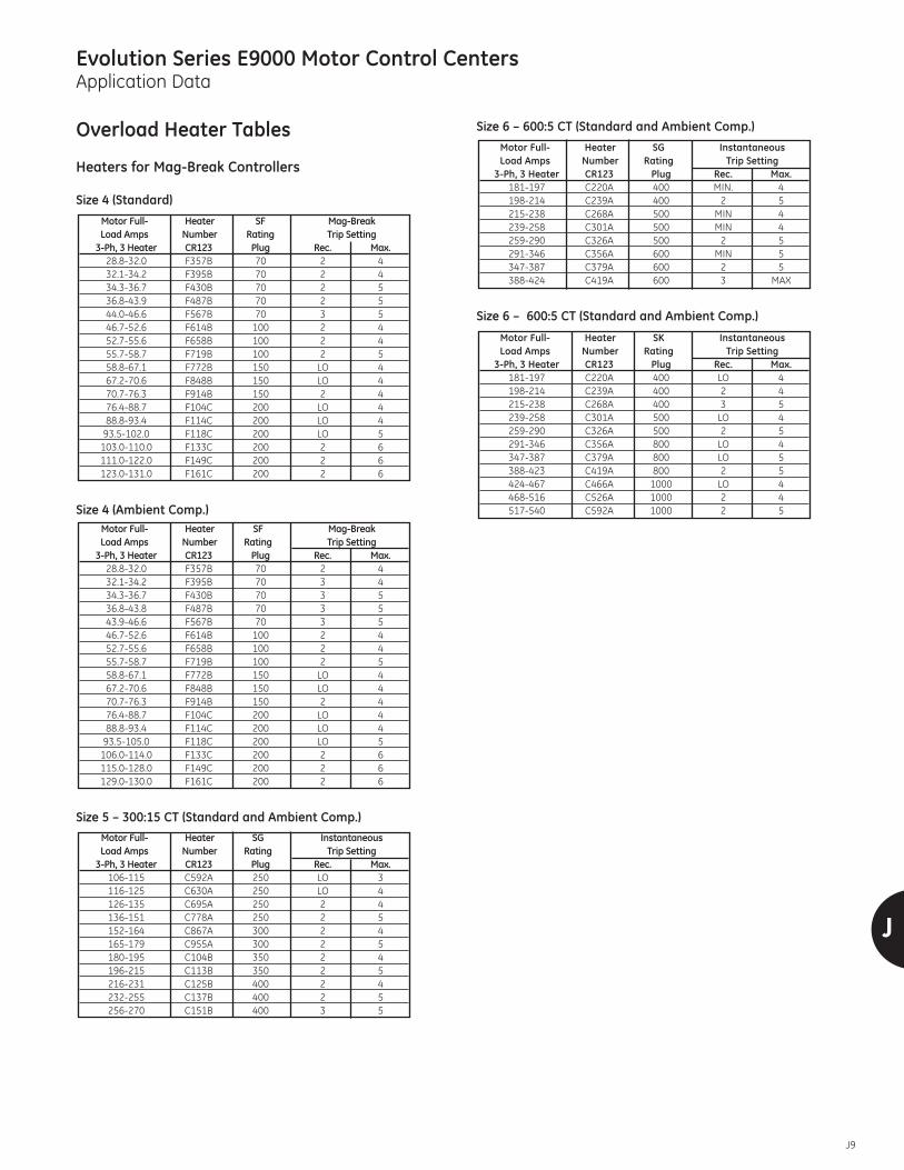
J
J9
Evolution Series E9000 Motor Control CentersApplication Data
Overload Heater Tables
Heaters for Mag-Break Controllers
Size 4 (Standard)
Size 4 (Ambient Comp.)
Size 5 – 300:15 CT (Standard and Ambient Comp.)
Size 6 – 600:5 CT (Standard and Ambient Comp.)
Size 6 – 600:5 CT (Standard and Ambient Comp.)
Motor Full- Heater SK InstantaneousLoad Amps Number Rating Trip Setting
3-Ph, 3 Heater CR123 Plug Rec. Max.181-197 C220A 400 LO 4198-214 C239A 400 2 4215-238 C268A 400 3 5239-258 C301A 500 LO 4259-290 C326A 500 2 5291-346 C356A 800 LO 4347-387 C379A 800 LO 5388-423 C419A 800 2 5424-467 C466A 1000 LO 4468-516 C526A 1000 2 4517-540 C592A 1000 2 5
Motor Full- Heater SG InstantaneousLoad Amps Number Rating Trip Setting
3-Ph, 3 Heater CR123 Plug Rec. Max.181-197 C220A 400 MIN. 4198-214 C239A 400 2 5215-238 C268A 500 MIN 4239-258 C301A 500 MIN 4259-290 C326A 500 2 5291-346 C356A 600 MIN 5347-387 C379A 600 2 5388-424 C419A 600 3 MAX
Motor Full- Heater SG InstantaneousLoad Amps Number Rating Trip Setting
3-Ph, 3 Heater CR123 Plug Rec. Max.106-115 C592A 250 LO 3116-125 C630A 250 LO 4126-135 C695A 250 2 4136-151 C778A 250 2 5152-164 C867A 300 2 4165-179 C955A 300 2 5180-195 C104B 350 2 4196-215 C113B 350 2 5216-231 C125B 400 2 4232-255 C137B 400 2 5256-270 C151B 400 3 5
Motor Full- Heater SF Mag-BreakLoad Amps Number Rating Trip Setting
3-Ph, 3 Heater CR123 Plug Rec. Max.28.8-32.0 F357B 70 2 432.1-34.2 F395B 70 3 434.3-36.7 F430B 70 3 536.8-43.8 F487B 70 3 543.9-46.6 F567B 70 3 546.7-52.6 F614B 100 2 452.7-55.6 F658B 100 2 455.7-58.7 F719B 100 2 558.8-67.1 F772B 150 LO 467.2-70.6 F848B 150 LO 470.7-76.3 F914B 150 2 476.4-88.7 F104C 200 LO 488.8-93.4 F114C 200 LO 493.5-105.0 F118C 200 LO 5106.0-114.0 F133C 200 2 6115.0-128.0 F149C 200 2 6129.0-130.0 F161C 200 2 6
Motor Full- Heater SF Mag-BreakLoad Amps Number Rating Trip Setting
3-Ph, 3 Heater CR123 Plug Rec. Max.28.8-32.0 F357B 70 2 432.1-34.2 F395B 70 2 434.3-36.7 F430B 70 2 536.8-43.9 F487B 70 2 544.0-46.6 F567B 70 3 546.7-52.6 F614B 100 2 452.7-55.6 F658B 100 2 455.7-58.7 F719B 100 2 558.8-67.1 F772B 150 LO 467.2-70.6 F848B 150 LO 470.7-76.3 F914B 150 2 476.4-88.7 F104C 200 LO 488.8-93.4 F114C 200 LO 493.5-102.0 F118C 200 LO 5103.0-110.0 F133C 200 2 6111.0-122.0 F149C 200 2 6123.0-131.0 F161C 200 2 6

J10
J
Evolution Series E9000 Motor Control CentersApplication Data
Overload Heater TablesOverload Relays
Electronic Overloads for Circuit Breaker ControllersTripping current is 120% of Dial setting. Motors with 1.15-1.25service factor, set dial to motor FLA Motors with 1.0 servicefactor, set dial to 0.9 motor FLA.
� 300:15 CT’s� 800:5 CT’s
Overload Relays for Compact 6" Starter CL45A310MJ, NEMA Size 1
FLA Range Class 10 Class 20in Amps Catalog Number Catalog Number Breaker Frame & Type0.4-.65 RTN1D E Mag. & Thermal Mag.0.65-1.1 RTN1F E Mag. & Thermal Mag.1-1.5 RTN1G E Mag. & Thermal Mag.1.3-1.9 RTN1H E Mag. & Thermal Mag.1.8-2.7 RTN1J E Mag. & Thermal Mag.2.5-4.1 RTNIK RT12K E Mag. & Thermal Mag.4.0-6.3 RTNIL RT12L E Mag. & Thermal Mag.5.5-8.5 RTNIM RT12M E Mag. & Thermal Mag.8.0-12 RTNIN RT12N E Mag. & Thermal Mag.10.0-16 RTNIP RT12P E Mag. & Thermal Mag.14.5-18 RTNIS RT12S E Mag. & Thermal Mag.17.5-22 RTNIT RT12T E Mag. & Thermal Mag.21-26 RTNIU RT12U E Mag. & Thermal Mag.
NEMA Size FLA Range in Amps Catalog Number Breaker Frame & Type1 0.8 to 1.7 CR324CXD E Mag. & Thermal Mag.1 1.8 to 3.4 CR324CXE E Mag. & Thermal Mag.1 3.2 to 6.8 CR324CXF E Mag. & Thermal Mag.1 6.5 to 13.5 CR324CXG E Mag. & Thermal Mag.1 13 to 27 CR324CXH E Mag. & Thermal Mag.2 6.5 to 13.5 CR324DXG E Mag. & Thermal Mag.2 13 to 27 CR324DXH E Mag. & Thermal Mag.2 25 to 50 CR324DXJ E Mag. & Thermal Mag.3 17 to 35 CR324FXK E Mag. & Thermal Mag.3 35 to 70 CR324FXL E Mag. & Thermal Mag.3 65 to 135 CR324FXM E Mag. & Thermal Mag.4 17 to 35 CR324FXK E,F&G Mag. & Thermal Mag.4 35 to 70 CR324FXL E,F&G Mag. & Thermal Mag.4 65 to 135 CR324FXM E,F&G Mag. & Thermal Mag.5 � 35 to 70 CR324GXN G Mag. & Thermal Mag.5 � 65 to 135 CR324GXP G Mag. & Thermal Mag.5 � 130 to 270 CR324GXQ G Mag. & Thermal Mag.6 � 130 to 270 CR324HXS G,K Mag. & Thermal Mag.6 � 260 to 540 CR324HXT K Mag. & Thermal Mag

J
J11
Evolution Series E9000 Motor Control CentersApplication Data
Overload Heater Tables
Heaters for Fused ControllersThe Mag-Break protector is factory adjusted to the minimumtrip setting.
For continuous rated motors with a service factor of 1.15 to1.25, select heaters from the heater table. For continuousrated motors with a service factor of 1.0, multiply the motorfull-load current by 0.9 and use this value to select heaters.
Overload relay tripping current in 40°C ambient is the mini-mum value of full-load current multiplied by 1.25.
Provide short-circuit protection in accordance with theNational Electrical Code, except Fuses are not to exceed thevalue shown in the table.
Suitable for use in a circuit capable of delivering not morethan the maximum RMS symmetrical amperes indicated inthe table below, 600-volts maximum, when protected by anappropriate fuse having an interrupting rating not less thanthe available short-circuit current.
Table 1–Maximum Fuse and Short-Circuit Rating
WARNING: Opening of the fuse(s) may be an indication that a fault current has been inter-rupted. To provide continued protection against fire or shock hazard, all current-carryingparts and other components of the motor controller should be examined and replaced ifdamaged. If heater burnout occurs, the complete overload relay must be replaced.
Size 0 and 1 (Standard and Ambient Comp.)
Size 2 (Standard and Ambient Comp.)
� See Table 1 for maximum fuse and short-circuit rating.
Motor Full- Heater MaximumLoad Amps Number Fuse
3-Ph., 3-Heater CR123 Rating5.48-5.85 C630A 205.86-6.47 C695A 206.48-7.35 C778A 257.36-8.06 C867A 308.07-9.03 C955A 309.04-9.61 C104B 359.62-10.5 C113B 3510.6-11.6 C125B 4011.7-12.5 C137B 4512.6-13.6 C151B 5013.7-16.7 C163B 6016.8-17.9 C180B 6018.0-18.7 C198B 70�
18.8-20.4 C214B 80�
20.5-22.7 C228B 80�
22.8-24.7 C250B 90�
24.8-26.3 C273B 90�
26.4-29.5 C303B 100�
29.6-32.5 C330B 100�
32.6-36.7 C366B 100�
36.8-41.9 C400B 100�
42.0-43.2 C440B 100�
43.3-45.0 C460B 100�
Motor Full- Heater MaximumLoad Amps Number Fuse
3-Ph., 3-Heater CR123 RatingSize 1
17.2-18.1 C198B 60�
18.2-20.0 C214B 60�
20.1-21.5 C228B 60�
21.6-22.5 C250B 60�
22.6-23.9 C273B 60�
24.0-26.3 C303B 60�
26.4-27.0 C330B 60�
Motor Full- Heater MaximumLoad Amps Number Fuse
3-Ph., 3-Heater CR123 Rating.41-.45 C054A 3.46-.49 C060A 3.50-.53 C066A 3.54-.59 C071A 3.60-.65 C078A 3.66-.76 C087A 3.77-.84 C097A 3.85-.93 C109A 3.94-1.04 C118A 31.05-1.15 C131A 31.16-1.27 C148A 31.28-1.39 C163A 31.40-1.55 C184A 61.56-1.73 C196A 61.74-1.89 C220A 61.90-2.05 C239A 62.06-2.28 C268A 62.29-2.47 C301A 62.48-2.79 C326A 102.80-3.31 C356A 103.32-3.70 C379A 123.71-4.06 C419A 154.07-4.47 C466A 154.48-4.95 C526A 154.96-5.49 C592A 205.50-5.91 C630A 205.92-6.47 C695A 256.48-7.20 C778A 257.21-8.22 C867A 308.23-8.72 C955A 308.73-9.67 C104B 35�
9.68-10.4 C113B 35�
10.5-11.0 C125B 40�
11.1-12.4 C137B 45�
12.5-13.2 C151B 50�
13.3-15.4 C163B 60�
15.5-17.1 C180B 60�
Class RK Fuse Class J Fuse Class K-1, K-5 FuseNEMA Max. Max. RMS Max. Max. RMS Max. Max. RMSSize Clip Sym. Amps Clip Sym. Amps Clip Sym. Amps1 30A 100,000 60A 100,000 Fuse 5,0002 60 100,000 100 100,000 per 5,0003 100 100,000 200 100,000 Overload 5,0004 200 100,000 400 100,000 Heater 10,0005 400 100,000 600 100,000 Table 10,000
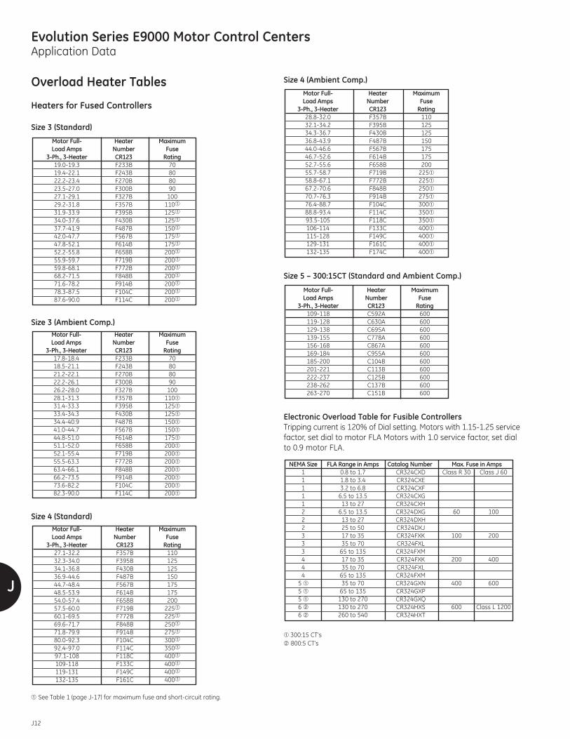
J12
J
Evolution Series E9000 Motor Control CentersApplication Data
Overload Heater Tables
Heaters for Fused Controllers
Size 3 (Standard)
Size 3 (Ambient Comp.)
Size 4 (Standard)
� See Table 1 (page J-17) for maximum fuse and short-circuit rating.
Size 4 (Ambient Comp.)
Size 5 – 300:15CT (Standard and Ambient Comp.)
Electronic Overload Table for Fusible Controllers Tripping current is 120% of Dial setting. Motors with 1.15-1.25 servicefactor, set dial to motor FLA Motors with 1.0 service factor, set dialto 0.9 motor FLA.
� 300:15 CT’s� 800:5 CT’s
NEMA Size FLA Range in Amps Catalog Number Max. Fuse in Amps1 0.8 to 1.7 CR324CXD Class R 30 Class J 601 1.8 to 3.4 CR324CXE1 3.2 to 6.8 CR324CXF1 6.5 to 13.5 CR324CXG1 13 to 27 CR324CXH2 6.5 to 13.5 CR324DXG 60 1002 13 to 27 CR324DXH2 25 to 50 CR324DXJ3 17 to 35 CR324FXK 100 2003 35 to 70 CR324FXL3 65 to 135 CR324FXM4 17 to 35 CR324FXK 200 4004 35 to 70 CR324FXL4 65 to 135 CR324FXM5 � 35 to 70 CR324GXN 400 6005 � 65 to 135 CR324GXP5 � 130 to 270 CR324GXQ6 � 130 to 270 CR324HXS 600 Class L 12006 � 260 to 540 CR324HXT
Motor Full- Heater MaximumLoad Amps Number Fuse
3-Ph., 3-Heater CR123 Rating109-118 C592A 600119-128 C630A 600129-138 C695A 600139-155 C778A 600156-168 C867A 600169-184 C955A 600185-200 C104B 600201-221 C113B 600222-237 C125B 600238-262 C137B 600263-270 C151B 600
Motor Full- Heater MaximumLoad Amps Number Fuse
3-Ph., 3-Heater CR123 Rating28.8-32.0 F357B 11032.1-34.2 F395B 12534.3-36.7 F430B 12536.8-43.9 F487B 15044.0-46.6 F567B 17546.7-52.6 F614B 17552.7-55.6 F658B 20055.7-58.7 F719B 225�
58.8-67.1 F772B 225�
67.2-70.6 F848B 250�
70.7-76.3 F914B 275�
76.4-88.7 F104C 300�
88.8-93.4 F114C 350�
93.5-105 F118C 350�
106-114 F133C 400�
115-128 F149C 400�
129-131 F161C 400�
132-135 F174C 400�
Motor Full- Heater MaximumLoad Amps Number Fuse
3-Ph., 3-Heater CR123 Rating27.1-32.2 F357B 11032.3-34.0 F395B 12534.1-36.8 F430B 12536.9-44.6 F487B 15044.7-48.4 F567B 17548.5-53.9 F614B 17554.0-57.4 F658B 20057.5-60.0 F719B 225�
60.1-69.5 F772B 225�
69.6-71.7 F848B 250�
71.8-79.9 F914B 275�
80.0-92.3 F104C 300�
92.4-97.0 F114C 350�
97.1-108 F118C 400�
109-118 F133C 400�
119-131 F149C 400�
132-135 F161C 400�
Motor Full- Heater MaximumLoad Amps Number Fuse
3-Ph., 3-Heater CR123 Rating17.8-18.4 F233B 7018.5-21.1 F243B 8021.2-22.1 F270B 8022.2-26.1 F300B 9026.2-28.0 F327B 10028.1-31.3 F357B 110�
31.4-33.3 F395B 125�
33.4-34.3 F430B 125�
34.4-40.9 F487B 150�
41.0-44.7 F567B 150�
44.8-51.0 F614B 175�
51.1-52.0 F658B 200�
52.1-55.4 F719B 200�
55.5-63.3 F772B 200�
63.4-66.1 F848B 200�
66.2-73.5 F914B 200�
73.6-82.2 F104C 200�
82.3-90.0 F114C 200�
Motor Full- Heater MaximumLoad Amps Number Fuse
3-Ph., 3-Heater CR123 Rating19.0-19.3 F233B 7019.4-22.1 F243B 8022.2-23.4 F270B 8023.5-27.0 F300B 9027.1-29.1 F327B 10029.2-31.8 F357B 110�
31.9-33.9 F395B 125�
34.0-37.6 F430B 125�
37.7-41.9 F487B 150�
42.0-47.7 F567B 175�
47.8-52.1 F614B 175�
52.2-55.8 F658B 200�
55.9-59.7 F719B 200�
59.8-68.1 F772B 200�
68.2-71.5 F848B 200�
71.6-78.2 F914B 200�
78.3-87.5 F104C 200�
87.6-90.0 F114C 200�

J
J13
Evolution Series E9000 Motor Control CentersApplication Data
Starter Fuse Selection
The following tables are furnished as a guide. Check vendorfuse characteristics before making final selection.
200 and 208 Volts
UL Class J Time-Delay RK-5Typical Switch Time Delay No Time DelayBMC CSC
Size Hp FLA Amp CSC# AJT Clip CSC# A4J Clip FRN Clip TR Clip1/2 2.3 30 3 30 10 30 2.8 30 3.5 303/4 3.2 30 5 30 10 30 4 30 4.5 301 3.9 30 6 30 15 30 5 30 6.25 30
1 1/2 5.3 30 8 30 20 30 7 30 8 301 2 7.1 30 10 30 25 30 9 30 12 30
3 10.6 30 15 30 30 30 12 30 15 305 16.3 30 25 30 45 60 20 30 25 30
7 1/2 25.3 30 30 30 60 60 30 30 30 302 10 31.3 60 50 60 90 100 40 60 40 60
15 45.1 100 60 60 110 200 60 60 60 603 20 591 100 90 100 150 200 70 100 90 100
25 731 100 100 100 175 200 90 100 100 10030 881 200 125 200 200 200 100 100 125 200440 120 200 175 200 225 400 150 200 175 20050 150 400 225 400 300 400 175 200 225 400
5 60 174 400 250 400 350 400 200 200 225 40075 210 400 300 400 450 600 250 400 300 400
BMC–Bussman FuseCSC–Chase Shawmut Fuse
230 VoltsUL Class J Time-Delay RK-5
Typical Switch Time Delay No Time Delay BMC CSCSize Hp FLA Amp CSC# AJT Clip CSC# A4J Clip FRN Clip TR Clip
1/2 2.0 30 3 30 10 30 2.5 30 3 303/4 2.8 30 4 30 15 30 3.5 30 4 301 3.4 30 6 30 15 30 4 30 5.6 30
1 1/2 4.6 30 8 30 30 30 6.25 30 8 301 2 6.2 30 10 30 25 30 8 30 10 30
3 9.2 30 15 30 30 30 12 30 15 305 14.2 30 25 30 45 60 17.5 30 25 30
7 1/2 22.0 30 30 30 60 60 25 30 30 3010 27.2 60 40 60 90 100 35 60 40 60
2 15 39.2 60 60 60 – – 50 60 60 6015 39.2 100 60 60 110 200 – – – –20 51.4 100 80 100 150 200 60 60 80 100
3 25 63.6 100 100 100 175 200 80 100 100 10030 76.6 100 100 100 200 200 100 100 100 10040 104 200 150 200 225 400 125 200 150 200
4 50 130 200 200 200 300 400 150 200 200 20060 151 400 225 400 350 400 175 200 225 400
5 75 183 400 300 400 400 400 225 400 300 400100 240 400 350 400 600 600 300 400 350 400125 296 600 450 600 600 600 350 400 450 600
6 150 348 600 500 600 – – 450 600 500 600200 468 600 – – – – 500 600 600 600

J14
J
Evolution Series E9000 Motor Control CentersApplication Data
Starter Fuse Selection
460 Volts
UL Class J Time-Delay K-5Typical Switch Time Delay No Time Delay BMC CSC
Size Hp FLA Amp CSC# AJT CLIP CSC# A4J CLIP FRS Clip TRS Clip1/2 1.0 30 1.5 30 3 30 1.25 30 1.4 303/4 1.4 30 2 30 3 30 1.6 30 2 301 1.7 30 3 30 6 30 2 30 2.5 30
11/2 2.3 30 4 30 6 30 2.8 30 4 301 2 3.1 30 5 30 10 30 3.5 30 5 30
3 4.6 30 8 30 15 30 5 30 7 305 7.1 30 10 30 25 30 9 30 10 30
7 1/2 11.0 30 15 30 35 60 15 30 15 3010 13.6 30 20 30 40 60 17.5 30 20 3015 19.6 60 30 30 50 60 25 30 30 30
2 20 25.7 60 40 60 90 100 35 60 40 6025 31.8 60 50 60 100 100 40 60 50 6030 38.3 100 60 60 110 200 45 60 60 60
3 40 52.0 100 80 100 125 200 60 60 75 10050 65.0 100 100 100 150 200 80 100 100 10060 75.5 200 110 200 175 200 90 100 110 200
4 75 91.5 200 150 200 225 400 110 200 150 200100 120 200 175 200 225 400 150 200 175 200125 148 400 225 400 300 400 200 200 225 400
5 150 172 400 250 400 350 400 225 400 250 400200 224 400 300 400 500 600 300 400 350 400250 295 600 450 600 600 600 350 400 400 400
6 300 343 600 500 600 – – 400 400 500 600350 396 600 600 600 – – 450 600 600 600400 453 600 – – – – 500 600 600 600
UL Class J Time-Delay K-5Typical Switch Time Delay No Time Delay BMC CSC
Size Hp FLA Amp CSC# AJT CLIP CSC# A4J CLIP FRS Clip TRS Clip3/4 1.1 30 2 30 3 30 1.25 30 1.6 301 1.4 30 2 30 6 30 1.6 30 2 3011⁄2 1.8 30 3 30 6 30 2.25 30 3 30
1 2 2.5 30 4 30 10 30 2.8 30 4 303 3.7 30 6 30 15 30 4.5 30 6 305 5.7 30 10 30 20 30 7 30 9 30
7 1/2 8.8 30 15 30 30 30 10 30 15 3010 10.9 30 15 30 35 60 15 30 15 3015 15.7 60 25 30 45 60 20 30 25 30
2 20 20.6 60 35 60 60 60 25 30 35 6025 25.4 60 40 60 80 100 35 60 40 6030 30.6 100 45 60 100 100 40 60 45 60
3 40 41.6 100 60 60 110 200 45 60 60 6050 52.0 100 80 100 125 200 60 60 80 10060 60.4 200 90 100 150 200 70 100 90 100
4 75 73.2 200 125 200 175 200 90 100 125 200100 96.0 200 150 200 225 400 110 200 150 200125 118 400 175 200 225 400 150 200 175 200
5 150 138 400 225 400 300 400 175 200 225 400200 179 400 300 400 400 400 225 400 300 400250 236 600 350 400 500 600 300 400 350 400
6 300 274 600 450 600 600 600 350 400 450 600350 317 600 500 600 – – 400 400 500 600400 363 600 600 600 – – 450 600 600 600
575 Volts

J
J15
Evolution Series E9000 Motor Control CentersApplication Data
Control Transformer Fusing
Control Fusing for Non-CPT Applications
Heat Loss Considerations
In determining the heat loss of a motor control center for airconditioning requirements, 250 watts per foot of lineup is areasonable assumption.
Actual heat loss will vary due to section loading and diversityfactors. A typical motor control center may operate normallyat 60 percent of maximum possible loading.
Fully rated circuit breaker starters with CPT’s, approximate losses are:
Size 1– 27 WattsSize 2– 57 WattsSize 3–130 WattsSize 4–200 WattsSize 5–300 WattsSize 6–650 Watts
Heat losses for feeders and mains vary depending on framesize, loading and type of trip with electronic trips havinglower losses. The following table provides a general guidefor estimating losses assuming 80 percent loading. For criticalapplications refer to the Company.
Typical losses for transformers:
1kVA, 1-Ph 75 Watts5 kVA, 1-Ph 190 Watts9 kVA, 3-Ph 295 Watts15 kVA, 3-Ph 460 Watts30 kVA, 3-Ph 1000 Watts
Horizontal and vertical bus losses, when loaded to capacityare approximately 100 watts per section.
Solid State Starters or VFDs will typically generate 3 wattsper ampere of load during operation.
Typical CPT Ratings (480V/120V Shown)Open CircuitVA %R %X
Secondary Volts60 9.05 1.03 131.9100 6.39 1.18 129.4150 5.02 1.01 127.3200 5.09 1.06 126.2250 6.81 .88 127.8300 5.15 .73 126.4500 5.84 1.45 128.7
600V Type ATMR or EquivalentSecondary Volts 250VType TRM or Equivalent
XFMRVA
200-230V60HZ
240V60HZ
380-400V50HZ
416V50HZ
440-480V60HZ
575-600V60HZ
110-120V50HZ
220-240V50HZ
60 1 1 3/4 6/10 1/2 1/2 6/10 3/10
75 1-1/2 1-1/2 8/10 8/10 3/4 6/10 8/10 1/2
100 2 2 1-1/4 1 1 3/4 1 6/10
150 3-1/2 3 1-1/2 1-1/2 1-1/2 1-1/4 1-6/10 8/10
200 4 4 2 2 2 1-1/2 2 1
250 5 5 2 2 2 2 2-8/10 1-1/2
300 6 6 3-1/2 3-1/2 2 2 3-2/10 1-6/10
500 6 6 6 6 5 4 5 2-8/10
Type Control Fuse Amps (Class CC)
Line to Line 10
Line to Neutral 10
Common Control 6
Separate Source 6
Type Frame Loss (Watts)SE150 15
Molded Case SF250 20Breaker Frame SG600 25
SK800 40SK1200 50800A 80
Insulated Case 1600A 210Power Break 2000A 305
2500A 375

J16
J
Evolution Series E9000 Motor Control CentersApplication Data
Motor Loads
NEMA Contactor Ratings
Non-Motor Loads
When selecting contactors for non-motor loads, the followingload characteristics should be considered:
1. Voltage and maximum continuous current.2. Maximum peak inrush current and duration.3. RMS current and duration of maximum current on cyclic loads.4. Frequency of operation.5. Maximum interrupting current, voltage, power factor andwave form.
6. Available short-circuit current.
Non-motor load ratings are based on the use of two polesto control single-phase loads and three poles to controlthree-phase loads.
Capacitor switching, requires special considerations. A dis-charged capacitor acts essentially like a short circuit, and theinrush current is limited by the impedance connected inseries with the capacitor which includes connecting cables.Therefore, the maximum capacitance which can beswitched by a contactor will increase with higher seriesimpedance. Switching more than one capacitor or capacitorbank in close electrical proximity to each other should beavoided as the energized capacitor bank can increase theinrush current to the second bank when it is energized.Reactors or resistors may be required between the twocapacitor banks to limit inrush currents.
NEMA Standards require shunt capacitors to operate satis-factorily at 135 percent of rated KVAR due to manufacturingtolerances and other variations. The higher inrush and steadystate currents associated with these capacitors should betaken into consideration.
NEMA Publication ICS2-210 covers non-motor loads.
Normal Starting Duty HP/KW rating by NEMA SizeDescription 1 2 3 4 5 6
Single Phase115V 2 3 7.5 – – –230V 3 7.5 15 – – –200V 7.5/5.5 10/7.5 25/18.5 40/30 75/55 150/110230V 7.5/5.5 15/11 30/22 50/37 100/75 200/150
Three Phase 380/415V 10/7.5 25/18.5 50/37 75/55 150/110 300/260460V 10/7.5 25/18.5 50/37 100/75 200/150 400/260575V 10/7.5 25/18.5 50/37 100/75 200/150 400/260
Maximum Transformer Primary Switching (kVA)Cont. Inrush Tung Transformers having inrush currents of not more Transformers having inrush currents of over
Size of Amps Current sten� Resistive than 20 times FLA 20 through 40 times FLAContactor (Amps Lamps Loads� Single-Phase Volts Three-Phase Volts Single-Phase Volts Three-Phase Volts
Peak) 120 240 480 600 208 240 480 600 120 240 480 600 208 240 480 6000 18 140 10 18 0.6 1.2 2.4 3 1.8 2.1 4.2 5.2 0.3 0.6 1.2 1.5 0.9 1.0 2.1 2.61 27 288 15 27 1.2 2.4 4.9 6.2 3.6 4.3 8.5 11 0.6 1.2 2.5 3.1 1.8 2.1 4.3 5.32 45 483 30 45 2.1 4.1 8.3 10 6.3 7.2 14 18 1.0 2.1 4.2 5.2 3.1 3.6 7.2 8.93 90 947 60 90 4.1 8.1 16 20 12 14 28 35 2.0 4.1 8.1 10 6.1 7.0 14 184 135 1581 120 135 6.8 14 27 34 20 23 47 59 3.4 6.8 14 17 10 12 23 295 270 3163 240 270 14 27 54 68 41 47 94 117 6.8 14 27 34 20 24 47 596 540 6326 480 540 27 54 108 135 81 94 188 234 14 27 54 68 41 47 94 117
NEMA Contactor Ratings
� 300-volts maximum, Tungsten lamp loads include infrared lamps having Tungstenfilaments.
� Resistive loads include electric discharge lamps such as fluorescent, mercury, vapor, etc.

J
J17
Evolution Series E9000 Motor Control CentersApplication Data
Non-Motor Loads
NEMA Contactor Ratings for Single Capacitor or Capacitor Bank Switching
Disconnect minimums: thermal magnetic breakers rated 135%, fused switch rated 165%.
NEMA Contactor for Heating Loads
Application of Starters for Heating and Lighting Loads1. No Tungsten lamp loads, No transformer loads.2. Contactor loading must meet table above.3. Overload heaters may be sized for maximum�.4. Disconnect must be thermal magnetic or fused switch rated per NEC @ 125% of load amps.
� Available at capacitor terminals.� Applicable only to resistive loads having inrush currents not exceeding 1.5 times the continuous current rating.
� Spectra CB will permit deletion of overload heaters for these loads.
Continuous Maximum kW Ratings�NEMA Current 575 Volts 460 Volts 230 Volts 115 VoltsSize Rating 2-Pole 3-Pole 2-Pole 3-Pole 2-Pole 3-Pole 2-Pole 3-Pole
Amps 1-Ph 3-Ph 1-Ph 3-Ph 1-Ph 3-Ph 1-Ph 3-Ph00 9 5 9 4 7 2 3.5 1 1.750 18 10 18 8 14 4 7 2 3.51 27 15 25 12 20 6 10 3 52 45 25 43 20 34 10 17 5 8.53 90 50 86 40 68 20 34 10 174 135 75 130 60 105 30 52 15 265 270 150 260 120 210 60 105 30 526 540 300 515 240 415 120 210 60 1057 810 450 775 360 625 180 315 90 1558 1215 700 1200 540 960 270 480 135 2409 2250 1290 2200 1020 1740 510 880 255 440
Size of Continuous Three-Phase Rating of CapacitorController Ratings RMS Maximum Size of Three-Phase Capacitor in kVAR or Available Current� in Amperes RMS Sym.
Amperes 3000 5000 10,000 14,000 18,000 22,000At 230 Volts, 60 Hertz
2 45 12 8 4 3 2 23 90 27 27 15 11 9 74 135 40 40 40 30 24 205 270 80 80 80 80 80 756 540 160 160 160 160 160 160
At 460 Volts, 60 Hertz2 45 25 16 8 6 4 43 90 53 53 31 23 18 154 135 80 80 80 61 49 415 270 160 160 160 160 160 1496 540 320 320 320 320 320 320
At 575 Volts, 60 Hertz2 45 31 20 10 7 6 53 90 67 67 39 29 23 194 135 100 100 100 77 61 515 270 200 200 200 200 200 1896 540 400 400 400 400 400 400

J18
J
Evolution Series E9000 Motor Control CentersApplication Data
Non-Motor Loads
Application Rated
Maximum kVA of Transformer for Primary Switching (50/60Hz)a
Maximum Three-Phase kVAR Rating for Switching CapacitorsCatalog 10,000 Amps RMS 22,000 Amp RMSNumber Maximum Available Fault Current Maximum Available Fault Current
200V 230V 460V 575V 200V 230V 460V 575VCL00 3 3 5 5.7 1.5 1.5 2.5 2.8CL01 435 4.5 9.5 11 2.2 2.2 4.5 5.5CL02 6.5 6.5 11 12.5 3.2 3.2 5.5 6.2CL25 9 9 15 17.5 4.5 4.5 7.5 8.2CL04 12.5 12.5 21 24 6.2 6.2 10.5 12CL45 17 17 30 35 8.5 8.5 15 17.5CL06 22 22 40 50 11 11 20 25CL07 25 25 45 65 12.5 12.5 22.5 32.5CL08 30 30 50 70 15 15 25 35CL09 40 40 65 95 20 20 32.5 47.5CL10 50 50 80 120 25 25 40 60CK75 60 60 100 150 60 60 100 150CK08 70 70 130 175 70 70 130 175CK09 95 95 165 230 95 95 165 230CK95 105 105 190 288 105 105 190 288CL10 135 135 260 370 135 135 260 370CL11 190 190 325 450 190 190 325 450CK12 250 250 400 600 250 250 400 600
Catalog Max. Peak Inrush = 20 x Normal Inrush = 40 x NormalNumber Closing Current Phase 120V 208V 240V 480V 600V 120V 208V 240V 480V 600VCL00 450 Amps 1 0.6 1 1.2 1.7 2.1 0.3 0.5 0.6 0.8 1
3 1.1 1.9 2.2 3.1 3.8 0.5 0.9 1.1 1.5 1.9CL01 450 Amps 1 0.8 1.4 1.7 2.4 3.0 0.4 0.7 0.8 1.2 1.5
3 1.5 2.6 3.0 4.2 5.2 0.7 1.3 1.5 2.1 2.6CL02 450 Amps 1 1.2 2.0 2.5 3.5 4.4 0.6 1.0 1.2 1.7 2.2
3 2.2 3.8 4.5 6.3 7.7 1.1 1.9 2.2 3.1 3.8CL25 550 Amps 1 1.8 3.1 3.7 5.2 6.4 0.9 1.5 1.8 2.6 3.2
3 3.2 5.5 6.5 9.1 11.2 1.6 2.7 3.2 4.5 5.6CL04 550 Amps 1 2.2 3.8 4.5 6.3 7.8 1.1 1.9 2.2 3.1 3.9
3 4.0 7.0 8.0 11.2 13.7 2.0 3.5 4.0 5.6 6.8CL45 550 Amps 1 2.8 4.8 5.7 8.0 9.7 1.4 2.4 2.8 4.0 4.8
3 5 8.6 10 14.0 17 2.5 4.3 5 7.0 8.5CL06 1000 Amps 1 3.4 5.9 6.8 9.5 12 1.7 2.9 3.4 4.7 6
3 6 10.4 12 16.8 21 3 5.2 6 8.4 10.5CL07 1000 Amps 1 4.2 7.2 8.5 12 14.2 2.1 3.6 4.2 6.0 7.1
3 7.5 13 15 21 25 3.7 6.5 7.5 10.5 12.5CL08 1000 Amps 1 5.7 10 11.4 16 20 2.8 5.0 5.7 8.0 10
3 10 17.3 20 28 35 5 8.6 10 14 16CL09 1280 Amps 1 7.1 12.3 14.2 20 22.8 3.5 6.1 7.1 10 11.4
3 12.5 21.6 25 35 40 6.2 10.8 12.5 17.5 20CL10 1280 Amps 1 8.5 14.7 17.1 24 28.5 4.2 7.3 8.5 12 14.2
3 15 26 30 42 50 7.5 13 15 21 25CK75 1850 Amps 1 10 17.2 20 28 31.3 5 8.6 10 14 15.6
3 17.5 30.3 35 49 55 8.75 15.1 17.5 24.5 27.5CK08 1850 Amps 1 11.4 19.7 22.8 32 34.2 5.7 9.8 11.4 16 17.1
3 20 34.6 40 56 60 10 17.3 20 28 30CK09 2500 Amps 1 14.2 24.6 28.5 40 48.5 7.1 12.3 14.2 20 24.2
3 25 43.3 50 70 85 12.5 21.6 25 35 42.5CK95 3700 Amps 1 18.5 32.0 37.1 52 62.8 9.2 16.0 18.5 26 31.4
3 32 55.4 65 91 110 16 27.7 32 45 55CK10 7000 Amps 1 22.8 39.5 45.7 64 85.7 11.4 19.7 22.8 32 42.8
3 40 69.3 80 112 150 20 34.6 40 56 75CK11 7000 Amps 1 28.5 49.4 57.1 80 97.1 14.2 24.7 28.5 40 48.5
3 50 86.6 100 140 170 25 43.3 50 70 85CK12 8400 Amps 1 45.7 79.2 91.4 128 160 22.8 39.6 45.7 64 80
3 80 138.6 160 224 280 40 69.3 80 112 140

J
J19
Evolution Series E9000 Motor Control CentersApplication Data
Non-Motor Loads
Application Rated
Utilization in Category AC-1, General Use
Horsepower/kilowatt ratings are shown belowCatalog General Purpose 1 Phase-HP A 3 Phase-HP A Power InNumber Ratings Max. FLA 115V 230V 200V 230V 460V 575V 380/400V kW ACL00 25 10 .5 (9.8) 1.5 (10) 3 (11) 3 (9.6) 5 (7.6) 7.5 (9) 4 (9)CL01 25 13.8 .75 (13.8) 2 (12) 3 (11) 3 (9.6) 7.5 (11) 10 (11) 5.5 (12)CL02 32 17.5 1 (16) 3 (17) 5 (17.5) 5 (15.2) 10 (14) !5 (17) 7.5 (18)CL25 32 22,22,17� 1.5 (20) 3 (17) 5 (17.5) 7.5 (22) 15. (21) 15 (17) 11 (25)CL04 54 32A 2 (24) 5 (28) 10 (32) 10 (28) 20 (27) 25 (27) 16 (32)CL45 55 34,34,27� 3 (34) 5 (28) 10 (32) 10 (28) 25 (34) 25 (27) 18.5 (40)CL06 80 48 3 (34) 7.5 (40) 15 (48) 15 (42) 30 (40) 40 (41) 22 (50)CL07 100 62 5 (56) 10 (50) 20 (62) 20 (54) 40 (52) 50 (52) 30 (65)CL08 110(O) 102 (E) 68 5 (56) 15 (68) 20 (62) 25 (68) 50 (65) 60 (62) 37 (80)CL09 140 (O) 120 (E) 80 7.5 (80) 15 (68) 25 (78) 30 (80) 60 (77) 75 (77) 45 (95)CL10 140 (O) 120 (E) 104,96,80� 10 (100) 20 (88) 30 (92) 40 (104) 75 (96) 75 (77) 55 (105) CK75 150 140 10 (100) 25 (110) 40 (120) 50 (130) 100 (124) 125 (125) 75 (154)CK08 175 156 15 (135) 30 (136) 50 (149.5) 60 (145) 125 (156) 125 (125) 90 (185)CK09 200 192 – – 60 (169.4) 75 (192) 150 (180) 150 (144) 132 (250)CK95 310 302 – – 100 (285) 100 (248) 250 (302) 300 (289) 160 (310)CK10 500 398 – – 125 (358) 150 (360) 300 (361) 400 (382) 220 (420)CK11 600 480 – – 150 (414) 200 (480) 400 (477) 500 (472) 280 (550)CK12 650(E) 750 (O) 602 – – 200 (552) 250 (602) 500 (590) 600 (574) 375 (700)
4-pole ContactorsCL Contactors CK Contactors
01 02 03 04 06 07 08 09 08 09 95 10 11 12Max. operational current 40°C A 25 32 40 54 70 100 110 120 175 200 310 500 550 650at ambient temperature 55°C A 25 32 40 54 70 100 110 120 175 200 310 425 462 543of: (for all voltages) 70°C A 20 25 28 41 52 78 88 80 155 175 270 335 462 468
3-pole ContactorsCL Contactors CK Contactors
00 01 02 25 04 45 06 07 08 09 10 75 08 09 95 10 11 12Max. operational current 40°C A 25 25 32 32 54 55 80 100 102 120 120 150 175 200 310 500 600 650at ambient temperature 55°C A 25 25 32 32 54 55 80 100 102 120 120 150 175 200 310 425 510 546of: (for all voltages) 70°C A 20 20 25 25 41 44 62 78 81 80 80 130 155 175 270 335 432 468

J20
J
Evolution Series E9000 Motor Control CentersApplication Data
Publication References
Construction Equipment and Components
Factory Automation Products
Motor Control Center Equipment
� For more information visit our website at www.gefanuc.com/default2.htm
Publication Description Stocking LocationSpectra Series and 8000-Line MCCDEA-036 Spectra Series Product Brochure BloomingtonGEF-4628 8000-Line Renewal Parts Bulletin BloomingtonGEH-4961 Installation and Maintenance (Instructions) Bloomington
Publication� Description Stocking LocationGE Fanuc Programmable Logic ControlGFW-0067 Automation Solutions Catalog CharlottesvilleGE Fanuc I/OGEK-90486 Genius I/O System User’s Manual CharlottesvilleGFA-089 Genius I/O System CharlottesvilleGEI-86150 Installation and Operation Instructions BloomingtonGFA-150 Field Control™ CharlottesvilleGFT-298 VersaMax I/O CharlottesvilleGFA-180 VersaMax Charlottesville
Publication Description Stocking LocationGEP-1100 Buylog Catalog–Covers Full Line of Products BloomingtonMolded Case Circuit BreakersGET-2779 Application and Selection Guide for Molded Case Circuit Breakers BloomingtonGEZ-7000 MCCB Time-Current Curves BloomingtonGET-7002 Spectra RMS Molded Case Circuit Breakers BloomingtonPower Break Insulated Case Circuit BreakersGET-6211 Selection and Application BloomingtonGEZ-7001 Time-Current Curves BloomingtonLow Voltage Power Circuit BreakersGEI-86150 Installation and Operation Instructions BloomingtonGEK-7310 Maintenance Manual BloomingtonGEZ-7002 Type AKR Time-Current Curves BloomingtonGES-6227 Type AKR MicroVersaTrip RMS-9 Time Current Curves BloomingtonGES-6228 MicroVersaTrip Ground Fault Time-Current Curves BloomingtonDisconnect SwitchesGET-6205 Type HPC High-Pressure Contact Switches, Technical BloomingtonGEZ-7003 Type HPC Time-Current Curves BloomingtonGround Fault Protective ProductsGET-2964 Ground Break Systems BloomingtonGEZ-7003 Ground Break Time-Current Curves BloomingtonPanelboardsGET-6592 “A” series Tech. Specifications BloomingtonGEA-11316 A Series Bloomington

J
J21
Evolution Series E9000 Motor Control CentersApplication Data
Publication References
General Purpose Controls
Web Access� G11/P11 Drives — www.ge.com/industrialsystem/drives/catalog/af300g11/index.htm
Publication Description Stocking LocationGEP-1260 Control Catalog–Covers Full Line of Products BloomingtonMagnetic Motor StartersGEA-10928 300-Line Magnetic Motor Starters, Descriptive BloomingtonGEH-5190 300-Line Instructions, Nema Size 1, FVNR BloomingtonGEH-4774 300-Line Instructions, Nema Size 2, FVNR BloomingtonGEH-4806 300-Line Instructions, Nema Size 3, FVNR BloomingtonGEH-4807 300-Line Instructions, Nema Size 4, FVNR BloomingtonGEH-4869 300-Line Instructions, Nema Size 5, FVNR BloomingtonGEH-5198 300-Line Instructions, Nema Size 6, FVNR BloomingtonGEH-5190 300-Line Instructions, Nema Size 1, FVR and 2-Speed BloomingtonGEH-4775 300-Line Instructions, Nema Size 2, FVR and 2-Speed BloomingtonGEH-4806 300-Line Instructions, Nema Size 3, FVR and 2-Speed BloomingtonGEH-4807 300-Line Instructions, Nema Size 4, FVR and 2-Speed BloomingtonGEH-4839 300-Line Instructions, Nema Size 5, FVR and 2-Speed BloomingtonPilot DevicesGEA-10877 CR104P Push-buttons and Pilot Lights BloomingtonRelays and TimersGEA-10639 CR122B, CR122BT, Series A Relays BloomingtonGEH-4115 CR120B AC Relays BloomingtonGEH-4120 CR120B Latched Relays BloomingtonGEH-4147 CR122B Time-Delay Relays BloomingtonGEH-4139 CR122BP Time-Delay Relays BloomingtonGEH-6435 Spectra ECM Instructions BloomingtonDET-069 Spectra ECM Product Brochure BloomingtonVariable Speed Drives�GEI-100364 AF 300P User Guide Fort WayneGEI-100363 AF 300G User Guide Fort WayneSolid State StartersDEH-40397 ASTAT–CD Plus User Manual BloomingtonGEH-6533 ASTAT–CD Plus Instructions BloomingtonDEH-40396 ASTAT–IBP Plus User Manual BloomingtonDEH-40417 ASTAT–IBP Plus Instructions Bloomington

J22
J
Evolution Series E9000 Motor Control CentersApplication Data
Electrical Data
Motor horsepower output may also be calculated as follows:
HP = V x A x Pf x EFF746
Rules of Thumb (Approximation)At 1800 RPM, a motor develops a 3 lb. – ft. per HP.At 1200 RPM, a motor develops 4.5 lb – ft. per HP.At 460 volts, a 3-phase motor draws 1.25 amp per HP.At 230 volts, a 3-phase motor draws 2.5 amp per HP.
Conversion Formulas
Values Ohms LawV=Volts I=E/RA or I = Amperes (amps) R=E/IWork/P = Watts/Power E=IXRKW=Kilowatts P=IXEKwH=Kilowatt Hours P=IXIXRKVA=Kilovolt AmperesPf=Power Factor, TablePh= Phase Factor, Table
kVAR Calculation When Motor OperatingCharacteristics Are KnownIf motor HP, full-load power factor (PF) and efficiency (eff)are known, its easy to calculate the correct kVAR necessaryto improve PF to any value.
Example: 75HP, 3600 RPN, NEMA B motor with full-load PF of 87% and eff. of 92% cor-rected to 95%PF
Original PF = .87 Cos: Tan: = .567Desired PF = .95 = Cos: Tan: = .329Difference = .238
KW = HPx.746 or 75x.746 = 62Eff. .902
.238 X 62 = 14.8 kVAR (use 15 kVAR)
Defining the Load
Rotating Motion Linear Motion
HorsepowerHP = T x N HP = F x V
5250 33,000
Where: T = Torque (lb-ft) Where: F = Force or Tension (lb)N = Speed (RPM) V = Velocity (FPM)
HP = T x N HP = F x V63,000 396,000
Where: T = Torque (lb-in) Where: F = Force or Tension (lb)N = Speed (RPM) V = Velocity (in/min)
Accelerating Torque/ForceTA = WK2 x N FA = W x V
308t 1933t
Where: TA = Accelerating torque Where: FA = Accelerating Force(lb ft) (lb-ft)
WK2 = Total system inertia W = Weight (lb)that must be accelerated. V = Change in velocity (FPM)This includes motor rotor, t = Time (sec.)speed reducer (if used),and load. (lb-ft2)
TorqueT = F x R
Where: T = Torque (lb-ft)F = Force (lb)R = Radius (ft)
WK2 – reflected
Reflected WK2 = WK2 of Load(Reduction Ratio)2
This is for either belt or gear reductions.
FPM to RPMRPM = FPM
.262 x (diameter in inches)
To find Alternating Current Three-PhaseAmperes when HP x 746Horsepower is known 1.73 x V x Eff x fpAmperes when Kw x 1000Kilowatts is known 1.73 x V x pfAmperes when Kva x 1000Kva is known 1.73 x VKilowatts 1.73 x A x V x pf
1000Kva 1.73 x A x V
1000Horsepower - 1.73 x A x V x Eff x pf(Output) 746KW (alternating current) = KVA x Power FactorKW (direct current) = V x A x .001KWH = KW x HoursHP = KW
Motor Efficiency

J
J23
Evolution Series E9000 Motor Control CentersApplication Data
Electrical Data
Centrifugal Loads
Flow Rate: Flow1 = RPM1Flow2 = RPM2
Torque: Torque1 = RPM1 2Torque2 = RPM2
Pressure: Pres1 = RPM1 2Pres2 = RPM2
Horsepower: BHP1 = RPM1 3BHP2 = RPM22
Fans & Blowers: BHP = CFM x PSF3300 x (fan efficiency)
BH = CFM x PIW 6350 x (fan efficiency)
BHP = CFM x PSI229 x (fan efficiency)
Pumps: BHP = GPM x TH x (specific gravity)3960 x (pump efficiency)
BHP = GPM x PSI x (specific gravity)1713 x (pump efficiency)
Where: BHP = Brake horsepowerPSF = Pounds per square footPIW = Pressure in inches of water guagePSI = Pounds per square inchGPM = Gallons per minuteTH = Total head (including friction)
Other Useful Formulas
Gear Ratio - Most Favorable
GR = WK2 + Tf2 + TfWKM2 TM2 TM
Where: WK2 = WK2 of the loadWK2M = WK2 of the motorTf = Friction torque of the laodTM = Average motor torque during acceleration
If friction torque is low compared to accelerating torque this canbe reduced to:
GR = WK2
WK2
Duty Cycle Calculations
HP = HP21t + HP22t + HP3t2 + etcRMS t1 + t2 + t3 + etc

K
K1
Evolution Series E9000 Motor Control CentersDrawings/Tests
E9000 MCC Unit Numbering System
The General Electric Engineering Documentation System willaccept a 3-character unit address designation consisting ofa combination of letters and/or numbers (such as: 12J, ABC,A1D, 2AD, etc.). The recommended unit addressing system isillustrated and described in the following paragraphs.
Note: Should customer’s (3-character maximum) unit numbering system differ fromthe following GE unit addressing system, then both can appear when requested on theCAD-generated motor control center unit summary drawings issued from the factory.
BenefitsWhen ordering NEMA Class I or II motor control centers wherefactory interconnections are required, this system producesa uniform numbering format for engineering documentation.The GE unit numbering system produces a unique unit addressdesignation. When wiremarkers are specified, it ensuresconsistency and ease of wire tracing/troubleshooting betweenfactory-wired units and other devices within the motor controlcenter lineup such as programmable control I/O racks.
GeneralTypical 3-Character Designation 1 A D
Motor Control Center number/characterVertical Section number/characterUnit Location (line number/character)
Note: The motor control center number/character assignment may be a number (1, 2,3, 4, etc.) provided the number of MCC lineups on an order does not exceed 9. If 10 orgreater, then the motor control center character should be a letter of the alphabet (A,B, C, D, etc.). Likewise, the vertical section character should be an alphabetic entry forlineups exceeding 9 sections.
The outline summary drawing furnished with the equipmentcross-references the unit location and the service designationspecified for each unit.
Motor Control Center No. 1
Front View
Number the front view arrangement from left-to-right 1, 2, 3 …or A, B, C … Line off the space required for the top and bottomhorizontal wireways. Then line off the interconnecting verticalwireway in each vertical section. Note that some units(including large starters, transformers, panelboards, etc.) mayrequire full width of section and that no separate verticalwireway door will be adjacent to these units.
Example:Assume that the top horizontal wireway is to be 12 incheshigh. In the first section a full-voltage non-reversing NEMASize 1 combination starter is to be installed in the first availableposition below the top horizontal wireway. Assuming conventional unit sizing (FVNR-1 equals 1X or 12-inch unitheight), the unit location assignment becomes:
1 A D
Motor Control CenterVertical SectionUnit Location
Continue lining off the unit space requirements for variousunits and future spaces as required until the lineup is com-plete and all spaces have been addressed. Notice that everyunit location has a unique unit location designation. Thisunit designation will not be repeated again within the order.Since every motor control center lineup also has a uniquepanel catalog number, then the unit nameplate and catalognumber will never be duplicated.
Example: ML # 0447X0542L01 – 1AD
MCC Cat NumberUnit Location
A reminder about future spaces: If a 2X future space is to bearranged into two 1X compartments, then the outline sketchmust be lined off into 1X compartments with individual unitaddresses. This will ensure that the necessary unit doorsand shelves will be provided by the factory.A B C D
A
B
C
D
E
F
G
H
I
J
K
L
M
N
O
1AD

K2
K
Evolution Series E9000 Motor Control CentersDrawings/Tests
E9000 MCC Unit Numbering System
Mebane CAD documentation system permits the engineerto perform virtually all design functions without the need oftraditional drafting tools and associated equipment. Thiscomputer-based system is used to translate equipmentfunctional requirements into detailed equipment designsand material lists. These computerized drawings are used inthe manufacturing process to increase product assemblyaccuracy, repeatability and consistency. Standardization ofproduction procedures and methods has been improvedsuch that given devices are consistently located in the sameposition on or within the equipment. Unit wiring is handledin the same manner, resulting in improved wiring accuracyand productivity.
The following drawing elements are included in the standarddocumentation package. Customer will receive A-size (81/2 x 11 inches) prints.
1) Lead Sheet Fig. 12) Outline Fig. 23) Summary Tables Fig. 34) Unit Elementaries Section K
1. Lead Sheet – Contains special Customer notes and manu-facturing or test instructions.
2. Outline – Presents front view plan drawings showing thephysical arrangement of units and associated equipmentwithin the motor control center lineup.
3. Summary Tables – Provides all necessary functional detailof each unit including nameplate inscriptions.
Fig. 1

K
K3
Evolution Series E9000 Motor Control CentersDrawings/Tests
E9000 MCC Unit Numbering System
Fig. 2
Fig. 3
UNIT SUMMARY EVOLUTION SERIES MCCREQ. NO.PANEL CAT. NO.FRONT
ENG. NAME JBCISSUED 01/16/1996 REV.REV NO. 0
DWG. FOR INSTALLATAION DWG. NO. SH F01ACONT. ON SH F01B
UNIT
LOC
UNIT
MOD
SH
CUST
UNIT
NO
AAD
AAF
AAH
AAJ
AAL
AAN
ABD
ABF
ABH
ABJ
6-MILLFEED END
JACKING PUMP
RED RUN PTT LT
100 200A FVNR 1 1 1.8 1000 1.150 C220A AMBIENT SELI 3 3 0 UL 157 150 IA52-102437
6-MILLFEED END
JACKING PUMP
RED RUN PTT LT
100 200A FVNR 1 1.5 2.4 1000 1.150 C301A AMBIENT SELI 3 3 0 UL 157 150 IA52-102438
6-MILLFEED END
FILTRATION PUMP
RED RUN PTT LT
100 200A FVNR 1 1.5 2.4 1000 1.150 C301A AMBIENT SELI 3 3 0 UL 157 150 IA52-102438
6-MILLDISCHARGE ENDJACKING PUMP
RED RUN PTT LT
100 200A FVNR 1 1.5 2.4 1000 1.150 C301A AMBIENT SELI 3 3 0 UL 157 150 IA52-102438
6-MILLDISCHARGE ENDEXT. LUBE PUMP
RED RUN PTT LT
100 200A FVNR 1 1.5 2.4 1000 1.150 C301A AMBIENT SELI 3 3 0 UL 157 150 IA52-102439
6-MILLDISCHARGE END
FILTRATION PUMP
RED RUN PTT LT
100 200A FVNR 1 1.5 2.4 1000 1.150 C301A AMBIENT SELI 3 3 0 UL 157 150 IA52-102439
7-MILLFEED END
JACKING PUMP
RED RUN PTT LT
100 200A FVNR 1 1.5 2.4 1000 1.150 C301A AMBIENT SELI 3 3 0 UL 157 150 IA52-102438
7-MILLFEED END
EXT. LUBE PUMP
RED RUN PTT LT
100 200A FVNR 1 1.5 2.4 1000 1.150 C301A AMBIENT SELI 3 3 0 UL 157 150 IA52-102438
7-MILLFEED END
FILTRATION PUMP
RED RUN PTT LT
100 200A FVNR 1 1.5 2.4 1000 1.150 C301A AMBIENT SELI 3 3 0 UL 157 150 IA52-102438
7-MILLDISCHARGE ENDJACKING PUMP
RED RUN PTT LT
100 200A FVNR 1 1 1.8 1000 1.150 C220A AMBIENT SELI 3 3 0 UL 157 150 IA52-102437
CAT# 273A7916P3FC
NAMEPLATEELEM CONN.
DRWSIZE
FUNCTIONSIZE
HPKWK-KW
FLA RPM SFOLHEATERCR123
OLRELAYTYPE
CBSW
TRIP FUSE/CLIP
FUSESBY
0 0
TOTALAUXINILK UL
LABELCSALABEL
NOT LABELED
SCMARKER
CPTVA
CATALOGNUMBER
GE ENERGYMEBANE, NC USA
FRONTVIEW
SECT. HEIGHT 90 INCHES
UL SECT. NO.X=SHIPPING LENGTH>=SPLICE
MOD SHEETSECT. WXDVERT. BUS A
UL UL UL UL
300
1
FRONT 20X20
300
2
FRONT 20X20
300
3
FRONT 20X20
600/300
4
FRONT 20X20
001 002
FVNR1
AADFVNR
1.5
AAF
FVNR1.5
AAH
FVNR1.5
AAJ
FVNR1.5
AALFVNR
1.5
AAN
FVNR1.5
ABDFVNR
1.5
ABF
FVNR1.5
ABH
FVNR1
ABJ
FVNR1
ABLFVNR
1
ABN
> < INCLINE600
ADCSPACEADD
SPACE
ADF
SPACE
ADH
FDRCB/ADI
FDRCB/ADJ
SPACE
ADL
SPACE
ADN
FDRCB/ACC
FDRCB/ACD
FDRCB/ACE
FDRCB/ACF
FDRCB/ACG
FDRCB/ACH
FDRCB/ACI
FDRCB/ACJ
FDRCB/ACK
FDRCB/ACL
FDRCB/ACM
FDRCB/ACN

K4
K
Evolution Series E9000 Motor Control CentersDrawings/Tests
Paint Finish
Indoor EquipmentThe standard Mebane paint system consists of the followingtwo processes.
Phase I–CleaningIn a 7-stage spray washer, steel parts are cleaned andsprayed in the controlled cleaning solutions.
Cleaned steel parts enter a drying oven at 300-350°F. Thepreceding operating parameters have been determined toproduce an Iron Phosphate coating of a minimum of 150milligrams per square foot to meet MIL Spec. TT-C-490.
Phase II–Painting by Electro-static Powder ProcessPrimed metal parts are electrostatically coated with a powderpaint consisting of the following:
670-011 ANSI-61 Polyester Paint (Light Gray)
Metal parts will enter drying oven at 375-400°F and remainfor 20 minutes. The standard color is ANSI-61 light gray witha gloss of 60±5, and a thickness of 1.5 mils. This system willwithstand a minimum of 1000 hour humidity test, plus 600hours salt spray test.
Packaging and Storage
Domestic PackagingNormally a motor control center Lineup is shipped in groupsof three vertical sections for ease of handling. Each shippingsplit is mounted on a hardwood skid to facilitate moving byrollers or fork-lift truck. Lifting eyes are also provided formoving by crane. Shipping blocks are placed on the face ofthe sections to protect handles and devices. The shippingsplits are wrapped in clear stretch polyfilm to protect theequipment from the usual dust and dirt encountered duringshipment. Necessary bus splice bars are included for connectingthe shipping splits together.
Export CratingThe sections are bolted to a skid with a solid floor. Theequipment is then enclosed in a 3/8" plywood crate with 2 x 4reinforcing at the top and corners. Three 1 1/4" steel bands areplaced horizontally around the crate for additional reinforcing.
All equipment should be protected against moisture andtemperature extremes during shipment and storage. SeeEnvironmental Considerations in Section A (General). Forprolonged shipping periods where export crating is involved,it is recommended the equipment space heaters (whenspecified) be wired for connecting to an external power sourcewhile in transit, to minimize condensation.
StorageIf it is necessary to store the equipment for any length oftime, the following precautions should be taken:
1. Uncrate equipment.2. Store in a clean, dry area at moderate temperature. Coverwith a suitable canvas or heavy-duty plastic cover to prevententrance of foreign material.
3. If equipment must be stored in cool or damp areas, notonly should the equipment be completely covered, but heatshould be provided to prevent condensation of moisturein the equipment. Energize space heaters (if furnished inthe equipment) or place a standard 120-volt lamp rated75 watts inside the bottom of each vertical section.
Stage Temperature Chemical Solution(s)1–Cleaning 115-120° Ferro Clean GE2–Rinse 105-118° None3–Iron Phosphate 90-105° Secure Low Foam4–Rinse Ambient None5–Non Chrome Sealer Ambient Non Chrome Final Seal6–Rinse Ambient None7–Deionized Rinse Ambient None

K
K5
Evolution Series E9000 Motor Control CentersDrawings/Tests
Standard Commercial Tests and Inspection
GeneralThe following summary description defines the standardfactory tests and inspections performed during manufacture.All GE motor control center equipment is tested and inspectedfor conformance with NEMA ICS 18-2001. Production tests andinspections encompass the verification of physical configurationof assembly and workmanship, the mechanical adjustmentsof parts and components, and the sequencing and functionaloperations of the control systems. These tests and inspectionsare performed on manufactured products to verify conformanceof the equipment to a previously qualified design. The testsdo not include type testing or other destructive tests onequipment to be shipped to a customer. Any additional factorytests beyond those listed in the following paragraphs must bereferred to Mebane to verify availability of test facilities andqualified manpower. Additional testing beyond the scope ofthe following standard commercial tests will affect normalshipment schedules.
Production TestsThe following list of inspection activities shall be performed toassure proper and correct materials, workmanship and for anydamage conditions in accordance with the manufacturingdocumentation and drawings:
• Components, parts and material• Physical condition of components, parts, wire insulation• Location and orientation of components and parts• Finish–plating–painting• Wire/cable type, size, insulating and clamping support• Wire terminations, insulation removal and crimping of terminals
• Tightness of electrical connections and torque of bus bar bolts• Wire markers and terminal markers (where specified)• Labeling of components, parts, etc.• Tightness torque of assembly bolts and hardware• Welds (spot only)• Mechanical clearance• Electrical clearance (potential hazards)
Mechanical Operations TestMechanical operating tests shall be performed to insure properfunctioning of operating mechanisms and interchangeability.
a. The operation of shutters, mechanical interlocks, circuit-breaker-door interlocks, operating handles, trip mechanisms,solenoid armature travels, contact wipes, electromechanicalinterlocks, physical clearances for mechanical and electricalisolation including any additional mechanically relatedoperating functions shall be verified.
b. The interchangeability of removable units designed to beinterchangeable shall be verified as well as the rejectionfunctions of non-interchangeable units.
Continuity Tests – Control Wiring and Power CablesThe correctness of the individual circuit wiring contained ineach assembly and the assembly wiring interfaces shall beverified as in accordance with the connection diagram, wiringtable, or elementary drawing. The continuity of each circuitshall be checked.
Functional Operations TestAll equipments shall be subjected to an operational test. Thetest shall verify the functional operation of the control andpower circuits and related components, devices and sub-assemblies-modules under simulated operating conditions(excluding loading of the power circuits).
DevicesAll devices, including subassemblies-modules, shall be oper-ated, set and checked for their functional characteristics inaccordance with the instructions for each and any additionalcharacteristics peculiar to a device:
• Pick-up• Drop-out• Contact wipe• Amperes• In-rush current• Time-delay
Contactors must pick-up and hold-in at or below the followingpercentage or rated coil voltage:
� If a control power transformer is used, apply 90 percent voltage to primary of transformer.
Sequence and Timing CircuitsAssemblies and systems involving sequential operation ofdevices and time delays shall be tested to assure that thedevices in the sequence function properly and in the orderintended.
Polarity – Phase-sensitive CircuitsThe polarity of direct-current circuits and phase connectionsof alternating-current circuits shall be verified by applicationof power and measurement of the relative polarities andphase sequence.
GroundingThe grounding circuits and buses shall be verified.
Device Type Voltage Source Pick-up (Percentage)DC DC 63AC AC 85�DC AC with rectifier 70 with holding resistorDC AC with rectifier 75 with holding and pick-up resistor

K6
K
Evolution Series E9000 Motor Control CentersDrawings/Tests
Standard Commercial Tests and InspectionHigh Potential – Insulation Tests
Control Wiring Insulation TestsA dielectric test (hi-pot) shall be performed on circuit wiringto confirm the insulation resistance to withstand breakdownto a selected test voltage. The test voltage – amplitude andwaveshape, method of application and duration of timeapplied – shall be specified in NEMA ICS 18-2001.
Power Cable Insulation and Isolation TestPower cables and buses shall be tested, phase-to-phaseand phase-to-ground for insulation breakdown resistanceand circuit isolation as specified in NEMA ICS 18-2001.
Note: These test conditions are as specified for newly constructed equipment and performed in a clean, temperature- and humidity-controlled factory environment.
The test voltages include the standard test voltage (twotimes rated plus 1000), times 120 percent (for one-secondapplication).
The frequency of the test voltage shall not be less than therated frequency of the equipment tested and shall beessentially sinusoidal in wave shape.
Note: Consideration shall be made for low-voltage devices, semiconductors, meters,instruments, transformers, grounding circuits, etc., in preparation for the dielectric tests.
Option – Insulation Resistance (Megger) testsInsulation resistance tests measure the amount of circuitresistance to current leakage. This test is performed whenthis resistance measurement is desired and so specified. Anominal charge will be assessed.
The test voltage and minimum insulation resistance shall beselected as specified by the contract. Standard test values are:
a. 500 volts DC with 10 megohms minimumb. 1000 volts DC with 1 megohm minimum
Example of standard test report available on request for a nominal charge.
Rated Circuit Voltage High Potential DurationAC or DC Test Voltage of Test120 1500 1 second240 1800 1 second480/600 2700 1 second

Evolution Series E9000* Motor Control CentersTypical Circuits
LL1
FVNR Size 1-4
Typical Circuit DiagramsL1
L1
(1)
L2
L3
L2 L3
(2)
(3)
Stab
CB
OR
LSW(1)
(1)
(1)(2) (2) (1) (2)
(2)
(4) (4)
(4)
(6) (6)(5) (5) (6)(5)
(3)
(3)
(3)(4)(3)
K3
K2
K1
2FU
H1(H1) (H2)
H2
M OL
K4
K5
K6 T3
T2
T1
MOTOR
TB61 60 51 50
5 4 3 2
1A 1
X2 T3 T2 T1
(H-O-A Only)
M(15) (16)50 51
M(13) (14)60 61
1 X1 (X1) (X2)
(2) (1)IFU
GNDX2
No Pilot Devices
OLM
M
3
2(12) (11)
(A) (B) (8)(7)
1 X1 (X1) (X2)
(2) (1)IFU
GNDX2
Start/Stop PB's
OLM
M
3
2(12) (11)
(A) (B) (8)(7)START
(3) (10)2
STOP
1A(14)(13)
STOP
1A(14)(13) START
1 X1 (X1) (X2)
(2) (1)IFU
GNDX2
Hand-Off-Auto-SW
OLM
M
3
(12)(11)
(A) (B) (8)(7)
2
1A
OFFHand AutoSW
(13) (14)
(15)
x=Closed(MC) 5
(16)
(13)
x=Closed(MC) 1A
(14)
40
1 X1 (X1) (X2)
(2) (1)IFU
GNDX2
Red Ind. Light
OLM
M(12) (11)
(A) (B) (8)(7)40
2
3
R(1) (2)
1 X1 (X1) (X2)
(2) (1)IFU
GNDX2
On/Off Switch
OLM
M(12)(11)
(A) (B) (8)(7)40
2
3
1 X1 (X1) (X2)
(2) (1)IFU
GNDX2
Red/Green Ind. Lights
OLM
M(12) (11)
(A) (B) (8)(7)40
2
3
R(1) (2)
G(5) (6)
M(13) (14)
1 X1 (X1) (X2)
(2) (1)IFU
GNDX2
Start/Stop PB's Red/Green Ind. Lights
Start/Stop PB's Red Ind. Light
OLM
M(12) (11)
(A) (B) (8)(7)402 3
R(1) (2)
G(5) (6)
M(13) (14)
4
(3) (10)
4
STOP
1A(14)(13) START
1 X1 (X1) (X2)
(2) (1)IFU
GNDX2
OLM
M(12) (11)
(A) (B) (8)(7)402 3
R(1) (2)
(3) (10)
SSW
Off On

Evolution Series E9000* Motor Control CentersTypical Circuits
L2
L
FVNR Size 1-4
Typical Circuit Diagrams
L1
L1
(1)
L2
L3
L2 L3
(2)
(3)
Stab
CB
OR
LSW(1)
(1)
(1)(2) (2) (1) (2)
(2)
(4) (4)
(4)
(6) (6)(5) (5) (6)(5)
(3)
(3)
(3)(4)(3)
K3
K2
K1
2FU
H1(H1) (H2)
H2
M OL
K4
K5
K6 T3
T2
T1
MOTOR
TB61 60 51 50
5 4 3 2
1A 1
X2 T3 T2 T1
(H-O-A Only)
TBX1 61 60 51 50
5 4 3 2
1A 1
X2
M(15) (16)50 51
M(13) (14)60 61
1 X1 (X1) (X2)
(2) (1)IFU
GNDX2
Hand-Off-Auto-SW Red Light
OLM
M
3
(12)(11)
(A) (B) (8)(7)
2
1A
OFFHand AutoSW
(13) (14)
(15)
x=Closed(MC) 5
(16)
(13)
x=Closed(MC)1A
(14)
40
1 X1 (X1) (X2)
(2) (1)IFU
GNDX2
On/Off SW Red Light
OLM
M(12)(11)
(A) (B) (8)(7)40
2
3
SSW
Off On
R(1) (2)
R(1) (2)
(13)
x=Closed(MC)1A
(14)
1 X1 (X1) (X2)
(2) (1)IFU
GNDX2
On/Off SW Red/Green Light
OLM
M(12)(11)
(A) (B) (8)(7)40
2
3
SSW
Off On
R(1) (2)
1 X1 (X1) (X2)
(2) (1)IFU
GNDX2
Hand-Off-Auto-SW Red/Green Lights
OLM
M
3
(12)(11)
(A) (B) (8)(7)
2
1A
OFFHand AutoSW
(13) (14)
(15)
x=Closed(MC) 5
(16)
40
R(1) (2)
G(5) (6)
M(13) (14)
4
G(5) (6)
M(13) (14)
4
1
(2) (1)IFU To Remote Control Source X2
OLM
40
M
3
25
1A
(12) (11)
(A) (B) (8)(7)
ASW(X1)(1B)
XB X1

Evolution Series E9000* Motor Control CentersTypical Circuits
L3
L
FVNR Size 5-6
Typical Circuit DiagramsS-5 S-6
L1
L1
L2
L3
L2 L3
CB
OR
LSW(1)
(1)
(1)(2) (2)
(2)
(4)
(4)
(6) (6)(5) (5)
(3)
(3)
(4)(3)
K3
K2
K1
2FU2FU
3FU 3FU
H1
(H1)
H1 K1
41
K2 H2
H2
(H2)(H1) (H2)
M
T3
T2
T1
MOTOR
TB61 60 51 50
5 4 3 2
1A 1
X2
(H-O-A Only)
M(15) (16)50 51
M(13) (14)60 61
1 X1 (X1) (X2)
(2) (1)IFU
GNDX2
No Pilot Devices
OLCR
40
M
3
2(12) (11)
(A) (B) (8)(7)
1 X1 (X1) (X2)
(2) (1)IFU
GNDX2
Start/Stop PB's
OLCR
M
3 40
(12) (11)
(A) (B) (8)(7)START
(9) (10)2
STOP
1A(14)(13)
STOP
1A(14)(13) START
1 X1 (X1) (X2)
(2) (1)IFU
GNDX2
Hand-Off-Auto-SW
OLCR
M
3
(12)(11)
(A) (B) (8)(7)
2
1A
OFFHand AutoSW
(13) (14)
(15)
x=Closed(MC) 5(16)
(13)
x=Closed(MC) 1A
(14)
40
1 X1 (X1) (X2)
(2) (1)IFU
GNDX2
Red Ind. Light
OLCR
M(12) (11)
(A) (B) (8)(7)40
2
3
R(1) (2)
1 X1 (X1) (X2)
(2) (1)IFU
GNDX2
On/Off Switch
OLCR
M(12)(11)
(A) (B) (8)(7)40
2
3
1 X1 (X1) (X2)
(2) (1)IFU
GNDX2
Red/Green Ind. Lights
OLCR
M(12) (11)
(A) (B) (8)(7)40
2
3
R(1) (2)
G(5) (6)
M(13) (14)
1 X1 (X1) (X2)
(2) (1)IFU
GNDX2
Start/Stop PB's Red/Green Ind. Lights
Start/Stop PB's Red Ind. Light
OLCR
M(12) (11)
(A) (B) (8)(7)402 3
R(1) (2)
G(5) (6)
M(13) (14)
(9) (10)
4
STOP
1A(14)(13) START
1 X1 (X1) (X2)
(2) (1)IFU
GNDX2
OLCR
M(12) (11)
(A) (B) (8)(7)402 3
R(1) (2)
(9) (10)
SSW
Off On
CR(1)
(1)
(2)
(2)
M(A)
(4)
(B)
(3)
OL
L1
L1
L2
L3
L2 L3
CB
OR
LSW(1)
(1)
(1)(2) (2)
(1)
(1)
(1)
(1)
(2)
(2)
(2)
(2)
(2)
(4)
(4)
(6) (6)(5) (5)
(6)(5)
(3)
(3)
(4)(3)
(4)(3)
K3
K2
K1
2FU2FU
2FU 2FU
H1 K1
41
K2 H2
M
T3
T2
T1
MOTOR
CR(3)
(1)
(4)
(2)
M(A)
(4)
(B)
(3)
OL
ICT
2CT
3CT
22
21
20 23
GND

1 X1 (X1) (X2)
(2) (1)IFU
GNDX2
Hand-Off-Auto-SW Red Light
OLCR
M
3
(12)(11)
(A) (B) (8)(7)
2
1A
OFFHand AutoSW
(13) (14)
(15)
x=Closed(MC) 5
(16)
(13)
x=Closed(MC)
1A
(14)
40
1 X1 (X1) (X2)
(2) (1)IFU
GNDX2
On/Off SW Red Light
OLCR
M(12)(11)
(A) (B) (8)(7)40
2
3
SSW
Off On
R(1) (2)
R(1) (2)
(13)
x=Closed(MC)
1A
(14)
1 X1 (X1) (X2)
(2) (1)IFU
GNDX2
On/Off SW Red/Green Lights
OLCR
M(12)(11)
(A) (B) (8)(7)40
2
3
SSW
Off On
R(1) (2)
1 X1 (X1) (X2)
(2) (1)IFU
GNDX2
Hand-Off-Auto-SW Red/Green Lights
OLCR
M
3
(12)(11)
(A) (B) (8)(7)
2
1A
OFFHand AutoSW
(13) (14)
(15)
x=Closed(MC) 5
(16)
40
R(1) (2)
G(5) (6)
M(13) (14)
4
G(5) (6)
M(13) (14)
4
L1
L1
L2
L3
L2 L3
CB
OR
LSW(1)
(1)
(1)(2) (2)
(2)
(4)
(4)
(6) (6)(5) (5)
(3)
(3)
(4)(3)
K3
K2
K1
2FU2FU
3FU 3FU
H1
(H1) (H2)
H1 K1
41
K2 H2
H2
M
T3
T2
T1
MOTOR
TB61 60 51 50
5 4 3 2
1A 1
X2
(H-O-A Only)
M(15) (16)50 51
M(13) (14)60 61
CR(1)
(1)
(2)
(2)
M(A)
(4)
(B)
(3)
OL
L1
L1
L2
L3
L2 L3
CB
OR
LSW(1)
(1)
(1)(2) (2)
(1)
(1)
(1)
(1)
(2)
(2)
(2)
(2)
(2)
(4)
(4)
(6) (6)(5) (5)
(6)(5)
(3)
(3)
(4)(3)
(4)(3)
K3
K2
K1
2FU2FU
3FU 3FU
H1 K1
41
K2 H2
M
T3
T2
T1
MOTOR
CR(3)
(1)
(4)
(2)
M(A)
(4)
(B)
(3)
OL
ICT
2CT
3CT
22
21
20 23
GND
(H1) (H2)
Evolution Series E9000* Motor Control CentersTypical Circuits
L4
L
FVNR Size 5-6
Typical Circuit DiagramsS-5 S-6

Evolution Series E9000* Motor Control CentersTypical Circuits
LL5
FVNR with Voltage Indicator Module
Typical Circuit Diagrams

Evolution Series E9000* Motor Control CentersTypical Circuits
L6
L
FVR Size 1-4
Typical Circuit Diagrams
(H1)
L1
L1
(1)
L2
L3
L2 L3
(2)
(3)Stab
CB
OR
LSW(1)
(1)
(1)(2) (2)
(1) (2)
(2)
(4)
(4)
(6) (6)(5) (5)
(6)(5)
(6)(5)
(3)
(3)
(4)(3)
(3) (4)K3
K2
K1
2FU
H1(H2)
H2
F
R
OL
K6
(4)(3)K5
(2)(1)K4
T3
T2
T1
MOTOR
TB9 8 5 3
1A 1
X2 T3 T2 T1
F(17) (18)50 51
R(17) (18)52 53
F(15) (16)60 61
R(15) (16)62 63
1 X1 (X1) (X2)
(2) (1)IFU
GNDX2
No Pilot Devices
OLF
F
3 6 40
8(14) (13)
(A) (B) (8)(7)R(11)(12)
1 X1 (X1) (X2)
(2) (1)IFU
GNDX2
Fwd/Rev/Stop PB
OLF
F
3 6 40
8
5 7
(13)(14)
F(12) (11)
R(A) (B)REV(21) (22)
R
9(13)(14)
(A) (B) (8)(7)R
(11)(12)FWD
(8) (6)STOP
1A(14)(13)
¬
5 7
F(11)(12) R (B)(A)
¬
¬
¬
R
9(14) (13
¬
1 X1 (X1) (X2)
(2) (1)IFU
GNDX2
Amber/Red/Green/ Ind. Lights
OLF
F
3
1316
6 40
8(13)(14)
(A) (B) (8)(7)R
R
(11)(12)
(1) (2)
5 7
F(11)(12) R (B)(A)
R
9(13)(14)
R(15) (16)F(15) (16)
1 X1 (X1) (X2)
(2) (1)IFU
GNDX2
Rev/Fwd/Stop PB Amber/Red/Green Lights
OLF
F
3 6 40
8
5 7
(13)(14)
F(12) (11)
R(A) (B)REV(21) (22)
R
9(13)(14)
(A) (B) (8)(7)R(11)(12)FWD
(8) (6)STOP
1A(14)(13)
1 X1 (X1) (X2)
(2) (1)IFU
GNDX2
Rev-Off-Fwd SW
OLF
F
3 6 40
8
5 7
(13) (14)
F(12) (11)
R(A) (B)
R
Polarity sensitive (all options).9
(13) (14)
(A) (B) (8)(7)R (11)(14) (12)(13)
(16)
X=Closed (MC)
(15)
1A
SW
R FO
1 X1 (X1) (X2)
(2) (1)IFU
GNDX2
Rev-Off-Fwd SW Amber/Red/Green Light
OLF
F
3 6 40
8
5 7
(13)(14)
F(12) (11)
R(A) (B)
R
9(13)(14)
(A) (B) (8)(7)R (11)(14) (12)(13)
(16)
16 13
X=Closed (MC)
(15)
1A
SW
R FO
A(17) (18)
R(11) (12)
A(17) (18)
G(9) (10)
1316
R(15) (16)
R(15) (16)F(15) (16)
F(15) (16)G
(9) (10)
R(1) (2)
A(17) (18)
G(9) (10)

Evolution Series E9000* Motor Control CentersTypical Circuits
LL7
L1
L1
L2
L3
L2 L3
CB
OR
LSW(1)
(1)
(2)
(2)
(4)
(4)
(6)(5)
(3)
(3)
K3
K2
K1
2FU2FU
3FU3FU
(H1)
H1 K1
44
K2 H2
(H2)
T3
T2
T1
TB53 52 51 50
5 4 3 2
1A 1
X2 T3 T2 T1
(H-O-A Only)
R(15) (16)50 51
R(21) (22)52 53
STOP
1A(14)(13) START
1A
OFFHand AutoSW
(13) (14)
(15)
x=Closed(MC) 5(16)
(13)
x=Closed(MC)
1A
(14)
1 X1 (X1) (X2)
(2) (1)IFU
GNDX2
On/Off Switch
OTTTR
IS
R
(11)(12)
(11)(12)
L1 L2 (12)(11)OL
(8)(7)
40 39
2
3
1 X1 (X1) (X2)
(2) (1)IFU
GNDX2
Start/Stop PB's Red/Green Ind. Lights
OLTR
IS(11) (12)
L1 L2 (8)(7)OTT
(2)(1)40
R(11) (12)
2 3
R(1) (2)
G(5) (6)
R(15) (16)
4
(3) (10)SSW
Off On
TR TR
TR
(C)
(1)
(NO)
(2)
R(A)
(4)
(B)
(A) (B)
(A) (B)
(3)
MOTOR
R(5) (6)
(5) (6)
(3) (4)
(3) (4)
(1) (2)
(1) (2)
IS
FB
FA
Power Factor Capacitor
(FC)
(FB)
(FA) (3A)
(3B)
(3C) (1C)(2C)
(2B)
(2A)
(0C)
(0B)
(0A)
(1B)
(1A)
AT
0C
0B
0A
(4)2S
(3) (6)2S
(5)(1)
2S(2)
Size 5 and 6 CT OperatedSize 2-4
OL
43Inst.
R
1S
2S(14)(13)
4645
4847
2S(13)
(3)(5)
(14)
1S(13) (14)
TO
(5) (1)
TC
T
TDAE (10 Sec.)
TDAE (10 Sec.)
39
1 X1 (X1) (X2)
(2) (1)IFU
GNDX2
Hand – Off – Auto SW Red/Green Lights
OLTR
IS(11) (12)
L1 L2 (8)(7)OTT
(2)(1)40
R(11) (12)
3
R(1) (2)
G(5) (6)
R(15) (16)
4
G(5) (6)
R(15) (16)
4
T
TDAE (10 Sec.)
39
1A
OFFHand AutoSW
(13) (14)
(15)
x=Closed(MC) 5(16)
1 X1 (X1) (X2)
(2) (1)IFU
GNDX2
Hand – Off – Auto SW Red Light
OLTR
IS(11) (12)
L1 L2 (8)(7)OTT
(2)(1)40
R(11) (12)
3
R(1) (2)
T
TDAE (10 Sec.)
39
T
(13)
x=Closed(MC)
1A
(14)
1 X1 (X1) (X2)
(2) (1)IFU
GNDX2
On/Off SW Red/Green Lights
OTTTR
IS
R
(12)(11)
(12)(11)
L1 L2 (12)(11)OL
(8)(7)
40 39
2
3
SSW
Off On
TDAE (10 Sec.)
T
R(1) (2)
(13)
x=Closed(MC)
1A
(14)
1 X1 (X1) (X2)
(2) (1)IFU
GNDX2
On/Off SW Red Light
OTTTR
IS
R
(12)(11)
(12)(11)
L1 L2 (12)(11)OL
(8)(7)
40 39
2
3
SSW
Off On
TDAE (10 Sec.)
T
R(1) (2)
*
*
*
* Stab-in up to 5
optional
RVAT Size 2-6
Typical Circuit DiagramsSize 2, 3-65, 80% TapsSize 4, 5, 6-50, 65, 80% Taps

x=Closed(MC)
L1
L1
L2
L3
L2 L3
CB
OR
LSW(1)(1) (2)
(2) (4)
(6)(5)
(3)
(3)
K3
K2
K1
(H1)H1
(H2)H2
2FU
TB9 8 5 3
1A 1
X2 T13 T12 T11
T3 T2 T1
FS(17) (18)50 51
FS(15) (16)60 61
SS(17) (18)52 53
SS(15) (16)62 63
MOTOR
(15) (16)
(13)
1A
(14)
1 X1 (X1) (X2)
(2) (1)IFU
GNDX2 Fast - Slow- Auto-SW
AMB/Red/Grn Ind.FS SS
IS(12)(11)
(12) (11)SOL FOL
(8)(7) (8)(7)39
75
3
SWF S
R(1) (2)
R(17) (18)
T11
T12
T13
T1
T2
T3
K8
K7
K9
K4
K5
K6
SS SOL(5) (6) (5) (6)
(5) (5)(6) (6)
(3) (4) (3) (4)
(3) (3)
(3)
(4) (4)
(4)
(1) (1) (2)(2)
(1)
(1)
(1)(2)
(2)
(2)
FS FOLSTAB
1 X1 (X1) (X2)
(2) (1)IFU
GNDX2
No Pilot Devices
FS
FS
FS
(12) (11)
(12)
(13) (14)
(11)(A)
(A)
(B)
(B)
SS
SS
SS
FOL(8)(7)
SOL(8)(7)
40 393 6
8
9
1
1
175
(13) (14)
1 X1 (X1) (X2)
(2) (1)IFU
GNDX2
Amb/Red/Grn Ind. Lights
FS
FS
FS
(12) (11)
(12)
(13) (14)
(11)(A)
(A)
(B)
(B)
SS
SS
SS
FOL(8)(7)
SOL(8)(7)
39403 6
8
9
75
(13) (14)
1 X1 (X1) (X2)
(2) (1)IFU
GNDX2
Fast/Slow/Stop PB
FS
FS
FS
(12) (11)
(12)
(13) (14)
(11)(A)
(A)
(B)
(B)
SS
SS
SS
FOL(8)(7)
SOL(8)(7)
40 393 6
8
9
75
(13)
(13)
(14)
(14)STOP
1A
FAST(21) (22)
SLOW(5) (6)
O A
(25) (26)
(28)(27)
SS FS(16)
(16) (13)(16)(15)(15)
6(B)(A)
40
SS(13)(14)
8
FS
FS
(13)(14)9
(A) (B)
G(9) (10)
1 X1 (X1) (X2)
(2) (1)IFU
GNDX2
Fast/Slow/Stop PBs Amb/Red/Grn Lights
FS SS(12) (11)
SOL FOL(8)(7) (8)(7)
3
5
A(1) (2)
R(17) (18)
SS FS(16)
(16) (13)(16)(15)(15)
6(B)(A)
40
FS(13) (14)3
G(9) (10)
x=Closed (MC)
(15) (16)
(13)
1A
(14)
1 X1 (X1) (X2)
(2) (1)IFU
GNDX2
Fast-Slow-Off-Auto SW
FS SS
IS(12) (11)
(12) (11)SOL FOL
(8)(7) (8)(7)39
75
3
SWF S O A
(25) (26)
(28)(27)
14
6(B)(A)40
SS(13)(14)
8
FS
FS
(13)(14)9
(A) (B)
A(1) (2)
R(17) (18)
G(9) (10)
1316
SS FS(15) (16)(15) (16)
(13) (14)SS
8
FAST(21) (22)
SLOW(5) (6)
FS(A) (B)
SS(12) (11)
7
(13) (14)STOP
1A
Note: See GEM-1000A
Evolution Series E9000* Motor Control CentersTypical Circuits
L8
L
2S2W-C.T., V.T., C.H. Size 1-4
Typical Circuit Diagrams

Evolution Series E9000* Motor Control CentersTypical Circuits
LL9L9
2S1W-C.T., V.T., C.H. Size 1-4
Typical Circuit Diagrams
x=Closed(MC)
L1
L1
L2
L3
L2 L3
Constant HP
CB
OR
LSW(1)(1) (2)
(2) (4)
(6)(5)
(3)
(3)
K3
K2
K1
(H1)H1
(H2)H2
2FU
TB9 8 5 3
1A 1
X2 T6 T5 T4 T3 T2 T1
FS(17) (18)50 51
FS(15) (16)60 61
SS(17) (18)52 53
SS(15) (16)62 63
MOTOR
(15) (16)
(13)
1A
(14)
1
X1 (X1) (X2)
(2) (1)IFU
GNDX2 Fast - Slow- Off -
Auto-SW
FS SS
SS(11)(12)
(12) (11)SOL FOL
(8)(7) (8)(7)39
75
3
SWF S
T6
T4
T5
T4T1
T2
T3
K8
K7
K9
K4
K5
K6
SS SOL(5) (6) (5) (6)
(5) (5)(6) (6)
(3) (4) (3) (4)
(3) (3)
(3)
(4) (4)
(4)
(1) (1) (2)(2)
(1)
(1)
(1)(2)
(2)
(2)
FS FOLSTAB
1 X1 (X1) (X2)
(2) (1)IFU
GNDX2
No Pilot Devices
FS
FS
FS
(12) (11)
(12)
(13) (14)
(11)(A)
(A)
(B)
(B)
SS
SS
SS
FOL(8)(7)
SOL(8)(7)
40 393 6
8
9
1
1
1
1
1
1
1
1
1
75
(13) (14)
1 X1 (X1) (X2)
(2) (1)IFU
GNDX2
Amb/Red/Grn Ind. Lights
FS
FS
FS
(12) (11)
(12)
(13) (14)
(11)(A)
(A)
(B)
(B)
SS
SS
SS
FOL(8)(7)
SOL(8)(7)
39403 6
8
9
75
(13) (14)
1 X1 (X1) (X2)
(2) (1)IFU
GNDX2
Fast/Slow/Stop PB's AMB/Red/Grn Lights
FS
FS
FS
(12) (11)
(12)
(13) (14)
(11)(A)
(A)
(B)
(B)
SS
SS
SS
FOL(8)(7)
SOL(8)(7)
403 6
8
9
75
(13)
(13)
(14)
(14)STOP
1A
FAST(21) (22)
SLOW(5) (6)
O A
(25) (26)
14
(28)(27)
SS FS(16)
16 13(16)(15)(15)
6(B)(A)
40
SS(13)(14)
8
FS
FS
(13)(14)9
(A) (B)
1 X1 (X1) (X2)
(2) (1)IFU
GNDX2
Fast/Slow/Stop PB
FS SS(12) (11)
SOL FOL(8)(7) (8)(7)
3
5
6(B)(A)
40
FS(13) (14)3
x=Closed (MC)
(15) (16)
(13)
1A
(14)
1 X1 (X1) (X2)
(2) (1)IFU
GNDX2 Fast-Slow-Off-Auto SW
AMB/Red/Grn Ind.
FS SS
SS(12) (11)
(12) (11)SOL FOL
(8)(7) (8)(7)
39
75
3
SWF S O A
(25) (26)
(28)(27)
14
6(B)(A)
40
SS(13)(14)
8
FS
FS
(13)(14)
9
(A) (B)
A(1) (2)
R(17) (18)
G(9) (10)
G(9) (10)
1316
SS FS(15) (16) (15) (16)
1316
SS FS(15) (16) (15) (16)
(13) (14)SS
8
FAST(21) (22)
SLOW(5) (6)
FS(A) (B)
SS(12) (11)
7
(13) (14)STOP
1A
(7) (8)
(9) (10)L1
L1
L2
L3
L2 L3
Constant or Variable Torque
CB
OR
LSW(1)(1) (2)
(2) (4)
(6)(5)
(3)
(3)
K3
K2
K1
(H1)H1
(H2)H2
2FU
MOTOR
T1
T2
T3
T2
T3
T1
T6
T4
T5
K8
K7
K9
K4
K5
K6
FS FOL(5) (6) (5) (6)
(5) (5)(6) (6)
(3) (4) (3) (4)
(3) (3)
(3)
(4) (4)
(4)
(1) (1) (2)(2)
(1)
(1)
(1)(2)
(2)
(2)
SS SOLSTAB
(7) (8)
(9) (10)
A(1) (2)
R(17) (18)
G(9) (10)
A(1) (2)
R(17) (18)
Polarity sensitive (all options).
39
Note: See GEM-1000A

Evolution Series E9000* Motor Control CentersTypical Circuits
L10
L
2S2W with MM200
Typical Circuit Diagrams

Evolution Series E9000* Motor Control CentersTypical Circuits
LL11
2S-PW Size 1-5
Typical Circuit Diagrams
61 60 51 50
7 4 3 2
1A 1
X2 T9 T8 T7 T3 T2 T1
1 X1 (X1) (X2)
(2) (1)IFU
X2
(2) (1)3FU
(13) (14)TR
(1) (2)2FU (4) (3)2FU
L1
L1
L2
L3
L2 L3
CB
OR
LSW
(1)(1) (2)
(2) (4)
(6)(5)
(3)
(3)
K3
K2
K1
MOTOR
T1
T2
T3
T7
T8
T9
K5
K6
K4
K8
K7
K9
M2 OL2(5) (6) (5) (6)
(5) (5)(6) (6)
(3) (4) (3) (4)
(3) (3)(4) (4)
(1) (1) (2)(2)
(1) (1)(2) (2)
M1 OL1STAB
H1
43
44
M1
M2
(B)
(B)
(A)
(A)TR(67) (68)
TC
H1A H2A(H1) (H2)
T
Gnd
(13)
1A
(14)
SW PB
Off On
X-Closed (MC)
JPR
M2(11) (12)
OL1(7) (8)
OL2(7) (8)
(11) (12)
7
M1
(21) (22)
M2
2
3
(A1) (A2)TR
40 38
M2(13) (14)
G
PB
(5) (6)
R
PB
(1) (2)
4
TB
For 9 Leads - WYE Connect Term. 4.5.6 together at motor Terminal Box
For 9 Leads - Delta Connect Term. 4 & 8, 5 & 9, 6 & 7 together in three separate pairs at motor terminal box
50 51
(15) (16)
M2
60 61
K1
(3) (4)3FU
K2 H2
Size 5 CT Operated Overload

Evolution Series E9000* Motor Control CentersTypical Circuits
L12
L
Wye-Delta Open Transition
6160
(H-O-A only) 5432
1A1
X2
T6T5T4T3T2T1
1 X1 (X1) (X2)
(2) (1)IFU
X2
(2) (1)3FU
(1) (2)2FU (4) (3)2FU
L1
L1
L2
L3
L2 L3
CB
OR
LSW
(1)(1) (2)
(2) (4)
(6)(5)
(3)
(3)
K3
K2
K1
MOTOR
T1
T2
T3
T5
T4
T6S
K10
K5
K6
K4
K8
K7
K9
2M(1) (2)
(1)(2)
(5) (5)(6) (6)
(3) (4)
(3)(4)
(3) (3)(4) (4)
(5)
(5)(6)
(6)
(1) (1)(2) (2)
1M 1OLSTAB
Size 5CT Operated
H1 K1
(3) (4)3FU
K2 H2
44
1M(B)
(A2)
(A)
(A1)
CR
TR
(13) (14)
(55) (56)
TD 45
TC
H1A H2A(H1) (H2)
T
Gnd
(13) (14)
JPR1APB
PB
Stop1OL
(7) (8)
S(11) (12)
(11)(12)1M
(13) (14)
1M
32
(A1) (A2)CR
40
2OL(7) (8)
39
WYE - DeltaOpen Transitionper GEM – 2034EFig. 16
60 61
TR
(B)(A)S
(B)(A)
4746
TR(67) (68)
2M
TDAE(10 sec.)
(9) (10)Start
TB
NOTE: Control circuit options similar to the FVNR Size 5

Evolution Series E9000* Motor Control CentersTypical Circuits
LL13
Wye-Delta Open Transition
6160
(H-O-A only) 5432
1A1
X2
T6T5T4T3T2T1
1 X1 (X1) (X2)(2) (1)IFU
X2
(2) (1)3FU
(1) (2)2FU (4) (3)2FU
L1
L1
L2
L3
L2 L3
CB
OR
LSW
(1)(1) (2)
(2) (4)
(6)(5)
(3)
(3)
K3
K2
K1
MOTOR
T1
T2
T3
T5
T4
T6
K5
K6
K4
K8
K7 K10
K11
K12
K13
K9
2M(1) (2)
(1)(2)IS
(5) (5)(6) (6)
(3) (4)
(3)(4)
(3) (3)(4) (4)
(5)
(5)(6)
(6)
(1) (1)(2) (2)
1M 1OLSTAB
Size 5CT Operated
H1 K1
(3) (4)3FU
K2 H2
41
44
42 43
1S(B)
(A2)
(A)
(A1)
CR(13) (14)
45
1S(13) (14)
1M(15) (16)
TC
H1A H2A(H1) (H2)
T
Gnd
(13) (14)
JPR1APB PB
Stop1OL
(7) (8)
2M(15) (16)
(11)(12)1M
(13) (14)
1M
32
(A1) (A2)CR
40
2OL(7) (8)
39
WYE - DeltaClosed Transitionper GEM – 2034EFig. 16
60 61
(1)(2)2S
(3)(4)
(5)(6)
TR
(B)(A)2M
(B)(A)
4746
TR(67) (68)2S
TDAE(10 sec.)
1S(11) (12)
2S(13) (14)
2M(11) (12)
(9) (10)Start
TB
NOTE: Control circuit options similar to the FVNR Size 5
RC(R1) (R4)
RC(R2) (R5)
RC(R3) (R6)
1M(B)(A)

Evolution Series E9000* Motor Control CentersTypical Circuits
L14
L
Distribution Transformers
Typical Circuit Diagrams
L1
L1
L2
L3
L2 L3
CB
OR
LSW
(1) (2)
(6)(5)
(3)
STAB
(H1) (H2) (H3) (H4)
T
(X4) (X3) (X2) (X1)
GND
Single-Phase
480/120-240V
L1
L1
L2
L3
L2 L3
CB
OR
LSW
(1) (2)
(4)
(6)(5)
(3)
STAB
(H1)(H2)(H3)(H4)
(X2)(X4)
(X3) (X1)
(H1)
(H2)
(H3)
(H4)
(H1)
(H2)
(H3)
(H4)
K2
T3
T3
K4
GND
NK5
K6
T1
T2
T2
(X1)
(X3)
(X4)
(X2)
T1
(X4)(X2)
(X1)
(X3)
K3
K1
Three-Phase
480/208-120V
L1
L1
L2
L3
L2 L3
CB
OR
LSW
(1) (2)
(6)(5)
(3)
STAB
(H1) (H2) (H3) (H4)
T
(X4) (X3) (X2) (X1)
GND
Single-Phase
240/120V

Evolution Series E9000* Motor Control CentersTypical Circuits
LL15
Single-Phase Panelboard
Typical Circuit DiagramsL1
L2
L3
MCC Bus (if power is furnished from bus)
Feeder & Transformer Unit
Panelboard Unit
480V/120-240V
STAB
CB
CB
(L1)
1A
(L2)
GND BUS
(N)
2A
3A
5A
7A
9A
11A
4A
6A
8A
10A
12A

Evolution Series E9000* Motor Control CentersTypical Circuits
L16
L
Three-Phase Panelboard
Typical Circuit DiagramsL1
L2
L3
MCC Bus (if power is furnished from bus)
Feeder & Transformer Unit
Panelboard Unit
Gnd (if required)
480V/120-240V
STAB
A
A
A
A
T3
T3
Gnd Bus
N
N
T1
T2
T1
T2
CB

Evolution Series E9000* Motor Control CentersTypical Circuits
LL17
FVNR with PLC
Typical Circuit DiagramsL1
L1
L2
L3
L2 L3
CB
OR
LSW
(1)(1) (2)
(2) (4)
(6)(5)
(3)
(3)
K3
K2
K1
MOTOR
T1
T2
T3
K4
M
K5
K6
(5) (5)(6) (6)
(3) (3)(4) (4)
(1) (1)(2)
(7) (8)
(2)
M OL
(H2)(H1)
2FU
1FU
(3)
(4)
(1)
(1)
(2)
(2)
STAB
1 X1 X2(X1) (X2)
T
Gnd
[ Output ](A) (B)
M(12) (11)
3
2
40
OL
L1
L1
L2
L3
L2 L3
CB
OR
LSW
(1)(1) (2)
(2) (4)
(6)(5)
(3)
(3)
K3
K2
K1
MOTOR
T1
T2
T3
K4
F
F
K5
K6
(5) (5)(6) (6)
(3) (3)(4)
(3) (4)
(4)
(1) (1)(2)
(1) (2)
(7) (8)
(2)
F
(5) (6)R
OL
(H2)(H1)
2FU
1FU
(3)
(4)
(1)
(1)
(2)
(2)
STAB
1 X1 X2(X1) (X2)
T
Gnd
Polarity sensitive.
(A)
(A)
(B)
(B)
R
R
R
(12)
(12)
(11)
(11)
F(14)
(14)
(13)
(13)
3 6
5 7
8
9
40
OLÀ
À
À
À
À
TB4 3 2 1
X2 T3 T2 T1
TB9 8 5 3 1
X2 T3 T2 T1
[ Output ]
[ Output ]
[ Input ]
[ Input ]
[ Input ]
FVR with PLC
Typical Circuit Diagrams
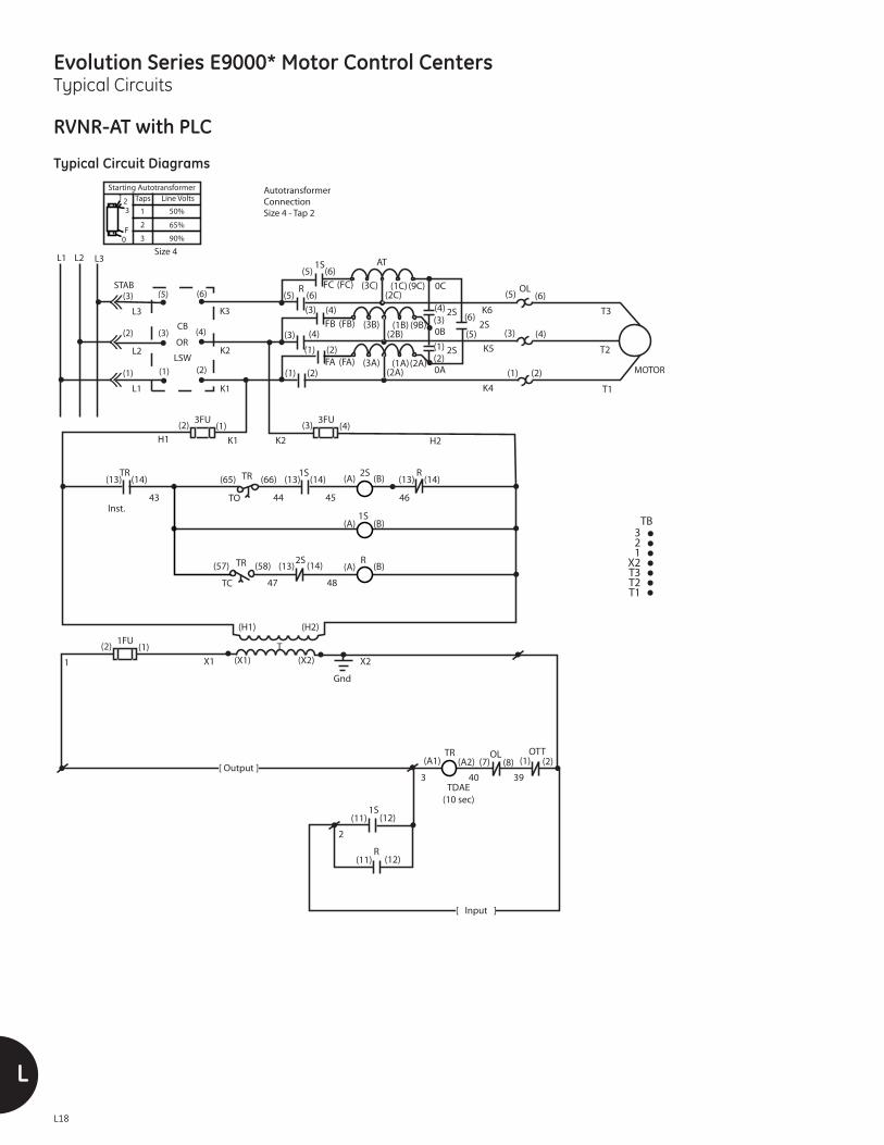
Evolution Series E9000* Motor Control CentersTypical Circuits
L18
L
RVNR-AT with PLC
Typical Circuit Diagrams
L1
L1
L2
L3
L2 L3Size 4
Autotransformer Connection Size 4 - Tap 2
CB
OR
LSW
(1)(1) (2)
(2) (4)
(6)(5)
(3)
(3)
K3
K2
K1
R1S
1S
R
TR TR
TR
TC
(H1) (H2)
TO
2S
2S
(13) (14)(13)(65) (66) (14)(13) (14)
3FU(1)(2)
3FU(4)(3)
STAB
H1 H2K1 K2
(A) (B)
(A)
(A)
(B)
(B)(13) (14)
464544
47 48
43
(7) (8)
1FU(1)(2)
1 X1 X2(X1) (X2)
Gnd
(A1)
39403
1S
R
(1)
(12)
(2)
(11)
(12)(11)
2
OL
TB3 2 1
X2 T3 T2 T1
MOTOR
T1
T2
T3
K4
K5
K6
(5) (5)(6) (6)
(3) (3)(4)
(3)(3)
(4) (4)
(4)
(1) (1)(2)
(1) (2)
(2)
R
(5)
(5)
(6)
(6)
1S
2S
AT
2S
OLFC (FC) (3C)(2C)
(1C) (9C) 0C
FB (FB) (3B)(2B)
(1B) (9B)0B
(2)(1) 2S
FA (FA) (3A)(2A)
(1A)(2A)0A
(57) (58)
T
TR OTT
TDAE (10 sec)
(A2)
Starting AutotransformerTaps Line Volts
50%
65%
90%
1
2
3
321
F0
Inst.
[ Input ]
[ Output ]

Evolution Series E9000* Motor Control CentersTypical Circuits
LL19
2S2W with PLC
Typical Circuit Diagrams
9 8 5 3 1
X2 T13 T12 T11
T3 T2 T1
(2) (1)1FU
L1
L1
L2
L3
L2 L3
CB
OR
LSW
(1)(1) (2)
(2) (4)
(6)(5)
(3)
(3)
K3
K2
K1
MOTOR
T11
T12
T13
T1
T2
T3
K5
K6
K4
K8
K7
K9
SS SOL(5) (6) (5) (6)
(5) (5)(6) (6)
(3) (4) (3) (4)
(3) (3)(4) (4)
(1) (1) (2)(2)
(1) (1)(2) (2)
FS FOLSTAB
1
2FU
SS
SS
SS
(B)
(B)
(A)
(A)
SOL(7) (8)
FOL(7) (8)(11)
(11)
(12)
(12)
3 4Ø 39
TB
X1 X2(X1) (X2)
Gnd
T
(H1) (H2)
6
FS
FS
FS
À
À
À
À
À
(14)
(14)
(13)
(13)
5
8
9
Polarity sensitive.
2S2W Ref GEN 1000A Fig 5
7
[ Output ]
[ Output ]
[ Input ]
[ Input ]

Evolution Series E9000* Motor Control CentersTypical Circuits
L20
L
ASTAT XT
Typical Circuit Diagrams

Evolution Series E9000* Motor Control CentersTypical Circuits
LL21
ASTAT XT Bypass
Typical Circuit Diagrams

Evolution Series E9000* Motor Control CentersTypical Circuits
L22
L
ASTAT XT Isolation Bypass
Typical Circuit Diagrams

Evolution Series E9000* Motor Control CentersTypical Circuits
LL23
ASTAT XT Bypass Emergency Bypass
Typical Circuit Diagrams

Evolution Series E9000* Motor Control CentersTypical Circuits
L24
L
ASTAT XT Isolation Bypass Emergency Bypass
Typical Circuit Diagrams

Evolution Series E9000* Motor Control CentersTypical Circuits
LL25
ASTAT BP
Typical Circuit Diagrams

Evolution Series E9000* Motor Control CentersTypical Circuits
L26
L
ASTAT BP Isolation
Typical Circuit Diagrams

Evolution Series E9000* Motor Control CentersTypical Circuits
LL27
Adjustable Speed DrivesAF-600 FP & AF-650 GP Drives
L1
CBSTAB[3]
[5]
[3]
[1]
[6]
[4]
[2]
[E104A]
L2 L3
L3[2]
L2
[1]
[A1]
[91][L1]
K1[1]
K2[3]
[92][L2]
[93][L3]
[98]
[C1]C1RED
11BLK
4–20mAOR0–10VDCREMOTE
F01 – [2] ANALOG INPUT 54F02 – [0] LINKED TO HAND/AUTOE24 RELAY 1 – [9] ALARME24 RELAY 2 – [5] RUNNINGE01 – [8] STARTE03 – [0] NO OPERATION
SETTINGS
[C2]
[B1] [B2]
[A1] [A2]
[54]
[55]
[53]
[50]
[88]
[89]
[95]
[14] [13] [START]
[+24V OUT]
[18][REVERSE]
[18]
[12][+24V OUT]
[COAST/LOW]
[13]
[20]
[27]
[JOG][29]
[32]
[33]
[4][2]
[2] [1]
[H1]
[X1]
727170212018
531
X2X211C1
TB DTB
[A1] [A2]
[X2]
[H2]
[81]
[61]
[69]
[39]
[68]
[82]
[42]
[97]
[96]
[99]
[06]
[05]
[04]
4
1
[03] 71
[02] 72
[01] 70
[B1] [C1]
[A2] [B2] [C3]
L1
REA
AF6
AF-600FP / AF-650GP
LFTR
DCBus
GND
GND
CM
H1 H2
T1FU
FWD
RUN
SHLD
RELAY 2(RUN)
BrakeResistor
RS-485Interface
AnalogOutput4-20mA
MOTOR
W T3
V T2
U T1
R S T
K3
K2
K1
GNDX2X1
JPR 18
5
4
20
21
3 JPRX2
RUN
[A1] [A2]RUNX
[13] [14]RUNX
[21] [22]RUNX
[04] [05]
AF6[RUN]
1
[1] [2]FAN2
[MLE] [FML]DRCNN
[MLE] [FML]DRCNN
[1] [2]FAN1
Note: See Section K for more circuits.

Evolution Series E9000* Motor Control CentersTypical Circuits
L28
L
High-Resistance Ground
Typical Circuit Diagrams
17 1/2"
15 3/4"
(4) 7/8" X5/8" DIA. SLOTS
3"
3"
2"
(4) 7/8" X5/8" DIA. SLOTS
2"
3"
3"
15 3/4"17 1/2"
6"
12"
12"
FRONT VIEW RIGHT SIDE VIEW
2 BANKS, EACH 17 1/2(1) 10 COILS/BANK. (1) 5 COILS/BANK. 2727-5P
TOP VIEW
LC660 LC660
LC210LC440
LC88 LC132
LC63 LC75
LC75 LC75
LC75 LC75
ENDFRAMES. TURN FLANGES IN. TERMINALS UP.FURNISH JUMPERS.
TOP BANK
BOTTOM BANK
N3
GND
N5
N6 N7
N4
N2
N1LC300 LC300
LC300GND
TEST
L1
L2
PX
NGR
TO 240-600V
GND
TO TEST RESISTOR
CUSTOMER CONNECTIONS
TO RESISTOR (PULSE LEVEL)
TO RESISTOR(FAULT LEVEL)
50
6
19
13
17 1216
15
1424
11
12
10
9
8
7
12 24
L1 T1
PULSING CONTACTOR
G
L2
PX
T2
15
TERMINAL
4
5
3
STRIP
1
2
32
L1
L1
L3
SW1
L2
L2
GND
12
24
10 11
SW1
13
L3
L3
External Horn
NeutralNeutral Voltage
Display Cable
GroundNeutralGroundNeutral Current
Gnd Fault AlarmSystem NormalPulseRelayFuture
Line ComCtrl Power
External Control
ResetSilence
Com
Operator Interface
13
15
GND
14 12
14
G
52 50 51
NO
COM
NC
GROUND FAULTALARM CONTACTS
52
SW1-L3
SW1-L2
SW1-L1
51
DISCONNECT SWITCH
FUSES
TB6
TB7
TB8
TB1
TB2
TB3
TB13
TB17
TB15
AS
SOURCE
T2
T3
37
36 40
30F7
F6
31F1
11
32
10
32F2
H130
H4
H3H2
14
X2
X1
(240-600/120V)
37
36
T1(240-600/120V)
T2
(240-600/120V)
H2
14 H4
H3
H414
40 H1
H3H2
31 H1
X2 36
X1 3537X1
X2 35
T3
10
31 40
F1 F6
11
30
F7
32
33
.8A
F2
32
35T1
240-600V(L-L)
14
18 16 TR
TB14
19TR
TEST RESISTOR
F3
GNDTO GROUND BUS
32
13
FUSES
F7
3.5A
2.5A
F6NGR
1-10A
1-7A
F1
2.5A
3.5A 3.5A
2.5A
PB1
SYSTEM TEST
1816
PB1
SYSTEM TEST
3.5A
32
F3 F4
11
.8A
34
G
33
F434 11
20TR
20
2 4
6 8
19
163
17 G
0
UNDER VOLTAGE RELAY
UVR
17
UVR
17 18
TB12
GND
7 8
13
1
6 5
UVR
4
14
2
3
17
G
13 33
34CPT
TB
(50 OR 60 Hz)
(SYSTEM NORMAL)
GND
PX-T1
PX-L1
TB15TB17
SYMBOL
F(X)
GND
PB1
SW1
NGR
PX
AS
DISCONNECT SWITCH
TEST PUSHBUTTON
PULSING CONTACTOR
DESCRIPTION
GROUND BUS
ARC SUPPRESSOR
NEUTRAL GRD RESISTOR
LINE FUSE
CPT CONTROL POWER TRANSFORMER
T(X) TRANSFORMER
TEST RESISTOR
TEST RELAYTR
OPTIONAL EQUIPMENT
ALL INTERNAL CONTROL WIRING TO BE 600V,#14 AWG TERMINATED W/PREINSULATED SHANKRING & COMPRESSION TERMINAL. RESISTOR WIRINGTO BE #8 TEFLON WIRE. EQUIPMENT & DEVICEGROUND WIRE SHALL BE INDEPENDENTLYTERMINATED ON THE GROUND BUS.
1.
CONTROL POWER TRANSFORMER
NOTES
2. DASHED CONNECTIONS TO BE MADE BY CUSTOMER.
UNDER VOLTAGE RELAYUVR
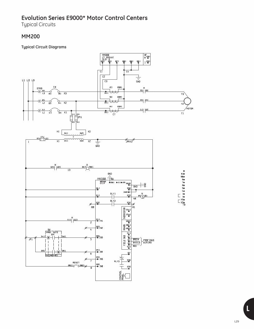
Evolution Series E9000* Motor Control CentersTypical Circuits
LL29
MM200
Typical Circuit Diagrams

Evolution Series E9000* Motor Control CentersTypical Circuits
L30
L
MM300
Typical Circuit Diagrams

MM1
Evolution Series E9000 Motor Control CentersSpecifications
Specification for Motor Control Centers600 Volts and Below
1.0 GeneralThis specification covers low voltage motor control centerswith combination starter units.
1.1 StandardsThe motor control centers shall be manufactured and tested inaccordance with NEMA ICS 2-3 and UL Standard 845. Verticalsections and individual units shall be UL Labeled where possible.
1.2 ServiceEach motor control center shall be suitable for use on a_______ volt, three phase, _____ wire, ______ Hertz power system having a short circuit availability of _____________amperes RMS symmetrical.
1.3 WiringWiring shall be NEMA Class [ I ] [ II ], Type [ A ] [ BD ] [ BT ] [ C ]. Where Type C wiring is required, the master terminalblocks shall be located at the [top] [bottom] of the verticalsection. Combination starter units shall be wired out to splittype terminal blocks for easy removal of the starter unitwithout disturbing either factory or field installed wiring. Allcontrol terminal boards shall be accessible from the front.
2.0 ConstructionIndoor enclosures shall be NEMA Type [1- Gasketed] [2] [12 ].Indoor enclosures shall be suitable for front mounting. Outdoorenclosures when specified, shall be NEMA [3R Non-Walk-In]or [3R Walk-in]. The motor control center shall be seismicrated for UBC/CBC Zone 4.
Each motor control center shall consist of the required numberof vertical sections of heavy gauge sheet steel bolted togetherto form a rigid self-supporting assembly. A removable liftingangle shall be mounted to the motor control center at thetop. Removable bottom channel sills shall be mounted frontand rear of the vertical sections and shall extend the widthof the lineup.
Motor control center vertical sections shall be nominally 90-inch high and 20-inch deep. Alternate section heights shallbe 78" or 66". Alternate section widths shall be 24-inches or30-inches wide when required.
2.1 Horizontal WirewayEach vertical section shall contain a minimum 12-inch high tophorizontal wireway and a 6” bottom wireway. When loads exitthe bottom a 12” bottom wireway shall be provided. The hori-zontal wireway shall be covered by a removable hinged door.
2.2 Vertical Wiring TroughA separate vertical wiring trough shall be furnished in eachvertical section adjacent to plug-in unit. The wire trough shall
permit the installation of field wiring and shall isolate this wiringfrom the adjacent unit. No terminal blocks shall be locatedin the vertical wireway. Cable tie supports shall be furnishedin the vertical wireway to hold cable and wiring in place. Thevertical wiring trough shall be covered by a removablehinged door. [A low-level signal raceway shall be provided.]
3.0 Incoming Power/ Main Protective DeviceIncoming power to the motor control center shall be [cable][bus duct]. [Incoming power cables shall enter the [top] [bot-tom] of the motor control center.] [Incoming cables shall beof the size and number shown on the plans.] [Incoming busduct shall enter the top of the motor control center and shallhave a current rating as shown on the plans.]
The motor control center main protective device shall be a[molded case circuit breaker] [insulated case circuit breaker][fused switch]. The main device shall be of the ampere ratingshown on the plans and shall have an interrupting ratingequal to or greater than the available short circuit current.
4.0 Bus System
4.1 Main Horizontal BusPower shall be distributed by means of a continuous horizontalbus with a current rating of [600] [800] [1200] [1600] [2000][2500] amperes. The main bus shall be [tin-plated .0003 inchthick] [standard silver-plated .0002 inch thick] [heavy silver-plated .0005 inch thick] copper. The main bus shall be bracedfor [65,000][100,000] amperes RMS symmetrical. The mainbus shall be isolated by barriers from wire troughs, starters,and other areas. There shall be double bolt connections onmain bus joints and splice connections. Main bus splicingbetween shipping splits shall be accomplished from thefront with no structural disassembly. The main bus shall befully rated and arranged for future extension.
4.2 Vertical BusThe vertical bus in each section shall be rated [300] [600][850]*amperes and shall be [tin-plated] [silver-plated].*(1200A Main bus or greater)
The vertical bus shall be braced for [65KAIC] [100KAIC]. Thevertical bus shall have a flame-retardant polyester-glassinsulation / isolation system. This system shall insulate thevertical bus front and rear. In addition, the barrier shall isolateeach phase bus. Openings in the vertical bus insulation/iso-lation system shall permit the entry of unit stabs. Unusedopenings shall have plugs or covers to prevent the entry offoreign objects. [The openings in the vertical bus used forstarter connections shall be covered by an automatic shuttermechanism. The shutters shall automatically cover theopenings when the starter is removed.]
The vertical bus bracing AIC rating shall be the same as themain horizontal bus.

M2
M
Evolution Series E9000 Motor Control CentersSpecifications
4.3 Ground BusA copper ground bus shall extend the full width of the motorcontrol center. The ground bus shall be rated [300] [600]amperes. The ground bus shall be drilled and lugs furnishedas specified. [There shall be a vertical copper ground bus ineach section. This ground bus shall be accessible to a busstab mounted in the unit compartment area and arrangedso that the unit ground stab engages before the powerstabs engage the vertical bus]. [A motor load ground lugshall be mounted in the unit and used for terminating theground of multi-conductor cables.]
4.4 Neutral BusA neutral bus shall be furnished when shown on the plans.The neutral bus shall be [300] [600] [800] [1000] [1200] [1250].The neutral bus shall [be in the incoming section only][extend the full-width] of the motor control center. When aneutral bus is specified, bottom plates shall be furnished.Lugs of the proper ampacity shall be furnished.
5.0 UnitsCombination motor controller and feeder units shall employ[molded case circuit breakers] [fusible switches with clips for J or R type fuses] for branch circuit protection. Circuit breakerdisconnects for combination motor starters shall be [thermal-magnetic] [magnetic only].
All combination starter and feeder units of plug-in constructionshall utilize a positive guidance system to insure positiveconnection of the unit stabs to the section vertical bus.Insertion and removal of each unit shall not require the useof special tools. Unit shelves shall be of a lift out design.Connection from the power stabs to the unit disconnectshall be a direct connection. Each circuit breaker starter unitsize 1 through size 5 shall be of plug-in construction. Eachcircuit breaker feeder 600A or less shall be plug-in.
Each unit compartment shall be equipped with a flange-formedpan type door. The door shall be mounted on the verticalsection with removable hinges.
Each unit shall be equipped with an operating handle. Thehandle shall be connected to the disconnect operator using adirect drive and requiring no adjustment of linkage. The handleshall be mechanically interlocked with the door, preventingdoor opening with disconnect closed. The interlock shall alsoprevent disconnect being closed with the door open and preventthe unit from being removed or installed with disconnect ON.The interlock shall be capable of being defeated, allowing thedoor to be opened with disconnect closed or disconnect closedwith the door open. The unit handle shall have provision forpadlocking in the off position. On circuit breaker units thehandle shall have a “tripped” position in addition to OFF/ON.
Each unit shall be capable of being padlocked in a partiallywithdrawn position. In this position, the unit power stabs are
disengaged from the vertical bus and no power can enterthe unit.
Combination starter units specified with Type B or C wiringshall be supplied with split-type terminal blocks. These terminalblocks shall be mounted in front of the unit and shall allow theremoval of the unit without disconnecting any of the controlwiring. Combination starter units up to size 5 shall be plug-inconstruction and shall be capable of being removed withoutdisconnecting any control leads from their terminal blocks.
Overload relays shall be: {select one}
[Bimetallic, ambient compensated]
[Bimetallic, non-ambient compensated]
[Solid-state, ambient insensitive, self powered, adjustableFLA, adjustable phase unbalance, phase loss protection,and selectable overload class (10, 20, 30) with 2% accuracyand repeatability, built-in thermal memory to prevent hotmotor starts, isolated 1NO and 1 NC auxiliary contacts]
[Advanced microprocessor based motor protection, Dipswitch selectable Phase loss protection/Phase Unbalance,adjustable FLA, Selectable overload class (10, 20, 30)]
[Ground fault protection]
Provisions to Communicate over the following Protocol: [DeviceNet] [Modbus RTU]
The following minimum information shall be available overthe Network. • Metering (Average Phase Current in Amps, Control Voltage,Motor Run Time)
• Starter Status and Configuration Notification (Run,Overload, Ground Fault, Phase Unbalance, CommandedTrip, Class setting)
• Information (Voltage, Internal failure, 100% Motor LoadWarning)
• Remote Control (On, Off, Trip, Reset)
[Provide a Display Module for accessing at the unit all Networkdata] [Door mounted] [Hand held using phone jack on the door].
Control power for starter units shall be from: {select one}
[Individual control power transformers furnished in eachstarter unit. One secondary lead shall be furnished with afuse and the other lead shall be grounded. Control powerprimary fuses are required].
[Line voltage. Control circuits on all starter units with linevoltage control power shall be provided with current limitingfuses mounted in both legs of the control circuit].
[Separate source (common control)] Two wired terminalpoints shall be provided. One leg shall be wired through anormally open auxiliary contact in each disconnect and acontrol power fuse rated 1 amp shall be provided.]

MM3
Evolution Series E9000 Motor Control CentersSpecifications
Starter units shall be provided with the following auxiliarydevices:
[auxiliary starter interlocks, ______ N/O, ______N/C].
[control / timing relays (as shown on the drawings)].
[door mounted pilot devices: Start-stop pushbutton, H-O-Aselector switch, Indicating lights (quantity and color)].
Miscellaneous Units
The following units shall be included in the motor controlcenter(s) as indicated on the drawings:
[Lighting and Power transformers]
[Lighting panelboards]
[Power metering and associated instrument transformers,where required]
[Power factor correction capacitors]
[Reduced Voltage Solid State]
[Variable Frequency Drives]
[PLC’s]

GE41 Woodford AvenuePlainville, CT 06062www.geindustrial.com
Imagination at work
* Indicates a trademark of the General Electric Company and/or its subsidiaries.
Information provided is subject to change without notice. Please verify all details with GE. All values are design or typical valueswhen measured under laboratory conditions, and GE makes no warranty or guarantee, express or implied, that such performancewill be obtained under end-use conditions.
DET-291H 1217