motivation: smartphone market - ieee
TRANSCRIPT
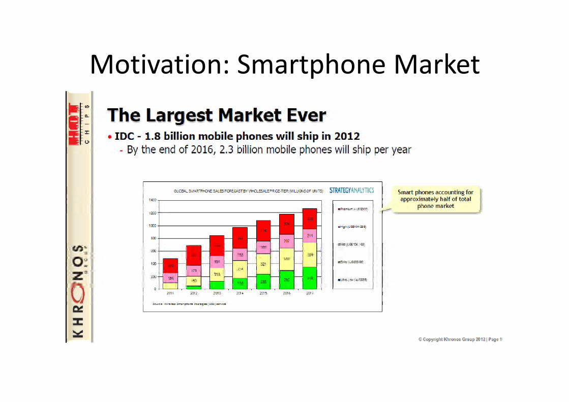
Motivation: Smartphone Market
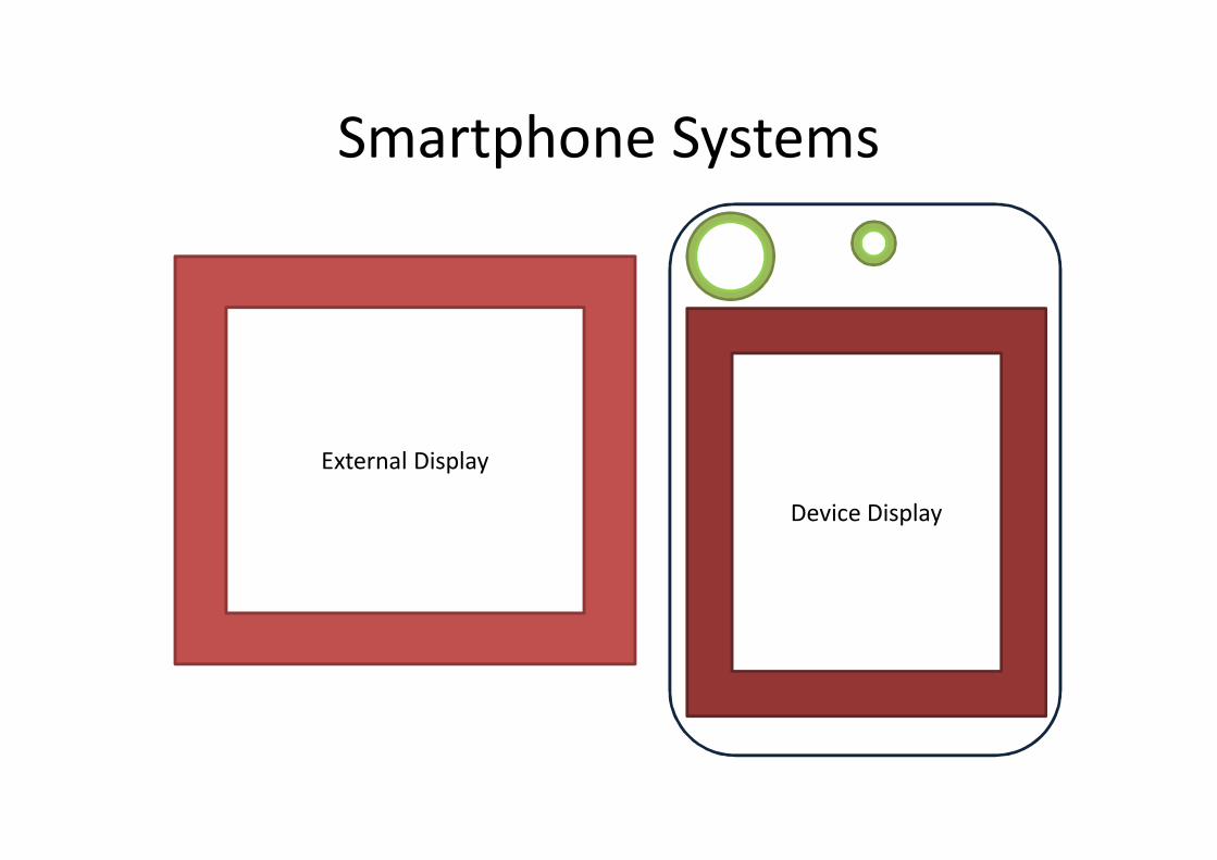
Smartphone Systems
Device Display
External Display
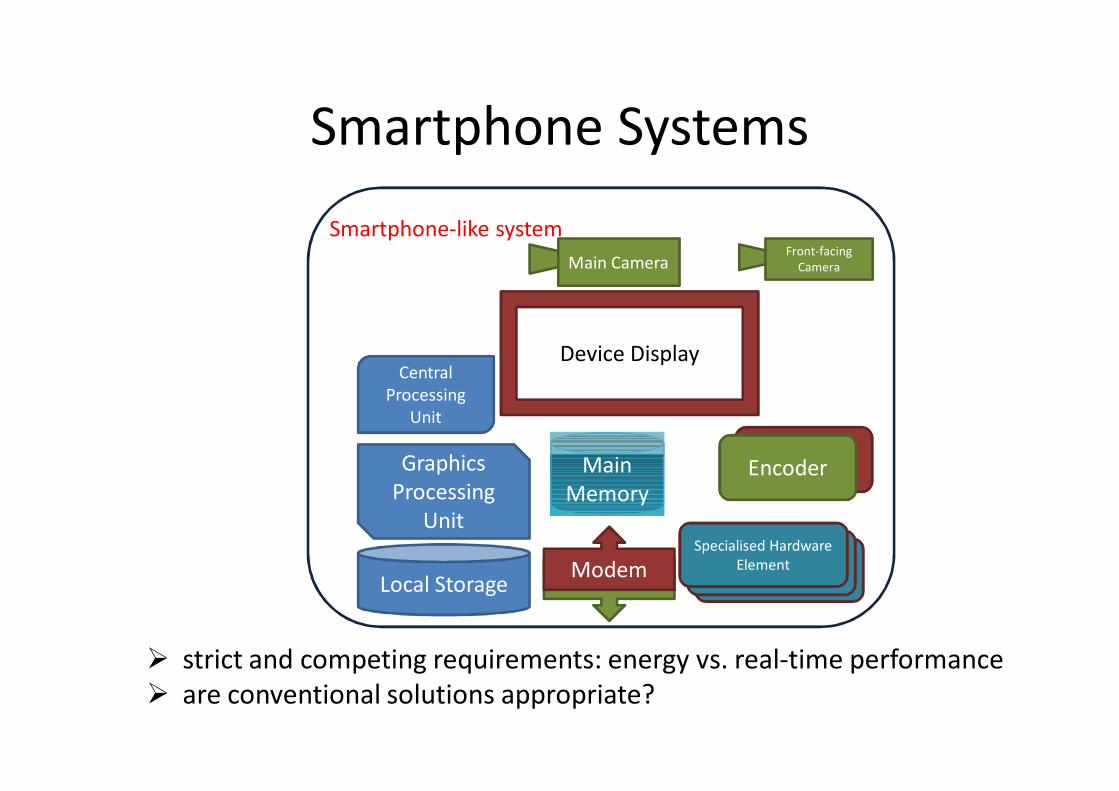
Smartphone Systems
strict and competing requirements: energy vs. real-time performance are conventional solutions appropriate?
Modem
Decoder
Modem
Device Display
Main CameraFront-facing
Camera
Main Main Memory
Central Processing
Unit
Graphics Processing
Unit
Specialised Hardware Element
Smartphone-like system
Local StorageSpecialised Hardware
Element
Specialised Hardware Element
Encoder

This work• a step towards smartphone-appropriate memory
scheduler designs• trace-based methodology
– memory traces with dependence information• software-based methodology to approximate hardware
accelerator behavior• we study:
– address mapping schemes– memory schedulers– Video Conference Workload– other smartphone workloads

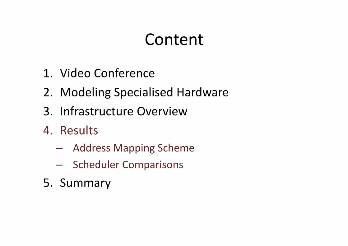
Content
1. Video Conference2. Modeling Specialised Hardware3. Infrastructure Overview4. Results– Address Mapping Scheme– Scheduler Comparisons
5. Summary

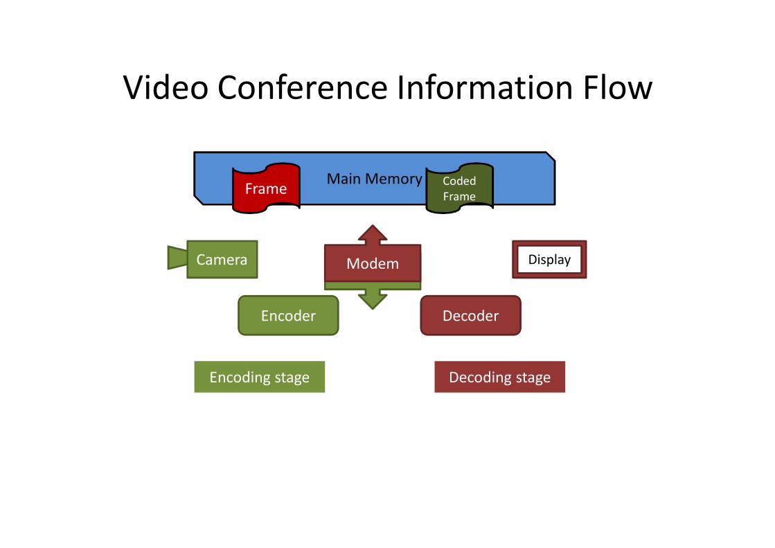
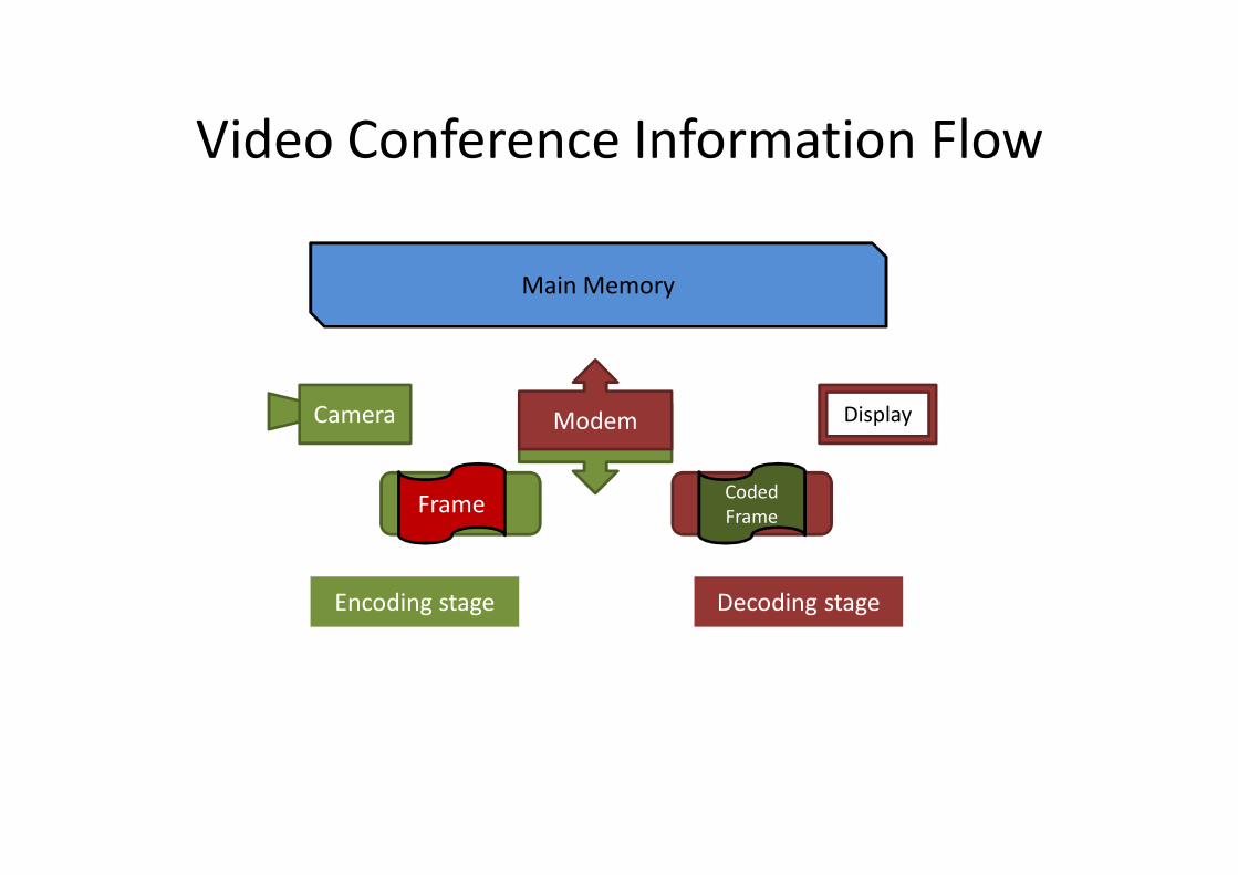
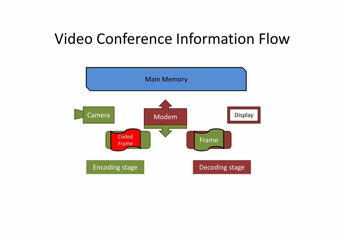
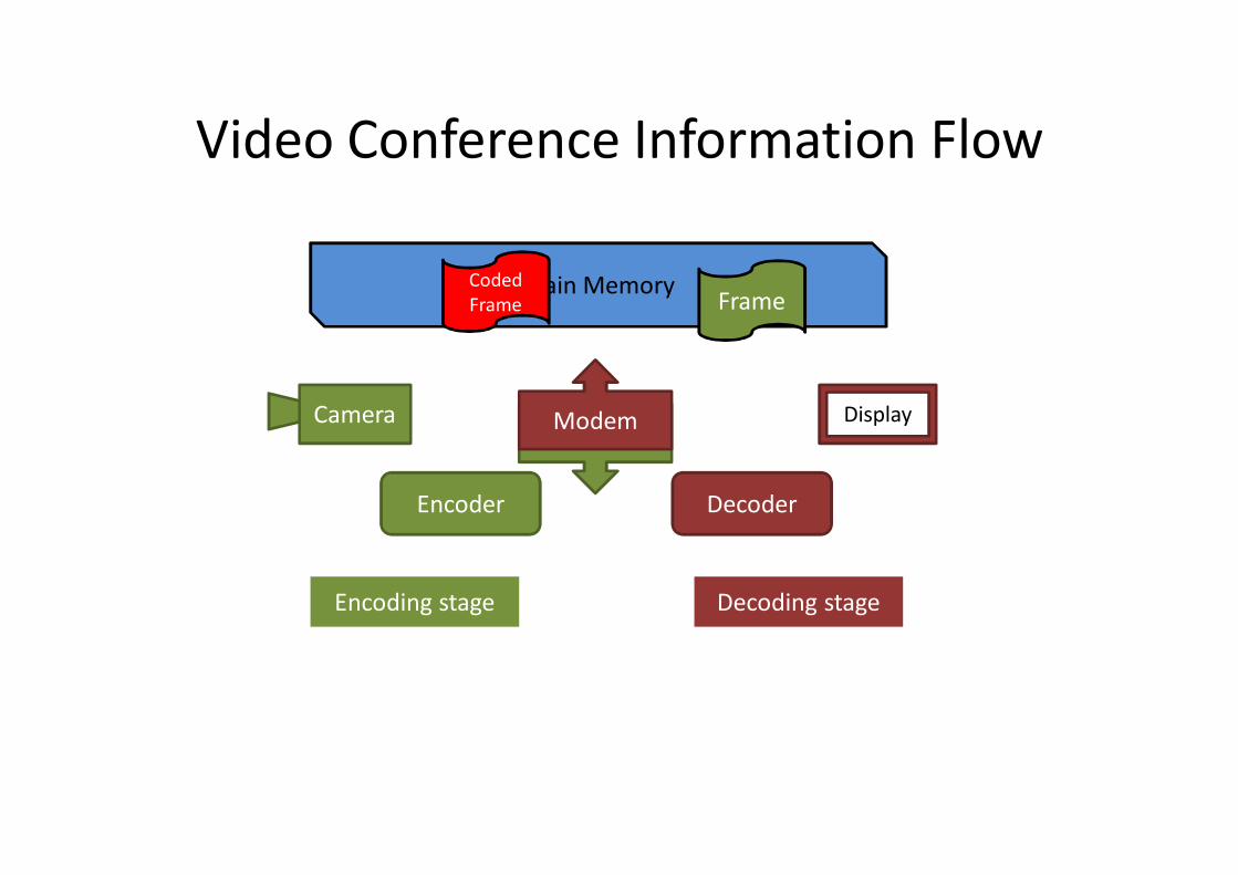
Video Conference
• two-way video call– a conversation between 2 persons, a video
conference between meeting rooms, etc.
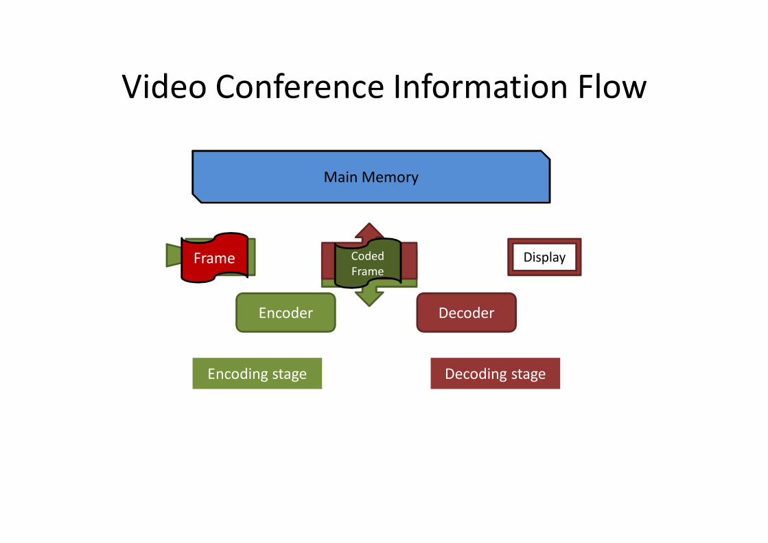
DecoderEncoder
Video Conference Information Flow
Main Memory
ModemModem Display
Encoding stage Decoding stage
CameraFrame Coded Frame
DecoderEncoder
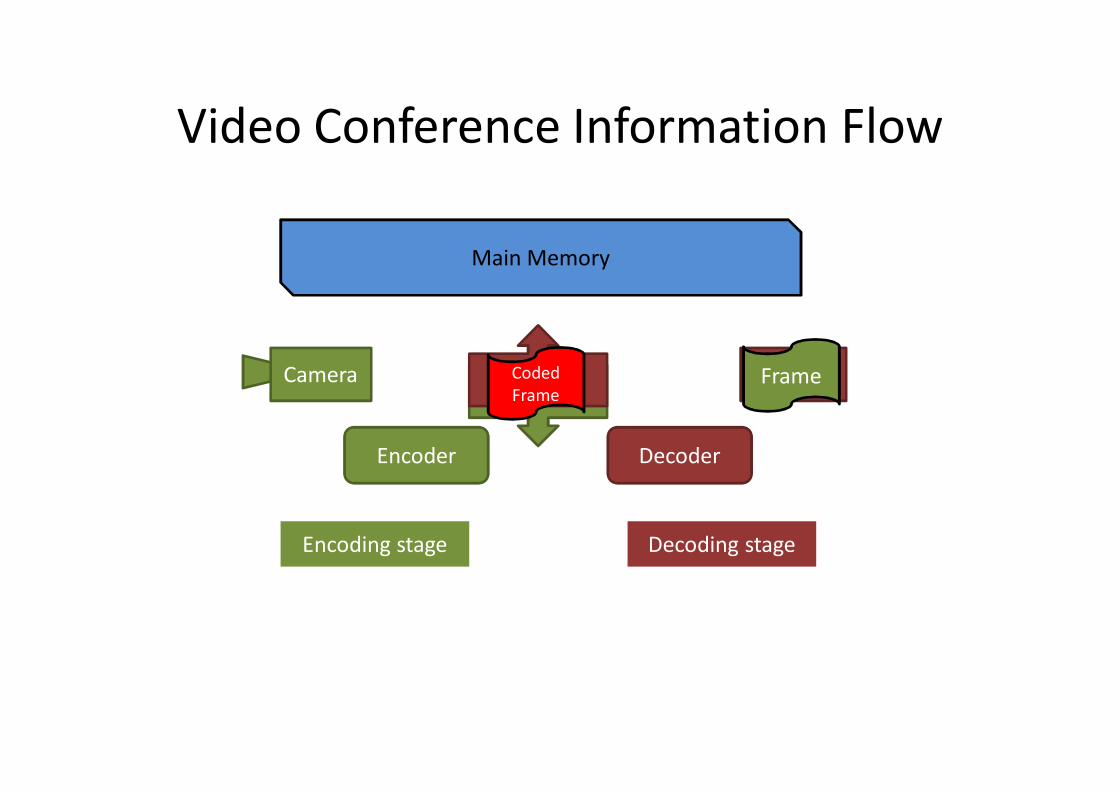
Video Conference Information Flow
Main Memory
ModemModem Display
Encoding stage Decoding stage
Camera
Frame Coded Frame
DecoderEncoder
Video Conference Information Flow
Main Memory
ModemModem Display
Encoding stage Decoding stage
Camera
Frame Coded Frame
DecoderEncoder
Video Conference Information Flow
Main Memory
ModemModem Display
Encoding stage Decoding stage
Camera
Coded Frame Frame
DecoderEncoder
Video Conference Information Flow
Main Memory
ModemModem Display
Encoding stage Decoding stage
Camera
Coded Frame Frame
DecoderEncoder
Video Conference Information Flow
Main Memory
ModemModem Display
Encoding stage Decoding stage
Camera Coded Frame
Frame
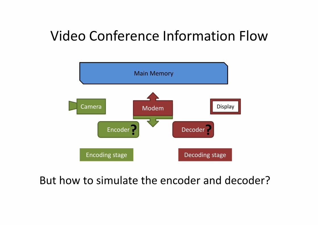
DecoderEncoder
Video Conference Information Flow
But how to simulate the encoder and decoder?
Main Memory
ModemModem Display
Encoding stage Decoding stage
Camera
? ?
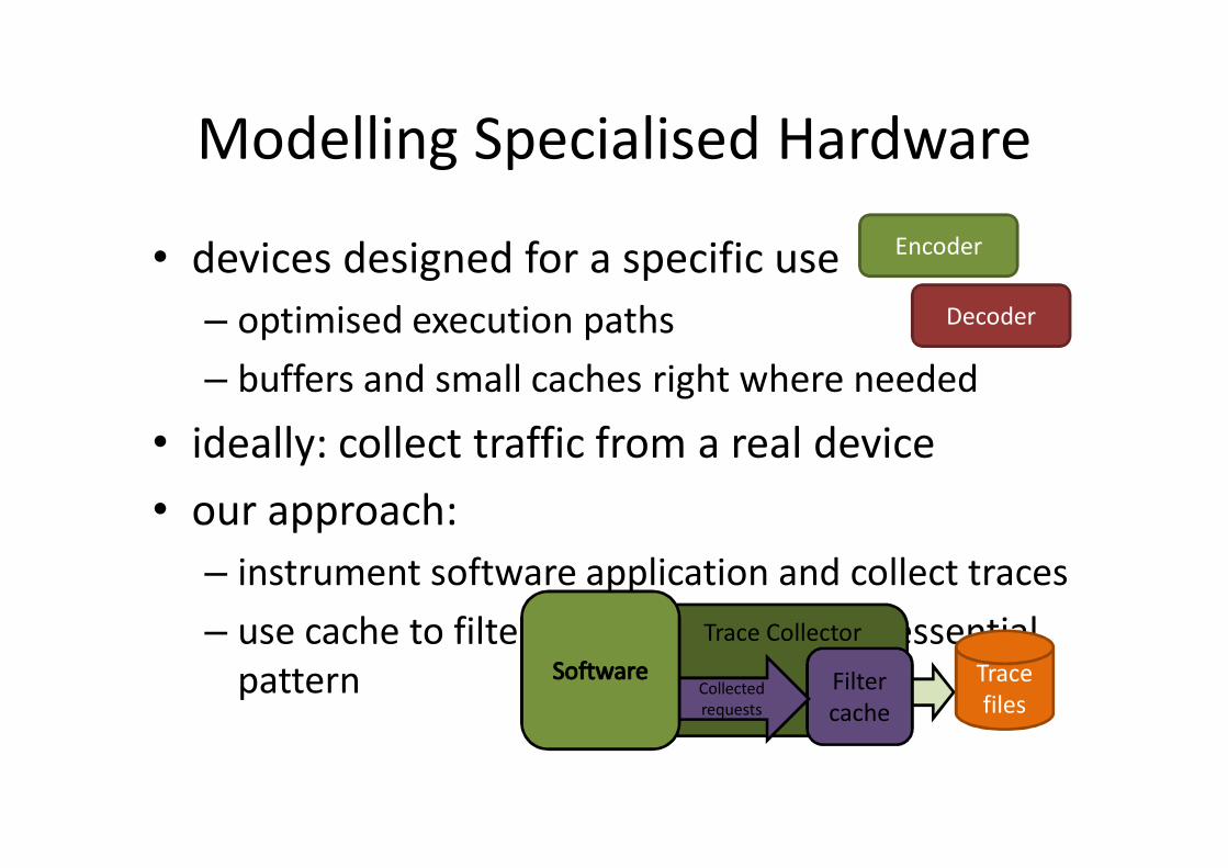
Modelling Specialised Hardware
• devices designed for a specific use– optimised execution paths– buffers and small caches right where needed
• ideally: collect traffic from a real device• our approach:
– instrument software application and collect traces– use cache to filter accesses and get the essential
pattern
Decoder
Encoder
Trace Collector
Filtercache
Collected requests
Trace files
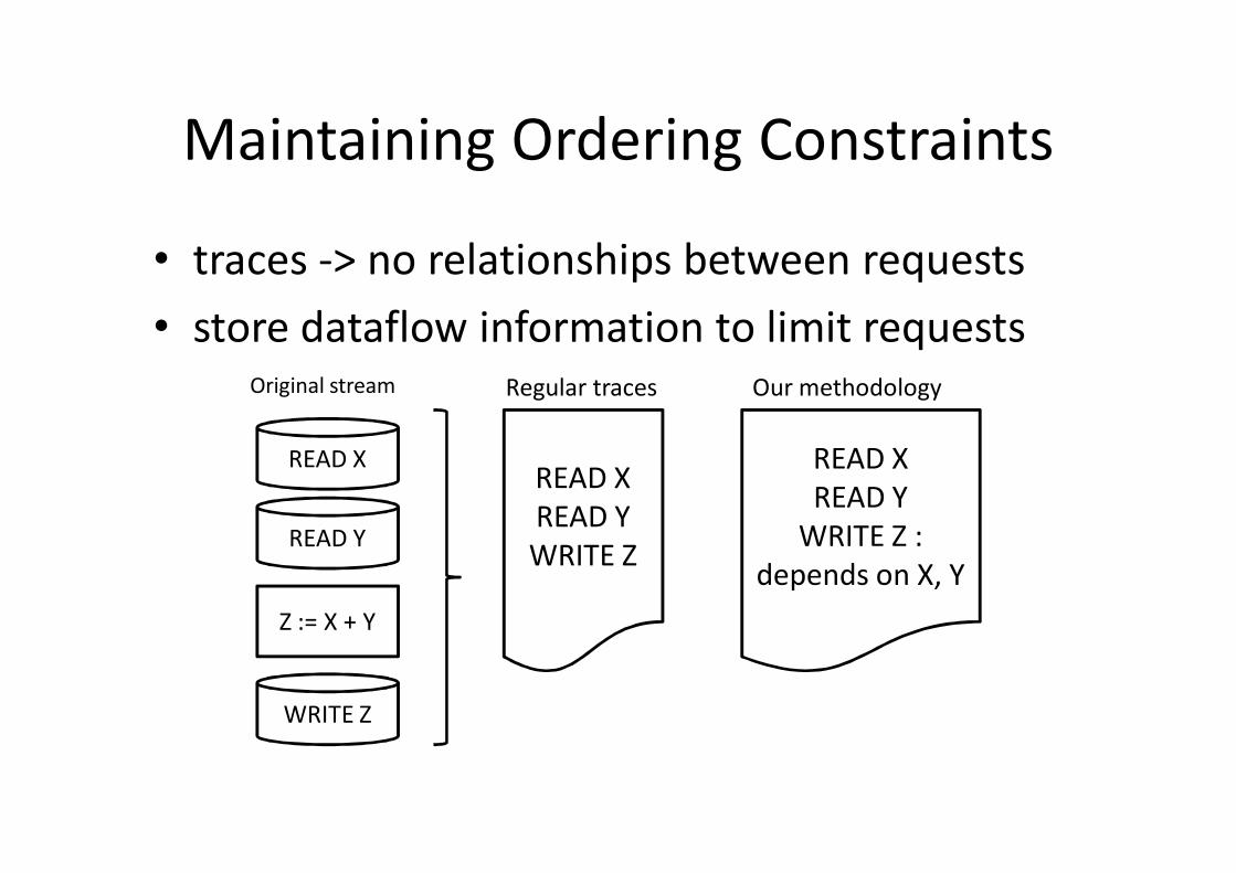
Maintaining Ordering Constraints
• traces -> no relationships between requests• store dataflow information to limit requests
READ X
READ Y
WRITE Z
Z := X + Y
READ XREAD YWRITE Z
Original stream Regular traces Our methodology
READ XREAD Y
WRITE Z : depends on X, Y
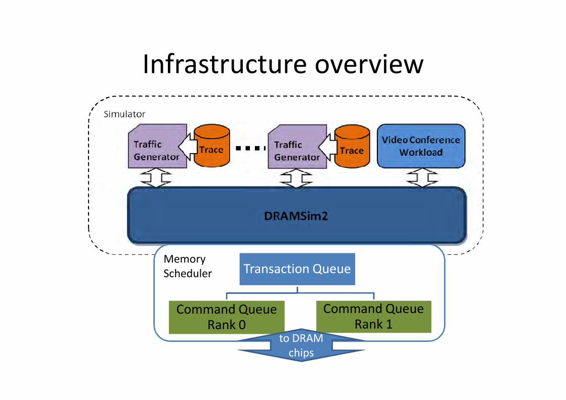
Infrastructure overview
MemoryScheduler Transaction Queue
Command Queue Rank 0
Command Queue Rank 1
to DRAM chips
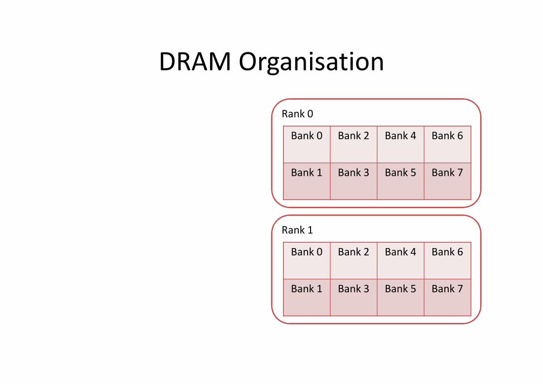
DRAM Organisation
Bank 0 Bank 2 Bank 4 Bank 6
Bank 1 Bank 3 Bank 5 Bank 7
Rank 1
Bank 0 Bank 2 Bank 4 Bank 6
Bank 1 Bank 3 Bank 5 Bank 7
Rank 0
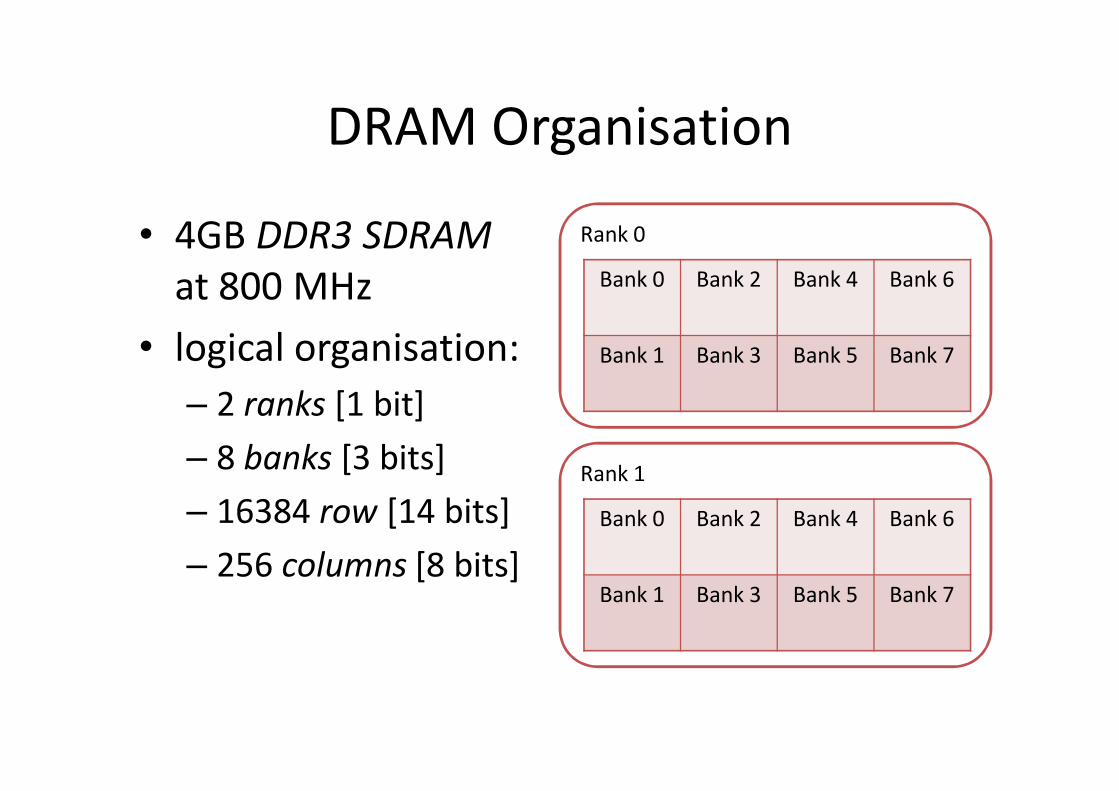
DRAM Organisation
• 4GB DDR3 SDRAMat 800 MHz
• logical organisation:– 2 ranks [1 bit]– 8 banks [3 bits]– 16384 row [14 bits]– 256 columns [8 bits]
Bank 0 Bank 2 Bank 4 Bank 6
Bank 1 Bank 3 Bank 5 Bank 7
Rank 1
Bank 0 Bank 2 Bank 4 Bank 6
Bank 1 Bank 3 Bank 5 Bank 7
Rank 0
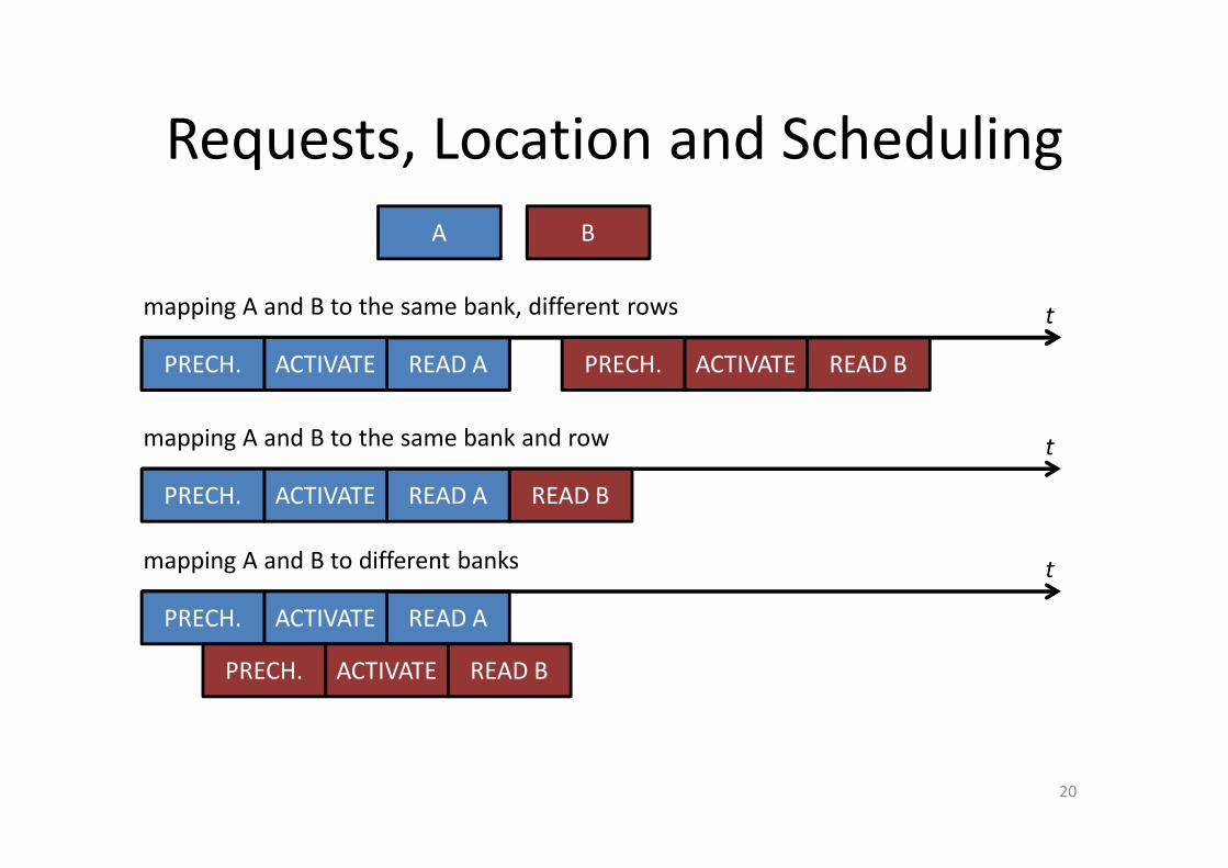
Requests, Location and Scheduling
20
READ A
B
t
ACTIVATEPRECH. READ BACTIVATE
mapping A and B to the same bank, different rows
A
READ A
t
ACTIVATEPRECH.
READ BACTIVATEPRECH.
mapping A and B to different banks
READ A
t
ACTIVATEPRECH. READ B
mapping A and B to the same bank and row
READ AACTIVATEPRECH. PRECH.
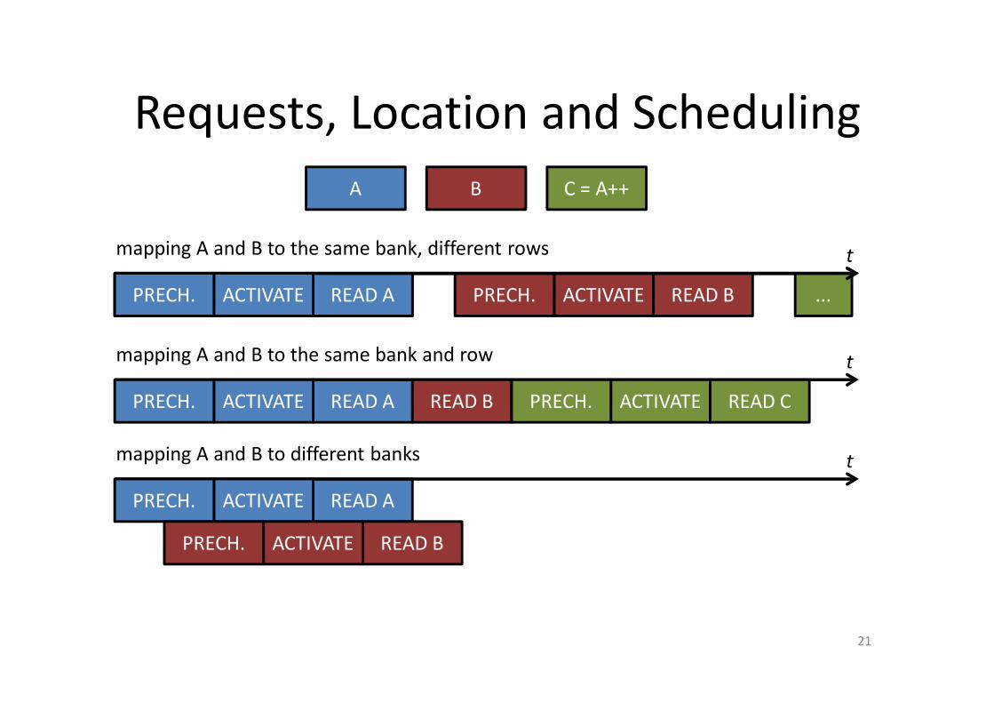
Requests, Location and Scheduling
21
READ A
B C = A++
t
ACTIVATEPRECH. READ BACTIVATEPRECH.
mapping A and B to the same bank, different rows
A
READ A
t
ACTIVATEPRECH.
READ BACTIVATEPRECH.
mapping A and B to different banks
READ A
t
ACTIVATEPRECH. READ B
mapping A and B to the same bank and row
...
ACTIVATEPRECH. READ C
READ AACTIVATEPRECH.
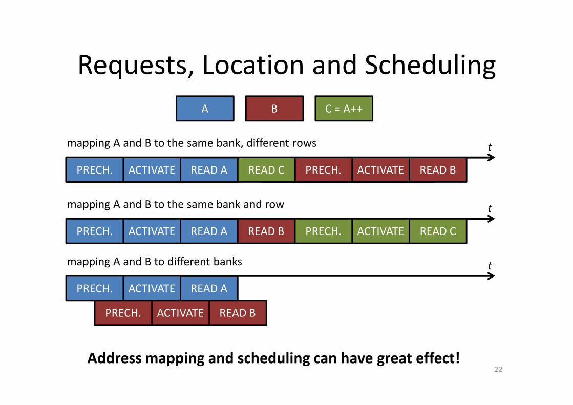
Requests, Location and Scheduling
22
READ A
B C = A++
t
ACTIVATEPRECH. READ BACTIVATEPRECH.
mapping A and B to the same bank, different rows
A
READ A
t
ACTIVATEPRECH.
READ BACTIVATEPRECH.
mapping A and B to different banks
READ A
t
ACTIVATEPRECH. READ B
mapping A and B to the same bank and row
ACTIVATEPRECH. READ C
READ AACTIVATEPRECH. READ BACTIVATEPRECH.READ C
Address mapping and scheduling can have great effect!
Content
1. Video Conference2. Modeling Specialised Hardware3. Infrastructure Overview4. Results– Address Mapping Scheme– Scheduler Comparisons
5. Summary
Content
1. Video Conference2. Modeling Specialised Hardware3. Infrastructure Overview4. Results– Address Mapping Scheme– Scheduler Comparisons
5. Summary
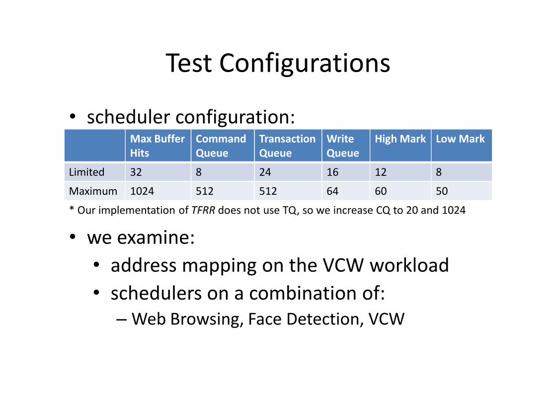
Test Configurations
• scheduler configuration:Max Buffer Hits
Command Queue
Transaction Queue
Write Queue
High Mark Low Mark
Limited 32 8 24 16 12 8
Maximum 1024 512 512 64 60 50
* Our implementation of TFRR does not use TQ, so we increase CQ to 20 and 1024
• we examine:• address mapping on the VCW workload• schedulers on a combination of:
– Web Browsing, Face Detection, VCW
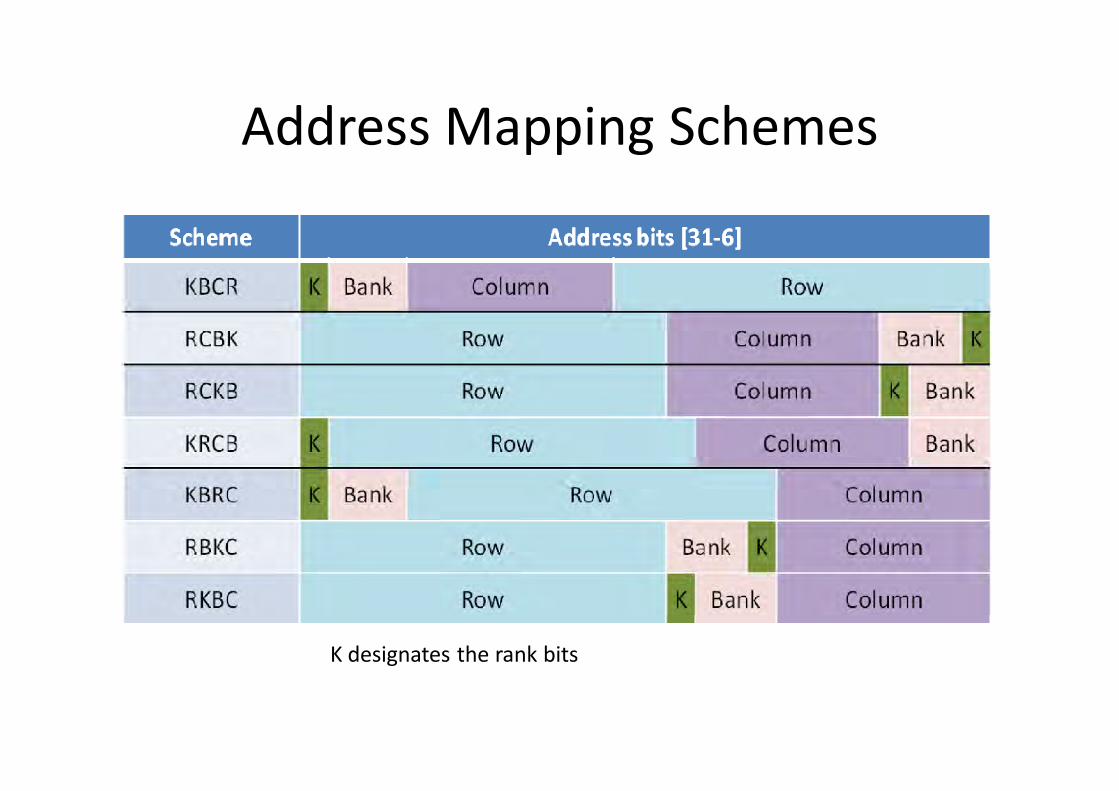
Address Mapping Schemes
K designates the rank bits
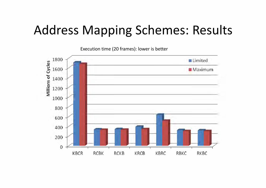
Address Mapping Schemes: ResultsExecution time (20 frames): lower is better
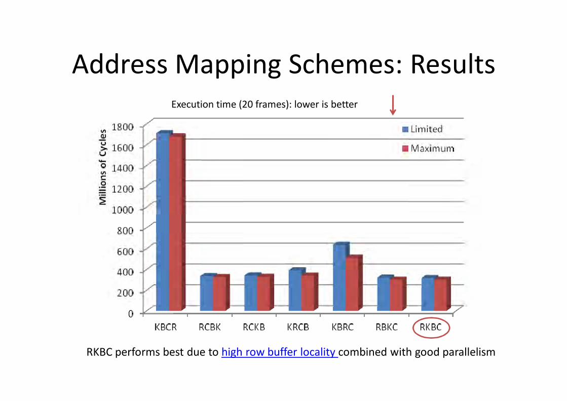
Address Mapping Schemes: ResultsExecution time (20 frames): lower is better
RKBC performs best due to high row buffer locality combined with good parallelism
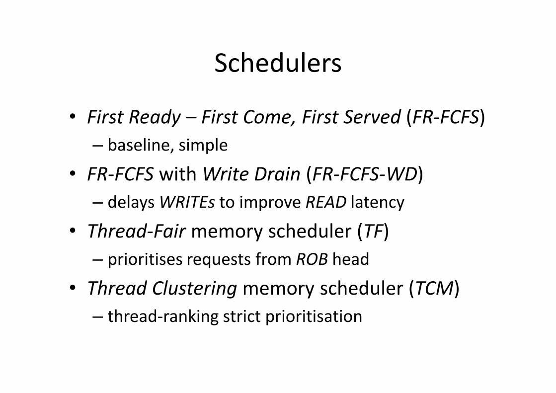
Schedulers
• First Ready – First Come, First Served (FR-FCFS)– baseline, simple
• FR-FCFS with Write Drain (FR-FCFS-WD)– delays WRITEs to improve READ latency
• Thread-Fair memory scheduler (TF)– prioritises requests from ROB head
• Thread Clustering memory scheduler (TCM)– thread-ranking strict prioritisation
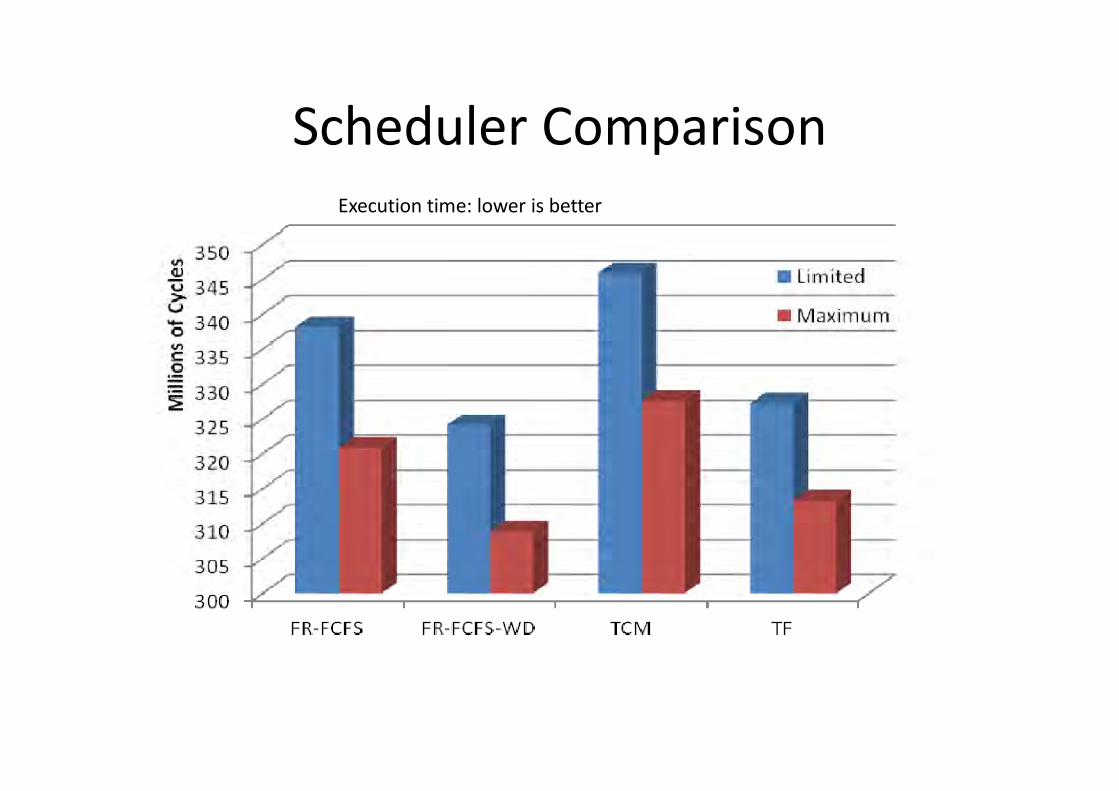
Scheduler ComparisonExecution time: lower is better
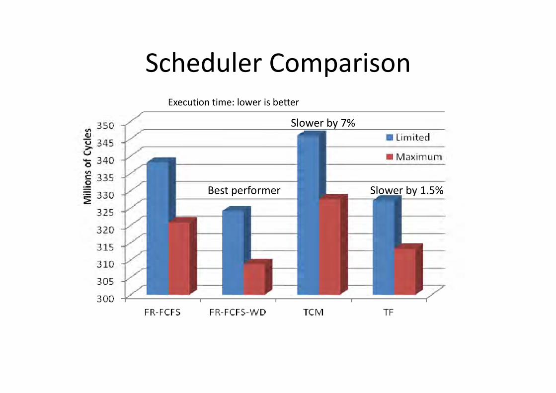
Scheduler ComparisonExecution time: lower is better
Best performer
Slower by 7%
Slower by 1.5%
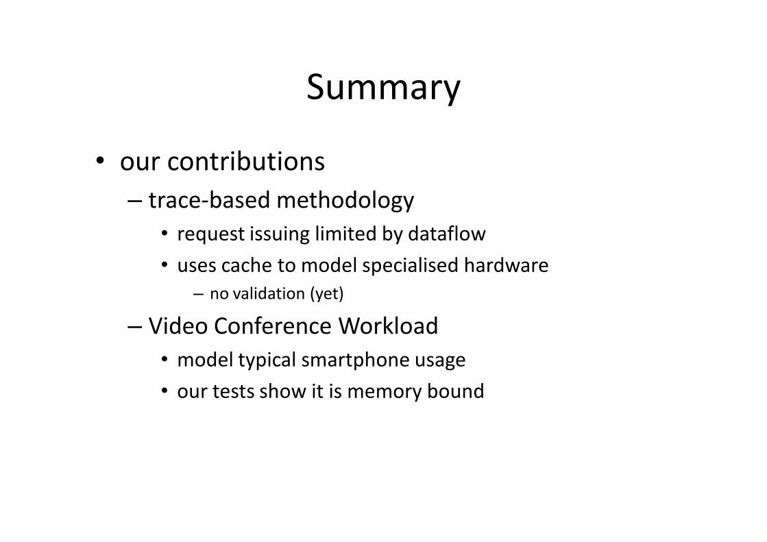
Summary
• our contributions– trace-based methodology
• request issuing limited by dataflow• uses cache to model specialised hardware
– no validation (yet)
– Video Conference Workload• model typical smartphone usage• our tests show it is memory bound
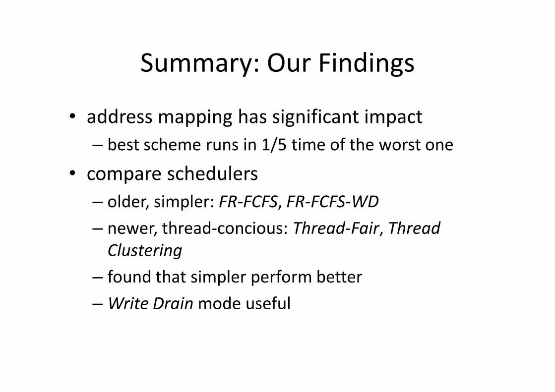
Summary: Our Findings
• address mapping has significant impact– best scheme runs in 1/5 time of the worst one
• compare schedulers– older, simpler: FR-FCFS, FR-FCFS-WD– newer, thread-concious: Thread-Fair, Thread
Clustering– found that simpler perform better– Write Drain mode useful

THANK YOU FOR YOUR ATTENTION!