physicssmarshallsay.weebly.com/uploads/3/1/4/6/3146892/ah_student_notes.pdf · circular motion...
TRANSCRIPT

Physics Student Material Advanced Higher
6581


Spring 2000
Physics
Student Materials
Advanced Higher
Support Materials
HIGHER STILL

This publication may be reproduced in whole or in part for educational purposes provided that no profit
is derived from the reproduction and that, if reproduced in part, the source is acknowledged.
First published 2000
Higher Still Development Unit
PO Box 12754
Ladywell House
Ladywell Road
Edinburgh
EH12 7YH

Physics (AH): Student Materials
CONTENTS
This pack contains the following material:
Correction pages: Support materials part 1 - Mechanics
Electrical Phenomena - Student Material
Wave Phenomena - Student Material
Summary
[Note: Solutions to tutorial questions will be published separately.]

Physics (AH): Student Materials
Physics (AH): Mechanics - Student Materials
ADVANCED HIGHER
Support Material – Part 1
Correction pages for Mechanics – Student Support Material.
The corrections are summarised below and copies of the relevant pages follow.
Page 3
First bullet point under Calculations Involving Uniform Acceleration:
g should be = 9.8 m s-2
vertically downwards
The negative sign should be deleted.
Page 19
Assumptions made by Newton
Delete the sentence in parentheses under the first bullet point.
The present sentence could be misleading. When considering gravitational forces
outside a sphere of uniform density, it can be shown by integration that we can
replace the mass of the sphere by a point mass at its centre. This applies equally when
considering gravitational forces between planets and/or stars with large separations, or
between the Earth and an object on the surface of the Earth.
page 46 Tutorial 4 Q 7
The equation for power, P = T is not required. The torque is now given.
page 48 Tutorial 5 Q 3
The mass of the satellite is required.
page 52 Tutorial 7 Q 5
Relativistic calculations are not required. Use a non-relativistic calculation.

Physics (AH): Mechanics - Student Materials 3
Graphs of Motion
The slope or gradient of these graphs provides useful information. Also the area
under the graph can have a physical significance.
Displacement - time graphs
v = ds
dt slope = instantaneous velocity.
Area under graph - no meaning.
Velocity - time graphs
a = dv
dt slope = instantaneous acceleration.
Also s = v dt
Area under v-t graph gives the displacement.
Calculations Involving Uniform Accelerations
Examples of uniform acceleration are:
• vertical motion of a projectile near the Earth’s surface,
where the acceleration is g = 9.8 m s-2
vertically downwards
• rectilinear (i.e. straight line) motion e.g. vehicle accelerating along a road.
These have been covered previously; however a fuller mathematical treatment for
projectiles is appropriate at this level.
Consider the simple case of an object projected with an initial velocity u at right
angles to the Earth’s gravitational field - (locally the field lines may be considered
parallel).
object
x
u
field
lines
ypath
a = g, time to travel distance x across field = t
t = x
u
apply y = uyt + 1
2 a t2, uyt = 0 and a = g
y = 1
2 . g .
x2
u2
y = [ 1
2 .
g
u2 ] . x2
Now g and u are constants, y x2 and we have the equation of a parabola.
The above proof and equations are not required for examination purposes.

Physics (AH): Mechanics - Student Materials 19
Consideration of Newton's Hypothesis
It is useful to put yourself in Newton's position and examine the hypothesis he put
forward for the variation of gravitational force with distance from the Earth. For this
you will need the following data on the Earth/moon system (all available to Newton).
Data on the Earth
"g" at the Earth's surface = 9.8 m s-2
radius of the Earth, RE = 6.4 x 10⁶ m
radius of moon's orbit, rM = 3.84 x 10⁸ m
period, T, of moon's circular orbit = 27.3 days = 2.36 x 10⁶ s.
take RE
rM = [ 1
60 ]
Assumptions made by Newton
• All the mass of the Earth may be considered to be concentrated at the centre of the
Earth.
• The gravitational attraction of the Earth is what is responsible for the moon's
circular motion round the Earth. Thus the observed central acceleration can be
calculated from measurements of the moon's motion: a = v2
r .
Hypothesis
Newton asserted that the acceleration due to gravity "g" would quarter if the distance
from the centre of the Earth doubles i.e. an inverse square law.
"g" 1
r2
• Calculate the central acceleration for the Moon: use a = v2
R or a =
42R
T2 m s-2.
• Compare with the "diluted" gravity at the radius of the Moon's orbit according to
the hypothesis, viz. 1
(60)2 x 9.8 m s-2.
Conclusion
The inverse square law applies to gravitation.
General Data
Planet
or
satellite
Mass/
kg
Density/
kg m-3
Radius/
m
Grav.
accel./
m s-2
Escape
velocity/
m s-1
Mean dist
from Sun/
m
Mean dist
from Earth/
m
Sun 1.99x 1030 1.41 x 10³ 7.0 x 10⁸ 274 6.2 x 10⁵ -- 1.5 x 10¹¹
Earth 6.0 x 1024 5.5 x 10³ 6.4 x 10⁶ 9.8 11.3 x 10³ 1.5 x 10¹¹ --
Moon 7.3 x 10²² 3.3 x 10³ 1.7 x 10⁶ 1.6 2.4 x 10³ -- 3.84 x 10⁸
Mars 6.4 x 10²³ 3.9 x 10³ 3.4 x 10⁶ 3.7 5.0 x 10³ 2.3 x 10¹¹ --
Venus 4.9 x 1024 5.3 x 10³ 6.05 x 10⁶ 8.9 10.4 x 10³ 1.1 x 10¹¹ --
Physics (AH): Mechanics - Student Materials 46
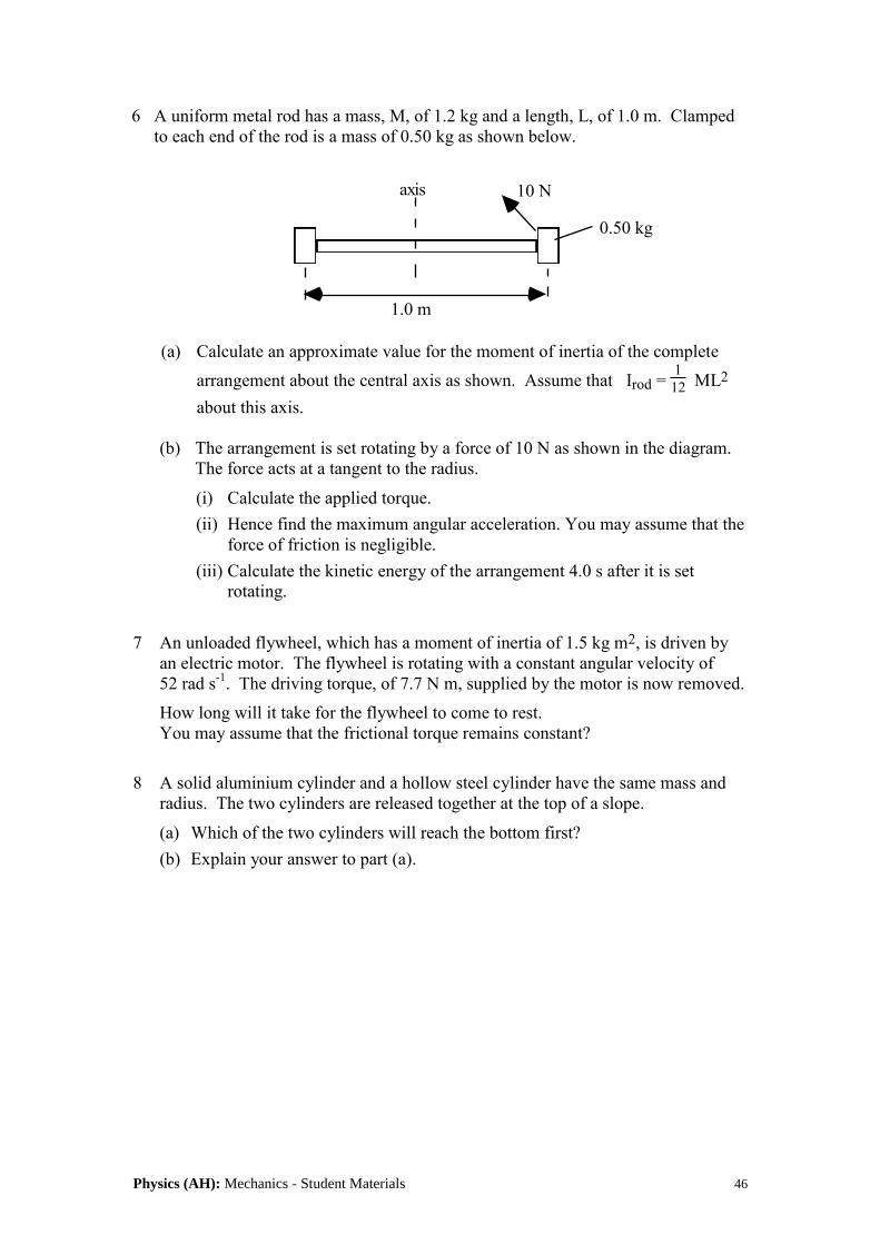
6 A uniform metal rod has a mass, M, of 1.2 kg and a length, L, of 1.0 m. Clamped
to each end of the rod is a mass of 0.50 kg as shown below.
axis
1.0 m
0.50 kg
10 N
(a) Calculate an approximate value for the moment of inertia of the complete
arrangement about the central axis as shown. Assume that Irod = 1
12 ML2
about this axis.
(b) The arrangement is set rotating by a force of 10 N as shown in the diagram.
The force acts at a tangent to the radius.
(i) Calculate the applied torque.
(ii) Hence find the maximum angular acceleration. You may assume that the
force of friction is negligible.
(iii) Calculate the kinetic energy of the arrangement 4.0 s after it is set
rotating.
7 An unloaded flywheel, which has a moment of inertia of 1.5 kg m2, is driven by
an electric motor. The flywheel is rotating with a constant angular velocity of
52 rad s-1
. The driving torque, of 7.7 N m, supplied by the motor is now removed.
How long will it take for the flywheel to come to rest.
You may assume that the frictional torque remains constant?
8 A solid aluminium cylinder and a hollow steel cylinder have the same mass and
radius. The two cylinders are released together at the top of a slope.
(a) Which of the two cylinders will reach the bottom first?
(b) Explain your answer to part (a).

Physics (AH): Mechanics - Student Materials 48
TUTORIAL 5
Gravitation
1 Show that the force of attraction between two large ships of mass 50000 tonnes and
separated by a distance of 20 m is 417 N. (1 tonne = 1000 kg)
2 Calculate the gravitational force of attraction between the proton and the electron in
a hydrogen atom. Assume the electron is describing a circular orbit with a radius
of 5.3 x 10⁻¹¹ m.
(mass of proton = 1.67 x 10⁻²⁷ kg; mass of electron = 9.11 x 10⁻³¹ kg).
3 A satellite, of mass 1500 kg, is moving at constant speed in a circular orbit 160 km
above the Earth's surface.
(a) Calculate the period of rotation of the satellite.
(b) Calculate the total energy of the satellite in this orbit.
(c) Calculate the minimum amount of extra energy required to boost this satellite
into a geostationary orbit which is at a distance of 36 000 km above the Earth's
surface.
4 The planet Mars has a mean radius of 3.4 x 10⁶ m. The Earth's mean radius is
6.4 x 10⁶ m. The mass of Mars is 0.11 times the mass of the Earth.
(a) How does the mean density of Mars compare with that of the Earth?
(b) Calculate the value of "g" on the surface of Mars.
(c) Calculate the escape velocity on Mars.
5 Determine the potential energy between the planet Saturn and its rings.
Assume the rings have a mass of 3.5 x 10¹⁸ kg and are concentrated at an average
distance of 1.1 x 10⁸ m from the centre of Saturn.
The mass of Saturn is 5.72 x 1026 kg.
6 During trial firing of Pioneer Moon rockets, one rocket reached an altitude of
125 000 km.
Neglecting the effect of the Moon, estimate the velocity with which this rocket
struck the atmosphere of the Earth on its return. (Assume that the rocket's path is
entirely radial and that the atmosphere extends to a height of 130 km above the
Earth's surface).
7 (a) Sketch the gravitational field pattern between the Earth and Moon.
(b) Gravity only exerts attractive forces. There should therefore be a position
between the Earth and Moon where there is no gravitational field - a so-called
'null' point.
By considering the forces acting on a mass m placed at this point, calculate
how far this position is from the centre of the Earth.

Physics (AH): Mechanics - Student Materials 52
TUTORIAL 7
Wave-Particle Duality
1 (a) An electron moves with a velocity of 3x10⁶ m s-1. What is its de Broglie
wavelength?
(b) A proton moves with the same velocity. Determine its de Broglie wavelength.
2 An electron is accelerated from rest through a p.d. of 200 V .
(a) Calculate the non-relativistic velocity of this electron.
(b) What is the de Broglie wavelength of this electron?
(c) Would this electron show particle or wave like characteristics on meeting an
obstacle of diameter 1 mm?
3 Calculate the de Broglie wavelength of an electron accelerated through a potential
difference of 20 kV. (This is the p.d. typically used in a colour television tube.)
4 The wave and particle models in physics are related by the expression: = h
p .
(a) State what is meant by each of the symbols in the equation.
(b) Give an illustration in physics where:
(i) photons are said to behave like waves
(ii) photons are said to behave like particles
(iii) electrons are said to behave like waves
(iv) electrons are said to behave like particles.
5 (a) Calculate the wavelength of electrons in an electron microscope which have
been accelerated through a p.d. of 100 kV.
(Use a non relativistic calculation.)
(b) Hence explain why such electrons can be used to examine objects on the
atomic scale.
6 Explain why the wave nature of matter is not more evident in everyday life.
7 Calculate the de Broglie wavelength associated with an athlete of mass 70 kg
running with a speed of 10 m s-1.
8 (a) Using the non-relativistic equations for momentum and kinetic energy, show
that the de Broglie wavelength of an electron accelerated through a p.d. of
V volts can be written as: = 1.23 x 10⁻⁹
V m.
(b) Using the equation in (a) above, calculate the wavelength of electrons which
have been accelerated, from rest, through a potential difference of 1000 V.
(c) Electrons as described in (b) above, are fired at a sample of crystalline
material. A diffraction pattern is observed for the electrons as they pass
through the crystals. State a possible approximate value for the spacing of the
molecules in the crystalline solid.
9 Describe what is meant by saying that the angular momentum of an electron about
the nucleus is quantised.

Physics (AH): Electrical Phenomena - Student Materials 1
ELECTRICAL PHENOMENA – STUDENT MATERIAL
ELECTRICAL FIELDS
Forces between Electric Charges Coulomb's Law (1785)
Forces between electric charges have been observed since earliest times. Thales of
Miletus, a Greek living in around 600 B.C., observed that when a piece of amber was
rubbed, the amber attracted bits of straw.
However it was not until 2500 years later that the forces between charged particles
were actually measured by Coulomb using a torsion balance method. The details of
Coulomb's experiment are interesting but his method is difficult to reproduce in a
teaching laboratory.
Coulomb's Inverse Square Law
Coulomb's experiment gives the following mathematical results:
F 1
r2 and F (Q1 Q2)
Thus F = k 2
21
r
Q Q
Value of k
When other equations are developed from Coulomb's Law, it is found that the product
4k frequently occurs. Thus, to avoid having to write the factor 4in these derived
equations, it is convenient to define a new constant o, called the permittivity of free
space, such that:
o = 1
4k or k =
1
4o where is the Greek letter
'epsilon'
k is approximately 9.0 x 10⁹ N m2 C-2
Equation for Coulomb's inverse square law
F = 1
4o
Q1Q2
r2 when Q1 and Q2 are separated by air
Notes:
• Force is a vector quantity. If more than two charges are present, the force on any
given charge is the vector sum of all the forces acting on that charge.
• Coulomb's law has a similar form as the gravitational force, FG = G m m
r
1 2
2 .
• o was until recently an experimentally determined quantity. However, since 1983
as part of the redefinition of the metre, scientists have defined the value c for the
speed of light: c = 299792458 m s-1 (exact by definition).
In addition, the permeability of free space , which you will meet later in this
unit, is a defined quantity: o = 4 x 10⁻⁷ H m-1 (exact by definition)
These 3 quantities are related by an equation derived by James Clerk Maxwell:
c = 1
oo Thus the exact value of o =
1
c2o = 8.85418781 x 10⁻¹² F m-1.
Physics (AH): Electrical Phenomena - Student Materials 2
Example
Three identical charges A,B and C are fixed at the positions shown in the right angled
triangle below.
0.60 m 0.80 m
0.10 m
90°
A
B C
Each charge is +8 nC (i.e. +8.0 x 10⁻⁹ C) in magnitude.
(a) Calculate the forces exerted on charge A by charges B and C.
(b) Calculate the resultant force on charge A. (This means magnitude and direction)
Solution
(a) FBA = 1
4o
QBQA
r2 = 9 x 109 x 8 x 10 x 8 x 10
(0.6)
-9 -9
2 = 1.6 x 10⁻⁶ N
Direction is along BA, or repulsion.
FCA = 1
4o
QCQA
r2 = 9 x 109 x 8 x 10 x8 x 10
(0.8)
-9 -9
2 = 0.90 x 10⁻⁶ N
Direction is along CA, or repulsion
1.6 x 10⁻⁶
N
90°
0.90 x 10⁻⁶
N
FBA
CAF
90°
0.90 x 10⁻⁶
N
1.6 x 10⁻⁶
N
vector addition
Resultant = FBA2 + FCA
2 = 1.8 x 10⁻⁶ N
tan = 0.9 x 10⁻⁴
1.6 x 10-4 = 0.563 thus = 29°
Resultant force on charge A = 1.8 x 10⁻⁶ N at an angle of 29° as shown above.
The table below contains some atomic data for answering the questions in Tutorial 1.
Particle
Symbol
Charge/C
Mass/kg
Typical
diameter of
atoms/m
Typical
diameter of
nuclei/m
proton p +e
1.60 x 10⁻¹⁹
1.673 x 10⁻²⁷
1 x 10⁻¹⁰
1 x 10-15
neutron n
0
1.675 x 10⁻²⁷
to
to
electron e- -e
-1.60 x 10⁻¹⁹
9.11 x 10⁻³¹
3 x 10⁻¹⁰
7 x 10-15

Physics (AH): Electrical Phenomena - Student Materials 3
For very small distances, for example between nucleons, there is a strong attractive
nuclear force. At distances above 1 x 10-15 m the electrostatic force comes into play.
This is the force which basically binds atoms together. At very large distances the
gravitational force is dominant.
The Electric Field
The idea of a field is a useful way to visualise how charges affect one another.
We say that a charge sets up a field around itself such that it will influence other
charges in that field.
Q-FF
Qt
P
+
Charge Qt placed at point P in the field, set up by charge Q, will experience a force F
due to the field at P. A charged object cannot experience its own electric field.
Definition of an electric field
An electric field is said to be present at a point if a force, of electrical origin, is
exerted on a charge placed at that point.
In the following work on electric fields there are two problems:
• calculating the fields set up by certain charge distributions
• calculating the force experienced by a charge when placed in a known field.
Electric Field Strength
The electric field strength E at any point is the force on unit positive charge placed at
that point.
If a charge Qt, placed at point P in the electric field, experiences a force F then:
E = F
Q t
unit of E: N C-1
Notes
• The direction of E is conventionally taken as the direction in which a positive test
charge would move in the field. Thus for a positive charge, the direction of the
field is away from the charge.
• The charge Qt must be small enough not to alter E.
• The unit N C-1 is equivalent to the unit V m-1, see later.
This is similar to the gravitational field around mass m: g = F
m unit of g: N kg-1.
Electric Field Lines
An electric field line is a convenient concept developed by Michael Faraday to help
the visualisation of an electric field.
Notes
• The tangent to a field line at a point gives the direction of the field at that point.
• Field lines are continuous; they begin on positive charges and end on negative
charges. They cannot cross.

Physics (AH): Electrical Phenomena - Student Materials 4
• If lines are close the electric field strength is strong, if the lines are far apart the
field is weak. If lines are parallel and equally spaced the field is said to be uniform.
• Field lines cut equipotential surfaces at right angles, see later.
Examples of electric field patterns
An isolated positive charge An isolated negative charge
These patterns are called radial fields. The lines are like the radii of a circle.
Two equal but opposite charges
Charged parallel plates
The field lines are parallel and equally
spaced between the plates.
This is called a uniform field.
Equation for Electric Field Strength
Consider placing test charge Qt at a point distance r from a fixed point charge Q in a
vacuum.
The force between the two charges is given by: F = 1
4o QQt
r2
But electric field strength, E is defined as Force
Charge thus E =
FQ t
giving:
E = o4π
1 2r
Q
Notes
• This equation gives the magnitude of the electric field strength around an isolated
point charge; its direction is radial. The electric field strength reduces quickly as
the distance r increases because E 1
r2
• Electric field strength is a vector quantity. When more than one charge is present,
the electric field strength must be calculated for each charge and the vector sum
then determined.
+
+
+
+
+
+
Physics (AH): Electrical Phenomena - Student Materials 5
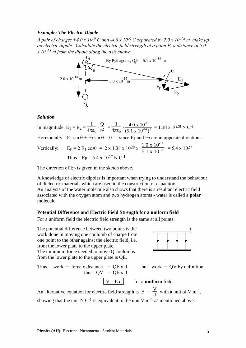
Example: The Electric Dipole
A pair of charges +4.0 x 10⁻⁹ C and -4.0 x 10⁻⁹ C separated by 2.0 x 10⁻¹⁴ m make up
an electric dipole. Calculate the electric field strength at a point P, a distance of 5.0
x 10-14 m from the dipole along the axis shown.
2.0 x 10⁻¹⁴
m
+
-
E
E
1
1 Q
Q 2
2
P
E P
5.0 x 10 -14
m
By Pythagoras, Q P = 5.1 x 10⁻¹⁴
m 1
Solution
In magnitude: E1 = E2 = 1
4o .
Q
r2 = 1
4o . 4.0 x 10
(5.1 x 10 )
-9
-14 2 = 1.38 x 1028 N C-1
Horizontally: E1 sin + E2 sin = 0 since E1 and E2 are in opposite directions.
Vertically: EP = 2 E1 cos = 2 x 1.38 x 1028 x 1.0 x 10
5.1 x 10
-14
-14 = 5.4 x 1027
Thus EP = 5.4 x 1027 N C-1
The direction of EP is given in the sketch above.
A knowledge of electric dipoles is important when trying to understand the behaviour
of dielectric materials which are used in the construction of capacitors.
An analysis of the water molecule also shows that there is a resultant electric field
associated with the oxygen atom and two hydrogen atoms - water is called a polar
molecule.
Potential Difference and Electric Field Strength for a uniform field
For a uniform field the electric field strength is the same at all points.
The potential difference between two points is the
work done in moving one coulomb of charge from
one point to the other against the electric field, i.e.
from the lower plate to the upper plate.
The minimum force needed to move Q coulombs
from the lower plate to the upper plate is QE.
Thus work = force x distance = QE x d. but work = QV by definition
thus QV = QE x d
V = E d for a uniform field.
An alternative equation for electric field strength is E = Vd
with a unit of V m-1,
showing that the unit N C-1 is equivalent to the unit V m-1 as mentioned above.
_
+

Physics (AH): Electrical Phenomena - Student Materials 6
Charging by Induction
A conducting object can be charged by induction by bringing another charged object
close to it. The gold leaf electroscope has a conducting cap connected to a central
metal rod and a thin gold leaf which is able to move. (The electroscope is in effect a
voltmeter - it measures the potential difference between its cap and earth. This is
shown by the angle its leaf makes with the vertical, the bigger the angle the greater the
potential difference.) The electroscope can be used to detect the presence of, and
nature of, charge on both metallic and non-metallic objects.
Charging an electroscope by induction.
The electroscope is first discharged by 'earthing' it. Simply touch it with your finger.
Any excess charge it may have will be neutralised by electrons either flowing to or
from earth through your body. If it has an initial positive charge, when you touch it,
electrons will be attracted from earth, through your body, and neutralise the positive
charge. The following four steps show how an electroscope is charged by induction
to give it a positive charge.
1 Bring up a negative charge close to the
electroscope.
(Usually a white polythene rod rubbed
with a cloth.)
+ + + + +
negatively charged rod
cap
leaf
2 Now earth the cap of the electroscope
with a finger.
+ + + + +
finger
electrons
some electrons are repelled to Earth
3 Now remove your finger
+ + + + +
electrons cannot now return
4 Now remove the rod.
The leaf rises.
+
+
+
+
+some electrons are
attracted from the leaf to
the cap. In this way the
positive charge is
re-distributed.
The electroscope has become positively charged because electrons have been repelled
to earth by the negatively charged rod, that is the electrons have been induced
(persuaded) to move - hence induction.

Physics (AH): Electrical Phenomena - Student Materials 7
Charging two identical metal spheres with equal and opposite charge.
1 Ensure that the two metal spheres are
touching and that they are initially
uncharged.
2 metal spheres
insulated supports
2 Bring up a charged object and hold it
close.
(A rubbed acetate rod carries a positive
charge.)
++
+++
+++
++++
__
___
charge
separation
3 Now separate the spheres first then remove
the charged rod.
++
+ +
+ __
_
__
spheres far
apart
The two spheres must have equal and opposite charges because the positively charged
rod has attracted a number of electrons into the nearest sphere. This leaves the furthest
away sphere with an equal deficiency of electrons, hence positively charged.
Testing the Sign of a Charge
First, charge an electroscope with a known charge, say positive. Rub a plastic object,
e.g. a ruler, comb, pen etc. Now bring this charged object slowly towards the cap of
the electroscope. If the leaf rises further the object is charged positively. If the leaf
goes down, the object is probably charged negatively although care must be taken
because some uncharged (metal) objects can cause the leaf to fall slightly because
charges may be induced on the object's surface.
Faraday's Ice-Pail Experiment
A deep metal can is placed on the
cap of an uncharged gold-leaf
electroscope. A small sphere,
suspended on insulating thread, is
charged positively and suspended
inside the can, without touching
the walls or the base. Note the
deflection of the leaf, figure (i).
Now remove the charged sphere
and note that the leaf deflection
goes back to zero.
Repeat the experiment but this time touch the charged sphere to the bottom of the
can. Note the deflection of the leaf as the sphere touches, figure (ii).

Physics (AH): Electrical Phenomena - Student Materials 8
Take the sphere to an uncharged electroscope and touch the sphere onto the cap. You
should note that there is no charge left on the sphere - it has given up all its charge to
the deep can, figure (iii).
Notes
• When the charged sphere touches the inside of the can, the negative induced charge
on the inside exactly neutralises the positive charge on the sphere. Thus the
induced negative charge is equal and opposite to the charge on the sphere.
• As the sphere has no charge left after touching the bottom of the can, the induced
positive charge must exist entirely on the outside surface of the can.
• When a charge is given to an object, either hollow or solid, that charge will be
found on the outside surface of the object.
Conducting Shapes in Electric Fields
As shown in the Faraday's Ice-Pail Experiment any charge given to a conductor
always resides on the outer surface of the conductor. A direct consequence of this fact
is that the electric field inside a conductor must be zero, that is Einside = 0.
Reasoning
The field must be zero inside the conductor because if it were non-zero any charges
placed inside would accelerate in the field and move until balance was reached again.
This would only be achieved when no net force acted on any of the charges, which in
turn means that the field must be zero. This is also why any excess charge must reside
entirely on the outside of the conductor with no net charge on the inside. Also, the
field outside the conductor must start perpendicular to the surface. If it did not there
would be a component of the field along the surface causing charges to move until
balance was reached.
If an uncharged conductor is placed in an electric field, charges are induced as shown
below so that the internal field is once again zero. Notice that the external field is
modified by the induced charges on the surface of the conductor and that the overall
charge on the conductor is still zero.
uncharged conductor
uniform field
E = 0
+ + + +
+
You can now see why the leaf deflection of a charged gold leaf electroscope can go
down if an uncharged metal object is brought close - the field set up by the charge on
the electroscope causes equal and opposite charges to be induced on the object.
Physics (AH): Electrical Phenomena - Student Materials 9
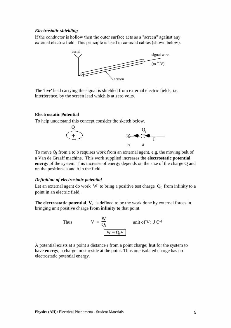
Electrostatic shielding
If the conductor is hollow then the outer surface acts as a "screen" against any
external electric field. This principle is used in co-axial cables (shown below).
aerial
screen
signal wire
(to T.V)
The 'live' lead carrying the signal is shielded from external electric fields, i.e.
interference, by the screen lead which is at zero volts.
Electrostatic Potential
To help understand this concept consider the sketch below.
+
Q
+F
b a
Qt
To move Qt from a to b requires work from an external agent, e.g. the moving belt of
a Van de Graaff machine. This work supplied increases the electrostatic potential
energy of the system. This increase of energy depends on the size of the charge Q and
on the positions a and b in the field.
Definition of electrostatic potential
Let an external agent do work W to bring a positive test charge Qt from infinity to a
point in an electric field.
The electrostatic potential, V, is defined to be the work done by external forces in
bringing unit positive charge from infinity to that point.
Thus V = W
Qt unit of V: J C-1
W = QtV
A potential exists at a point a distance r from a point charge; but for the system to
have energy, a charge must reside at the point. Thus one isolated charge has no
electrostatic potential energy.

Physics (AH): Electrical Phenomena - Student Materials 10
Electrostatic Potential due to a Point Charge
To find the electrostatic potential at a point P a distance r from the charge Q we need
to consider the work done to bring a small test charge Qt from infinity to that point.
The force acting against the charge Qt increases as it comes closer to Q. Calculus is
used to derive the following expression for the electrostatic potential V at a distance r
due to a point charge Q.
V = 1
4o Q
r Thus V
1
r
Notice that the expression for electrostatic potential has a very similar form to that for
gravitational potential: V = - G mr
.
Notes
• Electrostatic potential is a scalar quantity. If a number of charges lie close to one
another the potential at a given point is the scalar sum of all the potentials at that
point. This is unlike the situation with electric field strength. Negative charges
have a negative potential.
• In places where E = 0, V must be a constant at these points. We will see this later
when we consider the field and potential around charged spheres.
Electrostatic Potential Energy
Electrostatic potential at P is given by
V =
If a charge Qt is placed at P
electrostatic potential energy of charge Qt =
electrostatic potential energy of charge Qt = r4π
o
t
A positively charged particle, if free to move in an electric field, will accelerate in the
direction of the field. This means that the charge is moving from a position of high
electrostatic potential energy to a position of lower electrostatic potential energy,
losing electrostatic potential energy as it gains kinetic energy.
The Electronvolt
This is an important unit of energy in high energy particle physics. While it is not
mentioned in the syllabus, it is covered here because of its widespread use.
The electronvolt is the energy acquired when one electron accelerates through a
potential difference of 1 V. This energy, QV, is changed from electrical to kinetic
energy.
1 electronvolt = 1.6 x 10-19 C x 1 V giving 1 eV = 1.6 x 10⁻¹⁹ J.
Often the unit MeV is used; 1 MeV = 1.6 x 10⁻¹³ J.
+Qt
Q P r
vacuum
+ Qt brought from infinity
to point P
+ P
r

Physics (AH): Electrical Phenomena - Student Materials 11
Equipotentials
This idea of potential gives us another way of describing fields.
The first approach was to get values of E, work out the force F on a charge and draw
field lines. A second approach is to get values of V, work out the electrostatic
potential at a point and draw equipotential lines or surfaces.
Equipotential surfaces are surfaces on which the potential is the same at all points;
that is no work is done when moving a test charge between two points on the surface.
This being the case, equipotential surfaces and field lines are at right angles.
The sketches below show the equipotential surfaces (solid lines) and field lines
(broken) for different charge distributions. These diagrams show 2-dimensional
pictures of the field. The field is of course 3-dimensional.
(a) an isolated charge (b) two unlike charges
(c) two like charges
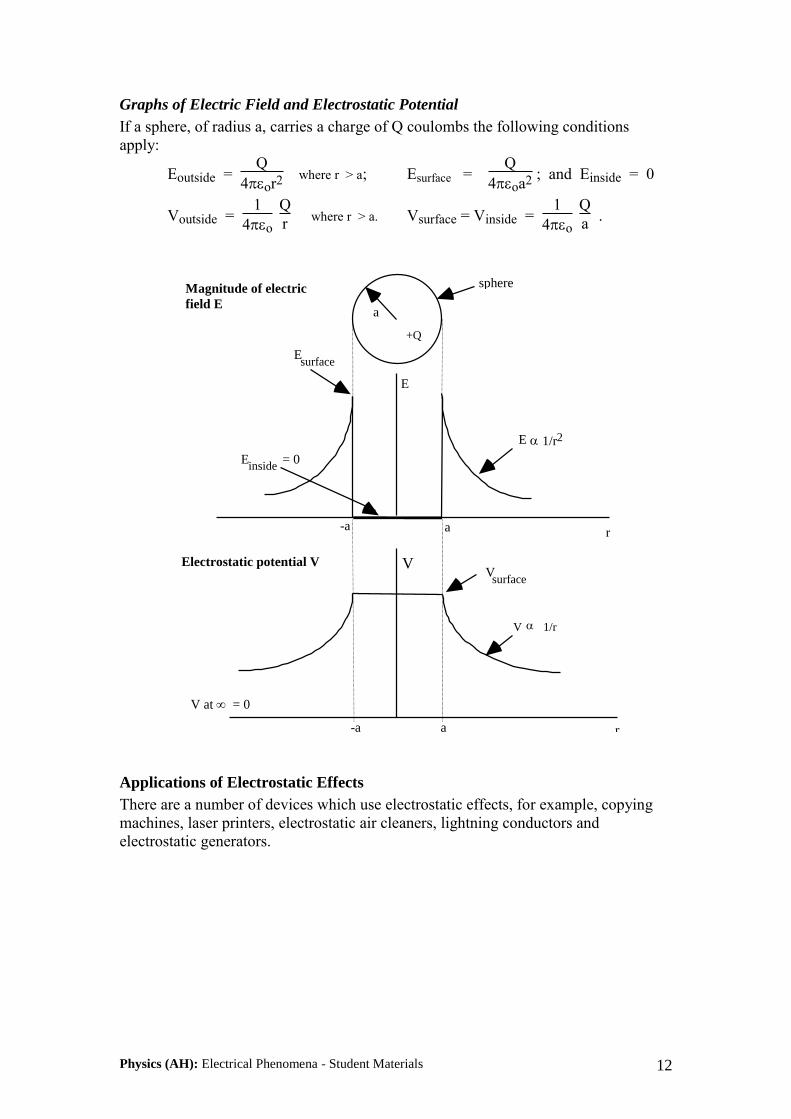
Charged Spheres
For a hollow or solid sphere any excess charge will be found on its outer surface.
The graphs show the variation of both electric field strength and electrostatic potential
with distance for a sphere carrying an excess of positive charge.
The main points to remember are:
• the electric field is zero inside the sphere
• outside the sphere the electric field varies as the inverse square of distance from
sphere; E 1
r2
• the potential has a constant (non-zero) value inside the sphere
• Outside the sphere the potential varies as the inverse of the distance from the
sphere; V 1
r .
Physics (AH): Electrical Phenomena - Student Materials 12
Graphs of Electric Field and Electrostatic Potential
If a sphere, of radius a, carries a charge of Q coulombs the following conditions
apply:
Eoutside = Q
4or2 where r > a; Esurface = Q
4oa2 ; and Einside = 0
Voutside = 1
4o Q
r where r > a. Vsurface = Vinside = 1
4o Q
a .
Electrostatic potential V V
r
V at = 0
V 1/r
a -a
V surface
r
a
a -a
sphere
E
E 1/r 2
+Q
E surface
Magnitude of electric
field E
E = 0 inside
Applications of Electrostatic Effects
There are a number of devices which use electrostatic effects, for example, copying
machines, laser printers, electrostatic air cleaners, lightning conductors and
electrostatic generators.
Physics (AH): Electrical Phenomena - Student Materials 13
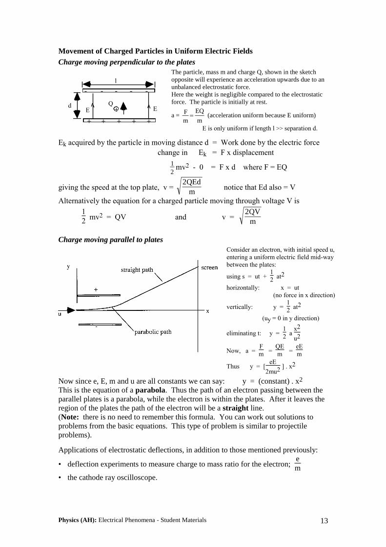
Movement of Charged Particles in Uniform Electric Fields
Charge moving perpendicular to the plates
+
+ + + ++
- - - - -
d
l
QEE
The particle, mass m and charge Q, shown in the sketch
opposite will experience an acceleration upwards due to an
unbalanced electrostatic force.
Here the weight is negligible compared to the electrostatic
force. The particle is initially at rest.
a = m
EQ
m
F (acceleration uniform because E uniform)
E is only uniform if length l >> separation d.
Ek acquired by the particle in moving distance d = Work done by the electric force
change in Ek = F x displacement
1
2mv2 - 0 = F x d where F = EQ
giving the speed at the top plate, v = 2QEd
m notice that Ed also = V
Alternatively the equation for a charged particle moving through voltage V is
1
2 mv2 = QV and v =
2QV
m
Charge moving parallel to plates
Consider an electron, with initial speed u,
entering a uniform electric field mid-way
between the plates:
using s = ut + 1
2 at2
horizontally: x = ut
(no force in x direction)
vertically: y = 1
2 at2
(uy = 0 in y direction)
eliminating t: y = 1
2 a
x2
u2
Now, a = F
m =
QE
m =
eE
m
Thus y = [eE
2mu2 ] . x2
Now since e, E, m and u are all constants we can say: y = (constant) . x2
This is the equation of a parabola. Thus the path of an electron passing between the
parallel plates is a parabola, while the electron is within the plates. After it leaves the
region of the plates the path of the electron will be a straight line.
(Note: there is no need to remember this formula. You can work out solutions to
problems from the basic equations. This type of problem is similar to projectile
problems).
Applications of electrostatic deflections, in addition to those mentioned previously:
• deflection experiments to measure charge to mass ratio for the electron; e
m
• the cathode ray oscilloscope.
Physics (AH): Electrical Phenomena - Student Materials 14
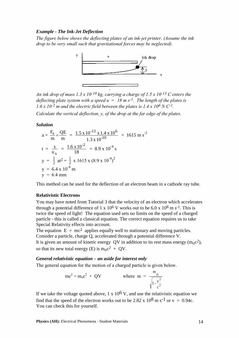
Example - The Ink-Jet Deflection
The figure below shows the deflecting plates of an ink-jet printer. (Assume the ink
drop to be very small such that gravitational forces may be neglected).
An ink drop of mass 1.3 x 10⁻¹⁰ kg, carrying a charge of 1.5 x 10⁻¹³ C enters the
deflecting plate system with a speed u = 18 m s-1. The length of the plates is
1.6 x 10⁻² m and the electric field between the plates is 1.4 x 10⁶ N C-1.
Calculate the vertical deflection, y, of the drop at the far edge of the plates.
Solution
a = m
QE
m
Fe = 10-
6-13
10 x 1.3
10 x 1.4 x 10 x 1.5 = 1615 m s-2
t = xu
x = 18
10 x 1.6 -2 = 8.9 x 10
-4 s
y = 1
2 at2 =
1
2 x 1615 x (8.9 x 10
-4)2
y = 6.4 x 10⁻⁴
m
y = 6.4 mm
This method can be used for the deflection of an electron beam in a cathode ray tube.
Relativistic Electrons
You may have noted from Tutorial 3 that the velocity of an electron which accelerates
through a potential difference of 1 x 10⁶ V works out to be 6.0 x 10⁸ m s-1. This is
twice the speed of light! The equation used sets no limits on the speed of a charged
particle - this is called a classical equation. The correct equation requires us to take
Special Relativity effects into account.
The equation E = mc2 applies equally well to stationary and moving particles.
Consider a particle, charge Q, accelerated through a potential difference V.
It is given an amount of kinetic energy QV in addition to its rest mass energy (moc2),
so that its new total energy (E) is moc2 + QV.
General relativistic equation – an aside for interest only
The general equation for the motion of a charged particle is given below.
mc2 = moc
2 + QV where m =
2
2
c
v - 1
om
If we take the voltage quoted above, 1 x 10⁶ V, and use the relativistic equation we
find that the speed of the electron works out to be 2.82 x 10⁸ m s-1 or v = 0.94c.
You can check this for yourself.

Physics (AH): Electrical Phenomena - Student Materials 15
Note
Relativistic effects must be considered when the velocity of a charged particle is more
than 10% of the velocity of light.
Head-On Collision of Charged Particle with a Nucleus
In the situation where a particle with speed v and positive charge q has a path which
would cause a head-on collision with a nucleus of charge Q, the particle may be
brought to rest before it actually strikes the nucleus.
If we consider the energy changes involved we can estimate the distance of closest
approach of the charged particle.
At closest approach change in Ek of particle = change in Ep of particle.
Position Kinetic energy Electrostatic
potential energy
infinity
1
2mv2
0
closest
approach
+
v = 0
+ + + + +
r Q
q
0
4o 1
r
Change in Ek = 1
2mv2 - 0 =
1
2mv2
Change in electrostatic Ep = qQ
4o 1
r - 0 =
4o 1
r
Change in Ek = change in electrostatic Ep
1
2mv2 =
4o 1
r
and rearranging r = 2qQ
4omv2
Example
Fast moving protons strike a glass screen with a speed of 2.0 x 10⁶ m s-1. Glass is
largely composed of silicon which has an atomic number of 14.
Calculate the closest distance of approach that a proton could make in a head-on
collision with a silicon nucleus.
Solution
Using 1
2 mv2 =
4o .
1
r which gives r =
2qQ
4omv2 and 1
4o = 9.0 x 10⁹
here q = 1.6 x 10⁻¹⁹ C and Q = 14 x 1.6 x 10-19 C (i.e. equivalent of 14 protons)
r = 9.0 x 109 x 2 x 1.6 x 10-19 x 14 x 1.6 x 10-19
1.67 x 10-27 x (2.0 x 106)2
r = 9.7 x 10⁻¹³ m.
v
far from nucleus
+

Physics (AH): Electrical Phenomena - Student Materials 16
Millikan's Oil-Drop Experiment (1910 - 1913)
If possible, view a simulation of this experiment before reading this note.
The charge on the electron was measured by Millikan in an ingenious experiment.
The method involved accurate measurements on charged oil drops moving between
two parallel metal plates, see below.
+
-
d.c.
supply
•
•
• •
• •
•
•
•
•
•
• •
•
•
•
• • • •
oil
drop mg
QE
microscope
oil drops
•
•
•
•
atomiser
Tiny oil drops are charged as they leave the atomiser.
The drops quickly reach a steady speed and an accurate measurement of this speed
allows a value for the radius of the drop to be calculated. From this radius the volume
is found, and using the density of the oil, the mass of the drop is discovered. The drop
can be kept in view by switching on and off the voltage between the plates. For the
polarity shown above, negatively charged oil drops, can be held within the plates.
The second part of each individual experiment involved finding the p.d. needed to
'balance' the oil drop (gravitational force equal and opposite to the electric force).
Therefore mg = QE and E = V
d giving Q =
mgd
V
Analysis of results
Millikan and his assistants experimented on thousands of oil drops and when all these
results were plotted it was obvious that all the charges were multiples of a basic
charge. This was assumed to be the charge on the electron. Single electron charges
were rarely observed and the charge was deduced from the gaps between 'clusters' of
results where Q = ne (n = ±1, ±2, ±3 etc.)
Conclusions
• Any charge must be a multiple of the electronic charge, 1.6 x 10⁻¹⁹ C. Thus we say
that charge is 'quantised', that is it comes in quanta or lumps all the same size.
• It is not possible to have a charge of, say, 2.4 x 10⁻¹⁹ C because this would
involve a fraction of the basic charge.

Physics (AH): Electrical Phenomena - Student Materials 17
ELECTROMAGNETISM
Introduction
Modern electromagnetism as we know it started in 1819 with the discovery by the
Danish scientist Hans Oersted that a current-carrying wire can deflect a compass
needle. Twelve years afterwards, Michael Faraday and Joseph Henry discovered
(independently) that a momentary e.m.f. existed across a circuit when the current in a
nearby circuit was changed. Also it was discovered that moving a magnet towards or
away from a coil produced an e.m.f. across the ends of the coil. Thus the work of
Oersted showed that magnetic effects could be produced by moving electric charges
and the work of Faraday and Henry showed that an e.m.f. could be produced by
moving magnets.
All magnetic phenomena arise from forces between electric charges in motion. Since
electrons are in motion around atomic nuclei, we can expect individual atoms of all
the elements to exhibit magnetic effects and in fact this is the case. In some metals
like iron and nickel these small contributions from atoms can be made to 'line up' and
produce a detectable magnetic property.
The Magnetic Field
As you have seen from gravitational and electrostatics work, the concept of a field is
introduced to deal with 'action-at-a-distance' forces.
Permanent Magnets
It is important to revise the field patterns around some of the combinations of bar
magnet. (You can confirm these patterns using magnets and iron filings to show up
the field lines).
isolated bar magnet opposite poles adjacent
like poles adjacent To establish which end of a bar magnet is the north (N) pole, float the magnet on
cork or polystyrene in a bowl of water and the end which points geographically north
is the 'magnetic north'. Similarly a compass needle, which points correctly towards
geographic north, will point towards the magnetic south pole of a bar magnet. Thus a
compass needle will show the direction of the magnetic field at a point which is
defined to be from magnetic north to south.
Electromagnets
A magnetic field exists around a moving charge in addition to its electric field.
A charged particle moving across a magnetic field will experience a force.
N S N S N S
N S S N

Physics (AH): Electrical Phenomena - Student Materials 18
Magnetic field patterns
A straight wire
Before the current is switched on the compass
needles will point north.
A coil (solenoid)
Notice the almost uniform
field inside the coil.
Left hand grip rule
The direction of the magnetic field, (the magnetic induction, see below) around a wire
is given by the left hand grip rule as shown below.
Sketch Direction (Left Hand Grip
Rule)
Grasp the current carrying wire in
your left hand with your extended left
thumb pointing in the direction of the
electron flow in the wire. Your
fingers now naturally curl round in
the direction of the field lines. Magnetic Induction
The strength of a magnetic field at a point is called the magnetic induction and is
denoted by the letter B. The direction of B at any point is the direction of the
magnetic field at that point.
Definition of the Tesla, the unit of magnetic induction
One tesla (T) is the magnetic induction of a magnetic field in which a conductor of
length one metre, carrying a current of one ampere perpendicular to the field is acted
on by force of one newton.
The magnitude of the force on a current carrying conductor in a magnetic field
The force on a current carrying conductor depends on the magnitude of the current,
the magnetic induction and the length of wire inside the magnetic field. It also
depends on the orientation of the wire to the lines of magnetic field.
F = IlBsin
whereis the angle between the wire
and the direction of the magnetic field
B
I
l
The force is maximum when the current is perpendicular to the magnetic induction.

Physics (AH): Electrical Phenomena - Student Materials 19
The direction of the force on a current carrying conductor in a magnetic field
The direction of the force is perpendicular to the plane containing the wire and the
magnetic induction. When is 90o the force is perpendicular to both the current and
the magnetic induction.
Right hand rule: using the right hand hold the thumb and first two fingers at right
angles to each other. Point the first finger in the direction of the field, the second
finger in the direction of the electron flow, then the thumb gives the direction of the
thrust, or force.
Note: the direction of the force will reverse if the current is reversed.
Example
A wire, which is carrying a current of 6.0 A, has 0.50 m of its length placed in a
magnetic field of magnetic induction 0.20 T. Calculate the size of the force on the
wire if it is placed:
(a) at right angles to the direction of the field,
(b) at 45° to the to the direction of the field and,
(c) along the direction of the field (i.e. lying parallel to the field lines).
Solution
B
I = 6.0 A
l = 0.50 m
(a) F = IlBsin = IlBsin90°
F = 6.0 x 0.50 x 0.20 x 1
F = 0.60 N
(b) F = IlBsin = IlBsin45°
F = 6.0 x 0.5 x 0.20 x 0.707
F = 0.42 N
(c) if = 0° sin = 0 F = 0 N
Magnetic induction at a distance from a long current carrying wire
The magnetic induction around an "infinitely" long current carrying conductor placed
in air can be investigated using a Hall Probe*(see footnote). It is found that the magnetic
induction B varies as I, the current in the wire, and inversely as r, the distance from
the wire.
B = oI
2r where o is the permeability of free space.
o serves a purpose in magnetism very similar to that played by o in electrostatics.
The definition of the ampere fixes the value of o exactly.
*Footnote. A Hall Probe is a device based around a thin slice of n or p-type semiconducting material.
When the semiconducting material is placed in a magnetic field, the charge carriers (electrons and
holes) experience opposite forces which cause them to separate and collect on opposite faces of the
slice. This sets up a potential difference - the Hall Voltage. This Hall Voltage is proportional to the
magnetic induction producing the effect.

Physics (AH): Electrical Phenomena - Student Materials 20
Force per unit length between two parallel wires
Two adjacent current carrying wires will influence one another due to their magnetic
fields.
For wires separated by distance r , the magnetic induction at wire 2 due to the current
in wire 1 is: B1 = oI1
2r
Thus wire 2, carrying current I2 will experience a force:
F12 = I2 l B1 along length l
Substitute for B1 in the above equation:
F12 = I2 l oI1
2r
F
l
= oI1I2
2r
F
l
is known as the force per unit length.
Direction of force between two current carrying wires
Wires carrying current in the same direction will attract.
Wires carrying currents in opposite directions will repel.
This effect can be shown by passing fairly large direct currents through two strips of
aluminium foil separated by a few millimetres. The strips of foil show the attraction
and repulsion more easily if suspended vertically. A car battery could be used as a
supply.
Definition of the Ampere
A current of one ampere is defined as the constant current which, if in two straight
parallel conductors of infinite length placed one metre apart in a vacuum, will
produce a force between the conductors of 2 x 10⁻⁷ newtons per metre.
To confirm this definition apply F
l
= oI1I2
2r to this situation.
1 A
1 A
F
F 1.0 m
Thus I1 and I2 both equal 1 A, r is 1 m and o = 4 x 10⁻⁷ N A-2.
F
l
= 4 x 10-7 x 1 x 1
2 x 1 = 2 x 10⁻⁷ N m-1.
Equally, applying this definition fixes the value of o = 4 x 10⁻⁷ N A-2.
We will see later that the usual unit for o is H m-1
which is equivalent to N A-2.
Physics (AH): Electrical Phenomena - Student Materials 21
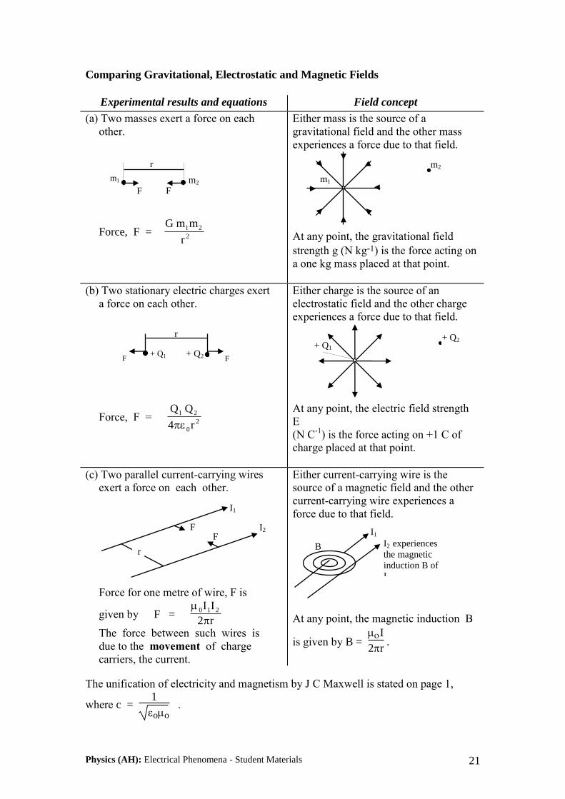
Comparing Gravitational, Electrostatic and Magnetic Fields
Experimental results and equations Field concept
(a) Two masses exert a force on each
other.
Force, F = G m m
r
1 2
2
Either mass is the source of a
gravitational field and the other mass
experiences a force due to that field.
At any point, the gravitational field
strength g (N kg-1) is the force acting on
a one kg mass placed at that point.
(b) Two stationary electric charges exert
a force on each other.
Force, F = Q Q
4 r
1 2
0
2
Either charge is the source of an
electrostatic field and the other charge
experiences a force due to that field.
At any point, the electric field strength
E
(N C-1
) is the force acting on +1 C of
charge placed at that point.
(c) Two parallel current-carrying wires
exert a force on each other.
Force for one metre of wire, F is
given by F = I I
2 r
0 1 2
The force between such wires is
due to the movement of charge
carriers, the current.
Either current-carrying wire is the
source of a magnetic field and the other
current-carrying wire experiences a
force due to that field.
At any point, the magnetic induction B
is given by B = I
2r .
The unification of electricity and magnetism by J C Maxwell is stated on page 1,
where c = 1
oo .
F F
r
I1
I2 I1
B I2 experiences
the magnetic
induction B of
I1
r
F F
m1 m2 m1
m2
+ Q1 + Q2
+ Q2 F + Q1
r
F

Physics (AH): Electrical Phenomena - Student Materials 22
MOTION IN A MAGNETIC FIELD
Magnetic Force on Moving Charges
As mentioned previously, the force on a wire is due to the effect that the magnetic
field has on the individual charge carriers in the wire. We will now consider magnetic
forces on charges which are free to move through regions of space where magnetic
fields exist.
Consider a charge q moving with a constant speed v perpendicular to a magnetic
field of magnetic induction B.
We know that F = IlBsin
Consider the charge q moving through a distance l. (The italic l is used to avoid
confusion with the number one.)
Then time taken t = lv
and current I = t
q =
l
qv giving l I = qv.
Substituting into F = IlBsin with sin = 1 since = 90o, gives:
F = qvB
The direction of the force is given by the same right hand rule mentioned for the
force on a current carrying conductor. You should be able to state the direction of the
force for both positive and negative charges.
Note: If the charge q is not moving perpendicular to the field then the component of
the velocity v perpendicular to the field must be used in the above equation.
Motion of Charged Particles in a Magnetic Field
The direction of the force on a charged particle in a magnetic field is perpendicular to
the plane containing the velocity v and magnetic induction B. The magnitude of the
force will vary if the angle between the velocity vector and B changes. The examples
below illustrate some of the possible paths of a charged particle in a magnetic field.
Charge moving parallel or antiparallel to the magnetic field
The angle between the velocity vector and the magnetic field direction is zero hence
the force F = 0. The path is a straight line.
The direction of the charged particle is not altered.
v
B
charge q moving with velocity v
B
v

Physics (AH): Electrical Phenomena - Student Materials 23
Charge moving perpendicular to the magnetic field
If the direction of v is perpendicular to B, then = 90° and sin = 1.
F = qvB
The direction of the force F is perpendicular to the plane containing v and B.
A particle travelling at constant speed under the action of a force at right angles to its
path will move in a circle. This central force is studied in the Mechanics unit.
The sketch below shows this situation. (Remember an X indicates that the direction
of the field is 'going away' from you 'into the paper'.)
The charged particle will move in a circle, of radius r. The magnetic force supplies
the central acceleration, and maintains the circular motion. Thus: qvB =
mv2
r giving the radius r =
mvqB
The frequency of the rotation can be determined using angular velocity = v
r and
= 2f and substituting in the above equation, giving f = qB
2 m.
Charge moving at an angle to the magnetic field
If the velocity vector v makes an angle with B, the particle moves in a helix
(spiral), the axis of which is parallel to B.
The spiral is obtained from the sum of
two motions:
a uniform circular motion, with a
constant speed v sin in a plane
perpendicular to the direction of B.
a uniform speed of magnitude v cos
along the direction of B
The frequency of the rotation is f = qB
2 m giving the period T =
2 mqB
, the time
between similar points. The pitch p of the helix, shown on the sketch, is the distance
between two points after one period and is given by p = v cos T .
+q
v
r
F
X
X
X X
X X
X
X
X X
X X
X X X
X X X X X

Physics (AH): Electrical Phenomena - Student Materials 24
Notes
• The orbit frequency does not depend on the speed v or radius r. It is dependent
on the charge to mass ratio ( q
m ) and the magnetic induction B.
• Positive charges will orbit in the opposite sense to negative charges, force F
reversed.
• Particles, having the same charge but different masses, e.g. electrons and protons,
entering the magnetic field along the same line will have different radii of orbit.
• The kinetic energy of the particle in orbit is a constant because its orbital speed is
constant. The magnetic force does no work on the charges.
Deflections of charged particles in a bubble chamber
The diagram below is a sketch of a photograph taken in a bubble chamber in which
there is a strong magnetic field. The detecting medium is liquid hydrogen. The
ionisation associated with fast moving charged particles leaves a track of hydrogen
gas (bubbles). The magnetic field is perpendicular to the container. This allows
positive and negative particles to separate and be measured more easily.
The tracks of two particles
in a bubble chamber, one
electron and one positron
are created by an incoming
gamma ray photon, .
Notice the nature and
directions of the
deflections.
As the particles lose
energy their speed
decreases and the radius
decreases.
Note: Problems involving calculations on the motion of charged particles in
magnetic fields will involve non-relativistic velocities only. Although in many
practical applications electrons do travel at high velocities, these situations
will not be assessed.

Physics (AH): Electrical Phenomena - Student Materials 25
Applications of Electromagnetism
- for interest only but these applications can be used for contexts in examination questions
When electric and magnetic fields are combined in certain ways many useful devices
and measurements can be devised.
The Cyclotron
This device accelerates charged particles such as protons and deuterons. Scientists
have discovered a great deal about the structure of matter by examining high energy
collisions of such charged particles with atomic nuclei.
The cyclotron comprises two
semi-circular d-shaped structures
('dees').
There is a gap between the dees
across which there is an
alternating voltage.
Towards the outer rim there is an
exit hole through which the
particle can escape; radius = R.
From this point the particle is
directed towards the target.
Charged particles are generated at the source S and allowed to enter the cyclotron.
Every time an ion crosses the gap between the dees it gains energy, qV, due to the
alternating voltage. For this to happen in step, the frequency of the a.c. must be the
same as the cyclotron frequency, f.
f = qB
2m and r =
mv
qB
Thus, radius increases as velocity increases. At R, velocity will be a maximum.
vmax = qBR
m and Ek on exit =
1
2 mv2 = q2B2R2
2m
The Velocity Selector and Mass Spectrometer
Charged particles can be admitted to a region of space where electric and magnetic
fields are 'crossed', i.e. mutually perpendicular. Particles can only exit via a small slit
as shown below.
Magnetic field is uniform and is
directed 'into the paper'.
Electric field, E = V
d
Electric deflecting force, Fe = qE
Beyond the exit slit, the particles
only experience a magnetic field.
Magnetic force, Fm = qvB and its direction is as shown.
If particle is undeflected; Fm = Fe (in magnitude) thus qvB = qE and v = EB
.
Hence only charges with this specific velocity will be selected. Note that this
expression is independent of q and m. Thus this device will select all charged
particles which have this velocity.
Physics (AH): Electrical Phenomena - Student Materials 26
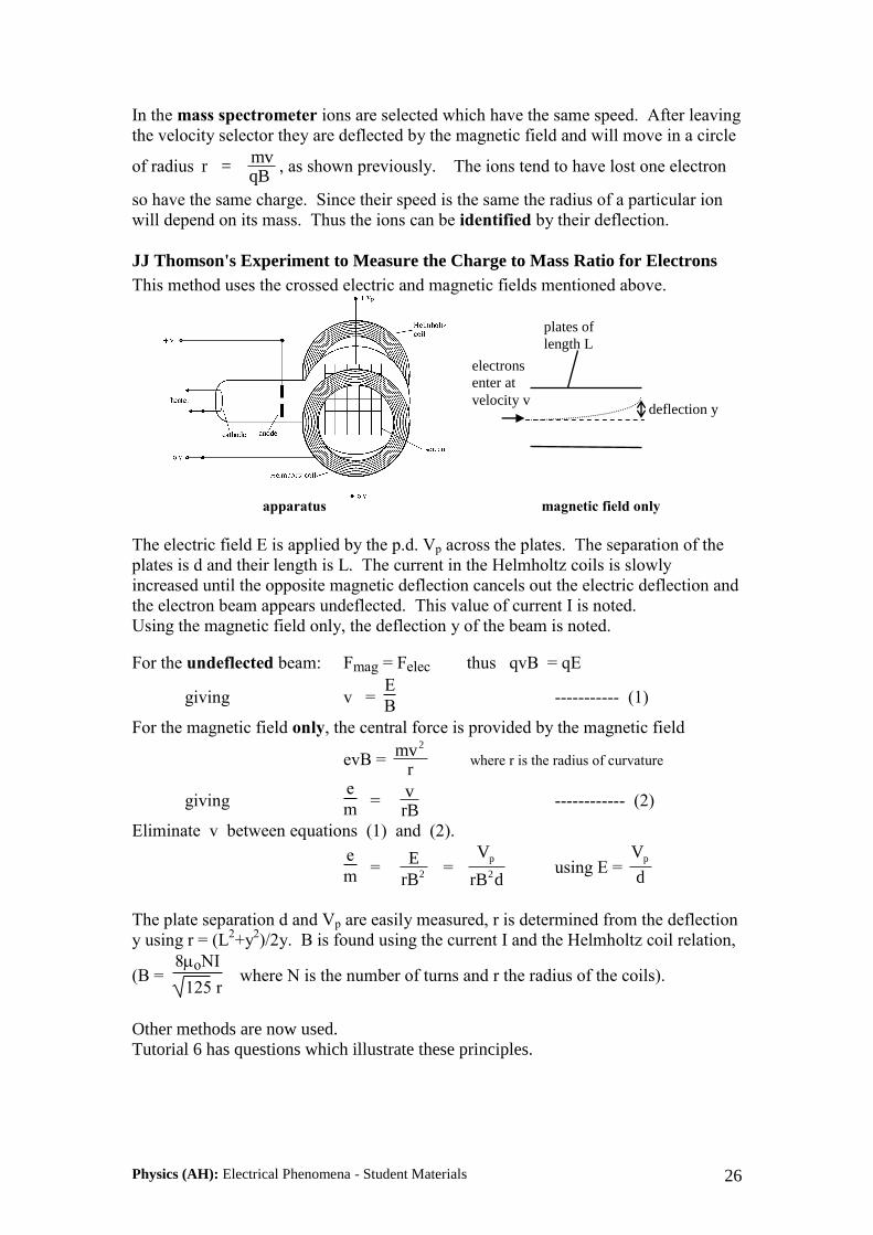
In the mass spectrometer ions are selected which have the same speed. After leaving
the velocity selector they are deflected by the magnetic field and will move in a circle
of radius r = mvqB
, as shown previously. The ions tend to have lost one electron
so have the same charge. Since their speed is the same the radius of a particular ion
will depend on its mass. Thus the ions can be identified by their deflection.
JJ Thomson's Experiment to Measure the Charge to Mass Ratio for Electrons
This method uses the crossed electric and magnetic fields mentioned above.
apparatus
magnetic field only
The electric field E is applied by the p.d. Vp across the plates. The separation of the
plates is d and their length is L. The current in the Helmholtz coils is slowly
increased until the opposite magnetic deflection cancels out the electric deflection and
the electron beam appears undeflected. This value of current I is noted.
Using the magnetic field only, the deflection y of the beam is noted.
For the undeflected beam: Fmag = Felec thus qvB = qE
giving v = E
B ----------- (1)
For the magnetic field only, the central force is provided by the magnetic field
evB = mv
r
2
where r is the radius of curvature
giving e
m =
vrB
------------ (2)
Eliminate v between equations (1) and (2).
e
m =
E
rB 2 =
V
rB d
p
2 using E = V
d
p
The plate separation d and Vp are easily measured, r is determined from the deflection
y using r = (L2+y
2)/2y. B is found using the current I and the Helmholtz coil relation,
(B = 8oNI
125 r where N is the number of turns and r the radius of the coils).
Other methods are now used.
Tutorial 6 has questions which illustrate these principles.
plates of
length L
electrons
enter at
velocity v deflection y
Physics (AH): Electrical Phenomena - Student Materials 27
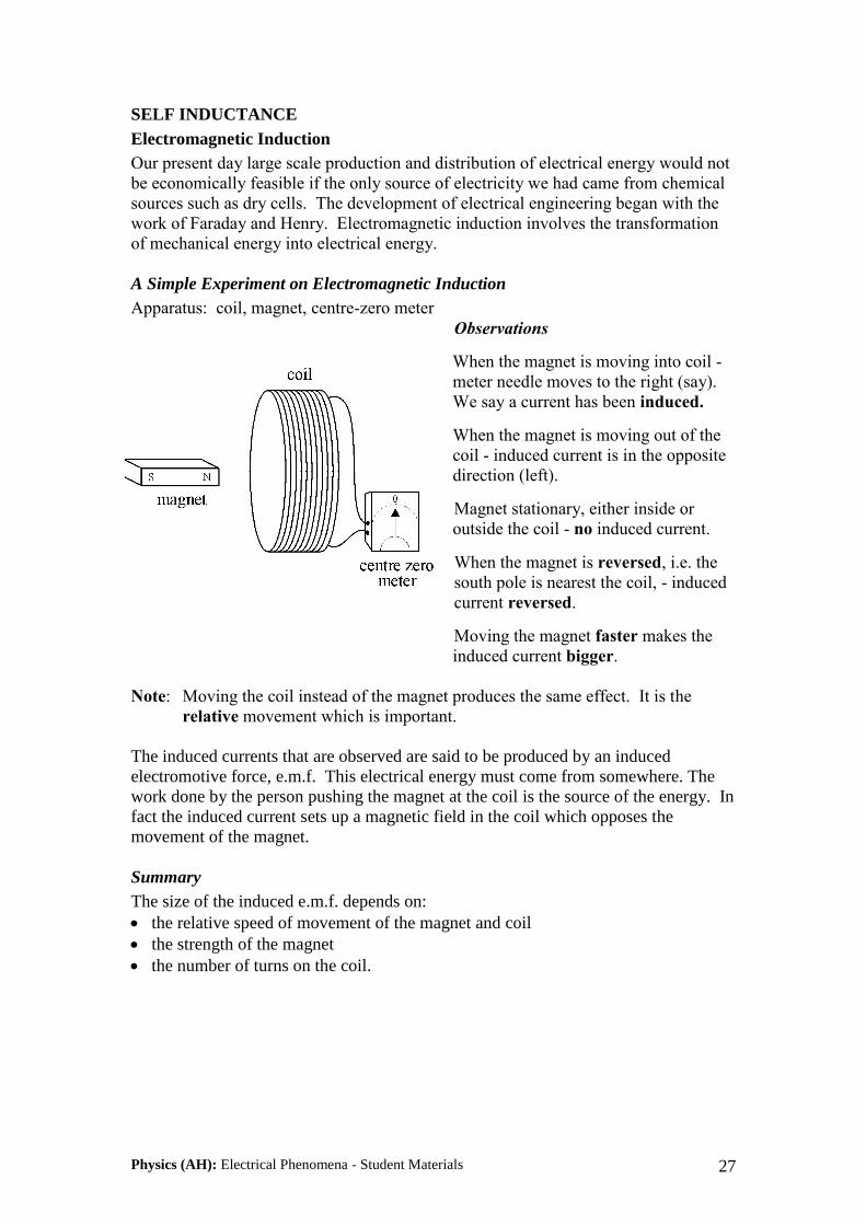
SELF INDUCTANCE
Electromagnetic Induction
Our present day large scale production and distribution of electrical energy would not
be economically feasible if the only source of electricity we had came from chemical
sources such as dry cells. The development of electrical engineering began with the
work of Faraday and Henry. Electromagnetic induction involves the transformation
of mechanical energy into electrical energy.
A Simple Experiment on Electromagnetic Induction
Apparatus: coil, magnet, centre-zero meter
Observations
When the magnet is moving into coil -
meter needle moves to the right (say).
We say a current has been induced.
When the magnet is moving out of the
coil - induced current is in the opposite
direction (left).
Magnet stationary, either inside or
outside the coil - no induced current.
When the magnet is reversed, i.e. the
south pole is nearest the coil, - induced
current reversed.
Moving the magnet faster makes the
induced current bigger.
Note: Moving the coil instead of the magnet produces the same effect. It is the
relative movement which is important.
The induced currents that are observed are said to be produced by an induced
electromotive force, e.m.f. This electrical energy must come from somewhere. The
work done by the person pushing the magnet at the coil is the source of the energy. In
fact the induced current sets up a magnetic field in the coil which opposes the
movement of the magnet.
Summary
The size of the induced e.m.f. depends on:
the relative speed of movement of the magnet and coil
the strength of the magnet
the number of turns on the coil.
Physics (AH): Electrical Phenomena - Student Materials 28
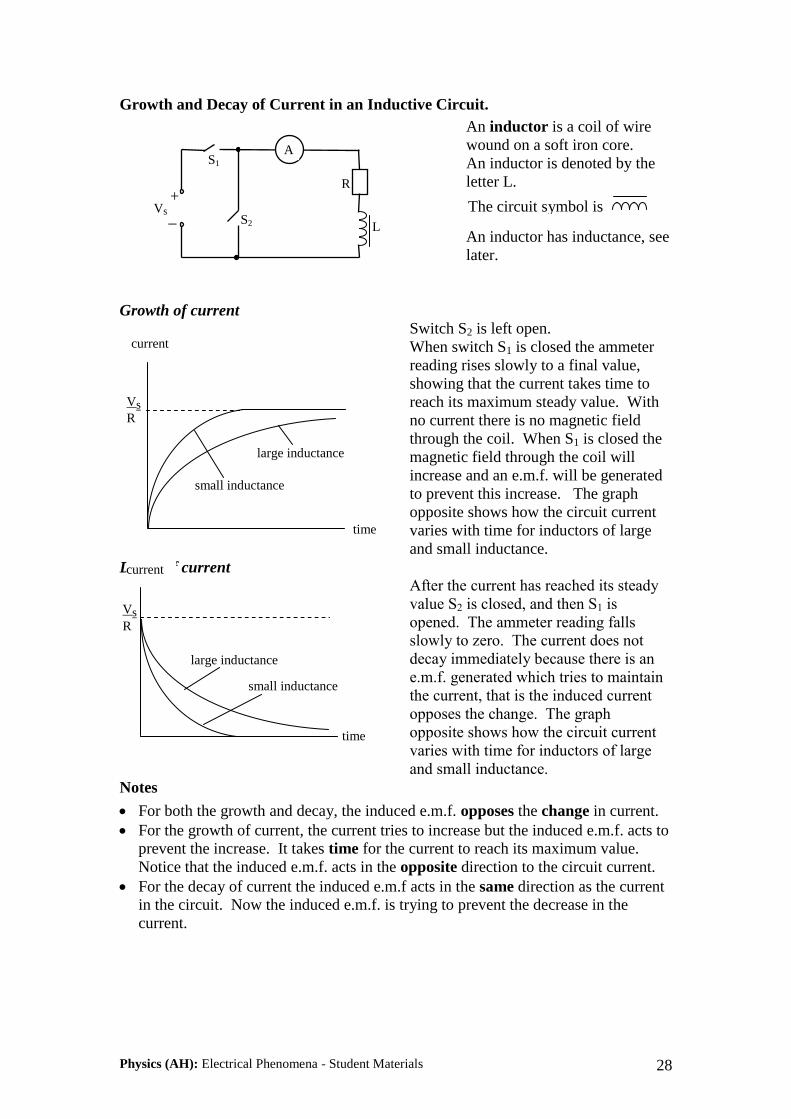
Vs
Growth and Decay of Current in an Inductive Circuit.
An inductor is a coil of wire
wound on a soft iron core.
An inductor is denoted by the
letter L.
An inductor has inductance, see
later.
Growth of current
Switch S2 is left open.
When switch S1 is closed the ammeter
reading rises slowly to a final value,
showing that the current takes time to
reach its maximum steady value. With
no current there is no magnetic field
through the coil. When S1 is closed the
magnetic field through the coil will
increase and an e.m.f. will be generated
to prevent this increase. The graph
opposite shows how the circuit current
varies with time for inductors of large
and small inductance.
Decay of current
After the current has reached its steady
value S2 is closed, and then S1 is
opened. The ammeter reading falls
slowly to zero. The current does not
decay immediately because there is an
e.m.f. generated which tries to maintain
the current, that is the induced current
opposes the change. The graph
opposite shows how the circuit current
varies with time for inductors of large
and small inductance.
Notes
For both the growth and decay, the induced e.m.f. opposes the change in current.
For the growth of current, the current tries to increase but the induced e.m.f. acts to
prevent the increase. It takes time for the current to reach its maximum value.
Notice that the induced e.m.f. acts in the opposite direction to the circuit current.
For the decay of current the induced e.m.f acts in the same direction as the current
in the circuit. Now the induced e.m.f. is trying to prevent the decrease in the
current.
The circuit symbol is
Vs
R
large inductance
small inductance
time
current
R
S2
S1
_
+
L
A
time
large inductance
small inductance
current
Vs
R

Physics (AH): Electrical Phenomena - Student Materials 29
Experiment to show build up current in an inductive circuit
The switch is closed and the variable
resistor adjusted until the lamps B1
and B2 have the same brightness.
The supply is switched off.
The supply is switched on again and
the brightness of the lamps observed.
Lamp B2 lights up immediately. There is a time lag before lamp B1 reaches its
maximum brightness. An e.m.f. is induced in the coil because the current in the coil
is changing. This induced e.m.f. opposes the change in current, and it is called a back
e.m.f. It acts against the increase in current, hence the time lag.
The experiment is repeated with an inductor of more turns. Lamp B1 takes longer to
light fully. If the core is removed from the inductor, lamp B1 will light more quickly.
Induced e.m.f. when the current in a circuit is switched off
When the current in a circuit, containing an inductor, is switched off the magnetic
field through the inductor will fall very rapidly to zero. There will be a large change
in the magnetic field leading to a large induced e.m.f. For example a car ignition coil
produces a high e.m.f. for a short time when the circuit is broken.
Lighting a neon lamp
The 1.5 V supply in the circuit below is insufficient to light the neon lamp. A neon
lamp needs about 80 V across it before it will light.
The switch is closed and the
current builds up to its maximum
value. When the switch is
opened, the current rapidly falls
to zero. The magnetic field
through the inductor collapses
(changes) to zero producing a
very large induced e.m.f. for a
short time. The lamp will flash.
Self inductance
A current in a coil sets up a magnetic field through and round the coil. When the
current in the coil changes the magnetic field changes. A changing magnetic field
induces an e.m.f across the coil. This is called a self induced e.m.f. because the coil is
inducing an e.m.f. in itself due to its own changing current.
The coil, or inductor as it is called, is said to have the property of inductance, L.
The inductance of an inductor depends on its design. Inductance is a property of the
device itself, like resistance of a resistor or capacitance of a capacitor. An inductor
will tend to have a large inductance if it has many turns of wire, a large area and is
wound on an iron core.
R
S
_
+
B2
L
B1
1.5 V
Physics (AH): Electrical Phenomena - Student Materials 30
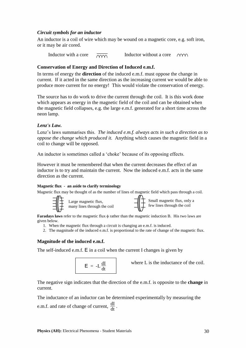
Circuit symbols for an inductor
An inductor is a coil of wire which may be wound on a magnetic core, e.g. soft iron,
or it may be air cored.
Inductor with a core Inductor without a core
Conservation of Energy and Direction of Induced e.m.f.
In terms of energy the direction of the induced e.m.f. must oppose the change in
current. If it acted in the same direction as the increasing current we would be able to
produce more current for no energy! This would violate the conservation of energy.
The source has to do work to drive the current through the coil. It is this work done
which appears as energy in the magnetic field of the coil and can be obtained when
the magnetic field collapses, e.g. the large e.m.f. generated for a short time across the
neon lamp.
Lenz's Law.
Lenz’s laws summarises this. The induced e.m.f. always acts in such a direction as to
oppose the change which produced it. Anything which causes the magnetic field in a
coil to change will be opposed.
An inductor is sometimes called a ‘choke’ because of its opposing effects.
However it must be remembered that when the current decreases the effect of an
inductor is to try and maintain the current. Now the induced e.m.f. acts in the same
direction as the current.
Magnetic flux - an aside to clarify terminology
Magnetic flux may be thought of as the number of lines of magnetic field which pass through a coil.
Faradays laws refer to the magnetic flux rather than the magnetic induction B. His two laws are
given below.
1. When the magnetic flux through a circuit is changing an e.m.f. is induced.
2. The magnitude of the induced e.m.f. is proportional to the rate of change of the magnetic flux.
Magnitude of the induced e.m.f.
The self-induced e.m.f. E in a coil when the current I changes is given by
E = -LdIdt
where L is the inductance of the coil.
The negative sign indicates that the direction of the e.m.f. is opposite to the change in
current.
The inductance of an inductor can be determined experimentally by measuring the
e.m.f. and rate of change of current, dIdt
.
Large magnetic flux,
many lines through the coil
Small magnetic flux, only a
few lines through the coil

Physics (AH): Electrical Phenomena - Student Materials 31
Definition of Inductance
The inductance L of an inductor is one henry (H) when an e.m.f. of one volt is
induced across the ends of the inductor when the current in the inductor changes at a
rate of one ampere per second.
A comment on units
The unit for permeability o was stated to be N A-2
with a usual unit of H m-1
. From
the above formula, in terms of units, we can see that the e.m.f (joules per coulomb)
J C-1
= H A s-1
which is N m (A s)-1
= H A s-1
giving N m A-1
s-1
= H A s-1
and N A-2
= H m-1
(the s-1
cancels)
Energy stored by an Inductor
In situations where the current in an inductor is suddenly switched off large e.m.f.s are
produced and can cause sparks. At the moment of switch off the change in current is
very large. The inductor tries to maintain the current as the magnetic field collapses
and the energy stored by the magnetic field is given up. A magnetic field can be a
source of energy. To set up the magnetic field work must have been done.
Equation for the energy stored in an inductor
For an inductor with a current I the energy stored is given by the equation below:
Energy = 12
L I2
where L is the inductance of the inductor and I the steady current.
Example
An inductor is connected to a 6.0 V direct supply which has a negligible internal
resistance. The inductor has a resistance of 0.8 . When the circuit is switched on it
is observed that the current increases gradually. The rate of growth of the current is
200 A s-1 when the current in the circuit is 4.0 A.
(a) Calculate the induced e.m.f. across the coil when the current is 4.0 A.
(b) Hence calculate the inductance of the coil.
(c) Calculate the energy stored in the inductor when the current is 4.0 A.
(d) (i) When is the energy stored by the inductor a maximum?
(ii) What value does the current have at this time?
Solution
(a) Potential difference across the resistive element of the circuit V = I R
= 4 x 0.8 = 3.2 V
Thus p.d. across the inductor = 6.0 - 3.2 = 2.8 V
L
resistance of inductor
0.8
_
+ 6 V
Physics (AH): Electrical Phenomena - Student Materials 32
(b) Using E = - L dI
dt gives L =
2.8
200 = 0.014 H = 14 mH
(c) Using E = 1
2 L I2 = 0.5 x 0.014 x 4 x 4 = 0.11 J
(d) (i) The energy will be a maximum when the current reaches a steady value.
(ii) Imax = e.m.f
R =
6.0
0.8 = 7.5 A
Inductors in a.c. circuits
In an a.c. circuit the current is continually changing. This means that the magnetic
field through the inductor is continually changing. Hence an e.m.f. is continually
induced in the coil.
Consider the applied alternating voltage at the point in the cycle when the voltage is
zero. As the current tries to increase the induced e.m.f. will oppose this increase.
Later in the cycle as the voltage decreases the current will try to fall but the induced
e.m.f. will oppose the fall. The induced e.m.f. produced by the inductor will
continually oppose the current.
If the frequency of the applied voltage is increased then the rate of change of current
increases. The magnitude of the induced e.m.f. will also increase. Hence there should
be a greater opposition to the current at a higher frequency.
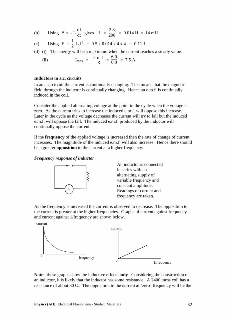
Frequency response of inductor
An inductor is connected
in series with an
alternating supply of
variable frequency and
constant amplitude.
Readings of current and
frequency are taken.
As the frequency is increased the current is observed to decrease. The opposition to
the current is greater at the higher frequencies. Graphs of current against frequency
and current against 1/frequency are shown below.
Note: these graphs show the inductive effects only. Considering the construction of
an inductor, it is likely that the inductor has some resistance. A 2400 turns coil has a
resistance of about 80 . The opposition to the current at ‘zero’ frequency will be the
0
current
1/frequency
A
0
current
frequency

Physics (AH): Electrical Phenomena - Student Materials 33
resistance of the inductor. In practice if readings were taken at low frequencies, the
current measured would be a mixture of the inductive and resistive effects.
An inductor can be used to block a.c. signals while transmitting d.c. signals, because
the inductor produces large induced e.m.f.s at high frequencies.
For a capacitor in an a.c. circuit the current increases when the frequency increases.
The inductor has the opposite effect to a capacitor.
Reactance
The reactance of a capacitor or an inductor is its opposition to alternating current.
The resistance of a resistor is given by R = VI
.
The reactance of an inductor or capacitor is given by X = VI
(XL or XC respectively).
The opposition of a capacitor, the capacitive reactance, decreases as the frequency
increases. At high frequencies there is a greater transfer of charge per second on and
off the capacitor plates. For an inductor, the inductive reactance increases with
frequency. At higher frequencies there is a larger induced e.m.f. opposing the current.
Note: In inductive and capacitive circuits reactances and resistance cannot be added.
Uses of inductors and capacitors in a.c. circuits
The circuit below shows a capacitor and inductor in series with an alternating supply.
At low frequencies the opposition to the current by the inductor is low, so the p.d
across L will be low. At low frequencies the opposition to the current by the capacitor
is high so the p.d. across C will be high. At low frequencies XL<XC.
At high frequencies, the reverse is the case. The p.d. across the inductor VL will be
the higher than the p.d. across the capacitor. At high frequencies XL>XC.
This circuit could be used to filter high and low frequency signals.
L
C
VL
VC

Physics (AH): Electrical Phenomena - Student Materials 34
The transformer - this discussion is for interest only
The principle of operation of the transformer can be given in terms of induced e.m.f.
When S is closed, the meter needle
‘kicks’ momentarily then returns to
zero. When the current is steady the
meter reads zero. When S is opened,
the meter needle kicks briefly in the
opposite direction and returns to zero.
A changing magnetic field is
produced in the coil when the current
changes. This changing magnetic
field will produce an induced e.m.f.
during this short time. However when
the current is steady, there is no
changing field hence no induced e.m.f.
With an a.c. supply the current is
continually changing. This sets up a
continually changing magnetic field
in the soft iron core. Hence an
induced e.m.f. is produced in the
secondary coil.
From the conservation of energy the
direction of the induced e.m.f. will
oppose the change which sets it up.
Hence the direction of a current in
the secondary, at any time, will
always be in the opposite direction to
the current in the primary.
We can now understand why a transformer only operates with an alternating supply.
The transformer is an example of mutual inductance.
S
centre zero
meter primary
coil secondary
coil
d.c.
supply
soft iron
core
S
a.c.
ammeter primary
coil secondary
coil
a.c.
supply
soft iron
core

Physics (AH): Electrical Phenomena - Student Materials 35
THE FUNDAMENTAL FORCES OF NATURE
Forces of nature
The four forces of nature are: • gravitational • electromagnetic • strong • weak.
We find that the gravitational force is by far the weakest of the forces and requires
large masses to produce significant forces. The so-called 'weak' force is only weak in
relation to the 'strong' nuclear force which binds nuclei together.
The electromagnetic force includes both the electrostatic force and the magnetic
force between moving charges. The electrostatic force is an important force between
charged particles outwith the nucleus. Thus atoms are held together by this 'Coulomb'
force where the positive nuclei exert an attractive force on negative electrons. A
typical separation of the nucleus and electrons is 1 x 10⁻¹⁰ m.
The strong nuclear force
Inside nuclei there is a much stronger, short range force which holds the nucleons
together in the nucleus. The strong nuclear force is an attractive force between two
nucleons, either between two protons or two neutrons or one proton and one neutron.
The electrostatic force between two protons repels them apart, but over short nuclear
distances the strong nuclear force is much greater. Hence the protons in a nucleus are
held together with the neutrons. Nuclear diameters are around 10-14 m.
The range for the strong nuclear force is less than 10-14 m.
Protons and neutrons are composed of different kinds of quarks. Each nucleon is
made up of 3 quarks which have the unexpected property of having charges which are
a fraction of the charge on an electron, (e = 1.6 x 10⁻¹⁹ C). Theory suggests that
protons are composed of two up quarks and one down quark, the up quark having
charge of +2
3 e and the down quark -
1
3 e. The neutron is composed of one up quark
and two down quarks giving a charge of zero. Quarks appear to be 'point-like' having
a size less than 1 x 10-18 m. A total of six quarks have been observed, their names, or
flavours, being: up, down, strange, charm, bottom and top. The strong force is
assumed to be a quark-quark force which increases as their separation increases. A
useful analogy is that quarks act as if tied together with indestructible rubber bands.
Certainly single free quarks have not been observed in any experiments so far and
perhaps never will. For a fuller account of quarks and the nature of the strong force
see 'The Cosmic Onion' by Frank Close.
The weak nuclear force
The weak nuclear force is associated with beta radioactive decay in which a neutron
decays to a proton, an electron (and an associated anti-neutrino eν see later).
1
0 n -->
1
1 p +
0
-1 e + eν
The weak force can change the flavour of a quark. In beta decay a down quark is
changed into an up quark. The range of the weak force is less than 10-17 m.
Free neutrons decay, with a half-life of about 14 minutes, by beta emission.
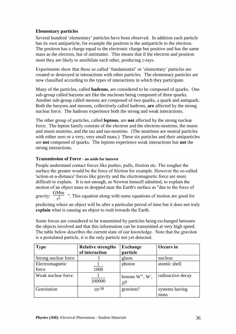
Physics (AH): Electrical Phenomena - Student Materials 36
Elementary particles
Several hundred ‘elementary’ particles have been observed. In addition each particle
has its own antiparticle, for example the positron is the antiparticle to the electron.
The positron has a charge equal to the electronic charge but positive and has the same
mass as the electron, but of antimatter. This means that if the electron and positron
meet they are likely to annihilate each other, producing -rays.
Experiments show that these so called ‘fundamental’ or ‘elementary’ particles are
created or destroyed in interactions with other particles. The elementary particles are
now classified according to the types of interactions in which they participate.
Many of the particles, called hadrons, are considered to be composed of quarks. One
sub-group called baryons are like the nucleons being composed of three quarks.
Another sub-group called mesons are composed of two quarks, a quark and antiquark.
Both the baryons and mesons, collectively called hadrons, are affected by the strong
nuclear force. The hadrons experience both the strong and weak interactions.
The other group of particles, called leptons, are not affected by the strong nuclear
force. The lepton family consists of the electron and the electron-neutrino, the muon
and muon neutrino, and the tau and tau-neutrino. (The neutrinos are neutral particles
with either zero or a very, very small mass.) These six particles and their antiparticles
are not composed of quarks. The leptons experience weak interactions but not the
strong interactions.
Transmission of Force - an aside for interest
People understand contact forces like pushes, pulls, friction etc. The rougher the
surface the greater would be the force of friction for example. However the so-called
'action-at-a-distance' forces like gravity and the electromagnetic force are more
difficult to explain. It is not enough, as Newton himself admitted, to explain the
motion of an object mass m dropped near the Earth's surface as "due to the force of
gravity: GMm
r2 ". This equation along with some equations of motion are good for
predicting where an object will be after a particular period of time but it does not truly
explain what is causing an object to rush towards the Earth.
Some forces are considered to be transmitted by particles being exchanged between
the objects involved and that this information can be transmitted at very high speed.
The table below describes the current state of our knowledge. Note that the graviton
is a postulated particle, it is the only particle not yet detected.
Type Relative strengths
of interaction
Exchange
particle
Occurs in
Strong nuclear force 1 gluon nucleus
Electromagnetic
force
1
1000
photon atomic shell
Weak nuclear force 1
100000 bosons W+, W
-,
Z0
radioactive decay
Gravitation 10-38 graviton? systems having
mass
Physics (AH): Electrical Phenomena - Student Materials 37
Grand Unified Theories - an aside for interest
Theoretical physicists have worked for many years to try to arrive at one theory which
covers all four fundamental forces. Around 1850, James Clerk Maxwell derived a
theory which unified electrostatic and magnetic forces - theory of electromagnetism.
Similarly, in the 1970s, the work of Salam, Weinberg and Glashow, starting from an
idea of P W Higgs at the University of Edinburgh, has led to a unification of the weak
force and the electromagnetic force - the electroweak theory.
One of the predictions of this theory has been confirmed: in very high energy
interactions between particles, the distinction between the weak and electromagnetic
forces vanishes. Also predicted is that free protons, that is hydrogen nuclei, should
decay with a half-life of 1032 years. Experiments are presently underway to test this.
The theories of quantum mechanics and general relativity are proving the most
difficult to merge into one ‘super unified theory’. Perhaps the current interest in
‘string theory’ will provide a way forward.
In string theory the ‘point-like’ quanta, (e.g. quarks, gluons, leptons, photon,
W and Z bosons) of conventional theories are replaced by strings, each of the order of
the Planck length, 10-35
m. Notice that a small piece of string has three dimensions;
length, breadth and width, but a line has only one dimension; length. These strings
can vibrate in different modes and these modes correspond to different species of
particles.
It was discovered that unification theories need more than four space-time
dimensions. The ‘supersymmetric’ string theory requires ten dimensions. But we
only experience four space-time dimensions so where are the other six? The theory
indicates that the extra six dimensions are curled up into structures on the scale of the
Planck length, 10-35
m, much too small to be observed in everyday life!
In 1995 it emerged that there could be as many as five consistent string theories in ten
dimensions. Current research suggests an eleven dimension theory called M-theory
which unites all five string theories and includes other membrane like structures as
well as strings. The letter M apparently could stand for ‘mystery’, ‘magic’, ‘majesty’,
or ‘membrane’ with ‘mystery’ being most frequently quoted.
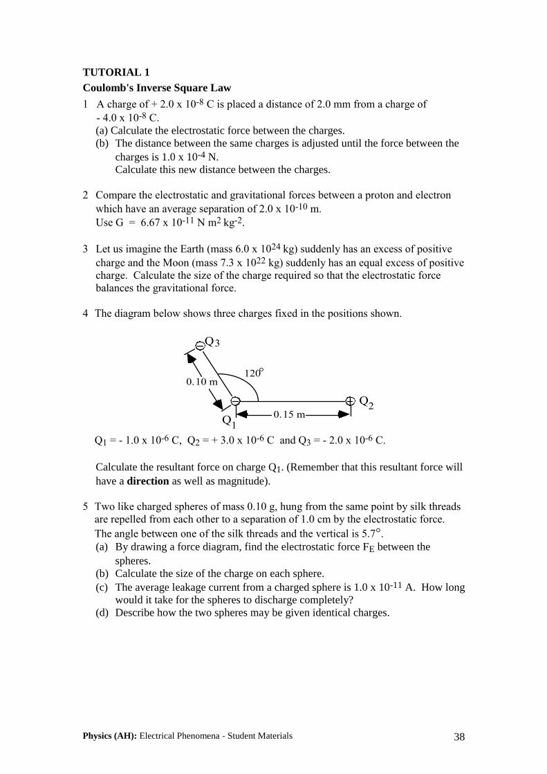
Physics (AH): Electrical Phenomena - Student Materials 38
TUTORIAL 1
Coulomb's Inverse Square Law
1 A charge of + 2.0 x 10⁻⁸ C is placed a distance of 2.0 mm from a charge of
- 4.0 x 10⁻⁸ C.
(a) Calculate the electrostatic force between the charges.
(b) The distance between the same charges is adjusted until the force between the
charges is 1.0 x 10⁻⁴ N.
Calculate this new distance between the charges.
2 Compare the electrostatic and gravitational forces between a proton and electron
which have an average separation of 2.0 x 10⁻¹⁰ m.
Use G = 6.67 x 10⁻¹¹ N m2 kg-2.
3 Let us imagine the Earth (mass 6.0 x 1024 kg) suddenly has an excess of positive
charge and the Moon (mass 7.3 x 10²² kg) suddenly has an equal excess of positive
charge. Calculate the size of the charge required so that the electrostatic force
balances the gravitational force.
4 The diagram below shows three charges fixed in the positions shown.
0.15 m
0.10 m120°
Q2
Q1
Q3
Q1 = - 1.0 x 10⁻⁶ C, Q2 = + 3.0 x 10⁻⁶ C and Q3 = - 2.0 x 10⁻⁶ C.
Calculate the resultant force on charge Q1. (Remember that this resultant force will
have a direction as well as magnitude).
5 Two like charged spheres of mass 0.10 g, hung from the same point by silk threads
are repelled from each other to a separation of 1.0 cm by the electrostatic force.
The angle between one of the silk threads and the vertical is 5.7°.
(a) By drawing a force diagram, find the electrostatic force FE between the
spheres.
(b) Calculate the size of the charge on each sphere.
(c) The average leakage current from a charged sphere is 1.0 x 10⁻¹¹ A. How long
would it take for the spheres to discharge completely?
(d) Describe how the two spheres may be given identical charges.

Physics (AH): Electrical Phenomena - Student Materials 39
6 In an experiment to show Coulomb's Law, an insulated, light, charged sphere is
brought close to another similarly charged sphere which is suspended at the end of
a thread of length 0.80 m. The mass of the suspended sphere is 0.50 g.
It is found that the suspended sphere is displaced to the left by a distance of 16 mm
as shown below.
0.80 m
16 mm
(not to scale)
(a) Make a sketch showing all of the forces acting on the suspended sphere.
(b) Calculate the electrostatic force acting on the suspended sphere.
7. Explain how a charged strip of plastic can pick up small pieces of paper even
although the paper has no net charge.

Physics (AH): Electrical Phenomena - Student Materials 40
TUTORIAL 2
Electric Field Strength
1 What is the electric field strength at a point where a small object carrying a charge
of 4.0 C experiences a force of 0.02 N?
2 (a) Calculate the size of a point charge required to give an electric field strength of
1.0 N C-1 at a distance of 1.0 m from the point charge.
(b) State the magnitude of the electric field strength at a distance of 2.0 m from the
point charge.
3 (a) Calculate the electric field strength due to an -particle at a point 5.0 mm
from the -particle.
(b) How would the electric field strength calculated in (a) compare with the
electric field strength at a point 5.0 mm from a proton?
4 The diagram below shows two charges of +10.0 nC and +18.8 nC respectively
separated by 0.13m.
P
0.12 m
0.13 m
0.05 m
++10 nC 18.8 nC
(a) Calculate the magnitude of the resultant electric field strength at the point P as
shown in the diagram above.
(b) Make a sketch like the one above and show the direction of the resultant
electric field strength at the point P.
Angles are required on your sketch.
5 A negatively charged sphere, of mass 2.0 x 10⁻⁵ kg, is held stationary in the space
between two charged metal plates as shown in the diagram below.
+ + ++ +
(a) The sphere carries a charge of - 5.0 x 10 -9 C. Calculate the size of the
electric field strength in the region between the metal plates.
(b) Make a sketch of the two plates and the stationary charged sphere. Show the
shape and direction of the resultant electric field in the region between the
plates.

Physics (AH): Electrical Phenomena - Student Materials 41
6 Two charges of +8.0 x 10⁻⁹ C and +4.0 x 10⁻⁹ C are held a distance of 0.20 m
apart.
(a) Calculate the magnitude and direction of the electric field strength at the mid-
point between the charges.
(b) Calculate the distance from the 8.0 x 10⁻⁹ C charge at which the electric field
strength is zero.
(c) The 4.0 x 10⁻⁹ C charge has a mass of 5.0 x 10⁻⁴ kg.
(i) Calculate the magnitude of the electrostatic force acting on the charge.
(ii) Calculate the magnitude of the gravitational force acting on the mass.
7 Copy and complete the electric field patterns for:
(a) the electric field between two parallel plates which have equal but opposite
charges
+ ++ ++
(b) the electric field around 2 unequal but opposite charges.
+2Q -Q
+ _
8 Draw electric field lines and equipotential surfaces for the two oppositely charged
parallel plates shown in the sketch below. (Include the fringing effect usually
observed near the edge of the plates).
+ + ++ +

Physics (AH): Electrical Phenomena - Student Materials 42
TUTORIAL 3
Electrostatic Potential
1 Calculate the electrostatic potential at a point, P, which is at a distance of 0.05 m
from a point charge of + 3.0 x 10⁻⁹ C.
2 Small spherical charges of +2.0 nC, -2.0 nC, +3.0 nC and +6.0 nC are placed in
order at the corners of a square of diagonal 0.20 m as shown in the diagram below.
+
+ +
C
_+ 2.0 nC - 2.0 nC
+ 3.0 nC+ 6.0 nC
D
(a) Calculate the electrostatic potential at the centre, C, of the square.
(b) D is at the midpoint of the side as shown.
Calculate the electrostatic potential difference between point C and point D.
3 A hydrogen atom may be considered as a charge of + 1.6 x 10⁻¹⁹ C separated from
a charge of -1.6 x 10⁻¹⁹ C by a distance of 5.0 x 10⁻¹¹ m.
Calculate the potential energy associated with an electron in a hydrogen atom.
4 Consider an equilateral triangle PQR where QR = 20 mm. A charge of
+1.0 x 10⁻⁸ C is placed at Q and a charge of -1.0 x 10⁻⁸ C is placed at R. Both
charges are fixed in place.
(a) Calculate the electric field strength at point P.
(b) Calculate the electrostatic potential at point P.
5 The diagram below shows two horizontal metal plates X and Y which are separated
by a distance of 50 mm.. There is a potential difference between the plates of
1200 V. Note that the lower plate, X, is earthed.
+
-
Y
X
+ + + + +
(a) Draw a sketch graph to show how the potential varies along a line joining the
mid-point of plate X to the mid-point of plate Y.
(b) Calculate the electric field strength between the plates.
(c) Explain how the value for the electric field strength can be obtained from the
graph obtained in (a).

Physics (AH): Electrical Phenomena - Student Materials 43
6 (a) State what is meant by an equipotential surface.
(b) The sketch below shows the outline of the positively charged dome of a Van
de Graaff generator. +
++
+
+
+
+ Copy this sketch and show the electric field lines and equipotential surfaces
around the charged dome.
7 Two oppositely charged parallel plates have a potential difference of 1500 V
between them. If the plates are separated by a distance of 20 mm calculate the
electric field strength, in V m-1, between the plates.
8 A uniform electric field is set up between two oppositely charges parallel metal
plates by connecting them to a 2000 V d.c. supply. The plates are 0.15 m apart.
(a) Calculate the electric field strength between the plates.
(b) An electron is released from the negative plate.
(i) State the energy change which takes place as the electron moves from the
negative to the positive plate.
(ii) Calculate the work done on the electron by the electric field.
(iii) Using your answer to (ii) above calculate the velocity of the electron as it
reaches the positive plate.
9 A proton is now used in the same electric field as question 8 above. The proton is
released from the positive plate.
(a) Describe the motion of the proton as it moves towards the negative plate.
(b) (i) Describe how the work done on the proton by the electric field compares
with the work done on the electron in question 8.
(ii) How does the velocity of the proton just as it reaches the negative plate
compare with the velocity of the electron as it reaches the positive plate in
the previous question?
10 (a) A sphere of radius 0.05 m has a potential at its surface of 1000 V. Make a
sketch of the first 5 equipotential lines outside the sphere if there is 100 V
between the lines. (i.e. calculate the various radii for these potentials).
(b) Calculate the charge on the sphere.
11 (a) Using the equation v = m
2eV , calculate the speed of an electron which has
been accelerated through a potential difference of 1.0 x 10⁶ V.
(b) Is there anything wrong with your answer?
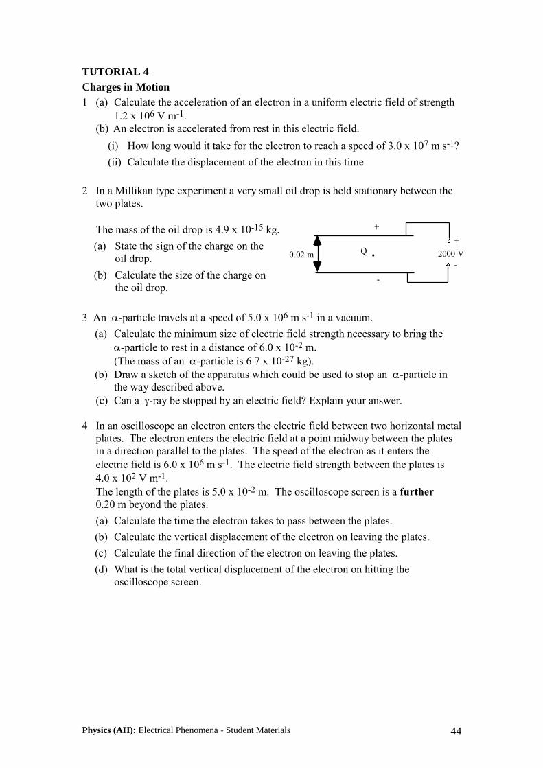
Physics (AH): Electrical Phenomena - Student Materials 44
TUTORIAL 4
Charges in Motion
1 (a) Calculate the acceleration of an electron in a uniform electric field of strength
1.2 x 10⁶ V m-1.
(b) An electron is accelerated from rest in this electric field.
(i) How long would it take for the electron to reach a speed of 3.0 x 10⁷ m s-1?
(ii) Calculate the displacement of the electron in this time
2 In a Millikan type experiment a very small oil drop is held stationary between the
two plates.
The mass of the oil drop is 4.9 x 10⁻¹⁵ kg.
(a) State the sign of the charge on the
oil drop.
(b) Calculate the size of the charge on
the oil drop.
•Q0.02 m
+
-
+
-
2000 V
3 An -particle travels at a speed of 5.0 x 10⁶ m s-1 in a vacuum.
(a) Calculate the minimum size of electric field strength necessary to bring the
-particle to rest in a distance of 6.0 x 10⁻² m.
(The mass of an -particle is 6.7 x 10⁻²⁷ kg).
(b) Draw a sketch of the apparatus which could be used to stop an -particle in
the way described above.
(c) Can a -ray be stopped by an electric field? Explain your answer.
4 In an oscilloscope an electron enters the electric field between two horizontal metal
plates. The electron enters the electric field at a point midway between the plates
in a direction parallel to the plates. The speed of the electron as it enters the
electric field is 6.0 x 10⁶ m s-1. The electric field strength between the plates is
4.0 x 10² V m-1.
The length of the plates is 5.0 x 10⁻² m. The oscilloscope screen is a further
0.20 m beyond the plates.
(a) Calculate the time the electron takes to pass between the plates.
(b) Calculate the vertical displacement of the electron on leaving the plates.
(c) Calculate the final direction of the electron on leaving the plates.
(d) What is the total vertical displacement of the electron on hitting the
oscilloscope screen.

Physics (AH): Electrical Phenomena - Student Materials 45
5 Electrons are accelerated through a large potential difference of 7.5 x 10⁵ V. The
electrons are initially at rest.
Calculate the speed reached by these electrons.
6 In the Rutherford scattering experiment -particles are fired at very thin gold foil
in a vacuum. On very rare occasions an -particle is observed to rebound back
along its incident path.
(a) Explain why this is not observed very often.
(b) The -particles have a typical speed of 2.0 x 10⁷ m s-1.
Calculate the closest distance of approach which an -particle could make
towards a gold nucleus in a head-on collision. The atomic number of gold is
79. The mass of the -particle is 6.7 x 10⁻²⁷ kg.
7 In Millikan's experiment, an negatively charged oil drop of radius 1.62 x 10⁻⁶ m is
held stationary when placed in an electric field of strength 1.9 x 10⁵ V m-1.
(The density of the oil is 870 kg m-3, and the volume of a sphere is 4
3 r3.)
(a) Calculate the mass of the oil drop.
(b) Calculate the charge on the oil drop.
(c) How many electronic charges is your answer to (b) equivalent to?
8 A charged particle has a charge-to-mass ratio of 1.8 x 10¹¹ C kg-1.
Calculate the speed of one such particle when it has been accelerated through a
potential difference of 250 V.

Physics (AH): Electrical Phenomena - Student Materials 46
TUTORIAL 5
Force on a Conductor
1 A straight wire, 0.05 m long, is placed in a uniform magnetic field of magnetic
induction 0.04 T.
The wire carries a current of 7.5 A, and makes an angle of 60° with the direction of
the magnetic field.
(a) Calculate the magnitude of the force exerted on the wire.
(b) Draw a sketch of the wire in the magnetic field and show the direction of the
force,
(c) Describe the conditions for this force to be a maximum.
2 A straight conductor of length 50 mm carries a current of 1.4 A. The conductor
experiences a force of 4.5 x 10⁻³ N when placed in a uniform magnetic field of
magnetic induction 90 mT.
Calculate the angle between the conductor and the direction of the magnetic field.
3
0.75 m
X X X X X
X X X X X
X X X X X
X X X X X
A wire of length 0.75 m and mass
0.025 kg is suspended from two very
flexible leads as shown opposite. The
wire is in a magnetic field of magnetic
induction 0.50 T.
As the sketch shows, the magnetic field
direction is ‘into the page’.
(a) Calculate the size of the current in the wire necessary to remove the tension in
the supporting leads.
(b) Copy the sketch and show the direction of the electron current which produced
this result.
4 The sketch below shows the rectangular coil of an electric motor. The coil has 120
turns and is 0.25 m long and 0.15 m wide and carries a current of 0.25 A. It lies
parallel to a magnetic field of magnetic induction 0.40 T. The sketch shows the
directions of the forces acting on the coil.
(a) Calculate the magnitude of the force, F, on each of the wires shown.
(b) Calculate the torque which acts on the coil when in this position.
(c) State and explain what will happen to this torque as the coil starts to rotate in
the magnetic field.

Physics (AH): Electrical Phenomena - Student Materials 47
5 The diagram below shows a force-on-a-conductor balance set up to measure the
magnetic induction between two flat magnets in which a north pole is facing a
south pole.
The length of the wire in the magnetic field is 0.06 m.
When the current in the wire is zero, the reading on the balance is 95.6 g. When
the current is 4.0 A the reading on the balance is 93.2 g.
(a) Calculate the magnitude and direction of the force on the wire from these
balance readings.
(b) Calculate the size of the magnetic induction between the poles of the magnets.
(c) Suggest what the reading on the balance would be if the connections to the
wire from the supply were reversed. Explain your answer.
(d) Suggest what the reading on the balance would be if one of the magnets is
turned over so that the north face on one magnet is directly opposite the north
face of the other magnet. Explain your reasoning.
6 Two parallel wires 0.20 m apart carry large direct currents to an iron recycling
plant. The large currents passing into the metal generate enough heat to make the
iron melt. It can then be made into new shapes.
(a) Calculate the force between two such wires 16 m long if they each carry a
current of 2500 A.
(b) Hence explain why these wires are not suspended freely on their route to the
iron smelter.

Physics (AH): Electrical Phenomena - Student Materials 48
TUTORIAL 6
Charged Particles in Magnetic Fields
1 A particle carrying a positive charge of 1.6 x 10⁻¹⁹ C travels at 1.0 x 10⁷ m s-1 and
enters a magnetic field at an angle of 45°. The force experienced by the particle is
3.0 x 10⁻¹⁷ N.
Calculate the size of the magnetic induction required to produce this result.
2 Close to the equator the horizontal component of the Earth's magnetic field has a
magnetic induction of 3.3 x 10⁻⁵ T. A high energy proton arrives from outer space
with a vertical velocity of 2.8 x 10⁸ m s-1.
Show that the ratio of the magnetic force, Fm, to gravitational force, Fg, experienced
by the proton is given by Fm
Fg = 3.2 x 10¹⁰.
3 Inside a bubble chamber, a proton is injected at right angles to the direction of the
magnetic field of magnetic induction 0.28 T. The kinetic energy of the proton is
4.2 x 10⁻¹² J.
Calculate the radius of the circle described by the track of the proton.
4 An electron and an alpha particle both make circular orbits in the same magnetic
field. Both particles have the same orbital speed. The mass of an alpha particle is
6.68 x 10⁻²⁷ kg.
Calculate the ratio particles alpha ofrotation offrequency
electrons ofrotation offrequency .
5 A cyclotron has an oscillator frequency of 1.2 x 10⁷ Hz and a maximum effective
dee radius of 0.50 m. The sketch below shows the geometry of the cyclotron. The
deflector plate is mounted at the maximum radius of 0.50 m and its purpose is to
ensure that the charged particles exit successfully.
(a) Show that the frequency of rotation is given by f = qB
2m .
(b) The cyclotron is used to accelerate deuterons from rest. Calculate the
magnetic induction, of the magnetic field of the cyclotron, needed to
accelerate the deuterons. (A deuteron is an isotope of hydrogen, containing a
proton and a neutron, with a mass of 3.34 x 10⁻²⁷ kg.)
(c) Calculate the kinetic energy of the emerging deuterons.

Physics (AH): Electrical Phenomena - Student Materials 49
6 (a) Certain charged particles can be 'selected' from a beam of charged particles if
they are made to enter crossed electric and magnetic fields. The directions of
the fields are mutually perpendicular.
Show that those particles with a velocity equal to the ratio E
B will be
undeflected.
(b) A velocity selector such as that in (a) above has a magnetic induction of
0.70 T and an electric field strength of 1.4 x 10⁵ V m-1.
Calculate the velocity of the undeflected charged particles which pass through
the crossed fields.
(c) The sketch below shows a mass spectrometer arrangement used to deflect ions.
After the exit slit from the velocity selector there is only a magnetic field
present. (The final position of the ions is detected by a photographic plate).
(i) Negatively charged neon ions, which carry one extra electron, emerge
from the velocity selector into a uniform magnetic field of magnetic
induction 0.70 T. The ions follow the semicircular path shown above.
The radius of the circle is 70 mm.
Calculate the mass of the neon ions.
(ii) Explain how the mass spectrometer can show the presence of different
isotopes of neon.
(Isotopes are nuclei having the same atomic number but different mass
numbers).
7 An alpha particle travels in a circular orbit of radius 0.45 m while moving through
a magnetic field of magnetic induction 1.2 T. Calculate:
(a) the speed of the alpha particle in its orbit
(b) the orbital period of the alpha particle
(c) the kinetic energy of the alpha particle in its orbit.

Physics (AH): Electrical Phenomena - Student Materials 50
8 The diagram below shows the Earth's magnetic field. Three positively charged
particles, X, Y and Z approach the Earth along the directions shown.
Path Y is perpendicular to the direction of the Earth’s magnetic field lines.
(a) For each of the particles, describe the path followed in the Earth's magnetic
field.
(b) A proton approaches the earth along path Y with a speed of 2.0 x 10⁶ m s
-1.
Calculate the radius of the path of the proton at a point where the magnetic
induction of the Earth is 1.3 x 10⁻⁵
T.
9. In an experiment to measure the charge to mass ratio for an electron, apparatus
similar to that shown on page 26 is used.
(a) Crossed electric and magnetic fields are applied to produce an undeflected
beam. The current, I, in the Helmholtz coils is measured to be 0.31 A.
The p.d., V, across the plates is 1200 V.
(i) Show that the velocity, v, of the electrons between the plates is given by
v = VBd
where d is the plate separation and B the magnetic induction.
(ii) The magnetic induction, B, is given by 9x10 NI
a
-7
where N, the number of
turns, is 320 and a, the effective radius of the coils, is 0.073 m.
Calculate the magnetic induction B.
(iii) The plate separation, d, is 0.045 m.
Calculate the magnitude of the velocity of the electrons.
(b) The electric field is switched off and the above magnetic field only is applied.
A deflection, y, of 0.015 m is measured.
(i) Show that the charge to mass ratio e
m =
vrB
where r is the radius of the
curved path of the electrons when only the magnetic field is applied.
(ii) The radius, r, is given by r = (L2 + y
2)/2y where L, the length of the plates,
is 0.055 m.
Calculate the charge to mass ratio for the electrons from this data.

Physics (AH): Electrical Phenomena - Student Materials 51
10 The sketch below shows the layout of the apparatus which allows crossed
electric and magnetic fields to be applied to an electric beam. (The Helmholtz
coils which produce the magnetic field 'into the paper' have been omitted for
clarity).
The screen is 0.05 m square. The length, L, and separation, d, are both 0.05 m.
(a) With only the electric field switched on the p.d. between the plates is set at
1200 V. The vertical deflection, y, of the electron beam at the end of the
plates is 1.0 cm.
Calculate the electric field strength between the plates which provides this
deflection.
(b) (i) Both the electric and magnetic fields are now applied. The electron beam
is undeflected when the current to the Helmholtz coils is 0.25 A. The
coils have 320 turns and an effective radius of 0.068 m.
Using the expression B = 8oNI
125 r , calculate the value this gives for the
magnetic induction between the plates.
(ii) Calculate the speed of the electrons as they enter the plates.
(c) With the electric field only applied, the electron beam has a vertical deflection,
y of 1.0 cm at the end of the plates.
(i) Show that the deflection y = 12
a L
v
2
2
where a is the acceleration produced by the electric field and v is the
speed of the electrons entering the plates as shown in the diagram.
(ii) Using the data in the question, calculate a value for the charge to mass
ratio, e
m , for the electron.

Physics (AH): Electrical Phenomena - Student Materials 52
11. Apparatus similar to that shown in question 10 is used in another experiment to
determine the charge to mass ratio for the electron. The length of the plates L and
their separation d are 0.05 m.
In this experiment the p.d. across the electron gun is set at 1000 V. Assuming the
electrons leave the cathode with zero speed, the speed of the electrons entering
the plates can be determined using this electron gun potential difference.
(a) Show that e
m =
v2x1000
2
where v is the speed of the electrons as they leave
the electron gun.
(b) Both the electric and magnetic fields are applied to give an undeflected beam.
The p.d. across the plates is 1000 V. The current in the Helmholtz coils to
give an undeflected beam is measured to be 0.26 A.
(i) Use the expression B = 9 x 10 NI
r
-7
where the number of turns, N, is 320
and the effective radius r of the coils is 0.068 m, to calculate the size of
the magnetic induction between the plates.
(ii) Calculate the magnitude of the speed v of the undeflected electrons when
they are between the plates.
(c) Calculate the charge to mass ratio for the electrons from this data.
(d) The overall uncertainty in this experiment was estimated to be 5 %.
(i) Express the measured value of the charge to mass ratio as
(value absolute uncertainty).
(ii) Consider the accepted value and comment on the accuracy of this
experiment.

Physics (AH): Electrical Phenomena - Student Materials 53
TUTORIAL 7
Self Inductance
1 The sketch below shows an inductor connected to a 12 V direct supply of
negligible internal resistance. The resistance of the coil is 1 (as shown). When
switched on the current grows from zero. The rate of growth is 400 A s-1 when the
current is 8.0 A.
(a) Calculate the induced e.m.f. across the coil when the current is 8 A.
(b) Calculate the inductance of the coil.
(c) Calculate the rate of increase of current when the switch is closed.
(d) A final steady value of current is produced in the coil.
Find the value of this current.
(e) Calculate the final energy stored in the inductor.
2 An inductor with a removable soft iron core is connected in series with a 3.0 V
direct supply of negligible internal resistance as shown below. A milliammeter is
used to monitor the current in the circuit.
The switch is closed. The graph above shows the variation of current with time.
(a) (i) Explain why it takes some time for the current to reach its maximum
value.
(ii) Why does the current remain constant after it reaches its maximum value.
(b) The soft iron core is then partly removed from the coil and the experiment
repeated.
Draw a sketch graph showing how the current varies against time for this
second experiment. Use the same numerical values on the axes as those in the
graph above.
(c) Calculate the resistance of the coil.
_
+
L
1
12 V
10 0
15
I/mA
t/s
+
_ L
A

Physics (AH): Electrical Phenomena - Student Materials 54
3 In the circuit shown below, the resistance of resistor R is 40 and the inductance
of inductor L is 2.0 H. The resistance of the inductor may be neglected. The
supply has an e.m.f. of 10 V and a negligible internal resistance.
(a) Immediately after the switch is closed:
(i) state the p.d. across the 40 resistor
(ii) calculate the size of the current
(iii) state the induced e.m.f. across the 2.0 H inductor
(iv) calculate the energy stored in the inductor.
(b) Some time later the current reaches a value of 0.040 A.
(i) At this time, calculate the p.d. across R.
(ii) Calculate the p.d. across the inductor at this time.
(iii) Hence calculate the rate of growth of current when the current in the
circuit is 0.040 A.
(iv) Calculate the energy stored in the inductor.
4 (a) Describe what is meant by the self-inductance of a coil.
(b) The circuit diagram below shows a resistor, inductor and two lamps connected
to a direct supply of 10 V. The supply has negligible internal resistance. The
rating of each lamp is 6 V, 3 W.
After the switch is closed each lamp operates at its rated power. However
lamp Y lights up before lamp X.
(i) Explain why lamp Y lights before lamp X.
(ii) The current in lamp X grows at a rate of 0.50 A s-1 just as the switch is
closed. Calculate the inductance of the coil.
(iii) Calculate the resistance of the coil.
R
_ +
L
10 V
R
S
_
+ Y
L
X
10 V

Physics (AH): Electrical Phenomena - Student Materials 55
5. The diagram below shows the principle of the spark plug for a car engine.
The cam, which is rotated by the engine, makes and breaks contact at S. This
switches on and off the current to the primary of a transformer.
When the contact at S is opened a high voltage spark of around 20 kV is induced
across the spark plug.
(a) Explain why a voltage is induced across the spark plug particularly when S is
opened.
(b) Explain whether a step-up or step-down transformer would be more useful in
this case.
(c) Where does the energy for the spark come from?
6 The magnet in the sketch below is mounted like a pendulum. It is allowed to
swing to and fro into and out of a coil which has N turns.
(a) Sketch a graph to show the variation of induced e.m.f. with time as the
pendulum magnet swings to and fro.
(b) What is the induced e.m.f. when the magnet momentarily stops?
(c) State what happens to the induced e.m.f. as the magnet reverses its direction of
movement.
(d) What happens to the induced e.m.f. at the positions where the magnet moves
fastest?
primary
_ + 12 V
car battery
cam
contact S
secondary
spark
plug

Physics (AH): Electrical Phenomena - Student Materials 56
7 A circuit is set up as shown below.
The a.c. supply is of constant amplitude but variable frequency. The frequency of
the supply is varied from a very low frequency to a very high frequency.
Explain what you would expect to happen to the average brightness of each of the
lamps X, Y and Z as the frequency is increased.
8 The output from an amplifier is connected across XY in the circuit shown below.
This is designed to direct low frequency signals to one loudspeaker and high
frequency signals to the other loudspeaker.
(a) Suggest which of the loudspeakers A or B is intended to reproduce high
frequency signals.
(b) Explain how the high and low frequency signals are separated by this circuit.
Z Y
X
Y
X
C1
L A C2
B

Physics (AH): Electrical Phenomena - Student Materials 57
TUTORIAL 8
Forces of Nature
1 (a) (i) Calculate the electrostatic force between two protons in the nucleus of
iron. Assume a separation of 4.0 x 10⁻¹⁵ m between the protons.
(ii) Is this force attractive or repulsive?
(b) (i) Calculate the gravitational attraction between two protons separated by
4.0 x 10⁻¹⁵ m.
(ii) Is this force attractive or repulsive?
(iii) is this force large enough to balance the electrostatic force between the
protons?
(iv) Hence explain why the iron nucleus does not fly apart.
2. (a) Briefly state the difference between the ‘strong’ and ‘weak’ nuclear forces.
(b) Give an example of a particle decay associated with the weak nuclear force.
(c) Comment on the range of the strong and weak nuclear forces.
3 Neutron and protons are considered to be composed of quarks.
(a) How many quarks are in each particle?
(b) Briefly comment on the different composition of the neutron and proton.

Physics (AH): Electrical Phenomena - Student Materials 58
ACTIVITY 1A (Outcome 3)
Title Force on a conductor in a magnetic field and current in the
conductor
Apparatus Stiff wire board, ammeter, power supply, rheostat, connecting leads, top
pan balance, mounted magnadur magnets.
Instructions
Set up the apparatus as shown in the diagram.
Adjust the rheostat to give suitable current in the wire.
Note the ammeter reading and the reading on the balance
. Calculate the force exerted on the wire
Repeat for different current values.
Use an appropriate graphical format to show the relationship between the
force on the conductor and current.

Physics (AH): Electrical Phenomena - Student Materials 59
ACTIVITY 1B (Outcome 3)
Title Force on a conductor in a magnetic field and current in the
conductor
Apparatus Top-pan balance, wires, magnadur magnets, d.c. supply.
Instructions
Set up the apparatus as shown in the diagram.
Sit the yoke, with the attached magnets, on the top-pan balance.
Suspend a wire from a firm insulating support in the space between the
magnets so that the wire is at right angles to the magnetic field.
Note the reading on the balance.
Connect the d.c. supply and pass a current through the wire.
Note the new reading on the balance.
Hence determine the force on the conductor due to the magnetic field.
Repeat for different values of current.
Use an appropriate graphical format to show the relationship between the force
on the conductor and current.

Physics (AH): Electrical Phenomena - Student Materials 60
ACTIVITY 2
Title Force on a conductor in a magnetic field and length of wire in the
field
Apparatus Top-pan balance, wires, magnadur magnets, d.c. supply.
Instructions
Set up the apparatus as shown in the diagram.
Sit the yoke, with the attached magnets, on the top-pan balance.
Suspend a wire from a firm insulating support in the space between the
magnets so that the wire is at right angles to the magnetic field.
Note the reading on the balance.
Connect the d.c. supply and pass a current through the wire.
Note the new reading on the balance.
Hence determine the force on the conductor due to the magnetic field.
Alter the length of the wire inside the magnetic field and repeat the
experiment.
Use an appropriate graphical format to show the relationship between the force
on the conductor and length of wire.

Physics (AH): Electrical Phenomena - Student Materials 61
ACTIVITY 3
Title Force on a conductor in a magnetic field and orientation of the wire.
Apparatus Top-pan balance, wires, magnadur magnets, d.c. supply.
Instructions
Set up the apparatus as shown in the diagram.
Sit the yoke, with the attached magnets, on the top-pan balance.
Suspend a wire from a firm insulating support in the space between the
magnets so that the wire is at right angles to the magnetic field.
Note the reading on the balance.
Connect the d.c. supply and pass a current through the wire.
Note the new reading on the balance.
Hence determine the force on the conductor due to the magnetic field.
Ensure that the same length of wire is in the magnetic field rotate the wire so
that it is at an angle to the magnetic field.
Measure this angle.
Pass the same current used before through the wire and note the new balance
reading.
Repeat for other angles of orientation to the magnetic field.
Use an appropriate format to show the relationship between the force on the
conductor and orientation of the wire.

Physics (AH): Electrical Phenomena - Student Materials 62
ACTIVITY 4
Title Magnetic induction around a long straight wire
Apparatus Long straight wire on a wooden frame, signal generator, voltmeter,
search coil, metre stick
Instructions
Set the signal generator to about 4000 Hz.
The induced e.m.f. recorded on the voltmeter is a measure of the magnetic
induction at that position.
Set the search coil to have the maximum e.m.f. induced across it.
Move the search coil at right angles to the wire from P to Q.
Note the reading on the voltmeter at intervals of 5 cm, from a point 50 cm on
one side of the wire to a point 50 cm on the other side of the wire.
Use an appropriate graphical format to show the relationship between
magnetic induction and distance from the wire.
Q P Search coil
Signal generator
4000 Hz Voltmeter
1.5 m
Return lead

Physics (AH): Electrical Phenomena - Student Materials 63
ACTIVITY 5
Title e/m for an electron
Apparatus Cathode ray tube with Helmholtz coils, variable EHT unit, supply to
coils, multimeters
Instructions
Switch on the cathode ray tube to produce the electron beam.
Switch on the electric field between the deflection plates.
Adjust the current to the deflecting coils to produce an undeflected
beam.
For crossed electric and magnetic fields and an undeflected beam:
eE = evB.
If the electron is emitted with zero velocity then
½ mv2 = eV
where V is the cathode-anode p.d.
Using the above equations, eliminate v and write down an expression for
e/m for the electrons.
Since E = V
d
p where Vp is the p.d. across the deflecting plates, measure
the separation d of the deflecting plates.
The magnetic induction B through the coils is given by 9 x 10⁻⁷
NIr
.
Measure the current I in the coils.
Find the number of turns, N, of the coils and the radius, r, of the coils.
Determine a value for e/m for the electrons.

Physics (AH): Electrical Phenomena - Student Materials 64
ACTIVITY 6A (Outcome 3)
Title Self inductance of a coil
Apparatus Direct current supply, inductor, resistor, switch, data capture device.
Instructions
Set up the circuit as shown in the circuit diagram.
Start the data capture device. This is set to measure the p.d. across the
resistor with time.
Close the switch. (This is to ensure that none of the initial data is lost.)
At the end of the experiment, remove the data capture device from the circuit
before switching off. When switching the current off a high back e.m.f. will
be generated which could cause damage.
The data capture device displays the current using the known value of the
resistance of the resistor.
Use an appropriate graphical format to display the variation of current with
time.
The gradient of a current-time graph is equal to dIdt
.
Draw the gradient to your graph at time t=0.
Determine the inductance of the inductor.
-
+
To data capture to measure VR
VL

Physics (AH): Electrical Phenomena - Student Materials 65
ACTIVITY 6B (Outcome 3)
Title Self inductance of a coil
Apparatus 9 V battery, 45 kH inductor, switch, ammeter, stop watch.
Instructions
Set up the circuit as shown in the circuit diagram.
Close the switch and start the stop watch at the same time.
Note the ammeter reading at regular time intervals.
Use an appropriate graphical format to display the variation of current with
time.
The gradient of a current-time graph is equal to dIdt
.
Draw the gradient to your graph at time t=0.
Determine the inductance of the inductor.
A

Physics (AH): Electrical Phenomena - Student Materials 66
ACTIVITY 7A (Outcome 3)
Title Current and frequency in an inductive circuit
Apparatus Signal generator, a.c. voltmeter or oscilloscope, a.c. ammeter, inductor.
Instructions
Set up the circuit as shown in the circuit diagram.
An oscilloscope may be used in place of the voltmeter.
Ensure that the supply voltage remains constant throughout the experiment.
Vary the source frequency and record readings of current and frequency, using
a range of 100 Hz to 600 Hz.
Use an appropriate graphical format to show the relationship between current
and frequency.
A
V

Physics (AH): Electrical Phenomena - Student Materials 67
ACTIVITY 7B (Outcome 3)
Title Current and frequency in an inductive circuit
Apparatus Signal generator, a.c. voltmeter or oscilloscope, a.c. ammeter, inductor.
Instructions
Set up the circuit as shown in the circuit diagram.
Switch on the signal generator and set the voltage. This should remain
constant throughout the experiment. The program will warn you if it alters.
Adjust the frequency. The data capture device will display the current using
the known value of the resistance of the resistor, together with the frequency
value.
Use an appropriate graphical format to show the relationship between current
and frequency.
To data capture which samples
voltage and frequency

Physics (AH): Electrical Phenomena - Student Materials 68

Physics (AH): Wave Phenomena - Student Materials 1
WAVE PHENOMENA – STUDENT MATERIAL
Wave Motion
In a wave motion energy is transferred from one position to another with no net
transport of mass.
Consider a water wave where the movement of each water particle is at right angles
(transverse) to the direction of travel of the wave. During the wave motion each
particle, labelled by its position on the x-axis, is displaced some distance y in the
transverse direction. In this case, "no net transfer of mass" means that the water
molecules themselves do not travel with the wave - the wave energy passes over the
surface of the water, and in the absence of a wind/tide any object on the surface will
simply bob up and down.
The Travelling Wave Equation
The value of the displacement y depends on which particle of the wave is being
considered. It is dependent on the x value, and also on the time t at which it is
considered. Therefore y is a function of x and t giving y = f(x,t). If this function is
known for a particular wave motion we can use it to predict the position of any
particle at any time.
Below are 'snapshots' of a transverse wave taken at different times showing how the
displacement of different particles varies with position x.
The following diagram shows the movement of one particle on the wave as a function
of time.
Initial condition at the origin:
y = 0 when t = 0.
For a wave travelling from left to right with speed v, the particle will be performing
SHM in the y-direction.
The equation of motion of the particle will be:
y = a sin t where a is the amplitude of the motion.
The displacement of the particle is simple harmonic. The sine or cosine variation is
the simplest description of a wave.
When y = 0 at t = 0 the relationship for the wave is y = a sin t, as shown above.
When y = a at t = 0 the relationship for the wave is y = a cos t.
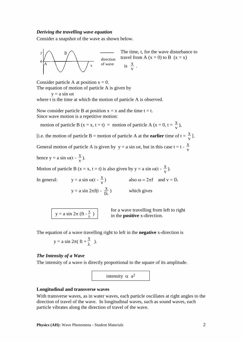
Physics (AH): Wave Phenomena - Student Materials 2
Deriving the travelling wave equation
Consider a snapshot of the wave as shown below.
The time, t, for the wave disturbance to
travel from A (x = 0) to B (x = x)
is xv
.
Consider particle A at position x = 0.
The equation of motion of particle A is given by
y = a sin t
where t is the time at which the motion of particle A is observed.
Now consider particle B at position x = x and the time t = t.
Since wave motion is a repetitive motion:
motion of particle B (x = x, t = t) = motion of particle A (x = 0, t = xv
),
[i.e. the motion of particle B = motion of particle A at the earlier time of t = xv
].
General motion of particle A is given by y = a sin t, but in this case t = t - xv
hence y = a sin t - xv
).
Motion of particle B (x = x, t = t) is also given by y = a sin t - xv
).
In general: y = a sin t - xv
) also f and v = f
y = a sin 2f(t - xf
) which gives
y = a sin 2 (ft - x
)
for a wave travelling from left to right
in the positive x-direction.
The equation of a wave travelling right to left in the negative x-direction is
y = a sin 2( ft + x
).
The Intensity of a Wave
The intensity of a wave is directly proportional to the square of its amplitude.
intensity a2
Longitudinal and transverse waves
With transverse waves, as in water waves, each particle oscillates at right angles to the
direction of travel of the wave. In longitudinal waves, such as sound waves, each
particle vibrates along the direction of travel of the wave.
direction
of wave

Physics (AH): Wave Phenomena - Student Materials 3
Principle of Superposition of Waveforms
Travelling waves can pass through each other without being altered. If two stones are
dropped in a calm pool, two sets of circular waves are produced. These waves pass
through each other. However at any point at a particular time, the disturbance at that
point is the algebraic sum of the individual disturbances. In the above example, when
a ‘trough’ from one wave meets a ‘crest’ from the other wave the water will remain
calm.
A periodic wave is a wave which repeats itself at regular intervals. All periodic
waveforms can be described by a mathematical series of sine or cosine waves, known
as a Fourier Series. For example a saw tooth wave can be expressed as a series of
individual sine waves.
y(t) = - 1
sin t -
1
2 sin 2t -
1
3 sin 3t - .............
The graph below shows the first four terms of this expression.
When all these terms are superimposed (added together) the graph below is obtained.
Notice that this is tending to the sawtooth waveform. If more terms are included it
will have a better saw tooth form.

Physics (AH): Wave Phenomena - Student Materials 4
Phase Difference
A phase difference exists between two points on the same wave.
Consider the snapshots below of a wave travelling to the right in the positive
x-direction.
Points O and D have a phase difference of 2 radians.
They are both at zero displacement and will next be moving in the negative direction.
They are separated by one wavelength ().
Points O and B have a phase difference of radians. They both have zero
displacement but B will next be going positive and O will be going negative. They are
separated by /2. Notice that points A and B have a phase difference of /2.
The table below summarises phase difference and separation of the points.
Phase difference Separation of points
0 0
/4
/2
Notice that phase difference
separation of points =
2
= constant.
If the phase difference between two particles is when the separation of the particles
is x, then
x =
2
.
In general, for two points on a wave separated by a distance x the phase difference is
given by:
= 2 x
where is the phase angle
in radians
Example
A travelling wave has a wavelength of 60 mm. A point P is 75 mm from the origin
and a point Q is 130 mm from the origin.
(a) What is the phase difference between P and Q?
(b) Which of the following statements best describes this phase difference:
‘almost completely out of phase’; ‘roughly ¼ cycle out of phase’;
‘almost in phase’.
Solution
(a) separation of points = 130 - 75 = 55 mm = 0.055 m
phase difference = 20 0550 060..
= 5.76 radians
(b) P and Q are separated by 55 mm which is almost one wavelength, hence they are
‘almost in phase’. Notice that 5.76 radians is 3300, which is close to 360
0.
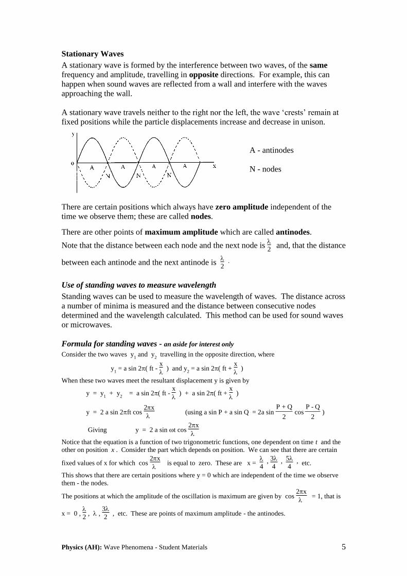
Physics (AH): Wave Phenomena - Student Materials 5
Stationary Waves
A stationary wave is formed by the interference between two waves, of the same
frequency and amplitude, travelling in opposite directions. For example, this can
happen when sound waves are reflected from a wall and interfere with the waves
approaching the wall.
A stationary wave travels neither to the right nor the left, the wave ‘crests’ remain at
fixed positions while the particle displacements increase and decrease in unison.
A - antinodes
N - nodes
There are certain positions which always have zero amplitude independent of the
time we observe them; these are called nodes.
There are other points of maximum amplitude which are called antinodes.
Note that the distance between each node and the next node is
2 and, that the distance
between each antinode and the next antinode is
2 .
Use of standing waves to measure wavelength
Standing waves can be used to measure the wavelength of waves. The distance across
a number of minima is measured and the distance between consecutive nodes
determined and the wavelength calculated. This method can be used for sound waves
or microwaves.
Formula for standing waves - an aside for interest only
Consider the two waves y1 and y
2 travelling in the opposite direction, where
y1 = a sin 2( ft -
x
) and y
2 = a sin 2( ft +
x
)
When these two waves meet the resultant displacement y is given by
y = y1 + y
2 = a sin 2( ft -
x
) + a sin 2( ft +
x
)
y = 2 a sin 2ft cos 2x
(using a sin P + a sin Q = 2a sin
P + Q
2cos
P - Q
2)
Giving y = 2 a sin t cos 2x
Notice that the equation is a function of two trigonometric functions, one dependent on time t and the
other on position x . Consider the part which depends on position. We can see that there are certain
fixed values of x for which cos 2x
is equal to zero. These are x =
4 ,
3
4 ,
5
4 , etc.
This shows that there are certain positions where y = 0 which are independent of the time we observe
them - the nodes.
The positions at which the amplitude of the oscillation is maximum are given by cos 2x
= 1, that is
x = 0 ,
2 , ,
3
2 , etc. These are points of maximum amplitude - the antinodes.
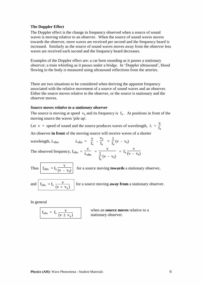
Physics (AH): Wave Phenomena - Student Materials 6
The Doppler Effect
The Doppler effect is the change in frequency observed when a source of sound
waves is moving relative to an observer. When the source of sound waves moves
towards the observer, more waves are received per second and the frequency heard is
increased. Similarly as the source of sound waves moves away from the observer less
waves are received each second and the frequency heard decreases.
Examples of the Doppler effect are: a car horn sounding as it passes a stationary
observer; a train whistling as it passes under a bridge. In ‘Doppler ultrasound’, blood
flowing in the body is measured using ultrasound reflections from the arteries.
There are two situations to be considered when deriving the apparent frequency
associated with the relative movement of a source of sound waves and an observer.
Either the source moves relative to the observer, or the source is stationary and the
observer moves.
Source moves relative to a stationary observer
The source is moving at speed vs and its frequency is fs . At positions in front of the
moving source the waves 'pile up'.
Let v = speed of sound and the source produces waves of wavelength, = v
fs
An observer in front of the moving source will receive waves of a shorter
wavelength, obs. obs = v
fs -
vs
fs =
1
fs (v - vs)
The observed frequency, fobs = v
obs =
v
1
fs (v - vs)
= fs v
(v - vs)
Thus fobs = fs v
(v - vs) for a source moving towards a stationary observer,
and fobs = fs )v(v
v
s for a source moving away from a stationary observer.
In general
fobs = fs )v(v
v
s
when an source moves relative to a
stationary observer.

Physics (AH): Wave Phenomena - Student Materials 7
Observer moves relative to stationary source.
Consider in this case the number of waves received in a given time, t.
The number of waves produced by the source in time t = fs x t = v x t
If the observer is moving towards the source at speed vo , an extra vo
x t
waves will be heard in that time.
Thus total number of waves received in time t = v t +
ov
t
Number of waves per second, fobs =
v
t +
vo
t
t =
v + vs
= fs
v + vo
v
Thus fobs = fs v + vo
v for an observer moving towards a stationary source,
and fobs = fs v - vo
v for an observer moving away from a stationary source.
In general
fobs = fs v
)v(v o
when an observer moves relative to a
stationary source.
Doppler red shift
It is interesting to note that this effect also occurs with light waves and can be used to
calculate the speed that a star is moving away from Earth from the shift in colour
observed towards the red i.e Doppler 'red shift'.
However the above formulae must not be applied to light. Sound waves travel with a
speed relative to a medium. The speed of light is the same for all observers. Light
waves coming from a source, which is moving towards an observer, have exactly the
same speed as the light waves seen by an observer who is moving towards a stationary
source of light.

Physics (AH): Wave Phenomena - Student Materials 8
INTERFERENCE - DIVISION OF AMPLITUDE
Producing interference
Interference of waves occurs when waves overlap. There are two ways to produce an
interference pattern for light: division of amplitude and division of wavefront. Both
of these involve splitting the light from a single source into two beams. We will
consider division of amplitude first and division of wavefront in the next section.
Division of amplitude
This involves splitting a single light beam into two beams, a reflected beam and a
transmitted beam, at a surface between two media of different refractive index. In
some cases multiple reflections can occur and more than two beams are produced.
Before we consider specific examples we need to consider some general properties of
interference.
Coherent Sources
Two coherent sources must have a constant phase difference. Hence they will have
the same frequency.
To produce an interference pattern for light waves the two, or more, overlapping
beams always come from the same single source. When we try to produce an
interference pattern from two separate light sources it does not work because light
cannot be produced as a continuous wave. Light is produced when an electron
transition takes place from a higher energy level to a lower energy level in an atom.
The energy of the photon emitted is given by E = hf where E is the difference in
the two energy levels, f is the frequency of the photon emitted and h is Planck’s
constant. Thus a source of light has continual changes of phase, roughly every
nanosecond, as these short pulses of light are produced. Two sources of light
producing the same frequency will not have a constant phase relationship so will not
produce clear interference effects.
This is not the case for sound waves. We can have two separate loudspeakers,
connected to the same signal generator, emitting the same frequency which will
produce an interference pattern.
Path Difference and Optical Path difference
Sources S1 and S2 are two coherent sources in air.
S
s
o
urS
Q
1
2
The path difference is (S2Q - S1Q). For constructive interference to take place at Q,
the waves must be in phase at Q. Hence the path difference must be a whole number
of wavelengths.
(S2Q - S1Q) = m where m = 0, 1, 2, 3, ... (Note: the letter m is used to denote an integer, not n, since we use n for refractive index.)

Physics (AH): Wave Phenomena - Student Materials 9
Similarly, for destructive interference to take place the waves must be out of phase at
Q by /2 (that is a ‘crest’ from S1 must meet a ‘trough’ from S2).
(S2Q - S1Q) = (m + 1
2 )
Optical path difference
In some situations the path followed by one light beam is inside a transparent material
of refractive index, n. Consider two coherent beams S1 and S2 where S1P is in air and
S2P is in perspex of refractive index n = 1.5. We will consider the point P itself to be
in air.
The geometrical path difference
S1P - S2P is zero.
But will there be constructive interference at P?
The wavelength inside the perspex is less than that in air perspex = air
1.5. Hence the
waves from S1 and S2 may not arrive at P in phase. For example, if there were exactly
Z whole waves between S1P, there will be 1.5 x Z waves between S2P which may or
may not be a whole number of wavelengths.
The optical path length must be considered not the geometrical path length.
Optical path length = refractive index x geometrical path length
Thus the relationships for constructive and destructive interference must be
considered for optical path lengths, S2P and S1P.
For constructive interference (S2P - S1P) = m where m is an integer
For destructive interference (S2P - S1P) = (m + 1
2 )where m is an integer
Phase difference and optical path difference
The optical path difference is the difference in the two optical path lengths, namely
(S2P - S1P) in our general example.
The phase difference is related to the optical path difference:
phase difference = 2
x optical path difference
where is the wavelength in vacuum.
Notice that when the optical path difference is a whole number of wavelengths, the
phase difference is a multiple of 2, i.e. the waves are in phase.
perspex
S2
S1
P

Physics (AH): Wave Phenomena - Student Materials 10
Phase Change on Reflection
To understand interference caused by multiple reflections it is necessary to consider
what happens when a light wave moving in air hits a material such as glass.
On a large scale we can see what happens to the wave when a pulse on a rope or
'slinky' reflects off a dense material such as a wall.
incident
pulse
reflected
pulse
The reflected pulse is said to undergo a
phase change of 180° or radians. The
reflected pulse is 180° out of phase with the
incident pulse. If these two pulses were to
meet they would momentarily cancel as they
passed one another.
There is a similar phase change when a light wave is reflected off a sheet of glass.
In general for light there is a phase change of on reflection at an interface where
there is an increase in optical density, e.g. light going from air to glass. There is no
phase change on reflection where there is a decrease in optical density, e.g. light going
from glass to air.
Thin parallel sided film
Interference by division of amplitude can be produced by thin films as shown below.
A
ra
ys
B
incident monochromatic ray of light
reflected ray
transmitted rays
air glass air
D1 D2
Notice that an extended source can be used. The amplitude of the beam is divided by
reflection and transmission at D1, and again by reflection and transmission at D2 at the
back of the glass sheet.
An eye, at A, will focus the reflected beams and an eye at B will focus the transmitted
beams. Thus interference patterns can be observed in both the reflected and
transmitted beams.

Physics (AH): Wave Phenomena - Student Materials 11
Condition for maxima and minima in the fringes formed in a thin film
r
incident ray
r
r r
i i
E
D
B A
C
F
G
2t
t
1 2
Optical paths from B and D to where the interference fringes are observed are the
same.
BD is perpendicular to ray 1. AC is perpendicular to ray 2.
BF is extended to meet the perpendicular line AE at G.
AFG = 180 - 2r, hence AGF = r, since FAG = r.
AF = GF (isosceles triangle)
Starting at A, ray 2 has an optical path in the film of AFB. Ray 1 has a path AD in
air. Optical path difference = n (AFB) - AD.
Optical path difference = n (AFB) - AD
= n (AF + FB) - AD = n(GF + FB) - AD
= n (GB) - AD = n (GC + CB) - AD
AC and DB represent two successive positions of a wave crest reflected from the
lower surface. Thus the optical paths AD and CB must be the same,
giving n(CB) = AD
Hence = n (GC) + n (CB) - AD = n(GC)
From triangle AGC cos AGC = GCAG
giving cos r = GC2t
Optical path difference = n 2t cos r = 2nt cos r
If = m, we might expect rays 1 and 2 to arrive in phase and produce constructive
interference. However ray 1 undergoes a phase change of on reflection, while ray 2
does not. Hence when 2nt cos r = m there is a minimum.
Destructive interference occurs when: 2nt cos r = m m = 0, 1, 2, 3, ...
Constructive interference occurs when: 2nt cos r +
2 = m m = 0, 1, 2, 3, ...
At near normal incidence, that is viewing the interference effects from directly above,
r 0 and cos r 1 giving
2nt = m for destructive interference.

Physics (AH): Wave Phenomena - Student Materials 12
Example
A sheet of mica is 4.80 m thick. Light of wavelength 512 nm is shone onto the mica.
When viewed from above, will there be constructive, destructive, or partial destructive
interference? The refractive index of mica is 1.60 for light of this wavelength.
Solution
For destructive interference 2nt = m
2 x 1.6 x 4.8 x 10-6
= m x 512 x 10-9
This gives m = 30 which is an integer. Hence destructive interference is observed.
Wedge Fringes
Two glass slides are arranged as shown below.
Division of amplitude takes place at the lower surface of the top glass slide.
A t
m
o
air wedge
incident light
Enlarged view showing the geometry
t
x /2
When viewed from above the optical path difference = 2t
There is a phase difference of on reflection at A. Hence the condition for a dark
fringe is 2t = m assuming an air wedge.
For the next dark fringe t increases by
2 (see right hand sketch above).
Thus the spacing of fringes, x, is such that tan
2 x
giving
x = 2 tan
For a wedge of length L and spacing D
tan = DL
.
The fringe spacing is
given byx =
L2 D
where is the wavelength of
light in air.
In practice the distance across a number of fringes is measured and x determined.
Notice that the fringes are formed inside the wedge, and that the two reflected rays are
diverging. The eye, or a microscope, must be focussed between the plates for viewing
the fringes.
L
D

Physics (AH): Wave Phenomena - Student Materials 13
A wedge can be formed by two microscope slides in contact at one end and separated
by a human hair or ultra thin foil at the other end. In this way the diameter of a
human hair can be measured.
Similarly, if a crystal is placed at the edge and heated, the thermal expansion can be
measured by counting the fringes as the pattern changes.
Non-reflecting Coating
Good quality lenses in a camera reflect very little light and appear dark or slightly
purple. A thin coating of a fluoride salt such as magnesium fluoride on the surface of
the lens allows the majority of the light falling on the lens to pass through.
The refractive index, n, of the coating is chosen such that 1 < n < nglass.
fluoride coating of
refractive index n
d
glass lens
Notice that there is a phase
change of at both the first and
second surfaces.
For cancellation of reflected light:
optical path difference =
2 .
Optical path in fluoride = 2nd
thus 2nd =
2 and
d =
n
Complete cancellation is for one particular wavelength only. Partial cancellation
occurs for other wavelengths.
The wavelength chosen for complete cancellation is in the yellow/green (i.e. middle)
of the spectrum. This is why the lens may look purple because the reflected light has
no yellow present. The red and blue light are partially reflected to produce the purple
colour observed.
Colours in thin films
When a soap film is held vertically in a ring and is illuminated with monochromatic
light it initially appears coloured all over. However when the soap drains downwards
a wedge shaped film is produced, with the top thinner than the bottom. Thus
horizontal bright and dark fringes appear. When illuminated by white light, colours
are formed at positions where the thickness of the film is such that constructive
interference takes place for that particular colour. Just before the soap film breaks,
the top appears black because the film is so thin there is virtually no path difference in
the soap. Destructive interference occurs because of the phase change on reflection.
Similar colours are observed when a thin film of oil is formed on water.

Physics (AH): Wave Phenomena - Student Materials 14
INTERFERENCE - DIVISION OF WAVEFRONT
Division of wavefront
When light from a single point source is incident on two small slits, two coherent
beams of light can be produced. Each slit acts as a secondary source due to
diffraction.
If an extended source is used, each part of the wavefront will be incident on the slit at
a different angle. Each part of the source will then produce a fringe pattern, but
slightly displaced. When the intensity of all the patterns is summed the overall
interference pattern may be lost. However a line source parallel to the slits is an
exception.
Compare this with the use of an extended source in ‘division of amplitude’.
Young's Slits Experiment
The diagram below shows light from a single source of monochromatic light incident
on a double slit. The light diffracts at each slit and the overlapping diffraction
patterns produce interference.
Q centre
D
O
A
B
M d
N
P position of 1
st
bright fringe
x
incident
waves
A bright fringe is observed at P. Angle PMO is .
N is a point on BP such that NP = AP. Since P is the first bright fringe BN =
For small values of AN cuts MP at almost 900 giving angle MAQ = and hence
angle.
Again providing is very small, sin = tan = in radians
From triangle BAN: = d
also from triangle PMO: = x
D
Thus x
D
=
d
or x =
Dd
Giving the fringe separation between adjacent fringes x
x = Dd
Note This formula only applies if x<<D, which gives small. This is likely to be
true for light waves but not for microwaves.
Note The position of the fringes is dependent on the wavelength. Thus if white light
is used we can expect overlapping colours either side of a central white
maximum. The red, with the longer wavelength, will be the furthest from this
white maximum (xred > xviolet since red > violet).

Physics (AH): Wave Phenomena - Student Materials 15
POLARISATION
Polarised and unpolarised waves
Light is a wave motion, and is part of the electromagnetic spectrum. In all
electromagnetic waves the electric field and magnetic field vary. The diagram
below shows a 3-dimensional picture of such a wave.
The above diagram shows the variation of the electric field strength, E, in the x-y
plane and the variation of the magnetic induction, B, in the x-z plane. In this example
the electric field strength is only in one plane. The wave is said to be plane polarised,
or linearly polarised. For example, in Britain this is the way that T.V. waves are
transmitted. Aerials are designed and oriented to pick up the vertical electric field
strength vibrations. These vibrations contain the information decoded by the
electronic systems in the television.
Notice that the electromagnetic wave is made up of two mutually perpendicular
transverse waves. The oscillations of E and B.
Light from an ordinary filament lamp is made up of many separate electromagnetic
waves produced by the random electron transitions in the atoms of the source. So
unlike the directional T.V waves, light waves from a lamp consist of many random
vibrations. This is called an unpolarised wave.
When looking at an unpolarised wave coming towards you the direction of the
electric field strength vector would appear to be vibrating in all direction, as shown in
the diagram (i) on the left below. The magnetic induction vector would be
perpendicular to the electric field strength vector, hence this too would be vibrating in
all directions However when discussing polarisation we refer to the electric field
strength vector only.
All the individual electric field strength vectors could be resolved in two mutually
perpendicular direction to give the other representation of a unpolarised wave, as
shown below in the centre diagram (ii).
The right hand diagram (iii) above represents a polarised wave.
(i) unpolarised wave (ii) unpolarised wave (iii) polarised wave

Physics (AH): Wave Phenomena - Student Materials 16
Longitudinal and transverse waves
Note that only transverse waves can be polarised. Longitudinal waves, e.g. sound
waves, cannot be polarised.
Polarisation using Filters
We can produce a linearly polarised wave if we can somehow absorb the vibrations
in all the other directions except one.
In 1852 Herapath discovered that a crystal of iodo-quinine sulphate transmitted one
plane of polarisation, other planes being absorbed. In 1938 Land produced the
material ‘Polaroid’, which has a series of parallel long hydrocarbon chains. Iodine
atoms impregnate the long chains providing conduction electrons. Light is only
transmitted when the electric field strength vector is perpendicular to the chain.
The arrangement below shows a polaroid filter at X producing linearly polarised light.
The polaroid at X is called a polariser. Vibrations of the electric field strength vector
at right angles to the axis of transmission are absorbed.
eye X Y
axis of
transmission
A second polaroid at Y is placed perpendicular to the first one, as shown above. This
is called an analyser. The analyser absorbs the remaining vibrations because its axis
of transmission is at right angles to the polariser at X and no light is seen by the eye.
The light between X and Y is called linearly or plane polarisation.
These effects also can be demonstrated using microwaves and a metal grid.
T
R
metal grid
The microwaves emitted by the horn are plane polarised. In this example the electric
field strength vector is in the vertical plane. The waves are absorbed by the rods and
re-radiated in all directions. Hence there will be a very low reading on the receiver,
R. When the metal grid is rotated through 90o the waves will be transmitted, and the
reading on the receiver will rise. Notice that the microwaves are transmitted when the
plane of oscillation of the electric field strength vector is perpendicular to the
direction of the rods.
Polarisation by Reflection
Plane polarised waves can be produced naturally by light reflecting from any
electrical insulator, like glass. When refraction takes place at a boundary between two
transparent materials the components of the electric field strength vector parallel to
the boundary are largely reflected. Thus reflected light is partially plane polarised.

Physics (AH): Wave Phenomena - Student Materials 17
Plane polarisation at the Brewster angle
ip ip
r
analyser
air
glass
normal
90 °
refractive index n
Consider a beam of unpolarised light incident on a sheet of smooth glass. This beam
is partially reflected and partially refracted. The angle of incidence is varied and the
reflected ray viewed through an analyser, as shown above. It is observed that at a
certain angle of incidence ip the reflected ray is plane polarised. No light emerges
from the analyser at this angle.
The polarising angle ip or Brewster’s angle is the angle of incidence which causes
the reflected light to be linearly polarised.
This effect was first noted by an experimenter called Malus in the early part of the
nineteenth century. Later Brewster discovered that at the polarising angle ip the
refracted and reflected rays are separated by 90°.
Consider the diagram above, which has this 90° angle marked:
n = sin ip
sin r
but r = (90 - ip) thus sin r = sin (90 - ip) = cos ip
Thus n = sin ip
cos ip = tan ip
n = tan ip
Example
Calculate the polarising angle for glycerol, n = 1.47.
What is the angle of refraction inside the glycerol at the Brewster angle?
Solution
Using the equation n = tan ip 1.47 = tan ip giving ip = 56o.
At the Brewster angle, which is the polarising angle,
angle of refraction + ip = 90o thus angle of refraction = 44
o.
Reduction of Glare by Polaroid sunglasses
When sunlight is reflected from a horizontal surface, e.g. a smooth lake of water, into
the eye, eyestrain can occur due to the glare associated with the reflected light. The
intensity of this reflected beam can be reduced by wearing polaroid sunglasses. These
act as an analyser and will cut out a large part of the reflected polarised light.

Physics (AH): Wave Phenomena - Student Materials 18
TUTORIAL 1
Waves
1 A travelling wave is represented by the equation y = 3 sin 2(10t - 0.2x) where y
is in cm. Calculate, for this wave,
(a) the amplitude
(b) the frequency
(c) the wavelength
(d) the speed.
2 Write the equation for a plane sinusoidal wave travelling in the + x direction
which has the following characteristics:
amplitude = 0.30 m, wavelength = 0.50 m and frequency = 20 Hz.
3 A travelling wave is represented by the following equation:
y1 = 0.20 sin (220t - 30 x) - (i)
where y1 and x are measured in m from the origin.
Write the equation for the displacement, y2, of a wave travelling in the opposite
direction which has twice the frequency and double the amplitude of the wave
represented by equation (i) above.
4 The equation of a transverse wave on a stretched string is represented by:
y = 0.04 sin[2( 0.04
t - 2.0x )] (y and x in metres and t in seconds).
(a) What is the amplitude of the wave?
(b) Calculate the wavelength of the wave.
(c) What is the frequency of the wave?
(d) Describe the movement of any particle of the string over one complete
period, T, of the wave.
5 The equation of a transverse wave travelling in a rope is given by:
y = 0.01 sin (2.0 t - 0.01 x) (y and x in metres and t in seconds).
(a) Calculate the velocity of the wave in the x-direction.
(b) Find the maximum transverse speed of a particle in the rope.
6 The following equation represents a wave travelling in the positive x-direction
y = a sin 2 (ft - x
)
Using the relationships f = 1/T, v = f , and k = 2/ show that the following
are also possible equations for this wave.
(a) y = a sin 2(t
T -
x ) (b) y = a sin (t - kx )
(c) y = a sin 2f (t - x
v ) (d) y = a sin
2
(vt - x)
7 A wave of frequency 500 Hz has a velocity of 350 m s-1.
(a) How far apart are two points which are 60° i.e.
3 out of phase?
(b) What is the phase difference between two displacements at the same point, at
a time separation of 0.001 s?

Physics (AH): Wave Phenomena - Student Materials 19
8 A progressive wave and a stationary wave each have the same frequency of 250
Hz and the same velocity of 30 m s-1.
(a) Calculate the phase difference between two vibrating points on the
progressive wave which are 10 cm apart.
(b) State the equation for the travelling wave if its amplitude is 0.03 m.
(c) Calculate the distance between the nodes of the stationary wave.
9 (a) Explain what is meant by a 'travelling wave' and a 'stationary wave'. State
clearly the differences between the two.
(b) Describe a method involving the formation of standing waves which you
could use to measure the wavelength of microwaves. In your answer you
should include:
a sketch of any apparatus you would use
details of measurements taken
details of how you would arrive at a final answer.
10 (a) The sketch below shows an experimental arrangement to measure the
wavelength of sound waves coming from a loudspeaker.
signal
generator
loudspeaker
oscilloscope
microphone
reflector
The oscilloscope trace shows the level of sound picked up by the microphone
which is moved between the loudspeaker and the reflector.
In one particular trial it was noted that the microphone travelled a distance of
0.24 m between adjacent maxima. The signal generator was set at
700 Hz.
Calculate:
(i) the wavelength and
(ii) the velocity of the sound wave emitted from the loudspeaker.
(b) Another loudspeaker is connected in parallel with the first and the two
sound waves allowed to overlap. The two speakers are facing in the same
direction and the reflector is removed.
Describe and explain what a listener would hear as he walks across in
front of the two speakers.

Physics (AH): Wave Phenomena - Student Materials 20
TUTORIAL 2
The Doppler Effect
1 A police car travelling at 20 m s-1 emits sound waves with a frequency of
1000 Hz from its siren.
(a) Calculate the frequency heard by a stationary observer as the police car
moves towards her.
(b) Calculate the frequency heard by the same observer as the police car moves
away from her.
2 A stationary emergency vehicle emits sound waves with a frequency of
1500 Hz. A motorcyclist travelling at 30 m s-1 passes this vehicle.
(a) Calculate the frequency heard by the motorcyclist as he approaches the
stationary vehicle.
(b) Calculate the frequency heard by the motorcyclist after he has passed the
vehicle.
3 A girl tries out an experiment to illustrate the Doppler effect by spinning a battery
operated siren around her head. The siren emits sound waves with a frequency of
1200 Hz.
(a) Describe what would be heard by an observer standing a few metres away.
(b) The radius of the orbit of the spinning siren is 0.80 m. The siren makes 3.0
revolutions per second. Calculate the range of frequencies heard by the
observer mentioned in (a).
(c) Describe and explain what the girl herself will hear.
4 Derive the expression for the apparent frequency detected
(a) when a source of sound waves moves away from a stationary observer
(b) when an observer moves towards a stationary source of sound waves.
5. On the planet Hsdu, a small male nattra is flying towards a ndo at 0.260 m s-1
. The
nattra is emitting sound waves of frequency 1100 Hz. The stationary ndo hears a
frequency of 1600 Hz. What is the speed of sound on Hsdu?
6. A source of sound emits waves of frequency 500 Hz. This is detected as
540 Hz by a stationary observer as the source of sound approaches. What is the
frequency of the sound detected by the stationary observer as the source moves
away from the observer?

Physics (AH): Wave Phenomena - Student Materials 21
TUTORIAL 3
Interference - division of amplitude
1 To observe interference effects with light waves the sources must be coherent.
(a) Explain carefully what is meant by coherent waves.
(b) Explain why the conditions for coherence are usually more difficult to satisfy
for light than for sound or microwaves.
2 (a) Explain what is meant by division of amplitude.
(b) Explain why an extended source can be used in experiments which involve
division of amplitude.
3 An air wedge 0.10 m long is formed by two glass plates in contact at one end and
separated by a thin piece of foil at the other end as shown below.
0.10 m
foil
glass
glass
Interference fringes are observed in reflected light of wavelength 6.9 x 10⁻⁷ m.
The average fringe separation is 1.2 x 10⁻³ m.
(a) Explain how the fringes are formed.
(b) Calculate the thickness of the foil.
(c) The foil is now heated and its thickness increases by 10%.
Calculate the new separation of the fringes.
4 (a) Derive the expression for the thickness of a non-reflecting coating on a lens.
Your answer should be in terms of the incident wavelength and the refractive
index of the coating.
(b) Calculate the thickness of the coating required to produce destructive
interference at a wavelength of 4.80 x 10⁻⁷ m, given that the refractive index of
the coating is 1.25.
5 A lens is coated with a thin transparent film to reduce reflection of red light of
wavelength 6.7 x 10⁻⁷ m. The film has a refractive index of 1.30.
Calculate the required thickness of the film.
6 A soap film of refractive index 1.3 is illuminated by light of wavelength
6.2 x 10⁻⁷ m. The light is incident normally on the soap film. Calculate the
minimum thickness of soap film which gives no reflection.

Physics (AH): Wave Phenomena - Student Materials 22
TUTORIAL 4
Interference - division of wavefront
1 There are two methods of producing interference with light, namely;
division of amplitude and division of wavefront.
Give an example of each of the above and explain, with the aid of diagrams, the
difference between the two methods.
2 White light illuminates two narrow closely spaced slits. An interference pattern is
seen on a distant screen.
(a) Explain how the interference pattern occurs.
(b) The white fringes have coloured edges. Explain how this occurs.
3 A laser beam is directed towards a double slit and an interference pattern is
produced on a screen which is 0.92 m from the double slit. The separation of the
double slit is 2.0 x 10⁻⁴ m. The wavelength of the light used is 695 nm.
(a) Calculate the separation of the bright fringes on the screen.
(b) The double slit is now replaced with a different double slit of separation
1.0 x 10⁻⁴ m.
State and explain what effect this change will have on the interference pattern.
4 Two parallel slits have a separation of 5.0 x 10⁻⁴ m. When illuminated by light of
unknown wavelength an interference pattern is observed on a screen placed 7.2 m
from the double slit. The separation of the bright fringes on the screen is 8 mm.
Calculate the wavelength of the light used.
5 A pupil holds a double slit in front of his eye and looks at a tungsten lamp with a
scale immediately behind it.
(a) A red filter is placed in front of the lamp. Describe what he sees and explain
in terms of waves how this arises.
(b) The red filter is then replaced by a blue one. Explain any difference in fringe
separation with blue and with red.
(c) Explain why the fringes have coloured edges when no filter is used.
(d) With the red filter in place, the student estimates the apparent separation of the
bright fringes to be 5.0 mm when the distance D is 2.0 m. The slit separation
is 0.25 mm. Calculate the wavelength of the light passing through the filter
from these measurements.
scale
eye d
D
double slit
tungsten
filament
lamp
filter

Physics (AH): Wave Phenomena - Student Materials 23
6 In a Young’s slit experiment designed to demonstrate the interference of light, two
parallel slits scratched on a blackened microscope slide are illuminated by an
intense beam of monochromatic light.
Bright fringes with an average separation x are observed on a distant screen.
(a) State the effect of
(i) bringing the screen closer to the slits
(ii) reducing the separation of the slits.
(b) Explain the effect on the Young’s interference pattern of
(i) covering one of the slits
(ii) using light of a longer wavelength
(iii) using white light.
(c) Two parallel slits 0.5 mm apart are found to produce fringes with an average
separation of 10 mm on a screen placed at a distance of 8 m from the double
slit. What do these figures give for the wavelength of the incident light?
(d) In the practical determination of this wavelength three distances have to be
measured. By considering each measurement in turn, explain which one
would be the most critical in obtaining a reasonably accurate result.
d
screen
light
beam
D
slide

Physics (AH): Wave Phenomena - Student Materials 24
7 A beam of yellow light from a single slit falls on a double slit, which is mounted
on the end of a cardboard tube as shown below.
The interference pattern formed is recorded on a piece of photographic film placed
over the end of the tube. When the film is developed a series of black lines can be
seen. One such film is shown below.
(a) In one experiment a student obtains the following results:
distance between dark lines = 7 1 mm
separation of double slit = 0.20 0.01 mm
distance from double slit to film = 2.40 0.01 m
From these measurements, calculate
(i) the wavelength of yellow light
(ii) the uncertainty in this value.
(b) (i) Describe one method of measuring the double slit separation to the stated
degree of accuracy.
(ii) Give one way in which the uncertainty in the measurement of the
separation of the black lines on the film could be reduced.
(c) In each case, state and explain the effect on the film pattern, when
(i) the double slits are closer together
(ii) blue light is used instead of yellow light
(iii) one of the slits is covered.

Physics (AH): Wave Phenomena - Student Materials 25
TUTORIAL 5
Polarisation
1 Light is reflected from a smooth glass surface at an angle which produces plane
polarised light. The refractive index of the glass is 1.52.
(a) Calculate the angles of incidence and refraction.
(b) Describe how you would prove that the reflected light was plane polarised.
2 A student investigates the glare from a smooth water surface using a polaroid filter
as an analyser. She finds that the angle of incidence required to produce plane
polarised light is 52°.
(a) State the angle of refraction.
(b) Calculate the refractive index of water given by these figures.
3 A beam of white light is reflected from the flat surface of a sample of crown glass.
The information below gives the variation of refractive index with wavelength for
crown glass.
refractive index wavelength / nm
1.52 650 - red
1.53 510 - green
1.54 400 - violet
(a) Calculate the range of polarising angle for incident white light.
(b) Calculate the maximum angle of refraction.
4 A student sets up the following microwave apparatus.
T
R
metal grid
The transmitter, T, sends out microwaves of wavelength 0.028 m.
As the metal grid is rotated through 360°, the reading on the receiver, R, becomes
a maximum and then a minimum and then a maximum again.
(a) Calculate the frequency of the microwaves.
(b) Explain fully the behaviour of the reading on the receiver as the metal grid is
rotated.
(c) Another student sets up a small portable television in front of the window in
his new flat. He finds that unless he raises the metal venetian blind at the
window the reception on the television is very poor.
Explain why the reception is so poor in this situation.
5. Monochromatic light is travelling into a medium and is reflected at the boundary
with air. The critical angle for this light in the medium is 38o.
What is the polarising angle?
Physics (AH): Wave Phenomena - Student Materials 26
6 (a) What is meant by the polarising angle ip?
(b) State another name for this angle ip
(c) Derive the relationship between the polarising angle and the refractive index.
(d) A beam of white light is incident on a flat glass surface at an angle of 56o. The
reflected beam is plane polarised.
(i) Calculate the angle of refraction in the glass
(ii) Calculate the refractive index of the glass.
7 (a) Sunlight is reflected off the smooth water surface of an unoccupied swimming
pool. The refractive index of water is 1.33.
(i) At what angle of reflection is the sunlight completely plane polarised?
(ii) What is the corresponding angle of refraction for the sunlight that is
refracted into the water.
(b) At night an underwater floodlight is turned on the pool.
(i) At what angle of reflection is the floodlight completely plane polarised?
(ii) What is the corresponding angle of refraction for the light that is refracted
into the air?

Physics (AH): Wave Phenomena - Student Materials 27
ACTIVITY 1
Title Stationary waves
Apparatus Microwave transmitter, microwave detector, metal reflecting plate
Instructions
Set up the apparatus as shown above.
Move the metal plate until a point of maximum intensity is obtained.
Mark the position of this point.
Move the microwave detector through a known number of maxima.
Mark the position of the last maxima obtained.
Measure the distance from the first recorded maxima to the last recorded
maxima.
Determine the wavelength of the microwaves.
Metal plate
Reflected wave Transmitted wave
Receiver Microwave transmitter
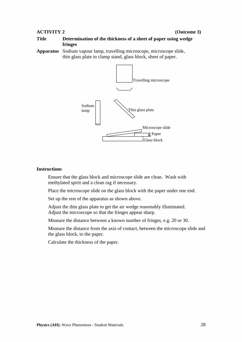
Physics (AH): Wave Phenomena - Student Materials 28
ACTIVITY 2 (Outcome 3)
Title Determination of the thickness of a sheet of paper using wedge
fringes
Apparatus Sodium vapour lamp, travelling microscope, microscope slide,
thin glass plate in clamp stand, glass block, sheet of paper.
Instructions
Ensure that the glass block and microscope slide are clean. Wash with
methylated spirit and a clean rag if necessary.
Place the microscope slide on the glass block with the paper under one end.
Set up the rest of the apparatus as shown above.
Adjust the thin glass plate to get the air wedge reasonably illuminated.
Adjust the microscope so that the fringes appear sharp.
Measure the distance between a known number of fringes, e.g. 20 or 30.
Measure the distance from the axis of contact, between the microscope slide and
the glass block, to the paper.
Calculate the thickness of the paper.
Thin glass plate Sodium
lamp
Travelling microscope
Glass block
Paper
Microscope slide

Physics (AH): Wave Phenomena - Student Materials 29
ACTIVITY 3A (Outcome 3)
Title Determination of wavelength using Young’s slits
Apparatus Laser, double slit, string, screen with sheet of graph paper.
Instructions
Ensure that you obey the safety instructions for the use of lasers.
Set up the apparatus as shown in the diagram.
Use the sheet of graph paper to measure the distance from the central
maximum to the nth
maximum.
Measure the distance D from the double slit to the screen.
Repeat for different nth
maxima.
Determine the slit separation using a travelling microscope.
Use an appropriate format to calculate the mean value of the wavelength of the
laser light.
screen with
graph paper double
slit
laser
D

Physics (AH): Wave Phenomena - Student Materials 30
ACTIVITY 3B (Outcome 3)
Title Determination of wavelength using Young’s slits
Apparatus Laser, double slit, screen with graph paper as a scale.
Instructions
Ensure that you obey the safety instructions for the use of lasers.
Set up the apparatus as shown in the diagram. Use graph paper as a scale on the
screen.
Measure the distance from the central maximum to the nth
maximum.
Measure the distance D from the slit to the screen.
Determine the slit separation using a travelling microscope.
Alter the distance from the slit to the screen and repeat the experiment.
Use an appropriate graphical format to show the relationship between the fringe
separation and the slit to screen distance.
Determine a value for the wavelength of the light used.
screen with
graph paper double
slit
laser
D

Physics (AH): Wave Phenomena - Student Materials 31
ACTIVITY 4 (Outcome 3)
Title Determination of wavelength using Newton’s rings
Apparatus Sodium vapour lamp, travelling microscope, thin glass plate in clamp
stand, biconvex lens of known radius of curvature, glass block
sodium vapour lamp
glass block
biconvex lens
thin glass plate
travelling microscope
Figure 1 Instructions
Ensure that the glass block and microscope slide are clean. Wash with
methylated spirit and a clean rag if necessary.
Place the biconvex lens on the glass block.
Set up the rest of the apparatus as shown in figure 1.
Adjust the microscope so that it is focused on the upper surface of the glass
block and above the centre of the lens.
Adjust the thin glass plate and microscope until interference fringe rings are
seen.
Measure the diameter of a number of rings.
Use an appropriate graphical format to show the relationship between the
diameter of the ring and the ring number.
Determine the wavelength of the light from the graph.
(Due to time constraints it is likely that some staff support may be required to obtain
clear rings. Appropriate theory should be supplied.)

Physics (AH): Wave Phenomena - Student Materials 32

Physics (AH): Summary - Student Materials 1
SUMMARY OF MECHANICS, ELECTRICAL PHENOMENA AND WAVE
PHENOMENA UNITS

Physics (AH): Summary - Student Materials 2

Physics (AH): Summary - Student Materials 3
MECHANICS UNIT
KINEMATIC RELATIONSHIPS AND RELATIVISTIC MOTION
Calculus notation v = ds
dt ; a =
dv
dt =
d2s
dt2
derive v = u +at; v2 = u
2 + 2as; s = ut + ½ at
2
Rest Mass (mo) The mass of an object which is at rest relative to an
observer. (The mass of an object increases with its
velocity).
Relativistic Mass (m) The mass of an object which is travelling at a
velocity comparable to the velocity of light.
m = mo
1 - v2
c2
[equation will be given]
Relativistic Energy E = mc2
ANGULAR MOTION
Angular Displacement () measured in radians. (2 radians = 360°)
Angular Velocity () = d
dt (rad s-1)
Angular Acceleration () = d
dt =
d2
dt2 (rad s-2)
Equations of Motion
CIRCULAR MOTION LINEAR MOTION
[no derivations
required]
[derivations required]
= o + t v = u + a t
= ot + 1
2 t2 s = ut +
1
2 at2
2 = o2 + 2 v2 = u2 + 2as
v = r derivation required]
a = r [no derivation required]
Central Force The force required to maintain a particle in circular
motion.
Central acceleration a = v2
r and a = r
[derivation required]
Central Force equations F = mv2
r and F = m2 r
Physics (AH): Summary - Student Materials 4
ROTATIONAL DYNAMICS
Moment of a Force The magnitude of the moment of a force (or the
turning effect) is force x perpendicular distance
Torque (T) T = F x r where r is the perpendicular distance
from the force to the axis of rotation
Moment of Inertia (I) The moment of inertia depends on the mass and the
distribution of the mass about a fixed axis.
I = m r2 mass m at distance r from axis of rotation
[I = m r2 ( is the ‘sum of’) equation not required]
Torque (T) T = I
Angular Momentum(L) L = I (for a rigid body)
L = mr2 = mrv (for a particle)
Rotational Kinetic Energy Erot = 1
2 I 2 (for a rigid body)
GRAVITATION
Law of Gravitation F = G m1 m2
r2
Gravitational Potential V = - Gm
r (zero of V is at infinity)
Conservative Field The gravitational field is an example of a conservative
field where the total work done moving a mass around
any closed path is zero.
Equipotentials Lines joining points of equal gravitational potential.
Escape Velocity The velocity a projectile must have in order to escape
from a planet's gravitational field.
vesc = 2G M
r [derivation required]
Black Hole A body with a sufficiently high density to make the
escape velocity greater than c, the speed of light.

Physics (AH): Summary - Student Materials 5
SIMPLE HARMONIC MOTION
SHM The unbalanced force, or acceleration, is proportional to
the displacement of the object and acts in the opposite
direction.
SHM Equation d2y
dt2 = - 2y and =
2
T
SHM Solutions y = a sin t if y = 0 at t = 0
y = a cos t if y = a at t = 0
Velocity (dy
dt ) v = ± a2 - y2 a = amplitude of motion.
vmax = ± a and occurs at the centre of the motion,
vmin = 0 at extremes.
Acceleration (d2y
dt2 ) acc = - 2 y
accmax = - 2 a and occurs at y = a.
accmin = 0 at centre.
Energy Ek = 1
2 m 2 (a2 - y2) [derivation required]
Ep = 1
2 m 2 y2 [derivation required]
Etot = Ek + Ep = 1
2 m 2 a2
Damping Damping causes the amplitude of the oscillation to
decay.
WAVE PARTICLE DUALITY
Particles as Waves Particles such as electrons can exhibit wave properties,
such as diffraction.
de Broglie Wavelength = ph (h is the Planck constant and p is momentum)
The Bohr Model of the
Atom
The electrons occupy only certain allowed orbits.
Angular momentum is quantised. Radiation is
emitted when electrons move from higher energy
levels to lower energy levels.
Quantisation of Angular
Momentum mvr =
nh
2
Quantum Mechanics and
Probability
Quantum mechanics provides methods to determine
probabilities.
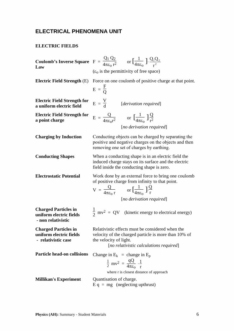
Physics (AH): Summary - Student Materials 6
ELECTRICAL PHENOMENA UNIT
ELECTRIC FIELDS
Coulomb’s Inverse Square
Law
F = Q1 Q2
4o r2 or [1
4o ].
2
21
r
(o is the permittivity of free space)
Electric Field Strength (E) Force on one coulomb of positive charge at that point.
E = F
Q
Electric Field Strength for
a uniform electric field E =
V
d [derivation required]
Electric Field Strength for
a point charge E =
Q
4or2 or [1
4o ].
Q
r2
[no derivation required]
Charging by Induction Conducting objects can be charged by separating the
positive and negative charges on the objects and then
removing one set of charges by earthing.
Conducting Shapes When a conducting shape is in an electric field the
induced charge stays on its surface and the electric
field inside the conducting shape is zero.
Electrostatic Potential Work done by an external force to bring one coulomb
of positive charge from infinity to that point.
V = Q
4o r or [
1
4o ].
Q
r
[no derivation required]
Charged Particles in
uniform electric fields
- non relativistic
1
2 mv2 = QV (kinetic energy to electrical energy)
Charged Particles in
uniform electric fields
- relativistic case
Relativistic effects must be considered when the
velocity of the charged particle is more than 10% of
the velocity of light.
[no relativistic calculations required]
Particle head-on collisions Change in Ek = change in Ep
1
2 mv2 =
4o .
r1
where r is closest distance of approach
Millikan's Experiment Quantisation of charge.
E q = mg (neglecting upthrust)

Physics (AH): Summary - Student Materials 7
ELECTROMAGNETISM
Tesla The tesla is the magnetic induction of a magnetic field
in which a conductor of length one metre, carrying a
current of one ampere perpendicular to the field is
acted on by a force of one newton
Magnetic Induction (B) F = IlB sin ( is the angle between B and l)
The direction of F is perpendicular to the plane
containing B and I.
The Magnetic Induction
around an 'infinite',
straight conductor
B = o I
2 r (o is the permeability of free space)
(r is the perpendicular distance from conductor)
Force between parallel
conductors lF = o
I1 I2
2 r [derivation required]
MOTION IN A MAGNETIC FIELD
Force on charge q, speed
v, in field B: F = q v B sin ( is the angle between v and B)
The direction of F is perpendicular to the plane
containing v and B.
Helical path This is the spiral path followed by a charge when its
velocity makes an angle with the direction of B.
v sin is the component perpendicular to the direction
B, while v cos is the component parallel to the
direction of B.
J.J. Thomson Measured the charge to mass ratio of the electron by
using electric and magnetic deflection of an electron
beam.
‘Crossed’ fields Electric and magnetic fields are applied at right angles
to each other. Charged particles of certain speeds will
pass through undeviated - velocity selector: v = E
B

Physics (AH): Summary - Student Materials 8
SELF-INDUCTANCE
Growth and Decay of
current
The current takes time to grow and decay in a d.c.
circuit containing an inductor
Self-Induction An e.m.f. is induced across a coil when the current in
the coil changes.
Self Inductance (L) e = - L
dI
dt (L is the self inductance of the coil)
Henry The inductance of an inductor is one henry if an e.m.f.
of one volt is induced when the current changes at a
rate of one ampere per second.
Direction of induced
e.m.f.
The direction of the induced e.m.f. is such that it
opposes the change of current. This is known as Lenz's
Law. The negative sign in the above equation indicates
this opposing direction.
Energy stored The work done in building up the current in an inductor
is stored in the magnetic field of the inductor.
The magnetic field can be a source of energy when the
magnetic field is allowed to collapse.
Energy equation E =
1
2 L I2 (energy E stored in inductor L)
Current and frequency in
an inductive circuit
Current is inversely proportional to the frequency in an
inductive circuit.
Reactance The opposition to flow of an alternating current is
called reactance.
C and L in a.c. circuits For an inductor the reactance increases as the
frequency of the a.c. increases.
Conversely the reactance of a capacitor decreases as
the frequency of the a.c. increases.
Uses Inductors can be used to block a.c. signals while
allowing d.c signals to pass. Capacitors can block d.c
signals, but allow high frequency a.c. signals to pass.
Inductors can be used to generate a high voltage when
the magnetic field is allowed to collapse suddenly.
FORCES OF NATURE
Strong Force The force of attraction between nucleons in a nucleus,
with a very short range < 1 x 10-14 m.
Weak Force This is the force associated with -decay.
Quarks Neutrons and protons are made up of quarks.

Physics (AH): Summary - Student Materials 9
WAVE PHENOMENA SUMMARY
WAVES
Wave motion Energy is transferred with no net mass transport.
Travelling Wave The displacement, y, of any point on a travelling wave
in the positive x direction is given by:
y = a sin 2 (ft - x
) [explain not derive]
Intensity of a wave Intensity is directly proportional to (amplitude)2.
Superposition The displacement at a point, due to two or more waves,
is the algebraic sum of the individual displacements.
Phase Difference For two points separated by distance x, the phase
difference is = 2 x
( is the phase angle)
Stationary Wave This wave is produced by the interference of two
identical waves travelling in opposite directions
Nodes These are points of zero displacement on a stationary
wave separated by a distance of
2 .
Antinodes These are points of maximum displacement on a
stationary wave, also separated by
2 .
Doppler Effect This is the change in frequency which is observed
when a source of sound waves moves relative to a
stationary observer.
Apparent frequency when
source of sound moves fobs = fs v
(v - vs)
fobs = fs v
(v + vs)
source moving towards
stationary observer
source moving away from
stationary observer
Apparent frequency when
observer moves fobs = fs v + vo
v
fobs = fs v - vo
v
observer moving towards
stationary source
observer moving away
from stationary source
[derivation of the above expressions for fobs required]

Physics (AH): Summary - Student Materials 10
INTERFERENCE – DIVISION OF AMPLITUDE
Coherent Sources of light Coherent sources must have a constant phase
difference.
Optical path length Optical path length = n x geometrical path length
Optical path difference For optical path lengths S1P and S2P:
(S2P - S1P) = m for constructive interference
(S2P - S1P) = (m + 1
2 ) for destructive interference
Phase difference and
optical path length phase difference =
2 x optical path length
Phase change on
reflection
When light reflects off an optically more dense
medium a phase change of occurs.
Thin Film Destructive interference: 2nt cos r = m
For viewing at near normal incidence 2nt = m
derivation required
Wedge Fringes At normal incidence, fringe separation x is
x = tanθ2 =
DL derivation required
(D is the wedge separation, and L is the wedge length)
Non-Reflective Coatings Thickness of coating, d =
n derivation required
INTERFERENCE – DIVISION OF WAVEFRONT
Point or line source Explain why division of wavefront requires a point or
line source. Describe why division of amplitude can
use an extended source.
Young's Slits Fringe separation x =
dD derivation required
POLARISATION
Plane Polarised Light Linearly polarised light waves consist of vibrations of
the electric field strength vector in one plane only.
Polarisers and Analysers A polariser and analyser held so that their planes of
polarisation are at right angles can prevent the
transmission of light.
Brewster's angle At the polarising angle ip , known as Brewster's angle,
the refracted and reflected rays are separated by 90°.
Brewster’s law n = tan ip [derivation required]