motion control drives - wa and nsw · 2018-09-26 · motion control drives ... no. c2101e-2.0 cw10....
TRANSCRIPT

Motion Control Drives®
No. C2101E-2
CYCLO 6000 Series for Servo Motors
No. C2101E-2.0
CW10

1 221
Our CYCLO® DRIVE LB Series and Standard Series for servo motors have excellent features in addition to compactness, high-durability, long-lifetime, high-efficiency, maintenance-free, and universal mounting (for grease lubrication models) also offered by our CYCLO® DRIVE for general industries.
<<LB Series>>
● Low Backlash Type (0.1° or less)We adopted special tooth profile for LB Series to achievelow backlash naturally without preload.
● Double PowerTraditional reducers use scissors method to achieve low backlash, which enable use of only half of the gearfor power transmission. Our gear utilizes all of the gears for power transmission, which doubles the powertransmission capacity.
What is the scissors method? This is a system of 2 gear tooth (1 pair) pinching the other gear's tooth.
Features, Application
Table 1
Usage of Series Application Control Method
LB Series
Backlash0.1° or less
Conveyor (intermittent, sorting, loading), transportation distribution system (AGV, automatic storage), printing machine, machine tool (ATC, index table, peripheral machine for robots (positioner, slider), packaging machine, textile machine, cutter
Position control
Conveyor, transportation distribution system, printing machine, food processing machine
Speed control
Film winder, intake machine, various testing machine Torque control
Reducers for soft start, high-frequency startup, etc., are also available.
Backlash0.1° or less
Standard backlash
LB SeriesStandard Series
LB SeriesTeamwork of two!
Scissors MethodOne watches TV while the other works hard.
● Features, Application …… 1● Structure, Rating Tables… 3● Nomenclature …………… 4● Ratings …………………… 5
LB Series…………………… 5Standard Series …………… 7
● Selections…………………11
Sta
ndar
d S
erie
s(S
tand
ard
back
lash
)
● Allowable Radial and Axial Load … 13● GD2 ………………………………… 15● Lubrication, Assembling
with Servo Motor…………………… 16● Assembling with Keyless
Type Motor ………………………… 17
Contents
C2101E-2.0.indd 2005/03/03, 11:541

1 221
Features, Application
<<LB Series and Standard Series>>
● Direct Connection with Servo MotorOur stock of adapter plates enables immediate mounting of any type of servo motor.Our direct connection series is directly connected to CYCLO® DRIVE without using adapter plate.
1. Direct ConnectionOur servo motor is directly connected to our CYCLO® DRIVE making the overall length very short.
Fig. 1 Direct Connection Type: CNHM Type
● High Speed InputMaximum 4000 r/min (10 minute cycle at 50% ED) high speed input is possible due to smooth rolling contactmechanism.
● Low InertiaSmall internal moment of inertia enables optimum servo control.
2. Adapter Plate ConnectionAny flange servo motor may be connected directly to our CYCLO® DRIVE by using an adapter plate.
Fig. 2 Plate Direct Connection Type: CNHX Type
Note: Key connection is the standard between servo motor shaft and reducer high speed (input) shaft.
Reducer part Servo motor
Reducer part Adapter plate Servo motor
C2101E-2.0.indd 2005/03/03, 11:542

3 4
Structure, Rating Tables
Adapter Plate Connection
Table 2
No. Part Name1 Slow Speed Shaft
2 Collar
3 Horizontal Casing
4 Slow Speed Shaft Pin
5 Slow Speed Shaft Roller
6 Ring Gear Pin
7 Ring Gear Housing
8 Spacer Ring
9 Cycloid Disc
10 Eccentric Cam
11 High Speed Shaft End Shield
12 High Speed Shaft
13 Adapter Plate
● : StandardTable 3 ▲ : Non-Standard
Frame Size 6065 6075 6085 6095Reduction Ratio 11 15 21 29 43 6 11 15 21 29 43 59 6 11 15 21 29 43 59 87 6 11 15 21 29 43 59 87
LBSeries
Rated Output Torque
N·m 30.0 29.7 51.0 60.0― ― ― ― ― ― ― ―
78.1 187 200kgf·m 3.06 3.03 5.20 6.12 7.96 19.1 20.4
Category ● ● ● ● ▲ ▲ ● ● ● ● ▲ ▲ ― ― ― ― ― ― ― ― ▲ ● ● ● ● ▲ ▲ ▲
Backlash 0.1°or less (0.2°or less for reduction ratio 6).Max. Allowable Input Speed 4000 r/min (10 min cycle, 50% ED)
Frame Size 6105 6115 6125Reduction Ratio 6 11 15 21 29 43 59 87 6 11 15 21 29 43 59 87 6 11 15 21 29 43 59 87
LBSeries
Rated Output Torque
N·m 157 305 300― ― ― ― ― ― ― ―
304 526 592 630kgf·m 16.0 31.1 30.6 31.0 53.6 60.3 64.2
Category ▲ ● ● ● ● ▲ ▲ ▲ ― ― ― ― ― ― ― ― ▲ ● ● ● ● ▲ ▲ ▲
Backlash 0.1°or less (0.2°or less for reduction ratio 6).Max. Allowable Input Speed 4000 r/min (10 min cycle, 50% ED)
Frame Size 6060, 6065 6070, 6075 6080, 6085 6090, 6095Reduction Ratio 6 11 15 21 29 43 6 11 15 21 29 43 59 6 11 15 21 29 43 59 87 6 11 15 21 29 43 59 87
StandardSeries
Category ● ● ● ● ● ● ● ● ● ● ● ● ● ● ● ● ● ● ● ● ● ● ● ● ● ● ● ● ●
Backlash Consult us for each case. Backlash varies depending on the frame size and reduction ratio.Max. Allowable Input Speed 4000 r/min (10 min cycle, 50% ED)
Frame Size 6100, 6105 6110, 6115 6120, 6125Reduction Ratio 6 11 15 21 29 43 59 87 6 11 15 21 29 43 59 87 6 11 15 21 29 43 59 87
StandardSeries
Category ● ● ● ● ● ● ● ● ● ● ● ● ● ● ● ● ● ● ● ● ● ● ● ●
Backlash Consult us for each case. Backlash varies depending on the frame size and reduction ratio.Max. Allowable Input Speed 4000 r/min (10 min cycle, 50% ED)
Note: 1. Rated output torque indicates the mechanical rating of CYCLO® DRIVE. It indicates the allowable value of peak torque applied on the output shaft at the time of normal startup and stop.
2. FINE CYCLO® Series (Catalog No. F2001E) is available for lower backlash requirements. 3. Consult us for middle range reduction ratio of the Standard Series. 4. Consult us for backlash and delivery date of non-standard models.
Fig.3
1 2 3 4 5 6 7 8 9 10 11 12 13
C2101E-2.0.indd 2005/03/03, 11:543

3 4
Nomenclature
Example of Suffix Usage
① Adapter Plate Connection (Foot Mount, Universal Mounting)
●LB Series CNHX-6125-5ALB-15●Standard Series CNHX-6125-5A-15
●LB Series CNHXM-6125-5ALB-15●Standard Series CNHXM-6125-5A-15
② Direct Connection (Foot Mount, Universal Mounting)
●LB Series CNHM-6125-LB-15●Standard Series CNHM-6125-15
CNHX —— 6125 —— 5A LB —— 15
Series Framesize
Motorflange code
Suffix Reductionratio
Nomenclature Example (This is an example for frame size 6125 and below. Mounting direction is universal and the nomenclatures do not change by mounting direction in this case.)
CNHX CNVX CNFX CNHXM
CNHX CNVX CNFX CNHM
(プレート直結方式) (Adapter Plate connection with motor)
(Direct connection with motor)
CNHX CNVX CNFX CNHXM
CNHX CNVX CNFX CNHM
(プレート直結方式) (Adapter Plate connection with motor)
(Direct connection with motor)
Without motor
Without motor
With motor
C2101E-2.0.indd 2005/03/03, 11:544
5 6
Low Backlash
Input Speed 1000r/min
Ratings
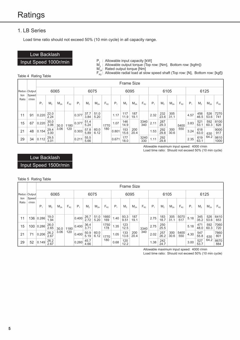
1. LB Series
Load time ratio should not exceed 50% (10 min cycle) in all capacity range.
Table 4 Rating Table
Reduc-tion
Ratio
OutputSpeedr/min
Frame Size
6065 6075 6095 6105 6125
P1 M2 M2A FR2 P1 M2 M2A FR2 P1 M2 M2A FR2 P1 M2 M2A FR2 P1 M2 M2A FR2
11 91 0.220 22.02.24
30.03.06
1180120
0.377 37.73.84
51.05.20
1770180
1.17 11711.9
18719.1
3340340
2.32 23223.6
30531.1
5400550
4.57 45646.5
52653.6
7270741
15 67 0.220 30.03.06 0.377 51.4
5.2460.06.12
1.07 14614.9
20020.4
2.11 28729.3
30030.6
3.83 52153.1
59260.3
8100826
21 48 0.154 29.43.00 0.303 57.8
5.89 0.801 15315.6 1.53 292
29.8 3.24 61863.0 630
64.2
9000917
29 34 0.112 29.53.01 0.211 55.5
5.66 0.671 17718.0
3240330 1.11 292
29.8 2.35 61963.1
98101000
Allowable maximum input speed: 4000 r/minLoad time ratio: Should not exceed 50% (10 min cycle)
Low Backlash
Input Speed 1500r/min
Table 5 Rating Table
Reduc-tion
Ratio
OutputSpeedr/min
Frame Size
6065 6075 6095 6105 6125
P1 M2 M2A FR2 P1 M2 M2A FR2 P1 M2 M2A FR2 P1 M2 M2A FR2 P1 M2 M2A FR2
11 136 0.286 19.01.94
30.03.06
1180120
0.400 26.72.72
51.05.20
1660169 1.40 93.3
9.5118719.1
3340340
2.75 18318.7
30531.1
5070517 5.18 345
35.252653.6
6410653
15 100 0.286 26.02.65 0.400 36.4
3.7160.06.12
1750178 1.35 123
12.520020.4
2.75 25025.5
30030.6
5400550
5.18 47148.0
59260.3
7060720
21 71 0.206 26.22.67 0.400 50.9
5.19 1770180
1.05 13313.6 2.02 257
26.2 4.30 54755.8 630
64.2
7860801
29 52 0.149 26.22.67 0.260 45.7
4.66 0.68 12012.2 1.38 242
24.7 3.00 52753.7
8670884
Allowable maximum input speed: 4000 r/minLoad time ratio: Should not exceed 50% (10 min cycle)
P1 : Allowable input capacity [kW]M2 : Allowable output torque (Top row: [Nm], Bottom row: [kgfm])M2A: Rated output torque [Nm]FR2 : Allowable radial load at slow speed shaft (Top row: [N], Bottom row: [kgf])
C2101E-2.0.indd 2005/03/03, 11:545

5 6
Low Backlash
Input Speed 2000r/min
Table 6 Rating Table
Reduc-tion
Ratio
OutputSpeedr/min
Frame Size
6065 6075 6095 6105 6125
P1 M2 M2A FR2 P1 M2 M2A FR2 P1 M2 M2A FR2 P1 M2 M2A FR2 P1 M2 M2A FR2
11 182 0.350 17.51.78
30.03.06
1100112 0.489 24.4
2.4951.05.20
1510154 1.71 85.5
8.7218719.1
3150321 3.36 168
17.130531.1
4600469 6.34 317
32.352653.6
5820593
15 133 0.350 23.82.43
1180120
0.489 33.43.40
60.06.12
1590162 1.65 113
11.520020.4
3140320 3.36 230
23.430030.6
5030513 6.34 432
44.059260.3
6410653
21 95 0.252 24.02.45 0.489 46.7
4.761670170 1.28 123
12.53180324 2.47 235
24.05160526 5.26 502
51.2 63064.2
7130727
29 69 0.182 23.92.44 0.318 41.9
4.271690172 0.985 129
13.23330339 1.69 223
22.75150525 3.67 484
49.37870802
Allowable maximum input speed: 4000 r/minLoad time ratio: Should not exceed 50% (10 min cycle)
Low Backlash
Input Speed 3000r/min
Table 7 Rating Table
Reduc-tion
Ratio
OutputSpeedr/min
Frame Size
6065 6075 6095 6105 6125
P1 M2 M2A FR2 P1 M2 M2A FR2 P1 M2 M2A FR2 P1 M2 M2A FR2 P1 M2 M2A FR2
11 273 0.465 15.51.58
30.03.06
96097.9 0.650 21.7
2.2151.05.20
1320135 2.27 75.7
7.7218719.1
2750280 4.47 149
15.230531.1
4020410 8.42 281
28.652653.6
5080518
15 200 0.465 21.12.15
1180120
0.650 29.53.01
60.06.12
1390142 2.19 100
10.220020.4
2740279 4.47 203
20.730030.6
4390448 8.42 383
39.059260.3
5600571
21 143 0.335 21.32.17 0.650 41.3
4.211460149 1.71 109
11.12780283 3.28 209
21.3 4500459
6.99 44445.3 630
64.2
6230635
29 103 0.242 21.32.17 0.422 37.1
3.781470150 1.11 97.0
9.893000306 2.24 197
20.1 4.87 42843.6
6870700
Allowable maximum input speed: 4000 r/minLoad time ratio: Should not exceed 50% (10 min cycle)
Note: 1. Allowable output torque (M2)Allowable output torque indicates allowable value of average load torque applied to the output shaft.Allowable input capacity is the necessary input capacity when allowable output torque is at 100%.
2. Rated output torque (M2A)Rated output torque indicates mechanical ratings of CYCLO® DRIVE. It indicates the allowable value of peak torque applied on theoutput shaft at the time of normal startup and stop.
3. GD2
GD2 varies depending on the shaft diameter of the servo motor. Refer to Table 19 and 20 for details.
Ratings
P1 : Allowable input capacity [kW]M2 : Allowable output torque (Top row: [Nm], Bottom row: [kgfm])M2A: Rated output torque [Nm]FR2 : Allowable radial load at slow speed shaft (Top row: [N], Bottom row: [kgf])
C2101E-2.0.indd 2005/03/03, 11:546

7 8
Standard
Input Speed 1000r/min
2. Standard Series
Load time ratio of the Staudard series varies depending on the input speed and capacity range.
Table 8 Rating Table
Reduc-tion
Ratio
OutputSpeed
r/min
Frame Size
6060 6065 6070 6075 6080 6085 6090
P1 M2 M2A FR2 P1 M2 M2A FR2 P1 M2 M2A FR2 P1 M2 M2A FR2 P1 M2 M2A FR2 P1 M2 M2A FR2 P1 M2 M2A FR2
6 167 0.200 10.91.11
24.02.45
90092 0.286 15.6
1.5925.02.55
89291 0.347 18.9
1.9329.73.03
1540157 0.407 22.1
2.2629.73.03
1530156 0.592 32.2
3.2978.58.00
2150219 0.778 42.3
4.3278.58.00
2130217 1.15 62.4
6.3614214.5
3160322
11 91 0.200 20.02.04
1180120
0.286 28.62.91
30.03.06
1170119 0.347 34.6
3.53
45.04.59
1770180
0.407 40.64.14
50.85.18
1770180
0.592 59.16.03 80.0
8.15
2550260 0.778 77.6
7.92 10010.2
2510256 1.15 114
11.6
15015.3
334034015 67 0.176 24.0
2.45 0.220 30.03.06
1180120
0.331 45.04.59 0.407 55.4
5.65
60.06.12
0.588 80.08.15 2560
261
0.735 10010.2 2560
261
1.10 15015.3
21 48 0.126 24.02.45 0.157 30.0
3.06 0.236 45.04.59 0.315 60.0
6.12 0.405 77.27.87
77.27.87 0.405 77.2
7.8777.27.87 0.758 144
14.7
29 34 0.091 24.02.45 0.114 30.0
3.06 0.171 45.04.59 0.228 60.0
6.12 0.304 80.08.16
80.08.15
2500255 0.380 100
10.2
10010.2
2300234 0.570 150
15.33290335
43 23 0.062 24.02.45 0.077 30.0
3.06 0.115 45.04.59 0.154 60.0
6.121660169 0.205 80.0
8.162540259 0.256 100
10.22340239 0.384 150
15.33310337
59 17 ― ― ― ― ― ― ― ― 0.084 45.04.59 0.102 54.6
5.571630166 0.149 79.8
8.132510256 0.187 100
10.2 2310235
0.273 14614.9
14614.9
3300336
87 11 ― ― ― ― ― ― ― ― ― ― ― ― ― ― ― ― 0.090 71.07.24
2520257 0.121 95.6
9.74 0.190 15015.3
15015.3
3310337
Reduc-tion
Ratio
OutputSpeed
r/min
Frame Size
6095 6100 6105 6110 6115 6120 6125
P1 M2 M2A FR2 P1 M2 M2A FR2 P1 M2 M2A FR2 P1 M2 M2A FR2 P1 M2 M2A FR2 P1 M2 M2A FR2 P1 M2 M2A FR2
6 167 1.52 82.58.41
17017.3
3110317 2.35 128
13.017117.4
4590468 3.07 167
17.017117.4
4540463 3.55 193
19.719319.7
5140524 3.55 193
19.719319.7
5140524 5.07 276
28.136637.3
5770588 6.50 354
36.136637.3
5690580
11 91 1.52 15115.4
20020.4
3340340
2.35 23423.9
25025.5
5400550
2.90 29029.5
30831.4
5400550
3.55 35436.1
36036.7
6470660 3.92 391
39.9
42042.8
6420654 5.07 506
51.6 52553.5
7220736 5.26 525
53.562263.4
7200734
15 67 1.47 20020.4 1.84 250
25.5 2.20 30030.6
30030.6
2.65 36036.7
7210735 3.09 420
42.87130727 3.86 525
53.58100826 4.63 630
64.2
63064.2
7990814
21 48 1.05 20020.4 1.31 250
25.5 1.57 30030.6 1.89 360
36.77610776 2.20 420
42.87480762 2.74 522
53.252253.2
9090927 3.31 630
64.28990916
29 34 0.709 18719.0
3220328 0.950 250
25.5 1.14 30030.6 1.37 360
36.77200734 1.60 420
42.86980712 1.98 520
53.052053.0
98101000
2.39 63064.2
9810100043 23 0.478 187
19.03240330 0.641 250
25.5 0.769 30030.6 0.923 360
36.77590774 1.08 420
42.87340748 1.35 525
53.5
52553.5
1.61 63064.2
59 17 0.273 14614.9
14614.9 3300
336
0.467 25025.5 0.539 288
29.429630.2
5290539 0.673 360
36.77610776 0.785 420
42.87420756 0.981 525
53.5 1.18 63064.2
87 11 0.198 15615.9
19519.9 0.317 250
25.5 0.378 29930.4
30030.6
4830492 0.456 360
36.77600775 0.532 420
42.87410755 0.665 525
53.59780997 0.773 610
62.29600979
Allowable maximum input speed: 4000 r/min Load time ratio: Continuous operation possible
Ratings
P1 : Allowable input capacity [kW]M2 : Allowable output torque (Top row: [Nm], Bottom row: [kgfm])M2A: Rated output torque [Nm]FR2 : Allowable radial load at slow speed shaft (Top row: [N], Bottom row: [kgf])
C2101E-2.0.indd 2005/03/03, 11:547

7 8
Standard
Input Speed 1500r/min
Table 9 Rating Table
Reduc-tion
Ratio
OutputSpeed
r/min
Frame Size
6060 6065 6070 6075 6080 6085 6090
P1 M2 M2A FR2 P1 M2 M2A FR2 P1 M2 M2A FR2 P1 M2 M2A FR2 P1 M2 M2A FR2 P1 M2 M2A FR2 P1 M2 M2A FR2
6 250 0.200 7.260.740
24.02.45
78980 0.286 10.4
1.0625.02.55
78480 0.347 12.6
1.2829.73.03
1360139 0.407 14.8
1.5129.73.03
1350138 0.592 21.5
2.1978.58.00
1890193 0.778 28.2
2.8878.58.00
1880192 1.15 41.6
4.2414214.5
2780283
11 136 0.200 13.31.36
1180120
0.286 19.01.94
30.03.06
1180120
0.347 23.12.35
45.04.59
1680171 0.407 27.1
2.7650.85.18
1660169 0.592 39.4
4.02 80.08.15
2250229 0.778 51.7
5.27 10010.2
2230227 1.15 76.3
7.78
15015.3
3340340
15 100 0.200 18.11.85 0.286 26.0
2.65 0.347 31.43.20
1770180
0.407 36.93.77
60.06.12
1750178 0.592 53.7
5.482490254 0.778 70.6
7.202460251 1.15 104
10.6
21 71 0.189 24.02.45 0.234 29.7
3.03 0.320 40.74.15 0.407 51.7
5.27 1770180
0.478 60.76.19
77.27.87
2560261
0.550 69.97.12
77.27.87
2540259 0.758 96.2
9.81
29 52 0.110 19.31.97 0.166 29.1
2.97 0.226 39.64.04 0.286 50.2
5.12 0.340 59.66.08
80.08.15
0.467 81.98.35
10010.2
2480253 0.625 110
11.2
43 35 0.090 23.42.39 0.113 29.4
3.00 0.170 44.14.50 0.226 58.8
5.991690172 0.250 65.0
6.63 0.294 76.47.79
2560261 0.435 113
11.5
59 25 ― ― ― ― ― ― ― ― 0.100 35.73.64 0.136 48.4
4.931720175 0.185 65.9
6.72 0.234 83.48.50
2480253 0.309 110
11.214614.9
87 17 ― ― ― ― ― ― ― ― ― ― ― ― ― ― ― ― 0.090 47.44.83 0.121 63.7
6.492560261 0.211 111
11.315015.3
Reduc-tion
Ratio
OutputSpeed
r/min
Frame Size
6095 6100 6105 6110 6115 6120 6125
P1 M2 M2A FR2 P1 M2 M2A FR2 P1 M2 M2A FR2 P1 M2 M2A FR2 P1 M2 M2A FR2 P1 M2 M2A FR2 P1 M2 M2A FR2
6 250 1.52 55.05.61
17017.3
2760281 2.35 85.2
8.6917117.4
4040412 3.18 115
11.817117.4
4000408 3.55 129
13.119319.7
4540463 3.92 142
14.519319.7
4520461 5.07 184
18.836637.3
5100520 6.96 253
25.836637.3
5030513
11 136 1.52 10110.3
20020.4
3340340
2.35 15615.9
25025.5
5100520 3.18 212
21.630831.4
5030513 3.55 236
24.1
36036.7
5730584 3.92 261
26.6
42042.8
5710582 5.07 337
34.4 52553.5
6420654 5.92 394
40.262263.4
6360648
15 100 1.52 13714.0 2.35 213
21.7
5400550
3.18 28829.4
30030.6
5400550
3.55 32232.8
6290641 3.90 354
36.16250637 5.07 460
46.97070721 5.92 537
54.8
63064.2
7000714
21 71 1.52 19219.6 1.93 245
25.0 2.34 29730.3 2.72 346
35.26780691 3.11 395
40.36720685 3.96 503
51.352253.2
7900805 4.88 620
63.27790794
29 52 0.784 13714.0
3320338 1.21 212
21.6 1.59 27928.4 1.90 333
34.07170731 2.22 390
39.77120726 2.96 519
53.052053.0
8670884 3.59 630
64.28570874
43 35 0.603 15716.0
3300336 0.780 203
20.7 1.08 28128.6 1.30 338
34.5
7610776
1.52 39440.2
7550770 1.91 497
50.7
52553.5
98101000
2.38 61963.1
9780997
59 25 0.342 12212.4
14614.9
3340340 0.516 184
18.8 0.694 24825.3
29630.2 0.859 307
31.3 1.01 36036.7
7610776 1.30 464
47.3 1.62 57859.0
98101000
87 17 0.270 14214.5
19519.9
3330339 0.433 228
23.2 0.516 27227.7
30030.6 0.661 348
35.5 0.758 39940.7
7560771 0.944 497
50.7 1.05 55356.4
9720991
Allowable maximum input speed: 4000 r/min Load time ratio: Continuous operation possible
Note: 1. Allowable output torque (M2)Allowable output torque indicates allowable value of average load torque applied to the output shaft.Allowable input capacity is the necessary input capacity when allowable output torque is at 100%.
2. Rated output torque (M2A)Rated output torque indicates mechanical ratings of CYCLO® DRIVE. It indicates the allowable value of peak torque applied on theoutput shaft at the time of normal startup and stop.
3. GD2
GD2 varies depending on the shaft diameter of the servo motor. Refer to Table 19 and 20 for details.
Ratings
P1 : Allowable input capacity [kW]M2 : Allowable output torque (Top row: [Nm], Bottom row: [kgfm])M2A: Rated output torque [Nm]FR2 : Allowable radial load at slow speed shaft (Top row: [N], Bottom row: [kgf])
C2101E-2.0.indd 2005/03/03, 11:548
9 10
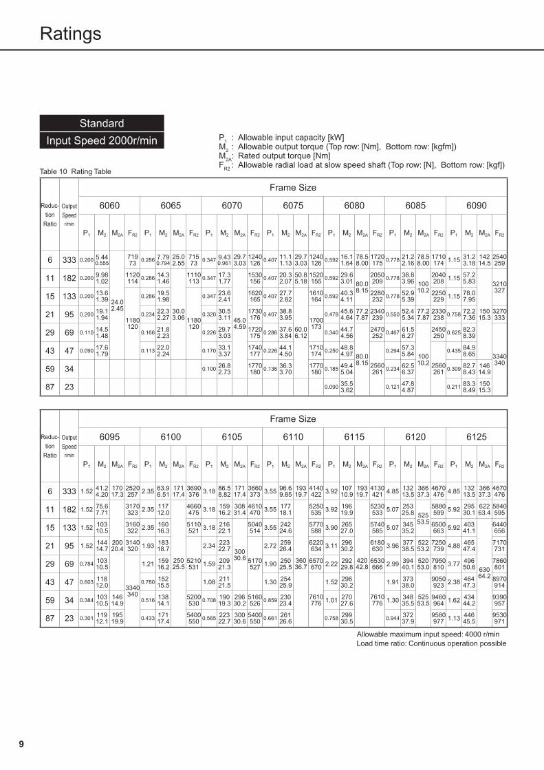
Standard
Input Speed 2000r/min
Table 10 Rating Table
Reduc-tion
Ratio
OutputSpeedr/min
Frame Size
6060 6065 6070 6075 6080 6085 6090
P1 M2 M2A FR2 P1 M2 M2A FR2 P1 M2 M2A FR2 P1 M2 M2A FR2 P1 M2 M2A FR2 P1 M2 M2A FR2 P1 M2 M2A FR2
6 333 0.200 5.440.555
24.02.45
71973 0.286 7.79
0.79425.02.55
71573 0.347 9.43
0.96129.73.03
1240126 0.407 11.1
1.1329.73.03
1240126 0.592 16.1
1.6478.58.00
1720175 0.778 21.2
2.1678.58.00
1710174 1.15 31.2
3.1814214.5
2540259
11 182 0.200 9.981.02
1120114 0.286 14.3
1.46
30.03.06
1110113 0.347 17.3
1.77
45.04.59
1530156 0.407 20.3
2.0750.85.18
1520155 0.592 29.6
3.01 80.08.15
2050209 0.778 38.8
3.96 10010.2
2040208 1.15 57.2
5.83
15015.3
3210327
15 133 0.200 13.61.39
1180120
0.286 19.51.98
1180120
0.347 23.62.41
1620165 0.407 27.7
2.82
60.06.12
1610164 0.592 40.3
4.112280232 0.778 52.9
5.392250229 1.15 78.0
7.95
21 95 0.200 19.11.94 0.234 22.3
2.27 0.320 30.53.11
1730176 0.407 38.8
3.95 1700173
0.478 45.64.64
77.27.87
2340239 0.550 52.4
5.3477.27.87
2330238 0.758 72.2
7.363270333
29 69 0.110 14.51.48 0.166 21.8
2.23 0.226 29.73.03
1720175 0.286 37.6
3.84 0.340 44.74.56
80.08.15
2470252 0.467 61.5
6.27
10010.2
2450250 0.625 82.3
8.39
3340340
43 47 0.090 17.61.79 0.113 22.0
2.24 0.170 33.13.37
1740177 0.226 44.1
4.501710174 0.250 48.8
4.97
2560261
0.294 57.35.84
2560261
0.435 84.98.65
59 34 ― ― ― ― ― ― ― ― 0.100 26.82.73
1770180 0.136 36.3
3.701770180 0.185 49.4
5.04 0.234 62.56.37 0.309 82.7
8.4314614.9
87 23 ― ― ― ― ― ― ― ― ― ― ― ― ― ― ― ― 0.090 35.53.62 0.121 47.8
4.87 0.211 83.38.49
15015.3
Reduc-tion
Ratio
OutputSpeed
r/min
Frame Size
6095 6100 6105 6110 6115 6120 6125
P1 M2 M2A FR2 P1 M2 M2A FR2 P1 M2 M2A FR2 P1 M2 M2A FR2 P1 M2 M2A FR2 P1 M2 M2A FR2 P1 M2 M2A FR2
6 333 1.52 41.24.20
17017.3
2520257 2.35 63.9
6.5117117.4
3690376 3.18 86.5
8.8217117.4
3660373 3.55 96.6
9.8519319.7
4140422 3.92 107
10.919319.7
4130421 4.85 132
13.536637.3
4670476 4.85 132
13.536637.3
4670476
11 182 1.52 75.67.71
20020.4
3170323 2.35 117
12.0
25025.5
4660475 3.18 159
16.230831.4
4610470 3.55 177
18.1
36036.7
5250535 3.92 196
19.9
42042.8
5230533 5.07 253
25.8 52553.5
5880599 5.92 295
30.162263.4
5840595
15 133 1.52 10310.5
3160322 2.35 160
16.35110521 3.18 216
22.1
30030.6
5040514 3.55 242
24.65770588 3.90 265
27.05740585 5.07 345
35.26500663 5.92 403
41.1
63064.2
6440656
21 95 1.52 14414.7
3140320 1.93 183
18.7
5210531
2.34 22322.7
5170527
2.72 25926.4
6220634 3.11 296
30.26180630 3.96 377
38.552253.2
7250739 4.88 465
47.47170731
29 69 0.784 10310.5
3340340
1.21 15916.2 1.59 209
21.3 1.90 25025.5
6570670 2.22 292
29.86530666 2.99 394
40.152053.0
7950810 3.77 496
50.67860801
43 47 0.603 11812.0 0.780 152
15.5 1.08 21121.5 1.30 254
25.9
7610776
1.52 29630.2
7610776
1.91 37338.0
52553.5
9050923 2.38 464
47.38970914
59 34 0.384 10310.5
14614.9 0.516 138
14.15200530 0.708 190
19.329630.2
5160526 0.859 230
23.4 1.01 27027.6 1.30 348
35.59460964 1.62 434
44.29390957
87 23 0.301 11912.1
19519.9 0.433 171
17.45400550 0.565 223
22.730030.6
5400550 0.661 261
26.6 0.758 29930.5 0.944 372
37.99580977 1.13 446
45.59530971
Allowable maximum input speed: 4000 r/min Load time ratio: Continuous operation possible
Ratings
P1 : Allowable input capacity [kW]M2 : Allowable output torque (Top row: [Nm], Bottom row: [kgfm])M2A: Rated output torque [Nm]FR2 : Allowable radial load at slow speed shaft (Top row: [N], Bottom row: [kgf])
C2101E-2.0.indd 2005/03/03, 11:549

9 10
Standard
Input Speed 3000r/min
Table 11 Rating Table
Reduc-tion
Ratio
OutputSpeed
r/min
Frame Size
6060 6065 6070 6075 6080 6085 6090
P1 M2 M2A FR2 P1 M2 M2A FR2 P1 M2 M2A FR2 P1 M2 M2A FR2 P1 M2 M2A FR2 P1 M2 M2A FR2 P1 M2 M2A FR2
6 500 0.200 3.630.370
24.02.45
63064 0.259 4.70
0.47925.02.55
62864 0.259 4.70
0.47929.73.03
1100112 0.259 4.70
0.47929.73.03
1100112 0.565 10.2
1.0478.58.00
1510154 0.565 10.2
1.0478.58.00
1510154 0.874 15.9
1.6214214.5
2240228
11 273 0.200 6.650.678
980100 0.286 9.52
0.970
30.03.06
97499 0.347 11.5
1.18
45.04.59
1350138 0.407 13.5
1.3850.85.18
1350138 0.592 19.7
2.01 80.08.15
1810185 0.778 25.9
2.64 10010.2
1790182 1.15 38.1
3.88
15015.3
2820287
15 200 0.200 9.070.925
1180120
0.286 13.01.32
1180120
0.347 15.71.61
1440147 0.407 18.5
1.88
60.06.12
1430146 0.592 26.9
2.742000204 0.778 35.3
3.601990203 1.15 52.0
5.302830288
21 143 0.200 12.71.30 0.234 14.8
1.51 0.320 20.32.07
1530156 0.407 25.8
2.63 1510154
0.478 30.43.10
77.27.87
2050209 0.550 34.9
3.5677.27.87
2050209 0.758 48.1
4.902880294
29 103 0.110 9.650.984 0.166 14.5
1.48 0.226 19.82.02
1520155 0.286 25.1
2.56 0.340 29.83.04
80.08.15
2170221 0.467 41.0
4.18
10010.2
2160220 0.625 54.8
5.593070313
43 70 0.090 11.71.19 0.113 14.7
1.50 0.170 22.02.24
1530156 0.226 29.4
3.001520155 0.250 32.5
3.322520257 0.294 38.2
3.892510256 0.435 56.6
5.77
334034059 51 ― ― ― ― ― ― ― ― 0.100 17.8
1.811590162 0.136 24.2
2.471580161 0.185 32.9
3.35 2560261
0.234 41.74.25 2560
261
0.309 55.15.62
14614.9
87 35 ― ― ― ― ― ― ― ― ― ― ― ― ― ― ― ― 0.090 23.72.42 0.121 31.9
3.25 0.211 55.55.66
15015.3
Reduc-tion
Ratio
OutputSpeed
r/min
Frame Size
6095 6100 6105 6110 6115 6120 6125
P1 M2 M2A FR2 P1 M2 M2A FR2 P1 M2 M2A FR2 P1 M2 M2A FR2 P1 M2 M2A FR2 P1 M2 M2A FR2 P1 M2 M2A FR2
6 500 0.961 17.41.78
17017.3
2240228 2.35 42.6
4.3417117.4
3240330 3.18 57.7
5.8817117.4
3220328 3.55 64.4
6.5719319.7
3640371 3.92 71.1
7.2519319.7
3630370
11 273 1.52 50.45.14
20020.4
2800285
2.35 78.17.96
25025.5
4100418 3.18 106
10.830831.4
4070415 3.55 118
12.0
36036.7
4630472 3.92 130
13.3
42042.8
4620471 5.07 169
17.2 52553.5
5190529 5.92 197
20.162263.4
5160526
15 200 1.52 68.77.00 2.35 106
10.84500459 3.18 144
14.7
30030.6
4460455 3.55 161
16.45100520 3.90 177
18.05080518 5.07 230
23.55740585 5.92 269
27.4
63064.2
5700581
21 143 1.52 96.29.81 1.93 122
12.44590468 2.34 148
15.14570466 2.72 173
17.65490560 3.11 198
20.15470558 3.96 252
25.652253.2
6400652 4.88 310
31.66350647
29 103 0.784 68.77.00
3050311 1.21 106
10.8 4580467
1.59 13914.2 4550
464
1.90 16717.0
5790590 2.22 195
19.95760587 2.99 262
26.752053.0
7010715 3.77 330
33.66950708
43 70 0.603 78.47.99
3340340
0.780 10110.3 1.08 141
14.3 1.30 16917.2
6970710 1.52 197
20.16940707 1.91 249
25.3
52553.5
7970812 2.38 310
31.67920807
59 51 0.384 68.66.99
14614.9 0.516 92.1
9.394560465 0.708 126
12.929630.2
4540463 0.859 153
15.6 7610776
1.01 18018.4 7610
776
1.30 23223.7
8320848 1.62 289
29.58280844
87 35 0.301 79.28.08
19519.9 0.433 114
11.64980508 0.565 149
15.230030.6
4960506 0.661 174
17.7 0.758 19920.3 0.944 248
25.38420858 1.13 297
30.38390855
Allowable maximum input speed: 4000 r/min Load time ratio: Should not exceed 50% (10 min cycle)
*Always use within 80% of the allowable input capacity and rated output torque indicated in the above table when using for continuous operation.
Note: 1. Allowable output torque (M2)Allowable output torque indicates allowable value of average load torque applied to the output shaft.
Allowable input capacity is the necessary input capacity when allowable output torque is at 100%. 2. Rated output torque (M2A) Rated output torque indicates mechanical ratings of CYCLO® DRIVE. It indicates the allowable value of peak torque applied on the
output shaft at the time of normal startup and stop. 3. GD2
GD2 varies depending on the shaft diameter of the servo motor. Refer to Table 19 and 20 for details.
Ratings
P1 : Allowable input capacity [kW]M2 : Allowable output torque (Top row: [Nm], Bottom row: [kgfm])M2A: Rated output torque [Nm]FR2 : Allowable radial load at slow speed shaft (Top row: [N], Bottom row: [kgf])
C2101E-2.0.indd 2005/03/03, 11:5410

11 12
Selections
1. Flowchart and Formula for Selection
Evaluate load characteristics.
Determine load factor (Table 13).
Calculate average load torque (TE).
Determine reduction ratio (Z).
Refer to rating table (page 5~10).
TRO≧TE
TRO:Allowable output torque at maximum input speed
Select temporary frame size.
Contemplate input speed.
Calculate %ED.
Refer to rating table (page 5~10).
Check allowable maximum input speed.Check load time ratio.
Selection complete.
Contemplate startup stop peak torque (TP).
Refer to rating table (page 5~10).
Rated output torque≧TP Fn FSF
Determine frame size.
Contemplate radial load and axial load.
Allowable load ≧ Actual load
NO
NO
NO
NO
(Raise frame size)
Refer to Table 15~18, formula 4~6.
Raise frame size or lower average load torque TE.( )
Raise frame size or lower peak torque TP.( ) ( )
N : Maximum input speedtA : Acceleration time TA : Acceleration peak torquetR : Normal running time TR : Torque during normal runningtB : Deceleration time TB : Peak torque at brakingtO : Total running time TP : Peak Torque (TA or TB)tP : Standstill time (Larger torque of either TA or TB)
T : Time/Cycle
Load Pattern
Inpu
t spe
ed
Time
Load
torq
ue
Time
C2101E-2.0.indd 2005/03/03, 11:5411

11 12
Evaluate load characteristics.
Determine load factor (Table 13).
Calculate average load torque (TE).
Determine reduction ratio (Z).
Refer to rating table (page 5~10).
TRO≧TE
TRO:Allowable output torque at maximum input speed
Select temporary frame size.
Contemplate input speed.
Calculate %ED.
Refer to rating table (page 5~10).
Check allowable maximum input speed.Check load time ratio.
Selection complete.
Contemplate startup stop peak torque (TP).
Refer to rating table (page 5~10).
Rated output torque≧TP Fn FSF
Determine frame size.
Contemplate radial load and axial load.
Allowable load ≧ Actual load
NO
NO
NO
NO
(Raise frame size)
Refer to Table 15~18, formula 4~6.
Raise frame size or lower average load torque TE.( )
Raise frame size or lower peak torque TP.( ) ( )
Table 12 Fn Startup frequency factor
Startup frequency Factor1~2 times/min 1.0
3~5 times/min 1.1
6~9 times/min 1.2
*Consult us when the startup frequency is other than the above.
Table 13 FSF Load factor
Load condition
Operation time
U(Uniform
shock)
M(Light shock)
H(Heavy
shock)
~10 hours/day 1.0 1.0 1.4
24 hours/day 1.2 1.35 1.6
2. Selection Example
<Applications> Low backlash specification for transportation vehicle drive<Specification> TA : Acceleration peak torque 8.0kgf·m n : Maximum output speed 69r/min
TR: Torque during normal running 0.7kgf·m tA : Acceleration time 0.5secTB : Peak torque at braking 4.9kgf·m tR : Normal running time 6.5sec
tB : Deceleration time 1.0sec tO: Total running time 8.0sec tP : Standstill time 8.0sec T : Time/Cycle 16.0sec
Radial load 200kgf is applied to the midpoint of slow speed shaft. Rated seed of servomotor is 2000r/min10 hours/day operation
<Calculations> ● Determine load factor Fn = 1.1 FSF = 1.0 (Table 12~14)
● Calculate average load torque TE = = 3.2(kgf·m)
(Formula 1)
● Determine reduction ratio (Formula 2)
● Calculate allowable output torque at maximum input speed TRO = 13.2(kgf·m)> 3.2(kgf·m)→ Select temporary frame size 6095#-29
(P.5~P.10)
● Calculate %ED %ED = × 100=50% (Formula 3)
● Check maximum input speed 2000(r/min) at 50%ED< 4000 (r/min) at 50% ED (P.5~P.10)
● Check peak torque at startup stop 8.0(kgf·m)× 1.1× 1.0= 8.8(kgf·m)< 20.4(kgf·m) (P.5~P.10)
● Allowable radial load of slow speed shaft with factor Pro = 339(kgf), Lf = 1.0, Cf = 1.25, Fs = 1.2in consideration.
= 226(kgf)>200(kgf) (Table 15~18, Formula 4)
Frame size 6095#-29 from the contemplation above.
Maximum operation cycle is 10 minutes when calculating % ED. Assign T=10 (min) when calculating for cycle over this time.
692000
1
29=Z=
ProLf×Cf×Fs
339=
1.0×1.25×1.2
816
0.3×8.010/3×0.5+0.710/3×6.5+ ×4.910/3×11
212
×0.5+6.5+ ×1.012
12
Average load torque TE = …… (Formula 1)
Reduction ratio Z = …………………………… (Formula 2)
% ED %ED = × 100 ……………………………………… (Formula 3)toT
・TA10/3・tA+TR
10/3・tR+ ・TB10/3・tB
・tA+tR+ ・tB12
0.3
12
12 1
2
Output speed
Maximum input speed
Table 14 Load Characteristics Table for Machinery
Transportation & Distribution Machines
Conveyor (uniform load)Apron, Assembly,Belt, Bucket, Chain, Oven,Screw
Conveyor (heavy load, intermittent) Apron, Assembly, Belt, MBucketSorting apparatus MAGV M
Peripheral equipment for robotsSlider MPositioner M
Consult us for applications for * and the ones not indicated above.
Metal processing machineTapping machine HPunch press (gear operation) HPlaner HBending machine MATC MGeneral machine tools *
Printing machine *Textile, Spinning and Weaving
Batcher, Calendar, Card, Drying can, Dryer, Dyeing machine, Mangle, Napper, Pad, Slasher, Soaper, Winder,Spinning machine, Stenter, Fabric washing machine, Fabric finishing machine Fabric washing machine, Pad, Stenter, Dryer, Calendar, etc.
U
M
Selections
C2101E-2.0.indd 2005/03/03, 11:5412

13 14
Allowable Radial and Axial Load
Do not exceed the allowable value for radial and axial load when attaching gear or pulley to the CYCLO® DRIVE
Radial and Axial Load of the Slow Speed ShaftCheck the radial and axial load for slow speed shaft following the formulas 4~6.
Radial load Pr Pr = [kgf] …………… (Formula 4)
Axial load Pa Pa≦ [kgf] ………………………… (Formula 5)
When radial and axial load coexists ・Cf・Fs≦ 1……… (Formula 6)
Pr : Actual radial load [N, kgf]T旭 : Actual transmitted torque [N·m, kgf·m] on slow speed
shaft of the reducerR : Pitch circle radius [m] of sprocket, gear, pulley, etc.Pro : Allowable radial load [N, kgf] (Refer to the Rating Table)Pa : Actual axial load [N, kgf]Pao: Allowable axial load [N, kgf] (Table 18)Lf : Load location factor (Table 17)Cf : Coupling factor (Table 15)Fs : Shock factor (Table 16)
Table 15 Coupling Factor Cf
Coupling Method CfChain 1
Gears 1.25
V-Belt 1.5
Table 16 Shock Factor Fs
Degree of Shock FsPractically no shock 1
Light shock 1~1.2
Severe shock 1.4~1.6
Table 17 Load Location Factor Lf on Slow Speed Shaft
LmmFrame Size ~5 10 15 20 25 30 35 40 45 50
6060, 6065 0.83 0.94 1.19 1.56 ― ― ― ― ― ―
6070, 6075 0.82 0.91 1.00 1.29 1.59 1.88 ― ― ― ―
6080, 6085 0.81 0.87 0.94 1.03 1.28 1.54 1.80 ― ― ―
6090, 6095 0.86 0.92 0.97 1.13 1.38 1.64 1.90 ― ― ―
6100, 6105 0.86 0.92 0.97 1.13 1.38 1.64 1.90 ― ― ―
6110, 6115 0.78 0.84 0.90 0.96 1.02 1.08 1.19 1.36 1.53 ―
6120, 6125 ― 0.82 0.87 0.92 0.97 1.08 1.25 1.42 1.59 1.76
LLo
Pr
Lf=1 when L=Lo/2.
Pr・LfPro +
PaPao
T旭
R≦
ProLf・Cf・Fs
PaoCf・Fs
C2101E-2.0.indd 2005/03/03, 11:5413

13 14
Table 18 Allowable Axial Load Pao on Slow Speed Shaft [N] / [kgf] (Cf, Lf, Fs = 1)
Output Speedr/min
Frame Size~10 15 20 25 30 35 40 50 60 80 100 125 150 200 250 300
6060, 6065 294.330
294.330
294.330
294.330
294.330
294.330
294.330
294.330
294.330
294.330
294.330
294.330
294.330
294.330
―
―
―
―
6070, 6075 784.880
784.880
784.880
784.880
784.880
784.880
784.880
784.880
784.880
784.880
784.880
784.880
784.880
784.880
784.880
784.880
6080, 6085 981100
981100
981100
981100
981100
981100
981100
981100
981100
981100
981100
981100
981100
981100
981100
981100
6090, 6095 981100
981100
981100
981100
981100
981100
981100
981100
981100
981100
981100
981100
981100
981100
981100
981100
6100, 6105 1470150
1470150
1470150
1470150
1470150
1470150
1470150
1470150
1470150
1470150
1470150
1470150
1470150
1470150
1470150
1470150
6110, 6115 1470150
1470150
1470150
1470150
1470150
1470150
1470150
1470150
1470150
1470150
1470150
1470150
1470150
1470150
1470150
1470150
6120, 6125 2940300
2940300
2940300
2940300
2940300
2940300
2940300
2940300
2940300
2940300
2940300
2940300
2940300
2770282
2500255
2390244
Calculate detailed intermediate value using interpolation method as below.[Example of Interpolation Method Calculation]Radial load location factor Radial load location factor of slow speed shaft for frame size 6075 with L= 18mm is:
Allowable axial loadAllowable axial load of slow speed shaft for frame size 6125 with output speed 180 r/min is:
1.29-1.0020-15
1.00 + × (18-15) = 1.17
300-282
200-150282 + × (200-180) = 289 [kgf]
Allowable Radial and Axial Load
C2101E-2.0.indd 2005/03/03, 11:5414
15 16
GD2 (on High Speed Shaft)
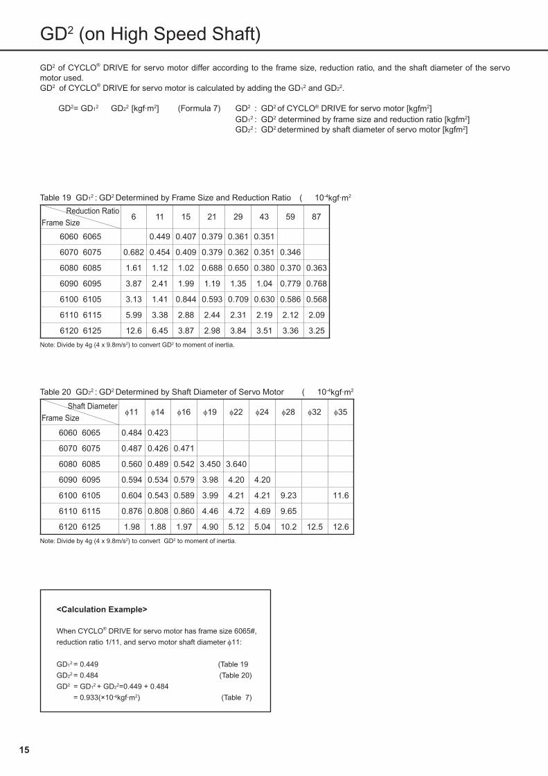
GD2 of CYCLO® DRIVE for servo motor differ according to the frame size, reduction ratio, and the shaft diameter of the servo motor used.GD2 of CYCLO® DRIVE for servo motor is calculated by adding the GD12 and GD22.
GD2= GD12+ GD22 [kgf·m2] ……(Formula 7) GD2 : GD2 of CYCLO® DRIVE for servo motor [kgfm2]GD12 : GD2 determined by frame size and reduction ratio [kgfm2]GD22 : GD2 determined by shaft diameter of servo motor [kgfm2]
Table 19 GD12 : GD2 Determined by Frame Size and Reduction Ratio (× 10-4kgf·m2)
Reduction RatioFrame Size
6 11 15 21 29 43 59 87
6060 6065 0.449 0.407 0.379 0.361 0.351
6070 6075 0.682 0.454 0.409 0.379 0.362 0.351 0.346
6080 6085 1.61 1.12 1.02 0.688 0.650 0.380 0.370 0.363
6090 6095 3.87 2.41 1.99 1.19 1.35 1.04 0.779 0.768
6100 6105 3.13 1.41 0.844 0.593 0.709 0.630 0.586 0.568
6110 6115 5.99 3.38 2.88 2.44 2.31 2.19 2.12 2.09
6120 6125 12.6 6.45 3.87 2.98 3.84 3.51 3.36 3.25
Note: Divide by 4g (4 x 9.8m/s2) to convert GD2 to moment of inertia.
<Calculation Example>
When CYCLO® DRIVE for servo motor has frame size 6065#,
reduction ratio 1/11, and servo motor shaft diameter φ11:
GD12 = 0.449 (Table 19)
GD22 = 0.484 (Table 20)
GD2 = GD12 + GD22=0.449 + 0.484
= 0.933(×10-4kgf·m2) (Table 7)
Table 20 GD22 : GD2 Determined by Shaft Diameter of Servo Motor (× 10-4kgf·m2)
Shaft DiameterFrame Size
φ11 φ14 φ16 φ19 φ22 φ24 φ28 φ32 φ35
6060 6065 0.484 0.423
6070 6075 0.487 0.426 0.471
6080 6085 0.560 0.489 0.542 3.450 3.640
6090 6095 0.594 0.534 0.579 3.98 4.20 4.20
6100 6105 0.604 0.543 0.589 3.99 4.21 4.21 9.23 11.6
6110 6115 0.876 0.808 0.860 4.46 4.72 4.69 9.65
6120 6125 1.98 1.88 1.97 4.90 5.12 5.04 10.2 12.5 12.6
Note: Divide by 4g (4 x 9.8m/s2) to convert GD2 to moment of inertia.
C2101E-2.0.indd 2005/03/03, 11:5415

15 16
Lubrication
1. Lubrication Method
Both LB and Standard Series are shipped filled with grease, ready to use.
Table 21 Common Grease for Horizontal and Vertical Types
Reduction RatioFrame Size
6 11 15 21 29 43 59 87
6060 6065
6070 6075
6080 6085
Grease lubrication (maintenance-free type)(MF)
6090 6095
6100 6105
6110 6115
6120 6125
2. Lubricant
(1) Filled with long-lifetime grease, both LB and Standard Series require infrequent lubricant replacement. However, replacement every 20,000 hours or every 4 to 5 years will provide even longer lifetime.
(2) Do not use grease other than the ones indicated in Table 22.(3) Consult us when operating constantly at temperature range exceeding 0~40℃ .
Table 22
Ambient Temperature (℃)
Maintenance-Free Type
LB Series Standard Series
0~40Shell Oil
Shell Alvania GreaseRA
Assembling with Servo Motor(1) Apply grease to the servo motor shaft in advance for smooth fitting to the high speed hollow shaft.(2) Align the motor shaft key with the hollow shaft key way.(3) Always check whether the spigot of the servo motor is exactly matching the spigot of adapter plate when
tightening servo motor and adapter plate with bolt. Tightening bolt with uneven fitting may damage the internals.
C2101E-2.0.indd 2005/03/03, 11:5416
17 18
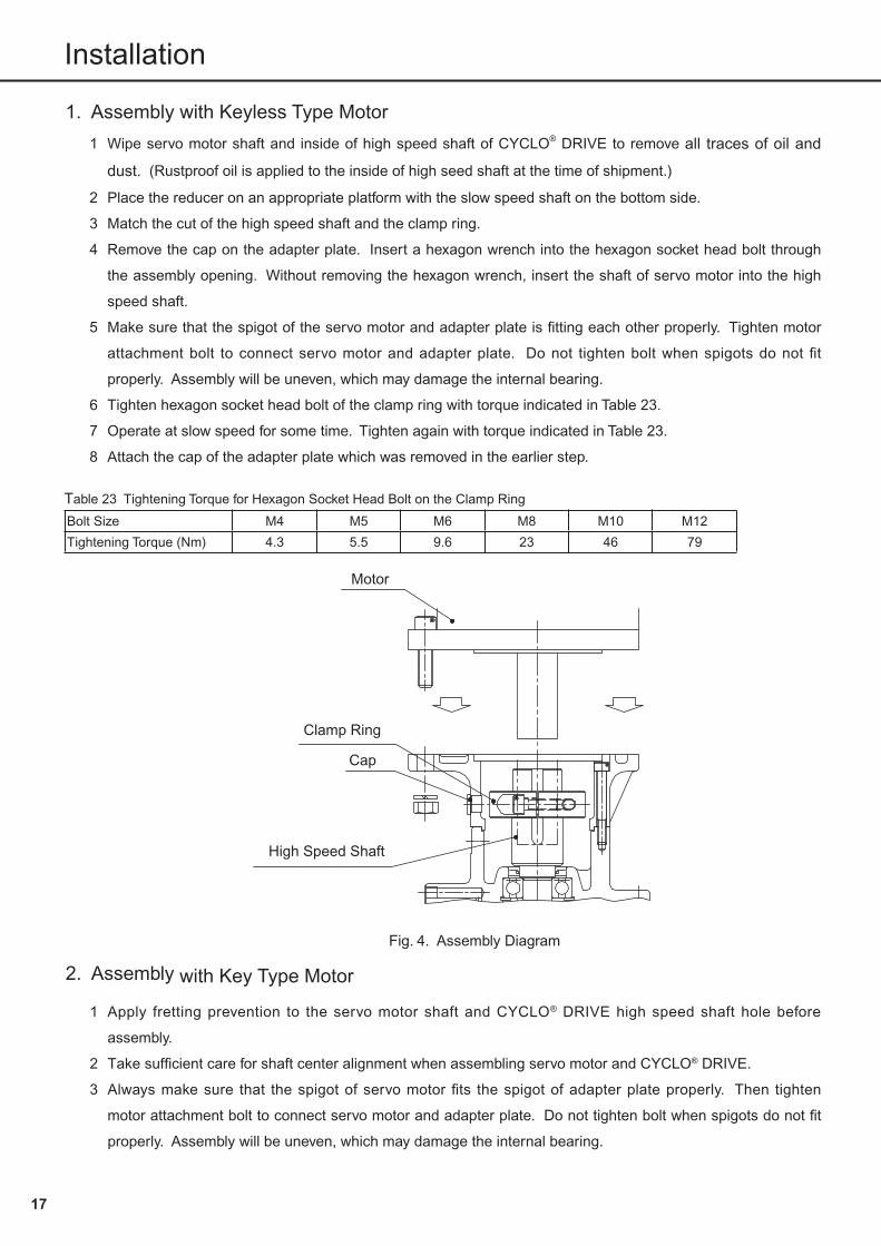
Installation
1. Assembly with Keyless Type Motor(1) Wipe servo motor shaft and inside of high speed shaft of CYCLO® DRIVE to remove all traces of oil and
dust. (Rustproof oil is applied to the inside of high seed shaft at the time of shipment.)
(2) Place the reducer on an appropriate platform with the slow speed shaft on the bottom side.
(3) Match the cut of the high speed shaft and the clamp ring.
(4) Remove the cap on the adapter plate. Insert a hexagon wrench into the hexagon socket head bolt through
the assembly opening. Without removing the hexagon wrench, insert the shaft of servo motor into the high
speed shaft.
(5) Make sure that the spigot of the servo motor and adapter plate is fitting each other properly. Tighten motor
attachment bolt to connect servo motor and adapter plate. Do not tighten bolt when spigots do not fit
properly. Assembly will be uneven, which may damage the internal bearing.
(6) Tighten hexagon socket head bolt of the clamp ring with torque indicated in Table 23.
(7) Operate at slow speed for some time. Tighten again with torque indicated in Table 23.
(8) Attach the cap of the adapter plate which was removed in the earlier step.
Table 23 Tightening Torque for Hexagon Socket Head Bolt on the Clamp Ring
Bolt Size M4 M5 M6 M8 M10 M12
Tightening Torque (Nm) 4.3 5.5 9.6 23 46 79
Fig. 4. Assembly Diagram
Motor
Clamp Ring
Cap
High Speed Shaft
2. Assembly with Key Type Motor
(1) Apply fretting prevention to the servo motor shaft and CYCLO® DRIVE high speed shaft hole before
assembly.
(2) Take sufficient care for shaft center alignment when assembling servo motor and CYCLO® DRIVE.
(3) Always make sure that the spigot of servo motor fits the spigot of adapter plate properly. Then tighten
motor attachment bolt to connect servo motor and adapter plate. Do not tighten bolt when spigots do not fit
properly. Assembly will be uneven, which may damage the internal bearing.
C2101E-2.0.indd 2005/03/03, 11:5417

17 18
Introduction to Our Servo Control Related Products
CYCLO® DRIVEFA and FT
CYCLO® DRIVE for precision control in demanding applications.
Our FA and FT Series of CYCLO® DRIVE is the precision control reducer for high-precision positioning.These series are the crystallization of newest technologies with triple cycloid discs (FA Series) and new tooth profiles (FT Series), etc. They are optimal for driving and controlling machinery related to industrial robots, machine tools, factory automation.
C2101E-2.0.indd 2005/03/03, 11:5418