motherboard manual ga-8siml e
TRANSCRIPT

The author assumes no responsibility for any errorsor omissions that may appear in this document nordoes the author make a commitment to update the information contained herein.
Third-party brands and names are the property oftheir respective owners.
Please do not remove any labels on motherboard, thismay void the warranty of this motherboard.
Due to rapid change in technology, some of thespecifications might be out of date before publicationof this booklet.

Declaration of ConformityWe, Manufacturer/Importer
(full address)G.B.T. Technology Träding GMbH
Ausschlager Weg 41, 1F, 20537 Hamburg, Germany
declare that the product( description of the apparatus, system, installation to which it refers)
Mother BoardGA-8SIML
is in conformity with(reference to the specification under which conformity is declared)
in accordance with 89/336 EEC-EMC Directive
EN 55011 Limits and methods of measurementof radio disturbance characteristics ofindustrial,scientific and medical (ISMhigh frequency equipment
EN 61000-3-2* EN 60555-2
Disturbances in supply systems causeby household appliances and similarelectrical equipment “Harmonics”
EN 55013 Limits and methods of measurementof radio disturbance characteristics ofbroadcast receivers and associatedequipment
EN 61000-3-3* Disturbances in supply systems causeby household appliances and similarelectrical equipment “Voltage fluctuations”
EN 55014 Limits and methods of measurementof radio disturbance characteristics ofhousehold electrical appliances,portable tools and similar electricalapparatus
EN 50081-1 Generic emission standard Part 1:Residual commercial and light industry
EN 50082-1 Generic immunity standard Part 1:Residual commercial and light industry
EN 55015 Limits and methods of measurementof radio disturbance characteristics offluorescent lamps and luminaries
Generic emission standard Part 2:Industrial environment
EN 55081-2
Immunity from radio interference ofbroadcast receivers and associatedequipment
Generic emission standard Part 2:Industrial environment
EN 55082-2
EN 55022 Limits and methods of measurementof radio disturbance characteristics ofinformation technology equipment
lmmunity requirements for householdappliances tools and similar apparatus
ENV 55104
Cabled distribution systems; Equipmentfor receiving and/or distribution fromsound and television signals
EMC requirements for uninterruptiblepower systems (UPS)
EN50091-2
EN 55020
DIN VDE 0855 part 10 part 12
(EC conformity marking) CE marking
The manufacturer also declares the conformity of above mentioned productwith the actual required safety standards in accordance with LVD 73/23 EEC
Safety requirements for mains operatedelectronic and related apparatus forhousehold and similar general use
EN 60950 EN 60065
Safety of household and similarelectrical appliances
EN 60335
Manufacturer/Importer
Signature:Name:(Stamp)
Date : Dec. 18, 2001
EN 60555-3
Timmy HuangTimmy Huang
EN 50091-1
FCC Part 15, Subpart B, Section 15.107(a) and Section 15.109(a),Class B Digital Device
DECLARATION OF CONFORMITYPer FCC Part 2 Section 2.1077(a)
Responsible Party Name:
Address:
Phone/Fax No:hereby declares that the product
Product Name:
Conforms to the following specifications:
This device complies with part 15 of the FCC Rules. Operation issubject to the following two conditions: (1) This device may notcause harmful and (2) this device must accept any inference received,including that may cause undesired operation.
Representative Person’s Name:
Signature: Eric Lu
Supplementary Information:
Model Number:
17358 Railroad StreetCity of Industry, CA 91748
G.B.T. INC. (U.S.A.)
(818) 854-9338/ (818) 854-9339
MotherboardGA-8SIML
Date:
ERIC LU
Dec. 18,2001

USER’S MANUAL
GA-8SIMLP4 Titan-DDR Motherboard
Pentium®4 Processor MotherboardRev. 1.1 First Edition12ME-8SIML-1101
2
GA-8SIML Motherboard
Table of Content
Revision History ..................................................................................... 4Item Checklist ......................................................................................... 4WARNING! ............................................................................................... 5
Chapter 1 Introduction ............................................................................. 6Features Summary ...................................................................................... 6GA-8SIML Motherboard Layout .................................................................. 8
Chapter 2 Hardware Installation Process ................................................ 9Step 1: Install the Central Processing Unit (CPU)..................................... 10
CPU Installation ........................................................................ 10CPU Heat Sink Installation ....................................................... 11
Step 2: Install memory modules ................................................................ 12Step 3: Install expansion cards ................................................................. 13Step 4: Connect ribbon cables, cabinet wires, and power supply ........... 14
I/O Back Panel Introduction ..................................................... 14Connectors Introduction ........................................................... 16
Chapter 3 BIOS Setup .......................................................................... 22The Main Menu (For example: BIOS Ver. :FA) ......................................... 23Standard CMOS Features ......................................................................... 25Advanced BIOS Features .......................................................................... 28Advanced Chipset Features ...................................................................... 31Integrated Peripherals .............................................................................. 33
3
Table of Content
Power Management Setup ....................................................................... 38PnP/PCI Configurations ............................................................................. 41PC Health Status ........................................................................................ 43Frequency/Voltage Control ........................................................................ 45Load Fail-Safe Defaults ............................................................................. 47Load Optimized Defaults ........................................................................... 48Set Supervisor/User Password .................................................................. 49Save & Exit Setup ....................................................................................... 50Exit Without Saving ................................................................................... 51
Chapter 4 Technical Reference ............................................................ 52Block Diagram ........................................................................................... 52@ BIOS Introduction .................................................................................. 53
Chapter 5 Appendix .............................................................................. 54
4
GA-8SIML Motherboard
Revision Revision Note Date1.1 Initial release of the GA-8SIML motherboard user's manual. Jan. 2002
The GA-8SIML motherboardIDE cable x 1/ Floppy cable x 1CD for motherboard driver & utility (TUCD)GA-8SIML user’s manualInternal COM B Cable (Optional)
Revision History
Item Checklist
5
WARNING!
Computer motherboards and expansion cards contain very delicate Integrated Circuit (IC) chips. Toprotect them against damage from static electricity, you should follow some precautions whenever youwork on your computer.
1. Unplug your computer when working on the inside.2. Use a grounded wrist strap before handling computer components. If you do not have
one, touch both of your hands to a safely grounded object or to a metal object, such as the power supply case.
3. Hold components by the edges and try not touch the IC chips, leads or connectors, orother components.
4. Place components on a grounded antistatic pad or on the bag that came with thecomponents whenever the components are separated from the system.
5. Ensure that the ATX power supply is switched off before you plug in or remove the ATXpower connector on the motherboard.
If the motherboard has mounting holes, but they don’t line up with the holes on the base and there areno slots to attach the spacers, do not become alarmed you can still attach the spacers to the mountingholes. Just cut the bottom portion of the spacers (the spacer may be a little hard to cut off, so be carefulof your hands). In this way you can still attach the motherboard to the base without worrying about shortcircuits. Sometimes you may need to use the plastic springs to isolate the screw from the motherboardPCB surface, because the circuit wire may be near by the hole. Be careful, don’t let the screw contactany printed circuit write or parts on the PCB that are near the fixing hole, otherwise it may damage theboard or cause board malfunctioning.
Installing the motherboard to the chassis…
WARNING!
6
GA-8SIML Motherboard
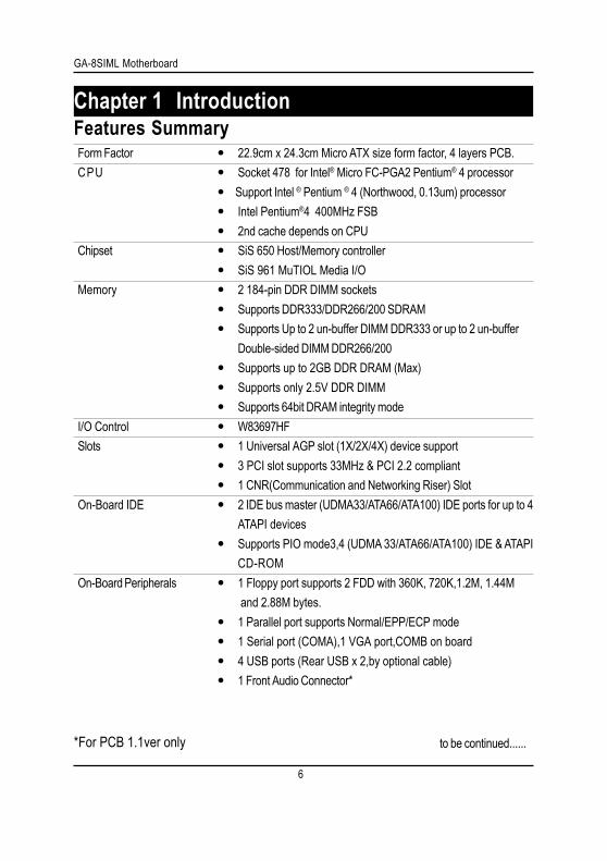
Chapter 1 Introduction
to be continued......
Features SummaryForm Factor 22.9cm x 24.3cm Micro ATX size form factor, 4 layers PCB.CPU Socket 478 for Intel® Micro FC-PGA2 Pentium® 4 processor
Support Intel ® Pentium ® 4 (Northwood, 0.13um) processorIntel Pentium®4 400MHz FSB2nd cache depends on CPU
Chipset SiS 650 Host/Memory controllerSiS 961 MuTIOL Media I/O
Memory 2 184-pin DDR DIMM socketsSupports DDR333/DDR266/200 SDRAMSupports Up to 2 un-buffer DIMM DDR333 or up to 2 un-bufferDouble-sided DIMM DDR266/200Supports up to 2GB DDR DRAM (Max)Supports only 2.5V DDR DIMMSupports 64bit DRAM integrity mode
I/O Control W83697HFSlots 1 Universal AGP slot (1X/2X/4X) device support
3 PCI slot supports 33MHz & PCI 2.2 compliant1 CNR(Communication and Networking Riser) Slot
On-Board IDE 2 IDE bus master (UDMA33/ATA66/ATA100) IDE ports for up to 4ATAPI devicesSupports PIO mode3,4 (UDMA 33/ATA66/ATA100) IDE & ATAPICD-ROM
On-Board Peripherals 1 Floppy port supports 2 FDD with 360K, 720K,1.2M, 1.44M and 2.88M bytes.1 Parallel port supports Normal/EPP/ECP mode1 Serial port (COMA),1 VGA port,COMB on board4 USB ports (Rear USB x 2,by optional cable)1 Front Audio Connector*
*For PCB 1.1ver only
7
Introduction
Please set the CPU host frequency in accordance with your processor’s specifications.We don’t recommend you to set the system bus frequency over the CPU’s specificationbecause these specific bus frequencies are not the standard specifications for CPU,chipset and most of the peripherals. Whether your system can run under these specificbus frequencies properly will depend on your hardware configurations, including CPU,Chipsets,SDRAM,Cards….etc.
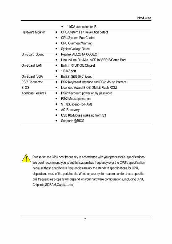
1 IrDA connector for IRHardware Monitor CPU/System Fan Revolution detect
CPU/System Fan ControlCPU Overheat WarningSystem Voltage Detect
On-Board Sound Realtek ALC201A CODECLine In/Line Out/Mic In/CD In/ SPDIF/Game Port
On-Board LAN Builit in RTL8100L Chipset1 RJ45 port
On-Board VGA Builit in SiS650 ChipsetPS/2 Connector PS/2 Keyboard interface and PS/2 Mouse interaceBIOS Licensed Award BIOS, 2M bit Flash ROMAdditional Features PS/2 Keyboard power on by password
PS/2 Mouse power onSTR(Suspend-To-RAM)AC RecoveryUSB KB/Mouse wake up from S3Supports @BIOS
8
GA-8SIML Motherboard
CI
DIMM_LED
SPDIF
F_AUDIO*
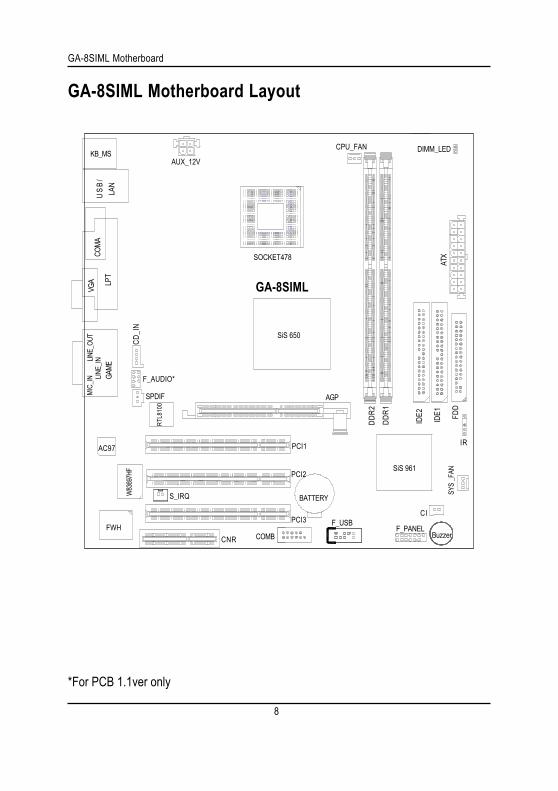
*For PCB 1.1ver only
GA-8SIML Motherboard Layout
GA-8SIML
KB_MS
COMA
COMB
LPT
GAME
LINE_
INLINE_
OUT
MIC_
INU
SB/
LAN
AUX_12V
CD_I
N
F_PANEL
BATTERY
SYS
_FAN
SiS 650
SOCKET478
CPU_FAN
ATX
FDD
IDE1
IDE2
AGP
PCI1
PCI2
PCI3 F_USB
DDR2
DDR1
W83
697H
F
FWH
IR
RTL8
100
AC97
CNR
SiS 961
VGA
S_IRQ
Buzzer
9
Hardware Installation Process
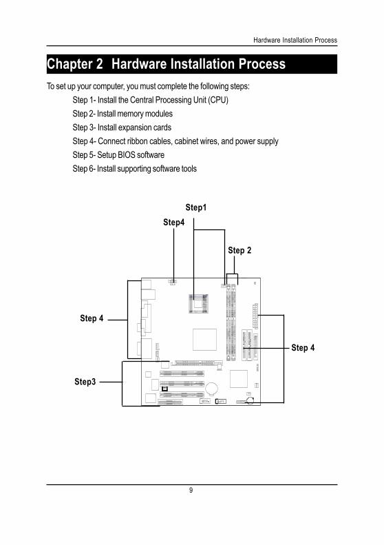
To set up your computer, you must complete the following steps:Step 1- Install the Central Processing Unit (CPU)Step 2- Install memory modulesStep 3- Install expansion cardsStep 4- Connect ribbon cables, cabinet wires, and power supplyStep 5- Setup BIOS softwareStep 6- Install supporting software tools
Chapter 2 Hardware Installation Process
Step 2
Step4
Step3
Step 4
Step 4
Step1

1 0
GA-8SIML Motherboard
Step 1: Install the Central Processing Unit (CPU)CPU Installation
Pin1 indicator Pin1 indicator
CPU Top View CPU Bottom View
Socket Actuation Lever
1. Pull up the CPU socket leverand up to 90-degree angle.
Pin1 indicator
2. Locate Pin 1 in the socket and lookfor a (golden) cut edge on the CPUupper corner. Then insert the CPUinto the socket.3. Press down the CPU socket
lever and finish CPU installation.
Please make sure the CPU type is supported by the motherboard.
If you do not match the CPU socket Pin 1 and CPU cut edge well, it will cause improper installation. Please change the insert orientation.
1 1
Hardware Installation Process
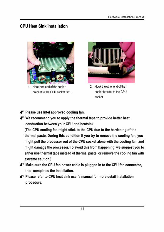
CPU Heat Sink Installation
1. Hook one end of the coolerbracket to the CPU socket first.
2. Hook the other end of thecooler bracket to the CPUsocket.
Please use Intel approved cooling fan.We recommend you to apply the thermal tape to provide better heatconduction between your CPU and heatsink.(The CPU cooling fan might stick to the CPU due to the hardening of thethermal paste. During this condition if you try to remove the cooling fan, youmight pull the processor out of the CPU socket alone with the cooling fan, andmight damage the processor. To avoid this from happening, we suggest you toeither use thermal tape instead of thermal paste, or remove the cooling fan withextreme caution.)Make sure the CPU fan power cable is plugged in to the CPU fan connector,this completes the installation.Please refer to CPU heat sink user’s manual for more detail installationprocedure.
1 2
GA-8SIML Motherboard
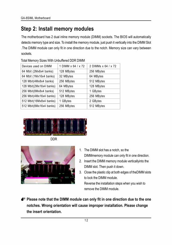
Please note that the DIMM module can only fit in one direction due to the onenotches. Wrong orientation will cause improper installation. Please changethe insert orientation.
DDR
1. The DIMM slot has a notch, so theDIMMmemory module can only fit in one direction.
2. Insert the DIMM memory module verticallyinto theDIMM slot. Then push it down.
3. Close the plastic clip at both edges of theDIMM slotsto lock the DIMM module.Reverse the installation steps when you wish toremove the DIMM module.
Step 2: Install memory modulesThe motherboard has 2 dual inline memory module (DIMM) sockets. The BIOS will automaticallydetects memory type and size. To install the memory module, just push it vertically into the DIMM Slot.The DIMM module can only fit in one direction due to the notch. Memory size can vary betweensockets.
Total Memory Sizes With Unbuffered DDR DIMM Devices used on DIMM 1 DIMM x 64 / x 72 2 DIMMs x 64 / x 72 64 Mbit (2Mx8x4 banks) 128 MBytes 256 MBytes 64 Mbit (1Mx16x4 banks) 32 MBytes 64 MBytes 128 Mbit(4Mx8x4 banks) 256 MBytes 512 MBytes 128 Mbit(2Mx16x4 banks) 64 MBytes 128 MBytes 256 Mbit(8Mx8x4 banks) 512 MBytes 1 GBytes 256 Mbit(4Mx16x4 banks) 128 MBytes 256 MBytes 512 Mbit(16Mx8x4 banks) 1 GBytes 2 GBytes 512 Mbit(8Mx16x4 banks) 256 MBytes 512 MBytes
1 3
Hardware Installation Process
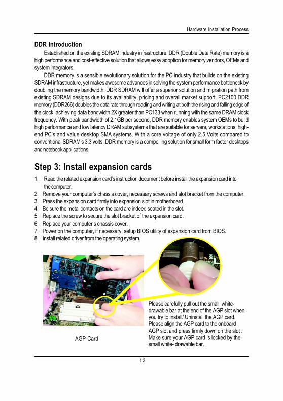
Step 3: Install expansion cards1. Read the related expansion card’s instruction document before install the expansion card into
the computer.2. Remove your computer’s chassis cover, necessary screws and slot bracket from the computer.3. Press the expansion card firmly into expansion slot in motherboard.4. Be sure the metal contacts on the card are indeed seated in the slot.5. Replace the screw to secure the slot bracket of the expansion card.6. Replace your computer’s chassis cover.7. Power on the computer, if necessary, setup BIOS utility of expansion card from BIOS.8. Install related driver from the operating system.
AGP Card
Please carefully pull out the small white-drawable bar at the end of the AGP slot whenyou try to install/ Uninstall the AGP card.Please align the AGP card to the onboardAGP slot and press firmly down on the slot .Make sure your AGP card is locked by thesmall white- drawable bar.
Established on the existing SDRAM industry infrastructure, DDR (Double Data Rate) memory is ahigh performance and cost-effective solution that allows easy adoption for memory vendors, OEMs andsystem integrators.
DDR memory is a sensible evolutionary solution for the PC industry that builds on the existingSDRAM infrastructure, yet makes awesome advances in solving the system performance bottleneck bydoubling the memory bandwidth. DDR SDRAM will offer a superior solution and migration path fromexisting SDRAM designs due to its availability, pricing and overall market support. PC2100 DDRmemory (DDR266) doubles the data rate through reading and writing at both the rising and falling edge ofthe clock, achieving data bandwidth 2X greater than PC133 when running with the same DRAM clockfrequency. With peak bandwidth of 2.1GB per second, DDR memory enables system OEMs to buildhigh performance and low latency DRAM subsystems that are suitable for servers, workstations, high-end PC's and value desktop SMA systems. With a core voltage of only 2.5 Volts compared toconventional SDRAM's 3.3 volts, DDR memory is a compelling solution for small form factor desktopsand notebook applications.
DDR Introduction
1 4
GA-8SIML Motherboard
Step 4: Connect ribbon cables, cabinet wires, and powersupply
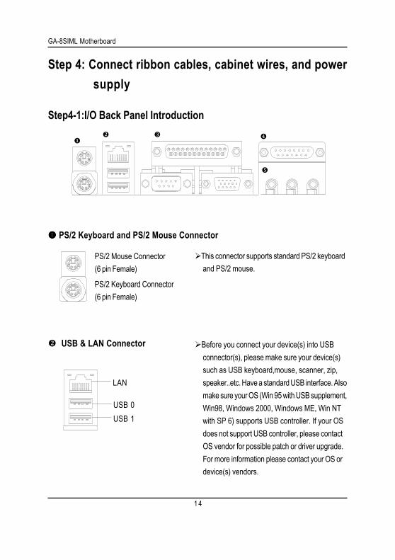
Step4-1:I/O Back Panel Introduction
PS/2 Keyboard and PS/2 Mouse Connector
This connector supports standard PS/2 keyboardand PS/2 mouse.
USB & LAN Connector Before you connect your device(s) into USBconnector(s), please make sure your device(s)such as USB keyboard,mouse, scanner, zip,speaker..etc. Have a standard USB interface. Alsomake sure your OS (Win 95 with USB supplement,Win98, Windows 2000, Windows ME, Win NTwith SP 6) supports USB controller. If your OSdoes not support USB controller, please contactOS vendor for possible patch or driver upgrade.For more information please contact your OS ordevice(s) vendors.
USB 0USB 1
LAN
PS/2 Mouse Connector(6 pin Female)
PS/2 Keyboard Connector(6 pin Female)
1 5
Hardware Installation Process
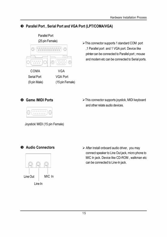
Game /MIDI Ports
Audio Connectors
This connector supports joystick, MIDI keyboardand other relate audio devices.
After install onboard audio driver, you mayconnect speaker to Line Out jack, micro phone toMIC In jack. Device like CD-ROM , walkman etccan be connected to Line-In jack.
Line In
MIC InLine Out
Parallel Port , Serial Port and VGA Port (LPT/COMA/VGA)
This connector supports 1 standard COM port,1 Parallel port and 1 VGA port. Device likeprintercan be connected to Parallel port ; mouseand modem etc can be connected to Serial ports.
Parallel Port(25 pin Female)
COMA VGASerial Port(9 pin Male)
VGA Port(15 pin Female)
Joystick/ MIDI (15 pin Female)
1 6
GA-8SIML Motherboard
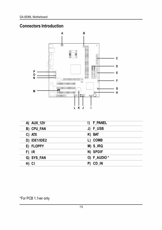
Connectors Introduction
A) AUX_12VB) CPU_FANC) ATXD) IDE1/IDE2E) FLOPPYF) IRG) SYS_FANH) CI
C
E
F
GH
A B
D
IJL
M
I ) F_PANELJ) F_USBK) BATL) COMBM) S_IRQN) SPDIFO) F_AUDIO *P) CD_IN
ON
K
P
*For PCB 1.1ver only
1 7
Hardware Installation Process
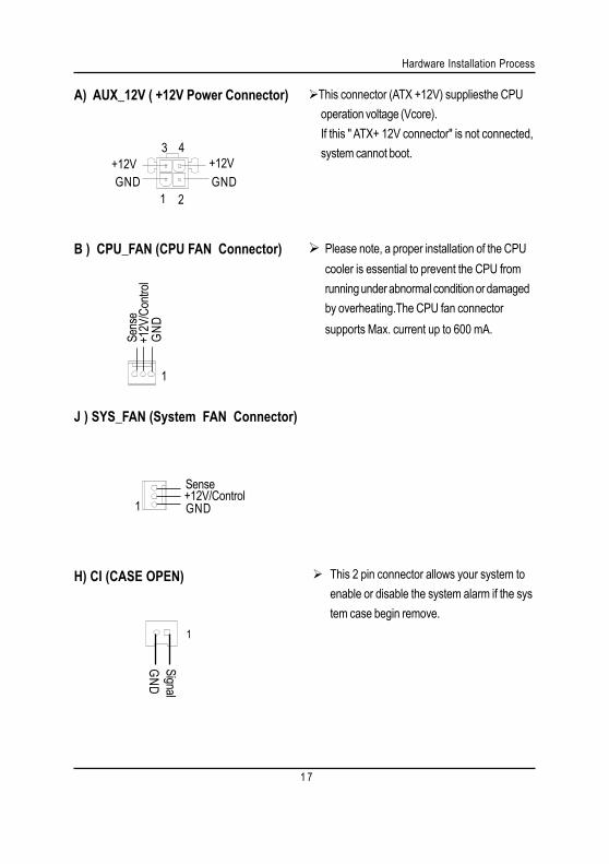
B ) CPU_FAN (CPU FAN Connector)
1
+12V
/Con
trol
Sens
e
GND
This connector (ATX +12V) suppliesthe CPUoperation voltage (Vcore).If this " ATX+ 12V connector" is not connected,system cannot boot.
A) AUX_12V ( +12V Power Connector)
Please note, a proper installation of the CPUcooler is essential to prevent the CPU fromrunning under abnormal condition or damagedby overheating.The CPU fan connectorsupports Max. current up to 600 mA.
J ) SYS_FAN (System FAN Connector)
4+12V
GND+12V
GND
3
21
1+12V/ControlSense
GND
H) CI (CASE OPEN) This 2 pin connector allows your system toenable or disable the system alarm if the system case begin remove.
1
SignalGND
1 8
GA-8SIML Motherboard
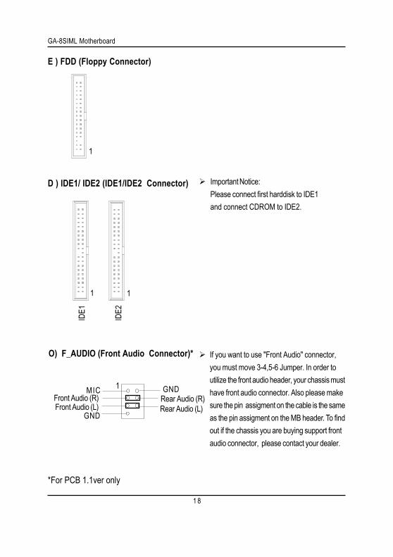
E ) FDD (Floppy Connector)
IDE1
1
IDE2
1
1
D ) IDE1/ IDE2 (IDE1/IDE2 Connector) Important Notice:Please connect first harddisk to IDE1and connect CDROM to IDE2.
O) F_AUDIO (Front Audio Connector)* If you want to use "Front Audio" connector,you must move 3-4,5-6 Jumper. In order toutilize the front audio header, your chassis musthave front audio connector. Also please makesure the pin assigment on the cable is the sameas the pin assigment on the MB header. To findout if the chassis you are buying support frontaudio connector, please contact your dealer.
Front Audio (L)
1 GND
GND
MICRear Audio (R)Rear Audio (L)
Front Audio (R)
*For PCB 1.1ver only

1 9
Hardware Installation Process
P) CD_IN (CD Audio Line In)
1 CD-L
CD-RGND
N)SPDIF
VCCSPDIF OutGND
1
The SPDIF output is capable of providingdigital audio to external speakers or compressed AC3 data to an external DolbyDigital Decoder. Use this feature only whenyour stereo system has digital outputfunction.
1
L) COM B
M) S_IRQ(For special design, for example: PCMCIA add on card)
1
Signa
lGN
D
2 0
GA-8SIML Motherboard
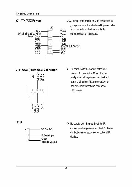
C ) ATX (ATX Power)
PS-ON(Soft On/Off)
3.3V3.3VGNDGNDGND
VCCVCC
+12V5V SB (Stand by +5V)
Power Good
3.3VGNDGND
GNDGND
VCCVCC
-12V
1
20
-5V
AC power cord should only be connected toyour power supply unit after ATX power cableand other related devices are firmlyconnected to the mainboard.
Be careful with the polarity of the IRconnectorwhile you connect the IR. Pleasecontact you nearest dealer for optional IRdevice.
F)IR
VCC(+5V)
IR Data InputGNDIR Data Output
1
Be careful with the polarity of the frontpanel USB connector. Check the pinassignment while you connect the frontpanel USB cable. Please contact yournearest dealer for optional front panelUSB cable.
GND
USB
3+
Powe
rUS
B 2-
USB
2+
1
GND
USB
3-Po
wer
J) F_USB (Front USB Connector)
2 1
Hardware Installation Process
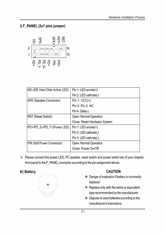
I) F_PANEL (2x7 pins jumper)
Please connect the power LED, PC speaker, reset switch and power switch etc of your chassisfront panel to the F_PANEL connector according to the pin assignment above.
HD (IDE Hard Disk Active LED) Pin 1: LED anode(+)Pin 2: LED cathode(-)
SPK (Speaker Connector) Pin 1: VCC(+)Pin 2- Pin 3: NCPin 4: Data(-)
RST (Reset Switch) Open: Normal OperationClose: Reset Hardware System
PD+/PD_G-/PD_Y-(Power LED) Pin 1: LED anode(+)Pin 2: LED cathode(-)Pin 3: LED cathode(-)
PW (Soft Power Connector) Open: Normal OperationClose: Power On/Off
HD+PD_Y-
2 14
1 13
PD+PW
-PW
+RST-
SPK+
SPK-1
1RST+
HD-
PD_G-
K) Battery
+
CAUTIONDanger of explosion if battery is incorrectlyreplaced.Replace only with the same or equivalenttype recommended by the manufacturer.Dispose of used batteries according to themanufacturer’s instructions.
GA-8SIML Motherboard
2 2
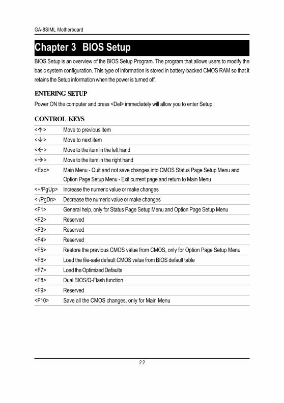
< > Move to previous item< > Move to next item< > Move to the item in the left hand< > Move to the item in the right hand<Esc> Main Menu - Quit and not save changes into CMOS Status Page Setup Menu and
Option Page Setup Menu - Exit current page and return to Main Menu<+/PgUp> Increase the numeric value or make changes<-/PgDn> Decrease the numeric value or make changes<F1> General help, only for Status Page Setup Menu and Option Page Setup Menu<F2> Reserved<F3> Reserved<F4> Reserved<F5> Restore the previous CMOS value from CMOS, only for Option Page Setup Menu<F6> Load the file-safe default CMOS value from BIOS default table<F7> Load the Optimized Defaults<F8> Dual BIOS/Q-Flash function<F9> Reserved<F10> Save all the CMOS changes, only for Main Menu
BIOS Setup is an overview of the BIOS Setup Program. The program that allows users to modify thebasic system configuration. This type of information is stored in battery-backed CMOS RAM so that itretains the Setup information when the power is turned off.
Chapter 3 BIOS Setup
ENTERINGPower ON the computer and press <Del> immediately will allow you to enter Setup.
CONTROL
SETUP
KEYS
BIOS Setup
2 3
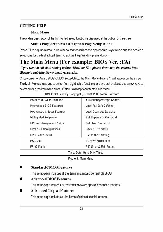
Standard CMOS FeaturesThis setup page includes all the items in standard compatible BIOS.Advanced BIOS FeaturesThis setup page includes all the items of Award special enhanced features.Advanced Chipset FeaturesThis setup page includes all the items of chipset special features.
Main MenuThe on-line description of the highlighted setup function is displayed at the bottom of the screen.
Status Page Setup Menu / Option Page Setup MenuPress F1 to pop up a small help window that describes the appropriate keys to use and the possibleselections for the highlighted item. To exit the Help Window press <Esc>.
The Main Menu (For example: BIOS Ver. :FA) If you want detail data setting before “BIOS ver FA“, please download the manual fromGigabyte web http://www.gigabyte.com.tw.Once you enter Award BIOS CMOS Setup Utility, the Main Menu (Figure 1) will appear on the screen.The Main Menu allows you to select from eight setup functions and two exit choices. Use arrow keys toselect among the items and press <Enter> to accept or enter the sub-menu.
CMOS Setup Utility-Copyright (C) 1984-2002 Award Software
Standard CMOS Features Frequency/Voltage Control
Advanced BIOS Features Load Fail-Safe Defaults
Advanced Chipset Features Load Optimized Defaults
Integrated Peripherals Set Supervisor Password
Power Management Setup Set User Password
PnP/PCI Configurations Save & Exit Setup
PC Health Status Exit Without Saving
ESC:Quit :Select Item
F8: Q-Flash F10:Save & Exit Setup
Time, Date, Hard Disk Type...
Figure 1: Main Menu
GETTING HELP
GA-8SIML Motherboard
2 4
Integrated PeripheralsThis setup page includes all onboard peripherals.Power Management SetupThis setup page includes all the items of Green function features.PnP/PCI ConfigurationsThis setup page includes all the configurations of PCI & PnP ISA resources.PC Health StatusThis setup page is the System auto detect Temperature, voltage, fan, speed.Frequency/Voltage ControlThis setup page is control CPU’s clock and frequency ratio.Load Fail-Safe DefaultsFail-Safe Defaults indicates the value of the system parameters which the system wouldbe in safe configuration.Load Optimized DefaultsOptimized Defaults indicates the value of the system parameters which the system wouldbe in best performance configuration.Set Supervisor passwordChange, set, or disable password. It allows you to limit access to the system and Setup,or just to Setup.Set User passwordChange, set, or disable password. It allows you to limit access to the system.Save & Exit SetupSave CMOS value settings to CMOS and exit setup.Exit Without SavingAbandon all CMOS value changes and exit setup.
BIOS Setup
2 5
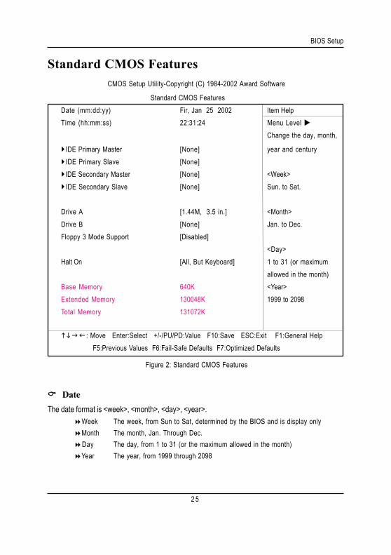
Standard CMOS Features CMOS Setup Utility-Copyright (C) 1984-2002 Award Software
Standard CMOS FeaturesDate (mm:dd:yy) Fir, Jan 25 2002 Item HelpTime (hh:mm:ss) 22:31:24 Menu Level
Change the day, month,
IDE Primary Master [None] year and centuryIDE Primary Slave [None]IDE Secondary Master [None] <Week>IDE Secondary Slave [None] Sun. to Sat.
Drive A [1.44M, 3.5 in.] <Month>Drive B [None] Jan. to Dec.Floppy 3 Mode Support [Disabled]
<Day>Halt On [All, But Keyboard] 1 to 31 (or maximum
allowed in the month)Base Memory 640K <Year>Extended Memory 130048K 1999 to 2098Total Memory 131072K
: Move Enter:Select +/-/PU/PD:Value F10:Save ESC:Exit F1:General HelpF5:Previous Values F6:Fail-Safe Defaults F7:Optimized Defaults
Figure 2: Standard CMOS Features
DateThe date format is <week>, <month>, <day>, <year>.
Week The week, from Sun to Sat, determined by the BIOS and is display onlyMonth The month, Jan. Through Dec.Day The day, from 1 to 31 (or the maximum allowed in the month)Year The year, from 1999 through 2098

GA-8SIML Motherboard
2 6
TimeThe times format in <hour> <minute> <second>. The time is calculated base on the 24-hour military-
time clock. For example, 1 p.m. is 13:00:00.
IDE Primary Master, Slave / IDE Secondary Master, SlaveThe category identifies the types of hard disk from drive C to F that has been installed in the computer.
There are two types: auto type, and manual type. Manual type is user-definable; Auto type which willautomatically detect HDD type.Note that the specifications of your drive must match with the drive table. The hard disk will not workproperly if you enter improper information for this category.If you select User Type, related information will be asked to enter to the following items. Enter theinformation directly from the keyboard and press <Enter>. Such information should be provided in thedocumentation form your hard disk vendor or the system manufacturer.
CYLS. Number of cylinders
HEADS Number of heads
PRECOMP Write precomp
LANDZONE Landing zone
SECTORSNumber of sectors
If a hard disk has not been installed select NONE and press <Enter>.
Drive A / Drive BThe category identifies the types of floppy disk drive A or drive B that has been installed in thecomputer.
None No floppy drive installed
360K, 5.25 in. 5.25 inch PC-type standard drive; 360K byte capacity.
1.2M, 5.25 in. 5.25 inch AT-type high-density drive; 1.2M byte capacity
(3.5 inch when 3 Mode is Enabled).
720K, 3.5 in. 3.5 inch double-sided drive; 720K byte capacity
1.44M, 3.5 in. 3.5 inch double-sided drive; 1.44M byte capacity.
2.88M, 3.5 in. 3.5 inch double-sided drive; 2.88M byte capacity.
BIOS Setup
2 7
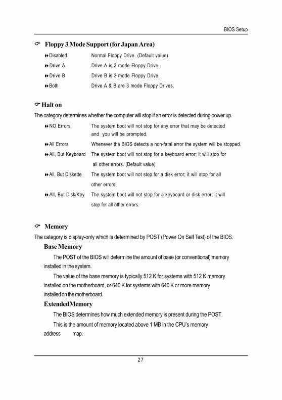
Floppy 3 Mode Support (for Japan Area)Disabled Normal Floppy Drive. (Default value)
Drive A Drive A is 3 mode Floppy Drive.
Drive B Drive B is 3 mode Floppy Drive.
Both Drive A & B are 3 mode Floppy Drives.
Halt onThe category determines whether the computer will stop if an error is detected during power up.
NO Errors The system boot will not stop for any error that may be detectedand you will be prompted.
All Errors Whenever the BIOS detects a non-fatal error the system will be stopped.
All, But Keyboard The system boot will not stop for a keyboard error; it will stop for
all other errors. (Default value)
All, But Diskette The system boot will not stop for a disk error; it will stop for all
other errors.
All, But Disk/Key The system boot will not stop for a keyboard or disk error; it will
stop for all other errors.
MemoryThe category is display-only which is determined by POST (Power On Self Test) of the BIOS.
Base MemoryThe POST of the BIOS will determine the amount of base (or conventional) memory
installed in the system.The value of the base memory is typically 512 K for systems with 512 K memory
installed on the motherboard, or 640 K for systems with 640 K or more memoryinstalled on the motherboard.Extended Memory
The BIOS determines how much extended memory is present during the POST.This is the amount of memory located above 1 MB in the CPU’s memory
address map.
GA-8SIML Motherboard
2 8
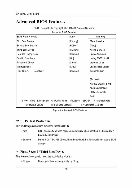
Advanced BIOS Features
BIOS Flash ProtectionThis field lets you determine the states that flash BIOS
Auto BIOS enables flash write access automatically when updating BIOS data/DMI/ESCD. (Default Value)
Enabled During POST, DMI/ESCD would not be updated. But flash tools can update BIOSalways.
First / Second / Third Boot DeviceThis feature allows you to select the boot device priority.
Floppy Select your boot device priority by Floppy.
CMOS Setup Utility-Copyright (C) 1984-2002 Award SoftwareAdvanced BIOS Features
BIOS Flash Protection [Auto] Item Help
First Boot Device [Floppy] Menu Level Second Boot Device [HDD-0] [Auto]Third Boot Device [CDROM] Allows BIOS toBoot Up Floppy Seek [Disabled] update flash dataBootUp Num-Lock [On] during POST. It stillPassword Check [Setup] prevents otherInterrupt Mode [APIC] unauthorized utilitiesHDD S.M.A.R.T. Capability [Disabled] to update flash
[Enabled]Always prevent BIOSand unauthorizedutilities to updateflash
: Move Enter:Select +/-/PU/PD:Value F10:Save ESC:Exit F1:General Help F5:Previous Values F6:Fail-Safe Defaults F7:Optimized Defaults
Figure 3: Advanced BIOS Features
BIOS Setup
2 9
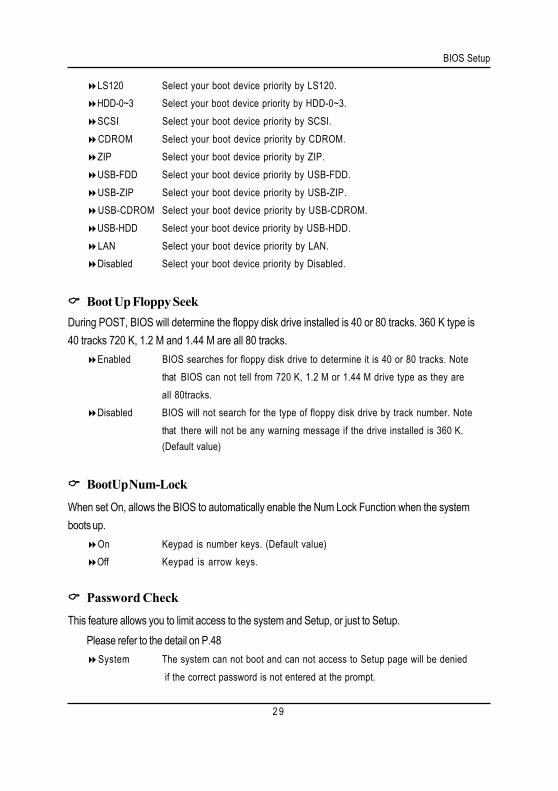
LS120 Select your boot device priority by LS120.HDD-0~3 Select your boot device priority by HDD-0~3.SCSI Select your boot device priority by SCSI.CDROM Select your boot device priority by CDROM.ZIP Select your boot device priority by ZIP.USB-FDD Select your boot device priority by USB-FDD.USB-ZIP Select your boot device priority by USB-ZIP.USB-CDROM Select your boot device priority by USB-CDROM.USB-HDD Select your boot device priority by USB-HDD.LAN Select your boot device priority by LAN.Disabled Select your boot device priority by Disabled.
Boot Up Floppy SeekDuring POST, BIOS will determine the floppy disk drive installed is 40 or 80 tracks. 360 K type is40 tracks 720 K, 1.2 M and 1.44 M are all 80 tracks.
Enabled BIOS searches for floppy disk drive to determine it is 40 or 80 tracks. Notethat BIOS can not tell from 720 K, 1.2 M or 1.44 M drive type as they areall 80tracks.
Disabled BIOS will not search for the type of floppy disk drive by track number. Notethat there will not be any warning message if the drive installed is 360 K.(Default value)
BootUp Num-Lock
When set On, allows the BIOS to automatically enable the Num Lock Function when the systemboots up.
On Keypad is number keys. (Default value)Off Keypad is arrow keys.
Password Check
This feature allows you to limit access to the system and Setup, or just to Setup.Please refer to the detail on P.48
System The system can not boot and can not access to Setup page will be denied if the correct password is not entered at the prompt.

GA-8SIML Motherboard
3 0
Setup The system will boot, but access to Setup will be denied if the correctpassword is not entered at the prompt. (Default value)
Interrupt ModeAPIC Through IOAPIC generate more IRQ for system use.(Default value)PIC Use AT stantard IRQ controlles to generate IRQ.
When you already have IOAPIC enable system and want to upgrade the system please note, sincerunning an IOAPIC enabled OS (like Windows NT,Windows 2000, Windows XP...) system with noneIOAPIC HW support will cause the system to hang. Following are some situations users might run into:1.An IOAPIC enabled OS and change the BIOS setting from IOAPIC to PIC, this will cause your systemto hang.)
HDD S.M.A.R.T Capability
S.M.A.R.T. stands for Self-Monitoring and Analysis Reporting Technology which allows your harddisk drive to report any read/write errors and issue a warning with LDCM installed.
Enabled Enable HDD S.M.A.R.T. Capability.Disabled Disable HDD S.M.A.R.T. Capability. (Default value)
BIOS Setup
3 1
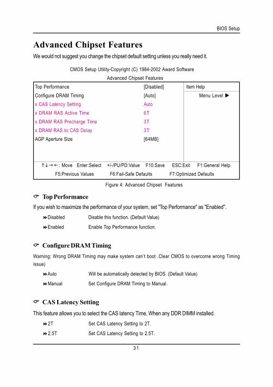
Advanced Chipset Features
Figure 4: Advanced Chipset Features
CMOS Setup Utility-Copyright (C) 1984-2002 Award SoftwareAdvanced Chipset Features
Top Performance [Disabled] Item HelpConfigure DRAM Timing [Auto] Menu Level x CAS Latency Setting Autox DRAM RAS Active Time 6Tx DRAM RAS Precharge Time 3Tx DRAM RAS to CAS Delay 3TAGP Aperture Size [64MB]
: Move Enter:Select +/-/PU/PD:Value F10:Save ESC:Exit F1:General Help F5:Previous Values F6:Fail-Safe Defaults F7:Optimized Defaults
We would not suggest you change the chipset default setting unless you really need it.
Top PerformanceIf you wish to maximize the performance of your system, set "Top Performance" as "Enabled".
Disabled Disable this function. (Default Value)
Enabled Enable Top Performance function.
Configure DRAM TimingWarning: Wrong DRAM Timing may make system can’t boot .Clear CMOS to overcome wrong Timingissue)
Auto Will be automatically detected by BIOS. (Default Value)
Manual Set Configure DRAM Timing to Manual.
CAS Latency Setting
This feature allows you to select the CAS latency Time, When any DDR DIMM installed.2T Set CAS Latency Setting to 2T.
2.5T Set CAS Latency Setting to 2.5T.
GA-8SIML Motherboard
3 2
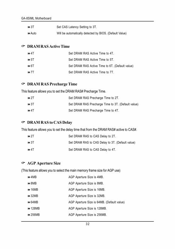
3T Set CAS Latency Setting to 3T.
Auto Will be automatically detected by BIOS. (Default Value)
DRAM RAS Active Time4T Set DRAM RAS Active Time to 4T.
5T Set DRAM RAS Active Time to 5T.
6T Set DRAM RAS Active Time to 6T. (Default value)
7T Set DRAM RAS Active Time to 7T.
DRAM RAS Precharge Time
This feature allows you to set the DRAM RAS# Precharge Time.2T Set DRAM RAS Precharge Time to 2T.
3T Set DRAM RAS Precharge Time to 3T. (Default value)
4T Set DRAM RAS Precharge Time to 4T.
DRAM RAS to CAS Delay
This feature allows you to set the delay time that from the DRAM RAS# active to CAS#.2T Set DRAM RAS to CAS Delay to 2T.
3T Set DRAM RAS to CAS Delay to 3T. (Default value)
4T Set DRAM RAS to CAS Delay to 4T.
AGP Aperture Size
(This feature allows you to select the main memory frame size for AGP use)4MB AGP Aperture Size is 4MB.
8MB AGP Aperture Size is 8MB.
16MB AGP Aperture Size is 16MB.
32MB AGP Aperture Size is 32MB.
64MB AGP Aperture Size is 64MB. (Default value)
128MB AGP Aperture Size is 128MB.
256MB AGP Aperture Size is 256MB.
BIOS Setup
3 3
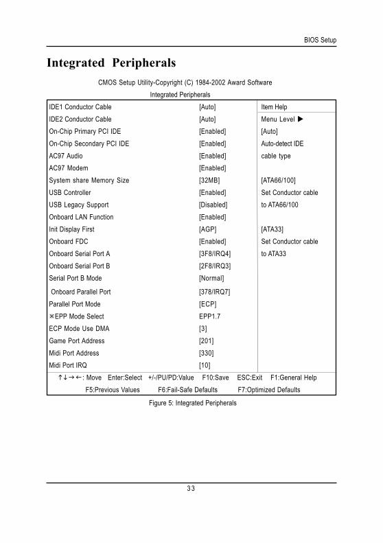
Integrated Peripherals
Figure 5: Integrated Peripherals
CMOS Setup Utility-Copyright (C) 1984-2002 Award SoftwareIntegrated Peripherals
IDE1 Conductor Cable [Auto] Item HelpIDE2 Conductor Cable [Auto] Menu Level On-Chip Primary PCI IDE [Enabled] [Auto]On-Chip Secondary PCI IDE [Enabled] Auto-detect IDEAC97 Audio [Enabled] cable typeAC97 Modem [Enabled]System share Memory Size [32MB] [ATA66/100]USB Controller [Enabled] Set Conductor cableUSB Legacy Support [Disabled] to ATA66/100Onboard LAN Function [Enabled]Init Display First [AGP] [ATA33]Onboard FDC [Enabled] Set Conductor cableOnboard Serial Port A [3F8/IRQ4] to ATA33Onboard Serial Port B [2F8/IRQ3]Serial Port B Mode [Normal]
Onboard Parallel Port [378/IRQ7]Parallel Port Mode [ECP]
EPP Mode Select EPP1.7ECP Mode Use DMA [3]Game Port Address [201]Midi Port Address [330]Midi Port IRQ [10] : Move Enter:Select +/-/PU/PD:Value F10:Save ESC:Exit F1:General Help F5:Previous Values F6:Fail-Safe Defaults F7:Optimized Defaults
GA-8SIML Motherboard
3 4
IDE1 Conductor CableAuto Will be automatically detected by BIOS. (Default Value)
ATA66/100 Set IDE1 Conductor Cable to ATA66/100 (Please make sure your IDE deviceand cable is compatible with ATA66/100).
ATA33 Set IDE1 Conductor Cable to ATA33 (Please make sure your IDE device andcable is compatible with ATA33).
IDE2 Conductor CableAuto Will be automatically detected by BIOS. (Default Value)
ATA66/100 Set IDE2 Conductor Cable to ATA66/100 (Please make sure your IDE deviceand cable is compatible with ATA66/100).
ATA33 Set IDE2 Conductor Cable to ATA33 (Please make sure your IDE device andcable is compatible with ATA33).
On-Chip Primary PCI IDE
When enabled, allows you to use the onboard primary PCI IDE.Enabled Enable onboard 1st channel IDE port. (Default value)
Disabled Disable onboard 1st channel IDE port.
On-Chip Secondary PCI IDE
When enabled, allows you to use the onboard secondary PCI IDE.Enabled Enable onboard 2nd channel IDE port. (Default value)
Disabled Disable onboard 2nd channel IDE port.
AC97 AudioEnabled Enable onboard AC'97 audio function. (Default Value)
Disabled Disable this function.
AC97 ModemEnabled BIOS will search MC97 Codec (AMR Modem Card). If found, MC97 function
will be enabled. If no MC97 Codec found, MC97 function will be disabled.
BIOS Setup
3 5
(Default Value)
Disabled Disable this function.
Share Memory Size4MB/8MB/16MB/32MB/64MB Set onchip VGA shared memory size.(Default Value:32MB)
USB Controller
Disable this option if you are not using the onboard USB feature.Enabled Enable USB Controller. (Default value)
Disabled Disable USB Controller.
USB Legacy SupportEnabled Enable USB Legacy Support.Disabled Disable this function.(Default Value)
Onboard LanDisabled Disable this function.Enabled Enable Onboard Lan Chip function. (Default Value)
Init Display First
This feature allows you to select the first initation of the monitor display from which card, when youinstall an AGP VGA card and a PCI VGA card on board.
PCI Set Init Display First to PCI Slot.
AGP Set Init Display First to AGP. (Default value)
OnBoard FDC
When enabled, the fioppy diskette drive (FDD) controller is activated.Disabled Disable this function.Enabled Enable on board floppy disk controller.(Default value)
Onboard Serial Port AAuto BIOS will automatically setup the port A address.3F8/IRQ4 Enable onboard Serial port A and using daddress 3F8 , IRQ4. (Default Value)
GA-8SIML Motherboard
3 6
2F8/IRQ3 Enable onboard Serial port A and using daddress 2F8 , IRQ3.3E8/IRQ4 Enable onboard Serial port A and using daddress 3E8 , IRQ4.2E8/IRQ3 Enable onboard Serial port A and using daddress 2E8 , IRQ3.Disabled Disable onboard Serial port A.
Onboard Serial Port BAuto BIOS will automatically setup the port B address.3F8/IRQ4 Enable onboard Serial port B and using daddress 3F8 , IRQ4.2F8/IRQ3 Enable onboard Serial port B and using daddress 2F8 , IRQ3. (Default Value)3E8/IRQ4 Enable onboard Serial port B and using daddress 3E8 , IRQ4.2E8/IRQ3 Enable onboard Serial port B and using daddress 2E8 , IRQ3.Disabled Disable onboard Serial port B.
Serial Port B Mode (This item allows you to select the IR modes if the serial port B is used as an IR port.Set at Normal , ifyou use COM2 as the serial port as the serial port, instead as an IR port.)
ASKIR Set onboard I/O chip UART to ASKIR Mode.IrDA Set onboard I/O chip UART to IrDa Mode.Normal Set onboard I/O chip UART to Normal Mode. (Default Value)
OnBoard Parallel port
This feature allows you to select from a given set of parameters if the parallel port uses the onboard I/O controller.
378/IRQ7 Enable On Board LPT port and using address 378, IRQ7.(Default Value)
278/IRQ5 Enable On Board LPT port and using address 278, IRQ5.
3BC/IRQ7 Enable On Board LPT port and using address 3BC, IRQ7.Disabled Disable onboard Parallel port.
Parallel Port Mode
This feature allows you to connect with an advanced print via the port mode it supports.SPP Using Parallel port as Standard Parallel Port.EPP Using Parallel port as Enhanced Parallel Port.ECP Using Parallel port as Extended Capabilities Port.(Default Value)ECP+EPP Using Parallel port as ECP & EPP mode.
BIOS Setup
3 7
EPP Version
This feature allows you to select the EPP type version.EPP 1.9 Compliant with EPP 1.9 version.EPP 1.7 Compliant with EPP 1.7 version.(Default Value)
Parallel Port DMA
This feature allows you to select Direct Memory Access(DMA) channel if the ECP mode selected.3 Set Parallel Port DMA to 3.(Default Value)1 Set Parallel Port DMA to 1.
OnBoard Game Port
This feature allows you to select the game port address or disable it.Disabled Disable OnBoard Game Port.201h Set OnBoard Game Port to 201h. (Default Value)209h Set OnBoard Game Port to 209h.
OnBoard Midi Port
This feature allows you to select the Midi port address or disable it.Disabled Disable onboard Midi Port.300h Set onboard Midi Port to 300h.330h Set onboard Midi Port to 330h. (Default Value)290h Set onboard Midi Port to 290h.
Midi IRQ Select
This feature allows you to select Midi IRQ is enabled.IRQ 5 / 10 (Default Value:10)
GA-8SIML Motherboard
3 8
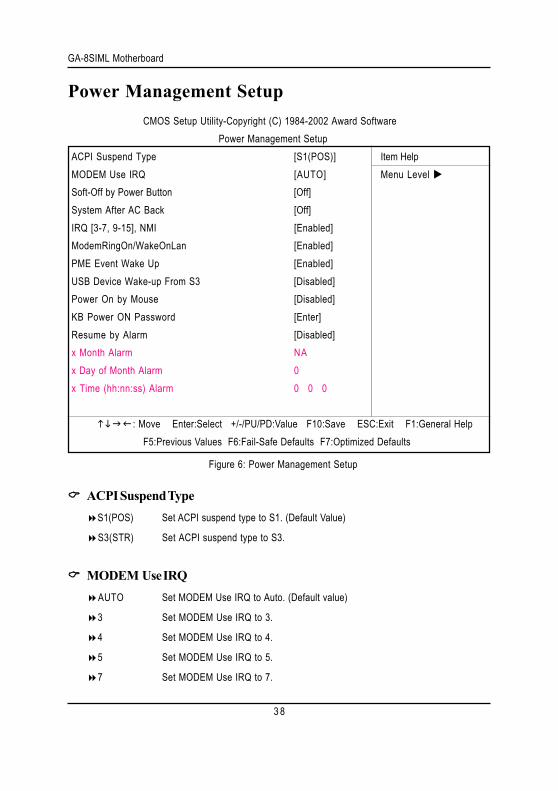
Power Management SetupCMOS Setup Utility-Copyright (C) 1984-2002 Award Software
Power Management SetupACPI Suspend Type [S1(POS)] Item HelpMODEM Use IRQ [AUTO] Menu Level Soft-Off by Power Button [Off]System After AC Back [Off]IRQ [3-7, 9-15], NMI [Enabled]ModemRingOn/WakeOnLan [Enabled]PME Event Wake Up [Enabled]USB Device Wake-up From S3 [Disabled]Power On by Mouse [Disabled]KB Power ON Password [Enter]Resume by Alarm [Disabled]x Month Alarm NAx Day of Month Alarm 0x Time (hh:nn:ss) Alarm 0 0 0
: Move Enter:Select +/-/PU/PD:Value F10:Save ESC:Exit F1:General HelpF5:Previous Values F6:Fail-Safe Defaults F7:Optimized Defaults
Figure 6: Power Management Setup
ACPI Suspend TypeS1(POS) Set ACPI suspend type to S1. (Default Value)
S3(STR) Set ACPI suspend type to S3.
MODEM Use IRQAUTO Set MODEM Use IRQ to Auto. (Default value)
3 Set MODEM Use IRQ to 3.
4 Set MODEM Use IRQ to 4.
5 Set MODEM Use IRQ to 5.
7 Set MODEM Use IRQ to 7.
BIOS Setup
3 9
9 Set MODEM Use IRQ to 9.
10 Set MODEM Use IRQ to 10.
11 Set MODEM Use IRQ to 11.
Soft-off by Power ButtonOff The user press the power button once, he can turn off the system.
(Default Value)
Suspend The user press the power button once, then he can enter suspend mode.
System after AC BackLast State When AC-power back to the system, the system will return to the Last state
before AC-power off.
Off When AC-power back to the system, the system will be in "Off" state.
(Default Value)
On When AC-power back to the system, the system will be in "On" state.
IRQ [3-7, 9-15], NMIDisabled Disable this function.
Enabled Enable this function. (Default value)
ModemRingOn/WakeOnLAN
An incoming call via modem awakes the system from its soft-off mode./When set at Enabled, an inputsignal comes from the other client/server on the LAN awarks the system from a soft off state ifconnected over LAN.
Disabled Disable Modem Ring on/wake on Lan function.
Enabled Enable Modem Ring on/wake on Lan. (Default Value)
PME Event Wake UP
When set at Enabled, any PCI-PM event awarkes the system from a PCI-PM controlled stateDisabled Disable this function.
GA-8SIML Motherboard
4 0
Enabled Enable PME Event Wake up. (Default Value)
USB Device Wake-up From S3
When set at Enabled, it allows USB Device to activate the system from ACPI S3 power savingmode.
Enabled Enable USB Device Wakeup.
Disabled Disable USB Device Wakeup. (Default Value)
Power On by MouseEnabled Enable PS2 Mouse Power Up Control function. (Default Value)
Disabled Disable this function.
KB Power ON PasswordEnter Input password (from 1 to 8 characters) and press Enter to set the Keyboard
Power On Password.
Resume by AlarmYou can set "Resume by Alarm" item to enabled and key in Data/time to power on system.
Disabled Disable this function. (Default Value)
Enabled Enable alarm function to POWER ON system.
If RTC Alarm Lead To Power On is Enabled.
Month Alarm : NA, 1~31
Day of Month Alarm : 1~31
Time ( hh: mm: ss) Alarm : (0~23) : (0~59) : (0~59)
BIOS Setup
4 1
PnP/PCI Configurations
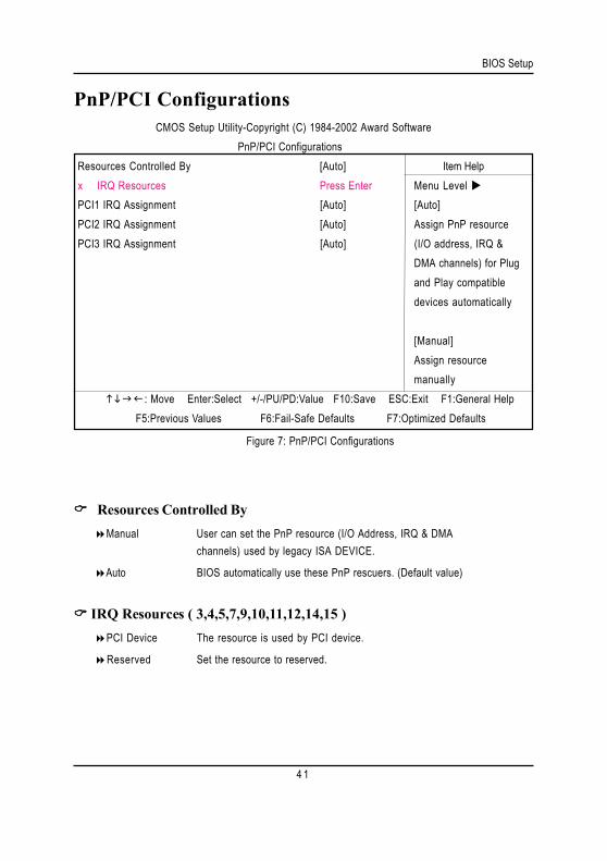
Figure 7: PnP/PCI Configurations
Resources Controlled ByManual User can set the PnP resource (I/O Address, IRQ & DMA
channels) used by legacy ISA DEVICE.
Auto BIOS automatically use these PnP rescuers. (Default value)
IRQ Resources ( 3,4,5,7,9,10,11,12,14,15 )PCI Device The resource is used by PCI device.
Reserved Set the resource to reserved.
CMOS Setup Utility-Copyright (C) 1984-2002 Award SoftwarePnP/PCI Configurations
Resources Controlled By [Auto] Item Helpx IRQ Resources Press Enter Menu Level PCI1 IRQ Assignment [Auto] [Auto]PCI2 IRQ Assignment [Auto] Assign PnP resourcePCI3 IRQ Assignment [Auto] (I/O address, IRQ &
DMA channels) for Plugand Play compatibledevices automatically
[Manual]Assign resourcemanually
: Move Enter:Select +/-/PU/PD:Value F10:Save ESC:Exit F1:General Help F5:Previous Values F6:Fail-Safe Defaults F7:Optimized Defaults
GA-8SIML Motherboard
4 2
PCI1 IRQ AssignmentAuto Auto assign IRQ to PCI1. (Default value)
3,4,5,7,9,10,11,12,14,15 Set IRQ 3,4,5,7,9,10,11,12,14,15 to PCI4.
PCI2 IRQ AssignmentAuto Auto assign IRQ to PCI2. (Default value)3,4,5,7,9,10,11,12,14,15 Set IRQ 3,4,5,7,9,10,11,12,14,15 to PCI1/5.
PCI3 IRQ AssignmentAuto Auto assign IRQ to PCI3. (Default value)
3,4,5,7,9,10,11,12,14,15 Set IRQ 3,4,5,7,9,10,11,12,14,15 to PCI2/6.
BIOS Setup
4 3
PC Health Status
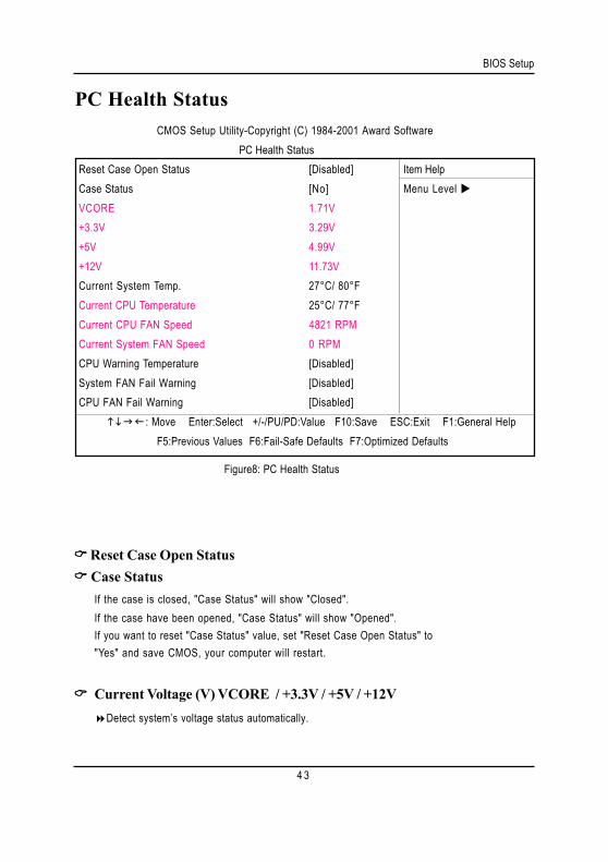
Figure8: PC Health Status
Reset Case Open Status Case Status
If the case is closed, "Case Status" will show "Closed".If the case have been opened, "Case Status" will show "Opened".If you want to reset "Case Status" value, set "Reset Case Open Status" to"Yes" and save CMOS, your computer will restart.
Current Voltage (V) VCORE / +3.3V / +5V / +12VDetect system’s voltage status automatically.
CMOS Setup Utility-Copyright (C) 1984-2001 Award SoftwarePC Health Status
Reset Case Open Status [Disabled] Item HelpCase Status [No] Menu Level VCORE 1.71V+3.3V 3.29V+5V 4.99V+12V 11.73VCurrent System Temp. 27°C/ 80°FCurrent CPU Temperature 25°C/ 77°FCurrent CPU FAN Speed 4821 RPMCurrent System FAN Speed 0 RPMCPU Warning Temperature [Disabled]System FAN Fail Warning [Disabled]CPU FAN Fail Warning [Disabled] : Move Enter:Select +/-/PU/PD:Value F10:Save ESC:Exit F1:General Help
F5:Previous Values F6:Fail-Safe Defaults F7:Optimized Defaults
GA-8SIML Motherboard
4 4
Current System TemperatureDetect System Temp. automatically.
Current CPU TemperatureDetect CPU Temp. automatically.
Current CPU Fan / System Fan Fan Speed (RPM)Detect Fan speed status automatically.
CPU Warning Temperature60°C / 140°F Monitor CPU Temp. at 60°C / 140°F.
70°C / 158°F Monitor CPU Temp. at 70°C / 158°F.
80°C / 176°F Monitor CPU Temp. at 80°C / 176°F.
90°C / 194°F Monitor CPU Temp. at 90°C / 194°F.
Disabled Disable this function.(Default value)
Fan Fail AlarmCPU/ System
No Fan Fail Alarm Function Disable. (Default Value)Yes Fan Fail Alarm Function Enable.
BIOS Setup
4 5
Frequency/Voltage Control
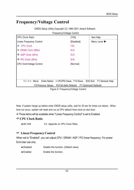
Figure 9: Frequency/Voltage Control
CMOS Setup Utility-Copyright (C) 1984-2001 Award SoftwareFrequency/Voltage Control
CPU Clock Ratio [15X] Item HelpLinear Frequency Control [Disabled] Menu Level
CPU Clock 100 DRAM Clock (MHz) N/A
AGP Clock (MHz) N/A
PCI Clock (MHz) N/ACPU OverVoltage Control [Normal]
: Move Enter:Select +/-/PU/PD:Value F10:Save ESC:Exit F1:General HelpF5:Previous Values F6:Fail-Safe Defaults F7:Optimized Defaults
Note: If system hangs up before enter CMOS setup utility, wait for 20 sec for times out reboot . Whentime out occur, system will reset and run at CPU default Host clock at next boot.
Those items will be available when "Linear Frequency Control" is set to Enabled. CPU Clock Ratio
8X~24X It’s depends on CPU Clock Ratio.
Linear Frequency ControlWhen set to "Enabled", you can adjust CPU / DRAM / AGP / PCI linear frequency. For powerEnd-User use only.
Disabled Disable this function. (Default value)
Enabled Enable this function.

GA-8SIML Motherboard
4 6
DRAM Clock (MHz)
This feature allows you to adjust the DRAM frequency, When "Linear Frequency Control" is set toEnabled.
Please set DRAM Clock according to your requirement.
If you use DDR200 DRAM module, please set “DRAM Clock(MHz)” to 100. If you use DDR333DRAM module, please set “DRAM Clock(MHz)” to 166.
Incorrect using it may cause your system broken. For power End-User use only!
AGP Clock (MHz)
This feature allows you to adjust the AGP frequency, When "Linear Frequency Control" is set toEnabled.
Please set AGP Clock according to your requirement.
Incorrect using it may cause your system broken. For power End-User use only!
PCI Clock (MHz)
This feature allows you to adjust the PCI frequency, When "Linear Frequency Control" is set toEnabled.
Please set PCI Clock according to your requirement.
Incorrect using it may cause your system broken. For power End-User use only!
CPU OverVoltage ControlSupports adjustable CPU Vcore from 1.100V to 1.850V by 0.025V step.
(Default value: Normal)
BIOS Setup
4 7
Load Fail-Safe Defaults
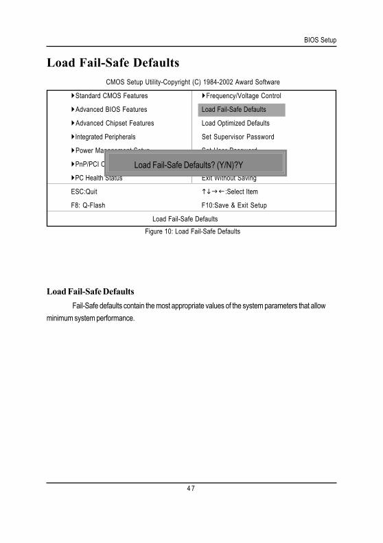
Load Fail-Safe DefaultsFail-Safe defaults contain the most appropriate values of the system parameters that allow
minimum system performance.
CMOS Setup Utility-Copyright (C) 1984-2002 Award Software
Standard CMOS Features Frequency/Voltage Control
Advanced BIOS Features Load Fail-Safe Defaults
Advanced Chipset Features Load Optimized Defaults
Integrated Peripherals Set Supervisor Password
Power Management Setup Set User Password
PnP/PCI Configurations Save & Exit Setup
PC Health Status Exit Without Saving
ESC:Quit :Select Item
F8: Q-Flash F10:Save & Exit Setup
Load Fail-Safe DefaultsFigure 10: Load Fail-Safe Defaults
Load Fail-Safe Defaults? (Y/N)?Y
GA-8SIML Motherboard
4 8
Load Optimized Defaults
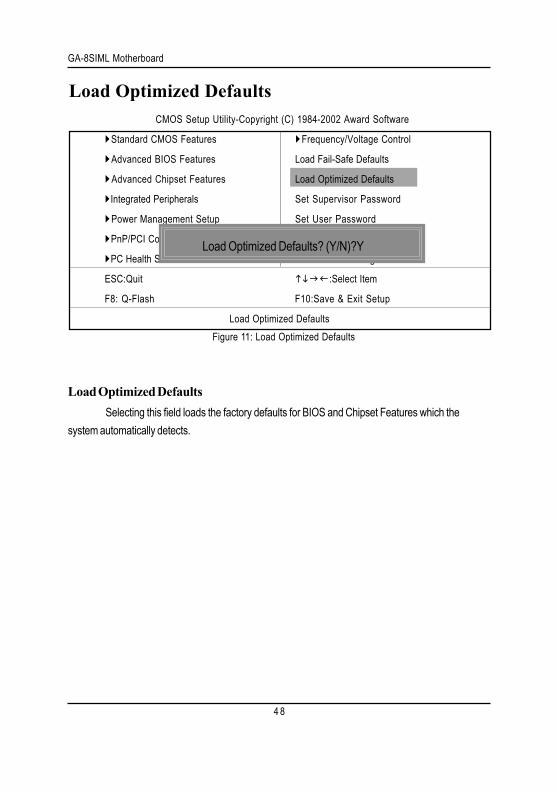
Load Optimized DefaultsSelecting this field loads the factory defaults for BIOS and Chipset Features which the
system automatically detects.
CMOS Setup Utility-Copyright (C) 1984-2002 Award Software
Standard CMOS Features Frequency/Voltage Control
Advanced BIOS Features Load Fail-Safe Defaults
Advanced Chipset Features Load Optimized Defaults
Integrated Peripherals Set Supervisor Password
Power Management Setup Set User Password
PnP/PCI Configurations Save & Exit Setup
PC Health Status Exit Without Saving
ESC:Quit :Select Item
F8: Q-Flash F10:Save & Exit Setup
Load Optimized DefaultsFigure 11: Load Optimized Defaults
Load Optimized Defaults? (Y/N)?Y
BIOS Setup
4 9
Set Supervisor/User Password
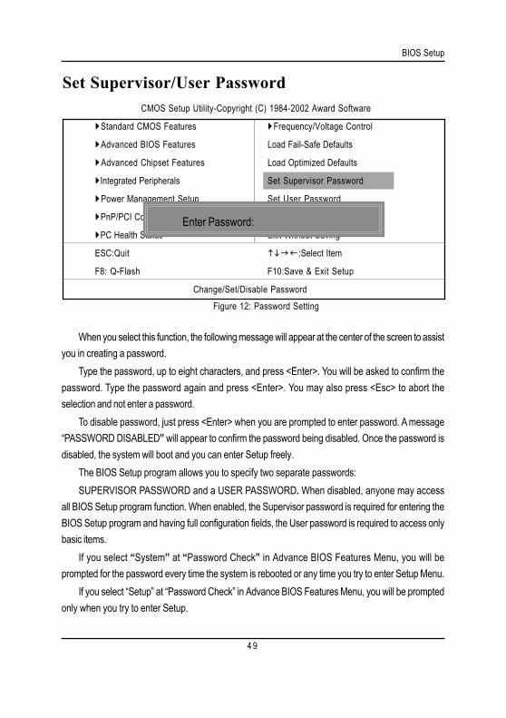
When you select this function, the following message will appear at the center of the screen to assistyou in creating a password.
Type the password, up to eight characters, and press <Enter>. You will be asked to confirm thepassword. Type the password again and press <Enter>. You may also press <Esc> to abort theselection and not enter a password.
To disable password, just press <Enter> when you are prompted to enter password. A message“PASSWORD DISABLED” will appear to confirm the password being disabled. Once the password isdisabled, the system will boot and you can enter Setup freely.
The BIOS Setup program allows you to specify two separate passwords:SUPERVISOR PASSWORD and a USER PASSWORD. When disabled, anyone may access
all BIOS Setup program function. When enabled, the Supervisor password is required for entering theBIOS Setup program and having full configuration fields, the User password is required to access onlybasic items.
If you select “System” at “Password Check” in Advance BIOS Features Menu, you will beprompted for the password every time the system is rebooted or any time you try to enter Setup Menu.
If you select “Setup” at “Password Check” in Advance BIOS Features Menu, you will be promptedonly when you try to enter Setup.
CMOS Setup Utility-Copyright (C) 1984-2002 Award Software
Standard CMOS Features Frequency/Voltage Control
Advanced BIOS Features Load Fail-Safe Defaults
Advanced Chipset Features Load Optimized Defaults
Integrated Peripherals Set Supervisor Password
Power Management Setup Set User Password
PnP/PCI Configurations Save & Exit Setup
PC Health Status Exit Without Saving
ESC:Quit :Select Item
F8: Q-Flash F10:Save & Exit Setup
Change/Set/Disable PasswordFigure 12: Password Setting
Enter Password:
GA-8SIML Motherboard
5 0
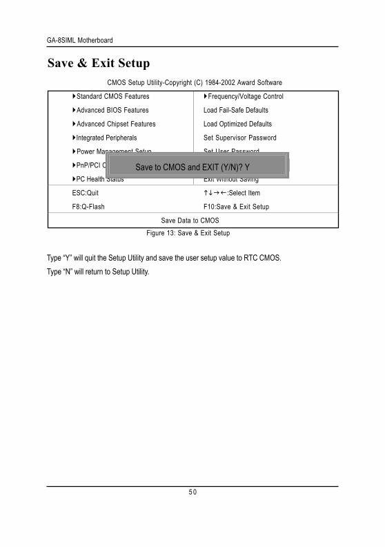
Save & Exit Setup
Type “Y” will quit the Setup Utility and save the user setup value to RTC CMOS.Type “N” will return to Setup Utility.
CMOS Setup Utility-Copyright (C) 1984-2002 Award Software
Standard CMOS Features Frequency/Voltage Control
Advanced BIOS Features Load Fail-Safe Defaults
Advanced Chipset Features Load Optimized Defaults
Integrated Peripherals Set Supervisor Password
Power Management Setup Set User Password
PnP/PCI Configurations Save & Exit Setup
PC Health Status Exit Without Saving
ESC:Quit :Select Item
F8:Q-Flash F10:Save & Exit Setup
Save Data to CMOSFigure 13: Save & Exit Setup
Save to CMOS and EXIT (Y/N)? Y
BIOS Setup
5 1
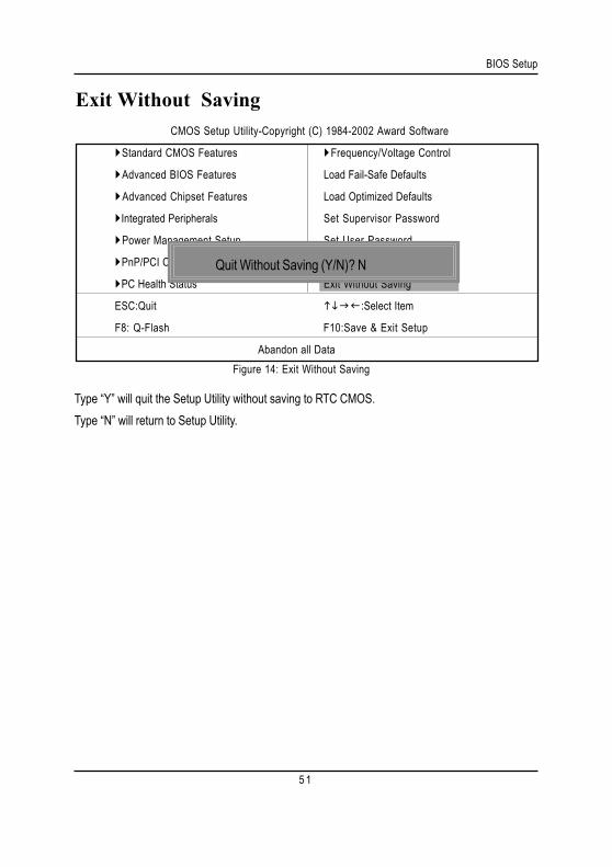
Exit Without Saving
Type “Y” will quit the Setup Utility without saving to RTC CMOS.Type “N” will return to Setup Utility.
CMOS Setup Utility-Copyright (C) 1984-2002 Award Software
Standard CMOS Features Frequency/Voltage Control
Advanced BIOS Features Load Fail-Safe Defaults
Advanced Chipset Features Load Optimized Defaults
Integrated Peripherals Set Supervisor Password
Power Management Setup Set User Password
PnP/PCI Configurations Save & Exit Setup
PC Health Status Exit Without Saving
ESC:Quit :Select Item
F8: Q-Flash F10:Save & Exit Setup
Abandon all DataFigure 14: Exit Without Saving
Quit Without Saving (Y/N)? N
GA-8SIML Motherboard
5 2
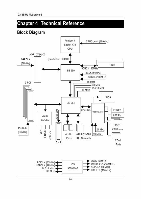
Revision HistoryChapter 4 Technical ReferenceBlock Diagram
Pentium 4Socket 478
CPU
SiS 650
AC97CODEC
SiS 961
CPUCLK+/- (100MHz)
System Bus 100MHz
DDR100/133/166MHz
ZCLK (66MHz)HCLK+/- (100MHz)
66 MHz33 MHz14.318 MHz
48 MHz
24 MHz33 MHz
LPC BUS
AGP 1X/2X/4X
AGPCLK(66MHz)
3 PCI
PCICLK(33MHz)
AC97
Link
MIC
LINE
-INLI
NE-O
UT
4 USBPorts
ATA33/66/100IDE Channels
Floppy
LPT Port
PS/2 KB/Mouse
COM Ports
CNR
ICS952001AF
ZCLK (66MHz)CPUCLK+/- (100MHz)AGPCLK (66MHz)HCLK+/- (100MHz)
PCICLK (33MHz)USBCLK (48MHz)
14.318 MHz33 MHz
BIOS
W83697HF
5 3
Technical Reference
@ BIOSTM IntroductionGigabyte announces @ BIOSWindows BIOS live update utility
Have you ever updated BIOS by yourself? Or likemany other people, you just know what BIOS is,but always hesitate to update it? Because you thinkupdating newest BIOS is unnecessary and actuallyyou don’t know how to update it.
Maybe not like others, you are very experienced in BIOS updating and spend quite a lot of timeto do it. But of course you don’t like to do it too much. First, download different BIOS from website andthen switch the operating system to DOS mode. Secondly, use different flash utility to update BIOS.The above process is not a interesting job. Besides, always be carefully to store the BIOS sourcecode correctly in your disks as if you update the wrong BIOS, it will be a nightmare.
Certainly, you wonder why motherboard vendors could not just do something right to save yourtime and effort and save you from the lousy BIOS updating work? Here it comes! Now Gigabyteannounces @BIOS—the first Windows BIOS live update utility. This is a smart BIOS updatesoftware. It could help you to download the BIOS from internetand update it. Not like the other BIOSupdate software, it’s a Windows utility. With the help of “@BIOS’, BIOS updating is no more than aclick.
Besides, no matter which mainboard you are using, if it’s a Gigabyte’s product*, @BIOS helpyou to maintain the BIOS. This utility could detect your correct mainboard model and help you tochoose the BIOS accordingly. It then downloads the BIOS from the nearest Gigabyte ftp siteautomatically. There are several different choices; you could use “Internet Update” to download andupdate your BIOS directly. Or you may want to keep a backup for your current BIOS, just choose“Save Current BIOS” to save it first. You make a wise choice to use Gigabyte, and @BIOS updateyour BIOS smartly. You are now worry free from updating wrong BIOS, and capable to maintain andmanage your BIOS easily. Again, Gigabyte’s innovative product erects a milestone in mainboardindustries.
For such a wonderful software, how much it costs? Impossible! It’s free! Now, if you buy aGigabyte’s motherboard, you could find this amazing software in the attached driver CD. But pleaseremember, connected to internet at first, then you could have a internet BIOS update from yourGigabyte @BIOS.
GA-8SIML Motherboard
5 4
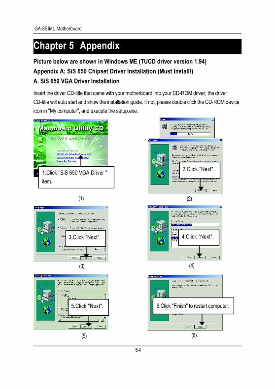
Revision HistoryChapter 5 AppendixPicture below are shown in Windows ME (TUCD driver version 1.94)Appendix A: SiS 650 Chipset Driver Installation (Must Install!)A. SiS 650 VGA Driver Installation
Insert the driver CD-title that came with your motherboard into your CD-ROM driver, the driverCD-title will auto start and show the installation guide. If not, please double click the CD-ROM deviceicon in "My computer", and execute the setup.exe.
(4)(3)
(2)(1)
1.Click "SiS 650 VGA Driver "item.
2.Click "Next".
4.Click "Next".3.Click "Next".
6.Click "Finish" to restart computer.
(6)(5)
5.Click "Next".

5 5
Appendix
B: SiS AGP Driver Installation
Insert the driver CD-title that came with your motherboard into your CD-ROM driver, the driverCD-title will auto start and show the installation guide. If not, please double click the CD-ROM deviceicon in "My computer", and execute the setup.exe.
(4)(3)
(2)(1)
1.Click "SiS AGP Driver item.
3.Click "Next".2.Click "Next".
4.Click "Finish" to restart computer.
(6)(5)
GA-8SIML Motherboard
5 6
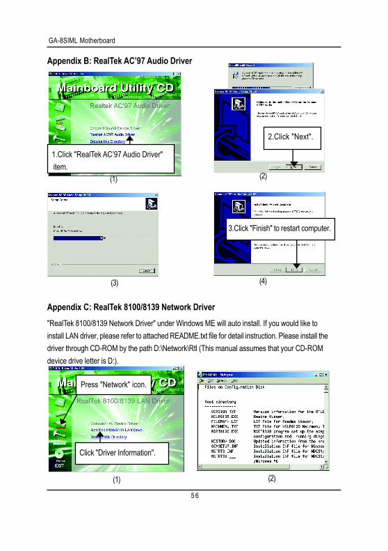
Revision HistoryAppendix B: RealTek AC’97 Audio Driver
(1)
1.Click "RealTek AC’97 Audio Driver" item.
(2)
(3)
3.Click "Finish" to restart computer.
(4)
2.Click "Next".
Revision HistoryAppendix C: RealTek 8100/8139 Network Driver"RealTek 8100/8139 Network Driver" under Windows ME will auto install. If you would like toinstall LAN driver, please refer to attached README.txt file for detail instruction. Please install thedriver through CD-ROM by the path D:\Network\Rtl (This manual assumes that your CD-ROMdevice drive letter is D:).
(1) (2)
Press "Network" icon.
Click "Driver Information".
5 7
Appendix
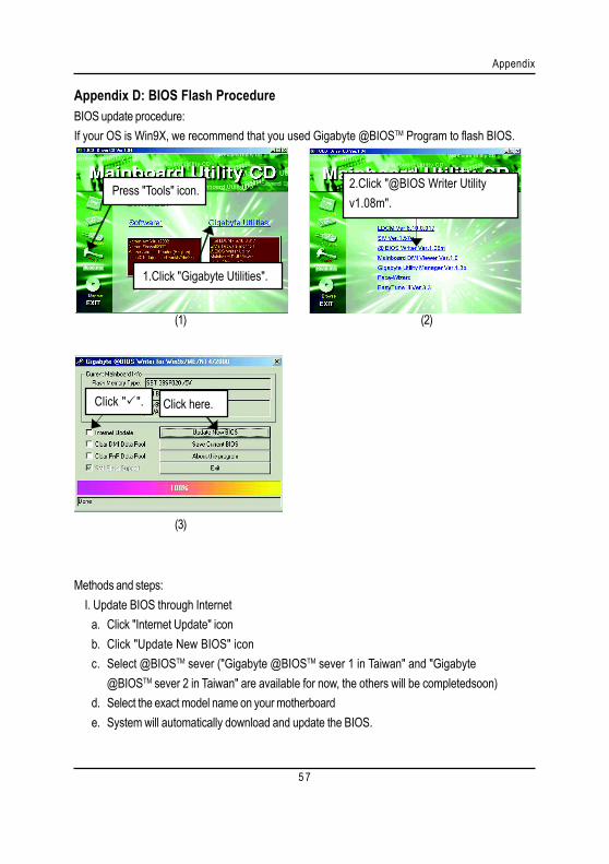
Appendix D: BIOS Flash ProcedureBIOS update procedure:If your OS is Win9X, we recommend that you used Gigabyte @BIOSTM Program to flash BIOS.
Methods and steps: I. Update BIOS through Internet
a. Click "Internet Update" iconb. Click "Update New BIOS" iconc. Select @BIOSTM sever ("Gigabyte @BIOSTM sever 1 in Taiwan" and "Gigabyte
@BIOSTM sever 2 in Taiwan" are available for now, the others will be completedsoon)d. Select the exact model name on your motherboarde. System will automatically download and update the BIOS.
(3)
(1) (2)
Press "Tools" icon.
1.Click "Gigabyte Utilities".
2.Click "@BIOS Writer Utilityv1.08m".
Click " ". Click here.
GA-8SIML Motherboard
5 8
II. Update BIOS NOT through Internet:a. Do not click "Internet Update" iconb. Click "Update New BIOS"c. Please select "All Files" in dialog box while opening the old file.d. Please search for BIOS unzip file, downloading from internet or any other methods (such as:
8SIML.F1).e. Complete update process following the instruction.
III. Save BIOSIn the very beginning, there is "Save Current BIOS" icon shown in dialog box. It means to savethe current BIOS version.
IV. Check out supported motherboard and Flash ROM:In the very beginning, there is "About this program" icon shown in dialog box. It can help youcheck out which kind of motherboard and which brand of Flash ROM are supported.
Note:a. In method I, if it shows two or more motherboard's model names to be selected, please make
sure your motherboard's model name again. Selecting wrong model name will cause thesystem unbooted.
b. In method II, be sure that motherboard's model name in BIOS unzip file are the same as yourmotherboard's. Otherwise, your system won't boot.
c. In method I, if the BIOS file you need cannot be found in @BIOSTM server, please go ontoGigabyte's web site for downloading and updating it according to method II.
d. Please note that any interruption during updating will cause system unbooted
5 9
Appendix
We use GA-7VTX motherboard and Flash841 BIOS flash utility as example.Please flash the BIOS according to the following procedures if you are now under the DOS mode.Flash BIOS Procedure:STEP 1:(1) Please make sure you have set "Auto" for BIOS Feature Setup (BIOS Flash Protection). For
more detail please refer to page 28.(2) Please make sure your system has installed the extraction utility such as winzip or pkunzip.
Firstly you have to install the extraction utility such as winzip or pkunzip for unzip the files. Both ofthese utilities are available on many shareware download pages like http://www.shareware.cnet.com
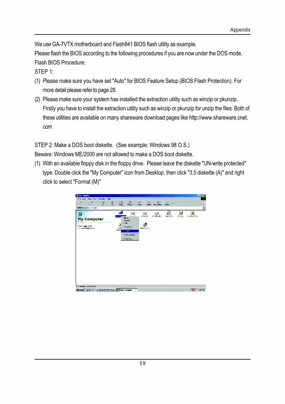
STEP 2: Make a DOS boot diskette. (See example: Windows 98 O.S.)Beware: Windows ME/2000 are not allowed to make a DOS boot diskette.(1) With an available floppy disk in the floppy drive. Please leave the diskette "UN-write protected"
type. Double click the "My Computer" icon from Desktop, then click "3.5 diskette (A)" and rightclick to select "Format (M)"
GA-8SIML Motherboard
6 0
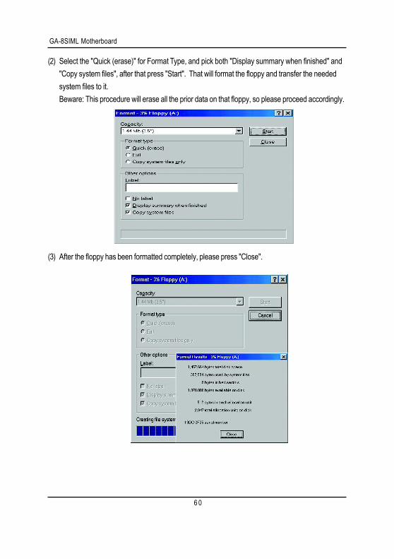
(2) Select the "Quick (erase)" for Format Type, and pick both "Display summary when finished" and"Copy system files", after that press "Start". That will format the floppy and transfer the neededsystem files to it.Beware: This procedure will erase all the prior data on that floppy, so please proceed accordingly.
(3) After the floppy has been formatted completely, please press "Close".
6 1
Appendix
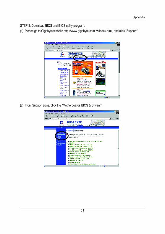
STEP 3: Download BIOS and BIOS utility program.(1) Please go to Gigabyte website http://www.gigabyte.com.tw/index.html, and click "Support".
(2) From Support zone, click the "Motherboards BIOS & Drivers".
GA-8SIML Motherboard
6 2
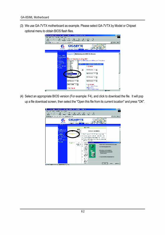
(3) We use GA-7VTX motherboard as example. Please select GA-7VTX by Model or Chipsetoptional menu to obtain BIOS flash files.
(4) Select an appropriate BIOS version (For example: F4), and click to download the file. It will popup a file download screen, then select the "Open this file from its current location" and press "OK".
6 3
Appendix
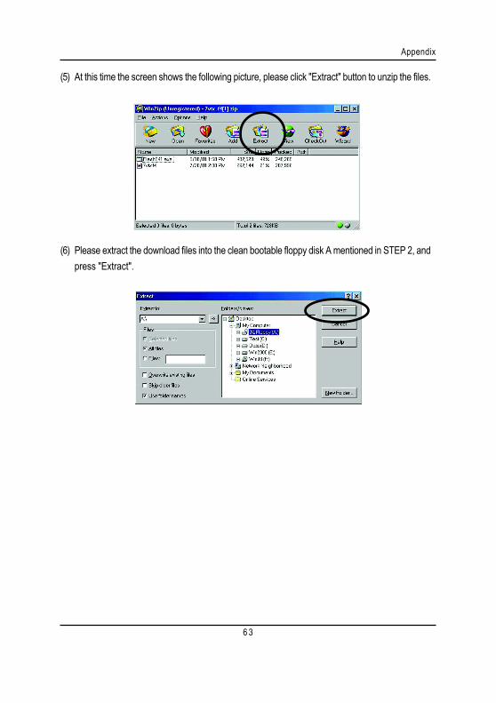
(5) At this time the screen shows the following picture, please click "Extract" button to unzip the files.
(6) Please extract the download files into the clean bootable floppy disk A mentioned in STEP 2, andpress "Extract".

GA-8SIML Motherboard
6 4
STEP 4: Make sure the system will boot from the floppy disk.(1) Insert the floppy disk (contains bootable program and unzip file) into the floppy drive A. Then,
restart the system. The system will boot from the floppy disk. Please press <DEL> key to enterBIOS setup main menu when system is boot up.
(2) Once you enter the BIOS setup utility, the main menu will appear on the screen. Use the arrowsto highlight the item "BIOS FEATURES SETUP".
7VTX F1Check System Health OKAMD-Athlon(tm)Processor-900MHzChecking NVRAM...262144KB
Wait...Press F1 to enter Dual BIOS Utility. Press ESC to quitPress any key to contiune
( C ) American Megatrends Inc.,63-0001-001199-00101111-071595-VIA_K7-GA7VTX1-F
American Release:09/16/99Megatrends AMIBIOS (C) 1999 American Megatrend
AMIBIOS SIMPLE SETUP UTILITY - VERSION 1.24b(C) 1999 American Megatrends, Inc. All Rights Reserved
STANDARD CMOS SETUP INTEGRATED PERIPHERALS
BIOS FEATURES SETUP HARDWARE MONITOR & MISC SETUP
CHIPSET FEATURES SETUP SUPERVISOR PASSWORD
POWER MANAGEMENT SETUP USER PASSWORD
PNP / PCI CONFIGURATION IDE HDD AUTO DETECTION
LOAD BIOS DEFAULTS SAVE & EXIT SETUP
LOAD SETUP DEFAULTS EXIT WITHOUT SAVING
ESC: Quit : Select Item (Shift)F2 : Change Color F5: Old Values
F6: Load BIOS Defaults F7: Load Setup Defaults F10:Save & Exit
Time, Date , Hard Disk Type…

6 5
Appendix
(3) Press "Enter" to enter "BIOS FEATURES SETUP" menu. Use the arrows to highlight the item"1st Boot Device", and then use the "Page Up" or "Page Down" keys to select "Floppy".
(4) Press "ESC" to go back to previous screen. Use the arrows to highlight the item "SAVE & EXITSETUP" then press "Enter". System will ask "SAVE to CMOS and EXIT (Y/N)?" Press "Y"and "Enter" keys to confirm. Now the system will reboot automatically, the new BIOS settingwill be taken effect next boot-up.
AMIBIOS SETUP - BIOS FEATURES SETUP( C ) 2001 American Megatrends, Inc. All Rights Reserved
1st Boot Device : Floppy2nd Boot Device : IDE-03rd Boot Device : CDROMS.M.A.R.T. for Hard Disks : DisabledBootUp Num-Lock : On ESC: Quit : Select ItemFloppy Drive Seek : Disabled F1 : Help PU/PD/+/- : ModifyPassword Check : Setup F5 : Old Values (Shift)F2: Color
F6 : Load BIOS DefaultsF7 : Load Setup Defaults
AMIBIOS SIMPLE SETUP UTILITY - VERSION 1.24b(C) 2001 American Megatrends, Inc. All Rights Reserved
STANDARD CMOS SETUP INTEGRATED PERIPHERALS
BIOS FEATURES SETUP HARDWARE MONITOR & MISC SETUP
CHIPSET FEATURES SETUP SUPERVISOR PASSWORD
POWER MANAGEMENT SETUP USER PASSWORD
PNP / PCI CONFIGURATION IDE HDD AUTO DETECTION
LOAD BIOS DEFAULTS SAVE & EXIT SETUP
LOAD SETUP DEFAULTS EXIT WITHOUT SAVING
ESC: Quit : Select Item (Shift)F2 : Change Color F5: Old Values
F6: Load BIOS Defaults F7: Load Setup Defaults F10:Save & Exit
Save Data to CMOS & Exit SETUP
Save to CMOS and EXIT (Y/N)? Y
GA-8SIML Motherboard
6 6
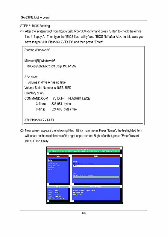
STEP 5: BIOS flashing.(1) After the system boot from floppy disk, type "A:\> dir/w" and press "Enter" to check the entire
files in floppy A. Then type the "BIOS flash utility" and "BIOS file" after A:\>. In this case youhave to type "A:\> Flash841 7VTX.F4" and then press "Enter".
(2) Now screen appears the following Flash Utility main menu. Press "Enter", the highlighted itemwill locate on the model name of the right-upper screen. Right after that, press "Enter" to startBIOS Flash Utility.
Starting Windows 98…
Microsoft(R) Windows98 © Copyright Microsoft Corp 1981-1999
A:\> dir/w Volume in drive A has no labelVolume Serial Number is 16EB-353DDirectory of A:\COMMAND.COM 7VTX.F4 FLASH841.EXE 3 file(s) 838,954 bytes 0 dir(s) 324,608 bytes free
A:\> Flash841 7VTX.F4

6 7
Appendix
(3) It will pop up a screen and asks "Are you sure to flash the BIOS?" Press [Enter] to continue theprocedure, or press [ESC] to quit.Beware: Please do not turn off the system while you are upgrading BIOS. It will render yourBIOS corrupted and system totally inoperative.
(4) The BIOS flash completed. Please press [ESC] to exit Flash Utility.
Are you sure to flash the BIOS?[Enter] to continue Or [Esc] to cancel?
EXIT?[Enter] to continue Or [Esc] to cancel?

GA-8SIML Motherboard
6 8
STEP 6: Load BIOS defaults.Normally the system redetects all devices after BIOS has been upgraded. Therefore, we highlyrecommend reloading the BIOS defaults after BIOS has been upgraded. This important stepresets everything after the flash.
(1) Take out the floppy diskette from floppy drive, and then restart the system. The boot up screen willindicate your motherboard model and current BIOS version.
(2) Don't forget to press <DEL> key to enter BIOS setup again when system is boot up. Use thearrows to highlight the item "LOAD SETUP DEFAULTS" then press "Enter". System will ask"Load Setup Defaults (Y/N)?" Press "Y" and "Enter" keys to confirm.
7VTX F4Check System Health OKAMD-Athlon(tm)Processor-900MHzChecking NVRAM...262144KB
Wait...Press F1 to enter Dual BIOS Utility. Press ESC to quitPress any key to contiune
( C ) American Megatrends Inc.,63-0001-001199-00101111-071595-VIA_K7-GA7VTX1-F
American Release:09/16/99Megatrends AMIBIOS (C) 1999 American Megatrend
AMIBIOS SIMPLE SETUP UTILITY - VERSION 1.24b(C) 2001 American Megatrends, Inc. All Rights Reserved
STANDARD CMOS SETUP INTEGRATED PERIPHERALS
BIOS FEATURES SETUP HARDWARE MONITOR & MISC SETUP
CHIPSET FEATURES SETUP SUPERVISOR PASSWORD
POWER MANAGEMENT SETUP USER PASSWORD
PNP / PCI CONFIGURATION IDE HDD AUTO DETECTION
LOAD BIOS DEFAULTS SAVE & EXIT SETUP
LOAD SETUP DEFAULTS EXIT WITHOUT SAVING
ESC: Quit : Select Item (Shift)F2 : Change Color F5: Old Values
F6: Load BIOS Defaults F7: Load Setup Defaults F10:Save & Exit
Load Setup Defaults
Load Setup Defaults? (Y/N)?N
6 9
Appendix
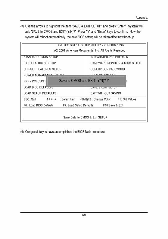
(3) Use the arrows to highlight the item "SAVE & EXIT SETUP" and press "Enter". System willask "SAVE to CMOS and EXIT (Y/N)?" Press "Y" and "Enter" keys to confirm. Now thesystem will reboot automatically, the new BIOS setting will be taken effect next boot-up.
(4) Congratulate you have accomplished the BIOS flash procedure.
AMIBIOS SIMPLE SETUP UTILITY - VERSION 1.24b(C) 2001 American Megatrends, Inc. All Rights Reserved
STANDARD CMOS SETUP INTEGRATED PERIPHERALS
BIOS FEATURES SETUP HARDWARE MONITOR & MISC SETUP
CHIPSET FEATURES SETUP SUPERVISOR PASSWORD
POWER MANAGEMENT SETUP USER PASSWORD
PNP / PCI CONFIGURATION IDE HDD AUTO DETECTION
LOAD BIOS DEFAULTS SAVE & EXIT SETUP
LOAD SETUP DEFAULTS EXIT WITHOUT SAVING
ESC: Quit : Select Item (Shift)F2 : Change Color F5: Old Values
F6: Load BIOS Defaults F7: Load Setup Defaults F10:Save & Exit
Save Data to CMOS & Exit SETUP
Save to CMOS and EXIT (Y/N)? Y
GA-8SIML Motherboard
7 0
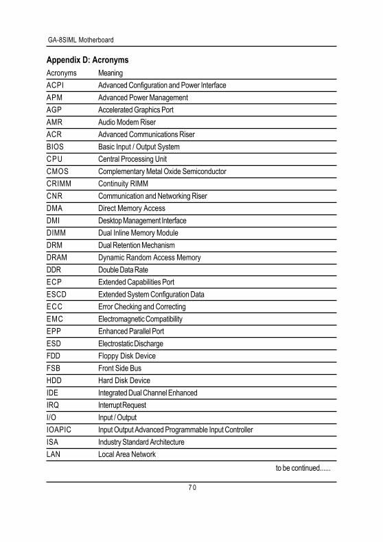
Appendix D: AcronymsAcronyms MeaningACPI Advanced Configuration and Power InterfaceAPM Advanced Power ManagementAGP Accelerated Graphics PortAMR Audio Modem RiserACR Advanced Communications RiserBIOS Basic Input / Output SystemCPU Central Processing UnitCMOS Complementary Metal Oxide SemiconductorCRIMM Continuity RIMMCNR Communication and Networking RiserDMA Direct Memory AccessDMI Desktop Management InterfaceDIMM Dual Inline Memory ModuleDRM Dual Retention MechanismDRAM Dynamic Random Access MemoryDDR Double Data RateECP Extended Capabilities PortESCD Extended System Configuration DataECC Error Checking and CorrectingEMC Electromagnetic CompatibilityEPP Enhanced Parallel PortESD Electrostatic DischargeFDD Floppy Disk DeviceFSB Front Side BusHDD Hard Disk DeviceIDE Integrated Dual Channel EnhancedIRQ Interrupt RequestI/O Input / OutputIOAPIC Input Output Advanced Programmable Input ControllerISA Industry Standard ArchitectureLAN Local Area Network
to be continued......
7 1
Appendix
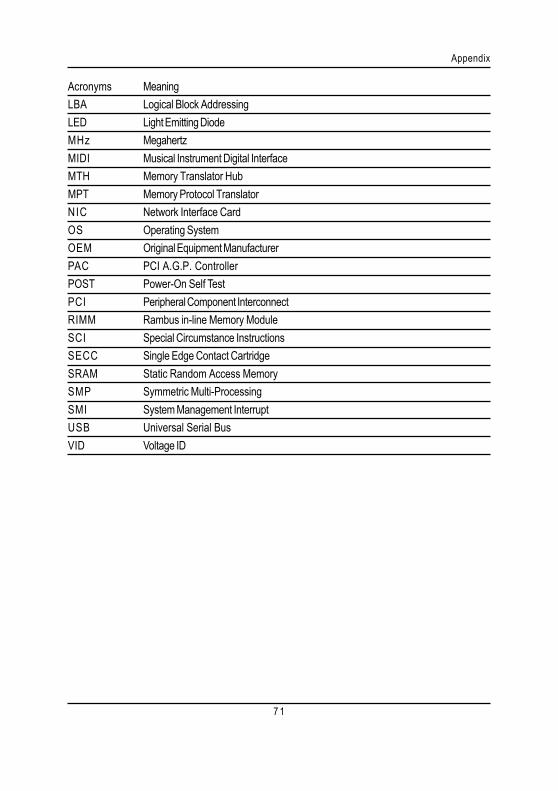
Acronyms MeaningLBA Logical Block AddressingLED Light Emitting DiodeMHz MegahertzMIDI Musical Instrument Digital InterfaceMTH Memory Translator HubMPT Memory Protocol TranslatorNIC Network Interface CardOS Operating SystemOEM Original Equipment ManufacturerPAC PCI A.G.P. ControllerPOST Power-On Self TestPCI Peripheral Component InterconnectRIMM Rambus in-line Memory ModuleSCI Special Circumstance InstructionsSECC Single Edge Contact CartridgeSRAM Static Random Access MemorySMP Symmetric Multi-ProcessingSMI System Management InterruptUSB Universal Serial BusVID Voltage ID
GA-8SIML Motherboard
7 2
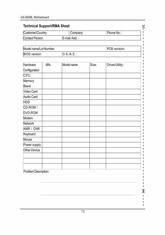
Technical Support/RMA SheetCustomer/Country: Company: Phone No.:Contact Person: E-mail Add. :
Model name/Lot Number: PCB revision:BIOS version: O.S./A.S.:
Hardware Mfs. Model name Size: Driver/Utility:ConfigurationCPUMemoryBrandVideo CardAudio CardHDDCD-ROM /DVD-ROMModemNetworkAMR / CNRKeyboardMousePower supplyOther Device
Problem Description: