most common mistakes tutorial - v01 · 2013. 12. 12. · most common mistakes tutorial - v1.0 7/17...
TRANSCRIPT
MMoosstt CCoommmmoonn MMiissttaakkeess TTuuttoorriiaall FFoorr GGooooggllee SSkkeettcchhuupp
Most Common Mistakes Tutorial - V1.0 2/17
Foreword Welcome to the most common mistakes tutorial for Google Sketchup. This is a tutorial about the most common mistakes that are made in a 3D model using the Google Sketchup program for 3D modeling. It shows what kinds of different mistakes there are, how to find or recognize them and how to fix them. The purpose of this tutorial is to improve the quality of your models by showing what affects that quality. It should give you an idea about your own level of modeling and provides a manual to judge the quality of other people's models. This tutorial not only looks at geometry mistakes but also mistakes that affect the efficiency, file size and cleanness of a model. The tutorial is not meant to teach the basic tools of Sketchup. There are lots of other recourses on the web where you can find how to use the basic tools. A printable .pdf file with all the basic tools and commands can be found in the map where Sketchup is installed. Look for a file called "QuickReferenceCard.pdf". Good luck modeling
General information This tutorial was written by J-m@n (http://www.j-man.nl) with the help of the moderator group (Bluesdog, Logan, OZ the Wiz and Rahul Desai) of the Google Sketchup 3D Challenge Blog. For this tutorial Google Sketchup version 6 was used. Google Sketchup is a registered trademark of Google Inc. Download or purchase the program here: Free version: http://sketchup.google.com/product_suf.html Pro Version: http://www.sketchup.com/cgi-bin/istore Support for Google Sketchup: http://sketchup.google.com/support Related links: Sketchup homepage http://www.sketchup.com 3D Warehouse http://sketchup.google.com/3dwarehouse 3D Challenges http://sketchup3dchallenge.blogspot.com/ Official Sketchup blog http://sketchupdate.blogspot.com/ Suwiki http://suwiki.org Sketchucation http://www.sketchucation.com Note: These above links may change in the future and are not guaranteed to work.

Most Common Mistakes Tutorial - V1.0 3/17
Index Chapter Page 1. Geometry mistakes 4
1.1 Excessive geometry 4 1.2 Small dimension gaps 5 1.3 Subdivided surfaces 6 1.4 Unconnected lines 7 1.5 Wrong alignment 7 1.6 Zero thickness 8 1.7 Wrong proportions and scale 8
2. Groups and components mistakes 9
2.1 Mixed use of groups and components 9 2.2 Wrongly grouped geometry 10 2.3 Unused components 10 3. Smoothing and painting mistakes 11
3.1 Cylinders and rounded corners 11 3.2 Smoothed sharp corners 12 3.3 Imported images 12 3.4 Images on spheres 13 3.5 Unused colors and textures 13 4. Cleanness mistakes 14
4.1 Unused lines 14 4.2 Unused surfaces in shapes 15 4.3 Intersecting shapes 16 4.4 Reversed faces 16 Final words 17
Most Common Mistakes Tutorial - V1.0 4/17
1. Geometry mistakes In this chapter we will look at common mistakes which can be made while creating the geometry of the model. Most of these mistakes influence the final result and quality of the model, so it is a good thing to remember them while creating your model. Some of these mistakes are hard or almost impossible to fix without recreating whole parts of the model.
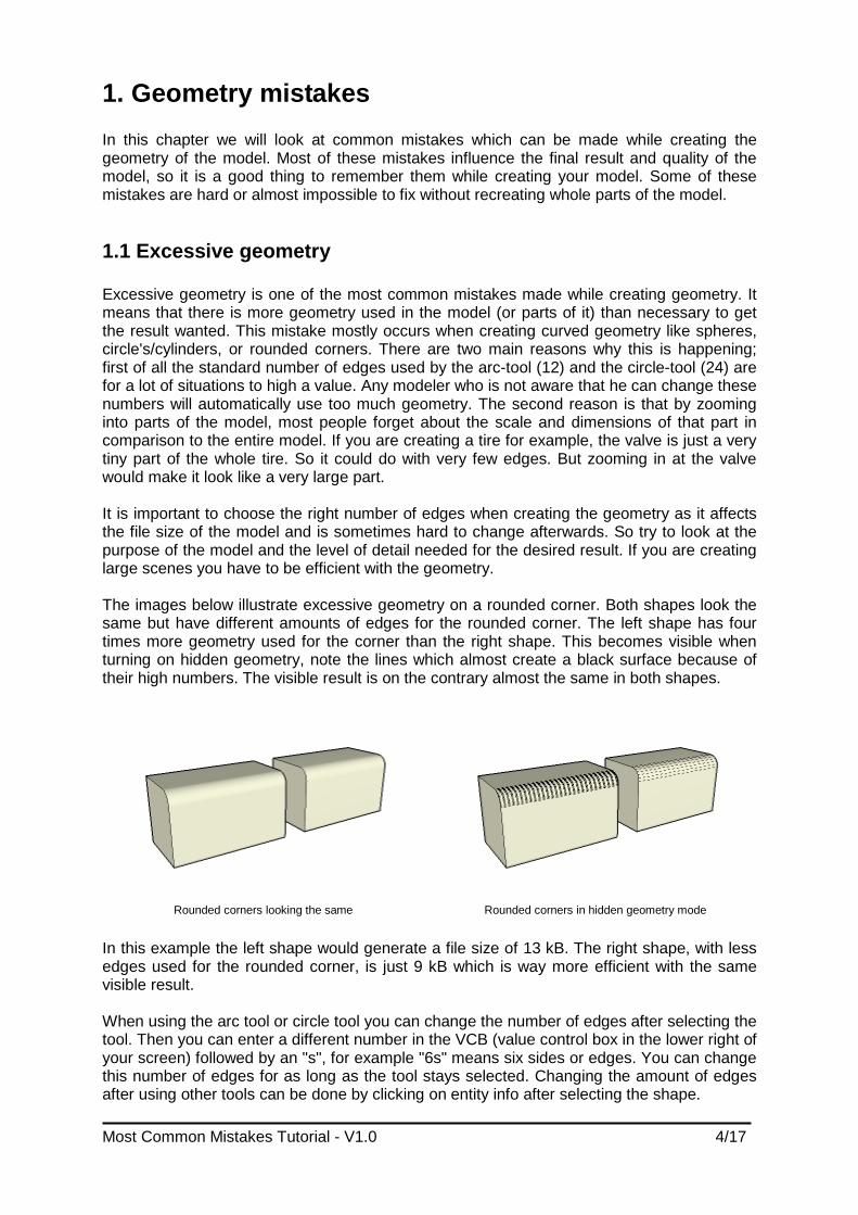
1.1 Excessive geometry Excessive geometry is one of the most common mistakes made while creating geometry. It means that there is more geometry used in the model (or parts of it) than necessary to get the result wanted. This mistake mostly occurs when creating curved geometry like spheres, circle's/cylinders, or rounded corners. There are two main reasons why this is happening; first of all the standard number of edges used by the arc-tool (12) and the circle-tool (24) are for a lot of situations to high a value. Any modeler who is not aware that he can change these numbers will automatically use too much geometry. The second reason is that by zooming into parts of the model, most people forget about the scale and dimensions of that part in comparison to the entire model. If you are creating a tire for example, the valve is just a very tiny part of the whole tire. So it could do with very few edges. But zooming in at the valve would make it look like a very large part. It is important to choose the right number of edges when creating the geometry as it affects the file size of the model and is sometimes hard to change afterwards. So try to look at the purpose of the model and the level of detail needed for the desired result. If you are creating large scenes you have to be efficient with the geometry. The images below illustrate excessive geometry on a rounded corner. Both shapes look the same but have different amounts of edges for the rounded corner. The left shape has four times more geometry used for the corner than the right shape. This becomes visible when turning on hidden geometry, note the lines which almost create a black surface because of their high numbers. The visible result is on the contrary almost the same in both shapes.
Rounded corners looking the same Rounded corners in hidden geometry mode
In this example the left shape would generate a file size of 13 kB. The right shape, with less edges used for the rounded corner, is just 9 kB which is way more efficient with the same visible result. When using the arc tool or circle tool you can change the number of edges after selecting the tool. Then you can enter a different number in the VCB (value control box in the lower right of your screen) followed by an "s", for example "6s" means six sides or edges. You can change this number of edges for as long as the tool stays selected. Changing the amount of edges after using other tools can be done by clicking on entity info after selecting the shape.

Most Common Mistakes Tutorial - V1.0 5/17
1.2 Small dimension gaps Small dimension gaps are missing pieces (gaps) or missing parts of geometry that appear in a surface after using the follow me tool on a object with (very) small dimensions or while intersecting shapes with each other. This is a problem caused by Sketchup itself and can't be solved without rewriting the program. But fortunately there is a way around this problem. The left image below shows the creation of a shape using the follow me tool. In this case the length of the horizontal line of the start shape is 20mm. After using the follow me tool and deleting the top surface we can see a gap (red arrow) in the bottom of the shape. This was caused by the small dimensions of the start shape and can't be fixed. The only way to get around this problem is to scale the start geometry before using the follow me tool or intersecting command. If the start geometry would be scaled with a factor 10 the problem wouldn't occur. This way the dimensions are big enough for Sketchup to work with. After creating the desired shape just scale it back to it's original dimensions with the scale factor 0,1. If the size of your model is really small, like fractions of a millimeter, than you might have to use an even larger scale factor like 100. I would suggest using scale factors of 10, 100, 1000 etcetera as it only shifts the comma instead of creating totally different measurements.
Small dimension gaps Gap after intersecting two cylinders
The right image above shows an example of the same problem occurring after intersecting two shapes, in this case two cylinders, with small dimensions. Although the gap is a triangle and should be easily fixed with a simple line it can't be fixed unless the whole shape (both of the cylinders) is rescaled to bigger dimensions. After rescaling, draw a line over one of the edges of the gap and it should close. Finally rescale the shape back to its original size.
Most Common Mistakes Tutorial - V1.0 6/17
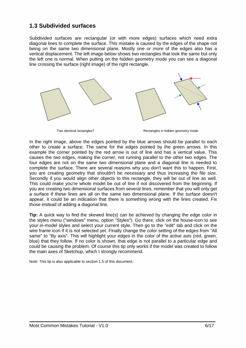
1.3 Subdivided surfaces Subdivided surfaces are rectangular (or with more edges) surfaces which need extra diagonal lines to complete the surface. This mistake is caused by the edges of the shape not being on the same two dimensional plane. Mostly one or more of the edges also has a vertical displacement. The left image below shows two rectangles that look the same but only the left one is normal. When putting on the hidden geometry mode you can see a diagonal line crossing the surface (right image) of the right rectangle.
Two identical rectangles? Rectangles in hidden geometry mode
In the right image, above the edges pointed by the blue arrows should be parallel to each other to create a surface. The same for the edges pointed by the green arrows. In this example the corner pointed by the red arrow is out of line and has a vertical value. This causes the two edges, making the corner, not running parallel to the other two edges. The four edges are not on the same two dimensional plane and a diagonal line is needed to complete the surface. There are several reasons why you don't want this to happen. First, you are creating geometry that shouldn't be necessary and thus increasing the file size. Secondly if you would align other objects to this rectangle, they will be out of line as well. This could make you're whole model be out of line if not discovered from the beginning. If you are creating two dimensional surfaces from several lines, remember that you will only get a surface if these lines are all on the same two dimensional plane. If the surface doesn't appear, it could be an indication that there is something wrong with the lines created. Fix those instead of adding a diagonal line. Tip: A quick way to find the skewed line(s) can be achieved by changing the edge color in the styles menu ("windows" menu, option "Styles"). Go there, click on the house-icon to see your in-model styles and select your current style. Then go to the "edit" tab and click on the wire frame icon if it is not selected yet. Finally change the color setting of the edges from "All same" to "By axis". This will highlight your edges in the color of the active axis (red, green, blue) that they follow. If no color is shown, that edge is not parallel to a particular edge and could be causing the problem. Of course this tip only works if the model was created to follow the main axes of Sketchup, which I strongly recommend. Note: This tip is also applicable to section 1.5 of this document.
Most Common Mistakes Tutorial - V1.0 7/17
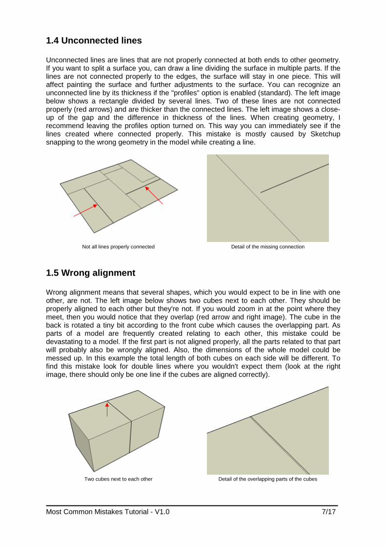
1.4 Unconnected lines Unconnected lines are lines that are not properly connected at both ends to other geometry. If you want to split a surface you, can draw a line dividing the surface in multiple parts. If the lines are not connected properly to the edges, the surface will stay in one piece. This will affect painting the surface and further adjustments to the surface. You can recognize an unconnected line by its thickness if the "profiles" option is enabled (standard). The left image below shows a rectangle divided by several lines. Two of these lines are not connected properly (red arrows) and are thicker than the connected lines. The left image shows a close-up of the gap and the difference in thickness of the lines. When creating geometry, I recommend leaving the profiles option turned on. This way you can immediately see if the lines created where connected properly. This mistake is mostly caused by Sketchup snapping to the wrong geometry in the model while creating a line.
Not all lines properly connected Detail of the missing connection
1.5 Wrong alignment Wrong alignment means that several shapes, which you would expect to be in line with one other, are not. The left image below shows two cubes next to each other. They should be properly aligned to each other but they're not. If you would zoom in at the point where they meet, then you would notice that they overlap (red arrow and right image). The cube in the back is rotated a tiny bit according to the front cube which causes the overlapping part. As parts of a model are frequently created relating to each other, this mistake could be devastating to a model. If the first part is not aligned properly, all the parts related to that part will probably also be wrongly aligned. Also, the dimensions of the whole model could be messed up. In this example the total length of both cubes on each side will be different. To find this mistake look for double lines where you wouldn't expect them (look at the right image, there should only be one line if the cubes are aligned correctly).
Two cubes next to each other Detail of the overlapping parts of the cubes

Most Common Mistakes Tutorial - V1.0 8/17
1.6 Zero thickness The zero thickness mistake means that parts of a model which should be three dimensional are only two dimensional. In the example image below, I created a table with three dimensional legs. The top of the table, on the contrary, is just a two dimensional surface. This causes several problems in the model. Firstly the realism. In the real world this part of the table would have a thickness. If you want the table to look like a real life object, it should also have a thickness in the model. Secondly, all the geometry connected to that surface will pierce through and stay visible. In this example shown below, the tops of the legs stay visible as they pierce through the surface (red circles). The right image below shows the same table but with thickness added. The table now looks more realistic, and there are no parts visible that are piercing through the top. When creating parts remember that everything has a thickness in the real world. Only omit the third dimension if it would cause excessive geometry in the model. As an example, adding thickness to a piece of paper on a desk would be useless, as the thickness would be too small to see.
Table top with zero thickness Table top with thickness
1.7 Wrong proportions and scale These mistakes affect the realism of a model compared to the real world object. The left image below shows the effect of wrong proportions compared to the right proportions. The head and legs of the left model are to long in height compared to its body. The Lego man on the right shows the proper proportions. The right image below shows the effect of a wrong scale in a model. The arm-rest of the couch is approximately 65cm high. This would make the Lego man in this model about 30cm high, which of course is not the reality. When creating models, be sure to get an idea about its real scale and the proportions to the entire model. If needed, search for some primary dimensions on the web. When finishing a model, check if the overall scale of the model is correct by measuring and rescale the model if needed.
Lego man with wrong and right proportions Lego man with wrong scale

Most Common Mistakes Tutorial - V1.0 9/17
2. Groups and components mistakes In this chapter we will look at the most common mistakes relating to groups and components in Sketchup.
2.1 Mixed use of groups and components Groups and components are often mixed used in models but not always in the correct way. There are some differences in creating groups and components. A group is nothing more then a collection of geometry bounded together. This way you can move, resize, rotate, etc. the grouped geometry all at the same time without having to select the geometry individually every time. Because of these properties, groups should only be used to combine unique bunches of geometry. In the left image below, the cylinder is a unique shape that consists of faces and edges. If you want to combine this geometry together to one single item you should group it as it appears only once in the model. The cubes in the left image are all the same. In that case you should make a component of one cube and copy that component. Components are just as groups, a collection of geometry bounded together. The difference is that with components, only one instance is saved in the Sketchup file compared to groups. This means that the geometry of that component is saved once and the location and properties of all instances of that component in the entire model. This reduces the file size dramatically if you have a lot of repeating geometry in the model. For example, if you're creating a chain, you only have to draw one single link and make it a component. Then copy that component to create the entire chain, which is more efficient in file size.
Group and component Resized version of the same component
A second difference between groups and components is that you can change the geometry easily through your entire model. If you made a group instead of a component, then you have to edit every single group to make a specific change. If it's a component, then you only have to edit one single instance of it and it will change all the same components through the entire model. For example, if you're creating a room with a lot of columns, you only have to edit one column to change them all. This also works for painting. When using components remember that only the geometry has to be the same, scale is not an issue as shown in the right image above. Again, every change made to a component will be changed in all the same components regardless of their scale. The right image above shows a large cube with a hole in it. The small cube with a hole is the same component only scaled smaller.

Most Common Mistakes Tutorial - V1.0 10/17
2.2 Wrongly grouped geometry When combining geometry into a group or a component, remember that only the selected geometry will be grouped. Depending on the way of selecting geometry, it can occur that not all the wanted geometry is grouped. This can be caused by geometry that is temporarily hidden or on a layer that is turned off. When moving the wrongly grouped geometry to another place in the model, the unselected geometry will be left behind at its original place. The image below shows an apparently good grouped cube and the ungrouped face. Upon moving the cube, the unselected face is left behind. When grouping geometry, always check if you selected all geometry.
An apparently good grouped cube unselected face when moving the cube
2.3 Unused components The most well known unused component in models is the famous person Bryce who is placed standard in every new model. Very often he is not used in any way in the model and therefore redundant geometry. Also, quite often, there are components made during drafting that are no longer used in the final model. In both cases, the component geometry is still saved in the model file making it larger than needed. Often it saves several megabytes if the unused components are removed from models. To remove them, go to the component browser in the "window" menu by clicking on "components". Then click on the house icon to get the "in model" components (blue circle). Next, click on the arrow to enter the submenu (red circle). In this submenu click on the "purge unused" option to remove all unused components. Another way is to select "purge unused" in the "statistics" part of the "model info" menu. This way all unused items in the model, instead of only unused components, will be purged. Afterwards, ot is also advisable to do the same for the materials to purge textures that might have been associated to the unused components and no longer required.
Component window Purge unused components

Most Common Mistakes Tutorial - V1.0 11/17
3. Smoothing and painting mistakes In this chapter we will look for common mistakes related to the smoothing and painting of models. Very often parts of models are wrongly smoothed or not smoothed at all. Also painting models and importing images causes (efficiency) problems in some models.
3.1 Cylinders and rounded corners Not everything in the real world is square; many objects have their corners rounded for several reasons. When creating models, sometimes you need to copy that rounding from the real object to get a life like model. The arc tool provides a way to round the corners of, for example, a box. The left image below shows the process of creating a box with one rounded corner by adding an arc to a square and push-pull it. When you create a rounded corner like this you will get two lines where the rounded corner meets the attached surfaces on the sides (red arrows). Often these two lines are left visible in the model disturbing the life likeness of the model. As the two lines are needed to complete the surfaces, they can't be deleted. A solution for this is to smooth the lines. Sketchup provides several ways to do this. First you could double click on the rounded surface, then right click on it and select "soften/smooth edges". A second way is to select the "eraser" tool, keep CTRL pressed and click on the lines. The result will be the same in both ways. The first method is more usable for objects like spheres which need to be smoothed all at once and the second method for single lines. The most right object of the left image below shows the box with a smooth rounded corner. Also the rounded corner and the two side surfaces are turned into one continuing surface.
Box with rounded corner Box with arc and mirrored arc
A second event where this problem may occur is when mirroring arc's or circles (using a ruby script plug-in). When one of these is mirrored, the objects are broken down to single lines resulting in more lines when push-pulled. The right image above shows a square with a rounded corner created by an arc. In the second shape, that arc is mirrored (red arrow) breaking it up into single lines. When push-pulled, the result is shown in the last object. It clearly illustrates the mirrored arc and all the lines after push-pulling it. This problem can be solved with both methods mentioned above, but the second will work the fastest in this case. All mentioned above is also usable for (internal) cylinders or other rounded shapes. When you accidentally smooth the wrong line(s), this can be made undone by selecting the "eraser' tool, keep CTRL and SHIFT pressed at the same time* and click on the smoothed line. To know where a line is, it might be convenient to turn on hidden geometry mode. Also, use of the "undo" option is quick if you catch the selected error in time. *Note: On some keyboards this combination of keys may change the character set used for the keyboard layout. You will notice this when keys don't give the sign pressed, for example a "-" when pressed on the "/" key. When this happens just press CTRL and SHIFT again to return to the correct character set.

Most Common Mistakes Tutorial - V1.0 12/17
3.2 Smoothed sharp corners Although smoothing makes curved objects look more life like, it can't be used every time and on any object. Smoothing works perfectly when surfaces are in line, or almost in line, with each other. When the angle between two surfaces approaches the 90 degrees, or even smaller than 90 degrees, smoothing starts to give problems. The left image below shows an example of a shape with some 90 degrees corners smoothed. When looking at the faces connected to the smoothed corner, there are some strange shading problems. As the red arrows point out, there appear some strange diagonals in the shading of the surfaces which can't be deleted or fixed with putting on shadows. These diagonals are caused by the smoothing of the 90 degree corners and can only be fixed by un-smoothing the corner. If you still like the edges not to be visible, you can turn off "display edges" and "profiles" in the "edge style" part of the "view" menu. This can't be used for a single line as it affects the display of the whole model. There is no proper solution for a single line but there is a workaround. Group the part of the model with the single line. Then open the group for editing, select the single line and hide it. Close the group again to finish. This problem is most likely to be found when turning on monochrome mode and can be recognized by the strange diagonals in the shading of surfaces.
Shape with some smoothed sharp corners The same shape but now with hidden lines
3.3 Imported images Images can be used in several ways in Sketchup. You can use them as a background, as a texture or as a blueprint for your model for guidance. When importing images in your model, always remember that they will be included in the Sketchup model file. This is why you should be careful with importing any kind of images. To reduce the file size of the model, always try to use the smallest image possible for the job. This includes the images resolution (nr. of width and height pixels), the file type (bmp, jpg, png, etc) and the level of compression of the image. Never use bmp images but compressed file types instead. Keep the resolution down as small as possible, don't import a whole façade of a building if you only need the window of that façade. Crop the image before importing in this case. Lot's of models are quite efficient on geometry but are ruined by the use of images and textures. They are often used to make the model look better or more realistic but at the same time they make the model useless for importing by other people. In most cases, the file size of the whole model could be reduced by 50-90% if the right images where imported or used. I would advice the use of imported images only if they are really needed or add something crucial to the model. If you have to import images, try to make them as efficient as possible. If it's a blueprint, delete it when the model is finished (and purge the textures if needed). There are no specific rules for imported images as they differ for each purpose, but try to think about what is really needed for the result.

Most Common Mistakes Tutorial - V1.0 13/17
3.4 Images on spheres When you just paint an image on a sphere component it will result in a piece of the image copied on every surface of the sphere as shown in the left sphere of the right image below. The right way to add an image to a sphere or hemisphere is as follows: Create a sphere (or get one from the component library) and import an image (remember paragraph 3.3). Scale the image to roughly the size of the sphere. Explode the image to make it a surface and turn on hidden geometry. Select the "paint bucket" tool, keep ALT pressed and click on the image. Now open the component for editing and paint one individual surface of the sphere (this is why you need hidden geometry to be turned on). Again keep the ALT pressed and select the surface you just painted, then keep the SHIFT pressed and paint a surface next to the first painted surface. The sphere should be properly painted now with the image. Turn off hidden geometry and exit the component to complete.
Image and sphere as the base objects Wrong and correctly added image
3.5 Unused colors and textures In many models the choice for the textures is made by trail and error. Often textures are replaced by other ones if it doesn't give the effect wanted. The problem with this is that every texture applied to the model is saved within the Sketchup model file even if it is not used anymore in the model. To keep the file size as low as possible, we need to purge the unused textures. To do this, go to the materials browser and press the house-icon (blue circle) for the "in model" textures. Next press the submenu arrow (red circle) for the submenu and select "purge unused". Another way is to select "purge unused" in the "statistics" part of the "model info" menu located under the "window" menu. This way all unused items in the model, instead of only textures, will be purged.
Materials browser window Purge unused colors and textures

Most Common Mistakes Tutorial - V1.0 14/17
4. Cleanness mistakes In this chapter we will look for mistakes concerning the cleanness of a model. A lot of models contain geometry, or parts of shapes, which can't be seen or which are not used in any way for the model.
4.1 Unused lines There are several points in models where unused lines occur. First there are the unused lines which where used as a path for tools such as the "follow me" tool. Often these lines are left behind. Secondly there are the lines that where used to place and align other geometry.
Shape created with the "follow me" tool Unused lines (path) in the shape
The images above show a shape created with the "follow me" tool. When the shape is finished there is no further use anymore for the path created for the "follow me" tool (red arrows). If the path is not needed anymore, it's better to delete it to decrease file size and to clean the model from unused geometry although it's not visible. These kind of unused lines can easily be found using the transparent mode. The images below also shows unused lines but this time they where used to align other geometry. The small boxes where aligned using lines on the surface of the large box (red arrows). Again these lines are no longer needed when the alignment is completed. If they are not needed anymore there is no reason not to delete them to keep the model clean from unused lines to keep the model efficient. In this example these lines can be found using the hidden geometry mode but often there are visible as normal lines on a surface. If these lines are needed as path or for other alignments keep them until they are not needed anymore but don't forget to delete them in the end.
Small boxes aligned to a large box Alignment lines in hidden geometry mode

Most Common Mistakes Tutorial - V1.0 15/17
4.2 Unused surfaces inside shapes A common mistake in models created in Sketchup are the unused surfaces inside shapes. The images below show the effect of unused surfaces inside shapes to the outside of that shape. If you look at the spheres in front view they look the same, but one doesn't have a surface inside and the other does. In the front view image, the left sphere is the good one and the right sphere has a surface inside. When you start to orbit around the spheres the difference between the spheres becomes visible. Also the effect from a surface inside a shape to it's outside becomes visible. What you can clearly see in the image of the spheres in isometric view is that the shading has a hard edge at the places where the inside surface intersects with the surface of the sphere (red arrows). When shadows are put on in Sketchup this edge will stay visible.
Spheres in front view Spheres in isometric view
Another way to find and recognize inside surfaces is to look for the lines that appear when you orbit around the shape and zoom in and out. When you do this, you will see a line with one of the basic colors from Sketchup appear (blue on the left image below and beige on the right image, these colors depend on the style used in Sketchup).
Detail of the surface intersection Inside surface in another shape
Why is it important to look for this mistake? Well, first of all, the surface has no function so it is redundant geometry, only making your file size increase and your model heavier to handle for your computer. Secondly it can affect the outside (shading) of the shapes it is within and thirdly it split's the surface of the shape in two which affects materializing the shape. The solution for this mistake is of course very simple, just delete the inside surface. If the shape is made into a component or group, first open the group for editing and then delete the surface. To get to the surface you might want to first hide the outer surface of the shape it is within. Just unhide it again when you are finished deleting the surface. Use the "unhide last" option so as to avoid restoring geometry previously hidden.

Most Common Mistakes Tutorial - V1.0 16/17
4.3 Intersecting shapes A common mistake in models are the shapes that intersect. Very often these shapes don't really intersect but just stick into each other. To maintain a clean model it is important to delete the parts that are not needed or not visible because they are inside another shape. The images below show an example of a cylinder piercing through a box. The left part of each image shows the cylinder just sticking in the box while the right part shows the cylinder really intersecting the box. Also, the part of the cylinder inside the box is deleted. This mistake can easily be found using the transparent mode. Note that this is not a mistake per definition, it can be used effectively in certain cases.
Intersecting shapes Intersecting shapes in transparent mode
4.4 Reversed faces Many models created in Sketchup contain reversed faces. Every face created in Sketchup has a font and a back side which can be separated by a different standard color. In the example below the beige color is the front side and the blue/purple color is the back side of the surface. In a good model all the faces should have their front facing outwards. The left image below shows a random shape with three reversed faces (blue/purple). In Sketchup this is not a big problem as it is mostly covered by a material or texture. This mistake becomes important when exported for rendering. In most render programs the back sides won't be rendered as the right image shows. The reversed faces will show as gaps in the renders messing up the result. This is why it is important to reverse the faces in a way that the front side is always facing outwards. To do so, right click on the surface and select reverse faces. When there are mixed front and back faces on, for example, a sphere or a cylinder, you can't reverse the faces without the good ones also be reversed. In this case turn on hidden geometry mode to reverse single faces of the sphere or cylinder.
Random shape with some reversed faces Shape rendered in 3D studio

Most Common Mistakes Tutorial - V1.0 17/17
Final words I would like to end this Most Common Mistakes Tutorial with some final summarizing words. The most important thing you should do when you start making a model, is to think about how to match the model as much as you can to it's purpose. If you're making a model for Google Earth then the model should be highly efficient. If you want to create a very lifelike model look at the details of the real object, and if you're making a model to export for rendering make sure the model is clean and efficient. Every different purpose of the model demands a different approach when creating. Always make sure the level of relative complexity matches the purpose of the model. Further, try to keep you're model as "clean" and efficient as possible, watch the overall file size, the unused geometry, reversed faces and other possible mistakes. This highly affects the usability of your model for other people. Make sure they don't have to edit or rebuild parts of your model when they want to import it into other models. It is more likely that they will skip your model instead of changing it. To end these final words, take the time you need to make your model perfect. It's better to create one good model that is usable for everybody then a dozen which are useless. Modeling is not something you can learn in a day, it's a process which requires a lot of practice. Creating a 3D model is not difficult, creating a good 3D model which fits it's purpose is. Good luck creating your own perfect model.