mosaic program overview - arpa-e · mosaic program overview b. program overview 1. summary the...
TRANSCRIPT

MOSAIC Program Overview
B. PROGRAM OVERVIEW
1. SUMMARY The MOSAIC (Micro-scale Optimized Solar-cell Arrays with Integrated Concentration) Program will fund potentially disruptive technologies and related system concepts to achieve new performance and cost benchmarks for solar-electric generation from photovoltaics (PV). Specifically, MOSAIC will develop novel concepts that integrate arrays of high-performance micro-scale concentrated PV (micro-CPV) elements into modules that are similar in profile and cost to traditional non-concentrated “flat-plate” (FP) PV, but achieve the performance level associated with conventional Concentrated Photovoltaics (CPV). Realization of the aggressive targets of MOSAIC will require the formation of R&D teams from several communities, including material scientists, electrical and packaging engineers, optical engineers, micro-scale manufacturing specialists, and researchers in polymers and opto-electronics. The MOSAIC Program’s overall technical target is solar-to-electrical power conversion efficiency (as measured against total annual incident solar radiation) of > 30% across a wide range of geographic locations with varying amounts of direct and diffuse insolation. This would represent an approximately 50% improvement over conventional “1-sun” FP PV module performance. Such an advance will significantly reduce the area and number of modules needed to provide a given power output – and thereby reduce those Balance of System (BOS) costs associated with installation and maintenance that are proportional to installed system area. If micro-CPV-based panels achieve production costs comparable to those of 1-sun conventional panels (now roughly $100/m
2), then the benefit from reduced BOS costs will
lead to system costs as low as $0.75/W and $1.25/W for utility and residential market applications, respectively, resulting in a decrease in the PV-generated Levelized Cost of Energy (LCOE) across a wide geographic domain. Further, the significant reduction in the footprint needed for a given power output may also expand the adoption of PV solar in the constrained-space rooftop market, where many roofs are currently too small, too shaded, or sub-optimally oriented for installation of today’s PV panel technology to be economical.
2. BACKGROUND Solar PV technology offers a renewable-energy source of electricity at a cost that is increasingly competitive with fossil-fuel power generation. Advances in system performance (measured in Watts/m
2) and economies-of-scale in
manufacturing (represented in $/m2) have substantially reduced cost from ~$8-10/W at the system level in 2003 to $2-4/W
in 2013.1 This translates to unsubsidized LCOE values as low as $0.08/kWh. Of the 38 GW of PV product deployed in
2013, which enabled a ~$100B PV systems market, more than 99%2 was in the form of 1-Sun FP modules and systems.
FP Crystalline Silicon (c-Si) module technologies typically achieve 16-20% conversion efficiency for the lowest cost of production. CPV continues to make advances in system performance, reliability, and form-factor, but has not achieved widespread adoption. Further, the technology is currently considered viable only in a limited geographic region (i.e., the southwestern portions of the US) where the proportion of direct solar radiation (in contrast to diffuse solar radiation resulting from atmospheric light scattering) is maximized. Current DOE programs in the Office of Energy Efficiency and Renewable Energy (EERE) (e.g., “SunShot”) are developing FP and CPV technologies with cost targets of $1.00/W and $1.50/W for utility and residential markets, respectively. These programs and others have helped advance these technologies in both performance and cost. Consequently, there is increasing deployment of solar PV across the utility, commercial, and residential rooftop markets – and projections are for continued strong growth in solar PV adoption.
1 http://www.nrel.gov/docs/fy13osti/60207.pdf
2 http://www.semiconductor-today.com/news_items/2013/DEC/IHS_111213.shtml
2 MOSAIC Program Overview
Estimates by the DOE’s National Renewable Energy Laboratory (NREL) suggest that deploying PV systems on all available US residential roof space could provide as much as 500 GW of power generating capacity with 20% efficient panels —which amounts to a significant portion of the total US Electrical Power demand.
3 In principle, the combination of
commercial and residential roof space and centralized utility solar farms, in conjunction with projected improvements in energy storage cost and performance, could provide all US electricity demand in a carbon-free form.
3. MOTIVATION
a. Cost Analysis
Achieving wide-spread deployment will require PV to be cost-competitive across the widest possible set of markets. Estimates using the NREL Open PV Project
4 suggest that if PV systems can achieve a $1/W cost for a 5 kW residential
rooftop system, the cost of electricity in the majority of US states would be equal to or less than the cost of electricity from other sources, such as natural gas power plants. The primary challenge to reaching these target cost benchmarks is to reduce BOS costs that are independent of FP module performance enhancements. Though FP module efficiency will continue to improve, achieving incremental improvements in a cost-effective manner will become increasingly difficult as c-Si approaches to within a few absolute percent of its Shockley-Queisser efficiency limit (~29%.). A significant portion of the BOS costs is proportional to total panel area (e.g., those associated with panel site preparation, installation, and maintenance). Consequently, increasing panel efficiency beyond what single-junction Si PV cells can achieve would have a direct impact on system BOS costs. Figure 2 shows the potential impact of increased panel efficiency on overall cost/W for an exemplar roof-top system. Since higher efficiency modules yield more output for a fixed area, the BOS costs are reduced on a per Watt basis as the efficiency is increased. The MOSAIC Program’s overall technical approach is therefore based on achieving system cost targets using integrated concentration to significantly increase PV module efficiency, but without increasing manufacturing costs appreciably. If FP PV panel costs can be nearly equaled while realizing the performance enhancement of CPV, then the geographic domain within which CPV is economical can be expanded. Flat-panel display (FPD) technology provides an “existence proof” that complex micro-scale opto-electronic circuit technology can significantly impact the marketplace. The widespread deployment of FPDs has led to significant cost reductions in materials and non-material costs with each succeeding technology generation. MOSAIC technology could follow a similar path if deployment levels lead to significant exploitation of the economies-of-scale. In addition, increasing PV module efficiency will expand the constrained-space PV market opportunity (e.g., small residential roof-tops with more limited access to solar illumination) – where current c-Si FP PV efficiency is not sufficient to justify PV installations and high-efficiency 1-sun PV based on multi-band gap III-V materials remains too expensive.
3 http://www.nrel.gov/docs/fy09osti/44073.pdf
4 https://openpv.nrel.gov/

3 MOSAIC Program Overview
Currently, CPV concepts exploit the high performance of III-V multi-band gap PV cells, and minimize the cost by using concentration that reduces the amount of expensive PV material required. Conventional CPV systems, however, are limited in their application domains due to their bulky form factor, reliance on only the direct component of the solar insolation, and need for expensive mechanical tracking mechanisms. b. Comparison to Conventional Flat-Plate PV and Concentrating PV In a typical FP PV module, nearly all of the module area is covered with active semiconductor material that absorbs sunlight and converts it to electrical energy. The PV “converter” material, the associated electronic materials, and the cost of manufacturing these elements account for about half of the module cost. Packaging materials, such as glass and polymers that provide environmental protection, make up the balance. Within this material set, therefore, there is a need to balance the quality and cost of the materials and manufacturing processes used with the performance they provide. Crystalline Si (c-Si) and various thin-film materials fabricated into single-junction solar cells offer that balance. When packaged into a completed module, their streamlined form-factor and weight subsequently determine the kind and cost of mechanical structures that can be employed to install them in the field. These structures, plus additional electrical components, installation, engineering design, site preparation and permitting constitute the BOS. While FP 1-Sun solar cell modules can be fabricated from III-V materials with the efficiency sought by this program, it is unlikely that such approaches can achieve cost parity with c-Si or other single junction thin-film technologies. In CPV, the approach is significantly different. Complex multi-junction solar cells employing expensive starting materials, and manufactured by higher-cost batch processing, are designed and fabricated to produce the highest possible efficiency. Whereas the areal cost of Si and thin-film solar materials that produce 15-20% efficiency modules are in the range of $60-$120/m
2, the areal cost of multi-junction cells with efficiencies of ~40% may reach $60,000/m
2.5 The
exploitation of such high-efficiency PV material requires that the area percentage of coverage of the solar cell material be as small as possible, with optical elements employed to collect and concentrate the light onto the smaller cell area. The intensity of the concentrated sunlight ranges from about 20 to ~1500 times the 1-Sun intensity. In recent years, there has been considerable progress in reducing the manufacturing cost of CPV by “lifting off” high-efficiency III-V cells and re-use of expensive wafer substrates, thus potentially enabling lower concentration systems and simplified module architectures. Figure 3 shows the trade space between harvesting density and cost density in PV systems. For reference, the 10 cents/kWh boundary, which is roughly where PV becomes competitive with other forms of electrical energy generation, is depicted. With the selected axes, points above the diagonal line correspond to systems with system costs of <10 cents/kWh. Any given system’s placement on the chart will depend on its geographic location (and hence total solar insolation levels) and cost (which will differ depending on market sector). In general, there is a trade-off between energy harvesting density and cost density, with projected conventional CPV and 1-sun PV systems falling in the regions shown.
5 T. James et al, “Installed system cost targets for high concentration photovoltaic (HCPV) power systems,” presented at UCSB Technology Roundtable:
Focus on Concentrator Photovoltaics, July 25, 2012.
Figure 2. Estimated impact of module efficiency on system cost for a 400 ft
2 roof-top system. The analysis
assumes a panel cost: $.50/Wp and a baseline BOS cost (at 20% panel efficiency) of $1.50/Wp.

4 MOSAIC Program Overview
In keeping with the goal of MOSAIC to achieve the form-factor of 1-sun panels while approaching the harvesting performance of CPV, opportunities for MOSAIC technology are expected to lie in the region between CPV and 1-sun projections, as depicted.
Figure 3. PV system energy harvesting potential vs. cost density: Projections show where future conventional CPV and 1-Sun PV systems will likely fall in order to achieve a <10 cents/kWh target. The MOSAIC opportunity falls in the space between these two domains, where the goal is to implement micro-CPV in a manner that achieves CPV harvesting performance, but with panel costs similar to 1-Sun FP costs.
c. Market Expansion Opportunity Global PV markets have grown dramatically in the past decade – from 566 MW in 2003 to over 38,000 MW in 2013.
6
During the same time period, market demographics have shifted away from Europe where its market share peaked in 2008 at 85% and has since dropped to 29%, where it is second behind China.
7 The U.S. market has also demonstrated
strong growth, representing ~13% of the world market in 2013 with a compound annual growth rate from 2008 to 2013 of greater than 58%.
8 While this growth is impressive, solar PV still represents only 1.1% of U.S. power generation capacity
and 0.2% of total energy generation.9 In order to substantially increase PV penetration, further technological innovation
and cost reductions are necessary. MOSAIC aims to benefit all three primary market sectors – residential, commercial and utility - with higher performance, lower cost technology. A typical target for alternative energy technologies is to achieve “grid parity,” providing lower cost electricity than the utility grid. The variability of utility rates, in conjunction with the geographic variability for solar resources, manifests in a broad range of target values for solar PV cost. DOE’s SunShot initiative has set a goal of $1.00/W for utility-scale PV. Significant progress has been made in 1-Sun FP PV – reaching levels below $2.00/W in 2013 in some locations. As previously discussed, achieving $1.00/W across a desired wider geographic domain will be challenging since FP PV is approaching limits in system performance, and module and BOS manufacturing cost reductions. For PV generation assets placed closer to the end-user, “grid-parity” comparisons must take into account retail vs. wholesale electrical rates, pay-back periods after which the electricity will essentially be free, and enhanced security/independence factors that add value. With that in mind, DOE’s SunShot initiative has set a goal of $1.50/W and
6http://www.epia.org/fileadmin/user_upload/Publications/EPIA_Global_Market_Outlook_for_Photovoltaics_2014-2018_-_Medium_Res.pdf
7Ibid (same as prior source above)
8 http://www.nrel.gov/docs/fy14osti/60197.pdf
9 http://www.eia.gov/electricity/monthly/pdf/epm.pdf

5 MOSAIC Program Overview
$1.25/W for residential- and commercial-scale PV, respectively. In 2013, industry data indicates an average installation cost of $3.60-4.00/W.
10 Roughly 80% of that cost is non-module related. Some of that cost is associated with designing
in space-constrained markets and where shadowing effects must be included in the performance and cost projections. Higher performing micro-CPV modules, with embedded solar tracking, could provide enhanced energy production in constrained spaces, and provide a path to lowering costs. Preliminary cost estimates for micro-CPV on fixed-tilt rooftops suggest it can meet and surpass the $1.50/W system threshold. Figure 4 shows the variance of global solar insolation and relative percentage that is due to diffuse radiation for various geographic locations in the contiguous USA. The wide variation in total insolation and diffuse/global ratio is depicted. Currently, CPV is regarded as having potential only in those regions of the US in which the direct component of solar radiation is the highest, i.e., principally the southwestern regions of the USA. MOSAIC aims to exploit micro-scale CPV technology to expand the geographic regions in which the benefits of CPV may be exploited cost-effectively. In addition, the program seeks to support innovative hybrid concepts that aim to cost-effectively integrate micro-scale CPV to collect Direct Normal Incident (DNI) solar radiation and also to collect the diffuse solar radiation and thereby extend the benefits of CPV to a the widest geographic expanse possible.
d. Potential Performance Benefits of Micro-Scale CPV CPV systems use optics to concentrate DNI sunlight onto a smaller solar cell receiver. A particular design will define a collection (aperture) area, a normal dimension over which the light is focused, and a receiver dimension that establishes the size of the solar cell. This design is scalable over several orders of magnitude. Some currently deployed designs have lens and depth dimensions of between 10-100 cm. More recent competing designs have reduced these dimensions to 1-10cm. One-time manufacturing costs, annual operation & maintenance costs, and long-term reliability issues still renders CPV as a challenging choice for project developers. Their bulk, weight, and need for mechanical tracking also render CPV impractical for fixed-position roof-top markets. The micro-scale technology integration sought here significantly extends the current efforts in the CPV community that seek to shrink cell, optics, tracking, and module dimensions. The scalability of micro-systems-based approaches has the potential to remove manufacturing, operational and market barriers to full penetration of CPV.
10
http://www.nrel.gov/docs/fy13osti/60207.pdf
Figure 4. Global insolation and percentage of diffuse radiation as a function of geographical location in the U.S. Data adopted from National Solar Radiation Data Base (1961-1990), 1992

6 MOSAIC Program Overview
The potential performance benefits of micro-scale CPV may be considered in terms of scaling with the size of the unit cell in the array. Assuming that a macro-scale CPV module is replaced with an array of N
2-scale concentrators, while
keeping the solar energy collection area fixed, then: Mass of optics and module thickness decreases with increasing N, this lowers Bill of Materials (BOM) and
tracker costs, enables a significant module thickness reduction with shorter focal length and enables refractive optics that perform better than Fresnel lenses.
Thermal dissipation difficulty scales as 1/N: For equivalent concentration and total PV cell area, the pixilated micro-CPV approach has a perimeter-to-area ratio that scales as N, thus enhancing thermal dissipation cross the plane. For cell sizes <1mm, the operating temperature approaches 1-Sun levels, removing requirement for heat sinking.
11
Wiring degrees-of-freedom scale as N
2: This enables optimized combining of current and voltage, lowers I
2R
losses, minimizes shading effects to avoid by-pass diodes, and enables power conversion closer to the cells, as well as other potential advantages.
12
For non-rooftop applications, micro-CPV modules can employ traditional external tracking mechanisms that are optimized for micro-CPV deployment. Relative to traditional CPV tracking mechanisms, micro-CPV tracking should be substantially lower in cost due to the lower weight and potentially increased angular tolerance of refractive micro-CPV concentrators. For rooftop or similar stationary (fixed-tilt) applications, the MOSAIC program envisions concentrating optics embedded within the panel with the capability of tracking the sun throughout the day. There are opportunities to exploit micro-scale integration technology in a manner that combines mechanisms by which to capture and convert the direct and diffuse solar radiation within the same integrated structure. Harvesting enhancements from such hybrid micro-CPV architectures – which combine micro-CPV elements with low- or no-concentration PV elements – may lead to an expansion of PV into “low-DNI” markets (i.e., those regions to the left of “Reno” in Figure 4). A critical consideration for these options will be the relative cost/benefit of adding additional components necessary to achieve the hybrid functionality.
C. PROGRAM OBJECTIVES The overall objective of the MOSAIC Program is to create new technology platforms that will enable the development and deployment of a new class of PV solar harvesting panels based on micro-scale CPV. If successful, MOSAIC will impact the full range of PV solar-harvesting markets. However, since the first market insertion opportunity that maximizes the potential impact is not yet clear, the MOSAIC program will focus on addressing a set of key technical challenges from which solutions may be derived for various potential markets. ARPA-E recognizes that the challenges may differ in type and severity, depending on the specific system architecture and integrated technologies chosen, and the anticipated manufacturing methods that will be required. However, the MOSAIC program poses four critical challenges common to any proposed solution:
Micro CPV pixilated cell array fabrication, integration, and packaging techniques; Micro-scale optics that have high performance, robustness, and manufacturing scalability; Micro-optical tracking for fixed-tilt applications; and System fabrication costs commensurate with current FP PV.
The challenges listed above cannot be addressed in isolation from each other. In fact the rich micro-scale CPV architecture and technology space may allow many interesting design trade-offs. For example, using lower concentration may increase the cost of the PV material used, but allow simpler and cheaper micro-optics that are more tolerant to tracking errors. Also, some embedded solar tracking mechanisms may be more amenable to certain types of optical elements or actuation methods, or perhaps new solar luminescent concentrator (SLC) designs that use out of band photons could be integrated and add benefits for capturing diffuse light. In short, the best MOSAIC solutions will involve
11
Gregory N. Nielson ; Murat Okandan ; Jose Luis Cruz-Campa ; Anthony L. Lentine ; William C. Sweatt, et al. "Leveraging scale effects to create next-generation photovoltaic systems through micro- and nanotechnologies", Proc. SPIE 8373, Micro- and Nanotechnology Sensors, Systems, and Applications IV, 837317 (May 1, 2012) 12
Lentine, A.L.; Nielson, G.N.; Okandan, M.; Cruz-Campa, J.-L.; Tauke-Pedretti, A., "Voltage Matching and Optimal Cell Compositions for Microsystem-Enabled Photovoltaic Modules," Photovoltaics, IEEE Journal, V4,N.6, pp.1593,1602, Nov. 2014

7 MOSAIC Program Overview
co-design of the various elements that make up the eventual micro-CPV-based system. Such a co-optimization could strike the right balance between the various elements to maximize performance/cost. Addressing the MOSAIC technical challenges will require the full exploitation of the degrees-of-freedom afforded by the integration of micro-optical, micro-electrical, and possibly micro-mechanical technologies to enable a transformational advance beyond FP PV performance. New panel system concepts, and the development of new sub-system component technologies, will be needed. It is envisioned that such new micro-CPV technologies will enable a new learning curve for PV that will overcome the performance/cost barriers engendered by current discrete CPV and 1-sun PV technologies.
D. TECHNICAL CATEGORIES OF INTEREST
The MOSAIC program includes two complete system categories: complete micro-CPV-based system solutions
appropriate to two geographical domains in the contiguous U.S. based on the relative percentage of direct and diffuse
solar radiation and a third category seeking innovative partial solutions that do not comprise a full system but that attack
the critical technology challenges posed above. Each full system category is divided into two sub-categories,
corresponding to either a conventional tracking system for the full panel or embedded micro-tracking for fixed-tilt panels.
Category 3 seeks innovative partial solutions that address critical aspects of full system solutions in Categories 1 and 2.
Given the rich technology and design space afforded by micro-scale integration, ARPA-E anticipates a wide range of potential micro-CPV solutions that may be considered to address the challenges within the four system sub-categories listed below. It is anticipated that proposed micro-scale CPV solutions will fall in the 10-1000x concentration range. Micro-CPV architectural elements of interest include, but are not limited to: micro-refractive, reflective, or diffractive optical concentrating and/or spectral splitting elements, solar luminescent concentration for diffuse light; tandem and/or lateral PV cell architectures; waveguiding and concentrating structures, including fluorescent concentration; crystalline, thin-film, and multi-band-gap PV material systems; micro-tracking actuation systems with external or automatic (e.g., using non-linear optical effects) control; micro-actuation systems that operate at the individual CPV cell level, or actuate an entire sub-array; micro-tracking schemes that involve shifting, tilting, deforming the micro-optical elements or PV cells; and tracking micro-optics that employ micro-fluidics, electro-wetting or electro-active polymers. Category 1: System Solutions for High-DNI Regions For the purposes of this FOA, a high-DNI region is defined as having annual averaged insolation that is <25% diffuse. With reference to Figure 4, this corresponds generally to portions of the West and Southwestern regions of the USA. In general, micro-CPV-based approaches that do not harvest a significant portion of the smaller diffuse solar component (just like traditional “macro” CPV) are expected to be appropriate to achieve the 30% harvesting target in high-DNI regions. In this case, the critical challenges center on the micro-optical concentration elements and pixilated PV cell arrays, and their integration into a common panel platform. Subcategory 1A: Micro-scale CPV within a flat panel that may be mounted on conventional tracking systems. Subcategory 1B: Micro-scale CPV within a flat panel that may be mounted in fixed-tilt applications, such as residential rooftops. Subcategory 1B approaches must therefore include embedded actuation mechanisms within the panel to track the sun as it moves during the day. Micro-tracking approaches may include active control of actuation (requiring some sort of open or closed-loop control and mechanical actuation of the micro-optics/PV unit cells), or passive tracking (e.g., based on some non-linear optical effect within the micro-concentrating optical elements). Tracking may be implemented at the individual micro-CPV cell level or across fixed arrays via shifts or rotations of entire arrays or sub-arrays within the FP structure. Such approaches could include (but are not limited to) micro-mechanical mechanisms, microfluidic-based approaches, electro-wetting lenses, and electro-active polymers. Category 2: System Solutions for Low-DNI Regions Low-DNI regions are defined as having annual averaged insolation that is >25% diffuse, corresponding to the remaining portions of the contiguous U.S. shown in Figure 4, which include the heavily populated regions in the upper Midwest and Northeast.

8 MOSAIC Program Overview
Achieving the aggressive harvesting goal of >30% in these low-DNI regions will require the integration of no- or low-concentration PV elements to capture as much as possible of the relatively larger portions of the diffuse radiation – in combination with the concentrated elements that harvest the direct components. Such hybrid direct/diffuse harvesting approaches will increase the technical and cost challenges, and are therefore relegated to a separate category. Any integrated approaches to capturing the diffuse solar components may be considered, including, but not limited to, solar luminescent concentrators, light trapping films, or the use of conventional FP PV as a substrate to augment the micro-CPV system. Hybrid direct/diffuse collection solutions may also be appropriate for the high DNI regions of Category 1 (if shown to be cost-effective) as well. Therefore applicants may propose a single hybrid solution that may achieve the goals of both Category 1 and 2 simultaneously, however, ARPA-E does not anticipate that hybrid solutions will be competitive for Category 1 as this additional requirement complicates the design of potential solutions that should prioritize direct radiation. Subcategory 2A: Micro-scale CPV or hybrid direct/diffuse systems within a flat panel that may be mounted on conventional tracking systems. Subcategory 2B: Micro-scale CPV or hybrid direct/diffuse systems within a flat panel that may be mounted in fixed-tilt applications, such as residential rooftops. Category 2B approaches must therefore include embedded actuation mechanisms within the panel to track the sun as it moves during the day. Category 3: Innovative Partial Solutions This Category seeks innovative partial solutions that address critical aspects, but are not part of a comprehensive solution required in Categories 1 and 2. Areas of specific interest for possible seedling funding include: (1) novel fabrication and integration concepts for pixelated PV cells that achieve high performance and low production costs; and (2) novel micro-optical tracking concentrator concepts that may be integrated with pixelated PV cell arrays. Applications in this category should be presented in the context of a notional full system to represent at least one of the system-level sub-categories described above. Also, to aid in evaluation of a proposed seedling idea, its ability to fit within full solutions should be articulated. For example, in the areas mentioned above, the range of potential cell sizes and pitch should be presented, as well as how cost will be impacted. This category is particularly appropriate for proof-of-concept awards (see Section II.A of the FOA.)
E. TECHNICAL PERFORMANCE TARGETS
MOSAIC sets an aggressive target of >30% harvesting efficiency in both system Categories, but there are some
differences in assumptions as explained in the comments following the tables for each the Subcategories below. For
example, to facilitate evaluation, the harvesting efficiency goal of 30% is specified for the “worst-case” diffuse percentage
in each of the geographic regions associated, i.e., specifying 25% and 40% diffuse solar radiation, for Categories 1 and 2,
respectively. Similarly, some of the other metrics are common to Subcategories, but may have differing assumptions or
constraints as explained in the comments.
Applicants should use DNI and diffuse data for a geographic location within the high DNI region – available from the technical literature – to analytically characterize and project cumulative energy harvesting performance over an annual cycle. Applicants should estimate the total annual harvested energy at the output of the module based on an assumed tracking system that operates over the full range of solar angles during the year. It is expected that existing commercial tracking methods will be used for Subcategories 1A and 2A described below (ARPA-E will not fund the development of new tracker concepts in these Subcategories under this FOA), but the potentially higher angular acceptance of small optics could simplify the tracking problem somewhat over for current CPV systems.
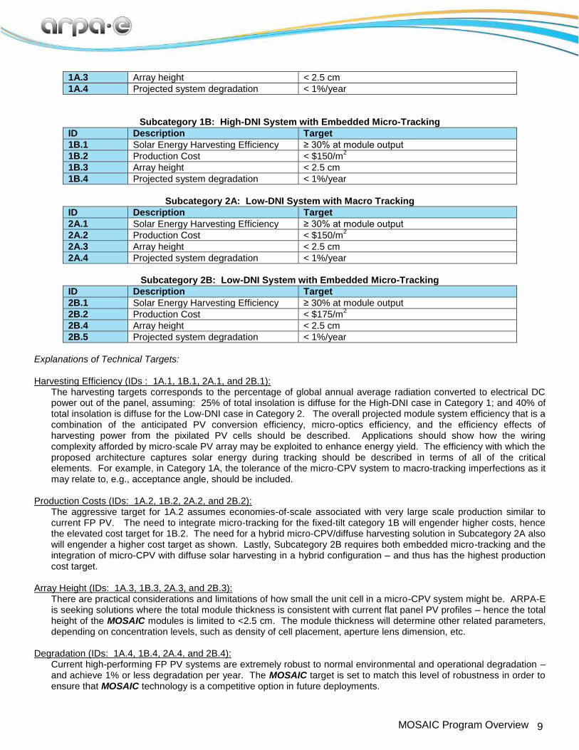
Subcategory 1A: High-DNI System with Macro-Tracking
ID Description Target
1A.1 Solar Energy Harvesting Efficiency ≥ 30% at module output
1A.2 Production Cost < $125/m2
9 MOSAIC Program Overview
1A.3 Array height < 2.5 cm
1A.4 Projected system degradation < 1%/year
Subcategory 1B: High-DNI System with Embedded Micro-Tracking
ID Description Target
1B.1 Solar Energy Harvesting Efficiency ≥ 30% at module output
1B.2 Production Cost < $150/m2
1B.3 Array height < 2.5 cm
1B.4 Projected system degradation < 1%/year
Subcategory 2A: Low-DNI System with Macro Tracking
ID Description Target
2A.1 Solar Energy Harvesting Efficiency ≥ 30% at module output
2A.2 Production Cost < $150/m2
2A.3 Array height < 2.5 cm
2A.4 Projected system degradation < 1%/year
Subcategory 2B: Low-DNI System with Embedded Micro-Tracking
ID Description Target
2B.1 Solar Energy Harvesting Efficiency ≥ 30% at module output
2B.2 Production Cost < $175/m2
2B.4 Array height < 2.5 cm
2B.5 Projected system degradation < 1%/year
Explanations of Technical Targets: Harvesting Efficiency (IDs : 1A.1, 1B.1, 2A.1, and 2B.1): The harvesting targets corresponds to the percentage of global annual average radiation converted to electrical DC
power out of the panel, assuming: 25% of total insolation is diffuse for the High-DNI case in Category 1; and 40% of total insolation is diffuse for the Low-DNI case in Category 2. The overall projected module system efficiency that is a combination of the anticipated PV conversion efficiency, micro-optics efficiency, and the efficiency effects of harvesting power from the pixilated PV cells should be described. Applications should show how the wiring complexity afforded by micro-scale PV array may be exploited to enhance energy yield. The efficiency with which the proposed architecture captures solar energy during tracking should be described in terms of all of the critical elements. For example, in Category 1A, the tolerance of the micro-CPV system to macro-tracking imperfections as it may relate to, e.g., acceptance angle, should be included.
Production Costs (IDs: 1A.2, 1B.2, 2A.2, and 2B.2):
The aggressive target for 1A.2 assumes economies-of-scale associated with very large scale production similar to current FP PV. The need to integrate micro-tracking for the fixed-tilt category 1B will engender higher costs, hence the elevated cost target for 1B.2. The need for a hybrid micro-CPV/diffuse harvesting solution in Subcategory 2A also will engender a higher cost target as shown. Lastly, Subcategory 2B requires both embedded micro-tracking and the integration of micro-CPV with diffuse solar harvesting in a hybrid configuration – and thus has the highest production cost target.
Array Height (IDs: 1A.3, 1B.3, 2A.3, and 2B.3): There are practical considerations and limitations of how small the unit cell in a micro-CPV system might be. ARPA-E is seeking solutions where the total module thickness is consistent with current flat panel PV profiles – hence the total height of the MOSAIC modules is limited to <2.5 cm. The module thickness will determine other related parameters, depending on concentration levels, such as density of cell placement, aperture lens dimension, etc.
Degradation (IDs: 1A.4, 1B.4, 2A.4, and 2B.4): Current high-performing FP PV systems are extremely robust to normal environmental and operational degradation –
and achieve 1% or less degradation per year. The MOSAIC target is set to match this level of robustness in order to ensure that MOSAIC technology is a competitive option in future deployments.

10 MOSAIC Program Overview
F. REQUIRED METRICS AND CALCULATIONS FOR FULL APPLICATIONS
Performance Analysis of Proposed MOSAIC solutions
The MOSAIC program is seeking technical solutions that address either of two distinct outdoor solar illumination conditions: Category 1) High direct normal irradiance (DNI) – defined here as > 75% DNI (25% Diffuse); Category 2) Low DNI – defined here as < 60% DNI (40% Diffuse). For partial solutions that are relevant aspects of the system (for example, optics or PV arrays), the performance should be addressed in the context of an overall system concept. In the
system context, harvesting efficiency (𝜂𝐻𝑎𝑟𝑣𝑒𝑠𝑡,𝐷𝐶 ) is defined as:
𝜂𝐻𝑎𝑟𝑣𝑒𝑠𝑡,𝐷𝐶 = electrical power output / solar power input
for DC power as delivered by the module, previously defined in Section I.B.1. As an example calculation to guide a performance model, we breakdown 𝜂𝐻𝑎𝑟𝑣𝑒𝑠𝑡,𝐷𝐶 into two (2) primary components: Optical efficiency (𝜂𝑜𝑝𝑡 ) and PV cell
efficiency (𝜂𝑃𝑉 ). Additionally, we breakdown the optical and PV cell components into those that are designed for concentrated DNI light - (𝜂𝑜𝑝𝑡,𝐷𝑁𝐼 , 𝜂𝑃𝑉,𝐷𝑁𝐼 ) and those for diffuse radiation (𝜂𝑜𝑝𝑡,𝐷𝐼𝐹𝐹 , 𝜂𝑃𝑉,𝐷𝐼𝐹𝐹). This example excludes all
2nd
-order effects such as cross-over sensitivity of devices to different radiation types, absorption effects in optical
components, multiple reflections, etc. 𝜂𝐻𝑎𝑟𝑣𝑒𝑠𝑡,𝐷𝐶 can be written as
𝜂𝐻𝑎𝑟𝑣𝑒𝑠𝑡,𝐷𝐶 = 𝑓𝐷𝑁𝐼 ∙ 𝑔(𝜃, 𝜙)𝐷𝑁𝐼 ∙ 𝜂𝑜𝑝𝑡,𝐷𝑁𝐼 ∙ 𝜂𝑃𝑉,𝐷𝑁𝐼 ∙ 𝐹𝐷𝑁𝐼 +
(1 − 𝑓𝐷𝑁𝐼) ∙ 𝑔(𝜃, 𝜙)𝐷𝐼𝐹𝐹 ∙ 𝜂𝑜𝑝𝑡,𝐷𝐼𝐹𝐹 ∙ 𝜂𝑃𝑉,𝐷𝐼𝐹𝐹 ∙ 𝐹𝐷𝐼𝐹𝐹
where 𝑓𝐷𝑁𝐼 is the fraction of DNI global insolation, and 𝐹 represents other system factors not related to the PV material or
optics, such as resistance, edge effects, and intensity. For Category 1 and 2 solutions, 𝑓𝐷𝑁𝐼 is 0.75 and 0.60, respectively.
For the case of internal (also referred to as “embedded tracking”, Categories 1B and 2B), 𝑔(𝜃, 𝜙) is a factor that takes into account tracking efficiency and is here defined as the ratio of the harvested energy in the proposed system using internal tracking to the harvested energy when using an external tracking mechanism (i.e., the ability to tilt the entire panel on a given axis).
Not all Full Applications are expected to use the exact same variables and same analytical formulas, however, all Full Applications must provide quantitative estimates of optical efficiency, PV efficiency (which could factor in multi-junctions and/or multiple materials) and provide assumptions about other factors that will affect overall system efficiency. ARPA-E seeks a reasonably detailed justification of at least four major performance factors: 𝜂𝑜𝑝𝑡,𝐷𝐼𝐹𝐹 , 𝜂𝑃𝑉,𝐷𝐼𝐹𝐹 , 𝜂𝑜𝑝𝑡,𝐷𝑁𝐼 , 𝜂𝑃𝑉,𝐷𝑁𝐼.
In the case of solar cell efficiencies, 𝜂𝑃𝑉,𝐷𝑁𝐼 & 𝜂𝑃𝑉,𝐷𝐼𝐹𝐹, the values provided should be representative of the performance
expected under the light intensity anticipated. In the case of optical efficiencies, 𝜂𝑜𝑝𝑡,𝐷𝑁𝐼 & 𝜂𝑜𝑝𝑡,𝐷𝐼𝐹𝐹, values provided must
be estimated and justified quantitatively to account for losses such as absorption, refraction, scattering, diffraction efficiency, and reflectivity. In addition, some qualitative discussion must be considered regarding the practicality of the system regarding ways in which performance can be degraded, such as by debris, partial shading, manufacturing tolerances, PV cell illumination uniformity, and material degradation. All applications that address only categories 1A and 2A can assume 𝑔(𝜃, 𝜙) = 1, which assumes equivalent performance in using conventional tracking methods. All proposed
solutions in categories 1B and 2B must provide an estimate of either 𝑔(𝜃, 𝜙), or another metric that quantifies the effect of
internal tracking on module energy production relative to an external tracking mechanism.
Figure 5 shows a simplified example schematic, followed by Table I.F.1, an example of a spreadsheet that clearly documents known and assumed efficiencies for major system component based on Figure 5. Full applications must provide a similar figure and table. Figure 5 and Table I.F.1 do not include estimates for electrical efficiency after photoelectric conversion in the PV cell, however, applicants are encouraged to include detail and trade-offs on these aspects of the system as well. For partial solutions (Category 3), all applications must make assumptions about the other system elements that are compatible with their proposed solution to calculate a reasonable estimate of how the module and system is expected to perform. Applications in Categories 1 and 2 must provide a calculation of the harvesting efficiency at the following DNI/Diffuse values: Category 1 at 75% DNI / 25% Diffuse and Category 2 at 60% DNI / 40% Diffuse.

11 MOSAIC Program Overview
Figure 5. Simplified, notional schematic for calculating solar harvesting efficiency, considers only primary losses (not secondary reflections, for example). 𝐼0 : Incident intensity, 𝐼1 : Intensity propagating toward PV cell after first optical
element, in this schematic 𝑇0,1 is the transmission coefficient for the first optical element and represents the ratio of the
light that would reach the PV cell (in absence of subsequent interfaces) to the total incident light on that element. In this schematic, the overall optical efficiency is equal to the product of all transmission coefficients. Applicants do not need to use the exact notation used here, however, this provides an example of the type of minimalist model that must be described.
Table I.F.1. Example component efficiencies of a notional system for a Category 1 solution with concentrating PV solution only
Parameter Symbol Value Estimated variation*
Fractional DNI 𝑓𝐷𝑁𝐼 .75
Optical efficiency 𝜂𝑜𝑝𝑡 .93 0.05
PV efficiency 𝜂𝑃𝑉 0.44 0.05
Other system efficiency 𝐹 0.98 0.05
Solar Harvesting Efficiency 𝜂𝐻𝑎𝑟𝑣𝑒𝑠𝑡,𝐷𝐶 0.30 0.026
*where possible, estimate and justify variation due to system components and designs.
Cost modeling of Proposed MOSAIC solutions
In order to practically evaluate the projected cost of the proposed system, applicants must include a simple calculation and justification of the values used, as well as any sources of uncertainty (whether qualitative or quantitative). At minimum, a projected bill of materials (BOM) must be supplied, along with rationale for projected costs, the associated volumes required to create the proposed system (or sub-system component), and estimates for manufacturing and assembly costs with references. Table I.F.2 shows an example of a simple calculation.

12 MOSAIC Program Overview
Table I.F.2. Notional system with two optical materials and one PV material
System element Fraction of module area $/m2
$/m2
module integrated
Optics 1 0.95 29 28
Optics 2 0.95 19 18.30
PV cell 1 0.01 (100x) 5,000 50
PV cell 2 - - -
Other material 1 - 2.50 2.50
Other material 2 - - -
Total system BOM - - $98.80
Assembly markup - - 1.5x
Manufactured cost (current estimate)
- - $148.20
The above tables and figure show examples of the type of analysis expected in order to justify each claim. Each Full Application may require different variables and methods of analysis; however, any claims regarding performance or cost must be quantified with a justification for each value used in the calculation.
G. APPLICATIONS SPECIFICALLY NOT OF INTEREST
The following types of applications will be deemed nonresponsive and will not be reviewed or considered (see Section III.C.2 of the FOA):
Applications that fall outside the technical parameters specified in Section I.E of the FOA Applications that have been submitted in response to other currently issued ARPA-E FOAs. Applications that are not scientifically distinct from applications submitted in response to other currently issued
ARPA-E FOAs. Applications for basic research aimed solely at discovery and/or fundamental knowledge generation. Applications for large-scale demonstration projects of existing technologies. Applications for proposed technologies that represent incremental improvements to existing technologies. Applications for proposed technologies that are not based on sound scientific principles (e.g., violates a law of
thermodynamics). Applications for proposed technologies that are not transformational, as described in Section I.A of the FOA and
as illustrated in Figure 1 in Section I.A of the FOA. Applications for proposed technologies that do not have the potential to become disruptive in nature, as described
in Section I.A of the FOA. Technologies must be scalable such that they could be disruptive with sufficient technical progress (see Figure 1 in Section I.A of the FOA).
Applications that are not scientifically distinct from existing funded activities supported elsewhere, including within the Department of Energy.
Applications that propose the following: non-PV solutions (e.g., concentrated solar thermal or thermal-electric solutions), 1-sun (non-concentrated) solutions. PV to be deployed in space, or on balloons or towers.