morse: model-based real-time systems engineering … · –physics-based predictive models for the...
TRANSCRIPT

Copyright © Claytex Services Limited 2017
Mike Dempsey
Claytex
Future Powertrain Conference 2017
MORSE: MOdel-based Real-time Systems
Engineering
Reducing physical testing in the calibration of
diagnostic and driveabilty features

Copyright © Claytex Services Limited 2017
MORSE project
• MOdel-based Real-time Systems Engineering (MORSE)
– Collaborative research project with Ford and AVL
Powertrain
– Co-funded by Innovate UK as part of the “Towards zero
prototyping” competition
• UK government organisation
– 2 year project
• The project aim was to address some of the challenges
of validating the functional requirements of electronic
control systems using real-time simulation of multi-
domain physical models created in Dymola

Copyright © Claytex Services Limited 2017
MORSE – Development activities
• Library development
– Physics-based predictive models for the engine,
transmission and driveline
– Combustion models, airpath models, thermodynamics and
mechanics
• Driveability calibration
– Virtual development process coupled to optimisation
tools
• OBD validation
– HiL based validation of real controllers using the
physics based plant models

Copyright © Claytex Services Limited 2017
Transmission model enhancements
• Predictive temperature-
dependent drag and friction
loss models
• Allows the investigation of
warm up and performance
predictions:
– Launch performance
– Fuel consumption and
emissions
– Thermal management

Copyright © Claytex Services Limited 2017
Detailed gear set model reduction
• A model reduction method was developed for the
Powertrain Dynamics library
• Starting from a detailed transmission model (above
diagram), the model reduction function lumps the
individual component inertias and losses for each gear
for a range of speed-load points
• Yields 30 – 60% saving in CPU time depending on
transmission complexity
Lumped
inertia
Lumped
losses
Variable
ratio

Copyright © Claytex Services Limited 2017
Predictive Combustion Model
• A 0D predictive combustion model was developed for the Engines library
• A parameter sensitivity analysis returned the parameters which had most influence on
the predicted burn rate:
– Flame centre
– Initialization of flame kernel radius and mass
– Expansion factor of turbulent flame speed
• Calibration of all the model parameters was based on part load and full load test data
provided by Ford
• The model was then validated post calibration against a further set of part and full load
operating points

Copyright © Claytex Services Limited 2017
Predictive Combustion Model Reduction
• Model reduction process diagram for Wiebe coefficient derivation from predicted burn rate
MFB: Mass Fraction Burnt
EOC: End Of Combustion
Optimisation of
Wiebe
coefficients via
VisualDOC
Predicted MFB
Derived Wiebe coefficients
f(rpm,load,afr,timing)
Error
Minimization

Copyright © Claytex Services Limited 2017
Parameterised Split Engine Model validation
• The Simulink split engine model subsystems
(air paths, mechanics & combustion models)
were compiled from the Dymola physical
models
• The combustion models incorporate the
Wiebe coefficients derived from the
predictive combustion models.
• Validation shows +/-4% accuracy trend
across speed range
CylindersMechanics
Air-paths
Copyright © Claytex Services Limited 2017
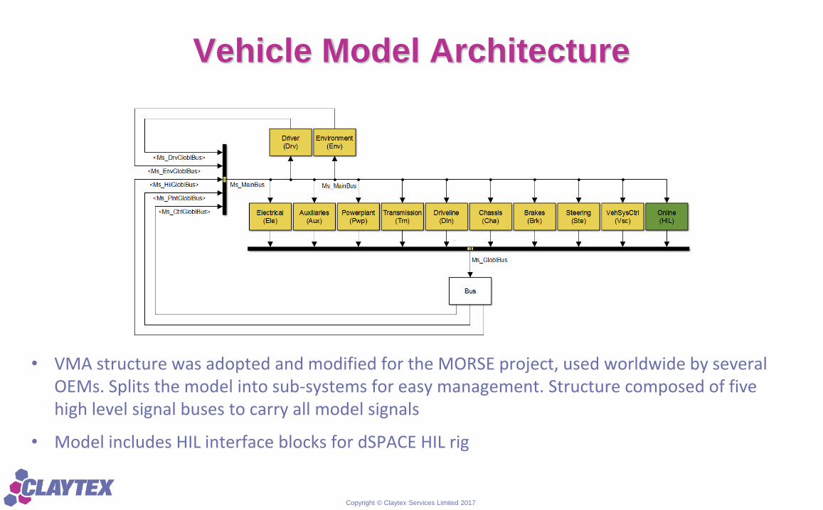
Vehicle Model Architecture
• VMA structure was adopted and modified for the MORSE project, used worldwide by several OEMs. Splits the model into sub-systems for easy management. Structure composed of five high level signal buses to carry all model signals
• Model includes HIL interface blocks for dSPACE HIL rig

Copyright © Claytex Services Limited 2017
Single & Multicore Architecture
• The single core
architecture requires
minor changes, only
adding some dSPACE
blocks when moving to
multi core
• This means model
structure and signal
structure is maintained
between the two
models
• The model can be
developed for single
core and SIL
applications and
converted to multicore
for HIL applications
Single-core implementation
Multi-core implementation

Copyright © Claytex Services Limited 2017
Vehicle model validation vs. test data
• Several manoeuvres tested in Dunton with a
family car equipped with AVL-DRIVE
sensors and unit
• The goal was to collect required data used to
tune the relevant Dymola vehicle model
parameters
• The comparison of Engine Speed and
Vehicle Acceleration in terms of frequency
and amplitude of oscillations during tip-in/tip-
out, as well as the coast-down curve, is in
agreement with the measured data

Copyright © Claytex Services Limited 2017
AVIDO (Automated Virtual Driveability
OptimizationAutomated MATLAB routine to:
• Communicate with calibration
software ATI Vision
• Run the SIL test of the model
(controller, driver, Dymola vehicle)
• Call AVL DRIVE and import test
recorded data to generate the
objective driveability ratings
• Optimize driveability ratings and
update the set of test parameters
for the next iteration
Test definition
START
END
PCM online
Initial calibration
Run automatic
manoeuvre test
Data recording
during test
AVL DRIVE
OptimizationCalibration change
User
criteria
met?
PCM offline
User’s manual
steps
Yes
No

Copyright © Claytex Services Limited 2017
Calibration Validation with AVL-AVIDO
• Tip-in test at 50% accelerator in 1st gear or at
100% accelerator in 2nd gear
• 2 parameters are investigated from the TipIn and
AntiShuffle functions
• The Response Surfaces from a “sweep test”
show the higher Driver Rating around the Ford
base values (red square)
• The density of design from an optimization test
show convergence in the same area
• Results confirmed that the existing calibration is
the optimal one

Copyright © Claytex Services Limited 2017
Further work
• Use of the split engine model within a HiL environment to test:
– Real time capability of:
• Crank Angle Resolved Engine Models
• Vehicle transmission and driveline models with increased levels of compliance and lash
– OBD, sensor and actuator fault testing using physical models
• Inclusion of developed capability within Engines and Powertrain Dynamics libraries

Copyright © Claytex Services Limited 2017
Conclusions
• Integration of predictive combustion model into Engines library
• Enhancement of Powertrain Dynamics library with increased fidelity and predictive
capabilities of thermal models
• Model reduction techniques have been developed to allow users to efficiently reduce
the computational effort without manual rearrangement of the models
• Driveability calibration optimisation for tip-in manoeuvres using SIL model successfully
completed
• New SIL and HIL multi-core architectures developed to maximise use of multiple cores