morphological synthesis and workspace design for a
TRANSCRIPT
© The author; licensee Universidad Nacional de Colombia. Revista DYNA, 87(213), pp. 129-139, April - June, 2020
DOI: http://doi.org/10.15446/dyna.v87n213.80676
Morphological Synthesis and workspace design for a parallel manipulator with linear actuators •
Carlos Andrés Mesa-Montoya, Héctor Fabio Quintero-Riaza & Federico Gutiérrez-Madrid
Facultad de Ingeniería Mecánica, Universidad Tecnológica de Pereira, Pereira, Colombia. [email protected], [email protected],
Received: July 4th, 2019. Received in revised form: March 17th, 2020. Accepted: March 30th, 2020.
Abstract This paper addresses the kinematic structure and workspace analysis of a parallel manipulator with linear actuators considering two studies. The first one was based on a morphological synthesis in which a kinematic connections approach was implemented. The set of combinations of joints and links for the desired system and their linkage are illustrated. Finally, the development regarding the conceivable morphology is detailed, providing three linear degrees of freedom between the mobile and fixed platforms. The second study presented the dimensional synthesis of the manipulator, considering a workspace required and an input transmission index. The geometrical design was based on the maximum inscribed workspace volume; the cylindrical shape radius inscribed on a workspace intersection is also exemplified. The geometric determination of the workspace for the manipulator was demonstrated using computer-aided design. A design result of the Delta as checked with the stiffness and condition indices. Keywords: dimensional synthesis; kinematics design; morphological synthesis; parallel manipulator; workspace.
Síntesis morfológica y dimensional de un manipulador paralelo con actuadores lineales
Resumen Este artículo aborda el análisis cinemático y el espacio de trabajo de un manipulador paralelo con actuadores lineales considerando dos estudios. El primero trata sobre la síntesis morfológica, implementando un acercamiento por medio del método de juntas cinemáticas. Son ilustrados el conjunto de combinaciones de las juntas y pares para el sistema deseado y sus relaciones. Finalmente, se detalla el desarrollo de la morfología concebida, la cual provee tres grados de libertad lineales entre la plataforma fija y móvil. El segundo estudio presenta la síntesis dimensional del manipulador, considerando un espacio de trabajo requerido y un índice de trasmisión de entrada. El diseño geométrico utiliza el máximo volumen de trabajo inscrito; se muestra la geometría cilíndrica inscrita en la intersección con espacio de trabajo. Se determina la geometría del espacio de trabajo utilizando CAD y el diseño resultante del Delta es verificado con el índice de rigidez y de condición. Palabras clave: diseño cinemático; espacio de trabajo; manipulador paralelo; síntesis dimensional; síntesis morfológica.
1. Introduction A large variety of architectures exist in the family of
robots, the most popular ones in the industry being parallel and serial manipulators. In serial manipulators, the actuators are located along their mechanical structure, generating an increase in the inertia that the robot must overcome to move; this means that the more actuators the robot has, the higher
How to cite: Mesa-Montoya, C.A, Quintero-Riaza, H.F, and Gutiérrez-Madrid, F. Morphological Synthesis and Workspace Design for a Parallel Manipulator with Linear Actuators. DYNA, 87(213), pp. 129-139, April - June, 2020.
the charge on it is, affecting the stability of the entire mechanism. Additionally, each actuator increases the probability of generating an error of position and orientation of the terminal tool coupled to the mobile platform [1].
For this reason, parallel manipulators emerged, in which two or more kinematic chains support the mobile platform, increasing its stiffness, stability, load capacity and precision of position, orientation, velocity and acceleration of the final

Mesa-Montoya et al / Revista DYNA, 87(213), pp. 129-139, April - June, 2020.
130
actuator, and the entire robot [2]. These advantages make these robots adequate for applications such as a) machining processes, b) mounting, c) manipulation, d) transport and e) storage [3].
Because of the importance of these robots, this paper addresses the kinematic, structural, and workspace analysis of a manipulator with linear actuators with consideration to two studies.
The first study examined the morphological synthesis of diverse solutions for kinematic chain structures for parallel manipulators of low mobility. This has been the focus of much research over the last few decades, resulting in four frequently used methods for morphological synthesis today: a) the screw theory [7], b) theory of displacement groups [8-10], c) theory of lineal transformations [11-13], and d) kinematic connections [1,14]. In this paper, the method of kinematic connections is used through the methodology proposed by Zhang [1]. Subsequently, the Chebychev-Grübler-Kutzbach criterion is introduced. The set of combinations of joints and links for the desired system and their linkage, omitting geometric details such as the link length and distribution, are illustrated. Finally, the development regarding the conceivable morphology is detailed, providing three linear degrees of freedom between the mobile and fixed platforms.
The second study examined the dimensional synthesis of the selected manipulator. To satisfy the demands for the design of these manipulators, the academic community has conducted various research that aims to establish methods involving numeric techniques of optimization [21,22], performance maps [23,24], and a maximum inscribed workspace [17], to guarantee a workspace that is as regular as possible. For the development of this study, the method of maximum inscribed workspace proposed by Lui [17] was used, incorporating an input transmission index [16]. Additionally, the cylindrical shape radius inscribed on the workspace intersection was exemplified. The geometric determination of the workspace for the manipulator was demonstrated using computer-aided design (CAD). 2. Methods 2.1. Preliminary restrictions of the manipulator
The border conditions or dimensional restrictions of the manipulator are the results of the settling of the workspace conditions, where the manipulator demonstrates its greater ability, and which have a low possibility of manifesting singular positions on its mobile elements. Table 1 shows the maximum permissible restrictions for the components of the manipulator, and the workspace dimensions according to the technical specifications of parallel manipulators of similar architecture that are used for commercial purposes [4,5]. 2.2. Morphological synthesis
Table 2 shows the synthesis method of kinematic connections proposed by Zhang [1] for full isotropic parallel manipulators.
Table 1. Structural requirements. Characteristics Preliminary Restrictions Restrictions
Structural
Fixed platform radius 310-500 mm Leg length 150-300 mm Forearm length 290-500 mm Mobile platform radius 50-300 mm
Workspace
Maximum cross-sectional dimension (cylindrical shape)
150-265 mm
Maximum cross-sectional dimension (cuboid) 106-187 mm
Maximum Z Height 235-400 mm Source: The Authors. Table 2. Synthesis methodology of full-isotropic parallel manipulators.
Stage Objectives Activities
1 Establishing
possible structures
Alternatives for the kinematic chain.
Structure of the vertexes of connection.
Structures for the mobile and fixed platforms.
2
Construction of architectures
To scheme possible architectures for the manipulator.
3
Selection of the most promising architecture
To consider the number and type of degrees of freedom in the kinematic joints.
To look for practicality and simplicity.
To eliminate kinematic joints of the prismatic type that may generate passive conditions.
To eliminate the rotation along the perpendicular axis to the plane of the fixed platform.
To look for symmetric structures. Source: The Authors. 2.2.1. Design criteria
The structural conditions considered in the synthesis
process are the following: a) manipulator with three degrees of freedom, b) fully-isotropic parallel manipulator, c) two known elements (fixed and mobile platform), and d) three parallel kinematic chains.
To determine the possible degrees of freedom provided by each kinematic chain in the manipulator, we evaluated the mobility of the kinematic chain using the Chebychev-Grübler-Kutzbach formula [15], along with the contribution of Tsai [15] to the passive degrees of freedom:
𝑀𝑀 = 𝑑𝑑(𝑛𝑛 − 𝑔𝑔 − 1) + �𝑓𝑓𝑖𝑖 − 𝑓𝑓g
𝑔𝑔
𝑖𝑖=1
(1)
where M is the degrees of freedom of the kinematic chain;
𝑑𝑑 is the degrees of freedom of the individual elements without restricting (6 in the spatial scenario and 3 in the plane scenario); n is the number of rigid bodies, elements, or links of the kinematic chain; g is the number of joints; 𝑓𝑓𝑖𝑖 is the

Mesa-Montoya et al / Revista DYNA, 87(213), pp. 129-139, April - June, 2020.
131
number of degrees of freedom per kinematic pair; and 𝑓𝑓g is the number of passive degrees of freedom in the kinematic chain, and it may take positive values when degrees of freedom are available (not transferred to the terminal element) or negative values when there are additional restrictions to the movement.
2.2.2. Distribution of degrees of freedom per kinematic chain.
The different configurations of elements and joints that
consolidate the kinematic chain can be determined by considering the different assumptions established to each of the parameters of Eq. (1). First, the equations that enable determining the number of elements in the kinematic chain, in function of the joints are defined:
𝑛𝑛 = 2 + 𝑛𝑛𝑐𝑐𝑐𝑐 (2)
𝑛𝑛cc
⎩⎪⎨
⎪⎧��𝑓𝑓𝑙𝑙𝑙𝑙 − 1�
𝐿𝐿
𝑙𝑙=1
Binary
�(𝑓𝑓𝑙𝑙𝑙𝑙 − 2)𝐿𝐿
𝑙𝑙=1
Ternary
(3)
where n is the number of elements that consolidate the
parallel manipulator, 2 represents the two platforms (fixed and mobile), and 𝑛𝑛𝑐𝑐𝑐𝑐 is the set of elements that consolidate the parallel kinematic chains, which can be calculated in two different ways: a) Considering each element as binary regarding the number
of joints, b) Considering that at least one element per kinematic chain
is ternary. The total number of joints in the manipulator can be
expressed as follows:
𝑔𝑔 = �𝑓𝑓𝑙𝑙
𝐿𝐿
𝑙𝑙=1
(4)
Substituting Eqs. (2)-(4) into (1) results in M for the
scenario of binary elements (5) and ternaries (6):
𝑀𝑀 = 6[1 − 𝐿𝐿] + �𝑓𝑓𝑙𝑙𝑙𝑙 − 𝑓𝑓𝑔𝑔
𝑔𝑔
𝑙𝑙=1
(5)
𝑀𝑀 = 6[1 − 2𝐿𝐿] + �𝑓𝑓𝑙𝑙𝑙𝑙 − 𝑓𝑓𝑔𝑔
𝑔𝑔
𝑙𝑙=1
(6)
By knowing the values of M, L, and fg, the total degrees
of freedom provided by the joints in the kinematic chains that consolidate the manipulator can be determined.
2.3. Dimensional synthesis The purpose of the dimensional synthesis is to determine
the primary dimensions (or additional parameters) and initial position of a preconceive mechanism, according to the tasks that are developed. The term “primary dimensions” refers to the lengths of the links, whether they are binary or ternary. The defined dimensional parameters must generate a maximum workspace that accomplishes the following requirements [16]: a) regular form of the workspace according to the application, b) adequate required skill, c) compact configuration, and d) low-cost. Considering the criterion previously defined, the method of maximum inscribed workspace is used [17], incorporating an input transmission index [16].
2.3.1. Input transmission index
The function of the manipulator is to transmit the
movement and force of an input link towards an exit link, guaranteeing the transmitted force along the kinematic chains, until the stated element can generate the dynamic equilibrium. Considering that the architecture of the manipulator is completely parallel and only considers one actuator per kinematic chain (considering active prismatic joints, but not the gravitational effects and the friction in the joints), the input transmission index is defined by [16]:
𝜆𝜆𝑖𝑖 = |𝑓𝑓𝑖𝑖 ∙ 𝑣𝑣𝑖𝑖| = |cos𝜓𝜓| = |sin𝛾𝛾| (7)
where 𝜆𝜆𝑖𝑖 is the input transmission index, 𝛾𝛾 is the angle of
transmission, 𝜓𝜓 is the angle of deviation, 𝑓𝑓𝑖𝑖 is the static force, and 𝑣𝑣𝑖𝑖 is the absolute velocity vector.
Fig. 1 shows the inverse transmission and deviation angles, as well as the static force of the coupler:
a) Inverse transmission angle b) Inverse deviation angle
Figure 1. Inverse transmission and deviation angles Source: The Authors.
Mesa-Montoya et al / Revista DYNA, 87(213), pp. 129-139, April - June, 2020.
132
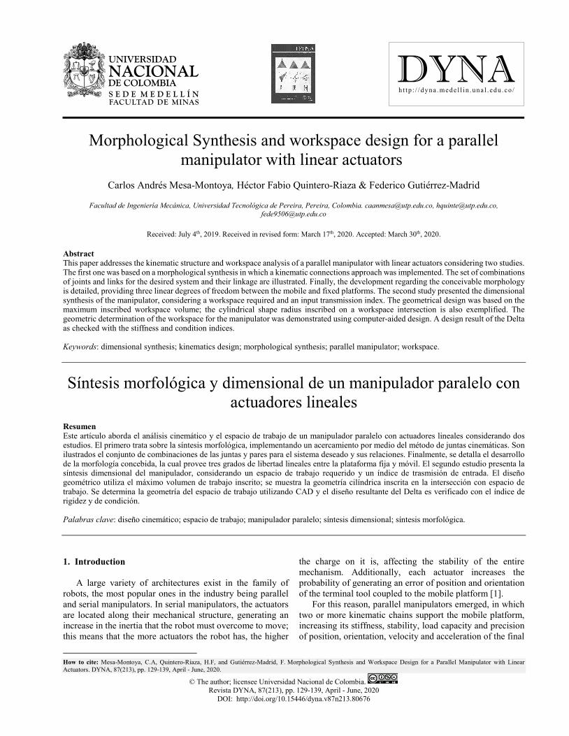
The angles 𝛾𝛾 and 𝜓𝜓, in Fig. 1 correspond to two criteria of the manipulator’s input manipulability. The first angle is known as the transmission angle, 𝛾𝛾, and is defined as the lower angle between the relative velocity vector, vC/E, of the coupler element, and the absolute velocity vector, vC, of the input link, both obtained from the kinematic pair, C (Fig. 1 (a)). The other criterion consists of using the direction of the static force transmitted, F3/2, from the coupler to the input element and the velocity of the connection point, vC;, the angle between them is known as deviation angle, 𝜓𝜓. In the analysed manipulator, the transmission and deviations angles are complementary (Fig. 1 (b)).
According to Tao [18], for systems in which the transmission of movement must be precise and at a high speed, the permissible values for the angle of transmission must be between 45 and 135o. Sharma [19] postulated that an angle of transmission lower than 20° is unacceptable for a mechanism of high velocity. Martin [20] asserted that mechanisms of general purpose must comply with a minimum angle of transmission higher than 40°. For the configuration studied in this project, the angle of transmission could not attain higher values than 90°; otherwise, the mobile platform would have surpassed the plane where the prismatic joints were located, which was not structurally possible to achieve. Taking as reference the previously mentioned, the input transmission index must not be lower than sin 45𝑜𝑜 ≈ 0,7. According to Liu [16] when the input transmission index is higher or equal to 0.7, the manipulator possesses an adequate relation of mobility or force. If within the maximum inscribed workspace, the positions of the kinematic chains of the manipulator are guaranteed, values lower to 0.7 will not be presented in the input transmission index, the mobile platform of the manipulator will have an adequate capacity to transmit movement and force, with a low possibility, and singular positions may result [16].
2.3.2. Design criteria
To determine the parameters, the method considers a
cylindrical workspace of radius r0 and height h. From the cylindrical form obtained, an inscribed hexahedron of a similar form can also be defined. In Fig. 2 the mobile platform is considered to move over the horizontal plane with z=z0 measured in regard to the framework of reference (OXYZ).
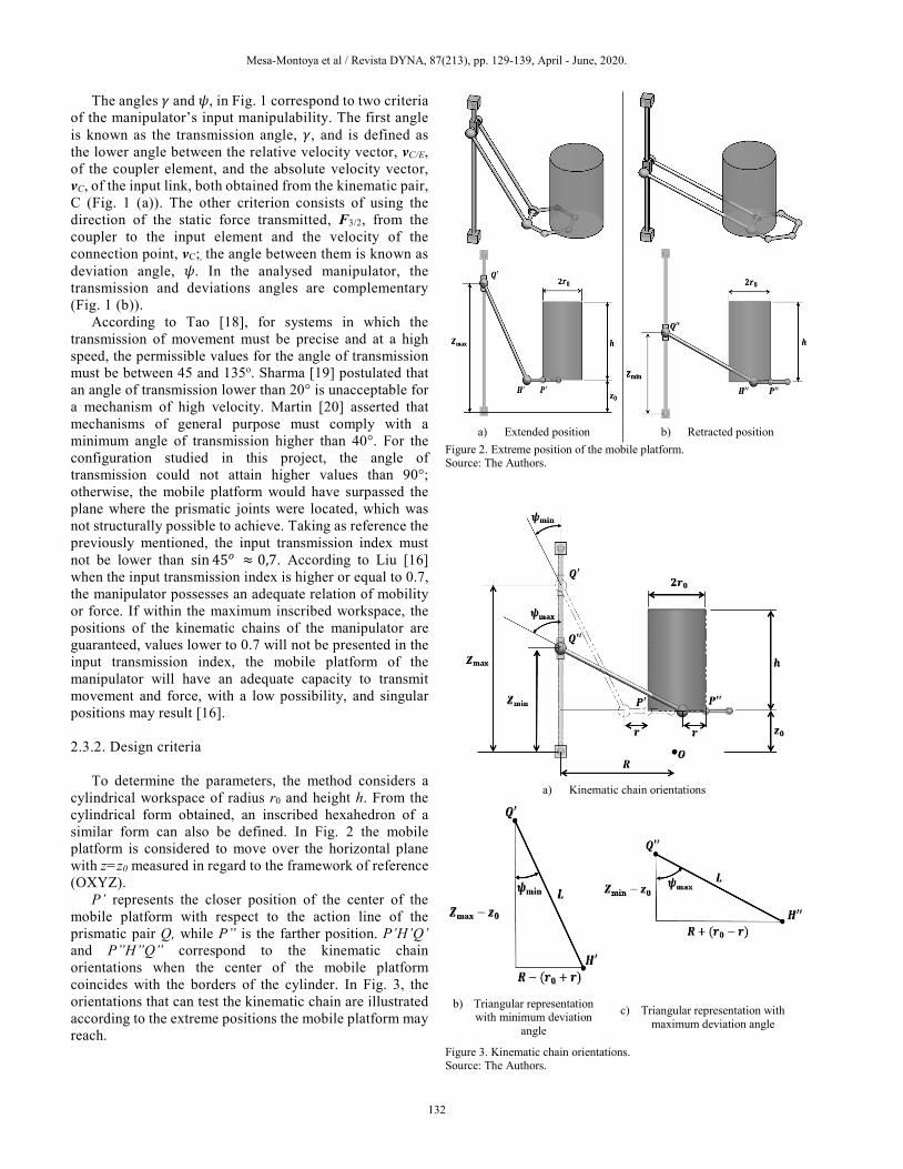
P’ represents the closer position of the center of the mobile platform with respect to the action line of the prismatic pair Q, while P” is the farther position. P’H’Q’ and P”H”Q” correspond to the kinematic chain orientations when the center of the mobile platform coincides with the borders of the cylinder. In Fig. 3, the orientations that can test the kinematic chain are illustrated according to the extreme positions the mobile platform may reach.
a) Extended position b) Retracted position
Figure 2. Extreme position of the mobile platform. Source: The Authors.
a) Kinematic chain orientations
b) Triangular representation with minimum deviation
angle
c) Triangular representation with maximum deviation angle
Figure 3. Kinematic chain orientations. Source: The Authors.

Mesa-Montoya et al / Revista DYNA, 87(213), pp. 129-139, April - June, 2020.
133
From Figs. 3 (b) and (c) the following relations are obtained between the dimensional parameters of the manipulator:
sin𝜓𝜓max =𝑅𝑅 + (𝑟𝑟0 − 𝑟𝑟)
𝐿𝐿 (8)
sin𝜓𝜓min =𝑅𝑅 − (𝑟𝑟0 + 𝑟𝑟)
𝐿𝐿 (9)
With the aim of establishing a technical condition and
structural reliability between the maximum and minimum deviation angles, these are related to the maximum opening angle (in practical terms, the spherical joints have a permissible interval of values for the opening angle between 15 and 30°) that enables the spherical joint Ci, of the form
𝜌𝜌 = 𝜓𝜓max − 𝜓𝜓min (10)
If the deviation angles are specified, the dimensional
parameters L and R-r can be determined, using Eq. (9) and (10), in the form
𝐿𝐿 =2𝑟𝑟0
sin𝜓𝜓max − sin𝜓𝜓min (11)
𝑅𝑅 − 𝑟𝑟 = 𝐿𝐿 ∙ sin𝜓𝜓min + 𝑟𝑟0 (12)
Under the same considerations, in Figs. 3 (b) and (c), the
range of movement can be determined in the prismatic joints, and it corresponds to the defined height for the manipulator’s workspace through the equations.
𝑧𝑧min − 𝑧𝑧0 = 𝐿𝐿 ∙ cos𝜓𝜓max (13)
𝑧𝑧𝑚𝑚𝑚𝑚𝑚𝑚 − 𝑧𝑧0 = 𝐿𝐿 ∙ cos𝜓𝜓min + ℎ (14)
2.4. Jacobian analysis of the manipulator
The Jacobian matrix of a parallel manipulator relates the
velocity of the moving platform (𝑢𝑢 ̇ , 𝑣𝑣 ̇ ,𝑤𝑤 ̇ ) and velocity present in the active kinematic pairs (�̇�𝑞A, �̇�𝑞B, �̇�𝑞C) [1]. The analysis of the Jacobian matrix is used to determine the manipulator’s stiffness matrix, which represents the resistance of the manipulator to the external forces applied to the mobile platform, assuming that the elements or links are rigid. Similarly, it represents the mechanical advantage of the manipulator associated with the capacity to transfer the forces from the linear actuators to the mobile platform [25]. Furthermore, the condition number (which is a measure of the sensitivity of the solution of a reversible matrix to the changes that its components can undergo) of the Jacobian matrix can be used to determine the manipulator's dexterity, which is an important kinematic factor that affects the accuracy of the speed and the dead load of the mobile platform [25,32].
�̇�𝑥 ∙ (𝑥𝑥 − 𝑥𝑥𝑆𝑆𝑖𝑖) + �̇�𝑦 ∙ (𝑦𝑦 − 𝑦𝑦𝑆𝑆𝑖𝑖) + �̇�𝑧 ∙ (𝑧𝑧 − 𝑧𝑧𝑆𝑆𝑖𝑖) − 𝑧𝑧𝑆𝑆𝑆𝑆̇∙ (𝑧𝑧 − 𝑧𝑧𝑆𝑆𝑖𝑖) = 0 (15)
If (𝑧𝑧𝑆𝑆𝑆𝑆, 𝑧𝑧𝑆𝑆𝑆𝑆 , 𝑧𝑧𝑆𝑆𝑆𝑆) = (𝑞𝑞𝑆𝑆, 𝑞𝑞𝑆𝑆, 𝑞𝑞𝑆𝑆) and (x, y, z) = (u, v, w),
then
�̇�𝑢 ∙ (𝑢𝑢 − 𝑥𝑥𝑆𝑆𝑖𝑖) + �̇�𝑣 ∙ (𝑣𝑣 − 𝑦𝑦𝑆𝑆𝑖𝑖) + �̇�𝑤 ∙ (𝑤𝑤 − 𝑞𝑞𝑖𝑖) − 𝑞𝑞�̇�𝑆∙ (𝑤𝑤 − 𝑞𝑞𝑖𝑖) = 0 (16)
Expanding Eqs. (15) and (16) for the three vector loops,
we obtain
�𝑢𝑢 − 𝑥𝑥𝑆𝑆𝑆𝑆 𝑣𝑣 − 𝑦𝑦𝑆𝑆𝑆𝑆 𝑤𝑤 − 𝑞𝑞𝑆𝑆𝑢𝑢 − 𝑥𝑥𝑆𝑆𝑆𝑆 𝑣𝑣 − 𝑦𝑦𝑆𝑆𝑆𝑆 𝑤𝑤 − 𝑞𝑞𝑆𝑆𝑢𝑢 − 𝑥𝑥𝑆𝑆𝑆𝑆 𝑣𝑣 − 𝑦𝑦𝑆𝑆𝑆𝑆 𝑤𝑤 − 𝑞𝑞𝑆𝑆
� �𝑢𝑢 ̇𝑣𝑣 ̇𝑤𝑤 ̇�
= �𝑤𝑤 − 𝑞𝑞𝑆𝑆 0 0
0 𝑤𝑤 − 𝑞𝑞𝑆𝑆 00 0 𝑤𝑤 − 𝑞𝑞𝑆𝑆
� �𝑞𝑞𝑆𝑆 ̇𝑞𝑞𝑆𝑆 ̇𝑞𝑞𝑆𝑆 ̇
�
(17)
In which
�𝐽𝐽𝑞𝑞� = �𝑤𝑤 − 𝑞𝑞𝑆𝑆 0 0
0 𝑤𝑤 − 𝑞𝑞𝑆𝑆 00 0 𝑤𝑤 − 𝑞𝑞𝑆𝑆
� (18)
[𝐽𝐽𝑚𝑚] = �𝑢𝑢 − 𝑥𝑥𝑆𝑆𝑆𝑆 𝑣𝑣 − 𝑦𝑦𝑆𝑆𝑆𝑆 𝑤𝑤 − 𝑞𝑞𝑆𝑆𝑢𝑢 − 𝑥𝑥𝑆𝑆𝑆𝑆 𝑣𝑣 − 𝑦𝑦𝑆𝑆𝑆𝑆 𝑤𝑤 − 𝑞𝑞𝑆𝑆𝑢𝑢 − 𝑥𝑥𝑆𝑆𝑆𝑆 𝑣𝑣 − 𝑦𝑦𝑆𝑆𝑆𝑆 𝑤𝑤 − 𝑞𝑞𝑆𝑆
� = ��𝑃𝑃 − 𝑆𝑆𝑆𝑆𝑆𝑆���������������⃗ ��𝑃𝑃 − 𝑆𝑆𝑆𝑆𝑆𝑆���������������⃗ �(𝑃𝑃 − 𝑆𝑆𝑆𝑆𝑆𝑆)�������������������⃗
� (19)
The Jacobian matrix can be expressed as
𝑱𝑱 =
⎣⎢⎢⎢⎢⎢⎡(𝑢𝑢 − 𝑥𝑥𝑆𝑆𝑆𝑆)𝑤𝑤 − 𝑞𝑞𝑆𝑆
(𝑣𝑣 − 𝑦𝑦𝑆𝑆𝑆𝑆)𝑤𝑤 − 𝑞𝑞𝑆𝑆
1
(𝑢𝑢 − 𝑥𝑥𝑆𝑆𝑆𝑆)𝑤𝑤 − 𝑞𝑞𝑆𝑆
(𝑣𝑣 − 𝑦𝑦𝑆𝑆𝑆𝑆)𝑤𝑤 − 𝑞𝑞𝑆𝑆
1
(𝑢𝑢 − 𝑥𝑥𝑆𝑆𝑆𝑆)𝑤𝑤 − 𝑞𝑞𝑆𝑆
(𝑣𝑣 − 𝑦𝑦𝑆𝑆𝑆𝑆)𝑤𝑤 − 𝑞𝑞𝑆𝑆
1⎦⎥⎥⎥⎥⎥⎤
(20)
In which
(𝑥𝑥𝑆𝑆𝑆𝑆, 𝑦𝑦𝑆𝑆𝑆𝑆) = (0,𝐿𝐿𝑅𝑅𝑅𝑅 ) (𝑥𝑥𝑆𝑆𝑆𝑆,𝑦𝑦𝑆𝑆𝑆𝑆) = �√32𝐿𝐿𝑅𝑅𝑅𝑅 ,−
12𝐿𝐿𝑅𝑅𝑅𝑅�
(𝑥𝑥𝑆𝑆𝑆𝑆 ,𝑦𝑦𝑆𝑆𝑆𝑆) = �−√32𝐿𝐿𝑅𝑅𝑅𝑅 ,−
12𝐿𝐿𝑅𝑅𝑅𝑅 �
2.4.1. Manipulator’s stiffness matrix
Let 𝝉𝝉 = [𝜏𝜏1, 𝜏𝜏2, 𝜏𝜏3,⋯ , 𝜏𝜏𝑛𝑛]𝑇𝑇 be the vector of motor forces
or torques that act on the manipulator and ∆𝒒𝒒 =

Mesa-Montoya et al / Revista DYNA, 87(213), pp. 129-139, April - June, 2020.
134
[∆𝑞𝑞1,∆𝑞𝑞2,∆𝑞𝑞3,⋯ ,∆𝑞𝑞𝑛𝑛]𝑇𝑇 the vector of joint displacements. According to Tsai [15], the vectors 𝝉𝝉 and ∆𝒒𝒒 can be related by the equation
𝜏𝜏 = 𝜒𝜒∆𝑞𝑞 (21)
In which 𝜒𝜒 = diag[𝑘𝑘1, 𝑘𝑘2, 𝑘𝑘3,⋯ , 𝑘𝑘𝑛𝑛, ] is a diagonal n×n
matrix of the stiffness coefficients for each of the kinematic chains.
The resultant force of the mobile platform is related to the vector of motor forces or torques that act on the manipulator following the equation
𝐹𝐹 = 𝐽𝐽t𝜏𝜏 (22)
In which 𝐽𝐽t, is the transposed Jacobian matrix. Joint displacements are related to linear and angular
displacements (∆𝑥𝑥 = [∆𝑥𝑥,∆𝑦𝑦,∆𝑧𝑧,∆𝜙𝜙,∆𝜃𝜃,∆𝜓𝜓]𝑇𝑇) of the mobile platform following the Jacobian Matrix [15], as:
∆𝑞𝑞 = 𝐽𝐽∆𝑥𝑥 (23)
Substituting Eqs. (21) and (23) into (22) we obtain
𝐹𝐹 = 𝐾𝐾∆𝑥𝑥 (24)
In which 𝐾𝐾 = 𝐽𝐽t𝜒𝜒 𝐽𝐽 , is the manipulator’s stiffness matrix. For the manipulator studied, the three kinematic chains
were considered symmetrical and completely rigid; hence, we assumed that the only source of flexibility was concentrated in the active kinematic pair governed by the actuator [15]. Here, the stiffness coefficients were considered equal (𝑘𝑘a = 𝑘𝑘b = 𝑘𝑘c = 𝑘𝑘act); thus, the stiffness matrix can be rewritten as follows:
𝐾𝐾 = 𝐽𝐽T(𝑘𝑘act ∙ 𝐼𝐼) 𝐽𝐽 = 𝑘𝑘act ∙ 𝐽𝐽T 𝐽𝐽 (25)
Using Eq. (25) in conjunction with Eq. (20), the stiffness
matrix is obtained:
𝐾𝐾 = 𝑘𝑘Act �𝐾𝐾11 𝐾𝐾12 𝐾𝐾13 𝐾𝐾21 𝐾𝐾22 𝐾𝐾23𝐾𝐾31 𝐾𝐾32 𝐾𝐾33
� (26)
Because Eq. (25) depends on the Jacobian matrix, the
stiffness also depends on the position in which the manipulator is; hence, the results obtained are instantaneous. The instantaneous stiffness associated with the mobile platform for each axis is associated with the components of the main diagonal of the stiffness matrix, as shown below:
𝐾𝐾Stx = 𝐾𝐾11
= 𝑘𝑘Act ∙ ��Δ𝑈𝑈SaΔ𝑊𝑊Sa
�2
+ �Δ𝑈𝑈SbΔ𝑊𝑊Sb
�2
+ �Δ𝑈𝑈ScΔ𝑊𝑊Sc
�2
� (27)
𝐾𝐾Sty = 𝐾𝐾22
= 𝑘𝑘Act ∙ ��Δ𝑉𝑉SaΔ𝑊𝑊Sa
�2
+ �Δ𝑉𝑉SbΔ𝑊𝑊Sb
�2
+ �Δ𝑉𝑉ScΔ𝑊𝑊Sc
�2
� (28)
𝐾𝐾Stz = 𝐾𝐾33 = 3 ∙ 𝑘𝑘Act (29)
In which
𝐾𝐾Stx Instantaneous stiffness of the mobile platform in the x-direction.
𝐾𝐾Sty Instantaneous stiffness of the mobile platform in
the y-direction. 𝐾𝐾Stz
Instantaneous stiffness of the mobile platform in the z-direction.
The previous results indicate that the stiffness along the z-axis depends only on the stiffness coefficient of the active kinematic pairs governed by the actuator for a given workspace.
The total stiffness (𝐾𝐾𝑆𝑆𝑇𝑇𝑇𝑇) is determined as the trace of the stiffness matrix:
𝐾𝐾𝑆𝑆𝑇𝑇𝑇𝑇 = 𝑡𝑡𝑟𝑟(𝐾𝐾) = 𝐾𝐾𝑆𝑆𝑇𝑇𝑆𝑆 + 𝐾𝐾𝑆𝑆𝑇𝑇𝑆𝑆 + 𝐾𝐾𝑆𝑆𝑇𝑇𝑆𝑆 (30)
= 𝑘𝑘𝑆𝑆𝑆𝑆𝑇𝑇 ∙ �2 ��Δ𝑈𝑈𝑆𝑆𝑆𝑆Δ𝑊𝑊𝑆𝑆𝑆𝑆
�2
+ �Δ𝑈𝑈𝑆𝑆𝑆𝑆Δ𝑊𝑊𝑆𝑆𝑆𝑆
�2
+ �Δ𝑈𝑈𝑆𝑆𝑆𝑆Δ𝑊𝑊𝑆𝑆𝑆𝑆
�2
� + 3�
The stiffness of the active prismatic kinematic pair
depends on many factors such as the mechanical components, power of the electric motors, and control system. The authors in [29,30] only considered the effect of the Jacobian Matrix in the stiffness analysis, which is why they assumed 𝑘𝑘act =1 kN/m. For most developed stiffness analyzes, Zhang [1] used a value of 𝑘𝑘act = 1 GN/m, whereas Pashkevich [31] proposed a value for linear actuators as 𝑘𝑘act = 100 MN/m. For the stiffness analysis developed in this study, the stiffness value for the linear actuators was considered as 𝑘𝑘act =100 MN/m, which represented an intermediate value for initial design purposes.
2.4.2. Condition index
The dexterity analysis is directly related to the condition
index (CI) which is the reciprocal of the conditioning number Eq. (31) of the Jacobian matrix [16,33].
𝐶𝐶𝐼𝐼 =1𝜅𝜅
(31)
where 𝜅𝜅 is the condition number, which is determined by
the multiplication of any of the rules of the Jacobian matrix and its inverse, that is
Mesa-Montoya et al / Revista DYNA, 87(213), pp. 129-139, April - June, 2020.
135
𝜅𝜅 = ‖𝐽𝐽−1‖‖𝐽𝐽‖ (32)
Another approach to calculating the condition number is
in terms of the stiffness matrix and its eigenvalues:
𝜅𝜅 = �𝜆𝜆1𝜆𝜆2
(33)
In which 𝜆𝜆1 Maximum eigenvalue of the stiffness matrix K.
𝜆𝜆2 Minimum eigenvalue of the stiffness matrix K. The condition index can have a value between 0 and 1,
which enables the skill, manipulator’s isotropy level (the ability to transmit movement and static charge in all directions), and the remoteness of the manipulator of singular positions to be determined [33]. When 𝐶𝐶𝐼𝐼 = 0, the robot is in a singular position, at which it is considered to be in a state out of control [17]. When 𝐶𝐶𝐼𝐼 = 1, the manipulator is in an isotropic configuration.
3. Results
3.1. Viable morphologic structures
Table 3 shows the different alternatives or compound
structural configurations for binary and ternary elements, achieving the defined requisites in Eqs. (5) and (6).
3.2. Morphological structure selected
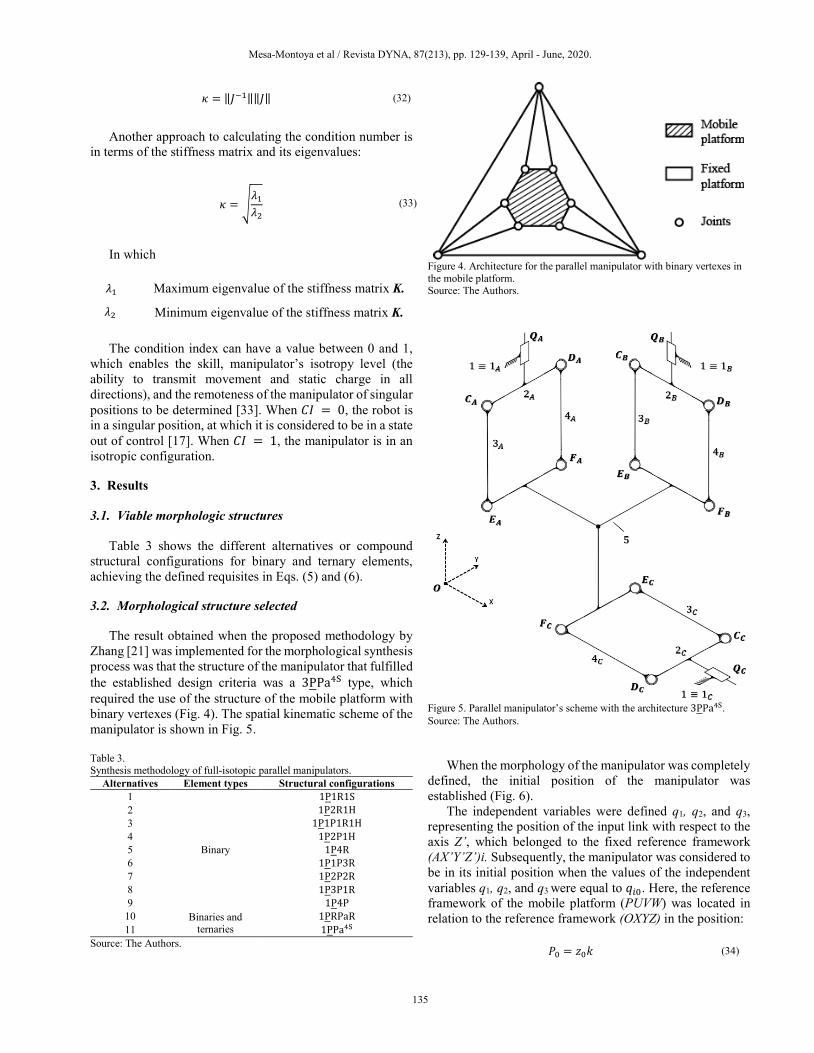
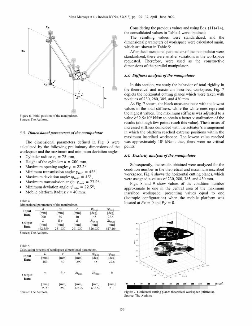
The result obtained when the proposed methodology by
Zhang [21] was implemented for the morphological synthesis process was that the structure of the manipulator that fulfilled the established design criteria was a 3PPa4S type, which required the use of the structure of the mobile platform with binary vertexes (Fig. 4). The spatial kinematic scheme of the manipulator is shown in Fig. 5.
Table 3. Synthesis methodology of full-isotopic parallel manipulators.
Alternatives Element types Structural configurations 1
Binary
1P1R1S 2 1P2R1H 3 1P1P1R1H 4 1P2P1H 5 1P4R 6 1P1P3R 7 1P2P2R 8 1P3P1R 9 1P4P
10 Binaries and ternaries
1PRPaR 11 1PPa4S
Source: The Authors.
Figure 4. Architecture for the parallel manipulator with binary vertexes in the mobile platform. Source: The Authors.
Figure 5. Parallel manipulator’s scheme with the architecture 3PPa4S. Source: The Authors.
When the morphology of the manipulator was completely defined, the initial position of the manipulator was established (Fig. 6).
The independent variables were defined q1, q2, and q3, representing the position of the input link with respect to the axis Z’, which belonged to the fixed reference framework (AX’Y’Z’)i. Subsequently, the manipulator was considered to be in its initial position when the values of the independent variables q1, q2, and q3 were equal to 𝑞𝑞𝑖𝑖0. Here, the reference framework of the mobile platform (PUVW) was located in relation to the reference framework (OXYZ) in the position:
𝑃𝑃0 = 𝑧𝑧0𝑘𝑘 (34)
Mesa-Montoya et al / Revista DYNA, 87(213), pp. 129-139, April - June, 2020.
136
Figure 6. Initial position of the manipulator. Source: The Authors. 3.3. Dimensional parameters of the manipulator
The dimensional parameters defined in Fig. 3 were
calculated by the following preliminary dimensions of the workspace and the maximum and minimum deviation angles: • Cylinder radius: 𝑟𝑟0 = 75 mm, • Height of the cylinder: ℎ = 200 mm, • Maximum opening angle: 𝜌𝜌 = 22.5𝑜𝑜 • Minimum transmission angle: 𝛾𝛾min = 45𝑜𝑜, • Maximum deviation angle: 𝜓𝜓máx = 45𝑜𝑜, • Maximum transmission angle: 𝛾𝛾max = 77.5𝑜𝑜, • Minimum deviation angle: 𝜓𝜓min = 22.5𝑜𝑜, • Mobile platform Radius: r = 40 mm. Table 4. Dimensional parameters of the manipulator.
Input Data
h ro r 𝜓𝜓max 𝜓𝜓min [mm] [mm] [mm] [deg] [deg] 200 75 40 45 22.5
Output Data
L R-r R 𝑍𝑍𝑍𝑍𝑚𝑚𝑖𝑖𝑛𝑛 𝑍𝑍𝑍𝑍𝑚𝑚𝑚𝑚𝑚𝑚 [mm] [mm] [mm] [mm] [mm]
462.359 251.937 291.937 326.937 627.164 Source: The Authors. Table 5. Calculation process of workspace dimensional parameters.
Input Data
L r R 𝜓𝜓max 𝜓𝜓min [mm] [mm] [mm] [deg] [deg] 460 40 290 45 22.5
Output Data
ro R-r 𝑍𝑍𝑍𝑍min 𝑍𝑍𝑍𝑍max h
[mm] [mm] [mm] [mm] [mm] 75.27 250 325.27 635.52 210
Source: The Authors.
Considering the previous values and using Eqs. (11)-(14), the consolidated values in Table 4 were obtained:
The resulting values were standardized, and the dimensional parameters of workspace were calculated again, which are shown in Table 5:
After the dimensional parameters of the manipulator were standardized, there were smaller variations in the workspace requested. Therefore, were used as the constructive dimensions of the parallel manipulator.
3.3. Stiffness analysis of the manipulator
In this section, we study the behavior of total rigidity in
the theoretical and maximum inscribed workspace. Fig. 7 depicts the horizontal cutting planes which were taken with z-values of 230, 280, 385, and 430 mm.
As Fig. 7 shows, the black areas are those with the lowest values in the total stiffness, while the white ones represent the highest values. The maximum stiffness was adjusted to a value of 2.5×10⁸ kN/m to obtain a better visualization of the results (although few points reach this value). These areas of increased stiffness coincided with the actuator’s arrangement in which the platform reached extreme positions within the maximum inscribed workspace. The lowest value reached was approximately 105 kN/m; thus, there were no critical points.
3.4. Dexterity analysis of the manipulator
Subsequently, the results obtained were analyzed for the
condition number in the theoretical and maximum inscribed workspace. Fig. 8 shows the horizontal cutting planes, which were assigned z-values of 230, 280, 385, and 430 mm.
Figs. 8 and 9 show values of the condition number approximate to one in the central area of the maximum inscribed workspace, presenting values equal to one (isotropic configuration) when the mobile platform was located at 𝑃𝑃𝑥𝑥 = 0 and 𝑃𝑃𝑦𝑦 = 0.
Figure 7. Horizontal cutting planes theoretical workspace (stiffness). Source: The Authors.

Mesa-Montoya et al / Revista DYNA, 87(213), pp. 129-139, April - June, 2020.
137
Figure 8. Horizontal planes theoretical workspace (Condition Number). Source: The Authors.
Figure 9. Cutting plane XZ in the maximum inscribed workspace. Source: The Authors.
The white area represents high values of the number of
conditioning (approximately one), which represents a configuration away from singular positions, while the black area represents the lowest (approximately zero). This zone of conditioning values approximate to one also depended on the position on the z-axis of the mobile platform; within this region, the best behavior of the conditioning number within
the range of values for 𝑃𝑃𝑧𝑧 between 210 and 420 mm was presented.
Considering the results obtained, the design workspace defined was considered to present values of the condition and stiffness numbers suitable for the operation of the manipulator.
a) Theoretical and maximum inscribed workspace
b) Workspace measures (view section)
Figure 10. Manipulator’s workspace. Source: The authors. Table 6. Calculating volume on each workspace for the parallel manipulator
Workspace Name Morphology Volume
[mm3]
Theoretical
15363236
Maximum inscribed
11122421
Designed
3185626
Source: The Authors.

Mesa-Montoya et al / Revista DYNA, 87(213), pp. 129-139, April - June, 2020.
138
3.5. Manipulator’s workspace CAD was used to obtain the theoretical workspace,
enabling the Boolean features with multi-solid bodies to be obtained. Fig. 10 (a) shows the theoretical and maximum registered workspace, in which the workspace design was located, a completely confined cylinder. These can be observed in detail in Fig. 10 (b), where the dimensions of a definite workspace are shown.
Table 6 shows the volumes of every workspace, achieved by the parallel manipulator’s design. 4. Discussion and conclusions
The proposed methodology for the morphological synthesis enables a significant number of solution alternatives to the kinematic chains to be used in the manipulator to be obtained. From the eleven possible topologies defined, the selection process led us to identify the configuration 3PPa4S as the most promising and viable in terms of the established design criteria. Moreover, the dimensional synthesis, based on the concept of maximum inscribed workspace, enabled the dimensional parameters of the manipulator to be determined and to relate them directly with the proposed dimensions in the design criteria for the workspace. When the dimensional synthesis process was incorporated into the study of the input transmission index, the aim was to generate dimensional parameters in the manipulator which enabled an adequate relation between mobility or force in the manipulator’s mobile platform with a low possibility of determining singular positions. The stiffness and dexterity maps were obtained within the manipulator's theoretical workspace in some planes of interest. The results enabled the zones of the best behavior of the condition number to be identified, and no regions of the screen within the manipulator's workspace were observed that do not have utility service due to stiffness. This corroborated the fact that the workspace was designed with the values of the condition number and stiffness suitable for the operation of the manipulator. Finally, the geometrical determination of the manipulator’s workspace was conducted using computer-aided design to obtain the theoretical maximum inscribed workspace. The result of the study is useful for the design and application of parallel manipulators, as it addresses the process of morphological synthesis and dimensional process in a more practical manner. The methods used in this study can be applied to design other parallel manipulator configurations, in which linear actuators are included as input elements.
References [1] Zhang, D., Parallel robotic machine tools. Springer, New York, USA,
2010. [2] Lou, Y., Liu, G., Xu, J. and Li, Z., A general approach for optimal
kinematic design of parallel manipulators. IEEE International Conference on Robotics and Automation, IEEE, New Orleans, LA, USA, pp. 3659-3664, 2014. DOI: 10.1017/S0263574719001577
[3] Hesse, S., Modular pick-and-place devices. From the series Blue
Digest on Automation. FESTO AG & Co, Esslingen, Germany, 2000. [4] Tam, T., Open Beam, [online]. Redmond, WA. [cited: July 10th of
2017]. Available at: URL:http://www.openbeamusa.com/. [5] Wygant, S., SeeMeCNC Team Stefan, [online]. Ligonier, Indiana,
USA. [cited: July 10th of 2017]. Available at: URL:https://www.seemecnc.com/
[6] Dinga, H., Fenga, Z., Yang, W. and Kecskeméthy, A., Structure synthesis of 6-DOF forging manipulators, Mechanism and Machine Theory, 111, pp. 135-151, 2017. DOI: 10.1016/j.mechmachtheory.2017.01.001
[7] Kong, X. and Gosselin, C. ,Type synthesis of 3-DOF Translational parallel manipulators based on screw theory, ASME Journal of Mechanical Design, 126 pp. 83-92, 2004. DOI: 10.1115/1.1637662
[8] Lee, C.C. and Hervé, J.M., On the enumeration of schoenflies motion generators, Proceedings of The 9th IFToMM International Symposium on Theory of Machines and Mechanisms, Bucharest, Romania, 2005.
[9] Rezaei, A. and Akbarzadeh, A., Study on Jacobian, singularity and kinematics sensitivity of the FUM 3-PSP parallel manipulator, Mechanism and Machine Theory 86, pp. 211-234, 2015. DOI: 10.1016/j.mechmachtheory.2014.11.009
[10] Meng, J., Liu, G. and Li, Z., A Geometric theory for analysis and synthesis of Sub-6 DOF parallel manipulators. IEEE Transactions on Robotics and Automation 24, pp. 625-649, 2007. DOI: 10.1109/TRO.2007.898995
[11] Gogu, G., Structural synthesis of fully-isotropic translational parallel robots via theory of linear transformations, European Journal of Mechanics A/Solids 23, pp. 1021-1039, 2004. DOI: 10.1016/j.euromechsol.2004.08.006
[12] Goldsztejna, A., Caro, S. and Chabert, G., A three-step methodology for dimensional tolerance synthesis of parallel manipulators, Mechanism and Machine Theory, pp. 213-234. 2016. DOI: 10.1016/j.mechmachtheory.2016.06.013
[13] Gogu, G., Fully-isotropic parallel manipulators with five degrees of freedom, IEEE International Conference on Robotics and Automation. Orlando, Florida, USA, 2006, pp. 1141-1146. DOI: 10.1109/ROBOT.2006.1641864
[14] Dolga, V. and Dolga, L., The structural synthesis of the parallel robots. Mechanika 17, pp. 288-295, 2011. DOI: 10.5755/j01.mech.17.3.505
[15] Tsai, L.W., Robot analysis: the mechanics of serial and parallel manipulators. Wiley, New York, USA, 1999.
[16] Liu, X.J. and Wang, J., Parallel kinematics: type, kinematics, and optimal design. Springer, New York, USA, 2014.
[17] Liu, X.J., Wang, J. and Oh, K.K., A New approach to the design of a DELTA robot with a desired workspace. Journal of Intelligent and Robotic Systems, pp. 209, 2004. DOI: 10.1023/B:JINT.0000015403.67717.68
[18] Tao, D.C., Applied linkage synthesis. Addison-Wesley, Reading, 1964, pp. 7-12.
[19] Sharma, C.S. and Purohit, K., Theory of mechanisms and machines. Eastern Economy eds. Prentice-Hall, New Delhi, India, 2006.
[20] Martin, G.H., Kinematics and dynamics of machines. McGraw-Hill, New York, USA, 1982.
[21] Gao, Z., Zhang, D., Hu, X. and Ge. Y., Design, analysis and stiffness optimization of a three degree of freedom parallel manipulator, Robotica, 28, pp. 349-357, 2010. DOI: 10.1017/S0263574709005657
[22] Kelaiaia, R., Company, O. and Zaatri, A., Multiobjective optimization of a linear Delta parallel robot, Mech. Mach. Theory, 50, pp. 159-178, 2012. DOI: 10.1016/j.mechmachtheory.2011.11.004
[23] Liu, X.J., Wang, J. and Gao, F., Performance atlases of the workspace for planar 3-DOF parallel manipulators. Robotica, 18, pp. 563-568, 2000. DOI: 10.1017/S0263574700002678
[24] Liu, X.J., Wang, J. and Zeng, H., Workspace atlases for the computer - aided design of the Delta Robot. Journal of Mechanical Engineering Science, 217, pp. 861-869, 2003. DOI: 10.1243/095440603322310413
[25] Arsenault, M. and Boudreau, R., Synthesis of planar parallel mechanisms while considering workspace, dexterity, stiffness and singularity avoidance, Journal of Mechanical Design, 128, pp. 69, 2006. DOI: 10.1115/1.2121747
[26] Cao, W., Yang, D. and Ding, H., A method for stiffness analysis of overconstrained parallel robotic mechanisms with Scara motion,

Mesa-Montoya et al / Revista DYNA, 87(213), pp. 129-139, April - June, 2020.
139
Robotics and Computer-Integrated Manufacturing 128, pp. 426-435, 2018. DOI: 10.1016/j.rcim.2017.08.014
[27] Gabardi, M., Solazzi, M. and Frisoli, A., An optimization procedure based on kinematics analysis for the design parameters of a 4-UPU parallel manipulator, Mechanisms and Machine Theory 133, pp. 211-228, 2019. DOI: 10.1016/j.mechmachtheory.2018.11.015
[28] Raoofian, A., Taghvaeipour, A. and Kamali A., On the stiffness analysis of robotic manipulators and calculation of stiffness indices, Mechanism and Machine Theory, 130, pp. 382-402, 2018. DOI: 10.1016/j.mechmachtheory.2018.08.025
[29] Itul, T., Gherman, B. and Pîsla, D., Comparative study of Two 2-DOF parallel mechanisms used for orientation, Mechanisms and Machine Science, 18, pp 145-157, 2014. DOI: 10.1007/978-3-319-01845-4_15
[30] Liu, X.J., Jin, Z.L. and Gao, F., Optimum design of 3-DOF spherical parallel manipulators with respect to the conditioning and stiffness indices, Mechanism and Machine Theory 35, pp. 1257-1267, 2000. DOI: 10.1016/S0094-114X(99)00072-5
[31] Pashkevich, A., Chablat, D. and Wenger, P., Stiffness analysis of overconstrained parallel manipulators. Mechanism and Machine Theory 44, pp. 966-982, 2009. DOI: 10.1016/j.mechmachtheory.2008.05.017
[32] Quintero, H.F., Mejia, L.A., Holguin, G., Diaz M.A., Herrera M, Mesa, C.A, and Daraviña, D., Manipuladores paralelos, síntesis, análisis y aplicaciones, Universidad Tecnológica de Pereira, Pereira, Colombia, 2018, pp. 137-146.
[33] Quintero, H.F., Mejia, L.A. and Diaz, M.A., Synthesis of planar parallel manipulators including dexterity, force transmission and stiffness index, Mechanics Based Design of Structures and Machines, 2019. DOI: 10.1080/15397734.2019.1615503
C.A. Mesa-Montoya, received a BSc. Eng. Mechanical Engineering in 2008 and MSc. in Mechanical Engineering in 2017. He is currently an Assistant professor and since 2015, he has worked for the Universidad Tecnológica de Pereira, Colombia in the publication of scientific papers and peer-review conference-proceedings papers. His current research interests include mechanical design, modeling, co-simulating, and development for parallel mechanism oriented toward upper and lower limb assistance and rehabilitation. ORCID: 0000-0002-9353-4575. H.F. Quintero-Riaza, received a BSc. Eng Mechanical Engineering in 1994, MSc. in Mechanical Engineering in 2000, and PhD in Mechanical Engineering in 2006. Since 1997, he has worked for the Universidad Tecnológica de Pereira, Colombia in the publication of scientific journals and as a professor for the Mechanical Engineering Department. He is also currently the director of the Research group of Manufacture Processes and Machines Design and the coordinator of the Mechanic Vibration Laboratory of the university. ORCID: 0000-0002-4275-739X. F. Gutiérrez-Madrid, received a BSc. Eng Mechanical Engineering in 2018. He is an active member of the Research group of Manufacture Processes and Machines Design of the Universidad Tecnológica de Pereira, Colombia. Currently, he works for the Universidad Tecnológica de Pereira in the publication of scientific journals, researching and as a professor for the Mechanical Engineering Department. ORCID: 0000-0002-1477-8994
Área Curricular de Ingeniería Mecánica
Oferta de Posgrados
Doctorado en Ingeniería - Mecánica y Mecatrónica
Maestría en Ingeniería - Ingeniería Mecánica
Especialización en Mantenimiento
Mayor información:
E-mail: [email protected] Teléfono: (57-4) 4259262