monterey, california - defense technical information … naval postgraduate school monterey,...
TRANSCRIPT
NPS-OR-01-001
NAVAL POSTGRADUATE SCHOOLMonterey, California
Joint Interoperability of Theater Missile Defense
Systems: Extending the Scope of Testing
by
Robert A. Koyak
October 2000
Approved for public release; distribution is unlimited.
Prepared for: Defense Information Systems Agency
Joint Interoperability Test CommandFort Huachuca, AZ 85613-7020
20001124 136
NAVAL POSTGRADUATE SCHOOLMONTEREY, CA 93943-5000
RADM David R. Ellison Richard ElsterSuperintendent Provost
This report was prepared for and funded by the Defense Information Systems Agency,Joint Interoperability Test Command, Fort Huachuca, AZ 85613-7020.
Reproduction of all or part of this report is authorized.
This report was prepared by:
ROBERT A.- KOYAKAssistant Professor ofOperations Research
Reviewed by: Released by:
R. KEVIN WOODAssociate Chairman for ResearchDepartment of Operations Research
EDAVI) W. NETZDAssociate Provost and Dean of Research
Department of Operations Research

Form approved
REPORT DOCUMENTATION PAGEOMB No 0704-0188
Public reporting burden for this collection of information is estimated to average 1 hour per response, including the time for reviewing instructions, searching existing data sources,gathering and maintaining the data needed, and completing and reviewing the collection of information. Send comments regarding this burden estimate or any other aspect of thiscollection of information, including suggestions for reducing this burden, to Washington Headquarters Services, Directorate for information Operations and Reports, 1215 JeffersonDavis Highway, Suite 1204, Arlington, VA 22202-4302, and to the Office of Management and Budget, Paperwork Reduction Project (0704-0188), Washington, DC 20503.
1. AGENCY USE ONLY (Leave blank) 2. REPORT DATE 3. REPORT TYPE AND DATES COVEREDOctober 2000 Technical
4. TITLE AND SUBTITLE 5. FUNDING
Joint Interoperability of Theater Missile Defense Systems:Extending the Scope of Testing H91257-0-46
6. AUTHOR(S)
Robert A. Koyak
7. PERFORMING ORGANIZATION NAME(S) AND ADDRESS(ES) 8. PERFORMING ORGANIZATION
Naval Postgraduate School REPORT NUMBER
Monterey, CA 93943 NPS-OR-01-001
9. SPONSORING/MONITORING AGENCY NAME(S) AND ADDRESS(ES) 10. SPONSORING/MONITORINGDefense Information Systems Agency AGENCY REPORT NUMBERJoint Interoperability Test Command
Attn: Leo HansenFort Huachuca, AZ 85613-7020
11. SUPPLEMENTARY NOTES
12a. DISTRIBUTION/AVAILABILITY STATEMENT 12b. DISTRIBUTION CODE
Approved for public release; distribution is unlimited.
13. ABSTRACT (Maximum 200 words)Assuring the interoperability of a theater missile defense (TMD) family of systems (FoS) is a challenging problem with manydifferent facets. Under a concept of interoperability that is based on competition among interfacing systems for reportingresponsibility on tracks, the least performing system can degrade the performance of the entire family. A program ofinteroperability testing must therefore emphasize operability in addition to conformance to message standards. This reportexamines interoperability testing of a TMD FoS from perspectives ranging from the statistical validity of tracking algorithmsto the integrity of track messaging. Recommendations for extending interoperability testing in these areas are made. Testingshould be conducted in a manner that focuses attention on deficiencies in both the concept and operations of a TMD FoS. Inparticular, interoperability testing should be structured to demonstrate the effects of system-level registration errors (bias) onFoS operations. A three-tiered "test, registration, re-test" procedure can satisfy this objective with minimal disruption totesting under current (TADIL J) message standards.
14. SUBJECT TERMS 15. NUMBER OFjoint interoperability testing, testing and evaluation, theater missile defense, PAGES
tracking and correlation 5816. PRICE CODE
17. SECURITY CLASSIFICATION 18. SECURITY CLASSIFICATION 19. SECURITY CLASSIFICATION 20. LIMITATION OFOF REPORT OF THIS PAGE OF ABSTRACT ABSTRACTUnclassified Unclassified Unclassified UL
NSN 7540-01-280-5800 Standard Form 298 (Rev. 2-89)Prescribed by ANSI Std 239-18
Joint Interoperability of Theater Missile DefenseSystems: Extending the Scope of Testing
by
Robert A. Koyak
October 2000
Prepared for: Defense Information Systems AgencyJoint Interoperability Test CommandFort Huachuca, AZ 85613-7020
Joint Interoperability of Theater Missile Defense Systems: Extending the Scope of Testing
TABLE OF CONTENTS
Executive Summary ................................................... 11i
Section 1. Introduction ................................................ 1I
Section 2. Technical Background...................................... 3
2.1 The Astrodynamics of Ballistic Missile Trajectories ............. 32. 1.1 Coordinate Systems for Missile Tracking................... 42.1.2 Dynamic Modeling........................................5
2.2 The Measurement Process...................................... 8
2.3 Estimation Techniques for Ballistic Missile Trajectories ......... 10
2.4 Impact Point Prediction ........................................ 13
2.5 Launch Point Estimation ....................................... 14
2.6 Multiple-Target Tracking and Correlation....................... 14
2.7 Sensor Bias, Registration, and Multiple-Sensor Fusion........... 15
Section 3. Interoperability and Department of DefenseMessage Standards........................................ 18
3.1 TADIL Message Standards..................................... 18
3.2 Track Quality and Reporting Responsibility..................... 183.2.1 Factors That Affect the Accuracy of TQ Numbers........... 193.2.2 Effect of TQ Number Inaccuracy on Interoperability ........ 20
3.3 Quantitative Requirements for Space-Track Messaging........... 213.3.1 Units of Measurement..................................... 213.3.2 Covariance Reporting ..................................... 213.3.3 About Numerical Accuracy................................ 243.3.4 Launch-Point Estimate Reporting...........................253.3.5 Impact-Point Prediction Reporting......................... 25
3.4 Correlation Under TADIL Message Standards................... 26
3.5 Data Registration Under TADIL Message Standards............. 273.5.1 The Data Registration Imperative...........................283.5.2 Integrating Data Registration Into Operations ............... 28
-1-
Joint Interoperability of Theater Missile Defense Systems: Extending the Scope of Testing
Section 4. Joint Interoperability Testing: Current Approaches ........... 31
Section 5. Extending the Scope of Interoperability Testing ............... 36
5.1 Recommendations ...................................................... 36
5.2 Additional Metrics for Interoperability Testing .................... 42
B ibliography ..................................................................... 45
List of Acronyms ................................................................ 48
-ii-
Joint Interoperability of Theater Missile Defense Systems: Extending the Scope of Testing
Executive Summary
Assuring the interoperability of a theater missile defense (TMD) family ofsystems (FoS) is a challenging problem with many different facets. Procedures for themanagement of communication between constituent systems must be carefully articulatedto ensure that information is processed in both a timely and accurate manner. But,necessary as they are, such procedures alone cannot assure interoperability. A family ofsystems that complies with a set of communication standards may fail to interoperate fora variety of reasons:
"* Measurements obtained from a constituent system may be subject to systematicerror (bias)
"* The communication standard either may not require or may not facilitate thetransmission of critical information between systems
"* Data processing may be based on incorrect assumptions
"* Coordination of data processing across systems may be inadequate.
The Joint Interoperability Test Command (JITC) has recognized thatinteroperability testing of a TMD FoS requires more than testing for standardsconformance. The purpose of this report is to recommend testing concepts and metricsthat the JITC can adopt to augment its interoperability testing program for TMD FoS,particularly in the area of functional interoperability. The recommendations, which aresummarized below, pertain specifically to a TMD FoS that communicates over a JointData Network (JDN) with TADIL J messaging.
Recommendation 1. In TMD FoS interoperability testing based on a TADIL J networkmessaging platform (e.g. JDN), interfacing systems should be instructed that all J3.6messages must contain full covariance matrices.
The JITC has observed that covariance matrices are not routinely transmittedduring TMD FoS testing. This omission has serious, negative consequences forinteroperability. The TADIL J message standard (MIL-STD-6016A) does not present aclear requirement for transmitting complete covariance matrices with a track report. It isrecommended that the message standard make doing so a requirement. In the meantime,the JITC should require that all systems routinely include the full covariance matrix intheir track reports during interoperability testing.
-iii-
Joint Interoperability of Theater Missile Defense Systems: Extending the Scope of Testing
Recommendation 2. Transmission of a numerically accurate covariance matrix is aninteroperability issue. The JITC should conduct specialized testing to examine whethereach of the interfacing systems can calculate, encode, and decode covariance matricesaccurately.
Covariance matrices are required to estimate trajectories, impact points, launchpoints, and uncertainties associated with each; to correlate local tracks to network tracks;and, to calculate track quality (TQ) numbers for assigning reporting responsibility (R2) ona particular track. The JITC should conduct non-event based testing, possibly on anindividual system basis, to evaluate each system's ability to transmit and processcovariance information accurately. Testing can be conducted using a pre-determined setof covariance matrices that the JITC transmits to each system for reconstruction, andanother set that each system transmits to the JITC.
Recommendation 3. Interoperability problems that arise during TMD FoS testing mayresult from problems within a particular system. A TADIL J message stream obtainedduring FoS testing may not reveal enough information to pinpoint the source of aproblem. Interoperability testing should include a component in which interfactingsystems operate in non-FoS (autonomous) mode. In autonomous mode, each interfacingsystem tracks what it can, and provides full messaging based on its local tracks, withoutregard to reporting responsibility (R2) rules.
A TMD FoS is fragile in the sense that one interfacing system can degrade theperformance of the entire family. A system with sensors that exhibit severe, butundetected, bias can thwart interoperability by overstating its track quality, therebyacquiring R2 and preventing more qualified systems from reporting on the track. It istherefore difficult, if not impossible, to separate FoS interoperability from systemoperability under the JDN concept. The JITC should not be restricted to assessinginteroperability solely on the basis ofjoint (TADIL J) messaging.
Test scenarios should be conducted in both FoS (joint) mode and in non-FoS(autonomous) mode. In addition to allowing the JITC to isolate problems that arespecific to an individual system, a comparison of both modes of testing will allow theJITC to measure the benefits of joint tracking relative to the same assets operatingautonomously.
-iv-
Joint Interoperability of Theater Missile Defense Systems: Extending the Scope of Testing
Recommendation 4. Estimation of track position-velocity missile state vectors cannotbe reduced to a single, valid formulation. In the absence of a single, standard trackingalgorithm that each interfacing system of a FoS must adopt, tracking algorithms can beexpected to vary across systems. As part of interoperability testing, the JITC should haveeach system declare, in the form of a written report, important aspects of its trackingalgorithms as they pertain to tracking ballistic missiles.
The astrodynamics of missile trajectories is a well-studied area of physics, and itis expected that each system in a FoS will reflect the current state of knowledge in itstracking algorithms. However, there are modeling issues that may be handled differentlyacross systems, perhaps unsatisfactorily in some cases. Inspection of computer code thatis used to implement motion models may not be possible, due to the desire of developersto protect their intellectual property; and it may not be productive for the JITC toundertake such inspection in any case. As an alternative, the JITC should develop aquestionnaire to be submitted to each system in a FoS test. The questionnaire shouldelicit detailed information about the modeling decisions that were incorporated into eachsystem's tracking software.
Recommendation 5. The JITC should assess the models that are used for generatingmissile trajectories in event simulators. A criterion for suitability is whether live-missiletrajectories (e.g. Coral Talon) are within a "high confidence set" of trajectories that canbe obtained if the event simulator is primed with the same initial conditions as the truthtrajectory.
Modeling and simulation (M&S) is an important tool for testing TMD FoSinteroperability. Many of the interoperability shortcomings that have been observed todate are manifested in simulated event scenarios. But there is concern that simulatedmissile trajectories may not be fully realistic. If that is the case, a TMD FoS that istrained primarily on simulated events may perform disappointingly in real-worldsituations. Unfortunately, there are relatively few data on real missile trajectories thatcan be used to develop a truly complete empirical model. But existing data may allowcomparisons to be made between simulated and real missile tracks. The JITC should usereal data to "prime" event simulators to measure the discrepancy between true andsimulated trajectories. By doing so the JITC can achieve a better understanding of thesuitability of its testing tools.
-- V-

Joint Interoperability of Theater Missile Defense Systems: Extending the Scope of Testing
Recommendation 6. Data registration is an important activity to ensuring theinteroperability of a TMD FoS. Unfortunately, TADIL J does not provide the messagingresources that are needed to make on-going and interactive data registration an integralpart of the operation of a TMD FoS. It is therefore unlikely that the JITC can address thissituation directly in testing. But the JITC can, in a realistic manner, incorporate aregistration interval into its interoperability assessment procedures.
The data registration provisions of the JDN interoperability concept are not wellarticulated. TADIL J provides few messaging resources for systems to share informationthat is needed to make data registration an integral part ofjoint tracking activity. As aresult, systems can introduce biased measurements into the network, encounteringvirtually no firewalls. It is doubtful that a TMD FoS can ever become truly interoperablewithout overcoming this deficiency. To become so would require modification ofMIL-STD-6016A or the adoption of a different messaging concept. It may be beyond thescope of the JITC to address this concern directly. Instead, the JITC should attempt tomeasure the improvement that would be achieved by integrating data registrationprocedures into TMD FoS operations. This can be done by conducting testing in threestages: (1) pre-test, (2) registration interval, and (3) re-test. The pre-test entails jointtracking as currently done in interoperability testing. It is followed by a registrationinterval, which gives each system the opportunity to track objects with knowntrajectories. Systems use this information to refine its data registration before the re-testis conducted. Comparison of test metrics between the pre-test and re-test will allow theJITC to measure improvement due to the use of data registration procedures.
Recommendation 7. The JITC should adopt metrics related to track latency, which isthe difference in time reported in a space track message and time as appropriate to theposition and velocity of the object reported in the same track message. Track latencyreflects the time required to process and transmit a space track message that is not fullyreflected in the reported time.
In tracking a high-velocity target such as a ballistic missile, a small timing errorcan translate into a large physical distance error. Track latency errors may occur even ifa system is capable of measuring track position and velocity without error and if its clockis perfectly synchronized. By measuring track latency the JITC will be able to isolatetracking errors due to latency and tracking errors due to other causes.
-vi-

Joint Interoperability of Theater Missile Defense Systems: Extending the Scope of Testing
1. Introduction
This reports describes research that was conducted on statistical aspects ofinteroperability testing of theater missile defense (TMD) families of systems (FoS),during the summer of 2000. The interoperability problem in this context is a deep one, asanyone who is familiar with it knows. Setting aside the challenge of engaging a hostileballistic missile with defensive countermeasures, it is a challenge simply to come to aunified understanding of what exists in the air space. Different systems must be able to"talk" to each other in a timely and accurate manner before a FoS defensive concept canhope to supersede the benefits of a "single system" defensive concept.
The communications backbone of the TMD FoS concept that the JointInteroperability Test Command (JITC) has tested is TADIL J and its associated standard(MIL-STD-6016A). TADIL J is the networking platform upon which the Joint DataNetwork (JDN) is based. TADIL J is a well-endowed resource for sharing technicalinformation on air or space threats between the interfacing systems of a FoS. However,the message standard does not attempt to enforce rigid uniformity on the content andtransmission of technical information. As a result, flexibility is maintained somewhat atthe expense of coherence and completeness in communicating this information.
The nearly uniform assessment of the TMD FoS concept is that it falls short ofexpectations when it is loosely confederated. Data registration is an area where this isparticularly evident. A TMD FoS is not robust to measurement biases that are exhibitedby even a few of its sensors. Under ideal conditions where there is no bias,interoperability issues are substantial. Where such biases are present, interoperabilityproblems may be insurmountable. This is because each interfacing system depends onthe "good faith" effort of every other system to report its information free of removablesystematic errors.
Data registration is a collection of procedures, including calibration, that aredesigned to remove measurement bias. MIL-STD-6016A recognizes the importance ofthis activity, and recommends that interfacing systems adopt data registration procedures.But there is little standardization or enforcement. As a result, the JITC has observedclassical manifestations of systematic errors in TMD FoS testing, which include thecreation of multiple tracks for the same object, the premature dropping of valid tracks, thecreation of tracks that do not represent real objects, and tracks that are not physicallyplausible.
Another problem that loose confederation poses is that system software is notstandardized. Different tracking and correlator algorithms may be in use simultaneously.Statistical criteria for associating objects to tracks may be different. In TMD FoS testingunder JDN, interfacing systems hold their own local tracking data, and systems' softwaretools are essentially "black boxes." This makes it difficult to trace interoperabilityproblems to their cause.
Joint Interoperability of Theater Missile Defense Systems: Extending the Scope of Testing
An alternative concept ofjoint tracking is the Joint Composite Tracking Network(JCTN), which is still under development. Unlike JDN, JCTN requires that each systemrun the same software for basic tracking tasks. In the developmental stage,benchmarking software is integrated into the software, which facilitates the automaticgeneration of testing metrics whenever FoS testing is conducted. However, themessaging platform to support this concept has yet to be developed, and to do so will facesignificant challenges.
This report is organized into five sections. Section 2 discusses missile trackingfrom statistical and physical viewpoints. The models that are used in tracking aredescribed in this section. Section 3 discusses the TADIL message standards and howtheir technical content affects interoperability. In particular, the TQ Number concept ofassigning Reporting Responsibility is discussed. Section 4 is a review of metrics that areused for measuring interoperability by the JITC, and in benchmarking by JCTN. Manyof the JCTN benchmarks are related to interoperability, and some can be adapted for useby the JITC. Section 5 offers seven recommendations for improving interoperabilitytesting of a TMD FoS, with respect to the technical content of space track messages.New performance metrics are also proposed in Section 5.
-2-
Joint Interoperability of Theater Missile Defense Systems: Extending the Scope of Testing
2. Technical Background
A TMD FoS that is designed to track and engage missile threats must contendwith a myriad of technical problems that have eluded solution for decades. The design ofincreasingly accurate sensors and faster computers offers new possibilities for bringworkable multisensor tracking systems into fruition. Counterbalancing this is that theability of adversaries to implement countermeasures is also increasing both in scope andeffectiveness. What this means is that not only must the FoS be able to track a single,high-velocity ballistic object accurately, it must also be able to do so for many suchtracks, while distinguishing those that represent ballistic missiles from those that do not.
Although one system in the family may use analytical techniques that differ fromthose of another, there are a number of principles that should be reflected in anyanalytical approach. These principles are discussed briefly in this chapter.
2.1 The Astrodynamics of Ballistic Missile Trajectories
The flight of a ballistic missile from the time of launch to the time of impact withthe surface of the earth can be divided into two phases, depending on the forces that actupon the vehicle:
"* The boost phase occurs from the time of launch until the time that the motors nolonger provide thrust to the missile. The boost phase may last from less than aminute to several minutes, depending on the design of the missile. In addition togravity, atmospheric lift and drag, and possibly other (minor) perturbing forces,the missile is subject to a force provided by the use of its fuel. The latter is acombined effect due to the kinetic energy released when fuel is burned, and thegradual loss of mass that the missile experiences at the same time. The boostphase may consist of several (two or three) distinct subphases of boosting, andsome missiles may be capable of producing "corrective" thrust during midcourse.
"* The ballistic phase occurs from the end of the boost phase until the time of impactwith the surface of the earth. The ballistic phase of a theater-area missile may lastfrom several minutes to over one-half hour, depending on the range of the missile.During the ballistic phase the only forces that act upon the missile are those due togravity, atmospherics, and perturbations of external origin.
In some treatment of this subject, the ballistic phase is further divided into exo-atmospheric and re-entry phases. During the exo-atmospheric phase, the missile is atsufficient altitude that the density of the atmosphere does not significantly affect motionof the missile. During the re-entry phase the missile enters the lower atmosphere beforeits imminent impact with the earth. Where the transition from the exo-atmospheric to there-entry phase occurs is somewhat arbitrary, although the distinction may have practicalvalue in certain contexts. Atmospheric density is an approximately exponentiallydecreasing function of altitude. At altitudes above 30 km atmospheric density is widely
-3-

Joint Interoperability of Theater Missile Defense Systems: Extending the Scope of Testing
regarded negligible. By accurately modeling atmospheric density, both the exo-atmospheric and re-entry phases can be described in a unified manner.
2.1.1 Coordinate Systems for Missile Tracking
Physical laws dictate that that the motion of a negligibly small body (i.e., amissile) with respect to Earth, not accounting for other-body gravitational forces, isdescribed relative to the center of mass of the earth in inertial coordinates. An Earth-centered inertial (ECI) coordinate system is therefore the preferred one for describing thetrajectory of a ballistic missile. The commonly used Earth-centered Earth-fixed (ECEF)coordinate system has its origin at the center of the earth, with axes passing through thepoints 0' Latitude 00 Longitude (equator at Greenwich Meridian), 00 Latitude 900 ELongitude, and the North Pole. Because the ECEF coordinate system rotates with theearth, it is not inertial. It is, however, possible to "fix" the ECEF coordinates at the timethat a missile is first detected and correct for rotation of the earth as time progresses.
From the point of view of a sensor located on the surface of the earth, a polarcoordinate system centered at the position of the sensor more naturally corresponds to itsmeasurement process. Three characteristics typically are measured:
"* the range, or distance of the missile from the sensor
"* the azimuth angle or angle of rotation (at the sensor) from "true north" to themissile.
"* the elevation angle that a line from the missile to the sensor makes with the planetangent to the earth at the sensor location
These attributes comprise what is often referred to as the sensor-RAE (range, azimuth,elevation) coordinate system. The sensor-RAE coordinate system is non-inertial becausethe sensor moves with the rotation of the earth.
For radars in particular, estimates of the RAE quantities are obtained directlythrough processing of the radar cross-section (RCS). It has been suggested thatmeasurement errors are nearly independent in sensor-RAE coordinates, which is anadvantage in the design of efficient estimation strategies. By contrast, infrared (IR)sensors provide only "line of sight" (LOS) measurements from the sensor to the target.From one LOS measurement two angles can be determined but not the range. Using twoLOS measurements it is possible to determine the range using triangulation.
It is possible to convert between a sensor-RA-E coordinate system and the ECEFcoordinate system using simple mathematical relationships. Such conversion isnecessary to express data from multiple sensors in a common reference frame. But,conversion from sensor-centered to earth-centered coordinates can impart systematictracking errors if the position of the sensor in ECEF coordinates is not known accurately.
-4-
Joint Interoperability of Theater Missile Defense Systems: Extending the Scope of Testing
This underscores the need to have well-developed and followed procedures for sensoralignment in any multisensor tracking system.
When tracking is conducted in a Cartesian coordinate system centered at theearth, for display purposes it is sometimes convenient to convert positional information togeodetic latitude, longitude, and altitude. This applies in particular to the estimation of amissile's launch and impact points. Conversion between Cartesian (ECEF) and geodeticcoordinates is mathematically straightforward. The WGS-84 Earth Model provides Earthdata (based on non-sphericity of the earth) that are currently considered to be the mostaccurate for performing these conversions.
2.1.2 Dynamic modeling
The motion of a missile relative to the center of the earth can be described using anonlinear dynamic model. Assuming that Earth gravitation is the only force that actsupon the missile, and that the earth is perfectly spherical, the following relationship dueto Netwon's Second Law holds:
i(t) = pr(t)
I r(t)I 3
The symbol r(t) refers to the three-dimensional position of the missile in an interialcoordinate system such as ECI, or ECEF at a fixed point in time. Position is described asa function of time, denoted t. The symbol Ir(t) I is the norm of the position vector, given
by I r(t) = Vr2 (t) + r (t) + r,2 (t). The symbol F(t) refers to the three-dimensional
acceleration vector, which is obtained by taking the second derivatives of each of the r(t)coordinates with respect to time. Similarly, i(t) refers to the first derivatives, or the
velocity of the missile in three-dimensional space. The symbol p refers to the earth'sgravitational constant, given by p = 3.986012 x 101 km3/s2. It is assumed here thatmetric units are used, so that r(t) is measured in kilometers (kin), i(t) in kilometers persecond (km/s), and iF(t) in kilometers per squared second (km/s2).
The position and velocity of the missile can be combined into a single 6-dimensional state vector x(t) = [r(t), i(t)]. The first derivative of x(t) is then completelydescribed in terms of x(t):
40= [N(t) F(t)] =[(t) r(t) 1 = F(x(t)).
From this relationship, is is seen that x(t) is the solution to a first order, nonlineardifferential equation. Solutions to this equation have several well-known properties:
-5-
Joint Interoperability of Theater Missile Defense Systems: Extending the Scope of Testing
"* For an object that does not escape Earth's gravitational field (e.g., a ballisticmissile), r(t) can be described as an ellipse with one of its two foci located at thecenter of the earth.
"* Knowing both r(t) and i(t) at one point in time, or r(t) at three distinct points intime, is sufficient to characterize the elliptical trajectory.
Of course, the earth is not perfectly spherical, and Earth's gravity is not the onlyforce that acts upon a missile during its flight. The slight bulge at the equator of the earthexerts a torque on the elliptical plane of the missile's trajectory. Stated another way,Earth's gravitational force is greatest at the equator, and decreases slightly as geodeticlatitude approaches that of the North or South Pole. This effect is usually accounted forby correcting the gravitational constant p, depending on latitude, using formulas that arewidely available. Although the resulting correction is usually small, it may be importantif it is desired to take countermeasures against a high-velocity target.
Other forces that act upon the missile are orders of magnitude greater than thevariable effect of gravity. During the boost phase, the missile is subject to thrust from itsmotors, continual diminution of its mass, and atmospheric drag and lift as the missiledeparts the lower atmosphere. To account for these factors requires detailed informationabout the design of the missile and the manner in which it was launched, which may ormay not be available. During the ballistic phase, the missile is continually subject toatmospheric lift and drag, which become increasingly significant forces as the missilepasses through the lower atmosphere towards the surface of the earth. During bothphases the ballistic coefficient captures features of the missile that determine howatmospheric lift and drag affect its motion.
It is possible to extend Newton's gravitational model to account for the factorsdescribed above, resulting in a nonlinear dynamic model of the same generic form
it)= F(x(t)). This subject is discussed in Stevens and Lewis (1992) and in otherpublished sources. Specification of the dynamic model may vary depending on thecontext and information about the missile that is available. The transition from the boostto the ballistic phase represents a change in the astrodynamic properties of the missile,and two different dynamic models may be used.
The ballistic coefficient presents a modeling issue that requires careful attention.If the missile is of known type, intelligence may supply information that, if correct,would allow the ballistic coefficient to be determined precisely. However, operatingunder the assumption of correctness may be risky, and in any case it is necessary toconsider the case where such information is absent. An effective approach is toincorporate the ballistic coefficient (or drag force, determined from the ballisticcoefficient) into the state vector. This approach is discussed in Cardillo, Mrstik andPlambeck (1999), where the authors report considerable improvement in tracking ballisticmissiles at Kwajalein Missile Range as a result of this modification.
-6-
Joint Interoperability of Theater Missile Defense Systems: Extending the Scope of Testing
A dynamic motion model cannot perfectly predict the trajectory of a ballisticmissile. One reason is that a model accounts for known physical forces only to within acertain degree of accuracy. Refinements to the model (e.g. to account for variations inthe Earth's gravitational field) can be made to reduce, but not eliminate, theseapproximation errors. Another reason is that a missile is subject to perturbations in itstrajectory due to forces that are not fixed and predictable. These perturbations are oftenaccounted for by including a random component, referred to as process noise, in themodel. The dynamic model then takes the form of a first-order, nonlinear stochasticdifferential equation: i(t) = G(x(t),E (t)), where £ (t) is a random vector representing theprocess noise. If the process noise is additive, then G(x(t),e (t)) = F(x(t)) + Qe (t),where Q is a matrix of known form. The process noise - (t) is usually of smallerdimension than the state vectorx(t). For example, if the state vector is 6-dimensional,the process noise may be 3-dimensional and apply only to the derivatives of the velocity.In this case Q would be a 6 x 3 matrix.
The probability distribution that is used to describe the process noise is animportant aspect of the model that has received little attention in the published literature.There is a tendency to use Gaussian (normal) distributions with simple covariancestructures, which is computationally convenient but not necessarily grounded inastrodynamical principles.
An alternative to modeling motion in Cartesian (ECI or ECEF) coordinates is touse polar (sensor-RAE) coordinates. As noted previously, this may be desirable from thepoint of view that sensor-RAE coordinates more naturally express how sensormeasurements are obtained. Cardillo et al. (1999) provide dynamic modeling equationsfor tracking ballistic missiles in sensor-RAE coordinates.
The models described above apply to "continuous" time, but in measurementsituations the position and velocity of a target are usually observed at discrete, equally-spaced time points. Continuous-time nonlinear models are often linearized using thedefinition of a derivative. For example, x(t+A) ; x(t) + AG(x(t),6 (t)) is thediscreteized, linear approximation to the model i(t) = G(x(t),c (t)).
In summary, there is no one "correct" way to formulate a dynamic model thatdescribes the motion of a ballistic missile. How it is formulated depends on theinformation available (e.g. the ballistic coefficient) and the coordinate system that isused. Regardless of how the dynamic model is formulated, the following elementsshould be present:
Gravitational force represented by Newton's formula. A "flat Earth" version ofthis formula may be acceptable if tracking is done over short distances (e.g,during the boost phase).
-7-
Joint Interoperability of Theater Missile Defense Systems: Extending the Scope of Testing
"* Earth's gravitational field represented as variable due to non-sphericity of theearth. Approximations are available using first- and second-order zonalpolynomials.
"* Atmospheric drag represented using the ballistic coefficient (known or estimated)and density of the atmosphere. Atmospheric density can be approximated as afunction of altitude using available formulas (Zarchan, 1999).
"* Thrust and pitch-over angle included during the boost phase.
"* Earth's rotation included as a continual angular displacement if tracking isperformed in non-inertial coordinates.
"* Process noise incorporated into the model in a scientifically defensible manner.
2.2 The Measurement Process
A sensor such as a radar does not perfectly measure the position and velocity of atarget that it tracks. Data processing is subject to random error and bias (systematicerror) that have different characteristics across sensors. Usually, these errors areexpressed in sensor-RAE coordinates, which is the "natural" coordinate system for sensormeasurement. Radars with Doppler can use this information to improve rangemeasurement, to produce velocity measurements, or both. The following assumptions aretypically made:
"* Sensor measurements are unbiased, in range, azimuth, and elevation;
"* Random errors follow normal (Gaussian) probability distributions, with
covariance matrices that may depend upon time;
"* Random errors for range, azimuth, and elevation are statistically independent;
"* Random errors are independent across time.
Operating under these -assumptions greatly simplifies the estimation of missiletrajectories. However, a violation of any one of them could have undesirableconsequences. If a sensor is miscalibrated, for instance, systematic errors will be presentin all of its measurements. Data registration, which is discussed in section 2.7 below, is aprocess by which an operator or system user attempts to remove systematic errors fromsensor measurements. Modeling of the measurement process assumes that effective dataregistration procedures are in place, so that only random errors need to be considered.
-8-
Joint Interoperability of Theater Missile Defense Systems: Extending the Scope of Testing
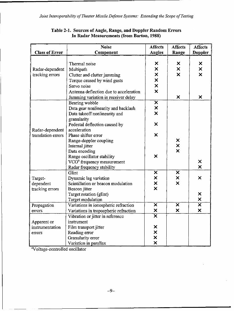
Table 2-1. Sources of Angle, Range, and Doppler Random ErrorsIn Radar Measurements (from Barton, 1988)
Noise Affects Affects AffectsClass of Error Component Angles Range Doppler
Thermal noise X X XRadar-dependent Multipath X X Xtracking errors Clutter and clutter jamming X X X
Torque caused by wind gusts XServo noise XAntenna deflection due to acceleration XJamming variation in receiver delay X XBearing wobble XData gear nonlinearity and backlash XData takeoff nonlinearity and XgranularityPedestal deflection caused by X
Radar-dependent accelerationtranslation errors Phase shifter error X
Range-doppler coupling XInternal jitter XData encoding XRange oscillator stability XVCOa frequency measurement XRadar frequency stability XGlint X X
Target- Dynamic lag variation ×X Xdependent Scintillation or beacon modulation X Xtracking errors Beacon jitter X
Target rotation (glint) XTarget modulation X
Propagation Variations in ionospheric refraction X X Xerrors Variations in tropospheric refraction X X X
Vibration or jitter in reference XApparent or instrumentinstrumentation Film transport jitter Xerrors Reading error X
Granularity error XVariation in parallax X I×I
aVoltage-controlled oscillator
-9-
Joint Interoperability of Theater Missile Defense Systems: Extending the Scope of Testing
Chapter I11 of Barton (1988) gives a thorough discussion of errors that occur inradar measurements. Table 2-1 (which combines information from Tables 11. 1, 11. 6,and 11.7 of Barton) illustrates that random errors in angle (azimuth and elevation), range,and Doppler measurements are subject to a number of common factors. This overlapgives ample reason to question the treatment of measurement errors in sensor-RAEcoordinates as statistically independent, although a common error source may, inprinciple, affect the coordinates in different ways.
Some of the noise components listed in Table 2-1 appear capable of persisting forperiods of time, possibly across consecutive radar measurements. If that is the case, thenthe assumption of independent random errors across time is likely to be violated.Barton's (1988) spectral analysis of angle-tracking errors, which found a pronouncedcyclic component and other evidence of departure from a white-noise spectrum, suggeststhat there may be good reason to closely examine the validity of this assumption.
The assumption of normality, often made for convenience reasons, deservesscrutiny. One of the defining traits of a normal distribution is that large deviations (i.e.,values more than three standard deviations from the mean) rarely occur. This assumptionjustifies the use of estimation procedures that are optimized for normality, but performbadly in the presence of even a small number of large deviations. These proceduresinclude the Kalman filter, which is widely used for tracking ballistic missiles.
Finally, it should be mentioned that any statement of the precision of a sensor(e.g. in the form of a covariance matrix) should reflect its practical operation when,where, and how the sensor is to be employed. Manufacturer's specifications, which oftenassume that equipment is new, properly calibrated, and operated under ideal conditions,can be overly optimistic in assessing accuracy, particularly in the presence of errors thatoriginate from external sources (see Table 2-1). Determining the operational accuracy ofa sensor is a laborious process that requires ongoing testing and experimentation.
2.3 Estimation Techniques for Ballistic Missile Trajectories
An algorithm that is used to estimate the trajectories of ballistic missiles must beboth good and fast. To illustrate, consider a ballistic missile that impacts the earth600 kmn (ground distance) from the launch site, and achieves a maximum height (atapogee) of 130 km. Ignoring boost-phase issues and atmospheric drag, this missile willimpact the earth approximately 6 minutes after launch and achieve a forward velocity ofabout 8,500 kmi/hr at the time of impact. An algorithm that uses crude approximationsmay be time-efficient but unable to localize a missile during its flight in a usable way.Similarly, a highly accurate algorithm that is computationally intensive is useless if itcannot provide its answers quickly.
Electrical engineers and other scientists have developed a variety of trackingalgorithms over the last four decades, and new algorithms continue to appear. Thesealgorithms can be classified in a number of different ways. Most of the algorithms that
-10-

Joint Interoperability of Theater Missile Defense Systems: Extending the Scope of Testing
have been described in the published literature for estimation of missile trajectories canbe broadly classified as either fixed-coefficient filters or Kalmanfilters.
Filtering techniques are based on linking a state equation to another equation thatdescribes the measurement process. Ideally, all of the relationships in the two equationsare linear, and all of the noise is Gaussian. In this case the discrete-time filtering modelhas the following form:
State equation: x(k + 1) = Fk x(k) + Qk 6 (k)
Measurement equation: y(k) = Hk x(k) + r7(k)
The state equation describes how the state (missile position, velocity, etc.) changes fromtime k to time k+L. The current state is multiplied by a known matrix Fk, and process
noise represented by the remaining term is then added. The process noise 6 (k) isassumed to be Gaussian, uncorrelated across time (white noise), with each coordinatehaving mean 0 and variance 1. Covariance and other linkage issues are addressed by thematrix Qk, which is not known and must be estimated.
The true state vector x(k) is not directly observable, and it is affected bymeasurement error. The measurement equation describes how the sensor-datavector y(k) is related to the state vector. The state vector is premultipled by a known
matrix Hk and Gaussian measurement error 7 (k) is then added. By assumption, this
measurement error is uncorrelated across time and with the process noise. Thecovariance matrix of the measurement error is assumed to be known.
The goals of estimation are the following:
"* Estimate the current state x(k) based on all data y(1), ..., y(k) available at thattime;
"* Predict a future state x(k+r) based on all data y(]), ..., y(k) available at time k;
"* Provide a smoothed estimate of a past state x(k-r) based on all data y(l), ..., y(k)available at time k;
"* Provide estimated covariance matrices for all estimated, predicted, and smoothedquantities.
Under the model described above, the Kalman filter provides a statistically optimalmeans for satisfying all of these goals. In addition, the calculations are algebraicallystraightforward and well-suited to real-time implementation. When a new observationy(k+1) enters the system, estimates and predictions are easily updated. The Kalman filteris the subject of numerous books and articles in the scientific literature. Grewal andAndrews (1993) is a good introductory treatment.
-11-
Joint Interoperability of Theater Missile Defense Systems: Extending the Scope of Testing
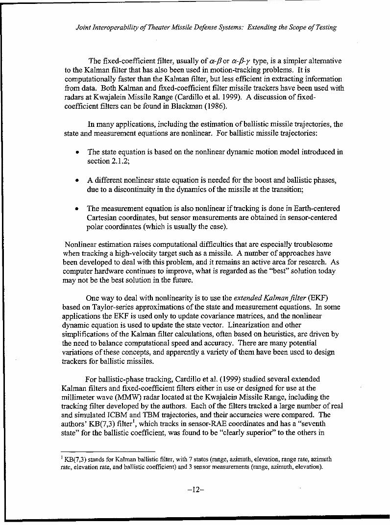
The fixed-coefficient filter, usually of a-f8 or a-fl-y type, is a simpler alternativeto the Kalman filter that has also been used in motion-tracking problems. It iscomputationally faster than the Kalman filter, but less efficient in extracting informationfrom data. Both Kalman and fixed-coefficient filter missile trackers have been used withradars at Kwajalein Missile Range (Cardillo et al. 1999). A discussion of fixed-coefficient filters can be found in Blackman (1986).
In many applications, including the estimation of ballistic missile trajectories, thestate and measurement equations are nonlinear. For ballistic missile trajectories:
"* The state equation is based on the nonlinear dynamic motion model introduced insection 2.1.2;
"* A different nonlinear state equation is needed for the boost and ballistic phases,due to a discontinuity in the dynamics of the missile at the transition;
"* The measurement equation is also nonlinear if tracking is done in Earth-centeredCartesian coordinates, but sensor measurements are obtained in sensor-centeredpolar coordinates (which is usually the case).
Nonlinear estimation raises computational difficulties that are especially troublesomewhen tracking a high-velocity target such as a missile. A number of approaches havebeen developed to deal with this problem, and it remains an active area for research. Ascomputer hardware continues to improve, what is regarded as the "best" solution todaymay not be the best solution in the future.
One way to deal with nonlinearity is to use the extended Kalman filter (EKE)based on Taylor-series approximations of the state and measurement equations. In someapplications the EKE is used only to update covariance matrices, and the nonlineardynamic equation is used to update the state vector. Linearization and othersimplifications of the Kalman filter calculations, often based on heuristics, are driven bythe need to balance computational speed and accuracy. There are many potentialvariations of these concepts, and apparently a variety of them have been used to designtrackers for ballistic missiles.
For ballistic-phase tracking, Cardillo et al. (1999) studied several extendedKalman filters and fixed-coefficient filters either in use or designed for use at themillimeter wave (MMW) radar located at the Kwajalein Missile Range, including thetracking filter developed by the authors. Each of the filters tracked a large number of realand simulated ICBM and TBM trajectories, and their accuracies were compared. Theauthors' KB(7,3) filter', which tracks in sensor-RAE coordinates and has a "seventhstate" for the ballistic coefficient, was found to be "clearly superior" to the others in
1 KB(7,3) stands for Kalman ballistic filter, with 7 states (range, azimuth, elevation, range rate, azimuthrate, elevation rate, and ballistic coefficient) and 3 sensor measurements (range, azimuth, elevation).
-12-

Joint Interoperability of Theater Missile Defense Systems: Extending the Scope of Testing
termis of both accuracy and adaptability to a variety of missile and atmosphericconditions.
Precise tracking in the boost phase is more difficult, as it depends on the launchcharacteristics and design of the missile. The primary objective of boost-phase trackingis to back-propagate the trajectory so that the launch point can be estimated. A nonlineardynamic model for boost-phase tracking is provided in Li, Kirubarajan, Bar-Shalom, andYeddanapudi (1999). Li et al. use fully nonlinear maximum likelihood estimation in"batch mode" (non-real time) to estimate the boost-phase trajectory. A Kalman filterapproach to tracking in the boost phase is provided in Blackman and Popoli (1999).
Integrating a boost-phase and ballistic-phase dynamic model is advantageousparticularly when the target is acquired at the early stages. A method for performing theintegration is to use an Interacting Multiple Model (1MM) filter. The 1MM filter usesestimated transition probabilities to discriminate between the models. San Jose (1998)found that an 1MM model performed well in tracking short-range ballistic missiles wherea switch-over from the boost phase to the ballistic phase occurred during the period ofobservation. When the transition probabilities suggest that the initial boost stage is likelyto have ended, the parameters of the boost-phase model are reset in case a second booststage is detected. Blackman and Popoli (1999) recommend a three-model 1MM filter,with the additional model used to allow for the possibility of a maneuvering target.
Although the missile trajectory estimation problem has been studied for manyyears, and the dynamics of motion have also been understood for quite some time, newalgorithms continue to be developed, and it is hard to say that a clear "winner" hasemerged. Different strategies reflect tradeoffs between accuracy, speed, and versatility.In particular, elaborated 1MM models reflect the desire for the integrated tracking of amissile during its boost stage(s), during its ballistic phase, and possibly allowing for post-boost phase maneuvers. The effectiveness of any estimation strategy should be judged ona combination of scientific validity and performance.
2.4 Impact Point Prediction
With state and measurement equations specified, estimation of the point on thesurface of the earth where the missile will make impact is conceptually straightforward.At time k, the estimated state vector i(k I k) contains the most up-to-date inform-ationavailable about the properties of the missile trajectory. Starting from this estimate, thedynamic state equation can be propagated forward, in continuous time and withoutprocess noise, until the norm of the state vector is equal to the radius of the earth at theindicated latitude (in Earth-centered Cartesian coordinates), or until the elevation is zero.Both the time of impact and the impact point can be estimated in this manner.
Propagation entails numerical integration of the first-order nonlinear differentialequation associated with the state equation. It is important that this be done using agood-quality numerical integrator, because integration is prone to the accumulation of
-13-
joint interoperability of Theater Missile Defense Systems: Extending the Scope of Testing
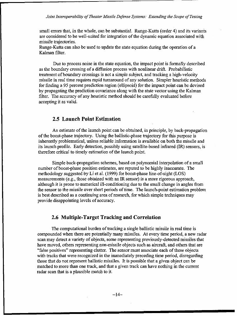
small errors that, in the whole, can be substantial. Runge-Kutta (order 4) and its variantsare considered to be well-suited for integration of the dynamic equation associated withmissile trajectories.Runge-Kutta can also be used to update the state equation during the operation of aKalman filter.
Due to process noise in the state equation, the impact point is formally describedas the boundary crossing of a diffusion process with nonlinear drift. Probabilistictreatment of boundary crossings is not a simple subject, and tracking a high-velocitymissile in real time requires rapid turnaround of any solution. Simpler heuristic methodsfor finding a 95 percent prediction region (ellipsoid) for the impact point can be devisedby propagating the prediction covariance along with the state vector using the Kalmanfilter. The accuracy of any heuristic method should be carefully evaluated beforeaccepting it as valid.
2.5 Launch Point Estimation
An estimate of the launch point can be obtained, in principle, by back-propagationof the boost-phase trajectory. Using the ballistic-phase trajectory for this purpose isinherently problematical, unless reliable information is available on both the missile andits launch profile. Early detection, possibly using satellite-based infrared (IR) sensors, istherefore critical to timely estimation of the launch point.
Simple back-propagation schemes, based on polynomial interpolation of a smallnumber of boost-phase position estimates, are reputed to be highly inaccurate. Themethodology suggested by Li et al. (1999) for boost-phase line-of-sight (LOS)measurements (e.g., those obtained with an JR sensor) is a more rigorous approach,although it is prone to numerical ill-conditioning due to the small change in angles fromthe sensor to the missile over short periods of time. The launch-point estimation problemis best described as a continuing area of research, for which simple techniques mayprovide disappointing levels of accuracy.
2.6 Multiple-Target Tracking and Correlation
The computational burden of tracking a single ballistic missile in real time iscompounded when there are potentially many missiles. At every time period, a new radarscan may detect a variety of objects, some representing previously-detected missiles thathave moved, others representing non-missile objects such as aircraft, and others that are"false positives" representing clutter. The sensor must associate each of these objectswith tracks that were recognized in the immediately preceding time period, disregardingthose that do not represent ballistic missiles. It is possible that a given object can bematched to more than one track, and that a given track can have nothing in the currentradar scan that is a plausible match to it.
-14--
Joint Interoperability of Theater Missile Defense Systems: Extending the Scope of Testing
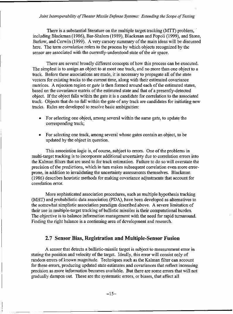
There is a substantial literature on the multiple target tracking (MTT) problem,including Blackman (1986), Bar-Shalom (1989), Blackman and Popoli (1999), and Stone,Barlow, and Corwin (1999). A very cursory summary of the main ideas will be discussedhere. The term correlation refers to the process by which objects recognized by thesensor are associated with the currently-understood state of the air space.
There are several broadly different concepts of how this process can be executed.The simplest is to assign an object to at most one track, and no more than one object to atrack. Before these associations are made, it is necessary to propagate all of the statevectors for existing tracks to the current time, along with their estimated covariancematrices. A rejection region or gate is then formed around each of the estimated states,based on the covariance matrix of the estimated state and that of a presently-detectedobject. If the object falls within the gate it is a candidate for correlation to the associatedtrack. Objects that do no fall within the gate of any track are candidates for initiating newtracks. Rules are developed to resolve basic ambiguities:
"* For selecting one object, among several within the same gate, to update thecorresponding track;
"* For selecting one track, among several whose gates contain an object, to beupdated by the object in question.
This association logic is, of course, subject to errors. One of the problems inmulti-target tracking is to incorporate additional uncertainty due to correlation errors intothe Kalman filters that are used to for track estimation. Failure to do so will overstate theprecision of the predictions, which in turn makes subsequent correlation even more error-prone, in addition to invalidating the uncertainty assessments themselves. Blackman(1986) describes heuristic methods for making covariance adjustments that account forcorrelation error.
More sophisticated association procedures, such as multiple hypothesis tracking(MHT) and probabilistic data association (PDA), have been developed as alternatives tothe somewhat simplistic association paradigm described above. A severe limitation oftheir use in multiple-target tracking of ballistic missiles is their computational burden.The objective is to balance information management with the need for rapid turnaround.Finding the right balance is a continuing area of development and research.
2.7 Sensor Bias, Registration and Multiple-Sensor Fusion
A sensor that detects a ballistic-missile target is subject to measurement error instating the position and velocity of the target. Ideally, this error will consist only ofrandom errors of known magnitude. Techniques such as the Kalman filter can accountfor these errors, producing updated state estimates and covariances that reflect increasingprecision as more information becomes available. But there are some errors that will notgradually dampen out. These are the systematic errors, or biases, that affect all
-15-
Joint Interoperability of Theater Missile Defense Systems: Extending the Scope of Testing
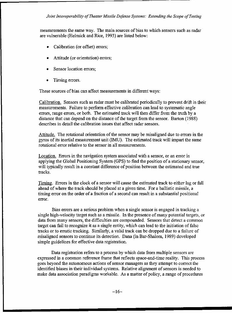
measurements the same way. The main sources of bias to which sensors such as radarare vulnerable (Helmick and Rice, 1993) are listed below:
"* Calibration (or offset) errors;
"* Attitude (or orientation) errors;
"* Sensor location errors;
"* Timing errors.
These sources of bias can affect measurements in different ways:
Calibration. Sensors such as radar must be calibrated periodically to prevent drift in theirmeasurements. Failure to perform effective calibration can lead to systematic angleerrors, range errors, or both. The estimated track will then differ from the truth by adistance that can depend on the distance of the target from the sensor. Barton (1988)describes in detail the calibration issues that affect radar sensors.
Attitude. The rotational orientation of the sensor may be misaligned due to errors in thegyros of its inertial measurement unit (IMU). The estimated track will impart the samerotational error relative to the sensor in all measurements.
Location. Errors in the navigation system associated with a sensor, or an error inapplying the Global Positioning System (GPS) to find the position of a stationary sensor,will typically result in a constant difference of position between the estimated and truetracks.
Timing. Errors in the clock of a sensor will cause the estimated track to either lag or fallahead of where the track should be placed at a given time. For a ballistic missile, atiming error on the order of a fraction of a second can result in a substantial positionalerror.
Bias errors are a serious problem when a single sensor is engaged in tracking asingle high-velocity target such as a missile. In the presence of many potential targets, ordata from many sensors, the difficulties are compounded. Sensors that detect a commontarget can fail to recognize it as a single entity, which can lead to the initiation of falsetracks or to erratic tracking. Similarly, a valid track can be dropped due to a failure ofmisaligned sensors to continue its detection. Dana (in Bar-Shalom, 1989) developedsimple guidelines for effective data registration.
Data registration refers to a process by which data from multiple sensors areexpressed in a common reference frame that reflects space-and-time reality. This processgoes beyond the autonomous actions of sensor managers as they attempt to correct theidentified biases in their individual systems. Relative alignment of sensors is needed tomake data association paradigms workable. As a matter of policy, a range of procedures
-16-

Joint Interoperability of Theater Missile Defense Systems: Extending the Scope of Testing
can be used to align sensors in a multi-sensor tracking system to set system clocks,determine sensor locations, etc.
Data registration can also be built into the tracking software to identify biases thathad not been removed previously. Methods have been developed using the Kalman filter(Helmick and Rice, 1993), and more recently, using neural networks (Karniely andSiegelmann, 2000). The latter, in particular, is computationally intensive and requires asubstantial quantity of data. On the other hand, data registration should be viewed as anongoing process, rather than a technique to be employed once threatening targets havebeen detected. Kamiely and Siegelmann found that their neural network registrationmethod successfully detected complex bias patterns that a Kalman filter was unable todetect.
-17-

Joint Interoperability of Theater Missile Defense Systems: Extending the Scope of Testing
3. Interoperability and Department of DefenseMessage Standards
A theater-area missile defense (TMD) family of systems (FoS) with TADIL A/Bor TADIL J messaging is expected to conform to standards:
"* MIL-STD-601 lB (henceforth abbreviated 60111B) for TADIL A/B,
"* MIL-STD-6016A (henceforth abbreviated 6016A) for TADIL J.
60111B addresses missile tracking only in the context of reporting air tracks. TADIL A/Bis, at best, a minimal platform for meeting the composite tracking requirements of a TMDFoS. In contrast, TADIL J provides specific messaging resources to meet theserequirements, and has been designated for use over the Joint Data Network (JDN) tocommunicate missile tracks between participants in a TMD FoS. This section will focusmainly on 6016A, because TADIL J is the messaging platform that was designed forachieving interoperability within a TMD FoS.
3.1 TADIL Message Standards
The message standards for TADIL A/B and TADIL J address similar issuespertaining to interoperability of a TMD FoS, but the former is less specific in manyrespects. The important issue of track quality (TQ) number reporting is illustrative. TheTQ number is an assessment, by a participating system, of its reliability in estimating theposition and velocity of a possible ballistic missile track. 6016A gives detailedinstructions on how this quantity is to be calculated (on a 0-15 scale), but 6011B offersno instructions other than that the TQ number is to represent reliability on a scale where0 = lowest and 7 = highest. Moreover, 6016A provides for the reporting of covarianceinformation whereas 601 1B does not.
Compliance with either message standard should be viewed as necessary, but notsufficient conditions for achieving interoperability. Coherent communication isnecessary for systems to work together, but unless what is communicated is bothsufficient and correct interoperability will not be achieved. This especially applies tojoint surveillance of an air space that may contain high-velocity ballistic missiles.
3.2 Track Quality and Reporting Responsibility
In a multi-sensor environment there is a need to organize data processing so thataccuracy, timeliness, and proper management of communication resources is achieved.But these are conflicting goals. An alternative concept of multi-sensor tracking is to haveeach sensor or system report its information to a central processor at every reportinginterval, which then updates existing tracks, initiates new tracks, and drops obsolete or
-18-

Joint Interoperability of Theater Missile Defense Systems: Extending the Scope of Testing
erroneous tracks based on all available information. In theory, a "composite" tracker ofthis kind should be able to achieve greater accuracy than to have one system report on atrack at any given time, and to have all systems process data autonomously. But thecommunication resources that the former would require exceeds what is contemplated inthe TADIL message standards, and its workability in concept is not assured.
6016A conceives of joint tracking where only one joint user (JU) officially reportson a track at any given time. The reporting JU is assigned reporting responsibility (R2)for the track. It is the responsibility of the JU with R2 to perform the calculations neededto update the track with new information from the previous to the current time period,and to report the outcome to all other JUs in the network participation group (NPG). R2
is awarded on the basis of "competition" between different JUs that are capable ofreporting on a track. The JU that can report positional and velocity information with thegreatest accuracy, according to its own claim, is assigned R2.
The assignment of R2 is based on a track quality (TQ) number that a JU calculatesand transmits to express the reliability of its information about the track. 6016A offersspecific instructions on how a TQ number is calculated. It is derived from a quantity Bthat based on the 6 x 6 covariance matrix of three-dimensional position and velocitymeasurements (in ECEF coordinates):
3
B = J-[Var(rj)+A2,Var(*j)]j=1
where r. is one of the three-dimensional position coordinates estimated by the sensor, *j
is the corresponding velocity coordinate, and A, is a time increment, taken to be 6
seconds by default (6016A, p. 4-200). The quantity B is referred to a "look-up" table(6016A, p. 5.1-752) to determine the TQ number.
In some of its interoperability testing the JITC has observed message streams thatcontain both TADIL A/B and J messages. This mixture presents the FoS with the need tocompare TQ numbers that were derived using different scales and different criteria.
3.2.1 Factors That Affect The Accuracy of TQ Numbers
Despite its more careful formulation, there are a number of reasons why TQnumbers reported on TADIL-J may fail to reflect true reliability:
1. Data registration was either neglected or not effectively executed, so thatsubstantial sensor bias remains;
2. Covariance matrices do not accurately reflect random measurement errors ofthe sensor;
-19-

Joint Interoperability of Theater Missile Defense Systems: Extending the Scope of Testing
3. Covariance matrices do not accurately reflect process noise in the dynamic statemodel used to describe motion of the missile;
4. The covariance matrices do not accurately reflect correlator errors;
5. The JU did not follow the guidelines for calculating the TQ number.
Experience with TMD FoS testing at the JITC suggests that any or all of these problemsmay be present.
3.2.2 Effect of TQ Number Inaccuracy on Interoperability
Under the TQ-number concept for assigning R2 even one JU that overstates itsaccuracy can degrade the system. Data registration, which is a basic requirement of anymulti-sensor tracking system, must be rigorously observed if TQ numbers are to be usedin the manner suggested by the TADIL message standards. There is no agent under thisconcept that can down-weight or disregard data from a sensor that appears to bemisaligned.
Data registration will not be perfect. The bias adjustments themselves will beprone to error, mobile sensors will move, and sensors may drift gradually intomiscalibration over time. At times when R2 shifts from one sensor to another, spatialoffsets in the track of some order of magnitude will occur. Depending on the magnitudeof these offsets, the network interface will display tracks that "criss-cross" in physicallyunexplainable ways, display multiple tracks for the same object, and drop valid tracksprematurely. Neglected or poorly followed data registration procedures will increase themagnitude of the offsets and exacerbate these-problems.
Even in the absence of registration errors, the association of sensor information totracks will be subject to errors due to measurement uncertainty. During correlation,statistical "gating" criteria similar to hypothesis testing are used to determine whichexisting tracks (propagated to the current time) match a sensor's measurements. If noneof the tracks match, a new track may be initiated. Similarly, if a track does not match toat least one sensor's measurements, it may be dropped. Random errors in sensormeasurements, and process noise in the missile dynamics, make gating an imperfectprocess. Thus, false tracks and dropped tracks can be expected to occur under the TQ-number concept even under the best of circumstances. The questions that should beasked are, what are the lowest erroneous tracking rates that can be achieved, and can theFoS under consideration achieve these rates?
-20-
Joint Interoperability of Theater Missile Defense Systems: Extending the Scope of Testing
3.3 Quantitative Requirements for Space-Track Messaging
601 lB requires that a JU report the TQ number, position, and velocity of a trackusing TADIL A/B messaging. For space-track TADIL J messaging, 6016A provides forthe reporting of a larger set of track-related quantities, some of which are required, butothers are subject to ambiguous reporting requirements.
3.3.1 Units of Measurement
Both TADIL A/B and TADIL J use English units for measuring distance, but theircoordinate systems are different. TADIL A/B uses "flat Earth" topocentric coordinatescentered at a System Coordinate Center (SCC). The positional measurements are East,North, and Height oriented. East and North are measured in data miles, in increments of¼ data mile (1,500 feet). A maximum displacement of 511.75 data miles (581.5 standardmiles) can be reported in either direction from the SCC in the East and North coordinates.Velocity is measured in data miles per hour, in increments of 28 1/8 dm/hr, in the Eastand North directions. A maximum absolute velocity of 3,571 7/8 dm/hr (about 1.13standard miles per second) can be reported. Height is measured in feet, in increments of500 feet. A maxium height of 127,000 feet (appx. 24 standard miles) can be reported.There is, however, no provision for reporting velocity in height. This somewhat limitsthe scope of missile reporting that is possible on TADIL A/B.
TADIL J uses ECEF coordinates based on the WGS-84 Earth Model for an oblateEarth. All coordinates are measured in feet, in increments of 10 feet. A maximumdisplacement of 41,943,030 feet (7,944 miles) from the center of the earth, in anycoordinate direction, can be reported. Velocities are measured in feet per second, inincrements of 3.33 feet per second. A maximum absolute velocity of 27,276 ft/sec can bereported in any coordinate direction. Since the radius of the earth is approximately 3,963miles virtually any theater-wide ballistic missile can be tracked on TADIL J.
A mixture of coordinate systems and measurement units results if a TMD FoS hasboth TADIL A/B and J messaging. Although the conversions are not difficult to make,they present an opportunity for error. Additionally, a FoS concept that includes alliednations' assets should be aware of metric-English unit conversion issues. A confusion offeet with meters can sometimes produce seemingly plausible values.
3.3.2 Covariance Reporting
TADIL A/B messaging requires the reporting of the track number (TN), time, TQnumber, and positional information in the units described above2 . It also requires thereporting of velocity, but only for the surface (East, North) coordinates. There is noprovision for reporting variances, covariance matrices or other measures of statistical
2 Other information is reported as well, on both TADIL A/B and TADIL J, but not covered here if it does
not pertain to obtaining an accurate description of the motion of the tracked object.
-21-
Joint Interoperability of Theater Missile Defense Systems: Extending the Scope of Testing
accuracy, or other quantitative attributes of a missile trajectory (e.g., the impact point).The only information about the missile vehicle is a data field that indicates whether or notthe track is a missile.
TADIL J, by contrast, provides for all of the above, plus complete velocityinformation, covariances, the impact point prediction (and its covariance matrix), thelaunch-point estimate (and its covariance matrix), the missile type (from an extensive listof known types), and the ballistic coefficient. Some of these quantities must be reportedevery time, others only under specified conditions, while others are subject to ambiguousreporting requirements. 6016A is particularly unclear about when the position-velocitycovariance matrix must be reported. Perhaps as a result, the JITC has observed thatcovariance matrices are not consistently reported in TMD FoS testing. Without thecovariance matrix it is difficult to compare stated accuracy to actual performance, toverifyr that the TQ number was calculated properly, and difficult for another JU tocorrelate its sensor data to the registry of existing tracks.
If a JU with R2 on a track does not report covariance informnation in the J3.6message, another JU can request this information by issuing a J7. 1 message with thecovariance indicator set. A "provide only upon request" policy (if one exists) may reflectan information management strategy to minimize laborious data processing andmessaging. If this is the case, the benefits should be reviewed in light of the difficultiesthat not having this information creates. To wait for a request before transmittingcovariance information adds to the message stream and delays the resolution of trackingissues through data processing.
6016A is also unclear on when the full 6 x 6 matrix should be reported, or when aJU may report two 3 x 3 covariance matrices representing the positon and velocityseparately. The latter is appropriate only if it is known that position and velocityestimates are uncorrelated. The validity of this assertion is doubtful. In Kalman filterstate equations, position and velocity are coupled. Additionally, sensors that use Dopplerto measure velocity are subject to error sources that affect Doppler, range, and anglemeasurements simultaneously (see section 2.2). The small savings in processing timeand messaging that may be achieved by a partial transmission of covariance informationshould be weighed against the consequences of making what is a potentially falseassumption.
Under 6016A a covariance matrix is supposed to reflect all known sources oferror, including random error and systematic error (bias). Systematic error arises fromsensor measurement bias and from registration errors. Random error is a part of theuncertainty of sensor measurement, and it also arises from process noise in the dynamicsof missile motion. An additional source of error is due to the use of a correlatoralgorithm. Correlator error refers to uncertainty in assigning sensor data to tracks.
Standard usage of the term "covariance matrix" refers to the random errorcomponent only. If the Kalman filter is used, this matrix is updated in real time alongwith the state vector using a recursion relationship. The resulting covariance matrix
-22-
Joint Interoperability of Theater Missile Defense Systems: Extending the Scope of Testing
reflects both random error and process noise at any given time. Bias is sometimesincorporated into a covariance matrix by treating it as a "random effect." However, if thebias is known or carefully estimated, it is usually preferable to calibrate rather than toadjust the covariance matrix. Random effects are not "independent" across a series ofmeasurements, which makes it difficult to interpret confidence ellipses and predictionregions that reflect their influence. Similarly, correlator errors are difficult to estimate,and are not included in the usual concept of a covariance matrix. Nonetheless, correlatorerrors do increase the uncertainty, and their existence should be reflected.
Because 6016A does not offer guidance on how all sources of error should bereflected in a covariance matrix, it is likely that not all JUs will estimate it the same way.Covariance matrices, and the TQ numbers derived from them, can be expected to varyamong JUs for this reason alone.
In TADIL J messaging a covariance matrix is not transmitted directly. 6016Arequires that the 6 x 6 covariance matrix of position and velocity, denoted P, bemathematically encoded before it is communicated to other JUs. The encoding procedureis described in section 4.4.6.9 of the standard, and briefly summarized below:
1. Extract the diagonal of P (the variances), and take their square roots (the rootvariances).
2. Use the root variances to scale P to a 6 x 6 correlation matrix C.
3. Precompensate C by multiplying its off-diagonal elements by a number slightlysmaller than one (1 - 2-22 ) to preserve its positive definiteness under roundofferror. Call this new matrix Cp.
4. Find the Cholesky (root) matrix, U, of Cp. The Cholesky matrix is a 6 x 6 matrixwith zeros below the main diagonal (i.e., at most 21 of the 36 entries of Uare notzero).
5. Take the (base 10) logarithms of the root variances.
6. Transmit the log-root variances and sufficient information from U to allowreconstruction of P by the receiver. This requires the transmission of 165 bits inthe J3.6 message.
These steps are reversible: given the Cholesky matrix and the logarithms of the rootvariances it is possible to reconstruct P.
If only partial covariance information is transmitted, encoding is appliedseparately to the upper 3 x 3 submatrix of P that relates to positional coordinates, and tothe 3 x 3 lower submatrix of P that relates to velocity coordinates. As discussed earlier,the use of partial covariance information assumes that positional and velocity estimatesdo not cross-correlate.
-23-
Joint Interoperability of Theater Missile Defense Systems: Extending the Scope of Testing
The following points can be made about the encoding procedure:
1. Transmitting the Cholesky matrix does not conserve bandwidth. If the elementsof Cp above the main diagonal are transmitted instead of what is transmitted on U,the same number of bits (165) is required3 .
2. The benefit of transmitting Cholesky matrices should be clearly defined. Kalmanfilter propagation at the JU level may be able to use Cholesky matrices toadvantage, but only if software is designed accordingly. If JUs reconstruct theoriginal covariance matrix, any advantage is lost. 6016A does not address thispoint, and even appears to imply that the reconstruction will be performed.
3. The encoding procedure should be evaluated as a whole. This should be donewith respect to both numerical accuracy, and computational burden, at both thetransmitter and receiver ends. This is further addressed in section 3.3.3 below.
The transmission of complete covariance information in a numerically efficientand sound manner is an interoperability issue. Adding to the computational burden ofJUs without tangible benefit reduces response time, and imparts numerical error, both ofwhich make tracking high-velocity objects a greater challenge.
3.3.3 About Numerical Accuracy
Each covariance element that is transmitted in the J3.6 TADIL J message isassigned 10 bits for its absolute value, plus one bit for a sign (+1 or -1) if needed.Numerically, 10-bit coding is somewhat "coarse" in that it allows only 1,024 distinctnumbers to be represented. For an individual number, this may be good enough as anapproximation, but in the context ofjoint tracking it can pose several problems. Oneproblem is that covariance matrices may become ill-conditioned. Another problem is thatnumerical error may build up over repeated application of the Kalman filter. Numericalerror propagation is recognized as a significant problem in usage of the Kalman filter(Grewal and Andrews, 1993).
It is doubtful that the precompensation described in section 3.3.2 will have mucheffect on numerical stability. Applying a multiplicative factor of 1 - 2-22 will make littleor no difference in how a covariance matrix is encoded with 10-bit digitization.
3 The precompensated correlation matrix Cp is symmetric and has ones on its main diagonal, so only the 15elements above the main diagonal are informative.
-24-
Joint Interoperability of Theater Missile Defense Systems: Extending the Scope of Testing
3.3.4 Launch-Point Estimate Reporting
601 6A assigns R2 for the launch point in a different manner than for space tracksin general. Only sensors that detect the object shortly after launch would normally beeligible for R2. The standard further states that "back azimuth" should be used toestimate the launch point. But as noted in section 2, simple back-extrapolation schemesare not regarded as very reliable for this task. Missile motion dynamics over one orseveral boost phases, followed by transition into a ballistic phase, makes reversing thetrajectory a difficult problem. Recent research by Li et al. (1999) may offer a betterapproach. Their maximum likelihood (ML) estimation technique also provides anestimated covariance matrix for the true launch point.
3.3.5 Impact-Point Prediction Reporting
601 6A assigns R2 for the impact point to the same JU that has R2 for the spacetrack. The impact point can be estimated by integrating the dynamic state model (withoutprocess error) forward in time until impact with the earth is achieved. However, theprediction covariance matrix for the impact point should reflect two sources ofvariability:
*Error in estimating the position and velocity of the track, given by the covariancematrix reported under TADIL J;
*Process noise, or variability in the dynamics of motion.
There is an implicit assumption that the sensors are unbiased: if they are not, then theprediction covariance matrix may fail to "localize" the impact point in a high-probabilityelliptical region.
The JITC has often observed that, when R2 shifts from one JU to another, not onlydo the impact-point predictions change, the 95 percent probability ellipses also change,both in shape and size. This may be the result of different sensor biases, or the use ofdifferent techniques to predict the impact point and estimate its covariance matrix.Sensor biases are better addressed through calibration and data registration proceduresthan by attempting to account for them in covariance matrices. If a JU knows its sensorbiases, it should try to remove them; if a JU does not know its sensor biases, it is not in agood position to account for their effects.
Accounting for process noise in the prediction covariance matrix poses a problemfor joint tracking under TADIL J. Consider a JU that has had R' on a track for a periodof time. From its repeated measurements and use of the Kalman filter, the iii obtainedthe covariance matrix of the current state estimate and the covariance matrix of theprocess noise. This enables the JU to estimate both the impact point and its associatedprediction covariance matrix. Now suppose that a different JU assumes R2. It continuestracking using its own sensor measurements, and the Kalman filter outputs of its
-25--
Joint Interoperability of Theater Missile Defense Systems: Extending the Scope of Testing
predecessor. But, the process noise covariance matrix was not transmitted. BecauseTADIL J makes no provision for the transmission of this "other" covariance matrix, itmust be estimated anew each time R 2 changes.
This represents a loss of information to the network, and it is disadvantageous forjoint tracking. Every time R2 changes and the process noise covariance matrix is re-estimated, it is done so using only a small number of state-equation residuals, whichmakes the estimate unreliable. If the process noise is substantial, this can lead to visualdisruption in the 95% prediction regions for the impact point at the times when R(2
changes.
3.4 Correlation Under TADIL Message Standards
Both 601 lB and 6016A discuss correlation, although 6016A covers this subject ingreater detail. Under both standards it is the obligation of the JU to correlate its sensordata to the existing registry of tracks. If no association can be made to an existing track,the JU may initiate a new track for the object. 6016A does not require that one, specificcorrelator be used by all JUs, or even that the correlator methodology be the same.
The correlation process can be briefly described as follows:
1 . Each existing track has a time tag, a position-velocity state vector (six-dimensional), and a position-velocity covariance matrix (6 x 6, see section 3.2.2above).
2. If a JIJ has sensor data at the "current" time to be correlated to the existingregistry, then that JU must propagate each of the state vectors and covariancematrices forward to the current time, using standard Kalman filter techniques 4.
3. The state and sensor covariance matrices are combined 5 to form "gating" regions.All tracks in the registry whose gates contain the sensor data are eligible forassociation. If there is more than one such track, association logic (e.g. nearestneighbors) is used to choose the "best" match.
4. If no track in the registry contains the sensor data in its gate, then a new track maybe initiated in the registry.
Step 2 of this process requires full, and reliable, covariance information from allJUs that have R on a track. Without it, another JU cannot properly update the statevectors or form the necessary gating regions. This again points to transmission of thecovariance matrix as an interoperability issue.
4 In practice, some tracks may be ruled out quickly and not require propagation, thus reducing thecomputational burden of the JU.5 The combination must occur in either the coordinate system of the sensor or that of the state vector. Somesensors, such as IR, may not provide the measurement equivalent of a full six-dimensional state vector.
-26-

Joint Interoperability of Theater Missile Defense Systems: Extending the Scope of Testing
601 6A does not offer specific, quantitative guidelines on correlation. The JUsmay use different correlators that operate under different criteria for gating and matchingsensor data to tracks. It is possible, for example, that different tradeoffs between thegeneration of false tracks and the dropping of valid tracks may be in place simultaneouslythroughout the FoS.
3.5 Data Registration Under TADIL Message Standards
Both 601 lB and 6016A recognize the importance of having sensors and theirmeasurements properly aligned with each other. The term data registration is used herein the same sense as section 2.7: it refers to a process in which a sensor's location andorientation are correctly determined, its measurement biases are removed throughcalibration, its clock is set, and any remaining relative biases between sensors aredetected (and removed) by means of a data analysis procedure6 . In 601 6A four types oferror that data registration is designed to address are identified:
1. Geodetic position errors
2. Sensor errors
3. Data processing errors
4. Remote interface unit (111) registration errors.
Table 4.1-5 (6016A, p. 4-18) summarizes these errors, and Figure 4.1-3 (6016A, p. 4-23)gives a diagram of the data registration process. 601 6A provides acceptable errortolerances for JUs to use as data registration standards.
The data registration activities described in 601 6A can be best described asautonomous: each JU is responsible for its own compliance, but compliance is notmonitored. There is no messaging from a JU to the network concerning its dataregistration activity. This activity is also to be carried out "with minimal interference to,or curtailment of, normal data system operation." (6016A, p. 4-2 1). Some interactivedata registration issues are covered under precise participant location and identification(PPLI) activity (section 4.3 of 6016A). PPLI addresses synchronization of the JUsrelative to each other, with respect to system timing and relative navigation. TADIL Jprovides message space to conduct these PPLI activities.
6 TeTADIL message standards define sensor registration as one activity under the scope of dataregistration, as is done here. See section 4.2.2 of 601 1B and section 4.1.4 of 6016A. In the scientificliterature, sensor registration usually refers to the entire scope of data registration activity.
-27-
Joint Interoperability of Theater Missile Defense Systems: Extending the Scope of Testing
3.5.1 The Data Registration Imperative
Although the TADIL message standards recognize the importance of dataregistration, few of its facets are included in network messaging. If a JU transmits datawith registration errors, which are unlikely to be reflected in TQ numbers, the networkwill not be aware of this and interoperability will be degraded. In addition, the treatmentof data registration as an item of secondary importance may promote its neglect, to thedetriment of interoperability.
Effective data registration requires more careful articulation than what is providedin the TADIL message standards. Consider a TMD FoS that operates over a certaingeographic area. Each of its sensors must be calibrated on an ongoing basis. Mobilesensors must recalculate their locations. But, corrective procedures will be successful toonly a certain extent. Relative biases will remain between sensors due to errors inperforming calibration, or neglect of calibration, by even one sensor. Because of thedecentralized nature of data processing in the JDN, data registration should be made anintegral part of TMD FoS operations.
3.5.2 Integrating Data Registration Into Operations
There is a good argument to be made that a TMD FoS cannot be madeinteroperable unless the network exchanges information on data registration. To bringthis about would require modification of the operational concept of a TMD FoS that usesTADIL J messaging over a JDN. Integrating data registration into operations would haveseveral tangible benefits:
"* Interoperability problems that arise from registration errors would be traceable totheir cause;
"* Real-time data registration procedures would be made feasible;
"* Systems would be aware that data registration procedures must be integrated intotheir operations.
In the current concept of interoperability testing, the biases of each system can beassessed post facto by comparing the content of track messages to "truth" trajectories.This type of analysis is important, but it is retrospective. Biased tracks can enter thesystem without detection, which degrades interoperability.
On an operational level, integrating data registration into network messagingwould require that a "dummy object", with a trajectory known to all JUs, be provided forthe systems' sensors to track. Ideally, this would be a physical object (e.g., an aircraft,UAV, or satellite), but a simulated object may be at least partially adequate. Themessage stream would contain each JU's track of the dummy object in addition to itsregular surveillance tracks.
-28-
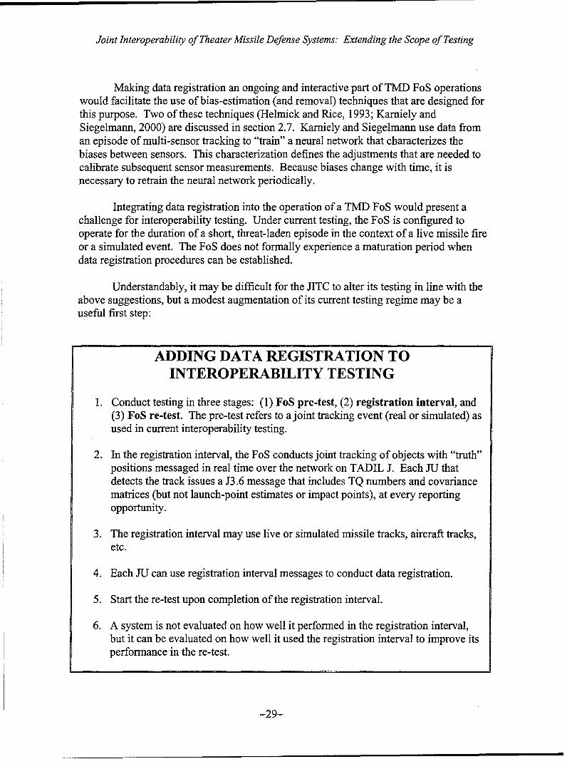
Joint Interoperability of Theater Missile Defense Systems: Extending the Scope of Testing
Making data registration an ongoing and interactive part of TMD FoS operationswould facilitate the use of bias-estimation (and removal) techniques that are designed forthis purpose. Two of these techniques (Helmick and Rice, 1993; Karniely andSiegelmann, 2000) are discussed in section 2.7. Kamiely and Siegelmann use data froman episode of multi-sensor tracking to "train" a neural network that characterizes thebiases between sensors. This characterization defines the adjustments that are needed tocalibrate subsequent sensor measurements. Because biases change with time, it isnecessary to retrain the neural network periodically.
Integrating data registration into the operation of a TMD FoS would present achallenge for interoperability testing. Under current testing, the FoS is configured tooperate for the duration of a short, threat-laden episode in the context of a live missile fireor a simulated event. The FoS does not formally experience a maturation period whendata registration procedures can be established.
Understandably, it may be difficult for the JITC to alter its testing in line with theabove suggestions, but a modest augmentation of its current testing regime may be auseful first step:
ADDING DATA REGISTRATION TOINTEROPERABILITY TESTING
1. Conduct testing in three stages: (1) FoS pre-test, (2) registration interval, and(3) FoS re-test. The pre-test refers to a joint tracking event (real or simulated) asused in current interoperability testing.
2. In the registration interval, the FoS conducts joint tracking of objects with "truth"positions messaged in real time over the network on TADIL J. Each JU thatdetects the track issues a J3.6 message that includes TQ numbers and covariancematrices (but not launch-point estimates or impact points), at every reportingopportunity.
3. The registration interval may use live or simulated missile tracks, aircraft tracks,etc.
4. Each JU can use registration interval messages to conduct data registration.
5. Start the re-test upon completion of the registration interval.
6. A system is not evaluated on how well it performed in the registration interval,but it can be evaluated on how well it used the registration interval to improve itsperformance in the re-test.
-29-
Joint Interoperability of Theater Missile Defense Systems: Extending the Scope of Testing
This augmentation should be viewed as a demonstration project, rather than as acomprehensive data registration procedure of the type described earlier. Nonetheless,each XI would acquire information that it could use to reduce its registration errors.There are many potential variations of this three-tiered testing concept. The JITC shoulddetermine which variation is the most appropriate for the FoS that is under test.
-30-
Joint Interoperability of Theater Missile Defense Systems: Extending the Scope of Testing
4. Joint Interoperability Testing: Current Approaches
Over the last several years the JITC has conducted interoperability testing ofTMD FoS based on the JDN concept, in which TADIL J messaging is the centralcommunications platform. The JITC has also conducted interoperability certificationtesting of the PATRIOT Advanced Capability Level 3 (PAC-3) system relative to thesame concept. Testing to date has emphasized the following three of five identifiedlayers: (1) physical layer, (2) information layer, and (3) functional layer. These layersare hierarchical, in the sense that functionality cannot be achieved without a workableinformation layer, nor can information integrity be assured without the physical layer tosupport it.
The material addressed in this report assumes that testing has proceeded beyondthe physical layer to the information and functional layers. Discussion of covariancematrix transmission in section 3.4 identified interoperability issues in the informationlayer. In the functional layer interoperability is addressed in topics such as the validity oftracking algorithms, the TQ-number concept, correlator performance, and dataregistration.
The JITC has recognized that interoperability testing and certification under theJoint Composite Tracking Network (JCTN) concept may be conducted at a future time.JCTN, which was still under development at the time this report was written, refers to "ajoint telecommunications network and processing capability to enable composite trackingamong joint, heterogeneous mixes of sensors, and to support appropriate levels ofcooperative engagement of targets by weapons systems."7 JCTN stands in contrast toJDN in several important respect, the most important of which is that, under JCTN, eachsystem must process tracking information using "the same algorithms running onprocessors with virtually identical architectures."8 It is likely that JCTN will requiremessage standards that are neither a subset nor a superset of 6016A in order to support it.
JCTN is being designed to overcome some of the interoperability problems at thefunctional level that have been exhibited in TMD FoS testing under the JDN concept. Itssuccess remains to be proven, although it is modeled on the U.S. Navy's well-receivedCooperative Engagement Capability (CEC) concept. In conjunction with thedevelopment of JCTN, performance metrics are also beiný developed and distributed toappropriate parties in the form of benchmarking software .
Most of the JCTN performance metrics are related to interoperability. Some ofthe metrics are similar in scope to what the JITC has been using in testing under the JDNconcept. It would be desirable to have a set of consistent metrics so that incrementalimprovements can be measured as TMD FoS concepts evolve. Comparisons can then bemade for a given FoS configured under JDN and JCTN.
7 Joint Composite Tracking Network (JCTN) Summary Tutorial, p. 3B.8 id., p. 4A.9 Version 1.08 of the JCTN Benchmarking Environment was released on June 5, 2000.
-31-
Joint Interoperability of Theater Missile Defense Systems: Extending the Scope of Testing
It is useful to review the benchmarking metrics that have been developed forJCTN (Rothrock and Drummond, 1999), which stress interoperability respects that are insome ways similar to those that the JITC has developed. The JCTN metrics arecalculated in benchmarking software that is integrated by the interfacing systems intotheir test articles. This integration allows the test articles to be treated as "black boxes,"to be judged by performance without the need to view source code. The JCTN conceptof uniformity between systems' software makes this integrated testing possible.
JCTN is not designed to operate under a R 2 concept based on TQ numbers. Forthis reason much of the testing that is done under the JDN concept (involving, e.g. R2
violations, TQ-number issues) has no analog under JCTN. None of the JCTN metricsaddress estimation of launch points or prediction of impact points, which are recognizedas important data in 6016A and by the JITC. Similarly, the integrated structure of JCTNsuggests the use of metrics that would not be applicable to JDN.
Table 4-1 below summarizes the JCTN benchmarking metrics, with comments ontheir relation to metrics that are used by the JITC in its TMD FoS testing. The metricsare calculated with respect to a set of scoring times that are randomly chosen from thebeginning to the end of the test event. The random selection of scoring times is designedto prevent "gaming" of the metrics. Some of the metrics require local trackinginformation that is not readily available under JDN, and others are closely tailored to theJCTN concept. Formulas for the JCTN benchmarking metrics can be found in Rothrockand Drummond (1999).
-32-
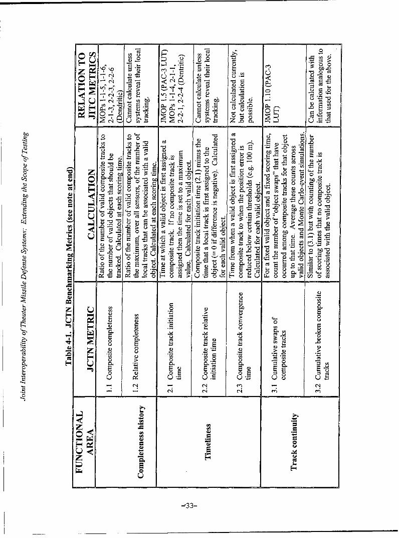
0
00 u0 ca
C- C.cc p=) C;
.. S Ee -E 0za)~C C)a.)0 0-ý
U>>
0 Cd > g =
0W0 0 - 4_
= 4.
0 0 0 >1 t =~C.= 2~E := o ~E 0-c
-. - 04 >0C .= -)c O 1)
00 cc 0Q~~r 0 0U~0 00~~U0
> U M ccn -0-
C.) >
.c4 -0 0 0
*.0.0c 0 C.0C C ~ ~ C
>) 0 ce -4 = - u4 L - -00 0.m j C
--S 75 ze
> o 0 0 bD _
CO 00
0 -' 0 0. z,
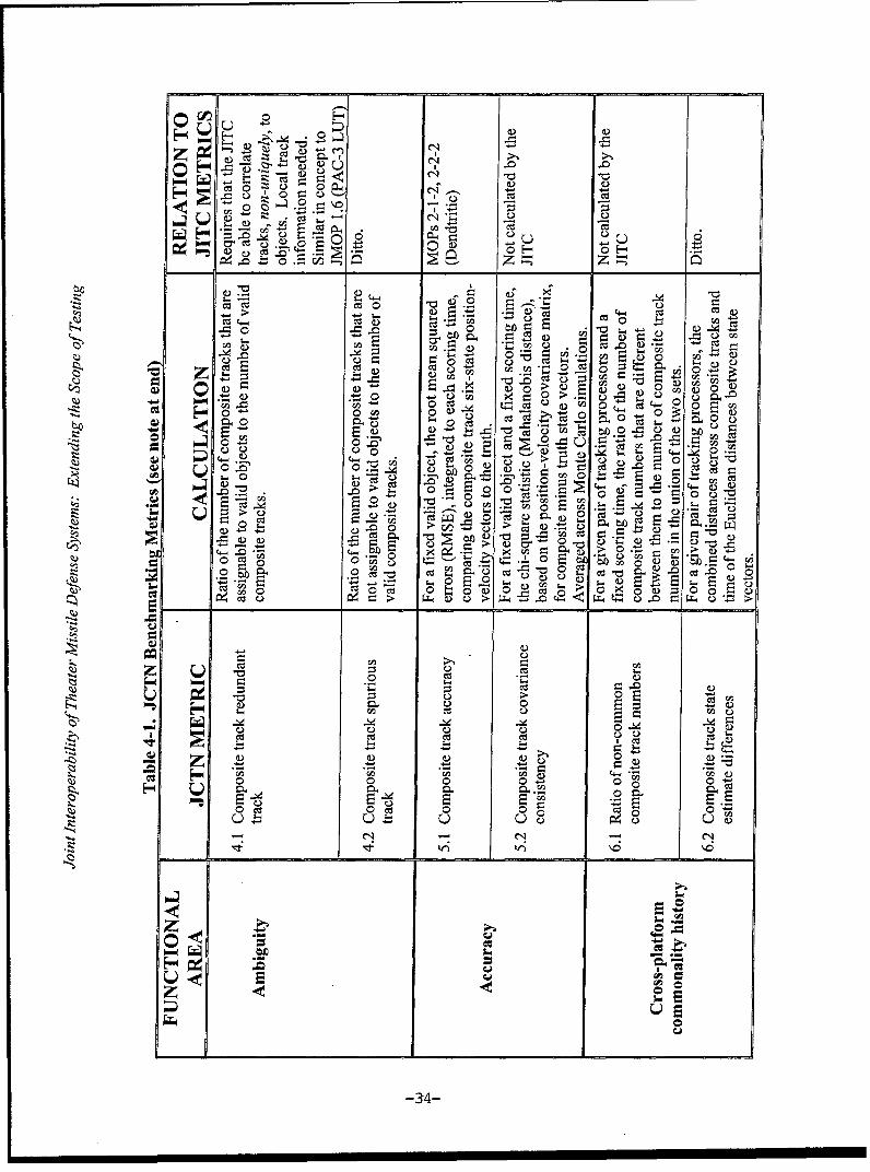
g 70
o z co .0 .
0 ~ -
En) C) w-t
" = ýQz cn w0 =H oH
~c.0.>
0.0 0z0 0
J40
0o -) cd rA cc
0. 0 :U)n a) t
Z -o o c_ 0
00 0 0U)Cc0U).
0~ 0E
Cd 0.30 0~ 0- L..~ ) U)$U)
E. C .0 0 0
O ct 0 c 00
U u ~uUc-
-34-
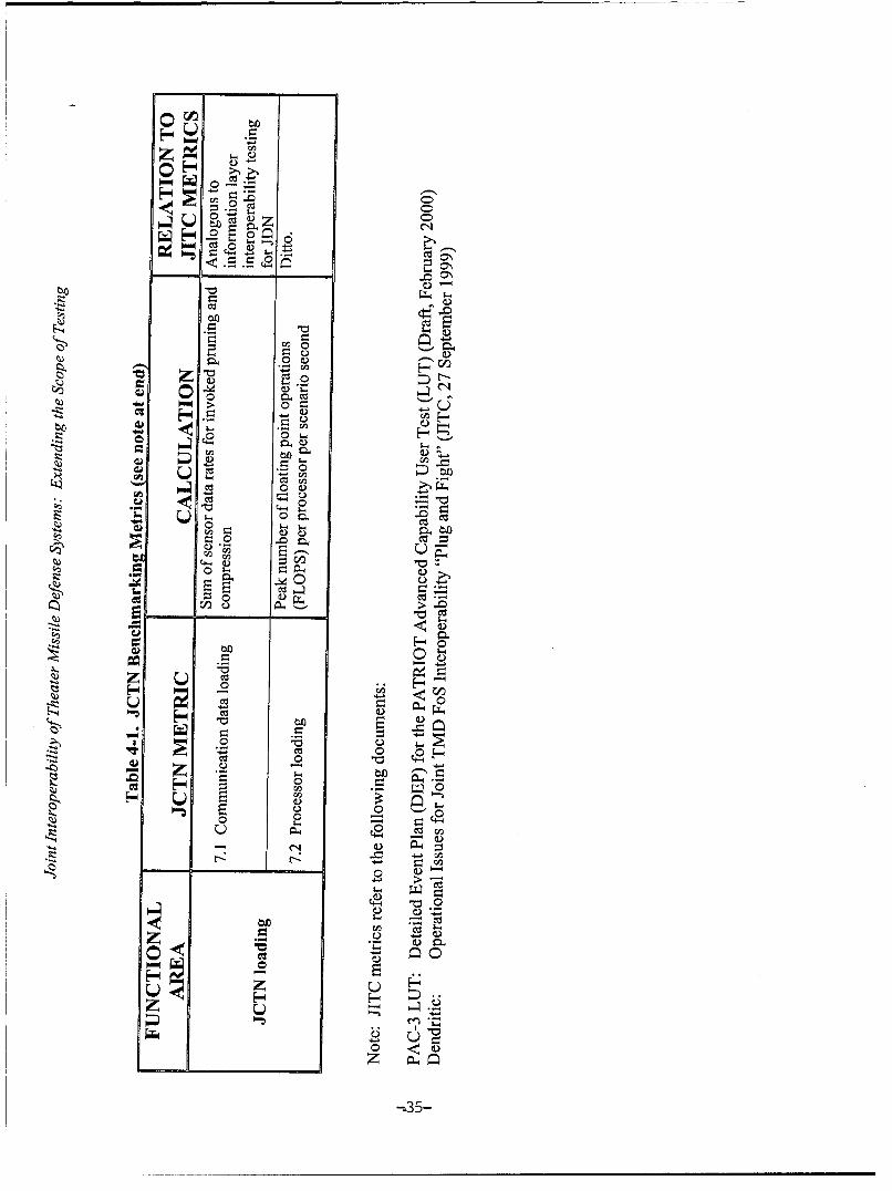
too
.0c
cj~ l
to~co
~ Cjd
0
0z czc
40.
IZS 0CC.)S4 Cl
C~ 0 0AC) C~ -~ C>
'~0 n
0
PLO0 ~ 20 0
0 - 350
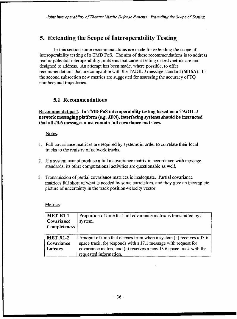
Joint Interoperability of Theater Missile Defense Systems: Extending the Scope of Testing
5. Extending the Scope of Interoperability Testing
In this section some recommendations are made for extending the scope ofinteroperability testing of a TMD FoS. The aim of these recommendations is to addressreal or potential interoperability problems that current testing or test metrics are notdesigned to address. An attempt has been made, where possible, to offerrecommendations that are compatible with the TADIL J message standard (6016A). Inthe second subsection new metrics are suggested for assessing the accuracy of TQnumbers and trajectories.
5.1 Recommendations
Recommendation 1. In TMD FoS interoperability testing based on a TADIL Jnetwork messaging platform (e.g. JDN), interfacing systems should be instructedthat all J3.6 messages must contain full covariance matrices.
Notes:
1. Full covariance matrices are required by systems in order to correlate their localtracks to the registry of network tracks.
2. If a system cannot produce a full a covariance matrix in accordance with messagestandards, its other computational activities are questionable as well.
3. Transmission of partial covariance matrices is inadequate. Partial covariancematrices fall short of what is needed by some correlators, and they give an incompletepicture of uncertainty in the track position-velocity vector.
Metrics:
MET-RI-1 Proportion of time that full covariance matrix is transmitted by aCovariance system.Completeness
MET-R1-2 Amount of time that elapses from when a system (a) receives a J3.6Covariance space track, (b) responds with a J7.1 message with request forLatency covariance matrix, and (c) receives a new J3.6 space track with the
requested information.
-36-
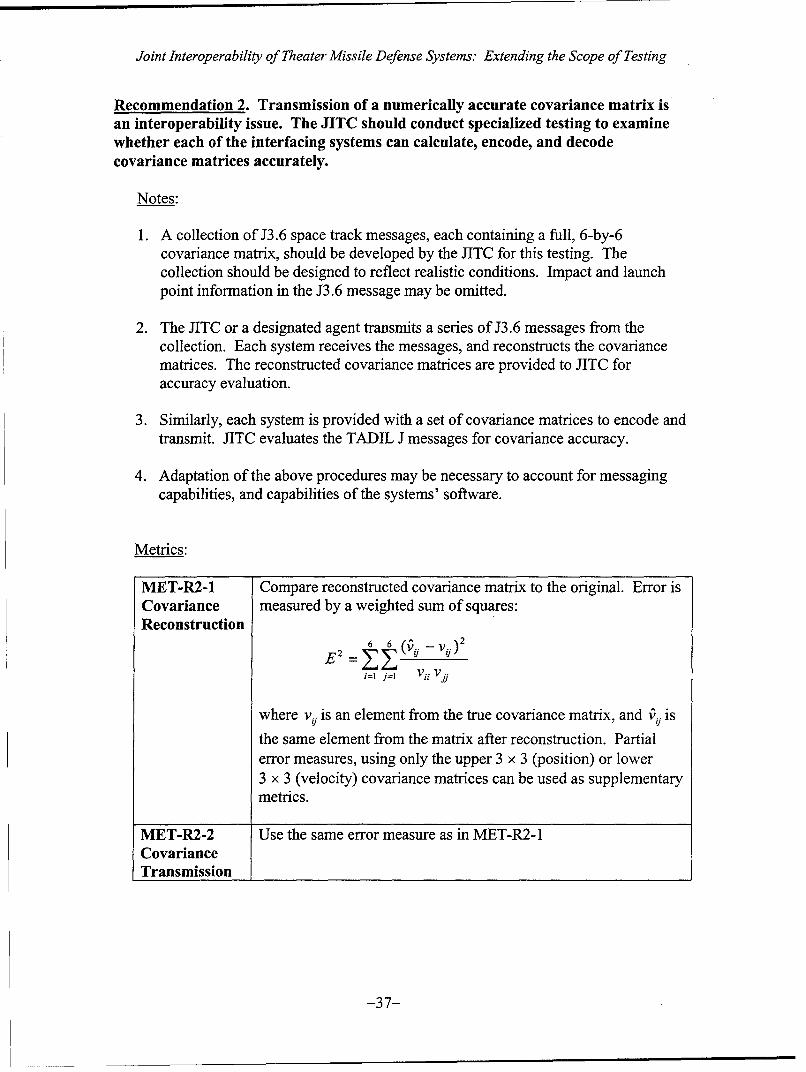
Joint Interoperability of Theater Missile Defense Systems: Extending the Scope of Testing
Recommendation 2. Transmission of a numerically accurate covariance matrix isan interoperability issue. The JITC should conduct specialized testing to examinewhether each of the interfacing systems can calculate, encode, and decodecovariance matrices accurately.
Notes:
1. A collection of J3.6 space track messages, each containing a full, 6-by-6covariance matrix, should be developed by the JITC for this testing. Thecollection should be designed to reflect realistic conditions. Impact and launchpoint information in the J3.6 message may be omitted.
2. The JITC or a designated agent transmits a series of J3.6 messages from thecollection. Each system receives the messages, and reconstructs the covariancematrices. The reconstructed covariance matrices are provided to JITC foraccuracy evaluation.
3. Similarly, each system is provided with a set of covariance matrices to encode andtransmit. JITC evaluates the TADIL J messages for covariance accuracy.
4. Adaptation of the above procedures may be necessary to account for messagingcapabilities, and capabilities of the systems' software.
Metrics:
MET-R2-1 Compare reconstructed covariance matrix to the original. Error isCovariance measured by a weighted sum of squares:Reconstruction
S:Z(') -vo) 2E2 6 6 (ý i
i=1 j=l Vii Vj.9
where vi. is an element from the true covariance matrix, and V•i. is
the same element from the matrix after reconstruction. Partialerror measures, using only the upper 3 x 3 (position) or lower3 x 3 (velocity) covariance matrices can be used as supplementarymetrics.
MET-R2-2 Use the same error measure as in MET-R2-1CovarianceTransmission
-37-

Joint Interoperability of Theater Missile Defense Systems: Extending the Scope of Testing
Recommendation 3. Interoperability problems that arise during TMD FoS testingmay result from problems within a particular system. A TADIL J message streamobtained during FoS testing may not reveal enough information to pinpoint thesource of a problem. Interoperability testing should include a component in whichinterfacting systems operate in non-FoS (autonomous) mode. In autonomous mode,each interfacing system tracks what it can, and provides full messaging based on itslocal tracks, without regard to reporting responsibility (R2) rules.
Notes:
1. Event-based testing should be conducted in two tiers:
Tier 1. Full local track messaging, non-interactive modeTier 2. TADIL J compliant messaging (with R2 rules), interactive mode.
Non-interactive mode testing may be performed without FoS assemblage undersome circumstances. Each system interacts with an event simulator and trackswhat it can.
2. Both tiers should employ the same metrics (where possible) related to functionalinteroperability. This will serve two purposes: (1) it will give reliableperformance metrics for each individual system, and (2) it will allow "change ininteroperability" to be measured as the TMD FoS progresses from Tier 1 toTier 2.
3. In Tier 1 testing the JITC can construct a "composite tracking" picture byexamining the reported TQ numbers on each of the tracks, and assigning R inaccordance with the rules specified in 6016A. The performance of this"autonomous FoS" can be compared to Tier 2, to measure the benefit ofinteractive, composite tracking.
Metrics:
Use the same metrics currently used by the JITC, by JCTN (where applicable),and those suggested in section 5.2.
Recommendation 4. Estimation of track position-velocity missile state vectorscannot be reduced to a single, valid formulation. In the absence of a single,standard tracking algorithm that each interfacing system of a FoS must adopt,tracking algorithms can be expected to vary across systems. As part ofinteroperability testing, the JITC should have each system declare, in the form of awritten report, important aspects of its tracking algorithms as they pertain totracking ballistic missiles.
The declaration should include the following items:
-38-
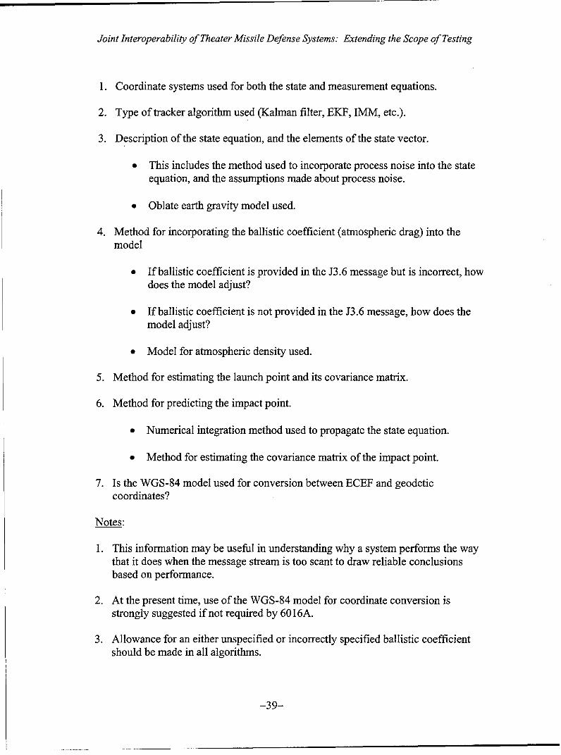
Joint Interoperability of Theater Missile Defense Systems: Extending the Scope of Testing
1. Coordinate systems used for both the state and measurement equations.
2. Type of tracker algorithm used (Kalman filter, EKF, 1MM, etc.).
3. Description of the state equation, and the elements of the state vector.
* This includes the method used to incorporate process noise into the stateequation, and the assumptions made about process noise.
* Oblate earth gravity model used.
4. Method for incorporating the ballistic coefficient (atmospheric drag) into themodel
"* If ballistic coefficient is provided in the J3.6 message but is incorrect, howdoes the model adjust?
"* If ballistic coefficient is not provided in the J3.6 message, how does themodel adjust?
"* Model for atmospheric density used.
5. Method for estimating the launch point and its covariance matrix.
6. Method for predicting the impact point.
"* Numerical integration method used to propagate the state equation.
"* Method for estimating the covariance matrix of the impact point.
7. Is the WGS-84 model used for conversion between ECEF and geodeticcoordinates?
Notes:
1. This information may be useful in understanding why a system performs the waythat it does when the message stream is too scant to draw reliable conclusionsbased on performance.
2. At the present time, use of the WGS-84 model for coordinate conversion isstrongly suggested if not required by 6016A.
3. Allowance for an either unspecified or incorrectly specified ballistic coefficientshould be made in all algorithms.
-39-
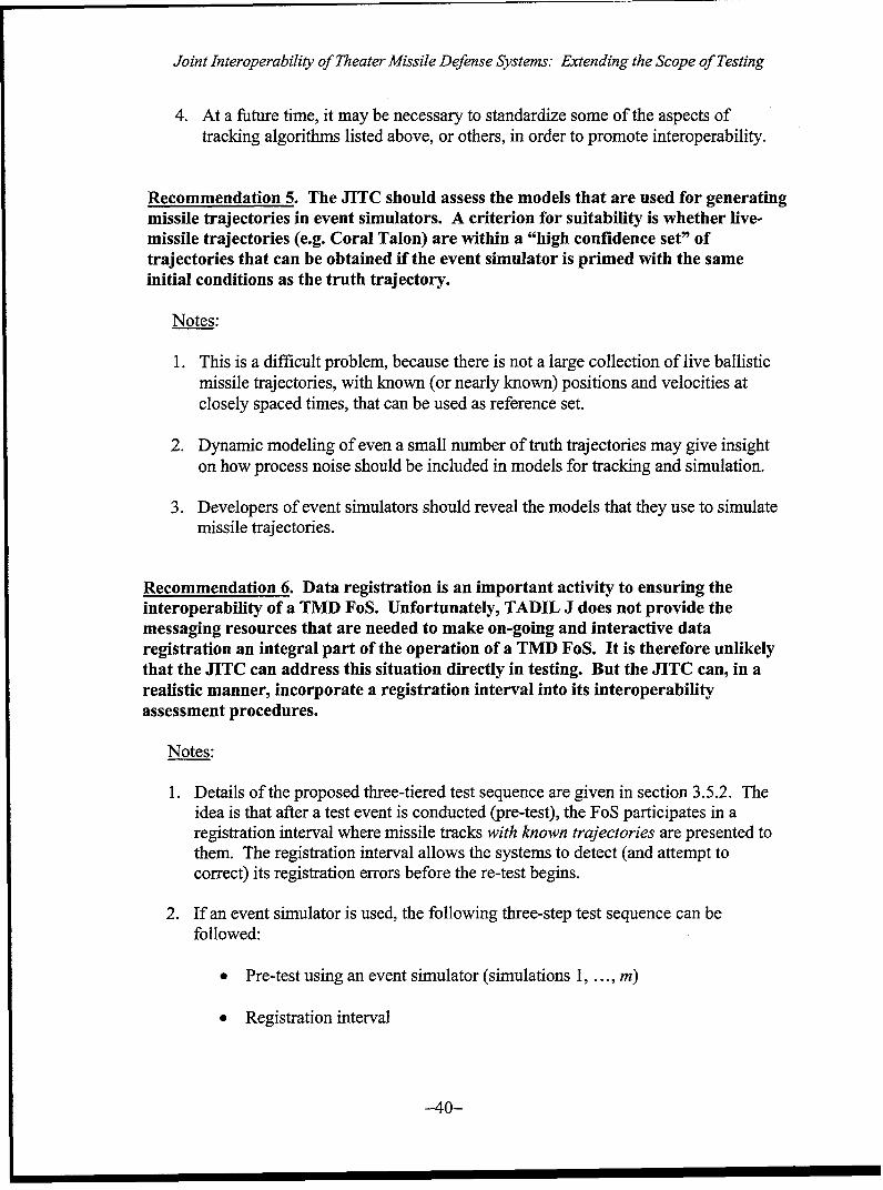
Joint Interoperability of Theater Missile Defense Systems: Extending the Scope of Testing
4. At a future time, it may be necessary to standardize some of the aspects oftracking algorithms listed above, or others, in order to promote interoperability.
Recommendation 5. The JITC should assess the models that are used for generatingmissile trajectories in event simulators. A criterion for suitability is whether live-missile trajectories (e.g. Coral Talon) are within a "high confidence set" oftrajectories that can be obtained if the event simulator is primed with the sameinitial conditions as the truth trajectory.
Notes:
1. This is a difficult problem, because there is not a large collection of live ballisticmissile trajectories, with known (or nearly known) positions and velocities atclosely spaced times, that can be used as reference set.
2. Dynamic modeling of even a small number of truth trajectories may give insighton how process noise should be included in models for tracking and simulation.
3. Developers of event simulators should reveal the models that they use to simulatemissile trajectories.
Recommendation 6. Data registration is an important activity to ensuring theinteroperability of a TMD FoS. Unfortunately, TADIL J does not provide themessaging resources that are needed to make on-going and interactive dataregistration an integral part of the operation of a TMD FoS. It is therefore unlikelythat the JITC can address this situation directly in testing. But the JITC can, in arealistic manner, incorporate a registration interval into its interoperabilityassessment procedures.
Notes:
1. Details of the proposed three-tiered test sequence are given in section 3.5.2. Theidea is that after a test event is conducted (pre-test), the FoS participates in aregistration interval where missile tracks with known trajectories are presented tothem. The registration interval allows the systems to detect (and attempt tocorrect) its registration errors before the re-test begins.
2. If an event simulator is used, the following three-step test sequence can befollowed:
"* Pre-test using an event simulator (simulations 1, ... , m)
"• Registration interval
-40-
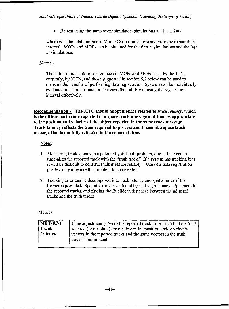
Joint Interoperability of Theater Missile Defense Systems: Extending the Scope of Testing
*Re-test using the same event simulator (simulations m+ 1, ... , 2m)
where m is the total number of Monte Carlo runs before and after the registrationinterval. MOPs and MOEs can be obtained for the first m simulations and the lastm simulations.
Metrics:
The "after minus before" differences in MONs and MOEs used by the JITCcurrently, by JCTN, and those suggested in section 5.2 below can be used tomeasure the benefits of perform-ing data registration. Systems can be individuallyevaluated in a similar manner, to assess their ability in using the registrationinterval effectively.
Recommendation 7. The JITC should adopt metrics related to track latency, whichis the difference in time reported in a space track message and time as appropriateto the position and velocity of the object reported in the same track message.Track latency reflects the time required to process and transmit a space trackmessage that is not fully reflected in the reported time.
Notes:
1 . Measuring track latency is a potentially difficult problem, due to the need totime-align the reported track with the "truth track." If a system has tracking biasit will be difficult to construct this measure reliably. Use of a data registrationpre-test may alleviate this problem to some extent.
2. Tracking error can be decomposed into track latency and spatial error if theformer is provided. Spatial error can be found by making a latency adjustment tothe reported tracks, and finding the Euclidean distances between the adjustedtracks and the truth tracks.
Metrics:
MET-R7-1 Time adjustment (+/-) to the reported track times such that the totalTrack squared (or absolute) error between the position and/or velocityLatency vectors in the reported tracks and the same vectors in the truth
tracks is minimized.
-41-
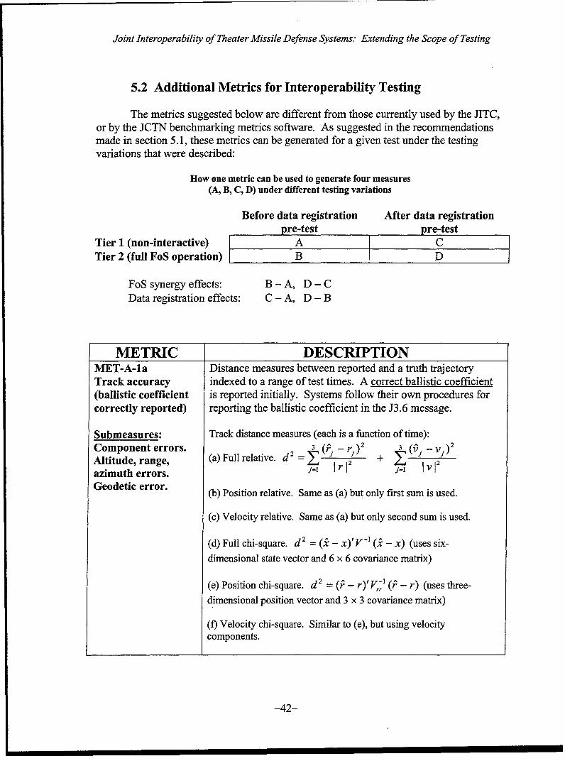
Joint Interoperability of Theater Missile Defense Systems: Extending the Scope of Testing
5.2 Additional Metrics for Interoperability Testing
The metrics suggested below are different from those currently used by the JITC,or by the JCTN benchmarking metrics software. As suggested in the recommendationsmade in section 5.1, these metrics can be generated for a given test under the testingvariations that were described:
How one metric can be used to generate four measures(A, B, C, D) under different testing variations
Before data registration After data registrationpre-test pre-test
Tier 1 (non-interactive) A CTier 2 (full FoS operation) B D
FoS synergy effects: B - A, D - CData registration effects: C - A, D - B
METRIC DESCRIPTIONMET-A-la Distance measures between reported and a truth trajectoryTrack accuracy indexed to a range of test times. A correct ballistic coefficient(ballistic coefficient is reported initially. Systems follow their own procedures forcorrectly reported) reporting the ballistic coefficient in the J3.6 message.
Submeasures: Track distance measures (each is a function of time):Component errors. 3 (j j)2 (vj)2Altitude, range, (a) Full relative. d2 =12 + --azimuth errors. j=I r j= v 2
Geodetic error. (b) Position relative. Same as (a) but only first sum is used.
(c) Velocity relative. Same as (a) but only second sum is used.
(d) Full chi-square. d 2 = (i - x)'V-' (.i - x) (uses six-
dimensional state vector and 6 x 6 covariance matrix)
(e) Position chi-square. d 2 = (P - r)'V4', (P - r) (uses three-
dimensional position vector and 3 x 3 covariance matrix)
(f) Velocity chi-square. Similar to (e), but using velocitycomponents.
-42-
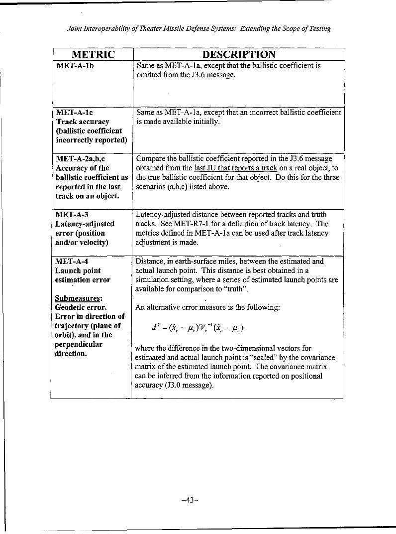
Joint Interoperability of Theater Missile Defense Systems: Extending the Scope of Testing
METRIC DESCRIPTIONMET-A-lb Same as MET-A-la, except that the ballistic coefficient is
omitted from the J3.6 message.
MET-A-ic Same as MET-A-la, except that an incorrect ballistic coefficientTrack accuracy is made available initially.(ballistic coefficientincorrectly reported)
MET-A-2a,b,c Compare the ballistic coefficient reported in the J3.6 messageAccuracy of the obtained from the last JU that reports a track on a real object, toballistic coefficient as the true ballistic coefficient for that object. Do this for the threereported in the last scenarios (a,b,c) listed above.track on an object.
NMET-A-3 Latency-adjusted distance between reported tracks and truthLatency-adjusted tracks. See MET-R7-1 for a definition of track latency. Theerror (position metrics defined in MET-A-l a can be used after track latencyand/or velocity) adjustment is made.
MET-A-4 Distance, in earth-surface miles, between the estimated andLaunch point actual launch point. This distance is best obtained in aestimation error simulation setting, where a series of estimated launch points are
available for comparison to "truth".Submeasures:Geodetic error. An alternative error measure is the following:Error in direction oftrajectory (plane of d 2 = (Qe - /ze)'V-I (Q~e - /e)
orbit), and in theperpendicular where the difference in the two-dimensional vectors fordirection. estimated and actual launch point is "scaled" by the covariance
matrix of the estimated launch point. The covariance matrixcan be inferred from the information reported on positionalaccuracy (J3.0 message).
-43-

Joint Interoperability of Theater Missile Defense Systems: Extending the Scope of Testing
METRIC DESCRIPTIONMET-A-5 Distance, in earth-surface miles, between the predicted and true
impact point. If an event simulator is used, the algorithm usedto generate the truth track can yield a mean impact point,/zp and
a covariance matrix XP for the impact point. An alternative
measure of the impact point prediction error is then given by
d' = (.i - PP, )(Y-P + VP)-1 (_i - PP)
where VP refers to the covariance matrix of the impact point
estimate (obtainable from the J3.0 message). If an eventsimulator is not used (i.e. a live missile trajectory), a dynamicmodel can be fit to the truth track and used to obtain thealternative measure. Both the distance and the alternativemeasure are best obtained in a simulation setting, where a seriesof predicted impact points are available for comparison to"truth"
MET-A-6 TBD. This is a subject of ongoing research. One possibleTQ Number approach is to view the TQ Number as a "null hypothesis" thataccuracy the covariance parameter defined by B (the look-up table
number) falls within a specified range. Data for conducting thehypothesis test consists of the difference between the estimatedand true track. In order to have adequate power for rejecting thenull hypothesis when it is false, sufficient data will benecessary.
-44-
Joint Interoperability of Theater Missile Defense Systems: Extending the Scope of Testing
BIBLIOGRAPHY
Baker, R.M.L. Jr., Astrodynamics: Applications and Advanced Topics, Academic Press,1967.
Barton, D.K., Modern Radar System Analysis, Artech House, 1988.
Bar-Shalom, Y., Multitarget-Multisensor Tracking.: Advanced Applications, ArtechHouse, 1990.
Bate, R.R., Mueller, D.D., and White, J.E., Fundamentals ofAstrodynamics, DoverPublications, 1971.
Beard, G.C., McCarter, T.G., and Spodeck, W., Real-time acquisition and trackingsystem with multiple Kalman filters, SPIE Proceedings: Acquisition, Tracking,and Pointing VIII (2221) 202-213, 1994.
Blackman, S.S., Multiple-Target Tracking with Radar Applications, Artech House, 1986.
Blackman, S. and Popoli, R., Design and Analysis of Modern Tracking Systems, ArtechHouse, 1999.
Breidt, F.J. and Carriquiry, A.L., Highest density gates for target tracking, IEEETransactions on Aerospace and Electronic Systems (36) 47-55, 2000.
Cardillo, G.P., Mrstik, A.V., and Plambeck, T., A track filter for reentry objects withuncertain drag, IEEE Transactions on Aerospace and Electronic Systems (35)394-409, 1999.
Chen, G., Wang, J., and Shieh, L.S., Interval Kalman filtering, IEEE Transactions onAerospace and Electronic Systems (33) 250-258, 1997.
Grewal, M.S. and Andrews, A.P., Kalman Filtering: Theory and Practice, Prentice Hall,1993.
Hemlick, R.E. and Rice, T.R., Removal of alignment errors in an integrated system oftwo 3-D sensors, IEEE Transactions on Aerospace and Electronic Systems (29)1333-1343, 1993.
Herrick, S., Astrodynamics: Orbit Correction, Perturbation Theory, Integration(Volume 2), Van Nostrand, 1972.
Heyler, G.A. and Murphy, P.K., Midcourse Space Experiment (MSX) closed-loop imageand track processing, SPIE Proceedings: Acquisition, Tracking, and PointingVIII (2221) 214-225, 1994.
-45-
Joint Interoperability of Theater Missile Defense Systems: Extending the Scope of Testing
Isaacson, J.A. and Vaughan, D.R., Estimation and Prediction of Ballistic MissileTrajectories, RAND Corporation, 1996.
Karniely, H. and Siegelmann, H.T., Sensor registration using neural networks, IEEETransactions on Aerospace and Electronic Systems (36) 85-101, 2000.
Leung, H., Hu, Z., and Blanchette, M., Evaluation of multiple radar target trackers instressful environments, IEEE Transactions on Aerospace and Electronic Systems(35) 663-674, 1999.
Leung, H. and Wu, J., Bayesian and Dempster-Shafer target identification for radarsurveillance, IEEE Transactions on Aerospace and Electronic Systems (36)432-447,2000.
Li, Y., Kirubarajan, T., Bar-Shalom, Y., and Yeddanapudi, M., Trajectory and launchpoint estimation for ballistic missiles from boost phase LOS measurements,Proceedings of the 1999 IEEE Aerospace Conference, 9903.
Merritt, P., Cusumano, S., Kramer, M., O'Keefe, S., and Higgs, C., Active tracking of aballistic missile in the boost phase, SPIE Proceedings: Acquisition, Tracking, andPointing X(2739) 19-29, 1996.
Merritt, P. and Kramer, M., Field test of active tracking of a ballistic missile in the boostphase, SPIE Proceedings: Acquisition, Tracking, and Pointing Xw (3086) 2-9,1997.
Reddy, S.P., Harvey, J.E., and Phillips, R.L., Pointing, tracking and acquisition throughatmospheric turbulence utilizing reciprocal path techniques, SPIE Proceedings:Acquisition, Tracking, and Pointing X (2739) 40-51, 1996.
San Jose, A., Theater ballistic missile defense-multisensor fusion, targeting and trackingtechniques, U.S. Naval Postgraduate School Masters thesis, 1998.
Saylor, D., Beard, G., Spodeck, W., and Fletcher, J., Portable ground-based infraredsensor for autonomous boost-phase target acquisition, tracking, and thrusttermination location, SPIE Proceedings: Acquisition, Tracking, and Pointing VIII(2221) 196-201, 1994
Siouris, G.M., Chen, G., and Wang, J., Tracking an incoming ballistic missile using anextended interval Kalman filter, IEEE Transactions on Aerospace and ElectronicSystems (33) 232-239, 1997.
Stevens, B.L. and Lewis, F.L., Aircraft Control and Simulation, Wiley, 1992.
Stone, L.D., Barlow, C.A., and Corwin, T.L., Bayesian Multiple Target Tracking, ArtechHouse, 1999.
-46-
Joint Interoperability of Theater Missile Defense Systems: Extending the Scope of Testing
Sullivan, R.G., A parametric study analyzing the impact of space-based sensors on NavyTheater Ballistic Defense performance for theater-wide sytems, SPIEProceedings: Acquisition, Tracking, and Pointing X (2739) 2-18, 1996.
Yeddanapudi, M., Bar-Shalom, Y., Pattipati, K.R., and Deb, S., Ballistic missiletrack initiation from satellite observations, IEEE Transactions on Aerospace andElectronic Systems (31) 1054-1070, 1995.
Zarchan, P., Tactical and Strategic Missile Guidance, Third Edition, American Instituteof Aeronautics and Astronautics, 1997.
Zhou, Y., Leung, H., and Blanchette, M., Sensor alignment with Earth-Centered Earth-fixed (ECEF) coordinate system. IEEE Transactions on Aerospace and ElectronicSystems (35) 410-418, 1999.
GOVERNMENT DOCUMENTS
DISA, Department of Defense Interface Standard, Tactical Digital Information Link(TADIL) A/B Message Standard (MIL-STD-601 IB), April 30, 1999.
DISA, Department of Defense Interface Standard, Tactical Digital Information Link(TADIL) J Message Standard (MIL-STD-6016A), April 30, 1999.
JITC, Detailed Event Plan (DEP) for the PATRIOT Advanced Capability Limited UserTest (LUT), Draft, February 2000.
JITC, Operational Issues for Joint TMD FoS Interoperability "Plug and Fight" (withcrosswalk), September 27, 1999.
JITC, PATRIOT Advanced Capability Level 3 (PAC-3) Interoperability CertificationEvaluation Plan, Living Document, June 1999.
ONR/BMDO, Joint Composite Tracking Network (JCTN) Benchmark EnvironmentUser's Guide, Iteration #1, Version 1.08, June 5, 2000.
Rothrock, R. and Drummond, 0., Pilot JCTN Algorithm Benchmarking PerformanceMetrics, 1999.
-47-
Joint Interoperability of Theater Missile Defense Systems: Extending the Scope of Testing
LIST OF ACRONYMS
601 lB MIL-STD-601 lB (TADIL A/B message standard)6016A MIL-STD-6016A (TADIL J message standard)
CEC Cooperative Engagement Capability (USN)ECEF Earth-centered, Earth-fixed (coordinate system)ECI Earth-centered inertial (coordinate system)EKF Extended Kalman filterFoS Family of systemsGPS Global Positioning SystemICBM Intercontinental ballistic missileIMM Interacting Multiple ModelIMU Inertial measurement unitIR InfraredJCTN Joint Composite Tracking NetworkJDN Joint Data NetworkJITC Joint Interoperability Test CommandJMOP Joint measure of performanceJU Joint userLOS Line of sight (sensor measurement type)LUT Limited user testMHT Multiple hypothesis trackingML Maximum likelihoodMMW Millimeter wave (radar)MOP Measure of performanceMTT Multiple target trackingNPG Network participation groupPAC-3 PATRIOT Advanced Capability Level 3PATRIOT Phased Array Tracking Radar to Intercept on TargetPDA Probabilistic data associationR' Reporting responsibilityRAE Range, azimuth, and elevation (coordinate system)RCS Radar cross-sectionSCC System coordinate centerTMD Theater missile defenseTN Track numberTQ Track qualityWGS-84 World Geodetic System (1984)
-48-
INITIAL DISTRIBUTION LIST
1. Research O ffice (Code 09) ........................................................................................ 1Naval Postgraduate SchoolMonterey, CA 93943-5000
2. Dudley Knox Library (Code 013) ............................................................................. 2Naval Postgraduate SchoolMonterey, CA 93943-5002
3. Defense Technical Information Center .................................................................... 28725 John J. Kingman Rd., STE 0944Ft. Belvoir, VA 22060-6218
4. E ditorial A ssistant ...................................................................................................... 1Dept of Operations ResearchNaval Postgraduate SchoolMonterey, CA 93943-5000
5. Prof. Robert A. Koyak (Code OR/Kr) ...................................................................... 4Dept of Operations ResearchNaval Postgraduate SchoolMonterey, CA 93943-5000
6. Prof. Donald P. Gaver (Code OR/Gv) ...................................................................... 1Dept of Operations ResearchNaval Postgraduate SchoolMonterey, CA 93943-5000
7. Leo H ansen ........................................................................................................... 4Joint Interoperability Test CommandBuilding 57305Fort Huachuca, AZ 85613-7020
-49-