monitoring the mechanical behaviour of electrically …pegorett/resources/107-pedrazzoli... ·...
TRANSCRIPT

Delivered by Ingenta toHebrew University of Jerusalem
IP 132645431Mon 22 Oct 2012 171546
RESEARCH
ARTIC
LE
Copyright copy 2012 American Scientific PublishersAll rights reservedPrinted in the United States of America
Journal ofNanoscience and Nanotechnology
Vol 12 4093ndash4102 2012
Monitoring the Mechanical Behaviour ofElectrically Conductive Polymer Nanocomposites
Under Ramp and Creep Conditions
D Pedrazzoli A Dorigatolowast and A PegorettiUniversity of Trento Department of Materials Engineering and Industrial Technologies and INSTM Research Unit
Via Mesiano 77 38123 Trento Italy
Various amounts of carbon black (CB) and carbon nanofibres (CNF) were dispersed in an epoxyresin to prepare nanocomposites whose mechanical behaviour under ramp and creep conditionswas monitored by electrical measurements The electrical resistivity of the epoxy resin was dramati-cally reduced by both nanofillers after the percolation threshold (1 wt for CB and 05 wt for CNF)reaching values in the range of 103ndash104 middot cm for filler loadings higher than 2 wt Due to thesynergistic effects between the nanofillers an epoxy system containing a total nanofiller amount of2 wt with a relative CBCNF ratio of 9010 was selected for the specific applications A direct cor-relation between the tensile strain and the increase of the electrical resistance was observed overthe whole experimental range and also the final failure of the samples was clearly detected Creeptests confirmed the possibility to monitor the various deformational stages under constant loadswith a strong dependency from the temperature and the applied stress The obtained results areencouraging for a possible application of nanomodified epoxy resin as a matrix for the preparationof structural composites with sensing (ie damage-monitoring) capabilities
Keywords Epoxy Nanocomposites Electrical Properties Mechanical Properties CreepMonitoring
1 INTRODUCTION
In the last 20 years there has been a strong emphasis onthe development of polymeric nanocomposites (PNCs)1
The rapid growth of experimental characterization tech-niques and theoretical prediction approaches promoted anextensive research in this field Nanostructured materi-als are characterized by a very high surface-to-volumeratio Therefore strong molecular interactions and uncon-ventional material properties may arise when nanofillersare dispersed in polymer matrices It has been widelyproven that the addition of a nanofiller to a polymericmatrix can increase its mechanical performances2ndash4 gasand solvents barrier properties56 degradation and chemi-cal resistances7 Moreover the above mentioned improve-ments can be obtained by adding relatively low amountof filler (generally less than 5 wt) avoiding the typi-cal drawbacks (embrittlement loss of transparency lossof lightness) associated to the usage of traditional organicmicrofillers8 In general the resulting properties depend onthe level of nanofiller dispersion within the matrix and onthe degree of filler-matrix interfacial interaction9
lowastAuthor to whom correspondence should be addressed
In the recent years a considerable interest arose towardcarbon based nanofillers due to their high thermal and elec-trical conductivities In fact various papers documentedhow the electrical conductivity of polymer matrices couldbe substantially improved through the introduction of con-ductive nanofillers such as metal nanopowders graphitenanoplatelets (GnP) carbon black (CB) and carbon nanofi-bres (CNF) The electrical behavior of these systems wassuccessfully described referring to the percolation theory10
After a given filler content the so-called percolationthreshold the conductive particles form a continuous net-work through the insulating matrix and the resistivitydrastically decreases by several orders of magnitude Thesimultaneous incorporation of two different nanofillerscould lead to synergistic effects in the conductivity behav-ior of the resulting materials11ndash16 For instance Li et alinvestigated the effects of hybrid carbon nanotubes (CNTs)and graphite nanoplatelets (GnPs) on the mechanical andelectrical properties of epoxy nanocomposites When thetotal filler loading was fixed at 2 wt the nanocompositecontaining 1 GnP and 1 CNT showed an electricalconductivity more than two orders of magnitude higherthan that of nanocomposites with 2 wt GnP alone14
J Nanosci Nanotechnol 2012 Vol 12 No 5 1533-48802012124093010 doi101166jnn20126219 4093
Delivered by Ingenta toHebrew University of Jerusalem
IP 132645431Mon 22 Oct 2012 171546
RESEARCH
ARTIC
LE
Monitoring the Mechanical Behaviour of Electrically Conductive PNCs Under Ramp and Creep Conditions Pedrazzoli et al
In a recent work17 we documented how the introductionof vapour grown carbon fibres (VGCF) and exfoliatedgraphite nanoplatelets (xGnP) in a poly(lactic acid) (PLA)matrix at a total filler content of 10 wt could promotea further decrease of surface resistivity with respect to theeffect played by the single nanofillersAs polymer matrix composites are particularly sensitive
to damages in the polymer matrix (such as matrix crack-ing) a reliable method for the detection and assessment ofsuch failures is highly desirable18 Furthermore an in-situmonitoring of the deformational behaviour and damagedevelopment could represent a useful tool to increase thereliability and lifetime as well as to ease the maintenanceof structural components exposed to static and cyclic load-ing conditions AC and DC electrical methods have beenextensively used to study a variety of damage mechanismsunder static and dynamic loading conditions19ndash28 If elec-trical conductivity methods have been widely investigatedfor the detection of failure in carbon fibre reinforced poly-mers (CFRPs) the application of an electrically conductivematrix allows one to extend the approach also to compos-ites reinforced with non conductive fibres (ie glass orpolymer fibres) Both nanoscaled23 and microscaled29 car-bon black particles have been used to modify the matrixof glass-fibre reinforced thermosets In these works it wasshown that external stress as well as apparent mechanicaldamage can be detected in these multiphase composites viaelectrical conductivity methods Recently Thostenson andChou reported on the usage of carbon nanotube modifiedglass fibre reinforced epoxy composites and their poten-tial for strain and damage sensing It could be shown thatwith a weight fraction of 05 CNTs in the epoxy matrixmechanical stressesstrains as well as matrix failure canbe detected via electrical conductivity measurements30
Despite its practical importance no papers can befound on the electrical monitoring of the mechanicalbehaviour of polymer composites under static (creep) load-ing conditions Therefore the analysis of the deformationalbehaviour of polymer matrices under constant loads couldrepresent and important issue for the health monitoring ofstructural compositesIn the present paper epoxy matrices modified with small
amounts (up to 4 wt) of conductive carbon nanofillers(CB and CNF) were prepared and thermo-mechanicallycharacterized After a preliminary optimization of the com-position combined mechanicalelectrical tests were per-formed in order to evaluate the sensing potential of thesemultiphase composites both under quasi-static and creepconditions
2 EXPERIMENTAL DETAILS
21 Materials and Sample Preparation
A bicomponent epoxy resin supplied by Elantas CamattiniSpA (Collecchio Italy) was used as matrix In particular
Table I Physical characteristics of epoxy resin cured at 24 h at roomtemperature followed by 15 h at 60 C according to the producer datasheet
Property Value
Density (gmiddotcmminus3 108ndash112Max Tg (C) 92ndash98Flexural modulus (GPa) 32ndash36Tensile strength (MPa) 67ndash75Ultimate elongation () 60ndash80
EC157 epoxy base (density = 115 g middot cmminus3 viscosity =700 mPa middot s) constituted by a mixture of BisphenolABisphenol FHexanediol diglycidyl ether (equivalentepoxide weight (EEW)= 165ndash180 g middotequivmiddotminus1 was mixedwith W152 LR amminic hardener (density= 095 g middotcmminus3viscosity = 30 mPa middot s) at a weight ratio of 10030 Themain physical properties of the cured material accord-ing to the producerrsquos datasheet are listed in Table ICarbon black nanoparticles (Ketjenblack EC600JD) wereprovided by Akzo Nobel Chemicals Spa (Arese Italy)This nanofiller is characterized by fine aggregates of spher-ical particles with typical dimension of around 30 nm anda density of 195 g middotcmminus3 Vapor grown carbon nanofibres(1195JN) have been supplied by NanoAmor Inc (Hous-ton TX USA) These fibres have a length of 5ndash40 ma core diameter of 05ndash10 nm and an outside diameter of240ndash500 nm Table II summarizes the experimental dataregarding density and specific surface area of the selectednanofillers All materials were used as receivedThe epoxy base the hardener and the nanofiller were
manually mixed for 5 minutes then mechanically stirredfor 5 min at 2000 rpm in a Dispermatreg F1 mixer andfinally degassed under vacuum for 10 min The compoundwas then poured in the cavities of silicone molds and ther-mally cured in an oven for 2 h at 50 C followed by 2 h at100 C This accelerated thermal treatment was preferredover that suggested by the resin supplier (24 h at roomtemperature followed by 15 h at 60 C) in order to speedup the preparation of the samples without affecting thefinal properties of the cured resin Samples were desig-nated with a code indicating the kind of matrix (Epoxy)the nanofiller type (CB or CNF) the weight ratio and totalamount For instance Epoxy-CB-2 indicates a nanocom-posite sample containing 2 wt of CB while Epoxy-CBCNF-9010-2 indicates the nanocomposite containing
Table II Density and specific surface area (SSA) of carbonaceousnanofillers used in this study
Nanofiller Densitya (g middot cmminus3) SSAb (m2 middotgminus1)
CB 195plusmn006 13531plusmn43CNF 178plusmn008 288plusmn02
aMeasured through a Micrometrics Accupycreg 1330 helium pycnometer bMeasuredthrough an ASAPreg 2010 Accelerated Surface Area and Porosimetry machine fol-lowing BET procedure
4094 J Nanosci Nanotechnol 12 4093ndash4102 2012
Delivered by Ingenta toHebrew University of Jerusalem
IP 132645431Mon 22 Oct 2012 171546
RESEARCH
ARTIC
LE
Pedrazzoli et al Monitoring the Mechanical Behaviour of Electrically Conductive PNCs Under Ramp and Creep Conditions
a CBCNF mixture (at a ratio of 9010) for a totalnanofiller content of 2 wt
22 Experimental Techniques
221 Thermo-Mechanical and MicrostructuralCharacterization
Rheological measurements on uncured resin were con-ducted both on pure epoxy and on nanofilled mixturesin a Brookfield RVT coaxial viscosimeter (MiddleboroMassachussetts USA) with an inner diameter of 17 mmand an outer diameter of 19 mm in a shear rate inter-val between 01 and 100 rad middot sminus1 For each compositiona sample volume of 8 ml was poured between the cylin-ders and tested at a temperature of 25 C controlled by athermostatic chamberMorphology of the cryofractured surfaces of fully cured
materials were investigated by a Zeiss Supra 40 fieldemission scanning electronic microscope (FESEM) at anacceleration voltage of about 1 kV and a pressure of10minus6 Torr The lateral surfaces of the samples were metal-ized with a silver paste before the observationsThermal properties of the samples were evaluated
through differential scanning calorimetry (DSC) tests per-formed with a Mettler DSC30 apparatus (SchwerzenbachSwitzerland) A thermal cycle from 0 C to 200 C ata heating rate of 10 C middotminminus1 under a nitrogen flow of100 ml middotminminus1 was adopted Quasi-static tensile tests wereperformed at 25 C on ISO 527 1BA dogbone samples(5 mm wide and 2 mm thick gage length of 30 mm) byusing an Instronreg 4502 tensile testing machine (NorwoodMassachusetts USA) at a constant crosshead speed of1 mm middotminminus1 For the evaluation of the elastic modulusthe strain was recorded through an Instron 2620-601 exten-someter (Norwood Massachusetts USA) with a gagelength of 125 mm According to ISO 527 standard theelastic modulus was determined as a secant value betweenstrain levels of 005 and 025 When the deformationreached a value higher than 025 the extensometer wasremoved and the deformation was monitored referring tothe crosshead displacement In this way both the elasticmodulus (E) and the quasi-static tensile properties at break(b b) were determined
222 Electrical Resistivity Measurements
Electrical bulk resistance measurements were performedat room temperature in direct-current mode A 6 12-digitelectrometerhigh resistance system supplied by KeithleyInstruments Inc (Cleveland Ohio USA) (model 6517A)was used Because of the high electrical resistance of thesamples and the relatively low contact resistance a 2-pointelectrical measurement was chosen as test configurationIn order to decrease the contact resistance the sample sur-faces in contact with the electrodes were painted with a sil-ver coating Measurements were carried out on rectangular
samples (cross section of 5 mmtimes3 mm length of 30 mm)and at least five specimens were tested for each sampleWhen the electrical resistance was lower than 105 mea-surements were carried out under an applied voltage of10 V and the resistance values were measured after a timelapse of 60 s in order to minimize time-dependent effectsWhen the electrical resistance was between 105 and 106 measurements were carried out under an applied voltageof 100 V When the electrical resistance was higher than106 measurements with an applied voltage of 1000 Vwere taken on square film samples (length of 95 mm andthickness of 3 mm) In this latter case coaxial electrodeswere used in order to minimize the amount of current flow-ing through the surface using text fixtures according toASTM 1D257 standard
223 Ramp and Creep Mechanical LoadingUnder Electrical Monitoring
Quasi-static ramp and creep tensile tests were performedat 25 C on ISO 527 1B dogbone specimens (10 mm wideand 4 mm thick) by using a MTS 858 Mini Bionix servo-hydraulic testing machine (Eden Prairie Minnesota USA)connected to a RT3 real-time digital control system by TrioSistemi e Misure Srl (Bergamo Italy) All test were per-formed inside an Instron model 3119 thermostatic chamber(Norwood Massachusetts USA) and strain was recordedthrough a MTS model n 63431F-24 extensometer (EdenPrairie Minnesota USA) with a gage length of 20 mmRamp tests were performed at a crosshead speed of
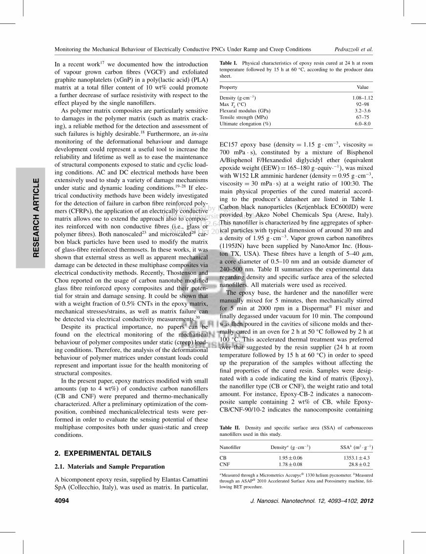
2 mm middotminminus1 Monitoring of electrical resistance and tem-perature was performed through a Keithley 6517A multi-meter A representative image of the experimental setup isreported in Figure 1(a) As depicted in Figure 1(b) a volt-age of 10 V was applied through two plastic clips coveredby thin copper plates within a distance of 30 mm Theelectrical contact zones were painted with a silver con-ductive coating The thermocouple of the multimeter wasplaced into the thermostatic chamber in proximity of thespecimen (Fig 1(b)) Both electrical resistance and tem-perature signals were acquired with a frequency of 10 HzCreep tests were performed at various stress levels (from
30 MPa to 50 MPa) in a temperature range between 20and 50 C for a loading time of 3600 s Both electricalresistance and temperature signals were acquired with afrequency of 1 Hz Tensile creep compliance Dt wascomputed by dividing the time dependent strain t bythe constant applied stress 0 Due to the large deforma-tion of the samples during the creep tests at high stressesor at elevated temperatures the deformation was moni-tored normalizing the crosshead displacement for the gagelength of the samples (80 mm) The electrical resistance ofundeformed specimens at various temperatures was mon-itored by using the same equipment In this way it was
J Nanosci Nanotechnol 12 4093ndash4102 2012 4095
Delivered by Ingenta toHebrew University of Jerusalem
IP 132645431Mon 22 Oct 2012 171546
RESEARCH
ARTIC
LE
Monitoring the Mechanical Behaviour of Electrically Conductive PNCs Under Ramp and Creep Conditions Pedrazzoli et al
(a)
(b)
Fig 1 (a) Setup for the monitoring of the electrical conductivity duringtensile mechanical tests under ramp and creep conditions (b) Particularof a clamped specimen
possible to correct electrical resistance data acquired dur-ing tensile and creep tests taking into account only theeffects associated to the mechanical deformationMoreover in order to evaluate the capability of the
tested samples to recover creep deformation strain recov-ery tests were also performed for a time of 9 h afterunloading
3 RESULTS AND DISCUSSION
31 Thermo-Mechanical Behavior andMicrostructural Features of Nanocomposites
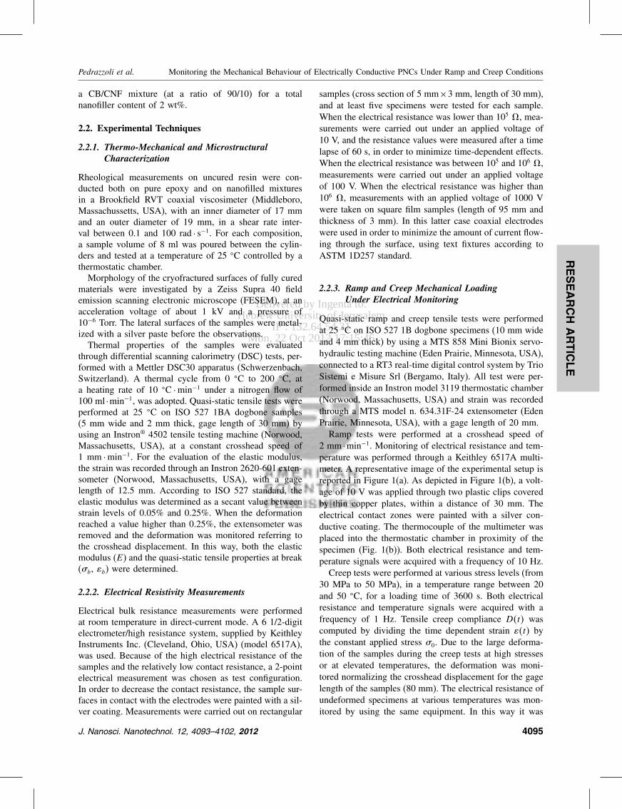
Shear viscosity values of neat epoxy and nanocompositesfilled with CB and CNF are plotted in Figures 2(a) and (b)
Fig 2 (a) Shear viscosity values of (bull) Epoxy () Epoxy-CB-05() Epoxy-CB-1 and () Epoxy-CB-2 nanocomposites (b) Shear vis-cosity values of (bull) Epoxy () Epoxy-CNF-05 and () Epoxy-CNF-1nanocomposites
respectively Some points are missing on the plots becausethe instrument was not able to measure the viscosity ofhighly viscous systems at elevated shear rates The staticviscosity of the neat resin is about 1700 mPa middot s whichis a value quite higher than that declared by the producer(150ndash250 mPa middot s at 25 C) We suppose that the adoptedhigh-rate mixing producer may have produced a heatingof the compound with some crosslinking As it commonlyhappens in nanofilled systems31 the viscosity of both CBand CNF composites increases with the filler content overthe whole range of shear rates It is interesting to note thatat a given nanofiller content CNF samples show higherviscosity values than the corresponding CB compoundsThis effect could be attributed to the different aspect ratioof the selected nanofillers in general a continuous networkcan be created by CNF at lower filler contents with respectto those required for particular fillers such as CB32
4096 J Nanosci Nanotechnol 12 4093ndash4102 2012
Delivered by Ingenta toHebrew University of Jerusalem
IP 132645431Mon 22 Oct 2012 171546
RESEARCH
ARTIC
LE
Pedrazzoli et al Monitoring the Mechanical Behaviour of Electrically Conductive PNCs Under Ramp and Creep Conditions
(a)
(b)
(c)
(d)
(e)
Fig 3 ESEM images of the fracture surfaces of (a) Epoxy (b) Epoxy-CB-05 (c) Epoxy-CB-3 (d) Epoxy-CNF-2 and (e) Epoxy-CBCNF-9010-2 nanocomposites
Information on the dependency of the morphology fromthe filler content and type have been collected by electronmicroscopy FESEM micrographs of neat resin Epoxy-CB-05 Epoxy-CB-3 Epoxy-CNF-2 and Epoxy-CBCNF-9010-2 samples are shown in Figures 3(a)ndash(e) As oftenreported in the scientific literature the fracture surfaceof neat epoxy appears quite smooth (Fig 3(a)) whilethe microstructure of CB nanomodified systems is char-acterized by the presence of primary particles arranged inaggregates and agglomerates homogeneously distributedwithin the polymer matrix Epoxy-CB-05 system is char-acterized by the presence of tiny and pale primary parti-cles with average diameter of about 30 nm organized inagglomerates of about 150 nm Epoxy-CB-3 system man-ifests a higher particle density and a higher tendency ofthe particles to form agglomerates In fact the agglom-erates are larger in size with respect to the systems atlower nanofiller content (about 250 nm) Epoxy-CNF-2system exhibits a rather complex microstructure Evenif some cavities due to fiber-matrix debonding phenom-ena are detectable on the fracture surface (Fig 3(d))it is very difficult to assess the presence of the nanofi-bres and to have information about their dispersion stateAlso in the Epoxy-CBCNF-9010-2 ternary composite itis rather difficult to detect the presence of nanofibres(Fig 3(e)) Table III summarizes the average dimension ofthe agglomerates of CB nanofilled systems As mentionedbefore the size of the agglomerates tends to increasewith the nanofiller content and Epoxy-CBCNF-9010-2presents an agglomerate size very similar to that of Epoxy-CB-2 composite As often reported for particulate fillednanocomposites33 as the filler amount increases the meaninterparticle distance diminishes and the probability ofaggregation is therefore enhancedTable IV summarize glass transition temperatures of
neat epoxy and relative nanocomposites collected duringthe first (Tg1) and second (Tg2) heating scans of DSC testsIn agreement with the producerrsquos data sheet neat resinshows Tg1 and Tg2 values of 82
C and 89 C respectivelyIf CB and CNF based nanocomposites are compared atthe same filler content no substantial differences can befound In fact Tg1 and Tg2 values increase for both mate-rials until a nanofiller concentration of 1 wt and thenit starts to decrease reaching a minimum for a nanofilleramount of 3 wt A similar trend has been previouslyobserved and reported by our group for various nanofilled
Table III Average dimension of the agglomerates detected on thetested samples
Sample Avg agglomerates size (nm)
Epoxy-CB-05 148plusmn12Epoxy-CB-1 144plusmn50Epoxy-CB-2 171plusmn28Epoxy-CB-3 252plusmn82Epoxy-CBCNF-9010-2 157plusmn29
J Nanosci Nanotechnol 12 4093ndash4102 2012 4097
Delivered by Ingenta toHebrew University of Jerusalem
IP 132645431Mon 22 Oct 2012 171546
RESEARCH
ARTIC
LE
Monitoring the Mechanical Behaviour of Electrically Conductive PNCs Under Ramp and Creep Conditions Pedrazzoli et al
Table IV Glass transition values of neat Epoxy and relative nanocom-posites from DSC tests Tg1 and Tg2 refer to the first and the secondheating cycle respectively
Sample Tg1 (C) Tg2 (C)
Epoxy 820 887
Epoxy-CB-05 825 894Epoxy-CB-1 842 905Epoxy-CB-2 813 883Epoxy-CB-3 802 882
Epoxy-CNF-05 825 892Epoxy-CNF-1 855 925Epoxy-CNF-2 822 890Epoxy-CNF-3 789 878
thermosets934ndash37 It could be hypothesized that for elevatedfiller amounts the crosslinking process is partially hinderedby the nanofiller In other words the observed Tg trendscould be explained considering the occurrence of two con-current phenomena as the filler content increases the chainblocking effect is likely to increase thus inducing a slightTg increase while at the same time polymer-filler chemi-cal interactions and the viscosity increase may reduce thecrosslinking degree of the matrix with a consequent reduc-tion of its TgRepresentative stressndashstrain curves of quasi-static ramp
tensile tests on neat epoxy and of CB filled nanocompos-ites are reported in Figure 4 while the most importantmechanical parameters are collected in Table V As oftenobserved with nanofilled systems3839 the elastic modu-lus of both CB and CNF nanocomposites progressivelyincreases with the filler content reaching a maximum fora nanofiller content of 3 wt In particular an increase of13 and 25 can be observed with respect to the neatepoxy resin for CNF and CB systems respectively Foras concern ultimate mechanical properties such as stressand strain at break values for both nanofillers a similar
Fig 4 Representative stressndashstrain curves of quasi-static tensile ramptests of neat epoxy and Epoxy-CB-x nanocomposites (x = 1ndash3 wt)
Table V Quasi-static tensile properties of neat Epoxy Epoxy-CB-x andEpoxy-CNF-x (x = 05 1 2 3 wt) nanocomposites
Sample E (GPa) b (MPa) b ()
Epoxy 303plusmn017 596plusmn08 53plusmn01
Epoxy-CB-05 296plusmn004 674plusmn17 57plusmn02Epoxy-CB-1 323plusmn011 697plusmn04 57plusmn01Epoxy-CB-2 361plusmn010 587plusmn05 42plusmn01Epoxy-CB-3 380plusmn015 550plusmn05 40plusmn01
Epoxy-CNF-05 285plusmn005 624plusmn04 49plusmn01Epoxy-CNF-1 310plusmn008 620plusmn23 56plusmn 02Epoxy-CNF-2 331plusmn005 502plusmn24 35plusmn01Epoxy-CNF-3 342plusmn010 447plusmn15 28plusmn01
trend can be observed with a maximum for a concen-tration of 1 wt The reduction of the tensile propertiesat break at elevated filler contents is more pronouncedwhen CNFs are utilized As previously reported by ourgroup233ndash3540 the progressive embrittlement of nanocom-posite systems at elevated filler amounts could be inducedby nanofiller aggregation If ternary systems with a totalnanofiller amount of 2 wt are considered (Table VI) itcan be concluded that both elastic modulus and ultimatetensile properties follow a rule of mixture
32 Electrical Resistivity of Nanocomposites
In Figure 5(a) the electrical resistivity of the neat epoxyand of nanocomposites is plotted as a function of thecontent of CB or CNF nanofillers The electrical resistiv-ity of the neat matrix is about 1016 middot cm in the typi-cal range generally reported for epoxy resins41 CB fillednanocomposites show a percolation threshold at a fillerconcentration between 1 and 2 wt with a resistivitydrop of more than eight orders of magnitude from 1 to 2wt reaching a plateau value at around 103 middot cm fornanofiller contents higher than 2 wt On the other handCNF based nanocomposites show a percolation thresholdlower than 05 wt For both fillers the electrical resis-tivity diminishes down to about 104 middot cm for a fillercontent of 4 wt As reported in literature1114 it is prob-able that the higher aspect ratio of CNF with respect toCB nanoparticles leads the formation of a conductive path
Table VI Quasi-static tensile properties of the nanocomposites con-taining both CB and CNF with a total nanofiller content of 2 wt
Sample E (GPa) b (MPa) b ()
Epoxy-CNF-2 331plusmn005 502plusmn24 35plusmn01Epoxy-CBCNF-2080-2 330plusmn010 516plusmn12 36plusmn01Epoxy-CBCNF-5050-2 338plusmn005 528plusmn13 37plusmn01Epoxy-CBCNF-6040-2 337plusmn008 546plusmn15 38plusmn01Epoxy-CBCNF-7030-2 340plusmn012 551plusmn11 39plusmn01Epoxy-CBCNF-8020-2 354plusmn010 578plusmn13 40plusmn01Epoxy-CBCNF-9010-2 358plusmn010 586plusmn15 41plusmn01Epoxy-CB-2 361plusmn010 587plusmn05 42plusmn01
4098 J Nanosci Nanotechnol 12 4093ndash4102 2012
Delivered by Ingenta toHebrew University of Jerusalem
IP 132645431Mon 22 Oct 2012 171546
RESEARCH
ARTIC
LE
Pedrazzoli et al Monitoring the Mechanical Behaviour of Electrically Conductive PNCs Under Ramp and Creep Conditions
Fig 5 (a) Electrical resistivity as a function of the nanofiller contentfor () Epoxy-CB-x nanocomposites (x = 1ndash5 wt) (bull) Epoxy-CNF-xnanocomposites (x = 1ndash4 wt) (b) Electrical resistivity as a functionof the CBCNF ratio for nanocomposites with () 05 wt () 1 wt(bull) 2 wt () 3 wt total amounts of nanofillers
at lower filler loadings but after the percolation thresh-old the contribution of the two nanofillers on the electri-cal conductivity of the composites is practically the sameAccording to the literature data matrices with an elec-trical resistivity as low as 104 middot cm seem suitable forelectrical monitoring1842ndash44 therefore both CB and CNFnanocomposites at filler concentrations higher than 2 wtcould be considered as good candidates for self-monitoringapplicationsIn Figure 5(b) the electrical resistivity of the nanocom-
posite systems containing both CB and CNF are plottedas a function of CB relative amount In most cases it canbe seen how electrical resistivity roughly follows the ruleof mixtures Interestingly a negative deviation from lin-earity can be detected for the systems with a total fillercontent of 2 wt Resistivity data follow a linear trenduntil a CB relative amount of 60ndash70 is reached and thena minimum is detected for a CBCNF ratio of 9010 Asreported by Sumfleth et al16 it can be hypothesized thatthe fine dispersion of CB and CNF leads to the forma-tion of co-supporting networks in which CB agglomerates
are interconnected by CNF dispersed in the interparticleregion Under these conditions the formation of a conduc-tive path within the matrix is favouredOn the basis of thermo-mechanical and electrical char-
acterization it emerges that 2 wt nanofilled systems dis-play good conductivity values with acceptable values oftensile strength and glass transition temperature There-fore Epoxy-CBCNF-9010-2 sample was chosen for thesubsequent characterization of the electrical monitoring oftensile mechanical behavior under ramp and creep loadingconditions
33 Monitoring the Mechanical ResponseUnder Ramp and Creep ConditionsThrough Electrical Resistivity
Ramp (ie constant strain rate) tensile tests were per-formed on Epoxy-CBCNF-9010-2 samples Stress-straincurve and the relative electrical resistance variation(RR0 during tensile test on the nanocomposite samplesare compared in Figure 6 It can be noticed that RR0
follows a linear trend for small deformations (ie lowerthan 05) and that for higher strain levels the slope ofthe curves slightly decreases When the final failure isapproached a sudden increase of RR0 values probablydue to a rapid damage evolution within the matrix canbe detected As reported by Nanni et al44 the separationbetween conductive particles at an increasing strain resultsin a higher electrical resistance Sensitivity is enhancedsince the conductive particles gradually separate understrain with a consequent enhancement of the electricalresistivity Moreover as the stress at break is approacheda permanent separation between particles occurs due tocracks nucleation with a sudden increase of the resis-tance values It can be therefore concluded that the selectednanocomposite system can be electrically monitored whena ramp load is applied
Fig 6 Stressndashstrain curve and relative resistance variation during ramptensile test on Epoxy-CBCNF-9010-2 sample
J Nanosci Nanotechnol 12 4093ndash4102 2012 4099
Delivered by Ingenta toHebrew University of Jerusalem
IP 132645431Mon 22 Oct 2012 171546
RESEARCH
ARTIC
LE
Monitoring the Mechanical Behaviour of Electrically Conductive PNCs Under Ramp and Creep Conditions Pedrazzoli et al
Room temperature creep compliance of neat matrix andEpoxy-CBCNF-9010-2 nanocomposite are compared atvarious stress levels in Figure 7(a) while creep compliancedata at 50 C are reported in Figure 7(b) for two differ-ent stress levels Both at room temperature and at 50 Cnanofilled sample manifests an interesting improvement ofthe creep stability with respect to the neat matrix In factboth elastic and viscoelastic components of the creep com-pliance are remarkably reduced by nanofiller introductionAs previously reported3845 the stabilizing effect providedby a nanofiller in a polymer matrix is more evident at ele-vated stress levels or at elevated test temperatures There-fore an appropriate combination of carbon nanofillers canbe exploited for preparing moderately conductive materi-als concurrently enhancing their creep stabilityIn Figure 8 creep compliance and electrical resistance
variation of Epoxy-CBCNF-9010-2 sample are reportedon the same plot for creep tests at various stresses per-formed at room temperature (Fig 8(a)) and at 50 C(Fig 8(b)) At room temperature a sudden increase of the
(a)
(b)
Fig 7 Comparison of the creep compliance of the neat matrix (- -) andof the Epoxy-CBCNF-9010-2 nanocomposite (mdash) at (a) room temper-ature and (b) at 50 C for different applied stresses
Fig 8 Creep compliance and resistance variation during creep loadingof Epoxy-CBCNF-9010-2 sample at various applied stresses at (a) roomtemperature and (b) at 50 C
electrical resistance upon load application can be observedproportionally to the stress level It is interesting to notehow RR0 tends to decrease with creep time for appliedstresses of 30 and 40 MPa while at 50 MPa an almostflat plot can be detected At 50 C creep compliance val-ues are noticeably higher than those registered at roomtemperature and a progressive increase of RR0 withtime can be observed regardless the stress level It can betherefore concluded that the creep monitoring capabilityof the selected nanocomposites is strongly affected by theapplied stress and the temperature Different deformationand conduction mechanisms could be tentatively invokedto explain the trend of the electrical resistivity undercreep conditions It is well known that both microstructureand electrical conduction behaviour of polymeric materialsis strongly influenced by time dependent mechanisms46
It can be hypothesized that as a consequence of theinstantaneous application of the creep load the conduc-tive network within the polymer matrix is destroyed anda resistivity increase is observed When the kinetics ofdeformational processes is low (ie at low temperatures
4100 J Nanosci Nanotechnol 12 4093ndash4102 2012
Delivered by Ingenta toHebrew University of Jerusalem
IP 132645431Mon 22 Oct 2012 171546
RESEARCH
ARTIC
LE
Pedrazzoli et al Monitoring the Mechanical Behaviour of Electrically Conductive PNCs Under Ramp and Creep Conditions
andor at low stresses) nanoparticles are able to re-form aconductive network thus inducing a progressive decreaseof the electrical resistance On the other hand at elevatedcreep stresses andor temperatures the higher kinetics ofthe deformational processes may hinder interparticle inter-actions and the subsequent re-formation of the conductivepath with a progressive increase of RR0 values withtime In any case further investigations are needed to gaina better comprehension of the observed phenomenonIn order to investigate the potential of the selected
nanocomposite system for monitoring the strain recov-ery processes after creep loading some tests were per-formed In Figure 9(a) the plots of the deformation of theEpoxy-CBCNF-9010-2 sample during creep and recov-ery tests performed both at room temperature and at50 C are reported while in Figure 9(b) the correspon-dent relative resistance values are represented When the
(a)
(b)
Fig 9 (a) Relative deformation and (b) relative values of the electricalresistance of the Epoxy-CBCNF-9010-2 sample for a creep test andfollowing recovery performed at room temperature and at 50 C (appliedstress of 20 MPa)
creep test is performed at room temperature the sampleis able to recover practically all the applied deformationafter unloading while a remarkable residual deformationremains at the end of the recovery stage if the test is car-ried out at 50 C It is interesting to note how the electricalresistance measured at the end of the recovery at 20 Cis similar to the RR0 value registered before the appli-cation of the load On the other hand at 50 C the finalresistance is considerably higher than that determined atthe beginning of the creep stage This permanent increaseof the electrical resistance registered at elevated tempera-ture is clearly related to the permanent deformation andordamage evolution within the epoxy matrix accumulatedduring the loading stage
4 CONCLUSIONS
Electrically conductive nanocomposites were prepared byadding various amounts of carbon black and carbon nanofi-bres in an epoxy matrix The mechanical characterizationof the resulting composites highlighted how both CB andCNF were able to improve the elastic modulus of the neatmatrix with a positive effect on its ultimate properties upto a filler content of 1 wt The introduction of both thenanofillers lead to a dramatic decrease of the electricalresistivity down to values of 103ndash104 middotcm for filler load-ings higher than 2 wt Moreover a positive synergisticeffect was detected for epoxy systems containing a totalnanofiller amount of 2 wt with a relative CBCNF ratioof 9010The monitoring of tensile tests under ramp conditions
highlighted a direct correlation between the tensile strainand the increase of the electrical resistance over the wholeduration of the tests Monitoring of tensile creep testsevidenced a complex electrical response depending onthe temperature and applied stress levels Moreover theepoxy nanocomposite under investigation allowed also anelectrical monitoring of the strain recovery process afterunloading These results are encouraging for a possibleapplication of the nanomodified epoxy for the prepara-tion of fibre reinforced structural composites with damage-sensing capabilities
References and Notes
1 J H Koo Polymer Nanocomposite Process Characterization andApplications McGraw-Hill New York (2006)
2 F Bondioli A Dorigato P Fabbri M Messori and A PegorettiPolym Eng Sci 48 448 (2008)
3 O Starkova J L Yang and Z Zhang Compos Sci Technol67 2691 (2007)
4 Z Zhang J L Yang and K Friedrich Polymer 45 3481 (2004)5 W J Choi S H Kim Y J Kim and S C Kim Polymer 45 6045
(2004)6 M Gorrasi M Tortora and G Vittoria J Polym Sci Part B
Polym Phys 43 2454 (2005)
J Nanosci Nanotechnol 12 4093ndash4102 2012 4101
Delivered by Ingenta toHebrew University of Jerusalem
IP 132645431Mon 22 Oct 2012 171546
RESEARCH
ARTIC
LE
Monitoring the Mechanical Behaviour of Electrically Conductive PNCs Under Ramp and Creep Conditions Pedrazzoli et al
7 C Zhao H Qin F Gong M Feng S Zhang and M Yang PolymDegrad Stab 87 183 (2005)
8 C F Ou and M C Hsu J Polym Res 14 373 (2007)9 A Pegoretti A Dorigato and A Penati Eur Polym J 44 1662
(2008)10 M Traina A Pegoretti and A Penati J Appl Polym Sci 106 2065
(2007)11 Z J Fan C Zheng T Wei Y C Zhang and G L Luo Polym
Eng Sci 49 2041 (2009)12 S Kumar L L Sun S Caceres B Li W Wood A Perugini R G
Maguire and W H Zhong Nanotechnology 21 105702 (2010)13 J H Lee Y K Jang C E Hong N H Kim P Li and H K Lee
J Power Sources 193 523 (2009)14 J Li P S Wong and J K Kim Materials Science and Engineer-
ing a-Structural Materials Properties Microstructure and Processing483ndash84 660 (2008)
15 P C Ma M Y Liu H Zhang S Q Wang R Wang K WangY K Wong B Z Tang S H Hong K W Paik and J K KimAcs Applied Materials amp Interfaces 1 1090 (2009)
16 J Sumfleth X C Adroher and K Schulte J Mater Sci 44 3241(2009)
17 M Tait A Pegoretti A Dorigato and K Kalaitzidou Carbon49 4280 (2011)
18 L Boumleger M H G Wichmann L O Meyer and K SchulteCompos Sci Technol 68 1886 (2008)
19 J C Abry S Bochard A Chateauminois M Salvia and G GiraudCompos Sci Technol 59 925 (1999)
20 J C Abry Y K Choi A Chateauminois B Dalloz G Giraud andM Salvia Compos Sci Technol 61 855 (2001)
21 P E Irving and C Thiagarajan Smart Materials amp Structures 7 456(1998)
22 A S Kaddour F A R Alsalehi S T S Alhassani and M JHinton Compos Sci Technol 51 377 (1994)
23 M Kupke K Schulte and R Schuler Compos Sci Technol 61 837(2001)
24 D C Seo and J J Lee Compos Struct 47 525 (1999)25 A Todoroki H Kobayashi and K Matuura Jsme International
Journal Series a-Mechanics and Material Engineering 38 524(1995)
26 A Todoroki K Omagari Y Shimamura and H KobayashiCompos Sci Technol 66 1539 (2006)
27 A Todoroki M Tanaka Y Shimamura and H KobayashiAdv Compos Mater 13 107 (2004)
28 A Todoroki and Y Tanaka Compos Sci Technol 62 629(2002)
29 N Muto Y Arai S G Shin H Matsubara H Yanagida M Sugitaand T Nakatsuji Compos Sci Technol 61 875 (2001)
30 E T Thostenson and T W Chou Advanced Materials 18 2837(2006)
31 A Dorigato S Morandi and A Pegoretti J Compos Mater(in press)
32 J Sumfleth S T Buschhorn and K Schulte J Mater Sci 46 659(2010)
33 A Dorigato M DrsquoAmato and A Pegoretti J Polym Res (in press)34 A Dorigato A Pegoretti F Bondioli and M Messori Composite
Interfaces 17 873 (2010)35 A Dorigato and A Pegoretti J Nanopart Res 13 2429 (2011)36 A Dorigato A Pegoretti and A Penati J Reinf Plast Compos
30 325 (2011)37 A Dorigato A Pegoretti and M Quaresimin Mater Sci Eng A
528 6324 (2011)38 A Dorigato and A Pegoretti Polym Int 59 719 (2010)39 A Dorigato L Fambri A Pegoretti M Slouf and J Kolarik
J Appl Polym Sci 119 3393 (2011)40 F Bondioli A Dorigato P Fabbri M Messori and A Pegoretti
J Appl Polym Sci 112 1045 (2009)41 Y Choi K Sugimoto S Song Y Gotoh Y Ohkoshi and M Endo
Carbon 43 2199 (2005)42 V Kostopoulos A Vavouliotis P Karapappas P Tsotra and
A Paipetis J Intell Mater Syst Struct 20 1025 (2009)43 C D Liu L F Cheng X G Luan B Li and J Zhou Mater Lett
62 3922 (2008)44 F Nanni G Ruscito D Puglia A Terenzi J M Kenny and
G Gusmano Compos Sci Technol 71 1 (2011)45 A Dorigato A Pegoretti and J Kolarik Polym Compos 31 1947
(2010)46 C Zhang P Wang C Ma G Wu and M Sumita Polymer 47 466
(2006)
Received 27 September 2011 Accepted 9 November 2011
4102 J Nanosci Nanotechnol 12 4093ndash4102 2012
Delivered by Ingenta toHebrew University of Jerusalem
IP 132645431Mon 22 Oct 2012 171546
RESEARCH
ARTIC
LE
Monitoring the Mechanical Behaviour of Electrically Conductive PNCs Under Ramp and Creep Conditions Pedrazzoli et al
In a recent work17 we documented how the introductionof vapour grown carbon fibres (VGCF) and exfoliatedgraphite nanoplatelets (xGnP) in a poly(lactic acid) (PLA)matrix at a total filler content of 10 wt could promotea further decrease of surface resistivity with respect to theeffect played by the single nanofillersAs polymer matrix composites are particularly sensitive
to damages in the polymer matrix (such as matrix crack-ing) a reliable method for the detection and assessment ofsuch failures is highly desirable18 Furthermore an in-situmonitoring of the deformational behaviour and damagedevelopment could represent a useful tool to increase thereliability and lifetime as well as to ease the maintenanceof structural components exposed to static and cyclic load-ing conditions AC and DC electrical methods have beenextensively used to study a variety of damage mechanismsunder static and dynamic loading conditions19ndash28 If elec-trical conductivity methods have been widely investigatedfor the detection of failure in carbon fibre reinforced poly-mers (CFRPs) the application of an electrically conductivematrix allows one to extend the approach also to compos-ites reinforced with non conductive fibres (ie glass orpolymer fibres) Both nanoscaled23 and microscaled29 car-bon black particles have been used to modify the matrixof glass-fibre reinforced thermosets In these works it wasshown that external stress as well as apparent mechanicaldamage can be detected in these multiphase composites viaelectrical conductivity methods Recently Thostenson andChou reported on the usage of carbon nanotube modifiedglass fibre reinforced epoxy composites and their poten-tial for strain and damage sensing It could be shown thatwith a weight fraction of 05 CNTs in the epoxy matrixmechanical stressesstrains as well as matrix failure canbe detected via electrical conductivity measurements30
Despite its practical importance no papers can befound on the electrical monitoring of the mechanicalbehaviour of polymer composites under static (creep) load-ing conditions Therefore the analysis of the deformationalbehaviour of polymer matrices under constant loads couldrepresent and important issue for the health monitoring ofstructural compositesIn the present paper epoxy matrices modified with small
amounts (up to 4 wt) of conductive carbon nanofillers(CB and CNF) were prepared and thermo-mechanicallycharacterized After a preliminary optimization of the com-position combined mechanicalelectrical tests were per-formed in order to evaluate the sensing potential of thesemultiphase composites both under quasi-static and creepconditions
2 EXPERIMENTAL DETAILS
21 Materials and Sample Preparation
A bicomponent epoxy resin supplied by Elantas CamattiniSpA (Collecchio Italy) was used as matrix In particular
Table I Physical characteristics of epoxy resin cured at 24 h at roomtemperature followed by 15 h at 60 C according to the producer datasheet
Property Value
Density (gmiddotcmminus3 108ndash112Max Tg (C) 92ndash98Flexural modulus (GPa) 32ndash36Tensile strength (MPa) 67ndash75Ultimate elongation () 60ndash80
EC157 epoxy base (density = 115 g middot cmminus3 viscosity =700 mPa middot s) constituted by a mixture of BisphenolABisphenol FHexanediol diglycidyl ether (equivalentepoxide weight (EEW)= 165ndash180 g middotequivmiddotminus1 was mixedwith W152 LR amminic hardener (density= 095 g middotcmminus3viscosity = 30 mPa middot s) at a weight ratio of 10030 Themain physical properties of the cured material accord-ing to the producerrsquos datasheet are listed in Table ICarbon black nanoparticles (Ketjenblack EC600JD) wereprovided by Akzo Nobel Chemicals Spa (Arese Italy)This nanofiller is characterized by fine aggregates of spher-ical particles with typical dimension of around 30 nm anda density of 195 g middotcmminus3 Vapor grown carbon nanofibres(1195JN) have been supplied by NanoAmor Inc (Hous-ton TX USA) These fibres have a length of 5ndash40 ma core diameter of 05ndash10 nm and an outside diameter of240ndash500 nm Table II summarizes the experimental dataregarding density and specific surface area of the selectednanofillers All materials were used as receivedThe epoxy base the hardener and the nanofiller were
manually mixed for 5 minutes then mechanically stirredfor 5 min at 2000 rpm in a Dispermatreg F1 mixer andfinally degassed under vacuum for 10 min The compoundwas then poured in the cavities of silicone molds and ther-mally cured in an oven for 2 h at 50 C followed by 2 h at100 C This accelerated thermal treatment was preferredover that suggested by the resin supplier (24 h at roomtemperature followed by 15 h at 60 C) in order to speedup the preparation of the samples without affecting thefinal properties of the cured resin Samples were desig-nated with a code indicating the kind of matrix (Epoxy)the nanofiller type (CB or CNF) the weight ratio and totalamount For instance Epoxy-CB-2 indicates a nanocom-posite sample containing 2 wt of CB while Epoxy-CBCNF-9010-2 indicates the nanocomposite containing
Table II Density and specific surface area (SSA) of carbonaceousnanofillers used in this study
Nanofiller Densitya (g middot cmminus3) SSAb (m2 middotgminus1)
CB 195plusmn006 13531plusmn43CNF 178plusmn008 288plusmn02
aMeasured through a Micrometrics Accupycreg 1330 helium pycnometer bMeasuredthrough an ASAPreg 2010 Accelerated Surface Area and Porosimetry machine fol-lowing BET procedure
4094 J Nanosci Nanotechnol 12 4093ndash4102 2012
Delivered by Ingenta toHebrew University of Jerusalem
IP 132645431Mon 22 Oct 2012 171546
RESEARCH
ARTIC
LE
Pedrazzoli et al Monitoring the Mechanical Behaviour of Electrically Conductive PNCs Under Ramp and Creep Conditions
a CBCNF mixture (at a ratio of 9010) for a totalnanofiller content of 2 wt
22 Experimental Techniques
221 Thermo-Mechanical and MicrostructuralCharacterization
Rheological measurements on uncured resin were con-ducted both on pure epoxy and on nanofilled mixturesin a Brookfield RVT coaxial viscosimeter (MiddleboroMassachussetts USA) with an inner diameter of 17 mmand an outer diameter of 19 mm in a shear rate inter-val between 01 and 100 rad middot sminus1 For each compositiona sample volume of 8 ml was poured between the cylin-ders and tested at a temperature of 25 C controlled by athermostatic chamberMorphology of the cryofractured surfaces of fully cured
materials were investigated by a Zeiss Supra 40 fieldemission scanning electronic microscope (FESEM) at anacceleration voltage of about 1 kV and a pressure of10minus6 Torr The lateral surfaces of the samples were metal-ized with a silver paste before the observationsThermal properties of the samples were evaluated
through differential scanning calorimetry (DSC) tests per-formed with a Mettler DSC30 apparatus (SchwerzenbachSwitzerland) A thermal cycle from 0 C to 200 C ata heating rate of 10 C middotminminus1 under a nitrogen flow of100 ml middotminminus1 was adopted Quasi-static tensile tests wereperformed at 25 C on ISO 527 1BA dogbone samples(5 mm wide and 2 mm thick gage length of 30 mm) byusing an Instronreg 4502 tensile testing machine (NorwoodMassachusetts USA) at a constant crosshead speed of1 mm middotminminus1 For the evaluation of the elastic modulusthe strain was recorded through an Instron 2620-601 exten-someter (Norwood Massachusetts USA) with a gagelength of 125 mm According to ISO 527 standard theelastic modulus was determined as a secant value betweenstrain levels of 005 and 025 When the deformationreached a value higher than 025 the extensometer wasremoved and the deformation was monitored referring tothe crosshead displacement In this way both the elasticmodulus (E) and the quasi-static tensile properties at break(b b) were determined
222 Electrical Resistivity Measurements
Electrical bulk resistance measurements were performedat room temperature in direct-current mode A 6 12-digitelectrometerhigh resistance system supplied by KeithleyInstruments Inc (Cleveland Ohio USA) (model 6517A)was used Because of the high electrical resistance of thesamples and the relatively low contact resistance a 2-pointelectrical measurement was chosen as test configurationIn order to decrease the contact resistance the sample sur-faces in contact with the electrodes were painted with a sil-ver coating Measurements were carried out on rectangular
samples (cross section of 5 mmtimes3 mm length of 30 mm)and at least five specimens were tested for each sampleWhen the electrical resistance was lower than 105 mea-surements were carried out under an applied voltage of10 V and the resistance values were measured after a timelapse of 60 s in order to minimize time-dependent effectsWhen the electrical resistance was between 105 and 106 measurements were carried out under an applied voltageof 100 V When the electrical resistance was higher than106 measurements with an applied voltage of 1000 Vwere taken on square film samples (length of 95 mm andthickness of 3 mm) In this latter case coaxial electrodeswere used in order to minimize the amount of current flow-ing through the surface using text fixtures according toASTM 1D257 standard
223 Ramp and Creep Mechanical LoadingUnder Electrical Monitoring
Quasi-static ramp and creep tensile tests were performedat 25 C on ISO 527 1B dogbone specimens (10 mm wideand 4 mm thick) by using a MTS 858 Mini Bionix servo-hydraulic testing machine (Eden Prairie Minnesota USA)connected to a RT3 real-time digital control system by TrioSistemi e Misure Srl (Bergamo Italy) All test were per-formed inside an Instron model 3119 thermostatic chamber(Norwood Massachusetts USA) and strain was recordedthrough a MTS model n 63431F-24 extensometer (EdenPrairie Minnesota USA) with a gage length of 20 mmRamp tests were performed at a crosshead speed of
2 mm middotminminus1 Monitoring of electrical resistance and tem-perature was performed through a Keithley 6517A multi-meter A representative image of the experimental setup isreported in Figure 1(a) As depicted in Figure 1(b) a volt-age of 10 V was applied through two plastic clips coveredby thin copper plates within a distance of 30 mm Theelectrical contact zones were painted with a silver con-ductive coating The thermocouple of the multimeter wasplaced into the thermostatic chamber in proximity of thespecimen (Fig 1(b)) Both electrical resistance and tem-perature signals were acquired with a frequency of 10 HzCreep tests were performed at various stress levels (from
30 MPa to 50 MPa) in a temperature range between 20and 50 C for a loading time of 3600 s Both electricalresistance and temperature signals were acquired with afrequency of 1 Hz Tensile creep compliance Dt wascomputed by dividing the time dependent strain t bythe constant applied stress 0 Due to the large deforma-tion of the samples during the creep tests at high stressesor at elevated temperatures the deformation was moni-tored normalizing the crosshead displacement for the gagelength of the samples (80 mm) The electrical resistance ofundeformed specimens at various temperatures was mon-itored by using the same equipment In this way it was
J Nanosci Nanotechnol 12 4093ndash4102 2012 4095
Delivered by Ingenta toHebrew University of Jerusalem
IP 132645431Mon 22 Oct 2012 171546
RESEARCH
ARTIC
LE
Monitoring the Mechanical Behaviour of Electrically Conductive PNCs Under Ramp and Creep Conditions Pedrazzoli et al
(a)
(b)
Fig 1 (a) Setup for the monitoring of the electrical conductivity duringtensile mechanical tests under ramp and creep conditions (b) Particularof a clamped specimen
possible to correct electrical resistance data acquired dur-ing tensile and creep tests taking into account only theeffects associated to the mechanical deformationMoreover in order to evaluate the capability of the
tested samples to recover creep deformation strain recov-ery tests were also performed for a time of 9 h afterunloading
3 RESULTS AND DISCUSSION
31 Thermo-Mechanical Behavior andMicrostructural Features of Nanocomposites
Shear viscosity values of neat epoxy and nanocompositesfilled with CB and CNF are plotted in Figures 2(a) and (b)
Fig 2 (a) Shear viscosity values of (bull) Epoxy () Epoxy-CB-05() Epoxy-CB-1 and () Epoxy-CB-2 nanocomposites (b) Shear vis-cosity values of (bull) Epoxy () Epoxy-CNF-05 and () Epoxy-CNF-1nanocomposites
respectively Some points are missing on the plots becausethe instrument was not able to measure the viscosity ofhighly viscous systems at elevated shear rates The staticviscosity of the neat resin is about 1700 mPa middot s whichis a value quite higher than that declared by the producer(150ndash250 mPa middot s at 25 C) We suppose that the adoptedhigh-rate mixing producer may have produced a heatingof the compound with some crosslinking As it commonlyhappens in nanofilled systems31 the viscosity of both CBand CNF composites increases with the filler content overthe whole range of shear rates It is interesting to note thatat a given nanofiller content CNF samples show higherviscosity values than the corresponding CB compoundsThis effect could be attributed to the different aspect ratioof the selected nanofillers in general a continuous networkcan be created by CNF at lower filler contents with respectto those required for particular fillers such as CB32
4096 J Nanosci Nanotechnol 12 4093ndash4102 2012
Delivered by Ingenta toHebrew University of Jerusalem
IP 132645431Mon 22 Oct 2012 171546
RESEARCH
ARTIC
LE
Pedrazzoli et al Monitoring the Mechanical Behaviour of Electrically Conductive PNCs Under Ramp and Creep Conditions
(a)
(b)
(c)
(d)
(e)
Fig 3 ESEM images of the fracture surfaces of (a) Epoxy (b) Epoxy-CB-05 (c) Epoxy-CB-3 (d) Epoxy-CNF-2 and (e) Epoxy-CBCNF-9010-2 nanocomposites
Information on the dependency of the morphology fromthe filler content and type have been collected by electronmicroscopy FESEM micrographs of neat resin Epoxy-CB-05 Epoxy-CB-3 Epoxy-CNF-2 and Epoxy-CBCNF-9010-2 samples are shown in Figures 3(a)ndash(e) As oftenreported in the scientific literature the fracture surfaceof neat epoxy appears quite smooth (Fig 3(a)) whilethe microstructure of CB nanomodified systems is char-acterized by the presence of primary particles arranged inaggregates and agglomerates homogeneously distributedwithin the polymer matrix Epoxy-CB-05 system is char-acterized by the presence of tiny and pale primary parti-cles with average diameter of about 30 nm organized inagglomerates of about 150 nm Epoxy-CB-3 system man-ifests a higher particle density and a higher tendency ofthe particles to form agglomerates In fact the agglom-erates are larger in size with respect to the systems atlower nanofiller content (about 250 nm) Epoxy-CNF-2system exhibits a rather complex microstructure Evenif some cavities due to fiber-matrix debonding phenom-ena are detectable on the fracture surface (Fig 3(d))it is very difficult to assess the presence of the nanofi-bres and to have information about their dispersion stateAlso in the Epoxy-CBCNF-9010-2 ternary composite itis rather difficult to detect the presence of nanofibres(Fig 3(e)) Table III summarizes the average dimension ofthe agglomerates of CB nanofilled systems As mentionedbefore the size of the agglomerates tends to increasewith the nanofiller content and Epoxy-CBCNF-9010-2presents an agglomerate size very similar to that of Epoxy-CB-2 composite As often reported for particulate fillednanocomposites33 as the filler amount increases the meaninterparticle distance diminishes and the probability ofaggregation is therefore enhancedTable IV summarize glass transition temperatures of
neat epoxy and relative nanocomposites collected duringthe first (Tg1) and second (Tg2) heating scans of DSC testsIn agreement with the producerrsquos data sheet neat resinshows Tg1 and Tg2 values of 82
C and 89 C respectivelyIf CB and CNF based nanocomposites are compared atthe same filler content no substantial differences can befound In fact Tg1 and Tg2 values increase for both mate-rials until a nanofiller concentration of 1 wt and thenit starts to decrease reaching a minimum for a nanofilleramount of 3 wt A similar trend has been previouslyobserved and reported by our group for various nanofilled
Table III Average dimension of the agglomerates detected on thetested samples
Sample Avg agglomerates size (nm)
Epoxy-CB-05 148plusmn12Epoxy-CB-1 144plusmn50Epoxy-CB-2 171plusmn28Epoxy-CB-3 252plusmn82Epoxy-CBCNF-9010-2 157plusmn29
J Nanosci Nanotechnol 12 4093ndash4102 2012 4097
Delivered by Ingenta toHebrew University of Jerusalem
IP 132645431Mon 22 Oct 2012 171546
RESEARCH
ARTIC
LE
Monitoring the Mechanical Behaviour of Electrically Conductive PNCs Under Ramp and Creep Conditions Pedrazzoli et al
Table IV Glass transition values of neat Epoxy and relative nanocom-posites from DSC tests Tg1 and Tg2 refer to the first and the secondheating cycle respectively
Sample Tg1 (C) Tg2 (C)
Epoxy 820 887
Epoxy-CB-05 825 894Epoxy-CB-1 842 905Epoxy-CB-2 813 883Epoxy-CB-3 802 882
Epoxy-CNF-05 825 892Epoxy-CNF-1 855 925Epoxy-CNF-2 822 890Epoxy-CNF-3 789 878
thermosets934ndash37 It could be hypothesized that for elevatedfiller amounts the crosslinking process is partially hinderedby the nanofiller In other words the observed Tg trendscould be explained considering the occurrence of two con-current phenomena as the filler content increases the chainblocking effect is likely to increase thus inducing a slightTg increase while at the same time polymer-filler chemi-cal interactions and the viscosity increase may reduce thecrosslinking degree of the matrix with a consequent reduc-tion of its TgRepresentative stressndashstrain curves of quasi-static ramp
tensile tests on neat epoxy and of CB filled nanocompos-ites are reported in Figure 4 while the most importantmechanical parameters are collected in Table V As oftenobserved with nanofilled systems3839 the elastic modu-lus of both CB and CNF nanocomposites progressivelyincreases with the filler content reaching a maximum fora nanofiller content of 3 wt In particular an increase of13 and 25 can be observed with respect to the neatepoxy resin for CNF and CB systems respectively Foras concern ultimate mechanical properties such as stressand strain at break values for both nanofillers a similar
Fig 4 Representative stressndashstrain curves of quasi-static tensile ramptests of neat epoxy and Epoxy-CB-x nanocomposites (x = 1ndash3 wt)
Table V Quasi-static tensile properties of neat Epoxy Epoxy-CB-x andEpoxy-CNF-x (x = 05 1 2 3 wt) nanocomposites
Sample E (GPa) b (MPa) b ()
Epoxy 303plusmn017 596plusmn08 53plusmn01
Epoxy-CB-05 296plusmn004 674plusmn17 57plusmn02Epoxy-CB-1 323plusmn011 697plusmn04 57plusmn01Epoxy-CB-2 361plusmn010 587plusmn05 42plusmn01Epoxy-CB-3 380plusmn015 550plusmn05 40plusmn01
Epoxy-CNF-05 285plusmn005 624plusmn04 49plusmn01Epoxy-CNF-1 310plusmn008 620plusmn23 56plusmn 02Epoxy-CNF-2 331plusmn005 502plusmn24 35plusmn01Epoxy-CNF-3 342plusmn010 447plusmn15 28plusmn01
trend can be observed with a maximum for a concen-tration of 1 wt The reduction of the tensile propertiesat break at elevated filler contents is more pronouncedwhen CNFs are utilized As previously reported by ourgroup233ndash3540 the progressive embrittlement of nanocom-posite systems at elevated filler amounts could be inducedby nanofiller aggregation If ternary systems with a totalnanofiller amount of 2 wt are considered (Table VI) itcan be concluded that both elastic modulus and ultimatetensile properties follow a rule of mixture
32 Electrical Resistivity of Nanocomposites
In Figure 5(a) the electrical resistivity of the neat epoxyand of nanocomposites is plotted as a function of thecontent of CB or CNF nanofillers The electrical resistiv-ity of the neat matrix is about 1016 middot cm in the typi-cal range generally reported for epoxy resins41 CB fillednanocomposites show a percolation threshold at a fillerconcentration between 1 and 2 wt with a resistivitydrop of more than eight orders of magnitude from 1 to 2wt reaching a plateau value at around 103 middot cm fornanofiller contents higher than 2 wt On the other handCNF based nanocomposites show a percolation thresholdlower than 05 wt For both fillers the electrical resis-tivity diminishes down to about 104 middot cm for a fillercontent of 4 wt As reported in literature1114 it is prob-able that the higher aspect ratio of CNF with respect toCB nanoparticles leads the formation of a conductive path
Table VI Quasi-static tensile properties of the nanocomposites con-taining both CB and CNF with a total nanofiller content of 2 wt
Sample E (GPa) b (MPa) b ()
Epoxy-CNF-2 331plusmn005 502plusmn24 35plusmn01Epoxy-CBCNF-2080-2 330plusmn010 516plusmn12 36plusmn01Epoxy-CBCNF-5050-2 338plusmn005 528plusmn13 37plusmn01Epoxy-CBCNF-6040-2 337plusmn008 546plusmn15 38plusmn01Epoxy-CBCNF-7030-2 340plusmn012 551plusmn11 39plusmn01Epoxy-CBCNF-8020-2 354plusmn010 578plusmn13 40plusmn01Epoxy-CBCNF-9010-2 358plusmn010 586plusmn15 41plusmn01Epoxy-CB-2 361plusmn010 587plusmn05 42plusmn01
4098 J Nanosci Nanotechnol 12 4093ndash4102 2012
Delivered by Ingenta toHebrew University of Jerusalem
IP 132645431Mon 22 Oct 2012 171546
RESEARCH
ARTIC
LE
Pedrazzoli et al Monitoring the Mechanical Behaviour of Electrically Conductive PNCs Under Ramp and Creep Conditions
Fig 5 (a) Electrical resistivity as a function of the nanofiller contentfor () Epoxy-CB-x nanocomposites (x = 1ndash5 wt) (bull) Epoxy-CNF-xnanocomposites (x = 1ndash4 wt) (b) Electrical resistivity as a functionof the CBCNF ratio for nanocomposites with () 05 wt () 1 wt(bull) 2 wt () 3 wt total amounts of nanofillers
at lower filler loadings but after the percolation thresh-old the contribution of the two nanofillers on the electri-cal conductivity of the composites is practically the sameAccording to the literature data matrices with an elec-trical resistivity as low as 104 middot cm seem suitable forelectrical monitoring1842ndash44 therefore both CB and CNFnanocomposites at filler concentrations higher than 2 wtcould be considered as good candidates for self-monitoringapplicationsIn Figure 5(b) the electrical resistivity of the nanocom-
posite systems containing both CB and CNF are plottedas a function of CB relative amount In most cases it canbe seen how electrical resistivity roughly follows the ruleof mixtures Interestingly a negative deviation from lin-earity can be detected for the systems with a total fillercontent of 2 wt Resistivity data follow a linear trenduntil a CB relative amount of 60ndash70 is reached and thena minimum is detected for a CBCNF ratio of 9010 Asreported by Sumfleth et al16 it can be hypothesized thatthe fine dispersion of CB and CNF leads to the forma-tion of co-supporting networks in which CB agglomerates
are interconnected by CNF dispersed in the interparticleregion Under these conditions the formation of a conduc-tive path within the matrix is favouredOn the basis of thermo-mechanical and electrical char-
acterization it emerges that 2 wt nanofilled systems dis-play good conductivity values with acceptable values oftensile strength and glass transition temperature There-fore Epoxy-CBCNF-9010-2 sample was chosen for thesubsequent characterization of the electrical monitoring oftensile mechanical behavior under ramp and creep loadingconditions
33 Monitoring the Mechanical ResponseUnder Ramp and Creep ConditionsThrough Electrical Resistivity
Ramp (ie constant strain rate) tensile tests were per-formed on Epoxy-CBCNF-9010-2 samples Stress-straincurve and the relative electrical resistance variation(RR0 during tensile test on the nanocomposite samplesare compared in Figure 6 It can be noticed that RR0
follows a linear trend for small deformations (ie lowerthan 05) and that for higher strain levels the slope ofthe curves slightly decreases When the final failure isapproached a sudden increase of RR0 values probablydue to a rapid damage evolution within the matrix canbe detected As reported by Nanni et al44 the separationbetween conductive particles at an increasing strain resultsin a higher electrical resistance Sensitivity is enhancedsince the conductive particles gradually separate understrain with a consequent enhancement of the electricalresistivity Moreover as the stress at break is approacheda permanent separation between particles occurs due tocracks nucleation with a sudden increase of the resis-tance values It can be therefore concluded that the selectednanocomposite system can be electrically monitored whena ramp load is applied
Fig 6 Stressndashstrain curve and relative resistance variation during ramptensile test on Epoxy-CBCNF-9010-2 sample
J Nanosci Nanotechnol 12 4093ndash4102 2012 4099
Delivered by Ingenta toHebrew University of Jerusalem
IP 132645431Mon 22 Oct 2012 171546
RESEARCH
ARTIC
LE
Monitoring the Mechanical Behaviour of Electrically Conductive PNCs Under Ramp and Creep Conditions Pedrazzoli et al
Room temperature creep compliance of neat matrix andEpoxy-CBCNF-9010-2 nanocomposite are compared atvarious stress levels in Figure 7(a) while creep compliancedata at 50 C are reported in Figure 7(b) for two differ-ent stress levels Both at room temperature and at 50 Cnanofilled sample manifests an interesting improvement ofthe creep stability with respect to the neat matrix In factboth elastic and viscoelastic components of the creep com-pliance are remarkably reduced by nanofiller introductionAs previously reported3845 the stabilizing effect providedby a nanofiller in a polymer matrix is more evident at ele-vated stress levels or at elevated test temperatures There-fore an appropriate combination of carbon nanofillers canbe exploited for preparing moderately conductive materi-als concurrently enhancing their creep stabilityIn Figure 8 creep compliance and electrical resistance
variation of Epoxy-CBCNF-9010-2 sample are reportedon the same plot for creep tests at various stresses per-formed at room temperature (Fig 8(a)) and at 50 C(Fig 8(b)) At room temperature a sudden increase of the
(a)
(b)
Fig 7 Comparison of the creep compliance of the neat matrix (- -) andof the Epoxy-CBCNF-9010-2 nanocomposite (mdash) at (a) room temper-ature and (b) at 50 C for different applied stresses
Fig 8 Creep compliance and resistance variation during creep loadingof Epoxy-CBCNF-9010-2 sample at various applied stresses at (a) roomtemperature and (b) at 50 C
electrical resistance upon load application can be observedproportionally to the stress level It is interesting to notehow RR0 tends to decrease with creep time for appliedstresses of 30 and 40 MPa while at 50 MPa an almostflat plot can be detected At 50 C creep compliance val-ues are noticeably higher than those registered at roomtemperature and a progressive increase of RR0 withtime can be observed regardless the stress level It can betherefore concluded that the creep monitoring capabilityof the selected nanocomposites is strongly affected by theapplied stress and the temperature Different deformationand conduction mechanisms could be tentatively invokedto explain the trend of the electrical resistivity undercreep conditions It is well known that both microstructureand electrical conduction behaviour of polymeric materialsis strongly influenced by time dependent mechanisms46
It can be hypothesized that as a consequence of theinstantaneous application of the creep load the conduc-tive network within the polymer matrix is destroyed anda resistivity increase is observed When the kinetics ofdeformational processes is low (ie at low temperatures
4100 J Nanosci Nanotechnol 12 4093ndash4102 2012
Delivered by Ingenta toHebrew University of Jerusalem
IP 132645431Mon 22 Oct 2012 171546
RESEARCH
ARTIC
LE
Pedrazzoli et al Monitoring the Mechanical Behaviour of Electrically Conductive PNCs Under Ramp and Creep Conditions
andor at low stresses) nanoparticles are able to re-form aconductive network thus inducing a progressive decreaseof the electrical resistance On the other hand at elevatedcreep stresses andor temperatures the higher kinetics ofthe deformational processes may hinder interparticle inter-actions and the subsequent re-formation of the conductivepath with a progressive increase of RR0 values withtime In any case further investigations are needed to gaina better comprehension of the observed phenomenonIn order to investigate the potential of the selected
nanocomposite system for monitoring the strain recov-ery processes after creep loading some tests were per-formed In Figure 9(a) the plots of the deformation of theEpoxy-CBCNF-9010-2 sample during creep and recov-ery tests performed both at room temperature and at50 C are reported while in Figure 9(b) the correspon-dent relative resistance values are represented When the
(a)
(b)
Fig 9 (a) Relative deformation and (b) relative values of the electricalresistance of the Epoxy-CBCNF-9010-2 sample for a creep test andfollowing recovery performed at room temperature and at 50 C (appliedstress of 20 MPa)
creep test is performed at room temperature the sampleis able to recover practically all the applied deformationafter unloading while a remarkable residual deformationremains at the end of the recovery stage if the test is car-ried out at 50 C It is interesting to note how the electricalresistance measured at the end of the recovery at 20 Cis similar to the RR0 value registered before the appli-cation of the load On the other hand at 50 C the finalresistance is considerably higher than that determined atthe beginning of the creep stage This permanent increaseof the electrical resistance registered at elevated tempera-ture is clearly related to the permanent deformation andordamage evolution within the epoxy matrix accumulatedduring the loading stage
4 CONCLUSIONS
Electrically conductive nanocomposites were prepared byadding various amounts of carbon black and carbon nanofi-bres in an epoxy matrix The mechanical characterizationof the resulting composites highlighted how both CB andCNF were able to improve the elastic modulus of the neatmatrix with a positive effect on its ultimate properties upto a filler content of 1 wt The introduction of both thenanofillers lead to a dramatic decrease of the electricalresistivity down to values of 103ndash104 middotcm for filler load-ings higher than 2 wt Moreover a positive synergisticeffect was detected for epoxy systems containing a totalnanofiller amount of 2 wt with a relative CBCNF ratioof 9010The monitoring of tensile tests under ramp conditions
highlighted a direct correlation between the tensile strainand the increase of the electrical resistance over the wholeduration of the tests Monitoring of tensile creep testsevidenced a complex electrical response depending onthe temperature and applied stress levels Moreover theepoxy nanocomposite under investigation allowed also anelectrical monitoring of the strain recovery process afterunloading These results are encouraging for a possibleapplication of the nanomodified epoxy for the prepara-tion of fibre reinforced structural composites with damage-sensing capabilities
References and Notes
1 J H Koo Polymer Nanocomposite Process Characterization andApplications McGraw-Hill New York (2006)
2 F Bondioli A Dorigato P Fabbri M Messori and A PegorettiPolym Eng Sci 48 448 (2008)
3 O Starkova J L Yang and Z Zhang Compos Sci Technol67 2691 (2007)
4 Z Zhang J L Yang and K Friedrich Polymer 45 3481 (2004)5 W J Choi S H Kim Y J Kim and S C Kim Polymer 45 6045
(2004)6 M Gorrasi M Tortora and G Vittoria J Polym Sci Part B
Polym Phys 43 2454 (2005)
J Nanosci Nanotechnol 12 4093ndash4102 2012 4101
Delivered by Ingenta toHebrew University of Jerusalem
IP 132645431Mon 22 Oct 2012 171546
RESEARCH
ARTIC
LE
Monitoring the Mechanical Behaviour of Electrically Conductive PNCs Under Ramp and Creep Conditions Pedrazzoli et al
7 C Zhao H Qin F Gong M Feng S Zhang and M Yang PolymDegrad Stab 87 183 (2005)
8 C F Ou and M C Hsu J Polym Res 14 373 (2007)9 A Pegoretti A Dorigato and A Penati Eur Polym J 44 1662
(2008)10 M Traina A Pegoretti and A Penati J Appl Polym Sci 106 2065
(2007)11 Z J Fan C Zheng T Wei Y C Zhang and G L Luo Polym
Eng Sci 49 2041 (2009)12 S Kumar L L Sun S Caceres B Li W Wood A Perugini R G
Maguire and W H Zhong Nanotechnology 21 105702 (2010)13 J H Lee Y K Jang C E Hong N H Kim P Li and H K Lee
J Power Sources 193 523 (2009)14 J Li P S Wong and J K Kim Materials Science and Engineer-
ing a-Structural Materials Properties Microstructure and Processing483ndash84 660 (2008)
15 P C Ma M Y Liu H Zhang S Q Wang R Wang K WangY K Wong B Z Tang S H Hong K W Paik and J K KimAcs Applied Materials amp Interfaces 1 1090 (2009)
16 J Sumfleth X C Adroher and K Schulte J Mater Sci 44 3241(2009)
17 M Tait A Pegoretti A Dorigato and K Kalaitzidou Carbon49 4280 (2011)
18 L Boumleger M H G Wichmann L O Meyer and K SchulteCompos Sci Technol 68 1886 (2008)
19 J C Abry S Bochard A Chateauminois M Salvia and G GiraudCompos Sci Technol 59 925 (1999)
20 J C Abry Y K Choi A Chateauminois B Dalloz G Giraud andM Salvia Compos Sci Technol 61 855 (2001)
21 P E Irving and C Thiagarajan Smart Materials amp Structures 7 456(1998)
22 A S Kaddour F A R Alsalehi S T S Alhassani and M JHinton Compos Sci Technol 51 377 (1994)
23 M Kupke K Schulte and R Schuler Compos Sci Technol 61 837(2001)
24 D C Seo and J J Lee Compos Struct 47 525 (1999)25 A Todoroki H Kobayashi and K Matuura Jsme International
Journal Series a-Mechanics and Material Engineering 38 524(1995)
26 A Todoroki K Omagari Y Shimamura and H KobayashiCompos Sci Technol 66 1539 (2006)
27 A Todoroki M Tanaka Y Shimamura and H KobayashiAdv Compos Mater 13 107 (2004)
28 A Todoroki and Y Tanaka Compos Sci Technol 62 629(2002)
29 N Muto Y Arai S G Shin H Matsubara H Yanagida M Sugitaand T Nakatsuji Compos Sci Technol 61 875 (2001)
30 E T Thostenson and T W Chou Advanced Materials 18 2837(2006)
31 A Dorigato S Morandi and A Pegoretti J Compos Mater(in press)
32 J Sumfleth S T Buschhorn and K Schulte J Mater Sci 46 659(2010)
33 A Dorigato M DrsquoAmato and A Pegoretti J Polym Res (in press)34 A Dorigato A Pegoretti F Bondioli and M Messori Composite
Interfaces 17 873 (2010)35 A Dorigato and A Pegoretti J Nanopart Res 13 2429 (2011)36 A Dorigato A Pegoretti and A Penati J Reinf Plast Compos
30 325 (2011)37 A Dorigato A Pegoretti and M Quaresimin Mater Sci Eng A
528 6324 (2011)38 A Dorigato and A Pegoretti Polym Int 59 719 (2010)39 A Dorigato L Fambri A Pegoretti M Slouf and J Kolarik
J Appl Polym Sci 119 3393 (2011)40 F Bondioli A Dorigato P Fabbri M Messori and A Pegoretti
J Appl Polym Sci 112 1045 (2009)41 Y Choi K Sugimoto S Song Y Gotoh Y Ohkoshi and M Endo
Carbon 43 2199 (2005)42 V Kostopoulos A Vavouliotis P Karapappas P Tsotra and
A Paipetis J Intell Mater Syst Struct 20 1025 (2009)43 C D Liu L F Cheng X G Luan B Li and J Zhou Mater Lett
62 3922 (2008)44 F Nanni G Ruscito D Puglia A Terenzi J M Kenny and
G Gusmano Compos Sci Technol 71 1 (2011)45 A Dorigato A Pegoretti and J Kolarik Polym Compos 31 1947
(2010)46 C Zhang P Wang C Ma G Wu and M Sumita Polymer 47 466
(2006)
Received 27 September 2011 Accepted 9 November 2011
4102 J Nanosci Nanotechnol 12 4093ndash4102 2012
Delivered by Ingenta toHebrew University of Jerusalem
IP 132645431Mon 22 Oct 2012 171546
RESEARCH
ARTIC
LE
Pedrazzoli et al Monitoring the Mechanical Behaviour of Electrically Conductive PNCs Under Ramp and Creep Conditions
a CBCNF mixture (at a ratio of 9010) for a totalnanofiller content of 2 wt
22 Experimental Techniques
221 Thermo-Mechanical and MicrostructuralCharacterization
Rheological measurements on uncured resin were con-ducted both on pure epoxy and on nanofilled mixturesin a Brookfield RVT coaxial viscosimeter (MiddleboroMassachussetts USA) with an inner diameter of 17 mmand an outer diameter of 19 mm in a shear rate inter-val between 01 and 100 rad middot sminus1 For each compositiona sample volume of 8 ml was poured between the cylin-ders and tested at a temperature of 25 C controlled by athermostatic chamberMorphology of the cryofractured surfaces of fully cured
materials were investigated by a Zeiss Supra 40 fieldemission scanning electronic microscope (FESEM) at anacceleration voltage of about 1 kV and a pressure of10minus6 Torr The lateral surfaces of the samples were metal-ized with a silver paste before the observationsThermal properties of the samples were evaluated
through differential scanning calorimetry (DSC) tests per-formed with a Mettler DSC30 apparatus (SchwerzenbachSwitzerland) A thermal cycle from 0 C to 200 C ata heating rate of 10 C middotminminus1 under a nitrogen flow of100 ml middotminminus1 was adopted Quasi-static tensile tests wereperformed at 25 C on ISO 527 1BA dogbone samples(5 mm wide and 2 mm thick gage length of 30 mm) byusing an Instronreg 4502 tensile testing machine (NorwoodMassachusetts USA) at a constant crosshead speed of1 mm middotminminus1 For the evaluation of the elastic modulusthe strain was recorded through an Instron 2620-601 exten-someter (Norwood Massachusetts USA) with a gagelength of 125 mm According to ISO 527 standard theelastic modulus was determined as a secant value betweenstrain levels of 005 and 025 When the deformationreached a value higher than 025 the extensometer wasremoved and the deformation was monitored referring tothe crosshead displacement In this way both the elasticmodulus (E) and the quasi-static tensile properties at break(b b) were determined
222 Electrical Resistivity Measurements
Electrical bulk resistance measurements were performedat room temperature in direct-current mode A 6 12-digitelectrometerhigh resistance system supplied by KeithleyInstruments Inc (Cleveland Ohio USA) (model 6517A)was used Because of the high electrical resistance of thesamples and the relatively low contact resistance a 2-pointelectrical measurement was chosen as test configurationIn order to decrease the contact resistance the sample sur-faces in contact with the electrodes were painted with a sil-ver coating Measurements were carried out on rectangular
samples (cross section of 5 mmtimes3 mm length of 30 mm)and at least five specimens were tested for each sampleWhen the electrical resistance was lower than 105 mea-surements were carried out under an applied voltage of10 V and the resistance values were measured after a timelapse of 60 s in order to minimize time-dependent effectsWhen the electrical resistance was between 105 and 106 measurements were carried out under an applied voltageof 100 V When the electrical resistance was higher than106 measurements with an applied voltage of 1000 Vwere taken on square film samples (length of 95 mm andthickness of 3 mm) In this latter case coaxial electrodeswere used in order to minimize the amount of current flow-ing through the surface using text fixtures according toASTM 1D257 standard
223 Ramp and Creep Mechanical LoadingUnder Electrical Monitoring
Quasi-static ramp and creep tensile tests were performedat 25 C on ISO 527 1B dogbone specimens (10 mm wideand 4 mm thick) by using a MTS 858 Mini Bionix servo-hydraulic testing machine (Eden Prairie Minnesota USA)connected to a RT3 real-time digital control system by TrioSistemi e Misure Srl (Bergamo Italy) All test were per-formed inside an Instron model 3119 thermostatic chamber(Norwood Massachusetts USA) and strain was recordedthrough a MTS model n 63431F-24 extensometer (EdenPrairie Minnesota USA) with a gage length of 20 mmRamp tests were performed at a crosshead speed of
2 mm middotminminus1 Monitoring of electrical resistance and tem-perature was performed through a Keithley 6517A multi-meter A representative image of the experimental setup isreported in Figure 1(a) As depicted in Figure 1(b) a volt-age of 10 V was applied through two plastic clips coveredby thin copper plates within a distance of 30 mm Theelectrical contact zones were painted with a silver con-ductive coating The thermocouple of the multimeter wasplaced into the thermostatic chamber in proximity of thespecimen (Fig 1(b)) Both electrical resistance and tem-perature signals were acquired with a frequency of 10 HzCreep tests were performed at various stress levels (from
30 MPa to 50 MPa) in a temperature range between 20and 50 C for a loading time of 3600 s Both electricalresistance and temperature signals were acquired with afrequency of 1 Hz Tensile creep compliance Dt wascomputed by dividing the time dependent strain t bythe constant applied stress 0 Due to the large deforma-tion of the samples during the creep tests at high stressesor at elevated temperatures the deformation was moni-tored normalizing the crosshead displacement for the gagelength of the samples (80 mm) The electrical resistance ofundeformed specimens at various temperatures was mon-itored by using the same equipment In this way it was
J Nanosci Nanotechnol 12 4093ndash4102 2012 4095
Delivered by Ingenta toHebrew University of Jerusalem
IP 132645431Mon 22 Oct 2012 171546
RESEARCH
ARTIC
LE
Monitoring the Mechanical Behaviour of Electrically Conductive PNCs Under Ramp and Creep Conditions Pedrazzoli et al
(a)
(b)
Fig 1 (a) Setup for the monitoring of the electrical conductivity duringtensile mechanical tests under ramp and creep conditions (b) Particularof a clamped specimen
possible to correct electrical resistance data acquired dur-ing tensile and creep tests taking into account only theeffects associated to the mechanical deformationMoreover in order to evaluate the capability of the
tested samples to recover creep deformation strain recov-ery tests were also performed for a time of 9 h afterunloading
3 RESULTS AND DISCUSSION
31 Thermo-Mechanical Behavior andMicrostructural Features of Nanocomposites
Shear viscosity values of neat epoxy and nanocompositesfilled with CB and CNF are plotted in Figures 2(a) and (b)
Fig 2 (a) Shear viscosity values of (bull) Epoxy () Epoxy-CB-05() Epoxy-CB-1 and () Epoxy-CB-2 nanocomposites (b) Shear vis-cosity values of (bull) Epoxy () Epoxy-CNF-05 and () Epoxy-CNF-1nanocomposites
respectively Some points are missing on the plots becausethe instrument was not able to measure the viscosity ofhighly viscous systems at elevated shear rates The staticviscosity of the neat resin is about 1700 mPa middot s whichis a value quite higher than that declared by the producer(150ndash250 mPa middot s at 25 C) We suppose that the adoptedhigh-rate mixing producer may have produced a heatingof the compound with some crosslinking As it commonlyhappens in nanofilled systems31 the viscosity of both CBand CNF composites increases with the filler content overthe whole range of shear rates It is interesting to note thatat a given nanofiller content CNF samples show higherviscosity values than the corresponding CB compoundsThis effect could be attributed to the different aspect ratioof the selected nanofillers in general a continuous networkcan be created by CNF at lower filler contents with respectto those required for particular fillers such as CB32
4096 J Nanosci Nanotechnol 12 4093ndash4102 2012
Delivered by Ingenta toHebrew University of Jerusalem
IP 132645431Mon 22 Oct 2012 171546
RESEARCH
ARTIC
LE
Pedrazzoli et al Monitoring the Mechanical Behaviour of Electrically Conductive PNCs Under Ramp and Creep Conditions
(a)
(b)
(c)
(d)
(e)
Fig 3 ESEM images of the fracture surfaces of (a) Epoxy (b) Epoxy-CB-05 (c) Epoxy-CB-3 (d) Epoxy-CNF-2 and (e) Epoxy-CBCNF-9010-2 nanocomposites
Information on the dependency of the morphology fromthe filler content and type have been collected by electronmicroscopy FESEM micrographs of neat resin Epoxy-CB-05 Epoxy-CB-3 Epoxy-CNF-2 and Epoxy-CBCNF-9010-2 samples are shown in Figures 3(a)ndash(e) As oftenreported in the scientific literature the fracture surfaceof neat epoxy appears quite smooth (Fig 3(a)) whilethe microstructure of CB nanomodified systems is char-acterized by the presence of primary particles arranged inaggregates and agglomerates homogeneously distributedwithin the polymer matrix Epoxy-CB-05 system is char-acterized by the presence of tiny and pale primary parti-cles with average diameter of about 30 nm organized inagglomerates of about 150 nm Epoxy-CB-3 system man-ifests a higher particle density and a higher tendency ofthe particles to form agglomerates In fact the agglom-erates are larger in size with respect to the systems atlower nanofiller content (about 250 nm) Epoxy-CNF-2system exhibits a rather complex microstructure Evenif some cavities due to fiber-matrix debonding phenom-ena are detectable on the fracture surface (Fig 3(d))it is very difficult to assess the presence of the nanofi-bres and to have information about their dispersion stateAlso in the Epoxy-CBCNF-9010-2 ternary composite itis rather difficult to detect the presence of nanofibres(Fig 3(e)) Table III summarizes the average dimension ofthe agglomerates of CB nanofilled systems As mentionedbefore the size of the agglomerates tends to increasewith the nanofiller content and Epoxy-CBCNF-9010-2presents an agglomerate size very similar to that of Epoxy-CB-2 composite As often reported for particulate fillednanocomposites33 as the filler amount increases the meaninterparticle distance diminishes and the probability ofaggregation is therefore enhancedTable IV summarize glass transition temperatures of
neat epoxy and relative nanocomposites collected duringthe first (Tg1) and second (Tg2) heating scans of DSC testsIn agreement with the producerrsquos data sheet neat resinshows Tg1 and Tg2 values of 82
C and 89 C respectivelyIf CB and CNF based nanocomposites are compared atthe same filler content no substantial differences can befound In fact Tg1 and Tg2 values increase for both mate-rials until a nanofiller concentration of 1 wt and thenit starts to decrease reaching a minimum for a nanofilleramount of 3 wt A similar trend has been previouslyobserved and reported by our group for various nanofilled
Table III Average dimension of the agglomerates detected on thetested samples
Sample Avg agglomerates size (nm)
Epoxy-CB-05 148plusmn12Epoxy-CB-1 144plusmn50Epoxy-CB-2 171plusmn28Epoxy-CB-3 252plusmn82Epoxy-CBCNF-9010-2 157plusmn29
J Nanosci Nanotechnol 12 4093ndash4102 2012 4097
Delivered by Ingenta toHebrew University of Jerusalem
IP 132645431Mon 22 Oct 2012 171546
RESEARCH
ARTIC
LE
Monitoring the Mechanical Behaviour of Electrically Conductive PNCs Under Ramp and Creep Conditions Pedrazzoli et al
Table IV Glass transition values of neat Epoxy and relative nanocom-posites from DSC tests Tg1 and Tg2 refer to the first and the secondheating cycle respectively
Sample Tg1 (C) Tg2 (C)
Epoxy 820 887
Epoxy-CB-05 825 894Epoxy-CB-1 842 905Epoxy-CB-2 813 883Epoxy-CB-3 802 882
Epoxy-CNF-05 825 892Epoxy-CNF-1 855 925Epoxy-CNF-2 822 890Epoxy-CNF-3 789 878
thermosets934ndash37 It could be hypothesized that for elevatedfiller amounts the crosslinking process is partially hinderedby the nanofiller In other words the observed Tg trendscould be explained considering the occurrence of two con-current phenomena as the filler content increases the chainblocking effect is likely to increase thus inducing a slightTg increase while at the same time polymer-filler chemi-cal interactions and the viscosity increase may reduce thecrosslinking degree of the matrix with a consequent reduc-tion of its TgRepresentative stressndashstrain curves of quasi-static ramp
tensile tests on neat epoxy and of CB filled nanocompos-ites are reported in Figure 4 while the most importantmechanical parameters are collected in Table V As oftenobserved with nanofilled systems3839 the elastic modu-lus of both CB and CNF nanocomposites progressivelyincreases with the filler content reaching a maximum fora nanofiller content of 3 wt In particular an increase of13 and 25 can be observed with respect to the neatepoxy resin for CNF and CB systems respectively Foras concern ultimate mechanical properties such as stressand strain at break values for both nanofillers a similar
Fig 4 Representative stressndashstrain curves of quasi-static tensile ramptests of neat epoxy and Epoxy-CB-x nanocomposites (x = 1ndash3 wt)
Table V Quasi-static tensile properties of neat Epoxy Epoxy-CB-x andEpoxy-CNF-x (x = 05 1 2 3 wt) nanocomposites
Sample E (GPa) b (MPa) b ()
Epoxy 303plusmn017 596plusmn08 53plusmn01
Epoxy-CB-05 296plusmn004 674plusmn17 57plusmn02Epoxy-CB-1 323plusmn011 697plusmn04 57plusmn01Epoxy-CB-2 361plusmn010 587plusmn05 42plusmn01Epoxy-CB-3 380plusmn015 550plusmn05 40plusmn01
Epoxy-CNF-05 285plusmn005 624plusmn04 49plusmn01Epoxy-CNF-1 310plusmn008 620plusmn23 56plusmn 02Epoxy-CNF-2 331plusmn005 502plusmn24 35plusmn01Epoxy-CNF-3 342plusmn010 447plusmn15 28plusmn01
trend can be observed with a maximum for a concen-tration of 1 wt The reduction of the tensile propertiesat break at elevated filler contents is more pronouncedwhen CNFs are utilized As previously reported by ourgroup233ndash3540 the progressive embrittlement of nanocom-posite systems at elevated filler amounts could be inducedby nanofiller aggregation If ternary systems with a totalnanofiller amount of 2 wt are considered (Table VI) itcan be concluded that both elastic modulus and ultimatetensile properties follow a rule of mixture
32 Electrical Resistivity of Nanocomposites
In Figure 5(a) the electrical resistivity of the neat epoxyand of nanocomposites is plotted as a function of thecontent of CB or CNF nanofillers The electrical resistiv-ity of the neat matrix is about 1016 middot cm in the typi-cal range generally reported for epoxy resins41 CB fillednanocomposites show a percolation threshold at a fillerconcentration between 1 and 2 wt with a resistivitydrop of more than eight orders of magnitude from 1 to 2wt reaching a plateau value at around 103 middot cm fornanofiller contents higher than 2 wt On the other handCNF based nanocomposites show a percolation thresholdlower than 05 wt For both fillers the electrical resis-tivity diminishes down to about 104 middot cm for a fillercontent of 4 wt As reported in literature1114 it is prob-able that the higher aspect ratio of CNF with respect toCB nanoparticles leads the formation of a conductive path
Table VI Quasi-static tensile properties of the nanocomposites con-taining both CB and CNF with a total nanofiller content of 2 wt
Sample E (GPa) b (MPa) b ()
Epoxy-CNF-2 331plusmn005 502plusmn24 35plusmn01Epoxy-CBCNF-2080-2 330plusmn010 516plusmn12 36plusmn01Epoxy-CBCNF-5050-2 338plusmn005 528plusmn13 37plusmn01Epoxy-CBCNF-6040-2 337plusmn008 546plusmn15 38plusmn01Epoxy-CBCNF-7030-2 340plusmn012 551plusmn11 39plusmn01Epoxy-CBCNF-8020-2 354plusmn010 578plusmn13 40plusmn01Epoxy-CBCNF-9010-2 358plusmn010 586plusmn15 41plusmn01Epoxy-CB-2 361plusmn010 587plusmn05 42plusmn01
4098 J Nanosci Nanotechnol 12 4093ndash4102 2012
Delivered by Ingenta toHebrew University of Jerusalem
IP 132645431Mon 22 Oct 2012 171546
RESEARCH
ARTIC
LE
Pedrazzoli et al Monitoring the Mechanical Behaviour of Electrically Conductive PNCs Under Ramp and Creep Conditions
Fig 5 (a) Electrical resistivity as a function of the nanofiller contentfor () Epoxy-CB-x nanocomposites (x = 1ndash5 wt) (bull) Epoxy-CNF-xnanocomposites (x = 1ndash4 wt) (b) Electrical resistivity as a functionof the CBCNF ratio for nanocomposites with () 05 wt () 1 wt(bull) 2 wt () 3 wt total amounts of nanofillers
at lower filler loadings but after the percolation thresh-old the contribution of the two nanofillers on the electri-cal conductivity of the composites is practically the sameAccording to the literature data matrices with an elec-trical resistivity as low as 104 middot cm seem suitable forelectrical monitoring1842ndash44 therefore both CB and CNFnanocomposites at filler concentrations higher than 2 wtcould be considered as good candidates for self-monitoringapplicationsIn Figure 5(b) the electrical resistivity of the nanocom-
posite systems containing both CB and CNF are plottedas a function of CB relative amount In most cases it canbe seen how electrical resistivity roughly follows the ruleof mixtures Interestingly a negative deviation from lin-earity can be detected for the systems with a total fillercontent of 2 wt Resistivity data follow a linear trenduntil a CB relative amount of 60ndash70 is reached and thena minimum is detected for a CBCNF ratio of 9010 Asreported by Sumfleth et al16 it can be hypothesized thatthe fine dispersion of CB and CNF leads to the forma-tion of co-supporting networks in which CB agglomerates
are interconnected by CNF dispersed in the interparticleregion Under these conditions the formation of a conduc-tive path within the matrix is favouredOn the basis of thermo-mechanical and electrical char-
acterization it emerges that 2 wt nanofilled systems dis-play good conductivity values with acceptable values oftensile strength and glass transition temperature There-fore Epoxy-CBCNF-9010-2 sample was chosen for thesubsequent characterization of the electrical monitoring oftensile mechanical behavior under ramp and creep loadingconditions
33 Monitoring the Mechanical ResponseUnder Ramp and Creep ConditionsThrough Electrical Resistivity
Ramp (ie constant strain rate) tensile tests were per-formed on Epoxy-CBCNF-9010-2 samples Stress-straincurve and the relative electrical resistance variation(RR0 during tensile test on the nanocomposite samplesare compared in Figure 6 It can be noticed that RR0
follows a linear trend for small deformations (ie lowerthan 05) and that for higher strain levels the slope ofthe curves slightly decreases When the final failure isapproached a sudden increase of RR0 values probablydue to a rapid damage evolution within the matrix canbe detected As reported by Nanni et al44 the separationbetween conductive particles at an increasing strain resultsin a higher electrical resistance Sensitivity is enhancedsince the conductive particles gradually separate understrain with a consequent enhancement of the electricalresistivity Moreover as the stress at break is approacheda permanent separation between particles occurs due tocracks nucleation with a sudden increase of the resis-tance values It can be therefore concluded that the selectednanocomposite system can be electrically monitored whena ramp load is applied
Fig 6 Stressndashstrain curve and relative resistance variation during ramptensile test on Epoxy-CBCNF-9010-2 sample
J Nanosci Nanotechnol 12 4093ndash4102 2012 4099
Delivered by Ingenta toHebrew University of Jerusalem
IP 132645431Mon 22 Oct 2012 171546
RESEARCH
ARTIC
LE
Monitoring the Mechanical Behaviour of Electrically Conductive PNCs Under Ramp and Creep Conditions Pedrazzoli et al
Room temperature creep compliance of neat matrix andEpoxy-CBCNF-9010-2 nanocomposite are compared atvarious stress levels in Figure 7(a) while creep compliancedata at 50 C are reported in Figure 7(b) for two differ-ent stress levels Both at room temperature and at 50 Cnanofilled sample manifests an interesting improvement ofthe creep stability with respect to the neat matrix In factboth elastic and viscoelastic components of the creep com-pliance are remarkably reduced by nanofiller introductionAs previously reported3845 the stabilizing effect providedby a nanofiller in a polymer matrix is more evident at ele-vated stress levels or at elevated test temperatures There-fore an appropriate combination of carbon nanofillers canbe exploited for preparing moderately conductive materi-als concurrently enhancing their creep stabilityIn Figure 8 creep compliance and electrical resistance
variation of Epoxy-CBCNF-9010-2 sample are reportedon the same plot for creep tests at various stresses per-formed at room temperature (Fig 8(a)) and at 50 C(Fig 8(b)) At room temperature a sudden increase of the
(a)
(b)
Fig 7 Comparison of the creep compliance of the neat matrix (- -) andof the Epoxy-CBCNF-9010-2 nanocomposite (mdash) at (a) room temper-ature and (b) at 50 C for different applied stresses
Fig 8 Creep compliance and resistance variation during creep loadingof Epoxy-CBCNF-9010-2 sample at various applied stresses at (a) roomtemperature and (b) at 50 C
electrical resistance upon load application can be observedproportionally to the stress level It is interesting to notehow RR0 tends to decrease with creep time for appliedstresses of 30 and 40 MPa while at 50 MPa an almostflat plot can be detected At 50 C creep compliance val-ues are noticeably higher than those registered at roomtemperature and a progressive increase of RR0 withtime can be observed regardless the stress level It can betherefore concluded that the creep monitoring capabilityof the selected nanocomposites is strongly affected by theapplied stress and the temperature Different deformationand conduction mechanisms could be tentatively invokedto explain the trend of the electrical resistivity undercreep conditions It is well known that both microstructureand electrical conduction behaviour of polymeric materialsis strongly influenced by time dependent mechanisms46
It can be hypothesized that as a consequence of theinstantaneous application of the creep load the conduc-tive network within the polymer matrix is destroyed anda resistivity increase is observed When the kinetics ofdeformational processes is low (ie at low temperatures
4100 J Nanosci Nanotechnol 12 4093ndash4102 2012
Delivered by Ingenta toHebrew University of Jerusalem
IP 132645431Mon 22 Oct 2012 171546
RESEARCH
ARTIC
LE
Pedrazzoli et al Monitoring the Mechanical Behaviour of Electrically Conductive PNCs Under Ramp and Creep Conditions
andor at low stresses) nanoparticles are able to re-form aconductive network thus inducing a progressive decreaseof the electrical resistance On the other hand at elevatedcreep stresses andor temperatures the higher kinetics ofthe deformational processes may hinder interparticle inter-actions and the subsequent re-formation of the conductivepath with a progressive increase of RR0 values withtime In any case further investigations are needed to gaina better comprehension of the observed phenomenonIn order to investigate the potential of the selected
nanocomposite system for monitoring the strain recov-ery processes after creep loading some tests were per-formed In Figure 9(a) the plots of the deformation of theEpoxy-CBCNF-9010-2 sample during creep and recov-ery tests performed both at room temperature and at50 C are reported while in Figure 9(b) the correspon-dent relative resistance values are represented When the
(a)
(b)
Fig 9 (a) Relative deformation and (b) relative values of the electricalresistance of the Epoxy-CBCNF-9010-2 sample for a creep test andfollowing recovery performed at room temperature and at 50 C (appliedstress of 20 MPa)
creep test is performed at room temperature the sampleis able to recover practically all the applied deformationafter unloading while a remarkable residual deformationremains at the end of the recovery stage if the test is car-ried out at 50 C It is interesting to note how the electricalresistance measured at the end of the recovery at 20 Cis similar to the RR0 value registered before the appli-cation of the load On the other hand at 50 C the finalresistance is considerably higher than that determined atthe beginning of the creep stage This permanent increaseof the electrical resistance registered at elevated tempera-ture is clearly related to the permanent deformation andordamage evolution within the epoxy matrix accumulatedduring the loading stage
4 CONCLUSIONS
Electrically conductive nanocomposites were prepared byadding various amounts of carbon black and carbon nanofi-bres in an epoxy matrix The mechanical characterizationof the resulting composites highlighted how both CB andCNF were able to improve the elastic modulus of the neatmatrix with a positive effect on its ultimate properties upto a filler content of 1 wt The introduction of both thenanofillers lead to a dramatic decrease of the electricalresistivity down to values of 103ndash104 middotcm for filler load-ings higher than 2 wt Moreover a positive synergisticeffect was detected for epoxy systems containing a totalnanofiller amount of 2 wt with a relative CBCNF ratioof 9010The monitoring of tensile tests under ramp conditions
highlighted a direct correlation between the tensile strainand the increase of the electrical resistance over the wholeduration of the tests Monitoring of tensile creep testsevidenced a complex electrical response depending onthe temperature and applied stress levels Moreover theepoxy nanocomposite under investigation allowed also anelectrical monitoring of the strain recovery process afterunloading These results are encouraging for a possibleapplication of the nanomodified epoxy for the prepara-tion of fibre reinforced structural composites with damage-sensing capabilities
References and Notes
1 J H Koo Polymer Nanocomposite Process Characterization andApplications McGraw-Hill New York (2006)
2 F Bondioli A Dorigato P Fabbri M Messori and A PegorettiPolym Eng Sci 48 448 (2008)
3 O Starkova J L Yang and Z Zhang Compos Sci Technol67 2691 (2007)
4 Z Zhang J L Yang and K Friedrich Polymer 45 3481 (2004)5 W J Choi S H Kim Y J Kim and S C Kim Polymer 45 6045
(2004)6 M Gorrasi M Tortora and G Vittoria J Polym Sci Part B
Polym Phys 43 2454 (2005)
J Nanosci Nanotechnol 12 4093ndash4102 2012 4101
Delivered by Ingenta toHebrew University of Jerusalem
IP 132645431Mon 22 Oct 2012 171546
RESEARCH
ARTIC
LE
Monitoring the Mechanical Behaviour of Electrically Conductive PNCs Under Ramp and Creep Conditions Pedrazzoli et al
7 C Zhao H Qin F Gong M Feng S Zhang and M Yang PolymDegrad Stab 87 183 (2005)
8 C F Ou and M C Hsu J Polym Res 14 373 (2007)9 A Pegoretti A Dorigato and A Penati Eur Polym J 44 1662
(2008)10 M Traina A Pegoretti and A Penati J Appl Polym Sci 106 2065
(2007)11 Z J Fan C Zheng T Wei Y C Zhang and G L Luo Polym
Eng Sci 49 2041 (2009)12 S Kumar L L Sun S Caceres B Li W Wood A Perugini R G
Maguire and W H Zhong Nanotechnology 21 105702 (2010)13 J H Lee Y K Jang C E Hong N H Kim P Li and H K Lee
J Power Sources 193 523 (2009)14 J Li P S Wong and J K Kim Materials Science and Engineer-
ing a-Structural Materials Properties Microstructure and Processing483ndash84 660 (2008)
15 P C Ma M Y Liu H Zhang S Q Wang R Wang K WangY K Wong B Z Tang S H Hong K W Paik and J K KimAcs Applied Materials amp Interfaces 1 1090 (2009)
16 J Sumfleth X C Adroher and K Schulte J Mater Sci 44 3241(2009)
17 M Tait A Pegoretti A Dorigato and K Kalaitzidou Carbon49 4280 (2011)
18 L Boumleger M H G Wichmann L O Meyer and K SchulteCompos Sci Technol 68 1886 (2008)
19 J C Abry S Bochard A Chateauminois M Salvia and G GiraudCompos Sci Technol 59 925 (1999)
20 J C Abry Y K Choi A Chateauminois B Dalloz G Giraud andM Salvia Compos Sci Technol 61 855 (2001)
21 P E Irving and C Thiagarajan Smart Materials amp Structures 7 456(1998)
22 A S Kaddour F A R Alsalehi S T S Alhassani and M JHinton Compos Sci Technol 51 377 (1994)
23 M Kupke K Schulte and R Schuler Compos Sci Technol 61 837(2001)
24 D C Seo and J J Lee Compos Struct 47 525 (1999)25 A Todoroki H Kobayashi and K Matuura Jsme International
Journal Series a-Mechanics and Material Engineering 38 524(1995)
26 A Todoroki K Omagari Y Shimamura and H KobayashiCompos Sci Technol 66 1539 (2006)
27 A Todoroki M Tanaka Y Shimamura and H KobayashiAdv Compos Mater 13 107 (2004)
28 A Todoroki and Y Tanaka Compos Sci Technol 62 629(2002)
29 N Muto Y Arai S G Shin H Matsubara H Yanagida M Sugitaand T Nakatsuji Compos Sci Technol 61 875 (2001)
30 E T Thostenson and T W Chou Advanced Materials 18 2837(2006)
31 A Dorigato S Morandi and A Pegoretti J Compos Mater(in press)
32 J Sumfleth S T Buschhorn and K Schulte J Mater Sci 46 659(2010)
33 A Dorigato M DrsquoAmato and A Pegoretti J Polym Res (in press)34 A Dorigato A Pegoretti F Bondioli and M Messori Composite
Interfaces 17 873 (2010)35 A Dorigato and A Pegoretti J Nanopart Res 13 2429 (2011)36 A Dorigato A Pegoretti and A Penati J Reinf Plast Compos
30 325 (2011)37 A Dorigato A Pegoretti and M Quaresimin Mater Sci Eng A
528 6324 (2011)38 A Dorigato and A Pegoretti Polym Int 59 719 (2010)39 A Dorigato L Fambri A Pegoretti M Slouf and J Kolarik
J Appl Polym Sci 119 3393 (2011)40 F Bondioli A Dorigato P Fabbri M Messori and A Pegoretti
J Appl Polym Sci 112 1045 (2009)41 Y Choi K Sugimoto S Song Y Gotoh Y Ohkoshi and M Endo
Carbon 43 2199 (2005)42 V Kostopoulos A Vavouliotis P Karapappas P Tsotra and
A Paipetis J Intell Mater Syst Struct 20 1025 (2009)43 C D Liu L F Cheng X G Luan B Li and J Zhou Mater Lett
62 3922 (2008)44 F Nanni G Ruscito D Puglia A Terenzi J M Kenny and
G Gusmano Compos Sci Technol 71 1 (2011)45 A Dorigato A Pegoretti and J Kolarik Polym Compos 31 1947
(2010)46 C Zhang P Wang C Ma G Wu and M Sumita Polymer 47 466
(2006)
Received 27 September 2011 Accepted 9 November 2011
4102 J Nanosci Nanotechnol 12 4093ndash4102 2012
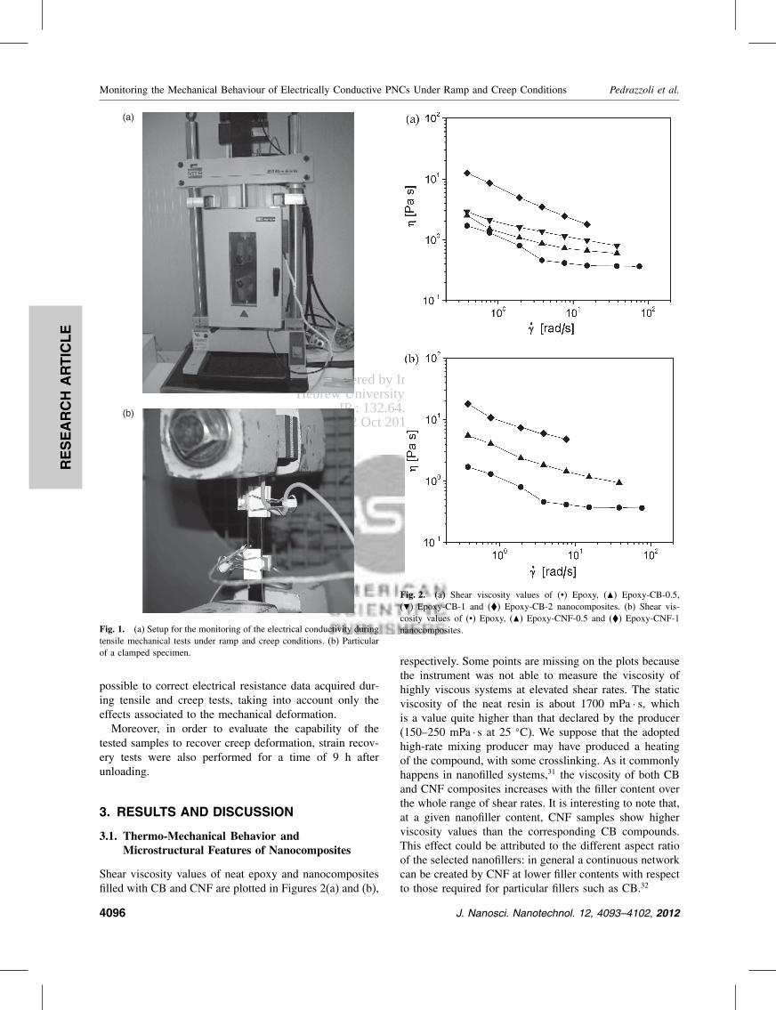
Delivered by Ingenta toHebrew University of Jerusalem
IP 132645431Mon 22 Oct 2012 171546
RESEARCH
ARTIC
LE
Monitoring the Mechanical Behaviour of Electrically Conductive PNCs Under Ramp and Creep Conditions Pedrazzoli et al
(a)
(b)
Fig 1 (a) Setup for the monitoring of the electrical conductivity duringtensile mechanical tests under ramp and creep conditions (b) Particularof a clamped specimen
possible to correct electrical resistance data acquired dur-ing tensile and creep tests taking into account only theeffects associated to the mechanical deformationMoreover in order to evaluate the capability of the
tested samples to recover creep deformation strain recov-ery tests were also performed for a time of 9 h afterunloading
3 RESULTS AND DISCUSSION
31 Thermo-Mechanical Behavior andMicrostructural Features of Nanocomposites
Shear viscosity values of neat epoxy and nanocompositesfilled with CB and CNF are plotted in Figures 2(a) and (b)
Fig 2 (a) Shear viscosity values of (bull) Epoxy () Epoxy-CB-05() Epoxy-CB-1 and () Epoxy-CB-2 nanocomposites (b) Shear vis-cosity values of (bull) Epoxy () Epoxy-CNF-05 and () Epoxy-CNF-1nanocomposites
respectively Some points are missing on the plots becausethe instrument was not able to measure the viscosity ofhighly viscous systems at elevated shear rates The staticviscosity of the neat resin is about 1700 mPa middot s whichis a value quite higher than that declared by the producer(150ndash250 mPa middot s at 25 C) We suppose that the adoptedhigh-rate mixing producer may have produced a heatingof the compound with some crosslinking As it commonlyhappens in nanofilled systems31 the viscosity of both CBand CNF composites increases with the filler content overthe whole range of shear rates It is interesting to note thatat a given nanofiller content CNF samples show higherviscosity values than the corresponding CB compoundsThis effect could be attributed to the different aspect ratioof the selected nanofillers in general a continuous networkcan be created by CNF at lower filler contents with respectto those required for particular fillers such as CB32
4096 J Nanosci Nanotechnol 12 4093ndash4102 2012
Delivered by Ingenta toHebrew University of Jerusalem
IP 132645431Mon 22 Oct 2012 171546
RESEARCH
ARTIC
LE
Pedrazzoli et al Monitoring the Mechanical Behaviour of Electrically Conductive PNCs Under Ramp and Creep Conditions
(a)
(b)
(c)
(d)
(e)
Fig 3 ESEM images of the fracture surfaces of (a) Epoxy (b) Epoxy-CB-05 (c) Epoxy-CB-3 (d) Epoxy-CNF-2 and (e) Epoxy-CBCNF-9010-2 nanocomposites
Information on the dependency of the morphology fromthe filler content and type have been collected by electronmicroscopy FESEM micrographs of neat resin Epoxy-CB-05 Epoxy-CB-3 Epoxy-CNF-2 and Epoxy-CBCNF-9010-2 samples are shown in Figures 3(a)ndash(e) As oftenreported in the scientific literature the fracture surfaceof neat epoxy appears quite smooth (Fig 3(a)) whilethe microstructure of CB nanomodified systems is char-acterized by the presence of primary particles arranged inaggregates and agglomerates homogeneously distributedwithin the polymer matrix Epoxy-CB-05 system is char-acterized by the presence of tiny and pale primary parti-cles with average diameter of about 30 nm organized inagglomerates of about 150 nm Epoxy-CB-3 system man-ifests a higher particle density and a higher tendency ofthe particles to form agglomerates In fact the agglom-erates are larger in size with respect to the systems atlower nanofiller content (about 250 nm) Epoxy-CNF-2system exhibits a rather complex microstructure Evenif some cavities due to fiber-matrix debonding phenom-ena are detectable on the fracture surface (Fig 3(d))it is very difficult to assess the presence of the nanofi-bres and to have information about their dispersion stateAlso in the Epoxy-CBCNF-9010-2 ternary composite itis rather difficult to detect the presence of nanofibres(Fig 3(e)) Table III summarizes the average dimension ofthe agglomerates of CB nanofilled systems As mentionedbefore the size of the agglomerates tends to increasewith the nanofiller content and Epoxy-CBCNF-9010-2presents an agglomerate size very similar to that of Epoxy-CB-2 composite As often reported for particulate fillednanocomposites33 as the filler amount increases the meaninterparticle distance diminishes and the probability ofaggregation is therefore enhancedTable IV summarize glass transition temperatures of
neat epoxy and relative nanocomposites collected duringthe first (Tg1) and second (Tg2) heating scans of DSC testsIn agreement with the producerrsquos data sheet neat resinshows Tg1 and Tg2 values of 82
C and 89 C respectivelyIf CB and CNF based nanocomposites are compared atthe same filler content no substantial differences can befound In fact Tg1 and Tg2 values increase for both mate-rials until a nanofiller concentration of 1 wt and thenit starts to decrease reaching a minimum for a nanofilleramount of 3 wt A similar trend has been previouslyobserved and reported by our group for various nanofilled
Table III Average dimension of the agglomerates detected on thetested samples
Sample Avg agglomerates size (nm)
Epoxy-CB-05 148plusmn12Epoxy-CB-1 144plusmn50Epoxy-CB-2 171plusmn28Epoxy-CB-3 252plusmn82Epoxy-CBCNF-9010-2 157plusmn29
J Nanosci Nanotechnol 12 4093ndash4102 2012 4097
Delivered by Ingenta toHebrew University of Jerusalem
IP 132645431Mon 22 Oct 2012 171546
RESEARCH
ARTIC
LE
Monitoring the Mechanical Behaviour of Electrically Conductive PNCs Under Ramp and Creep Conditions Pedrazzoli et al
Table IV Glass transition values of neat Epoxy and relative nanocom-posites from DSC tests Tg1 and Tg2 refer to the first and the secondheating cycle respectively
Sample Tg1 (C) Tg2 (C)
Epoxy 820 887
Epoxy-CB-05 825 894Epoxy-CB-1 842 905Epoxy-CB-2 813 883Epoxy-CB-3 802 882
Epoxy-CNF-05 825 892Epoxy-CNF-1 855 925Epoxy-CNF-2 822 890Epoxy-CNF-3 789 878
thermosets934ndash37 It could be hypothesized that for elevatedfiller amounts the crosslinking process is partially hinderedby the nanofiller In other words the observed Tg trendscould be explained considering the occurrence of two con-current phenomena as the filler content increases the chainblocking effect is likely to increase thus inducing a slightTg increase while at the same time polymer-filler chemi-cal interactions and the viscosity increase may reduce thecrosslinking degree of the matrix with a consequent reduc-tion of its TgRepresentative stressndashstrain curves of quasi-static ramp
tensile tests on neat epoxy and of CB filled nanocompos-ites are reported in Figure 4 while the most importantmechanical parameters are collected in Table V As oftenobserved with nanofilled systems3839 the elastic modu-lus of both CB and CNF nanocomposites progressivelyincreases with the filler content reaching a maximum fora nanofiller content of 3 wt In particular an increase of13 and 25 can be observed with respect to the neatepoxy resin for CNF and CB systems respectively Foras concern ultimate mechanical properties such as stressand strain at break values for both nanofillers a similar
Fig 4 Representative stressndashstrain curves of quasi-static tensile ramptests of neat epoxy and Epoxy-CB-x nanocomposites (x = 1ndash3 wt)
Table V Quasi-static tensile properties of neat Epoxy Epoxy-CB-x andEpoxy-CNF-x (x = 05 1 2 3 wt) nanocomposites
Sample E (GPa) b (MPa) b ()
Epoxy 303plusmn017 596plusmn08 53plusmn01
Epoxy-CB-05 296plusmn004 674plusmn17 57plusmn02Epoxy-CB-1 323plusmn011 697plusmn04 57plusmn01Epoxy-CB-2 361plusmn010 587plusmn05 42plusmn01Epoxy-CB-3 380plusmn015 550plusmn05 40plusmn01
Epoxy-CNF-05 285plusmn005 624plusmn04 49plusmn01Epoxy-CNF-1 310plusmn008 620plusmn23 56plusmn 02Epoxy-CNF-2 331plusmn005 502plusmn24 35plusmn01Epoxy-CNF-3 342plusmn010 447plusmn15 28plusmn01
trend can be observed with a maximum for a concen-tration of 1 wt The reduction of the tensile propertiesat break at elevated filler contents is more pronouncedwhen CNFs are utilized As previously reported by ourgroup233ndash3540 the progressive embrittlement of nanocom-posite systems at elevated filler amounts could be inducedby nanofiller aggregation If ternary systems with a totalnanofiller amount of 2 wt are considered (Table VI) itcan be concluded that both elastic modulus and ultimatetensile properties follow a rule of mixture
32 Electrical Resistivity of Nanocomposites
In Figure 5(a) the electrical resistivity of the neat epoxyand of nanocomposites is plotted as a function of thecontent of CB or CNF nanofillers The electrical resistiv-ity of the neat matrix is about 1016 middot cm in the typi-cal range generally reported for epoxy resins41 CB fillednanocomposites show a percolation threshold at a fillerconcentration between 1 and 2 wt with a resistivitydrop of more than eight orders of magnitude from 1 to 2wt reaching a plateau value at around 103 middot cm fornanofiller contents higher than 2 wt On the other handCNF based nanocomposites show a percolation thresholdlower than 05 wt For both fillers the electrical resis-tivity diminishes down to about 104 middot cm for a fillercontent of 4 wt As reported in literature1114 it is prob-able that the higher aspect ratio of CNF with respect toCB nanoparticles leads the formation of a conductive path
Table VI Quasi-static tensile properties of the nanocomposites con-taining both CB and CNF with a total nanofiller content of 2 wt
Sample E (GPa) b (MPa) b ()
Epoxy-CNF-2 331plusmn005 502plusmn24 35plusmn01Epoxy-CBCNF-2080-2 330plusmn010 516plusmn12 36plusmn01Epoxy-CBCNF-5050-2 338plusmn005 528plusmn13 37plusmn01Epoxy-CBCNF-6040-2 337plusmn008 546plusmn15 38plusmn01Epoxy-CBCNF-7030-2 340plusmn012 551plusmn11 39plusmn01Epoxy-CBCNF-8020-2 354plusmn010 578plusmn13 40plusmn01Epoxy-CBCNF-9010-2 358plusmn010 586plusmn15 41plusmn01Epoxy-CB-2 361plusmn010 587plusmn05 42plusmn01
4098 J Nanosci Nanotechnol 12 4093ndash4102 2012
Delivered by Ingenta toHebrew University of Jerusalem
IP 132645431Mon 22 Oct 2012 171546
RESEARCH
ARTIC
LE
Pedrazzoli et al Monitoring the Mechanical Behaviour of Electrically Conductive PNCs Under Ramp and Creep Conditions
Fig 5 (a) Electrical resistivity as a function of the nanofiller contentfor () Epoxy-CB-x nanocomposites (x = 1ndash5 wt) (bull) Epoxy-CNF-xnanocomposites (x = 1ndash4 wt) (b) Electrical resistivity as a functionof the CBCNF ratio for nanocomposites with () 05 wt () 1 wt(bull) 2 wt () 3 wt total amounts of nanofillers
at lower filler loadings but after the percolation thresh-old the contribution of the two nanofillers on the electri-cal conductivity of the composites is practically the sameAccording to the literature data matrices with an elec-trical resistivity as low as 104 middot cm seem suitable forelectrical monitoring1842ndash44 therefore both CB and CNFnanocomposites at filler concentrations higher than 2 wtcould be considered as good candidates for self-monitoringapplicationsIn Figure 5(b) the electrical resistivity of the nanocom-
posite systems containing both CB and CNF are plottedas a function of CB relative amount In most cases it canbe seen how electrical resistivity roughly follows the ruleof mixtures Interestingly a negative deviation from lin-earity can be detected for the systems with a total fillercontent of 2 wt Resistivity data follow a linear trenduntil a CB relative amount of 60ndash70 is reached and thena minimum is detected for a CBCNF ratio of 9010 Asreported by Sumfleth et al16 it can be hypothesized thatthe fine dispersion of CB and CNF leads to the forma-tion of co-supporting networks in which CB agglomerates
are interconnected by CNF dispersed in the interparticleregion Under these conditions the formation of a conduc-tive path within the matrix is favouredOn the basis of thermo-mechanical and electrical char-
acterization it emerges that 2 wt nanofilled systems dis-play good conductivity values with acceptable values oftensile strength and glass transition temperature There-fore Epoxy-CBCNF-9010-2 sample was chosen for thesubsequent characterization of the electrical monitoring oftensile mechanical behavior under ramp and creep loadingconditions
33 Monitoring the Mechanical ResponseUnder Ramp and Creep ConditionsThrough Electrical Resistivity
Ramp (ie constant strain rate) tensile tests were per-formed on Epoxy-CBCNF-9010-2 samples Stress-straincurve and the relative electrical resistance variation(RR0 during tensile test on the nanocomposite samplesare compared in Figure 6 It can be noticed that RR0
follows a linear trend for small deformations (ie lowerthan 05) and that for higher strain levels the slope ofthe curves slightly decreases When the final failure isapproached a sudden increase of RR0 values probablydue to a rapid damage evolution within the matrix canbe detected As reported by Nanni et al44 the separationbetween conductive particles at an increasing strain resultsin a higher electrical resistance Sensitivity is enhancedsince the conductive particles gradually separate understrain with a consequent enhancement of the electricalresistivity Moreover as the stress at break is approacheda permanent separation between particles occurs due tocracks nucleation with a sudden increase of the resis-tance values It can be therefore concluded that the selectednanocomposite system can be electrically monitored whena ramp load is applied
Fig 6 Stressndashstrain curve and relative resistance variation during ramptensile test on Epoxy-CBCNF-9010-2 sample
J Nanosci Nanotechnol 12 4093ndash4102 2012 4099
Delivered by Ingenta toHebrew University of Jerusalem
IP 132645431Mon 22 Oct 2012 171546
RESEARCH
ARTIC
LE
Monitoring the Mechanical Behaviour of Electrically Conductive PNCs Under Ramp and Creep Conditions Pedrazzoli et al
Room temperature creep compliance of neat matrix andEpoxy-CBCNF-9010-2 nanocomposite are compared atvarious stress levels in Figure 7(a) while creep compliancedata at 50 C are reported in Figure 7(b) for two differ-ent stress levels Both at room temperature and at 50 Cnanofilled sample manifests an interesting improvement ofthe creep stability with respect to the neat matrix In factboth elastic and viscoelastic components of the creep com-pliance are remarkably reduced by nanofiller introductionAs previously reported3845 the stabilizing effect providedby a nanofiller in a polymer matrix is more evident at ele-vated stress levels or at elevated test temperatures There-fore an appropriate combination of carbon nanofillers canbe exploited for preparing moderately conductive materi-als concurrently enhancing their creep stabilityIn Figure 8 creep compliance and electrical resistance
variation of Epoxy-CBCNF-9010-2 sample are reportedon the same plot for creep tests at various stresses per-formed at room temperature (Fig 8(a)) and at 50 C(Fig 8(b)) At room temperature a sudden increase of the
(a)
(b)
Fig 7 Comparison of the creep compliance of the neat matrix (- -) andof the Epoxy-CBCNF-9010-2 nanocomposite (mdash) at (a) room temper-ature and (b) at 50 C for different applied stresses
Fig 8 Creep compliance and resistance variation during creep loadingof Epoxy-CBCNF-9010-2 sample at various applied stresses at (a) roomtemperature and (b) at 50 C
electrical resistance upon load application can be observedproportionally to the stress level It is interesting to notehow RR0 tends to decrease with creep time for appliedstresses of 30 and 40 MPa while at 50 MPa an almostflat plot can be detected At 50 C creep compliance val-ues are noticeably higher than those registered at roomtemperature and a progressive increase of RR0 withtime can be observed regardless the stress level It can betherefore concluded that the creep monitoring capabilityof the selected nanocomposites is strongly affected by theapplied stress and the temperature Different deformationand conduction mechanisms could be tentatively invokedto explain the trend of the electrical resistivity undercreep conditions It is well known that both microstructureand electrical conduction behaviour of polymeric materialsis strongly influenced by time dependent mechanisms46
It can be hypothesized that as a consequence of theinstantaneous application of the creep load the conduc-tive network within the polymer matrix is destroyed anda resistivity increase is observed When the kinetics ofdeformational processes is low (ie at low temperatures
4100 J Nanosci Nanotechnol 12 4093ndash4102 2012
Delivered by Ingenta toHebrew University of Jerusalem
IP 132645431Mon 22 Oct 2012 171546
RESEARCH
ARTIC
LE
Pedrazzoli et al Monitoring the Mechanical Behaviour of Electrically Conductive PNCs Under Ramp and Creep Conditions
andor at low stresses) nanoparticles are able to re-form aconductive network thus inducing a progressive decreaseof the electrical resistance On the other hand at elevatedcreep stresses andor temperatures the higher kinetics ofthe deformational processes may hinder interparticle inter-actions and the subsequent re-formation of the conductivepath with a progressive increase of RR0 values withtime In any case further investigations are needed to gaina better comprehension of the observed phenomenonIn order to investigate the potential of the selected
nanocomposite system for monitoring the strain recov-ery processes after creep loading some tests were per-formed In Figure 9(a) the plots of the deformation of theEpoxy-CBCNF-9010-2 sample during creep and recov-ery tests performed both at room temperature and at50 C are reported while in Figure 9(b) the correspon-dent relative resistance values are represented When the
(a)
(b)
Fig 9 (a) Relative deformation and (b) relative values of the electricalresistance of the Epoxy-CBCNF-9010-2 sample for a creep test andfollowing recovery performed at room temperature and at 50 C (appliedstress of 20 MPa)
creep test is performed at room temperature the sampleis able to recover practically all the applied deformationafter unloading while a remarkable residual deformationremains at the end of the recovery stage if the test is car-ried out at 50 C It is interesting to note how the electricalresistance measured at the end of the recovery at 20 Cis similar to the RR0 value registered before the appli-cation of the load On the other hand at 50 C the finalresistance is considerably higher than that determined atthe beginning of the creep stage This permanent increaseof the electrical resistance registered at elevated tempera-ture is clearly related to the permanent deformation andordamage evolution within the epoxy matrix accumulatedduring the loading stage
4 CONCLUSIONS
Electrically conductive nanocomposites were prepared byadding various amounts of carbon black and carbon nanofi-bres in an epoxy matrix The mechanical characterizationof the resulting composites highlighted how both CB andCNF were able to improve the elastic modulus of the neatmatrix with a positive effect on its ultimate properties upto a filler content of 1 wt The introduction of both thenanofillers lead to a dramatic decrease of the electricalresistivity down to values of 103ndash104 middotcm for filler load-ings higher than 2 wt Moreover a positive synergisticeffect was detected for epoxy systems containing a totalnanofiller amount of 2 wt with a relative CBCNF ratioof 9010The monitoring of tensile tests under ramp conditions
highlighted a direct correlation between the tensile strainand the increase of the electrical resistance over the wholeduration of the tests Monitoring of tensile creep testsevidenced a complex electrical response depending onthe temperature and applied stress levels Moreover theepoxy nanocomposite under investigation allowed also anelectrical monitoring of the strain recovery process afterunloading These results are encouraging for a possibleapplication of the nanomodified epoxy for the prepara-tion of fibre reinforced structural composites with damage-sensing capabilities
References and Notes
1 J H Koo Polymer Nanocomposite Process Characterization andApplications McGraw-Hill New York (2006)
2 F Bondioli A Dorigato P Fabbri M Messori and A PegorettiPolym Eng Sci 48 448 (2008)
3 O Starkova J L Yang and Z Zhang Compos Sci Technol67 2691 (2007)
4 Z Zhang J L Yang and K Friedrich Polymer 45 3481 (2004)5 W J Choi S H Kim Y J Kim and S C Kim Polymer 45 6045
(2004)6 M Gorrasi M Tortora and G Vittoria J Polym Sci Part B
Polym Phys 43 2454 (2005)
J Nanosci Nanotechnol 12 4093ndash4102 2012 4101
Delivered by Ingenta toHebrew University of Jerusalem
IP 132645431Mon 22 Oct 2012 171546
RESEARCH
ARTIC
LE
Monitoring the Mechanical Behaviour of Electrically Conductive PNCs Under Ramp and Creep Conditions Pedrazzoli et al
7 C Zhao H Qin F Gong M Feng S Zhang and M Yang PolymDegrad Stab 87 183 (2005)
8 C F Ou and M C Hsu J Polym Res 14 373 (2007)9 A Pegoretti A Dorigato and A Penati Eur Polym J 44 1662
(2008)10 M Traina A Pegoretti and A Penati J Appl Polym Sci 106 2065
(2007)11 Z J Fan C Zheng T Wei Y C Zhang and G L Luo Polym
Eng Sci 49 2041 (2009)12 S Kumar L L Sun S Caceres B Li W Wood A Perugini R G
Maguire and W H Zhong Nanotechnology 21 105702 (2010)13 J H Lee Y K Jang C E Hong N H Kim P Li and H K Lee
J Power Sources 193 523 (2009)14 J Li P S Wong and J K Kim Materials Science and Engineer-
ing a-Structural Materials Properties Microstructure and Processing483ndash84 660 (2008)
15 P C Ma M Y Liu H Zhang S Q Wang R Wang K WangY K Wong B Z Tang S H Hong K W Paik and J K KimAcs Applied Materials amp Interfaces 1 1090 (2009)
16 J Sumfleth X C Adroher and K Schulte J Mater Sci 44 3241(2009)
17 M Tait A Pegoretti A Dorigato and K Kalaitzidou Carbon49 4280 (2011)
18 L Boumleger M H G Wichmann L O Meyer and K SchulteCompos Sci Technol 68 1886 (2008)
19 J C Abry S Bochard A Chateauminois M Salvia and G GiraudCompos Sci Technol 59 925 (1999)
20 J C Abry Y K Choi A Chateauminois B Dalloz G Giraud andM Salvia Compos Sci Technol 61 855 (2001)
21 P E Irving and C Thiagarajan Smart Materials amp Structures 7 456(1998)
22 A S Kaddour F A R Alsalehi S T S Alhassani and M JHinton Compos Sci Technol 51 377 (1994)
23 M Kupke K Schulte and R Schuler Compos Sci Technol 61 837(2001)
24 D C Seo and J J Lee Compos Struct 47 525 (1999)25 A Todoroki H Kobayashi and K Matuura Jsme International
Journal Series a-Mechanics and Material Engineering 38 524(1995)
26 A Todoroki K Omagari Y Shimamura and H KobayashiCompos Sci Technol 66 1539 (2006)
27 A Todoroki M Tanaka Y Shimamura and H KobayashiAdv Compos Mater 13 107 (2004)
28 A Todoroki and Y Tanaka Compos Sci Technol 62 629(2002)
29 N Muto Y Arai S G Shin H Matsubara H Yanagida M Sugitaand T Nakatsuji Compos Sci Technol 61 875 (2001)
30 E T Thostenson and T W Chou Advanced Materials 18 2837(2006)
31 A Dorigato S Morandi and A Pegoretti J Compos Mater(in press)
32 J Sumfleth S T Buschhorn and K Schulte J Mater Sci 46 659(2010)
33 A Dorigato M DrsquoAmato and A Pegoretti J Polym Res (in press)34 A Dorigato A Pegoretti F Bondioli and M Messori Composite
Interfaces 17 873 (2010)35 A Dorigato and A Pegoretti J Nanopart Res 13 2429 (2011)36 A Dorigato A Pegoretti and A Penati J Reinf Plast Compos
30 325 (2011)37 A Dorigato A Pegoretti and M Quaresimin Mater Sci Eng A
528 6324 (2011)38 A Dorigato and A Pegoretti Polym Int 59 719 (2010)39 A Dorigato L Fambri A Pegoretti M Slouf and J Kolarik
J Appl Polym Sci 119 3393 (2011)40 F Bondioli A Dorigato P Fabbri M Messori and A Pegoretti
J Appl Polym Sci 112 1045 (2009)41 Y Choi K Sugimoto S Song Y Gotoh Y Ohkoshi and M Endo
Carbon 43 2199 (2005)42 V Kostopoulos A Vavouliotis P Karapappas P Tsotra and
A Paipetis J Intell Mater Syst Struct 20 1025 (2009)43 C D Liu L F Cheng X G Luan B Li and J Zhou Mater Lett
62 3922 (2008)44 F Nanni G Ruscito D Puglia A Terenzi J M Kenny and
G Gusmano Compos Sci Technol 71 1 (2011)45 A Dorigato A Pegoretti and J Kolarik Polym Compos 31 1947
(2010)46 C Zhang P Wang C Ma G Wu and M Sumita Polymer 47 466
(2006)
Received 27 September 2011 Accepted 9 November 2011
4102 J Nanosci Nanotechnol 12 4093ndash4102 2012
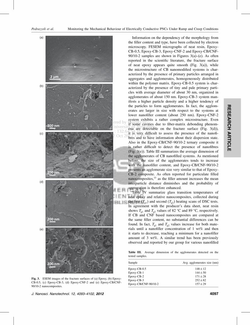
Delivered by Ingenta toHebrew University of Jerusalem
IP 132645431Mon 22 Oct 2012 171546
RESEARCH
ARTIC
LE
Pedrazzoli et al Monitoring the Mechanical Behaviour of Electrically Conductive PNCs Under Ramp and Creep Conditions
(a)
(b)
(c)
(d)
(e)
Fig 3 ESEM images of the fracture surfaces of (a) Epoxy (b) Epoxy-CB-05 (c) Epoxy-CB-3 (d) Epoxy-CNF-2 and (e) Epoxy-CBCNF-9010-2 nanocomposites
Information on the dependency of the morphology fromthe filler content and type have been collected by electronmicroscopy FESEM micrographs of neat resin Epoxy-CB-05 Epoxy-CB-3 Epoxy-CNF-2 and Epoxy-CBCNF-9010-2 samples are shown in Figures 3(a)ndash(e) As oftenreported in the scientific literature the fracture surfaceof neat epoxy appears quite smooth (Fig 3(a)) whilethe microstructure of CB nanomodified systems is char-acterized by the presence of primary particles arranged inaggregates and agglomerates homogeneously distributedwithin the polymer matrix Epoxy-CB-05 system is char-acterized by the presence of tiny and pale primary parti-cles with average diameter of about 30 nm organized inagglomerates of about 150 nm Epoxy-CB-3 system man-ifests a higher particle density and a higher tendency ofthe particles to form agglomerates In fact the agglom-erates are larger in size with respect to the systems atlower nanofiller content (about 250 nm) Epoxy-CNF-2system exhibits a rather complex microstructure Evenif some cavities due to fiber-matrix debonding phenom-ena are detectable on the fracture surface (Fig 3(d))it is very difficult to assess the presence of the nanofi-bres and to have information about their dispersion stateAlso in the Epoxy-CBCNF-9010-2 ternary composite itis rather difficult to detect the presence of nanofibres(Fig 3(e)) Table III summarizes the average dimension ofthe agglomerates of CB nanofilled systems As mentionedbefore the size of the agglomerates tends to increasewith the nanofiller content and Epoxy-CBCNF-9010-2presents an agglomerate size very similar to that of Epoxy-CB-2 composite As often reported for particulate fillednanocomposites33 as the filler amount increases the meaninterparticle distance diminishes and the probability ofaggregation is therefore enhancedTable IV summarize glass transition temperatures of
neat epoxy and relative nanocomposites collected duringthe first (Tg1) and second (Tg2) heating scans of DSC testsIn agreement with the producerrsquos data sheet neat resinshows Tg1 and Tg2 values of 82
C and 89 C respectivelyIf CB and CNF based nanocomposites are compared atthe same filler content no substantial differences can befound In fact Tg1 and Tg2 values increase for both mate-rials until a nanofiller concentration of 1 wt and thenit starts to decrease reaching a minimum for a nanofilleramount of 3 wt A similar trend has been previouslyobserved and reported by our group for various nanofilled
Table III Average dimension of the agglomerates detected on thetested samples
Sample Avg agglomerates size (nm)
Epoxy-CB-05 148plusmn12Epoxy-CB-1 144plusmn50Epoxy-CB-2 171plusmn28Epoxy-CB-3 252plusmn82Epoxy-CBCNF-9010-2 157plusmn29
J Nanosci Nanotechnol 12 4093ndash4102 2012 4097
Delivered by Ingenta toHebrew University of Jerusalem
IP 132645431Mon 22 Oct 2012 171546
RESEARCH
ARTIC
LE
Monitoring the Mechanical Behaviour of Electrically Conductive PNCs Under Ramp and Creep Conditions Pedrazzoli et al
Table IV Glass transition values of neat Epoxy and relative nanocom-posites from DSC tests Tg1 and Tg2 refer to the first and the secondheating cycle respectively
Sample Tg1 (C) Tg2 (C)
Epoxy 820 887
Epoxy-CB-05 825 894Epoxy-CB-1 842 905Epoxy-CB-2 813 883Epoxy-CB-3 802 882
Epoxy-CNF-05 825 892Epoxy-CNF-1 855 925Epoxy-CNF-2 822 890Epoxy-CNF-3 789 878
thermosets934ndash37 It could be hypothesized that for elevatedfiller amounts the crosslinking process is partially hinderedby the nanofiller In other words the observed Tg trendscould be explained considering the occurrence of two con-current phenomena as the filler content increases the chainblocking effect is likely to increase thus inducing a slightTg increase while at the same time polymer-filler chemi-cal interactions and the viscosity increase may reduce thecrosslinking degree of the matrix with a consequent reduc-tion of its TgRepresentative stressndashstrain curves of quasi-static ramp
tensile tests on neat epoxy and of CB filled nanocompos-ites are reported in Figure 4 while the most importantmechanical parameters are collected in Table V As oftenobserved with nanofilled systems3839 the elastic modu-lus of both CB and CNF nanocomposites progressivelyincreases with the filler content reaching a maximum fora nanofiller content of 3 wt In particular an increase of13 and 25 can be observed with respect to the neatepoxy resin for CNF and CB systems respectively Foras concern ultimate mechanical properties such as stressand strain at break values for both nanofillers a similar
Fig 4 Representative stressndashstrain curves of quasi-static tensile ramptests of neat epoxy and Epoxy-CB-x nanocomposites (x = 1ndash3 wt)
Table V Quasi-static tensile properties of neat Epoxy Epoxy-CB-x andEpoxy-CNF-x (x = 05 1 2 3 wt) nanocomposites
Sample E (GPa) b (MPa) b ()
Epoxy 303plusmn017 596plusmn08 53plusmn01
Epoxy-CB-05 296plusmn004 674plusmn17 57plusmn02Epoxy-CB-1 323plusmn011 697plusmn04 57plusmn01Epoxy-CB-2 361plusmn010 587plusmn05 42plusmn01Epoxy-CB-3 380plusmn015 550plusmn05 40plusmn01
Epoxy-CNF-05 285plusmn005 624plusmn04 49plusmn01Epoxy-CNF-1 310plusmn008 620plusmn23 56plusmn 02Epoxy-CNF-2 331plusmn005 502plusmn24 35plusmn01Epoxy-CNF-3 342plusmn010 447plusmn15 28plusmn01
trend can be observed with a maximum for a concen-tration of 1 wt The reduction of the tensile propertiesat break at elevated filler contents is more pronouncedwhen CNFs are utilized As previously reported by ourgroup233ndash3540 the progressive embrittlement of nanocom-posite systems at elevated filler amounts could be inducedby nanofiller aggregation If ternary systems with a totalnanofiller amount of 2 wt are considered (Table VI) itcan be concluded that both elastic modulus and ultimatetensile properties follow a rule of mixture
32 Electrical Resistivity of Nanocomposites
In Figure 5(a) the electrical resistivity of the neat epoxyand of nanocomposites is plotted as a function of thecontent of CB or CNF nanofillers The electrical resistiv-ity of the neat matrix is about 1016 middot cm in the typi-cal range generally reported for epoxy resins41 CB fillednanocomposites show a percolation threshold at a fillerconcentration between 1 and 2 wt with a resistivitydrop of more than eight orders of magnitude from 1 to 2wt reaching a plateau value at around 103 middot cm fornanofiller contents higher than 2 wt On the other handCNF based nanocomposites show a percolation thresholdlower than 05 wt For both fillers the electrical resis-tivity diminishes down to about 104 middot cm for a fillercontent of 4 wt As reported in literature1114 it is prob-able that the higher aspect ratio of CNF with respect toCB nanoparticles leads the formation of a conductive path
Table VI Quasi-static tensile properties of the nanocomposites con-taining both CB and CNF with a total nanofiller content of 2 wt
Sample E (GPa) b (MPa) b ()
Epoxy-CNF-2 331plusmn005 502plusmn24 35plusmn01Epoxy-CBCNF-2080-2 330plusmn010 516plusmn12 36plusmn01Epoxy-CBCNF-5050-2 338plusmn005 528plusmn13 37plusmn01Epoxy-CBCNF-6040-2 337plusmn008 546plusmn15 38plusmn01Epoxy-CBCNF-7030-2 340plusmn012 551plusmn11 39plusmn01Epoxy-CBCNF-8020-2 354plusmn010 578plusmn13 40plusmn01Epoxy-CBCNF-9010-2 358plusmn010 586plusmn15 41plusmn01Epoxy-CB-2 361plusmn010 587plusmn05 42plusmn01
4098 J Nanosci Nanotechnol 12 4093ndash4102 2012
Delivered by Ingenta toHebrew University of Jerusalem
IP 132645431Mon 22 Oct 2012 171546
RESEARCH
ARTIC
LE
Pedrazzoli et al Monitoring the Mechanical Behaviour of Electrically Conductive PNCs Under Ramp and Creep Conditions
Fig 5 (a) Electrical resistivity as a function of the nanofiller contentfor () Epoxy-CB-x nanocomposites (x = 1ndash5 wt) (bull) Epoxy-CNF-xnanocomposites (x = 1ndash4 wt) (b) Electrical resistivity as a functionof the CBCNF ratio for nanocomposites with () 05 wt () 1 wt(bull) 2 wt () 3 wt total amounts of nanofillers
at lower filler loadings but after the percolation thresh-old the contribution of the two nanofillers on the electri-cal conductivity of the composites is practically the sameAccording to the literature data matrices with an elec-trical resistivity as low as 104 middot cm seem suitable forelectrical monitoring1842ndash44 therefore both CB and CNFnanocomposites at filler concentrations higher than 2 wtcould be considered as good candidates for self-monitoringapplicationsIn Figure 5(b) the electrical resistivity of the nanocom-
posite systems containing both CB and CNF are plottedas a function of CB relative amount In most cases it canbe seen how electrical resistivity roughly follows the ruleof mixtures Interestingly a negative deviation from lin-earity can be detected for the systems with a total fillercontent of 2 wt Resistivity data follow a linear trenduntil a CB relative amount of 60ndash70 is reached and thena minimum is detected for a CBCNF ratio of 9010 Asreported by Sumfleth et al16 it can be hypothesized thatthe fine dispersion of CB and CNF leads to the forma-tion of co-supporting networks in which CB agglomerates
are interconnected by CNF dispersed in the interparticleregion Under these conditions the formation of a conduc-tive path within the matrix is favouredOn the basis of thermo-mechanical and electrical char-
acterization it emerges that 2 wt nanofilled systems dis-play good conductivity values with acceptable values oftensile strength and glass transition temperature There-fore Epoxy-CBCNF-9010-2 sample was chosen for thesubsequent characterization of the electrical monitoring oftensile mechanical behavior under ramp and creep loadingconditions
33 Monitoring the Mechanical ResponseUnder Ramp and Creep ConditionsThrough Electrical Resistivity
Ramp (ie constant strain rate) tensile tests were per-formed on Epoxy-CBCNF-9010-2 samples Stress-straincurve and the relative electrical resistance variation(RR0 during tensile test on the nanocomposite samplesare compared in Figure 6 It can be noticed that RR0
follows a linear trend for small deformations (ie lowerthan 05) and that for higher strain levels the slope ofthe curves slightly decreases When the final failure isapproached a sudden increase of RR0 values probablydue to a rapid damage evolution within the matrix canbe detected As reported by Nanni et al44 the separationbetween conductive particles at an increasing strain resultsin a higher electrical resistance Sensitivity is enhancedsince the conductive particles gradually separate understrain with a consequent enhancement of the electricalresistivity Moreover as the stress at break is approacheda permanent separation between particles occurs due tocracks nucleation with a sudden increase of the resis-tance values It can be therefore concluded that the selectednanocomposite system can be electrically monitored whena ramp load is applied
Fig 6 Stressndashstrain curve and relative resistance variation during ramptensile test on Epoxy-CBCNF-9010-2 sample
J Nanosci Nanotechnol 12 4093ndash4102 2012 4099
Delivered by Ingenta toHebrew University of Jerusalem
IP 132645431Mon 22 Oct 2012 171546
RESEARCH
ARTIC
LE
Monitoring the Mechanical Behaviour of Electrically Conductive PNCs Under Ramp and Creep Conditions Pedrazzoli et al
Room temperature creep compliance of neat matrix andEpoxy-CBCNF-9010-2 nanocomposite are compared atvarious stress levels in Figure 7(a) while creep compliancedata at 50 C are reported in Figure 7(b) for two differ-ent stress levels Both at room temperature and at 50 Cnanofilled sample manifests an interesting improvement ofthe creep stability with respect to the neat matrix In factboth elastic and viscoelastic components of the creep com-pliance are remarkably reduced by nanofiller introductionAs previously reported3845 the stabilizing effect providedby a nanofiller in a polymer matrix is more evident at ele-vated stress levels or at elevated test temperatures There-fore an appropriate combination of carbon nanofillers canbe exploited for preparing moderately conductive materi-als concurrently enhancing their creep stabilityIn Figure 8 creep compliance and electrical resistance
variation of Epoxy-CBCNF-9010-2 sample are reportedon the same plot for creep tests at various stresses per-formed at room temperature (Fig 8(a)) and at 50 C(Fig 8(b)) At room temperature a sudden increase of the
(a)
(b)
Fig 7 Comparison of the creep compliance of the neat matrix (- -) andof the Epoxy-CBCNF-9010-2 nanocomposite (mdash) at (a) room temper-ature and (b) at 50 C for different applied stresses
Fig 8 Creep compliance and resistance variation during creep loadingof Epoxy-CBCNF-9010-2 sample at various applied stresses at (a) roomtemperature and (b) at 50 C
electrical resistance upon load application can be observedproportionally to the stress level It is interesting to notehow RR0 tends to decrease with creep time for appliedstresses of 30 and 40 MPa while at 50 MPa an almostflat plot can be detected At 50 C creep compliance val-ues are noticeably higher than those registered at roomtemperature and a progressive increase of RR0 withtime can be observed regardless the stress level It can betherefore concluded that the creep monitoring capabilityof the selected nanocomposites is strongly affected by theapplied stress and the temperature Different deformationand conduction mechanisms could be tentatively invokedto explain the trend of the electrical resistivity undercreep conditions It is well known that both microstructureand electrical conduction behaviour of polymeric materialsis strongly influenced by time dependent mechanisms46
It can be hypothesized that as a consequence of theinstantaneous application of the creep load the conduc-tive network within the polymer matrix is destroyed anda resistivity increase is observed When the kinetics ofdeformational processes is low (ie at low temperatures
4100 J Nanosci Nanotechnol 12 4093ndash4102 2012
Delivered by Ingenta toHebrew University of Jerusalem
IP 132645431Mon 22 Oct 2012 171546
RESEARCH
ARTIC
LE
Pedrazzoli et al Monitoring the Mechanical Behaviour of Electrically Conductive PNCs Under Ramp and Creep Conditions
andor at low stresses) nanoparticles are able to re-form aconductive network thus inducing a progressive decreaseof the electrical resistance On the other hand at elevatedcreep stresses andor temperatures the higher kinetics ofthe deformational processes may hinder interparticle inter-actions and the subsequent re-formation of the conductivepath with a progressive increase of RR0 values withtime In any case further investigations are needed to gaina better comprehension of the observed phenomenonIn order to investigate the potential of the selected
nanocomposite system for monitoring the strain recov-ery processes after creep loading some tests were per-formed In Figure 9(a) the plots of the deformation of theEpoxy-CBCNF-9010-2 sample during creep and recov-ery tests performed both at room temperature and at50 C are reported while in Figure 9(b) the correspon-dent relative resistance values are represented When the
(a)
(b)
Fig 9 (a) Relative deformation and (b) relative values of the electricalresistance of the Epoxy-CBCNF-9010-2 sample for a creep test andfollowing recovery performed at room temperature and at 50 C (appliedstress of 20 MPa)
creep test is performed at room temperature the sampleis able to recover practically all the applied deformationafter unloading while a remarkable residual deformationremains at the end of the recovery stage if the test is car-ried out at 50 C It is interesting to note how the electricalresistance measured at the end of the recovery at 20 Cis similar to the RR0 value registered before the appli-cation of the load On the other hand at 50 C the finalresistance is considerably higher than that determined atthe beginning of the creep stage This permanent increaseof the electrical resistance registered at elevated tempera-ture is clearly related to the permanent deformation andordamage evolution within the epoxy matrix accumulatedduring the loading stage
4 CONCLUSIONS
Electrically conductive nanocomposites were prepared byadding various amounts of carbon black and carbon nanofi-bres in an epoxy matrix The mechanical characterizationof the resulting composites highlighted how both CB andCNF were able to improve the elastic modulus of the neatmatrix with a positive effect on its ultimate properties upto a filler content of 1 wt The introduction of both thenanofillers lead to a dramatic decrease of the electricalresistivity down to values of 103ndash104 middotcm for filler load-ings higher than 2 wt Moreover a positive synergisticeffect was detected for epoxy systems containing a totalnanofiller amount of 2 wt with a relative CBCNF ratioof 9010The monitoring of tensile tests under ramp conditions
highlighted a direct correlation between the tensile strainand the increase of the electrical resistance over the wholeduration of the tests Monitoring of tensile creep testsevidenced a complex electrical response depending onthe temperature and applied stress levels Moreover theepoxy nanocomposite under investigation allowed also anelectrical monitoring of the strain recovery process afterunloading These results are encouraging for a possibleapplication of the nanomodified epoxy for the prepara-tion of fibre reinforced structural composites with damage-sensing capabilities
References and Notes
1 J H Koo Polymer Nanocomposite Process Characterization andApplications McGraw-Hill New York (2006)
2 F Bondioli A Dorigato P Fabbri M Messori and A PegorettiPolym Eng Sci 48 448 (2008)
3 O Starkova J L Yang and Z Zhang Compos Sci Technol67 2691 (2007)
4 Z Zhang J L Yang and K Friedrich Polymer 45 3481 (2004)5 W J Choi S H Kim Y J Kim and S C Kim Polymer 45 6045
(2004)6 M Gorrasi M Tortora and G Vittoria J Polym Sci Part B
Polym Phys 43 2454 (2005)
J Nanosci Nanotechnol 12 4093ndash4102 2012 4101
Delivered by Ingenta toHebrew University of Jerusalem
IP 132645431Mon 22 Oct 2012 171546
RESEARCH
ARTIC
LE
Monitoring the Mechanical Behaviour of Electrically Conductive PNCs Under Ramp and Creep Conditions Pedrazzoli et al
7 C Zhao H Qin F Gong M Feng S Zhang and M Yang PolymDegrad Stab 87 183 (2005)
8 C F Ou and M C Hsu J Polym Res 14 373 (2007)9 A Pegoretti A Dorigato and A Penati Eur Polym J 44 1662
(2008)10 M Traina A Pegoretti and A Penati J Appl Polym Sci 106 2065
(2007)11 Z J Fan C Zheng T Wei Y C Zhang and G L Luo Polym
Eng Sci 49 2041 (2009)12 S Kumar L L Sun S Caceres B Li W Wood A Perugini R G
Maguire and W H Zhong Nanotechnology 21 105702 (2010)13 J H Lee Y K Jang C E Hong N H Kim P Li and H K Lee
J Power Sources 193 523 (2009)14 J Li P S Wong and J K Kim Materials Science and Engineer-
ing a-Structural Materials Properties Microstructure and Processing483ndash84 660 (2008)
15 P C Ma M Y Liu H Zhang S Q Wang R Wang K WangY K Wong B Z Tang S H Hong K W Paik and J K KimAcs Applied Materials amp Interfaces 1 1090 (2009)
16 J Sumfleth X C Adroher and K Schulte J Mater Sci 44 3241(2009)
17 M Tait A Pegoretti A Dorigato and K Kalaitzidou Carbon49 4280 (2011)
18 L Boumleger M H G Wichmann L O Meyer and K SchulteCompos Sci Technol 68 1886 (2008)
19 J C Abry S Bochard A Chateauminois M Salvia and G GiraudCompos Sci Technol 59 925 (1999)
20 J C Abry Y K Choi A Chateauminois B Dalloz G Giraud andM Salvia Compos Sci Technol 61 855 (2001)
21 P E Irving and C Thiagarajan Smart Materials amp Structures 7 456(1998)
22 A S Kaddour F A R Alsalehi S T S Alhassani and M JHinton Compos Sci Technol 51 377 (1994)
23 M Kupke K Schulte and R Schuler Compos Sci Technol 61 837(2001)
24 D C Seo and J J Lee Compos Struct 47 525 (1999)25 A Todoroki H Kobayashi and K Matuura Jsme International
Journal Series a-Mechanics and Material Engineering 38 524(1995)
26 A Todoroki K Omagari Y Shimamura and H KobayashiCompos Sci Technol 66 1539 (2006)
27 A Todoroki M Tanaka Y Shimamura and H KobayashiAdv Compos Mater 13 107 (2004)
28 A Todoroki and Y Tanaka Compos Sci Technol 62 629(2002)
29 N Muto Y Arai S G Shin H Matsubara H Yanagida M Sugitaand T Nakatsuji Compos Sci Technol 61 875 (2001)
30 E T Thostenson and T W Chou Advanced Materials 18 2837(2006)
31 A Dorigato S Morandi and A Pegoretti J Compos Mater(in press)
32 J Sumfleth S T Buschhorn and K Schulte J Mater Sci 46 659(2010)
33 A Dorigato M DrsquoAmato and A Pegoretti J Polym Res (in press)34 A Dorigato A Pegoretti F Bondioli and M Messori Composite
Interfaces 17 873 (2010)35 A Dorigato and A Pegoretti J Nanopart Res 13 2429 (2011)36 A Dorigato A Pegoretti and A Penati J Reinf Plast Compos
30 325 (2011)37 A Dorigato A Pegoretti and M Quaresimin Mater Sci Eng A
528 6324 (2011)38 A Dorigato and A Pegoretti Polym Int 59 719 (2010)39 A Dorigato L Fambri A Pegoretti M Slouf and J Kolarik
J Appl Polym Sci 119 3393 (2011)40 F Bondioli A Dorigato P Fabbri M Messori and A Pegoretti
J Appl Polym Sci 112 1045 (2009)41 Y Choi K Sugimoto S Song Y Gotoh Y Ohkoshi and M Endo
Carbon 43 2199 (2005)42 V Kostopoulos A Vavouliotis P Karapappas P Tsotra and
A Paipetis J Intell Mater Syst Struct 20 1025 (2009)43 C D Liu L F Cheng X G Luan B Li and J Zhou Mater Lett
62 3922 (2008)44 F Nanni G Ruscito D Puglia A Terenzi J M Kenny and
G Gusmano Compos Sci Technol 71 1 (2011)45 A Dorigato A Pegoretti and J Kolarik Polym Compos 31 1947
(2010)46 C Zhang P Wang C Ma G Wu and M Sumita Polymer 47 466
(2006)
Received 27 September 2011 Accepted 9 November 2011
4102 J Nanosci Nanotechnol 12 4093ndash4102 2012
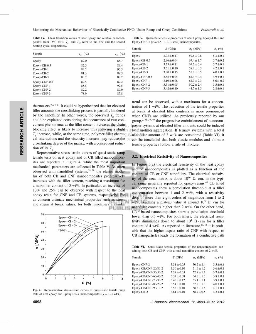
Delivered by Ingenta toHebrew University of Jerusalem
IP 132645431Mon 22 Oct 2012 171546
RESEARCH
ARTIC
LE
Monitoring the Mechanical Behaviour of Electrically Conductive PNCs Under Ramp and Creep Conditions Pedrazzoli et al
Table IV Glass transition values of neat Epoxy and relative nanocom-posites from DSC tests Tg1 and Tg2 refer to the first and the secondheating cycle respectively
Sample Tg1 (C) Tg2 (C)
Epoxy 820 887
Epoxy-CB-05 825 894Epoxy-CB-1 842 905Epoxy-CB-2 813 883Epoxy-CB-3 802 882
Epoxy-CNF-05 825 892Epoxy-CNF-1 855 925Epoxy-CNF-2 822 890Epoxy-CNF-3 789 878
thermosets934ndash37 It could be hypothesized that for elevatedfiller amounts the crosslinking process is partially hinderedby the nanofiller In other words the observed Tg trendscould be explained considering the occurrence of two con-current phenomena as the filler content increases the chainblocking effect is likely to increase thus inducing a slightTg increase while at the same time polymer-filler chemi-cal interactions and the viscosity increase may reduce thecrosslinking degree of the matrix with a consequent reduc-tion of its TgRepresentative stressndashstrain curves of quasi-static ramp
tensile tests on neat epoxy and of CB filled nanocompos-ites are reported in Figure 4 while the most importantmechanical parameters are collected in Table V As oftenobserved with nanofilled systems3839 the elastic modu-lus of both CB and CNF nanocomposites progressivelyincreases with the filler content reaching a maximum fora nanofiller content of 3 wt In particular an increase of13 and 25 can be observed with respect to the neatepoxy resin for CNF and CB systems respectively Foras concern ultimate mechanical properties such as stressand strain at break values for both nanofillers a similar
Fig 4 Representative stressndashstrain curves of quasi-static tensile ramptests of neat epoxy and Epoxy-CB-x nanocomposites (x = 1ndash3 wt)
Table V Quasi-static tensile properties of neat Epoxy Epoxy-CB-x andEpoxy-CNF-x (x = 05 1 2 3 wt) nanocomposites
Sample E (GPa) b (MPa) b ()
Epoxy 303plusmn017 596plusmn08 53plusmn01
Epoxy-CB-05 296plusmn004 674plusmn17 57plusmn02Epoxy-CB-1 323plusmn011 697plusmn04 57plusmn01Epoxy-CB-2 361plusmn010 587plusmn05 42plusmn01Epoxy-CB-3 380plusmn015 550plusmn05 40plusmn01
Epoxy-CNF-05 285plusmn005 624plusmn04 49plusmn01Epoxy-CNF-1 310plusmn008 620plusmn23 56plusmn 02Epoxy-CNF-2 331plusmn005 502plusmn24 35plusmn01Epoxy-CNF-3 342plusmn010 447plusmn15 28plusmn01
trend can be observed with a maximum for a concen-tration of 1 wt The reduction of the tensile propertiesat break at elevated filler contents is more pronouncedwhen CNFs are utilized As previously reported by ourgroup233ndash3540 the progressive embrittlement of nanocom-posite systems at elevated filler amounts could be inducedby nanofiller aggregation If ternary systems with a totalnanofiller amount of 2 wt are considered (Table VI) itcan be concluded that both elastic modulus and ultimatetensile properties follow a rule of mixture
32 Electrical Resistivity of Nanocomposites
In Figure 5(a) the electrical resistivity of the neat epoxyand of nanocomposites is plotted as a function of thecontent of CB or CNF nanofillers The electrical resistiv-ity of the neat matrix is about 1016 middot cm in the typi-cal range generally reported for epoxy resins41 CB fillednanocomposites show a percolation threshold at a fillerconcentration between 1 and 2 wt with a resistivitydrop of more than eight orders of magnitude from 1 to 2wt reaching a plateau value at around 103 middot cm fornanofiller contents higher than 2 wt On the other handCNF based nanocomposites show a percolation thresholdlower than 05 wt For both fillers the electrical resis-tivity diminishes down to about 104 middot cm for a fillercontent of 4 wt As reported in literature1114 it is prob-able that the higher aspect ratio of CNF with respect toCB nanoparticles leads the formation of a conductive path
Table VI Quasi-static tensile properties of the nanocomposites con-taining both CB and CNF with a total nanofiller content of 2 wt
Sample E (GPa) b (MPa) b ()
Epoxy-CNF-2 331plusmn005 502plusmn24 35plusmn01Epoxy-CBCNF-2080-2 330plusmn010 516plusmn12 36plusmn01Epoxy-CBCNF-5050-2 338plusmn005 528plusmn13 37plusmn01Epoxy-CBCNF-6040-2 337plusmn008 546plusmn15 38plusmn01Epoxy-CBCNF-7030-2 340plusmn012 551plusmn11 39plusmn01Epoxy-CBCNF-8020-2 354plusmn010 578plusmn13 40plusmn01Epoxy-CBCNF-9010-2 358plusmn010 586plusmn15 41plusmn01Epoxy-CB-2 361plusmn010 587plusmn05 42plusmn01
4098 J Nanosci Nanotechnol 12 4093ndash4102 2012
Delivered by Ingenta toHebrew University of Jerusalem
IP 132645431Mon 22 Oct 2012 171546
RESEARCH
ARTIC
LE
Pedrazzoli et al Monitoring the Mechanical Behaviour of Electrically Conductive PNCs Under Ramp and Creep Conditions
Fig 5 (a) Electrical resistivity as a function of the nanofiller contentfor () Epoxy-CB-x nanocomposites (x = 1ndash5 wt) (bull) Epoxy-CNF-xnanocomposites (x = 1ndash4 wt) (b) Electrical resistivity as a functionof the CBCNF ratio for nanocomposites with () 05 wt () 1 wt(bull) 2 wt () 3 wt total amounts of nanofillers
at lower filler loadings but after the percolation thresh-old the contribution of the two nanofillers on the electri-cal conductivity of the composites is practically the sameAccording to the literature data matrices with an elec-trical resistivity as low as 104 middot cm seem suitable forelectrical monitoring1842ndash44 therefore both CB and CNFnanocomposites at filler concentrations higher than 2 wtcould be considered as good candidates for self-monitoringapplicationsIn Figure 5(b) the electrical resistivity of the nanocom-
posite systems containing both CB and CNF are plottedas a function of CB relative amount In most cases it canbe seen how electrical resistivity roughly follows the ruleof mixtures Interestingly a negative deviation from lin-earity can be detected for the systems with a total fillercontent of 2 wt Resistivity data follow a linear trenduntil a CB relative amount of 60ndash70 is reached and thena minimum is detected for a CBCNF ratio of 9010 Asreported by Sumfleth et al16 it can be hypothesized thatthe fine dispersion of CB and CNF leads to the forma-tion of co-supporting networks in which CB agglomerates
are interconnected by CNF dispersed in the interparticleregion Under these conditions the formation of a conduc-tive path within the matrix is favouredOn the basis of thermo-mechanical and electrical char-
acterization it emerges that 2 wt nanofilled systems dis-play good conductivity values with acceptable values oftensile strength and glass transition temperature There-fore Epoxy-CBCNF-9010-2 sample was chosen for thesubsequent characterization of the electrical monitoring oftensile mechanical behavior under ramp and creep loadingconditions
33 Monitoring the Mechanical ResponseUnder Ramp and Creep ConditionsThrough Electrical Resistivity
Ramp (ie constant strain rate) tensile tests were per-formed on Epoxy-CBCNF-9010-2 samples Stress-straincurve and the relative electrical resistance variation(RR0 during tensile test on the nanocomposite samplesare compared in Figure 6 It can be noticed that RR0
follows a linear trend for small deformations (ie lowerthan 05) and that for higher strain levels the slope ofthe curves slightly decreases When the final failure isapproached a sudden increase of RR0 values probablydue to a rapid damage evolution within the matrix canbe detected As reported by Nanni et al44 the separationbetween conductive particles at an increasing strain resultsin a higher electrical resistance Sensitivity is enhancedsince the conductive particles gradually separate understrain with a consequent enhancement of the electricalresistivity Moreover as the stress at break is approacheda permanent separation between particles occurs due tocracks nucleation with a sudden increase of the resis-tance values It can be therefore concluded that the selectednanocomposite system can be electrically monitored whena ramp load is applied
Fig 6 Stressndashstrain curve and relative resistance variation during ramptensile test on Epoxy-CBCNF-9010-2 sample
J Nanosci Nanotechnol 12 4093ndash4102 2012 4099
Delivered by Ingenta toHebrew University of Jerusalem
IP 132645431Mon 22 Oct 2012 171546
RESEARCH
ARTIC
LE
Monitoring the Mechanical Behaviour of Electrically Conductive PNCs Under Ramp and Creep Conditions Pedrazzoli et al
Room temperature creep compliance of neat matrix andEpoxy-CBCNF-9010-2 nanocomposite are compared atvarious stress levels in Figure 7(a) while creep compliancedata at 50 C are reported in Figure 7(b) for two differ-ent stress levels Both at room temperature and at 50 Cnanofilled sample manifests an interesting improvement ofthe creep stability with respect to the neat matrix In factboth elastic and viscoelastic components of the creep com-pliance are remarkably reduced by nanofiller introductionAs previously reported3845 the stabilizing effect providedby a nanofiller in a polymer matrix is more evident at ele-vated stress levels or at elevated test temperatures There-fore an appropriate combination of carbon nanofillers canbe exploited for preparing moderately conductive materi-als concurrently enhancing their creep stabilityIn Figure 8 creep compliance and electrical resistance
variation of Epoxy-CBCNF-9010-2 sample are reportedon the same plot for creep tests at various stresses per-formed at room temperature (Fig 8(a)) and at 50 C(Fig 8(b)) At room temperature a sudden increase of the
(a)
(b)
Fig 7 Comparison of the creep compliance of the neat matrix (- -) andof the Epoxy-CBCNF-9010-2 nanocomposite (mdash) at (a) room temper-ature and (b) at 50 C for different applied stresses
Fig 8 Creep compliance and resistance variation during creep loadingof Epoxy-CBCNF-9010-2 sample at various applied stresses at (a) roomtemperature and (b) at 50 C
electrical resistance upon load application can be observedproportionally to the stress level It is interesting to notehow RR0 tends to decrease with creep time for appliedstresses of 30 and 40 MPa while at 50 MPa an almostflat plot can be detected At 50 C creep compliance val-ues are noticeably higher than those registered at roomtemperature and a progressive increase of RR0 withtime can be observed regardless the stress level It can betherefore concluded that the creep monitoring capabilityof the selected nanocomposites is strongly affected by theapplied stress and the temperature Different deformationand conduction mechanisms could be tentatively invokedto explain the trend of the electrical resistivity undercreep conditions It is well known that both microstructureand electrical conduction behaviour of polymeric materialsis strongly influenced by time dependent mechanisms46
It can be hypothesized that as a consequence of theinstantaneous application of the creep load the conduc-tive network within the polymer matrix is destroyed anda resistivity increase is observed When the kinetics ofdeformational processes is low (ie at low temperatures
4100 J Nanosci Nanotechnol 12 4093ndash4102 2012
Delivered by Ingenta toHebrew University of Jerusalem
IP 132645431Mon 22 Oct 2012 171546
RESEARCH
ARTIC
LE
Pedrazzoli et al Monitoring the Mechanical Behaviour of Electrically Conductive PNCs Under Ramp and Creep Conditions
andor at low stresses) nanoparticles are able to re-form aconductive network thus inducing a progressive decreaseof the electrical resistance On the other hand at elevatedcreep stresses andor temperatures the higher kinetics ofthe deformational processes may hinder interparticle inter-actions and the subsequent re-formation of the conductivepath with a progressive increase of RR0 values withtime In any case further investigations are needed to gaina better comprehension of the observed phenomenonIn order to investigate the potential of the selected
nanocomposite system for monitoring the strain recov-ery processes after creep loading some tests were per-formed In Figure 9(a) the plots of the deformation of theEpoxy-CBCNF-9010-2 sample during creep and recov-ery tests performed both at room temperature and at50 C are reported while in Figure 9(b) the correspon-dent relative resistance values are represented When the
(a)
(b)
Fig 9 (a) Relative deformation and (b) relative values of the electricalresistance of the Epoxy-CBCNF-9010-2 sample for a creep test andfollowing recovery performed at room temperature and at 50 C (appliedstress of 20 MPa)
creep test is performed at room temperature the sampleis able to recover practically all the applied deformationafter unloading while a remarkable residual deformationremains at the end of the recovery stage if the test is car-ried out at 50 C It is interesting to note how the electricalresistance measured at the end of the recovery at 20 Cis similar to the RR0 value registered before the appli-cation of the load On the other hand at 50 C the finalresistance is considerably higher than that determined atthe beginning of the creep stage This permanent increaseof the electrical resistance registered at elevated tempera-ture is clearly related to the permanent deformation andordamage evolution within the epoxy matrix accumulatedduring the loading stage
4 CONCLUSIONS
Electrically conductive nanocomposites were prepared byadding various amounts of carbon black and carbon nanofi-bres in an epoxy matrix The mechanical characterizationof the resulting composites highlighted how both CB andCNF were able to improve the elastic modulus of the neatmatrix with a positive effect on its ultimate properties upto a filler content of 1 wt The introduction of both thenanofillers lead to a dramatic decrease of the electricalresistivity down to values of 103ndash104 middotcm for filler load-ings higher than 2 wt Moreover a positive synergisticeffect was detected for epoxy systems containing a totalnanofiller amount of 2 wt with a relative CBCNF ratioof 9010The monitoring of tensile tests under ramp conditions
highlighted a direct correlation between the tensile strainand the increase of the electrical resistance over the wholeduration of the tests Monitoring of tensile creep testsevidenced a complex electrical response depending onthe temperature and applied stress levels Moreover theepoxy nanocomposite under investigation allowed also anelectrical monitoring of the strain recovery process afterunloading These results are encouraging for a possibleapplication of the nanomodified epoxy for the prepara-tion of fibre reinforced structural composites with damage-sensing capabilities
References and Notes
1 J H Koo Polymer Nanocomposite Process Characterization andApplications McGraw-Hill New York (2006)
2 F Bondioli A Dorigato P Fabbri M Messori and A PegorettiPolym Eng Sci 48 448 (2008)
3 O Starkova J L Yang and Z Zhang Compos Sci Technol67 2691 (2007)
4 Z Zhang J L Yang and K Friedrich Polymer 45 3481 (2004)5 W J Choi S H Kim Y J Kim and S C Kim Polymer 45 6045
(2004)6 M Gorrasi M Tortora and G Vittoria J Polym Sci Part B
Polym Phys 43 2454 (2005)
J Nanosci Nanotechnol 12 4093ndash4102 2012 4101
Delivered by Ingenta toHebrew University of Jerusalem
IP 132645431Mon 22 Oct 2012 171546
RESEARCH
ARTIC
LE
Monitoring the Mechanical Behaviour of Electrically Conductive PNCs Under Ramp and Creep Conditions Pedrazzoli et al
7 C Zhao H Qin F Gong M Feng S Zhang and M Yang PolymDegrad Stab 87 183 (2005)
8 C F Ou and M C Hsu J Polym Res 14 373 (2007)9 A Pegoretti A Dorigato and A Penati Eur Polym J 44 1662
(2008)10 M Traina A Pegoretti and A Penati J Appl Polym Sci 106 2065
(2007)11 Z J Fan C Zheng T Wei Y C Zhang and G L Luo Polym
Eng Sci 49 2041 (2009)12 S Kumar L L Sun S Caceres B Li W Wood A Perugini R G
Maguire and W H Zhong Nanotechnology 21 105702 (2010)13 J H Lee Y K Jang C E Hong N H Kim P Li and H K Lee
J Power Sources 193 523 (2009)14 J Li P S Wong and J K Kim Materials Science and Engineer-
ing a-Structural Materials Properties Microstructure and Processing483ndash84 660 (2008)
15 P C Ma M Y Liu H Zhang S Q Wang R Wang K WangY K Wong B Z Tang S H Hong K W Paik and J K KimAcs Applied Materials amp Interfaces 1 1090 (2009)
16 J Sumfleth X C Adroher and K Schulte J Mater Sci 44 3241(2009)
17 M Tait A Pegoretti A Dorigato and K Kalaitzidou Carbon49 4280 (2011)
18 L Boumleger M H G Wichmann L O Meyer and K SchulteCompos Sci Technol 68 1886 (2008)
19 J C Abry S Bochard A Chateauminois M Salvia and G GiraudCompos Sci Technol 59 925 (1999)
20 J C Abry Y K Choi A Chateauminois B Dalloz G Giraud andM Salvia Compos Sci Technol 61 855 (2001)
21 P E Irving and C Thiagarajan Smart Materials amp Structures 7 456(1998)
22 A S Kaddour F A R Alsalehi S T S Alhassani and M JHinton Compos Sci Technol 51 377 (1994)
23 M Kupke K Schulte and R Schuler Compos Sci Technol 61 837(2001)
24 D C Seo and J J Lee Compos Struct 47 525 (1999)25 A Todoroki H Kobayashi and K Matuura Jsme International
Journal Series a-Mechanics and Material Engineering 38 524(1995)
26 A Todoroki K Omagari Y Shimamura and H KobayashiCompos Sci Technol 66 1539 (2006)
27 A Todoroki M Tanaka Y Shimamura and H KobayashiAdv Compos Mater 13 107 (2004)
28 A Todoroki and Y Tanaka Compos Sci Technol 62 629(2002)
29 N Muto Y Arai S G Shin H Matsubara H Yanagida M Sugitaand T Nakatsuji Compos Sci Technol 61 875 (2001)
30 E T Thostenson and T W Chou Advanced Materials 18 2837(2006)
31 A Dorigato S Morandi and A Pegoretti J Compos Mater(in press)
32 J Sumfleth S T Buschhorn and K Schulte J Mater Sci 46 659(2010)
33 A Dorigato M DrsquoAmato and A Pegoretti J Polym Res (in press)34 A Dorigato A Pegoretti F Bondioli and M Messori Composite
Interfaces 17 873 (2010)35 A Dorigato and A Pegoretti J Nanopart Res 13 2429 (2011)36 A Dorigato A Pegoretti and A Penati J Reinf Plast Compos
30 325 (2011)37 A Dorigato A Pegoretti and M Quaresimin Mater Sci Eng A
528 6324 (2011)38 A Dorigato and A Pegoretti Polym Int 59 719 (2010)39 A Dorigato L Fambri A Pegoretti M Slouf and J Kolarik
J Appl Polym Sci 119 3393 (2011)40 F Bondioli A Dorigato P Fabbri M Messori and A Pegoretti
J Appl Polym Sci 112 1045 (2009)41 Y Choi K Sugimoto S Song Y Gotoh Y Ohkoshi and M Endo
Carbon 43 2199 (2005)42 V Kostopoulos A Vavouliotis P Karapappas P Tsotra and
A Paipetis J Intell Mater Syst Struct 20 1025 (2009)43 C D Liu L F Cheng X G Luan B Li and J Zhou Mater Lett
62 3922 (2008)44 F Nanni G Ruscito D Puglia A Terenzi J M Kenny and
G Gusmano Compos Sci Technol 71 1 (2011)45 A Dorigato A Pegoretti and J Kolarik Polym Compos 31 1947
(2010)46 C Zhang P Wang C Ma G Wu and M Sumita Polymer 47 466
(2006)
Received 27 September 2011 Accepted 9 November 2011
4102 J Nanosci Nanotechnol 12 4093ndash4102 2012

Delivered by Ingenta toHebrew University of Jerusalem
IP 132645431Mon 22 Oct 2012 171546
RESEARCH
ARTIC
LE
Pedrazzoli et al Monitoring the Mechanical Behaviour of Electrically Conductive PNCs Under Ramp and Creep Conditions
Fig 5 (a) Electrical resistivity as a function of the nanofiller contentfor () Epoxy-CB-x nanocomposites (x = 1ndash5 wt) (bull) Epoxy-CNF-xnanocomposites (x = 1ndash4 wt) (b) Electrical resistivity as a functionof the CBCNF ratio for nanocomposites with () 05 wt () 1 wt(bull) 2 wt () 3 wt total amounts of nanofillers
at lower filler loadings but after the percolation thresh-old the contribution of the two nanofillers on the electri-cal conductivity of the composites is practically the sameAccording to the literature data matrices with an elec-trical resistivity as low as 104 middot cm seem suitable forelectrical monitoring1842ndash44 therefore both CB and CNFnanocomposites at filler concentrations higher than 2 wtcould be considered as good candidates for self-monitoringapplicationsIn Figure 5(b) the electrical resistivity of the nanocom-
posite systems containing both CB and CNF are plottedas a function of CB relative amount In most cases it canbe seen how electrical resistivity roughly follows the ruleof mixtures Interestingly a negative deviation from lin-earity can be detected for the systems with a total fillercontent of 2 wt Resistivity data follow a linear trenduntil a CB relative amount of 60ndash70 is reached and thena minimum is detected for a CBCNF ratio of 9010 Asreported by Sumfleth et al16 it can be hypothesized thatthe fine dispersion of CB and CNF leads to the forma-tion of co-supporting networks in which CB agglomerates
are interconnected by CNF dispersed in the interparticleregion Under these conditions the formation of a conduc-tive path within the matrix is favouredOn the basis of thermo-mechanical and electrical char-
acterization it emerges that 2 wt nanofilled systems dis-play good conductivity values with acceptable values oftensile strength and glass transition temperature There-fore Epoxy-CBCNF-9010-2 sample was chosen for thesubsequent characterization of the electrical monitoring oftensile mechanical behavior under ramp and creep loadingconditions
33 Monitoring the Mechanical ResponseUnder Ramp and Creep ConditionsThrough Electrical Resistivity
Ramp (ie constant strain rate) tensile tests were per-formed on Epoxy-CBCNF-9010-2 samples Stress-straincurve and the relative electrical resistance variation(RR0 during tensile test on the nanocomposite samplesare compared in Figure 6 It can be noticed that RR0
follows a linear trend for small deformations (ie lowerthan 05) and that for higher strain levels the slope ofthe curves slightly decreases When the final failure isapproached a sudden increase of RR0 values probablydue to a rapid damage evolution within the matrix canbe detected As reported by Nanni et al44 the separationbetween conductive particles at an increasing strain resultsin a higher electrical resistance Sensitivity is enhancedsince the conductive particles gradually separate understrain with a consequent enhancement of the electricalresistivity Moreover as the stress at break is approacheda permanent separation between particles occurs due tocracks nucleation with a sudden increase of the resis-tance values It can be therefore concluded that the selectednanocomposite system can be electrically monitored whena ramp load is applied
Fig 6 Stressndashstrain curve and relative resistance variation during ramptensile test on Epoxy-CBCNF-9010-2 sample
J Nanosci Nanotechnol 12 4093ndash4102 2012 4099
Delivered by Ingenta toHebrew University of Jerusalem
IP 132645431Mon 22 Oct 2012 171546
RESEARCH
ARTIC
LE
Monitoring the Mechanical Behaviour of Electrically Conductive PNCs Under Ramp and Creep Conditions Pedrazzoli et al
Room temperature creep compliance of neat matrix andEpoxy-CBCNF-9010-2 nanocomposite are compared atvarious stress levels in Figure 7(a) while creep compliancedata at 50 C are reported in Figure 7(b) for two differ-ent stress levels Both at room temperature and at 50 Cnanofilled sample manifests an interesting improvement ofthe creep stability with respect to the neat matrix In factboth elastic and viscoelastic components of the creep com-pliance are remarkably reduced by nanofiller introductionAs previously reported3845 the stabilizing effect providedby a nanofiller in a polymer matrix is more evident at ele-vated stress levels or at elevated test temperatures There-fore an appropriate combination of carbon nanofillers canbe exploited for preparing moderately conductive materi-als concurrently enhancing their creep stabilityIn Figure 8 creep compliance and electrical resistance
variation of Epoxy-CBCNF-9010-2 sample are reportedon the same plot for creep tests at various stresses per-formed at room temperature (Fig 8(a)) and at 50 C(Fig 8(b)) At room temperature a sudden increase of the
(a)
(b)
Fig 7 Comparison of the creep compliance of the neat matrix (- -) andof the Epoxy-CBCNF-9010-2 nanocomposite (mdash) at (a) room temper-ature and (b) at 50 C for different applied stresses
Fig 8 Creep compliance and resistance variation during creep loadingof Epoxy-CBCNF-9010-2 sample at various applied stresses at (a) roomtemperature and (b) at 50 C
electrical resistance upon load application can be observedproportionally to the stress level It is interesting to notehow RR0 tends to decrease with creep time for appliedstresses of 30 and 40 MPa while at 50 MPa an almostflat plot can be detected At 50 C creep compliance val-ues are noticeably higher than those registered at roomtemperature and a progressive increase of RR0 withtime can be observed regardless the stress level It can betherefore concluded that the creep monitoring capabilityof the selected nanocomposites is strongly affected by theapplied stress and the temperature Different deformationand conduction mechanisms could be tentatively invokedto explain the trend of the electrical resistivity undercreep conditions It is well known that both microstructureand electrical conduction behaviour of polymeric materialsis strongly influenced by time dependent mechanisms46
It can be hypothesized that as a consequence of theinstantaneous application of the creep load the conduc-tive network within the polymer matrix is destroyed anda resistivity increase is observed When the kinetics ofdeformational processes is low (ie at low temperatures
4100 J Nanosci Nanotechnol 12 4093ndash4102 2012
Delivered by Ingenta toHebrew University of Jerusalem
IP 132645431Mon 22 Oct 2012 171546
RESEARCH
ARTIC
LE
Pedrazzoli et al Monitoring the Mechanical Behaviour of Electrically Conductive PNCs Under Ramp and Creep Conditions
andor at low stresses) nanoparticles are able to re-form aconductive network thus inducing a progressive decreaseof the electrical resistance On the other hand at elevatedcreep stresses andor temperatures the higher kinetics ofthe deformational processes may hinder interparticle inter-actions and the subsequent re-formation of the conductivepath with a progressive increase of RR0 values withtime In any case further investigations are needed to gaina better comprehension of the observed phenomenonIn order to investigate the potential of the selected
nanocomposite system for monitoring the strain recov-ery processes after creep loading some tests were per-formed In Figure 9(a) the plots of the deformation of theEpoxy-CBCNF-9010-2 sample during creep and recov-ery tests performed both at room temperature and at50 C are reported while in Figure 9(b) the correspon-dent relative resistance values are represented When the
(a)
(b)
Fig 9 (a) Relative deformation and (b) relative values of the electricalresistance of the Epoxy-CBCNF-9010-2 sample for a creep test andfollowing recovery performed at room temperature and at 50 C (appliedstress of 20 MPa)
creep test is performed at room temperature the sampleis able to recover practically all the applied deformationafter unloading while a remarkable residual deformationremains at the end of the recovery stage if the test is car-ried out at 50 C It is interesting to note how the electricalresistance measured at the end of the recovery at 20 Cis similar to the RR0 value registered before the appli-cation of the load On the other hand at 50 C the finalresistance is considerably higher than that determined atthe beginning of the creep stage This permanent increaseof the electrical resistance registered at elevated tempera-ture is clearly related to the permanent deformation andordamage evolution within the epoxy matrix accumulatedduring the loading stage
4 CONCLUSIONS
Electrically conductive nanocomposites were prepared byadding various amounts of carbon black and carbon nanofi-bres in an epoxy matrix The mechanical characterizationof the resulting composites highlighted how both CB andCNF were able to improve the elastic modulus of the neatmatrix with a positive effect on its ultimate properties upto a filler content of 1 wt The introduction of both thenanofillers lead to a dramatic decrease of the electricalresistivity down to values of 103ndash104 middotcm for filler load-ings higher than 2 wt Moreover a positive synergisticeffect was detected for epoxy systems containing a totalnanofiller amount of 2 wt with a relative CBCNF ratioof 9010The monitoring of tensile tests under ramp conditions
highlighted a direct correlation between the tensile strainand the increase of the electrical resistance over the wholeduration of the tests Monitoring of tensile creep testsevidenced a complex electrical response depending onthe temperature and applied stress levels Moreover theepoxy nanocomposite under investigation allowed also anelectrical monitoring of the strain recovery process afterunloading These results are encouraging for a possibleapplication of the nanomodified epoxy for the prepara-tion of fibre reinforced structural composites with damage-sensing capabilities
References and Notes
1 J H Koo Polymer Nanocomposite Process Characterization andApplications McGraw-Hill New York (2006)
2 F Bondioli A Dorigato P Fabbri M Messori and A PegorettiPolym Eng Sci 48 448 (2008)
3 O Starkova J L Yang and Z Zhang Compos Sci Technol67 2691 (2007)
4 Z Zhang J L Yang and K Friedrich Polymer 45 3481 (2004)5 W J Choi S H Kim Y J Kim and S C Kim Polymer 45 6045
(2004)6 M Gorrasi M Tortora and G Vittoria J Polym Sci Part B
Polym Phys 43 2454 (2005)
J Nanosci Nanotechnol 12 4093ndash4102 2012 4101
Delivered by Ingenta toHebrew University of Jerusalem
IP 132645431Mon 22 Oct 2012 171546
RESEARCH
ARTIC
LE
Monitoring the Mechanical Behaviour of Electrically Conductive PNCs Under Ramp and Creep Conditions Pedrazzoli et al
7 C Zhao H Qin F Gong M Feng S Zhang and M Yang PolymDegrad Stab 87 183 (2005)
8 C F Ou and M C Hsu J Polym Res 14 373 (2007)9 A Pegoretti A Dorigato and A Penati Eur Polym J 44 1662
(2008)10 M Traina A Pegoretti and A Penati J Appl Polym Sci 106 2065
(2007)11 Z J Fan C Zheng T Wei Y C Zhang and G L Luo Polym
Eng Sci 49 2041 (2009)12 S Kumar L L Sun S Caceres B Li W Wood A Perugini R G
Maguire and W H Zhong Nanotechnology 21 105702 (2010)13 J H Lee Y K Jang C E Hong N H Kim P Li and H K Lee
J Power Sources 193 523 (2009)14 J Li P S Wong and J K Kim Materials Science and Engineer-
ing a-Structural Materials Properties Microstructure and Processing483ndash84 660 (2008)
15 P C Ma M Y Liu H Zhang S Q Wang R Wang K WangY K Wong B Z Tang S H Hong K W Paik and J K KimAcs Applied Materials amp Interfaces 1 1090 (2009)
16 J Sumfleth X C Adroher and K Schulte J Mater Sci 44 3241(2009)
17 M Tait A Pegoretti A Dorigato and K Kalaitzidou Carbon49 4280 (2011)
18 L Boumleger M H G Wichmann L O Meyer and K SchulteCompos Sci Technol 68 1886 (2008)
19 J C Abry S Bochard A Chateauminois M Salvia and G GiraudCompos Sci Technol 59 925 (1999)
20 J C Abry Y K Choi A Chateauminois B Dalloz G Giraud andM Salvia Compos Sci Technol 61 855 (2001)
21 P E Irving and C Thiagarajan Smart Materials amp Structures 7 456(1998)
22 A S Kaddour F A R Alsalehi S T S Alhassani and M JHinton Compos Sci Technol 51 377 (1994)
23 M Kupke K Schulte and R Schuler Compos Sci Technol 61 837(2001)
24 D C Seo and J J Lee Compos Struct 47 525 (1999)25 A Todoroki H Kobayashi and K Matuura Jsme International
Journal Series a-Mechanics and Material Engineering 38 524(1995)
26 A Todoroki K Omagari Y Shimamura and H KobayashiCompos Sci Technol 66 1539 (2006)
27 A Todoroki M Tanaka Y Shimamura and H KobayashiAdv Compos Mater 13 107 (2004)
28 A Todoroki and Y Tanaka Compos Sci Technol 62 629(2002)
29 N Muto Y Arai S G Shin H Matsubara H Yanagida M Sugitaand T Nakatsuji Compos Sci Technol 61 875 (2001)
30 E T Thostenson and T W Chou Advanced Materials 18 2837(2006)
31 A Dorigato S Morandi and A Pegoretti J Compos Mater(in press)
32 J Sumfleth S T Buschhorn and K Schulte J Mater Sci 46 659(2010)
33 A Dorigato M DrsquoAmato and A Pegoretti J Polym Res (in press)34 A Dorigato A Pegoretti F Bondioli and M Messori Composite
Interfaces 17 873 (2010)35 A Dorigato and A Pegoretti J Nanopart Res 13 2429 (2011)36 A Dorigato A Pegoretti and A Penati J Reinf Plast Compos
30 325 (2011)37 A Dorigato A Pegoretti and M Quaresimin Mater Sci Eng A
528 6324 (2011)38 A Dorigato and A Pegoretti Polym Int 59 719 (2010)39 A Dorigato L Fambri A Pegoretti M Slouf and J Kolarik
J Appl Polym Sci 119 3393 (2011)40 F Bondioli A Dorigato P Fabbri M Messori and A Pegoretti
J Appl Polym Sci 112 1045 (2009)41 Y Choi K Sugimoto S Song Y Gotoh Y Ohkoshi and M Endo
Carbon 43 2199 (2005)42 V Kostopoulos A Vavouliotis P Karapappas P Tsotra and
A Paipetis J Intell Mater Syst Struct 20 1025 (2009)43 C D Liu L F Cheng X G Luan B Li and J Zhou Mater Lett
62 3922 (2008)44 F Nanni G Ruscito D Puglia A Terenzi J M Kenny and
G Gusmano Compos Sci Technol 71 1 (2011)45 A Dorigato A Pegoretti and J Kolarik Polym Compos 31 1947
(2010)46 C Zhang P Wang C Ma G Wu and M Sumita Polymer 47 466
(2006)
Received 27 September 2011 Accepted 9 November 2011
4102 J Nanosci Nanotechnol 12 4093ndash4102 2012

Delivered by Ingenta toHebrew University of Jerusalem
IP 132645431Mon 22 Oct 2012 171546
RESEARCH
ARTIC
LE
Monitoring the Mechanical Behaviour of Electrically Conductive PNCs Under Ramp and Creep Conditions Pedrazzoli et al
Room temperature creep compliance of neat matrix andEpoxy-CBCNF-9010-2 nanocomposite are compared atvarious stress levels in Figure 7(a) while creep compliancedata at 50 C are reported in Figure 7(b) for two differ-ent stress levels Both at room temperature and at 50 Cnanofilled sample manifests an interesting improvement ofthe creep stability with respect to the neat matrix In factboth elastic and viscoelastic components of the creep com-pliance are remarkably reduced by nanofiller introductionAs previously reported3845 the stabilizing effect providedby a nanofiller in a polymer matrix is more evident at ele-vated stress levels or at elevated test temperatures There-fore an appropriate combination of carbon nanofillers canbe exploited for preparing moderately conductive materi-als concurrently enhancing their creep stabilityIn Figure 8 creep compliance and electrical resistance
variation of Epoxy-CBCNF-9010-2 sample are reportedon the same plot for creep tests at various stresses per-formed at room temperature (Fig 8(a)) and at 50 C(Fig 8(b)) At room temperature a sudden increase of the
(a)
(b)
Fig 7 Comparison of the creep compliance of the neat matrix (- -) andof the Epoxy-CBCNF-9010-2 nanocomposite (mdash) at (a) room temper-ature and (b) at 50 C for different applied stresses
Fig 8 Creep compliance and resistance variation during creep loadingof Epoxy-CBCNF-9010-2 sample at various applied stresses at (a) roomtemperature and (b) at 50 C
electrical resistance upon load application can be observedproportionally to the stress level It is interesting to notehow RR0 tends to decrease with creep time for appliedstresses of 30 and 40 MPa while at 50 MPa an almostflat plot can be detected At 50 C creep compliance val-ues are noticeably higher than those registered at roomtemperature and a progressive increase of RR0 withtime can be observed regardless the stress level It can betherefore concluded that the creep monitoring capabilityof the selected nanocomposites is strongly affected by theapplied stress and the temperature Different deformationand conduction mechanisms could be tentatively invokedto explain the trend of the electrical resistivity undercreep conditions It is well known that both microstructureand electrical conduction behaviour of polymeric materialsis strongly influenced by time dependent mechanisms46
It can be hypothesized that as a consequence of theinstantaneous application of the creep load the conduc-tive network within the polymer matrix is destroyed anda resistivity increase is observed When the kinetics ofdeformational processes is low (ie at low temperatures
4100 J Nanosci Nanotechnol 12 4093ndash4102 2012
Delivered by Ingenta toHebrew University of Jerusalem
IP 132645431Mon 22 Oct 2012 171546
RESEARCH
ARTIC
LE
Pedrazzoli et al Monitoring the Mechanical Behaviour of Electrically Conductive PNCs Under Ramp and Creep Conditions
andor at low stresses) nanoparticles are able to re-form aconductive network thus inducing a progressive decreaseof the electrical resistance On the other hand at elevatedcreep stresses andor temperatures the higher kinetics ofthe deformational processes may hinder interparticle inter-actions and the subsequent re-formation of the conductivepath with a progressive increase of RR0 values withtime In any case further investigations are needed to gaina better comprehension of the observed phenomenonIn order to investigate the potential of the selected
nanocomposite system for monitoring the strain recov-ery processes after creep loading some tests were per-formed In Figure 9(a) the plots of the deformation of theEpoxy-CBCNF-9010-2 sample during creep and recov-ery tests performed both at room temperature and at50 C are reported while in Figure 9(b) the correspon-dent relative resistance values are represented When the
(a)
(b)
Fig 9 (a) Relative deformation and (b) relative values of the electricalresistance of the Epoxy-CBCNF-9010-2 sample for a creep test andfollowing recovery performed at room temperature and at 50 C (appliedstress of 20 MPa)
creep test is performed at room temperature the sampleis able to recover practically all the applied deformationafter unloading while a remarkable residual deformationremains at the end of the recovery stage if the test is car-ried out at 50 C It is interesting to note how the electricalresistance measured at the end of the recovery at 20 Cis similar to the RR0 value registered before the appli-cation of the load On the other hand at 50 C the finalresistance is considerably higher than that determined atthe beginning of the creep stage This permanent increaseof the electrical resistance registered at elevated tempera-ture is clearly related to the permanent deformation andordamage evolution within the epoxy matrix accumulatedduring the loading stage
4 CONCLUSIONS
Electrically conductive nanocomposites were prepared byadding various amounts of carbon black and carbon nanofi-bres in an epoxy matrix The mechanical characterizationof the resulting composites highlighted how both CB andCNF were able to improve the elastic modulus of the neatmatrix with a positive effect on its ultimate properties upto a filler content of 1 wt The introduction of both thenanofillers lead to a dramatic decrease of the electricalresistivity down to values of 103ndash104 middotcm for filler load-ings higher than 2 wt Moreover a positive synergisticeffect was detected for epoxy systems containing a totalnanofiller amount of 2 wt with a relative CBCNF ratioof 9010The monitoring of tensile tests under ramp conditions
highlighted a direct correlation between the tensile strainand the increase of the electrical resistance over the wholeduration of the tests Monitoring of tensile creep testsevidenced a complex electrical response depending onthe temperature and applied stress levels Moreover theepoxy nanocomposite under investigation allowed also anelectrical monitoring of the strain recovery process afterunloading These results are encouraging for a possibleapplication of the nanomodified epoxy for the prepara-tion of fibre reinforced structural composites with damage-sensing capabilities
References and Notes
1 J H Koo Polymer Nanocomposite Process Characterization andApplications McGraw-Hill New York (2006)
2 F Bondioli A Dorigato P Fabbri M Messori and A PegorettiPolym Eng Sci 48 448 (2008)
3 O Starkova J L Yang and Z Zhang Compos Sci Technol67 2691 (2007)
4 Z Zhang J L Yang and K Friedrich Polymer 45 3481 (2004)5 W J Choi S H Kim Y J Kim and S C Kim Polymer 45 6045
(2004)6 M Gorrasi M Tortora and G Vittoria J Polym Sci Part B
Polym Phys 43 2454 (2005)
J Nanosci Nanotechnol 12 4093ndash4102 2012 4101
Delivered by Ingenta toHebrew University of Jerusalem
IP 132645431Mon 22 Oct 2012 171546
RESEARCH
ARTIC
LE
Monitoring the Mechanical Behaviour of Electrically Conductive PNCs Under Ramp and Creep Conditions Pedrazzoli et al
7 C Zhao H Qin F Gong M Feng S Zhang and M Yang PolymDegrad Stab 87 183 (2005)
8 C F Ou and M C Hsu J Polym Res 14 373 (2007)9 A Pegoretti A Dorigato and A Penati Eur Polym J 44 1662
(2008)10 M Traina A Pegoretti and A Penati J Appl Polym Sci 106 2065
(2007)11 Z J Fan C Zheng T Wei Y C Zhang and G L Luo Polym
Eng Sci 49 2041 (2009)12 S Kumar L L Sun S Caceres B Li W Wood A Perugini R G
Maguire and W H Zhong Nanotechnology 21 105702 (2010)13 J H Lee Y K Jang C E Hong N H Kim P Li and H K Lee
J Power Sources 193 523 (2009)14 J Li P S Wong and J K Kim Materials Science and Engineer-
ing a-Structural Materials Properties Microstructure and Processing483ndash84 660 (2008)
15 P C Ma M Y Liu H Zhang S Q Wang R Wang K WangY K Wong B Z Tang S H Hong K W Paik and J K KimAcs Applied Materials amp Interfaces 1 1090 (2009)
16 J Sumfleth X C Adroher and K Schulte J Mater Sci 44 3241(2009)
17 M Tait A Pegoretti A Dorigato and K Kalaitzidou Carbon49 4280 (2011)
18 L Boumleger M H G Wichmann L O Meyer and K SchulteCompos Sci Technol 68 1886 (2008)
19 J C Abry S Bochard A Chateauminois M Salvia and G GiraudCompos Sci Technol 59 925 (1999)
20 J C Abry Y K Choi A Chateauminois B Dalloz G Giraud andM Salvia Compos Sci Technol 61 855 (2001)
21 P E Irving and C Thiagarajan Smart Materials amp Structures 7 456(1998)
22 A S Kaddour F A R Alsalehi S T S Alhassani and M JHinton Compos Sci Technol 51 377 (1994)
23 M Kupke K Schulte and R Schuler Compos Sci Technol 61 837(2001)
24 D C Seo and J J Lee Compos Struct 47 525 (1999)25 A Todoroki H Kobayashi and K Matuura Jsme International
Journal Series a-Mechanics and Material Engineering 38 524(1995)
26 A Todoroki K Omagari Y Shimamura and H KobayashiCompos Sci Technol 66 1539 (2006)
27 A Todoroki M Tanaka Y Shimamura and H KobayashiAdv Compos Mater 13 107 (2004)
28 A Todoroki and Y Tanaka Compos Sci Technol 62 629(2002)
29 N Muto Y Arai S G Shin H Matsubara H Yanagida M Sugitaand T Nakatsuji Compos Sci Technol 61 875 (2001)
30 E T Thostenson and T W Chou Advanced Materials 18 2837(2006)
31 A Dorigato S Morandi and A Pegoretti J Compos Mater(in press)
32 J Sumfleth S T Buschhorn and K Schulte J Mater Sci 46 659(2010)
33 A Dorigato M DrsquoAmato and A Pegoretti J Polym Res (in press)34 A Dorigato A Pegoretti F Bondioli and M Messori Composite
Interfaces 17 873 (2010)35 A Dorigato and A Pegoretti J Nanopart Res 13 2429 (2011)36 A Dorigato A Pegoretti and A Penati J Reinf Plast Compos
30 325 (2011)37 A Dorigato A Pegoretti and M Quaresimin Mater Sci Eng A
528 6324 (2011)38 A Dorigato and A Pegoretti Polym Int 59 719 (2010)39 A Dorigato L Fambri A Pegoretti M Slouf and J Kolarik
J Appl Polym Sci 119 3393 (2011)40 F Bondioli A Dorigato P Fabbri M Messori and A Pegoretti
J Appl Polym Sci 112 1045 (2009)41 Y Choi K Sugimoto S Song Y Gotoh Y Ohkoshi and M Endo
Carbon 43 2199 (2005)42 V Kostopoulos A Vavouliotis P Karapappas P Tsotra and
A Paipetis J Intell Mater Syst Struct 20 1025 (2009)43 C D Liu L F Cheng X G Luan B Li and J Zhou Mater Lett
62 3922 (2008)44 F Nanni G Ruscito D Puglia A Terenzi J M Kenny and
G Gusmano Compos Sci Technol 71 1 (2011)45 A Dorigato A Pegoretti and J Kolarik Polym Compos 31 1947
(2010)46 C Zhang P Wang C Ma G Wu and M Sumita Polymer 47 466
(2006)
Received 27 September 2011 Accepted 9 November 2011
4102 J Nanosci Nanotechnol 12 4093ndash4102 2012
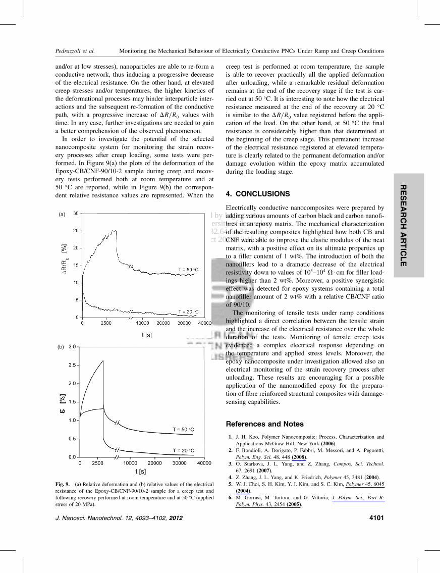
Delivered by Ingenta toHebrew University of Jerusalem
IP 132645431Mon 22 Oct 2012 171546
RESEARCH
ARTIC
LE
Pedrazzoli et al Monitoring the Mechanical Behaviour of Electrically Conductive PNCs Under Ramp and Creep Conditions
andor at low stresses) nanoparticles are able to re-form aconductive network thus inducing a progressive decreaseof the electrical resistance On the other hand at elevatedcreep stresses andor temperatures the higher kinetics ofthe deformational processes may hinder interparticle inter-actions and the subsequent re-formation of the conductivepath with a progressive increase of RR0 values withtime In any case further investigations are needed to gaina better comprehension of the observed phenomenonIn order to investigate the potential of the selected
nanocomposite system for monitoring the strain recov-ery processes after creep loading some tests were per-formed In Figure 9(a) the plots of the deformation of theEpoxy-CBCNF-9010-2 sample during creep and recov-ery tests performed both at room temperature and at50 C are reported while in Figure 9(b) the correspon-dent relative resistance values are represented When the
(a)
(b)
Fig 9 (a) Relative deformation and (b) relative values of the electricalresistance of the Epoxy-CBCNF-9010-2 sample for a creep test andfollowing recovery performed at room temperature and at 50 C (appliedstress of 20 MPa)
creep test is performed at room temperature the sampleis able to recover practically all the applied deformationafter unloading while a remarkable residual deformationremains at the end of the recovery stage if the test is car-ried out at 50 C It is interesting to note how the electricalresistance measured at the end of the recovery at 20 Cis similar to the RR0 value registered before the appli-cation of the load On the other hand at 50 C the finalresistance is considerably higher than that determined atthe beginning of the creep stage This permanent increaseof the electrical resistance registered at elevated tempera-ture is clearly related to the permanent deformation andordamage evolution within the epoxy matrix accumulatedduring the loading stage
4 CONCLUSIONS
Electrically conductive nanocomposites were prepared byadding various amounts of carbon black and carbon nanofi-bres in an epoxy matrix The mechanical characterizationof the resulting composites highlighted how both CB andCNF were able to improve the elastic modulus of the neatmatrix with a positive effect on its ultimate properties upto a filler content of 1 wt The introduction of both thenanofillers lead to a dramatic decrease of the electricalresistivity down to values of 103ndash104 middotcm for filler load-ings higher than 2 wt Moreover a positive synergisticeffect was detected for epoxy systems containing a totalnanofiller amount of 2 wt with a relative CBCNF ratioof 9010The monitoring of tensile tests under ramp conditions
highlighted a direct correlation between the tensile strainand the increase of the electrical resistance over the wholeduration of the tests Monitoring of tensile creep testsevidenced a complex electrical response depending onthe temperature and applied stress levels Moreover theepoxy nanocomposite under investigation allowed also anelectrical monitoring of the strain recovery process afterunloading These results are encouraging for a possibleapplication of the nanomodified epoxy for the prepara-tion of fibre reinforced structural composites with damage-sensing capabilities
References and Notes
1 J H Koo Polymer Nanocomposite Process Characterization andApplications McGraw-Hill New York (2006)
2 F Bondioli A Dorigato P Fabbri M Messori and A PegorettiPolym Eng Sci 48 448 (2008)
3 O Starkova J L Yang and Z Zhang Compos Sci Technol67 2691 (2007)
4 Z Zhang J L Yang and K Friedrich Polymer 45 3481 (2004)5 W J Choi S H Kim Y J Kim and S C Kim Polymer 45 6045
(2004)6 M Gorrasi M Tortora and G Vittoria J Polym Sci Part B
Polym Phys 43 2454 (2005)
J Nanosci Nanotechnol 12 4093ndash4102 2012 4101
Delivered by Ingenta toHebrew University of Jerusalem
IP 132645431Mon 22 Oct 2012 171546
RESEARCH
ARTIC
LE
Monitoring the Mechanical Behaviour of Electrically Conductive PNCs Under Ramp and Creep Conditions Pedrazzoli et al
7 C Zhao H Qin F Gong M Feng S Zhang and M Yang PolymDegrad Stab 87 183 (2005)
8 C F Ou and M C Hsu J Polym Res 14 373 (2007)9 A Pegoretti A Dorigato and A Penati Eur Polym J 44 1662
(2008)10 M Traina A Pegoretti and A Penati J Appl Polym Sci 106 2065
(2007)11 Z J Fan C Zheng T Wei Y C Zhang and G L Luo Polym
Eng Sci 49 2041 (2009)12 S Kumar L L Sun S Caceres B Li W Wood A Perugini R G
Maguire and W H Zhong Nanotechnology 21 105702 (2010)13 J H Lee Y K Jang C E Hong N H Kim P Li and H K Lee
J Power Sources 193 523 (2009)14 J Li P S Wong and J K Kim Materials Science and Engineer-
ing a-Structural Materials Properties Microstructure and Processing483ndash84 660 (2008)
15 P C Ma M Y Liu H Zhang S Q Wang R Wang K WangY K Wong B Z Tang S H Hong K W Paik and J K KimAcs Applied Materials amp Interfaces 1 1090 (2009)
16 J Sumfleth X C Adroher and K Schulte J Mater Sci 44 3241(2009)
17 M Tait A Pegoretti A Dorigato and K Kalaitzidou Carbon49 4280 (2011)
18 L Boumleger M H G Wichmann L O Meyer and K SchulteCompos Sci Technol 68 1886 (2008)
19 J C Abry S Bochard A Chateauminois M Salvia and G GiraudCompos Sci Technol 59 925 (1999)
20 J C Abry Y K Choi A Chateauminois B Dalloz G Giraud andM Salvia Compos Sci Technol 61 855 (2001)
21 P E Irving and C Thiagarajan Smart Materials amp Structures 7 456(1998)
22 A S Kaddour F A R Alsalehi S T S Alhassani and M JHinton Compos Sci Technol 51 377 (1994)
23 M Kupke K Schulte and R Schuler Compos Sci Technol 61 837(2001)
24 D C Seo and J J Lee Compos Struct 47 525 (1999)25 A Todoroki H Kobayashi and K Matuura Jsme International
Journal Series a-Mechanics and Material Engineering 38 524(1995)
26 A Todoroki K Omagari Y Shimamura and H KobayashiCompos Sci Technol 66 1539 (2006)
27 A Todoroki M Tanaka Y Shimamura and H KobayashiAdv Compos Mater 13 107 (2004)
28 A Todoroki and Y Tanaka Compos Sci Technol 62 629(2002)
29 N Muto Y Arai S G Shin H Matsubara H Yanagida M Sugitaand T Nakatsuji Compos Sci Technol 61 875 (2001)
30 E T Thostenson and T W Chou Advanced Materials 18 2837(2006)
31 A Dorigato S Morandi and A Pegoretti J Compos Mater(in press)
32 J Sumfleth S T Buschhorn and K Schulte J Mater Sci 46 659(2010)
33 A Dorigato M DrsquoAmato and A Pegoretti J Polym Res (in press)34 A Dorigato A Pegoretti F Bondioli and M Messori Composite
Interfaces 17 873 (2010)35 A Dorigato and A Pegoretti J Nanopart Res 13 2429 (2011)36 A Dorigato A Pegoretti and A Penati J Reinf Plast Compos
30 325 (2011)37 A Dorigato A Pegoretti and M Quaresimin Mater Sci Eng A
528 6324 (2011)38 A Dorigato and A Pegoretti Polym Int 59 719 (2010)39 A Dorigato L Fambri A Pegoretti M Slouf and J Kolarik
J Appl Polym Sci 119 3393 (2011)40 F Bondioli A Dorigato P Fabbri M Messori and A Pegoretti
J Appl Polym Sci 112 1045 (2009)41 Y Choi K Sugimoto S Song Y Gotoh Y Ohkoshi and M Endo
Carbon 43 2199 (2005)42 V Kostopoulos A Vavouliotis P Karapappas P Tsotra and
A Paipetis J Intell Mater Syst Struct 20 1025 (2009)43 C D Liu L F Cheng X G Luan B Li and J Zhou Mater Lett
62 3922 (2008)44 F Nanni G Ruscito D Puglia A Terenzi J M Kenny and
G Gusmano Compos Sci Technol 71 1 (2011)45 A Dorigato A Pegoretti and J Kolarik Polym Compos 31 1947
(2010)46 C Zhang P Wang C Ma G Wu and M Sumita Polymer 47 466
(2006)
Received 27 September 2011 Accepted 9 November 2011
4102 J Nanosci Nanotechnol 12 4093ndash4102 2012