monitoring the internet connections of wan ... - mikrotik · isp failover in mikrotik routers...
TRANSCRIPT
Asst. Prof. Dr. Ekarin Suethanuwong (MTCNA, MTCTCE, MikroTik Academy Trainer, MikroTik Certified Consultant)
Department of Information and Computer Management Faculty of Commerce and Management, Prince of Songkla University, Thailand
MUM Conference, August 14, 2018, Bangkok, Thailand
Monitoring the Internet Connections of WAN Links with Only Routing Configuration

PSU At a Glance... • 1st University in Southern Thailand, est. 1967
• 5 Campuses • 36,000 Students (2009)
Hat Yai
Trang Pattani
Phuket
Surat Thani
2

About Me Asst. Prof. Dr. Ekarin Suethanuwong
Lecturer at Prince of Songkla University (Trang Campus) MikroTik Certificates MTCNA and MTCTCE MikroTik Academy Trainer MikroTik Certified Consultant
Contact Me Email: [email protected] Facebook: www.facebook.com/ekarin.suethanuwong
3

What is ISP Failover? ISP Failover is an operation to automatically switch over to the standby ISP
when a primary ISP fails, i.e. it cannot provide its Internet service to the clients. Primary ISP (ISP1)
operates correctly
Primary ISP (ISP1)
fails its operation
4

ISP Failover in MikroTik Routers Failover to the standby ISP in MikroTik routers can be simply configured by
adding an default route with a higher value of the distance parameter in the routing table. This implies that the default route with a lower distance takes precedence over another one.
/ip route add gateway=“IP Address of ISP1 Gateway” check-gateway=ping distance=1
/ip route add gateway=“IP Address of ISP2 Gateway” check-gateway=ping distance=2
5

ISP Failover in MikroTik Routers Typically, monitoring the down state of an ISP is to periodically check the
operation of the ISP gateway, i.e. an ICMP request packet is transmitted to the IP addresses of the ISP gateway every period of time (10 seconds).
If the router does not get any ICMP response packet within the two timeouts (i.e. 20 seconds), it determines the ISP fails. It will then indicate the ISP gateway is unreachable and switch over the default route of another ISP gateway.
6

Typical Problems in ISP Failover The typical problem is that the router still get the ICMP responses from the
gateway of the primary ISP but the Internet cannot be accessible due to any possible problem behind the primary ISP.
In this way, all packets that are forwarded to the Internet are still transmitted to the gateway of the primary ISP.
The Internet cannot be accessible via ISP1 but the
gateway of ISP1 responses ICMP packets correctly 7

Typical Problems in ISP Failover The typical problem is that the router still get the ICMP responses from the
gateway of the primary ISP but the Internet cannot be accessible due to any possible problem behind the primary ISP.
In this way, all packets that are forwarded to the Internet are still transmitted to the gateway of the primary ISP.
8

Typical Problems in ISP Failover This is even worse in a case where some ASDL routers or ONU routers are not
allowed to configure to be in a bridge mode. The default root’s gateway is not the ISP gateway anymore.
9

Current Solution With Netwatch Currently the Netwatch tool is widely used in Thailand to monitor the Internet
connections of WAN links by checking a remote host instead of the nearby gateway. It works like the traditional way by periodically sending an ICMP request packet but
to a specified remote host in the Internet.
Host (8.8.8.8) via the ISP1 gateway Host (8.8.4.4) via the ISP2 gateway
10

Current Solution With Netwatch However scripting is needed to disable and enable default routes (by finding their
comments) in case where the up and down events of the remote hosts occur.
11

Current Solution With Netwatch However scripting in the Netwatch tool is needed to disable and enable default
routes (by finding their comments) in case where the up and down events of the remote host occur.
Each default root will be disabled and enabled by referring its comment parameter.
The Netwatch tasks will ping each remote hosts via a different route (or gateway).
12

Scripting in Netwatch It can be said that such scripting is not easy to accomplish for technicians who want
to implement network solutions with failover for their customers but they do not know much about scripting. They prefer to simply configure via WinBox with GUI.
Routes for remote hosts (i.e. 8.8.8.8 via the ISP1 gateway and 8.8.4.4 via the ISP2 gateway) must be added and always available for the Netwatch tool’s tasks.
13

Scripting in Netwatch The default root with the ISP1 comment is disabled when the Netwatch does not get
an ICMP response packet for a specified timeout (1 second) after sending an ICMP request packet via the ISP1 gateway (10.10.10.1).
14

Multiple Remote Hosts with Netwatch It is possible that a single remote host might be down, checking multiple remote
hosts per WAN link (such as Google DNS and OpenDNS) is required to confirm whether the Internet connection is really available per WAN link.
In this regard, using the Netwatch tool seems to be unable to cope with because it supports only a single remote host.
- Ping 8.8.8.8 and 204.67.220, 220 through ISP1
- Ping 8.8.4.4 and 204.67.222, 222 through ISP2
15

Solution with Only Routing Configuration An alternative solution that can figure out the previously mentioned problems is
done by configuring only routes in the routing table (/ip routes) without scripting and using the Netwatch tool at all.
This solution can be broken down into two scenarios: 1) Failover with checking a single remote host per WAN link 2) Failover with checking multiple remote hosts per WAN link
No Scripting & Netwatch
Only Routing Configuration
Being Able to Check Multiple
Remote Hosts per WAN Link
Reference [1] https://wiki.mikrotik.com/wiki/Manual:IP/Route [2] https://wiki.mikrotik.com/wiki/Advanced_Routing_Failover_without_Scripting 16
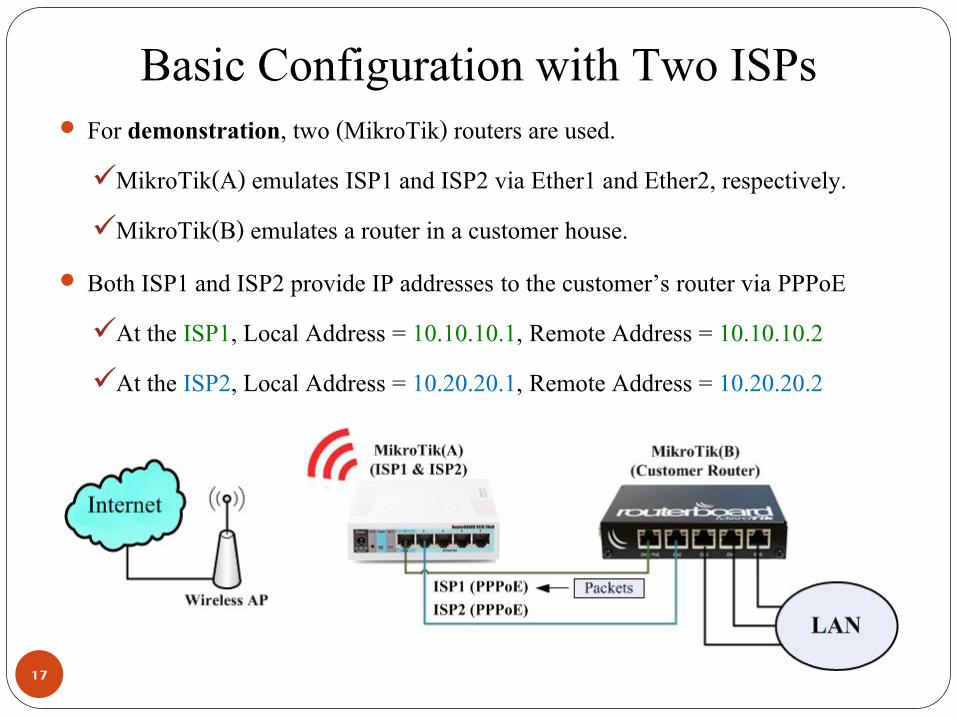
Basic Configuration with Two ISPs For demonstration, two (MikroTik) routers are used. MikroTik(A) emulates ISP1 and ISP2 via Ether1 and Ether2, respectively. MikroTik(B) emulates a router in a customer house.
Both ISP1 and ISP2 provide IP addresses to the customer’s router via PPPoE At the ISP1, Local Address = 10.10.10.1, Remote Address = 10.10.10.2 At the ISP2, Local Address = 10.20.20.1, Remote Address = 10.20.20.2
17
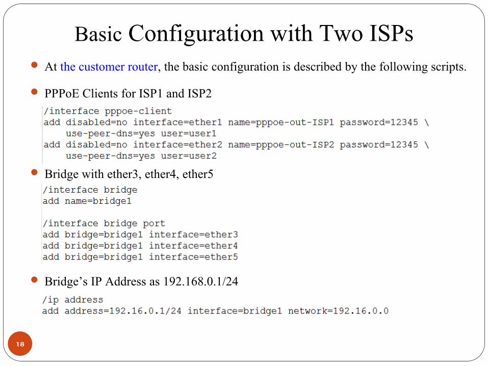
Basic Configuration with Two ISPs At the customer router, the basic configuration is described by the following scripts. PPPoE Clients for ISP1 and ISP2
Bridge with ether3, ether4, ether5
Bridge’s IP Address as 192.168.0.1/24
18

Basic Configuration with Two ISPs At the customer router, the basic configuration is described by the following scripts. DHCP Server with a pool of 192.168.0.2-192.168.0.254
DNS Server in the customer router
NAT for the PPPoE Clients of ISP1 and ISP2
19

Failover with Checking a Single Remote Host Failover with checking a single remote host per WAN link 1) Create default routes using remote hosts as gateways with different distances /ip route
add distance=1 gateway=8.8.8.8 check-gateway=ping add distance=2 gateway=8.8.4.4 check-gateway=ping
20

Failover with Checking a Single Remote Host Failover with checking a single remote host per WAN link 2) Create routes to the remote hosts using corresponding ISP gateways with scope=10
(the scope parameter must be less or equal to the target score parameter) /ip route
add dst-address=8.8.8.8 gateway=10.10.10.1 scope=10 add dst-address=8.8.4.4 gateway=10.20.20.1 scope=10
21

Failover with Checking Single Remote Hosts Testing: failover with checking a single remote host per WAN link Scenario#1: The ISP1 fails to access the Internet, the firewall rule in the
MikroTik(A) drops all packets from the ISP1 PPPoE to the Internet. The backup WAN link (to ISP2) should take over all packets to the Internet.
Customer Site
ISP Sites
22

Failover with Checking Single Remote Hosts Testing: failover with checking a single remote host per WAN link Scenario#2: The primary ISP1 has been recovered to be accessible to the Internet,
the firewall rule in the MikroTik(A) that drops all packets from the ISP1 is disabled. The WAN link (ISP1) should return to take over all packets to the Internet.
Customer Site
ISP Sites
23

Failover with Checking a Single Remote Host Failover with checking a single remote host per WAN link In case of load balancing, you have corresponding routing masks (toISP1, toISP2) The first step 1) is revised (adding default routes and changing distances) as follow. /ip route
add distance=1 gateway=8.8.8.8 routing-mask=toISP1 check-gateway=ping add distance=2 gateway=8.8.4.4 routing-mask=toISP1 check-gateway=ping
/ip route add distance=1 gateway=8.8.4.4 routing-mask=toISP2 check-gateway=ping add distance=2 gateway=8.8.8.8 routing-mask=toISP2 check-gateway=ping
24

Failover with Checking Multiple Remote Hosts Failover with checking multiple remote hosts per WAN link Google DNS (8.8.8.8, 8.8.4.4) and OpenDNS (208.67.220.220, 208.67.222.222) are
well known as trustable and stable DNS servers.
- Ping 8.8.8.8 and 204.67.220, 220 through ISP1
- Ping 8.8.4.4 and 204.67.222, 222 through ISP2
25
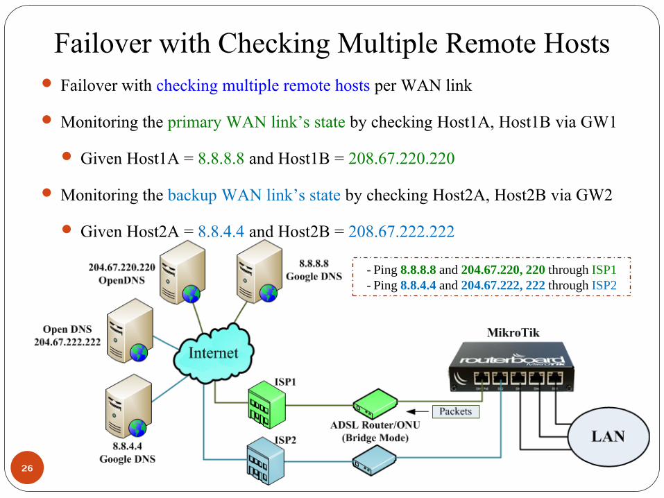
Failover with Checking Multiple Remote Hosts Failover with checking multiple remote hosts per WAN link Monitoring the primary WAN link’s state by checking Host1A, Host1B via GW1 Given Host1A = 8.8.8.8 and Host1B = 208.67.220.220
Monitoring the backup WAN link’s state by checking Host2A, Host2B via GW2 Given Host2A = 8.8.4.4 and Host2B = 208.67.222.222
- Ping 8.8.8.8 and 204.67.220, 220 through ISP1
- Ping 8.8.4.4 and 204.67.222, 222 through ISP2
26

Failover with Checking Multiple Remote Hosts Failover with checking multiple remote hosts per WAN link 1) Create default routes using remote hosts as gateways with different distances, but
instead of using remote hosts, two virtual hops (10.1.1.1 for GW1 and 10.2.2.2 for GW2) has been setup as corresponding gateways to simplify the default routes. /ip route
add distance=1 gateway=10.1.1.1 add distance=2 gateway=10.2.2.2
27

Failover with Checking Multiple Remote Hosts Failover with checking multiple remote hosts per WAN link 2) Create routes to the virtual hops using corresponding multiple remote hosts with
scope=10 /ip route
add dst-address=10.1.1.1 gateway=8.8.8.8 scope=10 check-gateway=ping add dst-address=10.1.1.1 gateway=208.67.220.220 scope=10 check-gateway=ping
/ip route add dst-address=10.2.2.2 gateway=8.8.4.4 scope=10 check-gateway=ping add dst-address=10.2.2.2 gateway=208.67.222.222 scope=10 check-gateway=ping
28

Failover with Checking Multiple Remote Hosts Failover with checking multiple remote hosts per WAN link 2) Create routes to the virtual hops using corresponding multiple remote hosts with
scope=10
1
29

Failover with Checking Multiple Remote Hosts Failover with checking multiple remote hosts per WAN link 3) Create routes to the remote hosts using corresponding ISP gateways with scope=10
(the scope parameter must be less or equal to the target score parameter) /ip route
add dst-address=8.8.8.8 gateway=10.10.10.1 scope=10 add dst-address=208.67.220.220 gateway=10.10.10.1 scope=10
/ip route add dst-address=8.8.4.4 gateway=10.20.20.1 scope=10 add dst-address=208.67.222.222 gateway=10.20.20.1 scope=10
30

Failover with Checking Multiple Remote Hosts Failover with checking multiple remote hosts per WAN link 3) Create routes to the remote hosts using corresponding ISP gateways with scope=10
(the scope parameter must be less or equal to the target score parameter)
31

Failover with Checking Multiple Remote Hosts Failover with checking multiple remote hosts per WAN link The result of manually adding such routes with the scope 10 can be checked in term
of next hop (/ip route nexthop print). Note that such routes are not connected routes. The gateway state “recursive” denotes that the gateway is used as the destination
address for the next round in finding the next appropriate route (with the scope 10) in the route list.
32

Failover with Checking Multiple Remote Hosts Testing: failover with checking multiple remote hosts per WAN link Scenario#1: The ISP1 fails to access the Internet, the firewall rule in the
MikroTik(A) drops all packets from the WAN link of ISP1 to the hosts (8.8.8.8 and 204.67.220.220).
The backup WAN link (to ISP2) should take over all packets to the Internet.
33

Failover with Checking Multiple Remote Hosts Testing: failover with checking multiple remote hosts per WAN link Scenario#1: The result in the route list shows that the default route through the ISP1
is unreachable, and the default route through the ISP2 has taken over.
34

Failover with Checking Multiple Remote Hosts Testing: failover with checking multiple remote hosts per WAN link Scenario#2: The ISP1 must be able to access the Internet, even if the host (8.8.8.8)
fails. The firewall rule in the MikroTik(A) drops all packets from the WAN link of ISP1 to only the hosts (8.8.8.8).
The primary WAN link (to ISP1) should still take over all packets to the Internet.
35

Failover with Checking Multiple Remote Hosts Testing: failover with checking multiple remote hosts per WAN link Scenario#2: The result in the route list shows that the default route through the ISP1
is reachable via the ISP1 gateway (10.10.10.1).
36
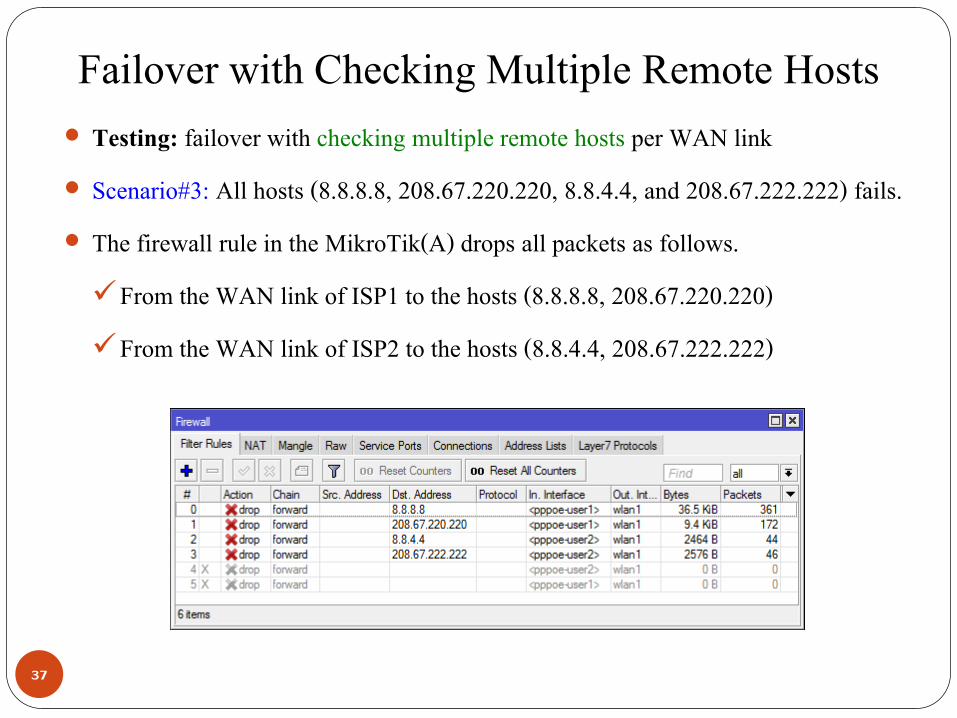
Failover with Checking Multiple Remote Hosts Testing: failover with checking multiple remote hosts per WAN link Scenario#3: All hosts (8.8.8.8, 208.67.220.220, 8.8.4.4, and 208.67.222.222) fails. The firewall rule in the MikroTik(A) drops all packets as follows. From the WAN link of ISP1 to the hosts (8.8.8.8, 208.67.220.220) From the WAN link of ISP2 to the hosts (8.8.4.4, 208.67.222.222)
37

Failover with Checking Multiple Remote Hosts Testing: failover with checking multiple remote hosts per WAN link Scenario#3: The result in the route list shows that the default route through both
ISP1 and ISP2 are unreachable.
38

Failover with Checking Multiple Remote Hosts Testing: failover with checking multiple remote hosts per WAN link Scenario#4: All hosts (8.8.8.8, 208.67.220.220, and 8.8.4.4) fails but only the host
(208.67.222.222) is fine. The firewall rule in the MikroTik(A) drops all packets as follows. From the WAN link of ISP1 to the hosts (8.8.8.8, 208.67.220.220) From the WAN link of ISP2 to the hosts (8.8.4.4)
39
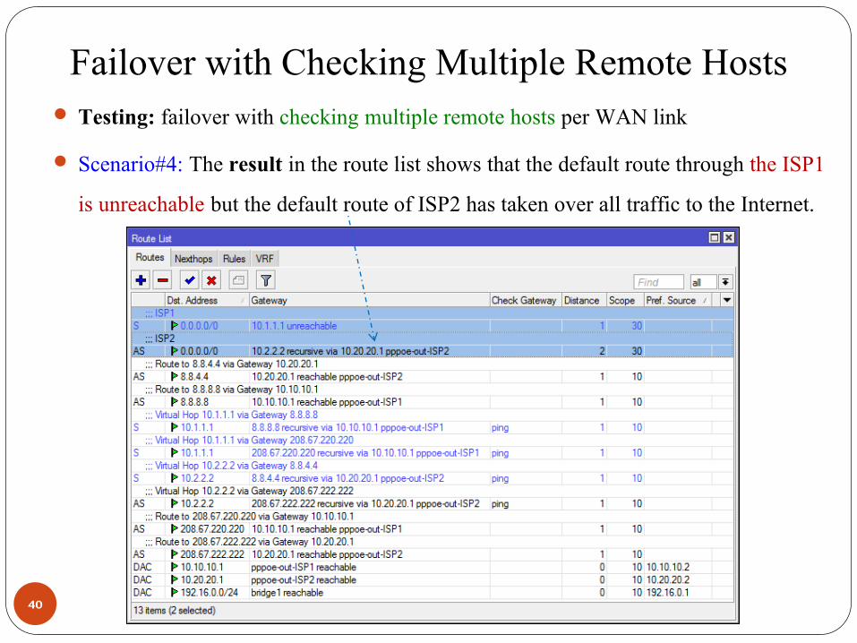
Failover with Checking Multiple Remote Hosts Testing: failover with checking multiple remote hosts per WAN link Scenario#4: The result in the route list shows that the default route through the ISP1
is unreachable but the default route of ISP2 has taken over all traffic to the Internet.
40

Failover with Checking Multiple Remote Hosts Failover with checking multiple remote hosts per WAN link In case of load balancing, you have corresponding routing masks (toISP1, toISP2) The first step 1) is revised (adding default routes and changing distances) as follow /ip route
add distance=1 gateway=10.1.1.1 routing-mask=toISP1 add distance=2 gateway=10.2.2.2 routing-mask=toISP1
/ip route add distance=1 gateway=10.2.2.2 routing-mask=toISP2 add distance=2 gateway=10.1.1.1 routing-mask=toISP2
41

Reference [1] https://wiki.mikrotik.com/wiki/Manual:IP/Route [2] https://wiki.mikrotik.com/wiki/Advanced_Routing_Failover_without_Scripting
42