monitoring and evaluation (m&e) manual on...
TRANSCRIPT

PART-II
MONITORING AND EVALUATION (M&E) MANUAL ON CONSTRUCTION WORKS
(Roads, Bridges and Culverts)
Prepared by: Nisar Ahmad Khan
Monitoring and Evaluation Consultant, SMECI Project
November, 2015
Table of Contents
SL. No. Contents Page No.
Acknowledgement i
Executive Summary ii-iii
Abbreviation and acronyms iv-v
1. Background 1-2
2. Why is monitoring and evaluation important 2-3
3. Monitoring and Evaluation practice in Bangladesh 3-4
4. Emphasis on field/ site inspection 4
5. Site inspection of Civil Works (RHD) related projects 5-6
5.1 Attitude/approach of the inspector 6-7
6. M&E manual for civil works 7
7. Preparation for project Inspection by using M& E Manual 7-8
8. Inspection of Roads, Bridges and Culverts 8
9. Steps in construction of road 9-28
10. Stages of Bridge Construction 29
10.1 Essential tests and equipment required to ensure quality 29-30
10.2 Bridge construction Stages 31-38
11. Stages of Culvert’s Construction 39
12. Study of Project Document 40
13. Study of procurement discipline 40
14. Study of roads related technical discipline 40
15. Study of Project implementation arrangements 40-41
16. Checking quality of works 41
16.A Establishing site office and on-site testing facilities 41-42
16.B Maintenance of site inspection register/book 42
16.C Use of visual aid during inspection 42
17. Removal of temporary structures and backfilling 43
18. Conclusion: 43
Annex-1-Checklist for DPP 44-46
Annex-2-Checklist for TPP 47-48
Annex-3-Checklist for procurement of construction works (RHD) 49-52
Annex-4-Checklists for roads, bridges and culverts construction 53-57
Annex-5- Checklist for quality check of Bituminous Pavement 58

ACKNOWLEDGEMENTS
I like to convey my heartfelt thanks and sincere gratitude to a number of people who
help me in completing this guidebook/manual. First, words cannot convey my gratitude
to Md. Shahid Ullah Khandaker, Secretary, IMED, Ministry of Planning and Md.
Habibul Islam, Project Director, SMECI Project, IMED whose untiring patience and
attention to detail enabled me to complete this manual and get it into its present form.
Despite their busy schedule they gave unstintingly of their time. Apart from the
administrative side, the honour and care I received from them were invaluable, which
I deeply acknowledge. I would extend my thanks and gratitude to the other officials of
IMED and SMECI Project as well for allowing me to formulate this document time to
time. Needless to say, without the cooperation of my fellow colleague Mr. Javed, Mr.
Raihan, Mr. Rahman, Mr. sanjoy and Shahina Sultana the study would have been
impossible. I feel honored to express my deep sense of gratitude to all the
stakeholders for their cordial response and cooperation. I also thank them most
sincerely for the hours they spent talking to us and the hospitality they offered. I am
extremely grateful to Md. Sefaul Alam, Director General (Addl. Secretary),
Communication Sector of IMED and his officers Engr. Momit and Engr. Ashraf for
going through the documents and help in improving the technical aspect of the manual.
Last but not the least, I am thankful to all the authors from home and abroad whose
publications have helped me to design my manual more scientifically and with strong
foundation. All limitations within this document are absolutely mine and I am solely
responsible for errors and omissions in this manual.
EXECUTIVE SUMMARY
The role of IMED was limited to only monitoring of projects till 1982 when project
evaluation responsibility was added to its portfolio. IMED made a humble effort in this
direction by initially evaluating few completed projects. Within a short period, it started
evaluating all the completed projects during a particular fiscal year. Of late, it has
started outsourcing consultants every year to carry out evaluation of few important
completed projects/programs and this policy is continuing till date.
Encadrement of IMED’s posts in 1982 in the BCS Economic Cadre is considered as a
milestone, when its door was opened up with an objective to bring more agility and
dynamism in its function through continuous induction of new blood in the system.
IMED’s job being a bit different than the job of the other Ministries and Divisions, it
demands a bit different training and attitude to accomplish it professionally. Monitoring
and Evaluation being two very important functions of IMED, each one of it requires
special attention and treatment.
So long, on the basis of ‘learning by doing’, newly posted or recruited officers have
been carrying out their responsibilities of monitoring and evaluation. Of course, a small
05 page inspection guideline followed by a 06 page format of Project Inspection Report
was prepared in 1995 and was practiced till 2004 when Project Inspection Report
format was revised and reduced to a 02 page format and was named as IMED
06/2003. Both these guidelines contain number of instructions to the intending field
inspecting officials. These instructions cover almost all aspects of project activities. It
directs only what to be inspected, and not how to be inspected and check quality of
construction work. Therefore, necessity of a comprehensive manual/guideline on
monitoring & evaluation is felt by everybody including the newcomers in the IMED. To
facilitate and enhance skill of the officers and to strengthen the capability of the
organization, Monitoring & Evaluation Manual for Civil Works (Buildings, Roads,
Bridges and Culverts) is prepared. The manual consists of two parts. Part-I relates to
‘Building’ construction whereas Part-II deals with construction of ‘Roads, Bridges and
Culverts’.
ii
The manual is based on less theoretical deliberations and more practical oriented
questions in the form of checklists on various aspects of project implementation. The
checklists are supposed to lessen the burden of inspecting officials of going through
various documents like DPP/TPP, procurement etc. this will help save valuable time
and concentrate more on collecting useful data/information from the field.
There are as many as 28 Checklists (Part-I contains 23 nos. and Part- II contains 5
nos.) in this manual. Some are quite elaborate and some are short. These checklists
are basically divided into 2 categories. One category relates to the DPP/TPP and
Public Procurement Rules and Acts and the others belong to quality checks for civil
construction work in the field. As many of the checklists of Part-I cover the construction
areas of the Part-II, these are not annexed with Part-II of the manual.
The checklists in the form of questionnaires are given for the purpose of strengthening
an inquisitiveness related to the technical subject and also develop confidence in
oneself. The questionnaires will help know and learn the technicalities involved in
checking the quality and workmanship in the construction works.
Delay in procurement of goods, works and services is nationally identified as a major
cause in project execution. To overcome the situation, government, with the
assistance of the World Bank has initiated many steps through CPTU of IMED. One
of them being, developing PPA-2006 and PPR-2008. Recently CPTU has developed
45 key indicators for monitoring procurement contracts of few selected organizations
for monitoring their procurement performances.
However, the Consultant has developed a comprehensive checklists for procurement
of construction works appended as Annexure-3 in the manual, where 45 key
indicators mentioned in the above paragraph have also been taken care of. This
Annexure will help IMED officials to analyse various contracts thoroughly, pin point
specific steps where inordinate delays have occurred and suggest measures to
contain them effectively.
Checklists of the manual are quite exhaustive and have covered almost all areas of
construction that an IMED official would be interested to look into.
iii

ABBREVIATION AND ACRONYMS
AA Approving Authority
ACV Aggregate Crushing Value
BCR Benefit Cost Ratio
BCS Bangladesh Civil Service
C.C. Cement Concrete
C.B.R. Test California Bearing Ratio Test
CONTASA Convertible Taka Special Account
CPTU Central Procurement Technical Unit
DOSA Dollar Special Account
DP Development Partner
DoFP Delegation of Financial Power
DPP Development Project Proforma
ECNEC Executive Committee for National Economic Council
EOI Expression of Interest
FDD Field Dry Density
GCC General Conditions of Contract
HOPE Head of Procuring Entity
HRD Human Resource Development
IFB Invitation for BID
IFT Invitation for Tender
IMED Implementation Monitoring and Evaluation Division
IRR Internal Rate of Return
LD Liquidated Damage
LOI Letter of Intent
LTM Letter Tender Method
MDD Maximum Dry Density
MDG Millennium Development Goal
M&E Monitoring and Evaluation
NA Not Applicable
NOA Number of Application
iv

NPV Net Present Value
NEC National Economic Council
OMC Optimum Moisture Content
OTM Open Tender Method
PCC Particular Conditions of Contract
PC Girder Pre-stressed Concrete Girder
PE Procuring Entity / Project Engineer
PEC Project Evaluation Committee
PIB Project Implementation Bureau
PO Purchase Order
PPA Public Procurement Act
PPR Public Procurement Rules
PIC Project Implementation Committee
PRS Poverty Reduction Strategy
PWD Public Works Department
RHD Roads and Highways Department
R.C.C. Reinforcement Cement concrete
REOI Request for Expression of Interest
RPA Reimbursable Project Aid
RFP Request for Proposal
PSC Project Steering Committee
SAFE Special Account for Foreign Exchange
SMECI Strengthening Monitoring and Evaluation Capabilities of IMED
STD Standard Tender Document
SPD Standard Prequalification Document
SRFQ Standard Request for Quotation
TFV Ten Percent Fine Value
TEC Tender Evaluation Committee
TOC Tender Opening Committee
TPP Technical Project Proforma
TEC Technical Evaluation Committee
v
Final Draft Manual on Roads, Bridges and Culverts
1
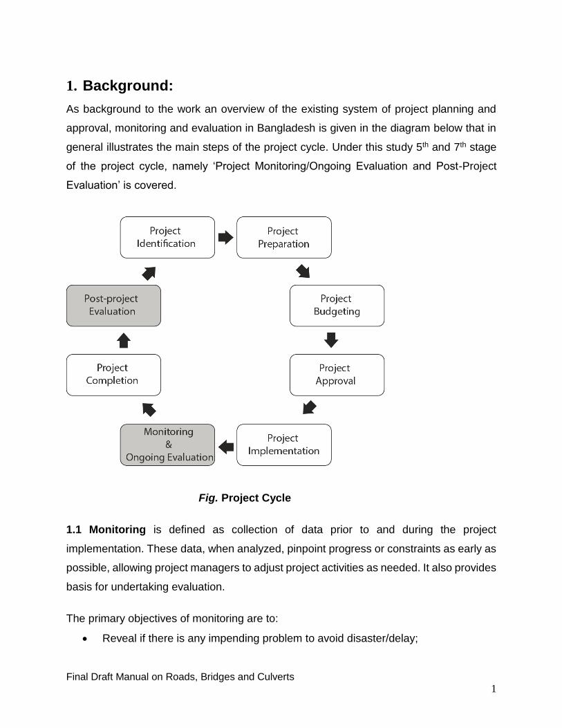
1. Background:
As background to the work an overview of the existing system of project planning and
approval, monitoring and evaluation in Bangladesh is given in the diagram below that in
general illustrates the main steps of the project cycle. Under this study 5th and 7th stage
of the project cycle, namely ‘Project Monitoring/Ongoing Evaluation and Post-Project
Evaluation’ is covered.
Fig. Project Cycle
1.1 Monitoring is defined as collection of data prior to and during the project
implementation. These data, when analyzed, pinpoint progress or constraints as early as
possible, allowing project managers to adjust project activities as needed. It also provides
basis for undertaking evaluation.
The primary objectives of monitoring are to:
Reveal if there is any impending problem to avoid disaster/delay;

Final Draft Manual on Roads, Bridges and Culverts
2
Assess the progress of the project with respect to the proposed timeline;
Make necessary adjustments in resources, if necessary;
Ensure quality of the ongoing work;
Learn weakness and strength of the project management.
Redesign or readjust project implementation strategies or project components to
achieve desired objective.
1.2 Evaluation is defined as a structured process of assessing the success of a project
in meeting its goal and to reflect on the lessons learned. It is carried out mostly at the end
of a project work. Evaluation is not just about demonstrating success, it is also about
learning why things went wrong. As such, identifying and learning from mistakes is one
of the key aspects of evaluation.
The primary objectives of evaluation are to:
Understand how the project has achieved its intended purpose, or why it may not
have done so;
Identify how efficient the project was in converting resources into activities,
objectives and goals;
Assess how sustainable and meaningful the project was;
Inform decision-makers on how to build on or improve future projects.
The key difference between monitoring and evaluation is that evaluation is about placing
a value judgment on the information gathered during a project, including the monitoring
data. The assessment of a project’s success (its evaluation) can be different based on
whose value judgment is used. For example, a project manager’s evaluation may be
different to that of the project’s participants, or other stakeholders.
2. Why is monitoring and evaluation important?
Monitoring and evaluation are critical tools for identifying and documenting successful
projects and approaches and tracking their progress. This is especially more relevant and
essential in resource poor countries like Bangladesh, where difficult decisions need to be
made with respect to resource allocation priorities.

Final Draft Manual on Roads, Bridges and Culverts
3
At the program level, the purpose of monitoring and evaluation is to track implementation
and outputs systematically. Monitoring and evaluation forms the basis for modification
and interventions and assessing the quality of work done.
Monitoring and evaluation can be used to demonstrate whether project has achieved the
expected outcomes or not. It is essential in helping managers, planners, implementers,
policy makers and funding agencies acquire the information and generate informed
decisions about project implementation.
Monitoring and evaluation helps identify the most efficient use of resources and provide
the necessary information to guide strategic planning, design and implementation of
projects, and to allocate, and re-allocate resources in better ways.
3. Monitoring and Evaluation practice in Bangladesh:
Project Implementation Bureau (PIB) was created in 1975 through an executive order as
a central project monitoring organization of the Government of Bangladesh. The PIB latter
upgraded, renamed Implementation Monitoring and Evaluation Division (IMED) and was
reorganized in 1982 to perform its function in a better way.
In 1986, Terminal Evaluation of completed projects was started by the IMED. Impact
Evaluation activity was initiated with the attachment of Population Development and
Evaluation Unit (PDEU) (Before it was placed under IMED, it was functioning as a project
in the Planning Commission to carry out evaluation study of Health Sector programs) to
the IMED in 1992.
Initially, project monitoring activities were mostly limited to financial performance reporting
of projects. Although, physical progress reporting formats were also in place, IMED’s data
analysis activities and reports were limited mostly to observations. The reports based on
those observations were prepared from (project) reports received from the
ministries/agencies.
According to The Rules of Business of the government allocated the following functions
or activities to the IMED:
Monitoring and Evaluation of the implementation of development projects included
in the Annual Development Program.

Final Draft Manual on Roads, Bridges and Culverts
4
Collection and compilation of project-wise data for preparing quarterly, annual and
periodical progress reports for information of the President, NEC, ECNEC,
Ministries and other concerned.
Rendering such advisory or consultancy services to Ministries/Agencies
concerned on implementation of projects as and when necessary.
Field inspection of projects for on the spot verification of implementation status
and such other Co-ordination works as may be necessary for the removal of
implementation problems, if any, with the assistance of related
Ministries/Agencies.
Submission of project inspection reports to the President and Ministers concerned
when attention at such levels are considered necessary.
Matters relating to Central Procurement Technical Unit (CPTU).
Matters relating to The Public Procurement Rules (PPR), 2008.
Such other functions as may be assigned to the Division by the Prime Minister from
time to time.
4. Emphasis on field/ site inspection:
Field inspection is one of the important tools of monitoring and evaluation, and that is
being carried out by the IMED in Bangladesh with the available resources. Field
inspection of the projects is one of the duties and responsibilities of the IMED enshrined
in its Rules of Business. And it is being religiously executed by the organization from its
very beginning to fulfil its obligation.
Emphasis given on the field inspection by the IMED can be understood by the fact that
every officer of the organization is required to visit at least 3 projects every month and
submit its inspection reports to the government for necessary action. This practice was
made mandatory for every officer, including the DGs through an internal order and that is
being followed by the organization for about 25 years.
IMED also involves itself in investigative inspection reporting, whenever and wherever it
is necessary or it is desired by the higher authority to do so for the benefit of the project
implementation.

Final Draft Manual on Roads, Bridges and Culverts
5
5. Site inspection of Civil Works (RHD) related projects:
Field inspection gives an on the spot impression of project performance in its
implementation phase. Since most of the investment projects have civil construction/
physical work component, the overall physical progress of work of any project can only
be assessed properly through site visits. Site visits gives an opportunity to see whether
the works are being carried out as per the approved plan document or there are deviations
from the approved DPP. Besides, the rate of progress of work vis-a-vis the utilization of
funds can also be assessed as to whether there are possibility of time and cost overruns.
Through project inspection early forecast of the likely problems/hazards in the
implementation phase can be made in advance and the remedial/corrective measures
can be suggested.
Inspection and quality assurance of project implementation is the ultimate responsibility
of the respective Ministry/Agency, though it is contractor’s responsibility to guarantee
quality of works as per terms of the contract. However, in order to have an
impartial/unbiased view of the project performance inspection by the independent and
higher body like IMED becomes pertinent. Field inspection gives an opportunity to see
whether the works are being carried out as per the approved plan and design
standards/specifications or there are deviations from the approved DPP. Besides the rate
of progress of work vis-a-vis the utilization of funds can also be assessed as to whether
there are possibility of time and cost overruns. These findings and recommendations form
the core of the report.
There was a time when all the construction materials (like bricks cement, MS rod, sanitary
fittings etc.) used to be supplied by the Roads and Highways Department (RHD) and the
contractor has to take delivery of the materials from the store, carry it to specific site/s
and complete the job in time. This practice was inherited from pre-independence days.
But in late seventies, the flaw in the whole system was detected by an investigating teams
constituted by the government. It was revealed that different construction materials and
construction related equipment worth millions of Taka were lying in different RHD stores
scattered all over Bangladesh. Some of the equipment and materials were even

Final Draft Manual on Roads, Bridges and Culverts
6
continuing in the inventory of the store from Pakistan days. In some cases these materials
and equipment were purchased to block funds allocated to the departments each Fiscal
Year. This led to corruption and misuse of fund as well.
However, this position changed dramatically after revelation and government decided to
put the responsibility of supplying the needed construction materials and equipment, for
constructing roads and other civil works etc., on the shoulder of the contractor, leaving
only the supervisory role to be played by the indenting agency. In short, the agency
required to look intensely to ensure quality of material supplied by the contractor and
supervise the construction work to ensure quality of work done by him (the contractor) as
per specifications of the contract and also determine its completion within the specified
time frame.
5.1 Attitude/approach of the inspector:
The inspecting officer may or may not be an engineer but the person sitting in front of
him/her (Project Director) probably is; who is also likely to be senior in age and is
supposed to know his job well. Therefore, approach of the visiting official has to be nice,
positive and friendly with him. The visitor should not hurt him by his behavior. Because
an inspector needs his/her office’s 100% cooperation for collecting project information
from the field. His/her non-cooperation may lead to unproductive visit, resulting in
wastage of time, money and energy. Achievement of project’s target is attributed to a
team efforts and not to an individual, therefore a Project Director (PD) alone should not
be put in the dock for failure to achieve the target of project. A Project Director does not
live in isolation. He does not have absolute control on the entire risk and assumptions of
the project activities.
An inspector should encourage PD to speak freely about the impediments project is
encountering in its implementation. Negative attitude of an inspector towards PD may
discourage PD to divulge any information that may, in his perception, harm him or his
superior in hierarchy. In short, the atmosphere of collecting information from the field
should be kept lively and cool to the extent it is possible from inspecting official’s side.
As this manual/guideline deals with the highly technical engineering subjects, it would be
advisable to IMED officials in general, whether engineer or non-engineer, to avoid

Final Draft Manual on Roads, Bridges and Culverts
7
entering into debate or arguments on the matter of ‘design’, whether it is a building design
or bridge design or any other structural design. It is a specialized area and the matter
should always be left to those who have specialization in the subject. Debate or
arguments on the subject may not be helpful rather it can prove to be counterproductive.
6. M & E manual for civil works:
This M&E manual is a reference document which provides— step-by-step guidance on
how to perform a specific task. It contains many sets of instructions containing DOs and
DON’Ts. This M&E manual includes specific steps/ instructions to be followed by the
inspecting/investigating officials of the IMED.
The purpose of the manual is as follows:
To provide an operational framework for achieving the IMED’s M&E goals.
To explain its working procedures
To provide clear inspection/investigation guidance for the IMED’s officials
To establish standard internal reporting system
To improve quality of project monitoring and evaluation
To ensure consistency in M&E within the sectors/sub-sectors
To enhance inspection skill of the IMED’s official
To improve quality of reporting.
This manual will require periodic updating for keeping pace with the development strategy
of the government as well as the monitoring and evaluation policy of the IMED.
7. Preparation for project inspection by using M& E Manual:
Before embarking on project inspection a number of preparatory works are necessary to
be taken to make it more effective and meaningful. In brief, these steps are:
Having knowledge about the stages of construction of a roads, bridges and
culverts will be helpful in understanding the project activities and it’s efficient
management.

Final Draft Manual on Roads, Bridges and Culverts
8
Holding a pre-inspection meeting with the Project Director/Project Management,
preferably in the IMED, to get an overall impression of the project progress and the
impediments centering round the project implementation.
Preparing inspection schedule in consultation with the project officials, so that
inspection is completed within a reasonable time period.
Studying yearly, quarterly and monthly reports (by using IMED’s 01/2003, 02/2003,
03/2003 , 04/2003 and 05/2003 formats or newly developed two formats, 2015) of
the project received in the IMED and filling in part of the inspection report with
static data/information before going to the field or by using online PMIS.
Studying Development Project Proforma (DPP)
Studying procurement plan provided in the DPP in the light of PPA-2006 and PPR-
2008
8. Inspection of Roads, Bridges and Culverts:
Road is constructed on the earthen embankment. Earth is compacted in layers and raised
to a specified height. On the top of the embankment pavement is constructed for
movement of the traffic. The lower part of the pavement is called sub-grade. On this sub-
grade two or more layers of base Course are constructed as per requirement of the
design. Surface Course is done on this Base Course. On both sides of the pavement
naked surface used by the pedestrians or light transports is called shoulder. As per design
requirement every embankment has slopes on its both sides. At the end of the slope earth
is specially treated to ensure durability of the embankment. This portion is known as
’Berm’. From the middle of the road, pavement has slopes on both sides. This slope is
known as ‘Camber’ or ‘Cross fall’. Camber is maintained as per design requirement, and
it helps drain out rain water quickly and protect the road from getting damaged.
This is being a purely technical subject, it requires a monitor to have some acquaintance
with technical terminologies of civil construction work and some basic knowledge of the
subject. This manual is prepared with that purpose. It tries to provide a monitor with
knowledge and knowhow of construction of different stages of Roads, Bridges and
Culverts.

Final Draft Manual on Roads, Bridges and Culverts
9
9. Steps in construction of road:
9A. Road construction equipment:
Before introducing to road construction activities it is desirable to get acquainted with the
equipment that are usually used in road construction:
Sl. Name of the equipment Images of the equipment
1. Excavator:
Excavators are heavy construction
equipment consisting of a boom, stick, bucket and
cab on a rotating platform known as the
"house". The house sits atop an undercarriage
with tracks or wheels. A cable-operated excavator
uses winches and steel ropes to accomplish the
movements. They are a natural progression from
the steam shovels and often called power shovels.
Excavators are also called Diggers. It is used for
various purposes, like:
Digging of trenches, holes, foundations Road construction work Material handling Forestry work Demolition General grading/landscaping Mining, especially, but not only open-pit
mining River dredging Driving piles, in conjunction with a pile
driver etc.
Fig: Excavator

Final Draft Manual on Roads, Bridges and Culverts
10
Sl. Name of the equipment Images of the equipment
2.
Pay loader:
A loader (bucket loader, front loader, front-end
loader, pay loader, scoop, shovel, skip loader,
or wheel loader) is a heavy equipment machine
used in construction and sidewalk maintenance to
move aside or load materials such as asphalt,
demolition debris, dirt, snow, feed, gravel, logs,
raw minerals, recycled material, rock, sand,
woodchips, etc. into or onto another type of
machinery (such as a dump truck, conveyor belt,
feed-hopper, or railroad car).
Fig: Pay Loader
Final Draft Manual on Roads, Bridges and Culverts
11
Sl. Name of the equipment Images of the equipment
3.
4.
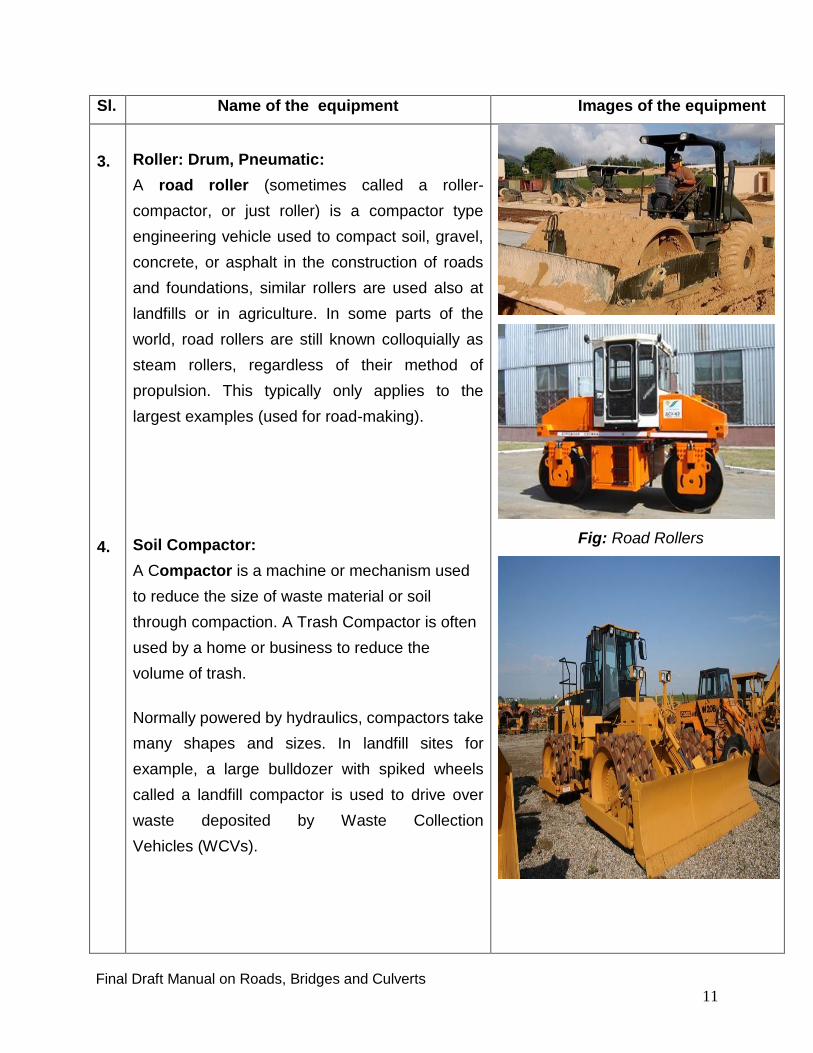
Roller: Drum, Pneumatic:
A road roller (sometimes called a roller-
compactor, or just roller) is a compactor type
engineering vehicle used to compact soil, gravel,
concrete, or asphalt in the construction of roads
and foundations, similar rollers are used also at
landfills or in agriculture. In some parts of the
world, road rollers are still known colloquially as
steam rollers, regardless of their method of
propulsion. This typically only applies to the
largest examples (used for road-making).
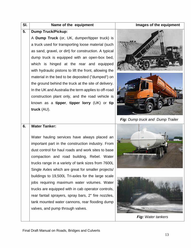
Soil Compactor:
A Compactor is a machine or mechanism used
to reduce the size of waste material or soil
through compaction. A Trash Compactor is often
used by a home or business to reduce the
volume of trash.
Normally powered by hydraulics, compactors take
many shapes and sizes. In landfill sites for
example, a large bulldozer with spiked wheels
called a landfill compactor is used to drive over
waste deposited by Waste Collection
Vehicles (WCVs).
Fig: Road Rollers

Final Draft Manual on Roads, Bridges and Culverts
12
Sl. Name of the equipment Images of the equipment
WCVs themselves incorporate a compacting
mechanism which is used to increase
the payload of the vehicle and reduce the number
of times it has to empty. This usually takes the
form of hydraulically powered sliding plates which
sweep out the collection hopper and compress the
material into what has already been loaded.
Different compactors are used in scrap
metal processing, the most familiar being the car
crusher. Such devices can be of either the
"pancake" type, where a scrap automobiles
flattened by a huge descending hydraulically
powered plate, or the baling press, where the
automobile is compressed from several directions
until it resembles a large cube.
Fig: Soil compactors
Final Draft Manual on Roads, Bridges and Culverts
13
Sl. Name of the equipment Images of the equipment
5. Dump Truck/Pickup:
A Dump Truck (or, UK, dumper/tipper truck) is
a truck used for transporting loose material (such
as sand, gravel, or dirt) for construction. A typical
dump truck is equipped with an open-box bed,
which is hinged at the rear and equipped
with hydraulic pistons to lift the front, allowing the
material in the bed to be deposited ("dumped") on
the ground behind the truck at the site of delivery.
In the UK and Australia the term applies to off-road
construction plant only, and the road vehicle is
known as a tipper, tipper lorry (UK) or tip
truck (AU).
Fig: Dump truck and Dump Trailer
6. Water Tanker:
Water hauling services have always placed an
important part in the construction industry. From
dust control for haul roads and work sites to base
compaction and road building, Rebel. Water
trucks range in a variety of tank sizes from 7600L
Single Axles which are great for smaller projects/
buildings to 19,500L Tri-axles for the large scale
jobs requiring maximum water volumes. Water
trucks are equipped with in cab operator controls,
rear fantail sprayers, spray bars, 2" fire nozzles,
tank mounted water cannons, rear flooding dump
valves, and pump through valves.
Fig: Water tankers

Final Draft Manual on Roads, Bridges and Culverts
14
Sl. Name of the equipment Images of the equipment
Water trucks are GPS equipped and dispatched.
This allows for effective fleet management with
quicker response times, assists in accurate billing
and provides up to the minute information to our
customers.
7. Asphalt plant:
An Asphalt Plant is a plant used for the
manufacture of asphalt, macadam and other
forms of coated road stone, sometimes
collectively known as blacktop or asphalt
concrete.
The manufacture of coated road stone demands
the combination of a number
of aggregates, sand and a filler (such as stone
dust), in the correct proportions, heated, and
finally coated with a binder, usually bitumen based
or, in some cases, tar. The temperature of the
finished product must be sufficient to be workable
after transport to the final destination. A
temperature in the range of 100 - 200 degrees
Celsius is normal.
Increasingly, recycled asphalt pavement (RAP) is
used as part of the mix. The binder used is
flammable, and the heaters are large liquid or gas
fired burners. RAP is introduced after the heating
process and must be accounted for in the overall
mix temperature calculations.

Final Draft Manual on Roads, Bridges and Culverts
15
Sl. Name of the equipment Images of the equipment
There are three main classes of plant: batch
heater, semi-continuous (or "asphalt plant"), and
continuous (or "drum mix"). The batch heater has
the lowest throughput, the continuous plant the
highest at up to around 500 Tones per hour.
Supply of road stone for large contracts is
generally by tender with considerable pressure on
price. A faulty batch of road stone must be planed
up and re-laid, often with additional lane
rental charges, at a cost which may be orders of
magnitude higher than the original price, so
sophisticated control systems are a necessity.
Fig: Asphalt plants for road construction
8. Bitumen Sprayer:
A Bitumen Spray seal is usually a two-coat
system. Liquid bitumen is sprayed onto a
prepared road base surface via a computerized
application. A 14mm aggregate is spread in a
uniform layer and rolled with a rubber tyred
roller. A second coat of bitumen is sprayed,
followed by a layer of 7mm aggregate (which fills
the voids between the aggregate of the previous
coat) and then rolled.
The surface texture of a spray seal is coarse with
an amount of excess (or loose) stone on the
surface. This is usually left and will bed in over
time. Bitumen spray seals are suitable for country
areas or longer driveways, marshalling yards, etc.
Fig: Bitumen Sprayer
Final Draft Manual on Roads, Bridges and Culverts
16
9B. Steps in construction of road segments:
Sl. Activities Images of activities
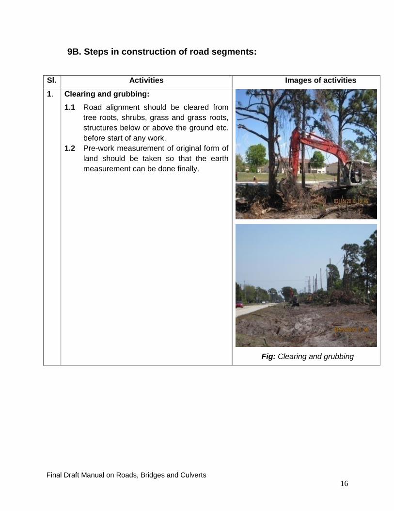
1. Clearing and grubbing:
1.1 Road alignment should be cleared from
tree roots, shrubs, grass and grass roots,
structures below or above the ground etc.
before start of any work.
1.2 Pre-work measurement of original form of
land should be taken so that the earth
measurement can be done finally.
Fig: Clearing and grubbing
Final Draft Manual on Roads, Bridges and Culverts
17
Sl. Activities Images
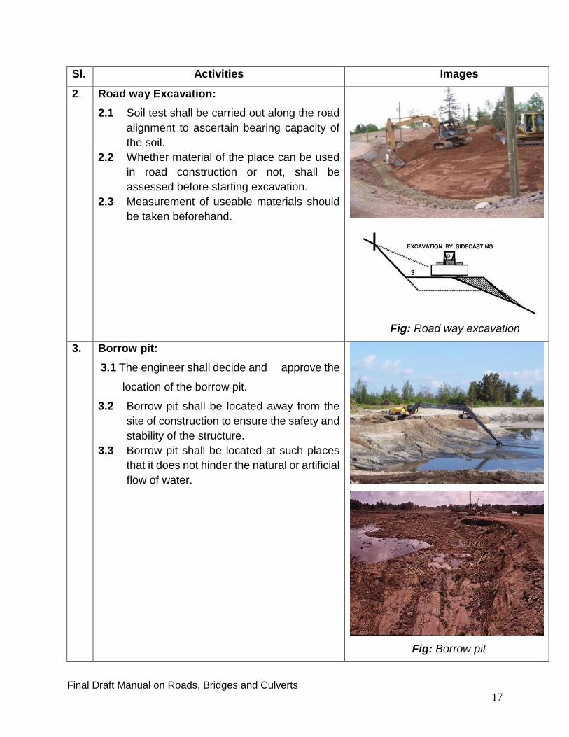
2. Road way Excavation:
2.1 Soil test shall be carried out along the road
alignment to ascertain bearing capacity of
the soil.
2.2 Whether material of the place can be used
in road construction or not, shall be
assessed before starting excavation.
2.3 Measurement of useable materials should
be taken beforehand.
Fig: Road way excavation
3. Borrow pit:
3.1 The engineer shall decide and approve the
location of the borrow pit.
3.2 Borrow pit shall be located away from the
site of construction to ensure the safety and
stability of the structure.
3.3 Borrow pit shall be located at such places
that it does not hinder the natural or artificial
flow of water.
Fig: Borrow pit

Final Draft Manual on Roads, Bridges and Culverts
18
Sl. Activities Images
4. Road embankment materials:
4.1 Earth fill materials shall be free from roots,
shrubs, grass and grass roots, structures
etc.
4.2 Shall be approved by the Engineer as a
suitable material for the purpose.
4.3 CBR of embankment material shall be more
than 3%.
4.4 Embankment materials, when compacted
shall achieve 95% maximum dry density
(MDD) determined in accordance with
Standard Testing Procedure (STP).
4.5 One compaction test shall be carried out for
each 1000 sq. meters of completed layer
according to STP.
Fig: Road embankment materials
5.
Road embankment:
5.1 After clearing the area cross section of the
original land, its approval should be taken
before start of work.
5.2 Embankment should be constructed in
150mm compacted layers and it should be
parallel to the last compacted layer. This will
remove water from the embankment easily.
5.3 Before spreading a new layer, the engineer
must approve the last compacted layer.
5.4 Spongy materials should be removed from
the embankment to get the desired
compaction result.
5.5 Places like ponds, marshes and canals in
the alignment should be cleared and sand-
filled, to strengthen the embankment. When
this filled land shall be raised to a designed
height level, it shall be compacted.
Fig: Road embankment

Final Draft Manual on Roads, Bridges and Culverts
19
Sl. Activities Images
6. Subgrade:
6.1 150mm layer above the earth layer or just
below the pavement is known as Subgrade.
6.2 Subgrade preparation with suitable soil and
proper compaction.
6.3 Subgrade is spread through entire breadth of
the embankment including shoulder.
6.4 During construction of embankment on an
existing road, entire earth up to 150mm depth
should be removed so that new materials are
completely mixed with the old materials.
6.5 Subgrade layers should be compacted to
achieve 98% of maximum dry density (MDD).
6.6 Subgrade should have LL<50%, PI<15% and
CBR>5%or as specified in the contract
document
6.7 The depth of upper part of the prepared
subgrade should be at least 50mm
everywhere. The variation in subgrade at any
place should not exceed ±20mm.
6.8 The contractor must take approval of the
subgrade before starting work of the
pavement.
Fig: Subgrade preparation
Final Draft Manual on Roads, Bridges and Culverts
20
Sl. Activities Images
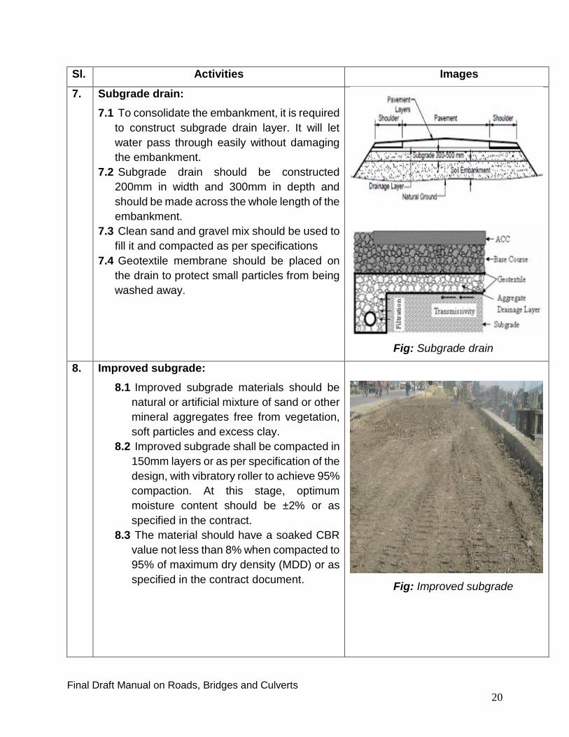
7. Subgrade drain:
7.1 To consolidate the embankment, it is required
to construct subgrade drain layer. It will let
water pass through easily without damaging
the embankment.
7.2 Subgrade drain should be constructed
200mm in width and 300mm in depth and
should be made across the whole length of the
embankment.
7.3 Clean sand and gravel mix should be used to
fill it and compacted as per specifications
7.4 Geotextile membrane should be placed on
the drain to protect small particles from being
washed away.
Fig: Subgrade drain
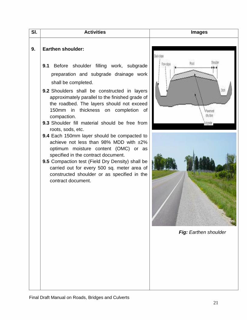
8. Improved subgrade:
8.1 Improved subgrade materials should be
natural or artificial mixture of sand or other
mineral aggregates free from vegetation,
soft particles and excess clay.
8.2 Improved subgrade shall be compacted in
150mm layers or as per specification of the
design, with vibratory roller to achieve 95%
compaction. At this stage, optimum
moisture content should be ±2% or as
specified in the contract.
8.3 The material should have a soaked CBR
value not less than 8% when compacted to
95% of maximum dry density (MDD) or as
specified in the contract document.
Fig: Improved subgrade
Final Draft Manual on Roads, Bridges and Culverts
21
Sl. Activities Images
9.
Earthen shoulder:
9.1 Before shoulder filling work, subgrade
preparation and subgrade drainage work
shall be completed.
9.2 Shoulders shall be constructed in layers
approximately parallel to the finished grade of
the roadbed. The layers should not exceed
150mm in thickness on completion of
compaction.
9.3 Shoulder fill material should be free from
roots, sods, etc.
9.4 Each 150mm layer should be compacted to
achieve not less than 98% MDD with ±2%
optimum moisture content (OMC) or as
specified in the contract document.
9.5 Compaction test (Field Dry Density) shall be
carried out for every 500 sq. meter area of
constructed shoulder or as specified in the
contract document.
Fig: Earthen shoulder

Final Draft Manual on Roads, Bridges and Culverts
22
Sl. Activities Images
10. Sub base material:
10.1 Sub-base construction with well graded
brick aggregates (with various shape and
sizes) and sand mixed shall be done and
compacted or it shall be done as specified
in the contract.
10.2 Sub-base materials should be natural or
artificial aggregate material, free from
vegetation, soft particles and excess clay.
The material shall fully conform to the
specifications and must have approval of
the Engineer.
10.3 The material should have 4-day soaked in
water and CBR value>25%when compared
to 98% MDD or it shall have value as
specified in the contract.
10.4 Aggregate crushing value (ACV) <38% and
ten percent fine value (TFV)> 75kN or shall
have value as specified in the contract.
10.5 Contractor Shall submit all the test results
for the engineer’s approval
Fig: Sub base material
Final Draft Manual on Roads, Bridges and Culverts
23
Sl. Activities Images
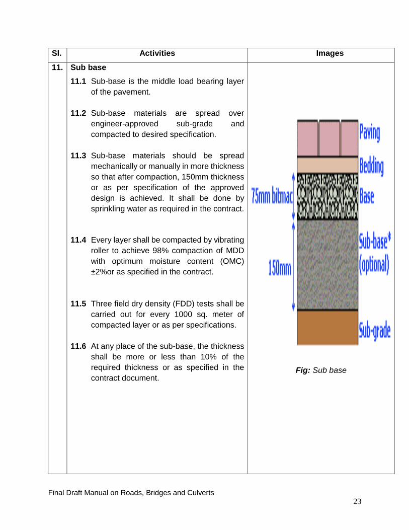
11. Sub base
11.1 Sub-base is the middle load bearing layer
of the pavement.
11.2 Sub-base materials are spread over
engineer-approved sub-grade and
compacted to desired specification.
11.3 Sub-base materials should be spread
mechanically or manually in more thickness
so that after compaction, 150mm thickness
or as per specification of the approved
design is achieved. It shall be done by
sprinkling water as required in the contract.
11.4 Every layer shall be compacted by vibrating
roller to achieve 98% compaction of MDD
with optimum moisture content (OMC)
±2%or as specified in the contract.
11.5 Three field dry density (FDD) tests shall be
carried out for every 1000 sq. meter of
compacted layer or as per specifications.
11.6 At any place of the sub-base, the thickness
shall be more or less than 10% of the
required thickness or as specified in the
contract document.
Fig: Sub base

Final Draft Manual on Roads, Bridges and Culverts
24
Sl. Activities Images
12. Base material (Aggregate):
There are two type of aggregate bases that are
constructed. These bases are classified as Base
Type I and Base Type II, depending on the basis
of materials used. These are as follows:
Base Type I - It is constructed with crushed stone
fragments with proportionate mix
of sand or stone dust.
Base Type II- It is constructed with crushed brick
fragments with proportionate mix
of sand or stone dust.
12.1 Base materials shall be mixed of all size and
shapes of aggregates i.e. it shall be well
graded.
12.2 When tested in accordance with STP, the
material shall have a minimum soaked CBR
value at a compaction of 98% of MDD as
determined by STP as follows:
Base Type I - 80%
Base Type II - 50%
12.3 Aggregate Crushing Value (ACV) shall be
less than 30% for Base Type I and 35% for
Base Type II or other test values as specified
in the contract.
12.4 Contractor shall obtain approval of all the
test results of Base materials from the
Engineer.
Fig: Aggregate base material

Final Draft Manual on Roads, Bridges and Culverts
25
Sl. Activities Images
13. Aggregate base ( laying):
13.1 Aggregate and sand shall be mixed
thoroughly to obtain homogenous mix and
water shall be added to keep mixed material
moist and spread over the surface. Each
layer shall be compacted (by vibrating
hammer) to at least 98% of the MDD as
determined by STP.
13.2 Density of the compacted aggregate base
course shall be determined in accordance
with STP (150 mm or 200 mm depending on
layer thickness of design) with at least 3 tests
to be carried out for each 1000 square
meters
13.3 Final shaping and rolling of the shoulder to
the full width shall be made after the base
course is completed
Fig: Aggregate base
14. Pavement Construction:
14.1 Pavements are generally of two types.
These are:
a. Rigid Pavement and
b. Flexible Pavement
a. Rigid pavement: This pavement is made of
R.C.C. or C.C. Although it is considered ideal
in the weather condition like Bangladesh
where rainy season is long and flooding is
quite common phenomena. But very small
portion of total KM of road is made of rigid
pavement. Normally roads in hat and bazar
where water logging is common and roads
Fig: Pavement (surface course)

Final Draft Manual on Roads, Bridges and Culverts
26
Sl. Activities Images
that remain submerged during rainy season
are made of R.C.C. or C.C. Construction cost
per KM of this type of road said to be a bit
higher compare to the cost of flexible
pavement, but its (rigid pavement)
maintenance cost is very low.
b. Flexible pavement: Different types of
surfacing are done for the subgrade, improved
subgrade and base. Popular flexible
pavements are bituminous or asphalt.
Sometimes on top of the pavement, sealing is
done by bituminous seal coat.
Generally a bituminous wearing course is applied
on the top of asphalt concrete. Depending on
requirement of the design, top surface of the road
pavement is made. Construction of road
pavement involves various parameters of highly
technical nature. Before starting work, the
contractor shall submit in writing to the engineer
a job-mix formula for each type of proposed
asphaltic mixture. This shall state the sources
and types of various materials to be used, the
mixing proportions of the various constituents, the
method of mixing, the method of heating bitumen
and aggregate sand the means of transportation,
laying and compaction. The formula so submitted
shall stipulate a single definite temperature for the
emptying of the mixture from the mixer, and for
mixture to be laid hot, a single definite
Fig: .Earth work during Laying
pavement works
Fig: .Laying geo-grid before placing
earthen layers during pavement woks.

Final Draft Manual on Roads, Bridges and Culverts
27
Sl. Activities Images
temperature at which the mixture is to be
delivered on the road. The job-mix formula for the
mixture shall indicate the percentage of
aggregate passing each required sieve size and
the percentage of bitumen to be added to the
aggregate.
The contractor shall not commence bitumen
surfacing work until the job-mix formula has
been approved in writing by the Engineer,
including any adjustment to the job mix
formula which the Engineer considers are
necessary.
A checklist on construction of bituminous
pavement is developed and attached as
Checklist Annexure-5, page-58 at the end of the
chapter that may be useful for IMED for the
purpose of inspection of pavement construction.
Apart from this, a short illustration of frequently
used terms in bituminous pavement work is also
given below:
Prime Coat: The principal function of prime coat
in bituminous pavement is to protect the
subgrade from moisture and weathering. Since
the presence of moisture affects the strength of
subgrade, the prevention of water entry during
construction is essential to avoid the failure of the
pavement. Prime coat is an asphalt which, when
applied evenly to the surface of sub-base or
subgrade, serves to seal the surface to hinder the
penetration of moisture into subgrade. Vehicular
traffic should be avoided on the
Fig: Bitumen Spraying

Final Draft Manual on Roads, Bridges and Culverts
28
Sl. Activities Images
surface sprayed with prime coat because the
traction and tearing action of vehicles would
damage this asphalt layer.
Following steps shall be taken before spreading
bituminous layer over the surface:
The Prime Coat layer shall be sprayed on
completely dried and cleaned surface as per
specifications or as per instruction of the
engineer.
Bitumen mix shall not be spread until Prime
Coat layer is completely dried.
The surface area shall be thoroughly cleaned
before applying bitumen or bituminous layer.
When upper surface is completely dried,
possibility of rain is remote and condition of
Road Bed is satisfactory then only bitumen
mix layer shall be spread as per instruction of
the engineer.
Bituminous surfacing layer shall be compacted
quickly by a specified roller to achieve result
as per specifications.
The work shall consists of cleaning of the surface
to be Prime Coated and applying bituminous
material in accordance with the specifications or
as directed by the engineer
Tack Coat: Tack coat is applied after the prime
coat, to form an adhesive bond between the tack
coat and the next layer of coating. The tack coat
prevents slippage and may sometimes function
as a more long-term sealer.
The work shall consists of applying bituminous
material to a previously prepared Road Bed, in
accordance with the specifications and to the
width and the area required by the engineer.
Fig: Laying of pavement work
Final Draft Manual on Roads, Bridges and Culverts
29
10. Stages of Bridge Construction
10.1 Essential tests and equipment required to ensure quality
It has been mentioned earlier that quality achievement is not an easy outcome or an
accident; it is the product of determined effort. The PD/PE is the key person who must
play an important role to get the works done true to the standards and specifications so
as to ensure desired quality of work. The contractor is obligated under the contract for
testing of the quality of work to ensure compliance as stipulated in the specifications. It is
the standard practice for the engineer’s site staff to supervise and witness such testing of
the works. However, the site engineer should also carry out some testing separately, for
the purpose of validation of tests done by the contractor as well as for the auditing
purposes. In case of construction of bridges and culverts following tests and steps are
required to be followed:
Tests of Materials: In case of materials Particle Size Distribution (PSD),
Aggregate Crushing Value (ACV), Flakiness Index tests and
Elongation/Tensile strength/Bend tests for MS bar or any other tests as
instructed by the engineer shall be carried out and approval of the engineer shall
be obtained by the contractor for the source of supply of materials and the Brand
(if any).
Tests of Concrete: During different stages of construction of bridges and culverts
frequent tests of concrete mix like Workability-Slump/Cylinder test and
Compressive Strength tests shall be performed by the contractor as required by
the contract document or as instructed by the engineer and shall obtain approval
of the engineer and then proceed further as per instruction of the authority.

Final Draft Manual on Roads, Bridges and Culverts
30
Test of Pile: A Pile Integrity Test (also known as low strain dynamic test, sonic
echo test, and low strain integrity test) and Load Test shall be carried out by
the contractor to determine its length, designed strength and other required
features and obtain approval of the engineer before commencing the Service Pile
work.
Curing: Curing shall be started immediately after thumb set of the concrete laid.
Hessian clothe /Plastic shall be covered over the set concrete to reduce moisture
evaporation from the concrete during hardening and thus to minimize shrinkage
crazy cracks. These cracks are inheriting property of the concrete that appears
during casting of flat surfaces.
Curing water should be as per specification and curing shall be carried out as
specified in the contract.
Use of Equipment: Depending on the volume of work and requirement of the
contract construction equipment like Mixer Machine, Batching Plant etc. shall be
made available by the contractor prior to start of work. Vibrator machine shall be
used in concreting work to ensure proper compaction and achieve desired result
as per specifications of the contract.

Final Draft Manual on Roads, Bridges and Culverts
31
10.2 Bridge construction Stages:
Sl.no
Activities Images
1. Soil test: Conducting Soil Test of a selected
place is necessary to know conditions of soil
beneath the surface to obtain full information
on the type, size, length and capacity of the
piles. Designer of the Pile takes into
consideration the result of the soil test and
fixes its parameters.
Figure: Soil Test
2. Test Piling: There are various types of piles
which are designed for massive structures.
These are Driven Pile, Cast in Place Piles /
Board Piles, Prefabricated Piles etc. The
most used types are Bored piles and
Prefabricated Piles. It can be constructed
using a number of methods. The simplest
method for Bored Pile construction is to use
an auger to remove the soil and replace it
with concrete and reinforcement and
Prefabricated Piles are carried to the
specified place and is mechanically driven to
a designed depth or as per instruction of the
engineer
Pile load tests are generally performed to
either prove that piles are capable of
sustaining the ultimate design load ("proof
Figure: Boring hole for Piles
Figure: Pile Reinforcement

Final Draft Manual on Roads, Bridges and Culverts
32
Sl.no
Activities Images
test") or to gain more detailed information
that will enable a more efficient design. For
a proof test, a test pile is loaded to the
ultimate design load (allowable design load
times the factor of safety) and the deflection
is measured at the pile head. If the deflection
is within allowable levels, the test has
“proved” that the pile is acceptable. Proof
tests are generally performed during
construction as the piles are installed.
Stages of pile work are as follows:
a. Boring
b. Reinforcement preparing and
lowering in the bore hole
c. Concrete pouring
d. Pile load test
Figure: Pile reinforcement lowering in hole
Figure: Concrete pouring
Figure: Pile load test
Final Draft Manual on Roads, Bridges and Culverts
33
Sl.no
Activities Images
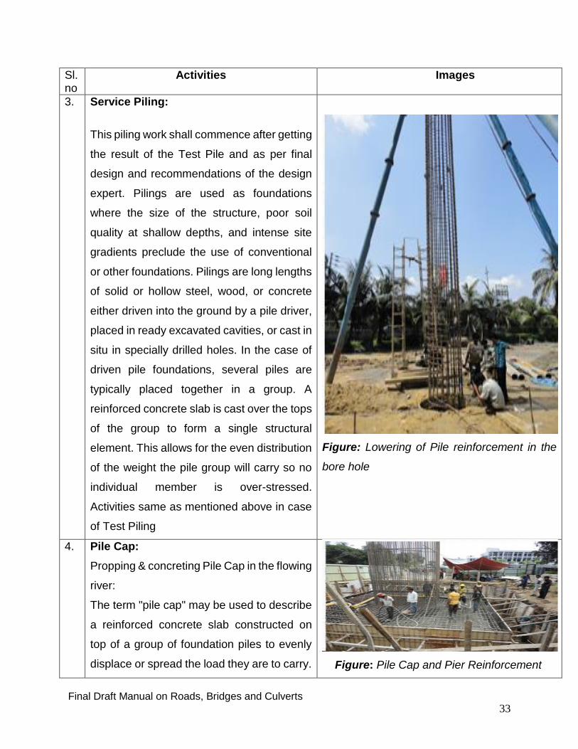
3. Service Piling:
This piling work shall commence after getting
the result of the Test Pile and as per final
design and recommendations of the design
expert. Pilings are used as foundations
where the size of the structure, poor soil
quality at shallow depths, and intense site
gradients preclude the use of conventional
or other foundations. Pilings are long lengths
of solid or hollow steel, wood, or concrete
either driven into the ground by a pile driver,
placed in ready excavated cavities, or cast in
situ in specially drilled holes. In the case of
driven pile foundations, several piles are
typically placed together in a group. A
reinforced concrete slab is cast over the tops
of the group to form a single structural
element. This allows for the even distribution
of the weight the pile group will carry so no
individual member is over-stressed.
Activities same as mentioned above in case
of Test Piling
Figure: Lowering of Pile reinforcement in the
bore hole
4. Pile Cap:
Propping & concreting Pile Cap in the flowing
river:
The term "pile cap" may be used to describe
a reinforced concrete slab constructed on
top of a group of foundation piles to evenly
displace or spread the load they are to carry.
Figure: Pile Cap and Pier Reinforcement

Final Draft Manual on Roads, Bridges and Culverts
34
Sl.no
Activities Images
It can also refer to plastic or glass fiber caps
placed over the tops of wooden pilings to
protect them against rot and to stop birds
nesting on the pilings. Most commonly,
however, the term refers to the concrete slab
that is cast on concrete or steel pilings once
they have been suitably trimmed and
prepared. These slabs offer a larger area for
the construction of the columns they support
and also help spread the weight of the
structure over all pilings in a group allowing
them to better support the load.
Figure: Pile cap in flowing river
5. Abutment & Wing Wall:
Its construction is similar to that of building
construction. Abutments are designed to rest
two ends of a bridge, whereas Wing Walls
are designed to protect earth from sliding. It
also acts as load transferring structure from
the bridge to the ground. Figure: Abutment & Wing Wall
6. Scaffolding:
Scaffolding is used to build platform to
support working men and materials.
All scaffolding must be erected, dismantled
and altered in a safe manner. This is
achieved by following the guidance provided
by the expert in the field or by following
guidance provided by the manufacturers of
system scaffolding.
Figure: Scaffolding

Final Draft Manual on Roads, Bridges and Culverts
35
Sl.no
Activities Images
7. PC Girder:
Activities same as mentioned above in case
of Test Piling.
A PC box girder bridge is a bridge in which
the main beams comprise girders in the
shape of a hollow box. The box girder
normally comprises either pre-stressed
concrete, structural steel, or a composite of
steel and reinforced concrete. The box is
typically rectangular or trapezoidal in cross-
section. Box girder bridges are commonly
used for highway flyovers and for modern
elevated structures of light rail transport.
Although normally the box girder bridge is a
form of beam bridge, box girders may also
be used on cable-stayed bridges and other
forms.
If made of concrete, box girder bridges may
be cast in place using false work supports,
removed after completion, or in sections if a
segmental bridge. Box girders may also be
prefabricated in a fabrication yard, then
transported and emplaced using cranes.
Careful handling of the PC Girder shall be
ensured as per instruction of the engineer.
Figure: PC Girder pre-fabrication
Figure: PC Girder in position

Final Draft Manual on Roads, Bridges and Culverts
36
Sl.no
Activities Images
8. Expansion Joint:
A Bridge Expansion Joint is a structural
component designed to provide smooth
passage over the gap between adjacent
sides of a deck joint and thus allow for
continuous traffic between structures
accommodating movement, concrete
shrinkage or creep, elastic shortening due to
pre-stressing, temperature variations on
reinforced and pre-stressed concrete,
composite and steel structures. They stop
the bridge from bending out of place in
extreme conditions and allow enough
vertical movement to permit bearing
replacement without the need to dismantle
the bridge expansion joint.
Figure: Concrete Bridge Expansion Joint
9. Deck Slab construction:
Deck slab is used for movement of traffic. It
transfers traffic load to the round through
piles. Its construction method is similar to
that of slab casting of a building.
Pouring of concrete shall be made as per
instruction and guidance of the engineer.
Proper walkways/platforms shall be
arranged so that the supports of the pipeline
and manpower do not directly stand on
reinforcement.
Sufficient carpenters along with supervisor
shall inspect the behavior of supports below
the slab during the casting. Extra Props shall
be stocked below slab to provide additional
supports in case of any failure of supports.
Figure: Deck Slab construction
Final Draft Manual on Roads, Bridges and Culverts
37
Sl.no
Activities Images
10
.
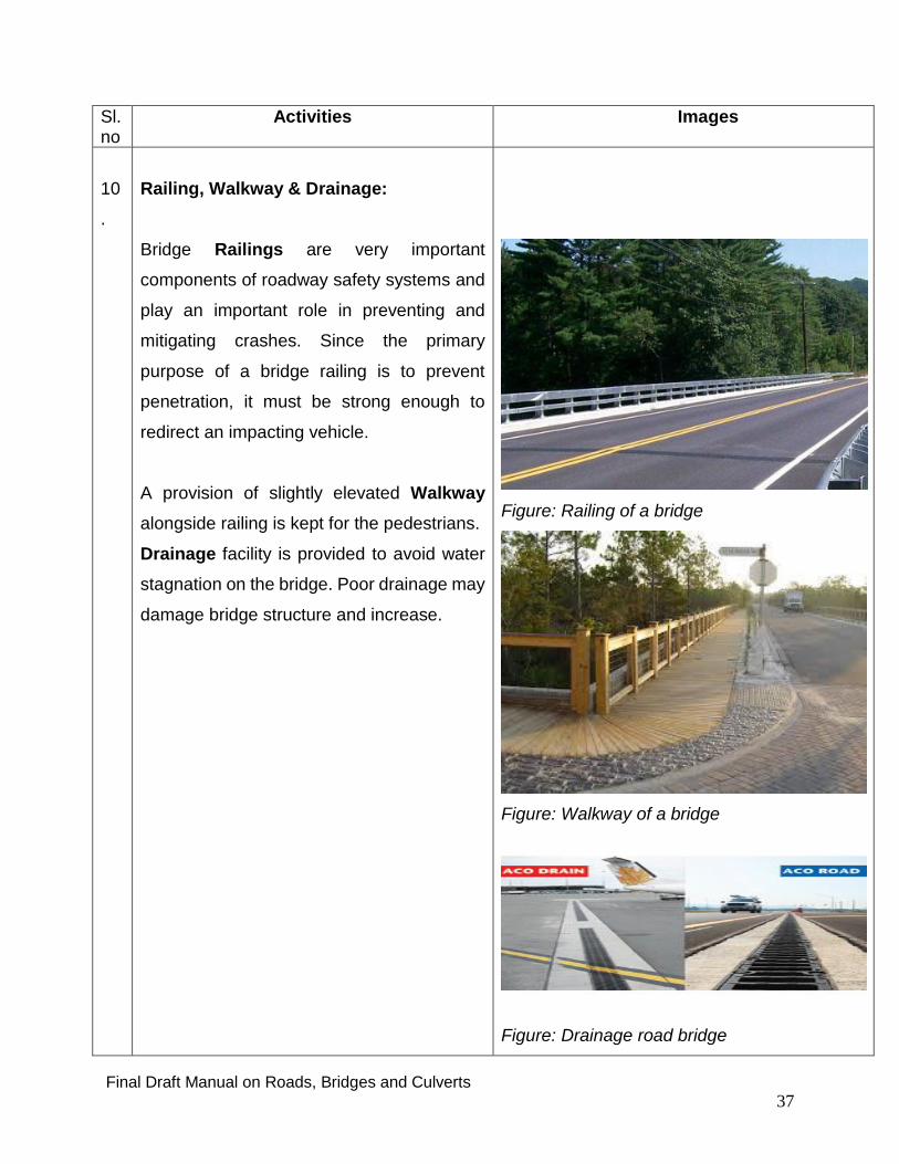
Railing, Walkway & Drainage:
Bridge Railings are very important
components of roadway safety systems and
play an important role in preventing and
mitigating crashes. Since the primary
purpose of a bridge railing is to prevent
penetration, it must be strong enough to
redirect an impacting vehicle.
A provision of slightly elevated Walkway
alongside railing is kept for the pedestrians.
Drainage facility is provided to avoid water
stagnation on the bridge. Poor drainage may
damage bridge structure and increase.
Figure: Railing of a bridge
Figure: Walkway of a bridge
Figure: Drainage road bridge

Final Draft Manual on Roads, Bridges and Culverts
38
Sl.no
Activities Images
11 Electrification: Illumination of a bridge and
its approaches through installation of
electrical system is a part and parcel of the
entire bridge construction/design activities.
Proper illumination increases visibility of the
bridge environment and safety of the
commuters. It also lessens chances of traffic
accidents and ensures safe movements of
pedestrians on the bridge.
Figure: Electrification of bridge
12 Approach Road:
Without properly completing approach road
of a bridge or culvert, the purpose of its
construction remains unfulfilled. Therefore,
utmost care is necessary to complete its
construction along with completion of
construction of bridge or culvert to ensure its
benefit to the common people.
Figure: Approach road construction

Final Draft Manual on Roads, Bridges and Culverts
39
11. Stages of Culvert’s Construction:
11A. Component of Culvert
Bottom slab
Cut-off-wall
Vertical wall
Wing wall
Top slab
Protective works (special cases)
11B. Construction steps of Culverts:
Setting vertical and horizontal alignment.
Box cutting.
Concreting of base slab with cut-of-wall.
Concreting vertical wall with wing wall.
Backfilling
Bottom slab
Cut-off-wall/ Scour pad
Abutment/ vertical wall
Wing wall
Top slab

Final Draft Manual on Roads, Bridges and Culverts
40
12. Study of Project Document:
An approved Development Project Proforma (DPP) is considered to be the Bible to be
followed by everybody in its letter and spirit. It is the document that contains the physical
and non-physical items of works along with its budgetary provisions and also its execution
plan to be carried out over the project implementation period. An inspector should also
have comprehensive knowledge of this approved government document as to what are
the physical activities to be taken up for implementation by the project management.
Study of the project document thoroughly, particularly the work components that are
planned to be inspected with reference to previous inspection/progress report (See
Annexure-1; page 44-46 and Annexure-2 page 47-48 for DPP/TPP Checklists) is
necessary.
13. Study of procurement discipline:
Beside other documents, it is advisable to study in depth on the PPA 2006 and the PPR
(See Annexure-3; page 49-52 procurement discipline Checklist). Without having
comprehensive knowledge of this aforesaid Acts and Rules with checklists one may be
misguided while visiting the project site. The documents and the checklists will give one
an insight into the detail of the work awarded to the contractor.
14. Study of roads related technical discipline:
Before investigation of roads related projects which are purely known as civil works, one
should remember the basic engineering roles item by item. For example rate Schedule of
all kind of materials. See Annexure-4, page 53-57; road related technical discipline
Checklist.
15. Study of Project implementation arrangements:
All the project documents have an approved provision of required number of, different
categories of project personnel for execution of the project as well as for its operation
after its completion. IMED’s inspecting official should take stock of the whole arrangement
and see whether these positions are filled up. Organizations like PWD, PDB, WDB, R &
H D etc. government and autonomous bodies normally do not recruit new personnel for
Final Draft Manual on Roads, Bridges and Culverts
41
the project from outside; rather it depute project personnel including PD, from within the
organization. If project execution personnel are appointed from outside through open
advertisement, IMED may see whether procedures for recruitment of manpower were
properly followed and recruited personnel possessed requisite qualifications and
experience as stipulated in the DPP/TAPP.
Appointment of full time PD, though very important for timely project implementation, but
government decision in this respect is often overlooked/neglected by the ministry/agency
and part time PD is appointed. IMED’s inspecting official may obtain detail information
about the appointment of the PD and also note whether project progress or quality of work
in anyway suffered due to appointment of a part time PD or shortage of manpower in this
project.
16. Checking quality of work:
Basic responsibility of ensuring quality of work lies with the contractor. The contractor has
to ensure supply of construction materials as per specifications of the contract and also
to ensure its use and workmanship as mentioned in the contract document. The indenting
agency/ministry has to ensure that whatever was specified in the contract document is
being delivered by the contractor. IMED as an outsider can do little to ensure quality of
work from the contractor, but it can certainly help agency/ministry in extracting quality
work and better workmanship through regular visits to the project sites. But in most cases
IMED’s field inspection takes place after completion of the work that does not help ensure
quality of work. Therefore, depending on the stage of progress of work in the field IMED’s
visits has to be planned.
16. A Establishing site office and on-site testing facilities:
To fulfill the conditions of the contract and facilitate smooth construction activities, a
contractor is required to builds a site office nearest to the project location. Creation of
material and quality testing facilities at site at the cost of contractor also remains part of
the contract.
Final Draft Manual on Roads, Bridges and Culverts
42
Site office is built by the contractor in a way that it accommodates PD’s office and his staff
as well. Provision of electricity and water supply is also ensured by the contractor to
smoothen activities of the project without interruption. At the site office, contractor’s
essential men and construction materials and equipment are also located.
16. B Maintenance of site inspection register/book:
Contractor is required to maintain a ‘site inspection register/book’ on the site, and also
preserve a copy of the ‘Work Order’ along with it, so that visiting project officials and other
related officials can write their observations/instructions in it, regarding progress of work,
mobilization of equipment and materials, quality of material as well as quality of work
performed (workmanship) by the contractor. He is also required to supply construction
schedule and keep a copy of it at project site for quick reference and observations. These
are considered prerequisite steps for the start of construction work. Therefore, when
visiting a site, take a look into this ‘book’. That will give first-hand information about the
frequency of visits by senior project officials and other related officials at site, instructions
given to the contractor for compliance and its follow status up etc. IMED official may also
record his comments/observations in the ‘book’ regarding his visit and other issues that
deem worth mentioning and can desire to be on record for future ready reference.
16. C Use of visual aid during inspection:
Visual aid like Camera or Video Recorder may be used for recording images of project
activities. These images will always be helpful in better understanding the project situation
in the field. In many cases, it will complement comments/observations of the officials and
confirm reliability of information and data collected from the field. Therefore, wherever
possible, help of visual aid should be sought for explaining views/comments/observations.
Photographs of the structure from different angles and the photographs of the
construction defects like hair cracks or larger cracks in slabs, honeycombs or cracks in
pillars etc. and defects in in other areas of construction will strongly complement
inspecting official’s views and comments.
Final Draft Manual on Roads, Bridges and Culverts
43
17. Removal of temporary structures and backfilling:
After completion of the construction work, contractor is required to remove the temporary
structures and make necessary backfill of earth and restore the ground to its original
surrounding position. It is observed that the contractors often leave the site without
properly backfilling, removing the temporary structures and leveling the ground, causing
serious damage to the road embankment and concrete structures. These temporary
structures include diversion road constructed for facilitating construction of small bridges
and culverts or construction of temporary structures in the river to facilitate the
construction of a long bridge etc. Unwanted structures in the river sometimes cause
scouring and threaten stability of the bridge.
18. Conclusion:
The quality achievement is not an easy outcome or an accident; it is the product of
determined effort. The PD/PE is the key person who must play an important role to get
the work s done true to the standards and specifications so as to ensure desired quality
of work. The contractor is obligated under the contract for testing of the quality of work to
ensure compliance as stipulated in the specifications. It is the standard practice for the
engineer’s site staff to supervise and witness such testing of the works. However, the site
engineer should also carry out some testing separately, for the purpose of validation of
tests done by the contractor as well as for the auditing purposes.
The inspecting officials from the Ministry/Department and the IMED may verify whether
or not the contractual obligations of the contract have been fulfilled with proper
documentation of the test results and comments of the site/Project Engineer there on.
This must be carefully noted and reported at the decision making level of the government.
Final Draft Manual on Roads, Bridges and Culverts
44
Annexure-1
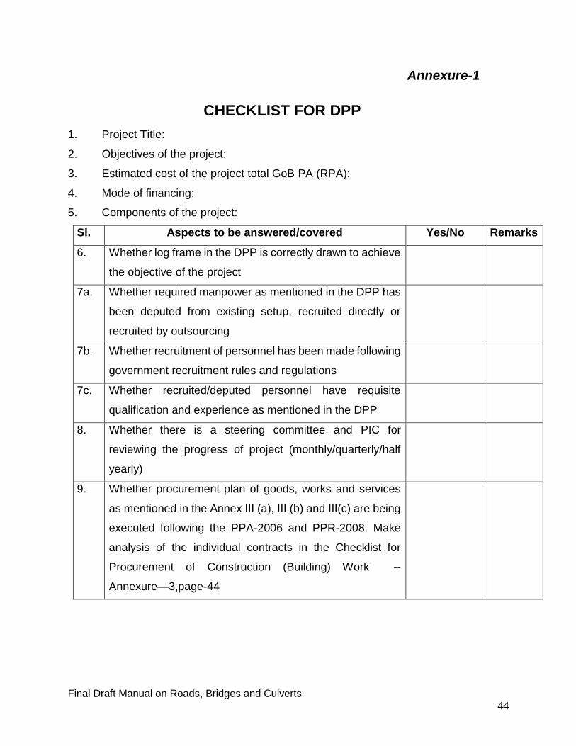
CHECKLIST FOR DPP
1. Project Title:
2. Objectives of the project:
3. Estimated cost of the project total GoB PA (RPA):
4. Mode of financing:
5. Components of the project:
Sl. Aspects to be answered/covered Yes/No Remarks
6. Whether log frame in the DPP is correctly drawn to achieve
the objective of the project
7a. Whether required manpower as mentioned in the DPP has
been deputed from existing setup, recruited directly or
recruited by outsourcing
7b. Whether recruitment of personnel has been made following
government recruitment rules and regulations
7c. Whether recruited/deputed personnel have requisite
qualification and experience as mentioned in the DPP
8. Whether there is a steering committee and PIC for
reviewing the progress of project (monthly/quarterly/half
yearly)
9. Whether procurement plan of goods, works and services
as mentioned in the Annex III (a), III (b) and III(c) are being
executed following the PPA-2006 and PPR-2008. Make
analysis of the individual contracts in the Checklist for
Procurement of Construction (Building) Work --
Annexure—3,page-44
Final Draft Manual on Roads, Bridges and Culverts
45
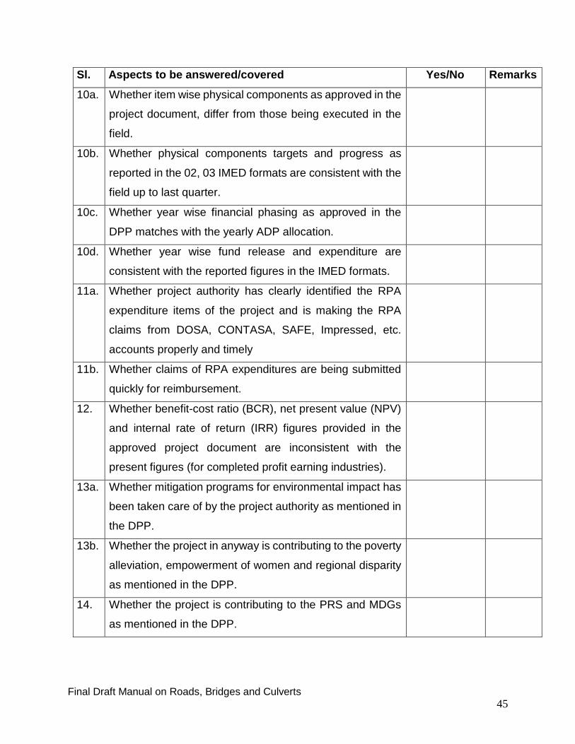
Sl. Aspects to be answered/covered Yes/No Remarks
10a. Whether item wise physical components as approved in the
project document, differ from those being executed in the
field.
10b. Whether physical components targets and progress as
reported in the 02, 03 IMED formats are consistent with the
field up to last quarter.
10c. Whether year wise financial phasing as approved in the
DPP matches with the yearly ADP allocation.
10d. Whether year wise fund release and expenditure are
consistent with the reported figures in the IMED formats.
11a. Whether project authority has clearly identified the RPA
expenditure items of the project and is making the RPA
claims from DOSA, CONTASA, SAFE, Impressed, etc.
accounts properly and timely
11b. Whether claims of RPA expenditures are being submitted
quickly for reimbursement.
12. Whether benefit-cost ratio (BCR), net present value (NPV)
and internal rate of return (IRR) figures provided in the
approved project document are inconsistent with the
present figures (for completed profit earning industries).
13a. Whether mitigation programs for environmental impact has
been taken care of by the project authority as mentioned in
the DPP.
13b. Whether the project in anyway is contributing to the poverty
alleviation, empowerment of women and regional disparity
as mentioned in the DPP.
14. Whether the project is contributing to the PRS and MDGs
as mentioned in the DPP.

Final Draft Manual on Roads, Bridges and Culverts
46
Sl. Aspects to be answered/covered Yes/No Remarks
15. Whether any project aid conditionality mentioned in the
DPP is affecting implementation of the project.
16a. Whether rehabilitation/resettlement of affected
persons/families program is taken up by the project
authority.
16b. Whether the cost involvement as mentioned in the DPP for
rehabilitation/resettlement will remain within the approved
estimate.
17. Whether project implementation period is likely to be
extended
18. Whether there is a possibility of time over run and cost over
run
19. Whether internal and external audits are being carried out.
When last internal and external audit was done.
20. Whether site register/book is being maintained at project
site and visiting supervisory officials are recording their
observations on progress and quality of work etc.
21. Whether Annual Work Plan has been prepared by the
project authority/PD.
22. Whether CPM/ Bar Chart, for smooth execution of the
project, has been prepared and being followed.
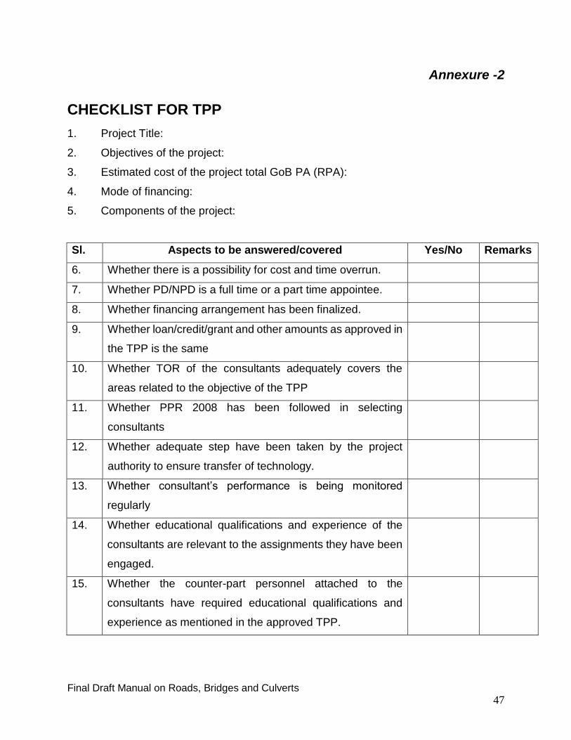
Final Draft Manual on Roads, Bridges and Culverts
47
Annexure -2
CHECKLIST FOR TPP
1. Project Title:
2. Objectives of the project:
3. Estimated cost of the project total GoB PA (RPA):
4. Mode of financing:
5. Components of the project:
Sl. Aspects to be answered/covered Yes/No Remarks
6. Whether there is a possibility for cost and time overrun.
7. Whether PD/NPD is a full time or a part time appointee.
8. Whether financing arrangement has been finalized.
9. Whether loan/credit/grant and other amounts as approved in
the TPP is the same
10. Whether TOR of the consultants adequately covers the
areas related to the objective of the TPP
11. Whether PPR 2008 has been followed in selecting
consultants
12. Whether adequate step have been taken by the project
authority to ensure transfer of technology.
13. Whether consultant’s performance is being monitored
regularly
14. Whether educational qualifications and experience of the
consultants are relevant to the assignments they have been
engaged.
15. Whether the counter-part personnel attached to the
consultants have required educational qualifications and
experience as mentioned in the approved TPP.

Final Draft Manual on Roads, Bridges and Culverts
48
Sl. Aspects to be answered/covered Yes/No Remarks
16. Whether educational qualification and experience of the
support staff matches with information provided in the
approved TPP.
17. Whether letter of agreement with implementing agency and
the development partner has been signed.
18. Whether project steering committee has been formed to
review the progress of work.
19. Whether auditing of the project is being carried out. When
the last audit was done?
20. Whether project work is progressing as per approved
implementation works schedule provided in the TPP.
21. Whether total procurement plan as envisaged in the
approved TPP is being implemented in the light of PPR
2008. Individual contracts should be analyzed in the
Checklist for Procurement of Construction (Building) Work -
-Annexure-3.
22. Whether approving authority is exercising financial authority
as per Delegation of Financial Power published by ministry
of finance.
23. Whether CPM/ Bar Chart, for smooth execution of the
project, has been prepared and being followed.

Final Draft Manual on Roads, Bridges and Culverts
49
Annexure -3
CHECKLIST FOR PROCUREMENT OF CONSTRUCTION
WORKS (RHD)
PART-A PROCURING ENTITY AND DESCRIPTION OF PROCUREMENT
1. Ministry/Division
2. Agency
3. Procuring Entity
4. Name of the Project (if applicable)
5. Source of Funds
(Tick relevant boxes)
Government Development Revenue
Project Aid Own Funds
6. Procurement Plan Status of Annual Procurement Plan (APP)
Approved Unapproved
Short Description (If necessary):
7. Brief Description of Works
8. Procurement Method (as
in DPP or otherwise)
9. Procurement Value
(Estimated Cost)
10. Type of Tender
Document
(Tick relevant one)
SRFQ (PW 1)
STD (PW 2/PW 3/PW 4/PW 5)
SPD (PQW 4/ PQW 5)
11. Formation of TOC/POC
and TEC/PEC
No of members in TOC/POC
No of member from TEC/PEC
No of members in TEC/PEC
No of external members in TEC/PEC
Authority approved TEC/PEC

Final Draft Manual on Roads, Bridges and Culverts
50
PART-B SCHEDULE OF ACTIVITIES ( Pre-Qualification)
Sl. Activity
(If not applicable indicate N/A)
Planned Date
(As per procurement plan/
Flow Chart)
Actual
Date
Remarks
1. PRE-QUALIFICATION
1.1 Date of Advertisement of Invitation
1.1.1 Advertisement in Newspaper Published
1.1.2 Advertisement in CPTU Website Published
1.1.3 Advertisement published in own website,
1.1.4 Tenders/Proposals followed PPA-2006/PPR, 2008
1.1.5 Tenders/Proposals followed DP’s Guidelines
1.1.6 No of Sale/Issuance of Tender/Proposal Documents
1.1.7 No of Tenderer/Consultant participated
1.1.8 Days allowed per Rule for preparation and Submission
1.1.9 Date of Submission of Tender Doc./Applications
1.2 Date of Pre-Qualification Meeting (if any)
2. Tenders/Proposals Evaluation
2.1 Days allowed per Rule between opening and completion/submission of evaluation
2.2 Days actual between opening and completion/submission of evaluation
2.3 Responsiveness of Tender/Proposal 2.4 Re-invitation of Tenders/Proposals
recommended by TEC/PEC 2.5 Procurement proceedings
annulled/cancelled 2.6 Date of Submission of Evaluation Report
with Recommended List
2.7 Approving Authority (AA) as per Delegation of Financial Power (DoFP)
2.8 Date of Approval of List 2.9 Authority approval date 2.10 Evaluation report was sent directly to
the AA

Final Draft Manual on Roads, Bridges and Culverts
51
PART-C SCHEDULE OF ACTIVITIES
Sl. Activity (If not applicable indicate N/A)
Planned Date
(As per procurement plan/
Flow Chart)
Actual Date
Remarks
1. TENDER FOR WORKS
1.1 Date of Advertisement of Invitation for Tenders
1.1.1 Advertisement in Newspaper Published
1.1.2 Advertisement in CPTU Website Published
1.1.3 Advertisement published in agency’s own website,
1.1.4 Tenders/Proposals followed PPA-2006, PPR-2008
1.1.5 Tenders/Proposals followed Dev. Partner’s Guidelines
1.2 Date of Issue of Tender Document
1.2.1 No of Sale/Issuance of Tender/Proposal Documents
1.2.2 No of Tenderer/Consultant participated
1.3 Date of Pre-Tender (Pre-Bid) meeting
1.3.1 Days allowed as per rules for preparation and Submission
1.3.2 Date of Submission of Tenders
1.4 Date of Opening of Tenders
1.5 Date of Submission of Technical Sub-Committee Report (if
applicable)
1.6 Date of Submission of Evaluation Report
1.7 Procurement processing lead-time i.e. days actual between opening
and issuance of NOA/PO/Contract signing/LOI
1.8 Days actual between IFT/RFP and issuance of NOA/PO/Contract
signing/LOI
1.9 Publication of award in CPTUs website/PE’s website/others
1.10 Contract award made within the initial Tender/Proposal validity
period
:
1.11 Date of Approval for Award of Contract :
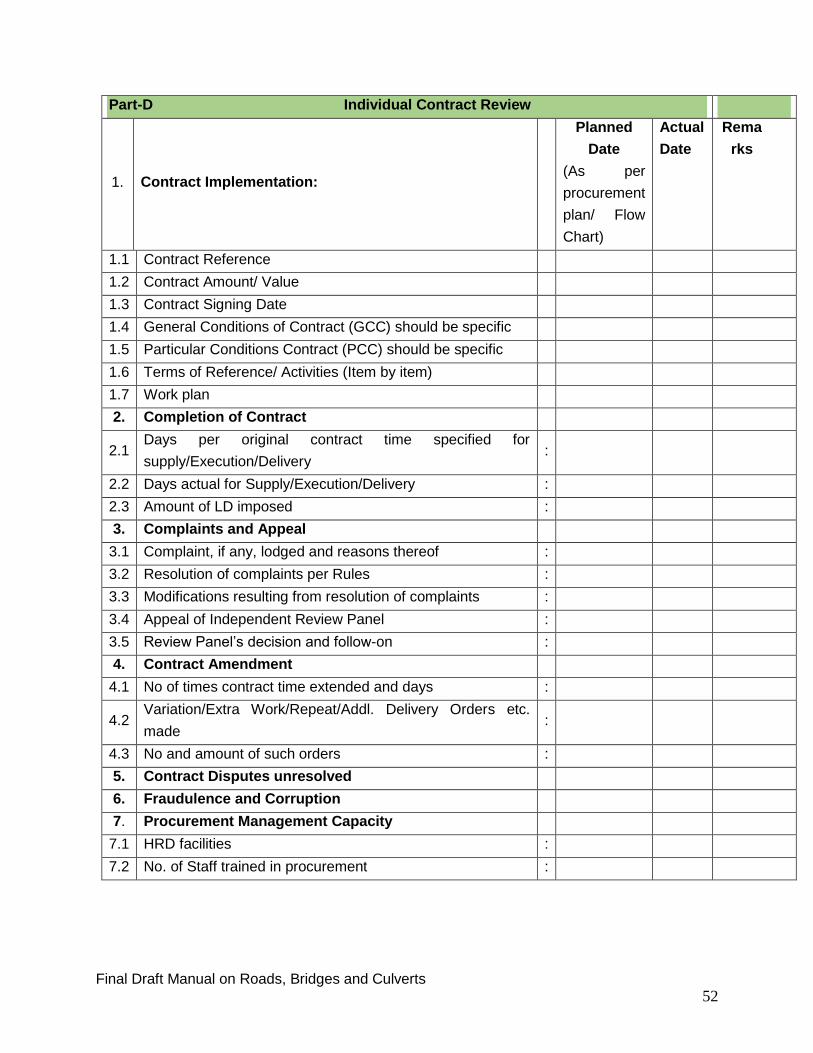
Final Draft Manual on Roads, Bridges and Culverts
52
Part-D Individual Contract Review
1. Contract Implementation:
Planned
Date
(As per
procurement
plan/ Flow
Chart)
Actual
Date
Rema
rks
1.1 Contract Reference
1.2 Contract Amount/ Value
1.3 Contract Signing Date
1.4 General Conditions of Contract (GCC) should be specific
1.5 Particular Conditions Contract (PCC) should be specific
1.6 Terms of Reference/ Activities (Item by item)
1.7 Work plan
2. Completion of Contract
2.1 Days per original contract time specified for
supply/Execution/Delivery :
2.2 Days actual for Supply/Execution/Delivery :
2.3 Amount of LD imposed :
3. Complaints and Appeal
3.1 Complaint, if any, lodged and reasons thereof :
3.2 Resolution of complaints per Rules :
3.3 Modifications resulting from resolution of complaints :
3.4 Appeal of Independent Review Panel :
3.5 Review Panel’s decision and follow-on :
4. Contract Amendment
4.1 No of times contract time extended and days :
4.2 Variation/Extra Work/Repeat/Addl. Delivery Orders etc.
made :
4.3 No and amount of such orders :
5. Contract Disputes unresolved
6. Fraudulence and Corruption
7. Procurement Management Capacity
7.1 HRD facilities :
7.2 No. of Staff trained in procurement :
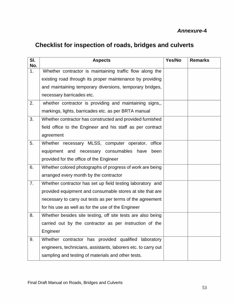
Final Draft Manual on Roads, Bridges and Culverts
53
Annexure-4
Checklist for inspection of roads, bridges and culverts
Sl. No.
Aspects Yes/No Remarks
1. Whether contractor is maintaining traffic flow along the
existing road through its proper maintenance by providing
and maintaining temporary diversions, temporary bridges,
necessary barricades etc.
2. whether contractor is providing and maintaining signs,,
markings, lights, barricades etc. as per BRTA manual
3. Whether contractor has constructed and provided furnished
field office to the Engineer and his staff as per contract
agreement
5. Whether necessary MLSS, computer operator, office
equipment and necessary consumables have been
provided for the office of the Engineer
6. Whether colored photographs of progress of work are being
arranged every month by the contractor
7. Whether contractor has set up field testing laboratory and
provided equipment and consumable stores at site that are
necessary to carry out tests as per terms of the agreement
for his use as well as for the use of the Engineer
8. Whether besides site testing, off site tests are also being
carried out by the contractor as per instruction of the
Engineer
9. Whether contractor has provided qualified laboratory
engineers, technicians, assistants, laborers etc. to carry out
sampling and testing of materials and other tests.

Final Draft Manual on Roads, Bridges and Culverts
54
Sl. No.
Aspects Yes/No Remarks
10. Whether contractor is maintaining site register book and
supervising officers are recording their comments/
observations in it
11. Whether source approval of material has been taken by the
contractor
12. Whether compaction test of the final layers have been
carried out and test results have been approved by the
Engineer
13. Whether construction materials are being tested in the
laboratory and then used by the contractor according to the
instruction and approval of the Engineer
14. Whether subgrade drain have been constructed and
covered with Geotextile Membrane as per drawings or as
per instruction of the Engineer.
15. Whether sub base and aggregate base layers have been
compacted to achieve the CBR values as per requirement
of the contract
16. Whether sub base and aggregate base materials have been
tested in the site laboratory and results have been okayed
by the Engineer.
17. Whether report on Asphalt Concrete pavement and test
reports on ‘Core’ sampling in respect of MIX proportion,
thickness etc. matches with the requirements of the contract
18. Whether road ‘Camber’ is maintained all through the length
and breadth of the road uniformly as per design
19. Whether contractor has carried out samples tests of all the
materials in the laboratory, to be used in the road, and taken
approval of the Engineer.

Final Draft Manual on Roads, Bridges and Culverts
55
Sl. No.
Aspects Yes/No Remarks
20. Whether all test reports and records, including material tests
and collected samples, are systematically maintained.
21. Whether contractor has mobilized construction equipment
as per contract agreement
22. Whether required manpower for execution of the project as
mentioned in the DPP is made available
23. Whether progress of work in the field matches with the
project target mentioned in the Bar Chart/CPM given and
approved by the project authority
24. Whether financial progress in the field is consistence with
the physical progress
25. Whether there is any deviation of the contract agreement
26. Whether there is any deviation of the approved DPP
27.
Whether physical and financial target and achievement as
reported in the 02 and 03 IMED’s formats are in line with
progress in the field
Areas for quality checks of Bridges and Culverts:
Sl.
No.
Aspects Yes/No Remarks
1. Whether equipment/machinery positioned for the
construction of foundation works and sub-structures are
using methods/ techniques as mentioned in the
drawings/design or as instructed by the engineer.
2. Whether in designing the bridge Navigational Clearance
has been taken into account.
3. Whether approval of all the construction materials in
respect to its specifications and concrete mix design and its

Final Draft Manual on Roads, Bridges and Culverts
56
Sl.
No.
Aspects Yes/No Remarks
strength (compressive) have been taken from the
competent authority.
4. Whether quality (Grade) of deformed M.S. bar to be used
in the construction (tensile strength/ elongation test/bend
test has been carried out.
5. Whether the test reports on compaction of road sub-grade
at both ends of the bridge approaches and check the
‘construction joint’ with the design provision to prevent
subsidence/slippage.
6. Check the test reports for Setting Time and Compressive
Strength of Cement Brand that is being used in the
construction or it is as specified in the contract.
7. Check whether Artificial Island/Ring Bundh/Diversion has
been completely removed after completion of the work
8. Check whether RCC work of ‘Scour Pad’ or ‘Cut off Wall’
has been completed as per design and specification
9. Check whether RCC work of the foundation has been done
as per design and specifications
10. Check whether RCC work of Vertical Wall/Pier/Pier Cap
has been done as per design and specifications
11. Check whether RCC work of Wing Wall has been done as
per specifications
12. Check whether RCC work of Girder has been done as per
design and specifications.
13. Check whether RCC work of Slab/Deck Slab is done as per
design and specifications
14. Whether work of Wheel Guard is done as per design and
specifications

Final Draft Manual on Roads, Bridges and Culverts
57
Sl.
No.
Aspects Yes/No Remarks
15. Whether Back Filling work is done as per design ad
specifications.
16. Whether works of bridge/culvert approach is done as per
design and specifications
17. Whether length of Pile has been completed cast as per
specifications.
18. Whether Curing of construction work is done as per
specifications for specified duration.
19. Whether CC Block work has been done as per approved
design and specifications
20. Whether Geo-Textile has been used in CC Block work as
per design and specifications.
21. Whether Particle Size Distribution (PSD), Aggregate
Crushing Value (ACV) and Flakiness Index tests of
materials have been carried out
22. Whether workability Slump/Cylinder test and Compressive
Strength test of concrete have been carried out
23. Whether Pile Integrity test and Load test have been carried
out by the contractor before commencing the Service Pile
work

Final Draft Manual on Roads, Bridges and Culverts
58
Annexure-5
Checklist for quality check of Bituminous Pavement
The contractor shall not commence bitumen surfacing work until the job-mix formula
has been approved in writing by the Engineer, including any adjustment to the job mix
formula which the Engineer considers are necessary.
Sl.
No.
Aspects Yes/No Remarks
1. Whether Core Cutting machine test confirms bituminous
layer above 50 mm thickness or as specified in the contract
2. Whether materials use in bituminous pavement re well
graded and are as per specifications
3. Whether materials used in the bituminous pavement are as
per specifications of the contract as per job mix formula
approved by the engineer
4. Whether bitumen content in the bituminous pavement is
ensured as suggested in job mix design or as per written
instruction of the engineer
5. Whether temperature control of the materials mixing with
bitumen is done as suggested in job mix design or as per
instruction of the engineer
6. Whether temperature of laying of bituminous mix material is
controlled as per instruction of the engineer
7. Whether bituminous layer compaction is done as per
specifications
8. Whether Core cutting tests have been carried out by the
department concerned as per specifications of the contract
9. Whether road Camber during bituminous mix laying and
compaction is maintained as per design
10. Whether bituminous layer has been laid mechanically or
manually or as per instruction of the engineer
11. Whether use of Asphalt Plant/Bitumen mix Paver
machine/Tyre Roller/ Steel Roller etc. is ensured as per
contract agreement to ensure quality work