monitoring and control devices 7 - farnell
TRANSCRIPT

Siemens LV 1 T · 2006
7Monitoring andControl Devices
7
7/2 Introduction
SIMOCODE 3UF Motor Management and Control Devices
7/5 SIMOCODE pro 3UF7 motor management and control devices
7/26 SIMOCODE-DP 3UF5 motor protection and control devices
7/35 3UF18 current transformersfor overload protection
7/40 3UL22 summation current transformers
LOGO! Logic Modules7/41 General data7/42 LOGO! Modular basic variants7/43 LOGO! Modular pure variantsIK PI1) LOGO! Modular extension modulesIK PI1) LOGO! Modular communications
modulesIK PI1) AS-Interface connection for LOGO!IK PI1) LOGO!Contact7/44 LOGO! Software
3RP, 7PV Timing Relays7/45 General data7/49 3RP15 timing relays
in industrial enclosure, 22.5 mm7/55 3RP20 timing relays, 45 mm7/58 7PV timing relays for panel mounting7/60 3RT19 timing relays
for mounting to contactors
Monitoring Relays3UG Monitoring Relaysfor Electrical and Additional Measurements
7/63 Line monitoring7/69 Voltage monitoring7/73 Current monitoring7/76 Power factor monitoring7/78 Insulation monitoring
for ungrounded AC networks7/80 Insulation monitoring
for ungrounded DC networks7/82 Level monitoring7/85 Speed monitoring
3RS10, 3RS11 Temperature Monitoring Relays
7/87 General data7/90 Relays, analog adjustable7/92 Relays, digitally adjustable to
DIN 34407/94 Relays, digitally adjustable
for up to 3 sensors3RN1 Thermistor Motor Protection
7/96 For PTC sensors
777C
7
3TK28 Safety Relays/102 With electronic enabling circuits/105 With relay enabling circuits/108 With contactor relay enabling circuitsh. 6 3RA71 load feeders
with integrated safety functions
Interface Converters/112 3RS17 interface converters
1) See Catalog IK PI · 2005 "Industrial Communication forAutomation and Drives"
7Monitoring and Control Devices
Introduction
■ Overview
1) See Catalog IK PI · 2005 "Industrial Communication for Automation and Drives"
The advantages at a glance
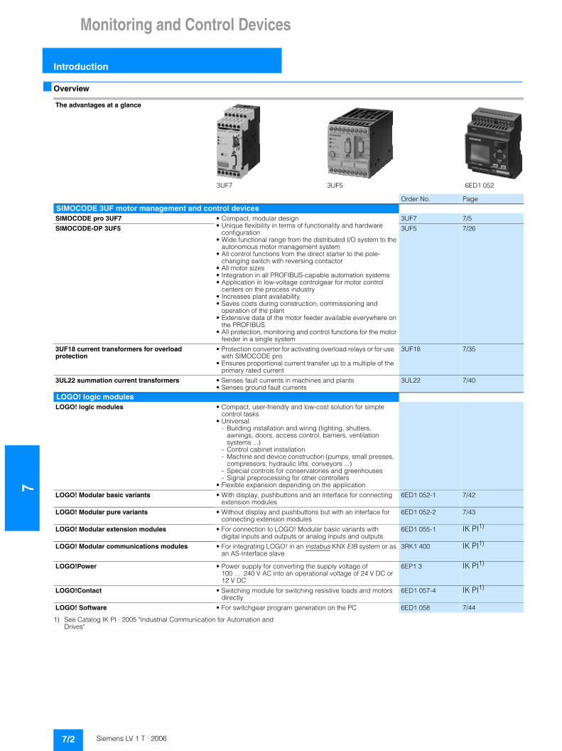
Order No. PageSIMOCODE 3UF motor management and control devicesSIMOCODE pro 3UF7 • Compact, modular design
• Unique flexibility in terms of functionality and hardware configuration
• Wide functional range from the distributed I/O system to the autonomous motor management system
• All control functions from the direct starter to the pole-changing switch with reversing contactor
• All motor sizes• Integration in all PROFIBUS-capable automation systems• Application in low-voltage controlgear for motor control
centers on the process industry• Increases plant availability• Saves costs during construction, commissioning and
operation of the plant• Extensive data of the motor feeder available everywhere on
the PROFIBUS• All protection, monitoring and control functions for the motor
feeder in a single system
3UF7 7/5
SIMOCODE-DP 3UF5 3UF5 7/26
3UF18 current transformers for overload protection
• Protection converter for activating overload relays or for use with SIMOCODE pro
• Ensures proportional current transfer up to a multiple of the primary rated current
3UF18 7/35
3UL22 summation current transformers • Senses fault currents in machines and plants• Senses ground fault currents
3UL22 7/40
LOGO! logic modulesLOGO! logic modules • Compact, user-friendly and low-cost solution for simple
control tasks• Universal:
- Building installation and wiring (lighting, shutters, awnings, doors, access control, barriers, ventilation systems ...)
- Control cabinet installation- Machine and device construction (pumps, small presses,
compressors, hydraulic lifts, conveyors ...) - Special controls for conservatories and greenhouses- Signal preprocessing for other controllers
• Flexible expansion depending on the application
LOGO! Modular basic variants • With display, pushbuttons and an interface for connecting extension modules
6ED1 052-1 7/42
LOGO! Modular pure variants • Without display and pushbuttons but with an interface for connecting extension modules
6ED1 052-2 7/43
LOGO! Modular extension modules • For connection to LOGO! Modular basic variants with digital inputs and outputs or analog inputs and outputs
6ED1 055-1 IK PI1)
LOGO! Modular communications modules • For integrating LOGO! in an instabus KNX EIB system or as an AS-Interface slave
3RK1 400 IK PI1)
LOGO!Power • Power supply for converting the supply voltage of 100 ... 240 V AC into an operational voltage of 24 V DC or 12 V DC
6EP1 3 IK PI1)
LOGO!Contact • Switching module for switching resistive loads and motors directly
6ED1 057-4 IK PI1)
LOGO! Software • For switchgear program generation on the PC 6ED1 058 7/44
3UF7 3UF5 6ED1 052
7/2 Siemens LV 1 T · 2006
Monitoring and Control Devices
7
Introduction
The advantages at a glance
Order No. Page
3RP, 7PV timing relays3RP15 timing relays in industrial enclosure, 22.5 mm
• Low-cost solution with monofunctions such as response delay, off-delay, clock-pulse, wye-delta function and multifunction
3RP15 7/49
• Wide-range voltage designs
3RP20 timing relays, 45 mm • The solution for small mounting depths 3RP20 7/55• The low mounting height reduces the tier spacing
7PV timing relays for panel mounting • Digital variant 7PV 7/58
3RT19 timing relays for mounting onto contactors • Saves space because the relay is mounted onto the contactor
3RT19 7/60
• Wiring advantages thanks to direct contacting with contactor
3UG monitoring relays for electrical and additional measurementsLine monitoring
Phase sequence • Low-cost solution for monitoring the phase sequence 3UG45 11 7/63
Phase sequence, phase failure, phase unbalance • Wide voltage range from 160 ... 690 V 3UG45 12 7/63
Phase sequence, phase failure, phase unbalance and undervoltage
• Analog adjustable• Wide voltage range from 160 ... 690 V
3UG45 13 7/64
• Digitally adjustable with LCD display for indication of ACTUAL value and device status
• Wide voltage range from 160 ... 690 V
3UG46 14 7/64
Phase sequence, phase failure, phase unbalance and overvoltage and undervoltage
• Digitally adjustable with LCD display for indication of ACTUAL value and device status
• Wide voltage range from 160 ... 690 V
3UG46 15 7/65
Phase sequence, phase and N conductor failure, phase unbalance, overvoltage and undervoltage
3UG46 16 7/65
Automatic correction of the direction of rotation in case of wrong phase sequence, phase failure, phase unbalance, overvoltage and undervoltage
3UG46 17 7/65
Automatic correction of the direction of rotation in case of wrong phase sequence, phase and N conductor failure, phase unbalance, overvoltage and undervoltage
3UG46 18 7/65
Voltage monitoring
Voltage monitoring with internal power supply for overvoltage and undervoltage
• Digitally adjustable with LCD display for indication of ACTUAL value and device status
• Wide measuring ranges• Variant for wide voltage range
3UG46 33 7/69
Voltage monitoring with auxiliary voltage for overvoltage and undervoltage
3UG46 31/32 7/70
Current monitoring
Current monitoring with auxiliary voltage for overvoltage and undervoltage
• Digitally adjustable with LCD display for indication of ACTUAL value and device status
• Wide measuring ranges• Variant for wide voltage range
3UG46 21/22 7/73
Power factor monitoring (motor load monitoring)
Monitoring relay for overshoot and undershoot monitoring with internal power supply (window monitoring)
• Upper and lower threshold value can be adjusted separately
3UG30 14 7/76
Insulation resistance
Monitoring of the insulation resistance for ungrounded AC or DC networks from 10 ... 110 k�
• Test button 3UG30 81,3UG30 82
7/78• With or without memory• Switchable measuring range
Level monitoring
Fill level and resistance • As single-step or two-step controls for inlet or outlet monitoring of conducting liquids or as resistance threshold switch
3UG35 01 7/82
• Variable, wide range from 5 ... 100 k�• UNDER/OVER adjustable
Speed monitoring
Underspeed monitoring • Together with a sensor for monitoring continuous pulses 3UG30 51 7/85• With or without memory• Adjustable ON delay• 1, 2 and 3 changeover contacts• Hard gold-plated contacts in combination and wide voltage
range versions
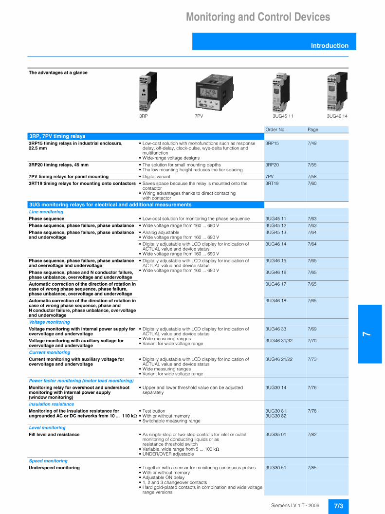
3RP 7PV 3UG45 11 3UG46 14
7/3Siemens LV 1 T · 2006
7Monitoring and Control Devices
Introduction
The advantages at a glance
Order No. Page
3RS10, 3RS11, 3RS20 temperature monitoring relaysFor monitoring the temperatures of solids, liquids, and gases
Relays, analog adjustable • Separate versions for overshoot and undershoot 3RS10,3RS11
7/90• For simple monitoring tasks• For PT100 or thermoelements J and K• Variable hysteresis
Relays, digitally adjustable acc. to DIN 3440 • For two-step or three-step controls 3RS10,3RS11, 3RS20
7/92• For monitoring heat generation plants• For PT100/1000, KTY83/84, NTC or thermoelements
type J, K, T, E, N, R, S, B
Relays, digitally adjustable for up to 3 sensors • For simultaneously monitoring several sensors 3RS10 7/94• Especially suited for monitoring motor winding temperatures• For PT100/1000, KTY83/84, NTC
3RN1 thermistor motor protectionFor PTC sensors • Relays for monitoring motor winding temperatures with
type A PTC sensors3RN1 7/96
• Integrated with ATEX license• Closed-circuit principle• Depending on the version: With short-circuit and open-circuit
detection, zero voltage safety, manual/auto/remote RESET, 1 CO, 1 NO + 1 NC, 2 CO, 1 NO + 1 CO or 2 CO hard gold-plated
3TK28 safety relaysWith electronic enabling circuits • Permanent function checking
• No wear because switched electronically• High switching frequency• Long electrical endurance• Evaluation of solid-state sensors• Sensor lead up to max. 2000 m• Cascading possible• Insensitive to vibrations and dirt• Compact design, low weight• Approved for the world market
3TK28 4 7/102
With relay enabling circuits • Compact design• Floating safe outputs• Also suitable for press and punch controls• Can be used up to an ambient temperature of max. 70 °C
3TK28 2, 3TK28 3 7/105
With contactor relay enabling circuits • Floating enabling circuits• AC-15/DC-13 switching capacity• Safe isolation• Long mechanical and electrical endurance• Certified as a complete unit• Fault minimization and cost reduction through factory wiring• Low installation costs
3TK28 5 7/108
3RA71 load feeders with integrated safety functions
• Available in fused or fuseless configuration• Floating enabling circuits• AC-1/AC-3 switching capacity• Certified as a complete unit• Long mechanical and electrical endurance• Rated operational voltage up to 690 V• Safe isolation
3TK28 5 Ch. 6
3RS17 interface convertersConverters for standard signals and non-standard variables
• All terminals protected against polarity reversing and overvoltage up to 30 V
• For electrical isolation and conversion of analog signals• Short-circuit resistant outputs• From 6.2 mm width• Switchable multi-range converters• Variants with manual/automatic switch for setpoint input or
for the conversion of analog variables into frequency
3RS17 7/112
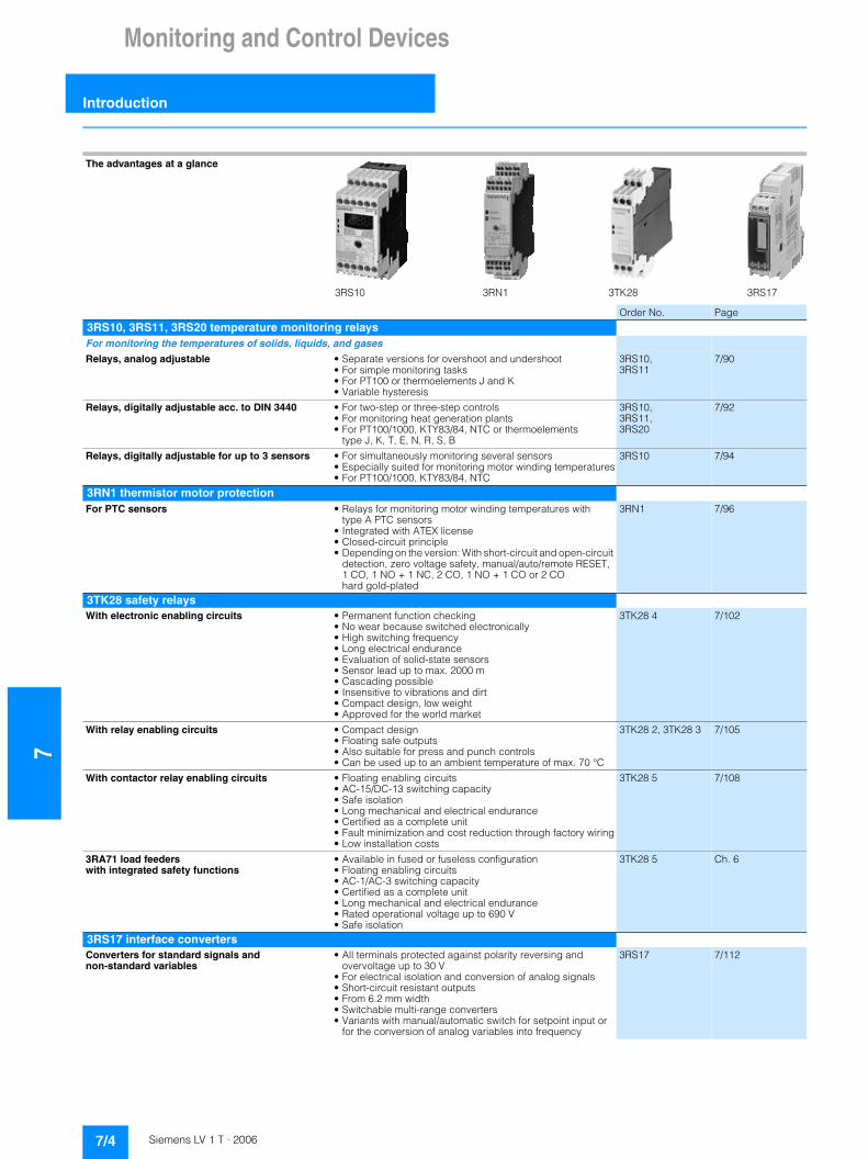
3RS10 3RN1 3TK28 3RS17
7/4 Siemens LV 1 T · 2006

SIMOCODE 3UF Motor Management and Control Devices
7
SIMOCODE pro 3UF7motor management and control devices
■ Overview
SIMOCODE pro is a flexible, modular motor management sys-tem for motors with constant speeds in the low-voltage perfor-mance range. It optimizes the connection between I&C and motor feeder, increases plant availability and allows significant savings to be made for startup, operation and maintenance of a system.
When SIMOCODE pro is installed in the low-voltage switchgear cabinet, it is the intelligent interface between the higher-level automation system and the motor feeder and includes the following:• Multifunctional, solid-state full motor protection which is
independent of the automation system• Flexible software instead of hardware for the motor control• Detailed operational, service and diagnostics data• Open communication through PROFIBUS DP, the standard for
fieldbus systems
■ Design
General
SIMOCODE pro is a modularly constructed motor management system which is subdivided into two device series with different functional scopes:• SIMOCODE pro C • SIMOCODE pro V
Both series (systems) are made up of different hardware components (modules):
Per feeder each system always comprises one basic unit and one separate current measuring module. The two modules are connected together electrically through the system interface with a connection cable and can be mounted mechanically connected as a unit (one behind the other) or separately (side by side). The motor current to be monitored is decisive only for the choice of current measuring module.
An operator panel for mounting in the control cabinet door is optionally connectable through a second system interface on the basic unit. Both the current measurement module and the operator panel are electrically supplied by the basic unit through the connection cable. More inputs, outputs and functions can be added to basic unit 2 (SIMOCODE pro V) by means of optional expansion modules, thus supplementing the inputs and outputs already existing on the basic unit.
All modules are connected together by connection cables. The connection cables are available in various lengths. The maximum distance between the modules (e.g. between the basic unit and the current measurement module) must not exceed 2 m. The total length of all the connection cables in a single system must not be more than 3 m.
SIMOCODE pro designed for mixed operation
Depending on functional requirements, the two systems can be used simultaneously without any problems and without any addi-tional outlay in a low-voltage system. SIMOCODE pro C is fully upward-compatible to SIMOCODE pro V. The same compo-nents are used. The parameterization of SIMOCODE pro C can be transferred without any problems. Both systems have the same removable terminals and the same terminal designations.
System SIMOCODE pro C SIMOCODE pro V
Modules • Basic unit 1 • Basic unit 2• Current measuring module • Current measuring module or
current/voltage measuring voltage
• Operator panel (optional) • Operator panel (optional)• Expansion modules
(optional)
7/5Siemens LV 1 T · 2006

7SIMOCODE 3UF Motor Management and Control Devices
SIMOCODE pro 3UF7 motor management and control devices
SIMOCODE pro C, basic unit 1
The compact system for • Direct-on-line and reversing starters• Actuation of a circuit-breaker (MCCB)with up to 4 binary inputs, up to 3 monostable relay outputs and one thermistor connection (binary PTC)
The basic unit 1 is available in two different variants for the following supply voltages:• 24 V DC• 110 ... 240 V AC/DC
SIMOCODE pro C, basic unit 1
Inputs:• 4 binary inputs, with internal supply from 24 V DC
Outputs:• 3 (2+1) monostable relay outputs
Thermistor connection for binary PTC
PROFIBUS interface:• 9-pole SUB-D or • Terminal connection
Connection of the supply voltage:• 24 V DC or• 110 ... 240 V AC/DC
Test/Reset button
3 LEDs
2 system interfaces for connection of• a current measuring module and• an operator panel
Basic unit 1 is suitable for standard rail mounting or, with additional push-in lugs, for fixing to a mounting plate.
SIMOCODE pro V, basic unit 2
The variable system which offers all SIMOCODE pro C functions plus many additional functions. Basic unit 2 supports the following control functions:• Direct-on-line and reversing starters• Star/delta starters, also with direction reversal• Two speeds, motors with separate windings (pole-changing
switch); also with direction reversal• Two speeds, motors with separate Dahlander windings (also
with direction reversal)• Slide control• Solenoid valve actuation• Actuation of a circuit-breaker (MCCB)• Soft starter actuation (also with direction reversal)
Basic unit 2 has 4 binary inputs, 3 monostable relay outputs and one thermistor connection (binary PTC). The type and number of inputs and outputs can be increased by means of additional expansion modules.
Basic unit 2 is available in two different variants for the following supply voltages:• 24 V DC• 110 ... 240 V AC/DC
SIMOCODE pro V, basic unit 2
Inputs:• 4 binary inputs, with internal supply from 24 V DC
Outputs:• 3 (2+1) monostable relay outputs
Thermistor connection for binary PTC
PROFIBUS interface:• 9-pole SUB-D or • Terminal connection
Connection of the supply voltage:• 24 V DC or• 110 ... 240 V AC/DC
Test/Reset button
3 LEDs
7/6 Siemens LV 1 T · 2006
SIMOCODE 3UF Motor Management and Control Devices
7
SIMOCODE pro 3UF7motor management and control devices
2 system interfaces for connection of• a current measuring module or current/voltage measuring
module• expansion modules and• an operator panel
Basic unit 2 is suitable for standard rail mounting or, with additional push-in lugs, for fixing to a mounting plate.
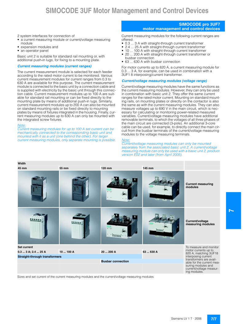
Current measuring modules (current ranges)
The current measurement module is selected for each feeder according to the rated motor current to be monitored. Various current measurement modules for current ranges from 0.3 to 630 A are available for this purpose. The current measurement module is connected to the basic unit by a connection cable and is supplied with electricity by the basic unit through this connec-tion cable. Current measurement modules up to 100 A are suit-able for standard rail mounting or can be fixed directly to the mounting plate by means of additional push-in lugs. Similarly, current measurement modules up to 200 A can also be mounted on standard mounting rails or be fixed directly to mounting plates by means of fixtures integrated in the housing. Finally, cur-rent measuring modules up to 630 A can only be mounted with the integrated screw fixtures.
Note: Current measuring modules for up to 100 A set current can be mechanically connected to the corresponding basic unit and mounted with it as a unit (one behind the other). For larger current measuring modules, only separate mounting is possible.
Current measuring modules for the following current ranges are offered:• 0.3 ... 3 A with straight-through current transformer• 2.4 ... 25 A with straight-through current transformer• 10 ... 100 A with straight-through current transformer• 20 ... 200 A with straight-through current transformer or
busbar connection• 63 ... 630 A with busbar connection
For motor currents up to 820 A, a current measuring module for 0.3 ... 3 A, for example, can be used in combination with a3UF1 8 interposing/current transformer.
Current/voltage measuring modules (voltage range)
Current/voltage measuring modules have the same functions as the current measuring modules. However, they can only be used in combination with basic unit 2. They offer the same current ranges for the rated motor current. Mounting on standard mount-ing rails, on mounting plates or directly on the contactor is also the same as with the current measuring modules. They can also measure voltages up to 690 V in the main circuit, which is nec-essary for calculating or monitoring power-related measured variables. Current/voltage measuring modules have additional removable terminals, to which the voltages of all three phases of the main circuit are connected (3-pole). An additional 3-core cable can be used, for example, to directly connect the main cir-cuit from the busbar terminals of the current/voltage measuring modules to the voltage measuring terminals.
Note: Current/voltage measuring modules can only be mounted separately from the associated basic unit 2. A current/voltage measuring module can only be used with a basic unit 2, product version E02 and later (from April 2005).
Sizes and set current of the current measuring modules and the current/voltage measuring modules
Width
45 mm 55 mm 120 mm 145 mm
Current measuring modules
Current/voltage measuring modules
Set current To measure and monitor motor currents up to 820 A, matching 3UF18 interposing current transformers are avail-able for the current mea-suring modules and current/voltage measur-ing modules.
0.3 ... 3 A; 2.4 ... 25 A 10 ... 100 A 20 ... 200 A 63 ... 630 A
Straight-through transformers
Busbar connection
7/7Siemens LV 1 T · 2006
7SIMOCODE 3UF Motor Management and Control Devices
SIMOCODE pro 3UF7 motor management and control devices
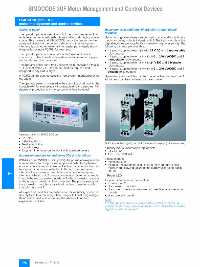
Operator panel
The operator panel is used to control the motor feeder and can replace all conventional pushbuttons and indicator lights to save space. This means that SIMOCODE pro or the feeder can be operated directly at the control cabinet and that the system interface is connected externally for easier parameterization or diagnostics using a PC/PG, for example.
The operator panel is connected to the basic unit over a connection cable from its rear system interface and is supplied electrically from the basic unit.
The operator panel has 5 freely assignable buttons and a total of 10 LEDs, of which 7 LEDs can be used as required and assigned to any status signal.
A PC/PG can be connected to the front system interface over the PC cable.
The operator panel is mounted in the control cabinet door or the front plate of, for example, a withdrawable unit and satisfies IP54 degree of protection with the system interface covered.
Operator panel for SIMOCODE pro
• 10 LEDs• Labeling strips• Test/reset button• 4 control keys• 2 system interfaces on the front with interface covers
Expansion modules for additional I/Os and functions
With basic unit 2 (SIMOCODE pro V), it is possible to expand the number and type of inputs and outputs in order to implement additional functions, for example. Each expansion module has two system interfaces on the front. Through the one system interface the expansion module is connected to the system interface of basic unit 2 using a connection cable, for example; through the second system interface, further expansion modules or the operator panel can be connected. The power supply for the expansion modules is provided by the connection cable through basic unit 2.
All expansion modules are suitable for rail mounting or can be directly fixed to a mounting plate using additional plug-in lugs. Basic unit 2 can be extended on the whole with up to 5 expansion modules.
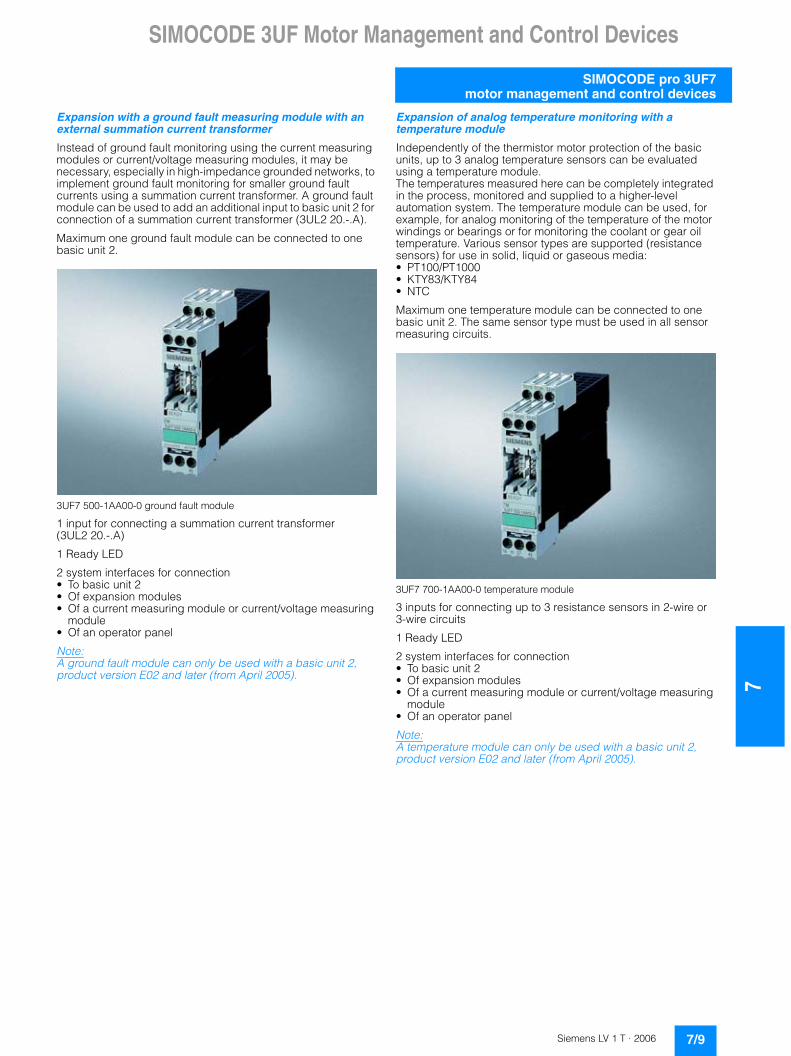
Expansion with additional binary I/Os through digital modules
Up to two digital modules can be used to add additional binary inputs and relay outputs to basic unit 2. The input circuits of the digital modules are supplied from an external power supply. The following variants are available:• 4 inputs, supplied externally with 24 V DC and 2 monostable
relay outputs• 4 inputs, supplied externally with 110 ... 240 V AC/DC and 2
monostable relay outputs• 4 inputs, supplied externally with 24 V DC and 2 bistable
relay outputs• 4 inputs, supplied externally with 110 ... 240 V AC/DC and 2
bistable relay outputs
Up to two digital modules can be connected to one basic unit 2. All variants can be combined with each other.
3UF7 300-1AB00-0 (left) and 3UF7 300-1AU00-0 (right) digital modules
4 binary inputs, externally supplied with• 24 V DC or • 110 ... 240 V AC/DC
2 relay outputs,• monostable or• bistable (the switching status of the relay outputs is also
maintained following failure of the supply voltage on basic unit 2)
1 Ready LED
2 system interfaces for connection• to basic unit 2• of expansion modules• of a current measuring module or current/voltage measuring
module• of an operator panel
Note: For the implementation of some motor control functions, in addition to the relay outputs on basic unit 2, at least one further digital module is required.
7/8 Siemens LV 1 T · 2006
SIMOCODE 3UF Motor Management and Control Devices
7
SIMOCODE pro 3UF7motor management and control devices
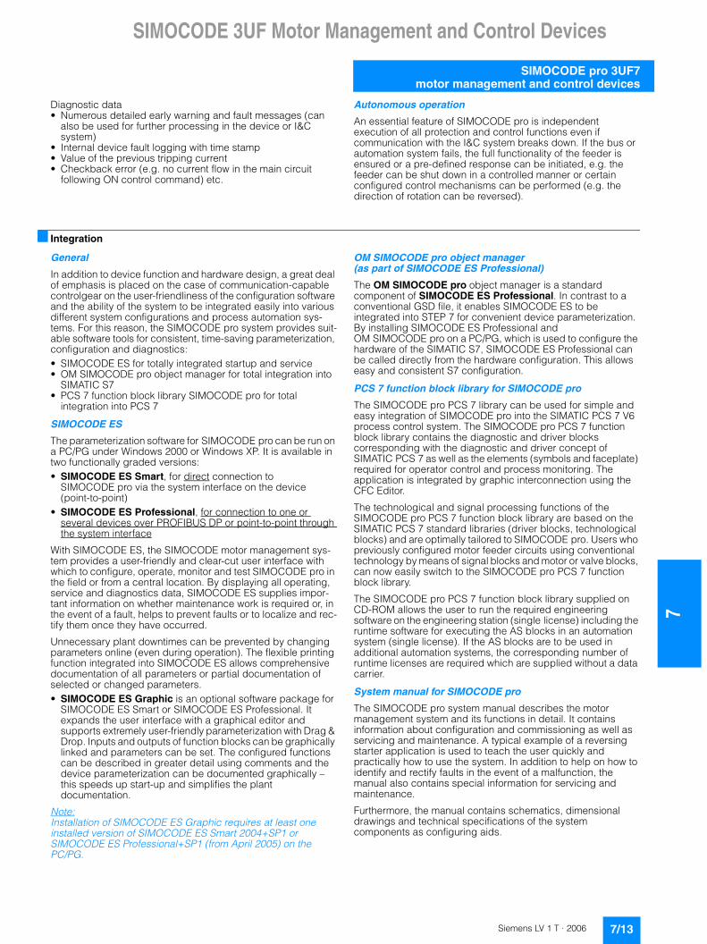
Expansion with a ground fault measuring module with an external summation current transformer
Instead of ground fault monitoring using the current measuring modules or current/voltage measuring modules, it may be necessary, especially in high-impedance grounded networks, to implement ground fault monitoring for smaller ground fault currents using a summation current transformer. A ground fault module can be used to add an additional input to basic unit 2 for connection of a summation current transformer (3UL2 20.-.A).
Maximum one ground fault module can be connected to one basic unit 2.
3UF7 500-1AA00-0 ground fault module
1 input for connecting a summation current transformer (3UL2 20.-.A)
1 Ready LED
2 system interfaces for connection • To basic unit 2• Of expansion modules• Of a current measuring module or current/voltage measuring
module• Of an operator panel
Note: A ground fault module can only be used with a basic unit 2, product version E02 and later (from April 2005).
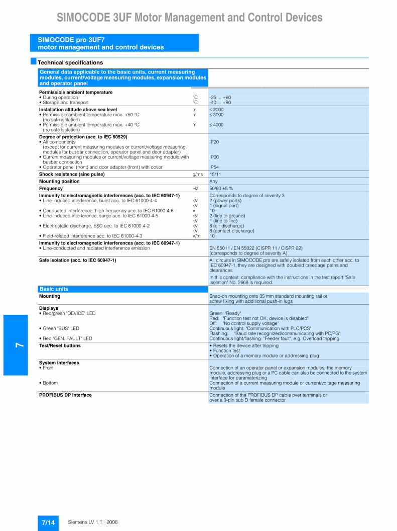
Expansion of analog temperature monitoring with a temperature module
Independently of the thermistor motor protection of the basic units, up to 3 analog temperature sensors can be evaluated using a temperature module. The temperatures measured here can be completely integrated in the process, monitored and supplied to a higher-level automation system. The temperature module can be used, for example, for analog monitoring of the temperature of the motor windings or bearings or for monitoring the coolant or gear oil temperature. Various sensor types are supported (resistance sensors) for use in solid, liquid or gaseous media:• PT100/PT1000• KTY83/KTY84• NTC
Maximum one temperature module can be connected to one basic unit 2. The same sensor type must be used in all sensor measuring circuits.
3UF7 700-1AA00-0 temperature module
3 inputs for connecting up to 3 resistance sensors in 2-wire or 3-wire circuits
1 Ready LED
2 system interfaces for connection • To basic unit 2• Of expansion modules• Of a current measuring module or current/voltage measuring
module• Of an operator panel
Note: A temperature module can only be used with a basic unit 2, product version E02 and later (from April 2005).
7/9Siemens LV 1 T · 2006

7SIMOCODE 3UF Motor Management and Control Devices
SIMOCODE pro 3UF7 motor management and control devices
Expansion with additional inputs/outputs by means of an analog module
Basic unit 2 can be optionally expanded with analog inputs and outputs (0/4 ... 20 mA) by means of the analog module. It is then possible to measure and monitor any process variable that can be mapped on a 0/4 ... 20 mA signal. Typical applications are, for example, level monitoring for the implementation of dry run-ning protection for pumps or monitoring the degree of pollution of a filter using a differential pressure transducer. In this case the automation system has free access to the measured process variables. The analog output can be used, for example, to visu-alize process variables on a pointer instrument. The automation system also has free access to the output.
Maximum one analog module can be connected to one basic unit 2. Both inputs are set to a measuring range of either 0 ... 20 mA or 4 ... 20 mA.
3UF7 400-1AA00-0 analog module
Inputs:• 2 inputs for measuring 0/4 ... 20 mA signals
Outputs:• 1 output to output a 0/4 ... 20 mA signal
1 Ready LED
2 system interfaces for connection • To basic unit 2• Of expansion modules• Of a current measuring module or current/voltage measuring
module• Of an operator panel
Note: An analog module can only be used with a basic unit 2, product version E02 and later (from April 2005).
Safe isolation
All circuits in SIMOCODE pro are safely isolated from each other in according to IEC 60947-1. That is, they are designed with double creepage and air distances. In the event of a fault, therefore, no parasitic voltages can be formed in neighboring circuits. The instructions of test report No. 2668 must be complied with.
EEx e and EEx d types of protection
The overload protection and the thermistor motor protection of the SIMOCODE pro system comply with the requirements for overload protection of explosion-protected motors to the degree of protection:• EEx d "flameproof enclosure" e.g. according to EN 50018 or
EN 60079-1• EEx e "increased safety" e.g. according to EN 50019 or
EN 60079-7
When using SIMOCODE pro devices with a 24 V DC control voltage, electrical isolation must be ensured using a battery or a safety transformer according to EN 61558-2-6.
EC type test certificate: BVS 04 ATEX F 003 Test log: BVS PP 05.2029 EG.
7/10 Siemens LV 1 T · 2006

SIMOCODE 3UF Motor Management and Control Devices
7
SIMOCODE pro 3UF7motor management and control devices
■ Function
Multifunctional, solid-state full motor protection
Current-dependent electronic overload protection with adjustable tripping characteristics (Classes 5, 10, 15, 20, 25, 30, 35 and 40)• SIMOCODE pro protects three-phase or AC motors according
to IEC 60947-4-1 requirements. The trip class can be adjusted in eight steps from Class 5 to Class 40. In this way, the break time can be adapted very accurately to the load torque which allows the motor to be utilized more effectively. In addition, the time until the overload tripping operation is performed is calculated and can be made available to the I&C system. After an overload tripping operation, the remaining cooling time can be displayed (characteristic curves for 2-pole and 3-pole loading in SIMOCODE pro System Manual).
Phase failure/unbalance protection• The level of the phase unbalance can be monitored and trans-
mitted to the I&C system. If a specified limit value is violated, a defined and delayable response can be initiated. If the phase unbalance is larger than 50 %, the tripping time is also automatically reduced according to the overload characteris-tic since the heat generation of the motors increases in unbal-anced conditions.
Stall protection• If the motor current rises above an adjustable blocking
threshold (current threshold), a defined and delayable response can be configured for SIMOCODE pro. In this case, for example, the motor can be shut down independent of the overload protection. The blocking protection is only enabled after the configured class time has elapsed and avoids unnecessarily high thermal and mechanical loads as well as wear of the motor.
Thermistor motor protection• This protection function is based on direct temperature
measurements by means of temperature sensors in the stator windings or in the enclosure of the motor. These protective functions should be used, in particular, in motors with high operating frequencies, heavy-duty starting, intermittent and/or braking operation, but also in the case of speeds lower than the rated speed. SIMOCODE pro supports connection and evaluation of several PTC sensors connected in series on the basic unit. In addition, the sensor measuring circuit can be monitored for short-circuits and wire breakages. If the temperature of the motor increases beyond a defined limit or if there is a fault in the sensor measuring circuit, a defined response can be configured.
Ground-fault monitoring (internally) with a current measuring module or current/voltage measuring module• SIMOCODE pro acquires and monitors all three phase
currents. With vector addition of the phase currents, the motor feeder can be monitored for possible fault currents or ground faults with the help of internal calculations. Internal earth fault monitoring is only available for motors with three-phase connections in directly grounded networks or in networks grounded with low impedance. The response of SIMOCODE pro when a ground fault is detected can be parameterized and delayed as required.
Ground-fault monitoring (external) with summation current transformer1)2)
• External ground-fault monitoring is normally implemented for networks that are grounded with high impedance. Using an additional summation current transformer (3UL2 20.-.A), even extremely low ground-fault currents can be measured. The response of SIMOCODE pro when a ground fault is detected can be parameterized and delayed as required. Fault current measurement is performed for each summation current transformer for the following fault currents: 0.3/0.5/1 A
Monitoring of adjustable limit values for the motor current• Current limit value monitoring is used for process monitoring
independent of overload protection. Violation of a current limit value below the overload threshold can be an indication for a dirty filter in a pump or for an increasingly sluggish motor bearing, for example. Violation of the lower current limit value can be a first indication of a worn drive belt. SIMOCODE pro supports two-step monitoring of the motor current for freely selectable upper and lower current limit values. The response of SIMOCODE pro can be freely configured and delayed if it reaches an alarm or tripping threshold.
Voltage monitoring3) • By measuring the voltage directly at the circuit-breaker or at
the fuses in the main circuit, even when the motor is deactivated, SIMOCODE pro can also obtain information about the reclosing capability of the feeder and signal it if required.
• SIMOCODE pro supports two-stage undervoltage monitoring for freely selectable limit values. The response of SIMOCODE pro can be freely configured and delayed if it reaches an alarm or tripping threshold.
Monitoring the active power3)
• The active power characteristic of a motor provides an accurate statement of the actual loading over the complete range. Excessive loading will cause increased wear in the motor and can result in early failure. Insufficient active power can be an indication of, for example, motor idling.
• SIMOCODE pro supports two-step monitoring of the active power for freely selectable upper and lower current limit values. The response of SIMOCODE pro can be freely configured and delayed if it reaches an alarm or tripping threshold.
Monitoring the power factor3)
• Especially in the low-end performance range of a motor, the power factor varies more than the motor current or active power. Monitoring of the power factor is therefore particularly useful for distinguishing between motor idling and fault events such as a tear in a drive belt or a crack in a drive shaft.
• SIMOCODE pro supports two-stage monitoring of power factor undershoot for freely selectable limit values. The response of SIMOCODE pro can be freely configured and delayed if it reaches an alarm or tripping threshold.
Temperature monitoring1)4)
• The temperature can be monitored, for example, in the motor windings or at the bearings through up to three resistance sensors connected to the temperature module.
• SIMOCODE pro supports two-stage monitoring of overheating for freely selectable limit values. The response of SIMOCODE pro can be freely configured and delayed if it reaches an alarm or tripping threshold. Temperature monitoring is always performed with reference to the highest temperature of all sensor measuring circuits used.
1) Using basic unit 2.2) An additional ground-fault module with a 3UL22 summation current
transformer is required.3) Using basic unit 2 with current/voltage measuring module.4) An additional temperature module is required.
7/11Siemens LV 1 T · 2006

7SIMOCODE 3UF Motor Management and Control Devices
SIMOCODE pro 3UF7 motor management and control devices
Monitoring additional process variables over analog inputs (0/4 ... 20 mA)1)2)
• The analog module enables SIMOCODE pro to measure additional process variables and monitor them. A pump can, for example, be protected against dry running in this manner with level monitoring or the degree of pollution of a filter can be measured using a differential pressure transducer. When a specified level is undershot, the pump can be deactivated and when a specified differential pressure is overshot, the filter can be cleaned.
• SIMOCODE pro supports two-step monitoring of the corre-sponding process variable for freely selectable upper and lower current limit values. The response of SIMOCODE pro can be freely configured and delayed if it reaches an alarm or tripping threshold.
Phase sequence detection3) • By detecting the phase sequence, SIMOCODE pro is able to
make a statement about the direction of rotation of a motor. If the direction is incorrect, this can be reported or it can result in immediate shutdown of the affected motor.
Monitoring of operating hours, downtime and number of starts• In order to prevent plant downtime caused by motor failure
due to excessive motor operating times (wear) or excessive motor downtimes, SIMOCODE pro can monitor the operating hours and downtime of a motor. When an adjustable limit value is violated, a message or alarm can be generated which can indicate that the corresponding motor must be serviced or replaced. After the motor has been replaced, the operating hours and downtimes can be reset, for example.
• To avoid excessive thermal loads and early wear of the motor, it is possible to limit the number of motor startups for a specifiable period. Alarms can indicate that only a small number of possible starts remain.
Flexible motor control implemented with software
Many typical motor control functions have been predefined in SIMOCODE pro and are available for use:• Direct-on-line and reversing starters• Wye-delta starters (also with direction reversal)1)
• Two speeds, motors with separate windings (pole-changing switch); also with direction reversal1)
• Two speeds, motors with separate Dahlander windings (also with direction reversal)1)
• Slide control1)
• Solenoid valve actuation1)
• Actuation of a circuit-breaker (MCCB)• Actuation of a 3RW soft starter also with direction reversal1)
These control programs already include all the software interlocks and logic operations required for operation of the required motor functions.
It is also monitored whether the current checkback of the motor feeder corresponds with the control command. If not, SIMOCODE pro opens the motor contactor and generates an alarm indication.
Depending on the application, motor control can be switched over or carried out simultaneously from several control stations, e.g.:• From the I&C system through PROFIBUS DP• From a PC/PG through PROFIBUS DP• From the control cabinet door through the operator panel• From a PC/PG on the system interface through
SIMOCODE pro• From a local control station on the motor. In this case, the
buttons, switches and indicator lights are connected to the inputs and outputs of SIMOCODE pro.
Regardless of whether a control command is sent to SIMOCODE pro via PROFIBUS DP using the operator module or via the buttons connected to the binary SIMOCODE pro inputs, SIMOCODE pro can execute these control commands simultaneously or in accordance with the enabled commands defined during configuration.
These predefined control functions can also be flexibly adapted to each customized configuration of a motor feeder by means of freely configurable logic modules (truth tables, counters, timers, edge evaluation etc.).
In addition, special standard functions are stored in SIMOCODE pro which can also be used to extend the protection and control functions, e.g.:• Power failure monitoring1) for automatic, time-staggered
restart of motors following a network failure e.g. with the help of a separate voltage relay (voltage controller).
• Fault signaling modules for external faults with or without manual or automatic acknowledgement for generating internal messages or for tripping SIMOCODE pro in response to freely definable events (e.g. overspeed monitor has been activated). Designations/names can also be assigned to the external faults which are stored in the device and which are therefore also available to the I&C system.
• Emergency start function and reset of the thermal memory of SIMOCODE pro after tripping, i.e. immediate restart is possible (important, for example, for pumps used to extinguish fires).
• Test function for the load feeder circuit when the main control switch is open to test the control circuit while the main circuit is de-energized.
Detailed operational, service and diagnostics data
SIMOCODE pro provides a variety of operating, service and diagnostic data, such as:
Operating data• The switching state of the motor (On, Off, clockwise, counter-
clockwise, fast, slow) is derived from the current flow in the main circuit, so checkbacks are not required through auxiliary contacts from circuit-breakers and contactors
• Current in phase 1, 2, 3 and maximum current in % of the set current
• Voltage in phases 1, 2, 3 in V3) • Active power in W3) • Apparent power in VA3) • Power factor in %3) • Phase unbalance in %• Phase sequence3) • Temperature in sensor circuits 1, 2, 3 and maximum
temperature in °C1)4) • Current values of the analog signals1)2) • Time until tripping in sec.• Temperature rise for motor model in %• Remaining cooling time of the motor in sec. etc.
Service data• Motor operating hours (can be reset)• Motor stop times (can be reset)• Number of motor starts (can be reset)• Number of remaining permissible motor starts• Number of overload trips (can be reset)• Internal comments, stored in the device for each feeder,
e.g. notes for maintenance events etc.
1) Using basic unit 2.
2) An additional analog module is required.
3) Using basic unit 2 with current/voltage measuring module.
4) An additional temperature module is required.
7/12 Siemens LV 1 T · 2006
SIMOCODE 3UF Motor Management and Control Devices
7
SIMOCODE pro 3UF7motor management and control devices
Diagnostic data• Numerous detailed early warning and fault messages (can
also be used for further processing in the device or I&C system)
• Internal device fault logging with time stamp• Value of the previous tripping current• Checkback error (e.g. no current flow in the main circuit
following ON control command) etc.
Autonomous operation
An essential feature of SIMOCODE pro is independent execution of all protection and control functions even if communication with the I&C system breaks down. If the bus or automation system fails, the full functionality of the feeder is ensured or a pre-defined response can be initiated, e.g. the feeder can be shut down in a controlled manner or certain configured control mechanisms can be performed (e.g. the direction of rotation can be reversed).
■ Integration
General
In addition to device function and hardware design, a great deal of emphasis is placed on the case of communication-capable controlgear on the user-friendliness of the configuration software and the ability of the system to be integrated easily into various different system configurations and process automation sys-tems. For this reason, the SIMOCODE pro system provides suit-able software tools for consistent, time-saving parameterization, configuration and diagnostics:• SIMOCODE ES for totally integrated startup and service• OM SIMOCODE pro object manager for total integration into
SIMATIC S7 • PCS 7 function block library SIMOCODE pro for total
integration into PCS 7
SIMOCODE ES
The parameterization software for SIMOCODE pro can be run on a PC/PG under Windows 2000 or Windows XP. It is available in two functionally graded versions: • SIMOCODE ES Smart, for direct connection to
SIMOCODE pro via the system interface on the device(point-to-point)
• SIMOCODE ES Professional, for connection to one or several devices over PROFIBUS DP or point-to-point through the system interface
With SIMOCODE ES, the SIMOCODE motor management sys-tem provides a user-friendly and clear-cut user interface with which to configure, operate, monitor and test SIMOCODE pro in the field or from a central location. By displaying all operating, service and diagnostics data, SIMOCODE ES supplies impor-tant information on whether maintenance work is required or, in the event of a fault, helps to prevent faults or to localize and rec-tify them once they have occurred.
Unnecessary plant downtimes can be prevented by changing parameters online (even during operation). The flexible printing function integrated into SIMOCODE ES allows comprehensive documentation of all parameters or partial documentation of selected or changed parameters.• SIMOCODE ES Graphic is an optional software package for
SIMOCODE ES Smart or SIMOCODE ES Professional. It expands the user interface with a graphical editor and supports extremely user-friendly parameterization with Drag & Drop. Inputs and outputs of function blocks can be graphically linked and parameters can be set. The configured functions can be described in greater detail using comments and the device parameterization can be documented graphically – this speeds up start-up and simplifies the plant documentation.
Note:Installation of SIMOCODE ES Graphic requires at least one installed version of SIMOCODE ES Smart 2004+SP1 or SIMOCODE ES Professional+SP1 (from April 2005) on the PC/PG.
OM SIMOCODE pro object manager (as part of SIMOCODE ES Professional)
The OM SIMOCODE pro object manager is a standard component of SIMOCODE ES Professional. In contrast to a conventional GSD file, it enables SIMOCODE ES to be integrated into STEP 7 for convenient device parameterization. By installing SIMOCODE ES Professional and OM SIMOCODE pro on a PC/PG, which is used to configure the hardware of the SIMATIC S7, SIMOCODE ES Professional can be called directly from the hardware configuration. This allows easy and consistent S7 configuration.
PCS 7 function block library for SIMOCODE pro
The SIMOCODE pro PCS 7 library can be used for simple and easy integration of SIMOCODE pro into the SIMATIC PCS 7 V6 process control system. The SIMOCODE pro PCS 7 function block library contains the diagnostic and driver blocks corresponding with the diagnostic and driver concept of SIMATIC PCS 7 as well as the elements (symbols and faceplate) required for operator control and process monitoring. The application is integrated by graphic interconnection using the CFC Editor.
The technological and signal processing functions of the SIMOCODE pro PCS 7 function block library are based on the SIMATIC PCS 7 standard libraries (driver blocks, technological blocks) and are optimally tailored to SIMOCODE pro. Users who previously configured motor feeder circuits using conventional technology by means of signal blocks and motor or valve blocks, can now easily switch to the SIMOCODE pro PCS 7 function block library.
The SIMOCODE pro PCS 7 function block library supplied on CD-ROM allows the user to run the required engineering software on the engineering station (single license) including the runtime software for executing the AS blocks in an automation system (single license). If the AS blocks are to be used in additional automation systems, the corresponding number of runtime licenses are required which are supplied without a data carrier.
System manual for SIMOCODE pro
The SIMOCODE pro system manual describes the motor management system and its functions in detail. It contains information about configuration and commissioning as well as servicing and maintenance. A typical example of a reversing starter application is used to teach the user quickly and practically how to use the system. In addition to help on how to identify and rectify faults in the event of a malfunction, the manual also contains special information for servicing and maintenance.
Furthermore, the manual contains schematics, dimensional drawings and technical specifications of the system components as configuring aids.
7/13Siemens LV 1 T · 2006
7SIMOCODE 3UF Motor Management and Control Devices
SIMOCODE pro 3UF7 motor management and control devices
■ Technical specifications
General data applicable to the basic units, current measuring modules, current/voltage measuring modules, expansion modules and operator panel
Permissible ambient temperature• During operation °C -25 ... +60• Storage and transport °C -40 ... +80
Installation altitude above sea level m ��2000• Permissible ambient temperature max. +50 °C
(no safe isolation)m ��3000
• Permissible ambient temperature max. +40 °C(no safe isolation)
m ��4000
Degree of protection (acc. to IEC 60529)• All components
(except for current measuring modules or current/voltage measuring modules for busbar connection, operator panel and door adapter)
IP20
• Current measuring modules or current/voltage measuring module with busbar connection
IP00
• Operator panel (front) and door adapter (front) with cover IP54
Shock resistance (sine pulse) g/ms 15/11
Mounting position Any
Frequency Hz 50/60 �5 %
Immunity to electromagnetic interferences (acc. to IEC 60947-1) Corresponds to degree of severity 3• Line-induced interference, burst acc. to IEC 61000-4-4 kV
kV2 (power ports)1 (signal port)
• Conducted interference, high frequency acc. to IEC 61000-4-6 V 10• Line-induced interference, surge acc. to IEC 61000-4-5 kV
kV2 (line to ground)1 (line to line)
• Electrostatic discharge, ESD acc. to IEC 61000-4-2 kVkV
8 (air discharge)6 (contact discharge)
• Field-related interference acc. to IEC 61000-4-3 V/m 10
Immunity to electromagnetic interferences (acc. to IEC 60947-1)• Line-conducted and radiated interference emission EN 55011 / EN 55022 (CISPR 11 / CISPR 22)
(corresponds to degree of severity A)
Safe isolation (acc. to IEC 60947-1) All circuits in SIMOCODE pro are safely isolated from each other acc. to IEC 60947-1, they are designed with doubled creepage paths and clearances
In this context, compliance with the instructions in the test report "Safe Isolation" No. 2668 is required.
Basic unitsMounting Snap-on mounting onto 35 mm standard mounting rail or
screw fixing with additional push-in lugs
Displays• Red/green "DEVICE" LED Green: "Ready"
Red: "Function test not OK; device is disabled"Off: "No control supply voltage"
• Green "BUS" LED Continuous light: "Communication with PLC/PCS"Flashing: "Baud rate recognized/communicating with PC/PG"
• Red "GEN. FAULT" LED Continuous light/flashing: "Feeder fault", e.g. Overload tripping
Test/Reset buttons • Resets the device after tripping• Function test• Operation of a memory module or addressing plug
System interfaces• Front Connection of an operator panel or expansion modules; the memory
module, addressing plug or a PC cable can also be connected to the system interface for parameterizing
• Bottom Connection of a current measuring module or current/voltage measuring module
PROFIBUS DP interface Connection of the PROFIBUS DP cable over terminals orover a 9-pin sub D female connector
7/14 Siemens LV 1 T · 2006
SIMOCODE 3UF Motor Management and Control Devices
7
SIMOCODE pro 3UF7motor management and control devices
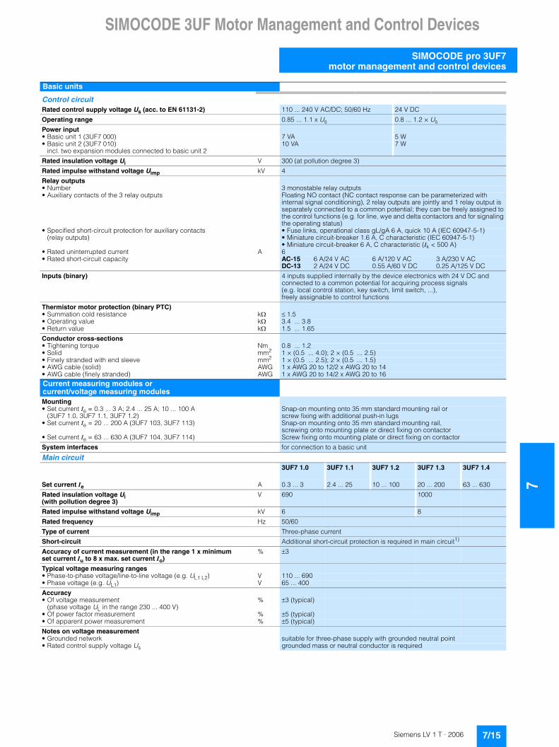
Basic units
Control circuitRated control supply voltage Us (acc. to EN 61131-2) 110 ... 240 V AC/DC; 50/60 Hz 24 V DC
Operating range 0.85 ... 1.1 x Us 0.8 ... 1.2 × Us
Power input• Basic unit 1 (3UF7 000) 7 VA 5 W• Basic unit 2 (3UF7 010)
incl. two expansion modules connected to basic unit 210 VA 7 W
Rated insulation voltage Ui V 300 (at pollution degree 3)
Rated impulse withstand voltage Uimp kV 4
Relay outputs• Number 3 monostable relay outputs• Auxiliary contacts of the 3 relay outputs Floating NO contact (NC contact response can be parameterized with
internal signal conditioning), 2 relay outputs are jointly and 1 relay output is separately connected to a common potential; they can be freely assigned to the control functions (e.g. for line, wye and delta contactors and for signaling the operating status)
• Specified short-circuit protection for auxiliary contacts(relay outputs)
• Fuse links, operational class gL/gA 6 A, quick 10 A (IEC 60947-5-1)• Miniature circuit-breaker 1.6 A, C characteristic (IEC 60947-5-1)• Miniature circuit-breaker 6 A, C characteristic (Ik < 500 A)
• Rated uninterrupted current A 6• Rated short-circuit capacity AC-15 6 A/24 V AC 6 A/120 V AC 3 A/230 V AC
DC-13 2 A/24 V DC 0.55 A/60 V DC 0.25 A/125 V DC
Inputs (binary) 4 inputs supplied internally by the device electronics with 24 V DC and connected to a common potential for acquiring process signals(e.g. local control station, key switch, limit switch, ...), freely assignable to control functions
Thermistor motor protection (binary PTC)• Summation cold resistance k� ��1.5• Operating value k� 3.4 ... 3.8• Return value k� 1.5 ... 1.65
Conductor cross-sections• Tightening torque Nm 0.8 ... 1.2• Solid mm2 1 × (0.5 ... 4.0); 2 × (0.5 ... 2.5)• Finely stranded with end sleeve mm2 1 × (0.5 ... 2.5); 2 × (0.5 ... 1.5)• AWG cable (solid) AWG 1 x AWG 20 to 12/2 x AWG 20 to 14• AWG cable (finely stranded) AWG 1 x AWG 20 to 14/2 x AWG 20 to 16Current measuring modules orcurrent/voltage measuring modulesMounting• Set current Ie = 0.3 ... 3 A; 2.4 ... 25 A; 10 ... 100 A
(3UF7 1.0, 3UF7 1.1, 3UF7 1.2)Snap-on mounting onto 35 mm standard mounting rail orscrew fixing with additional push-in lugs
• Set current Ie = 20 ... 200 A (3UF7 103, 3UF7 113) Snap-on mounting onto 35 mm standard mounting rail,screwing onto mounting plate or direct fixing on contactor
• Set current Ie = 63 ... 630 A (3UF7 104, 3UF7 114) Screw fixing onto mounting plate or direct fixing on contactor
System interfaces for connection to a basic unit
Main circuit3UF7 1.0 3UF7 1.1 3UF7 1.2 3UF7 1.3 3UF7 1.4
Set current Ie A 0.3 ... 3 2.4 ... 25 10 ... 100 20 ... 200 63 ... 630
Rated insulation voltage Ui(with pollution degree 3)
V 690 1000
Rated impulse withstand voltage Uimp kV 6 8
Rated frequency Hz 50/60
Type of current Three-phase current
Short-circuit Additional short-circuit protection is required in main circuit1)
Accuracy of current measurement (in the range 1 x minimum set current Iu to 8 x max. set current Io)
% �3
Typical voltage measuring ranges• Phase-to-phase voltage/line-to-line voltage (e.g. UL1 L2) V 110 ... 690• Phase voltage (e.g. UL1) V 65 ... 400
Accuracy• Of voltage measurement
(phase voltage UL in the range 230 ... 400 V)% �3 (typical)
• Of power factor measurement % �5 (typical)• Of apparent power measurement % �5 (typical)
Notes on voltage measurement• Grounded network suitable for three-phase supply with grounded neutral point• Rated control supply voltage Us grounded mass or neutral conductor is required
7/15Siemens LV 1 T · 2006

7SIMOCODE 3UF Motor Management and Control Devices
SIMOCODE pro 3UF7 motor management and control devices
1) Screw connection is possible using a suitable 3RT19 ... box terminal.
2) When connecting cable lugs acc. to DIN 46235, use the 3RT19 56-4EA1 terminal cover for conductor cross-sections from 95 mm2 to ensure phase spacing.
3) When connecting cable lugs acc. to DIN 46234 for conductor cross-sections from 240 mm2 as well as DIN 46235 for conductor cross-sections from 185 mm2, use the 3RT19 66-4EA1 terminal cover to ensure phase spacing.
Current measuring modules or current/voltage measuring modules
Connection for main circuitFeed-through opening (diameter)• Set current Ie = 0.3 ... 3 A; 2.4 ... 25 A mm 7.5• Set current Ie = 10 ... 100 A mm 14.0• Set current Ie = 20 ... 200 A mm 25.0Busbar connection1)
• Set current Ie A 20 ... 200 63 ... 630• Terminal screw M8 x 25 M10 x 30• Tightening torque Nm 10 ... 14 14 ... 24• Solid with cable lug mm2 16 ... 952) 50 ... 2403)
• Stranded with cable lug mm2 25 ... 1202) 70 ... 2403)
• AWG cable AWG 6 ... 3/0 kcmil 1/0 ... 500 kcmilConductor cross-sections for voltage measurement• Tightening torque Nm 0.8 ... 1.2• Solid mm2 1 x (0.5 ... 4.0); 2 x (0.5 ... 2.5)• Finely stranded with end sleeve mm2 1 x (0.5 ... 2.5); 2 x (0.5 ... 1.5)• AWG cable (solid) AWG 1 x AWG 20 to 12/2 x AWG 20 to 14• AWG cable (finely stranded) AWG 1 x AWG 20 to 14/2 x AWG 20 to 16
Digital modulesMounting Snap-on mounting onto 35 mm standard mounting rail or
screw fixing with additional push-in lugs
Displays• Green LED "READY" Continuous light: "Ready"
Flashing: "No connection to the PC"
System interfaces for connecting to a basic unit, another expansion module, a current measuring module or current/voltage measuring module or to the operator panel
Control circuitRated insulation voltage Ui V 300 (at pollution degree 3)
Rated impulse withstand voltage Uimp kV 4
Relay outputs• Number 2 monostable or bistable relay outputs (depending on the variant)• Auxiliary contacts of the 2 relay outputs Floating NO contact (NC contact response can be parameterized with
internal signal conditioning), all relay outputs are jointly connected to a common potential, they can be freely assigned to the control functions (e.g. for line, wye and delta contactors and for signaling the operating status)
• Specified short-circuit protection for auxiliary contacts(relay outputs)
• Fuse links, operational class gL/gG 6 A, quick 10 A (IEC 60947-5-1)• Miniature circuit-breaker 1.6 A, C characteristic (IEC 60947-5-1)• Miniature circuit-breaker 6 A, C characteristic (Ik<500 A)
• Rated uninterrupted current A 6• Rated short-circuit capacity AC-15 6 A/24 V AC 6 A/120 V AC 3 A/230 V AC
DC-13 2 A/24 V DC 0.55 A/60 V DC 0.25 A/125 V DC
Inputs (binary) 4 externally supplied floating inputs, 24 V DC or 110 to 240 V AC/DC depending on the variant; inputs jointly connected to common potential for sensing process signals (e.g.: local control station, key switch, limit switch ...), freely assignable to the control functions
Conductor cross-sections• Tightening torque Nm 0.8 ... 1.2• Solid mm2 1 × (0.5 ... 4.0); 2 × (0.5 ... 2.5)• Finely stranded with end sleeve mm2 1 × (0.5 ... 2.5); 2 × (0.5 ... 1.5)• AWG cable (solid) AWG 1 x AWG 20 to 12/2 x AWG 20 to 14• AWG cable (finely stranded) AWG 1 x AWG 20 to 14/2 x AWG 20 to 16
Ground fault modulesMounting Snap-on mounting onto 35 mm standard mounting rail or
screw fixing with additional push-in lugs
Displays• Green LED "READY" Continuous light: "Ready"
Flashing: "No connection to the PC"
System interfaces for connecting to a basic unit, another expansion module, a current measuring module or current/voltage measuring module or to the operator panel
Control circuitConnectable 3UL22 summation current transformer with rated fault currents IN
A 0.3/0.5/1
• IGround fault ��50 % IN No tripping• IGround fault ��100 % IN Tripping
Response delay ms 300 ... 500, additionally delayable
Conductor cross-sections• Tightening torque Nm 0.8 ... 1.2• Solid mm2 1 × (0.5 ... 4.0); 2 × (0.5 ... 2.5)• Finely stranded with end sleeve mm2 1 × (0.5 ... 2.5); 2 × (0.5 ... 1.5)• AWG cable (solid) AWG 1 x AWG 20 to 12/2 x AWG 20 to 14• AWG cable (finely stranded) AWG 1 x AWG 20 to 14/2 x AWG 20 to 16
7/16 Siemens LV 1 T · 2006
SIMOCODE 3UF Motor Management and Control Devices
7
SIMOCODE pro 3UF7motor management and control devices
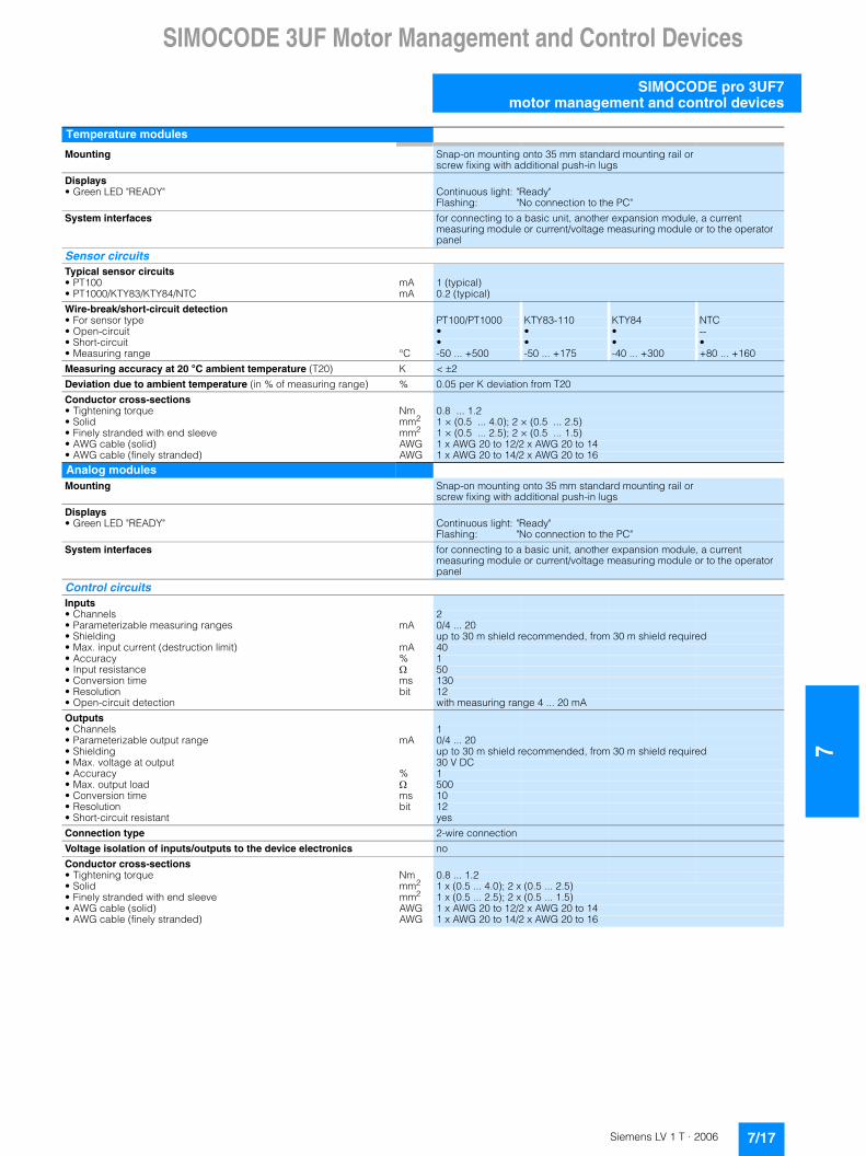
Temperature modules
Mounting Snap-on mounting onto 35 mm standard mounting rail orscrew fixing with additional push-in lugs
Displays• Green LED "READY" Continuous light: "Ready"
Flashing: "No connection to the PC"
System interfaces for connecting to a basic unit, another expansion module, a current measuring module or current/voltage measuring module or to the operator panel
Sensor circuitsTypical sensor circuits• PT100 mA 1 (typical)• PT1000/KTY83/KTY84/NTC mA 0.2 (typical)
Wire-break/short-circuit detection• For sensor type PT100/PT1000 KTY83-110 KTY84 NTC• Open-circuit • • • --• Short-circuit • • • •• Measuring range °C -50 ... +500 -50 ... +175 -40 ... +300 +80 ... +160
Measuring accuracy at 20 °C ambient temperature (T20) K < �2
Deviation due to ambient temperature (in % of measuring range) % 0.05 per K deviation from T20
Conductor cross-sections• Tightening torque Nm 0.8 ... 1.2• Solid mm2 1 × (0.5 ... 4.0); 2 × (0.5 ... 2.5)• Finely stranded with end sleeve mm2 1 × (0.5 ... 2.5); 2 × (0.5 ... 1.5)• AWG cable (solid) AWG 1 x AWG 20 to 12/2 x AWG 20 to 14• AWG cable (finely stranded) AWG 1 x AWG 20 to 14/2 x AWG 20 to 16
Analog modulesMounting Snap-on mounting onto 35 mm standard mounting rail or
screw fixing with additional push-in lugs
Displays• Green LED "READY" Continuous light: "Ready"
Flashing: "No connection to the PC"
System interfaces for connecting to a basic unit, another expansion module, a current measuring module or current/voltage measuring module or to the operator panel
Control circuitsInputs• Channels 2• Parameterizable measuring ranges mA 0/4 ... 20• Shielding up to 30 m shield recommended, from 30 m shield required• Max. input current (destruction limit) mA 40• Accuracy % 1• Input resistance � 50• Conversion time ms 130• Resolution bit 12• Open-circuit detection with measuring range 4 ... 20 mA
Outputs• Channels 1• Parameterizable output range mA 0/4 ... 20• Shielding up to 30 m shield recommended, from 30 m shield required• Max. voltage at output 30 V DC• Accuracy % 1• Max. output load � 500• Conversion time ms 10• Resolution bit 12• Short-circuit resistant yes
Connection type 2-wire connection
Voltage isolation of inputs/outputs to the device electronics no
Conductor cross-sections• Tightening torque Nm 0.8 ... 1.2• Solid mm2 1 x (0.5 ... 4.0); 2 x (0.5 ... 2.5)• Finely stranded with end sleeve mm2 1 x (0.5 ... 2.5); 2 x (0.5 ... 1.5)• AWG cable (solid) AWG 1 x AWG 20 to 12/2 x AWG 20 to 14• AWG cable (finely stranded) AWG 1 x AWG 20 to 14/2 x AWG 20 to 16
7/17Siemens LV 1 T · 2006
7SIMOCODE 3UF Motor Management and Control Devices
SIMOCODE pro 3UF7 motor management and control devices
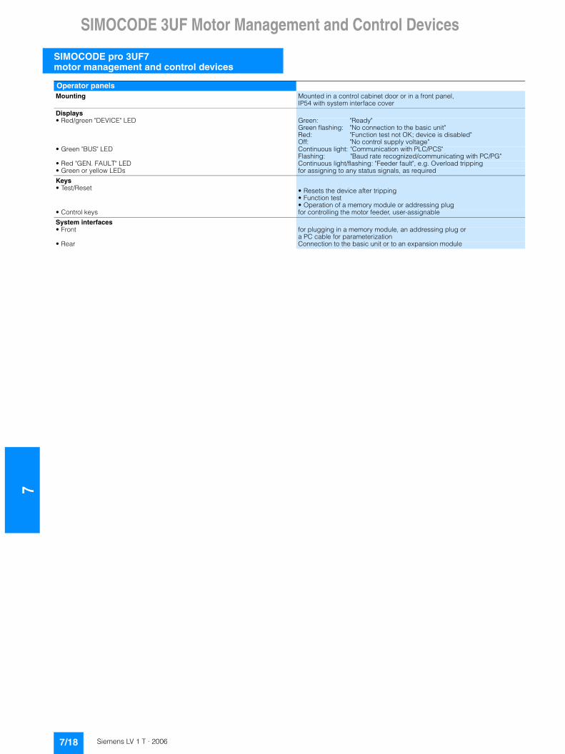
Operator panelsMounting Mounted in a control cabinet door or in a front panel,
IP54 with system interface cover
Displays• Red/green "DEVICE" LED Green: "Ready"
Green flashing: "No connection to the basic unit"Red: "Function test not OK; device is disabled"Off: "No control supply voltage"
• Green "BUS" LED Continuous light: "Communication with PLC/PCS"Flashing: "Baud rate recognized/communicating with PC/PG"
• Red "GEN. FAULT" LED Continuous light/flashing: "Feeder fault", e.g. Overload tripping• Green or yellow LEDs for assigning to any status signals, as required
Keys• Test/Reset • Resets the device after tripping
• Function test• Operation of a memory module or addressing plug
• Control keys for controlling the motor feeder, user-assignable
System interfaces• Front for plugging in a memory module, an addressing plug or
a PC cable for parameterization• Rear Connection to the basic unit or to an expansion module
7/18 Siemens LV 1 T · 2006
SIMOCODE 3UF Motor Management and Control Devices
7
SIMOCODE pro 3UF7motor management and control devices
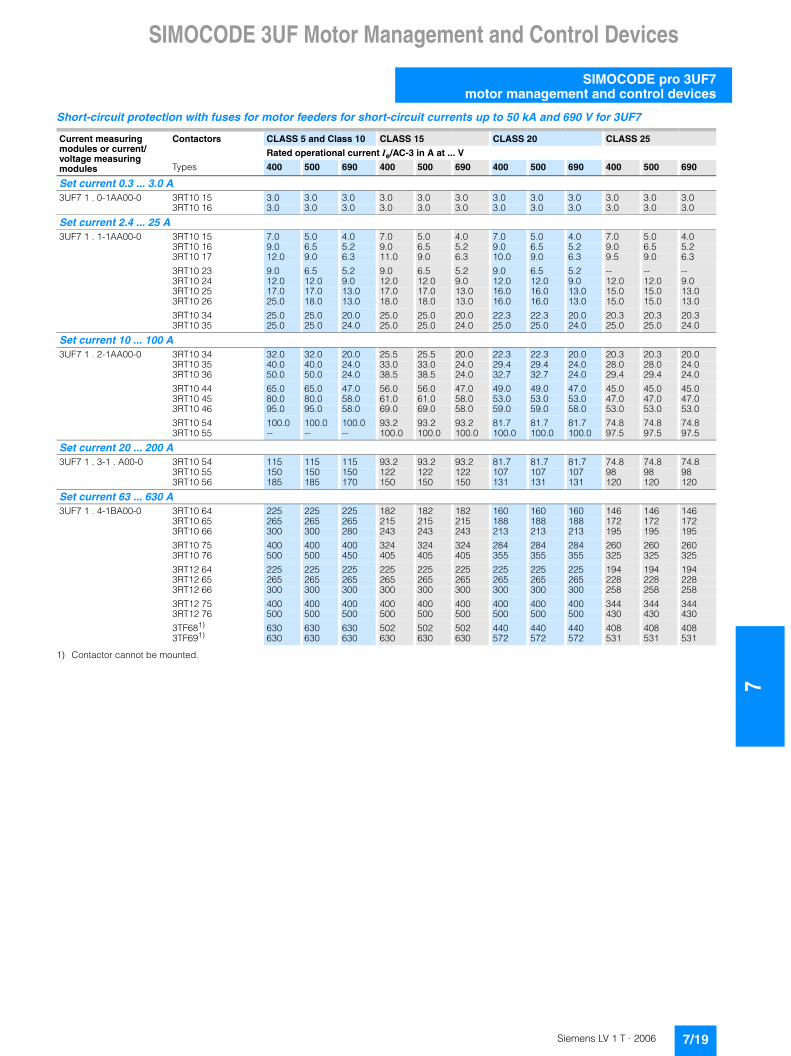
Short-circuit protection with fuses for motor feeders for short-circuit currents up to 50 kA and 690 V for 3UF7
1) Contactor cannot be mounted.
Current measuring modules or current/ voltage measuring modules
Contactors CLASS 5 and Class 10 CLASS 15 CLASS 20 CLASS 25
Rated operational current Ie/AC-3 in A at ... V
Types 400 500 690 400 500 690 400 500 690 400 500 690
Set current 0.3 ... 3.0 A3UF7 1 . 0-1AA00-0 3RT10 15 3.0 3.0 3.0 3.0 3.0 3.0 3.0 3.0 3.0 3.0 3.0 3.0
3RT10 16 3.0 3.0 3.0 3.0 3.0 3.0 3.0 3.0 3.0 3.0 3.0 3.0
Set current 2.4 ... 25 A3UF7 1 . 1-1AA00-0 3RT10 15 7.0 5.0 4.0 7.0 5.0 4.0 7.0 5.0 4.0 7.0 5.0 4.0
3RT10 16 9.0 6.5 5.2 9.0 6.5 5.2 9.0 6.5 5.2 9.0 6.5 5.23RT10 17 12.0 9.0 6.3 11.0 9.0 6.3 10.0 9.0 6.3 9.5 9.0 6.3
3RT10 23 9.0 6.5 5.2 9.0 6.5 5.2 9.0 6.5 5.2 -- -- --3RT10 24 12.0 12.0 9.0 12.0 12.0 9.0 12.0 12.0 9.0 12.0 12.0 9.03RT10 25 17.0 17.0 13.0 17.0 17.0 13.0 16.0 16.0 13.0 15.0 15.0 13.03RT10 26 25.0 18.0 13.0 18.0 18.0 13.0 16.0 16.0 13.0 15.0 15.0 13.0
3RT10 34 25.0 25.0 20.0 25.0 25.0 20.0 22.3 22.3 20.0 20.3 20.3 20.33RT10 35 25.0 25.0 24.0 25.0 25.0 24.0 25.0 25.0 24.0 25.0 25.0 24.0
Set current 10 ... 100 A3UF7 1 . 2-1AA00-0 3RT10 34 32.0 32.0 20.0 25.5 25.5 20.0 22.3 22.3 20.0 20.3 20.3 20.0
3RT10 35 40.0 40.0 24.0 33.0 33.0 24.0 29.4 29.4 24.0 28.0 28.0 24.03RT10 36 50.0 50.0 24.0 38.5 38.5 24.0 32.7 32.7 24.0 29.4 29.4 24.0
3RT10 44 65.0 65.0 47.0 56.0 56.0 47.0 49.0 49.0 47.0 45.0 45.0 45.03RT10 45 80.0 80.0 58.0 61.0 61.0 58.0 53.0 53.0 53.0 47.0 47.0 47.03RT10 46 95.0 95.0 58.0 69.0 69.0 58.0 59.0 59.0 58.0 53.0 53.0 53.0
3RT10 54 100.0 100.0 100.0 93.2 93.2 93.2 81.7 81.7 81.7 74.8 74.8 74.83RT10 55 -- -- -- 100.0 100.0 100.0 100.0 100.0 100.0 97.5 97.5 97.5
Set current 20 ... 200 A3UF7 1 . 3-1 . A00-0 3RT10 54 115 115 115 93.2 93.2 93.2 81.7 81.7 81.7 74.8 74.8 74.8
3RT10 55 150 150 150 122 122 122 107 107 107 98 98 983RT10 56 185 185 170 150 150 150 131 131 131 120 120 120
Set current 63 ... 630 A3UF7 1 . 4-1BA00-0 3RT10 64 225 225 225 182 182 182 160 160 160 146 146 146
3RT10 65 265 265 265 215 215 215 188 188 188 172 172 1723RT10 66 300 300 280 243 243 243 213 213 213 195 195 195
3RT10 75 400 400 400 324 324 324 284 284 284 260 260 2603RT10 76 500 500 450 405 405 405 355 355 355 325 325 325
3RT12 64 225 225 225 225 225 225 225 225 225 194 194 1943RT12 65 265 265 265 265 265 265 265 265 265 228 228 2283RT12 66 300 300 300 300 300 300 300 300 300 258 258 258
3RT12 75 400 400 400 400 400 400 400 400 400 344 344 3443RT12 76 500 500 500 500 500 500 500 500 500 430 430 430
3TF681) 630 630 630 502 502 502 440 440 440 408 408 4083TF691) 630 630 630 630 630 630 572 572 572 531 531 531
7/19Siemens LV 1 T · 2006

7SIMOCODE 3UF Motor Management and Control Devices
SIMOCODE pro 3UF7 motor management and control devices
1) Note the operational voltage.
2) Assignment and short-circuit protective devices acc. to IEC 60947-4-1.
Type of coordination "1": Contactors or starters must not endanger persons or equipment in the event of a short-circuit. They do not have to be suitable for further operation without repair and the renewal of parts.
Type of coordination "2": Contactors or starters must not endanger persons or equipment in the event of a short-circuit and must be suitable for continued use. There is a risk of contact welding.
3) Contactor cannot be mounted.
4) Please ensure that the maximum AC-3 operational current has a sufficient safety clearance from the rated fuse current.
Current measuring modules or current/ voltage measuring modules
Contactors CLASS 30 CLASS 35 CLASS 40 Fuse links1)
LV HRC type 3NADIAZED type 5SB
NEOZED type 5SEOperational class gL(gG)
Types of coordination2)
Rated operational current Ie/AC-3 in A at ... V 1 2
Types 400 V 500 V 690 V 400 V 500 V 690 V 400 V 500 V 690 V 690 V 690 V
Set current 0.3 ... 3.0 A3UF7 1 . 0-1AA00-0 3RT10 15 3.0 3.0 3.0 3.0 3.0 3.0 3.0 3.0 3.0 35 20
3RT10 16 3.0 3.0 3.0 3.0 3.0 3.0 3.0 3.0 3.0 35 20
Set current 2.4 ... 25 A3UF7 1 . 1-1AA00-0 3RT10 15 7.0 5.0 4.0 7.0 5.0 4.0 7.0 5.0 4.0 35 20
3RT10 16 9.0 6.5 5.2 9.0 6.5 5.2 8.5 6.5 5.2 35 203RT10 17 9.0 9.0 6.3 9.0 9.0 6.3 8.5 8.5 6.3 35 20
3RT10 23 -- -- -- -- -- -- -- -- -- 63 253RT10 24 12.0 12.0 9.0 12.0 12.0 9.0 12.0 12.0 9.0 63 253RT10 25 14.0 14.0 13.0 13.0 13.0 13.0 12.0 12.0 12.0 63 253RT10 26 14.0 14.0 13.0 13.0 13.0 13.0 12.0 12.0 12.0 100 35
3RT10 34 19.1 19.1 19.1 17.6 17.6 17.6 16.1 16.1 16.1 125 633RT10 35 25.0 25.0 24.0 25.0 25.0 24.0 23.5 23.5 23.5 125 63
Set current 10 ... 100 A3UF7 1 . 2-1AA00-0 3RT10 34 19.1 19.1 19.1 17.6 17.6 17.6 16.1 16.1 16.1 125 63
3RT10 35 26.5 26.5 24.0 25.0 25.0 24.0 23.5 23.5 23.5 125 633RT10 36 26.5 26.5 24.0 25.0 25.0 24.0 23.5 23.5 23.5 160 80
3RT10 44 41.7 41.7 41.7 38.2 38.2 38.2 34.5 34.5 34.5 200 1253RT10 45 45.0 45.0 45.0 43.0 43.0 43.0 40.0 40.0 40.0 200 1603RT10 46 50.0 50.0 50.0 47.0 47.0 47.0 44.0 44.0 44.0 200 160
3RT10 54 69.0 69.0 69.0 63.0 63.0 63.0 57.0 57.0 57.0 355 3153RT10 55 90.0 90.0 90.0 82.0 82.0 82.0 74.0 74.0 74.0 355 315
Set current 20 ... 200 A3UF7 1 . 3-1 . A00-0 3RT10 54 69.0 69.0 69.0 64.0 64.0 64.0 -- -- -- 355 315
3RT10 55 90 90 90 82 82 82 74 74 74 355 3153RT10 56 111 111 111 102 102 102 93 93 93 355 315
Set current 63 ... 630 A3UF7 1 . 4-1BA00-0 3RT10 64 135 135 135 126 126 126 -- -- -- 500 400
3RT10 65 159 159 159 146 146 146 133 133 133 500 4003RT10 66 180 180 180 165 165 165 150 150 150 500 400
3RT10 75 240 240 240 220 220 220 200 200 200 630 4003RT10 76 300 300 300 275 275 275 250 250 250 630 500
3RT12 64 173 173 173 152 152 152 131 131 131 500 5003RT12 65 204 204 204 180 180 180 156 156 156 500 5003RT12 66 231 231 231 204 204 204 177 177 177 500 500
3RT12 75 316 316 316 -- -- -- -- -- -- 800 8003RT12 76 385 385 385 340 340 340 316 316 316 800 800
3TF683) 376 376 376 344 344 344 317 317 317 800 5004) 3TF693) 500 500 500 469 469 469 438 438 438 800 6304)
7/20 Siemens LV 1 T · 2006

SIMOCODE 3UF Motor Management and Control Devices
7
SIMOCODE pro 3UF7motor management and control devices
■ Dimension drawings
Basic unit 1, SIMOCODE pro C, 3UF7 000
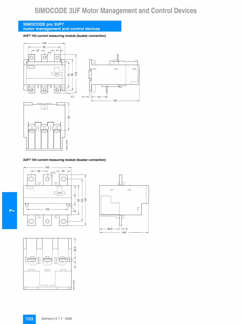
3UF7 100, 3UF7 101 current measuring module (straight-through transformer)
Basic unit 2, SIMOCODE pro V, 3UF7 010
3UF7 102 current measuring module (straight-through transformer)
3UF7 103 current measuring module (straight-through transformer)
� �� � �
�� ���
��
�
�
������ �
� �
���������
� � � ��
��
��
� �� �
� �
� �
�� ���
��
�
� �� � �
� � ��
������ �
� � �
��
��
� �
�
��������
� �
� �
� �
� � �
� �
�
��
� � � �
�
� �
��������
7/21Siemens LV 1 T · 2006
7SIMOCODE 3UF Motor Management and Control Devices
SIMOCODE pro 3UF7 motor management and control devices
3UF7 103 current measuring module (busbar connection)
3UF7 104 current measuring module (busbar connection)
��������
� � �
� �
� � �
� ��
���
�
� � �
�
��
� � �
�
� �� �� �
�
��
���
��
� � �
�
� � �
� � � �
����
���������
7/22 Siemens LV 1 T · 2006
SIMOCODE 3UF Motor Management and Control Devices
7
SIMOCODE pro 3UF7motor management and control devices
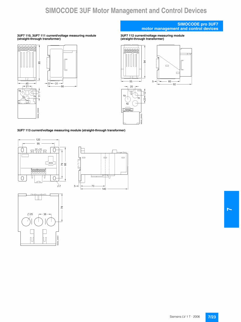
3UF7 110, 3UF7 111 current/voltage measuring module (straight-through transformer)
3UF7 112 current/voltage measuring module (straight-through transformer)
3UF7 113 current/voltage measuring module (straight-through transformer)
��
� � � ��� �
��
� �
��������
� �
� �
� �
� �
��
� �� � �
� �
��
��
��������
� �
� �
� �
� � �
� �
�
��
�� � �
�
� �
��������
� �
�
7/23Siemens LV 1 T · 2006

7SIMOCODE 3UF Motor Management and Control Devices
SIMOCODE pro 3UF7 motor management and control devices
3UF7 113 current/voltage measuring module (busbar connection)
3UF7 114 current/voltage measuring module (busbar connection)
3UF7 200 operator panel
��������
� � �
� �
� � �
� ��
���
�
� � �
�
�
6
14967
8832125
147
122
254811
9
NSA0_00404
145
��
� � � � �
��
� � � � � � � �
7/24 Siemens LV 1 T · 2006
SIMOCODE 3UF Motor Management and Control Devices
7
SIMOCODE pro 3UF7motor management and control devices
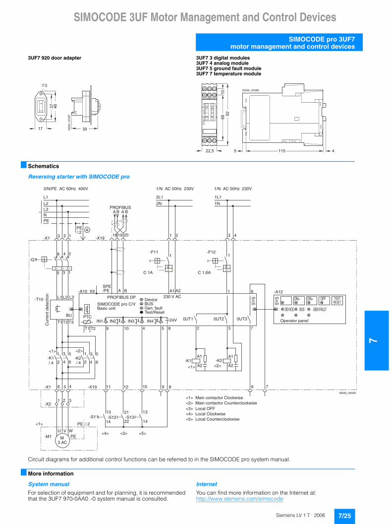
3UF7 920 door adapter 3UF7 3 digital modules3UF7 4 analog module3UF7 5 ground fault module3UF7 7 temperature module
■ Schematics
Reversing starter with SIMOCODE pro
Circuit diagrams for additional control functions can be referred to in the SIMOCODE pro system manual.
■ More information
System manual
For selection of equipment and for planning, it is recommended that the 3UF7 970-0AA0.-0 system manual is consulted.
Internet
You can find more information on the Internet at:http://www.siemens.com/simocode
�������
�
��
�
�
� �
� � �� �
��
�� ��
� � � �
� � � � � � � �
��
���
����
��
� � ���
� �
� � �
��
�� �� ��
���� ��
��
���
��
���
� � �
� �
� � �
� �
� � ��
��
���
��
� � �
� � �
�����
�� ��
���� �� ���
������ � ���
�
�� ��
� �
���
��
�������������� ������
�!"#$���
����������� ������ ����������� ������
���
��
�
�
#�� #��
� �
�!"#$����%�
�� ��
���$��$��$��$��
�� �� �� ��� ��� ���
�� �� ��
�� �� �� � � ���
���
&����
��
�� &����
��
��
���� ����
�'�
%��$��
�'�
(
��� ���
����
�� � �
���
&���
���
&���
��
� �� � � � � � (
���
���� ���)�� � � � �
��� *��#����
����+�����
���
������,-.�/0.1,/102��30/45-67������,-.�/0.1,/102��08.172/30/45-67������0/,3�"##������0/,3��30/45-67������0/,3��08.172/30/45-67
"972,102�9,.73
%7:-/7���*7.�;,831�761�!7671
�$�"�"%��920�����,6-/�8.-1
�8227.1�<717/
1-0.
"�� "�� "## ����!����
��������
7/25Siemens LV 1 T · 2006
7SIMOCODE 3UF Motor Management and Control Devices
SIMOCODE-DP 3UF5motor protection and control devices
■ Overview
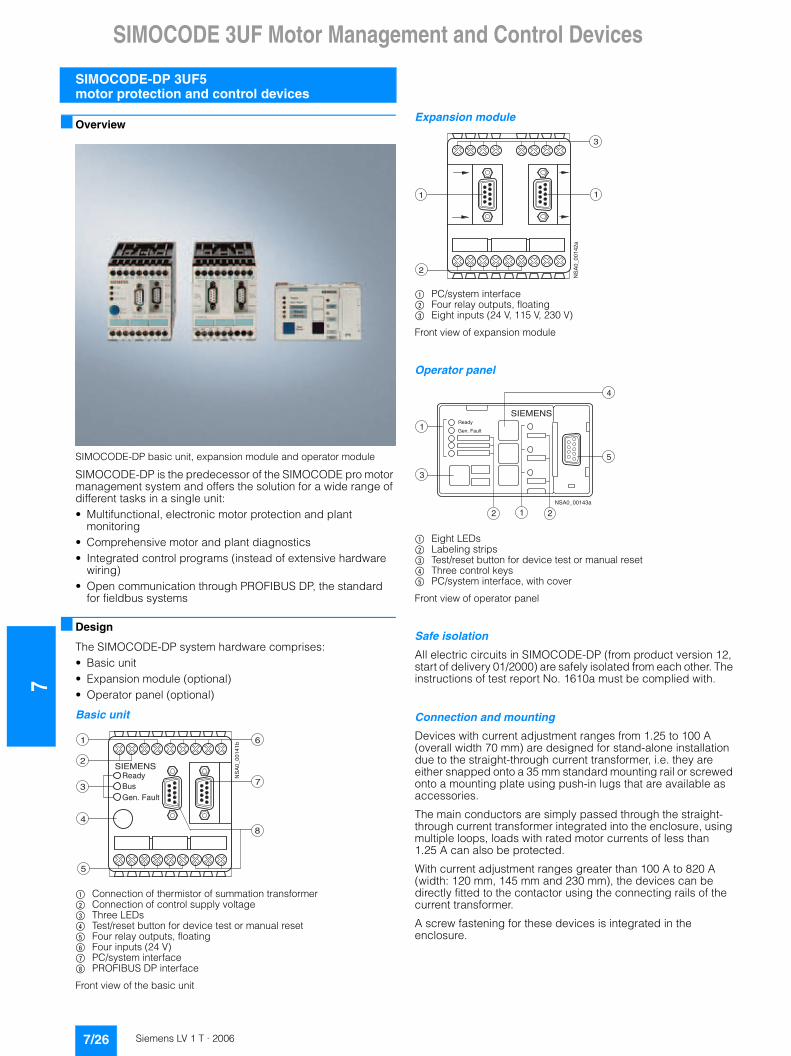
SIMOCODE-DP basic unit, expansion module and operator module
SIMOCODE-DP is the predecessor of the SIMOCODE pro motor management system and offers the solution for a wide range of different tasks in a single unit:• Multifunctional, electronic motor protection and plant
monitoring• Comprehensive motor and plant diagnostics• Integrated control programs (instead of extensive hardware
wiring)• Open communication through PROFIBUS DP, the standard
for fieldbus systems
■ Design
The SIMOCODE-DP system hardware comprises:• Basic unit• Expansion module (optional)• Operator panel (optional)
Basic unit
$ Connection of thermistor of summation transformer% Connection of control supply voltage& Three LEDs( Test/reset button for device test or manual reset) Four relay outputs, floating* Four inputs (24 V)+ PC/system interface, PROFIBUS DP interface
Front view of the basic unit
Expansion module
$ PC/system interface% Four relay outputs, floating& Eight inputs (24 V, 115 V, 230 V)
Front view of expansion module
Operator panel
$ Eight LEDs% Labeling strips& Test/reset button for device test or manual reset( Three control keys) PC/system interface, with cover
Front view of operator panel
Safe isolation
All electric circuits in SIMOCODE-DP (from product version 12, start of delivery 01/2000) are safely isolated from each other. The instructions of test report No. 1610a must be complied with.
Connection and mounting
Devices with current adjustment ranges from 1.25 to 100 A (overall width 70 mm) are designed for stand-alone installation due to the straight-through current transformer, i.e. they are either snapped onto a 35 mm standard mounting rail or screwed onto a mounting plate using push-in lugs that are available as accessories.
The main conductors are simply passed through the straight-through current transformer integrated into the enclosure, using multiple loops, loads with rated motor currents of less than 1.25 A can also be protected.
With current adjustment ranges greater than 100 A to 820 A (width: 120 mm, 145 mm and 230 mm), the devices can be directly fitted to the contactor using the connecting rails of the current transformer.
A screw fastening for these devices is integrated in the enclosure.
5
SIEMENS
1 6
2
3
48
7
NS
A0_
0014
1b
ReadyBusGen. Fault
2
3
1 1
NS
A0_
0014
2a
SIEMENS
NSA0_00143a
Ready
Gen. Fault1
3
4
5
2 1 2
7/26 Siemens LV 1 T · 2006

SIMOCODE 3UF Motor Management and Control Devices
7
SIMOCODE-DP 3UF5motor protection and control devices
■ Function
Protective and monitoring functions
For the protection of loads against impermissible high temperature rises
Types of overload protection:• Current-sensitive, electronic overload protection with
adjustable tripping characteristics (class times) SIMOCODE-DP protects three-phase or AC motors from overloading according to the requirements of IEC 60947-4-1. The class (trip class) indicates the maximum tripping time during which SIMOCODE-DP must trip at 7.2 times the operational current from cold. The trip class can be set in six stages from Class 5 to Class 30. The break time can therefore be extremely finely adjusted to the load torque of the motor – to optimize utilization of the motor (see also the section Characteristic Curves).
• Phase failure/unbalance monitoring A signal is output for a phase unbalance greater than 40 %. The tripping times of the overload characteristic are reduced, because the heat generated in the motor rises under unbalanced conditions (additional eddy-current losses).
• Thermistor motor protection Temperature-dependent motor protection is based on direct temperature measurements in the motor. These protective functions should be used, in particular, in motors with high operating frequencies, heavy-duty starting, intermittent and/or braking operation, but also in the case of a blocked air supply or speeds lower than the rated speed. For this reason, a wide range of different temperature sensors are available that are installed in the stator winding or in the motor enclosure. SIMOCODE-DP can evaluate the following sensor types:
- Binary PTC sensors whose resistance rises sharply when the temperature limit is reached
- Analog temperature sensors, such as NTC, KTY83/84, which have an almost linear characteristic curve and can therefore be set to any warning or switch-off temperatures
EEx e type of protection
The SIMOCODE-DP system is in compliance with the regulations for overload protection of explosion-protected motors of theEEx e "Increased safety" type of protection according to• EN 50019• EN 60079-7, IEC 60079-7• EN 60079-14 (potentially explosive areas)• EN 50281 (areas with combustible dust)• ATEX/PTB test regulations
In the case of SIMOCODE-DP units with 24 V DC control infeed, isolation by battery or safety transformer according to EN 61558-2-6 must be assured.
EC type test certificate: PTB01 ATEX 3219
Test report: PTB EX 01-30013
Rotor locking protection
When the motor current rises above a rotor locking threshold that can be set, SIMOCODE-DP does not trip according to the overload characteristic, but switches off immediately instead. The prevention of unnecessary thermal loads prevents premature aging of the motor. The rotor locking protection is not active for start-up monitoring until the class time has elapsed, e.g. for Class 10 after 10 seconds.
Ground-fault monitoring
Two qualitatively different ground-fault monitoring functions are offered:• "Internal" ground-fault monitoring by means of calculation
The internal ground-fault monitoring is only suitable for motors with 3-wire connection and for networks that are grounded directly or with a low impedance. In this case, the ground-fault current is calculated by vector addition of the phase currents of the SIMOCODE-DP current transformer. An additional summation current transformer is not necessary. In fault-free systems, the vectorial summation current of the three phases is zero; if this is not the case, a ground-fault is signaled. Ground-fault currents that are more than 30 % of the operating current Ie are detected.
• "Internal" ground-fault monitoring by means of measurement The external ground-fault detection is normally used in supply systems that have a high impedance ground. An additional summation current transformer (3UL2 20.-.A) is required for this method that is also suitable for extremely low ground-fault currents. Detected fault current, depending on the summation current transformer: 0.3/0.5/1 A.
Current limit monitoring I>, I<
Current limit monitoring is not used for motor protection, but for process monitoring.
It is used to detect developing irregularities in the plant early, e.g. motor bearings becoming tight (consequence: upper limit responds) or the belt coupling to the drive machine tears (consequence: lower limit responds).
Comprehensive motor and plant diagnostics
SIMOCODE-DP provides a variety of measuring, operating and diagnostics data concerning the load feeder: • Up-to-date information during operation, e.g.:
- The currently flowing phase current in %- The switching state of the motor (On, Off, clockwise,
counterclockwise, fast, slow) derived from the current flow- Manual/automatic mode- Test mode- Cooling time activated after an overload tripping operation
• Detection of incipient faults, e.g.: - Overload warning- Current limit overshoot- Phase unbalance- Thermistor warning
• Rapid diagnostics in the event of an alarm, e.g.: - Overload- Thermistor motor protection- Rotor locking- Current limit overshoot- Checkback error (e.g. no current following On command)
• Preventive maintenance by means of statistical data, e.g.: - Number of starts- Number of overload trips- Tripping currents- Operating hours
Integrated standard programs for motor control
In SIMOCODE-DP, a number of different opportunities for controlling the motor has been predefined and can be called up in the form of control functions:• Overload relay• Direct-on-line starter• Reversing starter• Wye-delta starter
7/27Siemens LV 1 T · 2006
7SIMOCODE 3UF Motor Management and Control Devices
SIMOCODE-DP 3UF5motor protection and control devices
• Two speeds, Dahlander winding• Two speeds, separate winding• Valve• Actuator• Soft starter (3RW)
These control programs already include all the software interlocks and logic operations required for operation of the required motor functions.
It is also monitored whether the current checkback of the motor feeder corresponds with the control command. If not, SIMOCODE-DP opens the motor contactor and generates an alarm indication.
The motor can be controlled by any equipment depending on the application:• From the process control system or the PC through
PROFIBUS DP• From the control cabinet door through the operator panel• From a local control point on the motor, whereby the
pushbuttons/switches are wired to the SIMOCODE-DP inputs
The standard control functions can also be adapted to each customized variant of a motor feeder by means of freely-parameterizable elements, such as timers, counters, logic operations (AND, OR, NOR, etc.).
Furthermore, special standard function blocks are stored in SIMOCODE-DP:• Automatic, time-discrete reactivation of motors following
mains failure The prerequisites are as follows:
- Failure of the three-phase supply must take place through a separate voltage relay
- The supply voltage of SIMOCODE-DP must not be interrupted
• Different error signaling modules with and without acknowledgement These allow SIMOCODE-DP to trip as a result of external events (e.g. overspeed monitor has tripped)
• The emergency start function This resets the thermal memory of SIMOCODE-DP immediately after overload tripping, i.e. immediate restarting is possible (important, for example, for a fire-extinguisher pump)
• The test function for the load feeder This can be activated by switching off the main switch Q1 (see the section Schematics) and allows the control circuit to be checked with the motor branch at zero current.
■ Integration
The SIMOCODE-DP modular system offers a wide range of software packages for system-wide and time-saving configuration and diagnostics:• PC software Win-SIMOCODE-DP for start-up and service• Object manager OM-SIMOCODE for "totally integrated" in
SIMATIC S7• Function block FB-SIMOCODE for "totally integrated" in PCS7
PC software Win-SIMOCODE-DP for start-up and service
Standard PC software Win-SIMOCODE-DP for start-up and service. It offers a user-friendly and convenient user-interface for:• Parameterization• Display and diagnostics• Test functions• Motor control
Win-SIMOCODE-DP is available in two versions:• Win-SIMOCODE-DP/Smart
for direct connection to SIMOCODE-DP through the system interface on the device
• Win-SIMOCODE-DP/Professional for direct connection to SIMOCODE-DP over PROFIBUS or directly through the system interface on the device
OM-SIMOCODE object manager for "totally integrated" in SIMATIC S7
SIMOCODE-DP can be integrated into SIMATIC S7 in two different ways:• Conventionally using GSD files
i.e. integration in SIMATIC S7 is identical to integration in any other DP standard master system
• Using the OM-SIMOCODE-DP object manager i.e. SIMOCODE-DP becomes an integral component of STEP 7; the OM-SIMOCODE-DP object manager should, in this case, always be combined with the start-up and service software Win-SIMOCODE-DP/Professional
Both software packages must be installed on the PG/PC on which the hardware configuration of SIMATIC S7 is performed. This ensures that Win-SIMOCODE-DP/Professional can be called up directly from HW-Config.
Parameter sets created with Win-SIMOCODE-DP/Professional are loaded into the STEP 7 data storage by means of OM and automatically transferred to SIMOCODE-DP during start-up.
Functions specific to SIMATIC S7, such as diagnostic and hardware interrupts are supported, which means easier S7-wide configuration as well as optimal performance in the transfer of diagnostic data.
Function block FB-SIMOCODE for "totally integrated" in PCS7
With PCS7-FB SIMOCODE-DP it is easy and convenient to integrate SIMOCODE-DP into the SIMATIC PCS 7 process control system. PCS7-FB SIMOCODE-DP contains the diagnostic and driver blocks corresponding with the diagnostic and driver concept of SIMATIC PCS 7 as well as the elements (symbols and faceplate) required for operator control and process monitoring. The application is integrated by graphic interconnection using the CFC Editor. The technological and signal processing functions of the PCS7-FB SIMOCODE-DP are based on the SIMATIC PCS 7 standard libraries (driver blocks, technological blocks) and are optimally tailored to SIMOCODE-DP. Users who previously configured motor feeder circuits using conventional technology by means of signal blocks and motor or valve blocks, can now easily switch to PCS7-FB SIMOCODE-DP. The PCS7-FB SIMOCODE-DP supplied on CD-ROM allows the user to run the required engineering software on one engineering station (single license) including the runtime software for executing the AS blocks in an automation system (single license).
7/28 Siemens LV 1 T · 2006

SIMOCODE 3UF Motor Management and Control Devices
7
SIMOCODE-DP 3UF5motor protection and control devices
■ Technical specifications
Shared data of basic units/expansion units/expansion modules/operator panels
Permissible ambient temperature °C -25 ... +60
Permissible storage temperature °C -40 ... +80
Installation altitude above sea level m � 2000
Degree of protection (acc. to IEC 60529) IP20 max. set current Ie � 100 A; IP00 max. set current Ie > 100 A
Shock resistance (sine pulse) g/ms 10/5
Mounting position Any
Mounting• Max. set current Ie � 100 A Snap-on mounting onto 35 mm standard mounting rail or
screw fixing with push-in lugs• Max. set current Ie > 100 A Screw fixing directly onto contactor or screw fixing
EMC interference immunity• Conducted interference, burst acc. to IEC 61000-4-4 kV 2 (corresponds to degree of severity 3)• Conducted interference, surge acc. to IEC 61000-4-5 kV 2 (corresponds to degree of severity 3)• Electrostatic discharge acc. to IEC 61000-4-2 kV 8 (corresponds to degree of severity 3)• Field-related interference acc. to IEC 61000-4-3 V/m 10 (corresponds to degree of severity 3)
EMC interference emission Limit class B acc. to EN 55011 (VDE 0875 Part 11)
Safe isolation(product version 12 upwards, start of delivery 01/2000)
All electric circuits in SIMOCODE-DP are safely isolated from each other, i.e. they are designed with double leakage paths and clearancesPower circuit from the control/electronic circuits:Safe isolation up to 690 V or 1000 V between control and electronic circuitsOne below the other: Safe isolation up to 300 VObserve notes of test report "Safe Isolation" No. 1610a.
Basic units
Displays• Green "Ready" LED Continuous light: "Ready"
Off: "No control supply voltage" or "Function test not OK; device is disabled"• Green "BUS" LED Continuous light: "Bus operation"• Red "General Fault" LED Continuous light/blinklight: "Feeder fault", e.g. overload tripping
Test/Reset buttons By pressing the Test/Reset button, the device can be reset following a trip or its functions can be tested
System interfaces RS 232 for connecting the expansion module, operator panel or PC
PROFIBUS DP interface RS 485 for connecting the PROFIBUS DP line using terminals (conductor cross-sections as for auxiliary contacts) or 9-pole SUB D socket
Main circuits
Rated insulation voltage Ui (with pollution degree 3)• For uninsulated conductors (3UF5 001 to 3UF5 021) V 690• For insulated conductors (3UF5 001 to 3UF5 021) V 1000• For uninsulated and insulated conductors
(3UF5 031 to 3UF5 051)V 1000
Rated impulse withstand voltage Uimp• 3UF5 001 to 3UF5 021 kV 6• 3UF5 031 to 3UF5 051 kV 8
Rated frequency Hz 50/60
Type of current Three-phase current
Short-circuit protection See table Short-circuit protection with fuses for motor feeders, page 7/31
Diameters of feed-through openings(max. Ie = 100 A)• Devices with max. set current Ie � 25 A mm 10• Devices with max. set current Ie � 100 A mm 15• Devices with max. set current Ie > 100 A Design with connecting bars
Busbar connections
• Current range A 50 ... 205 125 ... 500 200 ... 820• Tightening torque Nm M 8: 10 ... 14 M 10: 14 ... 24 M 10: 14 ... 24
M 12: 20 ... 35• Finely stranded with cable lug mm2 35 ... 95 50 ... 240 50 ... 240• Stranded with cable lug mm2 50 ... 120 70 ... 240 70 ... 240
7/29Siemens LV 1 T · 2006

7SIMOCODE 3UF Motor Management and Control Devices
SIMOCODE-DP 3UF5motor protection and control devices
Auxiliary circuits/control circuits
Rated control supply voltage Us AC 50/60 Hz; 115 V and 230 V 24 V DC
Operating range AC 50/60 Hz 0.85 ... 1.1 x Us 24 V DC; 0.85 ... 1.2 � Us
Power input AC 50/60 Hz; 5 VA 24 V DC; 5 W
Rated insulation voltage Ui V 300 (at pollution degree 3)
Rated impulse withstand voltage Uimp kV 4
Outputs• Number 4 monostable/bistable outputs depending on the variant• Auxiliary contacts of the 4 outputs NC contact response can be parameterized by means of internal signal
conditioning; 3 outputs jointly and 1 separately connected to common potential; they can be freely assigned to the control functions (e.g. for activating mains, wye and delta contactors and signaling the operating status)
• Specified short-circuit protectionfor auxiliary contacts (outputs)
Fuse links, gL/gA operational class 6 A, quick 10 A; circuit-breaker 1.6 A, C characteristic
Rated uninterrupted current A 5
Rated operational current(switching capacity)
AC-15; 6 A/24 V; 6 A/120 V; 3 A/230 VDC-13; 2 A/24 V; 0.55 A/60 V; 0.25 A/125 V
Inputs 4 inputs, supplied by the device electronics (24 V DC), jointly connected to a common potential, for injecting process signals such as local control points, key-operated switches or limit switches
Thermistor motor protection(binary PTC thermistor) • Summation cold resistance k� 1.5• Operating value k� 2.7 ... 3.1• Return value k� 1.5 ... 1.65
Conductor cross-sections• Tightening torque Nm 0.8 ... 1.2• Solid and stranded mm2 1 � (0.5 ... 4.0); 2 � (0.5 ... 2.5)• Finely stranded with or without end sleeve mm2 1 � (0.5 ... 2.5); 2 � (0.5 ... 1.5)
Expansion modules
System interfaces RS 232 as connection to the basic unit and for connecting the operator panel or PC
Rated insulation voltage Ui V 300 (at pollution degree 3)
Rated impulse withstand voltage Uimp kV 4
Outputs• Number 4 bistable outputs• Auxiliary contacts of the 4 outputs Each with 1 floating NO contact, NC contact response can be parameterized with
internal signal conditioning, 3 outputs are jointly and 1 is separately connected to a common potential; they can be freely assigned to the control functions (e.g. for activating mains, wye and delta contactors and for signaling the operating status)
• Specified short-circuit protectionfor auxiliary contacts (outputs)
Fuse links, operational class gL/gA 6 A, quick 10 A; circuit-breaker 1.6 A, C characteristic
Rated uninterrupted current A 5
Rated operational current(switching capacity)
AC-15; 6 A/24 V; 6 A/120 V; 3 A/230 VDC-13; 2 A/24 V; 0.55 A/60 V; 0.25 A/125 V
Inputs 8 externally supplied with 24 V DC, 115 V AC or 230 V AC depending on the variant, jointly connected to a common potential, for injecting process signals such as local control points, key-operated switches or limit switches
Conductor cross-sections• Tightening torque Nm 0.8 ... 1.2• Solid and stranded mm2 1 � (0.5 ... 4.0); 2 � (0.5 ... 2.5)• Finely stranded with or without end sleeve mm2 1 � (0.5 ... 2.5); 2 � (0.5 ... 1.5)
Operator panels
Displays• Green "Ready" LED Continuous light: "Ready"
Off: "No control supply voltage" or "Function test not OK; device is disabled"• Red "General Fault" LED Continuous light/blinklight: "Feeder fault", e.g. overload tripping• 3 green and 3 yellow LEDs Feeder-specific displays, freely-assignable, e.g. manual/automatic mode, tripping of
thermistor protection, clockwise/counterclockwise rotation etc.
Keys• Test/Reset by pressing the Test/Reset button, the device can be reset following a trip or its
functions can be tested• Control keys for controlling the motor feeder, freely programmable
System interfaces RS 232 as connection to the basic unit, to the expansion module and for connection to PC
7/30 Siemens LV 1 T · 2006
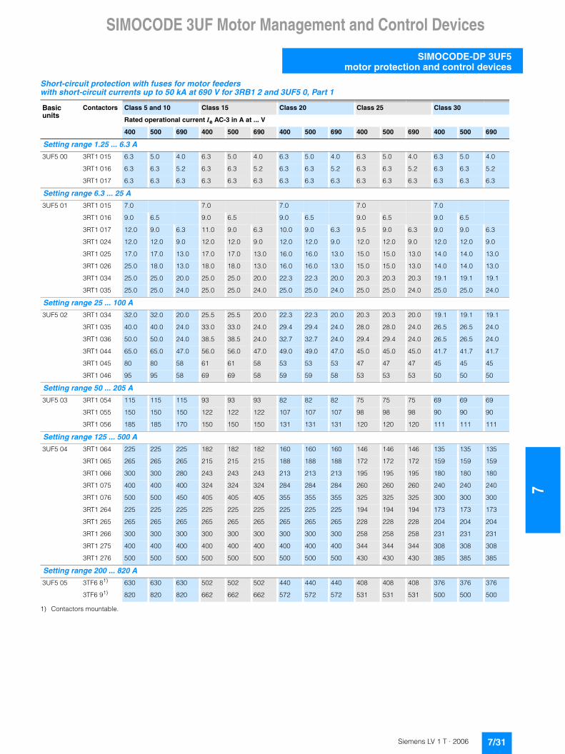
SIMOCODE 3UF Motor Management and Control Devices
7
SIMOCODE-DP 3UF5motor protection and control devices
Short-circuit protection with fuses for motor feeders with short-circuit currents up to 50 kA at 690 V for 3RB1 2 and 3UF5 0, Part 1
1) Contactors mountable.
Basic units
Contactors Class 5 and 10 Class 15 Class 20 Class 25 Class 30
Rated operational current Ie AC-3 in A at ... V
400 500 690 400 500 690 400 500 690 400 500 690 400 500 690
Setting range 1.25 ... 6.3 A
3UF5 00 3RT1 015 6.3 5.0 4.0 6.3 5.0 4.0 6.3 5.0 4.0 6.3 5.0 4.0 6.3 5.0 4.0
3RT1 016 6.3 6.3 5.2 6.3 6.3 5.2 6.3 6.3 5.2 6.3 6.3 5.2 6.3 6.3 5.2
3RT1 017 6.3 6.3 6.3 6.3 6.3 6.3 6.3 6.3 6.3 6.3 6.3 6.3 6.3 6.3 6.3
Setting range 6.3 ... 25 A
3UF5 01 3RT1 015 7.0 7.0 7.0 7.0 7.0
3RT1 016 9.0 6.5 9.0 6.5 9.0 6.5 9.0 6.5 9.0 6.5
3RT1 017 12.0 9.0 6.3 11.0 9.0 6.3 10.0 9.0 6.3 9.5 9.0 6.3 9.0 9.0 6.3
3RT1 024 12.0 12.0 9.0 12.0 12.0 9.0 12.0 12.0 9.0 12.0 12.0 9.0 12.0 12.0 9.0
3RT1 025 17.0 17.0 13.0 17.0 17.0 13.0 16.0 16.0 13.0 15.0 15.0 13.0 14.0 14.0 13.0
3RT1 026 25.0 18.0 13.0 18.0 18.0 13.0 16.0 16.0 13.0 15.0 15.0 13.0 14.0 14.0 13.0
3RT1 034 25.0 25.0 20.0 25.0 25.0 20.0 22.3 22.3 20.0 20.3 20.3 20.3 19.1 19.1 19.1
3RT1 035 25.0 25.0 24.0 25.0 25.0 24.0 25.0 25.0 24.0 25.0 25.0 24.0 25.0 25.0 24.0
Setting range 25 ... 100 A
3UF5 02 3RT1 034 32.0 32.0 20.0 25.5 25.5 20.0 22.3 22.3 20.0 20.3 20.3 20.0 19.1 19.1 19.1
3RT1 035 40.0 40.0 24.0 33.0 33.0 24.0 29.4 29.4 24.0 28.0 28.0 24.0 26.5 26.5 24.0
3RT1 036 50.0 50.0 24.0 38.5 38.5 24.0 32.7 32.7 24.0 29.4 29.4 24.0 26.5 26.5 24.0
3RT1 044 65.0 65.0 47.0 56.0 56.0 47.0 49.0 49.0 47.0 45.0 45.0 45.0 41.7 41.7 41.7
3RT1 045 80 80 58 61 61 58 53 53 53 47 47 47 45 45 45
3RT1 046 95 95 58 69 69 58 59 59 58 53 53 53 50 50 50
Setting range 50 ... 205 A
3UF5 03 3RT1 054 115 115 115 93 93 93 82 82 82 75 75 75 69 69 69
3RT1 055 150 150 150 122 122 122 107 107 107 98 98 98 90 90 90
3RT1 056 185 185 170 150 150 150 131 131 131 120 120 120 111 111 111
Setting range 125 ... 500 A
3UF5 04 3RT1 064 225 225 225 182 182 182 160 160 160 146 146 146 135 135 135
3RT1 065 265 265 265 215 215 215 188 188 188 172 172 172 159 159 159
3RT1 066 300 300 280 243 243 243 213 213 213 195 195 195 180 180 180
3RT1 075 400 400 400 324 324 324 284 284 284 260 260 260 240 240 240
3RT1 076 500 500 450 405 405 405 355 355 355 325 325 325 300 300 300
3RT1 264 225 225 225 225 225 225 225 225 225 194 194 194 173 173 173
3RT1 265 265 265 265 265 265 265 265 265 265 228 228 228 204 204 204
3RT1 266 300 300 300 300 300 300 300 300 300 258 258 258 231 231 231
3RT1 275 400 400 400 400 400 400 400 400 400 344 344 344 308 308 308
3RT1 276 500 500 500 500 500 500 500 500 500 430 430 430 385 385 385
Setting range 200 ... 820 A
3UF5 05 3TF6 81) 630 630 630 502 502 502 440 440 440 408 408 408 376 376 376
3TF6 91) 820 820 820 662 662 662 572 572 572 531 531 531 500 500 500
7/31Siemens LV 1 T · 2006

7SIMOCODE 3UF Motor Management and Control Devices
SIMOCODE-DP 3UF5motor protection and control devices
Short-circuit protection with fuses for motor feeders with short-circuit currents up to 50 kA at 690 V for 3RB1 2 and 3UF5 0, Part 2
1) Note the operational voltage.
2) Assignment and short-circuit protective devices acc. to IEC 60947-4-1:
Type of coordination "1": Contactors or starters must not endanger persons or equipment in the event of a short-circuit. They do not have to be suitable for further operation without repair and the renewal of parts.
Type of coordination "2": Contactors or starters must not endanger persons or equipment in the event of a short-circuit and must be suitable for continued use. There is a risk of contact welding.
3) Contactors mountable.
4) Ensure that the maximum AC-3 operational current is sufficiently different from the rated fuse current.
Basic units Contactors Fuse links1)
690 V 415 V 600 V
LV HRCDIAZED NEOZED Operational class gL (gG)
Type 3NAType 5SB Type 5SE
Type 3NDaM
British Standards fuses BS88
UL-listed fuses RK5/L
Type of coordination2)
1 2 500
Setting range 1.25 ... 6.3 A
3UF5 00 3RT1 015 35 20 20 253RT1 016 35 20 20 253RT1 017 35 20 20 25
Setting range 6.3 ... 25 A
3UF5 01 3RT1 015 35 20 20 603RT1 016 35 20 20 603RT1 017 35 20 20 603RT1 024 63 25 20 25 703RT1 025 63 25 20 25 703RT1 026 100 35 20 25 1003RT1 034 125 63 50 63 1003RT1 035 125 63 50 63 100
Setting range 25 ... 100 A
3UF5 02 3RT1 034 125 63 50 63 1253RT1 035 125 63 50 80 1503RT1 036 160 80 50 80 2003RT1 044 250 125 63 125 2503RT1 045 250 160 80 160 2503RT1 046 250 160 100 160 350
Setting range 50 ... 205 A
3UF5 03 3RT1 054 355 315 160 250 4503RT1 055 355 315 200 315 5003RT1 056 355 315 200 315 500
Setting range 125 ... 500 A
3UF5 04 3RT1 064 500 400 250 400 7003RT1 065 500 400 315 400 8003RT1 066 500 400 315 400 8003RT1 075 630 400 400 450 10003RT1 076 630 500 500 500 12003RT1 264 500 500 400 450 8003RT1 265 500 500 400 450 8003RT1 266 500 500 400 450 8003RT1 275 800 800 630 800 12003RT1 276 800 800 630 800 1200
Setting range 200 ... 820 A
3UF5 05 3TF6 83) 1000 5004) 630 500 12003TF6 93) 1250 6304) 630 630 2000 CLASS L
7/32 Siemens LV 1 T · 2006

SIMOCODE 3UF Motor Management and Control Devices
7
SIMOCODE-DP 3UF5motor protection and control devices
■ Characteristic curves
Tripping characteristics for three-pole loads
The current-time curves for 3-pole symmetrical load show the relationship between the release time from cold and multiples of the operational current.
If the device is pre-loaded with 100 % of the current setting, the tripping times are reduced.
Tripping characteristics for double-pole loads
In the case of 2-pole loading (failure of one phase) or current unbalance > 40 % of the current setting, the tripping times are reduced, because the heat generated due to the unbalanced loading of the motor rises.
■ Dimensional drawings
3UF5 001, 3UF5 011 and 3UF5 021 basic units
3UF5 031, 3UF5 041 and 3UF5 051 basic units
������
��
��
��
�
�
���
��
��
�
�
� � � �����
��
�� �����
���
�� �����������������������������
����������������������
�� �����
������������
������������������������
������
��
��
��
�
�
���
��
��
�
�
� � � �����
��
�� ����
���
�� �����������������������������
����������������������
�� �����
������������
������������������������
5070
4,5
85
100
e
b
af
cd
12,3
10
100
7,2
14
127,5
NSA00148
5
a b c d e f
3UF50 01 10 34 29 46 - -3UF50 11 10 34 29 46 48 43UF50 21 15 29 24 47 48 4
�
���
�
� �
�
�
�
�
�
�
�����������
�
� � � � � � � �
� � � � � � � �
� � � � � � � �
�
� � �
� � �
� � �
�
�
�
� � �
� ! �
� � �
� � �
� � �
� � �
� �
� �
! �
" � !
" � �
" � � �
� �
� �
! �
� !
�
#
� � � � � � � �
� � � � � � � �
� � � � � � � �
� � �
� � �
� � �
� �
� $
� �
� �
� �
� �
� � �
� � �
� $ $
! % �
! % �
! % �
� �
#
#
� � �
� $ �
� ! �
�
$
� � � � � �
� � � � � �
& �
& � � �
& � � �
�
7/33Siemens LV 1 T · 2006
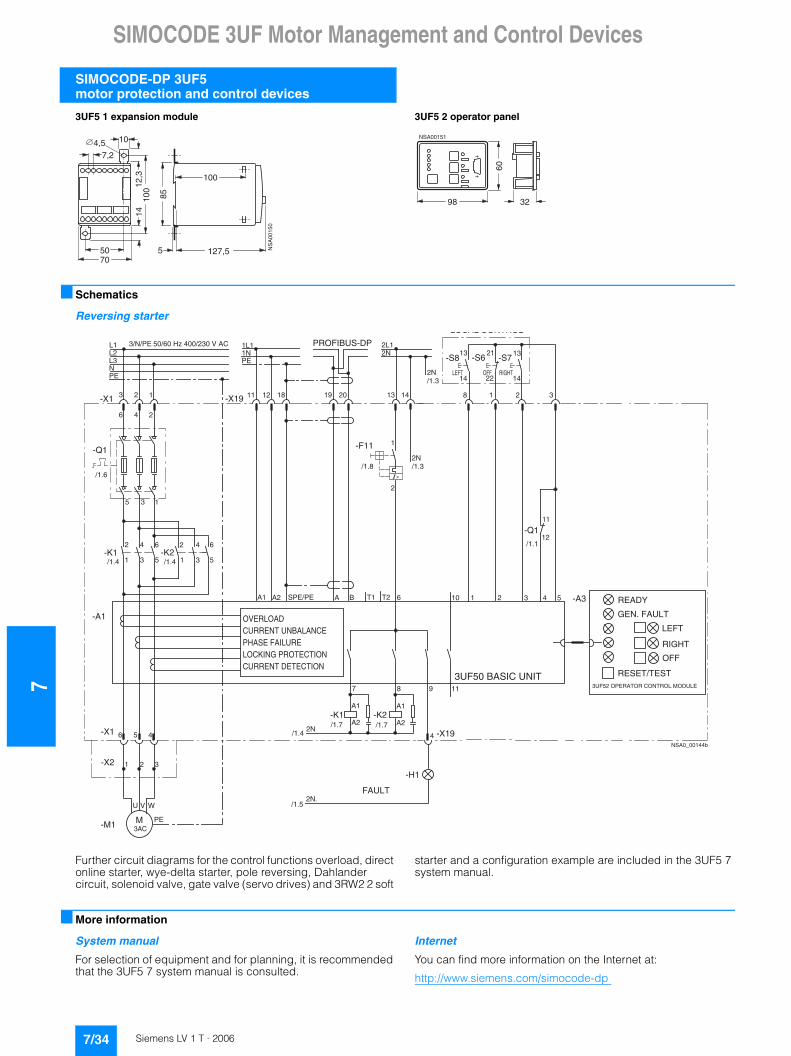
7SIMOCODE 3UF Motor Management and Control Devices
SIMOCODE-DP 3UF5motor protection and control devices
3UF5 1 expansion module 3UF5 2 operator panel
■ Schematics
Reversing starter
Further circuit diagrams for the control functions overload, direct online starter, wye-delta starter, pole reversing, Dahlander circuit, solenoid valve, gate valve (servo drives) and 3RW2 2 soft
starter and a configuration example are included in the 3UF5 7 system manual.
■ More information
System manual
For selection of equipment and for planning, it is recommended that the 3UF5 7 system manual is consulted.
Internet
You can find more information on the Internet at:
http://www.siemens.com/simocode-dp
5070
85
100
4,57,2
12,3
100
1410
127,5 NS
A00
150
5
60
3298
NSA00151
3AC
2L12N
A B
-Q111
12
NSA0_00144b
READY
GEN. FAULT
U V W
-M1
A1 A2 SPE/PE
5-K1 -K2
2 6
1
4
3
2
1
4
3
6
5
15 3
1L11NPE
L1L2L3NPE
M
3 2 1
6 4 2
-X1
-Q1
/1.6
/1.4 /1.4
11 12 18-X19 19 20
>
-F11
13
/1.8
1
2
14
/1.32N
/1.32N
T2 6T1
8 1 2
1313 21
2214
-S8 -S6 -S7
14
3
/1.1
1 2 3 4 5
118
10
-K2A1
A2
6 5 4
1 2 3
-X1
-X2
PE
-A1
9
/1.7
4
7
-K1A1
A2/1.72N
/1.4
2N./1.5
-X19
-H1
-A3
OVERLOADCURRENT UNBALANCEPHASE FAILURELOCKING PROTECTIONCURRENT DETECTION
3UF50 BASIC UNIT
FAULT
LEFT
RIGHT
OFF
RESET/TEST3UF52 OPERATOR CONTROL MODULE
LOCAL CONTROL
RIGHTOFFLEFT
PROFIBUS-DP3/N/PE 50/60 Hz 400/230 V AC
7/34 Siemens LV 1 T · 2006

SIMOCODE 3UF Motor Management and Control Devices
7
3UF18 current transformersfor overload protection
■ Overview
The 3UF1 8 current transformers are protection transformers and are used for actuating overload relays. Protection transformers are designed to ensure proportional current transfer up to a
multiple of the primary rated current. The 3UF18 current transformers convert the maximum current of the corresponding operating range into the standard signal 1 A secondary.
■ Technical specifications
1) With or without box terminal.
2) Conductor cross-sections for box terminals, see 3TF6 8 and 3TF6 9 contactors in the section Contactors and Contactor Assemblies.
3) With max. conductor cross-section, a terminal cover for maintaining the phase spacing is required.
Climatic environmental conditions
Temperatures• Operation °C -25 ... +60 • Storage/transport °C -40 ... +85
Temperature changes• Operation °C/h max. 10• Storage/transport °C/h max. 20
Relative humidity % 15 ... 95 (indoor, acc. to IEC 60721-3, no condensation)
Air pressure • Operation hPa 860 ... 1060 • Storage/transport hPa 650 ... 1060
Contaminants• SO2 ppm 0.5 (relative humidity ��60 %, no condensation) • H2S ppm 0.1 (relative humidity ��60 %, no condensation)
Mechanical environmental conditions
Vibrations (acc. to IEC 60068-2-6)
HzHz
10 ... 57 (for constant amplitude 0.15 nm)57 ... 150 (for constant acceleration 2 g)
Shock (acc. to IEC 60068-2-27) 12 shocks (half sine 15 g/11 ms)
Requirements acc. to IEC and DIN
Degree of protection (acc. to IEC 60529) IP20
Rated insulation voltage V 690/1000 (type-dependent)
Rating of the insulation (acc. to UL/CSA)
V 600
Trip class (acc. to IEC 60947-4-1) Suitable from CLASS 5 to CLASS 30
Power loss per conducting path of the transformers
Operating range for setting ...
to the lower limit to the upper limit
A mW (mVA) mW (mVA)• 3UF18 45 12.5 ... 50 33 (38) 570 (650)• 3UF18 48 25 ... 100 110 (120) 1700 (1900)• 3UF18 50 32 ... 130 135 (150) 2400 (2700)• 3UF18 52 50 ... 200 170 (190) 2600 (2900)• 3UF18 56 100 ... 400 450 (500) 6500 (7000)• 3UF18 57 125 ... 500 850 (940) 13000 (15000)• 3UF18 68-3F 160 ... 630 900 (1000) 17000 (19000)• 3UF18 68-3G 205 ... 820 1400 (1600) 22000 (25000)
Conductor cross-sections(one or two conductors connectable)
Current transformers
on second-ary side
on primary side
3UF18 45 3UF18 481) 3UF18 501) 3UF18 52 3UF18 563UF18 572)
3UF18 68-3FA002)
3UF18 68-3GA002)
• Terminal screw M 3.5 for connec-tion data see 3RT Contactors
for connec-tion data see 3RT Contactors
for connec-tion data see 3RT Contactors
M 8 M 10 M 10 M 12• Solid mm2 2 � 1.5 ... 2.5 -- -- -- --• Stranded mm2 2 � 1.5 ... 2.5 -- -- -- --• Finely stranded without end sleeve mm2 -- -- -- -- --• Finely stranded with end sleeve mm2 2 � 1.5 -- -- -- --• Finely stranded with cable lug mm2 -- 35 ... 95 50 ... 2403) 50 ... 240 185 ... 240• Stranded with cable lug mm2 -- 50 ... 120 70 ... 2403) 70 ... 240 185 ... 240• Connecting bars mm -- 20 � 4 25 � 6.30 �
630 � 5 50 � 5
• Tightening torque Nm 0.8 ... 1.4 10 ... 14 14 ... 24 14 ... 24 14 ... 24• Tightening torque lb 7 ... 12 89 ... 124 124 ... 210 124 ... 210 124 ... 210
7/35Siemens LV 1 T · 2006
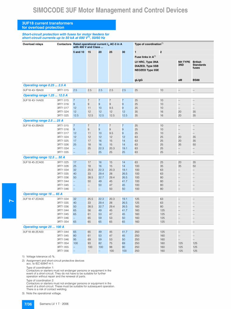
7SIMOCODE 3UF Motor Management and Control Devices
3UF18 current transformers for overload protection
Short-circuit protection with fuses for motor feeders for short-circuit currents up to 50 kA at 690 V1), 50/60 Hz
1) Voltage tolerance �5 %.
2) Assignment and short-circuit protective devices acc. to IEC 60947-4-1:
Type of coordination 1:Contactors or starters must not endanger persons or equipment in the event of a short-circuit. They do not have to be suitable for further operation without repair and the renewal of parts.
Type of coordination 2:Contactors or starters must not endanger persons or equipment in the event of a short-circuit. These must be suitable for subsequent operation. There is a risk of contact welding.
3) Note the operational voltage.
Overload relays Contactors Rated operational current Ie AC-3 in A with 400 V and Class ...
Type of coordination2)
5 and 10 15 20 25 30 1 2
Fuse links in A3)
LV HRC, Type 3NA
DIAZED, Type 5SB
NEOZED Type 5SE
gL/gG
NH TYPE 3ND
aM
British Standards fuses
BS88
Operating range 0.25 ... 2.5 A
3UF18 43-1BA00 3RT1 015 2.5 2.5 2.5 2.5 2.5 25 10 -- --
Operating range 1.25 ... 12.5 A
3UF18 43-1AA00 3RT1 015 7 7 7 7 7 25 10 -- --3RT1 016 9 9 9 9 9 25 10 -- --3RT1 017 12 11 10 9.5 9 25 10 -- --3RT1 024 12 12 12 12 12 35 16 20 353RT1 025 12.5 12.5 12.5 12.5 12.5 35 16 20 35
Operating range 2.5 ... 25 A
3UF18 43-2BA00 3RT1 015 7 7 7 7 7 25 10 -- --3RT1 016 9 9 9 9 9 25 10 -- --3RT1 017 12 11 10 9.5 9 25 10 -- --3RT1 024 12 12 12 12 12 63 25 20 353RT1 025 17 17 16 15 14 63 25 20 353RT1 026 25 18 16 15 14 63 25 35 503RT1 034 -- 25 22.3 20.3 19.1 63 25 -- --3RT1 035 -- -- 25 25 25 63 25 -- --
Operating range 12.5 ... 50 A
3UF18 45-2CA00 3RT1 025 17 17 16 15 14 63 25 20 353RT1 026 25 18 16 15 14 100 35 35 503RT1 034 32 25.5 22.3 20.3 19.1 100 63 -- --3RT1 035 40 33 29.4 28 26.5 100 63 -- --3RT1 036 50 38.5 32.7 29.4 26.5 100 80 -- --3RT1 044 -- 50 49 45 41.7 100 80 -- --3RT1 045 -- -- 50 47 45 100 80 -- --3RT1 046 -- -- -- 50 50 100 80 -- --
Operating range 16 ... 65 A
3UF18 47-2DA00 3RT1 034 32 25.5 22.3 20.3 19.1 125 63 -- --3RT1 035 40 33 29.4 28 26.5 125 63 -- --3RT1 036 50 38.5 32.7 29.4 26.5 160 80 -- --3RT1 044 65 56 49 45 41.7 160 125 -- --3RT1 045 65 61 53 47 45 160 125 -- --3RT1 046 -- 65 59 53 50 160 125 -- --3RT1 054 65 65 65 65 65 160 125 -- --
Operating range 25 ... 100 A
3UF18 48-2EA00 3RT1 044 65 65 49 45 41.7 250 125 -- --3RT1 045 80 61 53 47 45 250 160 -- --3RT1 046 95 69 59 53 50 250 160 -- --3RT1 054 100 93 82 75 69 250 160 125 1253RT1 055 -- 100 100 98 90 250 160 125 1253RT1 056 -- -- -- 100 100 250 160 125 125
7/36 Siemens LV 1 T · 2006

SIMOCODE 3UF Motor Management and Control Devices
7
3UF18 current transformersfor overload protection
1) Assignment and short-circuit protective devices acc. to IEC 60947-4-1:
Type of coordination 1:Contactors or starters must not endanger persons or equipment in the event of a short-circuit. They do not have to be suitable for further operation without repair and the renewal of parts.
Type of coordination 2:Contactors or starters must not endanger persons or equipment in the event of a short-circuit. These must be suitable for subsequent operation. There is a risk of contact welding.
2) Note the operational voltage.
Overload relays Contactors Rated operational current Ie AC-3 in A with 400 V and Class ...
Type of coordination1)
5 and 10 15 20 25 30 1 2
Fuse links in A2)
LV HRC, Type 3NA
DIAZED, Type 5SB
NEOZED Type 5SE
gL/gG
NH TYPE 3ND
aM
British Standards fuses
BS88
Operating range 32 ... 130 A
3UF18 50-3AA00 3RT1 044 65 56 49 45 41.7 250 125 -- --3RT1 045 80 61 53 47 45 250 160 -- --3RT1 046 95 69 59 53 50 250 160 -- --3RT1 054 115 93 82 75 69 315 224 160 1603RT1 055 130 122 107 98 90 315 224 160 1603RT1 056 -- 130 130 120 111 315 224 160 1603RT1 064 -- -- -- 130 130 315 224 160 160
Operating range 50 ... 200 A
3UF18 52-3BA00 3RT1 054 115 93 82 75 69 355 224 160 2003RT1 055 150 122 107 98 90 355 224 160 2003RT1 056 185 150 131 120 111 355 224 160 2003RT1 064 200 182 160 146 135 355 224 160 2003RT1 065 -- 200 188 172 159 355 224 160 2003RT1 066 -- -- 200 195 180 355 224 160 2003RT1 075 -- -- -- 200 200 355 224 160 200
Operating range 63 ... 250 A
3UF18 54-3CA00 3RT1 056 185 150 131 120 111 355 250 160 2003RT1 064 225 182 160 146 135 400 250 250 3553RT1 065 250 215 188 172 159 500 400 315 3553RT1 066 -- 243 213 195 180 500 400 315 3553RT1 075 -- 250 250 250 240 500 400 400 3553RT1 076 -- -- -- -- 250 500 400 400 355
Operating range 100 ... 400 A
3UF18 56-3DA00 3RT1 065 265 215 188 172 159 500 400 315 4003RT1 066 300 243 213 195 180 500 400 315 4003RT1 075 400 324 284 260 240 630 500 400 4503RT1 076 -- 400 355 325 300 630 500 500 4503TF6 8 -- -- 400 400 400 800 500 630 450
Operating range 125 ... 500 A
3UF18 57-3EA00 3RT1 066 300 243 213 195 180 500 400 315 4003RT1 075 400 324 284 260 240 800 500 400 4503RT1 076 500 405 355 325 300 800 500 500 4503TF6 8 -- 500 500 479 441 800 500 630 4503TF6 9 -- -- -- 500 500 800 500 630 450
Operating range 160 ... 630 A
3UF18 68-3FA00 3RT1 075 400 324 284 260 240 800 500 400 4503RT1 076 500 405 355 325 300 800 500 500 4503TF6 8 630 630 536 479 441 1000 500 630 4503TF6 9 -- -- -- 531 500 1000 500 630 450
Operating range 200 ... 820 A
3UF18 69-3GA00 3TF6 8 630 630 536 479 441 1000 500 630 4503TF6 9 820 662 572 531 500 1000 500 630 450
7/37Siemens LV 1 T · 2006

7SIMOCODE 3UF Motor Management and Control Devices
3UF18 current transformers for overload protection
■ Dimensional drawings
3UF18 43 current transformer
3UF18 45 current transformerfor stand-alone installation: for screw and snap-on mounting onto 35 mm standard mounting rails according to EN 50022
1) Clearance to grounded components.
2) Snap-on mounting onto standard mounting railsEN 50022-35 x 7.5 or EN 50022-35 x 15
3UF18 47 to 3UF18 52 current transformers
3UF1 854 to 3UF1 857 current transformers
��
�'
!�
& �
� �� �
����������
$ � �
�
!
�$
�
� % �
��
�
��
� � �
� � � � � � � � � $
�$
$ � �� �
$� ' � '
& �
& � % � ��
$
�'
a a
b
d e f
n
q
ml
hi
j6,2
k
g
NS
A0_
0015
7b
1
a b d e f g h i j k l m n q
26,5 25 82 111 122 10,5 90 46 90 105 35 62 89 Ø 6,2 26,5 25 82 111 122 10,5 90 46 90 105 35 62 89 Ø 6,2
37 37,5 71,5 99 114 15 110 41 120 95 33 67 98 Ø 6,6 42 37,5 71,5 102 122 20 110 42 120 95 33 67 98 Ø 9
3UF1 8473UF1 848
3UF1 8503UF1 852
3RT1 0443RT1 0453RT1 046
1 Additional cover, can be shortened1
Transformers Contactors
��(�����!$
� � �
� �
���
���
$�
$ $$ � �
� � !
� % �� �
� �
�
� � � � � � � � � � � � � � � � � � � � � � � � � �
� � � � � � � � � �
� � � � � � � � � � � � � � � � � �
� � � � � ) � & � � �
* ) � � + � � ) � ) +
� � � � � � �� � � � � � $� � � � � � !
7/38 Siemens LV 1 T · 2006
SIMOCODE 3UF Motor Management and Control Devices
7
3UF18 current transformersfor overload protection
3UF18 68-3FA00, 3UF18 68-3GA00 current transformersFor 3TF68 contactors
NSA0_001590,5
4015
170
230
74
230100
28
232
220
210
174
140
15
12
7070
105
c
a
b
gfe
d
12
a b c d e f g
390 398 30 5 145 175 420 410 408 40 8 155 195 450
14 for M 12
14 for M 12
Contactors
3TF683TF68
Transformers
3UF18 68-3FA003UF18 68-3GA00
7/39Siemens LV 1 T · 2006
7SIMOCODE 3UF Motor Management and Control Devices
3UL22 summation current transformers
■ Overview
The 3UL22 summation current transformers sense fault currents in machines and plants. Together with the 3UL21 evaluation unit
or the SIMOCODE 3UF motor management and control device they enable residual-current and ground-fault monitoring.
■ Technical specifications
■ Dimensional drawings
3UL22 summation current transformers
Summation current transformers
Type 3UL22 .1 3UL22 .2 3UL22 .3
Rated insulation voltage Ui AC50/60 Hz
690 V 1000 V
Rated fault current I�n• Without response delay A 0.3 ... 1 0.3 ... 40 0.3 ... 40• With response delay A 1 1 ... 40 1 ... 40
Permissible ambient temperatures °C -20 ... +70
Feed-through openings mm 40 65 120
For Protodur cablescan be fed through max. mm² 4 x 95 4 x 240 8 x 300
NSB00364
a1a2 a3
b5
b2
b3
a4
b1
b 4
a5
c 1 c 2
c 3
a 6
Z1
A2 Z3
Z2
3UL22 1-A3UL22 2-A3UL22 3-A 200
125100
1659575
201010
201515
200110
85
10097,572,580
100170 100
5542,5
107,57,5
1206540
857065
706050
554540
a1 a2 a3 a4 a5 a6 b1 b2 b3 b4 b5 c1 c2 c3Type
for M 4for M 4for M 4
7/40 Siemens LV 1 T · 2006

LOGO! Logic Modules
7
General data
■ Overview
• The compact, user-friendly, and low-cost solution for simple control tasks
• Compact, user-friendly, can be used universally without accessories
• "All in one": the display and operator panel are integrated• 36 different functions can be linked at a press of a button or
with PC software; up to 130 times in total• Functions can be changed simply using buttons;
no complicated rewiring
Catalog ST 70
Information on LOGO! can also be found in the catalog ST 70:
http://www.siemens.com/automation/simatic/ftp/st70/html_00/st70k1ad.pdf
■ Design
The LOGO! modular design is available in different variants for different supply voltages (12 V DC, 24 V DC, 24 V AC, 115/230 V DC, 115/230 V AC):• Basic variants• Low-cost pure variants without operator control and display
panels
The LOGO! variants have the following distinguishing characteristics:• R: Relay output• C: Clock/time switch• o: Without display
LOGO! is simple:• Warning and switching off in one unit; no other tools are
required• Non-volatile storage of control program and setpoints
(e.g. times) in integrated EEPROM
LOGO! is space-saving:• e.g. LOGO! 230RC: 72 x 90 x 55 mm (W x H x D)• Fitted mounting in the distribution box (same mounting
dimensions as the ground-fault circuit interrupter)
LOGO! offers maximum flexibility and is universal:• Expandability:
Depending on the application, additional expansion modules can be connected
LOGO! is communication-capable:• Optional communication modules support interfacing to
AS-Interface and instabus EIB networks
■ Function
LOGO! is simple:• 36 functions:
Integrated basic functions (e.g. AND, OR) and special functions (e.g. timers, counters, latching relays, PI controllers) of the electronics
• Program generation simply by combining stored functions at the press of a key or PC software
• Easy-to-use and simple duplication of the control program with an optional program module
LOGO! offers maximum flexibility and is universal:• Easy modification by reconnecting the functions at a press of
a key; no need for time-consuming rewiring• Optional operation from the PC:
For creating, simulating, online testing and archiving the control program on the PC, including documentation facility
7/41Siemens LV 1 T · 2006

7LOGO! Logic Modules
LOGO! Modular basic variants
■ Overview
• The space-saving basic variants• With interface for connection of expansion modules
■ Design
• Relay outputs with up to 10 A output signal(not LOGO! 24)
• Integrated front panel with background illumination (4x12 characters)
• Integrated operator control panel• Integrated EEPROM for storing control program and setpoints• Optional program module• Integrated clock with automatic summertime/wintertime
changeover (not LOGO! 24)• 8 digital inputs, 4 digital outputs• 2 inputs as analog inputs for 12/24 V DC variants
(0 to 10 V); inputs can also be used as digital inputs• 2 inputs for counting up to 2 kHz can be used
(for DC variants only)• Interface for connecting expansion modules, max. 24 digital
inputs, 16 digital outputs, 8 analog inputs and 2 analog outputs can be addressed
■ Function
• Integrated basic and special functions: - Basic functions:
AND, OR, NOT, NAND, NOR, XOR, positive/negative flank evaluation
- Special functions: ON delay, latching ON delay, OFF delay, pulse relay, latching relay, counter (forwards/backwards), time switch, interval time-delay relay, operating hours meter, threshold switch, asynchronous pulse encoder, twelve-month time switch, easy-to-use switch function, random generator, staircase lighting function according to DIN 18015-2, edge-triggered interval time-delay relay, combined ON/OFF delay, analog comparator, analog threshold switch, analog delta threshold switch, analog watchdog, analog amplifier, text and variable display, shift register, softkey function, PI controller, ramp function, analog multiplexer
• 130 function blocks can be combined• 24 flags (including start-up flag)• Integrated retentivity• Password protection
Optional function • Additional know-how protection with the optional program
module
7/42 Siemens LV 1 T · 2006
LOGO! Logic Modules
7
LOGO! Modular pure variants
■ Overview
• The cost-optimized basic variants• With integrated interface for connection of expansion modules
■ Design
• Relay outputs with up to 10 A output signal• Integrated EEPROM for storing control program and setpoints• Optional program module• Integrated clock with automatic summertime/wintertime
changeover (not LOGO! 24o)• 8 digital inputs, 4 digital outputs• 2 inputs as analog inputs for 12/24 V DC variants
(0 to 10 V); inputs can also be used as digital inputs• 2 inputs for counting up to 2 kHz can be used
(for DC variants only)• Interface for connecting expansion modules, max. 24 digital
inputs, 16 digital outputs, 8 analog inputs and 2 analog outputs can be addressed
■ Function
• Integrated basic and special functions: - Basic functions:
AND, OR, NOT, NAND, NOR, XOR, positive/negative flank evaluation
- Special functions: ON delay, latching ON delay, OFF delay, pulse relay, latching relay, counter (forwards/backwards), time switch, interval time-delay relay, operating hours meter, threshold switch, asynchronous pulse encoder, twelve-month time switch, easy-to-use switch function, random generator, staircase lighting function according to DIN 18015-2, edge-triggered interval time-delay relay, combined ON/OFF delay, analog comparator, analog threshold switch, analog delta threshold switch, analog watchdog, analog amplifier, shift register, softkey function, PI controller, ramp function, analog multiplexer
• 130 function blocks can be combined• 24 flags (including start-up flag)• Integrated retentivity• Password protection
Optional function • Additional know-how protection with the optional program
module
7/43Siemens LV 1 T · 2006

7LOGO! Logic Modules
LOGO! Software
■ Overview
• The user-friendly software for switchgear program generation on the PC
• Switchgear program generation for function diagrams (FBD) or contact diagrams (LAD)
• Additional testing, simulation, online testing and archiving of the switchgear programs
• Professional documentation with the help of various comment and print functions
■ Design
The connection between LOGO! and the PC is established with the help of the LOGO! PC cable (serial interface)
Minimum system requirements
Windows 98 SE, NT 4.0, ME, 2000 or XP• Pentium PC• 90 MB free on hard disk• 64 MB RAM• SVGA graphics card with minimum 800x600 resolution
(256 colors)
Mac OS X• PowerMac G3, G4, G4 Cube, iMac, PowerBook G3, G4 or
iBook
Linux (tested with Caldera OpenLinux 2.4)• Runs on all Linux releases on which Java 2 SDK Version 1.3.1
runs• Please consult your Linux release for hardware requirements
■ Function
• Control program generation with the programming languages FBD and LAD (switchable). How to place the functions on the drawing board by means of "Drag and Drop" is almost self-explanatory
• Comprehensive documentation functions: Various print options permit professional documentation
• Program simulation (offline): For preliminary text of switching programs on the PC
• Program test (online): The current values of LOGO! are presented on screen
• Comprehensive, context-sensitive online help functions
The following functions are available:• Basic functions (AND, OR, NOT, NAND, NOR, XOR, positive
edge evaluation, negative edge evaluation)• ON delay• OFF delay• Current impulse relay• Latching• Latching ON delay• Operating hours meter• Interval time-delay relay/pulse output mode• Up/down counter• Threshold switch• Pulse encoder• Twelve-month time switch• Time switch• ON/OFF delay• Random generator• Edge-triggered interval time-delay relay• Analog threshold switch• Analog comparator• Analog delta threshold switch• Analog watchdog• Analog amplifier• Staircase lighting switch• Easy-to-use switch• Message texts• Shift register• Softkey• PI controller• Ramp function• Analog multiplexer
7/44 Siemens LV 1 T · 2006
3RP, 7PV Timing Relays
7
General data
■ Function
3RP15/3RP20/7PV function table
1) Note on function with start contact: A new control signal at terminal B, after the operating time has started, resets the operating time to zero. This does not apply to G, G! and H, H!, which are not retriggerable.
2) This function is indicated on the unit with the identification letter C.
3) For the flashing function, the start between interval D and pulse Di is selectable.
4) This function is indicated on the unit with the identification letter H.
5) This function is indicated on the unit with the identification letter B.
Function Function chart 3RP20 timing re-lay and 3RP19 01 label set
3RP15 timing relay and3RP19 01 label set
7PV timing relay
Timing relay energized
Contact closed
Contact open
3RP
20 0
5-.A
3RP
20 2
5
3RP
15 0
5-.A
3RP
19 0
1-0A
Iden
tific
atio
n le
tter
3RP
15 1
.
3RP
15 2
5
3RP
15 2
7
3RP
15 3
.
3RP
15 4
0
3RP
15 5
5
3RP
15 7
.
7PV
33
1 CO contactON-delay 7 7 7 A 7 7 7
OFF-delaywith auxiliary voltage
7 7 B1)7 7
2)
OFF-delaywithout auxiliary voltage
7
ON-delay and OFF-delay with auxiliary voltage (t = ton = toff)
7 7 C1)
Flashing, starting with interval(pulse/interval 1:1)
7 7 D 73)
Clock-pulse, starting with interval(dead interval, pulse time, and time setting ranges each separately adjustable)
7
Passing make contact 7 7 E 74)
Passing break contact with auxiliary voltage
7 7 F1)
Pulse-forming with auxiliary voltage (pulse generation at the output does not depend on duration of energizing)
7 7 G1) 75)
Additive ON-delay with auxiliary voltage
7 7 H1)
1 NO contact (semiconductor)ON-delayThe two-wire timing relay is connec-ted in series with the load. Timing begins after application of the excit-ing voltage. The semiconductor output then becomes conducting, and the load is energized.
7
���������
���
����
����
A1/A2
15/1815/16
t
35 ms
NS
B00
859B1/A2
>
15/16
A1/A2
200 ms
t
15/18
NS
B00
860
>
tt
NS
B00
861
15/16
A1/A2
15/18
B1/A2
NS
B00
862
t t
15/16
A1/A2
15/18
������
���
����
����
�������� ������������
NS
B00
864
t
A1/A2
15/1815/16
t
NS
B00
865
35 ms>A1/A2
15/1815/16
B1/A2
t
NS
B00
867
>A1/A2
15/1815/16
B1/A2
35 ms
t
NS
B00
868
t1 t2t3
A1/A2
15/1815/16
B1/A2
�
����
��������
7/45Siemens LV 1 T · 2006

73RP, 7PV Timing Relays
General data
1) Note on function with start contact: A new control signal at terminal B, after the operating time has started, resets the operating time to zero. This does not apply to G, G! and H, H!, which are not retriggerable.
Function Function chart 3RP20 timing relay and 3RP19 01 label set
3RP15 timing relay and3RP19 01 label set
Timing relay energized
Contact closed
Contact open
3RP
20 0
5-.B
3RP
20 2
5
3RP
15 0
5-.B
3RP
19 0
1-0B
3RP
15 0
5-.R
3RP
19 0
1-0A
Iden
tific
atio
nle
tter
3RP
15 1
.
3RP
15 2
5
3RP
15 2
7
3RP
15 3
.
3RP
15 4
0
3RP
15 5
5
3RP
15 6
0
3RP
15 7
.
2 CO contactsON-delay 7 7 7 A 7
ON-delayand instantaneous contact
7 7 A!
OFF-delay with auxiliary voltage
7 7 7 B1)
OFF-delaywith auxiliary voltageand instantaneous contact
7 7 B!1)
OFF-delay without auxiliary voltage
7
ON-delay and OFF-delay with auxiliary voltage (t = ton = toff)
7 7 7 C1)
ON-delay and OFF-delay with auxiliary voltage and instantaneous contact (t = ton = toff)
7 7 C!1)
Flashing, starting with interval(pulse/interval 1:1)
7 7 7 D
Flashing, starting with interval(pulse/interval 1:1)and instantaneous contact
7 7 D!
Passing make contact 7 7 7 E
Passing make contactand instantaneous contact
7 7 E!
t
NS
B00
871
A1/A2
15/1815/16
25/2825/26
15/1815/16
t
A1/A2
NS
B00
872
21/2421/22
t
NS
B00
873
>A1/A2
15/1815/16
B1/A2
25/2825/26
35 ms
����
���
�
���
����
����
������ �����
����
!
15/16
A1/A2
200 ms
t
15/18
25/2825/26 N
SB
0087
5
>
15/1815/16
t
25/2825/26
A1/A2
B1/A2
t
NS
B00
876
15/1815/16
t21/2421/22
A1/A2
B1/A2
t
NS
B00
877
15/1815/16
t
A1/A2
25/2825/26
t
NS
B00
878
15/1815/16
21/2421/22
NS
B00
879A1/A2
t t
15/1815/16
t
A1/A2
25/2825/26
NS
B00
880
15/1815/16
21/2421/22
NS
B00
881A1/A2
t
7/46 Siemens LV 1 T · 2006
3RP, 7PV Timing Relays
7
General data
1) Note on function with start contact: A new control signal at terminal B, after the operating time has started, resets the operating time to zero. This does not apply to G, G! and H, H!, which are not retriggerable.
2) For function diagrams showing the various possibilities of operation of the 3RP15 60-1S.30 (see Page 7/48).
Function Function chart 3RP20 timing relay and3RP19 01 label set
3RP15 timing relay and3RP19 01 label set
Timing relay energized
Contact closed
Contact open
3RP
20 0
5-.B
3RP
20 2
5
3RP
15 0
5-.B
3RP
19 0
1-0B
3RP
15 0
5-.R
3RP
19 0
1-0A
Iden
tific
atio
nle
tter
3RP
15 1
.
3RP
15 2
5
3RP
15 2
7
3RP
15 3
.
3RP
15 4
0
3RP
15 5
5
3RP
15 6
0
3RP
15 7
.
2 CO contactsPassing break contact with auxiliary voltage
7 7 7 F1)
Passing break contact with auxiliary voltageand instantaneous contact
7 7 F!1)
Pulse-formingwith auxiliary voltage(pulse generation at the output does not depend on duration of energizing)
7 7 7 G1)
Pulse-formingwith auxiliary voltageand instantaneous contact(pulse generation at the output does not depend on duration of energizing)
7 7 G!1)
Additive ON-delay with auxiliary voltage
7 H1)
Additive ON-delay with auxiliary voltage and instantaneous contact
7 7 H!1)
Wye-delta function 7 7 *�
2 NO contactsWye-delta function *� 7
3 NO contactsWye-delta functionwith overtravel function2)
(idling)
7
15/1815/16
t
25/28
35ms
NS
B00
882
�
25/26
B1/A2
A1/A2
15/1815/16
t
35ms
21/2421/22
NS
B00
883A1/A2
B1/A2
>
15/1815/16
t
25/2825/26
A1/A2
B1/A2
35ms
NS
B00
884
�
15/1815/16
21/2421/22
A1/A2
B1/A2
t
NS
B00
885
35ms>
�������
�������
����
����
�������
�
�
� � ��
�����
����
�
� � � �� � � �
� � � � �
� � � �
� � � �
��� ��
�
t
A1/A2
50ms
17/18
27/28
NS
B00
888
t 50 ms
NS
B00
889A1/A2
17/1817/28
����
����
����
� ��
��������
�
� ��
� ��
�����"
7/47Siemens LV 1 T · 2006
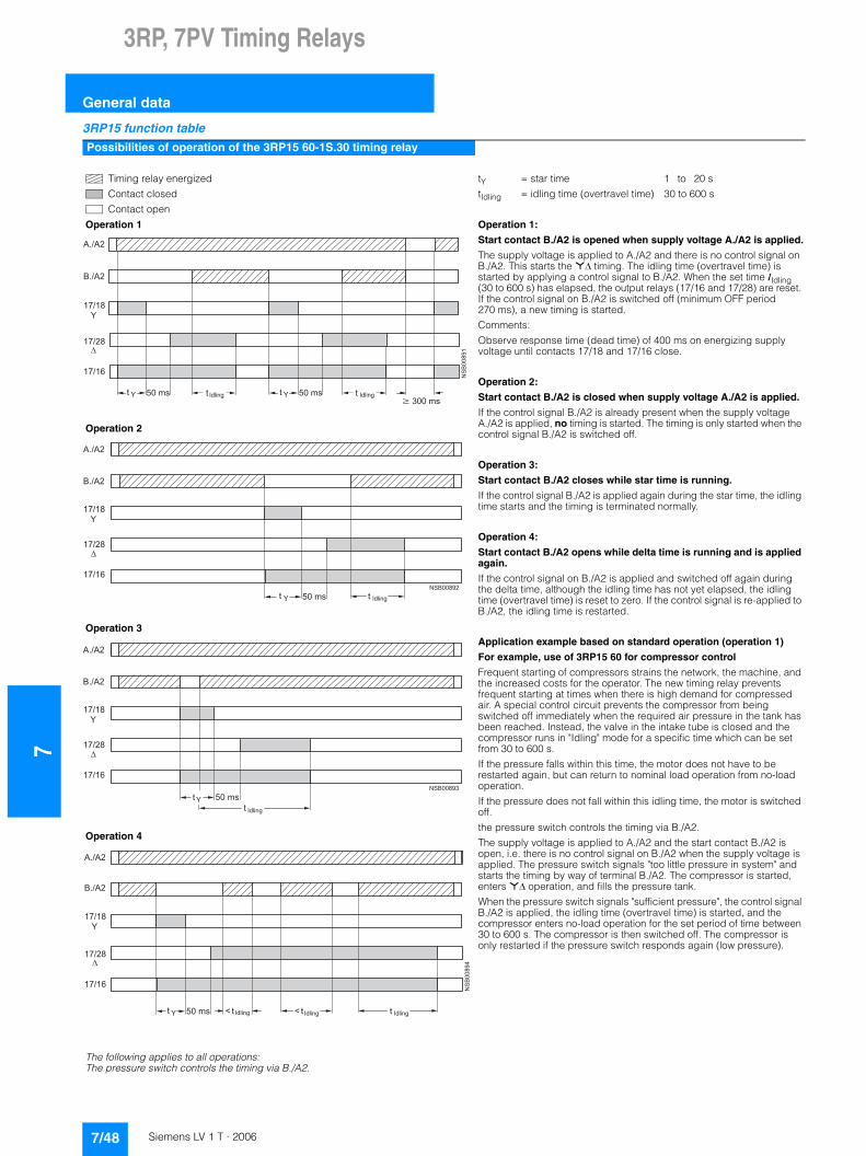
73RP, 7PV Timing Relays
General data
3RP15 function table
Possibilities of operation of the 3RP15 60-1S.30 timing relay
Timing relay energized
Contact closed
Contact open
tY = star time 1 to 20 s
tIdling = idling time (overtravel time) 30 to 600 s
Operation 1 Operation 1:
Start contact B./A2 is opened when supply voltage A./A2 is applied.
The supply voltage is applied to A./A2 and there is no control signal on B./A2. This starts the *� timing. The idling time (overtravel time) is started by applying a control signal to B./A2. When the set time IIdling (30 to 600 s) has elapsed, the output relays (17/16 and 17/28) are reset. If the control signal on B./A2 is switched off (minimum OFF period 270 ms), a new timing is started.
Comments:
Observe response time (dead time) of 400 ms on energizing supply voltage until contacts 17/18 and 17/16 close.
Operation 2:
Start contact B./A2 is closed when supply voltage A./A2 is applied.
If the control signal B./A2 is already present when the supply voltage A./A2 is applied, no timing is started. The timing is only started when the control signal B./A2 is switched off.
Operation 3:
Start contact B./A2 closes while star time is running.
If the control signal B./A2 is applied again during the star time, the idling time starts and the timing is terminated normally.
Operation 4:
Start contact B./A2 opens while delta time is running and is applied again.
If the control signal on B./A2 is applied and switched off again during the delta time, although the idling time has not yet elapsed, the idling time (overtravel time) is reset to zero. If the control signal is re-applied to B./A2, the idling time is restarted.
Application example based on standard operation (operation 1)
For example, use of 3RP15 60 for compressor control
Frequent starting of compressors strains the network, the machine, and the increased costs for the operator. The new timing relay prevents frequent starting at times when there is high demand for compressed air. A special control circuit prevents the compressor from being switched off immediately when the required air pressure in the tank has been reached. Instead, the valve in the intake tube is closed and the compressor runs in "Idling" mode for a specific time which can be set from 30 to 600 s.
If the pressure falls within this time, the motor does not have to be restarted again, but can return to nominal load operation from no-load operation.
If the pressure does not fall within this idling time, the motor is switched off.
the pressure switch controls the timing via B./A2.
The supply voltage is applied to A./A2 and the start contact B./A2 is open, i.e. there is no control signal on B./A2 when the supply voltage is applied. The pressure switch signals "too little pressure in system" and starts the timing by way of terminal B./A2. The compressor is started, enters *� operation, and fills the pressure tank.
When the pressure switch signals "sufficient pressure", the control signal B./A2 is applied, the idling time (overtravel time) is started, and the compressor enters no-load operation for the set period of time between 30 to 600 s. The compressor is then switched off. The compressor is only restarted if the pressure switch responds again (low pressure).
Operation 2
Operation 3
Operation 4
The following applies to all operations: The pressure switch controls the timing via B./A2.
��������
�#��
�#��
� �����$
� ��
� �
$ �����"�� ����� $� ����� �����"� �����
�#��
�#��
� ����$
� ��
� �
$
��������
����� � �����"�
�#��
�#��
� ����$
� ��
� �
$
�������
������ �����"
�
��������
�#��
�#��
� �����$
� ��
� �
$ �����"�6� �����"�6 �����"������
7/48 Siemens LV 1 T · 2006
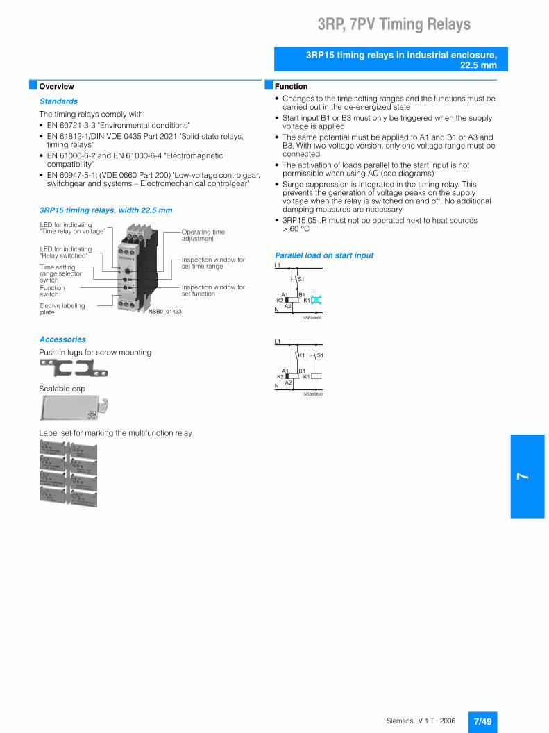
3RP, 7PV Timing Relays
7
3RP15 timing relays in industrial enclosure,22.5 mm
■ Overview
Standards
The timing relays comply with: • EN 60721-3-3 "Environmental conditions"• EN 61812-1/DIN VDE 0435 Part 2021 "Solid-state relays,
timing relays"• EN 61000-6-2 and EN 61000-6-4 "Electromagnetic
compatibility"• EN 60947-5-1; (VDE 0660 Part 200) "Low-voltage controlgear,
switchgear and systems – Electromechanical controlgear"
3RP15 timing relays, width 22.5 mm
Accessories
Push-in lugs for screw mounting
�
Sealable cap
�
Label set for marking the multifunction relay
�
■ Function
• Changes to the time setting ranges and the functions must be carried out in the de-energized state
• Start input B1 or B3 must only be triggered when the supply voltage is applied
• The same potential must be applied to A1 and B1 or A3 and B3. With two-voltage version, only one voltage range must be connected
• The activation of loads parallel to the start input is not permissible when using AC (see diagrams)
• Surge suppression is integrated in the timing relay. This prevents the generation of voltage peaks on the supply voltage when the relay is switched on and off. No additional damping measures are necessary
• 3RP15 05-.R must not be operated next to heat sources > 60 °C
Parallel load on start input
�
�
����+�����
������������ ������������������� ����
������������ ������������ ����
������� ������������ ����� ����� ����� ��
����������������� �
����� ��� ������� ��
���� ������������� � ��������
���� ������������� ���� ��
L1
S1
K2A1
A2K1
NNSB00895
B1
8�
9���
��9�
�
�������
��9�
��
7/49Siemens LV 1 T · 2006
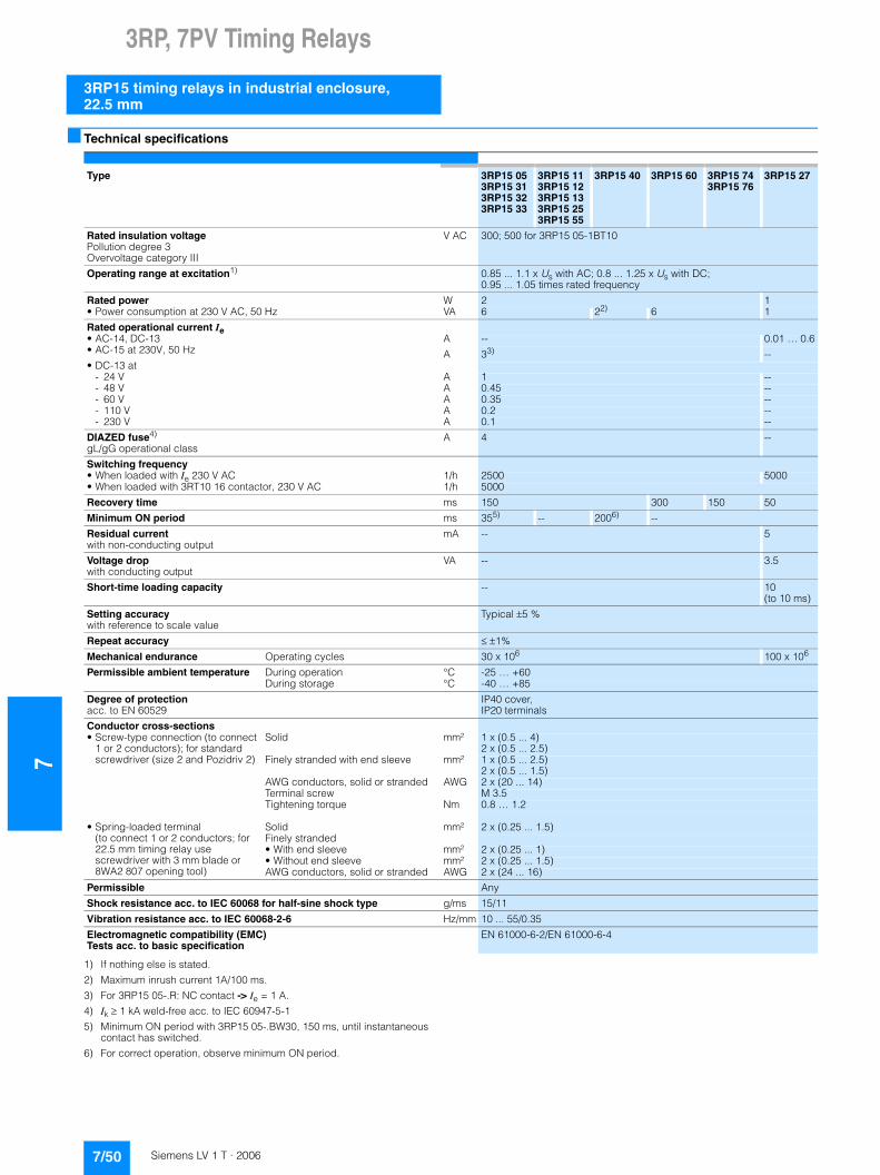
73RP, 7PV Timing Relays
3RP15 timing relays in industrial enclosure,22.5 mm
■ Technical specifications
1) If nothing else is stated.
2) Maximum inrush current 1A/100 ms.
3) For 3RP15 05-.R: NC contact -> Ie = 1 A.
4) Ik � 1 kA weld-free acc. to IEC 60947-5-1
5) Minimum ON period with 3RP15 05-.BW30, 150 ms, until instantaneous contact has switched.
6) For correct operation, observe minimum ON period.
Type 3RP15 053RP15 313RP15 323RP15 33
3RP15 113RP15 123RP15 133RP15 253RP15 55
3RP15 40 3RP15 60 3RP15 743RP15 76
3RP15 27
Rated insulation voltage Pollution degree 3Overvoltage category III
V AC 300; 500 for 3RP15 05-1BT10
Operating range at excitation1) 0.85 ... 1.1 x Us with AC; 0.8 ... 1.25 x Us with DC; 0.95 ... 1.05 times rated frequency
Rated power W 2 1• Power consumption at 230 V AC, 50 Hz VA 6 22) 6 1
Rated operational current Ie • AC-14, DC-13 A -- 0.01 … 0.6• AC-15 at 230V, 50 Hz A 33) --• DC-13 at
- 24 V A 1 --- 48 V A 0.45 --- 60 V A 0.35 --- 110 V A 0.2 --- 230 V A 0.1 --
DIAZED fuse4) gL/gG operational class
A 4 --
Switching frequency • When loaded with Ie 230 V AC 1/h 2500 5000• When loaded with 3RT10 16 contactor, 230 V AC 1/h 5000
Recovery time ms 150 300 150 50
Minimum ON period ms 355) -- 2006) --
Residual current with non-conducting output
mA -- 5
Voltage drop with conducting output
VA -- 3.5
Short-time loading capacity -- 10 (to 10 ms)
Setting accuracy with reference to scale value
Typical �5 %
Repeat accuracy � �1%
Mechanical endurance Operating cycles 30 x 106 100 x 106
Permissible ambient temperature During operation °C -25 … +60During storage °C -40 … +85
Degree of protection acc. to EN 60529
IP40 cover, IP20 terminals
Conductor cross-sections • Screw-type connection (to connect
1 or 2 conductors); for standard screwdriver (size 2 and Pozidriv 2)
Solid mm² 1 x (0.5 ... 4) 2 x (0.5 ... 2.5)
Finely stranded with end sleeve mm² 1 x (0.5 ... 2.5) 2 x (0.5 ... 1.5)
AWG conductors, solid or stranded AWG 2 x (20 ... 14)Terminal screw M 3.5Tightening torque Nm 0.8 … 1.2
• Spring-loaded terminal (to connect 1 or 2 conductors; for 22.5 mm timing relay use screwdriver with 3 mm blade or 8WA2 807 opening tool)
Solid mm² 2 x (0.25 ... 1.5)Finely stranded• With end sleeve mm² 2 x (0.25 ... 1)• Without end sleeve mm² 2 x (0.25 ... 1.5)AWG conductors, solid or stranded AWG 2 x (24 ... 16)
Permissible Any
Shock resistance acc. to IEC 60068 for half-sine shock type g/ms 15/11
Vibration resistance acc. to IEC 60068-2-6 Hz/mm 10 ... 55/0.35
Electromagnetic compatibility (EMC)Tests acc. to basic specification
EN 61000-6-2/EN 61000-6-4
7/50 Siemens LV 1 T · 2006
3RP, 7PV Timing Relays
7
3RP15 timing relays in industrial enclosure,22.5 mm
■ Dimensional drawings
■ Schematics
3RP15 internal schematics (terminal designation to DIN 46199, Part 5)
NSB0_01606
A B C74
86536
62 90
1522,5
62 110
1522,5
82
A B C
Type 3RP15 13RP15 25-.A3RP15 273RP15 10-A3RP15 553RP15 7
3RP15 053RP15 25-.B3RP15 33RP15 40-.B3RP15 60
Removable terminal
Spring-loaded terminal 84 94 103
Screw-type terminal 83 92 102
3RP15 05-.A3RP15 1.3RP15 25-.A
3RP15 05-.A3RP15 3.-.A
3RP15 05-.A 3RP15 05-.A
ON-delay OFF-delaywith auxiliary voltage
ON-delay and OFF-delaywith auxiliary voltage
Flashing
3RP15 05-.A 3RP15 05-.A 3RP15 05-.A 3RP15 05-.A
Passing make contact Passing break contact with auxiliary voltage
Pulse-formingwith auxiliary voltage
Additive ON-delay with auxiliary voltage
� ��
�� �� �������
�
��
�:7:��'
�:����� '�:������'
��������
�:7:��'
�:����� '�:������'
�� ��
�� ���
� �� �
��������
�:7:��'
�:����� '�:������'
�� ��
�� ���
� �� � � ��
�� �� ��������
�
��
�:7:��'
�:����� '�:������'
=
A3 15
A2 18 NS
B00
901
16
A1
AC/DC24V
AC100/127VAC200/240V
��������
�:7:��'
�:����� '�:������'
��
��
� �� � ��
��� �������
�:7:��'
�:����� '�:������'
��
��
� �� � ��
��� ��������
�:7:��'
�:����� '�:������'
�� ��
�� ���
� �� �
�
7/51Siemens LV 1 T · 2006
73RP, 7PV Timing Relays
3RP15 timing relays in industrial enclosure,22.5 mm
3RP15 27
U = 24 ... 66 V AC/DC90 ... 240 V AC/DC
3RP15 40-.A 3RP15 55 3RP15 05-.AW30
ON-delay, two-wire design
OFF-delaywithout auxiliary voltage
Clock-pulse relay Multi-function relay(same functions as 3RP15 05-1A)
3RP15 05-.B, 3RP15 25-1B 3RP15 05-.B 3RP15 05-.B 3RP15 05-.B
ON-delay, 3RP15 25-1Balso for 42...48/60 V AC/DC (see page 8/13 3RP15 25-1BR30)
OFF-delay with auxiliary voltage ON-delay and OFF-delaywith auxiliary voltage
Flashing
3RP15 05-.B 3RP15 05-.B 3RP15 05-.B 3RP15 05-.B
Passing make contact Passing break contact with auxiliary voltage
Pulse-forming with auxiliary voltage Additive ON-delay with auxiliary voltage and instantaneous contact
3RP15 05-.B 3RP15 05-.B 3RP15 05-.B 3RP15 05-.B
ON-delay and instantaneous contact
OFF-delay with auxiliary voltageand instantaneous contact
ON-delay and OFF-delay with auxiliary voltage and instantaneous contact
Flashing and instantaneous contact
3RP15 05-.B 3RP15 05-.B 3RP15 05-.B 3RP15 05-.B
Passing make contactand instantaneous contact
Passing break contact with auxiliary voltage and instantaneous contact
Pulse-forming with auxiliary voltageand instantaneous contact
Wye-delta function
��>
�� ��������
�
�:7:�����/'�:7:���/���'
8���
��
�� �� �������
�
��
�:7:����� '�:7:������'
�:7:��'
��
�� �� �������
�
��
�:����� '�:������'
=
�:7:�'
�
�:7:��'�:7:��'###��'
�� ��
�� ���
��
�:7:��###���'
��������
� ��
�� ���
��
�:7:��'
�:����� '�:������'
��
�� ��������
� ��������
�:7:��'
�:����� '�:������'
�� ��
�� �
� �� �
��
��
��� ��������
�:7:��'
�:����� '�:������'
�� ��
�� �
� �� �
��
��
���
� ��
�� ���
��
�:7:��'
�:����� '�:������'
��
�� ��������
�
==
� ��
�� �� �������
�
��
�:7:��'
�:����� '�:������'
��
��� ��������
�:7:��'
�:����� '�:������'
��
��
� �� � ��
���
��
��� ��������
�:7:��'
�:����� '�:������'
��
��
� �� � ��
���
��
��� �������
�:7:��'
�:����� '�:������'
�� ��
�� ���
� �� �
�
��
����
� ��
�� ���
��
�:7:��'
�:����� '�:������'
��
�� �������
�� ��������
�:7:��'
�:����� '�:������'
�� ��
�� �
� �� �
��
��
���� ��������
�:7:��'
�:����� '�:������'
�� ��
�� �
� �� �
��
��
����
� ��
�� ���
��
�:7:��'
�:����� '�:������'
��
�� ��������
��
=
� ��
�� �� ��������
�
��
�:7:��'
�:����� '�:������'
��
���� ��������
�:7:��'
�:����� '�:������'
��
��
� �� � ��
���
��
���� �������
�:7:��'
�:����� '�:������'
��
��
� �� � ��
���
��
����
�
$���� ��������
� ��
�:7:��'
�:����� '�:������'
���
�
7/52 Siemens LV 1 T · 2006
3RP, 7PV Timing Relays
7
3RP15 timing relays in industrial enclosure,22.5 mm
Position of the connection terminals
Note: All the diagrams show the view onto the connection terminals.1) Depending on the version.
3RP15 05-.BW30/-1BT20/-.RW30 3RP15 25-. BR30 3RP15 25-. BW30 3RP15 40-.B
Multi-function relay(for functions see function table)
ON-delay ON-delay OFF-delay without auxiliary voltage
3RP15 60-. S 3RP15 7.-.M20 3RP15 74, 3RP15 76
Wye-delta timing relay with overtravel function (idling)
Wye-delta timing relay Wye-delta timing relay
����������
� � � � � � � � �
�
�
� �
� �
� �
� � � � � � � � � � � �
� � � �
� � � � � � � �
� � � � � �
�� ��
�� ����
��
����������
�����
��
�� ��
��
��
��
��
��
����
�����������
��
�� ��
��
��
���
��
��
��
� � � �
� � � � ������
� �
� �
� �� �
� � � � � � � � � � �� � � � � � � � � �
� � � � � � � �
� �
� �
���������
�
� �� � ��
�����������������
��� � ��
�������
� �
� � �� � �������
� � �
� � � � � � �
� � � � � � � �
� � �
��
����� ������
��
��������
������ ��������
���
3RP15 05-.A
.
3RP15 05-.AA40 3RP15 05-.AW 3RP15 05-.BP/-.BQ 3RP15 05-.BW 3RP15 05-1BT
� � � � � �
� � � �
� � � � � � � � � � � �
� � � �� � � � � � � � � �
� � � � � � �
A1 B1 15
16 18 A2NSB0_01605
for 2changeover contact
�� �� ��
�� �� ������
For 1 COcontact
�� ��
�� ��
�� �� ������
�� ��
�� �� ��
�� ��
�� ��
For 2 COcontacts
�� ��
�� �� �������
�� ��
�� �� ��
�� ��
�� ��
For 2 COcontacts
�� ��
�� �� �������
�� ��
�� �� ��
�� ��
�� ��
For 2 COcontacts
3RP15 05-.RW 3RP15 1. 3RP15 25-1A. or -1B.1) 3RP15 27 3RP15 3.
3RP15 40 3RP15 55 3RP15 60 3RP15 7.
�� �� ��
�� �� �����
��
�� ��
For 2 COcontacts
�� �� ��
�� �� ������
For 1 COcontact
�� ��
�� �� ��
��
�� ��
�� �� ��
�� �� ������
��
For 1 COcontact
For 2 COcontacts
��
������
For 1 NOcontact
� � � � � �
� � � �
� � � � � � � � � � � �
� � � �� � � � � � � � � �
� � � � � � �
� � � �
� � � � � �
� �
� � � �
� � � �
� � � � � �
� � � � � � � � �
� �
� �
� � � �
� � � � � � � � � �
� � � � � � �
� � � �
� � � � � � � � � �
� � � � � � � �
�� �� ��
�� �� ��������
For 1 COcontact
�� ��
�� �� ��
��
�
������
�� �
For 1 NOcontact
�� �� ��
�� �� ��������
For 1 NOcontact
7/53Siemens LV 1 T · 2006

73RP, 7PV Timing Relays
3RP15 timing relays in industrial enclosure,22.5 mm
3RP15 circuit diagrams
The contact element 17/18 is only closed in the star stage; the contact element is open in the delta stage as well as in the de-energized state.
Control circuits (example circuits) with 3RP15 74 and 3RP15 76 wye-delta timing relays
Control circuit (example circuit) with 3RP15 60 wye-delta timing relays
For pushbutton operation For maintained-contact operation
Size S00 to S3 Size S00 to S3
�
������
������
������
��
�
������������������
�� �� ��
�� �� ���� ��
�� ���� ��
�� ��
�� �� ���� �� ��
�� �� ��
�� �
��
��
�� ����
Legend:S0 button "OFF"S1 button "ON"S maintained-contact buttonK1 line contactorK2 star contactorK3 delta contactorK4 timer or timing relayF0 fuseF1 overload relayP1 pressure switch
�
����
�������
��
��
������
������
��
��
��
��
��
��
�
�
���
������������������
��
����
�� ��
��
��
��
��
��
�� ����
��
� �
� �
� �� �
� � � � � � � �
�
� � � � � �
� � � � � �
� �
� �
� �
� �
� � �
� � � � � � � � � � � � � � � � � �
� �
� �� �
� � � �
� �
� �
� �
� �
� �
� � � �� �
� �
�
� �
� �
� �
� �
� �
7/54 Siemens LV 1 T · 2006
3RP, 7PV Timing Relays
7
3RP20 timing relays, 45 mm
■ Overview
Standards
The timing relays comply with: • EN 60721-3-3 "Environmental conditions"• EN 61812-1/DIN VDE 0435 Part 2021 "Solid-state relays,
timing relays"• EN 61000-6-2 and EN 61000-6-4 "Electromagnetic
compatibility"• EN 60947-5-1; (VDE 0660 Part 200) "Low-voltage controlgear,
switchgear and systems – Electromechanical controlgear"• EN 61140 "Safe electrical isolation"
3RP20 timing relay, width 45 mm
Accessories
Label set for marking the multifunction relay
�
■ Function
• Changes to the time setting ranges and the functions must be carried out in the de-energized state
• Start input B1 or B3 must only be triggered when the supply voltage is applied
• The same potential must be applied to A1 and B1 or A3 and B3. With two-voltage version, only one voltage range must be connected
• The activation of loads parallel to the start input is not permissible when using AC (see diagrams)
• Surge suppression is integrated in the timing relay. This prevents the generation of voltage peaks on the supply voltage when the relay is switched on and off. No additional damping measures are necessary
Timing relay with multifunction
The functions can be adjusted by means of rotary switches. Indicator labels can be used to adjust different functions of the 3RP20 05 timing relay clearly and unmistakably.
The corresponding labels can be ordered as an accessory. The same potential must be applied to terminals A. and B..
3RP20 05 with one changeover contact
Corresponds to the functions of 3RP15 05-.A.
3RP20 05 with two changeover contacts
Corresponds to the functions of 3RP15 05-.B.
Parallel load on start input
�
�
������������ ���������������!�� ��"��� #
������������ ������������ ����"���� #
������� ������������ ����� ��
����������������� �
��� ����� ��
������� ����������� ��$�����
����+�����
L1
S1
K2A1
A2K1
NNSB00895
B1
��
����
����
�
�����
����
��
7/55Siemens LV 1 T · 2006
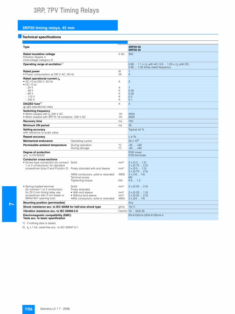
73RP, 7PV Timing Relays
3RP20 timing relays, 45 mm
■ Technical specifications
1) If nothing else is stated.
2) Ik � 1 kA, weld-free acc. to IEC 60947-5-1.
Type 3RP20 053RP20 25
Rated insulation voltage Pollution degree 3Overvoltage category III
V AC 300
Operating range at excitation1) 0.85 ... 1.1 x Us with AC; 0.8 ... 1.25 x Us with DC; 0.95 ... 1.05 times rated frequency
Rated power W 1• Power consumption at 230 V AC, 50 Hz VA 4
Rated operational current Ie • AC-15 at 230 V, 50 Hz A 3• DC-13 at
- 24 V A 1- 48 V A 0.45- 60 V A 0.35- 110 V A 0.2- 230 V A 0.1
DIAZED fuse2) gL/gG operational class
A 4
Switching frequency • When loaded with Ie 230 V AC 1/h 2500• When loaded with 3RT10 16 contactor, 230 V AC 1/h 5000
Recovery time ms 150
Minimum ON period ms 35
Setting accuracy with reference to scale value
Typical �5 %
Repeat accuracy � �1%
Mechanical endurance Operating cycles 30 x 106
Permissible ambient temperature During operation °C -25 … +60During storage °C -40 … +85
Degree of protection acc. to EN 60529
IP40 cover, IP20 terminals
Conductor cross-sections • Screw-type connection (to connect
1 or 2 conductors); for standard screwdriver (size 2 and Pozidriv 2)
Solid mm² 2 x (0.5 ... 1.5) 2 x (0.75 ... 2.5)
Finely stranded with end sleeve mm² 2 x (0.5 ... 1.5) 2 x (0.75 ... 2.5)
AWG conductors, solid or stranded AWG 2 x (18 ... 14)Terminal screw M3Tightening torque Nm 0.8 … 1.2
• Spring-loaded terminal(to connect 1 or 2 conductors; for 22.5 mm timing relay use screwdriver with 3 mm blade or 8WA2 807 opening tool)
Solid mm² 2 x (0.25 ... 2.5)Finely stranded• With end sleeve mm² 2 x (0.25 ... 1.5)• Without end sleeve mm² 2 x (0.25 ... 2.5)AWG conductors, solid or stranded AWG 2 x (24 ... 14)
Mounting position (permissible) Any
Shock resistance acc. to IEC 60068 for half-sine shock type g/ms 15/11
Vibration resistance acc. to IEC 60068-2-6 Hz/mm 10 ... 55/0.35
Electromagnetic compatibility (EMC) Tests acc. to basic specification
EN 61000-6-2/EN 61000-6-4
7/56 Siemens LV 1 T · 2006

3RP, 7PV Timing Relays
7
3RP20 timing relays, 45 mm
■ Dimensional drawings
■ Schematics
3RP20 internal schematics (terminal designation to DIN 46199, Part 5)
Position of the connection terminals
Note: All the diagrams show the view onto the connection terminals.
�
� � � � � � �
�
� � �����
��
�
�
�
3RP20 053RP20 25
3RP20 05 3RP20 05 3RP20 05
ON-delay OFF-delaywith auxiliary voltage
ON-delay and OFF-delaywith auxiliary voltage
Flashing
3RP20 05 3RP20 05 3RP20 05
Passing make contact Passing break contact with auxiliary voltage
Pulse-formingwith auxiliary voltage
� ��
�� � �����
��
��
��������
���������������
����
��������
���������������
�� ��
�� ���
� �� �
�����
��������
���������������
�� ��
�� ���
� �� � � ��
�� � ����
��
��
��������
���������������
-
A3 15
A2 18 NS
B00
901
16
A1
AC/DC24V
AC100/127VAC200/240V
�����
��������
���������������
��
��
� �� � ��
��� ����
��������
���������������
��
��
� �� � ��
���
3RP20 05-.A 3RP20 25-.A 3RP20 05-.BW30
� � � � � � � � �
�
� � � �
� � �
� �� � � � � � � � �
�
� � � �
� � �
� �
�����
��������
���������
��
��������� ����� �
7/57Siemens LV 1 T · 2006

73RP, 7PV Timing Relays
7PV timing relays for panel mounting
■ Technical specifications
■ Dimensional drawings
7PV33
LZX:MT78750 socket accessory, for 7PV33
7PX9921 socket accessory with rear connection
Type 7PV33 48
Rated insulation voltageOvervoltage category C to DIN VDE 0110
V AC 250
Operating range of excitation +10 ... -15 %
Rated power W 1• Power consumption at 230 V AC, 50 Hz VA 11
Rated operational currents Ie AC-1 at AC 230 V, 50 Hz
A 8
Switching frequency • When loaded with Ie 230 V AC 1/h 600• When loaded with 3RT16 contactor, AC 230 V 1/h --
Recovery time ms 50
Minimum ON period ms 50
Setting accuracy ��0.03 %• With reference to upper limit of scale ��10 ms
Repeat accuracy ��0.03 %��10 ms
Mechanical endurance Operating cycles 5 x 10⁶
Permissible ambient temperature During operation °C -10 ... +60During storage °C -30 ... +70
Degree of protection acc. to EN 60529
IP65
Permissible mounting positions Any
�����
���� ����
��
��
�������
������
�
���������
������������������ ��!!���������"" #������$��$�
%��"��&��������"�$����'
#�!�������'�!���(
� �
��
� � � � � � � �
� � � �
�
� � �
����
���
47
33
47
47
20,5 7
NSB01124a
7/58 Siemens LV 1 T · 2006
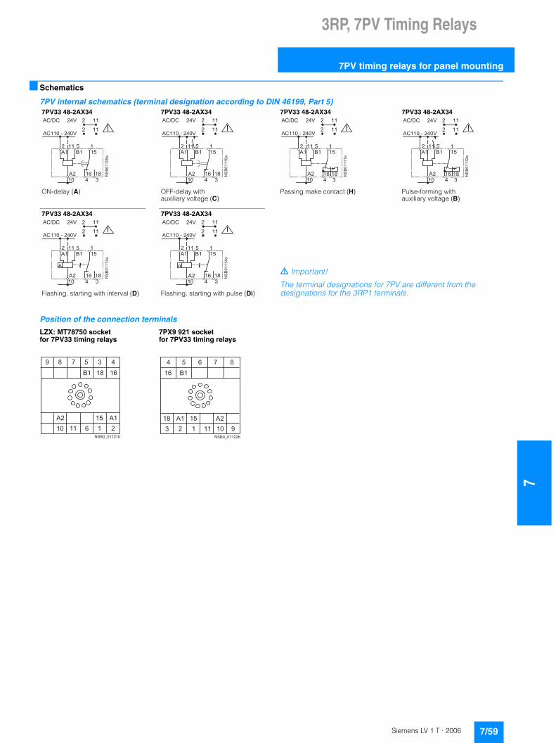
3RP, 7PV Timing Relays
7
7PV timing relays for panel mounting
■ Schematics
7PV internal schematics (terminal designation according to DIN 46199, Part 5)
Position of the connection terminals
7PV33 48-2AX34 7PV33 48-2AX34 7PV33 48-2AX34 7PV33 48-2AX34
ON-delay (A) OFF-delay with auxiliary voltage (C)
Passing make contact (H) Pulse-forming with auxiliary voltage (B)
7PV33 48-2AX34 7PV33 48-2AX34
. Important!
The terminal designations for 7PV are different from the designations for the 3RP1 terminals.Flashing, starting with interval (D) Flashing, starting with pulse (Di)
LZX: MT78750 socket for 7PV33 timing relays
7PX9 921 socket for 7PV33 timing relays
��
�������
������� ��
������� ���
�� ��
� ����
��
��
��
�� �
�� � �
�
��
�������
������� ��
������� ���
�� ��
� ����
��
��
��
�� �
�� � �
�
��
�������
������� ��
������� ���
�� ��
� ����
��
��
��
�� �
�� � �
�
��
����� �
������� ��
������� ���
�� ��
� ����
��
��
��
�� �
�� � �
�
��
�������
������� ��
������� ���
�� ��
� ����
��
��
��
�� �
�� � �
�
�
��
�������
������� ��
������� ���
�� ��
� ����
��
��
��
�� �
�� � �
�
�
� � �
� � � �� � � � � � � � �
� �
� �
� � � � �
� � � � � �
� � �
� � � � � � � �
� �
� � � � � �
� � � �
� � � � � � �
7/59Siemens LV 1 T · 2006
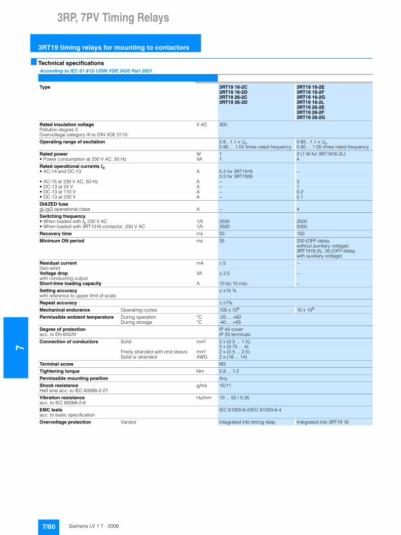
73RP, 7PV Timing Relays
3RT19 timing relays for mounting to contactors
■ Technical specifications
According to IEC 61 812-1/DIN VDE 0435 Part 2021
Type 3RT19 16-2C3RT19 16-2D3RT19 26-2C3RT19 26-2D
3RT19 16-2E3RT19 16-2F3RT19 16-2G3RT19 16-2L3RT19 26-2E3RT19 26-2F3RT19 26-2G
Rated insulation voltage Pollution degree 3Overvoltage category III to DIN VDE 0110
V AC 300
Operating range of excitation 0.8...1.1 x Us,0.95 ... 1.05 times rated frequency
0.85...1.1 x Us,0.95 ... 1.05 times rated frequency
Rated power W 1 2 (1 W for 3RT1916-2L)• Power consumption at 230 V AC, 50 Hz VA 1 4
Rated operational currents Ie • AC-14 and DC-13 A 0.3 for 3RT1916
0.5 for 3RT1926--
• AC-15 at 230 V AC, 50 Hz A -- 3• DC-13 at 24 V A -- 1• DC-13 at 110 V A -- 0.2• DC-13 at 230 V A -- 0.1
DIAZED fuse gL/gG operational class A -- 4
Switching frequency • When loaded with Ie 230 V AC 1/h 2500 2500• When loaded with 3RT1016 contactor, 230 V AC 1/h 2500 5000
Recovery time ms 50 150
Minimum ON period ms 35 200 (OFF-delay, without auxiliary voltage)3RT1916-2L: 35 (OFF-delay, with auxiliary voltage)
Residual current (two-wire)
mA � 5 --
Voltage drop with conducting output
VA � 3.5 --
Short-time loading capacity A 10 (to 10 ms) --
Setting accuracy with reference to upper limit of scale
� �15 %
Repeat accuracy ���1%
Mechanical endurance Operating cycles 100 x 106 10 x 106
Permissible ambient temperature During operation °C -25 ... +60During storage °C -40 ... +85
Degree of protection acc. to EN 60529
IP 40 coverIP 20 terminals
Connection of conductors Solid mm² 2 x (0.5 ... 1.5), 2 x (0.75 ... 4)
Finely stranded with end sleeve mm² 2 x (0.5 ... 2.5)Solid or stranded AWG 2 x (18 ... 14)
Terminal screw M3
Tightening torque Nm 0.8 ... 1.2
Permissible mounting position Any
Shock resistanceHalf sine acc. to IEC 60068-2-27
g/ms 15/11
Vibration resistance acc. to IEC 60068-2-6
Hz/mm 10 ... 55 / 0.35
EMC testsacc. to basic specification
IEC 61000-6-2/IEC 61000-6-4
Overvoltage protection Varistor Integrated into timing relay Integrated into 3RT19 16
7/60 Siemens LV 1 T · 2006

3RP, 7PV Timing Relays
7
3RT19 timing relays for mounting to contactors
■ Dimensional drawings
3RT19 16-2E, -2F, -2G, -2L solid-state time-delay auxiliary switch blocksfor size S00 contactors and contactor relays
3RT19 26-2E, -2F, -2G for size S0 to S3 contactors and contactor relays
3RT19 16-2C solid-state time-delay blocks, ON-delay for mounting onto the front of size S00 contactors
3RT19 26-2C mountable on top or bottom of the contactors for size S0 to S3
3RT19 16-2D solid-state time-delay blocks, OFF-delayfor mounting onto the front of size S00 contactors
3RT19 26-2D mountable on top or bottom of the contactors for size S0 to S3
NS
B00
985
38
5 9
4575
38
NS
B00
986 25
533
73
4646
12
NS
B00
987
3845
38
66
NS
B00
988
441
506
45
40
NS
B00
989
16 38
389 545
456 11 4
4150
26
NS
B00
990
7/61Siemens LV 1 T · 2006
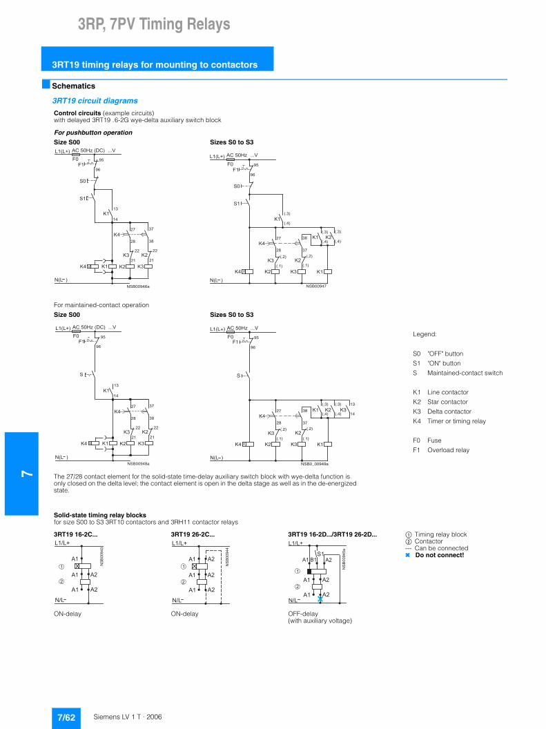
73RP, 7PV Timing Relays
3RT19 timing relays for mounting to contactors
■ Schematics
3RT19 circuit diagrams
Control circuits (example circuits) with delayed 3RT19 .6-2G wye-delta auxiliary switch block
For pushbutton operation
Size S00 Sizes S0 to S3
For maintained-contact operation
Size S00 Sizes S0 to S3
Legend:
S0
S1
S
K1
K2
K3
K4
F0
F1
"OFF" button
"ON" button
Maintained-contact switch
Line contactor
Star contactor
Delta contactor
Timer or timing relay
Fuse
Overload relay
The 27/28 contact element for the solid-state time-delay auxiliary switch block with wye-delta function is only closed on the delta level; the contact element is open in the delta stage as well as in the de-energized state.
��
�� ����
������
��
�
������
������
��
��
��
��
��
��
��
��
���
������������������
��
����
�� ��
��
����
��
������
������
�
������
������
����
����
�� ��
��
����
��
��
��
���
�������������
�� ��
��
����
����
����
����
����
����
����
����
����
��
�� ����
������
�
������
������
��
����
�
���
������������������
����
��
�� ��
��
����
��
��
��
��
F0
K1K3K2
NSB0_00949a
95
N(L )
L1(L+)
(.4)
(.3)
K1 K2
K4
K2K3
S
F196
AC 50Hz ...V
28 37
38
K427
(.4)
(.3)
(.1)
(.2)
(.1)
(.2)
K314
13
Solid-state timing relay blocksfor size S00 to S3 3RT10 contactors and 3RH11 contactor relays
3RT19 16-2C... 3RT19 26-2C... 3RT19 16-2D.../3RT19 26-2D... $ Timing relay block% Contactor--- Can be connected✖ Do not connect!
ON-delay ON-delay OFF-delay(with auxiliary voltage)
�4�
������
��4��
��
��
�
�
��
��
��
�4�
������
��4��
��
��
��
��
��
���
�
�4�
������
��4��
������ �
��
��
��
��
�
�
7/62 Siemens LV 1 T · 2006
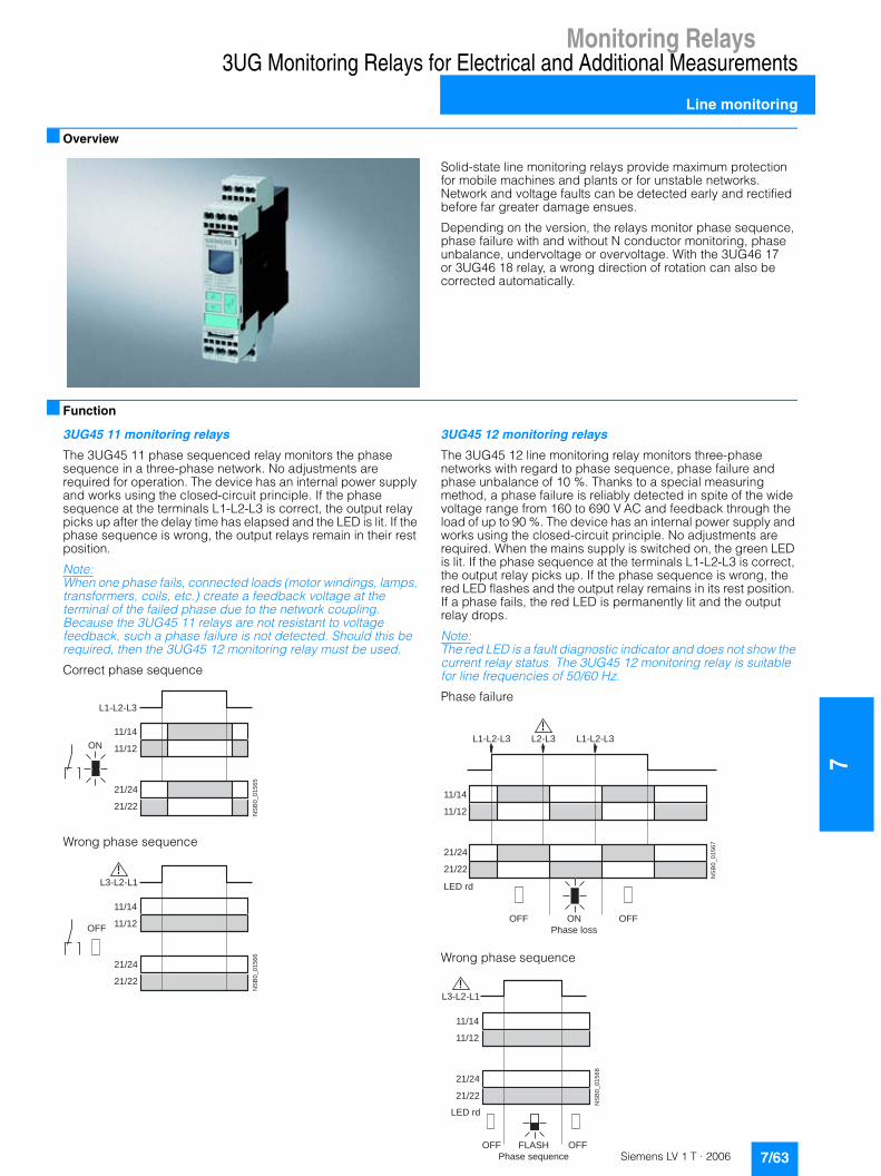
Monitoring Relays
7
3UG Monitoring Relays for Electrical and Additional Measurements
Line monitoring
7/63Siemens LV 1 T · 2006
■ Overview
Solid-state line monitoring relays provide maximum protection for mobile machines and plants or for unstable networks. Network and voltage faults can be detected early and rectified before far greater damage ensues.
Depending on the version, the relays monitor phase sequence, phase failure with and without N conductor monitoring, phase unbalance, undervoltage or overvoltage. With the 3UG46 17 or 3UG46 18 relay, a wrong direction of rotation can also be corrected automatically.
■ Function
3UG45 11 monitoring relays
The 3UG45 11 phase sequenced relay monitors the phase sequence in a three-phase network. No adjustments are required for operation. The device has an internal power supply and works using the closed-circuit principle. If the phase sequence at the terminals L1-L2-L3 is correct, the output relay picks up after the delay time has elapsed and the LED is lit. If the phase sequence is wrong, the output relays remain in their rest position.
Note:When one phase fails, connected loads (motor windings, lamps, transformers, coils, etc.) create a feedback voltage at the terminal of the failed phase due to the network coupling. Because the 3UG45 11 relays are not resistant to voltage feedback, such a phase failure is not detected. Should this be required, then the 3UG45 12 monitoring relay must be used.
Correct phase sequence
Wrong phase sequence
3UG45 12 monitoring relays
The 3UG45 12 line monitoring relay monitors three-phase networks with regard to phase sequence, phase failure and phase unbalance of 10 %. Thanks to a special measuring method, a phase failure is reliably detected in spite of the wide voltage range from 160 to 690 V AC and feedback through the load of up to 90 %. The device has an internal power supply and works using the closed-circuit principle. No adjustments are required. When the mains supply is switched on, the green LED is lit. If the phase sequence at the terminals L1-L2-L3 is correct, the output relay picks up. If the phase sequence is wrong, the red LED flashes and the output relay remains in its rest position. If a phase fails, the red LED is permanently lit and the output relay drops.
Note: The red LED is a fault diagnostic indicator and does not show the current relay status. The 3UG45 12 monitoring relay is suitable for line frequencies of 50/60 Hz.
Phase failure
Wrong phase sequence
NS
B0
_0
15
65
11/14
L1-L2-L3
11/12
21/24
21/22
ON
NS
B0
_0
15
66
11/14
L3-L2-L1
11/12
21/24
21/22
OFF
NS
B0
_0
15
67
11/14
L1-L2-L3L2-L3L1-L2-L3
11/12
21/24
21/22
LED rd
OFF OFFON
Phase loss
NS
B0
_0
15
68
11/14
11/12
L3-L2-L1
21/24
21/22
LED rd
FLASH
Phase sequence
OFFOFF

7Monitoring Relays
3UG Monitoring Relays for Electrical and Additional Measurements
Line monitoring
7/64 Siemens LV 1 T · 2006
3UG45 13 monitoring relays
The 3UG45 13 line monitoring relay monitors three-phase networks with regard to phase sequence, phase failure, phase unbalance of 20 % and undervoltage. The device has an internal power supply and works using the closed-circuit principle. The hysteresis is 5 %. The integrated response delay time is adjustable from 0 to 20 s and responds to undervoltage. If the direction is incorrect, the device switches off immediately. Thanks to a special measuring method, a phase failure is reliably detected in spite of the wide voltage range from 160 to 690 V AC and feedback through the load of up to 80 %. When the mains supply is switched on, the green LED is lit. If the phase sequence at the terminals L1-L2-L3 is correct, the output relay picks up. If the phase sequence is wrong, the red LED flashes and the output relay remains in its rest position. If a phase fails, the red LED is permanently lit and the output relay drops.
Note: The red LED is a fault diagnostic indicator and does not show the current relay status. The 3UG45 13 monitoring relay is suitable for line frequencies of 50/60 Hz.
Phase failure and undervoltage
Wrong phase sequence
3UG46 14 monitoring relays
The 3UG46 14 line monitoring relay has a wide voltage range and an internal power supply. The device is equipped with a display and is parameterized using three buttons. It monitors three-phase networks with regard to phase unbalance from 5 to 20 %, phase failure, undervoltage and phase sequence. The hysteresis is adjustable from 1 to 20 V. In addition, the device has a response delay and ON delay from 0 to 20 s in each case. The integrated response delay time responds to phase unbalance and undervoltage. If the direction is incorrect, the device switches off immediately. Thanks to a special measuring method, a phase failure is reliably detected in spite of the wide voltage range from 160 to 690 V AC and feedback through the load.
The 3UG46 14 monitoring relay can be operated on the basis of either the open-circuit or closed-circuit principle and with manual or auto RESET.
With the closed-circuit principle selected
Wrong phase sequence
Phase failure
Undervoltage
Unbalance
NSB0_01569
11/14
-20%
L1-L2-L3L2-L3L1-L2-L3
n3~U5%
11/12
21/24
21/22
LED rd
Delay
OFFOFF OFF
Hysteresis
ON
Phase loss
ON
NS
B0_01570
11/14
L3-L2-L1
11/12
21/24
21/22
LED rd
FLASH
Phase sequence
OFFOFF
NS
B0_01571
11/14
L3-L2-L1
11/12
21/24
21/22
NS
B0_01576
11/14
11/12
21/24
21/22
L1-L2-L3L2-L3L1-L2-L3
NS
B0_01577
<
21/24
21/22
11/14
11/12
x-yHysteresis
DelayonDelay
NS
B0_01578
> Asy
0%
21/24
21/22
11/14
11/12
Hysteresis
2%
DelayonDelay

Monitoring Relays
7
3UG Monitoring Relays for Electrical and Additional Measurements
Line monitoring
3UG46 15/3UG46 16 monitoring relays
The 3UG46 15/3UG46 16 line monitoring relay has a wide voltage range and an internal power supply. The device is equipped with a display and is parameterized using three buttons. The 3UG46 15 device monitors three-phase networks with regard to phase failure, undervoltage, overvoltage and phase sequence. The 3UG46 16 monitoring relay monitors the neutral conductor as well. The hysteresis is adjustable from 1 to 20 V. In addition the device has two separately adjustable delay times for overvoltage and undervoltage from 0 to 20 s in each case. If the direction is incorrect, the device switches off immediately. Thanks to a special measuring method, a phase failure is reliably detected in spite of the wide voltage range from 160 to 690 V AC and feedback through the load of up to 80 %.
The 3UG46 15/3UG46 16 monitoring relay can be operated on the basis of either the open-circuit or closed-circuit principle and with manual or auto RESET.
With the closed-circuit principle selected
Wrong phase sequence
Phase failure
Undervoltage
Overvoltage
3UG46 17/3UG46 18 monitoring relays
The 3UG46 17/ 3UG46 18 line monitoring relay has an internal power supply and can automatically correct a wrong direction of rotation. Thanks to a special measuring method, a phase failure is reliably detected in spite of the wide voltage range from 160 to 690 V AC and feedback through the load of up to 80 %. The device is equipped with a display and is parameterized using three buttons. The 3UG46 17 line monitoring relay monitors three-phase networks with regard to phase sequence, phase failure, phase unbalance, undervoltage and overvoltage. The 3UG46 18 monitoring relay monitors the neutral conductor as well. The hysteresis is adjustable from 1 to 20 V. In addition the device has delay times from 0 to 20 s in each case. The times respond to overvoltage, undervoltage, phase failure and phase unbalance. The 3UG46 17/3UG46 18 monitoring relay can be operated on the basis of either the open-circuit or closed-circuit principle and with manual or auto RESET.
The one changeover contact is used for warning or switching off in the event of line faults (voltage, unbalance), the other responds only to a wrong phase sequence. In conjunction with a contactor reversing assembly it is thus possible to change the direction automatically.
With the closed-circuit principle selected
Phase failure
Undervoltage
Overvoltage
Unbalance
NS
B0_01571
11/14
L3-L2-L1
11/12
21/24
21/22
NS
B0_01572
11/14
11/12
21/24
21/22
L1-L2-L3
L1-L2-L3-N
L2-L3
L1-L2-L3
L1-L2-L3
L1-L2-L3-N
NS
B0_01573
<
21/24
21/22
11/14
11/12
x-yHysteresis
Delay
NS
B0_01574
>
x-y
21/24
21/22
11/14
11/12
Hysteresis
Delay
NS
B0
_0
15
87
11/14
50 ms
11/12
21/24
21/22
L1-L2-L3
L1-L2-L3-N
L2-L3
L1-L2-L3
L1-L2-L3
L1-L2-L3-N
NS
B0_01588
11/14
50 ms
11/12
21/24
21/22
<x-yHysteresis
Delay
NS
B0
_0
15
89
11/14
50 ms
11/12
21/24
21/22
>
x-yHysteresis
Delay
NS
B0
_0
15
90
11/14
50 ms
11/12
21/24
21/22
> Asy
0 %
Hysteresis
2 %
Delay
7/65Siemens LV 1 T · 2006

7Monitoring Relays
3UG Monitoring Relays for Electrical and Additional Measurements
Line monitoring
■ Technical specifications
1) Note: This is a Class A product. In the household environment this device may cause radio interference. In this case the user must introduce suitable measures.
3UG45 11-..N20
3UG45 11-..P20
3UG45 11-..Q20
3UG45 12 3UG45 13 3UG46 14 3UG46 153UG46 163UG46 173UG46 18
General dataRated control supply voltage Us V 160 … 260 320 … 500 420 … 690 160 … 690
Rated frequency Hz 50/60
Rated output, typical• At 230 V AC W/VA 2/4 -- -- 2/2.5• At 400 V AC W/VA -- 2/8 -- 2/3.5• At 460 V AC W/VA -- -- 2/8 2/4
Width mm 22.5
RESET -- automatic/manual
Function principle Closed-circuit Closed-circuit, open-circuit (3UG46 17/3UG46 18: closed-circuit)
Availability time after application of Us ms 200 1000
Response time on occurrence of a fault ms 300
Adjustable tripping delay time s -- 0.1 ... 20
Adjustable ON-delay time s -- 0.1 … 20 --
Mains buffering time, typical ms 10 30
Rated insulation voltage UiDegree of pollution 3Overvoltage category III acc. to VDE 0110
V 690
Rated impulse withstand voltage kV 6
Permissible ambient temperature • During operation °C -25 … +60• During storage °C -40 … +85
EMC tests1) IEC 60947-1/IEC 61000-6-2/IEC 61000-6-4
Degree of protection• Enclosures IP40• Terminals IP20
Vibration resistance acc. to IEC 60068-2-6 Hz/mm 1-6/15; 6-500, 20 m/s2
Shock resistance acc. to IEC 60068 Part 2-27 g/ms 15/11
Conductor cross-section• Screw-type connection M 3 (standard screwdriver size 2 and Pozidriv 2)
- Solid mm2 1 x (0.5 ... 4)/2 x (0.5 ... 2.5)- Finely stranded with end sleeve mm2 1 x (0.5 ... 2.5)/2 x (0.5 ... 1.5)- AWG conductors, solid or stranded AWG 2 x (20 ... 14)- Tightening torque Nm 0.8 … 1.2
• Spring-loaded terminals- Solid mm2 2 x (0.25 ... 1.5)- Finely stranded, with end sleeves acc. to DIN 46228 mm2 2 x (0.25 ... 1.5)- Finely stranded mm2 2 x (0.25 ... 1.5)- AWG conductors, solid or stranded AWG 2 x (24 ... 16)
Measuring circuitsMeasuring range V 160 ... 260 320 ... 500 420 ... 690 160 ... 690
Setting range V 200...690 160...690
Measuring accuracy % -- ±5
Repeat accuracy at constant parameters % -- ±1
Setting accuracy -- �10 % referred to upper limit of effective range
�1 V
Accuracy of digital display -- ±1 digit
Deviations for temperature deviations %/°C -- ±0.1
Hysteresis for voltage V -- 5 % of upper limit of effective range
1 ... 20 V
Hysteresis for unbalance % -- 2 % of limit value
2 % of limit value for 3UG46 17/3UG46 18
Deviation for frequency fluctuation % -- ±1 %
7/66 Siemens LV 1 T · 2006
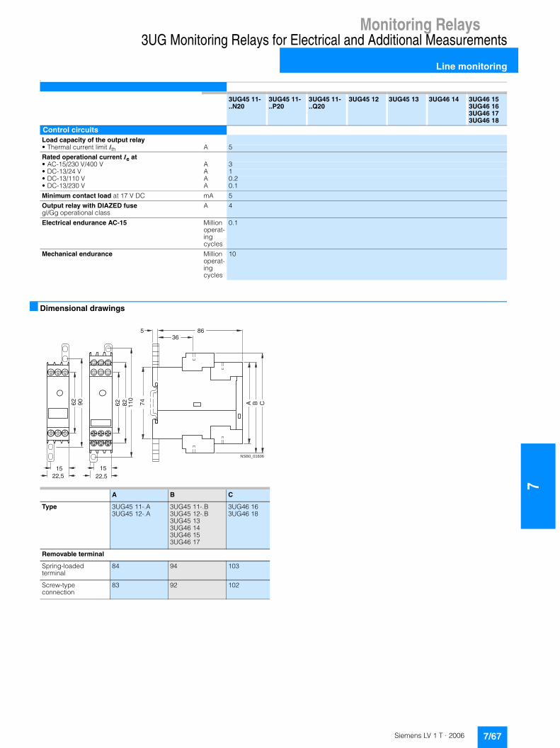
Monitoring Relays
7
3UG Monitoring Relays for Electrical and Additional Measurements
Line monitoring
k■ Dimensional drawings
3UG45 11-..N20
3UG45 11-..P20
3UG45 11-..Q20
3UG45 12 3UG45 13 3UG46 14 3UG46 153UG46 163UG46 173UG46 18
Control circuitsLoad capacity of the output relay• Thermal current limit Ith A 5
Rated operational current Ie at• AC-15/230 V/400 V A 3• DC-13/24 V A 1• DC-13/110 V A 0.2• DC-13/230 V A 0.1
Minimum contact load at 17 V DC mA 5
Output relay with DIAZED fusegl/Gg operational class
A 4
Electrical endurance AC-15 Million operat-ing cycles
0.1
Mechanical endurance Million operat-ing cycles
10
NSB0_01606
A B C74
86536
62 90
1522,5
62 110
1522,5
82
A B C
Type 3UG45 11-.A3UG45 12-.A
3UG45 11-.B3UG45 12-.B3UG45 133UG46 143UG46 153UG46 17
3UG46 163UG46 18
Removable terminal
Spring-loaded terminal
84 94 103
Screw-type connection
83 92 102
7/67Siemens LV 1 T · 2006
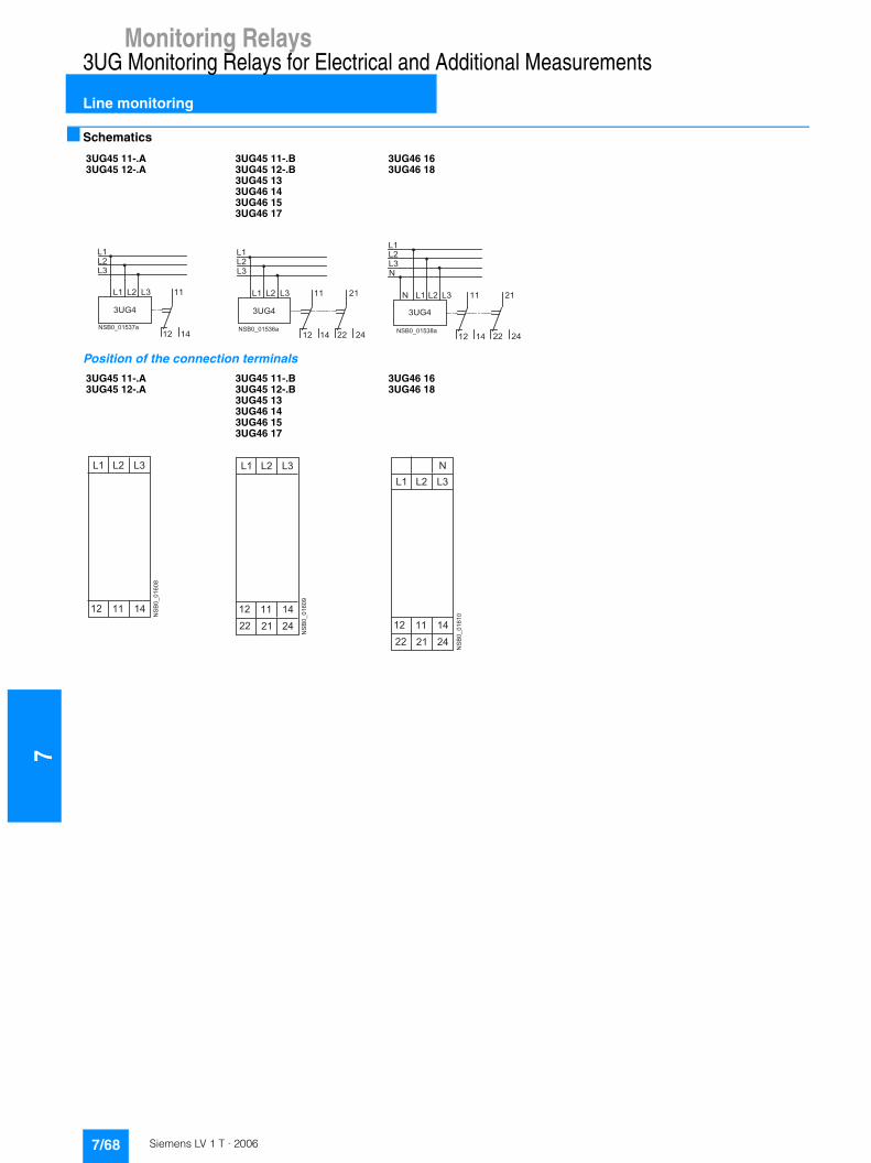
7Monitoring Relays
3UG Monitoring Relays for Electrical and Additional Measurements
Line monitoring
■ Schematics
Position of the connection terminals
3UG45 11-.A3UG45 12-.A
3UG45 11-.B3UG45 12-.B3UG45 133UG46 143UG46 153UG46 17
3UG46 163UG46 18
� � � � � � � � �
� �
� �
� �
�
� � � �
� �� �
� �
� � �
� � � � � � � � � �
� �
� �
� �
�
� � � �
� �� �
� �
� �
� �
�
� � �
� � � � � � � � � �
� �
� �
� �
�
� � � �
� �� �
� �
� �
� �
�
�
�
� � �
3UG45 11-.A3UG45 12-.A
3UG45 11-.B3UG45 12-.B3UG45 133UG46 143UG46 153UG46 17
3UG46 163UG46 18
����������
� �
� � � � �
� � � �
����������
� �
� � � � �
� � � �
� � � � �
����������
� �
� � � � �
� � � �
� � � � �
�
7/68 Siemens LV 1 T · 2006
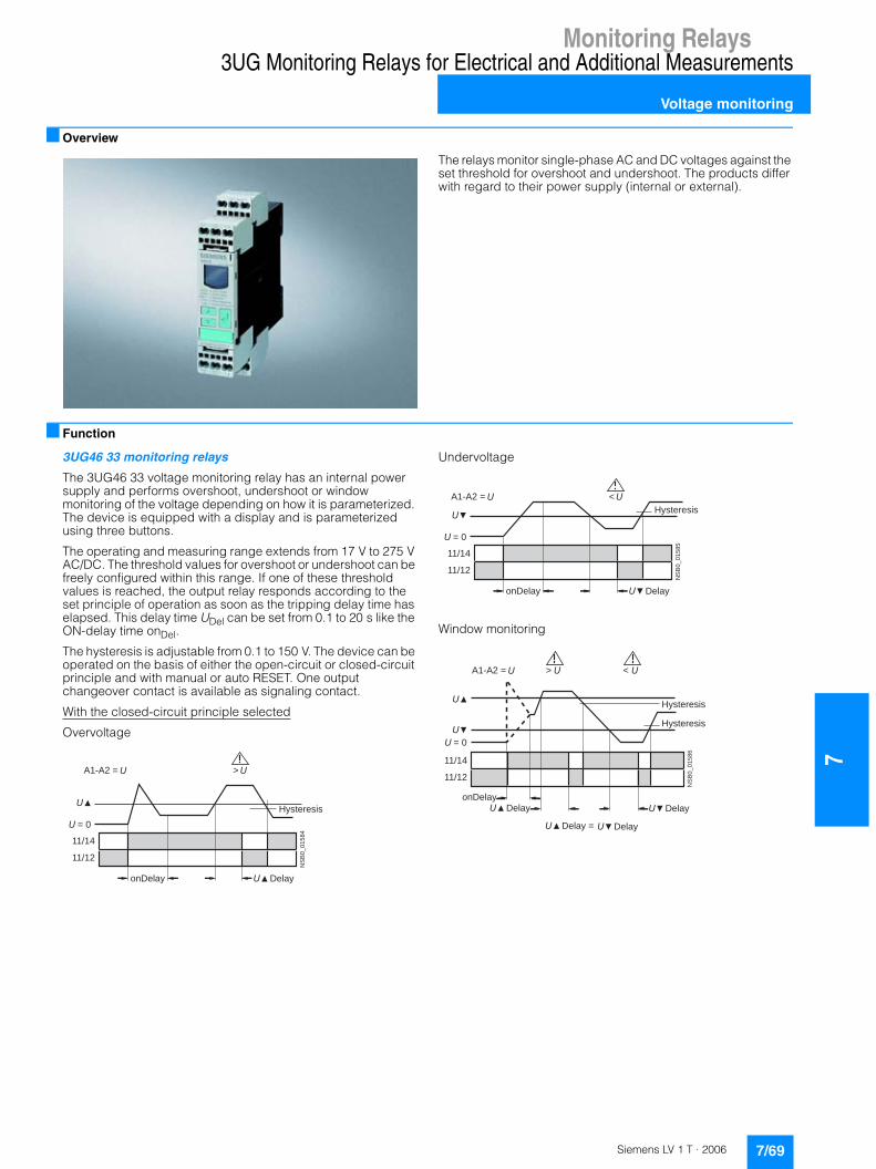
Monitoring Relays
7
3UG Monitoring Relays for Electrical and Additional Measurements
Voltage monitoring
■ Overview
The relays monitor single-phase AC and DC voltages against the set threshold for overshoot and undershoot. The products differ with regard to their power supply (internal or external).
■ Function
3UG46 33 monitoring relays
The 3UG46 33 voltage monitoring relay has an internal power supply and performs overshoot, undershoot or window monitoring of the voltage depending on how it is parameterized. The device is equipped with a display and is parameterized using three buttons.
The operating and measuring range extends from 17 V to 275 V AC/DC. The threshold values for overshoot or undershoot can be freely configured within this range. If one of these threshold values is reached, the output relay responds according to the set principle of operation as soon as the tripping delay time has elapsed. This delay time UDel can be set from 0.1 to 20 s like the ON-delay time onDel.
The hysteresis is adjustable from 0.1 to 150 V. The device can be operated on the basis of either the open-circuit or closed-circuit principle and with manual or auto RESET. One output changeover contact is available as signaling contact.
With the closed-circuit principle selected
Overvoltage
Undervoltage
Window monitoring
NS
B0
_0
15
84
11/14
11/12
= 0
A1-A2 = >
Hysteresis
DelayonDelay
NS
B0
_0
15
85
11/14
11/12
= 0
A1-A2 = <
Hysteresis
DelayonDelay
A1-A2 =
NS
B0
_0
15
86
>
11/14
11/12
= 0
<
Hysteresis
Hysteresis
DelayonDelay
Delay =
Delay
Delay
7/69Siemens LV 1 T · 2006
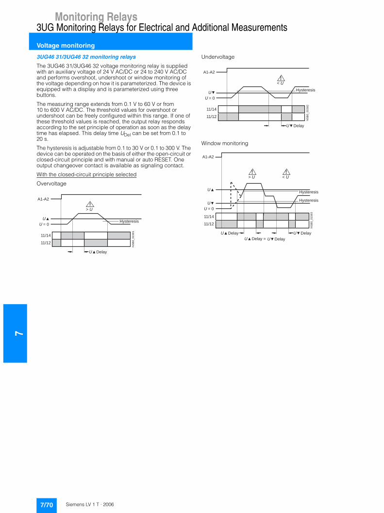
7Monitoring Relays
3UG Monitoring Relays for Electrical and Additional Measurements
Voltage monitoring
3UG46 31/3UG46 32 monitoring relays
The 3UG46 31/3UG46 32 voltage monitoring relay is supplied with an auxiliary voltage of 24 V AC/DC or 24 to 240 V AC/DC and performs overshoot, undershoot or window monitoring of the voltage depending on how it is parameterized. The device is equipped with a display and is parameterized using three buttons.
The measuring range extends from 0.1 V to 60 V or from 10 to 600 V AC/DC. The threshold values for overshoot or undershoot can be freely configured within this range. If one of these threshold values is reached, the output relay responds according to the set principle of operation as soon as the delay time has elapsed. This delay time UDel can be set from 0.1 to 20 s.
The hysteresis is adjustable from 0.1 to 30 V or 0.1 to 300 V. The device can be operated on the basis of either the open-circuit or closed-circuit principle and with manual or auto RESET. One output changeover contact is available as signaling contact.
With the closed-circuit principle selected
Overvoltage
Undervoltage
Window monitoring
NS
B0
_0
15
81
>
11/14
11/12
= 0
A1-A2
Hysteresis
Delay
NS
B0
_0
15
82
<
11/14
11/12
= 0
A1-A2
Hysteresis
Delay
NS
B0
_0
15
83
>
11/14
11/12
= 0
A1-A2
<
Hysteresis
Hysteresis
Delay Delay
Delay = Delay
7/70 Siemens LV 1 T · 2006
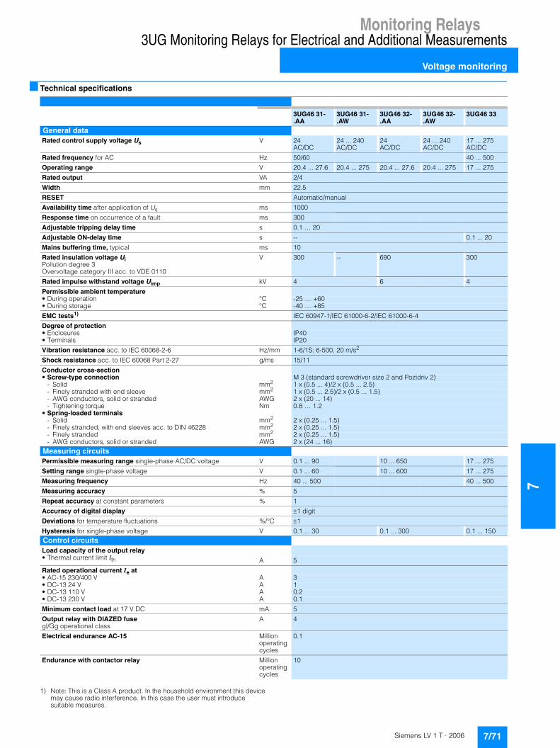
Monitoring Relays
7
3UG Monitoring Relays for Electrical and Additional Measurements
Voltage monitoring
■ Technical specifications
1) Note: This is a Class A product. In the household environment this device may cause radio interference. In this case the user must introduce suitable measures.
3UG46 31-.AA
3UG46 31-.AW
3UG46 32-.AA
3UG46 32-.AW
3UG46 33
General dataRated control supply voltage Us V 24
AC/DC24 ... 240AC/DC
24 AC/DC
24 ... 240AC/DC
17 ... 275AC/DC
Rated frequency for AC Hz 50/60 40 ... 500
Operating range V 20.4 ... 27.6 20.4 ... 275 20.4 ... 27.6 20.4 ... 275 17 ... 275
Rated output VA 2/4
Width mm 22.5
RESET Automatic/manual
Availability time after application of Us ms 1000
Response time on occurrence of a fault ms 300
Adjustable tripping delay time s 0.1 … 20
Adjustable ON-delay time s -- 0.1 ... 20
Mains buffering time, typical ms 10
Rated insulation voltage UiPollution degree 3Overvoltage category III acc. to VDE 0110
V 300 -- 690 300
Rated impulse withstand voltage Uimp kV 4 6 4
Permissible ambient temperature • During operation °C -25 … +60• During storage °C -40 … +85
EMC tests1) IEC 60947-1/IEC 61000-6-2/IEC 61000-6-4
Degree of protection• Enclosures IP40• Terminals IP20
Vibration resistance acc. to IEC 60068-2-6 Hz/mm 1-6/1S; 6-500, 20 m/s2
Shock resistance acc. to IEC 60068 Part 2-27 g/ms 15/11
Conductor cross-section• Screw-type connection M 3 (standard screwdriver size 2 and Pozidriv 2)
- Solid mm2 1 x (0.5 ... 4)/2 x (0.5 ... 2.5)- Finely stranded with end sleeve mm2 1 x (0.5 ... 2.5)/2 x (0.5 ... 1.5)- AWG conductors, solid or stranded AWG 2 x (20 ... 14)- Tightening torque Nm 0.8 … 1.2
• Spring-loaded terminals- Solid mm2 2 x (0.25 ... 1.5)- Finely stranded, with end sleeves acc. to DIN 46228 mm2 2 x (0.25 ... 1.5)- Finely stranded mm2 2 x (0.25 ... 1.5)- AWG conductors, solid or stranded AWG 2 x (24 ... 16)
Measuring circuitsPermissible measuring range single-phase AC/DC voltage V 0.1 ... 90 10 ... 650 17 ... 275
Setting range single-phase voltage V 0.1 ... 60 10 ... 600 17 ... 275
Measuring frequency Hz 40 ... 500 40 ... 500
Measuring accuracy % 5
Repeat accuracy at constant parameters % 1
Accuracy of digital display �1 digit
Deviations for temperature fluctuations %/°C �1
Hysteresis for single-phase voltage V 0.1 ... 30 0.1 ... 300 0.1 ... 150Control circuitsLoad capacity of the output relay• Thermal current limit Ith A 5
Rated operational current Ie at• AC-15 230/400 V A 3• DC-13 24 V A 1• DC-13 110 V A 0.2• DC-13 230 V A 0.1
Minimum contact load at 17 V DC mA 5
Output relay with DIAZED fusegl/Gg operational class
A 4
Electrical endurance AC-15 Million operating cycles
0.1
Endurance with contactor relay Million operating cycles
10
7/71Siemens LV 1 T · 2006
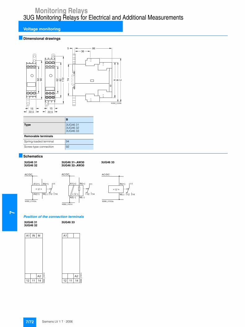
7Monitoring Relays
3UG Monitoring Relays for Electrical and Additional Measurements
Voltage monitoring
■ Dimensional drawings
■ Schematics
Position of the connection terminals
NSB0_01606
A B C74
86536
62 90
1522,5
62 110
1522,5
82
B
Type 3UG46 313UG46 323UG46 33
Removable terminals
Spring-loaded terminal 94
Screw-type connection 92
3UG46 313UG46 32
3UG46 31-.AW30 3UG46 32-.AW30
3UG46 33
� � � � � � � � � �
� �
� �
�
� � � � �
� � � � �
� � � � �
� � � � � � � � �
� � � � �
NSB0_01614
12
11
14
A1(+)
AC/DC
IN(+)
A2(–) M(–)
< U >
� � � � � � � � � �
� �
� �
�
� � � � �
� � � � �
� � � �
� � � � �
3UG46 313UG46 32
3UG46 33
����������
� �
� �
� � �
� � � � �
����������
� �
� �
� � � � �
7/72 Siemens LV 1 T · 2006
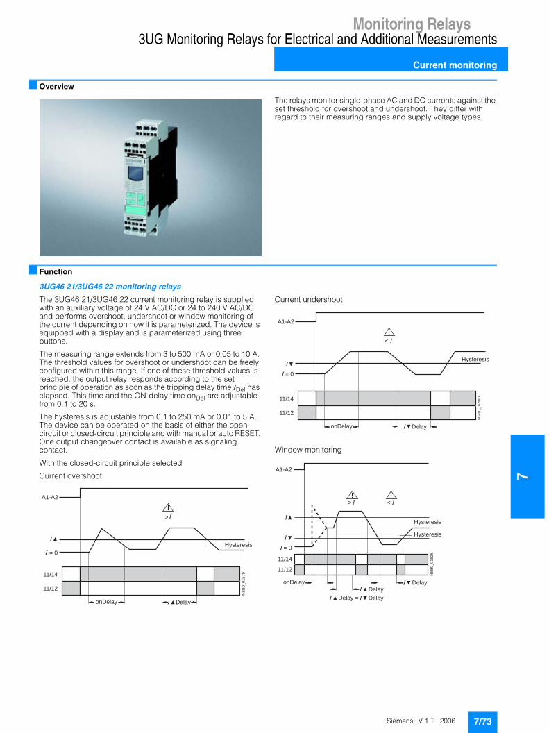
Monitoring Relays
7
3UG Monitoring Relays for Electrical and Additional Measurements
Current monitoring
■ Overview
The relays monitor single-phase AC and DC currents against the set threshold for overshoot and undershoot. They differ with regard to their measuring ranges and supply voltage types.
■ Function
3UG46 21/3UG46 22 monitoring relays
The 3UG46 21/3UG46 22 current monitoring relay is supplied with an auxiliary voltage of 24 V AC/DC or 24 to 240 V AC/DC and performs overshoot, undershoot or window monitoring of the current depending on how it is parameterized. The device is equipped with a display and is parameterized using three buttons.
The measuring range extends from 3 to 500 mA or 0.05 to 10 A. The threshold values for overshoot or undershoot can be freely configured within this range. If one of these threshold values is reached, the output relay responds according to the set principle of operation as soon as the tripping delay time IDel has elapsed. This time and the ON-delay time onDel are adjustable from 0.1 to 20 s.
The hysteresis is adjustable from 0.1 to 250 mA or 0.01 to 5 A. The device can be operated on the basis of either the open-circuit or closed-circuit principle and with manual or auto RESET. One output changeover contact is available as signaling contact.
With the closed-circuit principle selected
Current overshoot
Current undershoot
Window monitoring
NS
B0
_0
15
79
= 0
11/14
A1-A2
11/12
>
Hysteresis
DelayonDelay
NS
B0
_0
15
80
= 0
11/14
A1-A2
11/12
<
Hysteresis
DelayonDelayN
SB
0_
01
62
6
>
11/14
11/12
= 0
A1-A2
<
Hysteresis
Hysteresis
DelayDelay
DelayDelay =
onDelay
7/73Siemens LV 1 T · 2006
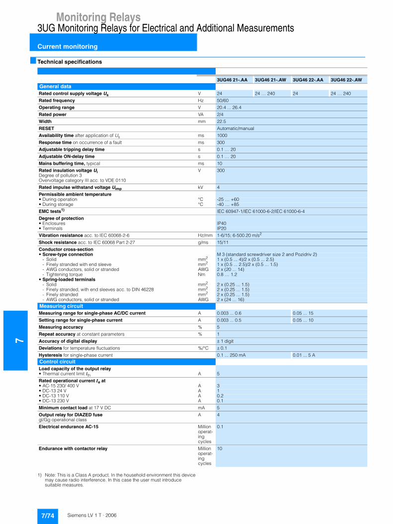
7Monitoring Relays
3UG Monitoring Relays for Electrical and Additional Measurements
Current monitoring
■ Technical specifications
1) Note: This is a Class A product. In the household environment this device may cause radio interference. In this case the user must introduce suitable measures.
3UG46 21-.AA 3UG46 21-.AW 3UG46 22-.AA 3UG46 22-.AWGeneral dataRated control supply voltage Us V 24 24 … 240 24 24 … 240
Rated frequency Hz 50/60
Operating range V 20.4 ... 26.4
Rated power VA 2/4
Width mm 22.5
RESET Automatic/manual
Availability time after application of Us ms 1000
Response time on occurrence of a fault ms 300
Adjustable tripping delay time s 0.1 … 20
Adjustable ON-delay time s 0.1 … 20
Mains buffering time, typical ms 10
Rated insulation voltage UiDegree of pollution 3Overvoltage category III acc. to VDE 0110
V 300
Rated impulse withstand voltage Uimp kV 4
Permissible ambient temperature• During operation °C -25 … +60• During storage °C -40 … +85
EMC tests1) IEC 60947-1/IEC 61000-6-2/IEC 61000-6-4
Degree of protection• Enclosures IP40• Terminals IP20
Vibration resistance acc. to IEC 60068-2-6 Hz/mm 1-6/15; 6-500.20 m/s2
Shock resistance acc. to IEC 60068 Part 2-27 g/ms 15/11
Conductor cross-section• Screw-type connection M 3 (standard screwdriver size 2 and Pozidriv 2)
- Solid mm2 1 x (0.5 ... 4)/2 x (0.5 ... 2.5)- Finely stranded with end sleeve mm2 1 x (0.5 ... 2.5)/2 x (0.5 ... 1.5)- AWG conductors, solid or stranded AWG 2 x (20 ... 14)- Tightening torque Nm 0.8 … 1.2
• Spring-loaded terminals- Solid mm2 2 x (0.25 ... 1.5)- Finely stranded, with end sleeves acc. to DIN 46228 mm2 2 x (0.25 ... 1.5)- Finely stranded mm2 2 x (0.25 ... 1.5)- AWG conductors, solid or stranded AWG 2 x (24 ... 16)
Measuring circuitMeasuring range for single-phase AC/DC current A 0.003 ... 0.6 0.05 ... 15
Setting range for single-phase current A 0.003 ... 0.5 0.05 ... 10
Measuring accuracy % 5
Repeat accuracy at constant parameters % 1
Accuracy of digital display ��1 digit
Deviations for temperature fluctuations %/°C ��0.1
Hysteresis for single-phase current 0.1 ... 250 mA 0.01 ... 5 AControl circuitLoad capacity of the output relay• Thermal current limit Ith A 5
Rated operational current Ie at• AC-15 230/ 400 V A 3• DC-13 24 V A 1• DC-13 110 V A 0.2• DC-13 230 V A 0.1
Minimum contact load at 17 V DC mA 5
Output relay for DIAZED fusegl/Gg operational class
A 4
Electrical endurance AC-15 Million operat-ing cycles
0.1
Endurance with contactor relay Million operat-ing cycles
10
7/74 Siemens LV 1 T · 2006

Monitoring Relays
7
3UG Monitoring Relays for Electrical and Additional Measurements
Current monitoring
■ Dimensional drawings
■ Schematics
Position of the connection terminals
NSB0_01606
A B C74
86536
62 90
1522,5
62 110
1522,5
82
B
Type 3UG46 213UG46 22
Removable terminals
Spring-loaded terminal 94
Screw-type terminal 92
3UG46 21-.AA30 3UG46 22-.AA30
3UG46 21-.AW30 3UG46 22-.AW30
NSB0_01534a
12
11
14
A1(+)
AC/DC
IN(+)
A2(–) M(–)
U
< >
Load
Load
NSB0_01535a
12
11
14
A1(+)
AC/DC
IN(+)
A2(–) M(–)
U
< >
Load
Load
3UG46 213UG46 22
����������
� �
� �
� � �
� � � � �
7/75Siemens LV 1 T · 2006

7Monitoring Relays
3UG Monitoring Relays for Electrical and Additional Measurements
Power factor monitoring
■ Overview
The 3UG30 14 power factor monitoring device enables the load monitoring of motors.
■ Function
The 3UG30 14 monitoring relay is used for monitoring the load of motors by measuring the phase angle between voltage and current, i.e. the power factor. The output relays respond as long as the power factor lies between the upper and lower thresholds. These are set separately on the front using two potentiometers.
When the value of the power factor lies outside this range, the corresponding output relay will drop after a delay time T1, that can be set on the front, has elapsed. A fixed hysteresis prevents the output relay from continuously switching on and off when the measured value is close to the threshold.
The ON-delay T2 can be used to suppress the effects of motor start-up.
Important
It is important to ensure that the phases are connected in the correct sequence L1-L2-L3, otherwise the power factor will be evaluated incorrectly.
Note:
Power factor monitoring relays are connected in series after the motor contactor to ensure that the delay time for bridging start-up elapses after switch-on. For this reason, the output relay must not be connected in series with the supply voltage of the motor contactor, otherwise it would not be possible to switch on the load feeder. The minimum current must be at least 0.2 A.
■ Technical specifications
1) Short-circuits without any contact welding acc. to DIN VDE 0660, Part 200.
� � � �
�
�
�
�
�
�
�
� � � � � � � � � �
�
�
�
�
! "
! # $
! "
! # $
% & ' � % � ( ) * + ( , '- . � / ' & ' � # � % & ' � % � ( ) * + ( , '0 , / 1 , / * & ' ( . * � � � * * * * 2 * � � �� / ' & ! # $ ( � * � � 3 * � � 3 * � �0 , / 1 , / * & ' ( . * � � � * * * * 4 * � � �� / ' & ! # $ ( � * � � 3 * � � 3 * � �
Type 3UG30/3UG35
Load capacity of the output relay Rated operational current Ie A max. 8AC-15/230 V A 3DC-13/24 V A 1DC-13/48 V A 0.45DC-13/60 V A 0.35DC-13/110 V A 0.2DC-13/230 V A 0.1
Minimum contact load mA 5/17 V for a fault of 1 ppm
Output relay with DIAZED fuse1) gl/Gg operational class A 4
Electrical endurance Operating cycles 1 x 10⁵
Mechanical endurance Operating cycles 2 x 10⁶
Ambient temperature During operation °C -20 ... + 50During storage °C -30 ... + 70
Connection of conductors Solid mm² 2 x (0.5 ... 2.5)Finely stranded, with end sleeves mm² 2 x (0.5 ... 1.5)
Degree of protection Terminals IP20Enclosures IP40
Vibration resistance acc. to IEC 60068-2-6 Hz/mm 10 ... 150/0.035
7/76 Siemens LV 1 T · 2006
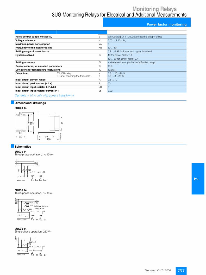
Monitoring Relays
7
3UG Monitoring Relays for Electrical and Additional Measurements
Power factor monitoring
Currents > 10 A only with current transformer.
■ Dimensional drawings
3UG30 14
■ Schematics
3UG30 14Three-phase operation, I < 10 A~
3UG30 14Three-phase operation, I > 10 A~
3UG30 14Single-phase operation, 230 V~
Rated control supply voltage Us V see Catalog LV 1 (L1/L2 also used to supply units)
Voltage tolerance V 0.85 ... 1.15 x Us
Maximum power consumption VA 3
Frequency of the monitored line Hz 50 ... 60
Setting range of power factor 0.1 ... 0.99 for lower and upper threshold
Hysteresis fixed % 10 for power factor 0.4
10 ... 30 for power factor 0.4
Setting accuracy % �10 referred to upper limit of effective range
Repeat accuracy at constant parameters % �0.8
Deviations for temperature fluctuations % �0.05/K
Delay time T2, ON-delay s 0.5 ... 20; �20 %T1 after reaching the threshold s 0.3 ... 3; �20 %
Input circuit current range A 0.5 ... 10
Input circuit peak current (< 1 s) A 50
Input circuit input resistor L1/L2/L3 k� 2
Input circuit input resistor current IN1 � 0.02
��
��
��
��
��
��
��
��
�
��
�
NSB01130b
L1
12
11
14
L2 L3
L2L3
L1
22
21
24
M
IN1< p. f. > p. f.
> p. f. <
NSB0_01131c
L1
12
11
14
L2 IN1
L2L3
L1
22
21
24
M
L3
K(P ) L(P )
k(S ) l(S )
1 2
1 2
> p. f. <
< p. f. > p. f.
external currenttransformer
NSB01132b
L1
12
11
14
L2 L3
LN
22
21
24
< p. f. > p. f.
> p. f. <
IN1
Load
7/77Siemens LV 1 T · 2006
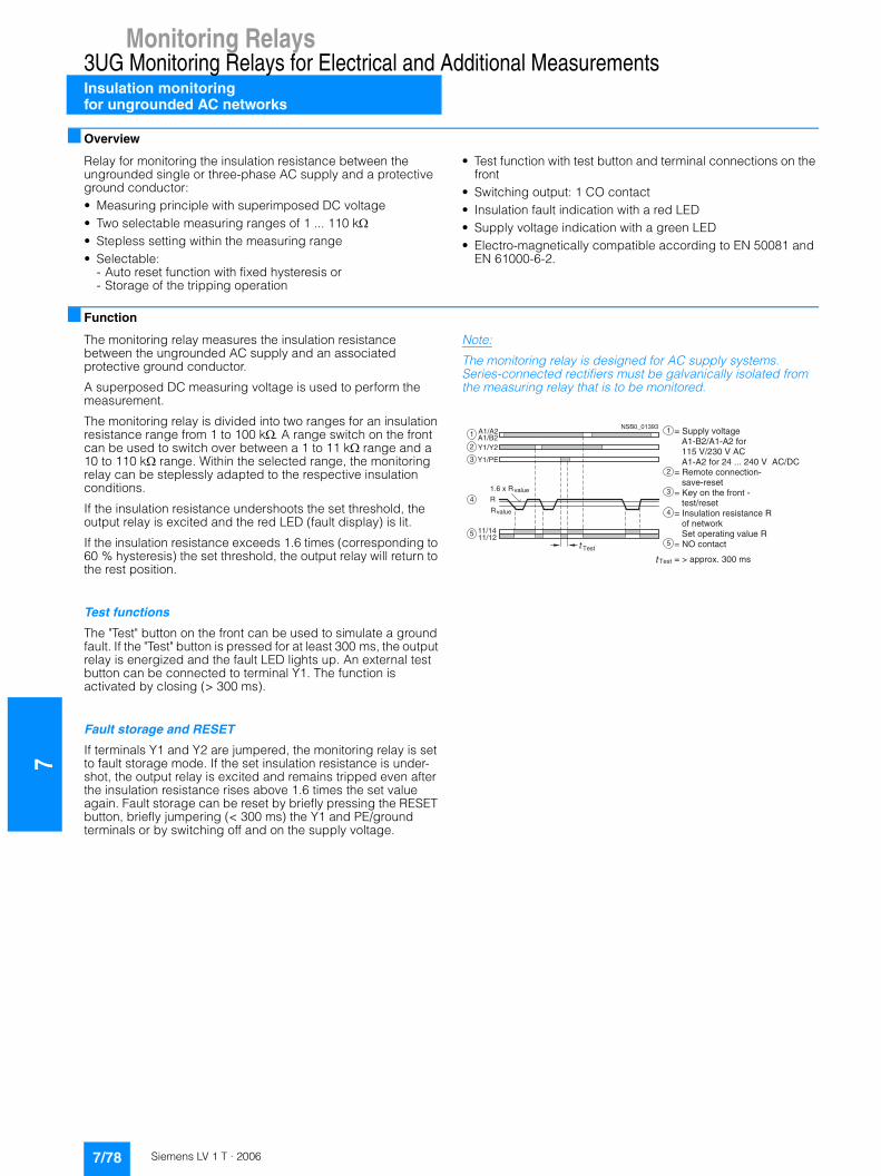
7Monitoring Relays
3UG Monitoring Relays for Electrical and Additional MeasurementsInsulation monitoringfor ungrounded AC networks
■ Overview
Relay for monitoring the insulation resistance between the ungrounded single or three-phase AC supply and a protective ground conductor:• Measuring principle with superimposed DC voltage• Two selectable measuring ranges of 1 ... 110 k�• Stepless setting within the measuring range• Selectable:
- Auto reset function with fixed hysteresis or- Storage of the tripping operation
• Test function with test button and terminal connections on the front
• Switching output: 1 CO contact• Insulation fault indication with a red LED• Supply voltage indication with a green LED• Electro-magnetically compatible according to EN 50081 and
EN 61000-6-2.
■ Function
The monitoring relay measures the insulation resistance between the ungrounded AC supply and an associated protective ground conductor.
A superposed DC measuring voltage is used to perform the measurement.
The monitoring relay is divided into two ranges for an insulation resistance range from 1 to 100 k�. A range switch on the front can be used to switch over between a 1 to 11 k� range and a 10 to 110 k� range. Within the selected range, the monitoring relay can be steplessly adapted to the respective insulation conditions.
If the insulation resistance undershoots the set threshold, the output relay is excited and the red LED (fault display) is lit.
If the insulation resistance exceeds 1.6 times (corresponding to 60 % hysteresis) the set threshold, the output relay will return to the rest position.
Test functions
The "Test" button on the front can be used to simulate a ground fault. If the "Test" button is pressed for at least 300 ms, the output relay is energized and the fault LED lights up. An external test button can be connected to terminal Y1. The function is activated by closing (> 300 ms).
Fault storage and RESET
If terminals Y1 and Y2 are jumpered, the monitoring relay is set to fault storage mode. If the set insulation resistance is under-shot, the output relay is excited and remains tripped even after the insulation resistance rises above 1.6 times the set value again. Fault storage can be reset by briefly pressing the RESET button, briefly jumpering (< 300 ms) the Y1 and PE/ground terminals or by switching off and on the supply voltage.
Note:
The monitoring relay is designed for AC supply systems. Series-connected rectifiers must be galvanically isolated from the measuring relay that is to be monitored.
A1/A2A1/B2Y1/Y2
Y1/PE
11/1411/12
1
2
3
R4
5
value
Rvalue
Test
NSB0_01393
Test
1
2
3
4
5
= > approx. 300 ms
= Supply voltage A1-B2/A1-A2 for 115 V/230 V AC A1-A2 for 24 ... 240 V AC/DC = Remote connection- save-reset= Key on the front - test/reset= Insulation resistance R of network Set operating value R= NO contact
1.6 x R
7/78 Siemens LV 1 T · 2006
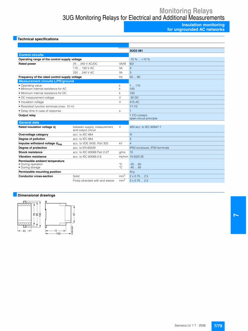
Monitoring Relays
7
3UG Monitoring Relays for Electrical and Additional MeasurementsInsulation monitoring
for ungrounded AC networks
■ Technical specifications
■ Dimensional drawings
3UG3 081Control circuitsOperating range of the control supply voltage -15 % ... +10 %
Rated power 24 ... 240 V AC/DC VA/W 8/2
110 ... 130 V AC VA 3
220 ... 240 V AC VA 3
Frequency of the rated control supply voltage Hz 50 ... 60Measurement circuits L/PE/ground• Operating value k 1 ... 110• Minimum internal resistance for AC k 100
• Minimum internal resistance for DC k 100
• DC measurement voltage V 30 DC
• Insulation voltage V 415 AC
• Reset/test function terminals (max. 10 m) Y1-Y2
• Delay time in case of response s 1
Output relay 1 CO contact,open-circuit principle
General data Rated insulation voltage Ui between supply, measurement,
and output circuitV 400 acc. to IEC 60947-1
Overvoltage category acc. to IEC 664 III
Degree of pollution acc. to IEC 664 3
Impulse withstand voltage Uimp acc. to VDE 0435, Part 303 kV 4
Degree of protection acc. to EN 60529 IP50 enclosure, IP20 terminals
Shock resistance acc. to IEC 60068 Part 2-27 g/ms 10
Vibration resistance acc. to IEC 60068-2-6 Hz/mm 10-55/0.35
Permissible ambient temperature• During operation °C -25 ... 65• During storage °C -40 ... 85
Permissible mounting position Any
Conductor cross-section Solid mm2 2 x 0.75 ... 2.5
Finely stranded with end sleeve mm2 2 x 0.75 ... 2.5
��
��
��
��
��
��
��
��
�
��
�
7/79Siemens LV 1 T · 2006

7Monitoring Relays
3UG Monitoring Relays for Electrical and Additional MeasurementsInsulation monitoringfor ungrounded DC networks
■ Overview
Relay for monitoring the insulation resistance between ungrounded pure DC networks and a protective-ground conductor:• Measuring principle for differential current measurement• Response threshold can be set continuously from
10 to 110 k�• Selectable
- Auto reset function with hysteresis or- Storage of the tripping operation
• Front selector switch for open-circuit and closed-circuit principle for the output relay
• Test function with test buttons on the front for L+ and L-and over terminal connections
• Switching output: 1 CO contact• Insulation fault indicator for L+ and L- through two red LEDs• Supply voltage indication with a green LED• Electro-magnetically compatible according to EN 50081 and
EN 61000-6-2
■ Function
The monitoring relay measures the insulation voltage between the positive and negative supply voltage in an ungrounded DC network and a corresponding protective conductor.
The measurement is based on the DC residual current measurement principle. The response value can be adjusted steplessly in the range from 10 to 110 k� and thus can be adapted to the corresponding conditions. If the insulation resistance falls below the set response value, the output relay triggers (depending on the setting of the open/closed-circuit principle selector switch) and a fault LED lights up.
A ground fault is evaluated separately for L+ and L- and indicated by means of a corresponding LED.
Note:
Due to the measurement principle, a symmetrical ground fault on terminals L+ and L- cannot be evaluated.
Test function
A ground fault can be simulated using the Test L+ and Test L- buttons on the front. If the test button is pressed for at least 1 s, the status of the output relay changes and the corresponding fault LED lights up.
An external test button can be connected to terminals Y1-Y3 for L+ and terminals Y4-Y3 for L-. The function is triggered by means of a NO contact.
Fault storage and RESET
If terminals Y2 and Y3 are linked, the monitoring relay is set to fault storage mode.
If the insulation resistance falls below the set value, the output relay triggers (depending on the setting of the open/closed circuit selector switch), and stays in this state even if the insulation resistance rises again above the hysteresis value (typical: 2 times the set value). This fault storage can be deleted by pressing and releasing the L+ RESET button, opening the Y2-Y3 connection or by switching off the supply voltage.
Open/closed-circuit principle selector switch
The function principle of the output relay can be adjusted by means of a selector switch on the front panel.
If the relay is to respond in the event of a fault (contact symbol open), the open-circuit principle must be selected. If the relay however is to trigger in the event of a fault (contact symbol closed), the closed-circuit principle must be selected.
Note:
The position of the selector switch has no effect upon the fault LEDs. The LEDs always light up if the insulation resistance on L+ or L– falls below the set value.
� � � � �
� � � � �
� � � � �� � � � �
�
� � � � � � �
� � � � � �
� � � � �
� � � � �
� � � � �� � � � �
�
�
�
�
�
�
�
�
� � � � �
�
�
�
�
�
�
�
�
�� � � �
! " � � #
� ! " � �
$ % � & �' ( ) ' � ( � * �
' � + � � , �' ( ) ' � ( �% ) ( & ' ( % � �
- * � % % ) + # . * � * �
* - * � " % ( ' � � � " * � * # * �
- * � % % � " * � + � � � / �- * � � � � + & * + & * 0 ) + & � * �* * * � � � � � * � � * � & , * � � * �* * * � � � � * � �
- * � � � � + & * + & * 0 ) + & � * � * * � � � � * � �* * * � � � � * ) � 1 + � � * ' + & & � ' � ( + & * �
* * * � � � � * � �- * � � � � * ) � 1 + � � * ' + & & � ' � ( + & * �* * * � � � � * � �- * � � � � * ) � 1 + � � * ' + & & � ' � ( + & * �
* * * � + ) � 2 * ) � � � �- * 3 & � � � � � ( + & * ) � � ( � � � & ' � * �* * * + 0 * � � % % � "
* * * � � � * ) � � % + & � � * � � � � � * �- * 4 ( � ' 5 * + & * 0 ) + & �
* * * $ % � & � ' ( ) ' � ( � * �* * * ' � + � � , � ' ( ) ' � ( � * % ) ( & ' ( % � �- * $ * ' + & � � ' �
7/80 Siemens LV 1 T · 2006
Monitoring Relays
7
3UG Monitoring Relays for Electrical and Additional MeasurementsInsulation monitoring
for ungrounded DC networks
■ Technical specifications
■ Dimensional drawings
3UG30 82Control circuitsOperating range of the control supply voltage -15 % ... +10 %
Rated power 24 ... 240 V AC VA/W 8/2
Frequency of the rated control supply voltage Hz 50 ... 60Measuring circuits• Operating value k 10 ... 110
• Minimum internal resistance for DC k 57
• Measurement DC voltage V 24 ... 240
• Max. DC insulation voltage (L+/PE/ground, L-/PE/ground) V DC 300
• Reset/test function terminals (max. 10 m) Y1/Y3, Y4/Y3
• Delay time in case of response s 1
Output relay 1 changeover contact, open-circuit or closed-circuit principleGeneral data Rated insulation voltage Ui Insulation resistance
between supply, measurement, and output circuit
V 400
Overvoltage category acc. to IEC 664 IIIDegree of pollution acc. to IEC 664 3
Impulse withstand voltage Uimp acc. to VDE 0435, Part 303 V 4000
Degree of protection acc. to EN 60529 IP50 enclosure, IP20 terminals
Shock resistance acc. to IEC 60068 Part 2-27 g/ms 10
Vibration resistance acc. to IEC 60068-2-6 Hz/mm 10-55/0.35
Permissible ambient temperature• During operation °C -25 ... + 65• During storage °C -40 ... + 85
Permissible mounting position any
Conductor cross-section Solid mm2 2 x 0.75 ... 2.5
Finely stranded with end sleeve mm2 2 x 0.75 ... 2.5
��
��
��
��
��
��
��
��
�
��
�
7/81Siemens LV 1 T · 2006
7Monitoring Relays
3UG Monitoring Relays for Electrical and Additional Measurements
Level monitoring
■ Overview
The 3UG35 01 level monitoring relay is used together with the 2- or 3-pole sensors to monitor the levels of conductive liquids.
■ Function
The principle of operation is based on measuring the electrical resistance of the liquid between two immersion sensors and a reference terminal. If the measured value is lower than the sensitivity set at the front, the output relay changes its switching state. In order to exclude electrolytic phenomena in the liquid, the sensors are supplied with alternating current.
Two-level control: the output relay changes its switching state as soon as the liquid level reaches the maximum sensor, while the minimum sensor is submerged. The relay returns to its original switching state as soon as the minimum sensor no longer has contact with the liquid.
For safe resetting, the supply voltage must be interrupted for at least 0.5 s (T3).
The delay times T1 and T2 of the output relay have not been included in the diagram in order to enhance clarity.
Note:
It is also possible to connect other resistance sensors to the Min and Max terminals in the range 5 to 100 k�, e.g. photoresistors, temperature sensors, encoders based on resistance etc. The monitoring relay can therefore also be used for other applications apart from monitoring the levels of liquids.
� � � � � � � � � � � �
�
�
�
�
�
�
�
�
�
�
�
�
� � � � � � � � � � � � � � � � � � � � � � � � � � � � � � � �� � � � � � � � ! � � � � " � � � � � � � � � � � � � � � � � � # � $ % � � &
' � ( � � % � � # � ) � # � � �' � � � � % � � # � ) � # � � �' � � � � � � � � � # � ) � #* % � ! % � � � � # � �+ % � , � � � � � * - . /* % � ! % � � � � # � �+ % � , � � � � � 0 � � . /
7/82 Siemens LV 1 T · 2006

Monitoring Relays
7
3UG Monitoring Relays for Electrical and Additional Measurements
Level monitoring
■ Technical specifications
1) Short-circuits without any contact welding acc. toDIN VDE 0660 Part 200.
1) The sensor cable does not necessarily have to be shielded, but it is not recommended to lay this cable parallel to the power supply lines. It is also possible to use a shielded cable, whereby the shield has to be connected to the M terminal.
Type 3UG30/3UG35
Load capacity of the output relay Rated operational current Ie A max. 8AC-15/230 V A 3DC-13/24 V A 1DC-13/48 V A 0.45DC-13/60 V A 0.35DC-13/110 V A 0.2DC-13/230 V A 0.1
Minimum contact load mA 5/17 V for a fault of 1 ppm
Output relay with DIAZED fuse1) gl/Gg operational class A 4
Electrical endurance Operating cycles 1 x 10⁵
Mechanical endurance Operating cycles 2 x 10⁶
Ambient temperature During operation °C -20 ... + 50During storage °C -30 ... + 70
Connection of conductors Solid mm² 2 x (0.5 ... 2.5)Finely stranded, with end sleeves mm² 2 x (0.5 ... 1.5)
Degree of protection Terminals IP20Enclosures IP40
Vibration resistance acc. to IEC 60068-2-6 Hz/mm 10 ... 150/0.035
Rated control supply voltage Us V see Catalog LV 1 (electrical isolation by means of a transformer)
Voltage tolerance 0.85 ... 1.1 x Us
Maximum power consumption W/VA 3/6
Function Inlet or outlet monitoring UNDER/OVER selector switch at the front
Sensitivity Adjustable k� 5 ... 100
Setting accuracy at maximum sensitivity % �30
Repeat accuracy at constant parameters % �0.1
Sensor length max. m 100
Electrode voltage max. V 24 (50/60 Hz)
Electrode current max. mA 1 (50/60 Hz)
Conductor capacity of the sensor cable1) nF 10
Delay time• T1 at Max/M terminal ms Typical 500 (ON-delay with OVER, OFF-delay with UNDER)• T2 at Min/M terminal ms Typical 300 (OFF-delay with OVER, ON-delay with UNDER)
Mains buffering time ms 300
7/83Siemens LV 1 T · 2006

7Monitoring Relays
3UG Monitoring Relays for Electrical and Additional Measurements
Level monitoring
■ Dimensional drawings
3UG35 01
Level monitoring sensors
3UG32 07-3Athree-pole wire electrode
3UG32 07-2Atwo-pole wire electrode
3UG32 07-2Btwo-pole bow electrode
3UG32 07-1Bsingle-pole bow electrode
3UG32 07-1Csingle-pole electrode, rugged design
■ Schematics
3UG35 01
������
������
�
���
���
��
�
��
��
� ���
���
�
�������
��
��
� ���
���
�
������
����������
���
� ���
� �������
����������
���
� ���
������
��
��
� ���
��
��
������
���������������
��
��!"
��
��
��
�#
���� �$
�������
7/84 Siemens LV 1 T · 2006
Monitoring Relays
7
3UG Monitoring Relays for Electrical and Additional Measurements
Speed monitoring
■ Overview
The 3UG30 51 monitoring relay is used together with a sensor to monitor drives for underspeeding.
■ Function
The underspeed monitoring relay operates according to the principle of retriggerable OFF-delay. During the time (value) set on the front panel, another pulse must arrive at input IN1 or IN2 to ensure that the output relay remains picked up. The monitoring relay evaluates the rising edge of the signal, i.e. a continuous signal is also recognized as a missing pulse. If the retrigger pulse does not arrive, indicating a reduction in speed, the output relay drops. In order to be able to start a drive, the output relay remains picked up during the ON-delay time T, even if the speed is still below the set value (motor starting override time). The first pulse must come within this time.
The monitoring relay can be used for all functions where a continuous pulse signal needs to be monitored (belt travel monitoring, completeness monitoring, passing monitoring, clock-time monitoring).
Speed monitoring without memory (NO MEMORY)
When the speed of the drive drops below the set value, the output relay drops. It picks up again when the speed is greater than the set value plus the fixed hysteresis.
Speed monitoring with memory (MEMORY)
When the output relay drops, this state remains stored even when the speed reaches a permissible value again. The stored state can be ended by a control signal at the reset terminal or by interrupting the supply voltage for at least 200 ms.
■ Technical specifications
1) Short-circuits without any contact welding acc. toDIN VDE 0660 Part 200.
� � � � � � � � � � � �
�
�
�
�
�
�
� � � � � � � � �� � � � � � � � � � � � � � � � � � � � �� � � � � � � � � � � �
� � � � � � � � � � � �
�
�
�
�
� �
�
�
�
�
�
� � � � � � � � �� � � � � � � � � � � � � � � � � � � � �� � � � � � � � � � � �� � � � �� � � � ! � � " # $ # � � % &
Type 3UG30/3UG35
Load capacity of the output relay Rated operational current Ie A max. 8AC-15/230 V A 3DC-13/24 V A 1DC-13/48 V A 0.45DC-13/60 V A 0.35DC-13/110 V A 0.2DC-13/230 V A 0.1
Minimum contact load mA 5/17 V for a fault of 1 ppm
Output relay with DIAZED fuse1) gl/Gg operational class A 4
Electrical endurance Operating cycles 1 x 10⁵
Mechanical endurance Operating cycles 2 x 10⁶
Ambient temperature During operation °C -20 ... + 50During storage °C -30 ... + 70
Connection of conductors Solid mm² 2 x (0.5 ... 2.5) Finely stranded, with end sleeves mm² 2 x (0.5 ... 1.5)
Degree of protection Terminals IP20Enclosures IP40
Vibration resistance acc. to IEC 60068-2-6 Hz/mm 10 ... 150/0.035
7/85Siemens LV 1 T · 2006
7Monitoring Relays
3UG Monitoring Relays for Electrical and Additional Measurements
Speed monitoring
1) The sensors are not included in the scope of supply.
■ Dimensional drawings
■ Schematics
Type 3UG30 51
Rated control supply voltage Us V See Catalog LV 1 (for AC voltages with electrical isolation by means of transformer, 24 V DC without electrical isolation)
Voltage tolerance 0.85 ... 1.15 x Us
Maximum power consumption W/VA 4/5
Set value % Adjustable to 10 ... 100 of the selected time setting range
Hysteresis % Typical 5 of the set value
Setting accuracy % 10 referred to upper limit of time setting range
Repeat accuracy at constant parameters % �0.5
Deviations with temperature fluctuations %/°C 0.1
ON-delay T s Adjustable to 0.3 ... 30 �10 %
Signal input IN11) (Input resistance 16 k) V Max. voltage 30, 3-wire sensor, pnp operation
Signal input IN21) (Input resistance 1 k) Floating contact, 2-wire NAMUR sensor
Voltage level for reliable operation Level 1 V 4.5 ... 30Level 0 V 0 up to 1
Sensor supply +24 V/0 V mA max. 50 at 24 V (20 ... 35 V) DC+8 V2 mA 1 DC 8.2 V
Measuring range,selectable (rotary switch on front) Time setting range
• 0.1 ... 1 s- Frequency Hz 10 ... 1- Revolutions min-1 600 ... 60
• 1 ... 10 s- Frequency Hz 1 ... 0.1- Revolutions min-1 60 ... 6
• 0.1 ... 1 min- Frequency Hz 0.17 ... 0.017- Revolutions min-1 10 ... 1
• 1 ... 10 min- Frequency Hz 0.017 ... 0.0017- Revolutions min-1 1 ... 0.1- Minimum pulse duration of signal ms 5- Minimum interval between 2 pulses 5
Function mode setting with or without memory Rotary switch on front panel
Availability time after application of Us ms 200
Mains buffering time ms 10
��
��������
��
��
��
�
��
�
��
�� �
�
�
�
���������
� � �����
��� �� ���
� � �
���
��� � ���
� �����
�
�
� !"
7/86 Siemens LV 1 T · 2006
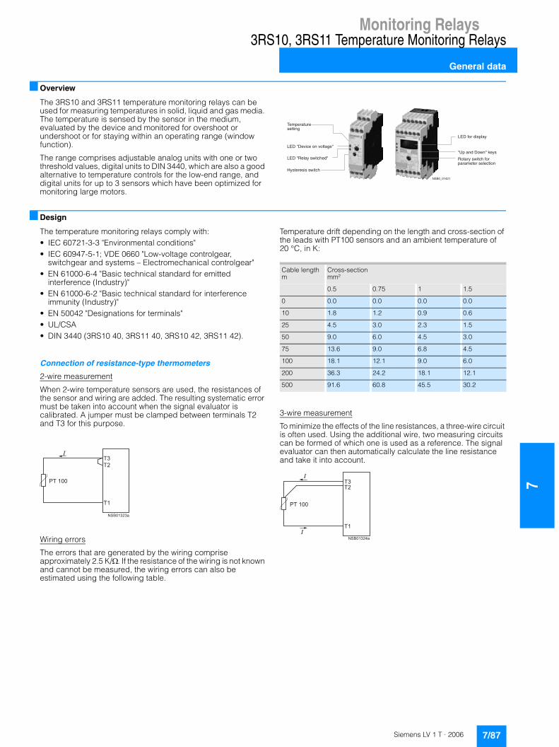
Monitoring Relays
7
3RS10, 3RS11 Temperature Monitoring Relays
General data
■ Overview
The 3RS10 and 3RS11 temperature monitoring relays can be used for measuring temperatures in solid, liquid and gas media. The temperature is sensed by the sensor in the medium, evaluated by the device and monitored for overshoot or undershoot or for staying within an operating range (window function).
The range comprises adjustable analog units with one or two threshold values, digital units to DIN 3440, which are also a good alternative to temperature controls for the low-end range, and digital units for up to 3 sensors which have been optimized for monitoring large motors.
■ Design
The temperature monitoring relays comply with:• IEC 60721-3-3 "Environmental conditions"• IEC 60947-5-1; VDE 0660 "Low-voltage controlgear,
switchgear and systems – Electromechanical controlgear"• EN 61000-6-4 "Basic technical standard for emitted
interference (Industry)"• EN 61000-6-2 "Basic technical standard for interference
immunity (Industry)"• EN 50042 "Designations for terminals"• UL/CSA• DIN 3440 (3RS10 40, 3RS11 40, 3RS10 42, 3RS11 42).
Connection of resistance-type thermometers
2-wire measurement
When 2-wire temperature sensors are used, the resistances of the sensor and wiring are added. The resulting systematic error must be taken into account when the signal evaluator is calibrated. A jumper must be clamped between terminals T2 and T3 for this purpose.
Wiring errors
The errors that are generated by the wiring comprise approximately 2.5 K/�. If the resistance of the wiring is not known and cannot be measured, the wiring errors can also be estimated using the following table.
Temperature drift depending on the length and cross-section of the leads with PT100 sensors and an ambient temperature of 20 °C, in K:
3-wire measurement
To minimize the effects of the line resistances, a three-wire circuit is often used. Using the additional wire, two measuring circuits can be formed of which one is used as a reference. The signal evaluator can then automatically calculate the line resistance and take it into account.
�7=972,18276711-.>
��%�?%7:-/7�0.�:031,>7?
��%�?!73,@�65-1/A7<?
�@617276-6�65-1/A
��%�;02�<-693,@
?�9�,.<�%05.?�47@6
!01,2@�65-1/A�;029,2,=7172�6737/1-0.
����+�����
����#�#�
�$ ��
$
$�$#
�
Cable length m
Cross-sectionmm²
0.5 0.75 1 1.5
0 0.0 0.0 0.0 0.0
10 1.8 1.2 0.9 0.6
25 4.5 3.0 2.3 1.5
50 9.0 6.0 4.5 3.0
75 13.6 9.0 6.8 4.5
100 18.1 12.1 9.0 6.0
200 36.3 24.2 18.1 12.1
500 91.6 60.8 45.5 30.2
����#���
�$ ��
$
$�$#
�
�
7/87Siemens LV 1 T · 2006

7Monitoring Relays
3RS10, 3RS11 Temperature Monitoring Relays
General data
Connection of thermocouples
Based on the thermo-electrical effect, a differential temperature measurement will be performed between the measuring point and the signal evaluator.
This principle assumes that the signal evaluator knows the temperature at the clamping point (T2). For this reason, the 3RS11 temperature monitoring relay has an integral compen-sator that determines this comparison temperature and builds it into the result of the measurement. Therefore, the thermal sensors and cables must be insulated.
The absolute temperature is calculated from the ambient temperature of the signal evaluator and the temperature difference measured by the thermocouple.
Temperature detection is therefore possible (T1) without needing to know the precise ambient temperature of the clamping point at the signal evaluator (T2).
The connecting cable is only permitted to be extended using connecting leads that are made from the same material as the thermocouple. If a different type of conductor is used, an error will result in the measurement.
You can find more information on the Internet at:
http://www.feldgeraete.de/76/produkte/fuw.html http://www.ephy-mess.de
or from
EPHY-MESS GmbH (see Appendix, External Partners)
■ Function
Once the temperature has reached the set threshold �1, the output relay K1 changes its output state as soon as the set time t has elapsed (K2 responds in the same manner to �2). The time delay can only be adjusted with digital units (on analog units, t = 0).
The relays return to their original state as soon as the temperature reaches the set hysteresis value.
Temperature overshoot
Closed-circuit principle
Temperature undershoot
Closed-circuit principle
� � � � � � � � �
� � � �
� �
� � �
� � � � � � � � � � � � � � � � � � � � �� � � � � � � � � � � � � � � � � � � � � � � � � � �
��������
�
��
�
��
��
�
�
�
�
������� �
�
� �
�
��
��
�
�
�
�
7/88 Siemens LV 1 T · 2006
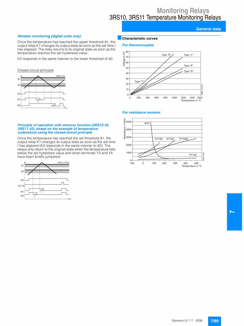
Monitoring Relays
7
3RS10, 3RS11 Temperature Monitoring Relays
General data
Window monitoring (digital units only)
Once the temperature has reached the upper threshold �1, the output relay K1 changes its output state as soon as the set time t has elapsed. The relay returns to its original state as soon as the temperature reaches the set hysteresis value.
K2 responds in the same manner to the lower threshold of �2.
Closed-circuit principle
Principle of operation with memory function (3RS10 42, 3RS11 42), based on the example of temperature undershoot using the closed-circuit principle
Once the temperature has reached the set threshold �1, the output relay K1 changes its output state as soon as the set time t has elapsed (K2 responds in the same manner to �2). The relays only return to the original state when the temperature falls below the set hysteresis value and when terminals Y3 and Y4 have been briefly jumpered.
■ Characteristic curves
For thermocouples
For resistance sensors
��
���������
�
��
��
�
�
�
�
�
� � � � � � � � � �
�
�
� � � �
� �
�� �
�
�
�
�
����������������������������������������������������������������������������
��
(�
�
��
��
��
��
��
� ����+
����
�,
�7=972,1827�-.�B�
�031,
>7�-.
�=�
�@97�?�? �@97�?C?
�@97�?&?
�@97�?�?
�@97�?�?
���������������������������������������������������������������������������������
����
����
����
����
����
�
���
&�'�� &�'�� ������
�����
����+
����
�
�7=972,1827�-.�B�
!76
-61,./
7�-.�"
A=
7/89Siemens LV 1 T · 2006

7Monitoring Relays
3RS10, 3RS11 Temperature Monitoring Relays
Relays, analog adjustable
■ Overview
The 3RS10/3RS11 analog temperature monitoring relays can be used for measuring temperatures in solid, liquid and gas media. The temperature is sensed by the sensors in the medium,
evaluated by the device and monitored for overshoot or undershoot. When the threshold values are reached, the output relay switches on or off depending on the setting.
■ Technical specifications
1) 2-wire connection of resistance sensors with wire jumper between T2 and T3.
Type 3RS10 00 3RS10 10 3RS11 00 3RS11 01 3RS10 20 3RS10 30 3RS11 20 3RS11 21General dataSensor type PT100 TC type J TC type K PT100 TC type J TC type K
Width mm 22.5
Operating range 0.85 ... 1.1 x Us
Rated power W/VA < 2/4Auxiliary circuitsContacts 1 NO + 1 NC 1 CO + 1 NO
Rated operational currents Ie • AC-15 at 230 V, 50 Hz A 3• DC-13 at:
- 24 V AC A 1- 240 V AC A 0.1
DIAZED fuse• gl/Gg operational class A 4Short-circuit current (at 250 V) kA 1
Electrical endurance AC-15 at 3 A
100000
Mechanical endurance Mechanical operating cycles
3 x 10⁶
Tripping units• Measuring accuracy
at 20 °C ambient temperature (T20)
Typical < ±5 % from upper limit of scale
• Reference point accuracy -- < �5 K -- < �5 K
• Deviations due to ambient temperature in % from measuring range
< 2 < 3 < 2 < 3
• Hysteresis settings - For temperature 1 2 ... 20 % from upper limit of scale- For temperature 2 5 % from upper limit of scale
Sensor circuits• Typical sensor circuits
- PT100 mA Typical 1 -- Typical 1 --- PT1000 mA Typical 0.2 -- Typical 0.2 --
• Open-circuit detection No
• Short-circuit detection No
• 3-wire conductor connection1) Yes -- Yes --EnclosuresEnvironmental influencesPermissible ambient temperature °C -25 ... +60Permissible storage temperature °C -40 ... +80Permissible mounting position any
Degree of protection acc. to EN 60529 Terminals: IP20; Cover: IP40
Rated insulation voltage Ui (pollution degree 3)
V 300
Conductor cross-section
• Screw-type connection M 3.5 (standard screwdriver, size 2 and Pozidriv 2)
- Solid mm2 1 x (0.5 ... 4)/2 x (0.5 ... 2.5)- Finely stranded, with end sleeve mm2 1 x (0.5 ... 2.5)/2 x (0.5 ... 1.5)- AWG conductors, solid or stranded AWG 2 x (20 ... 14)- Tightening torque Nm 0.8 ... 1.2
• Spring-loaded terminal - Solid mm2 2 x (0.25 ... 1.5)- Finely stranded, with end sleeve mm2 2 x (0.25 ... 1)- Finely stranded, without end sleeve mm2 2 x (0.25 ... 1.5)- AWG conductors, solid or stranded AWG 2 x (24 ... 16)- Corresponding opening tool 8WA2 807
Vibration resistance acc. to IEC 68-2-6 Hz/mm 5 ... 26/0.75
Shock resistance to IEC 68-2-27 g/ms 15/11
7/90 Siemens LV 1 T · 2006
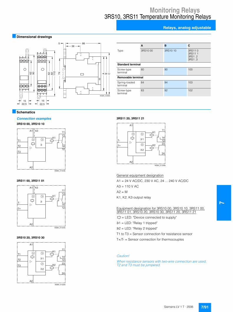
Monitoring Relays
7
3RS10, 3RS11 Temperature Monitoring Relays
Relays, analog adjustable
■ Dimensional drawings
■ Schematics
Connection examples
3RS10 00, 3RS10 10
3RS11 00, 3RS11 01
3RS10 20, 3RS10 30
3RS11 20, 3RS11 21
General equipment designation
A1 = 24 V AC/DC, 230 V AC, 24 ... 240 V AC/DC
A3 = 110 V AC
A2 = M
K1, K2, K3 output relay
Equipment designation for 3RS10 00, 3RS10 10, 3RS11 00,3RS11 01, 3RS10 20, 3RS10 30, 3RS11 20, 3RS11 21
= LED: "Device connected to supply"
�1 = LED: "Relay 1 tripped"
�2 = LED: "Relay 2 tripped"
T1 to T3 = Sensor connection for resistance sensor
T+/T- = Sensor connection for thermocouples
Caution!
When resistance sensors with two-wire connection are used, T2 and T3 must be jumpered.
NSB0_01606
A B C74
86536
62 90
1522,5
62 110
1522,5
82
A B C
Type 3RS10 00 3RS10 10 3RS11 03RS11 13RS1 .23RS1 .3
Standard terminal
Screw-type terminal
80 90 100
Removable terminal
Spring-loaded terminal
84 94 103
Screw-type terminal
83 92 102
��
�������
��
��
��
�
��
��
�
� ��
�
��
�������
��
��
��
��
��
�
�
��
�
A2NSB0_01335b
A1
T1
T2
T3
K111
14
23K2
12
24
1
2
��
��������
��
��
��
����
�
���
��
�
�
�
7/91Siemens LV 1 T · 2006
7Monitoring Relays
3RS10, 3RS11 Temperature Monitoring Relays
Relays, digitally adjustable to DIN 3440
■ Overview
The 3RS10/3RS11 temperature monitoring relays can be used for measuring temperatures in solid, liquid and gas media. The temperature is sensed by the sensor in the medium, evaluated by the device and monitored for overshoot or undershoot or for staying within an operating range (window function).
The 3RS10 40, 3RS20 40, 3RS11 40 and 3RS21 40 relays comply with the requirements of DIN 3440 as temperature monitors; the 3RS10 42 and 3RS11 42 relays comply with the requirements of DIN 3440 as temperature limiters. The relays are also an excellent alternative to temperature controls in the low-end performance range (2 or 3-point closed-loop control).
■ Technical specifications
1) Not for NTC B57227-K333-A1 (100 °C: 1.8 k; 25 °C: 32.762 k).
2) 2-wire connection of resistance sensors with wire jumper between T2 and T3.
3) See Catalog LV1, Accessories, 3RP15 Solid-State Timing Relays.
Type 3RS10 40/3RS10 42/3RS20 40 3RS11 40/3RS21 40 3RS11 42General dataWidth mm 45
Operating range V 0.85 ... 1.1 x Us
Rated power W/VA < 4/7Auxiliary circuitsContacts 1 CO + 1 CO + 1 NO
Rated operational currents Ie • AC-15 at 230 V AC, 50 Hz A 3• DC-13 at:
- 24 V AC A 1- 240 V AC A 0.1
DIAZED fuse gl/Gg operational class
A 4
Electrical endurance AC-15 at 3 A
A 100000
Mechanical endurance Mechanical operating cycles
30 x 106
Tripping units• Measuring accuracy at 20 °C ambient temperature
(T20)< �2 K, �1 digit < �5 K, �1 digit < �7 K, �1 digit
• Reference point accuracy -- < �5 K
• Deviations due to ambient temperature in % from measuring range
% 0.05 °C per K deviation from T20
• Measuring cycle ms 500
• Hysteresis settings - for temperature 1
1 ... 99 Kelvin, for both values
Adjustable delay time s 0 ... 999Sensor circuits • Typical sensor circuits
- PT100 mA Typical 1 - -- PT1000/KTY83/KTY84/NTC mA Typical 0.2 - -
• Open-circuit detection Yes1) Yes Yes
• Short-circuit detection Yes No No
• 3-wire conductor connection Yes2) - -EnclosuresEnvironmental influencesPermissible ambient temperature °C -25 ... +60Permissible storage temperature °C -40 ... +80Permissible mounting position any
Degree of protection acc. to EN 60529 Terminals: IP20; Cover: IP40
Rated insulation voltage Ui (pollution degree 3)
V AC 300
Conductor cross-section
• Screw-type connection M 3.5 (standard screwdriver, size 2 and Pozidriv 2)
- Solid mm2 1 x (0.5 ... 4)/2 x (0.5 ... 2.5)- Finely stranded, with end sleeve mm2 1 x (0.5 ... 2.5)/2 x (0.5 ... 1.5)- AWG conductors, solid or stranded AWG 2 x (20 ... 14)- Tightening torque Nm 0.8 ... 1.2
• Spring-loaded terminal - Solid mm2 2 x (0.25 ... 1.5)- Finely stranded, with end sleeve mm2 2 x (0.25 ... 1)- Finely stranded, without end sleeve mm2 2 x (0.25 ... 1.5)- AWG conductors, solid or stranded AWG 2 x (24 ... 16)- Corresponding opening tool 8WA2 8073)
Vibration resistance IEC 68-2-6 Hz/mm 5 ... 26/0.75
Shock resistance IEC 68-2-27 g/ms 15/11
7/92 Siemens LV 1 T · 2006

Monitoring Relays
7
3RS10, 3RS11 Temperature Monitoring Relays
Relays, digitally adjustable to DIN 3440
■ Dimensional drawings
■ Schematics
Connection examples
3RS10 40, 3RS10 42, 3RS20 40
3RS11 40, 3RS11 42, 3RS21 40
General equipment designation
A1, A2, A3 terminals for rated control supply voltage
K1, K2, K3 output relay
Item code
�1 = LED: "Relay 1 tripped"
�2 = LED: "Relay 2 tripped"
Ready = LED: "Device is ready for operation"
T1 to T3 = Sensor connection for resistance sensor
T+/T- = Sensor connection for thermocouples
Y1/Y2 connection for memory jumper for 3RS10 40, 3RS11 40, 3RS20 40, 3RS21 40 or Y3/Y4 Reset input for 3RS10 42, 3RS11 42
Caution!
When resistance sensors with two-wire connection are used, T2 and T3 must be jumpered.
� �� �
� � � � � � � �
�
� � �
�
� � �
�
A C
3RS10, 3RS11, 3RS20, 3RS21 digital
Removable terminal
Spring-loaded terminal 84 108
Screw-type terminal 83 106
� � � � � � � � � � �
�
�
� �
�
� �
�
� �
�
� � � �
� �
� �� �
� � � � � � �
� � � � �
� � � � �
� �� �
� � � � � � � � � �
�
� �
� !
� "
�
� �
�
� �� �
� �
� �� �
� �� �
� � � � � � �
� � � � �
� � � � �
7/93Siemens LV 1 T · 2006

7Monitoring Relays
3RS10, 3RS11 Temperature Monitoring Relays
Relays, digitally adjustable for up to 3 sensors
■ Overview
The 3RS10 41 temperature monitoring relays can be used for measuring temperatures in solid, liquid and gas media. The temperature is sensed by the sensor in the medium, evaluated by the device and monitored for overshoot or undershoot or for
staying within an operating range (window function). The signal evaluator can evaluate up to 3 resistance sensors at the same time and is specially designed for monitoring motor windings and bearings.
■ Technical specifications
1) Not for NTC B57227-K333-A1 (100 °C: 1.8 k; 25 °C: 32.762 k).
2) 2-wire connection of resistance sensors with wire jumper between T2 and T3.
3) See Catalog LV1, Accessories, 3RP15 Solid-State Timing Relays.
Type 3RS10 41General dataWidth mm 45
Operating range V 0.85 ... 1.1 x Us
Rated power W/VA < 4/7Auxiliary circuitsContacts 1 CO + 1 CO + 1 NO
Rated operational currents Ie • AC-15 at 230 V AC, 50 Hz A 3• DC-13 at:
- 24 V AC A 1- 240 V AC A 0.1
DIAZED fuse• gl/Gg operational class A 4
Electrical endurance AC-15 at 3 A A 100000
Mechanical endurance Mechanical operating cycles
30 x 106
Tripping units• Measuring accuracy at 20 °C ambient temperature
(T20)< �2 K, �1 digit
• Deviations due to ambient temperature in % from measuring range
% 0.05 per K deviation from T20
• Measuring cycle ms 500
• Hysteresis settings for temperature 1 1 ... 99 K, for both values
• Adjustable delay time s 0 ... 999Sensor circuits • Typical sensor circuits
- PT100 mA Typical 1- PT1000/KTY83/KTY84/NTC mA Typical 0.2
• Open-circuit detection Yes1)
• Short-circuit detection Yes
• 3-wire conductor connection Yes2)
EnclosuresEnvironmental influencesPermissible ambient temperature °C -25 ... +60Permissible storage temperature °C -40 ... +80Permissible mounting position any
Degree of protection acc. to EN 60529 Terminals: IP20; Cover: IP40
Rated insulation voltage Ui (pollution degree 3)
V AC 300
Conductor cross-section
• Screw-type connection M 3.5 (standard screwdriver, size 2 and Pozidriv 2)
- Solid mm2 1 x (0.5 ... 4)/2 x (0.5 ... 2.5)- Finely stranded, with end sleeve mm2 1 x (0.5 ... 2.5)/2 x (0.5 ... 1.5)- AWG conductors, solid or stranded AWG 2 x (20 ... 14)- Tightening torque Nm 0.8 ... 1.2
• Spring-loaded terminal - Solid mm2 2 x (0.25 ... 1.5)- Finely stranded, with end sleeve mm2 2 x (0.25 ... 1)- Finely stranded, without end sleeve mm2 2 x (0.25 ... 1.5)- AWG conductors, solid or stranded AWG 2 x (24 ... 16)- Corresponding opening tool 8WA2 8073)
Vibration resistance IEC 68-2-6 5 ... 26 Hz/0.75 mm
Shock resistance IEC 68-2-27 15 g/11 ms
7/94 Siemens LV 1 T · 2006
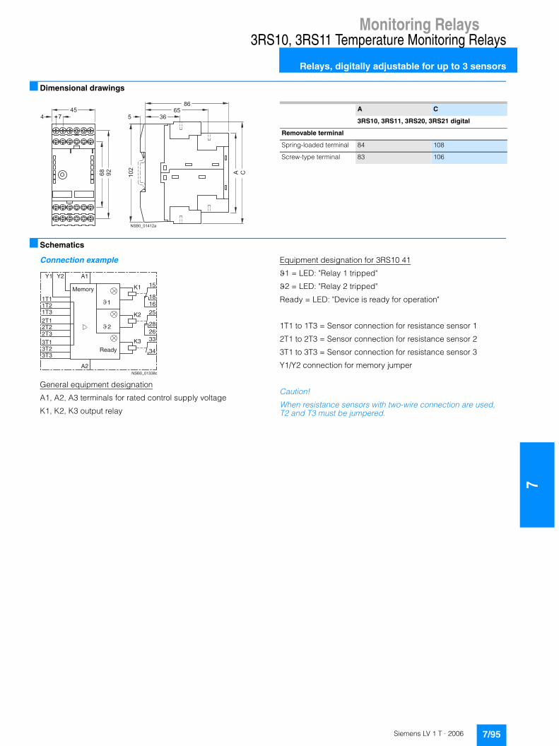
Monitoring Relays
7
3RS10, 3RS11 Temperature Monitoring Relays
Relays, digitally adjustable for up to 3 sensors
■ Dimensional drawings
■ Schematics
Connection example
General equipment designation
A1, A2, A3 terminals for rated control supply voltage
K1, K2, K3 output relay
Equipment designation for 3RS10 41
�1 = LED: "Relay 1 tripped"
�2 = LED: "Relay 2 tripped"
Ready = LED: "Device is ready for operation"
1T1 to 1T3 = Sensor connection for resistance sensor 1
2T1 to 2T3 = Sensor connection for resistance sensor 2
3T1 to 3T3 = Sensor connection for resistance sensor 3
Y1/Y2 connection for memory jumper
Caution!
When resistance sensors with two-wire connection are used, T2 and T3 must be jumpered.
� �� �
� � � � � � � �
�
� � �
�
� � �
�
A C
3RS10, 3RS11, 3RS20, 3RS21 digital
Removable terminal
Spring-loaded terminal 84 108
Screw-type terminal 83 106
A2NSB0_01338c
A1
K1 15
1618
K2 25
28
K3 33
34
26
Y2Y1
1T11T21T32T12T22T33T13T23T3
Memory
Ready
1
2
7/95Siemens LV 1 T · 2006

7Monitoring Relays
3RN1 Thermistor Motor Protection
For PTC sensors
■ Overview
Thermistor motor protection devices are used for direct monitoring of the motor winding temperature. For this purpose, the motors are equipped with temperature-dependent resistors
(PTC) that are directly installed in the motor winding and abruptly change their resistance at their limit temperature.
■ Design
The 3RN1 tripping units are suitable for use in any climate and finger-safe according to EN 0106 Part 50274. They comply with:• EN 61000-6-2 and EN 61000-6-4, "Electromagnetic
compatibility of I&C equipment in industrial process engineering"
• EN 60947-8
The terminals of the auxiliary contacts are designated in accordance with EN 50005.
The 3RN1 tripping units are suitable for snap-on mounting onto 35 mm standard mounting rails according to EN 50022 or for screw-mounting using an adapter (Accessories).
Any mounting position is possible.
For devices with the "Manual RESET" function, the test function can be activated and a trip simulated by pressing the blue Test/RESET button for longer than 2 seconds.
If a Type A temperature sensor is connected to a Type A tripping unit, compliance with the operating temperatures is assured (on pick-up and reset) according to IEC 60034-11-2 (EN 60947-8).
The characteristic curves of the Type A temperature sensors are described in EN 60947-8, DIN 44081 and DIN 44082.
Use in areas subject to explosion hazard for gases
All devices are approved for Equipment Group II, Category (2) in Area "G" (areas that contain explosive gases, vapor, spray and air mixtures).
With PTB 01 ATEX 3218 ex II (2) G, compliance with guideline 94/9 EG Appendix II is confirmed. The safety devices must be selected with suitable settings for the safe operation of motors of the "Increased safety" (EEx e) and "Flameproof enclosure" (EEx d) degrees of protection and are accessed outside the area subject to explosion hazard.
PTB 01 ATEX 3218 ex II (2) G
The increased danger in areas subject to explosion hazard demands careful analysis of the operator's guide, the safety and commissioning instructions and the standard (EN 60079-14/VDE 0165) for electronic equipment in areas subject to gas explosion hazards.
A risk analysis must be performed for the complete plant or machine. If this risk analysis results in a minimal potential for danger (Safety Category 1), all 3RN1 TMS tripping units can be implemented taking into account the safety notes. In the case of plants or machines with a high potential risk, variants with integrated short-circuit detection in the sensor circuit are necessary.
Use in areas subject to explosion hazard for dust
PTB 01 ATEX 3218 ex II (2) G
3RN10 11-.B/-.G, 3RN10 12-.B/-.G and 3RN10 13-...0 tripping units can be used as safety devices for motors in areas subject to gas explosion hazard for protection against impermissible overheating due to overload. If the ATEX marking has the extension "D:=Dust", these units can also be used as protective devices for motors in areas subject to dust explosion hazard (EN 50281-1-1).
Additional information is provided in the EU type test certificate which can be obtained from the Internet. The units comply with the requirements of the following classes:
The measuring circuit leads must be routed as separate control leads. It is not permitted to use cores from the supply line of the motor or any other main supply cables. If extreme inductive or capacitive interference is expected as a result of power lines routed in parallel, shielded control leads must be used.
4000
1330
550
250
20
-20°C 0 TNF-20TNF-5
TNF TNF+15 T
R
NSB00320
TNF+5
Device Class
3RN10 00, 3RN10 10, 3RN10 11-.C, 3RN10 12-.C, 3RN10 22, 3RN10 62
EN 954-1: Category 1
3RN10 11-.B, 3RN10 11-.G, 3RN10 12-.B, 3RN10 12-.G, 3RN10 13
EN 954-1: Category 2
7/96 Siemens LV 1 T · 2006

Monitoring Relays
7
3RN1 Thermistor Motor Protection
For PTC sensors
Cable routing
Maximum cable length for sensor circuit cables
1) A short-circuit in the sensor circuit will be detected up to this maximum cable length.
Notes:
Tripping of the thermistor protection relay even in combination with a converter must directly result in disconnection. This must be implemented with circuitry.
Mounting and installation must only be performed by qualified personnel who observe the applicable regulations! For mounting, use installation manual No.: 3ZX1012-0RN10-1AA1.
The 3RN10 is not intended for installation in hazardous areas. For installation in areas subject to explosion hazards, the 3RN10 must be enclosed in a flameproof casing.
For tripping units with a 24 V AC/DC control voltage, electrical isolation must be secured with a battery network or a safety transformer according to DIN VDE 0551.
When tripping units with Auto-RESET function are used, a reset is performed automatically after the cooling time has expired. It must be ensured by means of an external interlock (latching with a separate On and Off button) that the machine to be monitored does not start up again spontaneously.
Units with the Auto-RESET function must not be used in applications in which the unexpected restart can lead to personal injury or property damage.
In the case of tripping units without short-circuit detection, during commissioning or after modifications or maintenance work (assembly, disassembly) on the equipment, the sensor resistance must be measured using a suitable measuring instrument. For resistances < 50 Ohm, the sensor circuit must be checked for a short-circuit.
If 3RN10 00 units are used to protect EEx e motors, separate monitoring of the control voltage is recommended because there is no Ready LED to indicate connection to the supply voltage.
If 3RN10 13-.BW01 units are used to protect EEx e motors, separate monitoring of the control voltage is recommended because the switching status of the auxiliary contacts does not change if the control voltage fails (use of a bistable relay is recommended).
Before commissioning, the effectiveness of the protection function must be checked.
■ Function
The 3RN1 tripping units operate in accordance with the closed-circuit principle and therefore monitor themselves for open-circuit (except: warning output in the case of 3RN10 22). A momentary power failure of less than 50 ms does not change the status of the auxiliary contacts. The 3RN10 11, 3RN10 12 and 3RN10 13 units with 2 changeover contacts are also equipped with short-circuit detection in the sensor circuit. The unit will trip in the event of a short-circuit in the sensor circuit (resistance in sensor circuit < 20 �).
All tripping units (except for 24 V AC/DC ) feature electrical isolation between the control circuit and the sensor circuit.
3RN10 00 compact tripping units
The compact tripping unit is equipped with a red LED (TRIPPED) for the tripped display and a changeover contact.
After the unit has tripped, it is automatically reset once the thermistors have cooled down. The root of the changeover contact is connected to the control voltage (95 is connected to terminal A1).
This unit is particularly suitable in circuits in which the control circuit and signaling circuit have the same potential, e.g. in local control boxes.
3RN10 10, 3RN10 11, 3RN10 12, 3RN10 13 standard tripping units
The standard units are equipped with two LEDs (READY and TRIPPED) for an operating and tripped display and are available with either 1 NO + 1 NC or with 2 CO contacts. They are available depending on the version with automatic RESET (3RN10 10), manual/remote RESET (3RN10 11) or manual/automatic and remote RESET (3RN10 12 and 3RN10 13). Remote RESET can be achieved by connecting an external pushbutton with a normally-open function to terminals Y1 and Y2. If terminals Y1 and Y2 are bridged, tripping will be followed by an automatic RESET.
The 3RN10 11, 3RN10 12 and 3RN10 13 units with 2 COs also have short-circuit monitoring in the sensor circuit.
The 3RN10 12 and the 3RN10 13 are non-volatile. This means that even if the control voltage fails, a preceding trip will be latched.
In the case of the 3RN10 13 tripping unit, tripping due to a short-circuit in the sensor circuit will be indicated by a flashing red LED. The monostable version also indicates open-circuit in the sensor circuit by flashing of the red LED.
3RN10 22 "Warning and disconnection" tripping units
Two sensor circuits can be connected to one 3RN10 22 tripping unit that acts on one output relay with 1 NO contact for warning and 1 CO for disconnection. Temperature sensors with different rated response temperatures TNF are used to implement the "Warning" and "Disconnection" functions. When the "Warning" sensor circuit responds, a yellow LED is lit and when the "Disconnection" circuit responds, a red LED is lit.
The sensor circuits have a different reset response and operating behavior:• "Warning" (terminals 2T1, T2) only features automatic RESET
and uses the open-circuit principle.• "Disconnection" (terminals 1T1, T2) can be changed from
manual RESET to automatic RESET by linking terminals Y1 and Y2. Remote RESET is implemented by connecting an external pushbutton with a normally-open function.
Conductor cross-section in mm2
Cable length in m for tripping units
Without short-circuit detection3RN10 00, 3RN10 103RN10 11-.C3RN10 12-.C3RN10 22, 3RN10 62
With short-circuit detection1)
3RN10 11-.B/-.G3RN10 12-.B/-.G3RN10 13
2.5 2 x 2800 2 x 250
1.5 2 x 1500 2 x 150
0.5 2 x 500 2 x 50
7/97Siemens LV 1 T · 2006
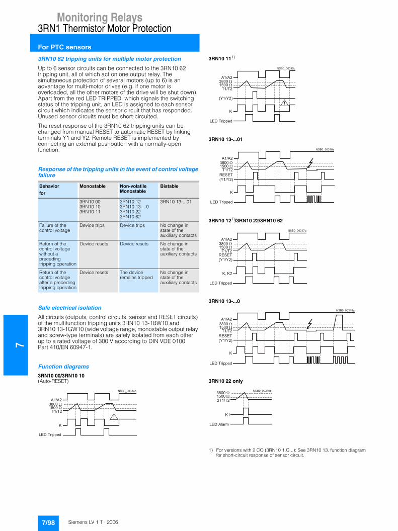
7Monitoring Relays
3RN1 Thermistor Motor Protection
For PTC sensors
3RN10 62 tripping units for multiple motor protection
Up to 6 sensor circuits can be connected to the 3RN10 62 tripping unit, all of which act on one output relay. The simultaneous protection of several motors (up to 6) is an advantage for multi-motor drives (e.g. if one motor is overloaded, all the other motors of the drive will be shut down). Apart from the red LED TRIPPED, which signals the switching status of the tripping unit, an LED is assigned to each sensor circuit which indicates the sensor circuit that has responded. Unused sensor circuits must be short-circuited.
The reset response of the 3RN10 62 tripping units can be changed from manual RESET to automatic RESET by linking terminals Y1 and Y2. Remote RESET is implemented by connecting an external pushbutton with a normally-open function.
Response of the tripping units in the event of control voltage failure
Safe electrical isolation
All circuits (outputs, control circuits, sensor and RESET circuits) of the multifunction tripping units 3RN10 13-1BW10 and 3RN10 13-1GW10 (wide voltage range, monostable output relay and screw-type terminals) are safely isolated from each other up to a rated voltage of 300 V according to DIN VDE 0100 Part 410/EN 60947-1.
Function diagrams
3RN10 00/3RN10 10 (Auto-RESET)
3RN10 111)
3RN10 13-...01
3RN10 121)/3RN10 22/3RN10 62
3RN10 13-...0
3RN10 22 only
1) For versions with 2 CO (3RN10 1.G...): See 3RN10 13. function diagram for short-circuit response of sensor circuit.
Behavior
for
Monostable Non-volatileMonostable
Bistable
3RN10 003RN10 103RN10 11
3RN10 123RN10 13-...03RN10 223RN10 62
3RN10 13-...01
Failure of the control voltage
Device trips Device trips No change in state of the auxiliary contacts
Return of the control voltage without a preceding tripping operation
Device resets Device resets No change in state of the auxiliary contacts
Return of the control voltage after a preceding tripping operation
Device resets The device remains tripped
No change in state of the auxiliary contacts
�����
�����
������� �
�����������
��������
�
� � � � �
� � � � �
� � � � � � �
� � � � � � � �
� � � �� � � �
�
� � � � � � � � � � �
���������
�����
��� �� ��
�����������
����
�
����������
�����
�������� �� ��
�����������
��������
�����
����������
�����
�����
��� �� ��
�����������
��������
�
����������
������
���� ��!
���������"#��������
��
7/98 Siemens LV 1 T · 2006
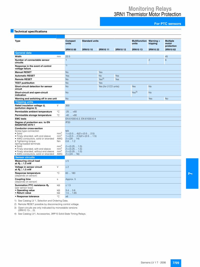
Monitoring Relays
7
3RN1 Thermistor Motor Protection
For PTC sensors
■ Technical specifications
1) See Catalog LV 1, Selection and Ordering Data.
2) Remote RESET possible by disconnecting control voltage.
3) Open-circuits are only indicated by monostable versions(3RN10 13-....0).
4) See Catalog LV1, Accessories, 3RP15 Solid-State Timing Relays.
Type Compact units
Standard units Multifunction units
Warning + tripping
Multiple motor protection
3RN10 00 3RN10 10 3RN10 11 3RN10 12 3RN10 13 3RN10 22 3RN10 62General dataWidth mm 22.5 45
Number of connectable sensor circuits
1 2 6
Response in the event of control voltage failure
1)
Manual RESET No Yes
Automatic RESET Yes No Yes
Remote RESET No Yes2) Yes
TEST pushbutton No Yes
Short-circuit detection for sensor circuit
No Yes (for 2 CO units) Yes No
Short-circuit and open-circuit indication
No Yes3) No
Warning and switching off in one unit No Yes NoTripping unitsRated insulation voltage Ui (pollution degree 3)
V 300
Permissible ambient temperature °C -25 … +60
Permissible storage temperature °C -40 … +80
EMC tests EN 61000-6-2, EN 61000-6-4
Degree of protection acc. to EN 60529/VDE 0470-1
IP20
Conductor cross-sectionScrew-type connection M3• Solid mm2 1 x (0.5 ... 4)/2 x (0.5 ... 2.5)• Finely stranded, with end sleeve mm2 1 x (0.5 ... 2.5)/2 x (0.5 ... 1.5)• AWG conductors, solid or stranded AWG 2 x (20 ... 14)• Tightening torque Nm 0.8 ... 1.2Spring-loaded terminals• Solid mm2 2 x (0.25 ... 1.5)• Finely stranded, with end sleeve mm2 2 x (0.25 ... 1.5)• Finely stranded, without end sleeve mm2 2 x (0.25 ... 1.5)• AWG conductors, solid or stranded AWG 2 x (24 ... 16)Sensor circuits Measuring circuit load at RF � 1.5 mW
� 5
Voltage in sensor circuit at RF � 1.5 mW
V � 2
Response temperature (depends on sensor)
°C 60 ... 180
Coupling time (depends on sensor)
s Approx. 5
Summation PTC resistance RF (per sensor loop)
k� � 1.5
• Operating value k� 3.4 ... 3.8• Return value k� 1.5 ... 1.65
• Response tolerance °C �6
7/99Siemens LV 1 T · 2006

7Monitoring Relays
3RN1 Thermistor Motor Protection
For PTC sensors
1) See Catalog LV 1, Selection and Ordering Data. 2) 2 A for 3RN10 13-.BW01 (bistable output relays).
3) In > 1 kA weld-free acc. to EN 60947-5-1.
■ Dimensional drawings
3RN1. with 1 ... 2 sensor circuits
3RN10 62
Type Compact units
Standard units Multifunction units
Warning + tripping
Multiple motor protection
3RN10 00 3RN10 10 3RN10 11 3RN10 12 3RN10 13 3RN10 22 3RN10 62Control circuitsRated control supply voltage Us
1)
Operating range 110 V/230 V AC 0.85 ... 1.1 x Us• 24 V ... 240 V AC/DC 0.85 ... 1.1 x Us• 24 V AC/DC 0.85 ... 1.2 x Us for DC operation, 0.85 ... 1.1 x Us for AC operation
Rated power• AC W < 2• AC/DC W < 2• DC W < 2
Max. mains buffering time ms 50Auxiliary circuitsContinuous thermal current Ithe A 5
Rated operational current Ie • AC-15 240 V A 3• DC-13 24 V A 1 for units with 1 CO or 2 COs
2 for units with 1 NC + 1 NO12) 1 2
DIAZED fuse A 63)
CSA and UL rated data, control circuitRated control voltage 50/60 Hz• AC V 300• DC V 300
Switching capacity R 300/B 300
Safe isolation up to 300 Vacc. to DIN 60 947-1
-- 3RN10 13-1BW10
--
A B C
3RN10 00 3RN10 00 3RN10 113RN10 123RN10 133RN10 22
Removable terminal
Spring-loaded terminal
84 94 103
Screw-type terminal
83 92 102
NSB0_01606
A B C74
86536
62 90
1522,5
62 110
1522,5
82
A C
3RN10 62
Standard terminal
Spring-loaded terminal 84.3 107.6
Screw-type terminal 81 104
Removable terminal
Spring-loaded terminal 84 108
Screw-type terminal 83 106
� �� �
� � � � � � � �
�
� � �
�
� � �
�
7/100 Siemens LV 1 T · 2006

Monitoring Relays
7
3RN1 Thermistor Motor Protection
For PTC sensors
■ Schematics
Connection diagrams
1) For units with combination voltages 230 V/110 V AC (3RN10 11-.CK00 and 3RN10 12-.CK00) the following applies: A1 and A2: 230 V AC, A3 and A2: 110 V AC.
Illustrated with control voltage applied
Illustrated with control voltage not applied
Illustrated with control voltage applied
Illustrated with control voltage not applied
3RN10 00, 1 CO
3RN10 10, 1 NO + 1 NC 3RN10 10, 2 COs
3RN10 111), 1 NO + 1 NC 3RN10 11, 2 COs
3RN10 121), 1 NO + 1 NC 3RN10 12, 2 COs
3RN10 13-...0 (monostable)
3RN10 13-...1 (bistable)
3RN10 22
3RN10 62
General equipment designation
A1, A2, A3
NT/RY1, Y2
Connections of the control voltageAmplifierTEST/RESET buttonConnections for remote RESET (jumpered = Auto-RESET)The double arrow indicates an operating status which deviates from the standard representation of the contact acc. to DIN 40900, Part 7(in this case: Position of the contacts when control voltage is applied to terminals A1 and A2)
Equipment designation for 3RN10
H1H2KT1, T2
"READY" LED"TRIPPED" LEDOutput relayConnections of the sensor loop
Equipment designation for3RN10 22
H1H2H3K1, K21T1 and T22T1 and T2
"READY" LED "TRIPPED" LED"ALARM" LEDOutput relayConnections of thesensor loop
. Important!
Close unconnected sensor circuits.
Equipment designation for 3RN10 62
H1 to H6
H7H8K1T1, 1T2to6T1, 6T2
LED for the tripped sensor loop"READY" LED"TRIPPED" LEDOutput relayConnections of thefirst sensor loopConnections of thesixth sensor loop
. Important!
Close unconnected sensor circuits.
�����
�� �� �� �� �
�� �
��� �������������
�� ���
96 98T1 T2 A2
95 97A1
(14) (22)
(13) (21)
NSB0_00323b
H1
N H2 K
T/R
�� �� �� �
�� ��
�� �� �
��
�� �
���
��� ���
���������
��� ��� ���
��
96 98T1 T2 A2
95 97A1
(14) (22)
(13) (21)
NSB0_00323b
H1
N H2 K
T/R
��
���
�� �� �
�� ��
�� �� �
��
�� �
���
��� ���
��������
��� ��� ���
��
�� �
�� ���� �� �� �����
�� �
�� �� ��
���
��� ���
��� ���
����������
T1
T/R
A2 96 98
95
T2 06 08
05
H2 K
(14)
(11) (21)
NSB0_01399a
(12) (24) (22)
H1
N
Y1 Y2 A1
��
���
�� �� �
�� �� �� ��
�� �� �
��
�� �
���
��� ���
���������
��� ��� ���
��
��
���
�� �� �
�� �� �� ��
�� �� �
��
�� �
���
��� ���
���������
��� ��� ���
��
�� �� �� ��
� ��� ��� ��� �� �� �� �
��
��
��
�� ��
���
�� ���
��� ������������
���
�� ��
�
���
������ ��� ��
�� �� ��
��� �
��
��
� �
� �
��� ��� ��� ��������������� ��� �� ��� ���
��� ���
����������
7/101Siemens LV 1 T · 2006
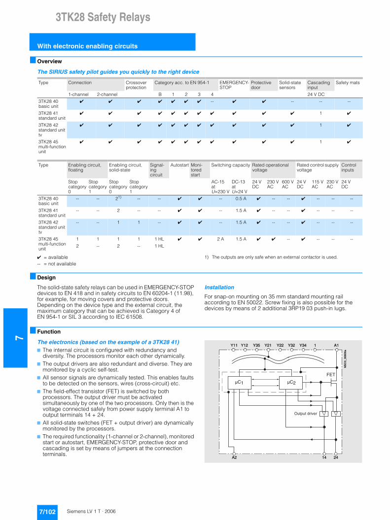
73TK28 Safety Relays
With electronic enabling circuits
■ Overview
The SIRIUS safety pilot guides you quickly to the right device
✔ = available-- = not available
1) The outputs are only safe when an external contactor is used.
■ Design
The solid-state safety relays can be used in EMERGENCY-STOP devices to EN 418 and in safety circuits to EN 60204-1 (11.98), for example, for moving covers and protective doors. Depending on the device type and the external circuit, the maximum category that can be achieved is Category 4 of EN 954-1 or SIL 3 according to IEC 61508.
Installation
For snap-on mounting on 35 mm standard mounting rail according to EN 50022. Screw fixing is also possible for the devices by means of 2 additional 3RP19 03 push-in lugs.
■ Function
The electronics (based on the example of a 3TK28 41)7 The internal circuit is configured with redundancy and
diversity. The processors monitor each other dynamically.7 The output drivers are also redundant and diverse. They are
monitored by a cyclic self-test.7 All sensor signals are dynamically tested. This enables faults
to be detected on the sensors, wires (cross-circuit) etc.7 The field-effect transistor (FET) is switched by both
processors. The output driver must be activated simultaneously by one of the two processors. Only then is the voltage connected safely from power supply terminal A1 to output terminals 14 + 24.
7 All solid-state switches (FET + output driver) are dynamically monitored by the processors.
7 The required functionality (1-channel or 2-channel), monitored start or autostart, EMERGENCY-STOP, protective door and cascading is set by means of jumpers at the connection terminals.
Type Connection Crossover protection
Category acc. to EN 954-1 EMERGENCY-STOP
Protective door
Solid-state sensors
Cascading input
Safety mats
1-channel 2-channel B 1 2 3 4 24 V DC
3TK28 40 basic unit
✔ ✔ ✔ ✔ ✔ ✔ ✔ -- ✔ ✔ -- -- --
3TK28 41 standard unit
✔ ✔ ✔ ✔ ✔ ✔ ✔ ✔ ✔ ✔ ✔ 1 ✔
3TK28 42 standard unit tv
✔ ✔ ✔ ✔ ✔ ✔ ✔ ✔ ✔ ✔ ✔ 1 ✔
3TK28 45 multi-function unit
✔ ✔ ✔ ✔ ✔ ✔ ✔ ✔ ✔ ✔ ✔ 1 ✔
Type Enabling circuit, floating
Enabling circuit, solid-state
Signal-ing circuit
Autostart Moni-tored start
Switching capacity Rated operational voltage
Rated control supply voltage
Control inputs
Stop category 0
Stop category 1
Stop category 0
Stop category 1
AC-15atU=230 V
DC-13atU=24 V
24 V DC
230 V AC
600 V AC
24 V DC
115 V AC
230 V AC
24 V DC
3TK28 40 basic unit
-- -- 21) -- -- ✔ ✔ -- 0.5 A ✔ -- -- ✔ -- -- --
3TK28 41 standard unit
-- -- 2 -- -- ✔ ✔ -- 1.5 A ✔ -- -- ✔ -- -- --
3TK28 42 standard unit tv
-- -- 1 1 -- ✔ ✔ -- 1.5 A ✔ -- -- ✔ -- -- --
3TK28 45 multi-function unit
1 1 1 1 1 HL ✔ ✔ 2 A 1.5 A ✔ ✔ -- ✔ -- -- --
2 -- 2 -- 1 HL
'�� '�� '�� '�� '�� '�� '�� ��
�� �� ��
D�� D��
#��
����+
���
,�
�86>,.>6127-E72
'�� '�� '�� '�� '�� '�� '�� ��
�� �� ��
D�� D��
#��
����+
���
,�
"81981�<2-:72
7/102 Siemens LV 1 T · 2006
3TK28 Safety Relays
7
With electronic enabling circuits
■ Technical specifications
1) Electrical equipment for furnaces. VDE certificate for 3TK28 41 and 3TK28 42 is available.
2) For relay outputs, use a fuse link: LV HRC Type 3NA, DIAZED Type 5SB, NEOZED Type 5SE: 6 A (weld-free protection at IK = 1 kA).
3) For instantaneous output.
4) When the cascading input is supplied from A1, the maximum response time is applicable to an external EMERGENCY-STOP.
5) The drivers are not supplied, internal supply bridging only. SELV/PELV power supply unit buffered.
Type 3TK28 40 3TK28 41 3TK28 42 3TK28 45
Standards EN 60204-1 (VDE 0113 Part 1), EN ISO 12100, EN 954-1, IEC 61508, DIN VDE 01161)
Category acc. to EN 954-1 3 4 4 4
Test certificates TÜV, UL, CSA
Rated insulation voltage Ui• For control circuit V 50 50 50 50• For outputs V 50 50 50 50/300
Rated impulse withstand voltage Uimp• For control circuit V 500 500 500 500• For outputs V 500 500 500 500/2000
Operating range• DC operation 0.9 ... 1.15 × Us
Rated operational currents Ie acc. to IEC 60947-5-1
• Ie/AC-15 at 115 V A -- -- -- 2at 230 V A -- -- -- --
• Ie/ DC-13 at 24 V A 0.5 1.5 1.5 1.5
Short-circuit protection Short-circuit proof Short-circuit proof2)
Electrical endurance Unlimited, because switched electronically
Operating frequency zin operating cycles/h during normal duty 1/h 3000
Response time• Monitored start ms 125 60 60 60• Autostart ms 250 60 60 60
release time• For EMERGENCY-STOP ms 30 45 453)/0.05 ... 300 s
(adjustable)453)/0.05 ... 300 s(adjustable)
• For supply failure ms 25 1004) 1004) 100
Recovery time• For EMERGENCY-STOP ms 20 400 400 400• For supply failure s 0.02 max. 7 max. 7 max. 7
Bridging of supply failures ms 255) 254)5) 254)5) 255)
Minimum command duration• EMERGENCY-STOP ms 20 25 30 30• ON button s 0.02 0.2 ... 5 0.2 ... 5 0.2 ... 5
Simultaneity ms
Conductor cross-sections
Screw-type connection• Finely stranded with end sleeve mm2 2 × (0.5 ... 1.5), 1 × (0.5 ... 2.5)• Solid mm2 2 × (0.5 ... 2.5), 1 × (0.5 ... 4)• Tightening torque Nm 0.8 ... 1.2
Spring-loaded terminals (1 or 2 conductors can be connected)• Solid mm2 2 × (0.25 ... 1.5)• Finely stranded with end sleeve mm2 2 × (0.25 ... 1.0)• Finely stranded without end sleeve mm2 2 × (0.25 ... 1.5)• AWG conductors, solid or stranded 2 × AWG 24 ... 16
Permissible ambient temperature• During operation °C –25 ... +60• During storage °C –40 ... +80
Degree of protection acc. to EN 60529• Enclosures IP40• Terminals IP20
Touch protection acc. to DIN VDE 0106 Part 100 Finger-safe
Shock resistance• Sinewave g/ms 8/10 and 15/5
Permissible mounting position Any
7/103Siemens LV 1 T · 2006
73TK28 Safety Relays
With electronic enabling circuits
■ Dimensional drawings
3TK28 with screw-type terminals
3TK28 40 to 3TK28 42
3TK28 45
1) For 35 mm standard mounting rail acc. to EN 50002.
3TK28 with spring-loaded terminals
3TK28 40 to 3TK28 42
3TK28 45
8665
365
10
2
83 9
2
12
0
87
68 74
74
1523
11
0
NSC0_00678
13
9
91
68
11
8
NSC0_00672
37
45115
9465
74
10
2
10
68
3
5
22,55 86
10
5
86
967
4
15
12
0
94
75
11
0
72,5NSC0_00677
5
75
37
45
73
98
13
911
8
10
2
115
86
11
0
NSC0_00673
7/104 Siemens LV 1 T · 2006
3TK28 Safety Relays
7
With relay enabling circuits
■ Overview
The SIRIUS safety pilot guides you quickly to the right device
1) Only possible for instantaneous enabling contacts. 2) The ON button is not monitored.
■ Design
The 3TK28 21 to 28, 3TK28 30 and 3TK28 34 safety relays operate with internal contactor relays with positively-driven contacts. The contacts of the controls comply with the requirement for positively driven operation laid down in ZH 1/457, Edition 2, 1978. NO and NC contacts are not allowed to be closed at the same time.
In a redundant circuit, operation of the internal controls is monitored. If a safety relay fails, it will always switch to the de-energized and consequently safe state. The fault is detected and the safety relay can no longer be switched on. The use of NO and NC contacts for the same function satisfies the demand for diversity.
This product series is characterized by its space-saving width (22.5 mm or 45 mm). The usual BIA, BG and SUVA approvals and test certificates have been awarded.
Enabling contacts (FK)
Safety related operation must be performed by safe output contacts, known as enabling contacts. Enabling contacts are always NO contacts and switch without delay.
Signaling contacts (MK)
NC contacts are used as signaling contacts but they are not permitted to perform functions with relevance for safety. An enabling contact can also be used as a signaling contact. A signaling contact cannot, however, be used as an enabling contact.
Delayed enabling contacts
Machine drives that overrun for a long time must be externally braked in the event of danger. For this purpose, the power supply for electrical braking can be maintained (Stop Category 1 according to EN 60204-1).
The basic units have off-delay enabling contacts in addition to instantaneous enabling contacts. Time delays of between 0.5 and 30 s are available with the different versions. A 3RP19 02 sealable covering cap (see Catalog LV 1, Selection and ordering data, Accessories) can be fitted to protect against unauthorized adjustment of the set delay time.
Expansion units
If the enabling contacts of the basic unit are inadequate, expansion units can be used. An expansion unit has 4 enabling contacts.
Expansion units are not allowed to be operated separately in safety-related switching circuits; they must be combined with a basic unit. One enabling contact of the basic unit is required for connecting an expansion unit. The category of a control system with expansion unit corresponds to that of the basic unit.
Installation
The equipment is designed for snap-on mounting on a 35 mm standard mounting rail to EN 50022. Screw fixing is also possible for the devices by means of 2 additional 3RP19 03 push-in lugs.
Type 1-channel connection
2-channel connection
Crossover protection
Categoryacc. to EN 954-1
EMER-GENCY-STOP
Protective door
Enabling contacts
Signaling contacts
Autostart Monitored start
B 1 2 3 4
Basic units3TK28 21 ✔ ✔ ✔ ✔ ✔ ✔ ✔ -- ✔ ✔ 3 NO 1 NC ✔ --
3TK28 22 -- ✔ ✔ ✔ ✔ ✔ ✔ ✔ ✔2) ✔ 2 NO -- ✔ --
3TK28 23 -- ✔ ✔ ✔ ✔ ✔ ✔ ✔ ✔ -- 2 NO -- -- ✔
3TK28 24 ✔ ✔ ✔ ✔ ✔ ✔ ✔ -- ✔ ✔ 2 NO -- ✔ –
3TK28 25 ✔ ✔ ✔ ✔ ✔ ✔ ✔ ✔ ✔ ✔ 3 NO 2 NC ✔ ✔
3TK28 27 ✔ ✔ ✔ ✔ ✔ ✔ ✔ 1) ✔ -- 2 NO +2 NO,delayed
1 NC -- ✔
3TK28 28 ✔ ✔ ✔ ✔ ✔ ✔ ✔ 1) ✔ ✔ 2 NO +2 NO,delayed
1 NC ✔ --
Expansion devices (category as for basic unit)3TK28 30 -- -- ● ● ● ● ● ● -- -- 4 NO -- -- --
Press control devices (acc. to EN 574)3TK28 34 -- ✔ ✔ ✔ ✔ ✔ ✔ ✔ -- -- 2 NO + 2 NC -- -- --
3TK28 35 -- -- -- ✔ ✔ ✔ ✔ ✔ -- -- 3 NO + 1 NC -- -- --
✔ = available
-- = not available
● = corresponds to basic unit
7/105Siemens LV 1 T · 2006
73TK28 Safety Relays
With relay enabling circuits
■ Technical specifications
1) Only applicable for instantaneous enabling contacts; Category 3 applies for time-delayed contacts.
2) Signaling circuit for 3TK28 21 = 6 A.
3) Other fuses on request.
4) Instantaneous/time-delayed enabling contacts.
5) 2 A applies to enabling contacts 13/14.
6) At 24 V AC: 300 ms.
7) At 115, 230 V AC: 300 ms.
8) At 115, 230 V AC: max. 200 ms.
9) At 115, 230 V AC: max. 80 ms.
Type 3TK28 21 3TK28 22 3TK28 23 3TK28 24 3TK28 30 3TK28 25 3TK28 27, 3TK28 28
3TK28 34 3TK28 35
Standards EN 60204-1 (VDE 0113 Part 1), EN ISO 12100, EN 954-1 Also EN 574
Test certificates BG, SUVA, UL, CSA
Category• Acc. to EN 954-1 3 4 4 3 As basic
unit4 41) 4 As basic
unit• Acc. to EN 574 -- -- -- -- -- -- Type III C
Rated insulation voltage Ui V 300Degree of pollution 3Overvoltage category acc. to EN 60664 III
Rated impulse withstand voltage Uimp kV 4
Rated power of coilsDC/AC operation at 1.0 × Us W 1.5 3 4 3
Operating range of the coils• AC operation 0.85 ... 1.1 × Us 0.85 ... 1.1 × Us• DC operation 0.85 ... 1.2 × Us 0.85 ... 1.1 × Us
Continuous thermal current Ith A 5 6 5 6 5
Continuous thermal current Ithfor 2 to 4 enabling contacts (FK)
• At AT 70 °C A 5 4 5 4• At AT 60 °C A 6 5 6 5• At AT 50 °C A 6 5 6 5
Rated operational currents Ie acc. to IEC 60947-1
• Ie / AC-15 at 115 V A 5 6 5/24) 6 5/25)
at 230 V A 5 6 5/24) 6 5/25)
• Ie / DC-13 at 24 V A 5 6 5/24) 6 5/25)
Short-circuit protection Fuse inserts LV HRC Type 3NA, DIAZED Type 5SB, NEOZED Type 5SE: 6 A(weld-free protection at Ik = 1 kA) 3) gL/gG operational class 6 A (slow), quick 10 A2)
Mechanical endurance 10 million operating cycles
Electrical endurance at Ie 100000 operating cycles
Switching frequency 1000/h on loading with IeResponse time ms � 308) � 100 � 50• Monitored start ms -- -- � 30 -- -- � 25 � 80 -- --• Autostart ms � 2006) � 100 -- � 2006)7) -- � 150 � 80 -- --
Release time ms � 20 � 50• For EMERGENCY-STOP ms � 200 � 80 � 20 � 200 – � 25 � 25 -- --• For supply failure ms � 200 � 100 � 150 � 200 � 259) � 350 � 100 -- --
Recovery time ��250 ��250• For EMERGENCY-STOP ms ��200 ��200 ��400 ��200 -- ��200 After time
has elapsed-- --
• For supply failure ms ��200 ��200 ��600 ��200 ��100 ��500 � 1 s -- --
Bridging of supply failures ms 60 30 80 60 35 100 30 40 40
Minimum command duration• EMERGENCY-STOP ms ��200 ��25 ��25 � 2007) -- � 25 � 25 -- --• ON button ms � 150 � 40 � 25 � 1507) -- � 25 � 25 -- --
Simultaneity ms 500
Conductor cross-sections
Screw-type connection• Finely stranded with end sleeve mm2 2 × (0.5 ... 1.5), 1 × (0.5 ... 2.5)• Solid mm2 2 × (0.5 ... 2.5), 1 × (0.5 ... 4)• Tightening torque, M 3.5 screw Nm 0.8 ... 1.2
Spring-loaded terminals (1 or 2 conductors can be connected)• Solid mm2 2 × (0.25 ... 1.5)• Finely stranded with end sleeve mm2 2 × (0.25 ... 1.0)• Finely stranded without end sleeve mm2 2 × (0.25 ... 1.5)• AWG conductors, solid or stranded 2 × AWG 24 ... 16
Permissible ambient temperature• During operation °C –25 ... +60 (suitable for butt-mounting; 70 °C possible with restrictions)• During storage °C –40 ... +80
Degree of protection acc. to EN 60529• Enclosures IP40 IP20• Terminals IP20 IP20
Touch protection acc. to VDE 0106 Finger-safe
Shock resistance, half-sine acc. to IEC 60068 8 g/10 ms
Permissible mounting position Any
2 FK 3 FK 4 FK
4 3.5 34.5 4 3.55 4.5 4
7/106 Siemens LV 1 T · 2006

3TK28 Safety Relays
7
With relay enabling circuits
■ Dimensional drawings
3TK28 (relay type) with screw terminals
3TK28 21 to 3TK28 24, 3TK28 30
3TK28 25, 3TK28 27, 3TK28 28, 3TK28 34, 3TK28 35
1) For 35 mm standard mounting rail acc. to EN 50022
3TK28 (relay type) with spring-loaded terminals
3TK28 21 to 3TK28 24, 3TK28 30
3TK28 25, 3TK28 27, 3TK28 28, 3TK28 34, 3TK28 35
23
15
NSC0_00671
12
0
87
68
74
11
0
11594
655
74
10
28
3
13
9
91
68
11
8
NSC0_00672
37
45115
9465
74
10
2
10
68
3
5
22,5
15
NSC0_00674
12
0
93
74
74
11
0
1155
72,4
10
384
5
75
37
45
73
98
13
911
8
10
2
115
86
11
0
NSC0_00673
7/107Siemens LV 1 T · 2006
73TK28 Safety Relays
With contactor relay enabling circuits
■ Overview
The SIRIUS safety pilot guides you quickly to the right device
✔ = available-- = not available● = corresponds to basic unit
Type Connection Crossover protection
Category acc. to EN 954-1 EMERGENCY-STOP
Protective door
Solid-state sensors
Cascading input
Safety mats
1-channel 2-channel B 1 2 3 4 24 V DC
3TK28 50 basic unit
✔ ✔ ✔ ✔ ✔ ✔ ✔ -- ✔ ✔ -- -- --
3TK28 51 basic unit
✔ ✔ ✔ ✔ ✔ ✔ ✔ -- ✔ ✔ -- -- --
3TK28 52 basic unit
✔ ✔ ✔ ✔ ✔ ✔ ✔ -- ✔ ✔ -- -- --
3TK28 53 basic unit
✔ ✔ ✔ ✔ ✔ ✔ ✔ ✔ ✔ ✔ ✔ 1 ✔
3TK28 56 expansion unit
-- -- ● ● ● ● ● ● -- -- -- 1 --
3TK28 57 expansion unit tv
-- -- ● ● ● ● ● ● -- -- -- 1 --
Type Enabling circuit, floating
Enabling circuit, solid-state
Signal-ing circuit
Autostart Moni-tored start
Switching capacity Rated operational voltage
Rated control supply voltage
Control inputs
Stop category 0
Stop category 1
Stop category 0
Stop category 1
AC-15atU=230 V
DC-13atU=24 V
24 V DC
230 V AC
600 V AC
24 V DC
115 V AC
230 V AC
24 V DC
3TK28 50 basic unit
3 -- -- -- -- ✔ ✔ 6 A 10 A ✔ ✔ ✔ ✔ ✔ ✔ --
3TK28 51 basic unit
2 -- -- -- 1 NC ✔ ✔ 6 A 10 A ✔ ✔ ✔ ✔ ✔ ✔ --
3TK28 52 basic unit
6 -- -- -- 1 NC ✔ ✔ 6 A 10 A ✔ ✔ ✔ ✔ ✔ ✔ --
3TK28 53 basic unit
3 -- 1 -- -- ✔ ✔ 6 A 10 A ✔ ✔ ✔ ✔ -- -- 1
3TK28 56 expansion unit
6 -- 1 -- 1 NC -- -- 6 A 10 A ✔ ✔ ✔ ✔ -- -- 1
3TK28 57 expansion unit tv
-- 3 1 -- -- -- -- 6 A 10 A ✔ ✔ ✔ ✔ -- -- 1
7/108 Siemens LV 1 T · 2006
3TK28 Safety Relays
7
With contactor relay enabling circuits
■ Design
The solid-state safety combinations can be used in EMERGENCY-STOP devices according to EN 418 and in safety circuits according to EN 60204-1 (11.98), for example, for moving covers and protective doors. Depending on the device type and the external circuit, the maximum category that can be achieved is Category 4 of EN 954-1 or SIL 3 according to IEC 61508.
With these devices, solid-state safety relays are connected with contactor relays. The combination is supplied as a complete self-contained unit, fully wired up and tested, for snapping onto a standard mounting rail. This unit combines the advantages of a solid-state safety relay and those of contactor relays with positively-driven contacts in a single device. It has been certified by the appropriate authorities as a complete unit.
Basic units, Category 3
The solid-state safety relays 3TK28 50, 51 and 52 have two contactor relays snapped onto the safety solid-state unit as floating switch blocks. Three LEDs indicate the operating status and the function. During operation, all internal circuit elements are monitored cyclically for faults. Up to Category 3 according to EN 954-1 is achieved, depending on the external circuit.
Basic units, Category 4
The 3TK28 53 solid-state safety relay has two contactor relays snapped onto the safety solid-state units as floating switch blocks, as well as a safe solid-state output, a safe input for cascading and one input for normal switching duty. Three LEDs indicate the operating status and the function.
During start-up, the equipment runs through a self-test in which the internal electronics are checked for correct functioning.
During operation, all internal circuit elements are monitored cyclically for faults.
Expansion units and the 3TK28 30, 3TK28 56/57, 3RA7 11, 12, 13, 14 devices as well as external actuators or loads can be connected using the safe solid-state output (terminal 2). Cascading with the 3TK28 41/42/45/53 safety combinations as well as with the 3RA7 11 load feeder is also possible using the safe solid-state output (terminal 2).
Installation
For snap-on mounting on 35 mm standard mounting rail according to EN 50022. Screw fixing is also possible for the devices by means of 2 additional 3RP19 03 push-in lugs.
■ Function
The electronics (based on the example of a 3TK28 41)7 The internal circuit is configured with redundancy and
diversity. The processors monitor each other dynamically.7 The output drivers are also redundant and diverse. They are
monitored by a cyclic self-test.7 All sensor signals are dynamically tested. This enables faults
to be detected on the sensors, wires (cross-circuit) etc.7 The field-effect transistor (FET) is switched by both
processors. The output driver must be activated simultaneously by one of the two processors. Only then, the voltage is connected safely from power supply terminal A1 to output terminals 14 + 24.
7 All solid-state switches (FET + output driver) are dynamically monitored by the processors.
7 The required functionality (1-channel or 2-channel), monitored start or autostart, EMERGENCY-STOP, protective door and cascading is set by means of jumpers at the connection terminals.
'�� '�� '�� '�� '�� '�� '�� ��
�� �� ��
D�� D��
#��
����+
���
,
�
"81981�<2-:72
7/109Siemens LV 1 T · 2006
73TK28 Safety Relays
With contactor relay enabling circuits
■ Technical specifications
1) For instantaneous output.
Type 3TK28 50 3TK28 51 3TK28 52 3TK28 53 3TK28 56 3TK28 57
Standards EN 60204-1 (VDE 0113 Part 1), EN ISO 12100, EN 954-1, IEC 61508
Category acc. to EN 954-1 3 3 3 4 As basic unit As basic unit
Test certificates TÜV, UL, CSA
Rated insulation voltage Ui• For control circuit V 50• For output contacts V 690• For pollution severity 3
Rated impulse withstand voltage Uimp• For control circuit V 500• For output contacts kV 6
Coil operating range• AC operation 0.85 ... 1.1 × Us• DC operation 0.9 ... 1.15 × Us
Coil ratings• DC/AC actuation at Us W 8.5
Rated operational currents Ieacc. to IEC 60947-5-1• Ie / AC-15 at 230 V A 6• Ie / DC-13 at 24 V A 10 (auxiliary switch blocks: 6)
Short-circuit protection (Weld-free protection at IK = 1 kA)
See Chapter 3, 3RH1 Contactor Relays, Technical specifications
Mechanical endurance 30 million operating cycles
Electrical endurance See Chapter 3, 3RH1 Contactor Relays, Characteristic curves
Operating frequency zIn operating cycles/h during normal duty 1/h 1000
Response time• Monitored start ms 200 200 200 60 -- --• Autostart ms 300 300 300 60 -- --
Release time• For EMERGENCY-STOP ms 30 30 30 50 50 501)/
increments0.05 ... 300 s
• For supply failure ms 100 100 100 120 120 120
Recovery time• For EMERGENCY-STOP ms 20 20 20 500 500 500• For supply failure s 0.02 0.02 0.02 7 7 7
Bridging of supply failures ms 5 5 5 5 5 5
Minimum command duration• EMERGENCY-STOP ms 20 20 20 30• ON button ms 20 20 20 0.2 ... 5 s
Simultaneity
Conductor cross-sections
Screw-type connection• Finely stranded with end sleeve mm2 2 × (0.25 ... 1), 1 × (0.25 ... 2.5)• Solid mm2 2 × (0.2 ... 1), 1 × (0.2 ... 2.5)• Tightening torque Nm 0.5 ... 0.6
Spring-loaded terminals (1 or 2 conductors can be connected)• Solid mm2 1 × (0.2 ... 2.5)• Finely stranded with end sleeve mm2 1 × (0.25 ... 2.5)• Finely stranded without end sleeve mm2 1 × (0.25 ... 2.5)• AWG conductors, solid or stranded 2 × AWG 24 ... 12
Permissible ambient temperature• During operation °C –25 ... +60• During storage °C –40 ... +80
Degree of protection acc. to EN 60529• Enclosures IP40• Terminals IP20
Touch protection acc. to DIN VDE 0106 Part 100 Finger-safe
Shock resistance• Sine wave g/ms 8/10 and 15/5
Permissible mounting position Any
7/110 Siemens LV 1 T · 2006
3TK28 Safety Relays
7
With contactor relay enabling circuits
■ Dimensional drawings
3TK28 with floating enabling contacts, with auxiliary-contactor enabling contacts
3TK28 50, 3TK28 51, 3TK28 53, 3TK28 57 with screw-type terminals
3TK28 50, 3TK28 51, 3TK28 53, 3TK28 57 with spring-loaded terminals
3TK28 52, 3TK28 56 with screw-type terminals
3TK28 52, 3TK28 56 with spring-loaded terminals
��
��������
�� ���
���
����
�
��
����
�
�
���
�����
��
�
��
��
�� ���
�����
��
�����
��
��
��������
���
�
�����
��
��
��������
�� ���
�����
��
�����
��
��
���
�����
��
�
���
��
��
�� ���
�����
��
�����
��
��
�������
���
�
�����
���
��
7/111Siemens LV 1 T · 2006
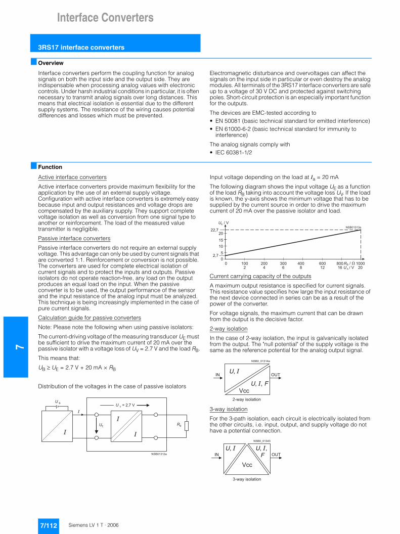
7Interface Converters
3RS17 interface converters
■ Overview
Interface converters perform the coupling function for analog signals on both the input side and the output side. They are indispensable when processing analog values with electronic controls. Under harsh industrial conditions in particular, it is often necessary to transmit analog signals over long distances. This means that electrical isolation is essential due to the different supply systems. The resistance of the wiring causes potential differences and losses which must be prevented.
Electromagnetic disturbance and overvoltages can affect the signals on the input side in particular or even destroy the analog modules. All terminals of the 3RS17 interface converters are safe up to a voltage of 30 V DC and protected against switching poles. Short-circuit protection is an especially important function for the outputs.
The devices are EMC-tested according to• EN 50081 (basic technical standard for emitted interference)• EN 61000-6-2 (basic technical standard for immunity to
interference)
The analog signals comply with• IEC 60381-1/2
■ Function
Active interface converters
Active interface converters provide maximum flexibility for the application by the use of an external supply voltage. Configuration with active interface converters is extremely easy because input and output resistances and voltage drops are compensated by the auxiliary supply. They support complete voltage isolation as well as conversion from one signal type to another or reinforcement. The load of the measured value transmitter is negligible.
Passive interface converters
Passive interface converters do not require an external supply voltage. This advantage can only be used by current signals that are converted 1:1. Reinforcement or conversion is not possible. The converters are used for complete electrical isolation of current signals and to protect the inputs and outputs. Passive isolators do not operate reaction-free, any load on the output produces an equal load on the input. When the passive converter is to be used, the output performance of the sensor and the input resistance of the analog input must be analyzed. This technique is being increasingly implemented in the case of pure current signals.
Calculation guide for passive converters
Note: Please note the following when using passive isolators:
The current-driving voltage of the measuring transducer UE must be sufficient to drive the maximum current of 20 mA over the passive isolator with a voltage loss of UV = 2.7 V and the load RB.
This means that:
UB � UE = 2.7 V + 20 mA × RB
Distribution of the voltages in the case of passive isolators
Input voltage depending on the load at Ia = 20 mA
The following diagram shows the input voltage UE as a function of the load RB taking into account the voltage loss UV. If the load is known, the y-axis shows the minimum voltage that has to be supplied by the current source in order to drive the maximum current of 20 mA over the passive isolator and load.
Current carrying capacity of the outputs
A maximum output resistance is specified for current signals. This resistance value specifies how large the input resistance of the next device connected in series can be as a result of the power of the converter.
For voltage signals, the maximum current that can be drawn from the output is the decisive factor.
2-way isolation
In the case of 2-way isolation, the input is galvanically isolated from the output. The "null potential" of the supply voltage is the same as the reference potential for the analog output signal.
3-way isolation
For the 3-path isolation, each circuit is electrically isolated from the other circuits, i.e. input, output, and supply voltage do not have a potential connection.
� � �
� �
�
�
� � � � � � � � � �
� �
�
�
� � � � � � �
�
� � �
� �
� � � � � � � �
� � � � �� � � � �� � � �
� ��
� � ��
� � ��
� � ��
� � �� �
� � � � �
� � � � � �
�
� � �
� � � � �
� � �
� � � � � � �
� � � � � � � � � � � � � � �
� � � � �
� � �
� � � � �
� � � � � � � � � � � � � �
7/112 Siemens LV 1 T · 2006

Interface Converters
7
3RS17 interface converters
7/113Siemens LV 1 T · 2006
■ Technical specifications
1) For 3RS17 06: 0.1 % for selected output 4 ... 20 mA; 0.3 % for selected output 0 ... 20 mA; 0.3 % for selected output 0 ... 10 V and from an input
voltage > 50 mV. For an input voltage < 50 mV, an offset of max. 20 ms is effective at the output.
Type 3RS17 24 V AC/DC 24 ... 240 V AC/DCGeneral dataSupply voltage operating range DC 0.7 ... 1.25 x Un 0.7 ... 1.1 x Un
AC 0.8 ... 1.2 x Un 0.8 ... 1.1 x Un
Rated power W Typical 0.3 Typical 0.75
Electrical isolation of input/output Active disconnector: 1500 V, 50 Hz, 1 min; Passive disconnector: 500 V, 50 Hz, 1 min
4000 V, 50 Hz, 1 min
Rated insulation voltage Ui pollution degree 2 Overvoltage category III acc. to DIN VDE 0100
V 50 300
Ambient temperature During operation °C -25 ... +60During storage °C -40 ... +85
Conductor cross-sections Screw terminals• Conductor cross-section
- Solid mm2 1 x (0.25 ... 4)- Finely stranded with or without end sleeve mm2 1 x (0.5 ... 2.5)
• Terminal screw M3
Spring-loaded terminal• Solid or finely stranded mm2 1 x (0.08 ... 2.5)• Finely stranded with end sleeve mm2 1 x (0.25 ... 1.5)
Degree of protection Enclosures IEC 529 IP30Terminals IEC 529 IP20
Permissible mounting position Any
Mounting onto standard rail EN 50022 mm 35
Vibration resistance IEC 68-2-6 Hz/mm 10-55/0.35
Shock resistance IEC 68-2-27 g/ms 15/11InputImpedance Voltage inputs k� 330
Current inputs, active � 100
Input voltage max. Voltage inputs V 30 AC/DC Current inputs, active V 30 AC/DC
Response current Current inputs, passive µA 100/250 (6.2 mm width)
Voltage drop Current inputs, passive V 2.7 at 20 mAOutputImpedance Voltage output, 0 ... 10 V � 55
Output load Current 0/4 ... 20 mA active, max. � 400Current 0 ... 20 mA passive, max. � 1000 at 20 mA, 400 at 20 mA (6.2 mm width)Frequency, min. � 2.400
Output voltage Frequency V 20.9
Output current Voltage output 0 ... 10 V, max. mA 21for supply voltage Frequency, max. mA 10
Short-circuit current Voltage output, 0 ... 10 V mA 40Current output, 0 ... 20 mA, passive mA Corresponds to the input currentFrequency mA 15
Protection of the outputs Short-circuit resistant
Max. overvoltage at output V 30AccuracyTotal error at 23 °C Active disconnector (frequency) % 0.1
Active disconnector (U, I) % 0.11)
Linearity error Active disconnector (U, I) % 0.02Active disconnector (frequency) % 0.02
Deviation due to ambient temperature
Active disconnector (frequency) 0 ... 50 Hz: 7.5 mHz/K; 0 ... 100 Hz: 15 mHz/K; 0 ... 1 kHz: 0.15 Hz/K;0 ... 10 kHz: 1.5 Hz/K
Active disconnector (U, I) 0 ... 10 V: 1.5 mV/K; 0/4 ... 20 mA: 3 µA/KPassive disconnector Width 6.2 mm: 100 ppm/K of measured value
Width 12.5 mm: with load < 600 �: < 50 ppm/K of measured value;with load � 600 �: < 175 ppm/K of measured value
Transmission error Passive disconnector % 0.1
Measured value load error %/� 0.06/100
Limit frequency at 3 dB Active disconnector (frequency) Hz 30Active disconnector (U, I) Hz 30Passive disconnector Hz 50
Rise time (10 to 90 %) Active disconnector (frequency) 10 + 1 periodActive disconnector (U, I) ms 10
Settling time at 1 % accuracy
Active disconnector (frequency) 30 + 1 periodActive disconnector (U, I) ms 30
Residual ripple Active disconnector (U, I) mVeff < 5 Passive disconnector mVeff < 8
The accuracy refers to the measurement range end value if not otherwise stated.

7Interface Converters
3RS17 interface converters
■ Dimensional drawings
1) Width for 3RS17 25 is approx. 90 mm.
2) Dimensions for screw-type connection.
3) Dimensions for spring-loaded terminal.
■ Schematics
6.2 mm design 12.5 mm design 17.5 mm design
���
��
��
��
�
��
��
��
��
��
��
��
�
�
��
�� �
�
�� �
�
�� �
3RS17 00-..D.. 3RS17 02-..D.. 3RS17 03-..D.. 3RS17 05-..D.. 3RS17 06- .FD00
3RS17 06-.FE00 3RS17 0.-..W00
3RS17 25-.FD00 3RS17 25-.FW00
3RS17 20-.ET00 3RS17 21-.ET00
3RS17 22-.ET00
�� �
�� �� �
��� ���
������
���
�
� �
�
�
����� � �����
��� ���
�������
����
�
� �
�� �
�� �
� ����
�� � ������ �
��� ����
�������
��� �
�
����
�� � �� �
� ����
�� � �����
��� ����
�������
��� �
�
����
�� �
� �
������ � �����
�� �� �
��� ���
�������
��� �
�
� �
�� �
�� �
� ����
�� � ������ �
��� ����
������
��� �
�
����
�� � �� �
� ����
������ � �����
�
�
��������
���
���
�����
�����
�
�
��� ����
�������
��� �
�
�����
�
�
��
�������
���
���
���
���
�����
�����
�����
�����
��
��
������
��
7
7/114 Siemens LV 1 T · 2006