monarch 19 series - siasa.com de panico 19-series.pdf · how to order sequence example door device...
TRANSCRIPT
2Questions? Call: 800-826-5792 / FAX: 800-924-3551 / email: [email protected] / www.monarchhardware.com
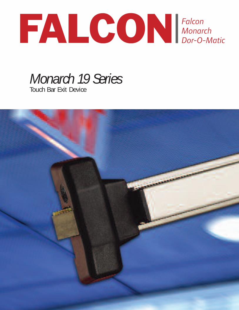
Monarch 19 SeriesTouch Bar Exit Device
Ingersoll Rand’s Security Technologies Sector is a leading global provider of products and services that make environments safe,
secure and productive. The Sector’s market-leading products include electronic and biometric access control systems; time and
attendance and personnel scheduling systems; mechanical locks and portable security, door closers and exit devices, steel doors
and frames, architectural hardware and technologies and services for global security markets.
www.falcon.ingersollrand.com
© 2007 Ingersoll Rand Company FA-5233 REV 12/07

T H E F A L C O N D I F F E R E N C E M O N A R C H 1 9 S E R I E S
S A F E T Y , S E C U R I T Y A N D U N C O M P R O M I S I N G V A L U E
32
F E A T U R E S
At Falcon, we know that every product you sell not only has to meet local building codes, but also
your expectations for performance and quality. We take your expectations seriously, and that’s why
we build our door hardware to deliver durability, convenience and unmatched value. After all, we’ve
built our reputation on the same standards that you have – providing quality products at a
reasonable price delivered on time. It’s the way we do business and it’s what makes Falcon door
hardware a powerful choice no matter what your project.
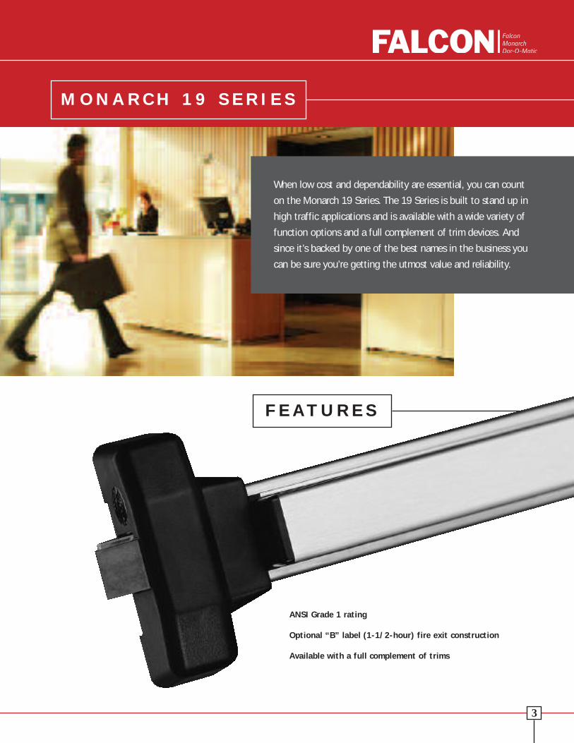
When low cost and dependability are essential, you can count
on the Monarch 19 Series. The 19 Series is built to stand up in
high traffic applications and is available with a wide variety of
function options and a full complement of trim devices. And
since it’s backed by one of the best names in the business you
can be sure you’re getting the utmost value and reliability.
ANSI Grade 1 rating
Optional “B” label (1-1/2-hour) fire exit construction
Available with a full complement of trims
T H E F A L C O N D I F F E R E N C E M O N A R C H 1 9 S E R I E S
S A F E T Y , S E C U R I T Y A N D U N C O M P R O M I S I N G V A L U E
32
F E A T U R E S
At Falcon, we know that every product you sell not only has to meet local building codes, but also
your expectations for performance and quality. We take your expectations seriously, and that’s why
we build our door hardware to deliver durability, convenience and unmatched value. After all, we’ve
built our reputation on the same standards that you have – providing quality products at a
reasonable price delivered on time. It’s the way we do business and it’s what makes Falcon door
hardware a powerful choice no matter what your project.
When low cost and dependability are essential, you can count
on the Monarch 19 Series. The 19 Series is built to stand up in
high traffic applications and is available with a wide variety of
function options and a full complement of trim devices. And
since it’s backed by one of the best names in the business you
can be sure you’re getting the utmost value and reliability.
ANSI Grade 1 rating
Optional “B” label (1-1/2-hour) fire exit construction
Available with a full complement of trims

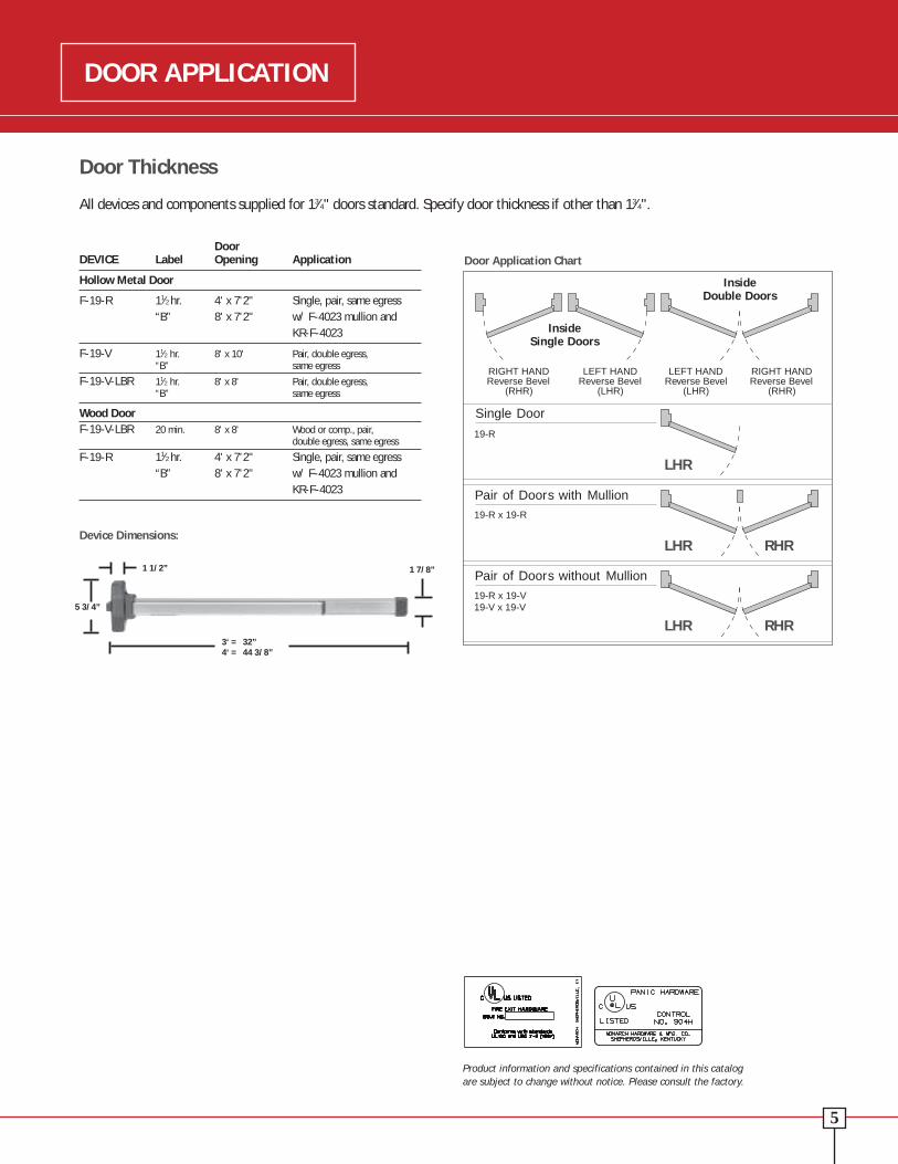
How to Order Sequence Example
DoorDEVICE Label Opening Application
Hollow Metal Door
F-19-R 11⁄2 hr. 4' x 7'2" Single, pair, same egress “B” 8' x 7'2" w/ F-4023 mullion and
KR-F-4023
F-19-V 11⁄2 hr. 8' x 10' Pair, double egress, “B” same egress
F-19-V-LBR 11⁄2 hr. 8' x 8' Pair, double egress, “B” same egress
Wood DoorF-19-V-LBR 20 min. 8' x 8' Wood or comp., pair,
double egress, same egress
F-19-R 11⁄2 hr. 4' x 7'2" Single, pair, same egress “B” 8' x 7'2" w/ F-4023 mullion and
KR-F-4023
Door Thickness
All devices and components supplied for 13⁄4" doors standard. Specify door thickness if other than 13⁄4".
INSIDE INSIDE
Single Door
Pair of Doors with Mullion
Pair of Doors without Mullion
19-R
19-R x 19-R
19-R x 19-V19-V x 19-V
RIGHT HANDReverse Bevel
(RHR)
LEFT HANDReverse Bevel
(LHR)
LEFT HANDReverse Bevel
(LHR)
RIGHT HANDReverse Bevel
(RHR)
InsideDouble Doors
InsideSingle Doors
LHR
LHR RHR
LHR RHR
Product information and specifications contained in this catalog are subject to change without notice. Please consult the factory.
Door Application Chart
DOOR APPLICATIONADDITIONAL INFORMATION
F 19 V L-DANE US32D 3' LHR LBR SNB WDPrefixes
CD Cylinder DoggingAE Touchbar Request to ExitDM Latchbolt and Device Monitor SwitchKOR Key Bypass SwitchLK Locking Trim Monitor SwitchLM Latchbolt Status SwitchED Electric Dogging
RatingF Fire Exit HardwareBlank Panic Exit Hardware
Device Series19 Touch Bar Device, Narrow Stile
Device TypeR RimV Surface Vertical Rod
Trim Function (see Trim pages for all functions)EO Exit Only K KnobDT Dummy Trim L Lever (Dane Standard)NL Night Latch TL Thumb LeverC Cylinder Trim Less Pull KIK Key in KnobTP Thumbpiece KIK Key in Lever
FinishUS32D SP28 SP313
Door Width 3' Standard Default 2' 9" Touchbar4' 2'5" 14" Touchbar_ Specify Exact Door Width 3'6" 20" Touchbar
HandingRHR Right Hand ReverseLHR Left Hand Reverse
Less Bottom RodLBR Less Bottom RodLBR-AFL LBR w/Auxiliary Fire Latch
Other Device OptionsEA Exit Alarm RBB Round Bottom Bolt SSTB Stainless Steel Touch BarHWEA Hard Wired Exit Alarm VRP Black Pad on Touch Bar TAC Tactile Warning
AccessoriesCYL Cylinder SNB Sex BoltsSK Shim Kit AMS All Machine Screws
Other Miscellaneous Door InformationHMD Hollow Metal Door SCDC Steel Channel Door Construction _ Door Label (20 min, 45 min, 90 min 1-1/2 hr)
HMF Hollow Metal Frame _ Specify other Door or Frame _ Stile WidthWD Wood Door Material information _ Frame Stop HeightWDF Wood Frame _ Door Height SGL Single DoorALD Aluminum Door _ Door Thickness PR Pair of Doors Swinging Same DirectionALF Aluminum Frame _ Door Undercut
1 1/2”
7 1/2”
3‘ = 34 5/8”4‘ = 46 5/8”
1 7/8”
2 1/2”
8 1/2”
3‘ = 33”4‘ = 45 3/8”
1 7/8”
1 1/2”
5 3/4”
3‘ = 32”4‘ = 44 3/8”
1 7/8”
2 1/2”
8 1/2”
40 13/16”(one size)
*Same as Active Head
Device Dimensions:
54

Panic Exit Hardware
The Monarch 19-R Series rim device that delivers superior panic hardware with modern touchbar styling. This non-handed device covers a 161 cutout and may be used on 13⁄4" narrow stile aluminum doors. The “EO” (Exit Only) device is ready to accept any trim function shown on page 12.
ANSI ANSIDEVICE & TRIM Type Function
19-R-EO 1 or 4 01
19-R-DT 1 or 4 02
19-R-NL 1 or 4 03
19-R-TP 1 or 4 05
19-R-TP-NL 1 or 4 06
19-R-K (or L or KIL) 1 or 4 08
19-R-K-NL (or L-NL or KIL-NL) 1 or 4 09
Note: For blank escutcheon specify BE.
SpecificationsHand: Non-Handed.
Functions: All functions built into “EO” device. All 19 Series trim works with rim or vertical devices. See Trim Selection Chart on pages 12 and 13.
Finishes: Powder-coated aluminum–SP28; powder-coated duranodic–SP313;stainless steel US-32D.
Strikes: F570 standard. 565, 571/571A, F490 optional.
Latchbolt: Stainless steel, 3⁄4" throw.
Deadlocking Latchbolt: Standard.
Dogging Feature: 1⁄2 turn hex dogging standard. No threaded parts to wear out.
Cylinder Dogging: Specify “CD” prefix. Use 11⁄8" long mortise cylinder with standard “A” cam.
Stock Sizes: 3'0" and 4'0". (See chart on page 15.)
Doors: 13⁄4" thick, wood or metal. Specify thickness if other than 13⁄4".
Narrow Stile Doors: Specify 565 strike. (See chart on page 15.)
Projection: 21⁄2" maximum; 17⁄8" dogged.
Electric Function: Can be interfaced with building security system. Security monitoring, electric dogging, exit indicator, and exit alarm available. (See separate electrical brochure.)
Fasteners: All mounting screws are concealed. Furnished with sheet metalscrews. Machine screws available, specify AMS.
Sex Bolts: 3-#4122 (1⁄4-20) SNB standard.
ANSI: Certified ANSI A156.3-2001 Grade 1 standards.
Shim Kit: For glass lite applications; 1⁄4" thick specify SK 19-R-1⁄4".
161 Cutout: Device covers 161 cutout with KIK/KIL and Centron trims. Other trim requires cover plate.
F570Standard
571/571AFor rim x verticalrod installations. 2789
Dogging Key
F490Strike optional
565For narrow stile door and
removable mullion installations. Cylinder Dogging
ZFire Exit Hardware
The F–19 RimZfire exit device is an excellent addition to the touchbar. This device is non-handed and is listed by UL for B label fire doorinstallations on 4'0" x 7'2" single doors and/or 8'0" x 7'2" double doors with an F–4023 removable mullion or KRF-4023. The “EO” (ExitOnly) device is ready to accept any trim function shown on page 12.
SpecificationsUL: “B” label (11⁄2 hr.); 4'0" x 7'2".
Functions: All functions built into “EO” device. All 19 Series trim works with rim or vertical devices. See Trim Selection Chart on pages 12 and 13.
Finishes: Powder-coated aluminum–SP28; powder-coated duranodic–SP313;stainless steel US-32D.
Strikes: Stainless steel, F570 or F490.
Latchbolt: Stainless steel, 3⁄4" throw.
Deadlocking Latchbolt: Standard.
Stock Sizes: 3'0" and 4'0". (See chart on page 15.)
Doors: 13⁄4" thick, wood or metal. Specify thickness if other than 13⁄4". (SNB must be specified on wood or composite doors.)
Projection: 21⁄2" maximum.
Electric Function: Can be interfaced with building security system. Security monitoring, electric dogging, exit indicator, and exit alarm available. (See separate electrical brochure.)
Fasteners: All mounting screws are concealed. Furnished with all machine screws.
Sex Bolts: When used with wood, composite or non-reinforced Hollow Metal, sex bolts must be specified, 3-#4122 (1⁄4-20) SNB standard.An additional 2-#2729 (10-24) SNB must be specified.
ANSI: Certified ANSI A156.3-2001 Grade 1 standards.
Shim Kit: For glass lite applications; 1⁄4" thick specify SK 19-R-1⁄4".
161 Cutout: Device covers 161 cutout with KIK/KIL and Centron trims. Other trim requires cover plate.
ANSI ANSIDEVICE & TRIM Type Function
F-19-R-EO 1 or 4 01
F-19-R-NL 1 or 4 03
F-19-R-TP 1 or 4 05
F-19-R-TP-NL 1 or 4 06
F-19-R-K (or L or KIL) 1 or 4 08
F-19-R-K-NL (or L-NL or KIL-NL) 1 or 4 09
Note: For blank escutcheon specify BE.
F570Standard
F490Strike optional
NON-HANDED RIM DEVICE F-19-R SERIESNON-HANDED RIM DEVICE 19-R SERIES
76

Latch retention hold is in thetop latch. Retainer is releasedwhen it engages the strike.
SpecificationsHand: Field reversible.
Functions: All functions built into “EO” device. All 19 Series trim works with rim or vertical devices. See Trim Selection Chart on pages 12 and 13.
Finishes: Powder-coated aluminum–SP28; powder-coated duranodic–SP313; stainless steel US-32D.
Strikes: 3788 strike is surface applied standard, 2130 strike is mortised into floor.
Angle Bracket: Use 4215 angle bracket in flush transom or rabbeted installations. Allows use of standard 3788 strike.
Latchbolt: Top stainless steel 3⁄4" throw. Bottom square bolt 1⁄2" throw.
Deadlocking Latchbolt: Standard.
Dogging Feature: 1⁄2 turn hex dogging standard. No threaded parts to wear out.
Cylinder Dogging: Specify “CD” prefix. Use 11⁄8" long mortise cylinder with standard “A” cam.
Stock Sizes: 3'0" and 4'0". (See chart on page 15.)
Doors: 13⁄4" thick, wood or metal. Specify thickness if other than 13⁄4".
Narrow Stile Doors: To 13⁄4" N.S. aluminum. With control trim–21⁄4" min. stile.
Projection: 21⁄2" max., 17⁄8" dogged.
Electric Function: Can be interfaced with building security systems. Securitymonitoring, electric dogging, exit indicator, and exit alarm available.
Fasteners: All mounting screws are concealed. Furnished with sheet metalscrews. Machine screws available, specify AMS.
Sex Bolts: 3–#4122 (1⁄4–20) SNB standard. Hollow core wood, light gaugeHollow Metal, etc. require additional sex bolts. 19–V: 6–#2729#10–24 SNB; 19–V–LBR: 3–#2729 #10–24 SNB
ANSI: Certified ANSI A156.3 2001 Grade 1 standards.
19–V: Latch retention and 3788 strike top, deadbolt and 2130 flush strike bottom.
19–V–LBR: 3788 strike top.
Vertical Rods: Furnished to length based on 405⁄16" horizontal CL from finished floor and a 7'0" door standard. Variations from these standards must be specified when ordering.
Shim Kit: For glass lites applications; 1⁄4" thick specify SK-19-V-1⁄4".
161 Cutout: Device covers 161 cutout with KIK/KIL and Centron trims. Other trim requires cover plate.
Cylinder Dogging2789Dogging Key
ANSI ANSIDEVICE & TRIM Type Function
19-V-EO 2 or 5 01
19-V-DT 2 or 5 02
19-V-NL 2 or 5 03
19-V-TP 2 or 5 05
19-V-TP-NL 2 or 5 06
19-V-K (or L) 2 or 5 08
19-V-K-NL (or KIL) 2 or 5 09
Note: For blank escutcheon specify BE.
Panic Exit Hardware
Manufactured to the same exacting standards as the 19 Rim, the 19–V Exit Device complies with most exit door requirements, and is fully reversible and surface applied. This device is regularly furnished with deadlocking top latch with latch retention and square bolt at bottom. The “EO” (Exit Only) device is ready to accept any trim function shown on page 12.
3788Strike
ZFire Exit Hardware
Manufactured to the same exacting standards as the F–19 Rim, the F–19–VZFire Exit Device complies with most exit door requirements, and is fully reversible and surface applied. This device is regularly furnished withdeadlocking top latch retention and square bolt at bottom. (This device is listed by UL for B label fire doorinstallations.) The “EO” (Exit Only) device is ready to accept any trim function shown on page 12.
SpecificationsHand: Field reversible.
Functions: All functions built into “EO” device. All 19 Series trim works with rim or vertical devices. See Trim Selection Chart on pages 12 and 13.
Finishes: Powder-coated aluminum–SP28; powder-coated duranodic–SP313;stainless steel US-32D.
Strikes: 3788 strike is surface applied. 2130 strike is mortised into floor.
Latchbolt: Top stainless steel 3⁄4" throw. Bottom square bolt 1⁄2" throw.
Deadlocking Latchbolt: Standard.
Stock Sizes: 3'0" and 4'0". (See chart on page 15.)
Doors: 13⁄4" thick, wood or metal. Specify if other than 13⁄4" thick.
Projection: 21⁄2" maximum.
Electric Function: Can be interfaced with building security systems. Security monitoring,electric dogging, exit indicator, and exit alarm available.
Fasteners: All mounting screws are concealed. All machine screws standard.
Sex Bolts: 3–#4122 (1⁄4–20) SNB standard. Composite or non-reinforced wood,Hollow Metal require additional sex bolts. F-19–V: 6–#2729 #10–24SNB; F-19–V–LBR: 3–#2729 #10–24 SNB
ANSI: Certified ANSI A156.3-2001 Grade 1 standards.
F-19-V: Latch retention and 3788 strike top deadbolt and 2130 flush strike bottom.
F-19-V-LBR: Latch retention and 3788 strike top.
Vertical Rods: Furnished to length based on a 405⁄16" horizontal CL from finished floor and a 7'0" door standard. Variations from these standards must be specified when ordering.
Shim Kit: For glass lites applications; 1⁄4" thick specify SK-19-V-1⁄4".
161 Cutout: Device covers 161 cutout with KIK/KIL and Centron trims. Other trim requires cover plate.
ANSI ANSIDEVICE & TRIM Type Function
F-19-V-EO 2 or 5 01
F-19-V-DT 2 or 5 02
F-19-V-NL 2 or 5 03
F-19-V-TP 2 or 5 05
F-19-V-TP-NL 2 or 5 06
F-19-V-K (or L or KIL) 2 or 5 08
F-19-V-K-NL (or L-NL or KIL-NL) 2 or 5 09
Note: For blank escutcheon specify BE.
3788Strike
Latch retention hold is in thetop latch. Retainer is releasedwhen it engages the strike. Thedoor is in the closed position.
2130Strike2130
Strike
REVERSIBLE VERTICAL ROD DEVICE 19-V SERIES REVERSIBLE VERTICAL ROD DEVICE F-19-V SERIES
98

Optional strike.
F490
• The 2923, (F)4023 and (F)KR4023 steel mullions are for use with the 19–R devices on doubledoor openings. Advantage: Increased security and tighter closure. Minimizes door warpage andsag. Regulates the flow of in-and-out traffic.
• Monarch removable mullions are easily removed and reinstalled for full width access.
• Rim devices are used on both leaves, attaining a perfectly symmetrical opening.
• The mullion assembly consists of a mullion, top and bottom mounting brackets and a screw pack.Soffit adapters are available for use with either the 2923 or the 4023 mullion. Please see PriceBook for ordering information.
• The (F)–4023 and KR(F)–4023 fire-rated mullion also includes four stabilizer blocks as required for labeled installations.
• Strikes are not furnished with the mullion. Please see page 11 for strike information.
• Mullions may be cut on the job for doors under stock lengths.
• KR mullions require 11⁄8" mortise cylinder with standard “A” cam.
Mullion Features
• Mullion fittings – ductile iron.
• (F)4023 and KR(F)4023 – 2" x 3" x height.
• 2923 mullion – 11⁄2" x 21⁄2" x height.
• Prime coat only.
• 7' or 8' door opening standard, other door opening as specified.
Cylinders
Control Trim
• Cylinders for control trim use 11⁄8" mortise cylinder with standard “A” cam (cam measuresapproximately 1" overall and 5⁄16" wide at tip), except NL Control which uses rim cylinder with either horizontal or vertical tailpiece.
• Cylinder supplied only when specified. (11⁄4" long and “C” keyway standard.)
• Cylinders available keyed alike and keyed different.
Centron Trim
• Rim cylinder.
Sex Bolts
Sex bolts are available for 13⁄4" door thickness. Screws to fit are available in 3⁄4" and 2" lengths to cover a wide range of door thicknesses. 2729 (#10-24 Thread) 4122 (1/4-20 Thread)
F-4023 Shown
Strikes
For (F) 19-R Rim Devices (center latching)
Adjustable surfacemounted for use withblade or applied stops.Mounts flush for 1/2"stop height.
Standard strike.
565F570
571/571A
Used on inactive leaf for device onactive leaf of pair of doors withoutremovable mullion. 571 keeps 25⁄16"backset. 571A is trimmer and projectsless into opening.
Extension rods are available in 12", 24"and 36" lengths in all finishes. Bothends tapped and all-thread included as connector.
Extension Rods
Angle bracket for 19-Vdevices flush transom applications. Does not require elimination of latchretention feature.
19-V optional bottom strike.
For (F) 19-V Surface Vertical Rod Devices
42152126A
19-V optionalbottom strike.
41552130
19-V bottom strike forgrouting into concreteor masonry floors.
Filler Plates
Removable Mullion
3788
Top strike for 19-V.
STRIKES AND ACCESSORIESACCESSORIES
Steel Filler Plates3721 Cylindrical Lock Front Filler3722 ASA Strike Filler - set no.
SC for 161 cutout3723 Mortise Lock Front Filler3722 ASA Strike Filler - set no.
SM for 86 cutout
3721/3722/3723
3721 3722
3723
8˝
21/4˝4 7/8˝
11/4˝
11/8˝ 11/4˝
1110
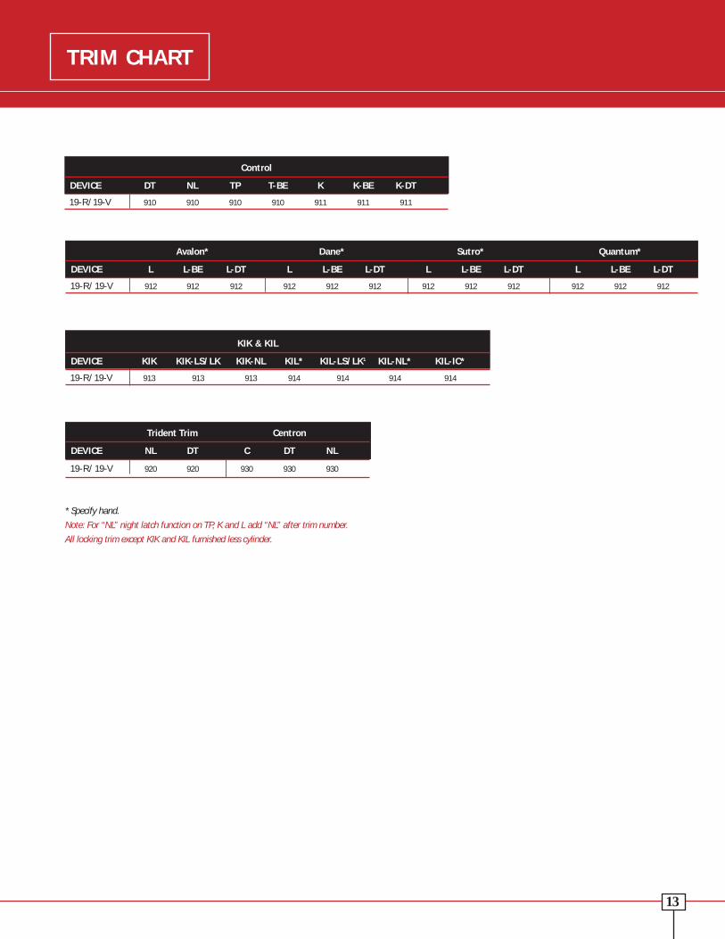
Avalon* Dane* Sutro* Quantum*
DEVICE L L-BE L-DT L L-BE L-DT L L-BE L-DT L L-BE L-DT
19-R/19-V 912 912 912 912 912 912 912 912 912 912 912 912
914KIL
Trim ChartTrim Designs
L-Control-Dane912LBEL-DTNL
L-Control-Sutro912LBEL-DTNL
Lever Projection: Quantum = 3"Sutro = 27⁄8 "Dane = 27⁄8 "
911K
BEK-DTNL
Control Trim
SP28, SP313 and US-32D.
Key locks or unlocks trim. Lever retractslatchbolt when trim is unlocked. Dane,Quantum and Sutro levers return towithin 1⁄2" of door.
Key locks or unlockstrim. Knob retractslatchbolt when trim is unlocked. Key locks or
unlocks trim.Thumbpieceretracts latchboltwhen trim isunlocked.
K-Control L-Control TP-Control DT-Control NL-Control
L-Control-Avalon912LBEL-DTNL
L-Control-Quantum912LBEL-DTNL 910TP
BENL
910DTPull when dogged.
910NLKey retractslatchbolt.
Cover Plates
Centron Trim
Key-In-Knob/Key-In-Lever
PULL ONLY 917 DT
CTC - 51⁄2" Round - 3⁄4"dia.Pull when dogged
4167
31⁄4" x 15" x .050Used with TP control & DT controlCovers 161 & 86 cutouts
4168
31⁄4" x 71⁄2" x .050Used with EO device to cover No. 86 cutout for mortise lock
4170
31⁄4" x 71⁄2" x .050Used with K control, DT/K control,L control, or DT/L controlCovers 161 & 86 cutouts
930 EO 930 C 930 DT 930 NL
Control
DEVICE DT NL TP T-BE K K-BE K-DT
19-R/19-V 910 910 910 910 911 911 911
*Specify hand.
Note: For “NL” night latch function on TP, K and L add “NL” after trim number.
All locking trim except KIK and KIL furnished less cylinder.
913
914-KIL-ICFor type 86 cutout specify 4174 inside cover plate.
KIK & KIL
DEVICE KIK KIK-LS/LK KIK-NL KIL* KIL-LS/LK1 KIL-NL* KIL-IC*
19-R/19-V 913 913 913 914 914 914 914
TRIM CHARTTRIM DESIGNS
Trident Trim Centron
DEVICE NL DT C DT NL
19-R/19-V 920 920 930 930 930
920 NL
Trident Trim
DT P
Trident
920 DT
DT P
Trident
1 3/4"4"
2 1/4"
5/8"
7 1/4"
1/2"1 3/4"
7 1/4"
4 5/8"
5/8"
2 1/4"
5/8"
2 1/4"
1 3/4"
11 3/4"
5/8"
2 1/4"
1 3/4"
11 3/4"
1312
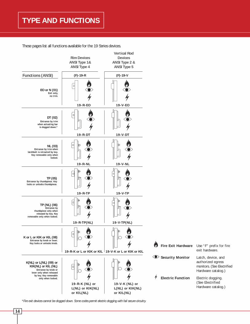
Z Fire Exit Hardware Use “F” prefix for fire exit hardware.
Security Monitor Latch, device, and authorized egress monitors. (See ElectrifiedHardware catalog.)
Electric Function Electric dogging. (See Electrified Hardware catalog.)
These pages list all functions available for the 19 Series devices.
Rim DevicesANSI Type 1&ANSI Type 4
Vertical Rod Devices
ANSI Type 2 &ANSI Type 5
Functions (ANSI) (F)-19-R (F)-19-V
19-R-EO 19-V-EO
19-R-DT 19-V-DT
19-R-NL 19-V-NL
Z
Z
Z
Z
Z
Z
Z Z
Z
Z
Z
ZEO or N (01)
Exit only, no trim.
DT (02) Entrance by trim
when actuating bar is dogged down.*
NL (03) Entrance by trim when
latchbolt is retracted by key.Key removable only when
locked.
TP (05) Entrance by thumbpiece. Keylocks or unlocks thumbpiece.
TP (NL) (06) Entrance by
thumbpiece only whenreleased by key. Key
removable only when locked.
K or L or KIK or KIL (08) Entrance by knob or lever. Key locks or unlocks knob.
K(NL) or L(NL) (09) orKIK(NL) or KIL (NL)
Entrance by knob or lever only when released
by key. Key removable only when locked.
19-R-TP 19-V-TP
19-R-TP(NL) 19-V-TP(NL)
19-R-K or L or KIK or KIL 19-V-K or L or KIK or KIL
19-R-K (NL) or 19-V-K (NL) orL(NL) or KIK(NL) L(NL) or KIK(NL)or KIL(NL) or KIL(NL)
*Fire exit devices cannot be dogged down. Some codes permit electric dogging with fail secure circuitry.
Double Doors
DEVICE Top Bottom Min. Door& TRIM Length Strike Strike Stile Opening Width
(F) 19-V 3'0" 3788 2130 31⁄2" 2'51⁄4" TO 3'0"
(F) 19-V 4'0" 3788 2130 31⁄2" 3'0" TO 4'0"
Note: For (F-) 19-V-LBR use “V” information less bottom strike.
F-19-V-LBR requires use of auxilary fire latch.
Single Doors with 5⁄8" Stop
DEVICE Min. Door& TRIM Length Strike Stile Opening Width
19-R 3'0" F570 31⁄2" 2'51⁄4" TO 3'0"
565 13⁄4"* 2'43⁄4" TO 2'91⁄4"
F-19-R 3'0" F570 31⁄2" 2'51⁄4" TO 3'0"
19-R 4'0" F570 31⁄4" 3'0" TO 4'0"
565 13⁄4"* 3'0" TO 3'93⁄4"
F-19-R 4'0" F570 31⁄4" 3'0" TO 4'0"
*For EO, O with pull and NL functions only. 2-1/4" minimum stile required for control trim.
Dimensions:
• Recommended height from finished floor – 405⁄16" at CL.
• Touchbar Projections: Neutral - 21⁄2", Depressed – 17⁄8"
• Extension rods or longer top rods available upon request.Specify door height.
• Dummy touchbar available. Specify 190 DT 3’ or 4’.Overall length: 3’: 301⁄2" 4’: 425⁄8"
• Changes for minimum door size for charts on left: For cylinder dogging, add 21⁄4" to minimum door size. Forexit alarm, add 41⁄2" to minimum door size. For electricdogging, add 41⁄2" to minimum door size.
• To fit on smaller door consult factory.
Double Doors with Mullion
DEVICE Min. Door Mullion& TRIM Length Strike Stile Opening Width Fire Panic
19-R 3'0" F570 31⁄2" 2'51⁄4" TO 3'0" – 29231
33⁄4" – 4023/KR4023
565 31⁄8" 2'43⁄4" TO 2'91⁄4" – 29231
33⁄8" – 4023/KR4023
F-19-R 3'0" F-570 33⁄4" 2'51⁄4" TO 3'0" (F)4023 –
KR(F)4023 –
19-R 4'0" F570 31⁄2" 3'0" TO 4'0" – 29231
33⁄4" – 4023/KR4023
565 31⁄8" 3'0" TO 3'93⁄4" – 29231
33⁄8" – 4023/KR4023
F-19-R 4'0" F-570 33⁄4" 3'0" TO 4'0" (F)4023 –
KR(F)4023 –
1 To cover 161 cutout on double door installation, specify 2923 mullion with 565 strike.
TYPE AND FUNCTIONSTYPE AND FUNCTIONS
Z
Z
1514

2Questions? Call: 800-826-5792 / FAX: 800-924-3551 / email: [email protected] / www.monarchhardware.com
Monarch 19 SeriesTouch Bar Exit Device
Ingersoll Rand’s Security Technologies Sector is a leading global provider of products and services that make environments safe,
secure and productive. The Sector’s market-leading products include electronic and biometric access control systems; time and
attendance and personnel scheduling systems; mechanical locks and portable security, door closers and exit devices, steel doors
and frames, architectural hardware and technologies and services for global security markets.
www.falcon.ingersollrand.com
© 2007 Ingersoll Rand Company FA-5233 REV 12/07