molten slags formed during gasification of carbon
TRANSCRIPT
MOLTEN SLAGS FORMED DURING GASIFICATION OF CARBON FEEDSTOCK AND THEIR INTERACTION WITH HIGH CHROME OXIDE REFRACTORY LINERS OF AIR COOLED SLAGGING GASIFIERS
James Bennett & Cynthia PowellNational Energy Technology Laboratory - USDOE, USA
ABSTRACTGasifiers are used to produce CO and H2 (called synthesis gas or syngas) from different
carbon feedstock. Syngas is used in chemical production and power generation, with
research emphasis on applications such as liquid fuel synthesis. The term gasification
describes the high temperature, high pressure process that occurs in an oxygen deficient
environment, producing syngas by the following simplified reaction: C + H2O + O2
(shortage) → H2 + CO + CO2 + H2S + minority gases + excess carbon as char + ash (from
mineral impurities in the carbon source). Primary carbon sources used in gasification
include coal, petcoke, natural gas, biomass, or combinations of these.
The air cooled slagging gasifier (the focus of this paper) typically operates between
1325 and 1575ºC, and at pressures between 400 and 1000 psi - conditions that depend
on the specific gasifier design and the carbon feedstock. Because of the temperature and
pressure involved in gasification, it occurs in a steel vessel lined with pre-fired refractory
shapes. The major components of the refractory liner are chrome oxide (60-95 pct),
alumina (2-40 pct), and/or zirconia (0-12 pt). Service life of the refractory varies between
3 and 24 months; and is dependent on slag chemistry, temperature of operation, material
throughput, and gasifier cycling frequency. Two primary causes of refractory failure have
been determined through post-mortem analyses of material removed from commercial
gasifiers: slag corrosion/dissolution of the refractory liner and spalling caused by slag
penetration of the refractory material. The slag causing refractory failure originates from
impurities in the carbon feedstock that liquefy at the elevated temperature of gasification;
and are typically high in oxides of Si, Fe, Al, and Ca. Other elements that may be present
in the slag at elevated levels include S, K, Na, Mg, Ni and V; with the quantities of each
element depending on the carbon feedstock source. The origin of the molten slag and how
it interacts with the refractory liner to cause wear will be discussed in this paper.
1324
CHAPTER 09
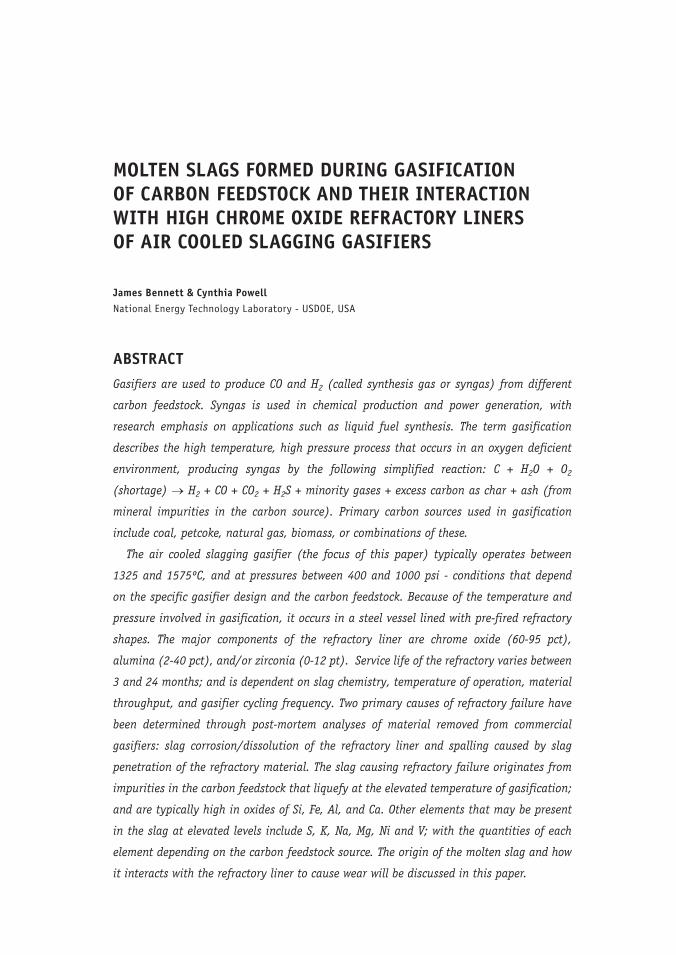
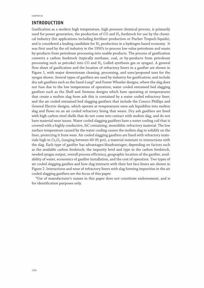
INTRODUCTIONGasification as a modern high temperature, high pressure chemical process, is primarily used for power generation, the production of CO and H2 feedstock for use by the chemi-cal industry (for applications including fertilizer production or Fischer Tropsch liquids), and is considered a leading candidate for H2 production in a hydrogen based economy. It was first used by the oil industry in the 1950’s to process low value petroleum and waste by-products from petroleum processing into usable products. The process of gasification converts a carbon feedstock (typically methane, coal, or by-products from petroleum processing such as petcoke) into CO and H2 (called synthesis gas or syngas). A general flow sheet of gasification and the location of refractory liners in a gasifier are shown in Figure 1, with major downstream cleaning, processing, and uses/proposed uses for the syngas shown. Several types of gasifiers are used by industry for gasification; and include dry ash gasifiers such as the Sasol-Lurgi* and Foster Wheeler designs, where the slag does not fuse due to the low temperature of operation; water cooled entrained bed slagging gasifiers such as the Shell and Siemens designs which have operating at temperatures that create a molten slag from ash this is contained by a water cooled refractory liner; and the air cooled entrained bed slagging gasifiers that include the Conoco Phillips and General Electric designs, which operate at temperatures were ash liquidifies into molten slag and flows on an air cooled refractory lining that wears. Dry ash gasifiers are lined with high carbon steel shells that do not come into contact with molten slag, and do not have material wear issues. Water cooled slagging gasifiers have a water cooling coil that is covered with a highly conductive, SiC containing, monolithic refractory material. The low surface temperature caused by the water cooling causes the molten slag to solidify on the liner, protecting it from wear. Air cooled slagging gasifiers are lined with refractory mate-rials high in Cr2O3 (ranging between 60-95 pct), a material resistant to interactions with the slag. Each type of gasifier has advantages/disadvantages; depending on factors such as the available carbon feedstock; the impurity level and type in the carbon feedstock, needed syngas output, overall process efficiency, geographic location of the gasifier, avail-ability of water, economics of gasifier installation, and the cost of operation. Two types of air cooled slagging gasifies and how slag interacts with their hot face liners are shown in Figure 2. Interactions and wear of refractory liners with slag forming impurities in the air cooled slagging gasifiers are the focus of this paper.
*Use of manufacturer’s names in this paper does not constitute endorsement, and is for identification purposes only.
1325MOLTEN 2009. Santiago, Chile
Molten Slags Formed during Gasification of Carbon Feedstock...
Figure 1: General gasification facility and possible applications for the syngas product
a) b) c)
Figure 2: Two types of air cooled slagging gasifier used for syngas production, and how slag flows and interacts with their hot face refractory liners. a) GE design. b) Conoco Philips design. c) Cross section of a gasification chamber showing the as installed lining (initial installation) and section after usage (during gasification) and slag attack
In practice, a gasifier is nothing more than a high temperature, high pressure reaction vessel used to contain reactions between a carbon feedstock, oxygen, and water (steam). The gasification process typically occurs between 2.76 and 6.89 MPa, in a shortage of oxygen necessary for theoretical combustion (a reducing environment with an oxygen partial pressure between 10-7 and 10-9). Gasification occurs at temperatures between 1325º and 1575ºC. The temperature of gasification is high enough that impurities in the carbon feedstock liquefy, flowing down the gasifier sidewalls, and is a major factor in de-termining gasification temperature. The general gasification reaction, regardless of the carbon feedstock, is as listed below:
C + H2O (gas) + O2 → CO + H2 + CO2 + minority gases + by-products
Note: By-products include mineral impurities in the carbon feedstock that become ash or slag

1326
CHAPTER 09
Air cooled slagging gasifiers are lined with high chrome oxide refractory material of the two types listed in Table 1 (chromia/alumina and chromia/alumina/zirconia), which contains the severe service gasification environment. These liners must withstand hot corrosive gases, slags from impurities within the carbon feedstock that liquefy into slag at the elevated processing temperatures, thermal cycling of the gasifier, a reducing/oxi-dizing environment of gasification, and contact with carbon and gases like H2 and CO. The high chrome oxide refractories currently used to line the hot face of air cooled slag-ging gasifiers have their origins traceable to research work conducted in the mid 70’s to mid 80’s, research that was conducted and/or sponsored by DOE, EPRI, the refractory industry, and gasifier users [1, 2, 3]. Although the high chrome oxide refractory identified from that research is a superior liner material to others that were evaluated, it does not meet the service life requirements of the gasification industry, failing between 3 and 24 months, after which the gasifier is taken out of service for between 4 and 21 days while a new lining is installed or repairs to the existing lining are made. Gasifier operators would like a refractory repair schedule that matches other long term maintenance required in the gasification operation.
Gasifier ash or slag originating from the carbon feedstock is the primary cause of re-fractory failure. Of the major feedstock, ash content can range from close to 0 pct for natural gas to a high of 10 pct or more for coal, with petcoke being low - about a percent or less. Distinct differences exist in the different gasifier designs, the temperature of op-eration, and the liner materials used to contain the gasification reaction; causing differ-ent refractory wear patterns and mechanisms within the gasifiers. Because of the high ash content in gasifiers using coal, petcoke, or combinations of them and because of their corrosive nature; gasifiers using these sources of carbon feedstock require high chrome oxide refractories of the types shown in Table 1. In contrast, gasifiers that use natural gas (which has essentially no ash) are lined with high alumina refractories. Depending on location in the gasifier, chrome oxide content in the gasifier can vary between 60 and 95 wt pct, with the highest levels being used in the high wear areas.
Table 1: Chemical composition and physical properties of commonly used high chrome oxide refractories used in air cooled slagging gasifiers
Chemistry (wt pct) Brick Type
A B
Cr2O3 90.3 87.3
Al2O3 7.0 2.5
ZrO2 0.01 5.2
Bulk Density (gms/cc) 4.21 4.07
Porosity (pct) 16.7 16.5
Cold Crushing Strength (MPa) 48.3 66.9
*Data from manufacturer’s technical data sheet
Regardless of the carbon source, carbon feedstock enters the gasifier as particles about 100 microns or less in size through high pressure, proprietary injectors, along with water and oxygen. The air cooled slagging gasifier designs shown in Figure 2a and b can proc-ess over 1400 tons/day of a carbon feedstock, producing up to 100 tons or more per day of ash from impurities in the carbon source. The ash liquefies at the high gasification temperature, exiting the gasifier at its base as a molten slag, where it is water quenched or cooled in the radiant syngas cooler. The molten slag produced by the ash is a corrosive liquid that interacts with the refractory lining; producing new mineral phases, causing chemical dissolution of the refractory liner, and penetrates the porous refractory lining; all contributing to lining wear and premature failure.
1327MOLTEN 2009. Santiago, Chile
Molten Slags Formed during Gasification of Carbon Feedstock...
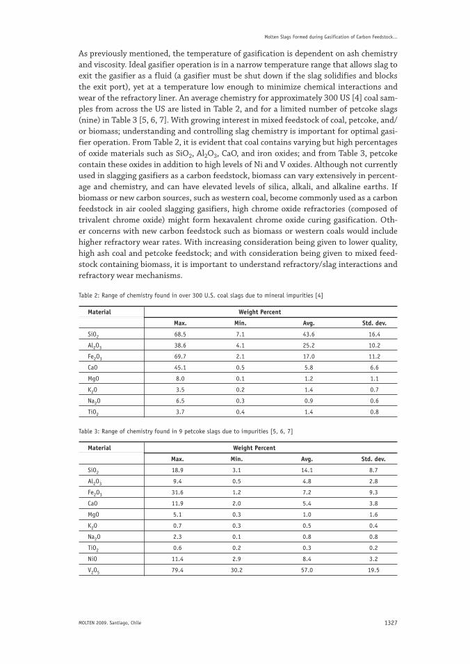
As previously mentioned, the temperature of gasification is dependent on ash chemistry and viscosity. Ideal gasifier operation is in a narrow temperature range that allows slag to exit the gasifier as a fluid (a gasifier must be shut down if the slag solidifies and blocks the exit port), yet at a temperature low enough to minimize chemical interactions and wear of the refractory liner. An average chemistry for approximately 300 US [4] coal sam-ples from across the US are listed in Table 2, and for a limited number of petcoke slags (nine) in Table 3 [5, 6, 7]. With growing interest in mixed feedstock of coal, petcoke, and/or biomass; understanding and controlling slag chemistry is important for optimal gasi-fier operation. From Table 2, it is evident that coal contains varying but high percentages of oxide materials such as SiO2, Al2O3, CaO, and iron oxides; and from Table 3, petcoke contain these oxides in addition to high levels of Ni and V oxides. Although not currently used in slagging gasifiers as a carbon feedstock, biomass can vary extensively in percent-age and chemistry, and can have elevated levels of silica, alkali, and alkaline earths. If biomass or new carbon sources, such as western coal, become commonly used as a carbon feedstock in air cooled slagging gasifiers, high chrome oxide refractories (composed of trivalent chrome oxide) might form hexavalent chrome oxide curing gasification. Oth-er concerns with new carbon feedstock such as biomass or western coals would include higher refractory wear rates. With increasing consideration being given to lower quality, high ash coal and petcoke feedstock; and with consideration being given to mixed feed-stock containing biomass, it is important to understand refractory/slag interactions and refractory wear mechanisms.
Table 2: Range of chemistry found in over 300 U.S. coal slags due to mineral impurities [4]
Material Weight Percent
Max. Min. Avg. Std. dev.
SiO2 68.5 7.1 43.6 16.4
Al2O3 38.6 4.1 25.2 10.2
Fe2O3 69.7 2.1 17.0 11.2
CaO 45.1 0.5 5.8 6.6
MgO 8.0 0.1 1.2 1.1
K2O 3.5 0.2 1.4 0.7
Na2O 6.5 0.3 0.9 0.6
TiO2 3.7 0.4 1.4 0.8
Table 3: Range of chemistry found in 9 petcoke slags due to impurities [5, 6, 7]
Material Weight Percent
Max. Min. Avg. Std. dev.
SiO2 18.9 3.1 14.1 8.7
Al2O3 9.4 0.5 4.8 2.8
Fe2O3 31.6 1.2 7.2 9.3
CaO 11.9 2.0 5.4 3.8
MgO 5.1 0.3 1.0 1.6
K2O 0.7 0.3 0.5 0.4
Na2O 2.3 0.1 0.8 0.8
TiO2 0.6 0.2 0.3 0.2
NiO 11.4 2.9 8.4 3.2
V2O5 79.4 30.2 57.0 19.5
1328
CHAPTER 09
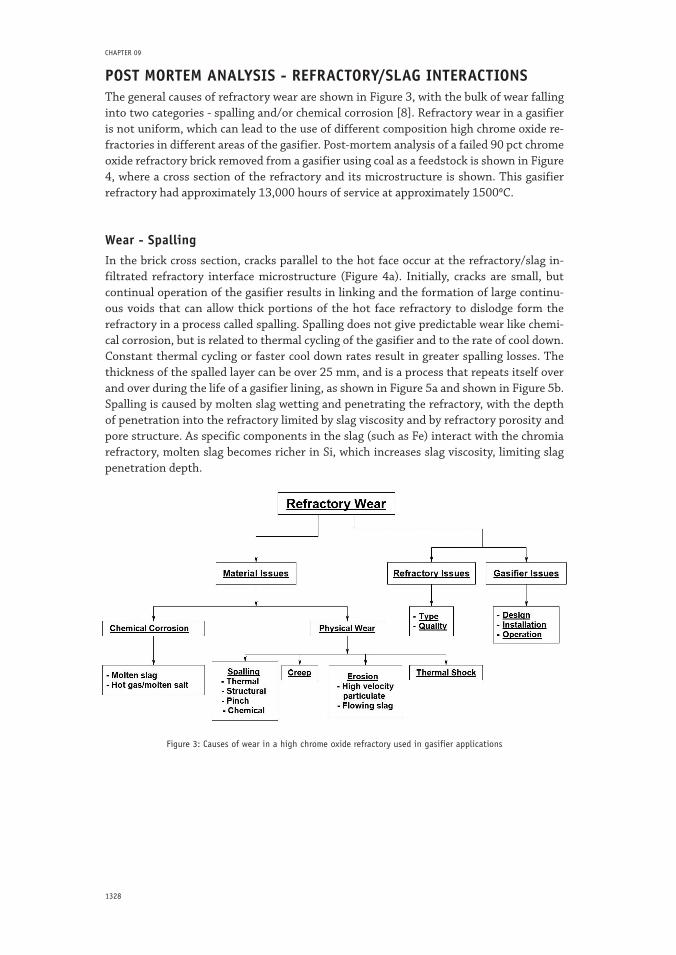
POST MORTEM ANALYSIS - REFRACTORY/SLAG INTERACTIONS The general causes of refractory wear are shown in Figure 3, with the bulk of wear falling into two categories - spalling and/or chemical corrosion [8]. Refractory wear in a gasifier is not uniform, which can lead to the use of different composition high chrome oxide re-fractories in different areas of the gasifier. Post-mortem analysis of a failed 90 pct chrome oxide refractory brick removed from a gasifier using coal as a feedstock is shown in Figure 4, where a cross section of the refractory and its microstructure is shown. This gasifier refractory had approximately 13,000 hours of service at approximately 15000C.
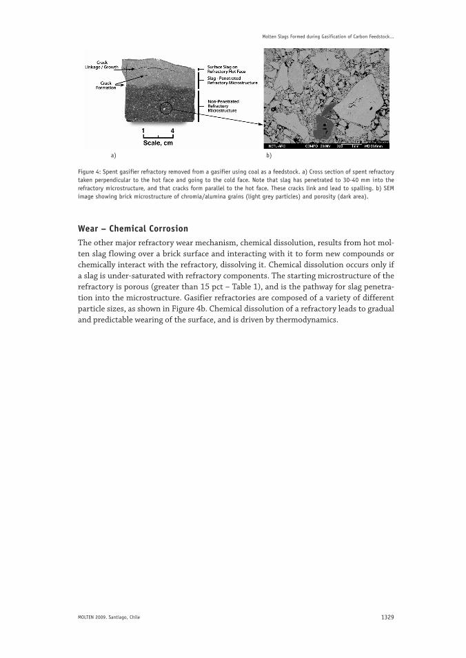
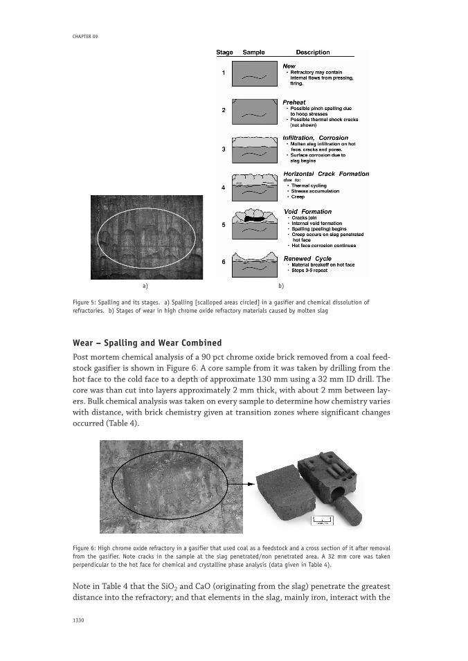
Wear - SpallingIn the brick cross section, cracks parallel to the hot face occur at the refractory/slag in-filtrated refractory interface microstructure (Figure 4a). Initially, cracks are small, but continual operation of the gasifier results in linking and the formation of large continu-ous voids that can allow thick portions of the hot face refractory to dislodge form the refractory in a process called spalling. Spalling does not give predictable wear like chemi-cal corrosion, but is related to thermal cycling of the gasifier and to the rate of cool down. Constant thermal cycling or faster cool down rates result in greater spalling losses. The thickness of the spalled layer can be over 25 mm, and is a process that repeats itself over and over during the life of a gasifier lining, as shown in Figure 5a and shown in Figure 5b. Spalling is caused by molten slag wetting and penetrating the refractory, with the depth of penetration into the refractory limited by slag viscosity and by refractory porosity and pore structure. As specific components in the slag (such as Fe) interact with the chromia refractory, molten slag becomes richer in Si, which increases slag viscosity, limiting slag penetration depth.
Figure 3: Causes of wear in a high chrome oxide refractory used in gasifier applications
1329MOLTEN 2009. Santiago, Chile
Molten Slags Formed during Gasification of Carbon Feedstock...
a) b)
Figure 4: Spent gasifier refractory removed from a gasifier using coal as a feedstock. a) Cross section of spent refractory taken perpendicular to the hot face and going to the cold face. Note that slag has penetrated to 30-40 mm into the refractory microstructure, and that cracks form parallel to the hot face. These cracks link and lead to spalling. b) SEM image showing brick microstructure of chromia/alumina grains (light grey particles) and porosity (dark area).
Wear – Chemical CorrosionThe other major refractory wear mechanism, chemical dissolution, results from hot mol-ten slag flowing over a brick surface and interacting with it to form new compounds or chemically interact with the refractory, dissolving it. Chemical dissolution occurs only if a slag is under-saturated with refractory components. The starting microstructure of the refractory is porous (greater than 15 pct – Table 1), and is the pathway for slag penetra-tion into the microstructure. Gasifier refractories are composed of a variety of different particle sizes, as shown in Figure 4b. Chemical dissolution of a refractory leads to gradual and predictable wearing of the surface, and is driven by thermodynamics.
1330
CHAPTER 09
a) b)
Figure 5: Spalling and its stages. a) Spalling [scalloped areas circled] in a gasifier and chemical dissolution of refractories. b) Stages of wear in high chrome oxide refractory materials caused by molten slag
Wear – Spalling and Wear CombinedPost mortem chemical analysis of a 90 pct chrome oxide brick removed from a coal feed-stock gasifier is shown in Figure 6. A core sample from it was taken by drilling from the hot face to the cold face to a depth of approximate 130 mm using a 32 mm ID drill. The core was than cut into layers approximately 2 mm thick, with about 2 mm between lay-ers. Bulk chemical analysis was taken on every sample to determine how chemistry varies with distance, with brick chemistry given at transition zones where significant changes occurred (Table 4).
Figure 6: High chrome oxide refractory in a gasifier that used coal as a feedstock and a cross section of it after removal from the gasifier. Note cracks in the sample at the slag penetrated/non penetrated area. A 32 mm core was taken perpendicular to the hot face for chemical and crystalline phase analysis (data given in Table 4).
Note in Table 4 that the SiO2 and CaO (originating from the slag) penetrate the greatest distance into the refractory; and that elements in the slag, mainly iron, interact with the

1331MOLTEN 2009. Santiago, Chile
Molten Slags Formed during Gasification of Carbon Feedstock...
chrome oxide to form a solid solution spinel. Two things are thought to limit slag pen-etration in the porous refractory:
A change in slag chemistry due to interactions with the chrome and alumina oxides of •
the refractory (increases slag viscosity by the reducing compounds such as FeO) The slight temperature drop with increasing depth into the hot face refractory (in-•
creases slag viscosity).
Both of these changes make it increasingly difficult for slag to penetrate the porous re-fractory material.
Table 4: Chemical and crystalline phase analysis of 2 mm discs taken at different distances from a high chrome oxide refractory core removed from a coal gasifier. The brick and the core sample used for analysis are shown in Figure 6. Chemical analysis is shown at distances where major changes occurred in the chemical analysis
Distance from Bulk Chemistry (wt pct) X-Ray Crystalline Hot Face (mm) Phases
Cr2O3 Al2O3 SiO2 CaO Fe
H.F. to 2.3 80.0 10.8 5.4 0.3 1.6 P= Cr2O3
Tr=M*Cr2O4
6.9 84.2 10.2 3.9 0.3 0.4 P= Cr2O3
Tr=M*Cr2O4
11.4 83.9 10.7 3.2 0.4 0.4 P= Cr2O3
Tr=M*Cr2O4
34.3 83.5 10.4 2.8 0.6 0.4 P= Cr2O3
43.3 83.9 9.3 2.3 0.5 0.2 P= Cr2O3
52.7 85.7 10.5 0.9 0.2 0.2 P= Cr2O3
57.2 86.1 10.5 0.2 0.0 0.2 P= Cr2O3
127 87.4 9.4 0.2 0.2 0.2 P= Cr2O3
M*Cr2O4 = spinel
M = (Fe, Mg, Ni, ….) solid solution
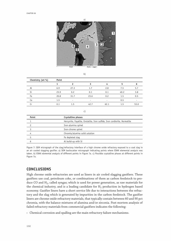
Interactions of the coal slag with the surface of the high chrome oxide refractory are not-ed in the backscatter SEM micrograph in Figure 7a, where EDAX analysis of elements in the slag and on the surface of the refractory are noted at specific points (Figure 7b). In looking at the chemistry, pronounced changes are noted in the slag away from the refrac-tory surface versus within the refractory pores (points 1 versus 5), which indicate that the concentration of Si has increased, and that of Fe has decreased. Also note that point 3 on the surface of a chrome/alumina grain in direct slag contact has decreased in Cr and increased in Fe content versus point 4, which has higher levels of Cr and no detectable quantity of Fe present. A distinct boundary exists related to the surface interaction of Fe with a chromia/alumina surface grain, which is evident in the backscatter SEM image of Figure 7a. When the Fe interaction layer on the grain surface is thicker than about 10 mi-crons, it appears to experience fracture, which could be caused by differences in volume expansion between the chromia/alumina solid solution phase and the iron chrome spinel that forms (listed as possible phases in Figure 7c). The breakup of the iron chromate layer on the surface may accelerate wear of the refractory in a flowing slag. It is also noted that surface alumina may leach from the grain into the slag, reducing in quantity when com-pared to the chemistry of the unexposed grain underneath (point 3 versus point 4 - Al content was 1.7 wt pct Al at point 3 versus 2.8 wt pct at point 4). On the surface of the refractory at the slag/refractory interface, iron aluminate was formed (point 2). It is not clear if this phase exists along the interface during high temperature operation of the gasifier, or it if crystallized from the slag during cool down.
1332
CHAPTER 09
a)
b)
Chemistry (wt %) Point
1 2 3 4 5 6
Al 6.9 27.3 1.7 2.8 7.5 5.7
Si 23.9 0.2 0.1 0.1 40.2 3.8
Fe 20.8 31.7 23.6 0.2 1.5 0.5
Ca 1.5 - - - 0.5 -
Cr 0.1 1.5 42.7 62.1 1.5 53.0
c)
Point Crystalline phases
1 Hercynite, Fayalite, Enstatite, Iron sulfide, Iron cordierite, Hermatite
2 Iron-alumina spinel
3 Iron-chrome spinel
4 Chromia/alumina solid solution
5 Fe depleted slag
6 Al build-up with Si
Figure 7: SEM micrograph of the slag/refractory interface of a high chrome oxide refractory exposed to a coal slag in an air cooled slagging gasifier. a) SEM backscatter micrograph indicating points where EDAX elemental analysis was taken. b) EDAX elemental analysis of different points in Figure 7a. c) Possible crystalline phases at different points in Figure 7a.
CONCLUSIONSHigh chrome oxide refractories are used as liners in air cooled slagging gasifiers. These gasifiers use coal, petroleum coke, or combinations of them as carbon feedstock to pro-duce CO and H2, called syngas; which is used for power generation, as raw materials for the chemical industry, and is a leading candidate for H2 production in hydrogen based economy. Gasifier liners have a short service life due to interactions between the refrac-tory and the slag which is generated by impurities in the carbon feedstock. The gasifier liners are chrome oxide refractory materials, that typically contain between 60 and 90 pct chromia, with the balance mixtures of alumina and/or zirconia. Post mortem analysis of failed refractory materials from commercial gasifiers indicates the following:
Chemical corrosion and spalling are the main refractory failure mechanisms.•
1333MOLTEN 2009. Santiago, Chile
Molten Slags Formed during Gasification of Carbon Feedstock...
Chemical corrosion of the high chrome oxide refractory liners is evidences by interac-•
tions between Fe in the slag and chromia in the refractory to form an iron chromate spinel, while Al in the refractory appears to leach into the slag. Chemical corrosion is a slow and predictable wear mechanism.
Spalling is caused by molten impurities in the carbon feedstock (slag) infiltrating pores •
of the high chrome oxide refractory. Thermal cycling of the gasifier leads to cracks that link and form large voids near the brick hot face where the slag has infiltrated. Thick sections of the refractory surface become separated from the main refractory lining as a result of these cracks, resulting in premature lining failure.
Slag interacts with the refractory, resulting in iron forming iron chromate on the grain •
surface. When this layer exceeds a certain thickness, fracturing in the slag diffusion layer occurs near or at the refractory/slag diffusion interface. Evidence exists that alu-minum diffuses from the refractory grain, forming an iron aluminate structure where the refractory grain contacts slag. It is not clear if the iron aluminate compound forms in the slag on cool down from elevated temperatures.
ACKNOWLEDGEMENTSThis report contains work of Kyei-Sing Kwong, Arthur Petty Jr., Hugh Thomas, and Rick Krabbe; all of the National Energy Technology Laboratory, U.S. Department of Energy.
REFERENCESGreenberg, S. & Poeppel, R. B. (1986). The Corrosion of Ceramic Refractories Exposed to Syn-
thetic Coal Slags by Means of the Rotation-Cylinder Technique: Final Report. Research spon-sored under USDOE/FE AA 15-10-10; April 1986; p. 66. [1]
Bakker, W. T., Greenberg, S., Trondt, M. & Gerhardus, U. (1984). Refractory Practice in Slag-ging Gasifiers. Amer. Ceram. Soc. Bulletin; Vol. 63, No. 7, pp. 870-876. [2]
Bonar, J. A., Kennedy, C. R. & Swaroop, R. B. (1980). Coal-Ash Slag Attack & Corrosion of Refractories; Amer. Ceram. Soc. Bulletin; Vol. 59, No. 4, 1980; pp. 473-478. [3]
Selvig, W. A. & Gibson, F. H. (1956). Analysis of Ash from United States Coals. USBM Bulletin, Pub. 567; pp. 33. [4]
Vassilev, S. V., et al. (2002). Low Cost Catalytic Sorbents for NOx Reduction. 1. Preparation & Characterization of Coal Char Impregnated with Model Vanadium Components & Petro-leum Coke Ash; Fuel; Vol. 81, pp. 1281-1296. [5]
Conn, R. E. (1995). Laboratory Techniques for Evaluating Ash Agglomeration Potential in Petro-leum Coke Fired Circulating Fluidized Bed Combustors. Fuel Processing Technology; Vol. 44, pp. 95-103. [6]
Bryers, R. W. (1995). Utilization of Petroleum Coke & Petroleum Coke/Coal Blends as a Means of Steam Raising. Fuel Processing Technology; Vol. 44, pp. 121-141. [7]
Bennett, J. P., et al. (2005). An Analysis of the Causes of Failure in High Chrome Oxide Refractory Materials from Slagging Gasifiers. UNITECR 05; Nov. 8-11, Orlando, FL.; Cer. Trans.; v. 180; J.D. Smith, ed.; pp. 935-939. [8]
