molecular mapping by low-energy-loss energy-filtered transmission...
TRANSCRIPT

Molecular Mapping by Low-Energy-LossEnergy-Filtered Transmission Electron MicroscopyImaging
Elisangela M. Linares, Carlos A. P. Leite, Leonardo F. Valadares, Cristiane A. Silva,Camila A. Rezende, and Fernando Galembeck*
Institute of Chemistry, Universidade Estadual de Campinas, Caixa Postal 6154, 13083-970, Campinas, SP, Brazil
Structure-function relationships in supramolecular sys-tems depend on the spatial distribution of molecules,ions, and particles within complex arrays. Imaging thespatial distribution of molecular components within nano-structured solids is the objective of many recent tech-niques, and a powerful tool is electron spectroscopyimaging in the transmission electron microscope (ESI-TEM) in the low-energy-loss range, 0-80 eV. This tech-nique was applied to particulate and thin film samples ofdielectric polymers and inorganic compounds, providingexcellent distinction between areas occupied by variousmacromolecules and particles. Domains differentiated bysmall changes in molecular composition and minor dif-ferences in elemental contents are clearly shown. Slightchanges in the molecules produce intensity variations inmolecular spectra that are in turn expressed in sets oflow-energy-loss images, using the standard energy-filteredtransmission electron microscopy (EFTEM) procedures.The molecular map resolution is in the nanometer rangeand very close to the bright-field resolution achieved forthe same sample, in the same instrument. Moreover,contrast is excellent, even though sample exposure to theelectron beam is minimal.
Analytical electron microscopy has already made an invaluablecontribution to current knowledge on materials properties, andthis is growing steadily thanks to the new techniques andprocedures that are being developed in many laboratories.1-4
Composition mapping is now practiced in different ways andin a large scale. Energy-dispersive X-ray (EDX) elemental mapsare currently very common, and they can be acquired even usingtable-top, low-cost scanning electron microscopes (SEM). Its useis often restricted to elements heavier than Na, but contemporaryequipment yields spectral data for lighter elements. Distributionmaps showing differences in the chemical environment of a givenelement can be obtained using wavelength-dispersive X-ray detec-
tion (WDX) and low-energy electron beams generated by field-emission sources in the scanning electron microscope (FESEM).Backscattering detection in the SEM has allowed the detectionof polymer domains differentiated by their chemical composition,e.g., polyurethane hard and soft domains, with a few nanometersof resolution,5 as well as the core-shell morphology in Stobersilica particles6 and poly(styrene-co-acrylamide) latex.7 The po-tential of SEM techniques has been largely increased recently withthe introduction of commercial focused-ion beam equipment (FIB-SEM).8
Other recent microscopy techniques are showing fine detailsof the distribution of domains characterized by differentiatedchemical ambient, even for light elements. This is the case ofscanning transmission X-ray microscopy (STXM) and X-rayphotoemission electron microscopy (X-PEEM), which are syn-chrotron-based. Soft X-ray spectromicroscopy techniques providechemical speciation at better than 50 nm spatial resolution basedon near-edge X-ray absorption spectral (NEXAFS) contrast.9
Methods for converting image sequences to quantitative maps ofchemical components were described and illustrated with applica-tions to characterization of wet biofilms, optimization of thesynthetic polymer microstructure, and studies of protein interac-tions with patterned polymer surface. Heat-treated polyacrylonitrile(PAN) fibers were imaged with a spatial resolution of 200 nm bySTXM at a third-generation synchrotron radiation facility usingNEXAFS spectra to produce chemical state images of the cross-sectioned fiber specimens. A clear “core-rim” structure wasobserved in the heat-treated fibers.10 An evaluation of NEXAFSimaging advantages and limitations was recently published.11 Incomparison to electron energy-loss spectroscopy coupled totransmission electron microscopy (TEM-EELS), NEXAFS micros-copy has much poorer spatial resolution, but it is more advanta-
* To whom correspondence should be addressed. Phone: +55-19-3521-3080.Fax: +55-19-3521-2906. E-mail: [email protected].
(1) Botton, G. Analytical electron microscopy. In Science of Microscopy; Hawkes,P. W., Spence, J. C. H., Eds.; Springer: New York, 2007; pp 273-405.
(2) Williams, D. B.; Carter, C. B. Transmission Electron Microscopy: A Textbookfor Materials Science; Plenum: New York, 1996; Vol. I.
(3) Botton, G. A.; Phaneuf, M. W. Micron 1999, 30, 109–119.(4) Egerton, R. F. Electron Energy-Loss Spectroscopy in the Electron Microscope;
Plenum Press: New York, 1986.
(5) Li, C.; Goodman, S. L.; Albrecht, R. M.; Cooper, S. L. Macromolecules 1988,21, 2367–2375.
(6) Costa, C. A. R.; Leite, C. A. P.; de Souza, E. F.; Galembeck, F. Langmuir2001, 17, 189–194.
(7) Teixeira-Neto, E.; Leite, C. A. P.; Cardoso, A. H.; da Silva, M. D. V. M.;Braga, M.; Galembeck, F. J. Colloid Interface Sci. 2000, 231, 182–189.
(8) Stokes, D. J.; Morrissey, F.; Lich, B. H. J. Phys.: Conf. Ser. 2006, 26, 50–53.
(9) Hitchcock, A. P.; Morin, C.; Zhang, X.; Araki, T.; Dynes, J.; Stoever, H.;Brash, J.; Lawrence, J. R.; Leppard, G. G. J. Electron Spectrosc. Relat.Phenom. 2005, 144-147, 259–269.
(10) Kikuma, J.; Warwick, T.; Shin, H.-J.; Zhang, J.; Tonner, B. P. J. ElectronSpectrosc. Relat. Phenom. 1998, 94, 271–278.
(11) Hitchcock, A. P.; Dynes, J. J.; Johansson, G.; Wang, J.; Botton, G. Micron2008, 39, 311–319.
Anal. Chem. 2009, 81, 2317–2324
10.1021/ac8024834 CCC: $40.75 2009 American Chemical Society 2317Analytical Chemistry, Vol. 81, No. 6, March 15, 2009Published on Web 02/17/2009
Dow
nloa
ded
by U
NIV
EST
AD
DE
CA
MPI
NA
S U
NIC
AM
P on
Sep
tem
ber
15, 2
009
| http
://pu
bs.a
cs.o
rg
Pub
licat
ion
Dat
e (W
eb):
Feb
ruar
y 17
, 200
9 | d
oi: 1
0.10
21/a
c802
4834

geous with regard to wet sample analysis. Both techniques arethen complementary.
Analytical techniques based on EELS have produced usefulinformation, especially in the case of light elements. This is donein a transmission electron microscope equipped with an electronmonochromator yielding energy-filtered (EFTEM)7,12,13 or elec-tron spectroscopy images (ESI-TEM).14-17 EELS is based on theinelastic scattering of electrons striking a sample, and the resultingspectra have three main features: zero-loss peak, low-loss region,and the characteristic absorption edges at higher energy, above100 eV.18 Absorption edges are useful for elemental analysis sincethey derive from the inner shell excitation of the sample elementsand their large cross sections account for an intrinsically highsensitivity that in turn allows the detection and quantification ofvery small amounts of any element, even in complex matrixes.
Most ESI-TEM results in the literature are elemental maps,obtained using arithmetic procedures on images acquired aboveand below the energy threshold for the excitation of inner shellelectrons, as for instance the K electrons in C, O, N, and otherelements. ESI-TEM elemental maps have been invaluable inelucidating polymer particles and film features so that most ofthe current microchemical and topochemical information onpolymers and polymer composites derives from these maps.19-22
The obvious next step in analytical microscopy is molecularmapping, the acquisition of images showing the positions ofdifferent molecular constituents within complex systems, eitherbiological or soft materials.
There are two possibilities for molecular mapping that can beimplemented using current standard configurations of transmis-sion electron microscopes fitted with EELS spectrometers, butneither has been widely exploited for polymer mapping, as yet.
The first is based on the use of the low-energy-loss spectralfeatures; this means, those derived from inelastic scattering inthe 2-80 eV energy range. Another possibility is the use of thespectral fine structure of EELS absorption bands and thus on thesame kind of information as NEXAFS, but this will be treated ina separate publication.
The low-energy-loss spectral region has been very useful inthe study of semiconductors and metals where it is usually
assigned to surface and bulk plasmon losses,23,24 but it has beenmuch less exploited in the case of dielectric molecular or solidionic compounds. This is likely due to a single cause: therespective electronic transitions have never received sufficientattention in the literature to create a body of widespreadknowledge. However, it is well established that at small scatteringangles and high kinetic energies, the most intense transitions arethose for which the matrix element of the electric dipole momentis nonvanishing.25 In the case of rare-earth compounds, wheredetailed spectroscopic information is available, the low-energy-loss region has been used with success, with an advantage overmapping based on inner shell transitions.26 By using valence-bandstates, maps with high spatial resolution yield quantitative el-emental composition at high acquisition rates. With the use ofGa 3d and In 4d transitions in the ε2 absorption spectrum (<40eV), quantitative elemental maps for III-V device structureswere produced for a GaInNAs/GaAs laser structure.
In carbon compounds, the spectral region of low-energy-lossshows some interesting spectral features. In general, inelasticcross sections are large, contributing to high detection sensitivity.In aromatic polymers, a characteristic peak is observed at ∼7 eV,which is assigned to an electronic π-π* transition.27,28 Thisspecific feature was applied to the stain-free imaging of polymers29
differentiating aromatic from aliphatic polymers, in spite of thefact that it is also well established that an aliphatic polymer suchas polyethylene can show a π-π* spectral feature under electronirradiation, due to hydrogen abstraction followed by reactionbetween adjacent main-chain carbon atoms.30 Recent advances incryoscanning TEM (STEM) associated to EELS were used toquantify the local composition changes, generating distributionmaps of water (ice), poly(dimethylsiloxane), and acrylate-vinylacetate copolymer in individual hybrid particles. The procedureconsists in acquiring spectra in different areas of the image,followed by calculation of local composition using multiple least-squares fitting of EELS spectra in the low-loss region.31,32 Aprevious work from this laboratory produced two kinds of newresults based on low-energy-loss EFTEM imaging. First, imagesfrom thick particles and particle aggregates were acquired, wheremorphological details were obtained even in successively thickerdomains by imaging at various energies in the 20-100 eV range.33
Moreover, mixed particle aggregates imaged in this same rangedisplayed a marked contrast. Contrast intensification, contrastinversion, or blurring was observed at different energies.
(12) Dohi, H.; Horiuchi, S. Langmuir 2007, 23, 12344–12349.(13) Valadares, L. F.; Linares, E. M.; Braganca, F. C.; Galembeck, F. J. Phys.
Chem. C 2008, 112, 8534–8544.(14) Newbury, D. E. J. Electron Microsc. 1998, 47, 407–418.(15) Elias, A. L.; Rodriguez-Manzo, J. A.; McCartney, M. R.; Golberg, D.;
Zamudio, A.; Baltazar, S. E.; Lopez-Urias, F.; Munoz-Sandoval, E.; Gu, L.;Tang, C. C.; Smith, D. J.; Bando, Y.; Terrones, H.; Terrones, M. Nano Lett.2005, 5, 467–472.
(16) Sun, X. H.; Li, C. P.; Wong, W. K.; Wong, N. B.; Lee, C. S.; Lee, S. T.; Teo,B. K. J. Am. Chem. Soc. 2002, 124, 14464–14471.
(17) Rippel, M. M.; Leite, C. A. P.; Galembeck, F. Anal. Chem. 2002, 74, 2541–2546.
(18) Goodhew, P. J.; Humphreys, F. J. Chemical analysis in the electronmicroscope. In Electron Microscopy and Analysis, 2nd ed.; Taylor & Francis:New York, 1988; pp 192-198.
(19) Braga, M.; Costa, C. A. R.; Leite, C. A. P.; Galembeck, F. J. Phys. Chem.2001, 105, 3005–3011.
(20) Amalvy, J. I.; Percy, M. J.; Armes, S. P.; Leite, C. A. P.; Galembeck, F.Langmuir 2005, 21, 1175–1179.
(21) Amalvy, J. I.; Asua, J. M.; Leite, C. A. P.; Galembeck, F. Polymer 2001, 42,2479–2489.
(22) Valadares, L. F.; Leite, C. A. P.; Galembeck, F. Polymer 2006, 47, 672–678.
(23) Hagelin, H. A. E.; Weaver, J. F.; Hoflund, G. B.; Salaita, G. N. J. ElectronSpectrosc. Relat. Phenom. 2002, 124, 1–14.
(24) Godinho, V.; Fernandez-Ramos, C.; Martınez-Martınez, D.; Garcıa-Lopez,J.; Sanchez-Lopez, J. C.; Fernandez, A. Eur. Phys. J.: Appl. Phys. 2008, 43,333–341.
(25) Lassettre, E. N.; Krasnow, M. E.; Silverman, S. J. Chem. Phys. 1964, 40,1242–1258.
(26) Gass, M. H.; Papworth, A. J.; Bullough, T. J.; Chalker, P. R. Ultramicroscopy2004, 101, 257–264.
(27) Swanson, N.; Powell, C. J. Phys. Rev. 1966, 145, 195–208.(28) Lavilla, R. E.; Mendlowitz, H. J. Phys. (France) 1964, 25, 114–118.(29) Arayasantiparb, D.; McKnight, S.; Libera, M. J. Adhes. Sci. Technol. 2001,
15, 1463–1484.(30) Ditchfield, R. W.; Grubb, D. T. Philos. Mag. 1973, 27, 1267–1281.(31) Kim, G.; Sousa, A.; Meyers, D.; Shope, M.; Libera, M. J. Am. Chem. Soc.
2006, 128, 6570–6571.(32) Kim, G.; Sousa, A.; Meyers, D.; Libera, M. Microsc. Microanal. 2008, 14,
459–468.(33) Valadares, L. F.; Braganca, F. C.; Silva, C. A.; Leite, C. A. P.; Galembeck,
F. J. Colloid Interface Sci. 2007, 309, 140–148.
2318 Analytical Chemistry, Vol. 81, No. 6, March 15, 2009
Dow
nloa
ded
by U
NIV
EST
AD
DE
CA
MPI
NA
S U
NIC
AM
P on
Sep
tem
ber
15, 2
009
| http
://pu
bs.a
cs.o
rg
Pub
licat
ion
Dat
e (W
eb):
Feb
ruar
y 17
, 200
9 | d
oi: 1
0.10
21/a
c802
4834

There are few examples of detailed studies on electron energy-loss, even for common molecules, and the observed transitionsin the low-loss region are not always understood in sufficientdetail.34 One paper concludes that “essentially all the featuresobserved in the discrete excitation region of CH4, C2H6, C3H8,and C4H10 can be reasonably assigned to Rydberg transitionsby using quantum defects and the transferability of termvalues”,35 and a recent paper stresses the lack of convergenceon the assignments of valence transitions with previous studies.Moreover, most of the Rydberg bands had not been previouslyassigned even for a simple molecule such as acetic acid, untilthe observation, analysis, and possible assignments of absorp-tion features between 12 and 20 eV were carried out for thefirst time in 2006.36 Nevertheless, by drawing from earlier workon photoelectron spectra of molecules,37,38 it is possible also toacknowledge contributions to low-energy-loss spectra from firstand higher ionization potentials, added to well-known outer shell(L, M) electron excitation.
Concerning the interpretation of images, detailed work byHowie39 concludes that “spatially valence loss spectroscopy canyield useful and quantitative information about local composition...on the nanoscale provided the geometry of the dielectric interfacesis accurately known.” In other cases, the simple assumption ofspectrum additive behavior may not always hold.
EFTEM image acquisition in the low-loss spectral region isvery interesting, because it requires only low beam exposure, incontrast to currently standard two- or three-windows techniquesused for elemental mapping. Moreover, since images are producedby inelastic electrons scattered at low angles, the resolution isnearly as good as in the bright-field images. Thus, the usefulnessof the technique depends only on the experimenter’s ability tounderstand the contrast based on known sample chemical,structural, and spectral features.
Thus, this technique holds the potential to produce molecularmaps within, e.g., polymer blends and nanocomposites, providedthat the involved constituents have different low-energy-lossspectra, as shown in this work.
MATERIALS AND METHODSLatex.Poly(styrene-co-hydroxyethylmethacrylate)[P(S-HEMA)]
latex was prepared by batch surfactant-free emulsion copolymer-ization of styrene and 2-hydroxyethyl methacrylate. A detaileddescription of this reaction is provided in refs 40 and 41. Othersamples of styrene-acrylate were commercial resins, Acronal 295D and Denvercril RA 193, supplied by BASF (Sao Paulo, Brazil)and Denver (Sao Paulo, Brazil), respectively.
Nanoparticles. Gold (Ted Pella, φ ) 4.8 ± 0.8 nm), Stobersilica, and aluminum phosphate nanoparticles were used. Silicananoparticles (33 ± 3 and 143 ± 14 nm diameter, as determined
by TEM) were prepared by the method of Stober et al.42
Aluminum phosphate pigment is a developmental product43
supplied by Bunge Company. Effective particle diameter inaqueous dispersion is 332 ± 98 nm, measured using photoncorrelation spectroscopy (PCS), in a ZetaPlus (Brookhaven Inst.Corp.) at 25 °C.
Particle Submonolayers. Lattices and nanoparticle disper-sions were cast and dried forming submonolayers. P(S-BA) andP(S-HEMA) lattices were diluted in water to ca. 0.005% solidcontent. Gold and Stober silica nanoparticles (φ ) 33 ± 3 nm)were dispersed in solutions containing poly(N-isopropylacryla-mide) (PNIPAM) and the surfactant sodium dodecyl sulfate (SDS).The final concentration of polymer and surfactant in the disper-sions was 10-3 g mL-1, and the particle concentration was0.006% (in weight). A mixture of styrene-acrylic latex (Den-vercril RA 193) and aluminum phosphate was prepared with20% total pigment volume concentration (PVC). An amount of76 g of aluminum phosphate slurry was added to 100 g of latexunder stirring using a Cowles disperser at 1000 rpm for 1 h.After that, this mixture was diluted in water until a finalconcentration of 0.006% solid content. A droplet (about 10 µL)of each sample was deposited on carbon-coated parlodion filmssupported on 400-mesh copper grids (Ted Pella) and allowedto dry at room temperature.
Blend Film Formation. P(S-HEMA) and P(S-BA) latticeswere mixed in a proportion of 3:7 w/w at room temperature,stirred for 30 min, and dried in a casting mold at 60 °C.
Ultramicrotomy. Ultrathin (ca. 60 nm) sections for TEManalysis were cut with a diamond knife (Drukker) using a LeicaEM FC6 cryoultramicrotome. The blend film was cut at -120 °C,using liquid N2. A drop of saturated sucrose was used to collectthe thin cuts from the cooled microtome and transfer them tothe microscope grids. After that, the grids were left floating indeionized water in a beaker for 5-10 min to wash out thesucrose.Theywerethenremovedanddriedatroomtemperature.
Stober colloidal silica (φ ) 143 ± 14 nm) was dried in a glassPetri dish. The dried silica was placed within a silicone rubbermold with 5 mm × 12 mm × 4 mm cavities and embedded in aPelco Eponate 12 resin (Ted Pella) using the recipe for mediumstiffness, followed by curing for 24 h at 60 °C. The embeddedsilica was cut at room temperature to nominal thickness of 50nm.
Electron Microscopy. Images were acquired using a CarlZeiss CEM-902 transmission electron microscope equipped witha Castaing-Henry-Ottensmeyer filter spectrometer. EFTEM wasused to obtain high-contrast image series when the slit was setto low-energy-loss and also to obtain bright-field images with lowchromatic aberration when the energy slit was selected to zeroloss. The series were obtained with an energy slit in the range of5-20 eV and set to short energy intervals in the 20-100 eV range.ESI-TEM was also used. Characteristic energy losses for C (303eV) were selected. The images were recorded using a Proscanhigh-speed slow-scan CCD camera, digitized (1024-1024 pixels,8 bits) and processed in the iTEM universal TEM imagingplatform.
(34) Huang, T.; Hamill, W. H. J. Phys. Chem. 1974, 78, 2077–2080.(35) Au, J. W.; Cooper, G.; Burton, G. R.; Olney, T. N.; Brion, C. E. Chem. Phys.
1993, 173, 209–239.(36) Leach, S.; Schwell, M.; Un, S.; Jochims, H. W.; Baumgaertel, H. Chem. Phys.
2006, 321, 159–170.(37) Dewar, M. J. S.; Worley, S. D. J. Chem. Phys. 1969, 50, 654–667.(38) Cooper, G.; Zhang, W.; Brion, C. E.; Tan, K. H. Chem. Phys. 1990, 145,
117–129.(39) Howie, A. Micron 2003, 34, 121–125.(40) Kamei, S.; Okubo, M.; Matsuda, T.; Matsumoto, T. Colloid Polym. Sci. 1986,
264, 743–747.(41) Tamai, H.; Fujii, A.; Suzawa, T. J. Colloid Interface Sci. 1987, 16, 37–41.
(42) Stober, W.; Fink, A.; Bohn, E. J. Colloid Interface Sci. 1968, 26, 62–69.(43) Galembeck, F.; Brito J. U.S. Patent 20060045831, 2006.
2319Analytical Chemistry, Vol. 81, No. 6, March 15, 2009
Dow
nloa
ded
by U
NIV
EST
AD
DE
CA
MPI
NA
S U
NIC
AM
P on
Sep
tem
ber
15, 2
009
| http
://pu
bs.a
cs.o
rg
Pub
licat
ion
Dat
e (W
eb):
Feb
ruar
y 17
, 200
9 | d
oi: 1
0.10
21/a
c802
4834

RESULTSThe first sample examined is a blend of two styrene-acrylic
polymers: P(S-BA) and P(S-HEMA). The first forms flexibleplastic films, whereas the second forms brittle colloidal crystals44
with little or no particle coalescence. Images of the isolatedparticles supported on the carbon-coated parlodion film are inFigure 1 with the corresponding EEL spectra: both peaks are atca. 20 eV, but the spectrum from the border of P(S-HEMA)particles also shows another band from 38 to 60 eV, peaking at48 eV. Beyond, P(S-HEMA) spectrum intensity decreases sloweras the energy increases, and it thus is higher from 60 eV up.Figure 1 also shows a bright-field micrograph from a thin blendfilm cut and its spectrum. It shows the P(S-HEMA) particlesdispersed in the P(S-BA) matrix, and the different electrondensities of the two polymers produce a pronounced contrast. Thespectrum of the blend shows contributions from both components,but these are not additive, which can be expected consideringthe detailed theoretical work by Howie.
The consequences of the spectral differences are clearly observedin the series of EFTEM images observed in Figure 2, where markedcontrast changes are observed in the micrographs obtained at 30,44, and 60 eV: there is contrast inversion between 30 and 60 eV, andalso a thick ring is seen around the particles at 44 eV. This is inagreement with the spectral features shown in Figure 1, and it allowstwo conclusions: the two different polymers are unequivocally
identified and the core-shell structure of the P(S-HEMA) particlesis revealed at 44 eV. The sharp contrast changes observed in theseimages are quite different from the low contrast observed in the Kabsorption threshold region shown in Figure 3 (280-286 eV) that isnormally used for carbon mapping. Indeed, this low contrast is notsurprising, considering that this sample is a thin film of a blend oftwo chemically similar polymers.
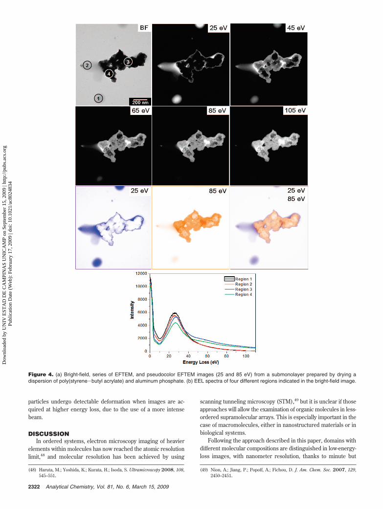
Figure 4 shows a set of micrographs and EEL spectra takenfrom four regions of a sample prepared with aluminum phosphateand styrene-acrylic latex particles. The phosphate aggregatesappear very dark in the bright-field image as well as in the 25 eVimage, whereas the coalesced latex particles form a gray film inthe bright-field micrograph. Above 25 eV, small morphologicaldetails can be observed within thick domains that are completelydark in the bright-field as well as in the 25 eV image. All EELspectra are dominated by single peaks within the 20-30 eV range,which are all very similar but with some qualitative differences.Spectral intensities of areas containing aluminum phosphatedecrease as the energy increases slower than the polymerspectrum. Spectra from regions containing aluminum phosphateand polymer domains cross at ca. 40 eV. This means thataluminum phosphate domains become increasingly brighter inthe 45-105 eV loss images. This observation is stressed in the25 and 85 eV overlay images, where the aluminum phosphateaggregates and the polymer domains appear orange and blue,respectively. Furthermore, this superimposed image shows clearlythe polymer surrounding phosphate aggregates.
(44) Galembeck, A.; Costa, C. A. R.; Silva, M. C. V. M.; Galembeck, F. J. ColloidInterface Sci. 2001, 234, 393–399.
Figure 1. Bright-field images and EEL spectra of (a) poly(styrene-hydroxyethyl methacrylate), (b) poly(styrene-butyl acrylate), and (c)poly(styrene-butyl acrylate)/poly(styrene-hydroxyethyl methacrylate) blend.
2320 Analytical Chemistry, Vol. 81, No. 6, March 15, 2009
Dow
nloa
ded
by U
NIV
EST
AD
DE
CA
MPI
NA
S U
NIC
AM
P on
Sep
tem
ber
15, 2
009
| http
://pu
bs.a
cs.o
rg
Pub
licat
ion
Dat
e (W
eb):
Feb
ruar
y 17
, 200
9 | d
oi: 1
0.10
21/a
c802
4834

In Figure 5, a bright-field image and a series of EFTEM imagesof a submonolayer of Stober silica nanoparticles are shown. Beforedrying on the TEM sample holder grid, the particles weredispersed in an aqueous solution of polymer (PNIPAM) andsurfactant (SDS) that adsorb at the nanoparticles surface.45,46 Thebright-field image shows small groups of nanoparticles, seemingly
separated, whereas the image at 25 eV shows particles apparentlylarger and contoured by a brighter ring (in the color pictures,darker colors mean brighter areas), revealing the presence of theadsorbed constituents. As the energy increases in the range from25 to 50 eV, the images change gradually losing contrast betweenparticle inner and outer regions. This effect is clearly seen inFigure 5 overlaying images at 25 and 50 eV.
Images of gold nanoparticles dispersed in the same polymer-surfactant solution are presented in Figure 6. The bright-fieldimage shows an area with many individual particles, but again,the images at lower energy (25 and 30 eV) reveal that particleinterstices are filled with adsorbed material, together with somestructured material deposited on the sample background. At 40and 50 eV, the particle interior is highlighted. Contrast inversionis observed at 25 eV and also overlaying images at 25 and 50 eV.For the sake of comparison, a carbon map is also presented, butit does not show the fine detail observed in the low-loss images.
Figure 7 gives a set of bright-field and low-loss EFTEM imagestaken from thin cuts of Stober silica embedded in resin. TheEFTEM images in the 25-65 eV range show differentiatedcontrast on the central region of some sliced silica particles,showing that particles are inhomogeneous. The core-and-shellnature of these particles is also clearly shown with good resolution,confirming results obtained in a previous work from this labora-tory.47
An advantage of the low-loss images is that particles are notdeformed during image acquisition, and the bright-field imagestaken before and after mapping are identical. However, the same
(45) Rezende, C. A.; Lee, L. T.; Galembeck, F. Langmuir 2008, 24, 7346–7353.(46) Costa, C. A. R.; Leite, C. A. P.; Lee, L. T.; Galembeck, F. Prog. Colloid Polym.
Sci. 2004, 128, 74–80.(47) Costa, C. A. R.; Leite, C. A. P.; Galembeck, F. J. Phys. Chem. B 2003, 107,
4747–4755.
Figure 2. Low-loss EFTEM images (24-100 eV energy loss) of a thin cut from a blend of poly(styrene-co-hydroxyethylmethacrylate) withpoly(styrene-butyl acrylate).
Figure 3. EFTEM images (280-286 eV energy loss) of a thin cutfrom a blend of poly(styrene-co-hydroxyethylmethacrylate) withpoly(styrene-butyl acrylate).
2321Analytical Chemistry, Vol. 81, No. 6, March 15, 2009
Dow
nloa
ded
by U
NIV
EST
AD
DE
CA
MPI
NA
S U
NIC
AM
P on
Sep
tem
ber
15, 2
009
| http
://pu
bs.a
cs.o
rg
Pub
licat
ion
Dat
e (W
eb):
Feb
ruar
y 17
, 200
9 | d
oi: 1
0.10
21/a
c802
4834
particles undergo detectable deformation when images are ac-quired at higher energy loss, due to the use of a more intensebeam.
DISCUSSIONIn ordered systems, electron microscopy imaging of heavier
elements within molecules has now reached the atomic resolutionlimit,48 and molecular resolution has been achieved by using
scanning tunneling microscopy (STM),49 but it is unclear if thoseapproaches will allow the examination of organic molecules in less-ordered supramolecular arrays. This is especially important in thecase of macromolecules, either in nanostructured materials or inbiological systems.
Following the approach described in this paper, domains withdifferent molecular compositions are distinguished in low-energy-loss images, with nanometer resolution, thanks to minute but
(48) Haruta, M.; Yoshida, K.; Kurata, H.; Isoda, S. Ultramicroscopy 2008, 108,545–551.
(49) Nion, A.; Jiang, P.; Popoff, A.; Fichou, D. J. Am. Chem. Soc. 2007, 129,2450–2451.
Figure 4. (a) Bright-field, series of EFTEM, and pseudocolor EFTEM images (25 and 85 eV) from a submonolayer prepared by drying adispersion of poly(styrene-butyl acrylate) and aluminum phosphate. (b) EEL spectra of four different regions indicated in the bright-field image.
2322 Analytical Chemistry, Vol. 81, No. 6, March 15, 2009
Dow
nloa
ded
by U
NIV
EST
AD
DE
CA
MPI
NA
S U
NIC
AM
P on
Sep
tem
ber
15, 2
009
| http
://pu
bs.a
cs.o
rg
Pub
licat
ion
Dat
e (W
eb):
Feb
ruar
y 17
, 200
9 | d
oi: 1
0.10
21/a
c802
4834

decisive differences in the respective electronic spectra that derivefrom the overall electronic structure.
Thus, the present approach offers significant advantages innoncrystalline systems, especially in the case of macromolecularcompounds, where the researcher cannot count on the use ofgeometric parameters related to well-defined molecular dimen-sions to gain information, as is often done in molecular imagingby atomic force microscopy (AFM) or STM. These advantagesare shared with the photoemission methods, but these currentlyhave lower spatial resolution than EFTEM or ESI-TEM.
The availability of EEL spectra in the 1-100 eV region is usefulbut not essential for differentiating domains in the low-energy-loss region. In Figures 4-7, spectra are not shown for the systems,but it is still possible to interpret the images unequivocally,provided at least one material presents a well-defined geometry.
An excellent contrast is observed within different domains,even though the low-energy-loss spectra for molecular solids havefew sharp features. Moreover, not only contrast is obtained at agiven energy-loss but also the contrast patterns change with theimaging electron energy, producing a large amount of detailedinformation irrespective of the sample complexity. Thus, thistechnique is especially suitable for discovering differentiatedmolecular domains in a complex sample.
The series of EFTEM images of P(S-HEMA)/P(S-BA) blendfilm shows the sensitivity of this technique to contrast materialswith similar chemical compositions. Both materials are copolymersof styrene and acrylate monomers, and they produce low contrastin the K threshold region. However, using low-energy-loss EFTEMeach polymer phase is easily observed as well as the P(S-HEMA)core-shell structure. Core-shell composition difference is alsorevealed in the images of ultramicrotomed Stober silica particles.In the case of polymer layers adsorbed on the surface of goldand silica nanoparticles, the contrast between the inner and theouter regions of the particles in EFTEM images change graduallyas the energy increases from 25 and 50 eV, providing clearidentification of the adsorbed material, with good spatial resolution.
Figure 5. Bright-field and a series of EFTEM images from asubmonolayer of Stober silica nanoparticles dispersed in PNIPAMand SDS and dried at room temperature. The last shot on the rightresults from the overlay of the images at 25 (green) and 50 eV(yellow).
Figure 6. Bright-field and a series of EFTEM images from asubmonolayer of gold nanoparticles dispersed in PNIPAM and SDSand dried at room temperature. In the last shot there is a carbon mapof the same field.
Figure 7. (Top left) Bright-field image and low-loss EFTEM images(25-95 eV energy loss) of embedded Stober silica thin cuts.
2323Analytical Chemistry, Vol. 81, No. 6, March 15, 2009
Dow
nloa
ded
by U
NIV
EST
AD
DE
CA
MPI
NA
S U
NIC
AM
P on
Sep
tem
ber
15, 2
009
| http
://pu
bs.a
cs.o
rg
Pub
licat
ion
Dat
e (W
eb):
Feb
ruar
y 17
, 200
9 | d
oi: 1
0.10
21/a
c802
4834

Images with contrast due to differences in the molecularcomposition at nanometer resolution are thus obtained. This canbe done even in cases where little or no previous information isavailable on the sample constituents. The achieved resolutionmatches the excellent results that have been obtained by AFM50
but with an advantage in the case of systems that are in an earlystage of investigation.
The expression “molecular mapping” was previously used, butthe involved techniques employed other approaches that sufferfrom various limitations and found only a rather limited use.51,52
Given the characteristics of the present technique, it can well findwidespread application.
In conclusion, there is no barrier to finding out the distributionof different molecular constituents in a sample, with at leastnanometer resolution. Achieving atomic resolution will largelydepend on the experimenter’s ability to image soft materials withhigh-energy beams, without introducing excessive sample dam-age. This is not a simple task, but it is certainly worthwhile, forthose interested in learning about the structural arrays existingin natural or synthetic complex materials to understand theirproperties and possible functions.
CONCLUSIONSEFTEM serial imaging in the low-energy-loss spectral region
allows the observation and distinction of domains with sizes inthe nanometer range and with small differences in chemicalcomposition, without staining the sample. This is done under lowsample exposure to the electron beam without introducingdetectable sample damage even in very soft materials, producingaccurate molecular distribution maps.
ACKNOWLEDGMENTE.M.L., C.A.R., C.A.S., and L.F.V. express thanks for fellow-
ships from Fapesp, CAPES, and CNPq. This is a contribution fromthe Millennium Institute for Complex Materials, PADCT/CNPq.F.G. acknowledges useful discussions with Professors Oscar Malta(Recife) and Gerardo G. B. de Souza (Rio de Janeiro).
SUPPORTING INFORMATION AVAILABLE(S1) Description of two sample preparation procedures (a)
poly(styrene-co-hydroxyethyl methacrylate) [P(S-HEMA)] latexand (b) Stober silica, and (S2) a full set of pictures from whichFigure 2 was extracted. This material is available free of chargevia the Internet at http://pubs.acs.org.
Received for review November 24, 2008. AcceptedJanuary 15, 2009.
AC8024834
(50) Kienberger, F.; Ebner, A.; Gruber, H. J.; Hinterdorfer, P. Acc. Chem. Res.2006, 39, 29–36.
(51) Martin, J. M.; Vacher, B.; Ponsonnet, L.; Dupuis, V. Ultramicroscopy 1996,65, 229–238.
(52) Diociaiuti, M.; Falchi, M.; Paoletti, L. Microsc., Microanal., Microstruct.1995, 6, 33–40.
2324 Analytical Chemistry, Vol. 81, No. 6, March 15, 2009
Dow
nloa
ded
by U
NIV
EST
AD
DE
CA
MPI
NA
S U
NIC
AM
P on
Sep
tem
ber
15, 2
009
| http
://pu
bs.a
cs.o
rg
Pub
licat
ion
Dat
e (W
eb):
Feb
ruar
y 17
, 200
9 | d
oi: 1
0.10
21/a
c802
4834