moisture migration- concrete slab-on-ground … · moisture migration-concrete slab-on-ground ......
TRANSCRIPT

PORTLAND CEMENT ASSOCIATIONRESEARCH AND DEVELOPMENT LABORATORIES
MOISTURE MIGRATION-
CONCRETE SLAB-ON-GROUND
CONSTRUCTION
By H. W. Brewer
Reprinted from the Journal of the PCA
Research and Development Laboratories
Vol. 7, No. 2, 2-17 (May, 1965)
@ po&nd Cement Association, 1965

MOISTURE MIGRATION — CONCRETE
SLAB-ON-GROUND CONSTRUCTION
By H. W. Brewer
PORTLAND CEMENT ASSOCIATION
RESEARCH AND DEVELOPMENT LABORATOWES5420 Old Orchard Road
Skokie, Illinois 60076

Moisture Migration –
Concrete Slab-on-Ground Construction
ByH. W. Brewer, Development EngineerProducts and Applications Development
SectionResearch and Development LaboratoriesPortland Cement Association
sYNOPSIS
Concrete slab-on-ground has become a widely used
method of construction. Moisture migration from suchdabs is of importance primarily because of its effecton certain types of floor coverings.
This study reports data on i 4 I specimens cast from
29 mixes covering a wide range of concrete quality.The program included exposure conditions varying
from water-in-contact to drying only, as well as the
effect of admixtures, vapor barriers, and gravel capil-lary breaks. Several differen~ test procedures werestudied in the course of the investigation.
Good correlation was found between moisture migra-
tion and water—cement ratio (w/c ), flow increasingdirectly with w/c. Admixtures had little effect onmoisture migration measured by these methods. Vapor
barriers and gravel capillary breaks produced little orno change in the measured flow at early ages, butreduced the flow at later ages.
The superior resistance to moisture migration ofgood quality concrete, relative to that of lower quality
concrete, was amply demonstrated in this study re-
gardless of time or type of exposure. Analysis of the
data established that outflow measurements rather thanInflow measurements properly evaluate moisture migra-
tion at early ages. The out+low measurements indicated
that rate of moisture loss at early ages is 4 to 10 timesthe flow through the concrete.
INTRODUCTION AND BACKGROUND
Initially the extensive use of concreteslab-on-ground as a method of constructionwas employed in warm and dry areas, andasphalt tile was the common floor covering.Later, less permeable coverings were adopt-ed and slabs were also constructed in areaswith less favorable soil and climatic condi-tions. These circumstances have placed
greater emphasis on the need for infor-mation dealing with moisture migrationthrough concrete slabs.
The keen interest and the need for tech-nical information regarding concrete slab-on-ground is evidenced by five reports onthe subject issued since 1955 by the Na-tional Academy of Sciences—National Re-search Council through the Building Re-search Advisory Board.
“Slab-on-Ground Construction for Resi-dences,” NAS-NRC Publication 385 (June1955),( 1)* discusses site preparation, needfor capillary breaks and vapor barriers,slab design, and insulation. The report ter-minates with 10 research recommendationsindicating the need for much technical in-formation.
“Vapor Barrier Materials for Use withSlab-on-Ground Construction,” NAS-NRCPublication 445 (May 1956),( 2) is a reportdescribing required properties of vapor bar-riers and pertinent test methods to evaluatethese properties.
“Effectiveness of Concrete Admixturesin Controlling Transmission of MoistureThrough Slabs-on-Ground,” NAS-NRCPublication 596 (July 1958),(3) describes atest procedure to evaluate the effectivenessof admixtures on moisture control. Thecommittee knew of no admixture that
● Numbers in parentheses refer to references atend of paper.
Journal of the PCA Research and

would be sufficiently effective to replace ei-ther a vapor barrier or granular base wheresuch protection was needed.
“Design Criteria for Residential Slabs-on-Ground,” NAS-NRC Publication 657(March 1959),(+0 recommends a procedurefor analysis of structural slabs. The com-mittee delineated four major types of slabsand recommended particular types for var-ious combinations of site and climatic con-ditions.
“Protection from Moisture for Slab-on-Ground Construction and HabitableSpaces Below Grade,” NAS-NRC Publica-tion 707 (February 1959), (5) describes sitepreparation and also use of capillarybreaks, vapor barriers, and good qualityconcrete for controlling moisture. It also in-cludes recommendations regarding insula-tion and finish floor coverings.
The purpose of all of these BRAB re-ports was to provide information thatwould be helpful to the Federal HousingAdministration in establishing MinimumProperty Standards on this subject and indefining needed research activities.
Although there are numerous referencesin the literature to moisture migrationthrough construction materials, few ofthese are directly applicable to concrete.One of the most comprehensive investiga-tions is that made by Professor C. E. Lundat the University of Minnesota for the U.S.Navy Bureau of Yards and Docks.( 13JThestudy included three different types of con-crete over six different types of soil. Twoadmixtures, two surface coatings, and amoisture barrier were studied. This investi-gation showed the advantage of using highquality concrete and of providing a capil-lary break beneath the slab. None of theadmixtures or surface treatments was bene-ficial. Heavy asphalt-impregnated and lam-inated felt was a very effective moisturebarrier,
A study by the Forest Products Labora-tory for the Housing and Home FinanceAgency(7) included the use of capillarybreaks and vapor barriers beneath the slab.However, only one specimen was providedfor each of six test conditions, and this fact,together with some apparent inconsisten-cies, seriously limits the usefulness of thedata.
Kocataskin and Swenson(s) used both wa-ter and water vapor test procedures to eval-uate waterproofing additives in lean (1:6
and 1:7) portland cement mortars. Theyfound that an integral bituminous emul-sion was an effective waterproofing mate-rial, when tested by the water vapor proce-dure, and that ammonium stearate waseffective in the leaner mortar. When testedunder saturated conditions with 32 centi-meters of water on the disk, none of thewaterproofing additives was beneficial.
Powers, Copeland, Hayes, and Mann(g)have discussed the permeability of cementpaste and have shown the advantage of lowwater—cemen t ratio and continued moistcuring in reducing permeability.
A recent article by Griffin and Henryt 1o)is concerned primarily with salt contamina-tion of concrete, but concludes that water-vapor transmission increases with an in-crease in water—cement ratio.
Tests and experience have shown thatdifficulties normally encountered with con-crete floors on grade can be largely elimi-nated by adherence to good constructionpractice. The recommendations of theBuilding Research Advisory Board as givenin reference 5 provide good advice. Carefulselection of site, provision for proper drain-
age, and observance of the fundamentalrules for making concrete will eliminatemost of the problems. However, the factthat concrete contains water which it losesupon drying, and that under certain con-ditions some water will pass through it,poses a problem that can be only partiallyalleviated by good construction procedures.
The concern over moisture migrationthrough or from a concrete slab is not withrespect to its effect on the slab, but its effecton resilient tile, wood or other flooring,rusting of metal, etc. Retention of water orpassage of water through concrete is gen-erally not detrimental to the concrete. Theconcrete slab should be moist cured for sev-eral days after casting, and strength andimpermeability of the concrete are bothfurther improved by longer curing. On theother hand, the concrete surface should berelatively dry prior to installation of mostfloor coverings. Under usual constructionpractice, floor coverings are installed with-in a few weeks after the concrete slab hasbeen cast, entrapping much of the originalmix water in the concrete, which later con-tributes to buckling of wood floors andaffects adversely the adhesives used withsome of the resilient tile. Under these con-ditions, the moisture outj90w from the sur-
Developmenf La60rafories May 7965 3
—

.
face of the concrete at early ages is moreimportant than the relatively stable mois-ture flow through the concrete at later ages.
A review of the literature indicates thatmoisture migration has been reported asinflow to certain types of specimens andoutflow from other types. After extendedexposure periods these values tend to be-come equal; but the outflow after onlyshort exposure periods is much higher thanthe inflow. 0utj70w is the total moistureleaving the surface of the concrete slab,and consists of loss of mix water due to dry-ing in addition to the moisture passingthrough the slab. Most of the outflow fromconcrete slabs measured during the first fewweeks results from moisture losses due todrying. Only small quantities of moisturepass through good quality concrete orthrough slabs protected by efficient vaporbarriers.
A testing program was initiated coveringvariables believed pertinent to the study.Initial tests were made on slabs cast over acompacted soil base with and without afour-inch-gravel capillary break directly be-neath the slab. The use of various vaporbarriers was also included. The quality ofconcrete was varied over a wide range withboth sand-gravel and expanded shale aggre-gates. In later test series the compacted soilbase was eliminated and slabs were exposeddirectly to either water vapor or water-in-contact. Several admixtures reported aspossibly effective in reducing moisture mi-gration were included. This report is basedon 141 specimens cast from 29 concretemixes. Erratic data, usually accompaniedby leakage, eliminated some other speci-mens. A Type I cement that was a blend ofseveral brands was used in all concretes.
The testing program developed intothree major series. The initial testing pro-cedures were not entirely satisfactory, butwere improved as the program progressed.In the first series, concrete slabs were castover soil, or soil plus gravel, in 16-galloncontainers, with a water level maintained16 inches below the bottom of the slab. Inthe second series, concrete specimens werecast in the top of 14-quart pails as suggest-ed by a Building Research Advisory BoardCommittee. (3) Two modifications of the rec-ommended procedures were necessary be-fore satisfactory results were obtained. Inthe third series, difficulties encountered inthe first two series were eliminated by cast-ing specimens in one-gallon cans and test-
ing in a closed system. These various speci-mens, procedures, and results are describedfor each series.
Flow is reported in grains per hour per~quare foot. If the flow in pounds of water1s desired the values shown should be di-vided by 7000.
SERIES I
Test Procedure
The first of the various test procedureswas developed in collaboration with repre-sentatives of a government housing agency.As a representative condition for prelimi-nary study, it was decided that the concreteslab should be 16 inches above water level,on a clay soil subbase, and that a gravelcapillary break and vapor barriers shouldbe included as variables.
The test specimens and procedures weresimilar to those used by the Forest ProductsLaboratory. (7) Metal containers 26 incheshigh and 14 inches in diameter were paintedwith rust inhibitor and fitted with glass wa-ter column gages as shown in Fig. 1. A 4-inch layer of coarse gravel was placed inthe bottom and covered with expandedmetal lath and falter paper to provide awater reservoir to facilitate water adjust-ments. The containers were filled with claysoil compacted at optimum moisture con-tent to maximum density. Half of thesecontainers had a 4-inch layer of s/s to l-inchgravel and two layers of cheesecloth abovethe soil. Ten of the 24 containers had a 4-inch metal extension which clamped overvapor barriers of 4-roil polyethylene or 55-pound roofing felt.
Four-inch-thick concrete slabs 13.5 in. indiameter were cast in the top of each con-tainer. These slabs included both normalweight and lightweight concretes of a widerange of cement contents. Concrete mixand strength data are given in Table 1.One specimen from each concrete was caston the soil and another was cast on thegravel. A IA-inch annular space between theconcrete and painted metal container wasfilled with an asphaltic rubber sealing com-pound after the concrete had hardened.In addition, 10 specimens from the 0.70w/c sand-gravel concrete (five on soil, andfive on gravel) were cast above two differentvapor barriers.
Moisture migration was determined bymeasuring the water required to maintaina water surface in the glass column 16
Journal of the PCA Research and

TABLE 1—MIX DATA AND PHYSICAL PROPERTIES — SERIES 1 CONCRETES
Cement ContentMix
Comp. Str.,w/c Unit Wt,
E x 106, psiAir Slump, psi at at
No. lbs/cu yd bags/cu yd lbs/cu ft Content, TO i.. 28 days 28 days
Sand-Gravel Concrete
A 0.51 438 4.7 152.3 1.2 2.9 5300 4.1B 0.62 376 4.0 152.1 1.4 2.9 4200 4.0
c 0.70 332 3.5 151.4 1.4 2.5 3200 3.7
D 0.89 290 3.1 149.5 1.4 3.1 2060 2.3
Expanded Shale Concrete
E — 571 6.1 96.7 3.7 1.9 6100 2.4
F — 463 4.9 95.0 3.8 1.8 4360 2.5
G 385 4.1 92.6 4.0 1.4 2820 2.1
inche8 below the bottom of the concreteslab. Erratic readings, which were soonobserved, were attributed to entrapped airin the soil or gravel and to changes inbarometric pressure. These 340-lb speci-mens were tipped periodically to removethe entrapped air, especially after rapidchanges in barometric pt’essure. Tests werecontinued for 16 months when stable flowswere obtained. These specimens were test-ed in an environment controlled to 73 Fand 30 percent relative humidity.
2C
N—
o. grease drums, 16gol. capacity
— 14”+
GRAVEL or CLAY.—— ——— —-— — ——— I
GRAVELe
Without Vapor Barrier
Fig. I — FPL-Type
Series I Results end Discussion
Considerable difficulty was encounteredwith these specimens due to the unknownquantities of water absorbed by the system,to leakage, and to the barometric effect thatcaused large variations in the water level.Of the 50 specimens cast in this series, only24 stabilized to the extent that data wereconsidered to be reliable. The remaining26 specimens were discarded and no otherreference is made to them in this report.As a result of this experience (and also re-
t
———————————-
T‘w—
i
Glasstube
/’-Level
/=$LCOMPACTED CLAY
filter ~a~er andexpan e metal Io?h
GRAVEL
With Vapor Barrier
Moisture Migration Apparatus.
Development Laboratories May 1965 5

suits from Reference 7), this test procedureis not recommended for moisture migra-tion studies. Another objection to this testmethod, as will be discussed later, is thatthe test measures the inflow to the totalsystem and not outflow from the surface.However, the effects of the gravel capillarybreak and of the vapor barriers appear tobe established reliably, as is discussed inthe following sections.
Fig. 2 shows the moisture inflow for thesand—gravel concrete slabs of various water—cement ratios cast over soil with and with-out a gravel capillary break. The initialinflows were erratic but became more con-sistent after the specimens were tipped toremove entrapped air. After 16 months theflows varied only from 1.1 to 1.8 grainsper hour per square foot for the various
specimens, with the concretes of higher wa-ter—cement ratios having higher flows at allages. The gravel layer reduced the flow by10 to 25 percent.
Fig. 3 shows the effect of vapor barrierson moisture inflow with and without gravelcapillary breaks for concrete of 0.70 w/c.The two vapor barriers, 4-roil polyethyleneand 55-lb roofing felt, gave similar results,and the curves shown represent averagesof both types.
The gravel capillary breaks reduced theinflow both with and without the vaporbarrier. The vapor barrier plus gravel lay-er greatly reduced inflow during the entiretest. Examination after completion of thetest showed that a layer of free water hadcollected between the soil and polyethylenefilm. Almost continuous patterns of car-bonated material were formed on the con-crete side of the polyethylene above thegravel. The specimens protected by the 55-Ib roofing felt showed less moisture be-tween the vapor barrier and soil, but theroofing was decomposed, tore easily, andwas partially coated with slime and mold.
The top surface of one of the felt vaporbarrier specimens was coated with polyestertwo months before the end of the test. Themeasurements indicated no reduction of in-flow during this time; but when the slabswere removed from the containers and im-mersed in water to determine the percentof saturation, this specimen was 64 percentsaturated compared to the other three spec-imens which were only 46 percent satu-rated. This result shows that an imperviouscoating on the top surface caused the mois-ture content to increase in the concrete,and that this occurred even with the vaporbarrier above a gravel layer. The six slabsabove the polyethylene film were only 37
I I I I I 1 I
/
\\\\
\ Slabs cast an soil
With a gravel layer
\
---—- ____---——_ ._— — = = —.—.—-—————= — — ..—_._—
I I I I I I I I2 4 6 8 10 12 14 16
MONTHS
Fig. 2 — Effect of Water-Cement Ratio and Grewel Layer.Series I
b Journal of the PCA Researcft and

[ , t r T 1 I
/
\\+Soil
Wc 0.70
\
FSoil $ Gravel
\,
Soil # Vapor Barrier
~\
. <_s:l~Gravel ~ Vapar Borrier -—-—.~
--- -——— . “~——— ——— —.
1 I I I 1 I
1
2 4 6 8 10 12 14 16
MONTHS
Fig. 3 — StTect of Gravel and Vapor Barrier.
Series 1
percent saturated at the end of the test.six slabs without vapor barriers were from67 to 73 percent saturated.
Lightweight aggregate concretes showedconsiderably less flow (Fig. 4) than mostof the sand—gravel concretes. The slabs castover soil showed reduced inflow with in-creasing cement content. This relationshipwas not well defined for the companionslabs cast over soil with a gravel capillarybreak, as all of the curves fell into a rela-tively narrow band. Comparison of thecurves of Fig. 4 reveals the advantage ofthe gravel capillary break, particularly forslabs with lower cement content.
SERIES 2
Test Procedures
The second series of tests was conductedusing a test procedure suggested by Build-ing Research Advisory Board Subcommit-tee 11 on Admixtures. ta) Galvanized pails of14-quart capacity were fitted with twoopenings and a metal screen covered byfilter paper upon which concrete was cast,as shown by Fig. 5. Concrete samples castin the upper portion of the pail could betested either with water in contact with theslab, or with the concrete exposed to watervapor. The first phase of this test proceduredid not prove satisfactory because of the
generation of hydrogen gas within the as-semblage due to a reaction of the zinc inthe galvanized lining. This difficulty wasovercome by coating all interior metal parts(pail, screen and supports) with epoxy res-in. Three groups of specimens were testedusing this modified BRAB-type procedure.
This series consisted of five concretemixes of different w/c ratios with andwithout a polyethylene vapor barrier. Im-portant properties of mixes are given inTable 2.
Two additional vapor barriers, 32-roilABS plastic and 55-lb roofing felt, werealso included with specimens of 0.45 and0.55 w/c. Epoxy resin was used to attachthe vapor barriers to the sides of the pail.The pail above the vapor barrier wascoated with cup grease as a means of ob-taining a seal between the concrete andcontainer for the first four concretes, whileepoxy resin was used as a more positiveseal for the 0.41 w/c concrete. Wax wasplaced in the preformed groove around theperiphery of the concrete after seven dayscuring.
Concrete slabs of 0.45 and 0.55 w/c werefirst exposed to water vapor for 50 days inan environment controlled to 73 F and 30percent relative humidity. Freshly boiledand cooled water was added to a depth of
Development Laboratories May 1965 7

TABLE 2—MIX DATA AND PHYSICAL PROPERTIES—SERIES 2 CONCRETES
Cement Content Comp.St,., E x 106, psiMI?. w/c Unit Wt, Air Sl::p,No.
psi atlb,/cu yd b.o,/cu yd lbs/cu ft Content, % 28 days 28 ;’OYS
H 0.45 478 5.1 153.6 1.9 I ,5 6820 5.0
J 0.55 465 5.0 150,0 1.6 8.o 5120 4,6
K 0.68 282 3.0 140.8 6.2 7,8
L 0,99 284 3.0 147,0 1.0 7.4 1300 —
M 0,41 507 5.4 151.2 4,0 I .5 6680 4.2
Admixture% K = AEA-1, M = AEA-2.
two inches in the bottom of the pail, leav-ing an air space between the water and thebottom surface of the concrete. The glasswater columns were capped to prevent lossof moisture. At the end of this period thepails were completely filled with water andall entrapped air was carefully removedfrom beneath the slab. Testing continuedfor 165 days in a room controlled at 73 Fand 50 percent relative humidity. Moisturemigration was determined by weight losswhile the specimens were exposed to watervapor, and by measuring the water added(inflow onlv) while the s~ecimens were
Concretes of 0.68 and 0.99 w/c weretested with water-in-contact for 138 days,then a portion of the water was drainedout and the test with water vapor only wascontinued for another year. Companionspecimens were subjected to water vaporexposure for 50 days.
To obtain an estimate of water loss dueto drying only, additional specimens werecast, cured seven days, and then sealed onthe bottom and sides with several coatsof polyester resin. These specimens werestored beside the others in the 50 percentrelative humiditv room and were weighed\ ., .
subjected to water-in-contact. periodically for 500 days.
Slabs Cast Over Sail and Gravel
W._Al ,Jy6,uyd
—\/0 \/ Slob”s Cast Over Sail
‘~bagsiiyd”I I I I 1 I I
o 2 4 6 8 10 12 14 16
MONTHS
Fig. 4 — Effect of Cement Content and Gravel Layer for Lightweight Concrete.Series I
Journal of the PCA Research and

d
d
Fig. 5— Moisture Migration Test Apparatus.Series 2
●Dimensions of poil need not be exactly m shown.
Development Laboratories May 19659

As testing of this series continued, it be-came apparent that a small amount of leak-
age was occurring in a few of the speci-mens. All specimens with obvious leakagewere discarded, and a further attempt wasmade to refine this particular testing pro-cedure.
A portion of the program was repeatedusing nine specimens of concrete at 0.41w/c, with and without vapor barriers, andwith the slabs sealed in the pails with epoxyresin.
To eliminate any possibility of water lossby gravity from the fresh concrete and toproduce a more uniform bottom surface,55-lb roofing felt was placed on top of themetal grid and the edges were sealed withcup grease. The upper four inches of thecontainers was also coated with cup grease.After the concrete had cured three days,the slabs, vapor barriers, and metal gridswere removed from each container. Allslabs were weighed, then new vapor bar-riers were attached at the edges of fiveslabs with epoxy resin. Polyethylene wasattached to three slabs, and 55-lb roofingfelt was attached to two slabs. After the
16
(A]% O 4514 1’””’(B)%055
8
~; :y e
ao. I
[cl % 068\ ‘,: ,O)vc ~,9
●- 16 -;
9 \\\
: 14 -\: \
“..- ~-–WATER-, N-\ cONTACT
12 -i
:L b
\$ WATER-IN. CONTbCT ‘\: 10 - 1, ‘.,. . . .
:8\ ‘“\
\\
6 I\\, ‘t.,
+W4TER V&POR
‘\
4 ------- ‘.s.
WATER“&pOR ---
2 ‘7 -.–_–I LDRIED ONLY [
I00I
10 20 30 +0 50 0 10 20 30 40 50DAYS
Fig. 6 — Effects of Water-Cement Ratios and
Vapor Barriers Under Various Exposures.Series 2
TASLE 3—MOISTURE OUTFLOW FROM SPECIMENSWITHOUT VAPOR SARRIER—SERIES 2—AGE 50 DAYS
Moisture Outflow, nraina/hr/sq f!Wlc
Woler Vapcf W .ter-in-COntact
1
0.45 1.0 —
0.55 1.2 —
0.6s 2.2 3.3
0.99 2.6 7.8
epoxy had hardened, the upper four incheso~ ea-ch container was cle;n-ed and coatedwith epoxy, and while the epoxy was stilltacky each slab was carefully fitted into itsown container. As soon as the epoxy hadset, freshly boiled and cooled water wasadded to each container. After anotherthree days of curing under polyethylenefilm, wax was placed in the periphery ringand freshly boiled and cooled water wasadded to bring the water level in the glasstube to three inches below the top surface.All air entrapped on the lower surface ofthe concrete was removed through the vent,using a bottle brush.
Moisture outflow was computed fromthe sum of the water added to maintainthe constant head plus any loss in weightfrom the specimen. Water was added dailyand weights were taken weekly. Controlspecimens were coated with polyester onthe sides and one surface to determine themoisture loss due to drying only.
Series 2 Results and Discussion
Test results obtained during the first 50days of the various exposures (Fig. 6), showthat outflow increased as w/c increased.During the first few weeks high flows weremeasured on all specimens, but, at age 50days, outflow had reduced to the ratesshown in Table 3. Specimens exposed withwater-in-contact had considerably greateroutflow than those exposed to water vapor.
There appeared to be little difference inflow between specimens that were dryingonly (Fig. 6c) and those that were exposedto water vapor. This indicates that withwater-vapor exposure the loss from the sur-face was due almost entirely to loss of cwigi-nal mixing water, with very little moisturepassing through the slab.
Outflow from specimens cast on vaporbarriers was generally slightly greater atearly ages than from specimens without va-
10 Journal of the PCA Research and

por barriers. This apparent anomaly occursbecause the major portion of the water lossat early ages is due to evaporation of themix water. When vapor barriers were notused, more mix water drained from thefresh concrete into the pail thereby reduc-ing the water content and w/c ratio inthese slabs. However, at later ages, thesevapor barriers reduced the flow for water-in-contact exposure. After the initial expo-sure of 50 days to water vapor, the speci-mens with 0.45 w/c were subjected towater-in-contact. At age seven months, thesespecimens had stabilized with the followingvalues for inflow:
Without vapor barrier 0.7 grains/hr/sq ftPolyethylene (4 roil) 0.5 “ “ “ “ABS Plastic (32 roil) 0.3 “ “ “ “55-lb roofing felt 0.3 “ “ “ “
Fig. 7 summarizes the outflow for speci-mens of 0.41 w/c air-entrained concrete forthe first 80 days exposure to drying at 73 Fand 50 percent relative humidity. No dif-ference in flow was found for the specimenswithout vapor barriers and with 6-roil poly-ethylene, but slightly higher flow was ob-tained when 55-lb roofing felt was used.The major portion of water lost from thesurface was due to drying of the slab.
The moisture outflow from concretes ofthree w/c ratios and exposure conditions
but without vapor barriers are comparedin Fig. 8. The moisture flow increased rap-idly with increased water—cement ratio.Specimens were tested with water-in-contactfor 130 days, at which time outflows were5.6, 3.0, and 0.8 grains for concretes of w/cof 0.99, 0.68, and 0.41, respectively. Afterexcess water was drained from the pail,testing was continued for another 370 dayswith water-vapor only in contact, resultingin final flows of only 1.3 and 1.1 grains forthe 0.99 and 0.68 w/c concretes. After 500days exposure the 0.41 w/c slabs and the0.68 w/c slabs subjected to drying only hadflows of less than 0.4 grains/hr/sq ft.
SERIES 3
Test Procedures
The third series of tests was conducted toobtain better correlation for some of thevariables included in the first two seriesand to clarify some inconclusive data. Thisseries included 17 concretes having a widerange in quality obtained by varying thew/c ratio from 0.41 to 0.89, with additionalvariations in both cement content andslump as shown in Table 4. Several ad-mixtures were used including two air-en-training agents, two calcium chloride solu-tions, butyl stearate, and two water reduc-ing agents<
81-il.
aU-J Vc 0.41
-1III\
With 6 mil Polyethylene
\ and Without Vapor Borrier
\
\Woter-in-Contact
\\
---
r
--- —— —— _----- ----- ---- ---- ____ ____ ___Dried Only. .
6 , 120 I I 1 , 1
0 10 20 30 40 50 60 70 80
Development
Fig. 7 — Moisture
Laboratories May 1965
DAYS
Migration from Good Qualiti Concrete.Series 2
11
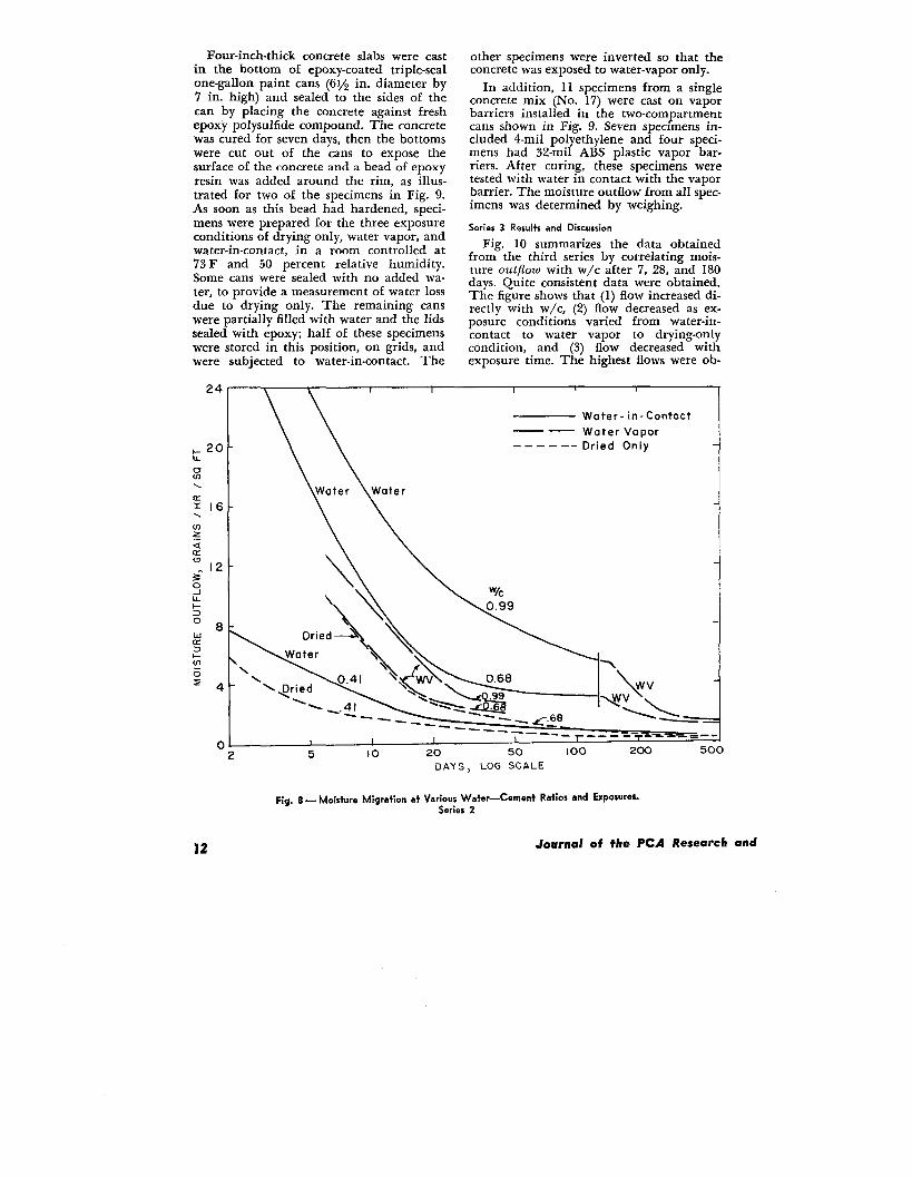
Four-inch-thick concrete slabs were castin the bottom of epoxy-coated triple-sealone-gallon paint cans (61/2 in. diameter by7 in. high) and sealed to the sides of thecan by placing the concrete against freshepoxy polysulfide compound. The concretewas cured for seven days, then the bottomswere cut out of the cans to expose thesurface of the concrete and a bead of epoxyresin was added around the rim, as illus-trated for two of the specimens in Fig. 9.As soon as this bead had hardened, speci-mens were prepared for the three exposureconditions of drying only, water vapor, andwater-in-contact, in a room controlled at73F and 50 percent relative humidity.Some cans were sealed with no added wa-ter, to provide a measurement of water lossdue to drying only. The remaining canswere partially filled with water and the lidssealed with epoxy; half of these specimenswere stored in this position, on grids, andwere subjected to water-in-contact. The
24
& 20u-0u)\a116\mzza
:1230i1-2
‘8
:2t-ln6
‘4
0
other specimens were inverted so that theconcrete was exposed to water-vapor only.
In addition, 11 specimens from a singleconcrete mix (No. 17) were cast on vaporbarriers installed in the two-compartmentcans shown in Fig. 9. Seven specimens in-cluded 4-roil polyethylene and four speci-mens had 32-roil ABS plastic vapor bar-riers. After curing, these specimens weretested with water in contact with the vaporbarrier. The moisture outflow from all spec-imens was determined by weighing.
Series 3 Results and Discussion
Fig. 10 summarizes the data obtainedfrom the third series by correlating mois-ture outflow with w/c after 7, 28, and 180days. Quite consistent data were obtained.The figure shows that (1) flow increased di-rectly with w/c, (2) flow decreased as ex-posure conditions varied from water-in-contact to water vapor to drying-onlycondition, and (3) flow decreased withexposure time. The highest flows were ob-
1 I 1
Water- in- Contact
—— Water Vapor
------ Dried Only
\
\\
\Qjerj\\
\.~_-..
--—— __t I I
5 10 20 50 100 200
DAYS, LOG SCALE
Fig. 8 — Moisture Migration at Various Water—Cement Ratios and Exposures.Series 2
Journal of the PCA
500
Research and

T Concrete Surface
Dried OnlyL Concrete surf~~el
Exposure : Woter Vopor Woter-in -No Woter Contact
Fig. 9 — Gallon Paint Cans Used for Series 3 Tests.
tained for high w/c concretes at early ageswhen the slab was in direct contact withwater. In addition, the data show that atlow w/c little or no difference in flow oc-curred at early ages regardless of the ex-posure condition.
Several individual relationships derivedfrom Fig. 10 (and Table 5) are illustratedin Figs.. 11, 12, 13, and 14. Fig. 11 comparesthe outflow of moisture from slabs madeat different w/c when exposed to water-in-contact. FIOW increased rapidly with in-creasing w/c, but diminished with age. Fig.12 shows similar data for specimens ex-posed to water vapor only. The same gen-eral relationships of higher flow withhigher w/c and decreasing flow with in-creasing duration of exposure are apparent.Although moisture outflow for the two ex-posure conditions (water and water vapor)
TABLE 4—MIX DATA AND PHYSICAL PRO PERTIE%SERIES 3 CONCRETES
was essentially the same at low w/c, therewas a great difference in ffow at high w/c.The moisture outflow due to drying only,shown in Fig. 13, is the rate at which themix water evaporated from the surfacewhen exposed to 50 percent relative humid-it y air. These outflows were only slightlydifferent from the outflows from companionspecimens exposed to water vapor at earlyages, but decreased to less than 50 percentafter 365 days exposure.’
A comparison of outflows for the threeexposure conditions at w/c of 0.40, 0.60and 0.80 are shown in Fig. 14. The severityof the exposure produced only small ab-solute differences at low w/c; the outflowwith water-in-contact was only 0.4 grains/hr/sq ft after one year exposure. High w/cconcretes, however, had wide differences inoutflow for the different exposure condi-
Celnent content cm?. St,.,Mix w/c unit w!, Air slump,No.
p,, .? Admixturelb/u yd b.ags/eu yd lb/c” ft content, y. in. 28 day,
4 0.41 681 7.2 I 49.0 1,7 4.5 7460 No..
16 0,43 545 5,8 140,2 6.6 4.4 50s0 AEA-3
15 0.44 5S8 6.13- 143.6 4.5 4.6 5740 AEA-4
13 0.44 57s 6.2 149,2 2,0 3,6 8020 tiydroxylakd
14 0.45
..arboxylk add
56o 6.o 144.6 3,5 5,0 6940 tign.wlf.nic acid
1 0.4B 567 6.0 147,3 1.6 5.0 6320 None
11 0.50 568 6.0 + I 47,9 2,7 4.9 5960 2% Bvtyl ,teerote
Jo 0.50 514 5.5 147.3 2.5 3.0 5850 Calcium chloride SO1.
17 0.50 455 4.9 1 3s,9 7,0 5,2 42S0
12
AEA-3
0.51 569 6.0 148.7 1.5 4.2 6670 270 Calcium chloride
2 0,56 4s7 4.9 147.4 2.0 2.0 5260 None
3 0.67 386 4.1 145,9 2.3 3.7 3350 None
6 0,69 303 3.2 144.8 4.s 2.5 2930 AEA-4
5 0.70 294 3.1 140.5 6.5 4.2 2510 AEA-3
7 0.84 304 3.2 146.2 2.2 1.6 2410 Calcium chl.ride SOI.
9 0,84 305 3.2 146,9 1.6 1.5 2200
8 0.89
2% Colci.m chloride
302 3.2 145,7 1.7 2.6 2060 2% B.iyl sle.ara!e
Development Laboratories May 1965 13

tions. After one year, substantial quantitiesof water were still passing through theslabs of 0.80 w/c, as indicated by flows of2.5, and 1.1 for water-in-contact and watervapor, respectively. Although the drying-only condition indicated high flow at earlyages, this reduced to 0.5 grains after oneyear.
Wk - GAL, / BAG
‘“~
12i-. t / A0..c 10x.
g7doy
aC8“
%“
3
:6~
ua24m5>
2 -
._- ——— ——— —— —————————0
0.40 0,50 0,60 0.70 080 0.90 I 00
‘lG B’i wEIGHT
Fig. 10— Correlation of Moiskme Migration with
Water-Cement Ratio, Type of Gposure, and Days
Su~ected to Sxposure.Series 3
I03
I7 14 28 60 90 !80 365
DAYS EXPOSED
Fig.I1— Moisture Migration with
Water in Contact.Series 3
(2
0
\
3 7 14 28 60 90 (W 365DAYS EXPOSED
Fig. 12 — Moisture Migration withWater Vapor in Contact.
Series 3
(21 , 3 ,, ,
DAYS EXPOSED
Fig. 13 — Moisture Migration Due
to Drying Only.Series 3
Fig. 14 — Moisture Migration at Various Water-Cement Ratios and Exposures.
Series 3
14 Journal of the PCA Research an

Fig. 15 provides a comparison betweenconcretes with and without admixtures.The numbers and letters above the plottedpoints indicate the concrete mixes de-scribed in Tables 2 and 4. Concretes with-out admixtures are (l), (2), (3), (4), and(L). Data from three concretes (L, K andM) from Series 2 are included with the17 concretes of Series 3. It is apparent thatall of the points lie close to the averagecurves, indicating that these admixtureshad no appreciable effect on moisture mi-gration when compared with plain con-cretes of the same w/c. This conclusion,based on the 90-day test results of Fig. 15,was found to apply at all ages.
In addition to the above tests, specimensfrom concrete mix No. 17 were cast in two-compartment paint cans fitted with vaporbarriers. Both 4-roil polyethylene film (7specimens) and 32-roil ABS plastic sheeting(4 specimens) were tested with water incontact with the vapor barrier as shownin Fig. 9. Fig. 16 compares outflow from
TASLE 6—MOISTURE OUTFLOW AND PERCENTSATURATION OF 0.50 W/C CONCRETE
AT AGE ONE YEAR
M.;.,.,e Degree ofoutflow, Sat.r#iOn,
Test Condition gr/hr/,q ft
Water i. c.”tact with concrete 0.73 81
Water v.pc.r i. contact with concrete 0.66 76
Water in contact with 4-roil polyethylene 0.45 53
Weter in c.ntact with 32-roil ABS plastic 0.32 51
Drying onlY—No wafer added f. CO. 0.29 50
these specimens with the outflows obtainedfrom specimens without vapor barriers. A1-though both vapor barriers reduced theoutflow for water-in-contact, the 4-roil filmwas less effective than the 32-roil sheeting.Neither vapor barrier, however, eliminatedentry of water into the concrete as indi-cated by both higher outflow from the slaband higher percent saturation at the endof the ‘test, is shown by Table 6.
TABLE 5—MOISTURE MIGRATION FOR CONCRETES OF SERIES 2 AND 3
Mc.kt.re Migration, gr.sins/hr/,q ft .1 W/C WIlwm %h.wn
O,lys ExposureW/C =0.40 0.50 0.60 0.70 0.00 0.90 1.00
3 w* 4.s 7.8 11.6 20.4 27.0 33.0 43,8
Wv 5.0 8.0 11,5 17.0 21.0D
24.4 27.2
5.2 8.o 11.4 16.3 19.2 21.2 22.s
7 w 2.9 4.7 7.7 11.8 16.4 21.5 27.0
Wv 3.0 4.8 6.7 8.4 9.s 11.0 12.4
D 3.1 4.6 6. I 7.6 9.0 10.2 11,5
14 w 1.8 3.0 5.0 8.1 11. I 14.4 18,2
Wv 1.8 2.9 3.9 4.8 5.6 6.3 6.8
D 1.9 2.8 3.7 4.6 5.0 5.5 6.0
28 w 1.2 1.9 3.3 5,3 7.5 9.9 11.8
Wv 1.1 1.8 2,9 3.0 3.4 3.6 3.8
D 1.1 I .7 2.3 2.6 2.s 3.0 3.2
60 w 0,8 1.3 2.2 3.4 4.7 6.1 7.4
Wv 0.8 1.2 1.6 2.0 2.2 2.4 2.5
0 0.7 1.1 1.3 1.5 1..5 1.7 1.8
90 w 0.7 1.1 1.9 2.9 3.8 5.0 6.o
Wv 0.7 1.0 I .4 1.7 1.8 1.9 2.1
D 0.5 0.8 1.0 1.1 1.2 1.3 1.4
1 so w 0.5 0.9 1.5 2.2 3.0 3.9 4.8
Wv 0.5 0.s 1.1 1.3 1,4 1.4 1.5
D 0.3 0.5 0.6 0.6 0.7 0.8 0.9
365 w 0.4 0.7 1.3 1.9 2.5 3.3 4.1
Wv 0.4 0.6 0.9 1.0 1.1 1.1 1.1
D 0.2 0.3 0.4 0.4 0.5 0.5 0.5
*w = W.ier.i.. contact.
WV= Waler voPor.D = Dried only.
levelopmenf Laboratories May 1965 15

6
y
tasm. K
15:.4 - k /
zM,. No’s
z–-w.ler-in-c.”,.d
%3
s-
2 y.. I ,3
0
;
.
01.d+c.ates cm.rete without .dmixt. re
o] L I040 0,50 0.60 070 0.s0 090 KY3
‘k BY WEIGHT
F;g. 15 — Comparhon of Concrefes With and
Wfhou+ Admixtures After 90 Days Exposure.
Series 2 and 3
SUMMARY AND CONCLUSIONS
The principal conclusions drawn fromthis study on moisture migration from 4-inch-thick concrete dabs are:
(1) Flow varies directly with the water-cement ratio of the concrete. The w/c ratiocontrols the flow but of course the valuesobtained vary with time exposed, type ofexposure (Fig. 10), and method of meas-urement (i.e. outflow or inflow).
(2) Moisture migration through goodquality concrete was less than 0.3 grains/hr/sq ft; but the flow through low qualityconcrete often exceeded 2.0 grains.
(3) The outflotu or rate of moisture lossfrom the surface of the same concretes, how-ever, is much higher at early ages — ap-proximately four times the above values at28 days, and ten times at seven days. Thisoutflow at early ages is the flow that con-tributes to the problems encountered uponinstallation of floor coverings.
(4) After extended exposure periods, ex-ceeding one year under the constant tern.perature and humidity conditions of thesetests, inflow and outflow will become equal;at that time stabilized moisture migrationthrough concrete is attained.
(5) On the basis of concretes of equalw/c, the admixtures used neither contrib.uted to, nor detracted from, the measuredflow to any appreciable degree (Fig. 15).
(6) A gravel capillary break betweenthe clay soil and concrete slab reduced theinflow by 10 to 25 percent (Figs. 3 and 4).
(7) Vapor barriers below concrete slabsnormally reduce moisture migration (Figs.3 and 16). However, moisture migrationmay be increased at early ages when seep-age of excess mix water to the subbase isretarded by the vapor barrier (Figs. 6 and7).
(8) Application of an impervious bar-rier (such as floor tile) on a partially driedconcrete surface reduced evaporation butincreased the moisture content of the con-crete when moisture was available belowthe slab. This occurred even when a vaporbarrier was used.
REFERENCES
1. “Slab-On-Ground Construction for Residences,” - National Research Council, Washington, D.C.,National Academy of Sciences – National Re- IWfrlicatio?c 596 (1958), 32 pages.search Council, Washington, D.C., Publication385 (1955), 50 pages.
4. “Design Criteria for Residential Slabs-On-
2. “Vapor Barrier Materials for Use with Slab-On-Ground: National Academy of Sciences — Na.
Ground Construction and as Ground Cover intional Research Council, Washington, D. C., Pub-
Crawl Spaces,” National Academy of Sciences —Iication 657 (1959), 73 pages.
National Research Council, Washington, D.C., 5. “Protection from Moisture for Slab-On-GroundPublication 445 (1956), 23 pages. Construction and Habitable Spaces Below
3. “Effectiveness of Concrete Admixtures in Con- Grade,” National Academy of Sciences - Pa-
trolling Transmission of Moisture Through tional Research Council, Washington, D. C.,
Slabs-on-Ground: National Academy of Sciences Publication 707 (1959), 67 pages.
16 Journal of the PCA Research am

MIX 17- ‘/c 0,50
Water-in-Contact
.— . Water Vapor
Water in Contact with—— —4-roil Polyethylene
_ __ Water in Contact with!32-niil Plastic
—- —-— Dried Only
\
———
——-n ---- ____
,A - --- --- . A-
Iuu <Uu Ouu f-fUu
DAYS
Fig. 16— Effect of Vapor Barriers.Series 3
6. Lund, C. E., “Moisture Migration and VaporPermeability of Concrete Storehouse Floors,”University of Minneaot3, Institute of Tech-nology, Minneapolis, Minnesota, U.S. Navy Con-tract NOy 73218, Summary Report (June 15,1955), 51 pages.
7. “Moisture Migration from the Ground,” Hous-ing and Home Finance Agency, Washington,D.C., Housing Research Paper No. 28 (April1954), 13 pages.
8. Kocataskin, F,, and Swenson, E. G., “Methodsfor Rating Concrete Waterproofing Materials;’ASTM Bdetin, pages 67-72 (ApriI 1958).
9. Powers, T. C., Copeland, L. E., Hayes, J. C.,and Mann, H. M., “Permeability of PortlandCement Paste,” Journal of the American Con-crete Institute (November 1954); Proceedings,51, 285-298 (1954-55); PCA Research Depart-ment BuUetin 53.
10. Griffin, D. F., and Henry, R. L., “IntegralSodium Chloride Effect on Strength, WaterVapor Transmission, and Ellloreacence of Con-crete,” Journal of the American Concrete In-stitute (December 1961); Proceedings, 58, 751-772 (1961).
PCA.R&D.Ser.1090-3
IJevefopmenf Lahorafories May 196517

Bulletins Published by the
Development Department
Research and Development Laboratories
of +he
Portland Cement Association
D1 _,,Influence of Soil Volume Change and Vegetation on Highway En.ghm%w” bYE. J. FELT,
Reprinted from Twent&Sfxth Annual HighwaV Conference of the University of Colorado,January, 1953, 52-76.
D2 —“Nature of Bond in Pre-Tensioned Prestressed Concrete,” by JACK R. JANNEY.Reprinted from Journal of the American Concrete Institute (May, 1954); Proceedings,50, 717-736 (1954) .
D2A—Discussion of the paper “Nature of Bond in Pre-Teneioned Prestressed Concrete,”by P. W. ABELES,K. HAJNAL-KONYI, N. W. HANSON and Author, JACK R. JANNEY.
Reprinted from Jou?vzat of the American Concrete Institute (December, Part 2, 1954);Proceedings, 50, 73S-1 to 736.11 (1954).
D3 —“Investigation of the Moisture-Volume Stability of Concrete Masonry Units,” byJOSEPH J. SHIDELER.
Published by Portland Cement Association, Research and Development Laboratories,Skokie, Illinois, March, 1955.
D4 —“A Method for Determining the Moisture Condition of Hardened Concrete inTerms of Relative Humidity: by CARL A. MENZEL.
Reprinted from Proceedings, American Society for Testing Materiats, 55, 1.26 (1955).
D5 —“Factors Influencing Physical Properties of Soil-Cement Mixtures,” by EARL J.FELT.
Reprinted from Highway Research Board BuUetin 10S, 13S-162 (1955).D6 —<’Concrete Stress Distribution in Ultimate Streneth Desien.” bv E. HoGNEaTAD.
D6A
N. W. HANaoN and D. MCHENRY.---
Reprinted from Journal of the American Concrete Institute (December, 1955): Proceed-ings, 52, 455-479 (1956).
(part of D6)—Discussion of the paper, “Concrete Stress Distribution in UltimateStrenMh Design,” by P. W. AaELES, A. J. ASRPOWN, A. L. L. BAKER, ULF BJUGGREN,HENR; J. COWAN, HOMER M. HADLEY, KONRAD HRUBAN, J. M. PRENTIS, E. ROSEN-BLUETH,G. M. SMITH, L. E. YOUNG, A. J. TAYLOR, and Authors, E. HOGNESTAD,If. W.HANSON. and D. MCHENRY.
Reprinted from Journal of the American Concrete Institute (December, Part 2, 1956);Proceedings. 52, 1305-1330 (1956).
D7 —“Ultimate Flexural Strength of Prestressed and Conventionally Reinforced Con-crete Beams,” by J. R. JANNEY, E. HOGNESTADand D. MCHENRY.
Reprinted from Journal of the American Concrete Institute (February, 1956); Proceed-ings, 52, 601-S20 (1956).
D8 —“Resurfacing and Patching Concrete Pavement with Bonded Concrete,” by EARLJ. FELT.
Reprinted from Proceedings of the Highwav Research Board, 35, 444-469 (1956).
D9 —“Review of Data on Effect of Speed in Mechanical Testing of Concrete,” by DouG-LAa MCHENRY and J. J. SRIDELER.
Reprinted from ASTM Special Technical Publication No. 185, 72-S2 (1956), AmericanSociety for Testing Materials.
D1O — “Laboratory Investigation of Rigid Frame Failure,” by R. C. ELRTNER and E.HOGNESTAD.
Reprinted from Journal of the American Concrete Institute (January, 1957); Proceed-ings, 53, 637-66S (1957).
Dll —“Tests to Evaluate Concrete Pavement Subbases,” by L. D. CmLDS, B. E. COLLEYand J. W. KAPERNICK.
Reprinted from the Journal of the Highwau Division, Proceedings of the AmericanSociety of Civil Engineers, Proc. Paper No. 1297. S3. 1-U Hw 3. JuIY. 1957.
D12 —“Ultimate Strength of Reinforced Concrete in American Design Practice,” byE. HOGNSaTAD. -
Reprinted from Proceedings of a Symposium on the Strength of Concrete Structures,London, May, 1956.

D13 —“Effect of Variations in Curing and Drying on the Physical Properties of Con-crete Masonry Units,” by WILLIAM H. KUENNING and C. C. CARLSON.
Published by Portland Cement Association, Research and Development Laboratories,Skokie, Illinois. December, 1956.
D14 —“Lightweight Aggregates for Concrete Masonry Units: by C. C. CARLSON.Reprinted from Journal of the A?ne~ican Concrete Institute (November, 1956); Pm.ceedings, 53, 491-50S (1956).
D15 —“Confirmation of Inelastic Stress Distribution in Concrete,” by EIVIND HOGNESTAD.Reprinted from the Journal of the Structural Division, Proceedings of the AmericanSociety of Civil Engineers, Proc. Paper 1189, S3, 1-17, ST 2, March 1957.
D16 —“Strength and Elastic Properties of Compacted Soil-Cement Mixtures,” by EARLJ. FELT and MELVIN S. ARRAMS.
Reprinted from ASTM Speciat Technical Publication No. 206, 152-176 (1957), AmericanSociety for Testing Materials.
D17 —“ Lightweight Aggregate Concrete for Structural Use,” by J. J. SHIOELER.Reprinted from Journal of the American Concrete Institute (October, 1957); Proceed-ings, 54, 299-328 (1957).
D18 —“ Stresses in Centrally Loaded Deep Beams,” by P. H. KAAR.Reprinted from Proceedings of the Societg for Experimental Stress Analysis, 15,No. 1, 77 (1957).
D19 —“Strength of Concrete Under Combined Tensile and Compressive Stresses,” byDOUGLASMCHENRY and JOSEPH KARNI.
Reprinted from Journal of the American Cancrete Institute (April. 1958); Proceed-ings, 54, s29-839 (1958).
D20 —“General Considerations of Cracking in Concrete Masonry Walls and Means forMinimizing It,” by CAKL A. MENZEL.
Published by Portland Cement Association, Research and Development Laboratories,Skokie, Illinois, September, 1958.
D21 —“Tests of Concrete Pavement Slabs on Gravel Subbases: by L. D. CHILDS andJ. W. KAPERNICK.
Reprinted from the Journal of the Highway Division, Proceedings of the AmericanSociety of Civil Engineers, Proc. Paper 1800, s4, 1-31, HW 3, October, 1958.
D22 —“Shear Strength of Lightweight Reinforced Concrete Beams:’ by J. A. HANSON.Reprinted from Journal of the American Concrete Institite (September, 1958): Pro-ceedings, 55, 387-403 (1958).
D23 —“ Performance of Subbases for Concrete Pavements Under Repetitive Loading,”by B. E. COLLEY and J. NOWLEN.
Reprinted from Highwav Research Board Bulletin 202, 32-58 (1958).
D24 —“Precast Concrete Girders Reinforced with High Strength Deformed Bars,” byJ. R. GASTON and EIVIND HOGNESTAD.
Reprinted from Journat of the American Concrete Institute (October, 195S); Proceed-ings, 55, 469-484 (1958).
D25 —“Concrete Beams and Columns with Bundled Reinforcement,” by N. W. HANSONand HANa REIFFENSTUHL.
Reprinted from the Journal of the Structural Division, Proceedings of the AmericanSociety of Civil Engineers, Proc. Paper 1818, 84, 1-23, ST 6, October, 1958.
J326 —“Review of Limit Design for Structural Concrete,” by C. W. Yu and EIVINDHOGNESTAD.
Reprinted from the Journal of the Structural Division, Proceedings of the AmericanSociety of Civil Engineers, Proc. Paper 1878, 84, 1-28, ST 8, December, 1958.
D27 —“ Laboratory Tests of Sealers for Sawed Joints,” by WXLLIAM KuENN~G.Reprinted from Highwau Research Board BuUetin 211, 1-12 (1959).
D28 —“FlexUral Bond Tests of Pre-Tensioned Prestressed Beams:’ by NORMAN W. HANaoNand PAUL H. KAAR.
Reprinted fmm Journal of the American Concrete Institute (January, 1959); Proceed-ings, 55, 783-802 (1959).
D29 —“Eff ects of Research on Modern American Structural Concrete Design,” by ENINDHOCNESTAD.
Reprinted from the Journal of the Structural Division, Proceedings of the American.Vocietg of Civil Engineem, Proc. Paper 2034, S5, 1-9, ST 5, May, 1959.
D30 —’ ‘Redistribution of Design Bending Moments in Reinforced Concrete ContinuousBeams: by ALAN HANSON MATTOCK.
Reprinted from the Proceedings of the Institution of Civil Engineers, Paper No. 6314,13, 3546, London, May, 1959.

D31 —“ Ultimate Strength Criteria for Reinforced Concrete,” by LADISLAV B. Kruz.Reprinted from the Journal of the Engineering Mechanics Division, Proceedings of theAmerican Societv of Civil Engineers, Proc. Paper 2095, 85, EM 3, 95-110, July, 1959.
D32 —“ Shear Strength and Elastic Properties of Soil-Cement Mixtures Under TriaxialLoading,” by GLENN G, BALMEU.
R&uted from Proceedings, American Society for Testing MateriaCs, 5s, 1187-1204
D33 —“ Facilities and Test Methods of PCA Structural Laboratory,” by EIVIND HOGNESTAD,N. W. HANSON, LADISLAVB. Karz and Omo A. KURVITS.
Reprinted from the Journal of the PCA Research and Development Laboratories, 1,No. 1, 12-20, 40-44 (1959); 1, No. 2, 30-37 (1959); 1, No. 3, 35-41 (1959).
D34 —“Precast-Prestressed Concrete Bridges 1. Pilot Tests of Continuous Girders, ” byPAUL H. KAAR, LADISLAVB. KRIZ and EIVIND HOGNESTAD.
Reprinted from the Journal of the PC!A Research and Development LabOTatOTieS, 2,No. 2, 21-37 (May, 1960).
D35 —“ Precast-Prestressed Concrete Bridges 2. Horizontal Shear Connections,” by NOR-MAN W. HANSON.
Reprinted from the Journal of the PCA Research and Development Laboratories, 2,No. 2, 38-58 (May, 1960).
D36 —“ Ultimate Strength of Over-Reinforced Beams,” by L. B. Kraz and S. L. LEE.Reprinted from Journal of the Engineering Mechanics Division, Proceedings of theAmerican Society of Civil Engineers, Proc. Paper 2502, 86, EM 3, 95-105, June, 1960.
D37 —“Laboratory and Field Tests of Granular Soil-Cement Mixtures for ‘Base Courses:by M. S. &KAMS.
Reprinted from ASTM Speciat Technical Pubticatfon, No. 254, 229-243 (1959), AmericanSociety for Testing Materials.
D38 —“ Limit Design for Structural Concrete,” by ALAN H. MATTOCK.Reprinted from the Journal of the PCA Research and Development Laboratories, 1,No. 2, 14-24 (May, 1959).
D39 —“Plastic Forms for Architectural Concrete,” by J. A. HANSON.Reprinted from Journal of the American Concrete Institute (May, 1960); Proceedings,56, 1137-1148 (19S0) .
D40 —“Manufacture and Use of Lightweight Aggregates for Structural Concrete,” byJ. J. SHXDELER.
Published by Portland Cement Association, Research and Development Laboratories,Skokie, Illinois, January, 1961.
D41 —“ Load Tests of Patterned Masonry Walls,” by R. O. HEDSTROXWReprinted from Journal of the American Concrete Institute (April, 1961); Proceedings,57, 1265-1286 (1961).
D42 —“ Early Soil-Cement Research and Development,” by MILES D. CATTON. Includingdiscussion by L. S. Blake, C. W. Britzuis, V. J. Brown, H. F. Clemmer, CarltonN. Conner, Ellis Danner, Pitt H. Jones, E. J. Kilcawley, D. J. Maclean, Rupert L.Springenschmid, W. R. Thomson, H. F. Winterkorn and K. B. Woods, andauthor’s closure.
Reprinted from the Journal of the Highway Division, Proceedings of the AmericanSocietv of Civit Engineers, Proc. Paper 1899, 85, 1-16. Hw L January. 1959; Discu=ion,85, ‘77-93 HW 3, September 1959; Closure, 86, 67-75, HW 1, March. 1960.
D43 —“ Precast-Prestressed Concrete Bridges 3. Further Tests of Continuous Girders,”by ALAN H. MATTOCK and PAUL H. KAAR.
Reprinted from the Journal of the PCA Research and Development Laboratories, 2,No. 3, 51-78 (September, 1960).
D44 —“ Repair of Concrete Pavements,” by EARL J. FELT.Reprinted from Journal of the American Concrete Institute (August, 1960): Proceed-ings, 57, 139-153 (1960).
D45 —“l?recast-Prestressed Concrete Bridges 4. Shear Tests of Continuous Girders,” byA. H. MATTOCK and P. H. KAAa.
Reprinted from the Journal of the PCA Research and Development Laboratories, 3,No. 1, 19-46 (January, 1961).
D46 —“ Precast-Prestre8sed Concrete Bridges 5. Creep and Shrinkage Studies,” by A. H.MA’LTOCK.
Reprinted from the Journal of the PCA Research and Development Laboratories, 3,No. 2, 32-S6 (May, 1961).

D47 —“Shearing Strength of Reinforced Concrete Slabs and Footings under ConcentratedLoads,” by JOHANNES MOE.
Published by Portland Cement Association, Research and Development Laboratories,Skokie, Illinois, April, 1961.
D48 —’TJltimate Strength of Non-Rectangular Structural Concrete Members;’ by A. H.MATTOCK and L. B. KRIZ,
Reprinted from Journal of theAmerican Concrete Institute (January, 1961); Proceed-ings, 57, 737-766 (1961 ).
D49 —“ Rectangular Concrete Stress Distribution in Ultimate Strength Design,” by A. H.MATTOCK,L. B. KRIZ and EIVIND HOGNEaTAD.
Reprinted from Journal of the American Concrete Institute (February, 1961); Proceed-ings, 57, 875-926 (1961 ).
D50 —“Tensile Strength and Diagonal Tension Resistance of Structural Lightweight Con-crete,” by J. A. HANSON.
Reprinted from Journal of the American Concrete Institute (.luly, 1961); Proceedings,5S, 1-39 (1961).
D51 —“ Precast-Prestressed Concrete Bridges 6. Tests of Half-Scale Highway BridgeContinuous over Two Spans,” by A. H. MATTOCK and P. H. KAAR.
Reprinted from Journal of the PCA Research and Development Laboratories, 3, No.3, 30-70 (September, 1961).
D52 —“High Strength Bars as Concrete Reinforcement, part 1. Introduction to a Seriesof Experimental Reports;’ by EIVIND HOGNESTAD.
Reprinted from Journal of the PCA Research and Development Laboratories, 3, No.3, 23-29 (September, 1961).
D53 —“High Strength Bars as Concrete Reinforcement, Part 2. Control of FlexuralCracking,” by EIVIND HOGNESTAD.
Reprinted from Journal of the PCA Research and Development Laboratories, 4, No.1, 46-63 (January, 1962).
D54 —“High Strength Bars as Concrete Reinforcement, Part 3. Tests of Full-Scale RoofGirder,” by J. R. GASTON and EMND HOGNESTAD.
Reprinted from Journal of the PCA Research and Development Laboratories, 4, No.2, 10-23 (May, 1962).
D55 —“ Connections in Precast Concrete Structures—Continuity in Double-T Floor Con-struction,” by FERDINANDS. ROSTASY.
Reprinted from Journal of the Prestressed Concrete Institute, 7, No. 4, 1S-4S (August,1962) .
D56 —“Structural Model Testing—Theory and Applications:’ by ALAN H. MATTOCK.Reprinted from Journal of the PCA Research and Development Laboratories, 4, No.3, 12-23 (September, 1962).
D57 —“Strength of Prestressed Concrete Pavements:’ by YUTAKA OSAWA.Reprinted from the Journal of the Structural Division, Proceedings of the AmericanSociety of Civil Engineers, Proc. Paper 3308, 88, S’T 5, 143-164, October, 1962.
D58 —“Control of Horizontal Cracking in the Ends of Pretensioned Prestressed ConcreteGirders,” by W. T. MARSHALL and ALAN H. MATTOCK.
F&#nted from Journal of the Prestressed Concrete Institute, 7, No. 5, 56-74 (October.
D59 —“High Strength Bars as Concrete Reinforcement, Part 4. Control of Cracking,” byP. H. KAAR and A. H. MATTOCK.
Reprinted from JoumaZ of the PCA Research1, 15-38 (January, 1963).
D60 —“Structural Model Testing—Compensation forCARPENTER.
Reprinted from Journal of the PCA Research1, 47.61 (January, 1863).
D61 —“ Strength of Structural Lightweight ConcreteHANSON.
Reprinted from Journal of the PCA Research1. 3946 (January. 1963).
and Development Laboratories, 5, No.
Time Effect in Plastics,” by J. E.
and Development Laboratories, 5, No.
Under Combined Stress,” by J. A.
and Development Laboratories, 5, No.
D62 —“’Optimum Steam Curing Procedure in Precasting Plants,” by J. A. HANSON.Reprinted from Journal of the American Concrete institute (January, 1963); Proceed-ings, 60, 75-100 (1963).
D62A—Discussion of the paper “Optimwn Steam Curing Procedure in Precasting Plan@”by E. G. W. BUSH, R. E. COPEMND,R. K. LZWIS, and Author, J. A. HANSON.
Reprinted from Journal of the American Concrete Institute (September, 1963); proceed-ings, 60, 12S7-1299 ( 1963).

D63 —“High Strength Bars as Concrete Reinforcement, Part 5. Lapped Splices in Con-centrically Loaded Columns,” by J. F. PFISTERand A. H. MATTOCK.
Reprinted from Journal of the PCA Research and Development Laboratories, 5, No. 2,27-4o (May, 1963).
.D64-’’Plant Drying and Carbonation of Concrete Block — NCMA-PCA CooperativeProgram,” by H. T. TOENNIZS and J. J. SKIDELER.
Reprinted from Journal of the Arne~ican Concrete Institute (May, 1963); Proceedings,60, 617-633 (1963) .
D65—’’Tests of Concrete Pavements on Crushed Stone Subbases,” by L. D. CHILDS andJ. W. KAPERNICK.
Reprinted from Journal of the Highway Division, Proceedings of the American Societyof Civii Engineers, Proc, Paper 3497, S9, HW 1, 57-SO, April, 1963.
D66—” Pressures at Foundation Soil Interfaces Under Loaded Concrete and Soil-CementHighway Slabs:’ by L. D. CHILDSand P. J. NUSSBAUM.
~l:m$ted from Proceedings, American Society for Testing and Materials, 62, 1243-1263
D67—’’Shear Strength of Slender Continuous Reinforced Concrete T-Beams,” by EIVINDHOGNESTAD,N. W. HANSON, D. D. MAGURAand M. A. MASS.
Reprinted from Journal of the PCA Research and Development Laboratories, 5, No. 3,22-35 (September, 1963).
D68-’’Structural Model Testing — A Profile Plotter;’ by N. W. HANSON and J. E. CAR-PENTRR.
Reprinted from Journal of the PCA Research and Development Laboratories, 5, No. 3,2-7 (September, 1963).
D69—” Carbonation Shrinkage of Concrete Masonry Units:’ by J. J. SHIVELER.Reprinted from Journal of the PCA Research and Development Laboratories, 5, No. 3,36-51 (September, 1963).
D70—” Laboratory Study of a 45-Foot Square Flat Plate Structure:’ by SIDNEY A.GURALNICK and ROBERTW. LAFRAUGH.
Reprinted from Jvumat of the American Concrete Institute (September, 1963);ProceedWgs 60, 1107-1165 (1963).
D71—” Influence of Concrete Strength on Strand Transfer Length,” by P. H. KAAR, R. W.LAFRAUCHand M. A. MASS.
~g;r from Journal of the Prestressed Concrete Institute, S, No. 5, 47-67 (October.
D72—’LStructural Applications of Pumped and Sprayed Concrete, ” by J. J. SHIDELERandALBERTLITVIN.
Published ,by Portland Cement Association, Research and Development Laboratories,Skokie, Illinois, January, 1964.
D73—’ ‘Connections in Precast Concrete Structures — Bearing Strength of Column Heads,”by L. B. KRIZ and C. H. RATHS.
Reprinted from Journal of the Prestressed Concrete Institute, S, No. 6, 45-75 (Decem-ber, 1963).
D74-’’High Strength Bars as Concrete Reinforcement, Part 6. Fatigue Tests,” by J. F.PFISTERand EIVIND HOGNESTAD.
Reprinted from Journal of the PCA Research and Development Laboratories, 6, No. 1,65-S4 (January, 1964).
D75-’’Prestress Loss as Affected by Type of Curing,” by J. A. HANSON.Reprinted from Journal of the Prestressed Concrete Institute, 9, No. 2, 69-93 (ApriL1964) .
D76—” Structural Model Testing — Techniques for Models of Plastic,” by J. E. CARFENTER,D. D. MAGURA,and N. W. HANSON.
Reprinted from Journal of the PCA Research and Development Laboratories. 6, No.2, 2647 (May, 1964).
D77—’ ‘Influence of Ties on the Behavior of Reinforced Concrete Columns,” by JAMZSF. PFISTER.
Reprinted from Journal of the American Concrete Institute (May,61, 521-537 (1964).
D78—” Shear Strength of Reinforced Structural Lightweight Aggregateby EIVINDHOGNESTAD,RICHARDC. ELSTNER,and J. A. HANSON.
Reprinted from Journal of the American Concrete Institute (June,61, 643-656 (1964).
1964); Proceedings
Concrete Slabs,”
1964); Proceedings

D79—” Connections in Precast Concrete Structures — Scarf Joints,” by J. R. GASTON andL. B. Karz.
Reprinted from Journal of the Prestressed Concrete Institute, 9, No. 3, 37-59 (June,1964).
D80—’ ‘Replacement of Lightweight Aggregate Fines with Natural Sand in StructuralConcrete,” by J. A. HANSON.
Reprinted frnm Journal of the American Concrete Institute (July, 1964); Proceedings61, 779-793 (1964)
D81—’’Tests of a Hyperbolic Paraboloid Reinforced Concrete Shell,” by C. W. YU andLADISLAVB. KRIZ.
Reprinted from Proceedings Wear.rICONFERENCE ON SHELLSTRUCTURES, Publication No.1187, National Academy of Sciences — National Research Council, 261-274 (1964).
D82—’’Analytical Investigation of Ribless Cylindrical Shells,” by LADISLAV B. KRIZ andSENG-LIP LEE.
Reprinted from Proceedings WORLD CONFERENCE ON SHELL STRUCTURES, Publication No.1187, National Academy of Sciences—National Research Council, 561-590 (1964).
D83—’’Techniques and Equipment for Field Testing of Pavements,” by W. J. NOWLEN.Reprinted from JOUTnUl of the PCA Research and Development Laboratories, 6, No. 3,43-52 (September, 1964).
D84-’ ‘High Strength Bars as Concrete Reinforcement, Part 7. Control of Cracking inT’-Beam Flanges;’ by P. H. KAAR and EIVINDHOGNESTAD.
Reprinted from Journal of the PCA Research and Devetop?nent Laboratories, 7, No. 1,42-53 (January, 1965).
D85—’’Crmnections in Precast Concrete Structures — Strength of Corbels,” by L. B. KRIZand C. H. RATES.
Reprinted from Jo!.Lrnat of the Prestressed Concrete Institute, 10, Nn. 1, 16-61 ( Feb-ruary, 1965).
D86—’’Tests of Concrete Pavement Slabs on Cement-Treated Subbases,” by L. D. CHILDS.Reprinted from Highway Research Record, Number 60, 39-58 (1964).
D87—’’Load Tests on Thin Pretensioned Pavement Slabs,”JANES.
by A. P. CHRISTENSEN and R. L.
Reprinted from Htglnvav Research Recwd, Number 60, 77-94 (1964).
D88—’’Load Tests on Post-Tensioned Pavement Slabs, ” by A. P. CHRISTENSEN.Reprinted from Highwav Research Record, Number 61L 95-115 (1964).
D89—’’Moisture Migration — Concrete Slab-On-Ground Construction,” by H. W. BREWER.Reprinted fmm Journal of the PCA Research and Development Laboratories, 7, No. 2,2-17 (May, 1965).
printed in U.S.A.