mohammad ali jinnah university, islamabad. shaper machine · pdf filemohammad ali jinnah...
TRANSCRIPT

Mohammad Ali Jinnah University, Islamabad.
Shaper Machine Project Report
Author: Zaheer ul hauqe

Shaper Machine | Zaheer ul hauqe
Page 1 of 16 Mohammad Ali Jinnah University, Islamabad.
Abstract
This is a student term project report regarding Shaper Machine and encloses the said machines’ theory,
analysis via various software, tables containing simulation results and graphical solution. The findings
and results of the machine along with the design are also discussed under separate headings.

Shaper Machine | Zaheer ul hauqe
Page 2 of 16 Mohammad Ali Jinnah University, Islamabad.
A thesis submitted in partial fulfilment of the requirements for the degree of Bachelor of Science in Mechanical
Engineering at the Mohammad Ali Jinnah University, Islamabad to Mr. Saeed regarding the term project named
Shaper Machine. Names and Registration no’s of our group are:
Zaheer ul Haque Me113008
Talal Ahmad Me113118
Dilber Khan Me113
Zohaib Ahmad Me113022
Shaper Machine | Zaheer ul hauqe
Page 3 of 16 Mohammad Ali Jinnah University, Islamabad.
TABLE OF CONTENTS Introduction .......................................................................................................................................................... 4
Theory ................................................................................................................................................................... 4
Crank-Slider Mechanism ................................................................................................................................... 4
Quick Return Mechanism ................................................................................................................................. 6
Methodology ........................................................................................................................................................ 7
Analysis ................................................................................................................................................................. 9
Conclusion ........................................................................................................................................................... 15
Bibliography ........................................................................................................................................................ 16
Shaper Machine | Zaheer ul hauqe
Page 4 of 16 Mohammad Ali Jinnah University, Islamabad.
SHAPER MACHINE
INTRODUCTION Shaper Machine is one of the simplest and important machines of the industry. It is a type of machine tool
that uses linear relative motion between the workpiece and a single-point cutting tool to machine a linear
tool path. A shaper is analogous to a planer, but smaller, and with the cutter riding a ram that moves
above a stationary workpiece, rather than the entire work piece moving beneath the cutter. The ram is
moved back and forth typically by a crank (Flywheel) and this mechanism works on the basic principle of
quick return.
Roe (1916) credits James Nasmyth with the invention of the shaper in 1836. Shapers were very common
in industrial production from the mid-19th century through the mid-20th.1
We selected this machine as our term project because of its simplicity and ease of fabrication. Every
theory that this machine involves was the basics we studied in our text book2, so along the partial
fulfillment of the course, it was also intended to strengthen the concepts and get a hands-on experience
on the practical part of Mechanical engineering.
THEORY The shaper machine involves two theoretical concepts of Machine designing i.e. crank-slider mechanism and
quick return.
Crank-Slider Mechanism
Crank-Slider mechanism is an arrangement of mechanical parts designed to convert straight-line motion
to rotary motion, as in a reciprocating piston engine, or to convert rotary motion to straight-line motion,
as in a reciprocating piston pump.
1 http://en.wikipedia.org/wiki/Shaper 2 Design Of Machinery by Robert L. Norton, 3rd Edition.
Shaper Machine | Zaheer ul hauqe
Page 5 of 16 Mohammad Ali Jinnah University, Islamabad.
3
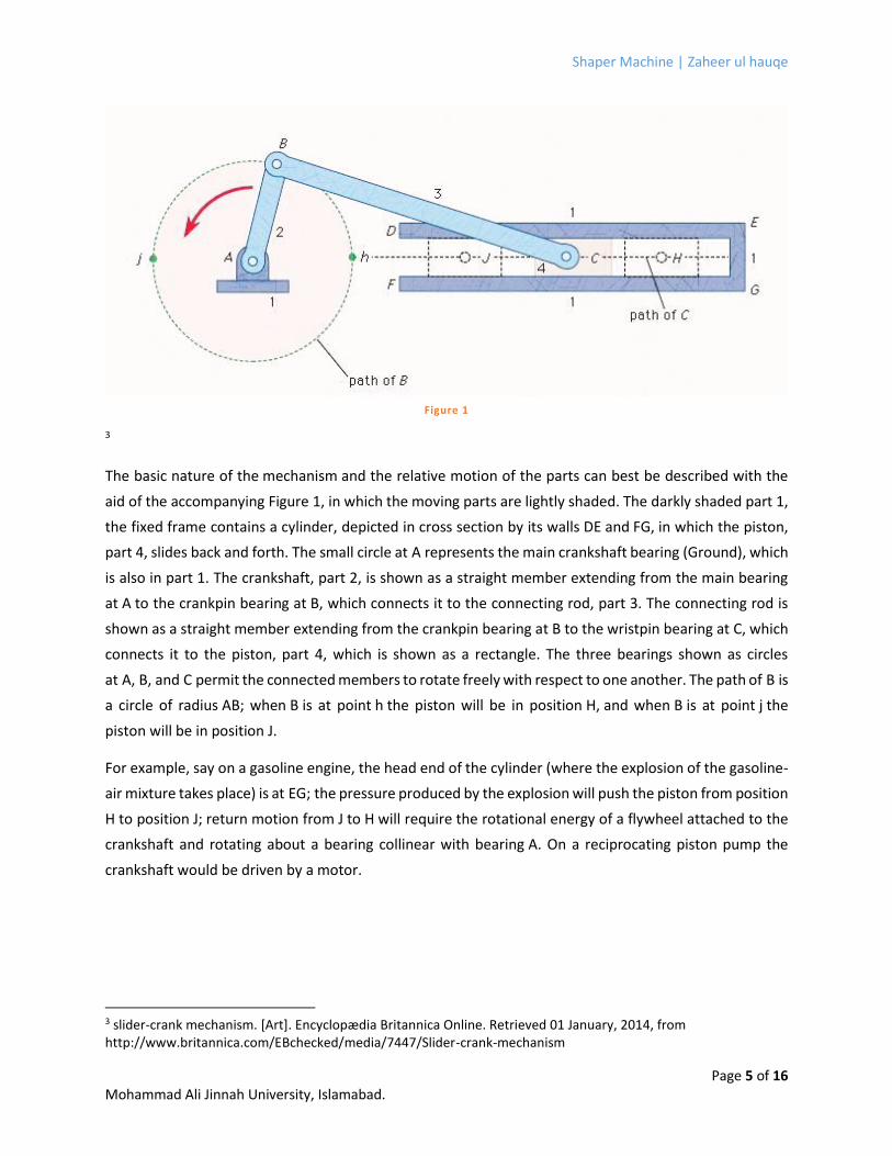
The basic nature of the mechanism and the relative motion of the parts can best be described with the
aid of the accompanying Figure 1, in which the moving parts are lightly shaded. The darkly shaded part 1,
the fixed frame contains a cylinder, depicted in cross section by its walls DE and FG, in which the piston,
part 4, slides back and forth. The small circle at A represents the main crankshaft bearing (Ground), which
is also in part 1. The crankshaft, part 2, is shown as a straight member extending from the main bearing
at A to the crankpin bearing at B, which connects it to the connecting rod, part 3. The connecting rod is
shown as a straight member extending from the crankpin bearing at B to the wristpin bearing at C, which
connects it to the piston, part 4, which is shown as a rectangle. The three bearings shown as circles
at A, B, and C permit the connected members to rotate freely with respect to one another. The path of B is
a circle of radius AB; when B is at point h the piston will be in position H, and when B is at point j the
piston will be in position J.
For example, say on a gasoline engine, the head end of the cylinder (where the explosion of the gasoline-
air mixture takes place) is at EG; the pressure produced by the explosion will push the piston from position
H to position J; return motion from J to H will require the rotational energy of a flywheel attached to the
crankshaft and rotating about a bearing collinear with bearing A. On a reciprocating piston pump the
crankshaft would be driven by a motor.
3 slider-crank mechanism. [Art]. Encyclopædia Britannica Online. Retrieved 01 January, 2014, from http://www.britannica.com/EBchecked/media/7447/Slider-crank-mechanism
Figure 1
Shaper Machine | Zaheer ul hauqe
Page 6 of 16 Mohammad Ali Jinnah University, Islamabad.
Quick Return Mechanism
It is a reciprocating motion, in which the return is made more rapidly than the cutting stroke, so as to
reduce the idling time. The name does not actually mean the ‘return’ being faster. Provided the crank
movement is reversed4, it can also become ‘Quick Forward mechanism’.
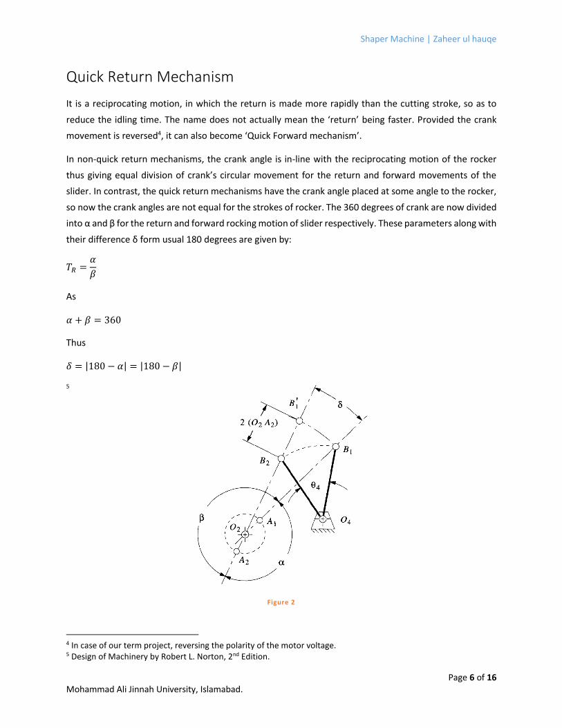
In non-quick return mechanisms, the crank angle is in-line with the reciprocating motion of the rocker
thus giving equal division of crank’s circular movement for the return and forward movements of the
slider. In contrast, the quick return mechanisms have the crank angle placed at some angle to the rocker,
so now the crank angles are not equal for the strokes of rocker. The 360 degrees of crank are now divided
into α and β for the return and forward rocking motion of slider respectively. These parameters along with
their difference δ form usual 180 degrees are given by:
𝑇𝑅 =𝛼
𝛽
As
𝛼 + 𝛽 = 360
Thus
𝛿 = |180 − 𝛼| = |180 − 𝛽|
5
4 In case of our term project, reversing the polarity of the motor voltage. 5 Design of Machinery by Robert L. Norton, 2nd Edition.
Figure 2
Shaper Machine | Zaheer ul hauqe
Page 7 of 16 Mohammad Ali Jinnah University, Islamabad.
METHODOLOGY The shaper machine term project was chosen on the basis of its simplicity. The group indulged in various
discussions and meetings with the course instructor. After declining 2 other designs the final design (Figure 3,
page 5) was selected and we sat upon calculating every minor detail. Drawings were made and simulations
were run on several software such as MATLAB, FOURBAR SLIDER, Working Model and Microsoft Excel.
We chose wood as our primary work material as it is easier to work on and is easier on the pocket. We did
not spend time on choosing the particular type as it wasn’t necessary on a project of such small scale. For the
driving motor we decided to get it from a worn out microwave oven as it would have low RPM yet sufficient
torque.
After the drawing board session and upon finalizing we contacted local carpenters and sat up a meeting. We
chose the professionals as we would couldn’t have made it with the finishing and in less time as the
carpenter could have.
The biggest problem that we faced was making the craftsman understand what we really wanted him to
make as he couldn’t speak in technical terms and we couldn’t in layman’s language. After a tiring session of
talks and teaching him the drawings, he finally understood.
We had to change several parameters in his workshop as designing something in a room is very different
form making it in a workshop. The availability of machines and proper tools plus the assumptions that we
made in the designing process were causing problems in the real world. This exercise also made us realize the
practical implementation is different from designing and one should keep the technical aspects of the
workshop facility, such as tools available there, in mind for the smooth flow of the process.
The design parameters of the project in final form are:

Shaper Machine | Zaheer ul hauqe
Page 8 of 16 Mohammad Ali Jinnah University, Islamabad.
6
Figure 3
6 Drawn By the Author via AutoCAD 2013 (Mechanical suite).

Shaper Machine | Zaheer ul hauqe
Page 9 of 16 Mohammad Ali Jinnah University, Islamabad.
ANALYSIS We simulated the machine on several software and their findings are given below.
7 Figure 4
8Figure 5
7 Working Model Simulation Snapshot. 8 Four Bar Slider Simulation Snapshot.
Figure 4
Figure 5

Shaper Machine | Zaheer ul hauqe
Page 10 of 16 Mohammad Ali Jinnah University, Islamabad.
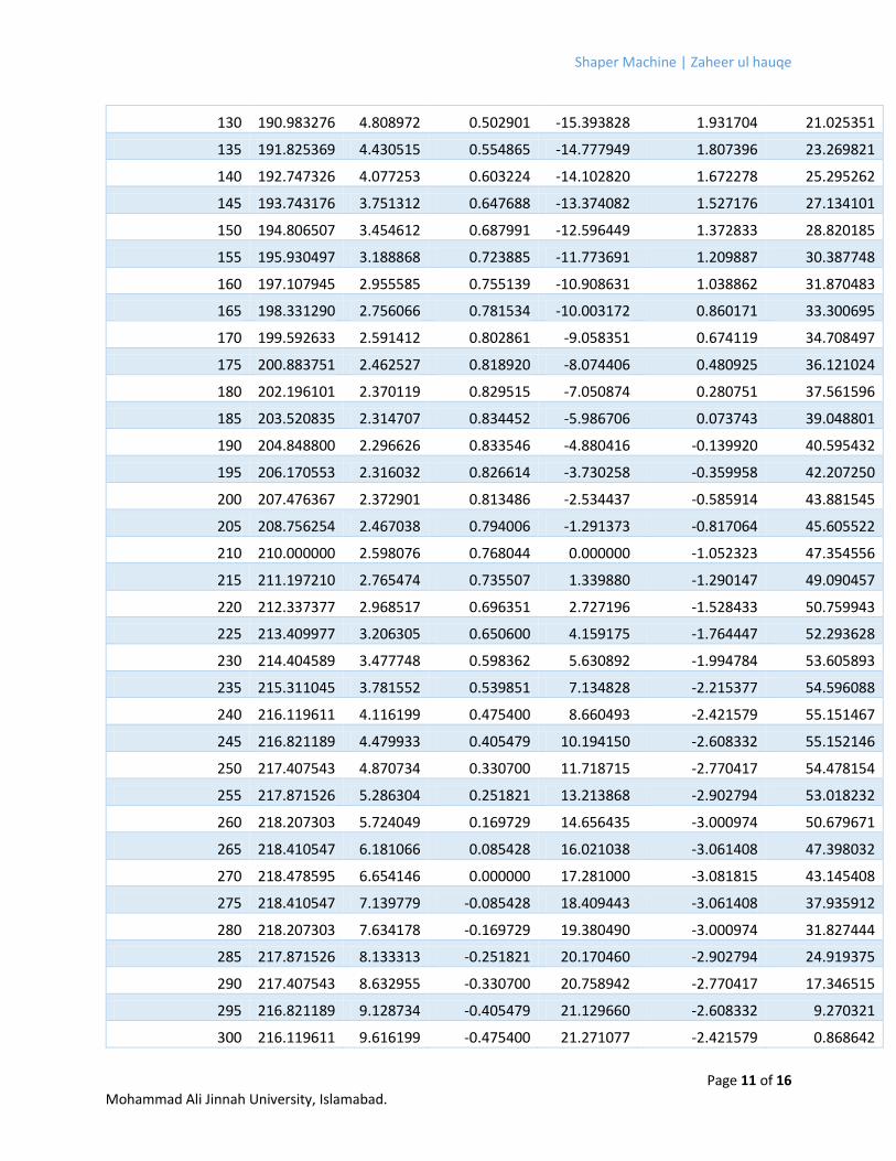
We used Microsoft Excel 2013 to get analytical solutions. The following table represents position, velocity,
and acceleration analysis. Here Crank Angle represents the position of crank for every degree with respect
to X-axis of global coordinate system placed at its center, and the data is in degrees. θ3 is the angle of
coupler link with respect to x-axis of local coordinate system placed at coupler-slider pin joint and this
data is also in degrees. d is the position of slider from global coordinate system and is in centimeters. ω3
is the velocity of coupler with respect to global coordinate system and is in Radians per Seconds. d' is the
slider’s velocity with respect to global coordinate system and is in centimeter per second. α3 is coupler’s
acceleration in Radians per Second square and is also with respect to global coordinate system. d'' is
slider’s acceleration with respect to global coordinate system and is in Radians per Second square.
Crank Angle (Deg) θ3 (Deg) d (cm) ω3 (Rad/sec) d' (cm/sec) α3 (Rad/ Sec^2) d'' (cm/sec^2)
5 200.883751 13.420669 -0.818920 5.062129 0.480925 -72.031500
10 199.592633 13.424298 -0.802861 3.056722 0.674119 -72.207795
15 198.331290 13.381250 -0.781534 1.057868 0.860171 -71.565669
20 197.107945 13.292203 -0.755139 -0.912269 1.038862 -70.147856
25 195.930497 13.158253 -0.723885 -2.832841 1.209887 -68.006145
30 194.806507 12.980892 -0.687991 -4.684551 1.372833 -65.200425
35 193.743176 12.761984 -0.647688 -6.449867 1.527176 -61.797672
40 192.747326 12.503742 -0.603224 -8.113205 1.672278 -57.870850
45 191.825369 12.208690 -0.554865 -9.661076 1.807396 -53.497685
50 190.983276 11.879636 -0.502901 -11.082200 1.931704 -48.759303
55 190.226540 11.519635 -0.447644 -12.367580 2.044315 -43.738733
60 189.560135 11.131951 -0.389431 -13.510537 2.144315 -38.519294
65 188.988480 10.720019 -0.328625 -14.506686 2.230798 -33.182891
70 188.515394 10.287408 -0.265615 -15.353882 2.302908 -27.808299
75 188.144064 9.837782 -0.200810 -16.052102 2.359875 -22.469466
80 187.877004 9.374864 -0.134640 -16.603293 2.401057 -17.233940
85 187.716035 8.902395 -0.067551 -17.011173 2.425968 -12.161477
90 187.662256 8.424106 0.000000 -17.281000 2.434305 -7.302916
95 187.716035 7.943682 0.067551 -17.419308 2.425968 -2.699358
100 187.877004 7.464734 0.134640 -17.433633 2.401057 1.618287
105 188.144064 6.990773 0.200810 -17.332227 2.359875 5.629391
110 188.515394 6.525186 0.265615 -17.123774 2.302908 9.323339
115 188.988480 6.071218 0.328625 -16.817123 2.230798 12.698934
120 189.560135 5.631951 0.389431 -16.421033 2.144315 15.763531
125 190.226540 5.210294 0.447644 -15.943953 2.044315 18.531964
Shaper Machine | Zaheer ul hauqe
Page 11 of 16 Mohammad Ali Jinnah University, Islamabad.
130 190.983276 4.808972 0.502901 -15.393828 1.931704 21.025351
135 191.825369 4.430515 0.554865 -14.777949 1.807396 23.269821
140 192.747326 4.077253 0.603224 -14.102820 1.672278 25.295262
145 193.743176 3.751312 0.647688 -13.374082 1.527176 27.134101
150 194.806507 3.454612 0.687991 -12.596449 1.372833 28.820185
155 195.930497 3.188868 0.723885 -11.773691 1.209887 30.387748
160 197.107945 2.955585 0.755139 -10.908631 1.038862 31.870483
165 198.331290 2.756066 0.781534 -10.003172 0.860171 33.300695
170 199.592633 2.591412 0.802861 -9.058351 0.674119 34.708497
175 200.883751 2.462527 0.818920 -8.074406 0.480925 36.121024
180 202.196101 2.370119 0.829515 -7.050874 0.280751 37.561596
185 203.520835 2.314707 0.834452 -5.986706 0.073743 39.048801
190 204.848800 2.296626 0.833546 -4.880416 -0.139920 40.595432
195 206.170553 2.316032 0.826614 -3.730258 -0.359958 42.207250
200 207.476367 2.372901 0.813486 -2.534437 -0.585914 43.881545
205 208.756254 2.467038 0.794006 -1.291373 -0.817064 45.605522
210 210.000000 2.598076 0.768044 0.000000 -1.052323 47.354556
215 211.197210 2.765474 0.735507 1.339880 -1.290147 49.090457
220 212.337377 2.968517 0.696351 2.727196 -1.528433 50.759943
225 213.409977 3.206305 0.650600 4.159175 -1.764447 52.293628
230 214.404589 3.477748 0.598362 5.630892 -1.994784 53.605893
235 215.311045 3.781552 0.539851 7.134828 -2.215377 54.596088
240 216.119611 4.116199 0.475400 8.660493 -2.421579 55.151467
245 216.821189 4.479933 0.405479 10.194150 -2.608332 55.152146
250 217.407543 4.870734 0.330700 11.718715 -2.770417 54.478154
255 217.871526 5.286304 0.251821 13.213868 -2.902794 53.018232
260 218.207303 5.724049 0.169729 14.656435 -3.000974 50.679671
265 218.410547 6.181066 0.085428 16.021038 -3.061408 47.398032
270 218.478595 6.654146 0.000000 17.281000 -3.081815 43.145408
275 218.410547 7.139779 -0.085428 18.409443 -3.061408 37.935912
280 218.207303 7.634178 -0.169729 19.380490 -3.000974 31.827444
285 217.871526 8.133313 -0.251821 20.170460 -2.902794 24.919375
290 217.407543 8.632955 -0.330700 20.758942 -2.770417 17.346515
295 216.821189 9.128734 -0.405479 21.129660 -2.608332 9.270321
300 216.119611 9.616199 -0.475400 21.271077 -2.421579 0.868642
Shaper Machine | Zaheer ul hauqe
Page 12 of 16 Mohammad Ali Jinnah University, Islamabad.
305 215.311045 10.090893 -0.539851 21.176705 -2.215377 -7.674609
310 214.404589 10.548412 -0.598362 20.845136 -1.994784 -16.178761
315 213.409977 10.984479 -0.650600 20.279849 -1.764447 -24.473878
320 212.337377 11.395006 -0.696351 19.488830 -1.528433 -32.406168
325 211.197210 11.776147 -0.735507 18.484069 -1.290147 -39.841316
330 210.000000 12.124356 -0.768044 17.281000 -1.052323 -46.666054
335 208.756254 12.436424 -0.794006 15.897906 -0.817064 -52.788371
340 207.476367 12.709520 -0.813486 14.355338 -0.585914 -58.136794
345 206.170553 12.941216 -0.826614 12.675562 -0.359958 -62.659114
350 204.848800 13.129512 -0.833546 10.882045 -0.139920 -66.320860
355 203.520835 13.272848 -0.834452 8.998983 0.073743 -69.103723
360 202.196101 13.370119 -0.829515 7.050874 0.280751 -71.004053
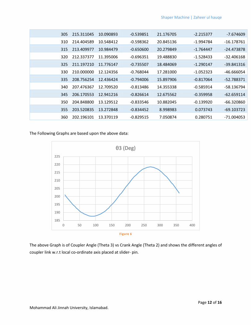
The Following Graphs are based upon the above data:
The above Graph is of Coupler Angle (Theta 3) vs Crank Angle (Theta 2) and shows the different angles of
coupler link w.r.t local co-ordinate axis placed at slider- pin.
185
190
195
200
205
210
215
220
225
0 50 100 150 200 250 300 350 400
θ3 (Deg)
Figure 6

Shaper Machine | Zaheer ul hauqe
Page 13 of 16 Mohammad Ali Jinnah University, Islamabad.
This one is a simple representation of Slider Position at various crank angles. It’s a simple fall with the
maximum distance being covered at 180 degrees and then it rises back to its position in the same fashion
because of the constant velocity of the motor.
ω3 is the coupler links velocity and has its rise and fall in a similar fashion as that of crank’s angle.
0
2
4
6
8
10
12
14
16
0 50 100 150 200 250 300 350 400
d (cm)
-1.00
-0.80
-0.60
-0.40
-0.20
0.00
0.20
0.40
0.60
0.80
1.00
0 50 100 150 200 250 300 350 400
ω3 (Rad/sec)
Figure 7
Figure 8
Shaper Machine | Zaheer ul hauqe
Page 14 of 16 Mohammad Ali Jinnah University, Islamabad.
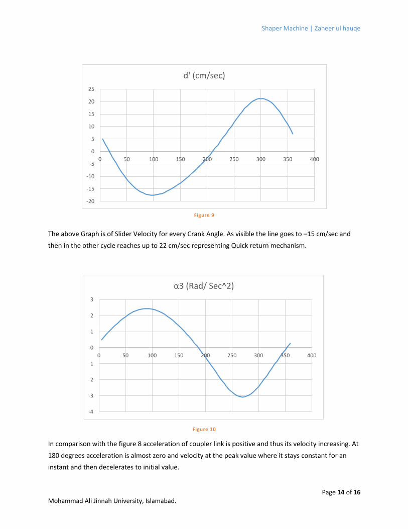
The above Graph is of Slider Velocity for every Crank Angle. As visible the line goes to –15 cm/sec and
then in the other cycle reaches up to 22 cm/sec representing Quick return mechanism.
In comparison with the figure 8 acceleration of coupler link is positive and thus its velocity increasing. At
180 degrees acceleration is almost zero and velocity at the peak value where it stays constant for an
instant and then decelerates to initial value.
-20
-15
-10
-5
0
5
10
15
20
25
0 50 100 150 200 250 300 350 400
d' (cm/sec)
-4
-3
-2
-1
0
1
2
3
0 50 100 150 200 250 300 350 400
α3 (Rad/ Sec^2)
Figure 9
Figure 10

Shaper Machine | Zaheer ul hauqe
Page 15 of 16 Mohammad Ali Jinnah University, Islamabad.
This Graph is of Slider Acceleration for various crank angles. Initially there is negative acceleration but is
increasing as the rocker is returning but the forward stroke gives the hike that can be seen here.
CONCLUSION The shaper is an amazing yet simple machine. Combining two textbook concepts has created a very
simple easy to use machine which use cannot be denied and is important for the smooth flow of the
industry.
This project has given us the practical experience of engineering and has taught us valuable lessons.
Theory and practical implementation are two very different things yet they cannot be separated and
none can survive without the other.
During this project we faced many setbacks but as determination is a vital quality to sustain success, we
managed and completed the task within the given time. Although a lot can be improved and a lot can be
thought over. From my point of view it still lacks precision and finishing which would greatly reduce the
friction and in turn increase the torque output. The increase in RPM would also elevate the efficiency
level and a flywheel can make the process smoother.
Yet it was a great success for me and my group, we really worked hard and put our hearts into it. I think
we have achieved more than we imagined and that gives me satisfaction and the hope to strive harder,
the next time.
-80
-60
-40
-20
0
20
40
60
80
0 50 100 150 200 250 300 350 400
d'' (cm/sec^2)
Figure 11
Shaper Machine | Zaheer ul hauqe
Page 16 of 16 Mohammad Ali Jinnah University, Islamabad.
BIBLIOGRAPHY
http://en.wikipedia.org/wiki/Shaper
www.technologystudent.com/equip1/shape1.html
http://www.merriam-webster.com/dictionary/quick%20return
http://www.wisc-online.com/ViewObject.aspx?ID=ENG20704
http://www.robives.com/mechanisms/quickreturn#.Usk5lfQW1eU
http://www.robives.com/mechanisms/crankslider
http://www.softintegration.com/chhtml/toolkit/mechanism/crankslider/
http://ditogear.com/tag/crankslider/
Design of Machinery by Robert L. Norton, 2nd Edition.
Design Of Machinery by Robert L. Norton, 3rd Edition.
slider-crank mechanism. [Art]. Encyclopædia Britannica Online. Retrieved 01 January, 2014, from
http://www.britannica.com/EBchecked/media/7447/Slider-crank-mechanism