module i: force system - · pdf fileis safe when p = 5kn. ... the beam ab has a negligible...
TRANSCRIPT
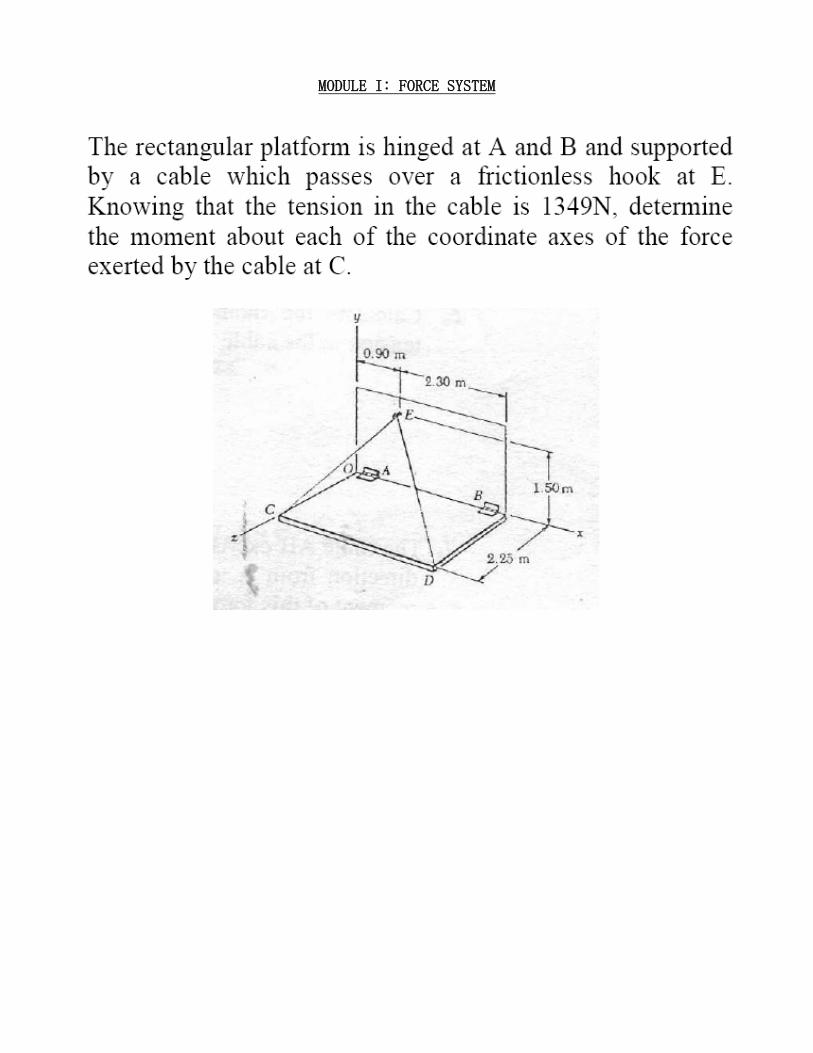
MODULE I: FORCE SYSTEM

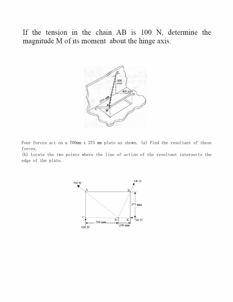
Four forces act on a 700mm x 375 mm plate as shown. (a) Find the resultant of these
forces.
(b) Locate the two points where the line of action of the resultant intersects the
edge of the plate.

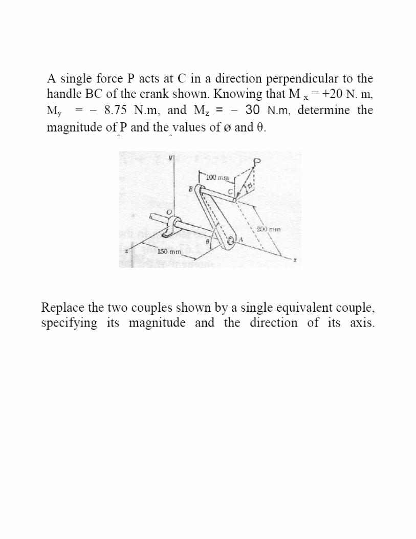
A rectangular block is acted upon by the three forces, which are directed along its
edges. Replace these forces by an equivalent force system at O and determine the
magnitude and the direction of the resultant force R. (MO = 4i + 5.5j - 6k Nm)
MODULE II: EQUILIBRIUM
1. As an airplane’s brakes are applied,
the nose wheel exerts two forces on
the end of the landing gear as shown.
Determine the x and y components of
reaction at the pin C and the force in
strut AB.

2. Three loads are applied to a light beam supported by cables attached at B and D knowing that the maximum allowable tension in each cable is 12KN and neglecting
the weight of the beam, determine the range of values of Q for which the loading
is safe when P = 5KN.
(1.5 kN ≤Q ≤9 kN)
3. The bent rod ABC is hinged to a
vertical wall by means of two brackets
and bears at C against another
vertical wall. Upper bracket fits in a
groove in the rod to prevent the rod
from sliding down. Neglecting

friction, determine the reaction at C when a
150N load is applied at D as shown. (RC = 45
N)
A sign is subjected to a wind loading that exerts
horizontal forces of 1340N on joints B and C of
one of the side supporting trusses. Determine the
force in members BC, CD, DB and DE of the truss
and state whether the members are in tension or
compression.

Determine by the method of sections the axial
forces is each of the bars IH, GH and CF of the
plane truss shown in the figure.
For the frame and loading shown, determine the
components of all forces acting on member ABD.

The tool shown is used to crimp terminals onto electric wires. Knowing that P= 135
N, determine the magnitude of the crimping forces which will be exerted on the
terminal.

MODULE III: FRICTION
The co-efficient of friction are as follows: 0.25 at the floor, 0.30 at the wall, and
0.20 between the blocks. Find the minimum value of force P applied to the lower
block that will hold the system in equilibrium.
A car is stopped with its front wheels resting against a curb when its driver starts the
engine and tries to drive over the curb. If the radius of the wheels is 280 mm, µ=0.85
between the tyres and the pavement, and 60% of the weight of the car is distributed over its
front wheels and 40% over its rear wheels, determine the largest curb height h that car can
negotiate, assuming (a) front-wheel drive, (b) rear wheel drive. ((a) h = 0.067 m, (b) h =
0.036 m)
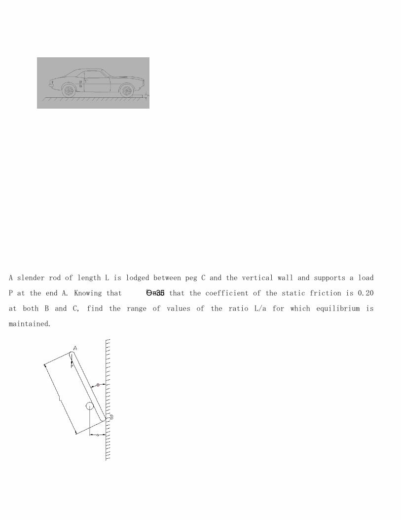
A slender rod of length L is lodged between peg C and the vertical wall and supports a load
P at the end A. Knowing that Ɵ=350 and that the coefficient of the static friction is 0.20
at both B and C, find the range of values of the ratio L/a for which equilibrium is
maintained.
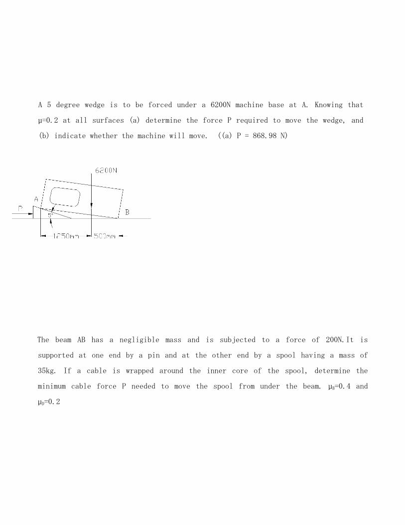
A 5 degree wedge is to be forced under a 6200N machine base at A. Knowing that
µ=0.2 at all surfaces (a) determine the force P required to move the wedge, and
(b) indicate whether the machine will move. ((a) P = 868.98 N)
The beam AB has a negligible mass and is subjected to a force of 200N.It is
supported at one end by a pin and at the other end by a spool having a mass of
35kg. If a cable is wrapped around the inner core of the spool, determine the
minimum cable force P needed to move the spool from under the beam. µB=0.4 and
µD=0.2
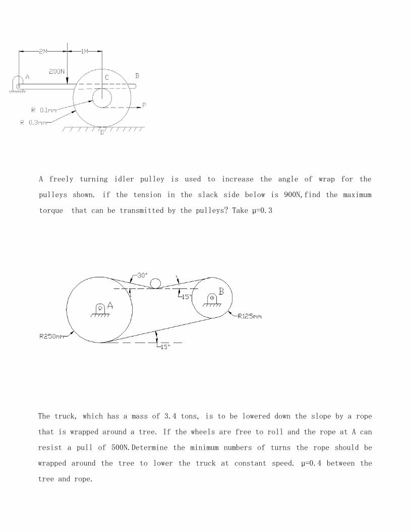
A freely turning idler pulley is used to increase the angle of wrap for the
pulleys shown. if the tension in the slack side below is 900N,find the maximum
torque that can be transmitted by the pulleys? Take µ=0.3
The truck, which has a mass of 3.4 tons, is to be lowered down the slope by a rope
that is wrapped around a tree. If the wheels are free to roll and the rope at A can
resist a pull of 500N.Determine the minimum numbers of turns the rope should be
wrapped around the tree to lower the truck at constant speed. µ=0.4 between the
tree and rope.

MODULE IV: PROPERTIES OF CURVES AND SURFACES
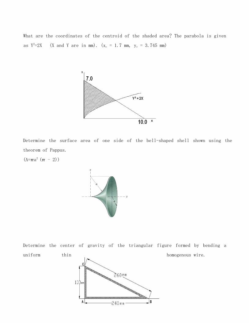
What are the coordinates of the centroid of the shaded area? The parabola is given
as Y2=2X (X and Y are in mm). (xc = 1.7 mm, yc = 3.745 mm)
Determine the surface area of one side of the bell-shaped shell shown using the
theorem of Pappus.
(A=a2 ( - 2))
Determine the center of gravity of the triangular figure formed by bending a
uniform thin homogenous wire.
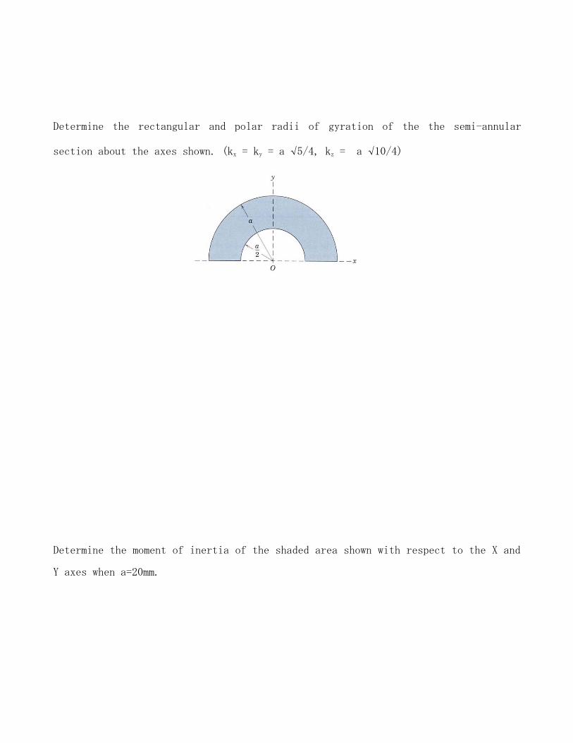
Determine the rectangular and polar radii of gyration of the the semi-annular
section about the axes shown. (kx = ky = a √5/4, kz = a √10/4)
Determine the moment of inertia of the shaded area shown with respect to the X and
Y axes when a=20mm.
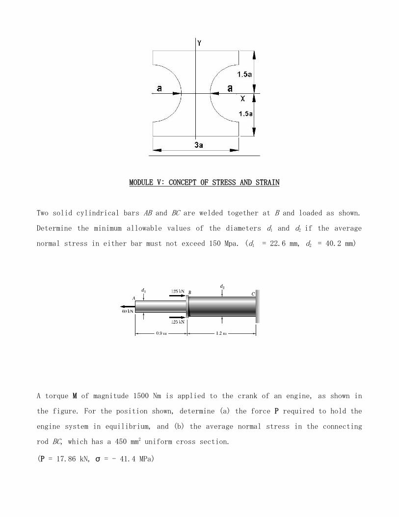
MODULE V: CONCEPT OF STRESS AND STRAIN
Two solid cylindrical bars AB and BC are welded together at B and loaded as shown.
Determine the minimum allowable values of the diameters d1 and d2 if the average
normal stress in either bar must not exceed 150 Mpa. (d1 = 22.6 mm, d2 = 40.2 mm)
A torque M of magnitude 1500 Nm is applied to the crank of an engine, as shown in
the figure. For the position shown, determine (a) the force P required to hold the
engine system in equilibrium, and (b) the average normal stress in the connecting
rod BC, which has a 450 mm2 uniform cross section.
(P = 17.86 kN, σ = - 41.4 MPa)
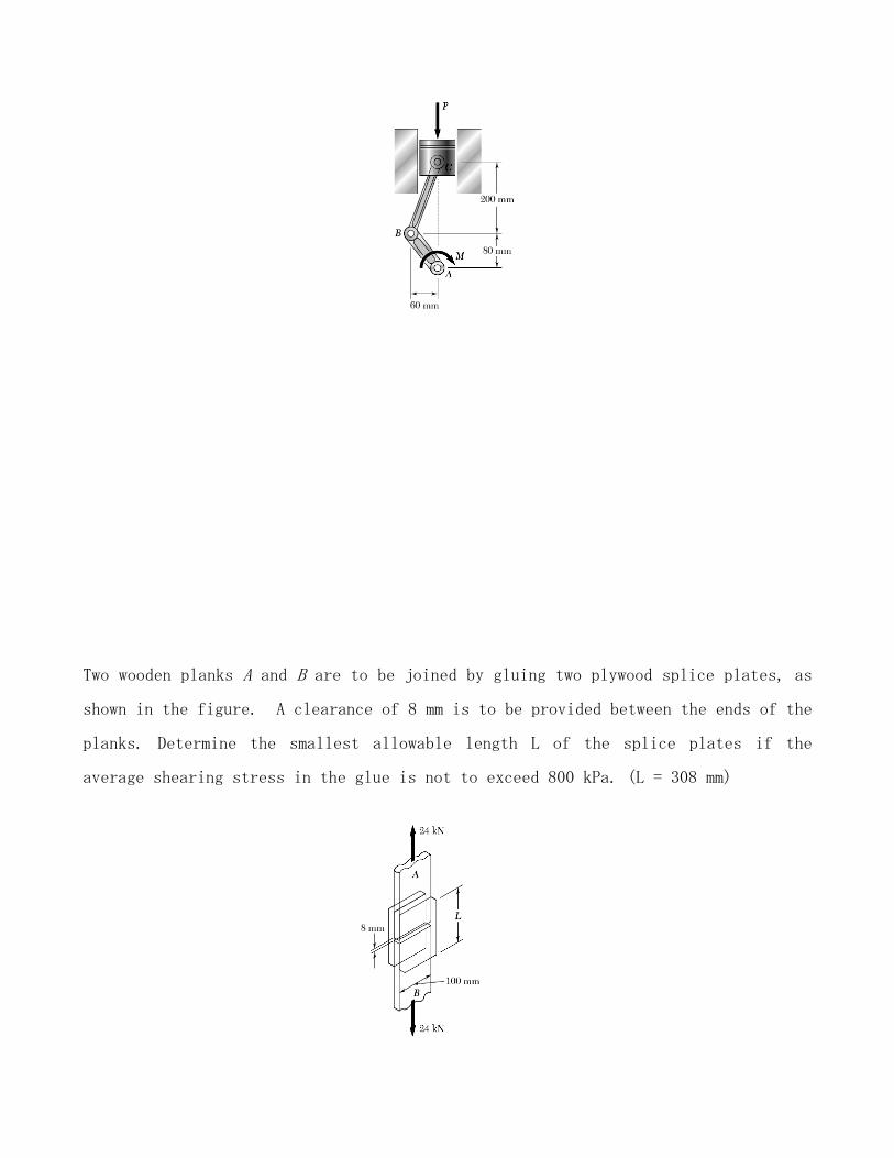
Two wooden planks A and B are to be joined by gluing two plywood splice plates, as
shown in the figure. A clearance of 8 mm is to be provided between the ends of the
planks. Determine the smallest allowable length L of the splice plates if the
average shearing stress in the glue is not to exceed 800 kPa. (L = 308 mm)
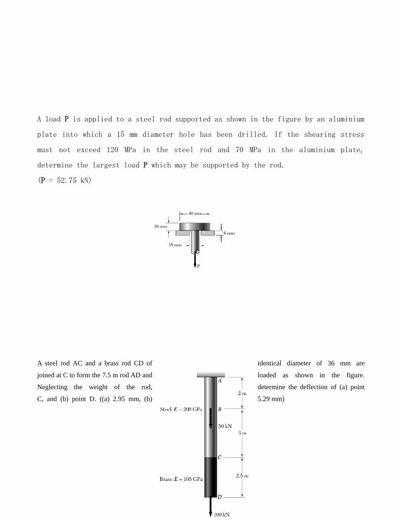
A load P is applied to a steel rod supported as shown in the figure by an aluminium
plate into which a 15 mm diameter hole has been drilled. If the shearing stress
must not exceed 120 MPa in the steel rod and 70 MPa in the aluminium plate,
determine the largest load P which may be supported by the rod.
(P = 52.75 kN)
A steel rod AC and a brass rod CD of identical diameter of 36 mm are
joined at C to form the 7.5 m rod AD and loaded as shown in the figure.
Neglecting the weight of the rod, determine the deflection of (a) point
C, and (b) point D. ((a) 2.95 mm, (b) 5.29 mm)

The mechanism shown in the figure consists of two Aluminium (E =75 Gpa) bars AB and CD of cross-sectional area
of 125 mm2 supporting a rigid member BC. Determine the deflection of the point E.
A steel tube of 32-mm outer diameter and a 4-mm thickness is placed in a rigid vise such that its jaws just touch the
ends of the tube without exerting any load on them. The two forces shown are then applied to the tube. After these
forces are applied, the vise is adjusted to decrease the distance between its jaws by 0.2 mm. Determine (a) the forces
exerted by the vise on the tube at A and D, (b) the change in length of the portion BC of the tube. Take Young's
modulus of steel E = 200 Gpa. ((a) RA = 76.6 kN, RD = 64.6 kN, (b) -0.0394 mm)

MODULE VI: TORSION

The shaft AD shown in the figure has an 8 mm diameter hole drilled through it. Determine (a) the
portion of the shaft in which the maximum shearing stress occurs, and (b) the magnitude of that stress.
((a) AB, (b) 59.7 MPa)
The shaft AE carries discs B, C and D which are subjected to torques as shown. Considering that the
entire shaft is made of steel (G = 27 GPa), determine the angle of twist between (a) C and B, and (b) D
and B. ((a) 8.54 deg, (b) 2.11 deg)
A circular solid transmission shaft of length 1.2 m is required to carry a torque of 680 Nm with a
maximum angle of twist between the ends of the shaft not exceeding 4°. Determine the required
diameter of the shaft, knowing that the shaft is made of a steel with an allowable shearing stress of 83
MPa and a modulus of rigidity of 77 GPa. (d = 35.2 mm)
MODULE VII: ANALYSIS OF BEAMS
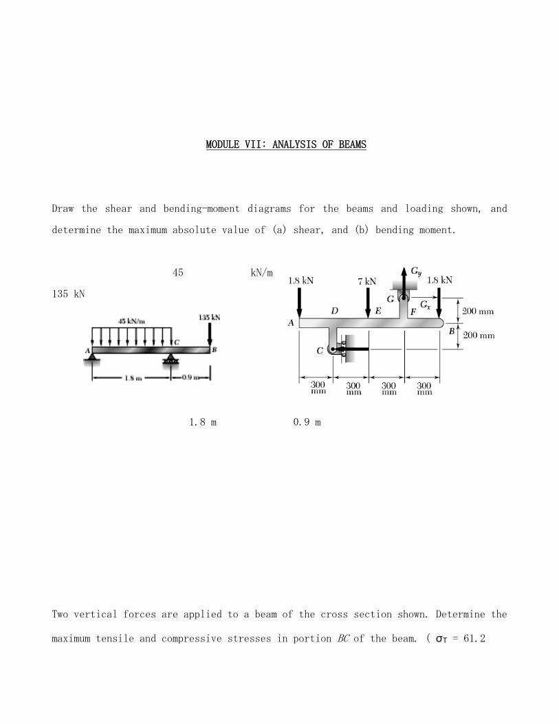
Draw the shear and bending-moment diagrams for the beams and loading shown, and
determine the maximum absolute value of (a) shear, and (b) bending moment.
45 kN/m
135 kN
1.8 m 0.9 m
Two vertical forces are applied to a beam of the cross section shown. Determine the
maximum tensile and compressive stresses in portion BC of the beam. ( σT = 61.2

Mpa, σC = -102 MPa)
Channel-like caps are attached to a plate using 10 mm diameter rivets to form a
beam section, as shown in the figure. The distance between the rivets is 80 mm. If
the allowable shear stress for the rivets is 50 Mpa, determine the allowable shear
for the beam section.

Two wooden planks are nailed to form a beam of T-section as shown (all dimensions
in mm). If a constant vertical shear of 3000 N is transmitted by the beam,
determine the maximum nail spacing if the allowable shear force per nail is 700 N.
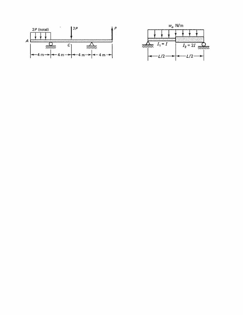
Determine the equation of the elastic curve for the loaded beams shown in the
figure. Also determine the maximum deflection and its location. Take Young's
modulus as E.