module 4 (lecture 15) - nptelnptel.ac.in/courses/105104137/module4/lecture15.pdf · module 4...
TRANSCRIPT

NPTEL – ADVANCED FOUNDATION ENGINEERING-I
Module 4
(Lecture 15)
SHALLOW FOUNDATIONS: ALLOWABLE BEARING CAPACITY AND SETTLEMENT
Topics
1.1 ALLOWABLE BEARING CAPACITY 1.2 ALLOWABLE BEARING PRESSURE IN SAND BASED ON
SETTLEMENT CONSIDERATION 1.3 FIELD LOAD TEST 1.4 PRESUMPTIVE BEARING CAPACITY 1.5 TOLERABLE SETTLEMENT OF BUILDINGS 1.6 FOUNDATION WITH SOIL REINFORCEMENT 1.7 SHALLOW FOUNDATION ON SOIL WITH REINFORCEMENT
NPTEL – ADVANCED FOUNDATION ENGINEERING-I
ALLOWABLE BEARING CAPACITY
ALLOWABLE BEARING PRESSURE IN SAND BASED ON SETTLEMENT CONSIDERATION
Meyerhof (1956) proposed a correlation for the net allowable bearing pressure for foundations with the corrected standard penetration resistance, 𝑁𝑁𝑐𝑐𝑐𝑐𝑐𝑐 . The net pressure has been defined as
𝑞𝑞net (all ) = 𝑞𝑞𝑎𝑎𝑎𝑎𝑎𝑎 − 𝛾𝛾𝐷𝐷𝑓𝑓
According to Meyerhof’s theory, for 1 in. (25.4 mm) of estimated maximum settlement
𝑞𝑞net (all )(kN/m2) = 11.98𝑁𝑁𝑐𝑐𝑐𝑐𝑐𝑐 (for 𝐵𝐵 ≤ 1.22 m [4.48]
𝑞𝑞net (all )(kN/m2) = 7.99𝑁𝑁𝑐𝑐𝑐𝑐𝑐𝑐 �3.28𝐵𝐵+1
3.28𝐵𝐵�
2 (for 𝐵𝐵 > 1.22 m) [4.49]
Where
𝑁𝑁𝑐𝑐𝑐𝑐𝑐𝑐 = corrected standard penetration number
𝑞𝑞net (all )(kip/ft2) = 𝑁𝑁𝑐𝑐𝑐𝑐𝑐𝑐4
(for 𝐵𝐵 ≤ 4 ft [4.50]
And
𝑞𝑞net (all )(kip/ft2) = 𝑁𝑁𝑐𝑐𝑐𝑐𝑐𝑐6�B+1
B�
2 (for 𝐵𝐵 ≤ 4 ft [4.51]
Since Meyerhof proposed original correlation, researchers have observed that its results are rather conservative. Later, Meyerhof (1965) suggested that the net allowable bearing pressure should be increased by about 50%. Bowles (1977) proposed that the modified form of the bearing pressure equations be expressed as
𝑞𝑞net (all )(kN/m2) = 19.16𝑁𝑁𝑐𝑐𝑐𝑐𝑐𝑐 𝐹𝐹𝑑𝑑 �𝑆𝑆𝑐𝑐
25.4� (for 𝐵𝐵 ≤ 1.22 m) [4.52]
𝑞𝑞net (all )(kN/m2) = 19.98𝑁𝑁𝑐𝑐𝑐𝑐𝑐𝑐 �3.28𝐵𝐵+1
3.28𝐵𝐵�
2𝐹𝐹𝑑𝑑 � 𝑆𝑆𝑐𝑐
25.4� (for 𝐵𝐵 > 1.22 m) [4.53]
Where
𝐹𝐹𝑑𝑑 = depth factor = 1 + 0.33 (Df/B) ≤ 1.33 [4.54]
𝑆𝑆𝑐𝑐 = torelable settlement, in mm
Again, the unit of B is meters.
NPTEL – ADVANCED FOUNDATION ENGINEERING-I
In English units
𝑞𝑞net (all )(kip/ft2) = 𝑁𝑁𝑐𝑐𝑐𝑐𝑐𝑐2.5
FdSc (for 𝐵𝐵 ≤ 4 ft) [4.55]
𝑞𝑞net (all )(kip/ft2) = 𝑁𝑁𝑐𝑐𝑐𝑐𝑐𝑐4�B+1
B�
2FdSc (for 𝐵𝐵 > 4 ft) [4.56]
Where
𝐹𝐹𝑑𝑑 is given by equation (50)
𝑆𝑆𝑐𝑐 = torebale settlement, in in.
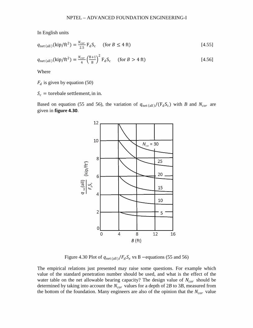
Based on equation (55 and 56), the variation of 𝑞𝑞net (all )/(FdSc) with B and 𝑁𝑁𝑐𝑐𝑐𝑐𝑐𝑐 are given in figure 4.30.
Figure 4.30 Plot of 𝑞𝑞net (all )/𝐹𝐹𝑑𝑑𝑆𝑆𝑒𝑒 vs B −equations (55 and 56)
The empirical relations just presented may raise some questions. For example which value of the standard penetration number should be used, and what is the effect of the water table on the net allowable bearing capacity? The design value of 𝑁𝑁𝑐𝑐𝑐𝑐𝑐𝑐 should be determined by taking into account the 𝑁𝑁𝑐𝑐𝑐𝑐𝑐𝑐 values for a depth of 2B to 3B, measured from the bottom of the foundation. Many engineers are also of the opinion that the 𝑁𝑁𝑐𝑐𝑐𝑐𝑐𝑐 value
NPTEL – ADVANCED FOUNDATION ENGINEERING-I
should be reduced somewhat if the water table is close to the foundation. However, the author believes that this reduction is not required because the penetration resistance reflects the location of the water table.
Meyerhof (1956) also prepared empirical relations for the net allowable bearing capacity of foundations based on the cone penetration resistance, 𝑞𝑞𝑐𝑐 :
𝑞𝑞net (all ) = 𝑞𝑞𝑐𝑐15
(for 𝐵𝐵 ≤ 1.22m and settlement of 25.4 mm) [4.57]
And
𝑞𝑞net (all ) = 𝑞𝑞𝑐𝑐25�3.28𝐵𝐵+1
3.28𝐵𝐵�
2 (for 𝐵𝐵 > 1.22m and settlement of 25.4 mm) [4.58]
Note that in equations (57 and 58) the unit of B is meters, and the units of 𝑞𝑞net (all ) and 𝑞𝑞𝑐𝑐 are kN/m2.
𝑞𝑞net (all )(lb/ft2) = qc (lb /ft2)15
(for 𝐵𝐵 ≤ 4ft and settlement of 1 in. ) [4.59]
And
𝑞𝑞net (all )(lb/ft2) = qc (lb /ft2)25
� 𝐵𝐵+125�
2 (for 𝐵𝐵 > 4ft and settlement of 1 in. ) [4.60]
Note that in equations (59 and 60), the unit of B.
The basic philosophy behind the development of these correlations is that, if the maximum settlement is not more than 1 in. (25.4 mm) for any foundation, the differential settlement would be no more than 0.75 in. (19 mm). These are probably the allowable limits for most building foundation designs.
FIELD LOAD TEST
The ultimate load-bearing capacity of a foundation, as well as the allowable bearing capacity based on tolerable settlement considerations, can be effectively determined from the field load test. It is generally referred to as the plate load test (ASTM, 1982; Test Designation D-1194-72). The plates that are used for tests in the field are usually made of steel and are 25 mm (1 in.) thick and 150 mm to 762 mm (6 in. to 30 in.) in diameter. Occasionally, square plates that are 305 mm × 305 mm (12 in. × 12 in.) are also used.
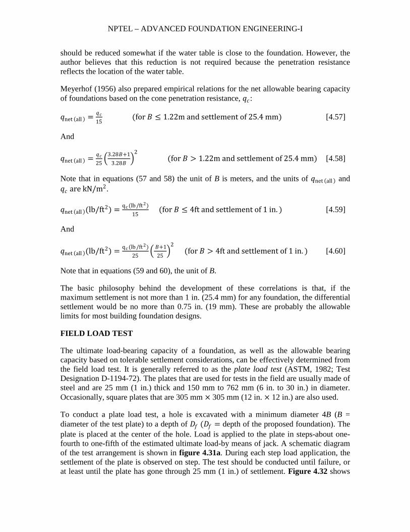
To conduct a plate load test, a hole is excavated with a minimum diameter 4B (B = diameter of the test plate) to a depth of 𝐷𝐷𝑓𝑓 (𝐷𝐷𝑓𝑓 = depth of the proposed foundation). The plate is placed at the center of the hole. Load is applied to the plate in steps-about one-fourth to one-fifth of the estimated ultimate load-by means of jack. A schematic diagram of the test arrangement is shown in figure 4.31a. During each step load application, the settlement of the plate is observed on step. The test should be conducted until failure, or at least until the plate has gone through 25 mm (1 in.) of settlement. Figure 4.32 shows
NPTEL – ADVANCED FOUNDATION ENGINEERING-I
the nature f the load-settlement curve obtained from such tests, from which the ultimate load per unit area can be determined.
Figure 4.31 Plate load test: (a) test arrangement; (b) nature of load-settlement curve
For tests in clay,
𝑞𝑞𝑢𝑢(𝐹𝐹) = 𝑞𝑞𝑢𝑢(𝑃𝑃) [4.61]
W, is
Here
𝑞𝑞𝑢𝑢(𝐹𝐹) = ultimate bearing capacity of the proposed foundation
𝑞𝑞𝑢𝑢(𝑃𝑃) = ultimate bearing capacity of the test plane
Equation (61) implies that the ultimate bearing capacity in clay is virtually independent of the size of the plate.
NPTEL – ADVANCED FOUNDATION ENGINEERING-I
For tests in sandy soils,
𝑞𝑞𝑢𝑢(𝐹𝐹) = 𝑞𝑞𝑢𝑢(𝑃𝑃)𝐵𝐵𝐹𝐹𝐵𝐵𝑃𝑃
[4.62]
Where
𝐵𝐵𝐹𝐹 = width of the foundaiton
𝐵𝐵𝑃𝑃 = width of the test plate
The allowable bearing capacity of a foundation, based on settlement considerations and for a given intensity of load, 𝑞𝑞𝑐𝑐 , is
𝑆𝑆𝐹𝐹 = 𝑆𝑆𝑃𝑃𝐵𝐵𝐹𝐹𝐵𝐵𝑃𝑃
(for clayey soil) [4.63]
And
𝑆𝑆𝐹𝐹 = 𝑆𝑆𝑃𝑃 �2𝐵𝐵𝐹𝐹
𝐵𝐵𝐹𝐹+𝐵𝐵𝑃𝑃�
2 (for sandy soil) [4.64]
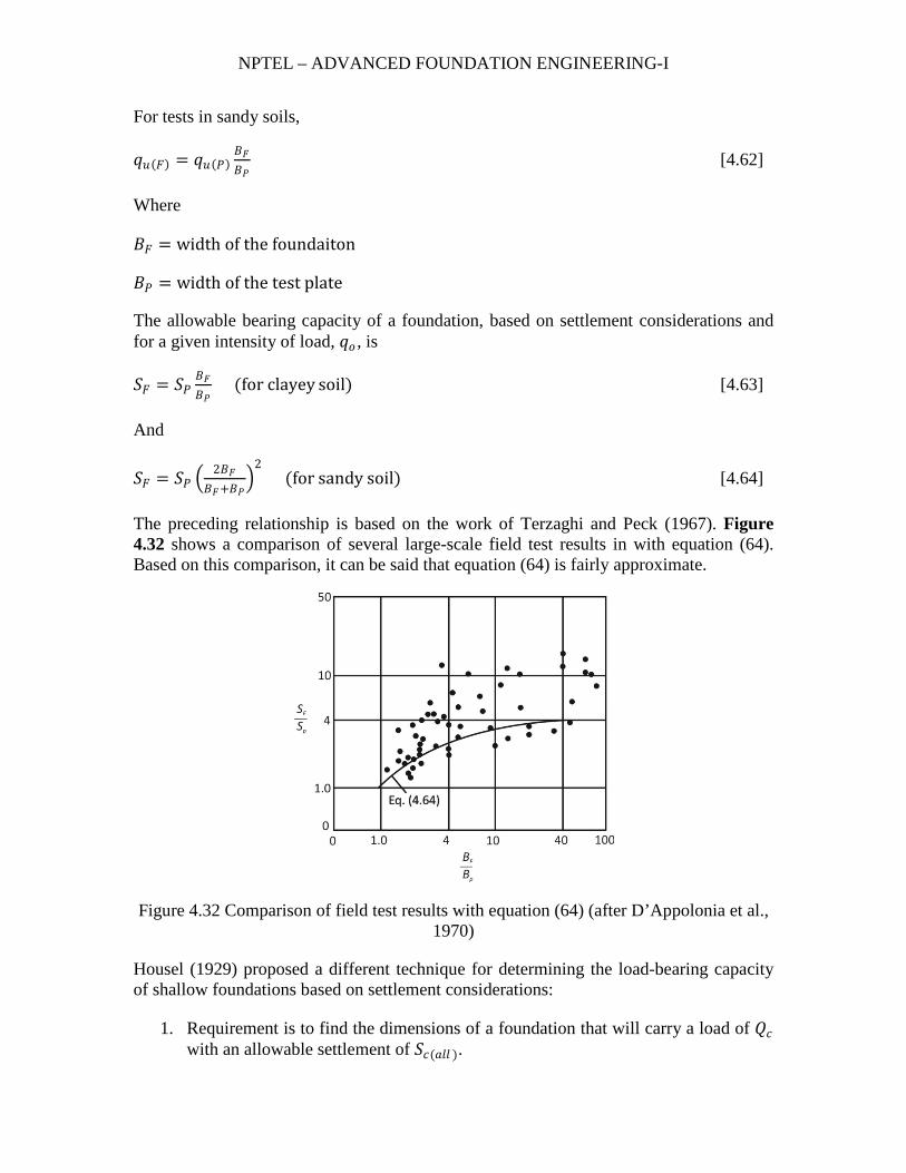
The preceding relationship is based on the work of Terzaghi and Peck (1967). Figure 4.32 shows a comparison of several large-scale field test results in with equation (64). Based on this comparison, it can be said that equation (64) is fairly approximate.
Figure 4.32 Comparison of field test results with equation (64) (after D’Appolonia et al., 1970)
Housel (1929) proposed a different technique for determining the load-bearing capacity of shallow foundations based on settlement considerations:
1. Requirement is to find the dimensions of a foundation that will carry a load of 𝑄𝑄𝑐𝑐 with an allowable settlement of 𝑆𝑆𝑐𝑐(𝑎𝑎𝑎𝑎𝑎𝑎 ).
NPTEL – ADVANCED FOUNDATION ENGINEERING-I
2. Conduct two plate load tests with plates of diameters 𝐵𝐵1 and 𝐵𝐵2. 3. From the load-settlement curves obtained in step 2, determine the total loads on
the plates (𝑄𝑄1 and 𝑄𝑄2) that correspond to the settlement of 𝑆𝑆𝑐𝑐(𝑎𝑎𝑎𝑎𝑎𝑎 ). For plate no. 1, the total load can be expressed as 𝑄𝑄1 = 𝐴𝐴1𝑚𝑚 + 𝑃𝑃1𝑛𝑛 [4.65]
Similarly, for plate no. 2
𝑄𝑄2 = 𝐴𝐴2𝑚𝑚 + 𝑃𝑃2𝑛𝑛 [4.66]
Where
𝐴𝐴1,𝐴𝐴2 = areas of the plate no. 1 and no. 2, respectively
𝑃𝑃1,𝑃𝑃2 = perimeter of the plates no. 1 and no. 2, respectively
𝑚𝑚,𝑛𝑛 =two constants that corresponds to the bearing presure and perimeter shear, respectively
The values of 𝑚𝑚 and 𝑛𝑛 can be determined by solving equations (65 and 66).
4. For the foundation to be designed, 𝑄𝑄𝑐𝑐 = 𝐴𝐴𝑚𝑚 + 𝑃𝑃𝑛𝑛 [4.67] Where 𝐴𝐴 = area of the foundation 𝑃𝑃 = perimeter of the foundation
Because 𝑄𝑄𝑐𝑐 ,𝑚𝑚 and 𝑛𝑛 are known, equation (67) can be solved determine foundations width.
Example 7
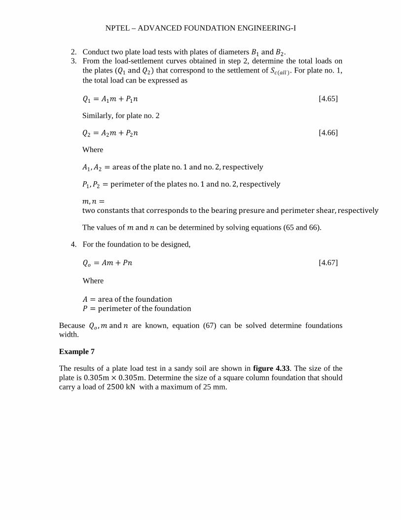
The results of a plate load test in a sandy soil are shown in figure 4.33. The size of the plate is 0.305m × 0.305m. Determine the size of a square column foundation that should carry a load of 2500 kN with a maximum of 25 mm.
NPTEL – ADVANCED FOUNDATION ENGINEERING-I
Figure 4.33
Solution
The problem has to be solved by trial and error. Use the following table and equation (64):
𝑄𝑄𝑐𝑐(kN)(1) Assume width 𝐵𝐵𝐹𝐹(m)(2)
𝑞𝑞𝑐𝑐=𝑄𝑄𝑐𝑐𝐵𝐵𝐹𝐹2
(kN
/m2)(3)
𝑆𝑆𝑃𝑃 corresponding to 𝑞𝑞𝑐𝑐 in col. 3 (mm) (4)
𝑆𝑆𝐹𝐹 from equation (64) (mm) (5)
2500 4.0 156.25 4.0 13.81
2500 3.0 277.80 8.0 26.37
2500 3.2 244.10 6.8 22.67
So, a column footing with dimensions of 3.2 m × 3.2 m will be appropriate.
Example 8
The results of two plate load tests are given in the following table:
Plate diameter, B (m) Total load, 𝑄𝑄 (kN) Settlement (mm)
0.305 32.2 20
0.610 71.8 20

NPTEL – ADVANCED FOUNDATION ENGINEERING-I
A square column foundation has to be constructed to carry a total load of 715 kN. The tolerable settlement is 20 m. determine the size of the foundation.
Solution
Use equations (65 and 66):
32.2 = 𝜋𝜋4
(0.305)2𝑚𝑚 + 𝜋𝜋(0.305)𝑛𝑛 [a]
71.8 = 𝜋𝜋4
(0.610)2𝑚𝑚 + 𝜋𝜋(0.610)𝑛𝑛 [b]
From (a) and (b),
𝑚𝑚 = 50.68 kN/m2
𝑛𝑛 = 29.75 kN/m
For the foundation to be designed [equation (67)],
𝑄𝑄𝑐𝑐 = 𝐴𝐴𝑚𝑚 + 𝑃𝑃𝑛𝑛
Or
𝑄𝑄𝑐𝑐 = 𝐵𝐵𝐹𝐹2𝑚𝑚 + 4𝐵𝐵𝐹𝐹𝑛𝑛
For 𝑄𝑄𝑐𝑐 = 715 kN,
715 = 𝐵𝐵𝐹𝐹2(50.68) + 4𝐵𝐵𝐹𝐹(29.75)
Or
50.68𝐵𝐵𝐹𝐹2 + 119𝐵𝐵𝐹𝐹 − 715 = 0
𝐵𝐵𝑓𝑓 ≈ 2.8 m
Example 9
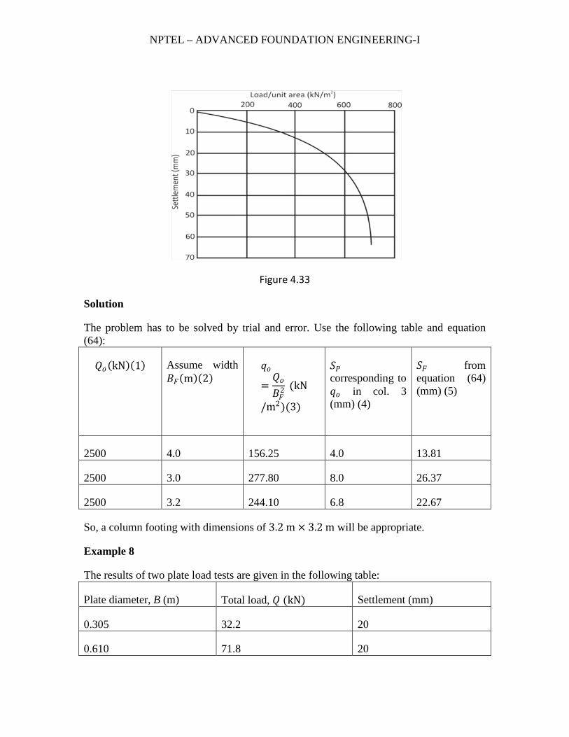
A shallow square foundation for a column is to be constructed. It must carry a net vertical load of 1000 kN. The foundation soil is sand. The standard penetration numbers obtained from field exploration are given in figure 4.34. Assume that the depth of the foundation will be 1.5 m and the tolerable settlement is 25.4 mm. determine the size of the foundation.
NPTEL – ADVANCED FOUNDATION ENGINEERING-I
Figure 4.34
Solution
The field standard penetration numbers need to be corrected by using the Liao and Whitman relationship (table 4 from chapter 2). This is done in the following table
Depth (m) Field value of 𝑁𝑁𝐹𝐹 𝜎𝜎 ′𝑣𝑣(kN/m2) Corrected 𝑁𝑁𝑐𝑐𝑐𝑐𝑐𝑐 )
2 3 31.4 7
4 7 62.8 9
6 12 94.2 12
8 12 125.6 11
10 16 157.0 13
12 13 188.4 9
14 12 206.4 8
16 14 224.36 9
18 18 242.34 11
Rounded off
NPTEL – ADVANCED FOUNDATION ENGINEERING-I
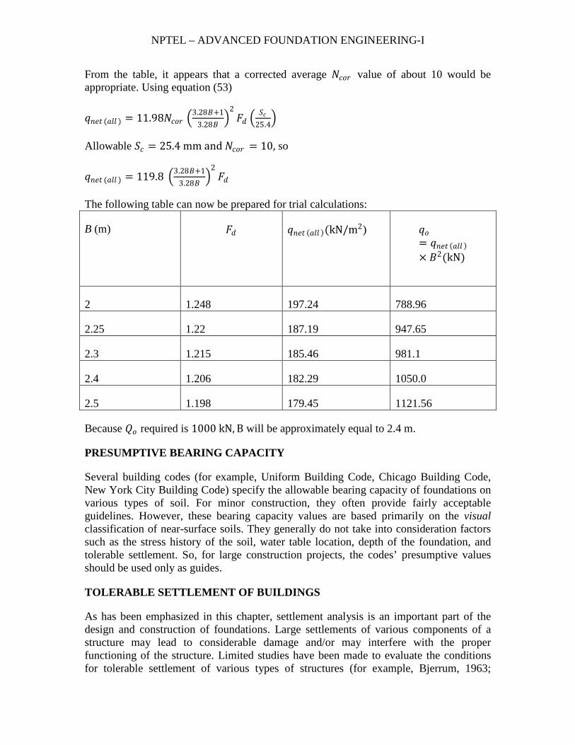
From the table, it appears that a corrected average 𝑁𝑁𝑐𝑐𝑐𝑐𝑐𝑐 value of about 10 would be appropriate. Using equation (53)
𝑞𝑞𝑛𝑛𝑒𝑒𝑐𝑐 (𝑎𝑎𝑎𝑎𝑎𝑎 ) = 11.98𝑁𝑁𝑐𝑐𝑐𝑐𝑐𝑐 �3.28𝐵𝐵+1
3.28𝐵𝐵�
2𝐹𝐹𝑑𝑑 �
𝑆𝑆𝑐𝑐25.4
�
Allowable 𝑆𝑆𝑐𝑐 = 25.4 mm and 𝑁𝑁𝑐𝑐𝑐𝑐𝑐𝑐 = 10, so
𝑞𝑞𝑛𝑛𝑒𝑒𝑐𝑐 (𝑎𝑎𝑎𝑎𝑎𝑎 ) = 119.8 �3.28𝐵𝐵+13.28𝐵𝐵
�2𝐹𝐹𝑑𝑑
The following table can now be prepared for trial calculations:
B (m) 𝐹𝐹𝑑𝑑 𝑞𝑞𝑛𝑛𝑒𝑒𝑐𝑐 (𝑎𝑎𝑎𝑎𝑎𝑎 )(kN/m2) 𝑞𝑞𝑐𝑐= 𝑞𝑞𝑛𝑛𝑒𝑒𝑐𝑐 (𝑎𝑎𝑎𝑎𝑎𝑎 )× 𝐵𝐵2(kN)
2 1.248 197.24 788.96
2.25 1.22 187.19 947.65
2.3 1.215 185.46 981.1
2.4 1.206 182.29 1050.0
2.5 1.198 179.45 1121.56
Because 𝑄𝑄𝑐𝑐 required is 1000 kN, B will be approximately equal to 2.4 m.
PRESUMPTIVE BEARING CAPACITY
Several building codes (for example, Uniform Building Code, Chicago Building Code, New York City Building Code) specify the allowable bearing capacity of foundations on various types of soil. For minor construction, they often provide fairly acceptable guidelines. However, these bearing capacity values are based primarily on the visual classification of near-surface soils. They generally do not take into consideration factors such as the stress history of the soil, water table location, depth of the foundation, and tolerable settlement. So, for large construction projects, the codes’ presumptive values should be used only as guides.
TOLERABLE SETTLEMENT OF BUILDINGS
As has been emphasized in this chapter, settlement analysis is an important part of the design and construction of foundations. Large settlements of various components of a structure may lead to considerable damage and/or may interfere with the proper functioning of the structure. Limited studies have been made to evaluate the conditions for tolerable settlement of various types of structures (for example, Bjerrum, 1963;
NPTEL – ADVANCED FOUNDATION ENGINEERING-I
Burland and Worth, 1974; Grant et al., 1974; Polshin and Tokar, 1957; and Wahls, 1981). Wahls (1981) has provided an excellent review of these studies.
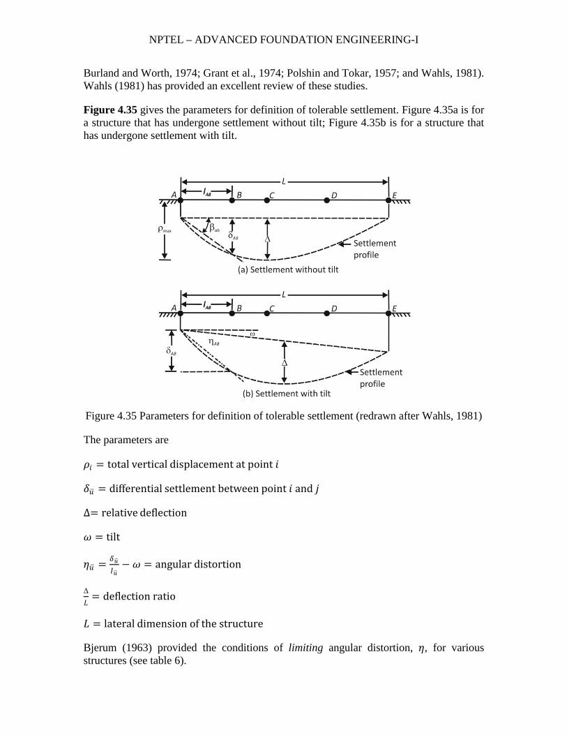
Figure 4.35 gives the parameters for definition of tolerable settlement. Figure 4.35a is for a structure that has undergone settlement without tilt; Figure 4.35b is for a structure that has undergone settlement with tilt.
Figure 4.35 Parameters for definition of tolerable settlement (redrawn after Wahls, 1981)
The parameters are
𝜌𝜌𝑖𝑖 = total vertical displacement at point 𝑖𝑖
𝛿𝛿�̈�𝑢 = differential settlement between point 𝑖𝑖 and 𝑗𝑗
∆= relative deflection
𝜔𝜔 = tilt
𝜂𝜂�̈�𝑢 = 𝛿𝛿�̈�𝑢𝐼𝐼�̈�𝑢− 𝜔𝜔 = angular distortion
Δ𝐿𝐿
= deflection ratio
𝐿𝐿 = lateral dimension of the structure
Bjerum (1963) provided the conditions of limiting angular distortion, 𝜂𝜂, for various structures (see table 6).

NPTEL – ADVANCED FOUNDATION ENGINEERING-I
Polshin and Tokar (1957) presented the settlement criteria of the 1955 U.S.S.R. Building Code. These criteria were based on experience gained from observations of foundation settlement over 25 years. Tables 7 and 8 present the criteria.
FOUNDATION WITH SOIL REINFORCEMENT
SHALLOW FOUNDATION ON SOIL WITH REINFORCEMENT
It was discussed in chapter 3 that the ultimate bearing capacity of shallow foundations can be improved by including tensile reinforcement such as metallic strips, geotextiles, and geogrids in the soil supporting the foundation. The procedure for designing shallow foundations for limiting settlement condition (that is, allowable bearing capacity) with layers of geogrid as reinforcement is still n the research and development stages. However, the problem of allowable bearing capacity of shallow foundations resting on granular soil reinforced with metallic strips was studied in detail by Binquet and Lee (1975a, b), who proposed the rational design method presented in the following sections.
Table 6 Limiting Angular Distortion as Recommended by Bjerrum
Category of potential damage 𝜂𝜂
Danger to machinery sensitive to settlement 1/750
Danger to frames with diagonals 1/600
Safe limit for no cracking of buildings b 1/500
First cracking of panel walls 1/300
Difficulties with overhead cranes 1/300
Tilting of high rigid buildings becomes visible
1/250
Considerable cracking of panel and brick walls
1/150
Danger of structural damage to general buildings
1/150
Safe limit for flexible brick walls, 𝐿𝐿/𝐻𝐻 >4 b
1/150
a After Wahls (1981)
b Safe limits include a factor of safety. 𝐻𝐻 = height of building

NPTEL – ADVANCED FOUNDATION ENGINEERING-I
Table 7 Allowable Settlement Criteria: 1995 U.S.S.R .Building Code
Type of structure Sand and hard clay Plastic clay
(a)𝜂𝜂
Civil-and industrial-building column foundations:
For steel and reinforced concrete structure
For end rows of columns with brick cladding
For structures where auxillary strain does not arise during nonuniform settlement of foundations
Tilt of smokestacks, towers, and so on
Craneways
0.002
0.007
0.005
0.004
0.003
0.002
0.001
0.005
0.004
0.003
(b)Δ/𝐿𝐿
Plain brick walls:
For multistory dwelling and civil buildings
at 𝐿𝐿/𝐻𝐻 ≤ 3
at 𝐿𝐿/𝐻𝐻 ≥ 5
for one-story mills
0.0003
0.0005
0.0010
0.0004
0.0007
0.0010
a After Wahls (1981). 𝐻𝐻 = height of building
Table 8 Allowable Average Settlement for Different Building Types
Type of building Allowable average settlement, in (mm)
Building with plain brick walls

NPTEL – ADVANCED FOUNDATION ENGINEERING-I
𝐿𝐿/𝐻𝐻 ≥ 2.5
𝐿𝐿/𝐻𝐻 ≤ 1.5
Building with brick walls, reinforced with reinforced concrete or reinforced brick
Framed building
Solid reinforced concrete foundations of smokestacks, soils, towers, and so on
3(80)
4(100)
6(150)
4(100)
12(300)
After Wahls (1981). 𝐻𝐻 = height of building