module 3 - rajagiri school of engineering & technology v/me... · •(the reversed magnetizing...
TRANSCRIPT

Module 3
Magnetic Particle Inspection (MPI)

Magnetic Particle Inspection (MPI)
OR Magnetic Particle Testing (MPT)
• It is used for the testing of ferromagnetic materials which can be easily magnetized.
• Most of iron, alloys of Ni and Co and many of the precipitation hardening steels.
• Capable of detecting flaws open to surface and just below the surface.
• The MPI equipment is cheap, robust and can be handled by semiskilled personnel.
• Doesn’t require elaborate protection as for radiography.
Asst. Prof. Vishnu Sankar,DME,RSET

• MPI method is used to inspect a variety of product forms including castings, forgings and weldments.
• Many different industries use MPI such as structural steel, automotive, petrochemical, power generation, and aerospace industries.
• Underwater inspection is another area where MPI may be used to test items such as offshore structures and underwater pipelines.
Asst. Prof. Vishnu Sankar,DME,RSET

Basic Principles
•The concept can be considered as a combination of two NDT methods: magnetic flux leakage testing and visual testing
•For the case of a bar magnet, the magnetic field is in and around the magnet.
•Any place that a magnetic line of force exits or enters the magnet is called a “pole”.
•Magnetic lines of force exit the magnet from north pole and enter from the south pole.
Asst. Prof. Vishnu Sankar,DME,RSET

Basic Principles…
•When a bar magnet is broken in the center of its length, two complete bar magnets with magnetic poles on each end of each piece will result.
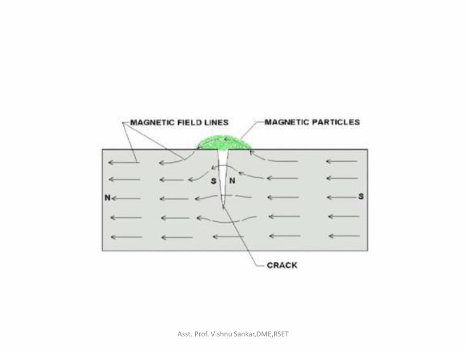
•If the magnet is just cracked but not broken completely into two, a north and south pole will form at each edge of the crack.
Asst. Prof. Vishnu Sankar,DME,RSET

Basic Principles…
•The magnetic field exits the north pole and reenters at the south pole.
•The magnetic field spreads out when it encounters the small air gap created by the crack,
• because the air cannot support as much magnetic field per unit volume as the magnet can.
•When the field spreads out, it appears to leak out of the material and, thus is called a flux leakage field.
Asst. Prof. Vishnu Sankar,DME,RSET

• If iron particles are sprinkled on a cracked magnet, the particles will be attracted to and cluster not only at the poles at the ends of the magnet, but also at the poles at the edges of the crack.
• This cluster of particles is much easier to see than the actual crack and this is the basis for magnetic particle inspection.
Asst. Prof. Vishnu Sankar,DME,RSET

• The first step in a magnetic particle testing is to magnetize the component that is to be inspected.
• If any defects on or near the surface are present, the defects will create a leakage field.
• After the component has been magnetized, iron particles, either in a dry or wet suspended form, are applied to the surface of the magnetized part.
• The particles will be attracted and cluster at the flux leakage fields, thus forming a visible indication that the inspector can detect.
Asst. Prof. Vishnu Sankar,DME,RSET
Asst. Prof. Vishnu Sankar,DME,RSET
Advantages of MPI
• High sensitivity (small discontinuities can be detected).
• Indications are produced directly on the surface of the part and constitute a visual representation of the flaw.
• Minimal surface preparation (no need for paint removal)
• Portable (materials are available in aerosol spray cans)
• Low cost (materials and associated equipment are relatively inexpensive)
Asst. Prof. Vishnu Sankar,DME,RSET

Disadvantages of MPI
• Only surface and near surface defects can be detected.
• Only applicable to ferromagnetic materials.
• Relatively small area can be inspected at a time.
• Only materials with a relatively nonporous surface can be inspected.
• The inspector must have direct access to the surface being inspected.
Asst. Prof. Vishnu Sankar,DME,RSET

Basic physics of MPI • Magnetism
• The ability of a ferromagnetic material to attract other ferromagnetic materials.
• The concept of magnetism centers around the magnetic field and what is known as a dipole.
• "magnetic field" - a volume of space where there is a change in energy within that volume.
• The location where a magnetic field exits or enters a material is called a magnetic pole.
• Magnetic poles have never been detected in isolation but always occur in pairs, hence the name dipole.
Asst. Prof. Vishnu Sankar,DME,RSET

• The source of magnetism lies in the basic building block of all matter, the atom.
• Atoms are composed of protons, neutrons and electrons.
• The protons and neutrons are located in the atom's nucleus and the electrons are in constant motion around the nucleus.
• Electrons carry a negative electrical charge and produce a magnetic field as they move through space.
• A magnetic field is produced whenever an electrical charge is in motion.
Asst. Prof. Vishnu Sankar,DME,RSET

• When an electric current flows through a conductor, the movement of electrons through the conductor causes a magnetic field to form around the conductor.
• The magnetic field can be detected using a compass.
• Since all matter is comprised of atoms, all materials are affected in some way by a magnetic field;
• however, materials do not react the same way to the magnetic field.
Asst. Prof. Vishnu Sankar,DME,RSET
Reaction of Materials to Magnetic Field
• When a material is placed within a magnetic field, the magnetic forces of the material's electrons will be affected.
• This effect is known as Faraday's Law of Magnetic Induction.
• According to their interaction with a magnetic field, materials can be classified as:
• Diamagnetic materials
• Paramagnetic materials
• Ferromagnetic materials
Asst. Prof. Vishnu Sankar,DME,RSET

Diamagnetic materials
• They have a weak, negative susceptibility to magnetic fields.
• They are slightly repelled by a magnetic field,
• and the material does not retain the magnetic properties when the external field is removed.
• In these materials all the electrons are paired so there is no permanent net magnetic moment per atom.
• Most elements in the periodic table, including copper, silver, and gold, are diamagnetic.
Asst. Prof. Vishnu Sankar,DME,RSET

Paramagnetic materials
• They have a small, positive susceptibility to magnetic fields.
• These materials are slightly attracted by a magnetic field,
• and the material does not retain the magnetic properties when the external field is removed.
• Paramagnetic have some unpaired electrons.
• Examples of paramagnetic materials include magnesium, molybdenum, and lithium.
Asst. Prof. Vishnu Sankar,DME,RSET

Ferromagnetic materials • They have a large, positive susceptibility to an
external magnetic field. • They exhibit a strong attraction to magnetic fields
and are able to retain their magnetic properties after the external field has been removed.
• Ferromagnetic materials have some unpaired electrons so their atoms have a net magnetic moment.
• They get their strong magnetic properties due to the presence of magnetic domains.
• In these domains, large numbers of atom's moments are aligned parallel so that the magnetic force within the domain is strong.
Asst. Prof. Vishnu Sankar,DME,RSET

• When a ferromagnetic material is in the unmagnetized state, the domains are nearly randomly organized and the net magnetic field for the part as a whole is zero
• When a magnetizing force is applied, the domains become aligned to produce a strong magnetic field within the part.
• Iron, nickel, and cobalt are examples of ferromagnetic materials.
• Components made of these materials are commonly inspected using the magnetic particle method.
Asst. Prof. Vishnu Sankar,DME,RSET

Asst. Prof. Vishnu Sankar,DME,RSET

The Hysteresis Loop and Magnetic Properties
• A great deal of information can be learned about the magnetic properties of a material by studying its hysteresis loop.
• shows the relationship between the induced magnetic flux density (B) and the magnetizing force (H).
• It is often referred to as the B-H loop.
Asst. Prof. Vishnu Sankar,DME,RSET

Hysteresis Loop
•The loop is generated by measuring the magnetic flux of a ferromagnetic material while the magnetizing force is changed.
•A ferromagnetic material that has never been previously magnetized or has been thoroughly demagnetized will follow the dashed line as H is increased.
Asst. Prof. Vishnu Sankar,DME,RSET

• As the line demonstrates, the greater the amount of current applied (H+), the stronger the magnetic field in the component (B+).
• At point "a“ almost all of the magnetic domains are aligned and an additional increase in the magnetizing force will produce very little increase in magnetic flux.
• The material has reached the point of magnetic saturation.
Asst. Prof. Vishnu Sankar,DME,RSET

• When H is reduced to zero, the curve will move from point "a" to point "b".
• At this point, it can be seen that some magnetic flux remains in the material even though the magnetizing force is zero.
• This is referred to as the point of retentivity on the graph and indicates the level of residual magnetism in the material
• (Some of the magnetic domains remain aligned but some have lost their alignment).
Asst. Prof. Vishnu Sankar,DME,RSET

• As the magnetizing force is reversed, the curve moves to point "c", where the flux has been reduced to zero.
• This is called the point of coercivity on the curve.
• (the reversed magnetizing force has flipped enough of the domains so that the net flux within the material is zero).
• The force required to remove the residual magnetism from the material is called the coercive force or coercivity of the material.
Asst. Prof. Vishnu Sankar,DME,RSET

• As the magnetizing force is increased in the negative direction, the material will again become magnetically saturated but in the opposite direction, point "d".
• Reducing H to zero brings the curve to point "e“. • It will have a level of residual magnetism equal to
that achieved in the other direction. • Increasing H back in the positive direction will
return B to zero. • Notice that the curve did not return to the origin
of the graph because some force is required to remove the residual magnetism.
• The curve will take a different path from point "f" back to the saturation point where it will complete the loop.
Asst. Prof. Vishnu Sankar,DME,RSET

Magnetic properties • Retentivity -
• it is a material's ability to retain a certain amount of residual magnetic field when the magnetizing force is removed after achieving saturation
• (The value of B at point b on the hysteresis curve).
Asst. Prof. Vishnu Sankar,DME,RSET

• Residual Magnetism or Residual Flux - The magnetic flux density that remains in a material when the magnetizing force is zero.
• Note that residual magnetism and retentivity are the same when the material has been magnetized to the saturation point.
• However, the level of residual magnetism may be lower than the retentivity value when the magnetizing force did not reach the saturation level.
Asst. Prof. Vishnu Sankar,DME,RSET

• Coercive Force - The amount of reverse magnetic field which must be applied to a magnetic material to make the magnetic flux return to zero.
• (The value of H at point c on the hysteresis curve).
Asst. Prof. Vishnu Sankar,DME,RSET

• Reluctance - Is the opposition that a ferromagnetic material shows to the establishment of a magnetic field.
• Reluctance is analogous to the resistance in an electrical circuit.
• Reluctance of a material determines the magnitude of the flux produced.
Asst. Prof. Vishnu Sankar,DME,RSET

• Permeability, μ - A property of a material that describes the ease with which a magnetic flux is established in the material.
• Numerically expressed as B/H.
• A material with high permeability has low reluctance and vice versa.
Asst. Prof. Vishnu Sankar,DME,RSET

Quantifying Magnetic Properties
• The various characteristics of magnetism can be measured and expressed quantitatively.
• Different systems of units can be used for quantifying magnetic properties.
• SI Units: four base units; meter, kilogram, second, and Ampere.
Asst. Prof. Vishnu Sankar,DME,RSET

Magnetic field strength (H)
•The unit for magnetic field strength H is (A/m).
•A magnetic field strength of 1 A/m is produced
at the center of a single circular conductor with a 1
meter diameter carrying a steady current of 1 ampere.
Asst. Prof. Vishnu Sankar,DME,RSET
Magnetic flux density, B
• The number of magnetic lines of force cutting through a plane of a given area at a right angle is known as the magnetic flux density, B.
• The flux density or magnetic induction has the tesla as its unit.
• One tesla is equal to 1 Newton/(A/m).
• From these units, it can be seen that the flux density is a measure of the force applied to a particle by the magnetic field.
Asst. Prof. Vishnu Sankar,DME,RSET

• The total number of lines of magnetic force in a
material is called magnetic flux, ɸ. • The strength of the flux is determined by the
number of magnetic domains that are aligned within a material.
• The total flux is simply the flux density applied over an area.
• Flux carries the unit of weber, which is simply a tesla-meter2.
Asst. Prof. Vishnu Sankar,DME,RSET
Permeability
• Permeability (μ) is a material property that describes the ease with which a magnetic flux is established in a component.
• It is the ratio of the flux density (B) created within a material to the magnetizing field (H)
• Represented by the equation: μ = B/H
Asst. Prof. Vishnu Sankar,DME,RSET

•This equation describes the slope of the curve at any point on the hysteresis loop.
•The maximum permeability is the point where the slope of the B/H curve for the unmagnetized material is the greatest.
•This point is often taken as the point where a straight line from the origin is tangent to the B/H curve.
Asst. Prof. Vishnu Sankar,DME,RSET

•The shape of the hysteresis loop tells a great deal about the material being magnetized.
•The hysteresis curves of two different materials are shown in the graph.
Asst. Prof. Vishnu Sankar,DME,RSET

• Relative to other materials, a material with a wider hysteresis loop has:
• Lower Permeability
• Higher Retentivity
• Higher Coercivity
• Higher Reluctance
• Higher Residual Magnetism
Asst. Prof. Vishnu Sankar,DME,RSET

• Relative to other materials, a material with a narrower hysteresis loop has:
• Higher Permeability
• Lower Retentivity
• Lower Coercivity
• Lower Reluctance
• Lower Residual Magnetism
Asst. Prof. Vishnu Sankar,DME,RSET

• In magnetic particle testing, the level of residual magnetism is important.
• Residual magnetic fields are affected by the permeability, which can be related to the carbon content and alloying of the material.
• A component with high carbon content will have low permeability,
• and will retain more magnetic flux than a material with low carbon content.
Asst. Prof. Vishnu Sankar,DME,RSET

Magnetic Field Orientation and Flaw Detectability
• The orientation of the crack relative to the magnetic lines of force determines if the crack can or cannot be detected.
• There are two general types of magnetic fields that can be established within a component.
• A longitudinal magnetic field .
• A circular magnetic field
Asst. Prof. Vishnu Sankar,DME,RSET

A longitudinal magnetic field
• It has magnetic lines of force that run parallel to the long axis of the part.
•Longitudinal magnetization of a component can be accomplished using the longitudinal field set up by a coil or solenoid.
•It can also be accomplished using permanent magnets or electromagnets.
Asst. Prof. Vishnu Sankar,DME,RSET

A circular magnetic field
• It has magnetic lines of force that run circumferentially around the perimeter of a part.
•A circular magnetic field is induced in two ways:
• by either passing current through the component
•or by passing current through a conductor surrounded by the component.
Asst. Prof. Vishnu Sankar,DME,RSET

• The best detection of defects occurs when the lines of magnetic force are established at right angles to the longest dimension of the defect.
• This orientation creates the largest disruption of the magnetic field within the part and the greatest flux leakage at the surface of the part.
•If the magnetic field is parallel to the defect, the field will see little disruption and no flux leakage field will be produced.
Asst. Prof. Vishnu Sankar,DME,RSET
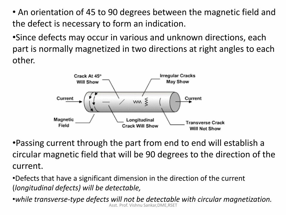
• An orientation of 45 to 90 degrees between the magnetic field and the defect is necessary to form an indication.
•Since defects may occur in various and unknown directions, each part is normally magnetized in two directions at right angles to each other.
•Passing current through the part from end to end will establish a circular magnetic field that will be 90 degrees to the direction of the current. •Defects that have a significant dimension in the direction of the current (longitudinal defects) will be detectable,
•while transverse-type defects will not be detectable with circular magnetization.
Asst. Prof. Vishnu Sankar,DME,RSET

Methods of magnetization
• There are a variety of methods that can be used to establish a magnetic field in a component.
• It is common to classify the magnetizing methods as direct and indirect.
Asst. Prof. Vishnu Sankar,DME,RSET

Magnetization Using Direct Induction (Direct Magnetization)
• With direct magnetization, current is passed directly through the component.
• The flow of current causes a circular magnetic field to form in and around the conductor.
• Care must be taken to ensure that good electrical contact is established and maintained between the test equipment and the test component,
• to avoid damage of the component (due to arcing or overheating at high resistance points).
Asst. Prof. Vishnu Sankar,DME,RSET

Methods - Direct magnetization
1. Clamping the component between two electrical contacts contact heads (Head shot).
a. Circular
b. radial
2. using clamps or prods
Asst. Prof. Vishnu Sankar,DME,RSET

Magnetization Using Indirect Induction (Indirect Magnetization)
• Indirect magnetization is accomplished by using a strong external magnetic field to establish a magnetic field within the component.
• In these techniques magnetic flux is induced into the specimen either by the use of a permanent magnet or by flowing current through a coil or a conductor.
• As with direct magnetization, there are several ways that indirect magnetization can be accomplished.
Asst. Prof. Vishnu Sankar,DME,RSET

Methods - Indirect magnetization
• Indirect magnetization is accomplished by using a strong external magnetic field.
1. use of permanent magnets
2. Electromagnets (Yokes)
3. Using the magnetic field of a current carrying conductor (central conductor).
4. Use of coils and solenoids – Longitudinal- (coil shot)
Asst. Prof. Vishnu Sankar,DME,RSET

Head shot techniques • Circular
• Clamping the component between two electrical contacts in a special piece of equipment.
• Current is passed through the component and a circular magnetic field is established.
• When the magnetizing current is stopped, a residual magnetic field will remain within the component.
• The strength of the induced magnetic field is proportional to the amount of current passed through the component.
Asst. Prof. Vishnu Sankar,DME,RSET

Asst. Prof. Vishnu Sankar,DME,RSET

Radial Magnetization
Asst. Prof. Vishnu Sankar,DME,RSET

Prod Magnetization
Asst. Prof. Vishnu Sankar,DME,RSET

Prod Magnetization
• Using clamps or prods, which are attached or placed in contact with the component.
• Electrical current flows through the component from contact to contact.
• The current sets up a circular magnetic field around the path of the current.
Asst. Prof. Vishnu Sankar,DME,RSET

Asst. Prof. Vishnu Sankar,DME,RSET

Indirect Magnetization 1. Use of permanent magnets
• low cost method of establishing a magnetic field.
• However, their use is limited due to lack of control of the field strength.
• Difficulty of placing and removing strong permanent magnets from the component.
Asst. Prof. Vishnu Sankar,DME,RSET

Asst. Prof. Vishnu Sankar,DME,RSET

• Magnetic materials such as hard steel and some alloys, offer high resistance to magnetization due to their low permeability
• But they possess the characteristic of retaining the magnetism.
• Permanent magnet in the form of horse shoe is used to inspect the material.
• The actual strength of the field at any point depends on the strength of magnet and the distance between the poles.
• The distance between their poles cannot be varied nor the actual strength of the magnet.
• Inspection of active high pressure gas pipelines.
Asst. Prof. Vishnu Sankar,DME,RSET

2. Using Electromagnets
• A soft metal core made into a magnet by the passage of electric current.
• Electromagnets in the form of an adjustable horseshoe magnet (called a yoke).
• The iron core and the work piece form a closed magnetic circuit.
• Eliminate the problems associated with permanent magnets and are used extensively in industry.
Asst. Prof. Vishnu Sankar,DME,RSET

Asst. Prof. Vishnu Sankar,DME,RSET

Asst. Prof. Vishnu Sankar,DME,RSET

• Electromagnets only exhibit a magnetic flux when electric current is flowing around the soft iron core.
• With yoke magnetization, burning of the test piece is avoided because only the magnetic field is transmitted into it, no current enters the test piece.
• Furthermore, yoke magnetization can be used for test objects with non magnetic surface layers provided the layer thickness is not greater than 40 mm.
Asst. Prof. Vishnu Sankar,DME,RSET

3. Using central conductor
• Inducting a magnetic field in a material is by using the magnetic field of a current carrying conductor.
• A circular magnetic field can be established in cylindrical components by using a central conductor.
• For inspection of hollow cylindrical shaped test objects.
Asst. Prof. Vishnu Sankar,DME,RSET

Asst. Prof. Vishnu Sankar,DME,RSET

• Typically, one or more cylindrical components are hung from a solid copper bar running through the inside diameter
• Current is passed through the copper bar and the resulting circular magnetic field establishes a magnetic field within the test components.
• suitable for inspection of many small sized cylindrical shaped articles such as springs, nuts and short cylindrical washers…
• The technique is employed to find longitudinal discontinuities inside and outside the cylinders.
Asst. Prof. Vishnu Sankar,DME,RSET

4. Use of coil or solenoid (Coil shot)
• When the length of a component is several times larger than its diameter, a longitudinal magnetic field can be established in the component.
• The component is placed longitudinally in the concentrated magnetic field that fills the center of a coil or solenoid.
Asst. Prof. Vishnu Sankar,DME,RSET

Asst. Prof. Vishnu Sankar,DME,RSET

Asst. Prof. Vishnu Sankar,DME,RSET
Types of Magnetizing Current
• Electric current is often used to establish the magnetic field in components during magnetic particle inspection.
• Alternating current (AC) and direct current (DC) are the two basic types of current commonly used.
• The type of current used can have an effect on the inspection results.
Asst. Prof. Vishnu Sankar,DME,RSET
Direct Current (DC) • Direct current (DC) flows continuously in one
direction at a constant voltage. • A battery is the most common source of direct
current. • The current flows from the positive to the negative
terminal, though electrons flow in the opposite direction.
• DC is very desirable when inspecting for subsurface defects because DC generates a magnetic field that penetrates deeper into the material.
• In ferromagnetic materials, the magnetic field produced by DC generally penetrates the entire cross-section of the component.
Asst. Prof. Vishnu Sankar,DME,RSET

Alternating Current (AC) • Alternating current (AC) reverses in direction at a rate of 50 or 60
cycles per second.
• Since AC is readily available in most facilities, it is convenient to make use of it for magnetic particle inspection.
• However, when AC is used to induce a magnetic field in ferromagnetic materials, the magnetic field will be limited to a thin layer at the surface of the component.
• This phenomenon is known as the "skin effect" and occurs because the changing magnetic field generates eddy currents in the test object.
• The eddy currents produce a magnetic field that opposes the primary field, thus reducing the net magnetic flux below the surface.
• Therefore, it is recommended that AC be used only when the inspection is limited to surface defects.
Asst. Prof. Vishnu Sankar,DME,RSET

Rectified Alternating Current
• Clearly, the skin effect limits the use of AC since many inspection applications call for the detection of subsurface defects.
• AC can be converted to current that is very much like DC through the process of rectification.
• With the use of rectifiers, the reversing AC can be converted to a one directional current.
• The three commonly used types of rectified current are:
1. Half Wave Rectified Alternating Current (HWAC)
2. Full Wave Rectified Alternating Current (FWAC) (Single Phase)
3. Three Phase Full Wave Rectified Alternating Current
Asst. Prof. Vishnu Sankar,DME,RSET

Half Wave Rectified Alternating Current (HWAC)
• When single phase alternating current is passed through a rectifier, current is allowed to flow in only one direction.
• The reverse half of each cycle is blocked out so that a one directional, pulsating current is produced.
• The current rises from zero to a maximum and then returns to zero.
• No current flows during the time when the reverse cycle is blocked out.
• Since half of the current is blocked out, the amperage is half of the unaltered AC.
• This type of current is often referred to as half wave DC or pulsating DC.
• The pulsation of the HWAC helps magnetic particle indications formed by vibrating the particles and giving them added mobility where that is especially important when using dry particles.
• HWAC is most often used to power electromagnetic yokes. Asst. Prof. Vishnu Sankar,DME,RSET
Full Wave Rectified Alternating Current (FWAC) (Single Phase)
• Full wave rectification inverts the negative current to positive current rather than blocking it out.
• This produces a pulsating DC with no interval between the pulses.
• Filtering is usually performed to soften the sharp polarity switching in the rectified current.
• While particle mobility is not as good as half-wave AC due to the reduction in pulsation, the depth of the subsurface magnetic field is improved.
Asst. Prof. Vishnu Sankar,DME,RSET

Three Phase Full Wave Rectified Alternating Current
• Three phase current is often used to power industrial equipment.
• Highly desirable for magnetic particle testing because when it is rectified and filtered, the resulting current very closely resembles direct current.
• Stationary magnetic particle equipment wired with three phase AC will usually have the ability to magnetize with AC or DC (three phase full wave rectified), providing the inspector with the advantages of each current form.
Asst. Prof. Vishnu Sankar,DME,RSET

Asst. Prof. Vishnu Sankar,DME,RSET

Demagnetization • After conducting a magnetic particle inspection, it
is usually necessary to demagnetize the component.
• Permanent magnetic fields can: affect machining by causing cuttings to cling to a
component. interfere with electronic equipment such as a
compass. create a condition known as "arc blow" in the welding
process. Arc blow may cause filler metal to be repelled from the weld.
cause abrasive particles to cling to bearing or faying surfaces (surfaces that are in contact at a joint ) and increase wear.
Asst. Prof. Vishnu Sankar,DME,RSET

Demagnetization methods 1. Heating above curie temperature • The most effective way to demagnetize a material
is by heating the material above its curie temperature.
• When steel is heated above its curie temperature then it is cooled back down, the orientation of the magnetic domains will become randomized again.
• The material should also be placed with its longest axis in an east-west orientation to avoid any influence of the Earth's magnetic field.
• However, it is often inconvenient to heat a material above its curie temperature
Asst. Prof. Vishnu Sankar,DME,RSET

2. Alternating current demagnetization
• An A.C coil is the most common method of demagnetization
• The coil is usually designed to operate at line voltage and frequency (usually 50 c.p.s).
• When the part is placed in the coil, it is subjected to a reversing field due to the cyclic action of the current.
Asst. Prof. Vishnu Sankar,DME,RSET

Asst. Prof. Vishnu Sankar,DME,RSET

3. Reversing DC demagnetization
• In demagnetization with reversed direct current, the desired magnetic field is obtained by means of a coil or passage of current through the part itself.
• The direct current is alternately reversed in direction and reduced in amplitude.
• If a coil is used, the part is left in the coil until the demagnetization cycle has been completed.
• The method is very effective and usually employed on articles which are difficult to demagnetize.
• Approximately 30 reversals and reduction in current values help in achieving reliably demagnetization of the articles.
Asst. Prof. Vishnu Sankar,DME,RSET

4. AC circular field demagnetization
• This method is similar to A.C demagnetization except the current is passed directly into the parts.
• The magnitude of the current is systematically reduced to zero by some suitable device.
• This method is used for large parts.
Asst. Prof. Vishnu Sankar,DME,RSET

5. AC and DC yoke demagnetization
• Yokes are usually used for demagnetizing small parts having very high coercive forces.
• Some AC yokes are similar in operation to the AC coil method whereby the part is passed between the pole faces (max. field intensity) and then withdrawn.
• Direct current yokes are usually based upon the reversing DC method.
Asst. Prof. Vishnu Sankar,DME,RSET

6. Vibration
• This means of demagnetization is not recommended, due to possible damage of the part under test.
Asst. Prof. Vishnu Sankar,DME,RSET

Continuous and Residual techniques of MPI
• There are 4 techniques in this method – Dry continuous
– Dry residual
– Wet continuous
– Wet residual
• There are advantages and disadvantages associated with each technique
• Careful selection must be made depending upon the application.
Asst. Prof. Vishnu Sankar,DME,RSET

• The term continuous is used when magnetic particles are applied while current is still flowing.
• Residual is used when the material has sufficient retentivity to allow application of magnetic particles after the current has stopped.
• Dry – the magnetic particles are applied in fine particle form.
• Wet – particles are applied suspended in a liquid carrier ( kerosene or other petroleum distillates or water).
Asst. Prof. Vishnu Sankar,DME,RSET

Dry continuous
• Uses dry particles that are applied while magnetizing force is on.
• The particle application must stop before the current flow stops.
• Detects sub-surface defects as dry particles have higher permeability than particles in a wet suspension.
• Applying particles during magnetization provides maximum sensitivity since flux density will be at its maximum during current flow.
Asst. Prof. Vishnu Sankar,DME,RSET

• Relatively poor mobility when used with DC current.
• Can be improved by using half wave rectified or AC current.
• Extensively used for field inspection using prods or yokes.
Asst. Prof. Vishnu Sankar,DME,RSET

Dry Residual
• Magnetizing current is applied for a brief period which produces a residual magnetic field.
• Dry particles are applied after magnetizing force is stopped.
• Suitable for materials with high retentivity.
• This must be determined prior to selecting the technique.
Asst. Prof. Vishnu Sankar,DME,RSET
• The leakage field produced will be weaker thereby reducing the sensitivity.
• Small and subsurface defects are difficult to detect.
• Lack of vibratory action during particle application also reduces sensitivity due to decrease in particle mobility.
• Main advantage – multiple parts or batches can be magnetized simultaneously, then examined individually after particle application.
Asst. Prof. Vishnu Sankar,DME,RSET

Wet continuous
• Uses particles suspended in a liquid carrier and is applied simultaneously with the magnetizing current.
• Compared to dry particles the suspended particles are of a lower permeability, hence less favorable for the detection of lightly subsurface defects.
• Kerosene and petroleum distillates. • Expensive and may produce health and
flammability problems. • But they don’t constitute a corrosion source.
Asst. Prof. Vishnu Sankar,DME,RSET

• Water - inexpensive , readily available, possess no health or flammability hazards but is a source of corrosion.
• Using corrosion inhibitive additives can reduce the corrosion risk.
• Improved mobility of particles makes this technique suitable for detection of small surface defects.
• Additionally, the suspension will adhere to complex shapes better than dry particles due to surface tension.
• In this technique the suspension flow should stop before the current stops, otherwise the indications will be washed away.
Asst. Prof. Vishnu Sankar,DME,RSET

Wet Residual
• Also uses the suspended particles
• But suspension is applied after the magnetizing force is removed.
• Residual method will be of lower sensitivity than continuous method,
• But has the advantage of increased inspection speed due to multiple part or batch inspection possibilities.
Asst. Prof. Vishnu Sankar,DME,RSET

Magnetization Equipment for Magnetic Particle Testing
• A variety of equipment exists to establish the magnetic field for magnetic particle testing.
• One way to classify equipment is based on its portability.
• Some equipment is designed to be portable so that inspections can be made in the field,
• and some is designed to be stationary for ease of inspection in the laboratory or manufacturing facility.
Asst. Prof. Vishnu Sankar,DME,RSET

Portable Equipment
• Permanent Magnets
• Permanent magnets can be used for magnetic particle inspection as the source of magnetism (bar magnets or horseshoe magnets).
• The use of industrial magnets is not popular because they are very strong (they require significant strength to remove them from the surface, about 250 N for some magnets)
• and thus they are difficult and sometimes dangerous to handle.
Asst. Prof. Vishnu Sankar,DME,RSET

• However, permanent magnets are sometimes used by divers for inspection in underwater environments or other areas, such as explosive environments, where electromagnets cannot be used.
• Permanent magnets can also be made small enough to fit into tight areas where electromagnets might not fit.
Asst. Prof. Vishnu Sankar,DME,RSET

Asst. Prof. Vishnu Sankar,DME,RSET

• Electromagnetic Yokes
• a very common piece of equipment that is used to establish a magnetic field.
• A switch is included in the electrical circuit so that the current and, therefore, the magnetic field can be turned on and off.
• They can be powered with AC from a wall socket or by DC from a battery pack.
• This type of magnet generates a very strong magnetic field in a local area where the poles of the magnet touch the part being inspected.
• Some yokes can lift weights in excess of 40 pounds.
Asst. Prof. Vishnu Sankar,DME,RSET

Asst. Prof. Vishnu Sankar,DME,RSET

Prods
Asst. Prof. Vishnu Sankar,DME,RSET

• Prods • Prods are handheld electrodes, • pressed against the surface of the component
being inspected to make contact for passing electrical current (AC or DC) through the metal.
• Prods are typically made from copper and have an insulated handle to help protect the operator.
• One of the prods has a trigger switch so that the current can be quickly and easily turned on and off.
• Sometimes the two prods are connected by any insulator, to facilitate one hand operation.
• This is referred to as a dual prod and is commonly used for weld inspections.
Asst. Prof. Vishnu Sankar,DME,RSET

Asst. Prof. Vishnu Sankar,DME,RSET

• However, caution is required when using prods because electrical arcing can occur,
• and cause damage to the component if proper contact is not maintained between the prods and the component surface.
• For this reason, the use of prods is not allowed when inspecting aerospace and other critical components.
• To prevent arcing, the prod tips should be inspected frequently to ensure that they are not oxidized, covered with scale or other contaminant, or damaged.
Asst. Prof. Vishnu Sankar,DME,RSET

Portable Coils and Conductive Cables
• Coils and conductive cables are used to establish a longitudinal magnetic field within a component.
• Coils typically have three or five turns of a copper cable within the molded frame.
• A foot switch is often used to energize the coil.
Asst. Prof. Vishnu Sankar,DME,RSET

• Also, flexible conductive cables can be wrapped around a component to form a coil.
• The number of wraps is determined by the magnetizing force needed and, the length of the cable.
• Normally, the wraps are kept as close together as possible.
• When using a coil or cable wrapped into a coil, amperage is usually expressed in ampere-turns.
• Ampere-turns is the amperage shown on the amp meter times the number of turns in the coil.
Asst. Prof. Vishnu Sankar,DME,RSET

Asst. Prof. Vishnu Sankar,DME,RSET

Portable Power Supplies
Asst. Prof. Vishnu Sankar,DME,RSET

Portable Power Supplies
• Portable power supplies are used to provide the necessary electricity to the prods, coils or cables.
• commercially available in a variety of sizes. • Small power supplies generally provide up to 1,500A of
half-wave DC or AC. • They are small and light enough to be carried and
operate on either 120V or 240V electrical service. • When more power is necessary, mobile power supplies
with wheels can be used so that they can be rolled where needed.
• These units also operate on 120V or 240V electrical service and can provide up to 6,000A of AC or half-wave DC.
Asst. Prof. Vishnu Sankar,DME,RSET

Stationery Equipment
Asst. Prof. Vishnu Sankar,DME,RSET

Stationery Equipment
• Stationary magnetic particle inspection equipment is designed for use in laboratory or production environment.
• The most common stationary system is the wet horizontal (bench) unit.
• Wet horizontal units are designed to allow for batch inspections of a variety of components.
• The units have head and tail stocks (similar to a lathe) with electrical contact that the part can be clamped between.
• A circular magnetic field is produced with direct magnetization.
Asst. Prof. Vishnu Sankar,DME,RSET

• Most coils have five turns and can be obtained in a variety of sizes.
• The wet magnetic particle solution is collected and held in a tank.
• A pump and hose system is used to apply the particle solution to the components being inspected.
• Some of the systems offer a variety of options in electrical current used for magnetizing the component (AC, half wave DC, or full wave DC).
• In some units, a demagnetization feature is built in, which uses the coil and decaying AC.
Asst. Prof. Vishnu Sankar,DME,RSET

Measuring Magnetic Fields
• It is very important to be able to determine the direction and intensity of the magnetic field.
• The field intensity must be high enough to cause an indication to form, but not too high to cause non-relevant indications to mask relevant indications.
• Also, after magnetic inspection it is often needed to measure the level of residual magnetism.
• The two devices commonly used for quantitative measurement of magnetic fields in MPI are the field indicator and the Hall-effect meter, which is also called a gauss meter.
Asst. Prof. Vishnu Sankar,DME,RSET

Field Indicators • Field indicators are small mechanical devices that
utilize a soft iron vane that is deflected by a magnetic field.
• The vane is attached to a needle that rotates and moves the pointer for the scale.
• Field indicators can be adjusted and calibrated so that quantitative information can be obtained.
• However, the measurement range of field indicators is usually small due to the mechanics of the device.
• This limited range makes them best suited for measuring the residual magnetic field after demagnetization.
Asst. Prof. Vishnu Sankar,DME,RSET

Asst. Prof. Vishnu Sankar,DME,RSET

Hall-Effect (Gauss/Tesla) Meter
• A Hall-effect meter is an electronic device that provides a digital readout of the magnetic field strength in Gauss or Tesla units.
• Commonly used to measure the tangential field strength on the surface of the part.
• The meter uses a very small conductor element at the tip of the probe.
• By placing the probe next to the surface, the meter measures the intensity of the field in the air adjacent to the component when a magnetic field is applied.
• it can be used for measurement of residual magnetic fields, and it can be used repetitively.
• such devices must be periodically calibrated. Asst. Prof. Vishnu Sankar,DME,RSET

Asst. Prof. Vishnu Sankar,DME,RSET

Quantitative Quality Indicator (QQI) • It is often the preferred method of assuring proper
field direction and adequate field strength (it is used with the wet method only).
• The QQI is a thin strip (0.05 or 0.1 mm thick) of AISI 1005 steel with a specific pattern, such as concentric circles or a plus sign, etched on it.
• The QQI is placed directly on the surface, with the itched side facing the surface, and it is usually fixed to the surface using a tape and the component is then magnetized and particles applied.
• When the field strength is adequate, the particles will adhere over the engraved pattern and provide information about the field direction.
Asst. Prof. Vishnu Sankar,DME,RSET

Asst. Prof. Vishnu Sankar,DME,RSET

Pie Gage
•The pie gage is a disk of highly permeable material divided into four, six, or eight sections by non-ferromagnetic material.
•The divisions serve as artificial defects that radiate out in different directions from the center.
•The sections are furnace brazed and copper plated.
•The gage is placed on the test piece copper side up and the test piece is magnetized.
Asst. Prof. Vishnu Sankar,DME,RSET

• After particles are applied and the excess removed, the indications provide the inspector the orientation of the magnetic field.
• Pie gages are mainly used on flat surfaces such as weldments or steel castings where dry powder is used with a yoke or prods.
• The gauge should be demagnetized between readings.
Asst. Prof. Vishnu Sankar,DME,RSET

Procedure for testing a component
a) Surface preparation of component Normally machined or plated surfaces don’t
require any surface treatment other than degreasing.
Loose rust and scale should be removed to prevent contamination of the ink.
Paint should be locally removed so as to provide adequate contact area for the current flow.
Other painted parts only require degreasing unless the color of the paint is same as that of the particles in the ink.
Asst. Prof. Vishnu Sankar,DME,RSET

b) Initial demagnetization
Components which have been machined on magnetic chuck or handled in the vicinity of any magnetic field could have been magnetized partially or wholly.
It is advisable to remove this residual magnetism to avoid false indications.
Asst. Prof. Vishnu Sankar,DME,RSET

c) Degreasing and cleaning
• Adhering grease and dirt can mask defects and also contaminate the ink.
• May be carried out by spirit or trichloroethylene bath
• When a component is to be tested in-situ, the cleaning is accomplished by a clean rag or cotton waste moistened with a solvent (spirit or paraffin)
Asst. Prof. Vishnu Sankar,DME,RSET

d) Magnetization of the component
• May be carried out by following one of the methods discussed.
• It is necessary to choose suitable operating values of electrical parameters to obtain optimum magnetization of the part.
• Various sources of current can be used.
Asst. Prof. Vishnu Sankar,DME,RSET

e) Application of magnetic particles • Two classes of magnetic particles based on the
carrying agent used: wet method, dry method. • In wet method particles use a liquid carrier and
in dry method they are carried by air. • For wet method, particles are available in black
or red color and fluorescent. • In dry method, alight and even distribution of
the magnetic powder is the best type of coating, • because a heavy coating will impede the
particle movement towards leakage field. • The color is chosen to give the best contrast. • For best results the particle mean size shall be ≈
6µm and shape can be a mixture of roughly spherical and columnar.
Asst. Prof. Vishnu Sankar,DME,RSET

f) Viewing
• The black or red paste or powder indications are viewed under proper illumination (500 lux)
• Good day light is the best.
• Fluorescent paste or powder particles must be viewed under black light and the inspection area must be darkened.
Asst. Prof. Vishnu Sankar,DME,RSET

• g) Marking of defects
• All relevant indications should be marked after allowing the ink to drain.
• Video recording and photography.
• Or the area can be covered with a transparent adhesive film.
• When the film is peeled off it comes out with magnetic particles adhered corresponding to indications.
Asst. Prof. Vishnu Sankar,DME,RSET

• h) Demagnetization
• All ferromagnetic materials retain some residual magnetism after MPI. affect machining by causing cuttings to cling to a
component.
create a condition known as "arc blow" in the welding process. Arc blow may cause filler metal to be repelled from the weld.
cause abrasive particles to cling to bearing surfaces and increase wear.
Asst. Prof. Vishnu Sankar,DME,RSET

• i) Removal of ink from the component
• Ink particles can be deleterious during later assembly of the component.
• A paraffin oil wash is usually adequate to remove ink
Asst. Prof. Vishnu Sankar,DME,RSET

Interpretation and Evaluation of indications
• In any NDT process there are three essential steps:
i. Production of the indication
ii. Interpretation of the indication (as to what condition is present to have caused it)
iii. Evaluation of the condition indicated (as to its effect and seriousness from the stand point of unsuitability of the part)
Asst. Prof. Vishnu Sankar,DME,RSET

Interpretation of the indication
• The indications mean that something in the part is not normal.
• But they don’t tell exactly what the condition which has produced them.
• In MPT every pattern is produced by a magnetic disturbance setting up a leakage field,
• But further knowledge and information is needed to enable us to say really significant or not.
• Given an indication someone must interpret it in
terms of its cause. Asst. Prof. Vishnu Sankar,DME,RSET

Evaluation
• Before the part can be disposed of, a further decision remains to be made.
• Once it is determined what the condition in the part, then the condition must be evaluated,
• in terms of its effect on the non reliability of the part for its intended service.
• After this decision the part may be accepted or rejected or perhaps salvaged.
• A further cost saving analysis can often determine what control of processes can do to prevent future similar occurrences.
Asst. Prof. Vishnu Sankar,DME,RSET

Outside knowledge required
• To make a decision as to identify a defect, need considerable experience and general information regarding the part.
• The following points and sources of information should be possessed by an inspector.
Asst. Prof. Vishnu Sankar,DME,RSET

a) A knowledge of the material from which the part is made.
• Whether high or low carbon steel, and what alloys are present in what amount.
• Should know something of steels, and steel making and the character of the defects likely to occur in various types of steels.
Asst. Prof. Vishnu Sankar,DME,RSET

• c) knowledge to how metals fail and what conditions are likely to lead to such failure.
• d) Past experience with similar parts
• Such experience often indicates what to be on the look out for and helps to identify an indication when it is found.
Asst. Prof. Vishnu Sankar,DME,RSET

• b) A knowledge of the processing history of the part.
• Whether made from rolled stock, forging or casting
• Also what machining operations have been applied
• Also heat treatment it has received.
• He should know enough about such processes to be familiar with the defects each may cause to the part.
Asst. Prof. Vishnu Sankar,DME,RSET

• e) Facilities to conduct destructive tests on specimens containing indications of which the cause is not clear.
• Cutting up the part and examining the defect in section often makes possible identification of similar indications when they are encountered.
• f) A general knowledge of metallurgy is extremely helpful. Asst. Prof. Vishnu Sankar,DME,RSET

Simple tests
• Sometimes the defect is readily seen, once the exact location has been revealed by the indication.
• A low power hand glass is a most convenient pocket tool for a first check.
• If surface is rough or covered with light film of rust, polishing the area with fine emery cloth makes the defect more visible.
• Another simple check is to wipe off the indication and again apply the particles, to see whether the indication will be reproduced.
Asst. Prof. Vishnu Sankar,DME,RSET
Inspection lighting
• Magnetic particle inspection predominately relies on visual inspection to detect any indications that form.
• Therefore, lighting is a very important element of the inspection process.
• The lighting requirements are different for an inspection conducted using visible particles than they are for an inspection conducted using fluorescent particles.
Asst. Prof. Vishnu Sankar,DME,RSET

• Good Day light
• Day light varies from hour to hour, hence satisfactory lighting can be obtained using artificial light.
• Artificial light should be white.
• If colored, max. color contrast should be brought out by the lighting.
Asst. Prof. Vishnu Sankar,DME,RSET

Evaluation
• Means, deciding as to whether the condition found is a cause for rejection or whether the part may be used or salvaged.
• Decision is based on the predetermined standards.
• The problem of evaluation: whether a given defect is so located that it will endanger the satisfactory performance of the material.
Asst. Prof. Vishnu Sankar,DME,RSET

The problem of evaluation Some considerations
• A) what type of actual service stress the part will withstand and their magnitude and direction, ie, (steady, pulsating or reversing)
• Have these been experimentally determined with reasonable accuracy?
Asst. Prof. Vishnu Sankar,DME,RSET

• B) where does the defect lie wrt these stresses?
• Is it in an area of high stress or low stress and is it parallel to or at some angle to the max. stress direction ?
• c) what is the nature of the defect and how severe stress raiser it is?
Asst. Prof. Vishnu Sankar,DME,RSET

• D) what is the importance of the part to the entire structure or assembly, and how serious would the result be if the part failed?
• E) what is the history of experience with similar parts in similar service?
• Have they a record of frequent or occasional failure or do they never break?
Asst. Prof. Vishnu Sankar,DME,RSET

General evaluation rules
• General rules can’t be laid down.
• General rules are not necessary when the evaluator is equipped with adequate knowledge and experience.
• Nevertheless, sometimes inspectors have to make decisions regarding the seriousness of a defect when they lack such adequate information.
Asst. Prof. Vishnu Sankar,DME,RSET

General evaluation rules • As a guide for inspectors, a few basic
considerations may be stated.
• a) a defect of any kind lying at the surface is more likely to be harmful – the deeper it lies below the surface the less harmful it is.
• b) any defect having a principal dimension or a principal plane which lies at right angles to the direction of principal tension stress is more likely to be harmful than a defect of the same size and shape lying parallel to the stress.
Asst. Prof. Vishnu Sankar,DME,RSET

• c) Any defect which occurs in an area of high tension stress must be more carefully considered than defect of the same size and shape in an area where the tension stress is low.
• d) Defects which are sharp at the bottom, such as grinding cracks are severe stress raisers and are more likely to be harmful at any location than rounded defects.
• e) Any defect that occurs in a location close to a key way or fillet or other design stress raiser is likely to increase the effect.
Asst. Prof. Vishnu Sankar,DME,RSET

THANK YOU
Asst. Prof. Vishnu Sankar,DME,RSET