module 1d: parallel-line flat pattern development...
TRANSCRIPT

Inventor (5) Module 1D: 1D- Parallel-Line Flat Pattern Development of A Sheet-Metal Folded Model Wrapping The 3D Space of An Oblique Hexagonal Prism
1
Module 1D: Parallel-Line Flat Pattern Development of
A Sheet-Metal Folded Model Wrapping The 3D Space of an Oblique Hexagonal Prism In this Module, we will create a parallel-line flat pattern development of a sheet-
metal folded model wrapping the 3D space of an oblique hexagonal prism in Inventor. An oblique prism is one with all elements (or lateral edge lines) parallel to a central axis that is not upright (or at a 90º angle relative to horizontal), but inclined (or at any angle 0º<θ<90º relative to horizontal). The basic method to complete this task is:
• Creating the 3D solid model of an oblique prism with a hexagonal cross-
section, to be used as a Derived Part in another Inventor Sheet Metal (in).ipt file;
• Importing the 3D solid model of the oblique prism with a hexagonal cross-
section from the first file as a Derived Part, in a new Inventor Sheet Metal (in).ipt file, and creating Face features wrapping around the 3D geometry of the 3D solid model of the Derived Part.
In this Module, this basic method will be explored.
Section 1: Creating The 3D Solid Model of An Oblique Prism with A Hexagonal Cross-Section Step 1: Creating the oblique prism with a hexagonal cross-section
Launch Autodesk Inventor and start a new Sheet metal (in).ipt file under the
English tab. A new Sketch1 is automatically created on the XY Plane; rename it Construction Sketch in the Model panel; select the Project Geometry tool and the Center Point feature from the Model panel to project it onto the sketch; select the Line tool and draw a vertical line, and a horizontal line, and an angled line (the “oblique axis line”), all starting from the projected Center Point, and another horizontal line starting at the top endpoint of the vertical line (click the mouse at the appearance of the green dot snap indicator), as shown in Figure 1D-1A; next, select the General Dimension tool to apply a 60° angular dimension between the angled line and the first horizontal line, and a
© Edward Locke 2007 ([email protected]) FOR EDUCATIONAL USE ONLY. ALL RIGHTS RESERVED.
Inventor (5) Module 1D: 1D- Parallel-Line Flat Pattern Development of A Sheet-Metal Folded Model Wrapping The 3D Space of An Oblique Hexagonal Prism
2
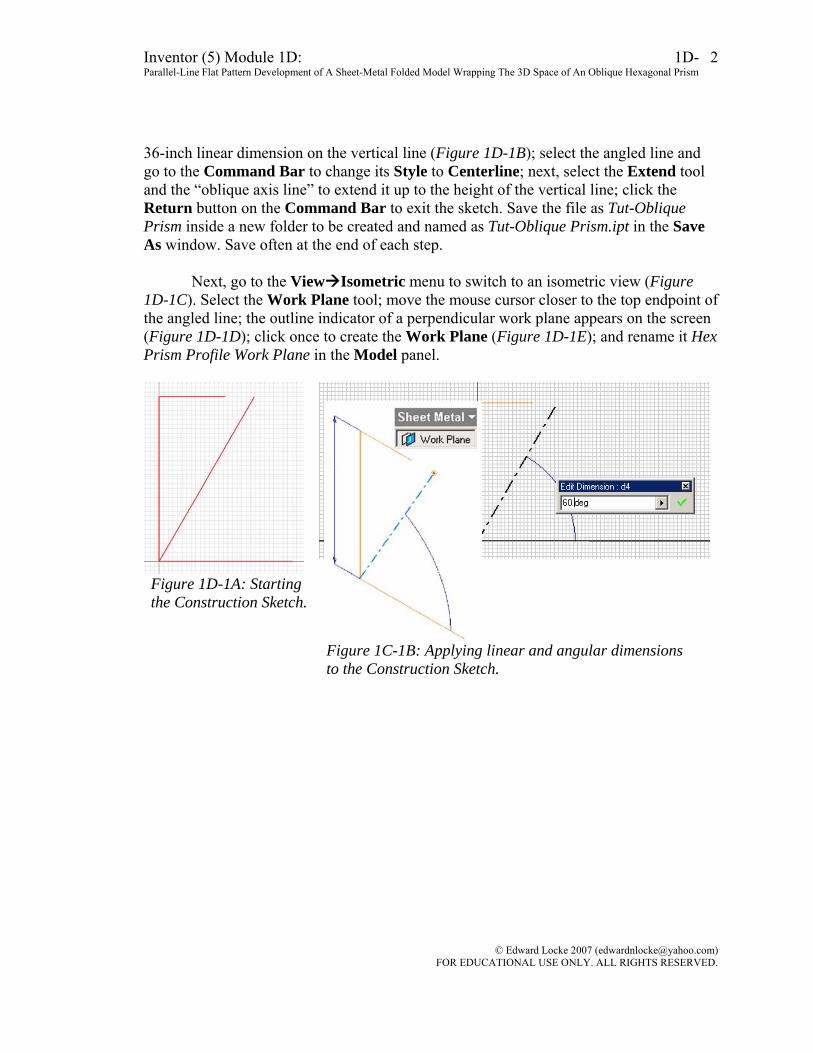
36-inch linear dimension on the vertical line (Figure 1D-1B); select the angled line and go to the Command Bar to change its Style to Centerline; next, select the Extend tool and the “oblique axis line” to extend it up to the height of the vertical line; click the Return button on the Command Bar to exit the sketch. Save the file as Tut-Oblique Prism inside a new folder to be created and named as Tut-Oblique Prism.ipt in the Save As window. Save often at the end of each step.
Next, go to the View Isometric menu to switch to an isometric view (Figure
1D-1C). Select the Work Plane tool; move the mouse cursor closer to the top endpoint of the angled line; the outline indicator of a perpendicular work plane appears on the screen (Figure 1D-1D); click once to create the Work Plane (Figure 1D-1E); and rename it Hex Prism Profile Work Plane in the Model panel.
Figure 1D-1A: Starting the Construction Sketch.
Figure 1C-1B: Applying linear and angular dimensions to the Construction Sketch.
© Edward Locke 2007 ([email protected]) FOR EDUCATIONAL USE ONLY. ALL RIGHTS RESERVED.

Inventor (5) Module 1D: 1D- Parallel-Line Flat Pattern Development of A Sheet-Metal Folded Model Wrapping The 3D Space of An Oblique Hexagonal Prism
3
Figure 1D-1C: Switching to an isometric view.
Figure 1D-1D: Selecting the Work Plane tool and moving the cursor closer to the top endpoint of the angled line.
Figure 1D-1E: Creating the Hex Prism profile Work Plane.
© Edward Locke 2007 ([email protected]) FOR EDUCATIONAL USE ONLY. ALL RIGHTS RESERVED.

Inventor (5) Module 1D: 1D- Parallel-Line Flat Pattern Development of A Sheet-Metal Folded Model Wrapping The 3D Space of An Oblique Hexagonal Prism
4
Next, click-select the Hex Prism Profile Work Plane and click the Sketch button in the Command Bar to start a new sketch and rename it Hex Prism Profile in the Model panel; select the Project Geometry tool and click-select the “oblique axis line” to project it onto the new sketch (Figure 1D-1F); a point appears on the sketch, proving that the Hex Prism Profile Work Plane just created is indeed perpendicular to the “oblique axis line;” next, select the Hex Prism Profile sketch feature in the Model panel and click the Look At tool button on the Command Bar to switch to an orthographic view; next, select the Line tool to draw a horizontal line snapped to and starting at the point projected from the “oblique axis line;” and select the General Dimension tool to apply a 24-inch linear dimension (Figure 1D-1G); next, select the Polygon tool, click the Circumscribed option button and type 6 for hexagon in the text field, in the tool’s dialog window; move the cursor closer to the projected “oblique axis line” center point, click once at the appearance of the green dot endpoint snap indicator for the center point of the hexagon, and then move the cursor closer to the other endpoint of the horizontal line just drawn, and click once to create the circumscribed hexagon (Figure 1D-1H); click the Done button to exit the tool; and click the Return button on the Command Bar to exit the sketch feature.
Figure 1D-1F: Projecting the “oblique axis line” onto the Hex Prism Profile sketch.
Figure 1D-1G: Drawing the “radius line” and applying a linear dimension.
© Edward Locke 2007 ([email protected]) FOR EDUCATIONAL USE ONLY. ALL RIGHTS RESERVED.

Inventor (5) Module 1D: 1D- Parallel-Line Flat Pattern Development of A Sheet-Metal Folded Model Wrapping The 3D Space of An Oblique Hexagonal Prism
5
Figure 1D-1H: Creating the hexagon Circumscribed hexagon.
Next, select the Extrude tool; in the tool’s dialog window, select the Distance
option and the Midplane direction, and type 36 in (inches) in the text field; the outline geometry of the oblique prism appears on the screen (Figure 1D-1J); click the OK button to create the Extrude feature and rename it Hex Prism in the Model panel (See Figure 1D-1K).
Figure 1D-1J: Creating the Hex Prism with the Extrude tool.
Figure 1D-1K: The Hex Prism Extrude feature.
© Edward Locke 2007 ([email protected]) FOR EDUCATIONAL USE ONLY. ALL RIGHTS RESERVED.

Inventor (5) Module 1D: 1D- Parallel-Line Flat Pattern Development of A Sheet-Metal Folded Model Wrapping The 3D Space of An Oblique Hexagonal Prism
6
Step 2: Truncating the prism
Select the XY Plane from the model panel; click the Look At and Sketch buttons on the Command Bar to switch to a normal view and to start a new sketch (Figure 1D-2A); and rename the new sketch Horizontal Cut Profile in the Model panel; select the Project Geometry tool and click-select the Center Point feature in the Model panel to project it onto the new sketch; next, select the Line tool and draw one horizontal line starting at and snapped to the projected Center Point, and another horizontal line above it; next, select the General Dimension tool to apply a 60 inch height dimension between the two lines (Figure 1D-2B); next, use the Line tool to draw additional horizontal and vertical lines (Figure 1D-2C); and use the Extend and Trim tools to complete two closed rectangular profiles which cover the upper and lower portions of the Hex Prism Extrude feature (Figure 1D-2D); click the Return button on the Command Bar to exit the sketch.
Figure 1D-2A: Selecting the XY Plane and switching to an orthographic normal view.
Figure 1D-2B: Projecting the Center Point, drawing two horizontal lines, and applying a height dimension.
© Edward Locke 2007 ([email protected]) FOR EDUCATIONAL USE ONLY. ALL RIGHTS RESERVED.

Inventor (5) Module 1D: 1D- Parallel-Line Flat Pattern Development of A Sheet-Metal Folded Model Wrapping The 3D Space of An Oblique Hexagonal Prism
7
Figure 1D-2C: Drawing additional horizontal and vertical lines.
Figure 1D-2D: Trimming and extending.
Next, select the Extrude tool; in the tool’s dialog window, choose the Cut option
for extrusion type, All and Midplane in the Extents section; click the OK button to cut the oblique prism (Figure 1D-2E); and rename the Extrude feature Horizontal Cut in the Model panel. The 3D solid of the oblique prism is completed (Figure 1D-2F). Save and close the file.
Figure 1D-2E: Cutting the oblique prism.
Figure 1D-2F: The completed 3D oblique prism.
© Edward Locke 2007 ([email protected]) FOR EDUCATIONAL USE ONLY. ALL RIGHTS RESERVED.

Inventor (5) Module 1D: 1D- Parallel-Line Flat Pattern Development of A Sheet-Metal Folded Model Wrapping The 3D Space of An Oblique Hexagonal Prism
8
Section 2: Creating The Sheet-Metal Part Wrapping The 3D Space of An Oblique Hexagonal Prism Step 1: Creating the Face profile sketches
Figure 1D-3A: Start a new Autodesk Inventor Sheet Metal(in).ipt file under the English tab.
Start a new Autodesk Inventor Sheet Metal (in).ipt file under the English tab
(Figure 1D-3A); a new sketch is automatically created on the XY Plane; click the Return button to exit; click-select the Sketch1 feature from the Model panel; right-click for a shortcut menu and choose Delete to delete it. Next, select the Features tool panel and select the Derived Component tool; in the Open dialog window, navigate to the Tut-Oblique Prism folder and select the Tut-Oblique Prism.ipt file (Figure 1D-3B); click the Open button; in the Derived Part dialog window (Figure 1D-3C), select the Body as Work Surface option, and click the OK button. The orange-color surface model of the oblique prism is created on the screen as reference geometry (Figure 1D-3D). Notice that the Hex Prism Profile Work Plane is also visible; if desired, then select this Work Plane feature either on the screen or from the Model panel, right-click for the shortcut menu and uncheck Visibility to make it invisible (Figure 1D-3E).
© Edward Locke 2007 ([email protected]) FOR EDUCATIONAL USE ONLY. ALL RIGHTS RESERVED.

Inventor (5) Module 1D: 1D- Parallel-Line Flat Pattern Development of A Sheet-Metal Folded Model Wrapping The 3D Space of An Oblique Hexagonal Prism
9
Figure 1D-3B: Selecting the Tut-Oblique Prism.ipt file in the Open window (left).
Figure 1D-3C: Selecting the Body as Work Surface option in the Derived Part window (right).
Figure 1D-3D: The Work Surface reference geometry of the 3D model of the oblique prism.
Figure 1D-3E: Turning off the Visibility of the Hex Prism Profile Work Plane.
Next, select the first five lateral surfaces of the Derived Component model to
create closed quadrilateral profiles for the creation of sheet-metal Face features. Click-select the first surface on the model and click the Sketch button on the Command Bar to start a new sketch (Figure 1D-3F); select the Project Geometry tool and click-select the four edges of the surface to project them onto the new sketch (Figure 1D-3G); click the
© Edward Locke 2007 ([email protected]) FOR EDUCATIONAL USE ONLY. ALL RIGHTS RESERVED.

Inventor (5) Module 1D: 1D- Parallel-Line Flat Pattern Development of A Sheet-Metal Folded Model Wrapping The 3D Space of An Oblique Hexagonal Prism
10
Return button on the Command Bar to exit the sketch. Repeat the same procedures to create all five Sketch features corresponding to the first five lateral surfaces of the oblique prism, using the Rotate tool whenever needed; and rename the Sketch features in the Model panel as Lateral Face 1 Sketch, Lateral Face 2 Sketch, Lateral Face 3 Sketch, Lateral Face 4 Sketch, and Lateral Face 5 Sketch (Figure 1D-3H through Figure 1D-3N). Save the file as Tut-Oblique Prism SM.ipt inside the same Tut-Oblique Prism folder. Save often at the end of each step.
Figure 1D-3F: Selecting the 1st lateral surface for creating the Lateral Face 1 Sketch.
Figure 1D-3G: Creating the Lateral Face 1 Sketch.
Figure 1D-3H: Selecting the 2nd lateral surface for creating the Lateral Face 2 Sketch.
Figure 1D-3J: Creating the Lateral Face 2 Sketch.
Figure 1D-3K: Selecting the 3rd lateral surface for creating the Lateral Face 2 Sketch. Figure 1D-3L: Creating the
Lateral Face 3 Sketch, and selecting the 4th lateral surface for creating the Lateral Face 4 Sketch.
© Edward Locke 2007 ([email protected]) FOR EDUCATIONAL USE ONLY. ALL RIGHTS RESERVED.

Inventor (5) Module 1D: 1D- Parallel-Line Flat Pattern Development of A Sheet-Metal Folded Model Wrapping The 3D Space of An Oblique Hexagonal Prism
11
Figure 1D-3M: Creating the Lateral Face 4 Sketch.
Figure 1D-3N: Creating the Lateral Face 5 Sketch.
Next, select the 6th surface and click the Sketch button on the Command Bar to
start the profile sketch for the last lateral surface of the oblique prism (Figure 1D-3P); use the project Geometry tool to project the four edge lines onto the sketch; and rename it Lateral Face 6 Sketch in the Model panel (Figure 1D-3Q); use the Rotate tool to rotate the model to a better position (Figure 1D-3R); next, use the Line tool to draw a vertical line by the edge where the 1st and the 6th lateral surfaces meet, on the side of the 6th surface, and extending beyond the top and bottom horizontal edges, as shown in Figure 1D-3S.
© Edward Locke 2007 ([email protected]) FOR EDUCATIONAL USE ONLY. ALL RIGHTS RESERVED.

Inventor (5) Module 1D: 1D- Parallel-Line Flat Pattern Development of A Sheet-Metal Folded Model Wrapping The 3D Space of An Oblique Hexagonal Prism
12
Figure 1D-3P: Selecting the 6th surface for the Lateral Face 6 Sketch.
Figure 1D-3Q: Projecting the four edge lines onto the new sketch.
Figure 1D-3R: Rotating the 3D model to a better position for visualization.
Next, select the General Dimension tool to apply a 0.01-inch linear dimension
between the vertical line just drawn and the projected edge line between the 1st and 6th lateral surfaces (Figure 1D-3S), this creates a tiny gap (Figure 1D-3T) between the two Face features to be created later, which allows Inventor to generate the Flat Pattern features after the completion of the Face features for all lateral surfaces of the oblique prism and the addition of a lateral edge seam; next, window-select all lines in the sketch projected or drawn so far and go to the Style drop-down menu on the Command Bar to change the lines’ Style to Normal (Figure 1D-3V), this allows lines to be trimmed); next, use the Zoom Window tool to zoom in the top-left corner of the profile; select the Trim tool to delete the projected edge line between the 1st and the 6th lateral surfaces (Figure 1D-3W), and to cut off the unneeded segments of the vertical and horizontal lines (Figure 1D-3X). Repeat the same procedures to cut off the unneeded segments of the vertical and horizontal lines at the lower-left corner of the profile (Figure 1D-3Y and Figure 1D-3Z). Click the Return button in the Command Bar to exit the sketch.
© Edward Locke 2007 ([email protected]) FOR EDUCATIONAL USE ONLY. ALL RIGHTS RESERVED.

Inventor (5) Module 1D: 1D- Parallel-Line Flat Pattern Development of A Sheet-Metal Folded Model Wrapping The 3D Space of An Oblique Hexagonal Prism
13
Figure 1D-3T: Applying a 0.01-inch dimension for the “gap.”
Figure 1D-3S: Drawing the vertical line for the “gap.”
Figure 1D-3U: The tiny “gap” needed to allow Flat Pattern feature creation.
Figure 1D-3V: Window-selecting all lines to change their style to Normal.
Figure 1D-3W: Trimming off the projected edge line between the 1st and the 6th lateral surfaces.
Figure 1D-3X: Cutting off the unneeded segments of the vertical and horizontal lines.
Figure 1D-3Y: Cutting off the unneeded segments of the vertical line at the lower-left corner of the profile.
© Edward Locke 2007 ([email protected]) FOR EDUCATIONAL USE ONLY. ALL RIGHTS RESERVED.
Inventor (5) Module 1D: 1D- Parallel-Line Flat Pattern Development of A Sheet-Metal Folded Model Wrapping The 3D Space of An Oblique Hexagonal Prism
14
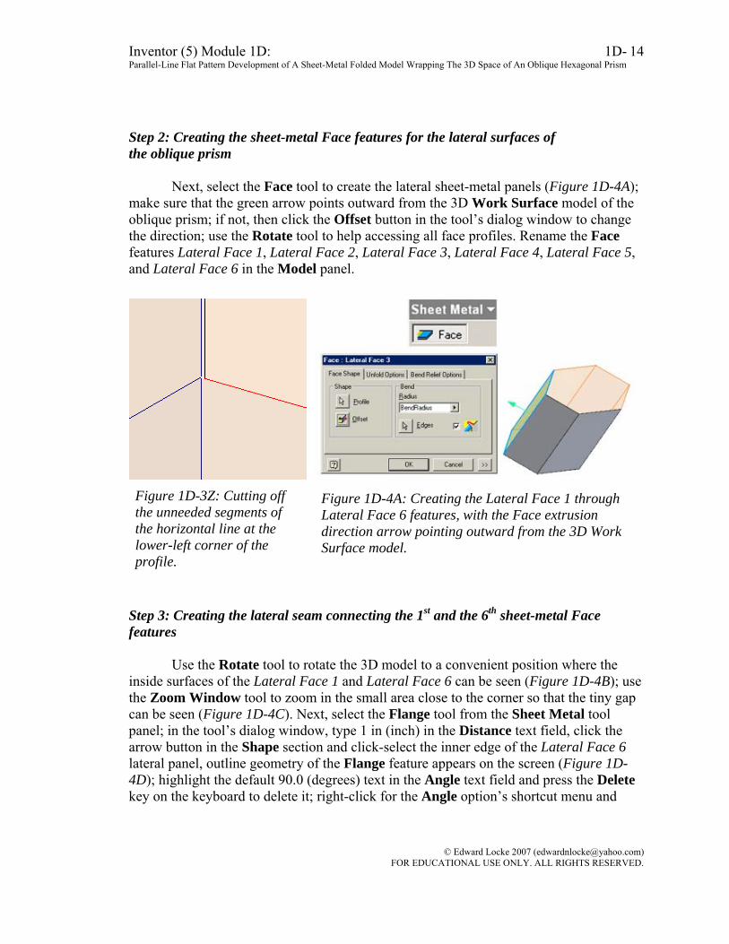
Step 2: Creating the sheet-metal Face features for the lateral surfaces of
Next, select the Face tool to create the lateral sheet-metal panels (Figure 1D-4A); make s
,
rk
tep 3: Creating the lateral seam connecting the 1st and the 6th sheet-metal Face
Use the Rotate tool to rotate the 3D model to a convenient position where the inside s se
e
the oblique prism
ure that the green arrow points outward from the 3D Work Surface model of the oblique prism; if not, then click the Offset button in the tool’s dialog window to change the direction; use the Rotate tool to help accessing all face profiles. Rename the Face features Lateral Face 1, Lateral Face 2, Lateral Face 3, Lateral Face 4, Lateral Face 5and Lateral Face 6 in the Model panel.
Figure 1D-3Z: Cutting off Figure 1D-4A: Creating the Lateral Face 1 through the unneeded segments of the horizontal line at the lower-left corner of the profile.
Lateral Face 6 features, with the Face extrusion direction arrow pointing outward from the 3D WoSurface model.
Sfeatures
urfaces of the Lateral Face 1 and Lateral Face 6 can be seen (Figure 1D-4B); uthe Zoom Window tool to zoom in the small area close to the corner so that the tiny gap can be seen (Figure 1D-4C). Next, select the Flange tool from the Sheet Metal tool panel; in the tool’s dialog window, type 1 in (inch) in the Distance text field, click tharrow button in the Shape section and click-select the inner edge of the Lateral Face 6 lateral panel, outline geometry of the Flange feature appears on the screen (Figure 1D-4D); highlight the default 90.0 (degrees) text in the Angle text field and press the Deletekey on the keyboard to delete it; right-click for the Angle option’s shortcut menu and
© Edward Locke 2007 ([email protected]) FOR EDUCATIONAL USE ONLY. ALL RIGHTS RESERVED.

Inventor (5) Module 1D: 1D- Parallel-Line Flat Pattern Development of A Sheet-Metal Folded Model Wrapping The 3D Space of An Oblique Hexagonal Prism
15
choose the Measure option (Figure 1D-4E); click the inner surface of Lateral Face 1 aLateral Face 6 to measure the dihedral angle; the value of the angle automatically appears in the text field and the outline geometry of the Flange feature updates to tnew angle (Figure 1D-4F); use the Rotate tool to rotate the model and check if the Flange feature is parallel to the Lateral Face 1 surface panel; if not, then type 180- ifront of the angle value in the Angle text field to correct it by changing the side from which the angle is calculated (Figure 1D-4G).
nd
he
n
rfaces
Figure 1D-4C: Zooming in the small area of the tiny gap.
Figure 1D-4B: Rotating the model to a convenient position to view the inside suof the Lateral Face 1 and Lateral Face 6.
© Edward Locke 2007 ([email protected]) FOR EDUCATIONAL USE ONLY. ALL RIGHTS RESERVED.

Inventor (5) Module 1D: 1D- Parallel-Line Flat Pattern Development of A Sheet-Metal Folded Model Wrapping The 3D Space of An Oblique Hexagonal Prism
16
Figure 1D-4D: Selecting the inner edge of the Lateral Face 6 lateral panel.
Figure 1D-4E: Selecting the Measure tool.
© Edward Locke 2007 ([email protected]) FOR EDUCATIONAL USE ONLY. ALL RIGHTS RESERVED.

Inventor (5) Module 1D: 1D- Parallel-Line Flat Pattern Development of A Sheet-Metal Folded Model Wrapping The 3D Space of An Oblique Hexagonal Prism
17
Figure 1D-4F: The measured angle. Figure 1D-4G: Correcting the angle measurement by typing 180- to change the side from which the angle is calculated.
Figure 1D-4H: Expanding the tool’s dialog window and selecting the Offset Type.
Figure 1D-4J: Changing the Offset1 and Offset2 values and selecting the corner points.
© Edward Locke 2007 ([email protected]) FOR EDUCATIONAL USE ONLY. ALL RIGHTS RESERVED.

Inventor (5) Module 1D: 1D- Parallel-Line Flat Pattern Development of A Sheet-Metal Folded Model Wrapping The 3D Space of An Oblique Hexagonal Prism
18
Next, click the >> button on the lower-right corner of the default dialog window to expand it and select the Offset option from the Type pull-down menu (Figure 1D-4H); type 2 in (inches) in the Offset1 and Offset2 text field for the Offset distance from the end corner points to be selected; and click-select the two end corner points of the inner edge line (Figure 1D-4J); next, use the Rotate tool again to check if the Flange will be extruded inwardly by verifying the direction of the green arrow (Figure 1D-4K), click the Edge button to make correction if necessary; click the OK button to create the Flange and rename it Lateral Flange in the Model panel.
Next, add chamfers to both end corners of the Lateral Flange. Select the Corner
Chamfer tool from the Sheet Metal tool bar; by default, the One Distance option is selected in the tool’s dialog window; type 0.875 in (inch) in the Distance text field; click-select the short edges on the cross-section at both end corners of the Lateral Flange; red outline geometry of the Corner Chamfer feature appear on the screen (Figure 1D-4L); click the OK button to create the Corner Chamfers; rename it Lateral Flange Corner Chamfer in the Model panel.
Figure 1D-4K: Checking if the Flange will be extruded inwardly.
© Edward Locke 2007 ([email protected]) FOR EDUCATIONAL USE ONLY. ALL RIGHTS RESERVED.

Inventor (5) Module 1D: 1D- Parallel-Line Flat Pattern Development of A Sheet-Metal Folded Model Wrapping The 3D Space of An Oblique Hexagonal Prism
19
Figure 1D-4L: Creating the Lateral Flange Corner Chamfer feature.
Figure 1D-4M: Selecting the top surface of the Work Surface model for creating the Top Work Plane, 0.01-inch gap above the top edges of the lateral panels.
Figure 1D-4N: Selecting the Top Work Plane for the Top Face Sketch.
© Edward Locke 2007 ([email protected]) FOR EDUCATIONAL USE ONLY. ALL RIGHTS RESERVED.

Inventor (5) Module 1D: 1D- Parallel-Line Flat Pattern Development of A Sheet-Metal Folded Model Wrapping The 3D Space of An Oblique Hexagonal Prism
20
Step 4: Adding the top and base piece
Next, create a Work Plane feature for drawing the profile for the top piece. Select the Work Plane tool; click-select the top surface of the Work Surface model of the Derived Part, drag the mouse cursor upward; the Offset value in the pop-up text field increases from 0 to a certain number; type 0.01 (inch) for a tiny gap between the Work Plane where the top panel Face features will start and the top edges of the lateral pieces, so as to allow Inventor to generate the Flat Pattern; click the green check mark to create the new Work Plane feature (Figure 1D-4M), and rename it Top Work Plane in the Model panel.
Next, select the Top Work Plane; move the mouse cursor to the Command Bar;
click the Look At button to switch to an orthographic normal view; click the Sketch button to start a new sketch (Figure 1D-4N and Figure 1D-4P), and rename it Top Face Sketch in the Model panel; use the Zoom Window tool to zoom in each corner of the top edges of the lateral panels; select the Project Geometry tool and click-select all straight inner edge lines to project them onto the sketch, then select all projected lines and go to the Command Bar to change their Style to Normal; next, use the Fillet tool to add 0.125-inch fillets to all corners where the projected straight lines meet (1D-4Q); the profile for the top panel is completed (1D-4R); click the OK button to exit the sketch.
Figure 1D-4P: Switching to a normal view and starting the Top face Sketch on the Top Work plane.
Figure 1D-4Q: Projecting the straight inner edges of the lateral
panels and applying 0.125-inch Fillets to all corners.
© Edward Locke 2007 ([email protected]) FOR EDUCATIONAL USE ONLY. ALL RIGHTS RESERVED.

Inventor (5) Module 1D: 1D- Parallel-Line Flat Pattern Development of A Sheet-Metal Folded Model Wrapping The 3D Space of An Oblique Hexagonal Prism
21
Figure 1D-4R: The top panel profile.
Next, select the Face tool; make sure that the green direction arrow points
upwards or click the Offset button in the tool’s dialog window to change the extrusion direction (Figure 1D-4S); click the OK button to create the top panel, and rename it Top Face in the Model panel. To connect the Top Face with one of the lateral panels (the Lateral Face 1 in this case), select the Bend tool from the Sheet Metal tool bar; click-select the top edge of the Top Face and the outer top edge of the Lateral face 1, the green outline geometry appears; click the OK button to create the Bend feature (Figure 1D-4T), and rename it Top Face Bend in the Model panel.
Figure 1D-4S: Creating the Top Face.
© Edward Locke 2007 ([email protected]) FOR EDUCATIONAL USE ONLY. ALL RIGHTS RESERVED.

Inventor (5) Module 1D: 1D- Parallel-Line Flat Pattern Development of A Sheet-Metal Folded Model Wrapping The 3D Space of An Oblique Hexagonal Prism
22
Figure 1D-4T: Selecting the top edge of the top panel and the outer top edge of the Lateral Face 1 panel to add the Bend feature (left). The Bend feature (right).
Next, use the same tools to create the Base Face. First use the Rotate tool to
rotate the model to a convenient position where the base area can be clearly seen (Figure 1D-4U). Next, use the Work Plane tool to create a new Work Plane feature at a 0.1-inch Offset distance from the base surface of the Derived Part’s Work Surface model, and rename it Base Work Plane in the Model panel (Figure 1D-4V). Next, select the Base Work Plane to create the profile sketch for the base panel, and rename it Base Face Sketch in the Model panel (Figure 1D-4W and Figure 1D-4X). Next, use the Face tool to create the base panel (make sure that the green Offset direction arrow point downwards) and rename it Base Face in the Model panel (Figure 1D-4Y). Next, use the Bend tool to create a Bend connection between the Lateral Face 1 and the Base Face, selecting the bottom edge of the Base Face and the outer bottom edge of the Lateral Face 1 as Edges (Figure 1D-4Z), and rename it Base Face Bend in the Model panel.
© Edward Locke 2007 ([email protected]) FOR EDUCATIONAL USE ONLY. ALL RIGHTS RESERVED.

Inventor (5) Module 1D: 1D- Parallel-Line Flat Pattern Development of A Sheet-Metal Folded Model Wrapping The 3D Space of An Oblique Hexagonal Prism
23
Figure 1D-4U: Rotating the model.
Figure 1D-4V: Creating the Base Work Plane at a 0.1-inch distance from the base surface of the Derived Part’s Work Surface model.
Figure 1D-4W: Selecting the Base Work Plane for the Base Face Sketch. Figure 1D-4X: The Base Face Sketch.
© Edward Locke 2007 ([email protected]) FOR EDUCATIONAL USE ONLY. ALL RIGHTS RESERVED.

Inventor (5) Module 1D: 1D- Parallel-Line Flat Pattern Development of A Sheet-Metal Folded Model Wrapping The 3D Space of An Oblique Hexagonal Prism
24
Figure 1D-4Y: Creating the Base Face.
Figure 1D-4Z: Creating the Base Face Bend.
Step 5: Adding seams to the upper and lower edges of the lateral panels
The last step to complete this project is to add seams to the upper and lower edges
of the lateral panels. We will create 10 pieces of seams with the Flange tool, or 5 pieces for the upper inner edges and 5 pieces for the lower inner edges of the Lateral Face 2, Lateral Face 3, Lateral Face 4, Lateral Face 5 and Lateral Face 6, with the Flange’s Distance set to 1.0 in (inch), both Offset1 and Offset2 set to 1.0 in (inch); for all of the
© Edward Locke 2007 ([email protected]) FOR EDUCATIONAL USE ONLY. ALL RIGHTS RESERVED.

Inventor (5) Module 1D: 1D- Parallel-Line Flat Pattern Development of A Sheet-Metal Folded Model Wrapping The 3D Space of An Oblique Hexagonal Prism
25
above Flange features, make sure that the green Flip Offset arrow points downward for the Flange seams on the upper inner edges of the lateral panels, and points upward for the Flange seams on the upper inner edges of the Lateral Faces (Figure 1D-5A and Figure 1D-5B), and that all Flange seams are extended inwardly towards the interiorthe Derived Part. For the Angle of all Flange seams, delete the default Angle value, right-click inside the Angle text field for the shortcut menu and choose the Measure option; and then click-select the two surfaces (one being the outer surface of the laterapanel, the other being the outer surface of either the top panel or the base panel) to obtaithe dihedral Angles of the Flange seams; use the Rotate tool to verify if the outline geometry of the Flange seams are parallel to either the Top Face or the Base Face; ty180- in front of the measured angle values if necessary (Figure 1D-5C). Rename the Flange seam features created on the upper inner edges of the Lateral Face 2, 3, 4, 5anas Lateral Top Flange 2, 3, 4, 5 and 6 (the number of Flange features matching the number of related Face features). Similarly, rename the Flange seam features createthe lower inner edges of the Lateral Face 2, 3, 4, 5and 6 as Lateral Base Flange 2, 3, 4, 5 and 6.
of
l n
pe
d 6
d on
ext, click-select the outer surface of the Lateral Face 2 feature, and click the
Flat Pa s
Figure 1D-5A: The Flip Offset green arrow pointing downwards for all Flange seams created on the upper inner edges of the lateral panels.
Nttern tool button on the Sheet Metal tool panel; the Flat Pattern window open
(Figure 1D-5D). All features of the model are listed in the Model panel (Figure 1D-5E).
© Edward Locke 2007 ([email protected]) FOR EDUCATIONAL USE ONLY. ALL RIGHTS RESERVED.

Inventor (5) Module 1D: 1D- Parallel-Line Flat Pattern Development of A Sheet-Metal Folded Model Wrapping The 3D Space of An Oblique Hexagonal Prism
26
Figure 1D-5B: The Flip Offset green arrow pointing upwards for all Flange seams created on the lower inner edges of the lateral panels.
Congratulations! In this Module, you have leaned how to create a sheet metal part wrapping the
space of an oblique prism with a hexagonal cross-section.
© Edward Locke 2007 ([email protected]) FOR EDUCATIONAL USE ONLY. ALL RIGHTS RESERVED.

Inventor (5) Module 1D: 1D- Parallel-Line Flat Pattern Development of A Sheet-Metal Folded Model Wrapping The 3D Space of An Oblique Hexagonal Prism
27
F g the Measure tool to obtain the Angle of the Flange seams.
Figure 1D-5D: The Flat Pattern.
igure 1D-5C: Deleting the default Angle value and usin
© Edward Locke 2007 ([email protected]) FOR EDUCATIONAL USE ONLY. ALL RIGHTS RESERVED.

Inventor (5) Module 1D: 1D- Parallel-Line Flat Pattern Development of A Sheet-Metal Folded Model Wrapping The 3D Space of An Oblique Hexagonal Prism
28
Figure 1D-5E: All features of the part listed in the Model panel.
© Edward Locke 2007 ([email protected]) FOR EDUCATIONAL USE ONLY. ALL RIGHTS RESERVED.

Inventor (5) Module 1D: 1D- Parallel-Line Flat Pattern Development of A Sheet-Metal Folded Model Wrapping The 3D Space of An Oblique Hexagonal Prism
29
ule. Now, please proceed to the next Mod
© Edward Locke 2007 ([email protected]) FOR EDUCATIONAL USE ONLY. ALL RIGHTS RESERVED.