module 1c structural engineering systems part 1. building materials · pdf file ·...
TRANSCRIPT

FEMA NATIONAL US&R RESPONSE SYSTEMSTRUCTURAL COLLAPSE TECHNICIAN TRAINING MANUAL 02-00
MODULE 1c STRUCTURAL ENGINEERING SYSTEMSPART 1. BUILDING MATERIALS & STRUCTURAL SYSTEMS
SM 1c, 1&2 1
In this introductory section our Objectives are as listed in theadjacent slides. We will quickly review the basics of how variousbuilding materials resist forces, the importance of Ductile vs.Brittle behavior, the concepts of Vertical and Lateral LoadResisting Systems, and Structural Redundancy.
FORCE TYPES
Individual LOADS, usually referred to as FORCES can be dividedinto four types: Tension. Compression, Bending, and Shear.
n When a FORCE is applied to an individual member, itproduces STRESSES, which are defined as the FORCEdivided by the cross-sectional area on which it acts.
n Example: If a 1000lb FORCE acting in Tension on a 2 inch x2 inch steel bar, will produces a 250 lbs per square inch (psi)Tension STRESS.
n For simplicity we will we will discuss the effects of FORCES,and assume that the student understands the relationshipbetween FORCES and STRESSES
TENSION FORCES stretch members of steel or wood. Concreteand masonry have no reliable tension strength.
n When a moderate tension force is applied a steel bar willlengthen, and when the force is removed, the bar will return toits original length. This is called ELASTIC Behavior and canbe repeated many times in competent steel or woodmembers.
n If a much larger force is applied to the steel bar it will start tolengthen more rapidly. When this rapid lengthening begins,one can observe that the cross-section of the bar will start toget smaller (neck down). When the force is removed, the barwill not return to it’s original length, since it has experiencedpermanent yielding (DUCTILE Behavior)
n The DUCTILE behavior of steel in tension provides the specialproperty of forgiveness (warning of failure) and responsewhich makes it especially desirable in resisting dynamicloading.
TERMINAL OBJECTIVESTERMINAL OBJECTIVES
•• The Student shall understand the essentialThe Student shall understand the essentialmaterials and components of structures, andmaterials and components of structures, andhow they behave when subjected to normalhow they behave when subjected to normaland extreme loadingand extreme loading
ENABLING OBJECTIVESENABLING OBJECTIVES
•• Understand the Tension, Compression,Understand the Tension, Compression,Bending, and Shear Forces that areBending, and Shear Forces that areexerted on building materials, and howexerted on building materials, and howthey behave.they behave.
•• Understand the concepts of Ductile andUnderstand the concepts of Ductile andBrittle behavior.Brittle behavior.
•• Introduce the concept of Vertical LoadIntroduce the concept of Vertical LoadPath and Vertical Load Resisting SystemsPath and Vertical Load Resisting Systems
ENABLING OBJECTIVESENABLING OBJECTIVES
•• Discuss Lateral Load Resisting Systems,Discuss Lateral Load Resisting Systems,including Box, Moment Frame, andincluding Box, Moment Frame, andDiagonally Braced Frame SystemsDiagonally Braced Frame Systems
•• Define and discuss Structural RedundancyDefine and discuss Structural Redundancy

FEMA NATIONAL US&R RESPONSE SYSTEMSTRUCTURAL COLLAPSE TECHNICIAN TRAINING MANUAL 02-00
MODULE 1c STRUCTURAL ENGINEERING SYSTEMSPART 1. BUILDING MATERIALS & STRUCTURAL SYSTEMS
SM 1c, 1&2 2
TENSION FORCES (continued)
• Ductile behavior is the ability of a material to stretchand/or bend without suddenly breaking, and after the loadis removed it can remain stretched/bent and then be re-loaded.
• EXAMPLE: one can bend a hook on a rebar, and evenunbend it without breaking
• Brittle behavior means that the material will break withoutwarning (Catastrophic Failure)
Force Type: TensionForce Type: TensionForce Type: Tension
COMPRESSION FORCES
n These forces push on members and can lead to crushing ofmaterials when the members are short and relatively fat.( small length to width ratios, L/D)
n At bearing surfaces between wood or concrete beams andcolumns, crushing can also occur.
• The crushing failures tend to give warning, such as localsplitting of concrete and noisy, slow, compression of woodfibers
n When long, slender members are loaded in compression, theycan fail suddenly by BUCKLING (bowing)
• This type of sudden failure wants to be avoided
BENDING FORCES
n These occur mostly as a result of Vertical Loads from gravityare applied to floor slabs and beams. They also occur insloped roof rafters and sloped slabs in rubble piles.
n Bending causes the bottoms of simple beams to becomestretched in TENSION and the tops of beams to be pushedtogether in COMPRESSION.
n Continuous beams and cantilever beams have tension forcesat the top + compression at the bottom near their supports. Inmid span the forces are in the same locations as for simplebeams and slabs.
Force Type: CompressionForce Type: CompressionForce Type: Compression
Force Type: BendingForce Type: BendingForce Type: Bending

FEMA NATIONAL US&R RESPONSE SYSTEMSTRUCTURAL COLLAPSE TECHNICIAN TRAINING MANUAL 02-00
MODULE 1c STRUCTURAL ENGINEERING SYSTEMSPART 1. BUILDING MATERIALS & STRUCTURAL SYSTEMS
SM 1c, 1&2 3
BENDING FORCES (continued)
n Vertical cracks develop near the midspan of concrete, sincethe Tension Force causes the concrete to crack in order forthe Reinforcing Steel (Rebar) to resist the Tension Force.
• This cracking can be observed in damaged structures tomonitor and determine the potential for collapse.
• Stable, hairline cracks are normal, but widening cracksindicate impending failure
n Structural steel and reinforced concrete, moment resistantframes experience tension and compression stresses onopposite faces (similar to continuous beams). These stressescan reverse during earthquakes and high winds.
n Shear Forces are also produce in beams and slabs, and theywill be discussed next.
SHEAR FORCES occur in all beams, and are greatest adjacentto supports
n Shear stress can be described as the tendency to tear thebeams surfaces apart.
Example: Consider a beam that is made from a group ofindividual books as they sit on a bookcase, with a long threadedrod extending all the way through them, tightened with nuts ateach end. If this beam is placed so that it spans between 2 tablesand one attempts to push one of the books down to the floorbelow, a SHEAR FORCE will be exerted on the surface of thebooks immediately adjacent to the one that is being pushed out
n In concrete beams these shear stresses develop diagonaltension cracks, since concrete is very weak in tension.
• This cracking can also be monitored in a damagedstructure
n Wood beams are strong in tension and compression, but areparticularly weak in shear along the horizontal plane of thesofter spring wood.
Force Type: BendingForce Type: BendingForce Type: Bending
Force Type: ShearForce Type: ShearForce Type: Shear

FEMA NATIONAL US&R RESPONSE SYSTEMSTRUCTURAL COLLAPSE TECHNICIAN TRAINING MANUAL 02-00
MODULE 1c STRUCTURAL ENGINEERING SYSTEMSPART 1. BUILDING MATERIALS & STRUCTURAL SYSTEMS
SM 1c, 1&2 4
PUNCHING SHEAR occurs where a two-way concrete flat slabis connected to a column and it is the tendency of the slab to dropas a unit around the column.
n The column appears to punch through the slab.
• The cracking that indicates the over-stress leading to thistype of collapse is most visible on the top surface of theslab, which is often covered by debris during US&Ractivities.
• This can only add to the difficulty of discovering thiscommon hazard under the suspected overload conditionswhere it is most likely to be a problem.
BOLT SHEAR is the tendency of steel pin-like connector (bolt,nail, and screw) to break across its cross section.
Example: A roll of coins is Sheared off as each coin slips pastthe other
n This type of failure can be sudden.
n Nail failures in wood structures, which involve some degree ofpullout, can occur with enough deformation to give warning.
BUILDING WALL SHEAR AND OVERTURN FORCES
n Lateral forces (forces applied horizontally to a structure)derived from winds or earthquakes cause shear and bendingforces in walls.
n The Shear Forces tend to tear the wall surface, just as if youhad a piece of paper attached to a frame and changed theframe’s shape from a Rectangle to a Parallelogram.
• The changing of shape from a Rectangle to aParallelogram is called RACKING.
• When Shear Walls are pushed out of plumb in their planethey are said to have been RACKED
n At the ends of Shear Walls there is a tendency for the wall tobe Lifted Up at the end where the Lateral Force is applied,and a tendency for the Wall to be Pushed Down at the endaway from the force.
• This action is called OVERTURNING
Force Type: ShearForce Type: ShearForce Type: Shear

FEMA NATIONAL US&R RESPONSE SYSTEMSTRUCTURAL COLLAPSE TECHNICIAN TRAINING MANUAL 02-00
MODULE 1c STRUCTURAL ENGINEERING SYSTEMSPART 1. BUILDING MATERIALS & STRUCTURAL SYSTEMS
SM 1c, 1&2 5
MATERIAL PROPERTIES
WOOD
n Is tough, light fibrous, fire supporting, cut from living trees andgraded by humans.
n Has defects like knots, splits and non-straight grain that causestress concentration.
n The growth pattern of fast growing spring wood vs. slowergrowing summer wood leads to structural problems. Theseproblems include:
• Weakness in cross grain tension and compression.
• Weakness in parallel to grain, shear strength
• Shrinkage and Splitting
n Live wood may be as much as one half water, while older,seasoned wood (as found in a structure) may contain as littleas 10% water
• Its volume can change as much as 10% over this range.
n Shrinkage (usually in width/depth, not length) causes specialproblems in bolted connections.
• Splits may be formed, which allow the bolt to slip out of thejoint along the split.
n Connections are best made by bearing one member on it’ssupporting member, however, metal connection devices canbe successfully used
• Nailed connections perform well as long as splitting isavoided, and bolting may be successful if adequatespacing and edge distances are provided.
n Properly proportioned wood structures can exhibit Ductility
• When wood posts are kept short and bear on the crossgrain surfaces of beams or sole plates, slow crushing ofthe cross grain can be observed to warn of failure
• Box Cribbing will exhibit this same failure mode since allthe load is transferred in cross grain bearing
n Plywood sheathing of wood structures makes them very toughand earthquake resistant as long as it is nailed properly.
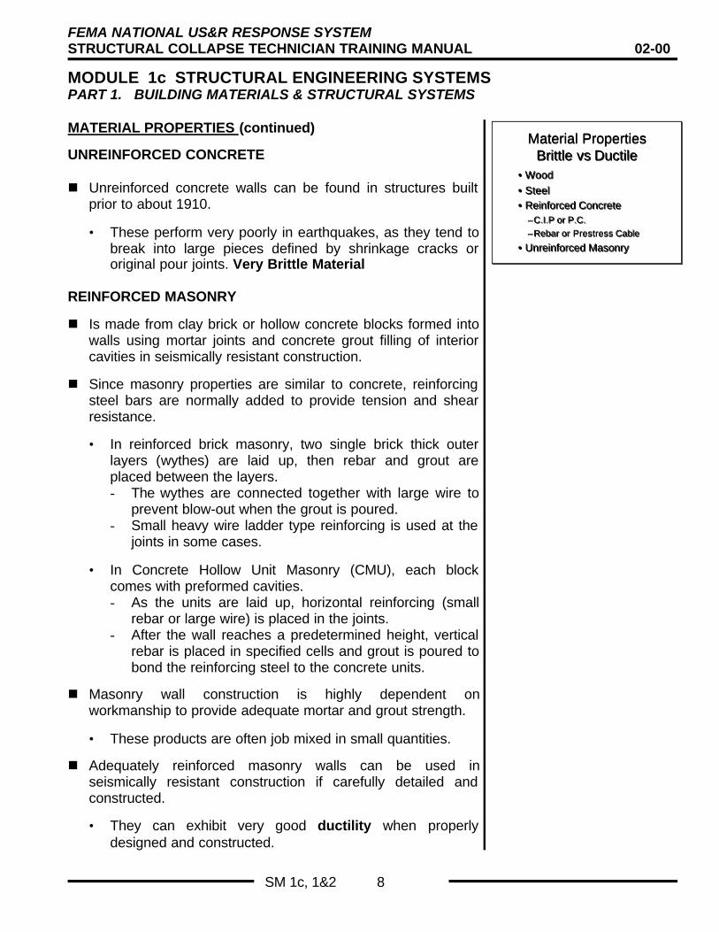
Material PropertiesBrittle vs Ductile
Material PropertiesBrittle vs Ductile
• Wood
• Steel• Reinforced Concrete
–C.I.P or P.C.
–Rebar or Prestress Cable
• Unreinforced Masonry
• Wood
• Steel• Reinforced Concrete
–C.I.P or P.C.
–Rebar or Prestress Cable
• Unreinforced Masonry

FEMA NATIONAL US&R RESPONSE SYSTEMSTRUCTURAL COLLAPSE TECHNICIAN TRAINING MANUAL 02-00
MODULE 1c STRUCTURAL ENGINEERING SYSTEMSPART 1. BUILDING MATERIALS & STRUCTURAL SYSTEMS
SM 1c, 1&2 6
MATERIAL PROPERTIES (continued)
STEEL
n Is tough, light, strong, ductile, and formable into any shape,but needs to be fireproofed.
• It starts to lose strength above 700 o Fahrenheit.
n It has almost magical property of ductility. That is, it can bestressed beyond it’s Elastic Limit and severely bent, but stillhave enough strength to resist failure.
• This makes it the ideal structural material, in that it giveswarning of collapse (has forgiveness).
n Steel is strong in Tension, Compression, and Shear
n Steel beams must be laterally braced so as not to buckleabout their weak axis, especially if the ductile performancerequired for earthquake resistance is expected.
n Steel-framed structures must be properly proportioned inorder to avoid the over loading of columns.
• As will be discussed later, diagonal bracing members canoverload columns during earthquakes if the columns arenot proportioned such that their strength exceeds the totalforce that can be delivered to them by the diagonals.
n Steel can be very efficiently connected by bolting or welding(older structures used rivets instead of bolts).
• Welded joints must be properly designed and constructedor they can lead to a brittle failure.
CONCRETE
n Is essentially cast rock, that is strong in compression but weakin tension and shear.
n Steel bars are cast into concrete to provide for the longitudinaltension force and enclosing type steel ties and stirrups areadded for confinement and shear resistance.
• Sufficient steel can be added to provide adequatetoughness for seismic resistance, enabling reinforcedconcrete to exhibit ductile properties similar to structuralsteel.
Material PropertiesBrittle vs Ductile
Material PropertiesBrittle vs Ductile
• Wood
• Steel• Reinforced Concrete
–C.I.P or P.C.
–Rebar or Prestress Cable
• Unreinforced Masonry
• Wood
• Steel• Reinforced Concrete
–C.I.P or P.C.
–Rebar or Prestress Cable
• Unreinforced Masonry

FEMA NATIONAL US&R RESPONSE SYSTEMSTRUCTURAL COLLAPSE TECHNICIAN TRAINING MANUAL 02-00
MODULE 1c STRUCTURAL ENGINEERING SYSTEMSPART 1. BUILDING MATERIALS & STRUCTURAL SYSTEMS
SM 1c, 1&2 7
MATERIAL PROPERTIES (continued)
CONCRETE (continued)
n Concrete can also be reinforced by adding high strength cableor bars that are pretensioned prior to their being loaded by thestructures weight (pre-stressed concrete).
n Structures of this type may be precast in a factory using Pre-tensioned reinforcing that is stretched in a form, then bondedto the concrete when it is cast.
n Another method is to place cables that are enclosed in plasticsleeves in the forms at a job site, pour the concrete, and thenstretch and Anchor the cables after the concrete has curedand achieved sufficient strength. (Post-Tensioned)
• In this case the cables are not bonded to the concrete, butonly anchored at the edges of the structure.
• These unbonded cables can cause difficulties whendealing with a damaged Post-Tensioned structure.
n Concrete shrinks, cracks, and creeps under normalcircumstances, and this normal behavior needs to bedifferentiated from the cracking and spalling that indicatesfailure.
n Concrete is easily connected together if cast in place, butmust be very competently connected together if it is precast.
• Since precast concrete members (especially prestressed,precast) can be very strong, the joints that connect thenmust be very tough (ductile) in order to resist the veryhigh dynamic forces generated by an earthquake.
n Properly reinforced concrete can provide seismically resistantconstruction if the reinforcing is proportioned such that theconfining tie, hoop and stirrups are sufficient to resist theshear that can be generated by the overall structuralconfiguration and longitudinal reinforcement.
• Wall like structures of cast in place and precast concretehave out performed frame type construction in mostearthquakes.
Material PropertiesBrittle vs Ductile
Material PropertiesBrittle vs Ductile
• Wood
• Steel• Reinforced Concrete
–C.I.P or P.C.
–Rebar or Prestress Cable
• Unreinforced Masonry
• Wood
• Steel• Reinforced Concrete
–C.I.P or P.C.
–Rebar or Prestress Cable
• Unreinforced Masonry
FEMA NATIONAL US&R RESPONSE SYSTEMSTRUCTURAL COLLAPSE TECHNICIAN TRAINING MANUAL 02-00
MODULE 1c STRUCTURAL ENGINEERING SYSTEMSPART 1. BUILDING MATERIALS & STRUCTURAL SYSTEMS
SM 1c, 1&2 8
MATERIAL PROPERTIES (continued)
UNREINFORCED CONCRETE
n Unreinforced concrete walls can be found in structures builtprior to about 1910.
• These perform very poorly in earthquakes, as they tend tobreak into large pieces defined by shrinkage cracks ororiginal pour joints. Very Brittle Material
REINFORCED MASONRY
n Is made from clay brick or hollow concrete blocks formed intowalls using mortar joints and concrete grout filling of interiorcavities in seismically resistant construction.
n Since masonry properties are similar to concrete, reinforcingsteel bars are normally added to provide tension and shearresistance.
• In reinforced brick masonry, two single brick thick outerlayers (wythes) are laid up, then rebar and grout areplaced between the layers.- The wythes are connected together with large wire to
prevent blow-out when the grout is poured.- Small heavy wire ladder type reinforcing is used at the
joints in some cases.
• In Concrete Hollow Unit Masonry (CMU), each blockcomes with preformed cavities.- As the units are laid up, horizontal reinforcing (small
rebar or large wire) is placed in the joints.- After the wall reaches a predetermined height, vertical
rebar is placed in specified cells and grout is poured tobond the reinforcing steel to the concrete units.
n Masonry wall construction is highly dependent onworkmanship to provide adequate mortar and grout strength.
• These products are often job mixed in small quantities.
n Adequately reinforced masonry walls can be used inseismically resistant construction if carefully detailed andconstructed.
• They can exhibit very good ductility when properlydesigned and constructed.
Material PropertiesBrittle vs Ductile
Material PropertiesBrittle vs Ductile
• Wood
• Steel• Reinforced Concrete
–C.I.P or P.C.
–Rebar or Prestress Cable
• Unreinforced Masonry
• Wood
• Steel• Reinforced Concrete
–C.I.P or P.C.
–Rebar or Prestress Cable
• Unreinforced Masonry

FEMA NATIONAL US&R RESPONSE SYSTEMSTRUCTURAL COLLAPSE TECHNICIAN TRAINING MANUAL 02-00
MODULE 1c STRUCTURAL ENGINEERING SYSTEMSPART 1. BUILDING MATERIALS & STRUCTURAL SYSTEMS
SM 1c, 1&2 9
MATERIAL PROPERTIES (continued)
UNREINFORCED MASONRY - URM
n Not currently built in seismic risk areas, but many structureswith URM walls still exist throughout the world.• This is a very Brittle material
n Walls were constructed with a thickness made from three ormore bricks being laid longways, side by side, for five or sixlayers high (courses) and then a layer was placed with thebricks at 90 degrees (header course), and so on.
n URM buildings date back to the late 1800s in California andback to the 1700s in other parts of the U.S. The strength ofthe bricks is generally higher outside of California.
n The strength and seismic performance of unreinforcedmasonry is highly dependent on the mortar strength.
• The shear strength of mortar can vary from 15 PSI to over150 PSI, and is determined by the proportion of lime toPortland cement and the workmanship.
• Lime produces a nice buttery mortar, but if too much isused a low strength will result.
• Lime can also be leached out of the mortar by water overtime.
n Decorative veneers are a special seismic problem.
• Veneers were often laid up with building paper betweenthem and the URM wall, and were anchored with wire orgalvanized ties.
• The ties normally corrode away within twenty years or so,leaving a heavy brick face, just waiting to peal off whensubjected to a lateral load.
• Masonry veneers are also found on the outside surfaces ofwood walls.
- There veneers are subject to the same anchorageproblems, as well as being dynamically incompatiblewith the flexibility of the wood walls.
n URM walls are made from native stone in many places in theworld, and have performed very poorly in earthquakes
Material PropertiesBrittle vs Ductile
Material PropertiesBrittle vs Ductile
• Wood
• Steel• Reinforced Concrete
–C.I.P or P.C.
–Rebar or Prestress Cable
• Unreinforced Masonry
• Wood
• Steel• Reinforced Concrete
–C.I.P or P.C.
–Rebar or Prestress Cable
• Unreinforced Masonry

FEMA NATIONAL US&R RESPONSE SYSTEMSTRUCTURAL COLLAPSE TECHNICIAN TRAINING MANUAL 02-00
MODULE 1c STRUCTURAL ENGINEERING SYSTEMSPART 1. BUILDING MATERIALS & STRUCTURAL SYSTEMS
SM 1c, 1&2 10
VERTICAL LOAD SYSTEMS
Structural members in these systems can be divided into twotypes, those that form horizontal (or sloped roof) planes andthose that provide the vertical support for these planes.
HORIZONTAL MEMBERS support floor and roof planes and arenormally loaded in bending such as:
Vertical Load SystemsVertical Load Systems
• Concept of gravity load path
• Loads must be transferred from Source toGround
• Top down approach
– Plumbing system analogy
• Framed and UnFramed
• Connections are particularly vulnerable
• Concept of gravity load path
• Loads must be transferred from Source toGround
• Top down approach
– Plumbing system analogy
• Framed and UnFramed
• Connections are particularly vulnerable
n Wood; rafters, joist, purlins, beams, girders.
n Steel; corrugated sheets (filled with concrete), joist, purlins,beams, girders.
n Reinforced concrete floor systems may be of many types. Allhave some relationship to the economy of providing adequatestructural depth with available forming materials.
Load Path ConceptLoad Path ConceptLoad Path Concept
n Precast concrete floors may contain, planks, cored slabs,single or double tees, beams and girders. Most modernsystems in California combine a cast-in-place overlay slab toprovide adequate interconnection of individual members andoverall planar stability.
n These individual members need to be interconnected to theirsupported planes in order to provide the lateral stability toresist the extreme fiber compression forces associated withbending, which occur on the top or bottom of the members.
Concrete Floor SystemsConcrete Floor Systems
Most of the reinforcing steel is concentratedin and over Beams and over Columns
TRUSSES are special vertical load resistant members that usegreater depth for structural efficiency, but require more positivelateral bracing of compression members.
n Trusses are usually made from wood and/or steel, althoughconcrete has been used for economy in some areas of theworld.
n Individual members are stressed in either tension orcompression, although stress may reverse in some membersdue to changes in live load (people, vehicles, and rain/snow).
n Compression members are normally governed by bucklingand tension members are normally governed by theirconnections.
Typical Truss ConfigurationsTypical Truss Configurations
• Tension in bottom chords• Compression in top chords• Small ten. or comp. In diagonals

FEMA NATIONAL US&R RESPONSE SYSTEMSTRUCTURAL COLLAPSE TECHNICIAN TRAINING MANUAL 02-00
MODULE 1c STRUCTURAL ENGINEERING SYSTEMSPART 1. BUILDING MATERIALS & STRUCTURAL SYSTEMS
SM 1c, 1&2 11
TRUSSES (continued)
n There have been many failures of wood trusses due toseasoning defects. Wood checks (splits) that occur near theends of tension members has lead to many pull-throughbolted connection failures. Overloads due to rain or snow canlead to sudden collapse, as a result of a compression memberbuckling or tension connection failure. The use of closelyspaced trusses with gang-nail connection plates, and thoseusing specially fabricated wood with steel pin connected barshave improved the reliability of wood trusses.
n Steel trusses have been fairly reliable , but they are alsosusceptible to sudden compression member failures, due totemporary overload, and loss of stability due to inadequatebracing of compression members
n Trusses present special problems when the shoring of ahazardous structure is being considered. The supportprovided by the shoring must be applied so as not to cause astability problem or overload of a small or inadequately bracedindividual truss member. (It’s usually a bad idea to shore atruss at the bottom chord.)
VERTICAL SUPPORT MEMBERS are normally configured asbearing walls or columns.
n In wood and light framed steel systems the bearing walls aremade using closely spaced columns (studs at 16-24" o.c.) thatmust be interconnected by a skin in order to provide thelateral stability that will allow the individual members to beloaded in compression without buckling.
n Concrete and masonry bearing walls are proportioned to carryheavy vertical loads depending on their height to thicknessratio.
n Individual column (posts) normally carry large compressionforces and may be made of wood, steel, or reinforcedconcrete. In all cases the load capacity is based on themembers slenderness ratio (l/r, l/d) as well as the adequacy ofthe connection between the column and the horizontalsystem.
n All vertical load systems need some system to provide forlateral stability (i.e., the proper alignment of vertical load path).These Lateral Load Systems need to be capable of resistinglateral forces that are at least two percent of the structure'sweight. (much more in Seismic Zones)
Typical Truss ConfigurationsTypical Truss Configurations
• Tension in bottom chords• Compression in top chords• Small ten. or comp. In diagonals
Load Path ConceptLoad Path ConceptLoad Path Concept

FEMA NATIONAL US&R RESPONSE SYSTEMSTRUCTURAL COLLAPSE TECHNICIAN TRAINING MANUAL 02-00
MODULE 1c STRUCTURAL ENGINEERING SYSTEMSPART 1. BUILDING MATERIALS & STRUCTURAL SYSTEMS
SM 1c, 1&2 12
LATERAL LOAD RESISTANT SYSTEMS
Most structures can be grouped into two basic types of lateralload systems: shear wall/box system and frame system.Buildings may contain sections of each type. Some buildingshave been designed with a dual system containing both types oflateral bracing in order to provide a more redundant system,which is highly desirable.
Lateral Load ResistingSystems
Lateral Load ResistingSystems
• Concept of load paths
• Pushover analogy• Connections are particularly vulnerable• Systems
– Box Buildings
– Moment Frames - (Ductile ?)
– Diagonally Braced Frames
• Concept of load paths• Pushover analogy• Connections are particularly vulnerable• Systems
– Box Buildings
– Moment Frames - (Ductile ?)
– Diagonally Braced Frames
SHEAR WALL/BOX BUILDINGS
n These are buildings with exterior walls that provide bearingstrength as well as seismic resistance. They may or may nothave interior, structural walls. Floors, flat or sloped roofplanes called diaphragms form the horizontal surfaces tocomplete the boxes, with the walls forming the sides.
n The typical action of a box structure subjected to the lateralloads is illustrated by the adjacent slide. Floor/roof planes actlike giant beams as stresses in tension and compression aregenerated at the edges while shear stresses are distributedthrough out the plane. The floor/roof planes (diaphragms),span horizontally between exterior (sometimes interior) wallswhich provide each horizontal plane with lateral support. Thewalls (shear) in turn are loaded by the floor diaphragm mustbe capable of resisting shear stresses plus bending stressescaused by overturning.
n Floor/roof diaphragms are made of plywood, diagonal woodsheathing, corrugated metal deck (with and without concretetopping), and concrete.
n Shear walls are made of plywood and solid wood sheathingover studs, concrete, and concrete block.
n In the very light weight wood systems the skin (sheathing)carries all of the lateral shear force, but is a minor verticalsupport member. In concrete and concrete block systems thevertical and lateral loads are carried by the relatively heavyreinforced concrete slab and bearing walls.
Box BuildingBox Building
Load

FEMA NATIONAL US&R RESPONSE SYSTEMSTRUCTURAL COLLAPSE TECHNICIAN TRAINING MANUAL 02-00
MODULE 1c STRUCTURAL ENGINEERING SYSTEMSPART 1. BUILDING MATERIALS & STRUCTURAL SYSTEMS
SM 1c, 1&2 13
LATERAL LOAD RESISTANT SYSTEMS (continued)
FRAME BUILDINGS MOMENT RESISTANT
n The walls for this type normally are constructed for enclosurepurposes only and may be of glass, light framing with non-structural covering (plaster veneer or brick/stone, finish wood),a combination of precast concrete and glass, etc. The verticalload is carried by large evenly spaced columns of steel orreinforced concrete.
n The floor and roof diaphragms are constructed as in the boxsystem, however, the stresses developed in the diaphragmsare usually smaller since they do not have to span as far.
n The lateral load resistance is provided by the interconnectionor large tough floor beams/girders and the columns. The"frame" made by the beams and columns is kept fromchanging into a parallelogram by making the connections asstrong as the members. Structural steel or well confinedheavily reinforced concrete are used today for these momentresistant frames.
n Structural toughness- the ability to repeatedly sustainreversible stresses in the inelastic range without significantdegradation is essential for a moment resistant frame. Mostconcrete frames built prior to 1965 in California (and otherseismic zones with similar building codes) were notconstructed with much structural toughness. Structural steelframes have out performed concrete frames in the past.There were examples of lightly connected steel frames thatsurvived the San Francisco 1906 earthquake, however, theywere susceptible to fire damage.
n Tall buildings with moment frames may generate significanttension and compression forces in the exterior and or cornercolumns. High tensions can be very detrimental to olderconcrete frames, since severe cracking can result incatastrophic failures when the loading is reversed and themember is also required to resist bending. High compressionforces in steel frames can cause buckling of tube or wideflange columns.
Moment FrameMoment Frame
Load

FEMA NATIONAL US&R RESPONSE SYSTEMSTRUCTURAL COLLAPSE TECHNICIAN TRAINING MANUAL 02-00
MODULE 1c STRUCTURAL ENGINEERING SYSTEMSPART 1. BUILDING MATERIALS & STRUCTURAL SYSTEMS
SM 1c, 1&2 14
LATERAL LOAD RESISTANT SYSTEMS (continued)
FRAME BUILDINGS MOMENT RESISTANT (continued)
n Modern building codes require that the columns be strongerthan the sum of the connecting beams at any story, in orderthat when inelastic action occurs it will form plastic hinges inthe beams, not the columns. Since modern steel momentframes are connected by welding, good workmanship iscritical. Visual inspection and ultrasonic testing is normallyrequired to assure quality control.
n Moment resistant frames can be used in combination withconcrete shear walls to provide a dual system.
n Older, pre-1960, steel moment frames may be covered withcast-in-place concrete fireproofing. (Important identificationinfo.)
Moment FrameMoment Frame
Load
FRAME BUILDINGS DIAGONALLY BRACED
n These systems are constructed similar to moment resistantframe structures. Their lateral load resistance is provided byadding diagonal members between columns to prevent lateralracking. Alternately reversing tension and compression forcesare generated in the diagonal members which are usuallymade of structural steel, although reinforced concrete hasbeen used (especially in Central and South America).
n Diagonal members should be able to resist both tension andcompression, since the whipping action of slender rod cross-bracing can allow too much distortion. An exception is thatlight, steel frame, industrial buildings have performedreasonably well with slender rod cross-bracing, sincecorrugated metal finishes are quite flexible.
n The columns in diagonally braced frames need to beproportioned so that they are stronger than the tensioncapacity of the braces that are connected to them. This is inorder to assure that failure will not occur in the columns, andhas only been required in recent building codes.
n Diagonal members are normally made from double angles ortube sections, and connections must be carefully detailed andbuilt in order to prevent local buckling and/or other joint failure.
Diagonal Braced FrameDiagonal Braced FrameDiagonal Braced Frame
Load

FEMA NATIONAL US&R RESPONSE SYSTEMSTRUCTURAL COLLAPSE TECHNICIAN TRAINING MANUAL 02-00
MODULE 1c STRUCTURAL ENGINEERING SYSTEMSPART 1. BUILDING MATERIALS & STRUCTURAL SYSTEMS
SM 1c, 1&2 15
LATERAL LOAD RESISTANT SYSTEMS (continued)
FRAME BUILDINGS DIAGONALLY BRACED (continued)
n Diagonal braced frames have been used in combination withmoment resistant frames to provide a highly desirable, dualsystem. They also are configured as eccentric braces within amoment frame bay to provide a bracing system that combinesthe toughness of moment frame with the rigidity of bracedframe.
REDUNDANCY
n Especially in Seismic Zones, it is important for the LateralLoad System to possess some degree of Redundancy.
n Redundancy in a structure means that there is more than onepath of resistance for Lateral Forces.
n This can be achieved by having more than one ShearwallPanel or more than one Diagonal Brace in every line ofresistance, or
n This can be achieved by having a Moment Resistant Framewith many columns and beams, all with ductile connections, or
n This can be achieved by having a Dual System, likeShearwalls plus a Moment Resistant Frame
Diagonal Braced FrameDiagonal Braced FrameDiagonal Braced Frame
Load
RedundancyRedundancyRedundancy• Multi - Elements
(at least 2 in every line of resistance)– Box Buildings
– Diagonal Braced Frames
• Majority of Connections– Moment Frames
• Dual Systems• Collapse Preventers
•• Multi - ElementsMulti - Elements(at least 2 in every line of resistance)(at least 2 in every line of resistance)–– Box BuildingsBox Buildings
–– Diagonal Braced FramesDiagonal Braced Frames
•• Majority of ConnectionsMajority of Connections–– Moment FramesMoment Frames
•• Dual SystemsDual Systems
•• Collapse PreventersCollapse Preventers
SUSPENSION / TENSION STRUCTURES
n Are not commonly used in building structures. These are veryefficient structures that require significant height (cable drape)to span great spaces.
n Earthquake damaged, reinforced concrete slabs often formtension like structures, after failure of a vertical support. (asshown in adjacent slide) This will cause unplanned tensionforces in the remainder of the structure, which may causelean-over of the remaining walls etc. However, this action canprevent complete collapse, but leaves a condition that isdifficult to assess. The slabs may be hanging on reinforcingsteel with unknown and/or unreliable embedment.
Tension Structure RedundancyTension Structure Redundancy
Suspension Bridge
Partly Collapsed Building
Catenary
Catenary

FEMA NATIONAL US&R RESPONSE SYSTEMSTRUCTURAL COLLAPSE TECHNICIAN TRAINING MANUAL 02-00
MODULE 1c STRUCTURAL ENGINEERING SYSTEMSPART 2. COLLAPSE PATTERNS
SM 1c, 1&2 16
The Objectives for this section are listed in adjacent slides,and we will discuss the folowing:
n The types of forces that load structuresn The method that is used to classify structures, and the types
of problems that buildings have experienced in the past.n The Collapse Patterns that have occurred that will give us
some insight as to how structures will behave in the future.
TERMINAL OBJECTIVESTERMINAL OBJECTIVES
•• The Student shall understand the howThe Student shall understand the howbuilding structures can be separated intobuilding structures can be separated intospecific types that exhibit unique collapsespecific types that exhibit unique collapsepatterns when subjected to extreme forcespatterns when subjected to extreme forcesdue to Earthquake Wind , and Explosionsdue to Earthquake Wind , and Explosions
•• The Student shall be able to recognize theirThe Student shall be able to recognize theirunique Collapse Patternsunique Collapse Patterns
EARTHQUAKE BASICSEarthquakes are catastrophic events that occur mostly at theboundaries of portions of the Earth’s crust called Tectonic Plates.When movement occurs in these regions, along Faults, wavesare generated at the Earth’s surface that can produce verydestructive effects. The things that US&R forces NEED to knowabout these events are summarized in the following.
EARTHQUAKE MAGNITUDE
ENABLING OBJECTIVESENABLING OBJECTIVES
•• Understand the extreme environmental andUnderstand the extreme environmental andman caused forces that effect structures.man caused forces that effect structures.
•• Define and Understand how buildings areDefine and Understand how buildings areclassified by engineers based on theirclassified by engineers based on theirConstruction Materials and Lateral LoadConstruction Materials and Lateral LoadResisting Systems.Resisting Systems.
•• Discuss the most common Collapse PatternsDiscuss the most common Collapse Patternsthat have been observed as a result ofthat have been observed as a result ofEarthquakes, Windstorms, and ExplosionsEarthquakes, Windstorms, and Explosions
Is a way of measuring the total energy released by a quake,which could also relate to the total damage done (all else beingequal). If we compare the two quakes illustrated (Large Quakeand Great Quake) at the right, we can demonstrate what thismeans to US&R. For a bigger Magnitude the following can besaid:
n The maximum intensity of the shaking may be similarn The duration of the shaking (at the fault) is longer.
Earthquake BasicsEarthquake Basics
•• Extent of damage is determined byExtent of damage is determined by–– type of shaking that occurs at sitetype of shaking that occurs at site
–– coupled with the structures responsecoupled with the structures response
•• Magnitude (energy release)Magnitude (energy release)–– determines POTENTIAL number ofdetermines POTENTIAL number of
effected structureseffected structures
•• AftershocksAftershocks–– Earthquakes are unique type of DisasterEarthquakes are unique type of Disaster
–– just keeps on givingjust keeps on giving
n The length of the fault break is longer (directly related toduration)
n The area of the Earth that will be effected by intense shakingis MUCH larger, and, therefore, the potential for greater US&Rinvolvement is MUCH larger
AFTERSHOCKSThese smaller quakes occur after ALL large Earthquakes. Theyare usually most intense in size and number within the first week
Plan of Large Earthquake - M 7Plan of Large Earthquake - M 7
Causes major damageif Fault is within city
30kmFault Break
Duration 15 secEff peak accel .5G
Of the original quake.
n They can cause the very significant re-shaking of damagedstructures which makes earthquake induced disasters morehazardous to US&R than most others.
n A number of moderate quakes (6+ magnitude) have hadaftershocks that were very similar in size to the original quake.
Plan of Great Earthquake M 8+Plan of Great Earthquake M 8+
250km
Fault Break
Duration 60 secEff Peak Accel .6G
Fault rupture speed is 2 to 3Fault rupture speed is 2 to 3 kms kms
Total energy release is 30to 100 times large Quake

FEMA NATIONAL US&R RESPONSE SYSTEMSTRUCTURAL COLLAPSE TECHNICIAN TRAINING MANUAL 02-00
MODULE 1c STRUCTURAL ENGINEERING SYSTEMSPART 2. COLLAPSE PATTERNS
SM 1c, 1&2 17
EARTHQUAKE BASICS (continued)
AFTERSHOCKS (continued)
n Arrays of strong motion instruments can be set out after anearthquake and data from aftershocks will allow the mappingof the fault surface. These instruments can also be coupledwith a warning system to notify US&R TF prior the effect beingfelt at a building site – discussed in Monitoring.
n Aftershocks diminish in intensity and number with time. Theygenerally follow a pattern of there being at least one large(within one Richter Magnitude) aftershock, at least ten lesser(within two Richter Magnitude) aftershocks, one hundredwithin three, and so on
AftershocksAftershocks
• Smaller quakes that occur on same faultas original quake. Minor fault adjustments
• Occur after most quakes regardless ofsize of original shock
• Some have been almost as large asoriginal. (in range of M 6)
• Will occur during US&R Ops since aremost prevalent in first week.
n The Loma Prieta earthquake had many aftershocks, but thelargest was only magnitude 5.0 with the original quake beingmagnitude 7.1 or so.
n Wood, masonry, and concrete structures have collapsedduring aftershocks, (even during one of the Loma Prietarelative moderate 5.0 aftershocks).
How Many Aftershocks ?How Many Aftershocks ?
•• USGS - Rule of ThumbUSGS - Rule of Thumb–– For every single decrease in magnitude,For every single decrease in magnitude,
get 10 fold increase in numberget 10 fold increase in number
•• If original quake is M 7If original quake is M 7–– 1 or so aftershock in range of M 61 or so aftershock in range of M 6–– 10 “ “ “ “ 510 “ “ “ “ 5
–– 100 “ “ “ “ 4100 “ “ “ “ 4
–– 1000 “ 1000 “ “ “ “ 3 “ “ “ 3
BASIC STRUCTURAL LOADING
EARTHQUAKESn Some of the most destructive effects caused by earthquake
shaking are those that produce lateral loads in a structure.The input shaking causes the foundation of a building tooscillate back and forth in a more or less horizontal plane.The building mass has inertia and wants to remain where it isand, therefore, lateral forces are exerted on the mass in orderto bring it along with the foundation. This dynamic action canbe simplified (in an upside down way) as a group of horizontalforces that are applied to the structure in proportion to itsmass, and to the height of the mass above the ground.
n In multi-story buildings with floors of equal weight andrelatively light walls, the loading is further simplified as agroup of loads, each being applied at a floor line, and eachbeing greater than the one below in a triangular distribution.Seismically resistant structures are designed to resist theselateral forces through inelastic action and must, therefore, bedetailed accordingly. These loads are often expressed interms of a percent of gravity weight, and can vary from a fewpercent to near fifty percent of gravity weight.
1989 Loma Prieta Aftershocks1989 Loma Prieta Aftershocks
Days after original shockDays after original shock
Mag
nitu
de
Mag
nitu
de
Earthquake LoadingEarthquake Loading
8s

FEMA NATIONAL US&R RESPONSE SYSTEMSTRUCTURAL COLLAPSE TECHNICIAN TRAINING MANUAL 02-00
MODULE 1c STRUCTURAL ENGINEERING SYSTEMSPART 2. COLLAPSE PATTERNS
SM 1c, 1&2 18
BASIC STRUCTURAL LOADING (continued)
EARTHQUAKES (continued)
n There are also vertical loads generated in a structure byearthquake shaking, but as mentioned previously, theseforces rarely overload the vertical load resisting system.Earthquake induced vertical forces have caused damage toheavy concrete structures with high dead load compared todesign live load. These vertical forces also increase thechance of collapse in concrete frame buildings due to eitherincreased or decreased compression forces in the columns.(Increased compression that overloads columns or decreasedcompression that reduces column bending strength.)
WIND STORMS
n Forces are generated on the exterior of the building based onits height, local ground surface roughness (hills, trees, otherbuildings) and the square of the wind velocity. The weight ofthe building, unlike the earthquake condition, has little effecton wind forces, but is helpful in resisting uplift.
n Unless the structure is penetrated all the forces are applied tothe exterior surfaces of the building, as contrasted toearthquakes, where as an example both exterior and interiorwalls are loaded proportionally to their weight.
n Wind pressures act inward on the windward side of a buildingand outward on most other sides and most roof surfaces.Special concentrations of outward force, due to aerodynamiclift, occur at building corners and roof edges, especiallyoverhangs.
n The overall structure must be designed for the sum of alllateral and uplift pressures and individual parts must bedesigned to resist the outward and inward pressureconcentrations, and must be connected to supportingmembers (beams, columns, walls, foundation) to form acontinuous resistance path. Forces are also generated onstructures by airborne missiles that vary in size from roofinggravel to entire sections of roofs.
Earthquake LoadingEarthquake Loading
8s
Wind LoadingWind Loading
6s

FEMA NATIONAL US&R RESPONSE SYSTEMSTRUCTURAL COLLAPSE TECHNICIAN TRAINING MANUAL 02-00
MODULE 1c STRUCTURAL ENGINEERING SYSTEMSPART 2. COLLAPSE PATTERNS
SM 1c, 1&2 19
BASIC STRUCTURAL LOADING (continued)
EXPLOSION
n They occur when a solid or concentrated gas is transformedinto a large volume of hot gases in a fraction of a second.
n In the case of High Explosives, detonation (conversion ofenergy) occurs at a very high rate (as high as 4 miles /sec),while Low Explosives (such as gunpowder) undergo rapidburning at the rate of about 900 ft./sec. The resulting rapidrelease of energy consists of sound (bang), heat and light(fireball) and a shock wave that propagates, radially outwardfrom the source at subsonic speeds for most Low Explosivesand supersonic speeds for High Explosives.
n It is the shock wave, consisting of highly compressed particlesof air that causes most of the damage to structures.
n When natural gas explosions occur within structures, gaspressures can build up within confined spaces causingextensive damage. In all explosions, large, weak and/orlightly attached wall, floor, and roof surfaces may be blownaway. The columns and beams in steel frame structures maysurvive a blast, but their stability maybe be compromised bythe removal of their bracing elements (floor diaphragms,shearwalls). In large explosions concrete slabs, walls andeven columns may be blown away, leading to conditions thatwill produce progressive collapse as illustrated in the slide atthe top of the page. In 1960 a progressive collapse startedwhen a natural gas explosion caused the collapse of anexterior wall on the 18th floor of a 22-story building. The forceof falling debris from floors 19 to the roof then caused theremaining floors to collapse in that section of the building.
Interior Explosion LoadingInterior Explosion Loading
3s
Exterior Explosion LoadingExterior Explosion Loading
overpressure
overpressure
overpressure
drag
reflectedpressure
sphericalshockwave
stand-off1s
n In the case of an exterior explosion from a bomb, the shockwave is initially reflected and amplified by the building faceand then penetrates thru openings, subjecting floor and wallsurfaces to great pressure. Diffraction occurs as the shockpropagates around corners, creating areas of amplificationand reduction in pressure. Finally the entire building isengulfed by the shock wave, subjecting all building surfaces tothe over-pressure.
n A secondary effect of an air-blast is a very high velocity windthat propels the debris (becoming deadly missiles), and inaddition a high intensity, short duration ground shaking(earthquake) may be induced.
Exterior Explosion LoadingExterior Explosion Loading
A
B
C
Exterior walls,columns & windows
Roof & Floor slabs
Frame
Ground shock 1s

FEMA NATIONAL US&R RESPONSE SYSTEMSTRUCTURAL COLLAPSE TECHNICIAN TRAINING MANUAL 02-00
MODULE 1c STRUCTURAL ENGINEERING SYSTEMSPART 2. COLLAPSE PATTERNS
SM 1c, 1&2 20
BASIC STRUCTURAL LOADING (continued)
EXPLOSION (continued)
n In very large explosions at close proximity to reinforcedconcrete surfaces, the effect can be so severe that theconcrete is locally disintegrated and separated away from thereinforcing steel. Lighter wood, steel frame, and even precastconcrete buildings can be leveled by explosions as the walland floor/roof planes are blown away leading to an overallloss of stability.
FIRE
n Wood or metal roof/floors often collapse due to burn-throughand can pull exterior masonry or concrete walls in or leavethem standing in an unbraced condition.
n A steel structure left standing after a fire can have significantlyreduced strength due to loss of the original heat treatment.
n A remaining concrete structure can be damaged due tospalling and shearwalls can be cracked due to expansion offloors.
Loading Caused by FireLoading Caused by Fire
•• Burnout of Wood Roof can lead toBurnout of Wood Roof can lead todangerous unbraced walls 1sdangerous unbraced walls 1s
•• Fire in Steel Building can lead to damageFire in Steel Building can lead to damagedue to expansion 1sdue to expansion 1s
•• Heat from Burned Wood ApartmentHeat from Burned Wood Apartmentcaused Expansion Damage to RMcaused Expansion Damage to RMshearwalls in Basement Garage 2sshearwalls in Basement Garage 2s
FLOOD
n Forces are generated on buildings due to hydrostatic lateraland lifting pressure, hydrodynamic forces, and debris impacts.
n Hydrostatic pressures can highly load foundation andbasement walls and lift structures, when water level is notequalized between exterior and interior spaces.
Typical Flood LoadingTypical Flood Loading
1s
n River and ocean currents will load frontal and side walls thatare submerged, and ocean waves and step-up flows canproduce pressures as high as 1000 PSF.
n Debris varying in size from floating wood pieces to floatingstructures can impact a building causing anything from brokenwindows to a total collapse.
Flood Loading in PlanFlood Loading in Plan

FEMA NATIONAL US&R RESPONSE SYSTEMSTRUCTURAL COLLAPSE TECHNICIAN TRAINING MANUAL 02-00
MODULE 1c STRUCTURAL ENGINEERING SYSTEMSPART 2. COLLAPSE PATTERNS
SM 1c, 1&2 21
BASIC STRUCTURAL LOADING (continued)
CONSTRUCTION BRACING, URBAN DECAY, OVERLOAD
n These sudden, collapses usually occur due to gravity loadingwhen a vertical support is either inadequate, overloaded bysnow, overloaded due to plugged roof drain, or reduced incapacity due to age, corrosion, or non-engineered alteration.
n Failures of this type occur all too frequently, but most ofteneffect only one structure at a time. In some cases veryhazardous conditions have been left standing in this type ofcollapse (i.e., multi-story URM walls left unsupported whenwood floors pancaked).
Construction Bracing, OverloadConstruction Bracing, Overload
4s
VEHICLE IMPACT LOADING
n Structures have been severely damaged and set on fire byvehicle impacts.
n 1989 train derailment in California lead to a well organized,integrated response that was successful in saving a victim inwhat was originally perceived as an un-survivable condition.
Vehicle Impact Loading• Planes, Trains, Boats, & Highway
Vehicles have impacted Structures• Collapse and often Fires have resulted
• 1989 Train Derailment in So Cal buriedseveral homes.– CAL OES organized and directed a
successful deployment of K9 Search to aidlocal Fire/Rescue forces
– Demonstrated Value of Integrated US&R2s
ATC-21 NOMENCLATURE
ATC-21, Rapid Visual Screening of Buildings For PotentialSeismic Hazards was funded by FEMA and written by AppliedTechnology Council (ATC) in 1988. ATC was created by theStructural Engineers Assn. Of California to develop and manageresearch and other projects that add to the body of knowledgeregarding Structures.
n ATC-21 defined twelve specific building types, based on howthey respond to Earthquakes.
Building types - ATC-21-1Building types - ATC-21-1
• W Wood buildings of all types• S1 Steel moment resisting frames• S2 Braced steel frames• S3 Light metal buildings
• S4 Steel frames w/C I P conc walls
• They are listed in the slides at right, and are defined by thetype of material used in construction as well as the type ofLateral Load Resistant System employed.
• As an example for Concrete Construction, we have a C1Type that has a Moment Resistant Frame, a C2 Type thatis a Box Building with Shear Walls for lateral resistance,and C3 Type to cover the many buildings that have aMoment Resistant Frame with some sort of masonry infillwalls for fireproof exterior enclosure
Building types - ATC-21-1Building types - ATC-21-1
• C1 Concrete moment resisting frames• C2 Concrete shear wall buildings• C3/S5 Conc/steel frame w/urm infill walls• TU Tilt-up concrete wall building
• PC2 Precast concrete frame buildings• RM Reinforced masonry buildings• URM Unreinforced masonry building

FEMA NATIONAL US&R RESPONSE SYSTEMSTRUCTURAL COLLAPSE TECHNICIAN TRAINING MANUAL 02-00
MODULE 1c STRUCTURAL ENGINEERING SYSTEMSPART 2. COLLAPSE PATTERNS
SM 1c, 1&2 22
ATC-21 NOMENCLATURE (continued)
n The FEMA US&R Response System has adopted the ATC-21nomenclature for use in identifying damaged structures.
• It has be used in this Training Manual and for the StructureTriage and Structure/Hazard Evaluation Forms.
n Other systems, such as given in the Building Code and inFrancis Brannigan’s Building Construction for the Fire Serviceare based on resistance and response to Fire.
• They are not as specific enough to differentiate to beusefull in describing structural response to Earthquake andthe other destructive forces encountered in US&R.
• The slide at the right gives a comparison between theBuilding Types listed by Brannigan and ATC-21
PROBLEM BUILDINGS
The adjacent slide lists some of the building types that have beensusceptible to Quake and/or Wind damage in the past. As onecan see the list includes most all structural types.
n S2, C1, C3/S5, TU, PC2 and URM are expected to be mostsusceptible to earthquake damage thruout the U.S.
n Wood residential structures have also experienced a largenumber of failures in California, since they are, by far, themost prevalent building type. There is potential for entrapmentof victims in multi-story wood structures.
• Poorly tied wood structures are also very vulnerable toWind Damage
n Type S3 is listed since it is very susceptible to damage bywind.
n Many S1 structures experienced cracks in their welded con-nections during the Northridge (L.A.) quake, which is of greatconcern to design profession.
• None of these buildings were damaged to an extent thatwould cause collapse, but they may become a problem infuture quakes.
Compare Brannigan to ATCCompare Brannigan to ATC
•• ATC has more categories and relates toATC has more categories and relates tohow structures respond to Earthquakes.how structures respond to Earthquakes.
•• Brannigan relates to how structures areBrannigan relates to how structures areeffected by Fireeffected by Fire
–– Wood Construction = WWood Construction = W
–– Ordinary Construction = URM, RM, TUOrdinary Construction = URM, RM, TU
–– Steel Construction = S1, S2, S3, S4, S5Steel Construction = S1, S2, S3, S4, S5
–– Concrete Construction = C1, C2, C3Concrete Construction = C1, C2, C3
–– High Raise High Raise ConstrConstr. = S1, S2, C1, C2, C3. = S1, S2, C1, C2, C3
–– Garden Apartments = WGarden Apartments = W
Problem BuildingsProblem Buildings
•• W 1 to 3 story houses & 2 to 4 storyW 1 to 3 story houses & 2 to 4 story apartments (especially pre 1970) apartments (especially pre 1970)•• S1 Frames w/brittle weldedS1 Frames w/brittle welded conns conns•• S2 Frames where column capacity isS2 Frames where column capacity is less than capacity of diag braces less than capacity of diag braces•• S3 Light structure vulnerable to WindS3 Light structure vulnerable to Wind•• C1/C3 Pre 1971 bldgs (C1/C3 Pre 1971 bldgs (especespec pre 1941) pre 1941)•• PC2/TU Factory builtPC2/TU Factory built precast precast & tilt-up wall & tilt-up wall•• URM 1 to 8 story (most 3 story & less)URM 1 to 8 story (most 3 story & less) + steel & conc frames w/URM infill + steel & conc frames w/URM infill•• Others Irregular - soft story, open frontOthers Irregular - soft story, open front

FEMA NATIONAL US&R RESPONSE SYSTEMSTRUCTURAL COLLAPSE TECHNICIAN TRAINING MANUAL 02-00
MODULE 1c STRUCTURAL ENGINEERING SYSTEMSPART 2. COLLAPSE PATTERNS
SM 1c, 1&2 23
BUILDING DESCRIPTIONS & PROBLEMS
WOOD FRAME BUILDINGS W
These structures can vary from 1 to 4 stories and contain fromone to over 100 living units.
n The principle weakness may be in lateral strength of walls, orinterconnection of structure especially at the foundation.
n Common problems in strong earthquakes are:
• Walls that are weakened by too many openings becomeracked (rectangles become parallelograms).
- This can cause a significant offset of one floor fromanother and in severe cases collapse has occurred.
• Relatively modern 2 and 3 story, wood apartment buildingsmay have walls that are braced using only plaster/gypsumboard, let-in bracing, or inadequately designed plywood.
- These structures may experience brittle, first storyfailures, especially when upper story walls do not alignwith those in the lower story.
- These structures are especially vulnerable to Quakedamage when light weight concrete fill has been addedto provide better sound control. (greater mass meansgreater Quake force is generated)
• Wood houses with crawl spaces can shift or slide off theirfoundations.
• Masonry chimneys can crack and fall off or into thestructure.
• Masonry veneers can fall off walls and shower adjacentareas with potentially lethal objects.
• Structures can separate at offsets in floor/roof levels (suchas porches and split level houses).
• There is a great danger of fire in these structures due tothe presence of so much fuel.
Wood Houses W
2s
Wood Frame Apartments W
3s

FEMA NATIONAL US&R RESPONSE SYSTEMSTRUCTURAL COLLAPSE TECHNICIAN TRAINING MANUAL 02-00
MODULE 1c STRUCTURAL ENGINEERING SYSTEMSPART 2. COLLAPSE PATTERNS
SM 1c, 1&2 24
WOOD FRAME BUILDINGS W (continued)
FEMA NATIONAL US&R RESPONSE SYSTEMSTRUCTURAL COLLAPSE TECHNICIAN TRAINING MANUAL 02-00
MODULE 1c STRUCTURAL ENGINEERING SYSTEMSPART 2. COLLAPSE PATTERNS
SM 1c, 1&2 25
BUILDING DESCRIPTIONS & PROBLEMS (continued)
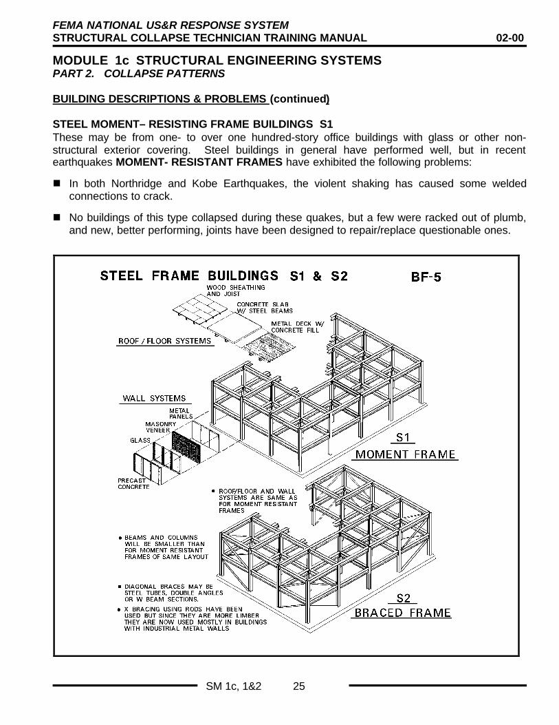
STEEL MOMENT– RESISTING FRAME BUILDINGS S1These may be from one- to over one hundred-story office buildings with glass or other non-structural exterior covering. Steel buildings in general have performed well, but in recentearthquakes MOMENT- RESISTANT FRAMES have exhibited the following problems:
n In both Northridge and Kobe Earthquakes, the violent shaking has caused some weldedconnections to crack.
n No buildings of this type collapsed during these quakes, but a few were racked out of plumb,and new, better performing, joints have been designed to repair/replace questionable ones.

FEMA NATIONAL US&R RESPONSE SYSTEMSTRUCTURAL COLLAPSE TECHNICIAN TRAINING MANUAL 02-00
MODULE 1c STRUCTURAL ENGINEERING SYSTEMSPART 2. COLLAPSE PATTERNS
SM 1c, 1&2 26
BUILDING DESCRIPTIONS & PROBLEMS (continued)
STEEL MOMENT– RESISTING FRAME BUILDINGS – S1(continued)n Since these connections are what gives Moment Resisting
Frames their lateral resistance, it is possible that a futureGreat Earthquake (M 7.5 to 8.5) could cause a catastrophiccollapse., especially if the following occurred:• Shaking lasts for more than 30 seconds
• A structure has little redundancy (only a few columns withwelded joints), and the joints are the types that can crackand fail.
DIAGONALLY BRACED STEEL FRAMES - S2These may be from one- to twenty-story office buildings withglass or other non-structural exterior covering. Steel buildings ingeneral have performed well, but those with diagonal bracinghave had the following problems:
n Buildings that contain slender rod cross bracing may haveexcessive distortion (story drift) which can lead to shedding orsignificant damage to brittle, finish materials such as glass,masonry veneer, or precast concrete panels. Whipping actionhas caused some slender cross braces to break.
n When the braces/columns are not properly proportioned,especially in taller frames, the great tension strength of thebraces can cause compression (buckling) failure of columns.
n This effect is attributed to the catastrophic failure of the PinoSuarez, 20 story tower in Mexico City in 1985.
n When tube type members are used for diagonals, suddenlocal crippling at cross-section corners has resulted. This canoccur when cold rolled tubes are used, since high stressesare originally induced during forming.
n Inadequate detailing or workmanship at connections hascaused local failures, such as buckling of connection platesand roll over of beams. Although collapse has not resultedfrom these failures, significant non-structural damage hasoccurred.
Steel Moment Frame S1
4s
Steel Diag. Braced Frame S2
3s

FEMA NATIONAL US&R RESPONSE SYSTEMSTRUCTURAL COLLAPSE TECHNICIAN TRAINING MANUAL 02-00
MODULE 1c STRUCTURAL ENGINEERING SYSTEMSPART 2. COLLAPSE PATTERNS
SM 1c, 1&2 27
BUILDING DESCRIPTIONS & PROBLEMS (continued)
LIGHT METAL BUILDINGS - S3
These are normally one story pre-engineered buildings, sheathed with metal siding and roofing.These structures have been damaged during earthquakes due to poor connections and fielderrors such as incomplete welding of joints, however most respond well to quakes due to theirlack of mass and abundance of flexibility. During strong windstorms, however, LIGHT METALSTRUCTURES have exhibited the following problems:
n Building walls and roof loose sheathing, purlins and girts that were braced by the sheathingwill then buckle, often leading to progressive, buckling collapse of entire structure.

FEMA NATIONAL US&R RESPONSE SYSTEMSTRUCTURAL COLLAPSE TECHNICIAN TRAINING MANUAL 02-00
MODULE 1c STRUCTURAL ENGINEERING SYSTEMSPART 2. COLLAPSE PATTERNS
SM 1c, 1&2 28
BUILDING DESCRIPTIONS & PROBLEMS (continued)
LIGHT METAL BUILDINGS - S3 (continued)
n Doors and windows are blown in leading to greatly increasedoutward pressures on leeward wall and roof, followed byshedding of sheathing, and in most severe cases, progressivecollapse.
n Tie-rod bracing can be broken or stretched by whippingaction. Also, rod end connections can fail by pullout, pryingaction, etc.
n Lower chord bracing at end walls can buckle due to windpressure on wall.
n Since these structures have little redundancy, performance isusually governed by "WEAKEST LINK" behavior (failure ofone element can lead to progressive/domino type collapse).
CONCRETE FRAME BUILDINGS - C1, C3Older frames are from one to thirteen stories high, and may haveURM infill walls. Older frames in California had thin concrete infillwalls on property lines in some cases. The most hazardousconfigurations include soft (high, open) first stories, open frontbuildings (typical of retail one and two story), and corner buildings(torsion problems). The common earthquake problems are:
n Columns break at intersections with floor beam. Inadequaterebar and ties don't confine the concrete when subjected tohigh shear and tension stresses. Failures may be driven bystrong P-Delta effect.
n Short columns in exterior walls get high shear and tensionstresses focused into them by surrounding massive concrete.
n Bending and punching shear failure at inter-sections of flatslabs (waffle etc.) and columns.
n URM infill can fall off, often pop out of surrounding frames.Also, URM infill can cause columns to shear off at floor line ortop of URM.
n Weak concrete and poor construction can make all aboveconditions worse and more likely to lead to larger collapse.
Light Metal BuildingS3
2s
Concrete Moment Frames C1
2s

FEMA NATIONAL US&R RESPONSE SYSTEMSTRUCTURAL COLLAPSE TECHNICIAN TRAINING MANUAL 02-00
MODULE 1c STRUCTURAL ENGINEERING SYSTEMSPART 2. COLLAPSE PATTERNS
SM 1c, 1&2 29
BUILDING DESCRIPTIONS & PROBLEMS (continued)
CONCRETE FRAME BUILDINGS C1, C3 (continued)

FEMA NATIONAL US&R RESPONSE SYSTEMSTRUCTURAL COLLAPSE TECHNICIAN TRAINING MANUAL 02-00
MODULE 1c STRUCTURAL ENGINEERING SYSTEMSPART 2. COLLAPSE PATTERNS
SM 1c, 1&2 30
BUILDING DESCRIPTIONS & PROBLEMS (continued)
CONCRETE SHEARWALL BUILDINGS - C2 are from one to thirteen stories high with walls onall four sides and/or within the structure as corridor/stair or other divisions between spaces. Wallsmay have openings "punched in" as doors or windows, but in more modern buildings, theopenings may be in groups that are placed between solid wall sections. These buildings rarelycollapse in earthquakes but damage can occur, such as:n X-cracking of wall sections between punched-in openings.
n Severe cracking of shallow wall/floor header sections that frame between solid wall sections.
n Severe cracking or collapse of columns that occur in "soft stories" of otherwise uniformly stiffshearwall buildings (soft first-story, etc.).

FEMA NATIONAL US&R RESPONSE SYSTEMSTRUCTURAL COLLAPSE TECHNICIAN TRAINING MANUAL 02-00
MODULE 1c STRUCTURAL ENGINEERING SYSTEMSPART 2. COLLAPSE PATTERNS
SM 1c, 1&2 31
BUILDING DESCRIPTIONS & PROBLEMS (continued)
PRECAST CONCRETE FRAME - PC2 - Usually one to ten stories tall, although precast wallpanels may be used in taller buildings. Floors/roof may be tee, double tee, or hollow coreconcrete plank sections supported by precast girders and columns. Lateral resistance is oftenprovided by reinforced masonry or concrete walls, but buildings that rely on moment frameresistance have performed very poorly (Armenia). The common earthquake failures are:
n Joint failures at joints between roof/floor and walls, between roof panels, between wall panelsand joints between floor beams and columns. This can lead to complete collapse as thebuilding breaks into very large parts.
n Wall panels separate from building and can fall. If panels are non-bearing only local failuremay be the result. In cases the floors/roof supported by the walls can also collapse.
n Progressive collapse can be caused by a joint failure between column and beam or slab andwall panel. This then results in failure of the structure just above, due to lack of support, andalso to the structure below, due to debris loading.

FEMA NATIONAL US&R RESPONSE SYSTEMSTRUCTURAL COLLAPSE TECHNICIAN TRAINING MANUAL 02-00
MODULE 1c STRUCTURAL ENGINEERING SYSTEMSPART 2. COLLAPSE PATTERNS
SM 1c, 1&2 32
BUILDING DESCRIPTIONS & PROBLEMS (continued )
POST-TENSIONED LIFT SLABS These are buildings from 3 to 13 stories high, made with thin(6” to 8") flat slabs poured as pancake stacks and then lifted into place on concrete or steelcolumns. They are laterally braced with cast in place concrete shear walls that form elevator orstairwells and/or reinforced masonry shear walls. Not listed in ATC-21, but included here sincespectacular collapses have occurred.n A six-story apartment building of this type collapsed in the 1964 Alaska earthquake due to
overturning of the stair cores. A twelve-story building of this type collapsed duringconstruction in 1987.
n The resulting collapsed structures have very closely spaced, broken slabs that are essentiallyunreinforced concrete. The unbonded reinforcing cables become loose during collapse,leaving the concrete essentially unreinforced.
n The lack of projecting beams, in this type of construction, can result in very close spacing ofcollapsed slabs.

FEMA NATIONAL US&R RESPONSE SYSTEMSTRUCTURAL COLLAPSE TECHNICIAN TRAINING MANUAL 02-00
MODULE 1c STRUCTURAL ENGINEERING SYSTEMSPART 2. COLLAPSE PATTERNS
SM 1c, 1&2 33
BUILDING DESCRIPTIONS & PROBLEMS (continued)
TILT UP CONCRETE WALL BUILDINGS - TU Usually one-story buildings with wood roof, butmay be up to three stories. May have wood floors, concrete floors, steel framing with concretefilled metal deck floors, or with up to 1 ½ " concrete fill on wood floor. The common earthquakeproblems are:n Walls can separate from wood floors/roof causing at least local collapse of floor/roof, possible
general collapse of walls and floor/roof.
n This problem occurred during the Northridge Earthquake to approximately 400 buildings, mostof which had strap connections that were cast into walls and bolted to roof members.
n More substantial connections, that can resist both tension and compression, appear to berequired, since it has been demonstrated that horizontal forces as high as 200% times toweight of the structure can be generated at the mid-span of wood roof diaphragms.

FEMA NATIONAL US&R RESPONSE SYSTEMSTRUCTURAL COLLAPSE TECHNICIAN TRAINING MANUAL 02-00
MODULE 1c STRUCTURAL ENGINEERING SYSTEMSPART 2. COLLAPSE PATTERNS
SM 1c, 1&2 34
BUILDING DESCRIPTIONS & PROBLEMS (continued)
TILT UP CONCRETE WALL BUILDINGS - TU (continued)
n Suspended, precast concrete wall panels can fall off buildings. (Note: suspended cancretewall panels could be a problem on S1, S2, C1, C2, PC2, and RM buildings.)
n Walls may have short, weak columns between window openings that fail due to inadequateshear strength. Large buildings that are TEE, L, or other non- rectangular plan configurationcan have failures at the intersecting corners.
n The major weight of these buildings is normally in the walls, and most failures are limited toexterior bays of the buildings, supported by the walls.
UNREINFORCED MASONRY BUILDINGS - URM

FEMA NATIONAL US&R RESPONSE SYSTEMSTRUCTURAL COLLAPSE TECHNICIAN TRAINING MANUAL 02-00
MODULE 1c STRUCTURAL ENGINEERING SYSTEMSPART 2. COLLAPSE PATTERNS
SM 1c, 1&2 35
BUILDING DESCRIPTIONS & PROBLEMS (continued)
UNREINFORCED MASONRY BUILDINGS - URM
Are usually from one to six-story buildings with URM bearingwalls and wood floors. There are estimated to be as many as50,000 in California, however, most have been strengthened.This would include steel and concrete frames with URM infill.
In addition to bearing wall URM, there are structures withunreinforced or under-reinforced hollow concrete block walls,masonry veneer on wood or metal studs, and native stone,adobe, etc., bearing wall structures.
Common earthquake problems are:
n Parapets and full walls fall off buildings due to inadequateanchors.
n Multi thickness walls split and collapse or break at openings.
n Mortar is often weak and made with too high a lime content.
n Walls that are more heavily loaded by roof and floors tend toperform better than walls that are parallel to framing, sinceload of floor etc. tend to compress bricks together.
n Roof/floors may collapse if there are no interior wall supportsand if the earthquake has a long enough duration.
n Older steel frame buildings with unreinforced or lightlyreinforced masonry infill, often shed this weak, brittle coveringas they flex to resist the quake.
n Broken bricks often line the streets where these buildings arelocated and people can be trapped on the sidewalk, auto, etc.
n Cavities are usually formed by wood floors in familiar patternsof Vee, Lean-to, and complicated Pancake. This will bediscussed later under Earthquake Collapse Patterns.
Types of URM Buildings
• Brick bearing wall buildings -– URM exterior walls
– Wood floors & interior walls.
• URM infill - in concrete or steel frames.– infill is brick, hollow clay tile, hollow CMU
• UR, hollow conc block bearing wall .– may have bond beams at floor & roof
– may have vertical bar at edges of opngs
Types of URM BuildingsTypes of URM Buildings
• UR or under-reinforced cavity walls.– insulation layer between masonry layers
– relatively modern construction
– may be used as infill or bearing walls withbond beams.
• Masonry veneer on wood or steel studs– anchorage is all important due to interaction
of brittle wall covering on flexible structure.
• Native stone, adobe, mud, etc. bearingwall buildings.
URMURMConcreteConcrete
FrameFrame
1s

FEMA NATIONAL US&R RESPONSE SYSTEMSTRUCTURAL COLLAPSE TECHNICIAN TRAINING MANUAL 02-00
MODULE 1c STRUCTURAL ENGINEERING SYSTEMSPART 2. COLLAPSE PATTERNS
SM 1c, 1&2 36
BUILDING DESCRIPTIONS & PROBLEMS (continued)
UNREINFORCED MASONRY INFILL IN STEEL FRAME - S3

FEMA NATIONAL US&R RESPONSE SYSTEMSTRUCTURAL COLLAPSE TECHNICIAN TRAINING MANUAL 02-00
MODULE 1c STRUCTURAL ENGINEERING SYSTEMSPART 2. COLLAPSE PATTERNS
SM 1c, 1&2 37
BASIC COLLAPSE PATTERNS
Most building collapses occur due to loss of stability; that is, thebasic shape is significantly changed when subjected to acombination of forces. The new, changed shape is much lesscapable of carrying the forces and, therefore, the structure willrapidly continue to change until it finds a new shape that is stable.A typical example of lost stability is that of the slender column,that "gets out of the way of the load by buckling", as the loadcomes to rest on the ground/foundation. Basic Collapse Patternscan be summarized as follows:
a. Inadequate shear strength where failure is normally causedby earthquake shaking, but high velocity winds could produce thesame effect. It is most commonly seen in wood structures thathave weak wall sheathing or walls of insufficient length, but mayalso be seen in buildings with unreinforced masonry and/orunreinforced concrete wall, and in diagonally braced steel frames.In rare instances it could also occur when reinforced concretewalls are present.
The basic instability occurs when the gravity load is offset adistance (delta) that is large enough to overcome the shearcapacity of walls at a particular level, usually the first story. Thehorizontal resistance required to maintain stability in the rackedcondition (parallelogram) illustrated is proportional to the percentof offset (i.e. when a ten-foot-high story is offset one foot, thenten per cent of the total gravity load above that level is required tokeep the parallelogram from becoming flatter).
b. Inadequate beam/column joint strength. Failures arecaused mostly by earthquake shaking of buildings that have jointswith poorly confined concrete.n The cycling of the structure when excited by the earthquake
causes moment resistant joints to unravel as concrete chunksare stripped away from the reinforcing steel cage.
n The gravity load can no longer be supported by thesecolumns, and it drives the structure earthward until it stops onthe ground or lower floors that have sufficient strength to stopthe falling mass.
n The result of this type of collapse may be a pancaked group ofslabs held apart by broken columns and building contents, ora condition where columns are left standing, punched throughthe slabs. The slabs may or may not be horizontally offsetfrom each other.
Basic Collapse PatternsBasic Collapse Patterns
a shear b col joint c overturning

FEMA NATIONAL US&R RESPONSE SYSTEMSTRUCTURAL COLLAPSE TECHNICIAN TRAINING MANUAL 02-00
MODULE 1c STRUCTURAL ENGINEERING SYSTEMSPART 2. COLLAPSE PATTERNS
SM 1c, 1&2 38
BASIC COLLAPSE PATTERNS (continued)
c. Tension/compression failure caused mostly by earthquakesand usually occurs in taller structures with concrete shear wallsand/or concrete or structural steel moment resistant frames.
n The tension that is concentrated at the edges of a concreteframe or shear wall can produce very rapid loss of stability.
n In walls, if the reinforcing steel is inadequately proportioned orpoorly embedded, it can fail in tension and result in rapidcollapse of the wall by overturning.
n A more common conditions occurs, when the tension causesthe joints in a concrete moment frame to lose bending/shearstrength, as previously discussed, a rapid degradation of thestructure can result in partial or complete pancaking as inbeam/column failure.
n The previously discussed failure of Pino Suarez Tower is anexample of how poorly proportioned, steel structures cancatastrophically overturn, due to a compression failure of thecolumns.
Basic Collapse PatternsBasic Collapse Patterns
a shear b col joint c overturning
d. Wall-to-roof interconnection failure. Stability is lost in thiscase since the vertical support of the roof/floor is lost, as well asthe horizontal out of plane support of the wall.
n This condition could be triggered by any of the destructiveforces previously mentioned.
e. Local column failure can lead to loss of stability and/orprogressive collapse in a part of a structure, and may, again, becaused by any of the previously mentioned forces.
n Precast concrete and structures that have wood floors tend tobe more susceptible to a progressive type failure, due to thelack of continuity of these construction configurations.
f. Single floor collapse has occurred in earthquakes due topounding or vertical irregularities that focus the damaging effectsto a single story.
Basic Collapse PatternsBasic Collapse Patterns
d wall joint e local column f single story

FEMA NATIONAL US&R RESPONSE SYSTEMSTRUCTURAL COLLAPSE TECHNICIAN TRAINING MANUAL 02-00
MODULE 1c STRUCTURAL ENGINEERING SYSTEMSPART 2. COLLAPSE PATTERNS
SM 1c, 1&2 39
BASIC COLLAPSE PATTERNS (continued)
In summary in most all collapses (except cases when windcauses lifting), the driving force is the gravity load acting on astructure that has become unstable due to horizontal offset orinsufficient vertical capacity. In addition, subsequent lateral loadsfrom wind or aftershocks can increase the offset, exaggeratingthe instability. The structure is often disorderly as it collapses.Some parts may remain supported by un-collapsed adjacent baysas tension structures.
The issue in US&R is not the academic one of how thestructure collapsed in order to improve future construction,but what additional collapse is possible and how stable isthe existing configuration.
EARTHQUAKE COLLAPSE PATTERNS
THE BASIC PRINCIPALS
n Earthquake shaking causes damage to structure.
n Gravity causes collapse.
n Redundancy and ductile behavior can prevent or reduceextent of collapse.
n Brittle behavior enhances possibility and increases extent ofcollapse.
BASIC BUILDING TYPESBased on previous earthquakes the ATC-21 building types canbe further divided into four separate groups, with each exhibitinga distinctive collapse pattern. These groups are:
LIGHT FRAME- Mostly wood frame.
HEAVY WALL URM, Tilt-up, and other low rise buildings withconcrete and masonry walls.
HEAVY FLOOR- Concrete frame buildings and highway bridges.
PRECAST CONCRETE BUILDINGS with fairly heavy floors andsome heavy walls.
BASIC PRINCIPLESBASIC PRINCIPLESEarthquake Caused CollapseEarthquake Caused Collapse
• Earthquake shaking causes damage tostructural load resisting system
• Gravity causes structural collapse• Redundancy and Ductile behavior can
prevent structural collapse• Brittle behavior enhances possibility of
structural collapse
Earthquake Collapse PatternsEarthquake Collapse Patterns
• Light Frame - wood frame buildings1 to 4 stories, residential & other
• Heavy Wall - URM, TU, & other low risew/concrete or masonry walls
• Heavy Floor - Concrete frame bldgs• Precast Concrete - fairly heavy floors &
some w/heavy walls

FEMA NATIONAL US&R RESPONSE SYSTEMSTRUCTURAL COLLAPSE TECHNICIAN TRAINING MANUAL 02-00
MODULE 1c STRUCTURAL ENGINEERING SYSTEMSPART 2. COLLAPSE PATTERNS
SM 1c, 1&2 40
EARTHQUAKE COLLAPSE PATTERNS (continued)
LIGHT FRAME COLLAPSE PATTERNS
n Collapse usually occurs when lower walls have insufficientstrength to resist the lateral forces and rack (becomeparallelograms).
Light Frame Collapse PatternsLight Frame Collapse Patterns
initial condition collapse projects struct. beyond it’s boundary 9s
1st story walls areracked by quake
since 1st story wallscan still support vert load, they keep theirorig length & project upper stories away bylength of story height
n If there is a sufficiently heavy load on these walls they cancompletely collapse as the wall top moves sideways adistance equal to its height as shown in adjacent slides.
n This causes the structural collapse to be in the form of part orall of the building being projected away from its originalfoundation by the height of the story walls that fail.
Light Frame Collapse PatternsLight Frame Collapse Patternschimney breaksat roof or fire box
initial condition collapse projects weak story away
Split Level HouseSplit Level House
roof & floor overweak garage areprojected away
2s
n When the bottom story of a multi-story light frame structurefails in this way, additional stories can also collapse due to theimpact of the first story hitting the ground.
n This type of collapse usually leaves many voids that are fairlyeasily accessible.
n There is great danger of fire due to the combination of brokengas (or other fuel) lines and the combustible debris.
Light Frame Collapse PatternsLight Frame Collapse Patternschimney can fallas far as it is tall
discontinuous roofcan be knocked off
cripple wall
weak cripple wall racks and allowshouse to move as much as it’s ht.
1 to 3 Story House with Cripple Wall1 to 3 Story House with Cripple Wall2s
HEAVY WALL COLLAPSE PATTERNS
n Collapse is usually partial and is strongly related to the heavy,weak bearing walls falling away from the floors.
n In URM buildings the walls normally fall away from theiroriginal position, but, most often, don't project out as far astheir height.
Light Frame Collapse PatternsLight Frame Collapse Patterns
1 to 3 Story House or Apartment1 to 3 Story House or Apartment
typical masonrychimney problem
brick veneer is typicalfalling haz if present
floor joist bear directly on footing but if inadequate conn, bldg will slide off 1s
n The combination of the weak interconnection of the masonrypieces and gravity tend to cause the debris to stay within tento fifteen feet of the building face.
n When property line walls fall on an adjacent, lower buildings,these structures will usually have some sort of roof/floorcollapse.
Heavy Wall Collapse Patterns
URM, TUlow risew/conc &masonrywalls
lt. wt. roof
lt. wt. floor
Major force isin inertia ofwalls, and isuniform withheight
URM walls endup as rubble
TU walls make90 deg collapse

FEMA NATIONAL US&R RESPONSE SYSTEMSTRUCTURAL COLLAPSE TECHNICIAN TRAINING MANUAL 02-00
MODULE 1c STRUCTURAL ENGINEERING SYSTEMSPART 2. COLLAPSE PATTERNS
SM 1c, 1&2 41
EARTHQUAKE COLLAPSE PATTERNS (continued)
HEAVY WALL COLLAPSE PATTERNS (continued)
n However, in collapse due to failure of interior columns or dueto fire, it is possible to have the very precarious situation ofmulti-story heavy walls that are left standing without anylaterally supporting floors/roof. For this case it is probable thatthe wall could fall such that they extend their full height alongthe ground.
Heavy Wall Collapse PatternsHeavy Wall Collapse Patterns
Most Common URM FailureMost Common URM Failure
roof & floors are supportedby interior walls, plumbing,etc. redundant systems
store front w/opngs & parapet
walls may split,peel, crack, etc
5s
n When the wood roof and/or floors collapse, many easilyaccessible voids can be created.
n Areas adjacent to the walls where the heavy debris fall oftencontain badly injured or dead victims.
n The combination of broken gas lines and debris can lead tofire.
n The falling walls can cause the roof and floors that theysupport to collapse in patterns of Lean-to, Vee, Pancake, andCantilever. See following page.
• Lean-to can be formed when one exterior wall collapses,leaving the floor supported at one end only.
• V-Shape occurs when an interior supporting wall orcolumn fails.
• Pancake can occur when all vertical supporting membersfail and most of the floors collapse on top of one another.This is more common in heavy floor buildings
• Cantilever is a pancake collapse where some of the floorplanes extend out as unsupported members.
Heavy Wall Collapse PatternsHeavy Wall Collapse Patterns
More General URM FailureMore General URM Failure
large V, lean-to, etc voids are formedwith large sections of wood floor thatstay together as plane
5s
n Walls in tilt-up buildings also, normally fall away from the roofor floor edge, but since they are very strong panels, the top ofthe wall will fall as far away from the building as its height.
• The adjacent section of roof will then collapse, although itmay still be supported at it’s far end.
• There will be tension forces imposed on the roof system,therefore, all beam to beam and beam to columnconnections may be damaged and/or pulled-out
Heavy Wall Collapse PatternsHeavy Wall Collapse PatternsConcrete Tilt-Up & RM WallsConcrete Tilt-Up & RM Walls
Typical Failure of Roof to WallTypical Failure of Roof to Wall Conn Conn..
if wall falls it will projectit’s full height away fromthe building face
interior cols
long spanroof beams
partly failedconnection
roof mayhang fromone end
6s

FEMA NATIONAL US&R RESPONSE SYSTEMSTRUCTURAL COLLAPSE TECHNICIAN TRAINING MANUAL 02-00
MODULE 1c STRUCTURAL ENGINEERING SYSTEMSPART 2. COLLAPSE PATTERNS
SM 1c, 1&2 42
EARTHQUAKE COLLAPSE PATTERNS (continued)
HEAVY WALL COLLAPSE PATTERNS (continued)

FEMA NATIONAL US&R RESPONSE SYSTEMSTRUCTURAL COLLAPSE TECHNICIAN TRAINING MANUAL 02-00
MODULE 1c STRUCTURAL ENGINEERING SYSTEMSPART 2. COLLAPSE PATTERNS
SM 1c, 1&2 43
EARTHQUAKE COLLAPSE PATTERNS (continued)
HEAVY FLOOR COLLAPSE PATTERNS
n Collapse can be partial to complete. It is usually caused whencolumns or walls, weakened by quake motion, are unable tosupport the heavy floors.
n The collapse patterns can be the several shown on theadjacent slides, but most all share the pattern of thin voidspaces forming within the original plan area of the building.
Heavy Floor Collapse PatternsHeavy Floor Collapse Patterns
Types C1, C3, & Highway BridgesTypes C1, C3, & Highway Bridges
Heavy Floor
Heavy Roof
Major force is ininertia of floors& is concentratedat ea floor level
if columns crack& fail, they aredriven down bymassive floors
3s
n These heavy floor structures usually fall on themselves, butthey can project laterally as they fall, if the columns and/orwalls are strong enough to not fracture. That is, the columnscan fail due to hinging at the top and bottom, and then thecollapse looks more like the light frame type.
n The voids can be very difficult to access, since even thoughthe heavy floors can have dropped tens of feet they are stillusually well interconnected with reinforcing steel.
Heavy Floor Collapse PatternsHeavy Floor Collapse Patterns
P - Delta EffectP - Delta Effect
load P is offset by solarge a Delta that itkeeps going over
1s
n The height of remaining voids between floors in pancakedbuildings will depend on what projections the slabs originallyhad (beam stems, flat slab drops) and partly crushedcontents.
n Tall, moment frame structures, where tension to compressionreversal causes an almost explosive failure of exteriorcolumns, may overturn, but more often they will collapsewithin their plan boundaries due to high gravity forces.
Heavy Floor Collapse PatternsHeavy Floor Collapse Patterns
Column Joint FailureColumn Joint Failure
concrete in column is notwell enough confined byrebar ties, resulting inrapid failure as concretesplits off & rebar buckles
1s
n Many partially collapsed concrete frame structures will containparts of slabs and/or walls that are hanging off an un-collapsed area.
• This has been observed in corner buildings when only thestreet-front bays collapse due to torsion effects, and inlong buildings or those with several wings, where somebays do not collapse.
n Torsion Effects – occur in Concrete Frame Structures whenURM infill is placed in exterior, property line walls for fireresistance. These walls become stiffer than all other parts ofthe building, and cause a temporary, eccentric condition,which can lead to a collapse of the columns on the oppositeside of the building.
Heavy Floor Collapse PatternsHeavy Floor Collapse Patterns
Torsion EffectTorsion Effect
property line wall orinfill on 2 or 3 sides
2s

FEMA NATIONAL US&R RESPONSE SYSTEMSTRUCTURAL COLLAPSE TECHNICIAN TRAINING MANUAL 02-00
MODULE 1c STRUCTURAL ENGINEERING SYSTEMSPART 2. COLLAPSE PATTERNS
SM 1c, 1&2 44
EARTHQUAKE COLLAPSE PATTERNS (continued)
HEAVY FLOOR COLLAPSE PATTERNS (continued)
n Overturned, normally taller structures with shear walls, willoften fail due to tension/ shear failure at the base. In this casethe structure can project sideways by it’s full height.
Heavy Floor Collapse PatternsHeavy Floor Collapse Patterns
Overturned StructureOverturned Structure
failed shearwall orfoundation failure
2s
n Soft First Story Collapse – occurs in buildings that areconfigured such that they have significantly less stiffness(much fewer walls or no walls) in the first story than in thestories above.
• This configuration may occur in wood as well as concretestructures.
• The collapse is often limited to the one story only, as thebuilding becomes one story shorter.
Heavy Floor Collapse PatternsHeavy Floor Collapse Patterns
Soft First StorySoft First Story
failure in first storycolumns due to Demand -Strength mis-match
2s
n Mid Story Collapse – can occur when a mid story isconfigured with much different stiffness than the stories aboveand below.
• Can occur when a story has no walls, and the ones aboveand below have significant walls.
• Can occur when a story has stiff, short columns, and theones above and below have longer, more limber columns.
n Pounding - can cause a mid-story collapse, leaving a difficultproblem to assess, due to remaining floors being overloadedetc.• Pounding collapse normally occurs when two adjacent
buildings have floors that are at different elevations.
• The very stiff /strong edge of a floor in one will cause thecollapse of the adjacent building’s column when theycollide.
n Fire is usually not a problem for Heavy Floor Buildings, unlessthe contents are particularly combustible.
Heavy Floor Collapse PatternsHeavy Floor Collapse Patterns
Short Wall Columns - Mid Story CollapseShort Wall Columns - Mid Story Collapse
failure of short columnsdue to lack of ductility
2s

FEMA NATIONAL US&R RESPONSE SYSTEMSTRUCTURAL COLLAPSE TECHNICIAN TRAINING MANUAL 02-00
MODULE 1c STRUCTURAL ENGINEERING SYSTEMSPART 2. COLLAPSE PATTERNS
SM 1c, 1&2 45
EARTHQUAKE COLLAPSE PATTERNS (continued)
PRECAST COLLAPSE PATTERNS
n Collapse is usually caused when the precast parts becomedisconnected from each other, and the structure very rapidlylooses stability.
n The collapse normally contains numerous layers of brokenand unbroken pieces of slabs, walls, beams, and columns.
Precast Conc Collapse Patterns
Typical Cross-section of Frame TypeTypical Cross-section of Frame Type
hollow cored slabs
double T floor
columns w/corbels
lt. or medium weightwall panels
precast roof & floorbeams
n It is difficult to predict how far the parts can be projected awayfrom the original structure's position, but gravity normally willdrive them downward without projecting them, laterally, awayfrom the building.
n The voids can be difficult to access, but the slab, etc. can beremoved, layer by layer, since interconnections is normallypoor to non-existent.
Precast Conc Collapse PatternsPrecast Conc Collapse Patterns
collapse pattern varied & difficult to predictsince poorly connected parts separate & falldue to gravity & collisions w/other parts.
main problems areconnections & diaphramstrength
6s
WINDSTORM/FLOOD COLLAPSE DAMAGE PATTERNS
WINDSTORM BASICSn They often produce flooding and the damage to structures by
both is similar.
n They normally affect light, poorly, or non-engineeredstructures, and generate static and dynamic pressures on theexterior surfaces as well as impact forces frommissiles/debris.
n Well-engineered structures are designed to resist wind forcesby elastic action (as contrasted to the inelastic response thatis assumed in earthquake design) and, therefore, it is unusualto have this class of buildings sustain significant winddamage.
n Water surge, especially that associated with coastalwindstorms, can produce damage and even the collapse ofthe heaviest of engineered structures, but those that areusually affected are lighter structures.
Windstorm BasicsWindstorm Basics• windstorms often produce flooding• most damage/collapse is to light, poorly or
non-engineered structures
• high winds load & peel off light walls/ roofof structures - especially open structures
• airborne missiles penetrate structure -cause collapse by impact or by creatingopen structure
• tidal surge/high waves can causecollapse/damage to engineered structures

FEMA NATIONAL US&R RESPONSE SYSTEMSTRUCTURAL COLLAPSE TECHNICIAN TRAINING MANUAL 02-00
MODULE 1c STRUCTURAL ENGINEERING SYSTEMSPART 2. COLLAPSE PATTERNS
SM 1c, 1&2 46
WINDSTORM/FLOOD COLLAPSE DAMAGE PATTERNS
MOST COMMON WIND COLLAPSE
n Part or all of light roof is blown off and walls collapse due tolack of lateral support.
n Very tall walls are blown in or out causing the roof to collapse.
n Light metal buildings collapse after loss of cladding, due tobuckling or bending failure of long span roof beam/frame orpull out of base connection.
n Missile penetrates glass opening or doors blow in, structurechanges from "closed" to "open type", roof and/or leewardwall are blown out. Exterior walls may even be masonry orconcrete tilts-up in this scenario, and light interior walls canalso be badly damaged.
n Problematical Structure Types are listed in adjacent slide.
Common Windstorm CollapseCommon Windstorm Collapse• roof blows off & walls collapse due to lack
of lateral support• weak walls blow out causing roof collapse• light metal bldgs collapse due to buckling
or bending failure of long span roof, pullout of frame base " weak link behavior "
• missile penetrates glazed opening or doorblows in, structure changes from "closed"to "open", roof and/or walls blow out(even tilt-up concrete, etc.)
Problematic Building TypesProblematic Building Types
•• Wood housesWood houses•• Mobile homesMobile homes
•• Wood frame - multi-residence & otherWood frame - multi-residence & other
•• Light metal buildingsLight metal buildings•• Commercial/industrial - walls of URM,Commercial/industrial - walls of URM,
RM, TU (if large opngs are penetrated)RM, TU (if large opngs are penetrated)
•• Long span structures - high wallsLong span structures - high walls
•• Aircraft HangersAircraft Hangers
COMMON WIND DAMAGE that create structural hazards:
n Partial removal of roof and/or wall skin in light frame building.Partial loss of lateral load resisting system.
n Peeling of outer layer of multi-layer, cavity-type, masonrybearing wall (lightly reinforced, eastern-type construction).
n Removal of masonry veneers on wood and metal frame walls,low and high rise buildings.
n Removal of roofing materials; clay/concrete tile, shingles,gravel, etc.
n All items can be destructive missiles.
COMMON FLOOD DAMAGE
n Structures moved partly or completely off foundations. Theycan slide if moved completely off or tumble if one side staysattached.
n Broken or tilted foundation walls.
n Undermined foundations and slabs on grade.
n Buildings impacted by objects as large as residentialstructures, causing part wall and/or roof collapse.
Common Windstorm DamageCommon Windstorm Damage• partial removal of roof/wall skin• masonry wall peel - older urm or modern,
insulated, masonry cavity walls• removal of masonry veneers - low &
high rise 1s• loss of roofing material - tile, shingle,
gravel
• all become destructive missiles
Flood Damage PatternsFlood Damage Patterns• windstorms often produce flooding• most damage is to light structures• moving water can impact & collapse or
flow past & peel off the lt. walls of bldgs s• waterborne debris - up to house size -
can cause collapse by penetratingstructures
• fast moving river or tidal surge/highwaves can cause collapse/damage toengineered structures
Common Flood DamageCommon Flood Damage
• light frame structure shifted off foundation• can slide if free of foundation or will
tumble if one side stays attached• broken and/or tilted foundation walls
• undermined foundations & slabs on grade• buildings impacted by debris (floating
houses)

FEMA NATIONAL US&R RESPONSE SYSTEMSTRUCTURAL COLLAPSE TECHNICIAN TRAINING MANUAL 02-00
MODULE 1c STRUCTURAL ENGINEERING SYSTEMSPART 2. COLLAPSE PATTERNS
SM 1c, 1&2 47
EXPLOSION EFFECTS ON BUILDINGS
BASIC EXPLOSION EFFECTSThe pressures exerted on buildings by explosions may be manyorders of magnitude higher (5000 PSI+) than normal designpressures, but their duration is in milliseconds, and they areinversely proportional to the cube of the distance from the centerof the source.n Damage to structures may be severe, but it is only a fraction
of what a proportional static pressure would cause.
n When large surfaces are engaged by blast pressures they willbe moved as the shock wave passes, but the direction of thenet force (initial uplift - overpressure) will be determined by thecomplexities of the wave path and time.
n Heavy columns tend to survive, but may have some of thefloors that load and laterally brace them removed.
n Steel frames, beams and columns may also survive, butwithout all of their intended bracing.
n The wall and floor planes in frames as well as box buildingshave large surfaces that will receive most of the blastpressure. They likely will be ripped away from theirconnections, leading to collapse of at least part of thestructure.
EXPLOSION EFFECTS ON SPECIFIC BUILDINGS
The following is a brief description, by type of the mostpredictable blast damage:
WOOD FRAME - W- The light wall and roof planes can be blownaway and/or shredded. Leveling of all or at least a significant partof the structure, can occur.
STEEL FRAME S1 & S2 - A well-designed steel frame may berelatively resistant since beams and columns have resistance toboth upward and downward loads as well as tough connectionsand small dimensions.
n Light floor framing such as metal deck with concrete fill or barjoist may be separated from beams since they have largeareas and small connections that can be unzipped.
n The most likely scenario is for at least part of the frame toremain, post blast, but beams may be twisted with large areasof the floor diaphram missing.
Basic Explosion Effects Basic Explosion Effects
•• Large Pressures exerted by explosionsLarge Pressures exerted by explosions–– can be 5000 can be 5000 psi psi ++
–– duration only millisecondsduration only milliseconds
–– inversely proportional to cube of distance frominversely proportional to cube of distance fromsourcesource
•• Severe damage to structuresSevere damage to structures–– but not proportional to static pressure effectsbut not proportional to static pressure effects
•• Effects of fast moving shock waveEffects of fast moving shock wave–– may be very complexmay be very complex
Blast Effects on W & S Buildings Blast Effects on W & S Buildings
•• W - Wood StructuresW - Wood Structures–– light wall/roof surfaces are blown away.light wall/roof surfaces are blown away.
remainder collapsesremainder collapses
–– end up with leveled structure 1send up with leveled structure 1s
•• S1 & S2 - Steel Frame StructuresS1 & S2 - Steel Frame Structures–– beams / columns have small dimensions andbeams / columns have small dimensions and
are very resistant to sudden forces.are very resistant to sudden forces.
–– light floors may be blown away, leaving poorlylight floors may be blown away, leaving poorlybraced beams & columns. 4sbraced beams & columns. 4s
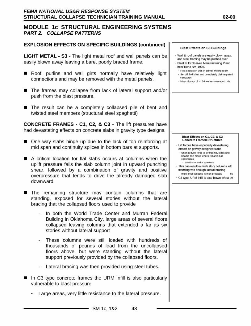
FEMA NATIONAL US&R RESPONSE SYSTEMSTRUCTURAL COLLAPSE TECHNICIAN TRAINING MANUAL 02-00
MODULE 1c STRUCTURAL ENGINEERING SYSTEMSPART 2. COLLAPSE PATTERNS
SM 1c, 1&2 48
EXPLOSION EFFECTS ON SPECIFIC BUILDINGS (continued)
LIGHT METAL - S3 - The light metal roof and wall panels can beeasily blown away leaving a bare, poorly braced frame.
n Roof, purlins and wall girts normally have relatively lightconnections and may be removed with the metal panels.
n The frames may collapse from lack of lateral support and/orpush from the blast pressure.
n The result can be a completely collapsed pile of bent andtwisted steel members (structural steel spaghetti)
CONCRETE FRAMES - C1, C2, & C3 - The lift pressures havehad devastating effects on concrete slabs in gravity type designs.
n One way slabs hinge up due to the lack of top reinforcing atmid span and continuity splices in bottom bars at supports.
n A critical location for flat slabs occurs at columns when theuplift pressure fails the slab column joint in upward punchingshear, followed by a combination of gravity and positiveoverpressure that tends to drive the already damaged slabdownward.
n The remaining structure may contain columns that arestanding, exposed for several stories without the lateralbracing that the collapsed floors used to provide
- In both the World Trade Center and Murrah FederalBuilding in Oklahoma City, large areas of several floorscollapsed leaving columns that extended a far as sixstories without lateral support
- These columns were still loaded with hundreds ofthousands of pounds of load from the uncollapsedfloors above, but were standing without the lateralsupport previously provided by the collapsed floors.
- Lateral bracing was then provided using steel tubes.
n In C3 type concrete frames the URM infill is also particularlyvulnerable to blast pressure
• Large areas, very little resistance to the lateral pressure.
Blast Effects on S3 Buildings Blast Effects on S3 Buildings
•• Wall & roof panels are easily blown away.Wall & roof panels are easily blown away.and steel framing may be pushed overand steel framing may be pushed over
•• Blast at Explosives Manufacturing PlantBlast at Explosives Manufacturing Plantnear Reno NV ,1998.near Reno NV ,1998.
–– First explosion was in primer mixing roomFirst explosion was in primer mixing room
–– Set off 2nd blast and completely disintegratedSet off 2nd blast and completely disintegratedstructures.structures.
–– Miraculously 12 of 16 workers escaped 4sMiraculously 12 of 16 workers escaped 4s
Blast Effects on C1, C2, & C3Blast Effects on C1, C2, & C3Concrete Framed StructuresConcrete Framed Structures
•• Lift forces have especially devastatingLift forces have especially devastatingeffects on gravity designed slabs effects on gravity designed slabs –– when gravity force is overcome, slabs andwhen gravity force is overcome, slabs and
beams can hinge where rebar is notbeams can hinge where rebar is notcontinuouscontinuous
•• at mid-span and at span ends at mid-span and at span ends
•• This can result in multi story columns leftThis can result in multi story columns leftstanding w/o enough lateral bracingstanding w/o enough lateral bracing–– multi level collapse is then probable 6smulti level collapse is then probable 6s
•• C3 type, URM infill is also blown in/out C3 type, URM infill is also blown in/out 2s2s

FEMA NATIONAL US&R RESPONSE SYSTEMSTRUCTURAL COLLAPSE TECHNICIAN TRAINING MANUAL 02-00
MODULE 1c STRUCTURAL ENGINEERING SYSTEMSPART 2. COLLAPSE PATTERNS
SM 1c, 1&2 49
EXPLOSION EFFECTS ON SPECIFIC BUILDINGS (continued)
PRECAST CONCRETE - PC2 In precast Frame typesstructures the lightly (gravity) connected floor slabs and wallplanes can be blown away, leaving unbraced beams andcolumns.
n If beam/column connections are minimal, entire sections ofthe structure could collapse.
• Progressive collapse has occurred when only one columnwas dislodged by a relatively small gas explosion in amulti-story-precast structure.
n In Box type PC2 (such as the barracks in Saudi Arabia) thewall and floor slabs nearest the blast may be dislodged, andbroken loose at their joints.
• The multi cellular character of these structures made fromclosely spaced bearing walls, however will tend to limit thecollapse damage to those areas where the bearingcapacity of wall panels is lost.
POST TENSIONED CONCRETE - If the unbonded cables aredamaged, becoming un-tensioned in only one small area of afloor slab, the entire length of the these cables can be effected,which can lead to the collapse of the full length of the floor.
n This type of slab is also very susceptible to upward pressuressince the cables are normally draped to lift the gravity weightof the structure
n The floor slabs or beams may also have some rebar, butthese bars are placed at the bottoms of slabs near mid-spanand at the top near supports (as in a normal gravity design)and will not be effect in resisting the upward pressures fromblasts.
n This is a Very Vulnerable and Dangerous Post BlastStructure.
Blast Effects on PC2 BuildingsBlast Effects on PC2 Buildings
•• PC2 - Frame type structuresPC2 - Frame type structures–– pressures can dislodge walls, slabspressures can dislodge walls, slabs
•• beams & columns then effected by lack of bracing.beams & columns then effected by lack of bracing.
–– break/damage many connectionsbreak/damage many connections
–– progressive collapse possible.progressive collapse possible.•• Due to missing supports and Due to missing supports and disdis-continuous members.-continuous members.
•• PC2 - Box type structuresPC2 - Box type structures–– pressures can dislodge walls & slabspressures can dislodge walls & slabs
•• break/damage many connectionsbreak/damage many connections
–– better response in multi wall buildings 1sbetter response in multi wall buildings 1s
Blast Effects on BuildingsBlast Effects on Buildings
•• Postensioned ConcretePostensioned Concrete- very vulnerable- very vulnerableto uplift pressures. progressive failureto uplift pressures. progressive failurewithin entire slab due to loss of tension inwithin entire slab due to loss of tension inunbonded cableunbonded cable
•• TU, RM, & URM - TU, RM, & URM - large wall & rooflarge wall & roofsurfaces effected. Lifted roof and blownsurfaces effected. Lifted roof and blownout ,farside walls 3sout ,farside walls 3s
Blast compared to very short term -Blast compared to very short term -high velocity wind w/special effectshigh velocity wind w/special effects

FEMA NATIONAL US&R RESPONSE SYSTEMSTRUCTURAL COLLAPSE TECHNICIAN TRAINING MANUAL 02-00
MODULE 1c STRUCTURAL ENGINEERING SYSTEMSPART 2. COLLAPSE PATTERNS
SM 1c, 1&2 50
EXPLOSION EFFECTS ON BUILDINGS (continued)
HEAVY WALL BUILDING - TU, RM, URM - Blast pressures willtend to engage the wall and roof surfaces, severing connectionsand blowing large sections away.
n For interior blasts, walls will blow out, and roof sections will belifted. Adjacent parts of the structure can also collapse due toloss of vertical and/or lateral support.
n For blasts initiated outside the building, the near walls may beshattered or blown in. This can be followed by having roofsections lifted, then dropped as well as having sections of thefar side blown out.
In summary the effects of explosions can be compared to avery short term, very high velocity wind. There may bespecial effects at corners and other discontinuities andshading of one part of a structure by another or one buildingby another.
REVIEW OF TOPICS
In this section we have discussed:n The types of forces that load structuresn The method that is used to classify structuresn The types of problems that various building types have
experienced in the past.n The various Collapse Patterns that have occurred that will
give us some insight as to how structures will behave in futuredisasters.
In Structural Engineering Systems – Parts 3 & 4 we will focusmore specifically on the US&R issues of how to deal withdamaged and collapsed structures.
Blast Effects on BuildingsBlast Effects on Buildings
•• PostenPosten - very vulnerable to uplift- very vulnerable to upliftpressures. progressive failure withinpressures. progressive failure withinentire slab due to loss of tension inentire slab due to loss of tension inunbonded cableunbonded cable
•• TU, RM, & URM - TU, RM, & URM - large wall & rooflarge wall & roofsurfaces effected. Lifted roof and blownsurfaces effected. Lifted roof and blownout ,farside walls 3sout ,farside walls 3s
Blast compared to very short term -Blast compared to very short term -high velocity wind w/special effectshigh velocity wind w/special effects
Review of TopicsReview of Topics
• Basic Structural Loading• ATC -21 building classification• Problematical building types
• Basic collapse patterns• Earthquake collapse patterns• Windstorm / flood collapse patterns• Blast effects on buildings