module 1c structural engineering systems · pdf filemodule 1c structural engineering systems...
TRANSCRIPT

FEMA NATIONAL US&R RESPONSE SYSTEMSTRUCTURAL COLLAPSE TECHNICIAN 02-00
MODULE 1C STRUCTURAL ENGINEERING SYSTEMSPART 3 - HAZARD IDENTIFICATION & BUILDING MONITORING
SM 1c, 3&4 1
OBJECTIVES
The objectives of this unit are to familiarize the student with themost common signs of distress exhibited by damaged structures.We have previously discussed Material Behavior and CollapsePatterns, and will now apply this knowledge to the Disaster Site.
n We will first discuss how Concrete and Masonry crack, and howthese cracks can be “READ” to predict future performance ofthese structures.
TERMINAL OBJECTIVESTERMINAL OBJECTIVES
•• The Student shall understand the mostThe Student shall understand the mostcommon signs of distress exhibited bycommon signs of distress exhibited bydamaged structures.damaged structures.
•• The Student shall understand to the mostThe Student shall understand to the mostcommon Hazards found in damagedcommon Hazards found in damagedstructures, and methods that have been usedstructures, and methods that have been usedto used to Mitigate themto used to Mitigate them
n We will then identify the most common Hazardous Conditionsthat will occur in the four types of buildings that we havepreviously identified.
n Finally we will discuss the various tools and methods that arecurrently available to Monitor Buildings
ENABLING OBJECTIVESENABLING OBJECTIVES
•• Understand the importance of the variousUnderstand the importance of the varioustypes of Cracks in Concrete and Masonrytypes of Cracks in Concrete and MasonryStructures.Structures.
•• Understand the common HazardousUnderstand the common HazardousConditions that occur in Light Frame, HeavyConditions that occur in Light Frame, HeavyWall, Heavy Floor and Wall, Heavy Floor and PrecastPrecast Buildings Buildings
•• Discuss the common methods andDiscuss the common methods andequipment used to Mitigate Structureequipment used to Mitigate StructureHazardsHazards
CRACKS IN REINFORCED CONCRETE & MASONRY
A favorite statement in building design and construction is; "If itsnot cracked, its not concrete," since cracks must form in concretefor the reinforcing steel to be stressed in tension. Most normal con-crete develops cracks that are narrow (hairline) as a result ofshrinkage, temperature change, and predictable structuralbehavior.
We need to apply ourWe need to apply our
knowledge regardingknowledge regarding
Material Behavior & CollapseMaterial Behavior & Collapse
Patterns to Disaster SitePatterns to Disaster Site
SHRINKAGE CRACKS
n Usually occur in slabs, beams, walls, and even in columnswithin 60 days of the pour, after the concrete is allowed to dryout.
n Diagonal cracks will originate from most re-entrant corners inslabs and walls i.e. window, door, and floor openings.
n Straight cracks (more or less) occur often at five to twenty feeton center in long wall and/or floor surfaces, depending on theamount of reinforcing steel, numbers of pour joints, and curingconditions.
n The reinforcing steel within the structure is intended to hold thestructure together as it shrinks, and keep these cracks small.
Cracks in Reinforced Concrete &Cracks in Reinforced Concrete &Reinforced MasonryReinforced Masonry
• shrinkage cracks• temperature cracks• tension cracks
• diagonal tension cracks in beams• diagonal tension cracks in walls
If it’s not Cracked it’s not ConcreteIf it’s not Cracked it’s not Concrete

FEMA NATIONAL US&R RESPONSE SYSTEMSTRUCTURAL COLLAPSE TECHNICIAN 02-00
MODULE 1C STRUCTURAL ENGINEERING SYSTEMSPART 3 - HAZARD IDENTIFICATION & BUILDING MONITORING
SM 1c, 3&4 2
TEMPERATURE CRACKS
n Occur in roughly the same pattern as shrinkage cracks, and aredifficult to differentiate from them.
n When the temperature of a concrete structure is decreased, itmust shorten (shrink) and, therefore, it cracks, and thereinforcing steel attempts to hold it together.
n Reinforced concrete structures will, obviously, have moreobservable temperature/ shrinkage cracking when subjected tothe winter cold.
TENSION CRACKS
n These most often occur in concrete slabs and beams whenbending caused, tension forces stretch the reinforcing steel
n Cracks must form in the concrete in order to transfer the force tothe steel, but the cracks normally are quite numerous, small andundetectable (except to the trained eye).
n They form, perpendicular to the long axis of the member, andas long as they remain hairlike, the structure is behavingnormally.
DIAGONAL TENSION CRACKS
n Occur in high shear stress zones of beams and girders in atypical pattern (HAZ-DTEN) under normal vertical loadconditions.
n In shearwalls, large diagonal tension cracks will form when thewalls are heavily loaded by severe earthquake shaking(HAZ-DTEN).
n Earthquakes will normally cause a diagonal crack in eachdirection (Cross Cracking) in the highly stressed areas ofshearwalls (i.e., between window openings, over stacked dooropenings) since the shear force reverses causing diagonaltension cracking in each direction.
Shrinkage & TemperatureShrinkage & TemperatureCracksCracks
• Occur in slabs, walls, beams, & columns.
• Diagonal cracks originate at re-entrantcorners in slabs & walls (openings)
• Transverse (more or less straight) cracksoccur at 5 to 20 ft apart in long slabs &walls
• Nominal rebar normally keep cracks small
FEMA NATIONAL US&R RESPONSE SYSTEMSTRUCTURAL COLLAPSE TECHNICIAN 02-00
MODULE 1C STRUCTURAL ENGINEERING SYSTEMSPART 3 - HAZARD IDENTIFICATION & BUILDING MONITORING
SM 1c, 3&4 3
DIAGONAL TENSION CRACKS (continued)

FEMA NATIONAL US&R RESPONSE SYSTEMSTRUCTURAL COLLAPSE TECHNICIAN 02-00
MODULE 1C STRUCTURAL ENGINEERING SYSTEMSPART 3 - HAZARD IDENTIFICATION & BUILDING MONITORING
SM 1c, 3&4 4
CRACKS IN REINFORCED CONCRETE WALLS
n The stability of concrete box-buildings will probably depend onthe post-cracked strength of the shear walls. Even withunsightly diagonal cracking, a shearwall may still have signifi-cant strength (HAZ-CK).
n The clamping action of the gravity loads, as well as the verticalrebar will tend to hold the irregular surface of the crackstogether, preventing the opposing surface from sliding. Inaddition the rebar that cross the crack can also act as dowels.
n Both these resistive actions are lessened when there is enoughshaking, or continued reshaking due to aftershocks that thecrack widens, concrete chunks fall out, and the rebar can beseen in an offset curved condition. In this later degradedcondition a shearwall has become unreliable and must beevaluated accordingly.
CRACKS IN URM WALLS & UR CONCRETE WALLS
n Shrinkage, temperature, and diagonal tension/shearwall cracksalso occur in URM and UR concrete walls. In these walls,however, cracking indicates a significantly degraded structure.
n Diagonal tension cracks form in these walls between openings,as they do in reinforced concrete walls due to earthquakeshaking. In addition cracks are often created at wall corners,with the bottom of the crack at the corner and the top extendingup to the roof. This is caused by the action of the disconnectedroof diaphragm pushing against the corner, attempting to push itout. URM diagonal cracks tend to follow a stair step pattern(HAZ-CK). That is, the crack follows the weaker mortar, ratherthan going through the bricks. This results in cracked surfacesthat are smoother than those in reinforced concrete.
n Masonry walls with significant diagonal tension cracks must beconsidered to be capable of a sudden, brittle failure. There issome clamping force on the horizontal steps of the cracks dueto the gravity force, but no vertical bars to add clamping ordowel action. The greater smoothness of the joints alsoreduces the friction that could be developed by the clamping ofthe vertical force.
n Unreinforced Concrete Walls also perform poorly duringquakes. They tend to break apart in pieces, defined bywhatever crack pattern existed prior and/or by the original pourjoints.
FEMA NATIONAL US&R RESPONSE SYSTEMSTRUCTURAL COLLAPSE TECHNICIAN 02-00
MODULE 1C STRUCTURAL ENGINEERING SYSTEMSPART 3 - HAZARD IDENTIFICATION & BUILDING MONITORING
SM 1c, 3&4 5
CRACKS IN REINFORCED CONCRETE & URM SHEARWALLS

FEMA NATIONAL US&R RESPONSE SYSTEMSTRUCTURAL COLLAPSE TECHNICIAN 02-00
MODULE 1C STRUCTURAL ENGINEERING SYSTEMSPART 3 - HAZARD IDENTIFICATION & BUILDING MONITORING
SM 1c, 3&4 6
HAZARD IDENTIFICATION
In damaged, partly collapsed and collapsed structures we canidentify three types of hazards:
n Falling where part of the structure or its contents are in dangerof falling.
n Collapse where the volume of enclosed space made by thestructure will be reduced, as stability is lost.
n Other -toxic gas, carbon monoxide, asbestos, other hazardousmaterials (discussed in Haz Mat 1st Responder Course).
Hazards in Damaged StructureHazards in Damaged Structure
• Falling hazards
• Collapse hazards• Other hazards
n Falling and collapse hazards will be discussed here. Thedegree of hazard in both cases is strongly related to mass andhow additional failure may occur. Brittle, sudden failure potentialmust be recognized as contrasted to structures where materialductility and redundant configuration could provide somewarning of an additional collapse.
n The problem of identifying, let alone properly evaluating thesehazards, is staggering. A well-trained engineer may, at best, beable to rate the risk of various hazards on some arbitrary scalelike bad, very bad, and deadly. We must consider that:• Judgments can not be precise.• We must try to identify brittle vs ductile behavior.• Partial collapse is very difficult to assess.• The cause of the condition is very important input (i.e.,
earthquake with expected after-shock, windstorm, etc.).
Identification ProblemsIdentification Problems
•• Judgments cannot be preciseJudgments cannot be precise
•• Partially collapsed structures difficultPartially collapsed structures difficult
•• Collapsed structure has come to rest, but it isCollapsed structure has come to rest, but it isnow weaker and more disorganized thannow weaker and more disorganized thanoriginal structure.original structure.
•• Earthquake may have caused partialEarthquake may have caused partialcollapse, but building remainder may becollapse, but building remainder may beweakened & ready to collapse in Aftershock.weakened & ready to collapse in Aftershock.
•• Structures Collapse in AftershocksStructures Collapse in Aftershocks
n In evaluating, if a specific structure is at rest, one could state, onthe positive side that the structure that was moving had enoughresistance to stop moving and achieve, at least temporarystability. However, the damaged structure is difficult to assess,weaker, and more disorganized than the original.
• Try to identify the load path, and visualize what couldhappen during an aftershock or wind gust.
• Small, nonstructural elements and debris (loose materials)may be greater hazards than overall structural stabilityespecially in wind gusts and small aftershocks.
FEMA NATIONAL US&R RESPONSE SYSTEMSTRUCTURAL COLLAPSE TECHNICIAN 02-00
MODULE 1C STRUCTURAL ENGINEERING SYSTEMSPART 3 - HAZARD IDENTIFICATION & BUILDING MONITORING
SM 1c, 3&4 7
LIGHT FRAME BUILDING HAZARDS
Principal weakness is in lateral strength of walls and connections.
n Check Points: (HAZ-LF)• Badly cracked or leaning walls.• Offset residence from foundation• Leaning 1st story in multi-story buildings.• Cracked, leaning masonry chimney or veneer.• Separated porches, split level floors/roof.
FEMA NATIONAL US&R RESPONSE SYSTEMSTRUCTURAL COLLAPSE TECHNICIAN 02-00
MODULE 1C STRUCTURAL ENGINEERING SYSTEMSPART 3 - HAZARD IDENTIFICATION & BUILDING MONITORING
SM 1c, 3&4 8
LIGHT FRAME BUILDING HAZARDS (continued)
n In less than three story structures additional collapse is unlikely due to the lightweight of this typeof construction. Collapse of this type is often slow and noisy. Falling masonry chimneys andmasonry veneers are the most brittle types of behavior for these structures
FEMA NATIONAL US&R RESPONSE SYSTEMSTRUCTURAL COLLAPSE TECHNICIAN 02-00
MODULE 1C STRUCTURAL ENGINEERING SYSTEMSPART 3 - HAZARD IDENTIFICATION & BUILDING MONITORING
SM 1c, 3&4 9
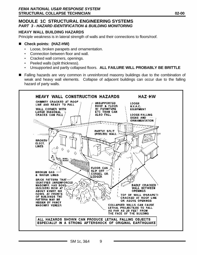
HEAVY WALL BUILDING HAZARDSPrinciple weakness is in lateral strength of walls and their connections to floors/roof.
n Check points: (HAZ-HW)• Loose, broken parapets and ornamentation.• Connection between floor and wall.• Cracked wall corners, openings.• Peeled walls (split thickness).• Unsupported and partly collapsed floors. ALL FAILURE WILL PROBABLY BE BRITTLE
n Falling hazards are very common in unreinforced masonry buildings due to the combination ofweak and heavy wall elements. Collapse of adjacent buildings can occur due to the fallinghazard of party walls.
FEMA NATIONAL US&R RESPONSE SYSTEMSTRUCTURAL COLLAPSE TECHNICIAN 02-00
MODULE 1C STRUCTURAL ENGINEERING SYSTEMSPART 3 - HAZARD IDENTIFICATION & BUILDING MONITORING
SM 1c, 3&4 10
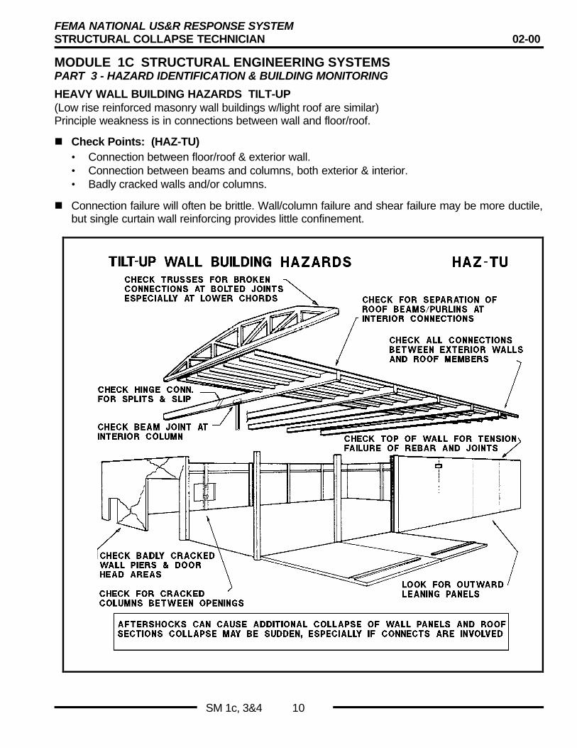
HEAVY WALL BUILDING HAZARDS TILT-UP(Low rise reinforced masonry wall buildings w/light roof are similar)Principle weakness is in connections between wall and floor/roof.
n Check Points: (HAZ-TU)• Connection between floor/roof & exterior wall.• Connection between beams and columns, both exterior & interior.• Badly cracked walls and/or columns.
n Connection failure will often be brittle. Wall/column failure and shear failure may be more ductile,but single curtain wall reinforcing provides little confinement.

FEMA NATIONAL US&R RESPONSE SYSTEMSTRUCTURAL COLLAPSE TECHNICIAN 02-00
MODULE 1C STRUCTURAL ENGINEERING SYSTEMSPART 3 - HAZARD IDENTIFICATION & BUILDING MONITORING
SM 1c, 3&4 11
HEAVY FLOOR BUILDING HAZARDS CONCRETE FRAMESPrinciple weakness is lack of adequate column reinforcing that can properly confine the concreteand inadequate connection between slabs and columns.
n Check Points: (HAZ-HF)• Confinement of concrete in columns (empty basket).• Cracking of columns at each floor line (above and below floor).• Diagonal shear cracking in major beams adjacent to supporting columns and walls.• Cracking in flat slabs adjacent to columns.• Attachment of heavy non-structural, unreinforced masonry walls (infill walls).• Cracks in concrete shear walls and/or stairs.
n Ductile behavior may still be possible if concrete is confined by reinforcing and the reinforcing isstill within lower yielding range.
FEMA NATIONAL US&R RESPONSE SYSTEMSTRUCTURAL COLLAPSE TECHNICIAN 02-00
MODULE 1C STRUCTURAL ENGINEERING SYSTEMSPART 3 - HAZARD IDENTIFICATION & BUILDING MONITORING
SM 1c, 3&4 12
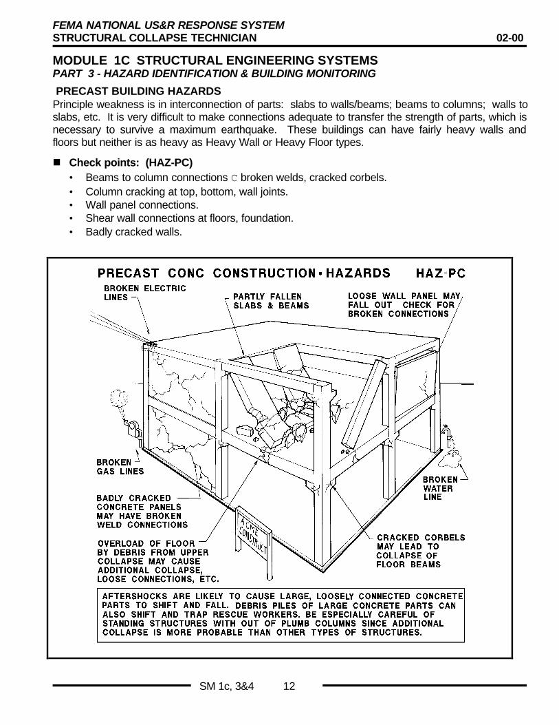
PRECAST BUILDING HAZARDSPrinciple weakness is in interconnection of parts: slabs to walls/beams; beams to columns; walls toslabs, etc. It is very difficult to make connections adequate to transfer the strength of parts, which isnecessary to survive a maximum earthquake. These buildings can have fairly heavy walls andfloors but neither is as heavy as Heavy Wall or Heavy Floor types.
n Check points: (HAZ-PC)• Beams to column connections C broken welds, cracked corbels.• Column cracking at top, bottom, wall joints.• Wall panel connections.• Shear wall connections at floors, foundation.• Badly cracked walls.
FEMA NATIONAL US&R RESPONSE SYSTEMSTRUCTURAL COLLAPSE TECHNICIAN 02-00
MODULE 1C STRUCTURAL ENGINEERING SYSTEMSPART 3 - HAZARD IDENTIFICATION & BUILDING MONITORING
SM 1c, 3&4 13
PRECAST BUILDING HAZARDS (continued)
n These structures are often made from lightweight concrete. Itshould be noted that lightweight concrete splits more easily thannormal weight concrete.
n Most failures that occur due to broken connections will be brittle.
n Since individual building parts may be quite strong, crackedconcrete failures may be ductile if adequate bonded reinforcingis present.
n Depending on extent of collapse many falling hazards may bepresent.
Other Hazard I. D.Other Hazard I. D.
• PostTensioned Concrete Slabs presentunique Hazards 2s– After cables become loose, slabs act more
like unreinforced concrete.
– Cables normally extend full length/width ofslab . (? loose full length of cable)
– If cables are still stressed, must cut withgreat care.
• Geologic Hazards - effect structures 2s
SUMMARY OF HAZARD IDENTIFICATION
The problems of identifying hazards after structural collapse areextremely difficult.
n Buildings are often complicated and there are many differenttypes and configurations.
n What remains after the triggering event may have come to rest,but the danger of further collapse and/or falling objects is oftenpresent?
n These hazards should be identified by a qualified engineer whounderstands the basic behavior of structures.
n Brittle conditions pose the greatest threat due to the probabilityof sudden failure.
n As many hazards as possible should be identified, and probablerisk factors assigned to them.
n Measures to avoid or mitigate the danger can then be factoredinto the overall search and rescue effort.
Hazard Identification SummaryHazard Identification Summary
• Structure has come to rest but manyhazards may remain
• Aftershocks & strong winds may causefalling objects & additional collapse
• Hazards need to be identified & relativerisk factors assigned
• Mitigation measures then need to bedesigned in concert with the SAR effort
FEMA NATIONAL US&R RESPONSE SYSTEMSTRUCTURAL COLLAPSE TECHNICIAN 02-00
MODULE 1C STRUCTURAL ENGINEERING SYSTEMSPART 3 - HAZARD IDENTIFICATION & BUILDING MONITORING
SM 1c, 3&4 14
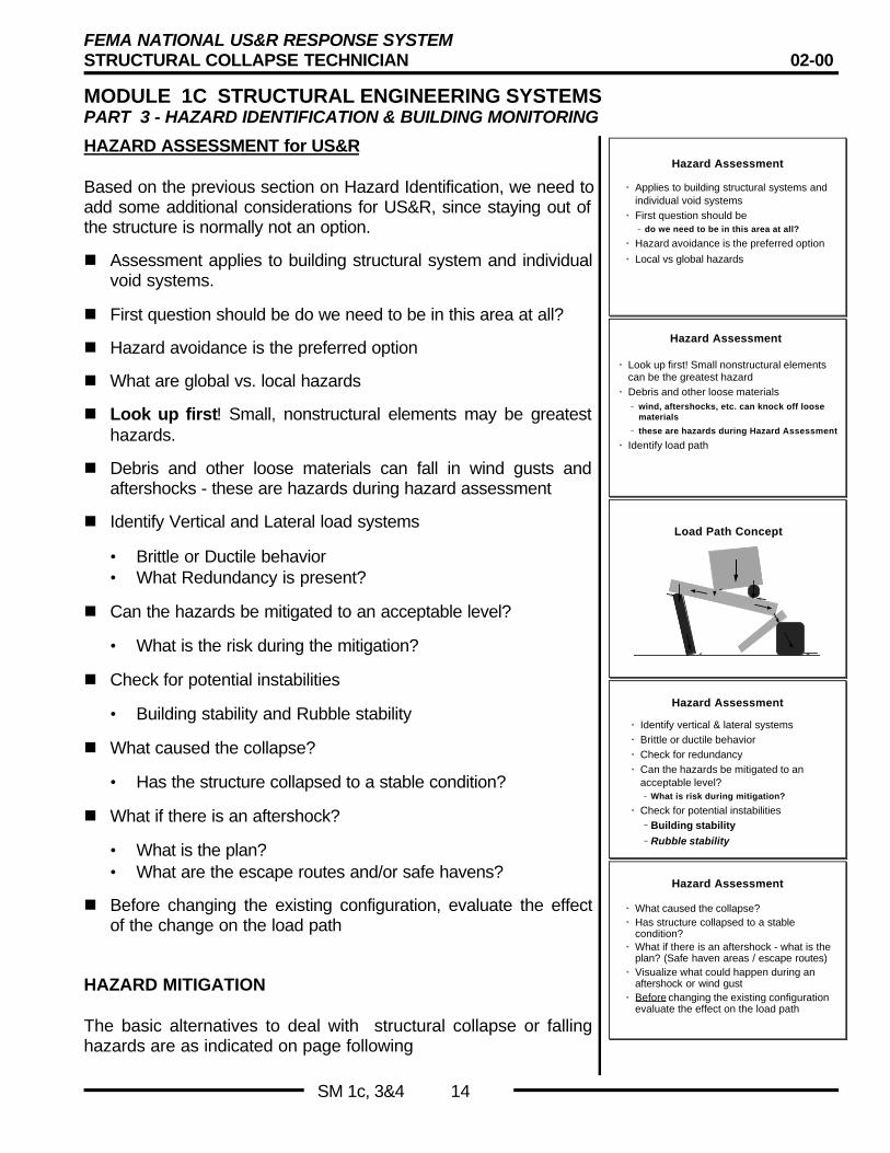
HAZARD ASSESSMENT for US&R
Based on the previous section on Hazard Identification, we need toadd some additional considerations for US&R, since staying out ofthe structure is normally not an option.
n Assessment applies to building structural system and individualvoid systems.
n First question should be do we need to be in this area at all?
n Hazard avoidance is the preferred option
n What are global vs. local hazards
n Look up first! Small, nonstructural elements may be greatesthazards.
n Debris and other loose materials can fall in wind gusts andaftershocks - these are hazards during hazard assessment
n Identify Vertical and Lateral load systems
• Brittle or Ductile behavior• What Redundancy is present?
n Can the hazards be mitigated to an acceptable level?
• What is the risk during the mitigation?
n Check for potential instabilities
• Building stability and Rubble stability
n What caused the collapse?
• Has the structure collapsed to a stable condition?
n What if there is an aftershock?
• What is the plan?• What are the escape routes and/or safe havens?
n Before changing the existing configuration, evaluate the effectof the change on the load path
HAZARD MITIGATION
The basic alternatives to deal with structural collapse or fallinghazards are as indicated on page following
Hazard Assessment
• Applies to building structural systems andindividual void systems
• First question should be– do we need to be in this area at all?
• Hazard avoidance is the preferred option
• Local vs global hazards
Hazard Assessment
• Look up first! Small nonstructural elementscan be the greatest hazard
• Debris and other loose materials– wind, aftershocks, etc. can knock off loose
materials
– these are hazards during Hazard Assessment
• Identify load path
Load Path Concept
Hazard Assessment
• Identify vertical & lateral systems• Brittle or ductile behavior• Check for redundancy• Can the hazards be mitigated to an
acceptable level?– What is risk during mitigation?
• Check for potential instabilities– Building stability– Rubble stability
Hazard Assessment
• What caused the collapse?• Has structure collapsed to a stable
condition?• What if there is an aftershock - what is the
plan? (Safe haven areas / escape routes)• Visualize what could happen during an
aftershock or wind gust• Before changing the existing configuration
evaluate the effect on the load path

FEMA NATIONAL US&R RESPONSE SYSTEMSTRUCTURAL COLLAPSE TECHNICIAN 02-00
MODULE 1C STRUCTURAL ENGINEERING SYSTEMSPART 3 - HAZARD IDENTIFICATION & BUILDING MONITORING
SM 1c, 3&4 15
HAZARD MITIGATION (continued)
n AVOID Plan direction of SAR activities away from hazard andits effects. Access of badly collapsed structure should startfrom the top, rather than from the edge (between layers), orthan by tunneling. The use of mining techniques of tunnelingand shoring with individual vertical posts has lead to aftershockcaused shore failures. Consider alternatives, consult withothers, be as resourceful as possible.
n EXPOSURE REDUCTION One of the most efficient methodsof hazard reduction is to limit the time of exposure, and to limitthe number rescuers that are being exposed to a potentiallydangerous situation. Because of the natural tendency ofrescuers to be helpful and Part of the Action, one will often findmore than the minimum required number in a confined spaceespecially when a live rescue in nearing completion. Risk is afunction of both severity and exposure.
n REMOVE May be more efficient than shoring. Parts of URMwalls may be removed by hand, using aerial ladders for upperportions, or in larger pieces using crane and clamshell. Precastconcrete sections are more easily removed by small cranes orother concrete removal machines, due to their moderate sizeand lack of interconnections compared to cast in placeconcrete. If at all possible - Lift Off, Push Over, or Pull Down(safely of course) as a first choice
n SHORE Provide both vertical and lateral support, build safehaven areas. This will be discussed in detail in its own section,with special emphasis on slow/forgiving failure modes. Lateralbracing of damaged columns, beams, and entire leaningbuildings may be required. Tension tieback bracing can also beeffective for holding walls, and cranes have been used totemporally suspend parts of damaged buildings.
n MONITOR as discussed previously, methods including the useof crack measuring devices, Theodolites and other tiltmeasuring devices (Change in Tilt) are used to monitordamaged structures. To be effective these devices must becontinually read and accompanied by an effective alarm systemthat activates an efficient evacuation plan.
n RECOGNIZE and refer hazardous materials to HazmatSpecialist. Eliminate/Shut off all possible fire hazards.
Simple Hazard MitigationSimple Hazard Mitigation
•• AvoidAvoid–– Need effective barrier systemNeed effective barrier system
•• RemovalRemoval–– Lift off, push over, pull downLift off, push over, pull down
•• Exposure reductionExposure reduction–– How long do we need to be in the area?How long do we need to be in the area?–– Risk is a function of severity and exposureRisk is a function of severity and exposure–– limit time exposed to hazardlimit time exposed to hazard–– limit number of personnel exposedlimit number of personnel exposed
Similar to Time, Distance, & ShieldingSimilar to Time, Distance, & ShieldingRule used in HazmatRule used in Hazmat
Other Hazard Mitigation
• Vertical & Lateral Shoring– system with slow failure mode
• Lateral Bracing• Lateral Tieback
– when shoring isn’t practical• Vertical Tieback
– use crane to hang structure
• Monitor - with alarm & escape system• Recognize & Refer Hazard (hazmat)
FEMA NATIONAL US&R RESPONSE SYSTEMSTRUCTURAL COLLAPSE TECHNICIAN 02-00
MODULE 1C STRUCTURAL ENGINEERING SYSTEMSPART 3 - HAZARD IDENTIFICATION & BUILDING MONITORING
SM 1c, 3&4 16
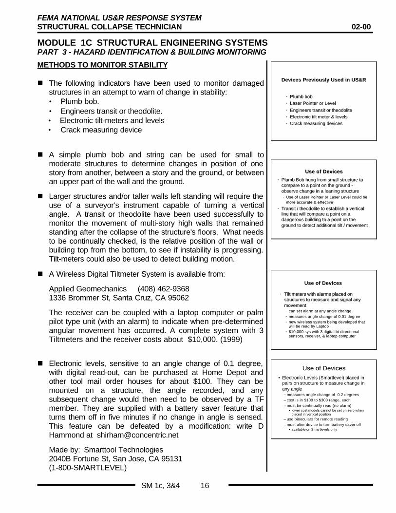
METHODS TO MONITOR STABILITY
n The following indicators have been used to monitor damagedstructures in an attempt to warn of change in stability:• Plumb bob.• Engineers transit or theodolite.• Electronic tilt-meters and levels• Crack measuring device
Devices Previously Used in US&RDevices Previously Used in US&R
•• Plumb bobPlumb bob
•• Laser Pointer or LevelLaser Pointer or Level
•• Engineers transit or theodoliteEngineers transit or theodolite•• Electronic tilt meter & levelsElectronic tilt meter & levels
•• Crack measuring devicesCrack measuring devices
n A simple plumb bob and string can be used for small tomoderate structures to determine changes in position of onestory from another, between a story and the ground, or betweenan upper part of the wall and the ground.
n Larger structures and/or taller walls left standing will require theuse of a surveyor’s instrument capable of turning a verticalangle. A transit or theodolite have been used successfully tomonitor the movement of multi-story high walls that remainedstanding after the collapse of the structure's floors. What needsto be continually checked, is the relative position of the wall orbuilding top from the bottom, to see if instability is progressing.Tilt-meters could also be used to detect building motion.
Use of DevicesUse of Devices
•• Plumb Bob hung from small structure toPlumb Bob hung from small structure tocompare to a point on the ground -compare to a point on the ground -observe change in a leaning structureobserve change in a leaning structure–– Use of Laser Pointer or Laser Level could beUse of Laser Pointer or Laser Level could be
more accurate & effectivemore accurate & effective
•• Transit / theodolite to establish a verticalTransit / theodolite to establish a verticalline that will compare a point on aline that will compare a point on adangerous building to a point on thedangerous building to a point on theground to detect additional tilt / movementground to detect additional tilt / movement
n A Wireless Digital Tiltmeter System is available from:
Applied Geomechanics (408) 462-93681336 Brommer St, Santa Cruz, CA 95062
The receiver can be coupled with a laptop computer or palmpilot type unit (with an alarm) to indicate when pre-determinedangular movement has occurred. A complete system with 3Tiltmeters and the receiver costs about $10,000. (1999)
Use of DevicesUse of Devices
•• Tilt meters with alarms placed onTilt meters with alarms placed onstructures to measure and signal anystructures to measure and signal anymovementmovement–– can set alarm at any angle changecan set alarm at any angle change–– measures angle change of 0.01 degreemeasures angle change of 0.01 degree–– new wireless system being developed thatnew wireless system being developed that
will be read by Laptopwill be read by Laptop–– $10,000 sys with 3 digital bi-directional$10,000 sys with 3 digital bi-directional
sensors, receiver, & laptop computersensors, receiver, & laptop computer
n Electronic levels, sensitive to an angle change of 0.1 degree,with digital read-out, can be purchased at Home Depot andother tool mail order houses for about $100. They can bemounted on a structure, the angle recorded, and anysubsequent change would then need to be observed by a TFmember. They are supplied with a battery saver feature thatturns them off in five minutes if no change in angle is sensed.This feature can be defeated by a modification: write DHammond at [email protected]
Made by: Smarttool Technologies2040B Fortune St, San Jose, CA 95131(1-800-SMARTLEVEL)
Use of DevicesUse of Devices• Electronic Levels (Smartlevel) placed in
pairs on structure to measure change inany angle– measures angle change of 0.2 degrees– cost is in $100 to $300 range, each– must be continually read (no alarm)
• lower cost models cannot be set on zero whenplaced in vertical position
– use binoculars for remote reading– must alter device to turn battery saver off
• available on Smartlevels only

FEMA NATIONAL US&R RESPONSE SYSTEMSTRUCTURAL COLLAPSE TECHNICIAN 02-00
MODULE 1C STRUCTURAL ENGINEERING SYSTEMSPART 3 - HAZARD IDENTIFICATION & BUILDING MONITORING
SM 1c, 3&4 17
CRACK MEASURING DEVICES
Cracks in concrete or masonry shearwalls or concrete momentframe beams can be monitored in several ways. Obviously, it isimportant to know if the cracks in a damaged building are of aconstant width or enlarging. Methods that have been usedinclude:
n Marking an "X" across the crack with the center on the crack.Significant lateral movement changes can be observed.
n Placing folded paper in cracks or use automobile thicknessgages (.004" to .025") to measure a specific location.
n Adhesive or other tape may be placed across the joint tomeasure change, but dusty conditions may prevent tape fromadhering. (Need to be prepared to clean surfaces if this is onlyoption that is available.)
n Two parallel sticks (rulers) can be taped across a crack with aperpendicular line being drawn across both of them (or existinglines on two rulers can be aligned). If the crack changes width,then the originally straight line will be offset.
n Plastic Strain gages (about $15 ea. in1999 ) may be placedacross cracks to also indicate change. (mount with paste typeepoxy)Made by: Avongard, (708) 244-41792836 Osage, Waukegan, IL, 60087
n It should be noted that if the structure has significant changes intemperature, the cracks will change width, due to thetemperature change. The larger the structure the larger thechange.
METHOD TO MONITOR DISASTER SITE
SEISMIC TRIGGER DEVICEThis can be installed at the site to sense the initial P waves ofstrong aftershocks. Since the P waves travel at 5 km/sec max. andthe damaging S waves follow at approx. 3 km/sec, a warning signalcould be triggered at a building site prior to the damaging effects ofthe S wave.
n The device comes in a portable carrying case and would needto be bolted to a solid slab/foundation, etc. somewhere near adamaged building.
Cracks can be Monitored byCracks can be Monitored by
• Drawing or sawcut ‘x’ centered oncrack
• Inexpensive ($15) plastic strain gagecan be placed at crack
• Spray paint cracked area
Method to Monitor Disaster SiteMethod to Monitor Disaster Site• Time delay for S waves to travel from
Fault to Site gives opportunity for warningof Aftershocks
• Seismic Trigger deployed at Disaster Site– warns when P wave arrives– destructive S wave arrives later
• Pager System– pagers at disaster site are signaled from
sensors at fault that measure Aftershocks
FEMA NATIONAL US&R RESPONSE SYSTEMSTRUCTURAL COLLAPSE TECHNICIAN 02-00
MODULE 1C STRUCTURAL ENGINEERING SYSTEMSPART 3 - HAZARD IDENTIFICATION & BUILDING MONITORING
SM 1c, 3&4 18
SEISMIC TRIGGER DEVICE continued
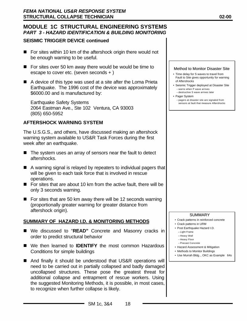
n For sites within 10 km of the aftershock origin there would notbe enough warning to be useful.
n For sites over 50 km away there would be would be time toescape to cover etc. (seven seconds + )
n A device of this type was used at a site after the Loma PrietaEarthquake. The 1996 cost of the device was approximately$6000.00 and is manufactured by:
Earthquake Safety Systems2064 Eastman Ave., Ste 102 Ventura, CA 93003(805) 650-5952
AFTERSHOCK WARNING SYSTEM
The U.S.G.S., and others, have discussed making an aftershockwarning system available to US&R Task Forces during the firstweek after an earthquake.
n The system uses an array of sensors near the fault to detectaftershocks.
n A warning signal is relayed by repeaters to individual pagers thatwill be given to each task force that is involved in rescueoperations.
n For sites that are about 10 km from the active fault, there will beonly 3 seconds warning.
n For sites that are 50 km away there will be 12 seconds warning(proportionally greater warning for greater distance fromaftershock origin).
SUMMARY OF HAZARD I.D. & MONITORING METHODS
n We discussed to “READ” Concrete and Masonry cracks inorder to predict structural behavior
n We then learned to IDENTIFY the most common HazardousConditions for simple buildings
n And finally it should be understood that US&R operations willneed to be carried out in partially collapsed and badly damageduncollapsed structures. These pose the greatest threat foradditional collapse and entrapment of rescue workers. Usingthe suggested Monitoring Methods, it is possible, in most cases,to recognize when further collapse is likely.
Method to Monitor Disaster SiteMethod to Monitor Disaster Site• Time delay for S waves to travel from
Fault to Site gives opportunity for warningof Aftershocks
• Seismic Trigger deployed at Disaster Site– warns when P wave arrives– destructive S wave arrives later
• Pager System– pagers at disaster site are signaled from
sensors at fault that measure Aftershocks
SUMMARYSUMMARY• Crack patterns in reinforced concrete• Crack patterns in URM• Post Earthquake Hazard I.D.
– Light Frame
– Heavy Wall
– Heavy Floor
– Precast Concrete
• Hazard Assessment & Mitigation• Methods to Monitor Buildings• Use Murrah Bldg.., OKC as Example 64s
FEMA NATIONAL US&R RESPONSE SYSTEMSTRUCTURAL COLLAPSE TECHNICIAN 02-00
MODULE 1C STRUCTURAL ENGINEERING SYSTEMSPART 4 - US&R STRATEGY & STRUCTURE SIZEUP
SM 1c, 3&4 19
Strategies will be presented from a Structures Hazards point of view. Other input such as medicalurgency, availability of special equipment and/or trained personnel, other hazardous conditions willalso need to be considered.
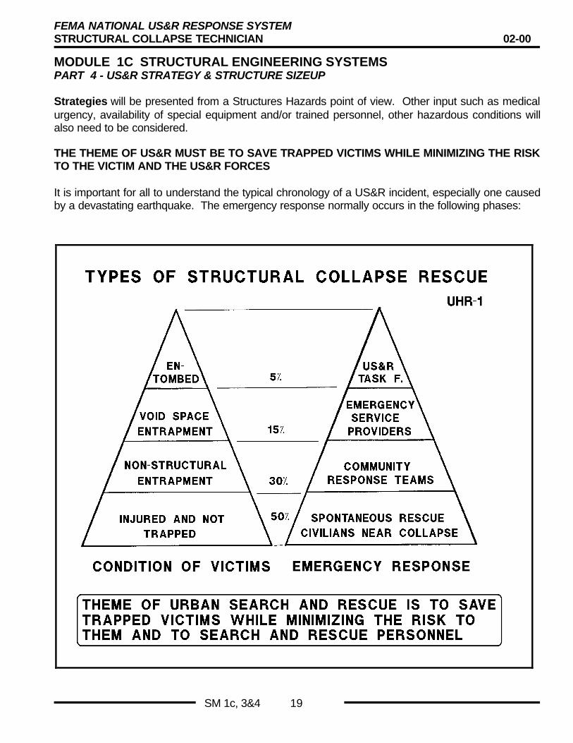
THE THEME OF US&R MUST BE TO SAVE TRAPPED VICTIMS WHILE MINIMIZING THE RISKTO THE VICTIM AND THE US&R FORCES
It is important for all to understand the typical chronology of a US&R incident, especially one causedby a devastating earthquake. The emergency response normally occurs in the following phases:

FEMA NATIONAL US&R RESPONSE SYSTEMSTRUCTURAL COLLAPSE TECHNICIAN 02-00
MODULE 1C STRUCTURAL ENGINEERING SYSTEMSPART 4 - US&R STRATEGY & STRUCTURE SIZEUP
SM 1c, 3&4 20
TERMINAL OBJECTIVESTERMINAL OBJECTIVES
•• The Student shall understand the PhasesThe Student shall understand the Phasesof a large disaster and how the FEMAof a large disaster and how the FEMAUS&R Task Force most commonly isUS&R Task Force most commonly isdeployed to perform it’s initial tasks.deployed to perform it’s initial tasks.
•• The Student shall understand to the mostThe Student shall understand to the mostappropriate strategies to be used to effectappropriate strategies to be used to effectrescues in various types of structures.rescues in various types of structures.
ENABLING OBJECTIVESENABLING OBJECTIVES
•• Understand what normally occurs during theUnderstand what normally occurs during theinitial phases of Task Force Deploymentinitial phases of Task Force Deployment–– Structure TriageStructure Triage
–– Building I.D. and Marking SystemsBuilding I.D. and Marking Systems
•• Understand the Basic Strategies that shouldUnderstand the Basic Strategies that shouldbe employed to produce the best results forbe employed to produce the best results formost structures.most structures.
The Objectives of this section are given in the adjacent slides
PHASES OF LARGE DISASTER (continued)
n Initial spontaneous response C unskilled, neighbors,community response teams, passers-by will heroically helpremove lightly trapped and/or injured victims. These rescuershave often acted far beyond their normal skill level and oftensave three-fourths or more of the total. Survival rates arerelatively high, since victims are normally not entrapped. Pro-fessional firefighter, law enforcement officers, and emergencymedical personnel may participate and better organize theresponse. This phase will often end during the first night.
n Planned Community Response by local trained communityresponse teams. Call-out and visual search would be used tolocate and rescue the non-structurally trapped. Some lifting ofobjects (furniture, bookcases, etc.) would be done as well asmitigation of hazards (extinguish small fires, turn off gas,observe/refer hazardous materials).
n Void Space Rescue by local emergency services rescueforces. Search elements would help prioritize site to make betterrisk vs. benefit judgments. Rescue would proceed using existingcavities, duct/plumbing shafts, basements, and/or small cutopenings in easily breachable floors and walls. Some shoringmight be done to provide safe haven areas and otherwiseprotect emergency responders and/or victims. This phase maystart the first day, but often, not until after some organizingefforts have taken place, requiring at least one hour.
n Technical, Urban Search & Rescue by trained US&R forces,aided by equipment. Site or sites would be re-evaluated, re-searched, and prioritized for the ten- daylong effort. Extensivecutting, shoring, etc. may be done to penetrate the structure.Cranes may be used to remove layers of structural debris orparts of the structure that are hazardous.
ENABLING OBJECTIVESENABLING OBJECTIVES
•• Discuss Strategies that should produceDiscuss Strategies that should producebest results for specific types of Buildings.best results for specific types of Buildings.
–– SearchSearch
–– Hazard ReductionHazard Reduction
–– Victim Access including the cutting ofVictim Access including the cutting ofconcreteconcrete
•• Learn from the presentation of examplesLearn from the presentation of examplesfrom previous incidents.from previous incidents.
Phases of Large DisasterEarthquake - Hurricane
5 to 10%
15%
30%
50% SpontaneousCivilians Nearby
CommunityResponse Teams
Lt. Rescue Teams
TFUS&R
LightlyTrapped
Non-StructureEntrapment
Injured and Not Trapped
Tra-pped
CONDITION of VICTIMS EMERGENCY RESPONSE

FEMA NATIONAL US&R RESPONSE SYSTEMSTRUCTURAL COLLAPSE TECHNICIAN 02-00
MODULE 1C STRUCTURAL ENGINEERING SYSTEMSPART 4 - US&R STRATEGY & STRUCTURE SIZEUP
SM 1c, 3&4 21
INITIAL INFORMATION GATHERING
Information gathering techniques will be crucial to the efficienttransition of the US&R forces into the incident. It is important forthese incoming forces to carefully verify information obtainedfrom the first responders and other individuals at the disaster site.By the time the information exchange takes place, the firstresponders will probably be subjected to the following:
n A many hour period of physically and emotionally draining work.Feelings that it's not possible that other victims have survivedwithin a badly collapsed structure.
n A need to experience closure; that the incident is over.
n Feelings by relatives/friends of the missing that they have surelysurvived and are entrapped.
n The information gathering must therefore, proceed as swiftlyand unemotionally as possible, while testing all currentassumptions. Information from others on structural safety issuesshould be recorded, but the Search Specialist should performhis own assessment, independently, as in any good check.
TYPICAL FIRST HOURS DEPLOYMENT
Initial Phases of T F Deployment
• Information Gathering• Building Identification System• Structure Triage• Search & Recon - Deployment Options
• Structure / Hazards Evaluation & Marking• Search Assessment Marking• Victim Marking
Information Gathering by TF
• Critical for transition from Initial Phase todeployment of US&R TF
• First responders may have experienced:– long period of emotional & physically draining
work
– need to feel that no-one else is trapped
– need to feel closure
– requests by relatives/friends to find their lovedones (they KNOW they are alive)
Information Gathering by TF
• Task Force must proceed swiftly and un-emotionally
• Must test ALL previous assumptions• Perform Independent Assessments
• In multi-TF deployments ALL on-comingStruc. & Hazmat Spec should performIndependent Structure/HazardAssessments
There are many possible Scenarios to which a US&R Task Forceor a number of Task Forces could respond. However, ourOperating System Description (OSD) envisions that, after initialsetup, a decision needs to be made as to the most appropriatedeployment of TF Structure Triage and Search & Reconcomponents. Some initial questions that need to be answered are:
n Is Structure Triage needed or have initial priorities beenestablished by others?
n How many building have been assigned to the TF, and doesSearch and Recon need to be carried out at one or morelocations?
n How remote are the buildings assigned to TF?
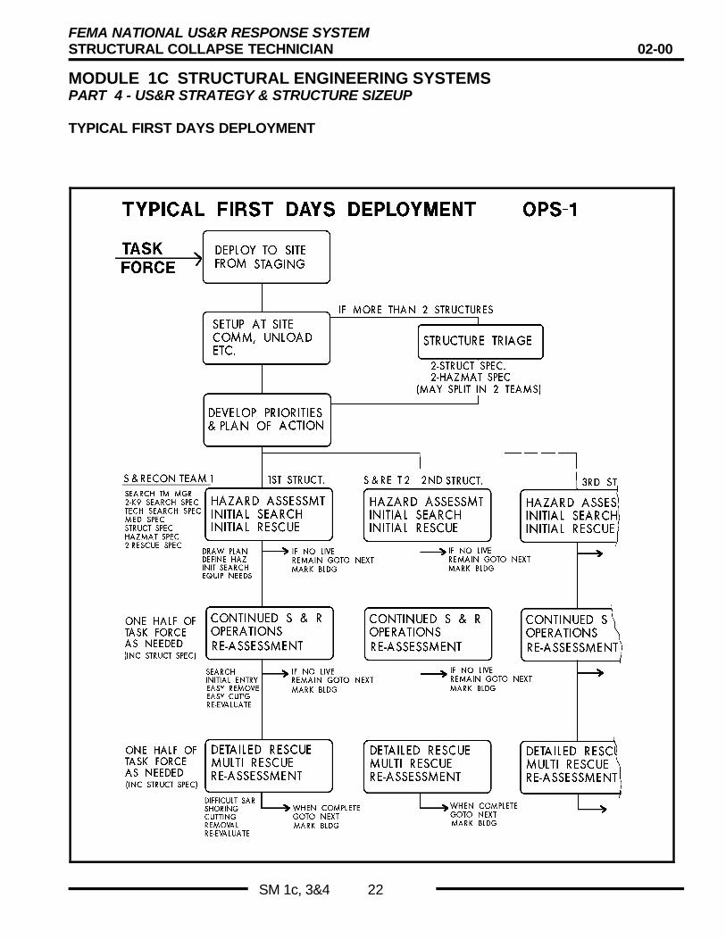
On the following page a flow chart is shown to illustrate a simplistic3 building scenario:
TYPICAL 1STHOURS
DEPLOYMENT
Deploy to sitefrom Staging
Base of OpsSet Up
StructureTriage
DevelopPriorities& Plan
Four or more Bldgs
2-Struct Spec2-Hazmat Spec(may split intotwo teams)
Search & Recon
FEMA NATIONAL US&R RESPONSE SYSTEMSTRUCTURAL COLLAPSE TECHNICIAN 02-00
MODULE 1C STRUCTURAL ENGINEERING SYSTEMSPART 4 - US&R STRATEGY & STRUCTURE SIZEUP
SM 1c, 3&4 22
TYPICAL FIRST DAYS DEPLOYMENT

FEMA NATIONAL US&R RESPONSE SYSTEMSTRUCTURAL COLLAPSE TECHNICIAN 02-00
MODULE 1C STRUCTURAL ENGINEERING SYSTEMSPART 4 - US&R STRATEGY & STRUCTURE SIZEUP
SM 1c, 3&4 23
STRUCTURE TRIAGE, STRUCTURE/HAZARDS EVALUATION& MARKING
Appendix D, FEMA US&R Response System is the Nationalstandard system for evaluating, identifying, and markingbuildings. It is expected that immediately after deployment, thefollowing tasks will be performed :n Identification of individual building.n Building triage (only if required).n Structural/Hazard Evaluation & Marking.n Initial US&R with Search & Rescue Marking.
We will discuss each in turn:
I. D. by Street & Number• Case 1 - If some numbers are known, fill in
600 700 Block Alpha Street 800
701
706
702 704 708 710
703 705 707 709
IDENTIFICATION OF INDIVIDUAL BUILDINGS
Standard system to locate building on any block:
n Use existing numbers and fill in unknowns.
n If all unknowns, keep numbers small, odd and even sides.
I. D. by Street & Number• Case 2 - No numbers known, use low no’s
800 900 Block Alpha Street 1000
900 902 904 906 908
901 903 905 907 909
Standard system for building layout:
n Sides 1, 2, 3 and 4; start at street and go clockwise.
n Stories are designated: Ground, 2, 3, 4.
n Basements are designated: B1, B2, and B3.
SIDES OF STRUCTURE• If more than one side, use more numbers
700 Block Alpha Street
SIDE THREE
SIDE ONE
SIDEFOUR
SIDETWO
Quadrants within a building:
n Mark A, B, C, D, etc.
n Most helpful to mark an appropriate number on each column forstructures with regular (or irregular) layout.
n Column numbers should be large enough to be read from adistance (like by a crane operator)
n Use existing column numbers if known. (KISS)
Quadrants within Structure• Also use and MARK column grid
700 Block Alpha Street
E
Quad. B
Quad. A
Quad. C
Quad. D
FEMA NATIONAL US&R RESPONSE SYSTEMSTRUCTURAL COLLAPSE TECHNICIAN 02-00
MODULE 1C STRUCTURAL ENGINEERING SYSTEMSPART 4 - US&R STRATEGY & STRUCTURE SIZEUP
SM 1c, 3&4 24
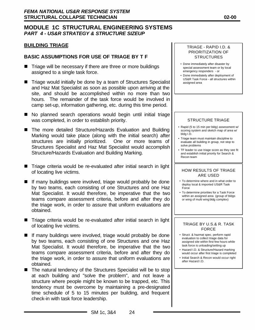
BUILDING TRIAGE
BASIC ASSUMPTIONS FOR USE OF TRIAGE BY T F
n Triage will be necessary if there are three or more buildingsassigned to a single task force.
n Triage would initially be done by a team of Structures Specialistand Haz Mat Specialist as soon as possible upon arriving at thesite, and should be accomplished within no more than twohours. The remainder of the task force would be involved incamp set-up, information gathering, etc. during this time period.
TRIAGE - RAPID I.D. &PRIORITIZATION OF
STRUCTURES
• Done immediately after disaster byspecial assessment team or by localemergency responders - or
• Done immediately after deployment ofUS&R Task Force - all structures withinassigned area
n No planned search operations would begin until initial triagewas completed, in order to establish priority.
n The more detailed Structure/Hazards Evaluation and BuildingMarking would take place (along with the initial search) afterstructures are initially prioritized. One or more teams ofStructures Specialist and Haz Mat Specialist would accomplishStructure/Hazards Evaluation and Building Marking.
STRUCTURE TRIAGE
• Rapid (5 to 15 min per bldg) assessment w/scoring system and sketch map of area w/bldg I.D.
• Triage team must maintain discipline toevaluate all building in group, not stop tosolve problems
• TF leader to use triage score as they see fitand establish initial priority for Search &Recon team
n Triage criteria would be re-evaluated after initial search in lightof locating live victims.
n If many buildings were involved, triage would probably be doneby two teams, each consisting of one Structures and one HazMat Specialist. It would therefore, be imperative that the twoteams compare assessment criteria, before and after they dothe triage work, in order to assure that uniform evaluations areobtained.
HOW RESULTS OF TRIAGEARE USED
• To determine where and in what order todeploy local & imported US&R TaskForce
• To determine priorities for a Task Forcewithin an assigned area (group of bldgsor wing of multi wing bldg complex)
n Triage criteria would be re-evaluated after initial search in lightof locating live victims.
n If many buildings were involved, triage would probably be doneby two teams, each consisting of one Structures and one HazMat Specialist. It would therefore, be imperative that the twoteams compare assessment criteria, before and after they dothe triage work, in order to assure that uniform evaluations areobtained.
n The natural tendency of the Structures Specialist will be to stopat each building and "solve the problem", and not leave astructure where people might be known to be trapped, etc. Thistendency must be overcome by maintaining a pre-designatedtime schedule of 5 to 15 minutes per building, and frequentcheck-in with task force leadership.
TRIAGE BY U.S.& R. TASKFORCE
• Struct. & hazmat spec. perform rapidevaluation to collect triage data forassigned site within first few hours whiletask force is unloading/setting up
• Hazard I.D. & Structure/Hazard markingwould occur after first triage is completed
• Initial Search & Recon would occur rightafter Hazard I.D.
FEMA NATIONAL US&R RESPONSE SYSTEMSTRUCTURAL COLLAPSE TECHNICIAN 02-00
MODULE 1C STRUCTURAL ENGINEERING SYSTEMSPART 4 - US&R STRATEGY & STRUCTURE SIZEUP
SM 1c, 3&4 25
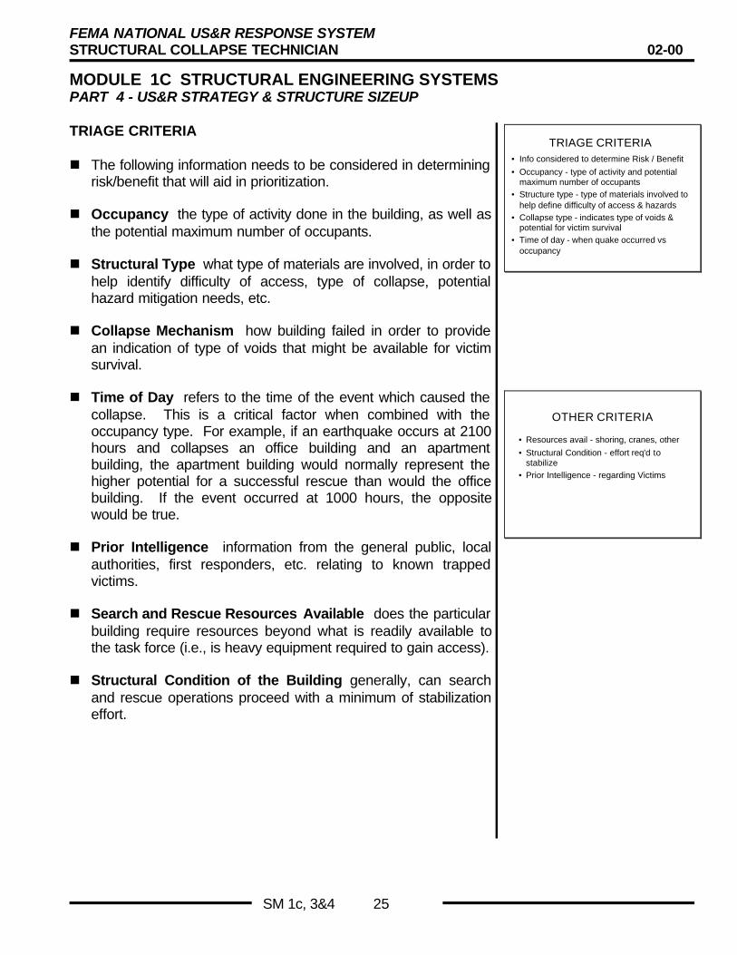
TRIAGE CRITERIA
n The following information needs to be considered in determiningrisk/benefit that will aid in prioritization.
n Occupancy the type of activity done in the building, as well asthe potential maximum number of occupants.
n Structural Type what type of materials are involved, in order tohelp identify difficulty of access, type of collapse, potentialhazard mitigation needs, etc.
n Collapse Mechanism how building failed in order to providean indication of type of voids that might be available for victimsurvival.
TRIAGE CRITERIA• Info considered to determine Risk / Benefit
• Occupancy - type of activity and potentialmaximum number of occupants
• Structure type - type of materials involved tohelp define difficulty of access & hazards
• Collapse type - indicates type of voids &potential for victim survival
• Time of day - when quake occurred vsoccupancy
n Time of Day refers to the time of the event which caused thecollapse. This is a critical factor when combined with theoccupancy type. For example, if an earthquake occurs at 2100hours and collapses an office building and an apartmentbuilding, the apartment building would normally represent thehigher potential for a successful rescue than would the officebuilding. If the event occurred at 1000 hours, the oppositewould be true.
n Prior Intelligence information from the general public, localauthorities, first responders, etc. relating to known trappedvictims.
n Search and Rescue Resources Available does the particularbuilding require resources beyond what is readily available tothe task force (i.e., is heavy equipment required to gain access).
n Structural Condition of the Building generally, can searchand rescue operations proceed with a minimum of stabilizationeffort.
OTHER CRITERIA
• Resources avail - shoring, cranes, other
• Structural Condition - effort req'd tostabilize
• Prior Intelligence - regarding Victims
FEMA NATIONAL US&R RESPONSE SYSTEMSTRUCTURAL COLLAPSE TECHNICIAN 02-00
MODULE 1C STRUCTURAL ENGINEERING SYSTEMSPART 4 - US&R STRATEGY & STRUCTURE SIZEUP
SM 1c, 3&4 26
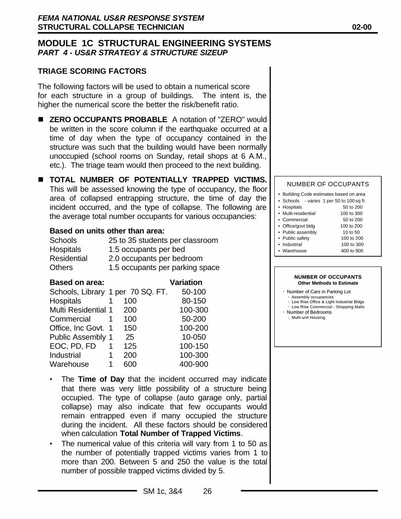
TRIAGE SCORING FACTORS
The following factors will be used to obtain a numerical scorefor each structure in a group of buildings. The intent is, thehigher the numerical score the better the risk/benefit ratio.
n ZERO OCCUPANTS PROBABLE A notation of "ZERO" wouldbe written in the score column if the earthquake occurred at atime of day when the type of occupancy contained in thestructure was such that the building would have been normallyunoccupied (school rooms on Sunday, retail shops at 6 A.M.,etc.). The triage team would then proceed to the next building.
n TOTAL NUMBER OF POTENTIALLY TRAPPED VICTIMS.This will be assessed knowing the type of occupancy, the floorarea of collapsed entrapping structure, the time of day theincident occurred, and the type of collapse. The following arethe average total number occupants for various occupancies:
Based on units other than area:Schools 25 to 35 students per classroomHospitals 1.5 occupants per bedResidential 2.0 occupants per bedroomOthers 1.5 occupants per parking space
Based on area: VariationSchools, Library 1 per 70 SQ. FT. 50-100Hospitals 1 100 80-150Multi Residential 1 200 100-300Commercial 1 100 50-200Office, Inc Govt. 1 150 100-200Public Assembly 1 25 10-050EOC, PD, FD 1 125 100-150Industrial 1 200 100-300Warehouse 1 600 400-900
• The Time of Day that the incident occurred may indicatethat there was very little possibility of a structure beingoccupied. The type of collapse (auto garage only, partialcollapse) may also indicate that few occupants wouldremain entrapped even if many occupied the structureduring the incident. All these factors should be consideredwhen calculation Total Number of Trapped Victims.
• The numerical value of this criteria will vary from 1 to 50 asthe number of potentially trapped victims varies from 1 tomore than 200. Between 5 and 250 the value is the totalnumber of possible trapped victims divided by 5.
NUMBER OF OCCUPANTS
• Building Code estimates based on area• Schools - varies 1 per 50 to 100 sq ft• Hospitals 50 to 200• Multi-residential 100 to 300• Commercial 50 to 200• Office/govt bldg 100 to 200• Public assembly 10 to 50• Public safety 100 to 200• Industrial 100 to 300• Warehouse 400 to 900
NUMBER OF OCCUPANTSNUMBER OF OCCUPANTSOther Methods to EstimateOther Methods to Estimate
•• Number of Cars in Parking LotNumber of Cars in Parking Lot–– Assembly occupanciesAssembly occupancies–– Low Rise Office & Light Industrial BldgsLow Rise Office & Light Industrial Bldgs–– Low Rise Commercial - Shopping MallsLow Rise Commercial - Shopping Malls
•• Number of BedroomsNumber of Bedrooms–– Multi-unit HousingMulti-unit Housing
FEMA NATIONAL US&R RESPONSE SYSTEMSTRUCTURAL COLLAPSE TECHNICIAN 02-00
MODULE 1C STRUCTURAL ENGINEERING SYSTEMSPART 4 - US&R STRATEGY & STRUCTURE SIZEUP
SM 1c, 3&4 27
TRIAGE SCORING FACTORS (continued)
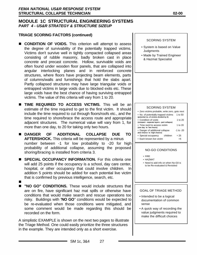
n CONDITION OF VOIDS. This criterion will attempt to assessthe degree of survivability of the potentially trapped victims.Victims don't survive well in tightly compacted collapsed areasconsisting of rubble masonry, badly broken cast in placeconcrete and precast concrete. Hollow, survivable voids areoften found under wooden floor panels, that are collapsed intoangular interlocking planes and in reinforced concretestructures, where floors have projecting beam elements, partsof columns/walls and furnishings that hold the slabs apart.Partly collapsed structures may have large triangular voids orentrapped victims in large voids due to blocked exits etc. Theselarge voids have the best chance of having surviving entrappedvictims. The value of this criteria will vary from 1 to 20.
SCORING SYSTEM
• System is based on ValueJudgments
• Made by Trained Engineer& Hazmat Specialist
SCORING SYSTEM• Zero victims probable, write zero, goto next• No. of potentially trapped victims 1 to 50(potential no. of victims divided by 5)
• Condition of voids 1 to 20(compact - separate layers - part collapse)
• Time req'd to access victim 1 to 20(one day to two hours)
• Danger of additional collapse -1 to -20(low chance to high chance)
• Special occupancy children + 25• Each known live victim +5
n TIME REQUIRED TO ACCESS VICTIMS. This will be anestimate of the time required to get to the first victim. It shouldinclude the time required to cut through floors/roofs etc., and thetime required to shore/brace the access route and appropriateadjacent structures. The numerical value will vary from 1, formore than one day, to 20 for taking only two hours.
n DANGER OF ADDITIONAL COLLAPSE DUE TOAFTERSHOCK. This criteria will be represented by a minusnumber between -1 for low probability to -20 for highprobability of additional collapse, assuming the proposedshoring/bracing is installed from criteria 3.
n SPECIAL OCCUPANCY INFORMATION. For this criteria onewill add 25 points if the occupancy is a school, day care center,hospital, or other occupancy that could involve children. Inaddition 5 points should be added for each potential live victimthat is confirmed by previous intelligence, search, etc.
n
NO-GO CONDITIONS
• FIRE• HAZMAT• Need to add info on when No-G0 is
to be Re-evaluated & Revisited
n "NO GO" CONDITIONS. These would include structures thatare on fire, have significant haz mat spills or otherwise haveconditions that would make search and rescue operations toorisky. Buildings with "NO GO" conditions would be expected tobe re-evaluated when those conditions were mitigated, andsome comment would be made regarding this should berecorded on the form.
A simplistic EXAMPLE is shown on the next two pages to illustratethe Triage Method. One could easily prioritize the three structuresin the example. They are intended only as a short exercise.
GOAL OF TRIAGE METHOD
• Intended to be a logicaldocumentation of commonsense
• A quick way of recording thevalue judgments required tomake the difficult choices

FEMA NATIONAL US&R RESPONSE SYSTEMSTRUCTURAL COLLAPSE TECHNICIAN 02-00
MODULE 1C STRUCTURAL ENGINEERING SYSTEMSPART 4 - US&R STRATEGY & STRUCTURE SIZEUP
SM 1c, 3&4 28
EXAMPLE STRUCTURE TRIAGE FOR SUNDAY EARTHQUAKE
FEMA NATIONAL US&R RESPONSE SYSTEMSTRUCTURAL COLLAPSE TECHNICIAN 02-00
MODULE 1C STRUCTURAL ENGINEERING SYSTEMSPART 4 - US&R STRATEGY & STRUCTURE SIZEUP
SM 1c, 3&4 29
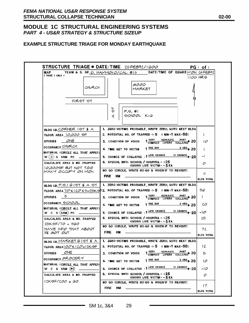
EXAMPLE STRUCTURE TRIAGE FOR MONDAY EARTHQUAKE

FEMA NATIONAL US&R RESPONSE SYSTEMSTRUCTURAL COLLAPSE TECHNICIAN 02-00
MODULE 1C STRUCTURAL ENGINEERING SYSTEMSPART 4 - US&R STRATEGY & STRUCTURE SIZEUP
SM 1c, 3&4 30
SEARCH AND RECON TEAM
This group of TF members is comprised of the NINE individualslisted in the adjacent slide. A TF can field two of these groups, andmight need to do so if they were faced with the task of locatingvictims in more than one building. The Rescue Specialist involvedon the team could be asked to perform any of the following SearchFunctions: (in addition to his normal Rescue duties)
n Help setup and operate Technical Search Equipment.n Cut access holes for equipment and evaluationn Perform visual and vocal Physical Searchn Help spot for K-9 searchn Help with Hazmat Assessment
SEARCH & RECON TEAM
• nine members (in each of 2 teams on TF)
• search manager• canine search spec (2)• tech search spec• structural spec
• hazmat spec• medical spec• rescue spec (2)
SEARCH & RECON - INITIAL TASKS
As noted in the adjacent slide, the Initial Tasks involve collectingthe data that will help define the US&R Problem.
n Where is it, What is it and What are the details?n What was the Original Configuration and Has it reached a new
State of Equilibrium?n What are our current Problems – Define/Evaluate the Hazardsn How best to remove Victims without creating new ones?
S&R TEAM INITIAL TASKS
• Area plot plan/map and bldg i.d. if notriage
• Structural/Hazard evaluation & marking• Bldg sketch/plan + bldg cross-section
• Bldg config. & type, inc size & no. stories• Collapse type, void location, hazard
location
• Best victim access, hazard mitigation, etc.
RECON & HASTY SEARCH
As previously stated, it is best to proceed by taking nothing forgranted. Do an independent Search & Evaluations
n The most appropriate search tool will depend on the situation.Redundancy for conformation is VERY important.
n Physical search with Hailing would normally be tried first. Acombination may follow.
n A combination that has been effective is to DETECT victimswith Electronics, LOCATE using K9 and/or Physical, andASSESS the victim and confined space with Searchcam/Fibercameras
SEARCH & RECON – FOLLOWING FIRST BUILDING
After finding live victims in the first building, In the situation wherenumerous building are involved, a decision must be made by TFleadership regarding deployment of the Search & Recon Team.
n Should Search & Recon proceed to determine victim viability inother structures, or stay to aid Rescue Operations?
S&R TEAM HASTY SEARCHS&R TEAM HASTY SEARCH
•• Find/remove lightly trappedFind/remove lightly trapped( not likely for TF )( not likely for TF )
•• Use most appropriate search tools firstUse most appropriate search tools first
•• Use redundancy for confirmation -Use redundancy for confirmation -if practicableif practicable
•• Start rescue operations - if appropriateStart rescue operations - if appropriate
•• Report to TFL - re-evaluate priorities vsReport to TFL - re-evaluate priorities vsunsearched, next lower priority buildingunsearched, next lower priority building
DIFFICULT DECISION FORTFL
• Should Search & Recon team leavetheir first building as Rescue Ops arebeginning in order to evaluate thenext priority structure
• Do Rescue Ops need the continuedsupport of Structure & Search Spec
FEMA NATIONAL US&R RESPONSE SYSTEMSTRUCTURAL COLLAPSE TECHNICIAN 02-00
MODULE 1C STRUCTURAL ENGINEERING SYSTEMSPART 4 - US&R STRATEGY & STRUCTURE SIZEUP
SM 1c, 3&4 31
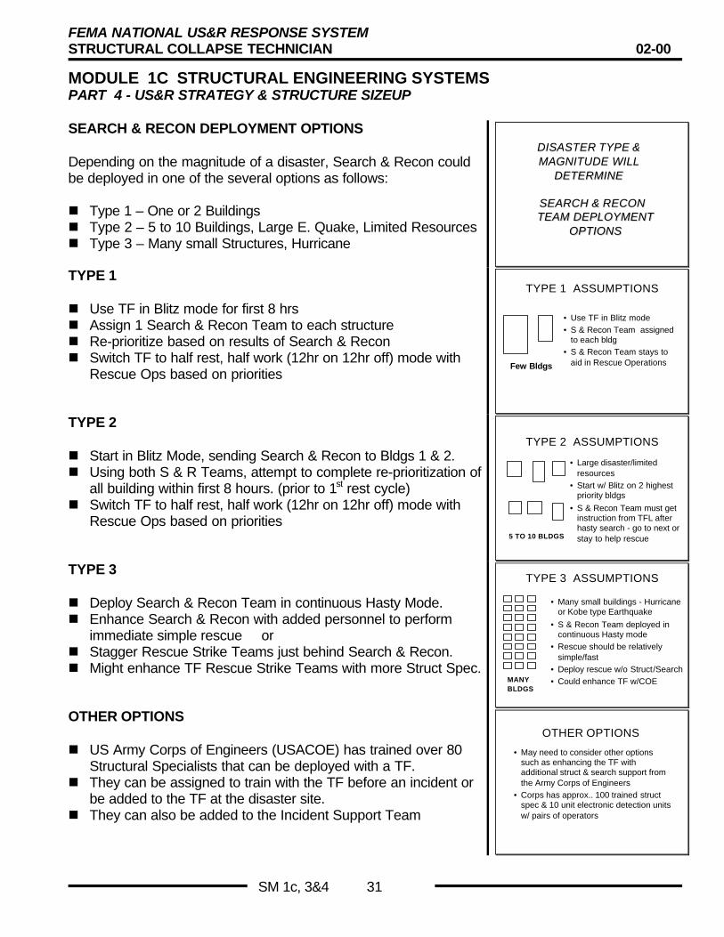
SEARCH & RECON DEPLOYMENT OPTIONS
Depending on the magnitude of a disaster, Search & Recon couldbe deployed in one of the several options as follows:
n Type 1 – One or 2 Buildingsn Type 2 – 5 to 10 Buildings, Large E. Quake, Limited Resourcesn Type 3 – Many small Structures, Hurricane
DISASTER TYPE &DISASTER TYPE &MAGNITUDE WILLMAGNITUDE WILL
DETERMINEDETERMINE
SEARCH & RECONSEARCH & RECONTEAM DEPLOYMENTTEAM DEPLOYMENT
OPTIONSOPTIONS
TYPE 1
n Use TF in Blitz mode for first 8 hrsn Assign 1 Search & Recon Team to each structuren Re-prioritize based on results of Search & Reconn Switch TF to half rest, half work (12hr on 12hr off) mode with
Rescue Ops based on priorities
TYPE 1 ASSUMPTIONS
• Use TF in Blitz mode• S & Recon Team assigned
to each bldg• S & Recon Team stays to
aid in Rescue OperationsFew Bldgs
TYPE 2
n Start in Blitz Mode, sending Search & Recon to Bldgs 1 & 2.n Using both S & R Teams, attempt to complete re-prioritization of
all building within first 8 hours. (prior to 1st rest cycle)n Switch TF to half rest, half work (12hr on 12hr off) mode with
Rescue Ops based on priorities
TYPE 2 ASSUMPTIONS
• Large disaster/limitedresources
• Start w/ Blitz on 2 highestpriority bldgs
• S & Recon Team must getinstruction from TFL afterhasty search - go to next orstay to help rescue5 TO 10 BLDGS
TYPE 3
n Deploy Search & Recon Team in continuous Hasty Mode.n Enhance Search & Recon with added personnel to perform
immediate simple rescue orn Stagger Rescue Strike Teams just behind Search & Recon.n Might enhance TF Rescue Strike Teams with more Struct Spec.
TYPE 3 ASSUMPTIONS
• Many small buildings - Hurricaneor Kobe type Earthquake
• S & Recon Team deployed incontinuous Hasty mode
• Rescue should be relativelysimple/fast
• Deploy rescue w/o Struct/Search• Could enhance TF w/COEMANY
BLDGS
OTHER OPTIONS
n US Army Corps of Engineers (USACOE) has trained over 80Structural Specialists that can be deployed with a TF.
n They can be assigned to train with the TF before an incident orbe added to the TF at the disaster site.
n They can also be added to the Incident Support Team
OTHER OPTIONS
• May need to consider other optionssuch as enhancing the TF withadditional struct & search support fromthe Army Corps of Engineers
• Corps has approx.. 100 trained structspec & 10 unit electronic detection unitsw/ pairs of operators
FEMA NATIONAL US&R RESPONSE SYSTEMSTRUCTURAL COLLAPSE TECHNICIAN 02-00
MODULE 1C STRUCTURAL ENGINEERING SYSTEMSPART 4 - US&R STRATEGY & STRUCTURE SIZEUP
SM 1c, 3&4 32
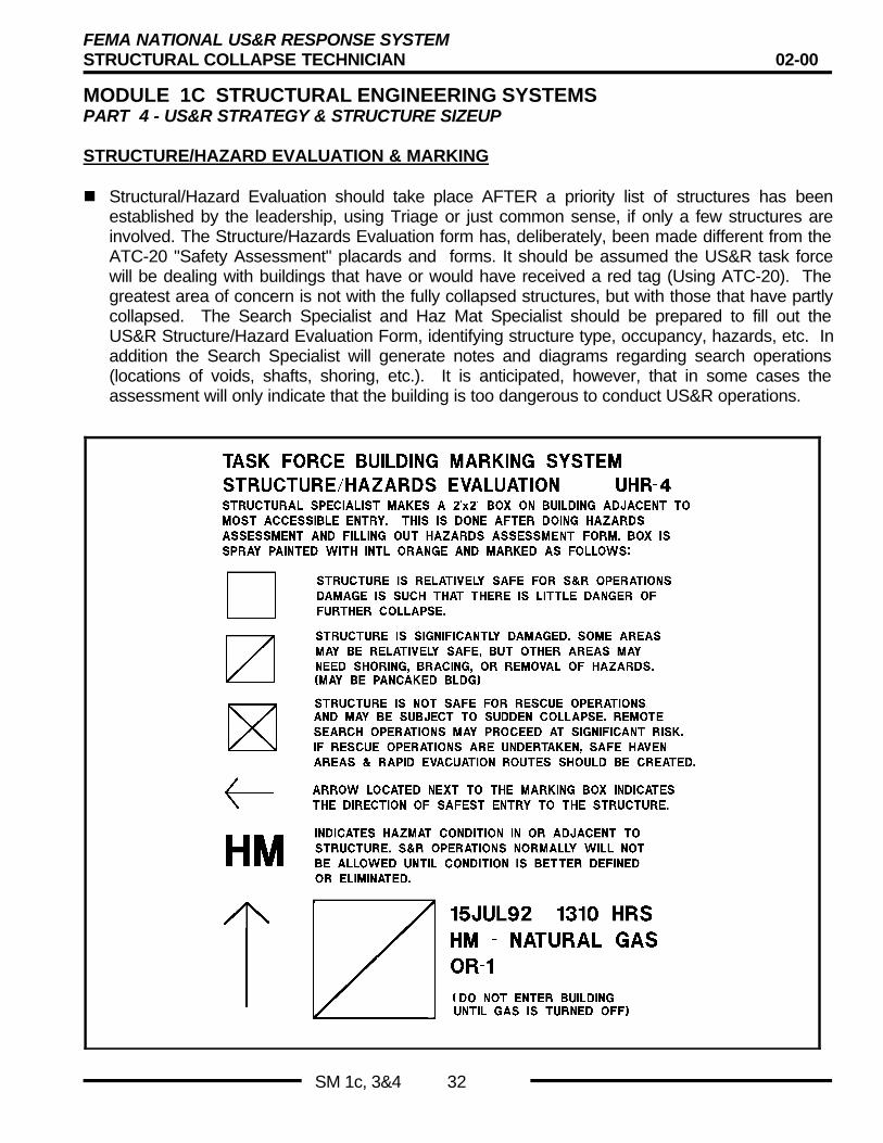
STRUCTURE/HAZARD EVALUATION & MARKING
n Structural/Hazard Evaluation should take place AFTER a priority list of structures has beenestablished by the leadership, using Triage or just common sense, if only a few structures areinvolved. The Structure/Hazards Evaluation form has, deliberately, been made different from theATC-20 "Safety Assessment" placards and forms. It should be assumed the US&R task forcewill be dealing with buildings that have or would have received a red tag (Using ATC-20). Thegreatest area of concern is not with the fully collapsed structures, but with those that have partlycollapsed. The Search Specialist and Haz Mat Specialist should be prepared to fill out theUS&R Structure/Hazard Evaluation Form, identifying structure type, occupancy, hazards, etc. Inaddition the Search Specialist will generate notes and diagrams regarding search operations(locations of voids, shafts, shoring, etc.). It is anticipated, however, that in some cases theassessment will only indicate that the building is too dangerous to conduct US&R operations.
FEMA NATIONAL US&R RESPONSE SYSTEMSTRUCTURAL COLLAPSE TECHNICIAN 02-00
MODULE 1C STRUCTURAL ENGINEERING SYSTEMSPART 4 - US&R STRATEGY & STRUCTURE SIZEUP
SM 1c, 3&4 33
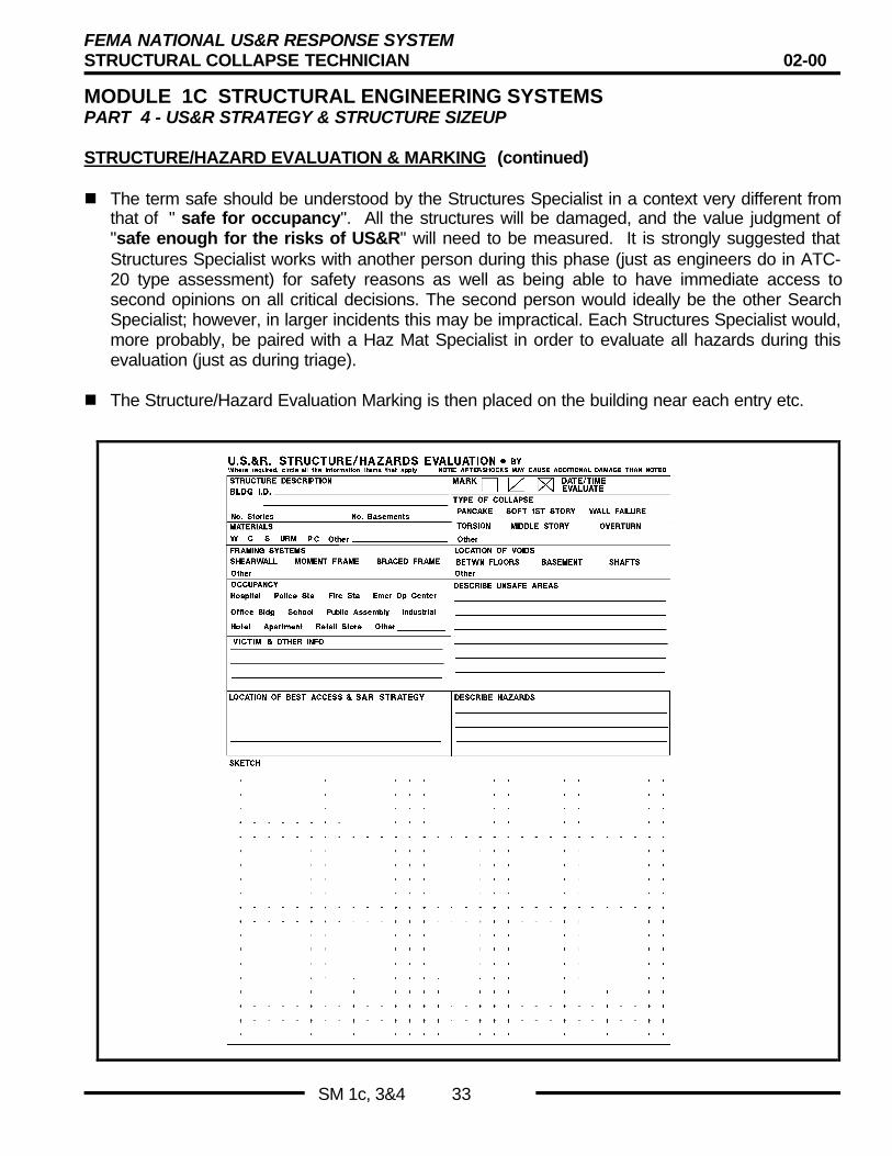
STRUCTURE/HAZARD EVALUATION & MARKING (continued)
n The term safe should be understood by the Structures Specialist in a context very different fromthat of " safe for occupancy". All the structures will be damaged, and the value judgment of"safe enough for the risks of US&R" will need to be measured. It is strongly suggested thatStructures Specialist works with another person during this phase (just as engineers do in ATC-20 type assessment) for safety reasons as well as being able to have immediate access tosecond opinions on all critical decisions. The second person would ideally be the other SearchSpecialist; however, in larger incidents this may be impractical. Each Structures Specialist would,more probably, be paired with a Haz Mat Specialist in order to evaluate all hazards during thisevaluation (just as during triage).
n The Structure/Hazard Evaluation Marking is then placed on the building near each entry etc.

FEMA NATIONAL US&R RESPONSE SYSTEMSTRUCTURAL COLLAPSE TECHNICIAN 02-00
MODULE 1C STRUCTURAL ENGINEERING SYSTEMSPART 4 - US&R STRATEGY & STRUCTURE SIZEUP
SM 1c, 3&4 34
SEARCH & RESCUE ASSESSMENT MARKING
Standard SAR assessment marking is designed to perform two functions:
n First, when SAR personnel enter the building or parts of the building, the initial diagonal line isdrawn so that others will be informed of Aon going operations@.
n When operations are completed in the building (or parts of the building) the crossing diagonalline will be drawn and information added to indicate by whom and what was accomplished.
n The finished mark can then indicate to other SAR forces the outcome of previous operations.

FEMA NATIONAL US&R RESPONSE SYSTEMSTRUCTURAL COLLAPSE TECHNICIAN 02-00
MODULE 1C STRUCTURAL ENGINEERING SYSTEMSPART 4 - US&R STRATEGY & STRUCTURE SIZEUP
SM 1c, 3&4 35
VICTIM MARKING SYSTEM
This series of marks is used to indicate the location of each victimthat is discovered on the US&R site.
n The marks are made with orange spray paint or crayon.
n Marks will normally be initiated after Search is performed unlessthe victim is immediately removed.
n The “V” is intended to be about 2 feet high and located as nearto the victim as practicable.
n It could be painted on a nearby wall surface or directly on apiece of rubble.
n An arrow may be added to indicate the exact victim location.
n The TF identifier Example “CA –6” should be included as shown
n The circle is added when the victim is CONFIRMED.
• As an example the “V” could be placed when only one K9has indicated that a victim has been located, and the circlecould be added when the initial FIND is CONFIRMED byanother K9 or some other search tool.
• It should be noted, however, when K9s are working in pairs,no mark should be made after the first dog indicates a victimbecause it may influence the second dog.
n A horizontal line is added if the victim is confirmed to be dead.
n An large “X” is drawn completely thru the circle after the victimhas been removed
VICTIM LOCATION MARKING
POTENTIALVICTIM
CA 6
CONFIRMEDLIVE VICTIM
CA 6
VICTIM LOCATION MARKING
CONFIRMEDDEAD VICTIM
CA 6
REMOVED VICTIM
CA 6

FEMA NATIONAL US&R RESPONSE SYSTEMSTRUCTURAL COLLAPSE TECHNICIAN 02-00
MODULE 1C STRUCTURAL ENGINEERING SYSTEMSPART 4 - US&R STRATEGY & STRUCTURE SIZEUP
SM 1c, 3&4 36
BASIC BUILDING SEARCH & RESCUE PLANS
BASIC PLAN - FOR INDIVIDUAL BUILDING
n Reconnoiter Site collecting as much information as possible• Determine structure type - to better assess type of failure,
type of hazards, ease of entry and cutting etc.• Interview neighbors, survivors, interested people (how many
potential victims; where last seen, location of stairs,elevators, basement, etc.).
• Obtain building plan an/or draw crude plan with specialemphasis on probable location of voids, existing shafts,basement.
• Search Specialists re-assess building in detail to re-identifyhazards.
n Prioritize site use collected data to obtain best risk/benefitratio.• Conduct callout/listen search.• Plan shoring at access, and/or use most efficient access.• Determine condition of basement.• Avoid falling hazards unless they can be removed and/or
shored.
Basic Approach to US&R
• Identify the Problem– Prioritize
• Find Victims– Re-prioritize
• Remove Victims– Medically stabilize
• Create NO NEW VICTIMS
Basic Building SAR Plan(initial phases)
• Reconnoiter– determine structure type
– obtain / draw plans
– access hazards
– interview neighbors, etc.
• Prioritize Site– develop hazard mitigation alternatives
– callout / listen search
– condition of voids & basement
n Initial Search Appendix C, FEMA US&R ResponseSystem, Search Strategy & Tactics, addresses this subject.Properly trained search dogs and electronic locators have beenused successfully in US&R to locate deeply buried victims.Both have significant limitations, i.e., the dogs must berepeatedly trained in the rubble environment in order toeffectively find human scent, not be concerned about their ownsafety, and to ignore animal, food, and/or sewer gases. Evenproperly trained dogs may only be able to indicate direction ofscent, which is not necessarily the direction of the victim.
n Electronic devices, even when operated by trained personnel,may be only able to detect victims that are very activelysending tapping signals.• Use search dogs with "send out" as far as possible into
structure. Check alerts with second dog/observer/handler.• Use listening/seismic finders if available.• Explore existing vertical shaft openings if available.• Explore horizontal openings with great care (send dog in
and keep people out if practical).• In general search from safe, stable areas into unstable.• Re-prioritize site vs. location of potential live victims.
Basic Building SAR Plan(initial phases)
• Initial Search– use K-9 in safe & less safe areas
– use technical search equip.
– use existing vertical shaft opngs
– use existing horizontal opngs with greatcare
– search from stable to un-stable
– re-prioritize vs live finds
FEMA NATIONAL US&R RESPONSE SYSTEMSTRUCTURAL COLLAPSE TECHNICIAN 02-00
MODULE 1C STRUCTURAL ENGINEERING SYSTEMSPART 4 - US&R STRATEGY & STRUCTURE SIZEUP
SM 1c, 3&4 37
BASIC PLAN - FOR INDIVIDUAL BUILDING
n Selected Cutting & Removal based on priorities of initialsearch vs. probable hazards.• Cut vertical openings and re-search, re-check with dogs
and/or listening/viewing devices.• Initial shoring for access.• Avoid un-shored overhead structures.• Recheck all shoring after cutting and removal, loading can
change.• Continue process of cutting layers, re-searching, and re-
prioritizing.• Stabilize area at victim to give medical aid.
Basic Building SAR Plan(main phase - days long ?)
• Selected cutting / removal– cut vert opngs & re-search
– initial shoring for access
– avoid unshored overhead slabs, etc.
– re-check shoring after cutting & removal
– continue - cut opng & re-search
– shore victim area for rescue ops
– Struc Spec gives continuing aid to rescue
n Heavy Search & Rescue• Continue search after prolonged cutting and/or removal.• Give victim aid and gain information regarding additional
victims.• Re-check all shoring after cutting and removal, since loading
can change
SAR PLAN - LIGHT FRAME BUILDINGS
Quick Review of SAR Plans
• Light Frame
• Heavy Wall– URM And TU
• Heavy Floor– Concrete frame
• Precast Concrete
• Discuss cutting for victim access
n Search Items
• Callout/listen search may be effective due to lower density ofwood floors.
• Acoustic listening devices will probably be more effectivethan seismic type sensors in these buildings that have woodfloors and walls. Broken wood is relatively poor transmittersof vibrations.
• Dogs may be able to sent through cracks in wood floors ifthey are not heavily covered.
SAR Plan - Light Frame Bldgs
• Search Items– callout/listen search may be effective due to
low density of wood floors.
– acoustic listening devices will probably bemore effective than seismic type in buildingswith wood floors & walls.
– K9 should be able to scent thru cracks inwood floors if they are not heavily covered
n Hazard Reduction Items
• Shut off gas (and electricity) and reduce other fire hazards.(This applies for all types of buildings)
• Assess / refer chemical hazards. (What's in the typicalkitchen?)
• Remove / avoid or topple leaning chimney• Place vertical and / or lateral shores. Leaning multi-story
buildings may be shored using diagonal timbers.
SAR Plan - Light Frame Bldgs
• Hazard Reduction Items– shut off gas & reduce other fire hazard (all)
– assess / refer chemical hazards
– remove / avoid or topple leaning chimney
– place diagonal shores on leaning multi-story
– falling hazards - remove / avoid masonryveneer , etc.

FEMA NATIONAL US&R RESPONSE SYSTEMSTRUCTURAL COLLAPSE TECHNICIAN 02-00
MODULE 1C STRUCTURAL ENGINEERING SYSTEMSPART 4 - US&R STRATEGY & STRUCTURE SIZEUP
SM 1c, 3&4 38
SAR PLAN - LIGHT FRAME BUILDINGS (continued)
n Victim Access Items
• Use horizontal entry thru cavities or thru walls.
• Make vertical access thru holes cut in roof / floor
• Remove / shore hazards as required.
SAR PLAN - HEAVY WALL BUILDINGS - URM & TU
SAR Plan - Light Frame Bldgs
• Victim Access Items– use horizontal entry thru cavities or thru walls
– make vertical access thru hole in roof/floor
– remove/shore hazards as required
n Search Items
• Callout / listen search may be effective due to lower densityof wood floors.
• Acoustic listening devices will probably be more effectivethan seismic type sensors. Most of these structures will havewood floors that have collapsed in large planes and badlybroken masonry, both of which are relatively poortransmitters of vibrations.
• K9 may be able to sent through cracks in wood floors if theyare not heavily covered.
SAR Plan - Heavy Wall Bldg
• Search Items– callout/listen search may be effective due to
low density of wood floors.
– acoustic listening devices will probably bemore effective than seismic type in buildingswith wood floors & badly broken masonrywalls.
– K9 should be able to scent thru cracks inwood floors if they are not heavily covered
n Hazard Reduction Items - URM • Shore hazardous floors with vertical shores.
• Remaining uncollapsed URM walls are brittle, aftershock /wind falling hazards. Either avoid, remove, tieback, or rakershore them. May need to shore in both IN and OUTdirection.
• Beware of all falling hazards - peeled, cracked, & split URMwalls are very brittle. High potential for falling & collapsehazards.
n Hazard Reduction Items - TU & Low Rise
• Use diagonal or raker shores for hazardous walls.
• Shore hazardous roof / floor beams, etc.
SAR Plan - Heavy Wall BldgSAR Plan - Heavy Wall Bldg•• Hazard reduction items - URMHazard reduction items - URM
–– shore hazardous floorsshore hazardous floors–– remaining, uncollapsed walls may beremaining, uncollapsed walls may be
aftershock falling hazard. either avoid,aftershock falling hazard. either avoid,remove, tieback, or raker shore them. mayremove, tieback, or raker shore them. mayneed to shore both in and out direction.need to shore both in and out direction.
–– beware of all falling hazards - peeled,beware of all falling hazards - peeled,cracked, & split urm walls are very brittle.cracked, & split urm walls are very brittle.high potential of falling & collapse hazardshigh potential of falling & collapse hazards
•• Hazard reduction items - TU & Low RiseHazard reduction items - TU & Low Rise–– raker shore hazardous wallsraker shore hazardous walls–– shore hazardous roof/floor beamsshore hazardous roof/floor beams

FEMA NATIONAL US&R RESPONSE SYSTEMSTRUCTURAL COLLAPSE TECHNICIAN 02-00
MODULE 1C STRUCTURAL ENGINEERING SYSTEMSPART 4 - US&R STRATEGY & STRUCTURE SIZEUP
SM 1c, 3&4 39
SAR PLAN - HEAVY WALL BUILDINGS - URM & TU (cont.)
n Victim Access Items - URM
• Use horizontal entry thru existing openings with great care.
• Vertical access through wood floors should be easy andleast dangerous.
• Avoid cutting large beams and more than two joists in a row.
• Avoid cutting walls. Holes can greatly reduce strength ofpoorly cemented walls - most are important bearing walls
• Beware of roof / floor joist / beams that are not sitting ontheir original flat bearings or ledges, they can slide downwalls and produce outward forces as they move to find nextstable position.
• Basement may provide good access, but should shore forsafety. Failure of wood column or beams can be sudden.
• Hand removal of bricks may be required.
• Large pieces of wall may be removed by clamshell or otherbucket with thumb. ( need to prevent parts from falling)
SAR Plan - Heavy Wall Bldg• Victim Access Items URM
– use horizontal entry thru existing openings
– make vertical access thru hole in roof/floor,avoid cutting beams & more than 2 joist in arow
– avoid cutting walls. holes greatly reducestrength of URM walls - are importantbearing walls.
– beware of roof/floor joist & beams that arenot resting on their original bearings. theycould slide down walls and produce outwardforces as they move down.
SAR Plan - Heavy Wall Bldg
• Victim Access Items URM continued– basements may provide good access but
should shore floor above for safety. failure ofwood post or beams could be sudden.
– hand removal of bricks may be required
– large wall pieces may need to be removed bycrane/clamshell bucket (parts may fall)
n Victim Access Items - TU & Low Rise
• Use horizontal entry thru existing openings with great care.
• Vertical access through wood roof / floors should be easyand least dangerous.
• Holes in wall panels should best be made 2 ft min awayfrom joints. If wall has concrete pilaster / column, one maycut opening next to column on side away from joint.
• Wall panels and large pieces of roof may be lifted by craneor other equipment.
SAR Plan - Heavy Wall Bldg
• Victim Access Items TU & Low rise– use horizontal entry thru existing openings
– make vertical access thru hole in roof/floor
– holes in wall panels should be made awayfrom joints (next to columns O.K..)
– wall panels and/or large sections of roof/floorcan be lifted by crane

FEMA NATIONAL US&R RESPONSE SYSTEMSTRUCTURAL COLLAPSE TECHNICIAN 02-00
MODULE 1C STRUCTURAL ENGINEERING SYSTEMSPART 4 - US&R STRATEGY & STRUCTURE SIZEUP
SM 1c, 3&4 40
SAR PLAN - CONCRETE FRAME BUILDINGS
n Search Items - Heavy Floor
• Not likely to hear callout of victims through floors due to highdensity of concrete.
• Seismic listening devices can be most effective in these,heavy structures, especially when floor slabs remain intactand form thin void spaces as in pancake type collapse.
• K9 will indicate direction of scent which may be flowingaround large slabs, back and forth across the building.(Location of victim must be interpreted from conditions)Area should be re-checked by dogs after layers have beenremoved. Best time to use dogs C in early morning and atdusk C scent is rising.
SAR Plan - Conc Frame Bldg
• Search Items– callout/listen search may not be effective due
to high density of concrete floors.
– seismic listening devices can be mosteffective, especially when large floor slabsremain intact to form thin void spaces inpancake type collapse
– K9 will indicate direction of scent which maybe flowing around large slabs, back and forthacross building• location of victim is interpreted by handler.
best time for K9 is early a.m. and at dusk
n Hazard Reduction Items - Heavy Floor
• In partly collapsed building (upper floors, etc.) is veryimportant to check floors that support debris load.- read cracks to determine if more and progressive
collapse is probable.
- multi-story shoring may be only safe procedure.
- it normally takes at least two un-damaged floors tosupport shores from one damaged floor that containslittle debris (if heavy concrete debris from upper floors ispresent, shores need to extend down to additional,undamaged floors - two more floors per 12" of debris)
• Shore / avoid badly cracked beams.
• Shore / avoid hanging slabs / beams.
• Shore heavily loaded flat slabs (beamless slabs) - punchingshear.
• Beware of all falling hazards - parts of slabs, walls, etc. Maybe hanging from exposed rebar - how well is rebarembedded?
• Monitor structure for Lateral Movement with Theodolite orother tilt measuring device
SAR Plan - Conc Frame Bldg• Hazard reduction items
– in partly collapsed bldg - very important tocheck the floor that supports the collapsedebris. read cracks to determine if additionalcollapse is probable. heavy, multi story shoringmay be only safe procedure.
– shore/avoid badly cracked beams/columns
– shore/avoid hanging slabs/beams
– shore/avoid heavily loaded slabs (punching)
– beware of all falling hazards - many parts ofconcrete slabs, walls, etc. may be hanging fromexposed rebar - how well connected

FEMA NATIONAL US&R RESPONSE SYSTEMSTRUCTURAL COLLAPSE TECHNICIAN 02-00
MODULE 1C STRUCTURAL ENGINEERING SYSTEMSPART 4 - US&R STRATEGY & STRUCTURE SIZEUP
SM 1c, 3&4 41
SAR PLAN - CONCRETE FRAME BUILDINGS (continued)
n Victim Access Items - Heavy Floor
• Use any existing vertical shaft.
• Basement may be good access, but need to evaluate floorslab above and possibly shore. How many basementlevels?
• Preferred access is usually made by cutting thru slabs fromabove collapse.
• Best to cut slabs mid-way between beams & columns.
• Check for thinnest slab area. Pan joist and waffle slabs haveribs spaced 3 ft or so with 3 to 4 inch thick slab between.
• Do not cut columns - usually do not need to.
• Avoid cutting concrete / masonry walls. They may bebearing walls. If have masonry infill wall in concrete framecutting is possible - check first to see if frame is loading walldue to collapse.
• Remove concrete slabs with Crane after all rebar is cut
SAR PLAN - PRECAST CONCRETE BUILDINGS
n Search Items - Precast Concrete
• Callout / listen search may be effective. It depends on sizeof voids between larger pieces of concrete.
• Effectiveness of listening devices will depend on theinterconnection of the collapsed, structural parts. Acousticsensors may not be effective in compact rubble, and seismicsensors may not be effective due to poor transfer throughbadly broken concrete parts.
• K9 search may be effective - again depending oncompactness of concrete rubble.
SAR Plan - Conc Frame Bldg
• Victim Access Items– use any existing vertical access shaft
– basement may be good unobstructed accessbut must evaluate floor slab above and shore ifreq'd.
– preferred access is most often cutting slabsfrom above collapse.
– best to cut slabs mid-way between beams andor columns
SAR Plan - Conc Frame Bldg
• Victim Access Items - continued– check for thinnest slab areas. (pan joist &
waffle slabs may have ribs up to 3 feet apart)
– do not cut columns - usually do not need to
– avoid cutting concrete walls - they may bemajor bearing walls. some frames may haveurm infill walls that may be cut - check first asthey may be loaded due to collapse.
– Remove concrete slabs with Crane after allrebar is cut
SAR Plan - Precast Conc Bldg• Search Items
– callout/listen search may be effective -depends on how compact is rubble .
– effectiveness of listening devices will dependon the interconnection of the collapsed,structural parts - acoustic sensors may not beeffective in compact rubble & seismic may notbe effective due to poor transfer thru badlybroken concrete parts.
– K9 may be able to scent thru openings indebris, depends on compactness of rubble.
FEMA NATIONAL US&R RESPONSE SYSTEMSTRUCTURAL COLLAPSE TECHNICIAN 02-00
MODULE 1C STRUCTURAL ENGINEERING SYSTEMSPART 4 - US&R STRATEGY & STRUCTURE SIZEUP
SM 1c, 3&4 42
SAR PLAN - PRECAST CONCRETE BUILDINGS (continued)
n Hazard Reduction Items - Precast Concrete
• Remove / avoid hanging pieces of structure. There may bemany loose or poorly connected pieces of precast concrete.Use cranes and other equipment.
• Shore beams adjacent to badly cracked columns.
• Remove / shore tilted wall panels or pieces.
• Partly collapsed buildings may have adjacent slabs and/orwall panels that have damaged connections that may breakloose in aftershocks or if loading shifts.
n Victim Access Items - Precast Concrete
• Cutting of cored slabs & tee slabs should be done at edges(Thru thinnest part of section and away from ribs).
- cut half of hole in each of two adjacent precast pieces.
• Don't cut ribs in Tees or walls & do not cut columns.
• Walls may be cut with care.- cut holes at least 2 ft away from joints.- consider problems of shoring vs. removal (removal may
be more efficient).- check wall welded joints for signs of movement.- some walls may be infill URM and may be cut if not
loaded by collapsed concrete pieces.
• Basements may not be good access unless basement wallsand first floor slab are cast in place concrete. Shoring maybe required in any case.
• Use horizontal access thru existing cavities - use great care
• Lift off loose concrete pieces with cranes or other equipment
• Great care must be taken when lifting and/or shoring largeconcrete pieces, since adjacent pieces may shift.
• Precast concrete will often weigh about 75% of normal (150PCF) concrete. It also splits more easily.
SAR Plan - Precast Conc Bldg
• Hazard reduction items– remove/avoid hanging pieces/structure
– shore beams adj. to badly cracked columns
– remove/shore tilted panels or pieces
– partly collapsed buildings may have adjacentparts (slabs, wall panels, etc.) that havedamaged connections that may break inaftershock or if loading shifts.
SAR Plan - Precast Conc Bldg
• Victim Access Items– for access thru thin slabs,
• make holes at joints (half hole in each adjoiningpiece)
• avoid cutting ribs in single and double tees.• do not cut columns
– walls may be cut with care.• cut concrete wall panels at least 2 feet away from
joint, if possible.• some walls may be infill URM and may be cut if
not being loaded by collapse.
SAR Plan - Precast Conc Bldg• Victim Access Items continued
– basements may not be good access unlessbasement walls and slab were CIP concrete
– use horizontal access thru existing cavities.
– use cranes to remove large disconnectedconcrete layers.
– great care must be taken when lifting and/orshoring large concrete pieces, adjacent piecesmay shift
– precast concrete weighs about 3/4 as much asnormal concrete. it also splits more easily.
FEMA NATIONAL US&R RESPONSE SYSTEMSTRUCTURAL COLLAPSE TECHNICIAN 02-00
MODULE 1C STRUCTURAL ENGINEERING SYSTEMSPART 4 - US&R STRATEGY & STRUCTURE SIZEUP
SM 1c, 3&4 43
METAL DETECTOR
Hand held metal detectors can be used to locate rebar or prestresscables prior to cutting slabs and walls. This can keep from dullingbits and inadvertently cutting cables.
Metallescanner 6.0 by Zircon is magnetic type that is small and candetermine location of rebar as much as 4” deep. Cost $100Other devices are available with costs from $400 to $2000.
Metal Detector• Needed to keep drill bits from hitting rebar• Also to find posttensioning
• New device by Zircon Corp 1997– Metalliscanner - 6.0 (cost = $100)
– Available from Tool Crib (800) 358-3096
– May be sold at Home Depot/Base, etc
– Micropowered viewer - ?
• More expensive (up to $2000) devicesare available
CUTTING POST TENSIONED CONCRETE
Post-tensioned concrete contains steel cables ( ½” dia.) that areplaced in wet concrete after they are enclosed in a long plasticcasing (sometimes called sheath or sleeve). When the concretehardens, the cables are tensioned by pulling them on one or bothends with a hydraulic jack.
Post-tensioning Cables (P.T.) are then anchored in special steelfittings at each edge of the concrete floor, but remain separatedfrom the concrete by the plastic casing. (un-bonded)
n When P.T. cables need to be cut during US&R Ops, specialcare needs to be taken to deal with the tension force that will bereleased .(normally 25,000 lb)
n Cables are most often placed in a Draped Configuration withinthe concrete. The cable is placed near the bottom of slab /beam near mid-span, and near the top where cables pass oversupporting columns or beams.
n It is best to use a Torch to cut the P.T. cables, since the tensioncan be released slowly. A carbide saw could be used tocarefully cut the cables, one wire at a time.
n If the cable is not cut slowly so that the force can be graduallyreleased, parts of the cable may violently project out of theconcrete structure.
n Depending where the cable is cut it made project above thefloor near their supports, below the floor near mid-span, orproject out of the end /side of the concrete slab like a largespear• Any of these occurrences can severely injure or kill.
n The TF can mitigate this problem by clearing an area thatmeasures, at least, 10 feet either side of the cable for the fulllength of the slab / beam. In addition the area outside thebuilding should be cleared for 100 feet and/or barricaded to dealwith the threat of the cable spear.
Cutting Posttentioned Concrete• Problem of end of slab Pop-Out• Problem of mid-slab cable break-out• PT structures successfully de-constructed• Locate tendon needed to be cut
– clear area 10ft ea side of tendon for full length ofstructure
– clear 100ft and /or add padding device at ends
• Slabs may have 2 way tendons• Slow cut w/ torch or carbide saw
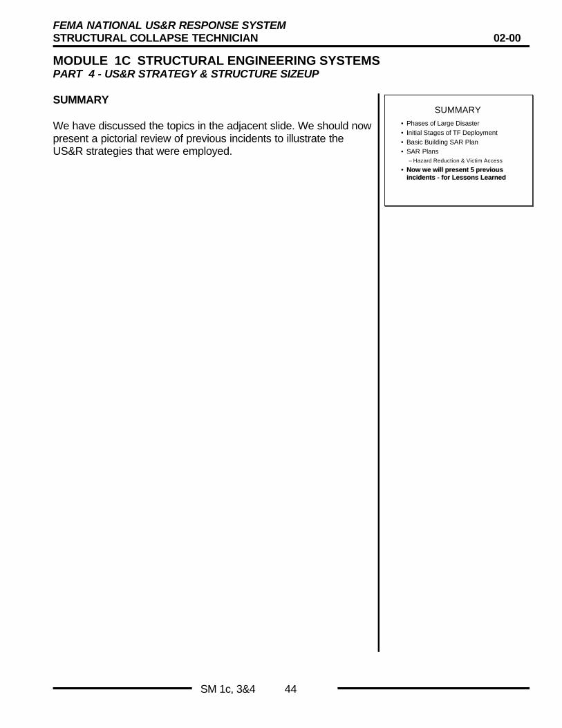
FEMA NATIONAL US&R RESPONSE SYSTEMSTRUCTURAL COLLAPSE TECHNICIAN 02-00
MODULE 1C STRUCTURAL ENGINEERING SYSTEMSPART 4 - US&R STRATEGY & STRUCTURE SIZEUP
SM 1c, 3&4 44
SUMMARY
We have discussed the topics in the adjacent slide. We should nowpresent a pictorial review of previous incidents to illustrate theUS&R strategies that were employed.
SUMMARY• Phases of Large Disaster• Initial Stages of TF Deployment• Basic Building SAR Plan• SAR Plans
– Hazard Reduction & Victim Access
•• Now we will present 5 previousNow we will present 5 previousincidents - for Lessons Learnedincidents - for Lessons Learned