module 18 - above grade masonry · pdf filemodule 18 - above grade masonry 30. as a general...
TRANSCRIPT

© QUEEN’S PRINTER FOR ONTARIO 2013 HOUSE 2012 1.27
MODULE 1 INTRODUCTION AND INSTRUCTIONS
1
MODULE 18 - ABOVE GRADE MASONRY
30. As a general rule, the provisions found in Section 9.20. apply to unreinforced walls that are;
a) up to 11 m high
b) not more than 3 storeys high
c) designed by an architect or an engineer
d) unlimited in height.
Reference:
31. Loadbearing elements in a two storey building of masonry construction are required to have earthquake reinforcement described in Subsection 9.20.15. if the seismic spectral acceleration;
a) Sa(0.2) is not greater than 0.35
b) Sa(0.2) is greater than 0.35
c) Sa(0.2) is not greater than 0.55
d) Sa(0.2) is greater than 0.55
References:
32. A 2 100 mm opening in an exterior masonry wall and supporting 100 mm face brick with no floor load is permitted to be supported by a steel angle lintel comprised of;
a) L-90 × 90 × 6
b) L-125 × 90 × 8
c) L-125 × 125 × 8
d) L-102 × 89 × 7.9
References:
33. The depth of chases located in 190 mm thick masonry walls are limited to;
a) 1/3 of the thickness of the wall
b) 100 mm
c) 75 mm
d) are not permitted.
References:

© QUEEN’S PRINTER FOR ONTARIO 2013 HOUSE 2012 1.29
MODULE 1 INTRODUCTION AND INSTRUCTIONS
1
38. Consider a masonry wall requiring earthquake reinforcement under Article 9.20.1.2. If it is determined that the total amount of reinforcing steel is to be 750 mm², what is the minimum amount of horizontal steel in this case?
a) 250 mm²
b) 250 mm² or 500 mm² with the remainder installed vertically
c) 200 mm²
d) 200 mm² or 550 mm² with the remainder installed vertically
Reference:
39. A 4.76 mm by 40 mm carbon steel strip used to tie intersecting walls is required to have corrosion-resistance which is in accordance with;
a) ASTM A153/A153M and a Class B2 coating
b) ASTM A153/A153M and a coating as per ASTM A153
c) ASTM A123/A123M and a coating of 610 g/m²
d) ASTM A123/A123M and a coating of 305 g/m²
References:
40. The thickness of concrete in flat insulating concrete form walls not in contact with the ground must be constant for the entire height of the wall and not less than:
a) 100 mm
b) 120 mm
c) 140 mm
d) 160 mm
Reference:
MODULE 22 - SHEET STEEL STUD WALL FRAMING
41. What is the maximum wall height for an interior non-loadbearing wall built of 32 × 64 steel studs at 610 mm o.c.?
a) 2.7 m max.
b) 3.5 m max.
c) 4.0 m max.
d) 4.9 m max.
References:

1.30 HOUSE 2012 © QUEEN’S PRINTER FOR ONTARIO 2013
MODULE 1 INTRODUCTION AND INSTRUCTIONS
42. What is the minimum metal thickness of steel studs exclusive of any coatings in an interior non-loadbearing wall with no required fire-resistance rating?
a) 0.46 mm
b) 0.53 mm
c) 0.69 mm
d) 0.85 mm
Reference:
43. What would be the stud size, thickness and spacing for a non-loadbearing exterior wall 3 600 mm high?
a) 30 × 91 × 0.53 @ 300 mm o.c. max.
b) 30 × 91 × 0.85 @ 305 mm o.c. max.
c) 30 × 91 × 0.85 @ 400 mm o.c. max.
d) 30 × 91 × 1.00 @ 400 mm o.c. max.
References:
MODULE 24 - ROOFING
44. The minimum roof slope for low slope application of asphalt shingles is:
a) 1 in 2
b) 1 in 3
c) 1 in 4
d) 1 in 6
References:
45. Eave protection under asphalt shingles applied on slopes of 1 in 3 is to extend up the roof slope a minimum distance of:
a) 300 mm
b) 900 mm
c) 1200 mm
d) 900 mm and at least 300 mm past the inside face of the exterior wall
References:

1.40 HOUSE 2012 © QUEEN’S PRINTER FOR ONTARIO 2013
MODULE 1 INTRODUCTION AND INSTRUCTIONS
6. Mirrored glass doors conforming to CAN/CGSB-82.6-M, “Doors, Mirrored Glass, Sliding or Folding, Wardrobe” and mirrored glass doors reinforced with a film backing that meet the impact resistance requirements specified in CAN/CGSB-12.5-M, “Mirrors, Silvered” may be used:
d) on any door to a reach-in closet
References: Sentences 9.6.1.2.(2) and (3),
MODULE 5 - WINDOWS, DOORS AND SKYLIGHTS
7. Windows may be omitted from a basement recreation room or an unfinished basement when the space is provided with electric lighting
References: Sentence 9.7.2.3.(1) and Row 1 Column 3 of Table 9.7.2.3.
8. The manufacturing standards of glass for windows are found in:
d) Article 9.6.1.2.
9. The double hung windows of the Mitec House have a pane area of approximately 0.39 m². A consideration of Sentence 9.6.1.3.(1) indicates that if the Mitec House was to be constructed in Goderich, the minimum thickness of the factory-sealed IG units would be:
a) 2.5 mm thick
References: Sentence 9.6.1.3.(1) → A-9.6.1.3.(1) and Table A-9.6.1.3.B.
To obtain Climatic Information for Building Design in Ontario, Sentences 1.1.2.1.(1) and 9.4.1.1.(3) → Supplementary Standard SB-1, Table 1.2 Column 14, Goderich has 1/10 Hourly Wind Pressures of 0.43 kPa
MODULE 7 - MEANS OF EGRESS
10. Consider our two-storey MITEC House. The number of required exits is:
a) 1 exit door
Reference: Sentence 9.9.8.2.(1) → Clause 9.9.9.1.(1)(b)
11. An exit door serving our two-storey MITEC House:
c) may swing in the direction of exit travel or inward
Reference: Sentence 9.9.6.5.(1)

1.44 HOUSE 2012 © QUEEN’S PRINTER FOR ONTARIO 2013
MODULE 1 INTRODUCTION AND INSTRUCTIONS
MODULE 18 - ABOVE GRADE MASONRY
30. As a general rule, the provisions found in Section 9.20. apply to unreinforced walls that are;
a) up to 11 m high
Reference: Subclause 9.20.1.1.(1)(a)(i)
31. Loadbearing elements in a two storey building of masonry construction are required to have earthquake reinforcement described in Subsection 9.20.15. if the seismic spectral response acceleration;
d) Sa(0.2) is greater than 0.55
References: Sentence 9.20.1.1.(1) → 9.20.1.2.(1)
32. A 2 100 mm opening in an exterior masonry wall and supporting 100 mm face brick with no floor load is permitted to be supported by a steel angle lintel comprised of;
d) L-102 × 89 × 7.9
References: Sentence 9.20.5.2.(2) and Row 4, Column 2 of Table 9.20.5.2.A.
33. The depth of chases located in 190 mm thick masonry walls are limited to;
b) 100 mm
References: Sentence 9.20.7.1.(1) → 9.20.7.2.(2)
34. As a general rule, individual wire ties for multiple wythe masonry cavity walls are to be spaced at not more than;
b) 900 mm apart horizontally & 400 mm apart vertically
Reference: Sentence 9.20.9.4.(7)
35. In determining the distance between points of lateral support for interior and exterior cavity walls, with wythes of equal thickness, the thickness of the cavity wall is based on;
d) 2/3 the sum of the thicknesses of the wythes
Reference: Clause 9.20.10.1.(3)(a)
36. Corbelling for masonry veneer of rough stone is limited to;
d) the average projection not being more than 1/3 the width of the supporting base
Reference: Sentence 9.20.12.3.(2)

© QUEEN’S PRINTER FOR ONTARIO 2013 HOUSE 2012 1.45
MODULE 1 INTRODUCTION AND INSTRUCTIONS
1
37. In masonry veneer over wood frame walls, weep holes are to be spaced not more than:
d) 800 mm apart
Reference: Clause 9.20.13.8.(1)(b)
38. Consider a masonry wall requiring earthquake reinforcement under Article 9.20.1.2. If it is determined that the total amount of reinforcing steel is to be 750 mm², what is the minimum amount of horizontal steel in this case?
b) 250 mm² or 500 mm² with the remainder installed vertically
Reference: Sentence 9.20.15.1.(1), 750 ÷3
39. A 4.76 mm by 40 mm carbon steel strip used to tie intersecting walls is required to have corrosion-resistance which is in accordance with;
c) ASTM A123/A123M and a coating of 610 g/m²
References: Sentence 9.20.16.1.(1) and Row 3 of Table 9.20.16.1.
40. The thickness of concrete in flat insulating concrete form walls not in contact with the ground must be constant for the entire height of the wall and not less than:
c) 140 mm
Reference: Clause 9.20.17.1.(1)(a)
MODULE 22 - SHEET STEEL STUD WALL FRAMING
41. What is the maximum wall height for an interior non-loadbearing wall built of 32 × 64 steel studs at 610 mm o.c.?
b) 3.5 m max.
References: Sentence 9.24.2.1.(1) and Row 2 Column 3 of Table 9.24.2.1.
42. What is the minimum metal thickness of steel studs exclusive of any coatings in an interior non-loadbearing wall with no required fire-resistance rating?
a) 0.46 mm
Reference: Sentence 9.24.2.2.(1)
43. What would be the stud size, thickness and spacing for a non-loadbearing exterior wall 3 600 mm high?
b) 30 × 91 × 0.85 @ 305 mm o.c. max.
References: Sentence 9.24.2.5.(1) → Row 3, Columns 1, 2 and 3 of Table 9.24.2.5.

1.46 HOUSE 2012 © QUEEN’S PRINTER FOR ONTARIO 2013
MODULE 1 INTRODUCTION AND INSTRUCTIONS
MODULE 24 - ROOFING
44. The minimum roof slope for low slope application of asphalt shingles is:
d) 1 in 6
References: Sentence 9.26.3.1.(1) and Row 3, Column 2 of Table 9.26.3.1.
45. Eave protection under asphalt shingles applied on slopes of 1 in 3 is to extend up the roof slope a minimum distance of:
d) 900 mm and at least 300 mm past the inside face of the exterior wall
References: Sentence 9.26.7.7.(1) → 9.26.5.1.(1)
46. Eave protection under asphalt shingles applied on slopes of 1 in 6 is to extend up the roof slope a minimum distance of:
d) not required when the installation of shingles complies to Subsection 9.26.8.
Reference: Clause 9.26.5.1.(2)(c)
MODULE 25 - CLADDING
47. The minimum length of nails for the attachment of metal siding is:
c) 38 mm
References: Sentence 9.27.5.4.(1) and Row 3, Column 2 of Table 9.27.5.4.
48. The minimum thickness of plywood cladding (face grain parallel to studs at 400 mm o.c.) applied directly to sheathing is:
a) 6 mm
Reference: Sentence 9.27.8.2.(1)
49. The minimum length of nails for the attachment of vinyl siding is:
c) 38 mm
References: Sentence 9.27.12.2.(1) → 9.27.5.4.(1) → Row 3, Column 2 of Table 9.27.5.4., same as metal siding
MODULE 26 - STUCCO
50. The minimum diameter of nails used for the attachment of stucco lath is;
b) 3.2 mm
Reference: Sentence 9.28.3.2.(1)

2.8 HOUSE 2012 © QUEEN’S PRINTER FOR ONTARIO 2013
MODULE 2 BASICS OF STRUCTURAL DESIGN REQUIREMENTS
NOTA BENE: MinimumliveloadsarealsolistedinTable4.1.5.3.,“SpecifiedUniformlyDistributedLiveLoadsonanAreaofFloororRoof”.
EXERCISE # 1 - STRUCTURAL DESIGN REQUIREMENTS AND APPLICATION LIMITATIONS FOR HOUSESThisexerciseisbasedonSubsections9.4.1.to9.4.3.and4.1.5.andMMAHSupplementaryStandardSB-1.Whenprompted,supportyouranswerswithreferences.
1. AsevidencedinDrawingM2:1,inapostandbeamconstructionsystem,mostrepetitivestructuralmembersarespacedmorethan610mmapart.Consequently,theywouldneedtobedesignedinconformancewith:
a) postandbeamsystemisnotpermittedfortheconstructionofHousesbecausetherepetitiveframingmembersarespacedmorethan610mmo.c.
b) goodengineeringpracticesuchasprovidedinCWC’s“EngineeringGuideforWoodFrameConstruction”
c) Part4oftheCodeusingtheloads,deflectionandvibrationlimitsspecifiedinPart9or4
d) Part4oftheCodeusingtheloads,deflectionandvibrationlimitsspecifiedinPart9or4orgoodengineeringpracticesuchasprovidedinCWC’s“EngineeringGuideforWoodFrameConstruction”
References:
2. ConsideraHousemeasuring8mby12m,tobeconstructedinKapuskasing.Thespecifieddesignsnowloadforroofframingis:
a) 2.8kPa
b) 0.3kPa
c) 1.84kPa
d) 1.56kPa
References:
3. WhentheHouseinquestion#2istobeconstructedinHamilton,belowescarpmentandeastofHighway403thespecifieddesignsnowloadforroofframingis:
a) 0.9kPa
b) 0.4kPa
c) 0.895kPa
d) 1.0kPa
References:

2.10 HOUSE 2012 © QUEEN’S PRINTER FOR ONTARIO 2013
MODULE 2 BASICS OF STRUCTURAL DESIGN REQUIREMENTS
7. ConsiderSubclauses9.4.1.1.(1)(c)(i)and(ii)andcompletethefollowingTablebyinsertingtheminimumuniformlydistributedliveload(UDL)forthespecifiedareaoffloorinaHouse.
Use of area of floor minimum UDL Div. B reference1 Atticaccessiblebya
stairway2 Attic(drywallceiling)with
accesshatchconformingtoSubsection9.19.2.ofDivisionBandhavinglimitedaccessibility
3 Exteriorbalconythatservesasingledwellingunit
4 Bedroom areas in Houses5 Floor areas other than
bedrooms in Houses6 Stairswithinadwellingunit
(1)Providedthatthetotalloadisnotlessthanthesumofthedeadloadplustheliveloadoftheceiling.
(2)Whicheverisgreater.
8. Considerapatiodeck,withoutaroof,tobeconstructedinOttawa(CityHall).Fordeterminingthespansofthefloorjoistsandbeamsandtheloadingonthecolumns,thedesignliveloadis:
a) 1.4kPa
b) 1.9kPa
c) 1.72kPaifthedeckismorethan4.3mwide
d) 1.48kPawhenthedeckis4.3mwideorless
References:

© QUEEN’S PRINTER FOR ONTARIO 2013 HOUSE 2012 2.17
MODULE 2 BASICS OF STRUCTURAL DESIGN REQUIREMENTS
2
CONCRETE FOR A SECTION 9.39. REINFORCED CONCRETE SLABConcreteforareinforcedconcreteslabconstructedundertheauthorityofsection9.39.mustconformtoSection9.3.,“Materials,SystemsandEquipment”. [Sentence 9.39.1.2.(1)]
REINFORCING STEEL FOR A SECTION 9.39. REINFORCED CONCRETE SLABReinforcingsteelforuseinareinforcedconcreteslabconstructedundertheauthorityofSection9.39.mustbeGrade400complyingtoCAN/CSA-G30.18-M,“BilletSteelBarsforConcreteReinforcement”. [Sentence 9.39.1.3.(1)]
DESIGN ASSUMPTIONS FOR A SECTION 9.39. REINFORCED CONCRETE SLABThedesignassumptionsforaprescribedreinforcedconcreteslabarefoundinSectionA-9.40.
CONSTRUCTION OF A SECTION 9.39. REINFORCED CONCRETE SLABTheconcretemustbedepositedagainsttheformworkinaccordancewithCAN/CSA-A23.1,“ConcreteMaterialsandMethodsofConcreteConstruction”. [Sentence9.39.1.4.(1),seeSubsection1.3.1.forappropriateedition]
Theslabmustnotbelessthan125mmthick. [Sentence 9.39.1.4.(2)]
3.4 HOUSE 2012 © QUEEN’S PRINTER FOR ONTARIO 2013
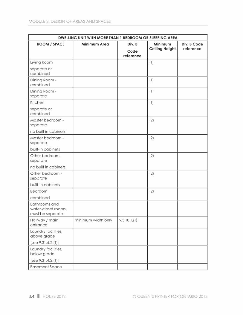
MODULE 3 DESIGN OF AREAS AND SPACES
DWELLING UNIT WITH MORE THAN 1 BEDROOM OR SLEEPING AREAROOM / SPACE Minimum Area Div. B
Code reference
Minimum Ceiling Height
Div. B Code reference
Living Room
separate or combined
(1)
Dining Room - combined
(1)
Dining Room - separate
(1)
Kitchen
separate or combined
(1)
Master bedroom - separate
no built in cabinets
(2)
Master bedroom - separate
built-in cabinets
(2)
Other bedroom - separate
no built in cabinets
(2)
Other bedroom - separate
built-in cabinets
(2)
Bedroom
combined
(2)
Bathrooms and water-closet rooms must be separateHallway / main entrance
minimum width only 9.5.10.1.(1)
Laundry facilities, above grade
[see 9.31.4.2.(1)]Laundry facilities, below grade
[see 9.31.4.2.(1)]Basement Space
4.6 HOUSE 2012 © QUEEN’S PRINTER FOR ONTARIO 2013
MODULE 4 DOORS
EXTERIOR DOORSPart 12, “Resource Conservation” applies to Houses. [Division A, Sentence 1.1.2.1.(1)]
For a permit that is applied for after before January 1, 2017 the energy efficiency provisions of a House intended for occupancy on a continuing basis during the winter months must:
□ meet the performance level that is equal to a rating of 80 or more when evaluated in accordance with NRCan, “EnerGuide for new Houses: Administrative and Technical Procedures” [Sentence 12.2.1.1.(1) and Clause 12.2.1.1.(3)(a)]
or
□ conform to Chapters 1 and 2 of MMAH Supplementary Standard SB-12. [Sentence 12.2.1.1.(1) and Clause 12.2.1.1.(3)(b)]
In the House - 2012 course, we will not deal with the evaluation in accordance with NRCan, “EnerGuide for new Houses: Administrative and Technical Procedures”. However, a House with a label indicating a rating of 80 or more demonstrates that the requirement of Clause 12.2.1.1.(3)(a) has been complied with.
All references to NRCan, “EnerGuide for New Houses: Administrative and Technical Procedures” are to the 2005 edition with all amendments, revisions and supplements effective to May 31, 2006. [SB-12 Sentence 1.4.1.1.(2)]
As with any other Division B provision, the plans are reviewed by the Plans Examiner and the construction is verified by the Building Inspector. When a Registered Code Agency (RCA) is involved, the RCA or Persons authorized by the RCA would perform the plans examination and inspection activities.
The provisions of SB-12 will be dealt with systematically as we proceed through the remainder of this course.
© QUEEN’S PRINTER FOR ONTARIO 2013 HOUSE 2012 4.11
MODULE 4 DOORS
4
Where an exterior air barrier is penetrated by an exterior door, the air barrier system must be sealed to the door frame with:
□ compatible flexible flashing material, [Clause 9.25.3.3.(12)(a)]
or
□ caulking, [Clause 9.25.3.3.(12)(b)]
or
□ spray foam insulation. [Clause 9.25.3.3.(12)(c)]
EXERCISE # 3 - CONTINUITY OF AIR BARRIER SYSTEM
1. True or false? Where an air barrier system is penetrated by an exterior door, such air barrier system must be sealed to maintain the integrity of the air barrier system.
a) True
b) False
Code reference:
2. When an exterior air barrier system is penetrated by an exterior door, such air barrier system could be sealed to the door frame with:
a) caulking
b) compatible tape
c) flashing material that conforms to Article 9.27.3.7.
d) air barrier material that is lapped not less than 100 mm and clamped
Code reference:
STOP

© QUEEN’S PRINTER FOR ONTARIO 2013 HOUSE 2012 5.21
MODULE 5 WINDOWS, DOORS AND SKYLIGHTS
5
METHODS OF ACHIEVING ENERGY EFFICIENCY COMPLIANCE UNDER PART 12 AND SB-12
WINDOWS AND RESOURCE CONSERVATION PROVISIONSPart 12 regulates the mandatory and enabling energy efficiency requirements of Houses.
For a permit that is applied for before January 1, 2017 the energy efficiency provisions of a House intended for occupancy on a continuing basis during the winter months must:
□ meet the performance level that is equal to a rating of 80 or more when evaluated in accordance with NRCan, “EnerGuide for new Houses: Administrative and Technical Procedures” [Sentence 12.2.1.1.(1) and Clause 12.2.1.1.(3)(a)]
or
□ conform to Chapters 1 and 2 of Supplementary Standard SB-12. [Sentence 12.2.1.1.(1) and Clause 12.2.1.1.(3)(b)]
Compliance with Chapters 2 and 3 of SB-12 is deemed to meet the energy efficiency requirements in accordance with Sentence 12.2.1.1.(3) [SB-12, Sentence 1.1.1.2.(1)]
In the House - 2012 course, we will not deal with the evaluation in accordance with NRCan, “EnerGuide for new Houses: Administrative and Technical Procedures”. However, a House with a label indicating a rating of 80 or more demonstrates that the requirement of Clause 12.2.1.1.(3)(a) has been complied with.
All references to NRCan, “EnerGuide for New Houses: Administrative and Technical Procedures” are to the 2005 edition with all amendments, revisions and supplements effective to May 31, 2006. [SB-12 Sentence 1.4.1.1.(2)]
5.24 HOUSE 2012 © QUEEN’S PRINTER FOR ONTARIO 2013
MODULE 5 WINDOWS, DOORS AND SKYLIGHTS
3. If the House in Question # 2 had an electric forced-air furnace, its windows would require a thermal conductance, U-value of:
a) not more than 2.0 W/m²∙K
b) not less than 35 as an energy rating for operable windows
c) not more than 1.6 W/m²∙K
d) not less than 1.6 W/m²∙K
SB-12 references:
4. The MITEC House has a natural gas forced-air furnace with a 90% annual fuel utilization efficiency. If it was constructed in Ottawa, its windows would require a thermal conductance, U-value of:
a) not more than 1.6 W/m²∙K
b) not less than 1.6 W/m²∙K
c) not more than 25 as an energy rating for operable windows
d) not less than 25 as an energy rating for fixed windows
SB-12 references:
5. If the House in Question # 4 had an electric forced-air furnace, its windows would require a thermal conductance, U-value of:
a) not more than 2.0 W/m²∙K
b) not less than 35 as an energy rating for operable windows
c) not more than 1.6 W/m²∙K
d) not less than 1.6 W/m²∙K
SB-12 references:
6. The windows of the MITEC House in question # 4 (Ottawa without an HRV) could have a thermal conductance of 1.8 W/m²∙K, as determined from CAN/CSA-A440.2, “Fenestration Energy Performance”, when the natural gas forced-air heating system has an annual fuel utilization efficiency of:
a) not less than 90%
b) not more than 90%
c) not less than 94%
d) not more than 94%
SB-12 reference:

5.26 HOUSE 2012 © QUEEN’S PRINTER FOR ONTARIO 2013
MODULE 5 WINDOWS, DOORS AND SKYLIGHTS
11. Under all circumstances and anywhere in Ontario, the skylight of the MITEC House would require a thermal conductance, U-value of:
a) not more than 2.8 W/m²∙K
b) not less than 2.6 W/m²∙K
c) not more than 17 as an energy rating for operable skylights
d) not less than 27 as an energy rating for fixed skylights
SB-12 references:
STOP
CONTRIBUTION OF ENCLOSED UNHEATED SPACEWhere an enclosed unheated space such as a porch, verandah or vestibule is separated from a heated space by glazing, the unheated enclosure may be considered to provide thermal resistance of RSI 0.16. [SB-12, Sentence 2.1.1.1.(15)]
AREA OF WINDOWS AND GLAZING V. GROSS AREA OF EXTERIOR WALLSAs a general rule, where the gross area of windows, sidelights, skylights, glazing in doors and sliding glass doors to the gross area of peripheral walls (the sum of the area of all exterior walls) measured from grade to the top of the upper most ceiling is not more than 17%, the House must comply with a compliance package selected from Tables 2.1.1.2.A, 2.1.1.2.B, and 2.1.1.2.C, and Tables 2.1.1.3.A, 2.1.1.3.B and 2.1.1.3.C. [SB-12, Sentence 2.1.1.1.(7)]

© QUEEN’S PRINTER FOR ONTARIO 2013 HOUSE 2012 5.31
MODULE 5 WINDOWS, DOORS AND SKYLIGHTS
5
2. The two-storey House depicted on drawing M5:2 will be constructed in Timmins. The natural gas furnace has an annual fuel utilization efficiency of 94% and the designer has selected Compliance Package D.
TIMMINS HOUSE DOOR - WINDOW SCHEDULEOpening
number
Opening Type Dimensions in metres
1 Sliding glass door 2 × 22 Window 1.75 × 1.53 Window 1.75 × 1.54 Window 3 × 1.55 Insulated steel door 1 × 26 Window 3 × 1.57 Window 3 × 1.58 Window 1 × 1
9 Window 2.5 × 1.5
a) What is the ratio of the gross area of windows (glazing) to gross area of peripheral walls?

© QUEEN’S PRINTER FOR ONTARIO 2013 HOUSE 2012 5.33
MODULE 5 WINDOWS, DOORS AND SKYLIGHTS
5
b) What is the required overall coefficient of heat transfer for the windows and sliding glass door for the two-storey House?
AIR INFILTRATION AND THE CONTINUITY OF THE AIR BARRIER SYSTEM AT WINDOWSPenetration of the air barrier system by a must be sealed to maintain the integrity of the air barrier system. [Sentence 9.25.3.3.(10)]
Where an interior air barrier is penetrated by a window or other fenestration, the air barrier system must be sealed to the window frame with:
□ compatible tape, [Clause 9.25.3.3.(11)(a)]
or
□ spray foam insulation. [Clause 9.25.3.3.(11)(b)]
Where an exterior air barrier is penetrated by a window or other fenestration, the air barrier system must be sealed to the window frame with:
□ compatible flexible flashing material, [Clause 9.25.3.3.(12)(a)]
or
□ caulking, [Clause 9.25.3.3.(12)(b)]
or
□ spray foam insulation. [Clause 9.25.3.3.(12)(c)]
© QUEEN’S PRINTER FOR ONTARIO 2013 HOUSE 2012 6.25
MODULE 6 STAIRS, RAMPS, HANDRAILS AND GUARDS
6
OPENINGS IN GUARDSIn Houses, openings through a guard, required by Article 9.8.8.1., must be of a size that will prevent the passage of a spherical object having a diameter of 100 mm unless it can be shown that the location and size of openings that exceed the 100 mm limit do not represent a hazard. [Sentences 9.8.8.5.(1) and A-9.8.8.5.(1)]
In Houses, unless it can be shown that the location and size of openings through guards do not represent a hazard, openings through a guard, that is not required by Article 9.8.8.1., must be of a size that will:
□ preventthepassageofasphericalobjecthavingadiameterof100mm, [Clause 9.8.8.5.(3)(a)]
or
□ permitthepassageofasphericalobjecthavingadiameterof200mm. [Clause 9.8.8.5.(3)(b)]
HEIGHT OF WINDOW SILLS ABOVE FLOORS / GROUNDThe primary intent of Sentence 9.8.8.1.(5) is to minimize the likelihood that, as a result of the design or construction of a building, small children will be exposed to an unacceptable risk of injury due to hazards caused by falling from openable windows.
The requirement applies only to buildings of residential occupancy and generally located on the secondfloororhigherofadwellingunitthatislocatedaboveanothersuiteofanyoccupancywhere the windows are essentially free-swinging or free-sliding.
Free swinging or free-sliding means that once a window that has been cracked open it can be opened further by simply pushing on it.
The 100 mm opening limit is consistent with openings in guards provisions under Article 9.8.8.5. It is only invoked when the other dimension of the opening is more than 380 mm. The 480 mm height offthefloorrecognizesthatfurnitureisoftenplacedunderwindowsandsmallchildrenareoftengood climbers. Let’s paraphrase the provisions of Article 9.7.1.6.
As a general rule, openable windows in buildings of residential occupancy must be protected by:□ aguardconformingtoSubsection9.8.8.

6.26 HOUSE 2012 © QUEEN’S PRINTER FOR ONTARIO 2013
MODULE 6 STAIRS, RAMPS, HANDRAILS AND GUARDS
• 9.8.8.2., “Loads on Guards”,
• 9.8.8.3., “Height of Guards”,
• 9.8.8.5., “Openings in Guards”,
• 9.8.8.6., “Design to Prevent Climbing”, and
• 9.8.8.7., “Glass in Guards”, [Clause 9.8.8.1.(5)(a)]
or
□ amechanismcapableofcontrollingthefreeswingingorslidingoftheopenablepartof the window so as to limit any clear unobstructed opening to not more than 100 mm measured either vertically or horizontally where the other dimension is greater than 380 mm. [Clause 9.8.8.1.(5)(b)]
As an exception to the general rule, openable windows serving Houses need not be protected by a guard or a mechanism controlling the size of the opening when:
□ adwellingunitisnotlocatedaboveanotherdwellingunitintheHouse, [Clause 9.8.8.1.(6)(a)]
As further exceptions to the general rule, when a dwelling unit is located above another dwelling unit in a House, an openable window in either dwelling unit need not be protected by a guard or a mechanism controlling the size of the opening where:
□ theonlyopeninggreaterthan100mmby380mmisahorizontalopeningatthetopofthe window, [Clause 9.8.8.1.(6)(b)]
or
□ thetopsurfaceofthesilloftheopenablewindowislocatedmorethan480mmabovethefinishedfloorononesideoftheopenablewindow, [Clause 9.8.8.1.(6)(c)]
or

© QUEEN’S PRINTER FOR ONTARIO 2013 HOUSE 2012 6.27
MODULE 6 STAIRS, RAMPS, HANDRAILS AND GUARDS
6
□ thedifferenceinelevationbetweenthefinishedfloorintheroomorspacewiththeopenablewindowandafloororthegroundontheothersideoftheopenablewindowisless than 1 800 mm. [Clause 9.8.8.1.(6)(d)]
DESIGN TO PREVENT THE CLIMBING OF A GUARDUnless it can be shown that the location and size of openings through guards do not represent a hazard, guards required by Article 9.8.8.1., must be designed so that no member, attachment or opening will facilitate climbing. [Sentence 9.8.8.6.(1)]
GLASS IN GUARDSGlass in guards must be:
□ safetyglassofthelaminatedortemperedtypeconformingtoCAN/CGSB-12.1-M,“Tempered or Laminated Safety Glass”, [Clause 9.8.8.7.(1)(a)]
or
□ wiredglassconformingtoCAN/CGSB-12.11-M,“WiredSafetyGlass”. [Clause 9.8.8.7.(1)(a)]
EXERCISE # 1 - MINIMUM DIMENSIONS OF THE COMPONENT PARTS OF STAIRS AND CLEARANCES IN STAIRCASE
1. Examine Drawings M6:1 INTERIOR STAIR DETAIL and M6:2 HANDRAIL STAIR DETAIL and complete the Table by writing in the required dimension and the corresponding Code reference. In addition to what you already reviewed, you will need to Consult Subsection 9.8.9., “Construction”.

© QUEEN’S PRINTER FOR ONTARIO 2013 HOUSE 2012 7.29
MODULE 7 MEANS OF EGRESS
7
OBSTRUCTIONS IN A PUBLIC CORRIDOR OR SHARED EXIT PASSAGEWAY IN A HOUSE WITH TWO DWELLING UNITS
21. As a general rule, in a House with two dwelling units, obstructions located 1 980 mm or less above the floor must not project horizontally more than 100 mm into a public corridor or shared exit passageway in a manner that would create a hazard for persons with low or no vision travelling adjacent to walls. [Sentence 9.9.5.3.(1)]
a) As an exception to the general rule, the horizontal projection is permitted to exceed 100 mm where the horizontal projection extends to less than 680 mm above the floor. [Sentence 9.9.5.3.(2)]
b) The requirements of Article 9.9.5.3., “Obstructions in Public Corridors and shared exit passageways are illustrated in Drawing M7:3 on the next page.
M7:3 - CONTROL OF OBSTRUCTIONS FOR PERSONS WITH NO OR LOW VISION IN PUBLIC CORRIDORS AND SHARED EXIT PASSAGEWAYS, ARTICLE 9.9.5.3.

© QUEEN’S PRINTER FOR ONTARIO 2013 HOUSE 2012 7.53
MODULE 7 MEANS OF EGRESS
7
47.(a) In a House with two dwelling units, the minimum value of the illumination required by Sentence 9.9.12.2.(2) shall be not less than 10 lx.
EMERGENCY LIGHTING IN A SHARED EGRESS FACILITY IN A HOUSE WITH TWO DWELLING UNITS
48. In a House with two dwelling units, emergency lighting must be provided in:
□ shared exits, [Clause 9.9.12.3.(1)(a)]
and
□ shared underground walkways, [Clause 9.9.12.3.(1)(d)]
and
□ public corridors. [Clause 9.9.12.3.(1)(e)]
48.(a) In a House with two dwelling units, required emergency lighting must be powered by an emergency power supply (e.g., batteries, generators, power inverters etc.) that is separate from the electrical supply provided for the building. [Sentence 9.9.12.3.(2)]
48.(b) In a House with two dwelling units, required emergency lighting must be designed:□ to power up automatically when the regular electric lighting in the affected area is
interrupted,
and
8.70 HOUSE 2012 © QUEEN’S PRINTER FOR ONTARIO 2013
MODULE 8 FIRE PROTECTION
9. When the minimum required LD is doubled under the provisions of Sentence 9.10.14.3.(1), the aggregate area of UO:
a) cannot be increased from what was originally calculated under Sentence 9.10.14.4.(1) and Table 9.10.14.4.
b) can be increased provided the LD is not irregular or skewed
c) the LD need not be doubled when the UO are glazed with wired glass in fixed steel frames conforming to Article 9.10.13.5. or glass block conforming to Article 9.10.13.7.
d) the building must be sprinklered
STOP
63. SPATIAL SEPARATIONS BETWEEN HOUSES UNDER SUBSECTION 9.10.15.The provisions of Subsection 9.10.15., “Spatial Separations Between Houses”, apply to Houses where:
□ a dwelling unit is not located above another dwelling unit, [Clause 9.10.15.1.(1)(a)]
and
□ the spatial separation is not designed under Subsection 9.10.14. [Clause 9.10.15.1.(1)(b)]
64. AREA AND LOCATION OF EBF UNDER 9.10.15.a) The area of an EBF must be:
□ taken as the exterior wall area facing one direction on any side of a building, [Clause 9.10.15.2.(1)(a)]
and calculated as
□ the total area measured from the finished ground level to the uppermost ceiling, [Subclause 9.10.15.2.(1)(b)(i)]
or
□ the area of each fire compartment where the building is divided into fire compartments by fire separations with a fire-resistance rating not less than 45 minutes, [Suclause 9.10.15.2.(1)(b)(ii)]
or

© QUEEN’S PRINTER FOR ONTARIO 2013 HOUSE 2012 8.73
MODULE 8 FIRE PROTECTION
1
or
b) an opening of not more than 130 cm2 in an EBF is not considered as an UO. [Sentence 9.10.15.3.(1) → 9.10.15.4.(5)]
or
c) exposed heavy timber and steel columns in an EBF need not comply with Sentence 9.10.15.5.(1) when the LD is not less than 6 m [doubled from 3 m]. [Sentence 9.10.15.3.(1) → 9.10.15.5.(6)]
66. GLAZED OPENINGS IN EBF UNDER 9.10.15.a) As a general rule, the maximum area of GO in an EBF must:
□ conform to Table 9.10.15.4., “Maximum Area of Glazed Openings in Exterior Walls of Buildings Containing Only Dwelling Units”, [Clause 9.10.15.4.(1)(a)]
or
□ conform to Subsection 3.2.3., as if the glazed openings were unprotected openings, [Clause 9.10.15.4.(1)(b)]
or
□ where the limiting distance is not less than 1.2m, be equal to or less than LD2. [Clause 9.10.15.4.(1)(c)]
b) As an exceptions to the general rule:
i) □ the limits on area of GO do not apply to an EBF of a dwelling unit facing a detached garage or detached accessory building provided that:
□ the detached garage or detached accessory building serves only one dwelling unit, [Clause 9.10.15.4.(3)(a)]
and
□ the detached garage or detached accessory building is located on the same property as the dwelling unit it serves, [Clause 9.10.15.4.(3)(b)]

8.82 HOUSE 2012 © QUEEN’S PRINTER FOR ONTARIO 2013
MODULE 8 FIRE PROTECTION
10. Consider staggered townhouse units where the limiting distance is 0. The Designer wants to make use of vinyl siding. In your own words, describe the installation.
When vinyl siding is used as cladding in the EBF of a house with a limiting distance of less than 600 mm, the requirements of Clause 9.10.15.5.(2)(c) for noncombustible cladding may be satisfied with the installation of vinyl siding:
References:
STOP
68. FIRE BLOCKSFire blocks are elements of building assemblies that are installed at strategic locations to resist the passage of flames from one concealed space to another. While the term is not defined it is associated with the principle of compartmentation to prevent fire spread.
Thus, we can conclude that a fire block is: draft-tight barrier within or between construction assemblies that acts to retard the passage of smoke and flame.
Another purpose of fire blocks is to limit the size of concealed spaces such as stud cavities, crawl spaces, attic and ceiling spaces and spaces between the framing and the exterior building envelope by creating draft-tight compartments.
A review of Article 9.10.16.1. reveals that the requirement of a fire stop can be associated with the flame-spread rating of the exposed construction material within the concealed space. Before we deal with the determination of flame-spread rating, you should know that Table 3.1.1.A. of SB-2 indicates that lumber and most panel type boards have a generic flame-spread rating of 150.
The requirements of Subsection 9.10.16., “Fire Blocks” have been paraphrased. In the space provided note any comment, question or concern.
69. REQUIRED FIRE BLOCKS IN CONCEALED SPACESa) Concealed spaces in interior walls must be separated by fire blocks from concealed
spaces in:
□ exterior walls,

© QUEEN’S PRINTER FOR ONTARIO 2013 HOUSE 2012 8.87
MODULE 8 FIRE PROTECTION
1
and
□ extends from below the bottom of the top plates in the lower storey to above the top of the bottom plate in the upper storey, [Clause 9.10.16.3.(3)(c)]
and
□ completely fills the nominal gap of 25 mm between the headers and between the wall plates. [Clause 9.10.16.3.(3)(d)]
72. PENETRATION OF FIRE BLOCKSWhere fire blocks are pierced by pipes, ducts or other elements, the effectiveness of the fire stops must be maintained around such elements. [Sentence 9.10.16.4.(1)]
EXERCISE # 10 - FIRE BLOCKS FOR HOUSESConsult Subsection 9.10.16., “Fire Blocks”. Standard procedures apply. As always, provide references when prompted.
1. Make a list of fire block materials that can be used in the construction of Houses.
Required fire stops in Houses of combustible construction must be constructed of not less than:a)
b)
c)
d)
e)
References:
8.88 HOUSE 2012 © QUEEN’S PRINTER FOR ONTARIO 2013
MODULE 8 FIRE PROTECTION
2. Sentence 9.10.16.4.(1) of Division B informs us that where fire blocks are pierced by pipes, ducts or other elements, the effectiveness of the fire stops are to be maintained around such elements. In your opinion, how is the integrity of the fire stop maintained around such elements in Houses of combustible construction?
Where fire blocks are pierced by pipes, ducts or other elements in Houses of combustible construction, the effectiveness of the fire stop shall be maintained around such elements by:
STOP
73. FLAME SPREAD LIMITSTHE NATURE OF FLAME-SPREAD RATINGDuring a fire, flames will spread along the exposed surfaces of different construction materials and interior finishes at different rates.
A flame-spread rating is determined by laboratory tests that calculate the rate at which flame travels along the test specimen, or the maximum distance that a controlled flame travels in a given period of time. The rating system is complex. Essentially, the results of the test compare the rate of flame travel along the surface of the material being tested against two standard materials which were both assigned an arbitrary benchmark flame-spread rating.
□ untreated red oak is rated at 100
and
□ asbestos cement board is rated at 0
According to Clause 1.4.1.2.(1)(c) of Division A, flame-spread rating is:an index or classification indicating the extent of the spread of flame on the surface of a material or an assembly of materials as determined in a standard fir test as described in the Code.
Flame-spread rating is used to control the use of construction materials as interior finishes. In the next exercise we will determine the permitted flame-spread limits of interior surfaces of Houses and the use of Supplementary Standard SB-2, “Fire Performance Ratings” to verify the generic flame-spread rating of common construction materials.
To obtain information about listed flame-spread rating of construction materials, consult ULC’s List of Equipment and Materials, Building Materials under Guide 40 U8, “Classification of Materials as to Surface Burning Characteristics”.

© QUEEN’S PRINTER FOR ONTARIO 2013 HOUSE 2012 8.89
MODULE 8 FIRE PROTECTION
1
Underwriters Laboratories Inc. and Intertek, the latter making use of the Warnock Hersey trademark, are also accredited by the Standards Council of Canada to list the flame-spread rating of materials, assemblies of materials and structural members for use in the construction of buildings in Ontario.
74. FLAME-SPREAD RATING OF INTERIOR SURFACES OF HOUSESThe requirements of Subsection 9.10.17., “Flame Spread Limits” have been paraphrased. In the space provided note any comment, question or concern.
a) As a general rule, the exposed surface of every interior wall and ceiling of a House, including skylights and glazing must have a flame-spread rating (FSR) of not more than 150. [Sentence 9.10.17.1.(1)]
b) As exceptions to the general rule:
i) □ doors in Houses must have a FSR of not more than 200, [Sentence 9.10.17.1.(2)]
ii) □ doors within dwelling units, other than vehicle garage doors, do not require a
flame-spread rating, [Sentence 9.10.17.1.(3)]
iii) □ vehicle (storage) garage door must have a surface FSR of not more than 200
[Sentence 9.10.17.1.(3) → 9.10.17.1.(2)]
and when they are factory-assembled and incorporate foamed plastic insulation
□ the foamed plastic insulation may have a cross-sectional FSR of not more than 500, [Sentence 9.10.17.10.(2)]
and
□ the foamed plastic insulation must be covered on the interior with a metallic foil, [Clause 9.10.17.10.(2)(a)]
□ the assembly (vehicle garage door) has a surface FSR of not more than 200, [Clause 9.10.17.10.(2)(b)]
8.104 HOUSE 2012 © QUEEN’S PRINTER FOR ONTARIO 2013
MODULE 8 FIRE PROTECTION
91. SILENCING OF SMOKE ALARM’S ALARM SIGNALA manually operated device is permitted to be incorporated within the circuitry of a smoke alarm installed in a dwelling unit so that it will silence the signal emitted by the smoke alarm for a period of not more than 10 minutes, after which the smoke alarm will reset and again sound the alarm if the level of smoke in the vicinity is sufficient to reactuate the smoke alarm. [Sentence 9.10.19.6.(1)]
EXERCISE # 13 - INSTALLATION OF SMOKE ALARMS IN DWELLING UNITSConsult Subsection 9.10.19., “Smoke Alarms”, follow the established procedure and deal with the questions that follow.
1. Consider Clause Article 9.10.19.3. Within the MITEC House there must be at least:
a) 1 smoke alarm
b) 5 smoke alarms
c) 6 smoke alarms
d) 3 smoke alarms
Reference:
2. Explain the rational for your choice of answer in question 1.
References:
3. Under which circumstance would the Code require a smoke alarm to be installed inside the bedrooms on the second floor level of the MITEC House?
Reference:

© QUEEN’S PRINTER FOR ONTARIO 2013 HOUSE 2012 8.105
MODULE 8 FIRE PROTECTION
1
4. When a smoke alarm is located outside a bedroom, the smoke alarm on such bedroom floor level must be within:
a) 900 mm of the bedroom door measured following corridors and doorways
b) in a location between the sleeping room and the remainder of the storey
c) 15 m of the bedroom door measured following corridors and doorways
d) in a dwelling unit the smoke alarm is not permitted to be located outside a bedroom.
Reference:
5. A required smoke alarm in a dwelling unit must be installed:
a) at or near the ceiling
b) at or near the ceiling and in accordance with the manufacturer’s instructions
c) in accordance with UL 2034,
d) on any floor level provided it is audible within the bedrooms when the intervening doors are closed.
References:
6. As a general rule, Sentence 9.10.19.4.(1) requires smoke alarms in dwelling units to be installed by permanent connections to an electrical circuit and disconnect switches are not permitted between the overcurrent circuit device and the smoke alarm. Under which circumstances can smoke alarms in Houses be battery operated?
References:
7. Consider the MITEC House in Question № 1. Describe the interconnection requirement for each of the six required smoke alarms.
Reference:

8.120 HOUSE 2012 © QUEEN’S PRINTER FOR ONTARIO 2013
MODULE 8 FIRE PROTECTION
b) Contribution of light steel frame
SB-2 reference: c) Contribution of insulation
Rock fibre insulation in steel stud wall =
SB-2 reference:
d) Fire-resistance rating of assembly =
STOP
108. CONSIDERATIONS FOR VARIOU TYPES OF ASSEMBLIES UNDER SB-2Subsections 2.3.5. to 2.3.14. of SB-2 provide guidance on using the generic method to determine the fire-resistance rating of wood and steel framed wall, floor and roof assemblies. The guidance provided is summarized in the Table on page 114. In the space provided, note ay comment, concern or question.

10.16 HOUSE 2012 © QUEEN’S PRINTER FOR ONTARIO 2013
MODULE 10 EXCAVATION
EXERCISE # 6 - ANGLE OF REPOSE OF SOILSAccording to Sentence 1.2.1.1.(1), of division C, where the foundations of a building are to be constructed below the level of the footings of an adjacent building and within the angle of repose of the soil, as drawn from the bottom of the footings, the foundations must be designed by a suitably qualified and experienced person.
The angle of repose is the steepest angle at which a pile of unconsolidated grains of soil (see definition of fine and coarse grained soils) will remain stable.
The angle of repose is determined by the frictional contact between the grains of soil. In general, for dry soils the angle of repose increases with increasing grain size and usually lies between 30° and 37° to the horizontal.
Slightly wet unconsolidated soils tend to exhibit a very high angle of repose because surface tension between the water and grains of soil tends to hold the grains in place.
In saturated soils the angle of repose is reduced to very small values and the soils tend to flow like a fluid.
If we were to deposit sand or gravel by pouring it from a single point above the ground, it would form a conical pile. As more and more granular material was deposited on the pile, the slope for a short period of time might appear to be steep, but eventually the soil particles would slip and slide down the slope.
© QUEEN’S PRINTER FOR ONTARIO 2013 HOUSE 2012 11.7
MODULE 11 DAMPPROOFINg, WATERPROOFINg AND SOIL gAS CONTROL
1
□ nomembraneorcoatingwithapermeancelessthan170ng/(Pa.s.m2)mustbeappliedtotheinteriorsurfaceofthefoundationwallabovegroundlevelbetweentheinsulationandthefoundationwall. [Clause9.13.2.6.(2)(b)]
c) Whereinsulationfunctionsasbothmoistureprotectionforinteriorfinishesandasa
vapourbarrierinaccordancewithSubsection9.25.4.itmustbeappliedovertheentireinteriorsurfaceofthefoundationwall. [Sentence9.13.2.6.(3)]
9. PERMEANCE OF CONSTRUCTION MATERIALSPermeanceistherateofwatervapourtransmissionperunitareaatasteadyratethroughamaterial.Justlikefire-resistanceratingandflame-spreadratingwhicharedeterminedbytestinalaboratory,permeanceisdeterminedinaccordancewithASTME96/E96M,“WaterVapourTransmissionofMaterials”.
PermeanceisthenumberthatisusedtocomparevariousconstructionmaterialsinregardtomoisturetransmissionresistanceandisdependantonthicknessmuchliketheRSI-valueofthermalinsulation.Watervapourrateofpermeance,forselectedconstructionmaterials,areshowninTableA-9.25.5.1.(1),“AirandVapourPermeanceValues”.SeeVolume2oftheBuildingCodeCompendium.
10. DAMPPROOFING OF FLOORS-ON-GROUNDa) Asageneralrule,whenfloors-on-groundaredampproofed,thedampproofingmustbe
installedbelowthefloor. [Sentence9.13.2.7.(1)]

© QUEEN’S PRINTER FOR ONTARIO 2013 HOUSE 2012 11.21
MODULE 11 DAMPPROOFINg, WATERPROOFINg AND SOIL gAS CONTROL
1
4. Inyourownwords,describethetestingstandardfortheevaluationofasubfloordepressurizationsystem,todeterminetheradonconcentrationinthebuilding,includingthebasement.
InaHousecontainingonlyonedwellingunit,todeterminetheradonconcentration,includingthebasementconcentrationmeasurements,asubfloordepressurizationsystem,mustbetestedaccordingto:
SB-9references:
5. AcopyoftheresultsoftestingrequiredunderSentences3.2.(6)and(8)ofSupplementaryStandardSB-9,“RequirementsforSoilGasControl”mustbeforwardedtothe:
a) RegisteredCodeAgency
b) ChiefBuildingOfficial
c) ChiefBuildingOfficialortheInspectorwhohasthesamepowersanddutiesasthechiefbuildingofficialinrelationtoplumbing,asthecasemaybe
d) theChiefBuildingOfficialortheRegisteredCodeAgencyhavingjurisdiction
SB-9reference:
6. Completethefollowingstatement.Whentestingdeterminesthatradonconcentrationexceeds200Bq/m³inthenormaloccupancyarea:
SB-9reference:
7. Completethefollowingstatement.Whenasubfloordepressurizationsystemisinstalledmakeupairmustbeprovidedinaccordancewith:
SB-9references:
STOP

© QUEEN’S PRINTER FOR ONTARIO 2013 HOUSE 2012 12.9
MODULE 12 DRAINAgE
1
10. DISPOSAL OF DRAINAGE FROM DRAIN TILE, DRAIN PIPE OR (HORIZONTAL) GRANULAR DRAINAGE LAYER BY A PUMP IN A SUMP PIT
a) Where gravity drainage is not practical, drainage from drain tile, drain pipe or (horizontal) granular drainage layer at the bottom of a foundation must discharge into a covered sump pit equipped with an automatic pump that will discharge the drainage water into a sewer, drainage ditch or dry well. [Sentence 9.14.5.2.(1)]
b) The cover of the sump pit must be designed to resist removal by children. [Sentence 9.14.5.2.(2)]
c) Sealed in accordance with Sentence 9.25.3.3.(16)
11. DRY WELL FOR THE DISPOSAL OF DRAINAGE FROM DRAIN TILE, DRAIN PIPE OR (HORIZONTAL) GRANULAR DRAINAGE LAYERWhen drainage from drain tile, drain pipe or a (horizontal) granular drainage layer is drained by gravity or by way of an automatic pump in a sump pit into a dry well, the dry well must be located:
□ inanareawherethenaturalgroundwaterlevelisbelowthebottomofthedrywell, [Sentence 9.14.5.3.(1)]
and
□ notlessthan5mfromthefoundationwherethedrainagecomesfrom,
and
□ sothatthebottomofthedrywelldrainsawayfromthebuilding. [Sentence 9.14.5.3.(2)]
12. SURFACE DRAINAGEThe building must be so located and the building site so graded so that surface water:
□ willnotaccumulateatornearthebuildingafteranybackfillhassettled, [Sentences 9.14.6.1.(1) and 9.12.3.2.(1)]
and

12.10 HOUSE 2012 © QUEEN’S PRINTER FOR ONTARIO 2013
MODULE 12 DRAINAgE
□ willnotadverselyaffectadjacentproperties. [Sentence 9.14.6.1.(1)]
13. SURFACE DRAINAGE AWAY FROM WELLS (WATER SUPPLY) AND SEWAGE SYSTEMSSurface drainage must be directed away from the location of:
□ awatersupplywell,
or
□ sewagesystem(leachingbed). [Sentence 9.14.6.2.(1)]
14. DRAINAGE OF SURFACE WATER IN WINDOW WELLSEvery window well must be drained to the footing level or other suitable location such as a sewer, drainage ditch or dry well. [Sentence 9.14.6.3.(1)]
15. SURFACE DRAINAGE BY CATCH BASIN IN A DRIVEWAYWheresurfacedrainagewaterfromadrivewayislikelytoaccumulateinfrontoftheoverheadgarage doors or enter in the garage, a catch basin must be installed to remove the surface drainage water. [Sentence 9.14.6.4.(1)]

© QUEEN’S PRINTER FOR ONTARIO 2013 HOUSE 2012 13.25
MODULE 13 FOOTINGS AND FOUNDATIONS
1
EXERCISE # 3 - FOOTINGSStandard procedures apply. Consider Subsection 9.15.3., “Footings” and deal with the questions that follow and provide references when prompted to do so.
1. The minimum footing sizes of Table 9.15.3.4. are based on a maximum specified live load, on any floor supported by the footings, of:
a) 1.4kPa
b) 1.9 kPa
c) 2.4 kPa
d) 3.6 kPa
Reference:
2. According to Table 4.1.5.3., by way of Clauses 9.4.1.1.(1)(c), 9.23.4.1.(1)(a) and (b), the minimum specified uniformly distributed live load on any area of floor other than floors of bedrooms in Houses is:
a) 1.4kPa
b) 1.9 kPa
c) 2.4 kPa
d) 3.6 kPa
Reference:
3. According to Table 4.1.5.3., by way of Clauses 9.4.1.1.(1)(c), 9.23.4.1.(1)(a) and (b), the minimum specified uniformly distributed live load on floors of bedrooms in Houses is:
a) 1.4 kPa
b) 1.9 kPa
c) 2.4 kPa
d) 3.6 kPa
Reference:
4. Consider a one-storey detached House with vinyl siding and engineered wood joists that span 7.32 m on each side of a centre beam supported by columns. The footings supporting exterior walls will need to be a minimum width of:
a) 250 mm
b) 350 mm
c) 375 mm
d) 400 mm
References:

13.26 HOUSE 2012 © QUEEN’S PRINTER FOR ONTARIO 2013
MODULE 13 FOOTINGS AND FOUNDATIONS
5. Consider a two-storey detached House with brick veneer on both storeys and engineered wood joists that span 7.32 m on both sides of a basement beam and the floor joists of the second storey span 6 m from bearing partitions on the first floor. The footings supporting exterior walls will need to be a minimum width of:
a) 480 mm
b) 655 mm
c) 960 mm
d) 1440 mm
References:
6. For the one-storey detached House in Question № 4 the footing area for columns spaced 3 m o.c. will need a minimum of:
a) 0.4 m2
b) 0.75 m2
c) 0.6 m2
d) 0.9 m2
References:
7. Consider the MITEC House and calculate the minimum width of the strip footing supporting the exterior foundation wall.
a) 250 mm
b) 350 mm
c) 380 mm
d) 480 mm
References:
8. How does the required footing width in Question № 7 compare with what is proposed by Wall Section B?

© QUEEN’S PRINTER FOR ONTARIO 2013 HOUSE 2012 13.27
MODULE 13 FOOTINGS AND FOUNDATIONS
1
9. Consult the Basement Plan of the MITEC House. The area of floor being supported by the column that is closest to the furnace was calculated as 9 m2. Evaluate the appropriateness of the area of the footing supporting the said column.
In Question № 7, we calculated the minimum width of the strip footing supporting the exterior walls of the MITEC House, at 480 mm. Consult Wall Section B. If the MITEC House was to be constructed on gravel, sand or silt where the elevation of the water table was 450 mm below the underside of footing elevation, the width of the footing supporting the exterior walls would need to be a minimum of:
a) 900 mm
b) 960 mm
c) 1 000 mm
d) as required by design under Part 4
References:
10. According to Row 2, Column 3 of Table 9.15.3.4., the minimum width of strip footings supporting interior walls of a two storey house is 350 mm. If the MITEC House was to be constructed on gravel, sand or silt where the elevation of the water table was 450 mm below the underside of footing elevation, the width of the footing supporting an interior load-bearing partition (without masonry) would need to be a minimum of:
a) 350 mm
b) 700 mm
c) 1 000 mm
d) as required by design under Part 4
References:

13.28 HOUSE 2012 © QUEEN’S PRINTER FOR ONTARIO 2013
MODULE 13 FOOTINGS AND FOUNDATIONS
11. In Question № 9, we calculated the minimum area of the footing closest to the furnace to be 0.46 m2 or 677mm × 677mm and concluded that a 700 mm x 700 mm column footing was adequate. If the MITEC House was constructed on gravel, sand or silt where the elevation of the water table was 450 mm below the underside of footing elevation. The size of the column footing closest to the furnace would need to be a minimum of:
a) 895 mm x 895 mm
b) 960 mm x 960 mm
c) 1 200 mm x 1 200 mm
d) 1 400 mm x 1 400 mm
Reference:
12. In Question № 10, we calculated the minimum width of the strip footing supporting the exterior walls of the MITEC House to be 960 mm if said footings were to be constructed on gravel, sand or silt and the water table level was less than the width of the original footing below its underside elevation. Consider Wall Section B. The minimum thickness of the strip footing widened by Clause 9.15.3.4.(3)(a) will be:
a) 100 mm
b) 330 mm
c) 480 mm
d) 960 mm
Reference:
13. In Question № 11, we calculated the minimum width of strip footing supporting interior walls of the MITEC House to be 350 mm. The minimum thickness of the footing, supporting loadbearing interior walls comprised of 38 mm x 140 mm wood studs would be:
a) 100 mm
b) 105 mm
c) 200 mm
d) 350 mm
References:

© QUEEN’S PRINTER FOR ONTARIO 2013 HOUSE 2012 13.29
MODULE 13 FOOTINGS AND FOUNDATIONS
1
14. In Question № 12, we calculated the size of the footing closest to the furnace to be 960 mm x 960 mm when such footing was to be constructed on gravel, sand or silt and the water table level was less than the width of the original footing below its underside. Consider that the widened footing will support a steel column resting on a 100 mm x 100 mm x 6.35 mm thick steel plate, the minimum thickness of the enlarged footing area will be:
a) 100 mm
b) 430 mm
c) 480 mm
d) 960 mm
Reference:
15. True of false. The configuration of step footings is dependant on the type of soil.
a) True
b) False
Reference:
16. When step footing are used, they must have the following configuration:
a) be designed under Part 4
b) max. rise of 600 mm and max. run of 600 mm
c) min. rise of 600 mm and max. run of 600 mm
d) max. rise of 600 mm and min run of 600 mm
References:
STOP
32. FOUNDATION WALLSUntil now you have considered the requirements of the Code for backfill, dampproofing or waterproofing, drainage and soil gas control. We will now look at the foundation wall as a structural member whose purpose is also to support the pressure of the retained soil.

© QUEEN’S PRINTER FOR ONTARIO 2013 HOUSE 2012 13.31
MODULE 13 FOOTINGS AND FOUNDATIONS
1
c) The thickness and reinforcing of foundation walls, made of reinforced concrete block, and subject to lateral earth pressure, must conform to Table 9.15.4.2.B., “Reinforced Concrete Block Foundation Walls Laterally Supported at the Top” and Sentences 9.15.4.2.(5) to (8) where:
□ the walls are laterally supported at the top. [Sentence 9.15.4.2.(4)(a)]
and
□ average stable oils are encountered, [Sentence 9.15.4.2.(4)(b)]
and
□ wind loads on the exposed portion of the foundation are not greater than 0.70 kPa. [Sentence 9.15.4.2.(4)(c)]
i) Continuous vertical reinforcement, in reinforced concrete block foundation walls, must:
□ be provided at:
□ wall corners,
and
□ wall ends,
and
□ wall intersections,
and
□ changes in wall height,
and
□ the jambs of all openings,
and
□ movement joints. [Clause 9.15.4.2.(5)(a)]
ii) □ extend from the top of the footing to the top of the foundation wall,
[Clause 9.15.4.2.(5)(b)]

13.32 HOUSE 2012 © QUEEN’S PRINTER FOR ONTARIO 2013
MODULE 13 FOOTINGS AND FOUNDATIONS
iii) □ where the foundation wall is laterally supported at the top, be embedded not less than
50 mm into the footing, if the floor-on-ground does not provide lateral support at the base of the said foundation wall. [Clause 9.15.4.2.(5)(c)]
d) For reinforced concrete block foundation walls, a continuous horizontal bond beam
containing at least one 15M bar must be installed: [Sentence 9.15.4.2.(6)]
□ along the top of the wall, [Clause 9.15.4.2.(6)(a)]
and
□ at the sill and head of every opening greater than 1.2 m in width, [Clause 9.15.4.2.(6)(b)]
and
□ at structurally connected floors. [Clause 9.15.4.2.(6)(c)]
e) In reinforced concrete block foundation walls, all vertical reinforcement bars must be
installed along the centre line of said masonry wall. [Sentence 9.15.4.2.(7)]
f) In reinforced concrete block foundation walls, ladder or truss type lateral reinforcement
not less than 3.8 mm in diameter must be installed in the bed joint of every second course of masonry. [Sentence 9.15.4.2.(8)]
18.30 HOUSE 2012 © QUEEN’S PRINTER FOR ONTARIO 2013
MODULE 18 MASONRY & ICF WALLS NOT IN CONTACT WITH THE GROUND
9. A 2 100 mm opening in an exterior masonry wall and supporting 100 mm brick with no other load is required to have a loose steel lintel comprising:
a) L-90 mm × 90 mm × 6 mm
b) L-125 mm × 90 mm × 8 mm
c) L-125 mm × 125 mm × 8 mm
d) L-102 mm × 89 mm × 7.9 mm
References:
10. A 2 100 mm opening in an exterior wood-framed wall and supporting 90 mm brick veneer with no other load is required to have a loose steel lintel comprising:
a) L-89 mm × 89 mm × 6.4 mm
b) L-125 mm × 90 mm × 8 mm
c) L-125 mm × 125 mm × 8 mm
d) L-100 mm × 90 mm × 8 mm
References:
11. A 1 800 mm opening in a 305 mm thick interior masonry wall and supporting 10 000 N of floor loading is required to have a steel lintel of comprising:
a) L-150 mm × 100 mm × 10 mm
b) 2Ls-127 × 89 × 7.9
c) 2Ls-100 × 90 × 8
d) L-100 × 90 × 8
References:
12. An exterior window opening is required to have a steel lintel to support 90 mm wide brick veneer. When the span of the lintel is 3 000 mm what is the minimum size of the steel lintel?
a) L-90 × 75 × 6
b) L-90 × 90 × 6
c) L-100 × 90 × 6
d) L-127 × 89 × 7.9
References:
STOP
© QUEEN’S PRINTER FOR ONTARIO 2013 HOUSE 2012 18.73
MODULE 18 MASONRY & ICF WALLS NOT IN CONTACT WITH THE GROUND
1
4. Any opening in an exterior non-loadbearing above-ground flat ICF wall must not occur within:
a) 1 800 mm of corners
b) 400 mm of corners
c) 600 mm of corners
d) 1 200 mm of corners
Reference:
5. In non-loadbearing flat ICF walls, an opening of 2.5 m in width must be reinforced with:
a) 1-10M bar at the top of the opening
b) 2-10 M bars at the top o f the opening
c) 10M bars at not more than 400 mm o.c. horizontally
d) 1-10M bar at the top and 1-10M bar at the bottom of the opening
Reference:
6. In loadbearing flat ICF walls, what is the maximum opening that can be utilized without a lintel?:
a) 800 mm
b) 900 mm
c) 1 200 mm
d) 1 000 mm
References:
7. The roof framing supported on the top of an ICF wall must be fixed to a top plate which is anchored to the said wall with anchor bolts:
a) of not less than 12.7 mm in diameter
b) of not less than 12.7 mm in diameter and not less than 100 mm long and spaced not more than 1 200 mm o.c.
c) in accordance with Table 9.23.3.4.
d) of not less than 12.7 mm in diameter and embedded not less than 100 mm into the concrete and spaced not more than 1 200 mm o.c.
References:

18.74 HOUSE 2012 © QUEEN’S PRINTER FOR ONTARIO 2013
MODULE 18 MASONRY & ICF WALLS NOT IN CONTACT WITH THE GROUND
8. In a loadbearing flat ICF wall, a lintel must also be reinforced for shear with stirrups at openings when the opening is:
a) more than 900 mm in width
b) more than 900 mm but not more than 1 200 mm in width
c) more than 900 mm but less than 1 200 mm in width
d) more than 1 200 mm in width
Reference:
9. The wood-trusses in question № 7, would need to be attached to the top plate with:
a) 3-76 mm nails, toe-nailed at each truss
b) 4-76 mm nails, toe nailed at each truss
c) 4-82 mm nails, toe nailed at each truss
d) 3-82 mm nails, toe-nailed at each truss
References:
10. Wood ledger boards supporting floor joists that span 4.2 m must be anchored to flat ICF walls with:
a) secured joist hangers
b) staggered 12.7 mm anchor bolts that are not more than 300 mm apart
c) staggered 16 mm anchor bolts that are spaced not more than 400 mm apart
d) staggered 12.7 mm anchor bolts that are not more than 275 mm apart
Reference:
STOP

21.66 HOUSE 2012 © QUEEN’S PRINTER FOR ONTARIO 2013
MODULE 21 WOOD FRAME CONSTRUCTION
3. Hip and valley rafters must be at least:
a) the same size as the common rafters they support
b) the next size bigger than the common rafters they support up to a maximum of 38 × 286
c) 25 mm deeper than the common rafters they support
d) 50 mm deeper than the common rafters they support
Reference:
4. Collar ties may be assumed to provide intermediate support to roof rafters if the roof slope is:
a) 1 in 4 or greater
b) 1 in 4 or less steep
c) 1 in 3 or greater
d) 1 in 3 or less steep
Reference:
5. Collar ties must be laterally braced at right angle with a 19 mm × 89 mm brace, if they span more than:
a) 1 200 mm
b) 1 830 mm
c) 2 240 mm
d) 2 400 mm
Reference:
6. Struts used to provide intermediate support for roof framing members must be inclined by:
a) not less than 45° to the horizontal
b) 45° to the vertical
c) 45° to the horizontal
d) not more than 45° from the horizontal
Reference:

23.4 HOUSE 2012 © QUEEN’S PRINTER FOR ONTARIO 2013
MODULE 23 HEAT TRANSFER, AIR LEAKAGE, CONDENSATION CONTROL, RESOURCE
2. For the home described in question #2, the long dimension of low permeable 12.5 mm thick wall sheathing will be applied perpendicular to the wall framing. What installation requirement will insure venting of the framing space and exemption from the requirements of Sentence 9.25.5.1.(1)?
a) A 2 mm gap between installed sheets
b) A 1/16 in gap between installed sheets
c) A 2 mm overlap of installed sheets
d) A 0.2 mm gap between installed sheets
Reference:
STOP
THERMAL INSULATION2. Required InsulationAll walls, ceilings and floors separating heated space from unheated space, the exterior air or the exterior soil must be provided with thermal insulation in conformance with Section 12.2 to prevent moisture condensation on their room side during the winter and to ensure comfortable conditions for the occupants. [Sentence 9.25.2.1.(1)]
3. INSULATION MATERIAL STANDARDSAs a general rule, thermal insulation must conform to:
□ CAN/CGSB-51.25-M, “Thermal Insulation, Phenolic, Faced”, [Clause 9.25.2.2.(1)(a), see Subsection 1.3.1.]
or
□ CGSB-51-GP-27M, “Thermal Insulation, Polystyrene, Loose Fill”, [Clause 9.25.2.2.(1)(b), see Subsection 1.3.1.]
or
□ CAN/ULC-S701, “Thermal Insulation, Polystyrene, Boards and Pipe Covering” [Clause 9.25.2.2.(1)(c), see Subsection 1.3.1.]
or
□ CAN/ULC-S702, “Mineral Fibre Thermal Insulation for Buildings” [Clause 9.25.2.2.(1)(d), see Subsection 1.3.1.]
or

© QUEEN’S PRINTER FOR ONTARIO 2013 HOUSE 2012 23.23
MODULE 23 HEAT TRANSFER, AIR LEAKAGE, CONDENSATION CONTROL, RESOURCE
1
EXERCISE #4 PROPERTIES AND POSITION OF MATERIALS IN BUILDING ENVELOPE
1. A home being constructed in Windsor, Ontario has been changed to include an addition of an indoor swimming pool. The wall assemblies of the swimming pook incorporate materials with a water permeance of less than 60 ng/(Pa×s×m²). High moisture generation will occur and therefore the wall assemblies;?
a) Are sufficient if all penetrations are sealed,
b) Shall be designed according to Part 5
c) Are insufficient and are required to be designed by a qualified person
d) Must be thermally insulated to Table 2.1.1.2.A.
Reference:
30. Position of Low Permeance MaterialsSheet and panel-type materials described in Article 9.25.5.1. must be installed,
a) on the warm face of the assembly
b) at a location where the ratio between the total thermal resistance of all materials outboard of its innermost impermeable surface and the total thermal resistance of all materials inboard of that surface is not less than that required by Table 9.25.5.2., or
c) outboard of an air space that is vented to the outdoors. [Clauses 9.25.5.2.(1)(a),(b) and (c)]
For walls the air space described in Clause 9.25.5.2.(1)(c) must be drained and ventilated and must be not less than 10 mm deep behind the cladding over the full height and width of the wall.
EXERCISE #5 POSITION OF LOW PERMEANCE MATERIALS
1. A home is being designed for year round residence in Atikokan and utilizes wall sheathing with an air leakage characteristic of 0.09 L/(s×m2) at 75Pa and water vapour permeance of 50 ng/(Pa×s×m2). What is the value of the Ratio of Outboard to Inboard Thermal Resistance given for this location and material condition?
a) 0.20
b) 0.30
c) 0.40
d) 0.35
References:
RESOURCE CONSERVATIONPart 12 and Supplementary Standard SB-12 contain the mandatory and enabling energy efficiency requirements of Houses. [9.25.2.1.(1) → 12.2.1.1.(3)(b) → SB-12]
© QUEEN’S PRINTER FOR ONTARIO 2013 HOUSE 2012 23.41
MODULE 23 HEAT TRANSFER, AIR LEAKAGE, CONDENSATION CONTROL, RESOURCE
1
□ except as required in Clauses 2.1.1.2.(10(b) and 2.1.1.3.(8)(a), (b) and (c) and Sentence 2.1.1.2.(11), the minimum efficiency of the drain water heat recovery unit must not be less than 36% when it is tested in accordance with Sentence 2.1.1.11.(3) [SB-12, Sentences 2.1.1.11.(1) to (5)]
SAMPLE QUESTIONA House occupied year-round has a basement and a single storey with cathedral ceilings attached to roof joists. It is equipped with electric baseboard heaters and has two air circulation fans hanging from cathedral ceilings. What is the minimum thermal resistance of ceiling insulation if the House was constructed in Kapuskasing?
a) RSI 8.81
b) RSI 2.80
c) RSI 4.40
d) RSI 5.46
SB-12 References:
REASON FOR ANSWERBecause the House has electric space heating is located in Zone 2 with 5 000 or more heating degree days, use Table 2.1.1.3.C. Cathedral ceilings associated with roof joists is a style of construction that typically does not have an attic space so select Row 2, Ceiling Without Attic Space“ and in Column 2, the RSI value is 5.46. The correct answer is d).
EXERCISE # 7 - LEVELS OF INSULATION FOR HOUSESTo complete this exercise you will have to combine the provisions of SB-12 with Subsection 9.25.2., “Thermal Insulation”. Standard procedures apply. Support your choice of answers with Code references.
1. A year round residence is planned for Arnprior. A forced-air furnace with a AFUE of 90% will heat the home. The foundation walls are non-ICF. What is the minimum thermal resistance of insulation required to be installed in the above ground walls when the floor-on-ground is insulated to RSI 0.88?
a) RSI 4.75
b) RSI 3.52
c) RSI 4.23
d) RSI 2.11

© QUEEN’S PRINTER FOR ONTARIO 2013 HOUSE 2012 25.9
MODULE 25 CLADDING
1
2. An exterior wall that is exposed to precipitation need not be protected in accordance with Section 9.27. or Part 5 where it can be shown that ingress of precipitation will not adversely the health or safety of the occupants of the building by way of:
a) a report signed by the holder of a licence, certificate of practice or temporary licence under the Architects Act, R.S.O. 1990, c. A.26
b) a report signed by the holder of a licence or temporary licence under the Professional Engineers Act, R.S.O. 1990, c. P.28
c) an alternative solution
d) an alternative solution that is deemed by the CBO or RCA, as the case may be, to achieve the level of performance that is required by Division B
References:
3. The exterior walls of Houses must be protected from the ingress of precipitation by:
a) a first plane of protection
b) a second plane of protection
c) a first plane of protection or a second plane of protection
d) a first plane of protection and a second plane of protection
Reference:
4. The function of the of the first plane of protection is to:
a) provide a continuous barrier to air leakage
b) prevent condensation in the exterior wall space
c) intercept and effectively dissipate to the exterior any precipitation that gets past the second plane of protection
d) minimize the passage of rain and snow into the exterior wall assembly
Reference:
5. When used as cladding, untreated wood must clear the ground by not less than:
a) 50 mm
b) 100 mm
c) 150 mm
d) 200 mm
Reference:

25.10 HOUSE 2012 © QUEEN’S PRINTER FOR ONTARIO 2013
MODULE 25 CLADDING
6. True or False. The protection from precipitation provided by the first plane of protection must be maintained at all penetrations through exterior walls of Houses and at the interface with other wall assemblies.
a) True
b) False
References:
STOP
7. ELEMENTS OF THE SECOND PLANE OF PROTECTION FROM PRECIPITATIONa) To dissipate rainwater to the exterior, the second plane of protection must consist of:
□ a drainage plane with appropriate inner boundary,
and
□ flashing. [Sentence 9.27.3.1.(1) and Article A-9.27.3.1., Drainage Plane]
b) The inner boundary of the drainage plane must comply with Article:
□ 9.27.3.2., “Sheathing Membrane Material Standard”,
and
□ 9.27.3.3., “Required Sheathing Membrane and Installation”,
and
□ 9.27.3.4., “Insulating Sheathing in Lieu of Sheathing Membrane”,
and
□ 9.27.3.5., “Sheathing Membranes in Lieu of Sheathing”,
and
□ 9.27.3.6., “Face Sealed Cladding”. [Sentence 9.27.3.1.(2)]

25.46 HOUSE 2012 © QUEEN’S PRINTER FOR ONTARIO 2013
MODULE 25 CLADDING
EXERCISE # 5 - VARIOUS CLADDING TO PROTECT EXTERIOR WALLS FROM PRECIPITATIONTo complete this exercise, consult Subsections 9.27.6., “Lumber Siding” to 9.27.12., “Vinyl Siding”. Support your choice of answer with Code references.
1. Bevel siding that is 200 mm in width must overlap the lower course by not less than:
a) 9.5 mm
b) 12 mm
c) 12.5 mm
d) 25 mm
References:
2. The width of shingles and shakes used as cladding:
a) must not be less than 65 mm
b) must not be more than 350 mm
c) must not be less than 65 mm or more than 350 mm
d) must not be more than 65 mm or less than 350 mm
Reference:
3. Plywood panels used as cladding, when applied directly to studs spaced at 610 mm o.c. must not be less than:
a) 8 mm thick when the face grain is parallel to studs
b) 6 mm thick when the face grain is at right angle to studs
c) 11 mm thick when the face grain is at right angle to the studs
d) 8 mm thick when the face grain is at right angle to the studs
Reference:
4. When the studs are spaced at 610 mm o.c., the minimum thickness of Type 5 hardboard cladding applied over sheathing must not be less than:
a) 6 mm thick at the groove
b) 7.5 mm thick at the groove
c) 9 mm thick at the groove
d) 10.5 mm thick at the groove
References:

© QUEEN’S PRINTER FOR ONTARIO 2013 HOUSE 2012 29.3
MODULE 29 PLUMbINg FAcILITIES
1
d) If grab bars are provided in dwelling units, they must be designed and installed to resist a load of at least 1.3 kN applied vertically or horizontally. [Sentence 9.31.2.3.(1), see Sentence 9.5.2.3.(1)]
2. WATER SUPPLY AND DISTRIBUTION (SUBSECTION 9.31.3.)Every dwelling unit shall be supplied with a water distribution system where a drink water system is available. In a dwelling unit with a water distribution systems (see clause 1.4.1.2.(1)(c) of Division A), piping for hot and cold water must be connected to every:
□ kitchensink,
□ lavatory,
□ bathtuborshowerstall,
□ shower,
□ slopsink,and
□ laundryarea, [Sentence 9.31.3.2.(1)]
and piping for cold water
□ mustbeconnectedtoeverywatercloset. [Sentence 9.31.3.2.(2)]
3. REQUIRED PLUMBING FACILITIES (SUBSECTION 9.31.4.)a) Inadwellingunitwithawaterdistributionsystem,thefollowingfixturesmustbeprovided;
□ kitchensink,
□ lavatory,
□ bathtuborshower,
□ waterclosetordrainlesscompostingtoilet [Sentence 9.31.4.1.(1)]

A.2 HOUSE 2012 © QUEEN’S PRINTER FOR ONTARIO 2013
EXERCISE ANSWERS
NOTA BENE: When the question is meant to generate class discussions, no answer is suggested
MODULE ONE - INTRODUCTION AND INSTRUCTIONSThe answers to the self-administered quiz are contained at the end of Module One.
MODULE TWO - BASICS OF STRUCTURAL DESIGN REQUIREMENTSEXERCISE # 1 - STRUCTURAL DESIGN REQUIREMENTS AND APPLICATION LIMITATIONS FOR HOUSES
1. d) Part 4 of the Code using the loads, deflection and vibration limits specified in Part 9 or 4 or good engineering practice such as provided in CWC’s “Engineering Guide for Wood Frame Construction”
References: Clauses 9.4.1.1.(1)(b) and (c)
2. c) 1.84 kPa
References: Sentence 9.4.2.2.(1) and Columns 12 and 13 of Table 1.2 of SB-1
3. d) 1.0 kPa
References: Sentence 9.4.2.2.(1) (2) and Columns 12 and 13 of Table 1.2 of SB-1
4. d) 1.56 kPa
References: Sentence 9.4.2.2.(1) and Columns 12 and 13 of Table 1.2 of SB-1
5. d) 1.0 kPa
References: Sentence 9.4.2.2.(1) (2) and Columns 12 and 13 of Table 1.2 of SB-1
6. d) exceeds 6 m
Reference: Sentence 9.4.2.2.(3)
Use of area of floor minimum UDL
Div. B reference
1 Attic accessible by a stairway 1.4 kPa Table 4.1.5.3.
2 Attic (dry wall ceiling) with access hatch conforming to Subsection 9.19.2. of Division B and having limited accessibility
0.35 kPa(1) 9.4.2.4.(1)
3 Exterior balcony that serves a single dwelling unit
1.9 kPa
or(2)
specified design snow load
9.4.2.3.(1)
4 Bedroom areas in Houses 1.4 kPa Table 4.1.5.3.
5 Floor areas other than bedrooms in Houses
1.9 kPa Table 4.1.5.3.
6 Stairs within a dwelling unit 1.9 kPa Table 4.1.5.3.
7. b) 1.9 kPa
References: Sentences 9.4.2.2.(1) and 9.4.2.3.(1) and Columns 12 and 13 of Table 1.2 of SB-1
8. c) 2.66 kPa if the deck is more than 4.3 m wide d) 2.25 kPa when the deck is 4.3 m wide or less

A.6 HOUSE 2012 © QUEEN’S PRINTER FOR ONTARIO 2013
EXERCISE ANSWERS
9. When a bedroom is involved, the opening between combination rooms:
• must be the larger of 3 m2 (32 ft2) or 40% or more of the wall measured on the side of the dependent area, (that is the one that depends on the other area for natural light and natural ventilation
• must have direct passage when the dependent area is a bedroom
• must not have doors or windows in the opening.
References: Sentences 9.5.1.4.(1), (2) and (3)
10. d) at least 1.3 kN applied vertically or horizontally
References: Clauses 9.5.2.3.(1)(a) and (b) → Subclauses 3.8.3.8.(1)(d)(iv) and Clause 3.8.3.13.(1)(f) → Subclause 3.8.3.8.(1)(d)(iv), or Sentence 9.31.2.3.(1)
11. b) swing type and folding doors
References: Sentence 9.5.11.1.(1)
12. c) 810 mm x 1980 mm
References: Sentence 9.5.11.1.(1) and Table 9.5.11.1.
MODULE THREE A - GLASSEXERCISE # 1- APPLICATION
1. b) apply to the protection of glass
References: Clause 9.6.1.1.(1)(b)
2. d) interior windows and interior doors and their skylights
Reference: Subclause 9.6.1.1.(1)(a)(i)
3. Mirrored doors may be used only at the entrance to clothes closets and conform to the requirements of CAN/CGSB-82.6-M, “Doors, Mirrored Glass, Sliding or Folding Wardrobe.
Reference: Sentence 9.6.1.2.(2)
4. Glass shall conform to CAN/CGSB-12.1-M, “Tempered or Laminated Safety Glass or CAN/CGSB-12.11-M, “Wired Safety Glass”.
References: Clauses 9.6.1.2.(1)(a) and (g)
5. b) no limit
Reference: Sentence 9.6.1.3.(2), Table 9.6.1.3.
6. b) wired glass
References: Clause 9.6.1.4.(1)(b)
7. b) area of glass and distance glass from bottom of door
References: Sentences 9.6.1.4.(2)
8. When transpartent panels could be mistaken as a means of egress.
References: Sentences 9.6.1.4.(3)
9. d) D-7
References: Sentence 9.6.1.2.(2)
10. d) safety
Reference: Sentence 9.6.1.4.(6)
11. c) wired glass
Reference: Sentence 9.6.1.4.(6)
MODULE FOUR - DOORSEXERCISE # 1- DOORWAY SIZES AND MANUFACTURING STANDARDS OF DOORS FOR HOUSES
1. a) not more than 100 mm
Reference: Clause 9.8.8.1.(4)(b)

A.10 HOUSE 2012 © QUEEN’S PRINTER FOR ONTARIO 2013
EXERCISE ANSWERS
3. c) deduct the area occupied by the frame and sash from the area of the rough opening
Reference and reason: Sentence 9.7.1.2.(1) makes reference to “...minimum window glass area for rooms...” and the heading of Columns 2 and 3 of Table 9.7.1.2. is “Minimum Unobstructed Glass Area”
4. Because the second floor contains bedrooms and does not have a door on the second level that provides direct access to the exterior, the second floor requires at least one egress window that conforms to Article 9.7.1.3.
EXERCISE # 2 - MINIMUM UNOBSTRUCTED GLASS AREAS FOR ROOMS IN HOUSES
1. the openable windows of the MITEC House are not in a dwelling unit that is located above another suite.
Reference: Clause 9.7.1.6.(2)(a)
2. any opening greater than 100 mm × 380 mm are horizontal openings at the top of the said openable window,
or
the top surface of the sill of the openable window is located more than 480 mm above the finished floor on one side of the said openable window.
References: Clauses 9.7.1.6.(2)(b) and (c)
3. b) less than 900 mm above the surface of the said stair, ramp or landing
Reference: Sentence 9.7.5.3.(2)
4. a) less than 1 070 mm above the surface of the said stair, ramp or landing
Reference: Sentence 9.7.5.3.(1)
EXERCISE # 3 - PERFORMANCE OF WINDOWS, DOORS AND SKYLIGHTS - GENERAL PERFORMANCE CRITERIA
1. c) resist the ingress of precipitation into interior space,
Reference: [Clause 9.7.3.1.(1)(a)]
2. c) control air leakage,
Reference: [Sentence 9.7.3.1.(3)
3. b) minimize surface condensation on the warm side of the component,
Reference: [Clauses 9.7.3.2.(1)(a)]
EXERCISE # 4 - MANUFACTURING AND INSTALLATION DESIGN STANDARDS OF WINDOWS AND SKYLIGHTS
1. d) Article 9.7.3.1.
2. a) 2.5 mm thick
References: Sentences 9.6.1.3.(1) and A-9.6.1.3.(1) and Table A-9.6.1.3.(1)B
3. d) AAMA/WDMA/CSA101/I.S.2/A440
References: Sentences 9.7.4.1.(1) and 9.7.4.2.(1)
4. d) AAMA/WDMA/CSA101/I.S.2/A440
References: Sentences 9.7.4.1.(1) and 9.7.4.2.(1)
5. d) the windows of the basement and the first storey
Reference: Sentence 9.7.6.1.(1)
6. b) 1.65 m3/h for each metre of sash crack length
Reference: Sentence 9.7.1.7.(1)
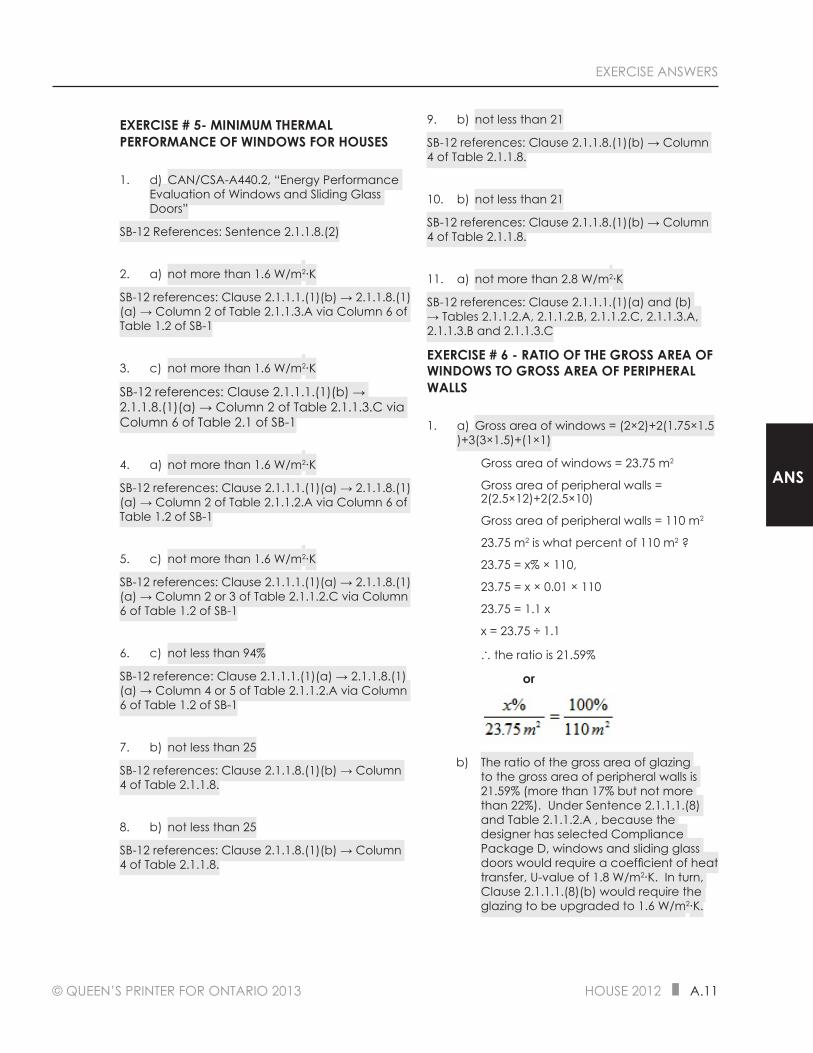
© QUEEN’S PRINTER FOR ONTARIO 2013 HOUSE 2012 A.11
EXERCISE ANSWERS
ANS
EXERCISE # 5- MINIMUM THERMAL PERFORMANCE OF WINDOWS FOR HOUSES
1. d) CAN/CSA-A440.2, “Energy Performance Evaluation of Windows and Sliding Glass Doors”
SB-12 References: Sentence 2.1.1.8.(2)
2. a) not more than 1.6 W/m2∙K
SB-12 references: Clause 2.1.1.1.(1)(b) → 2.1.1.8.(1)(a) → Column 2 of Table 2.1.1.3.A via Column 6 of Table 1.2 of SB-1
3. c) not more than 1.6 W/m2∙K
SB-12 references: Clause 2.1.1.1.(1)(b) → 2.1.1.8.(1)(a) → Column 2 of Table 2.1.1.3.C via Column 6 of Table 2.1 of SB-1
4. a) not more than 1.6 W/m2∙K
SB-12 references: Clause 2.1.1.1.(1)(a) → 2.1.1.8.(1)(a) → Column 2 of Table 2.1.1.2.A via Column 6 of Table 1.2 of SB-1
5. c) not more than 1.6 W/m2∙K
SB-12 references: Clause 2.1.1.1.(1)(a) → 2.1.1.8.(1)(a) → Column 2 or 3 of Table 2.1.1.2.C via Column 6 of Table 1.2 of SB-1
6. c) not less than 94%
SB-12 reference: Clause 2.1.1.1.(1)(a) → 2.1.1.8.(1)(a) → Column 4 or 5 of Table 2.1.1.2.A via Column 6 of Table 1.2 of SB-1
7. b) not less than 25
SB-12 references: Clause 2.1.1.8.(1)(b) → Column 4 of Table 2.1.1.8.
8. b) not less than 25
SB-12 references: Clause 2.1.1.8.(1)(b) → Column 4 of Table 2.1.1.8.
9. b) not less than 21
SB-12 references: Clause 2.1.1.8.(1)(b) → Column 4 of Table 2.1.1.8.
10. b) not less than 21
SB-12 references: Clause 2.1.1.8.(1)(b) → Column 4 of Table 2.1.1.8.
11. a) not more than 2.8 W/m2∙K
SB-12 references: Clause 2.1.1.1.(1)(a) and (b) → Tables 2.1.1.2.A, 2.1.1.2.B, 2.1.1.2.C, 2.1.1.3.A, 2.1.1.3.B and 2.1.1.3.C
EXERCISE # 6 - RATIO OF THE GROSS AREA OF WINDOWS TO GROSS AREA OF PERIPHERAL WALLS
1. a) Gross area of windows = (2×2)+2(1.75×1.5)+3(3×1.5)+(1×1)
Gross area of windows = 23.75 m2
Gross area of peripheral walls = 2(2.5×12)+2(2.5×10)
Gross area of peripheral walls = 110 m2
23.75 m2 is what percent of 110 m2 ?
23.75 = x% × 110,
23.75 = x × 0.01 × 110
23.75 = 1.1 x
x = 23.75 ÷ 1.1
∴ the ratio is 21.59%
or
b) The ratio of the gross area of glazing to the gross area of peripheral walls is 21.59% (more than 17% but not more than 22%). Under Sentence 2.1.1.1.(8) and Table 2.1.1.2.A , because the designer has selected Compliance Package D, windows and sliding glass doors would require a coefficient of heat transfer, U-value of 1.8 W/m2∙K. In turn, Clause 2.1.1.1.(8)(b) would require the glazing to be upgraded to 1.6 W/m2∙K.
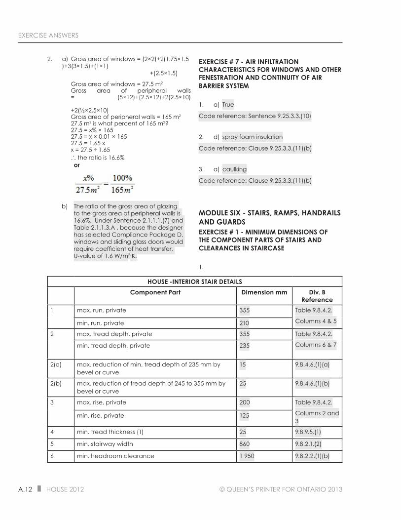
A.12 HOUSE 2012 © QUEEN’S PRINTER FOR ONTARIO 2013
EXERCISE ANSWERS
2. a) Gross area of windows = (2×2)+2(1.75×1.5)+3(3×1.5)+(1×1) +(2.5×1.5)
Gross area of windows = 27.5 m2
Gross area of peripheral walls = (5×12)+(2.5×12)+2(2.5×10) +2(½×2.5×10)Gross area of peripheral walls = 165 m2
27.5 m2 is what percent of 165 m2?27.5 = x% × 16527.5 = x × 0.01 × 16527.5 = 1.65 xx = 27.5 ÷ 1.65∴ the ratio is 16.6%
or
b) The ratio of the gross area of glazing to the gross area of peripheral walls is 16.6%. Under Sentence 2.1.1.1.(7) and Table 2.1.1.3.A , because the designer has selected Compliance Package D, windows and sliding glass doors would require coefficient of heat transfer, U-value of 1.6 W/m2∙K.
EXERCISE # 7 - AIR INFILTRATION CHARACTERISTICS FOR WINDOWS AND OTHER FENESTRATION AND CONTINUITY OF AIR BARRIER SYSTEM
1. a) True
Code reference: Sentence 9.25.3.3.(10)
2. d) spray foam insulation
Code reference: Clause 9.25.3.3.(11)(b)
3. a) caulking
Code reference: Clause 9.25.3.3.(11)(b)
MODULE SIX - STAIRS, RAMPS, HANDRAILS AND GUARDSEXERCISE # 1 - MINIMUM DIMENSIONS OF THE COMPONENT PARTS OF STAIRS AND CLEARANCES IN STAIRCASE
1.
HOUSE -INTERIOR STAIR DETAILSComponent Part Dimension mm Div. B
Reference1 max. run, private 355 Table 9.8.4.2.
Columns 4 & 5min. run, private 210
2 max. tread depth, private 355 Table 9.8.4.2.
Columns 6 & 7min. tread depth, private 235
2(a) max. reduction of min. tread depth of 235 mm by bevel or curve
15 9.8.4.6.(1)(a)
2(b) max. reduction of tread depth of 245 to 355 mm by bevel or curve
25 9.8.4.6.(1)(b)
3 max. rise, private 200 Table 9.8.4.2.
Columns 2 and 3
min. rise, private 125
4 min. tread thickness (1) 25 9.8.9.5.(1)
5 min. stairway width 860 9.8.2.1.(2)
6 min. headroom clearance 1 950 9.8.2.2.(1)(b)
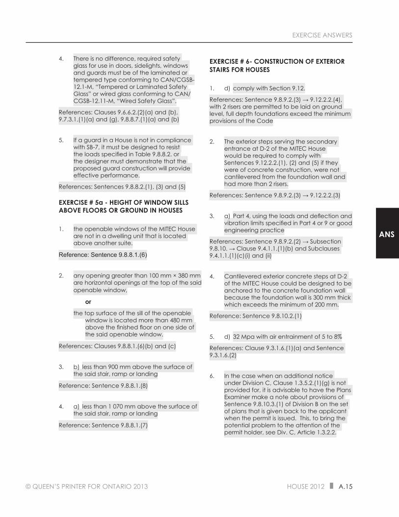
© QUEEN’S PRINTER FOR ONTARIO 2013 HOUSE 2012 A.15
EXERCISE ANSWERS
ANS
4. There is no difference, required safety glass for use in doors, sidelights, windows and guards must be of the laminated or tempered type conforming to CAN/CGSB-12.1-M, “Tempered or Laminated Safety Glass” or wired glass conforming to CAN/CGSB-12.11-M, “Wired Safety Glass”.
References: Clauses 9.6.6.2.(2)(a) and (b), 9.7.3.1.(1)(a) and (g), 9.8.8.7.(1)(a) and (b)
5. If a guard in a House is not in compliance with SB-7, it must be designed to resist the loads specified in Table 9.8.8.2. or the designer must demonstrate that the proposed guard construction will provide effective performance.
References: Sentences 9.8.8.2.(1), (3) and (5)
EXERCISE # 5a - HEIGHT OF WINDOW SILLS ABOVE FLOORS OR GROUND IN HOUSES
1. the openable windows of the MITEC House are not in a dwelling unit that is located above another suite.
Reference: Sentence 9.8.8.1.(6)
2. any opening greater than 100 mm × 380 mm are horizontal openings at the top of the said openable window,
or
the top surface of the sill of the openable window is located more than 480 mm above the finished floor on one side of the said openable window.
References: Clauses 9.8.8.1.(6)(b) and (c)
3. b) less than 900 mm above the surface of the said stair, ramp or landing
Reference: Sentence 9.8.8.1.(8)
4. a) less than 1 070 mm above the surface of the said stair, ramp or landing
Reference: Sentence 9.8.8.1.(7)
EXERCISE # 6- CONSTRUCTION OF EXTERIOR STAIRS FOR HOUSES
1. d) comply with Section 9.12.
References: Sentence 9.8.9.2.(3) → 9.12.2.2.(4), with 2 risers are permitted to be laid on ground level, full depth foundations exceed the minimum provisions of the Code
2. The exterior steps serving the secondary entrance at D-2 of the MITEC House would be required to comply with Sentences 9.12.2.2.(1), (2) and (5) if they were of concrete construction, were not cantilevered from the foundation wall and had more than 2 risers.
References: Sentence 9.8.9.2.(3) → 9.12.2.2.(3)
3. a) Part 4, using the loads and deflection and vibration limits specified in Part 4 or 9 or good engineering practice
References: Sentence 9.8.9.2.(2) → Subsection 9.8.10. → Clause 9.4.1.1.(1)(b) and Subclauses 9.4.1.1.(1)(c)(i) and (ii)
4. Cantilevered exterior concrete steps at D-2 of the MITEC House could be designed to be anchored to the concrete foundation wall because the foundation wall is 300 mm thick which exceeds the minimum of 200 mm.
Reference: Sentence 9.8.10.2.(1)
5. d) 32 Mpa with air entrainment of 5 to 8%
References: Clause 9.3.1.6.(1)(a) and Sentence 9.3.1.6.(2)
6. In the case when an additional notice under Division C, Clause 1.3.5.2.(1)(g) is not provided for, it is advisable to have the Plans Examiner make a note about provisions of Sentence 9.8.10.3.(1) of Division B on the set of plans that is given back to the applicant when the permit is issued. This, to bring the potential problem to the attention of the permit holder, see Div. C, Article 1.3.2.2.

© QUEEN’S PRINTER FOR ONTARIO 2013 HOUSE 2012 A.17
EXERCISE ANSWERS
ANS
2.
DETAILS OF INTERIOR GUARD FOR STAIRWAY OPENING
SERVING A SINGLE DWELLING UNITRef. № & Component Part Dimension Div. B Reference
1 Openings in required guard must prevent the passage of a spherical object having a diameter of:
100 mm 9.8.8.5.(1)
2 Min. height of interior guard 900 mm 9.8.8.3.(2)
Required guards must be designed so that attachments (1) and openings
(1) that could facilitate climbing are not located between:
140 mm and 900 mm above the walking surface
9.8.8.6.(1)
3. b) required
Reference: Clause 9.8.8.1.(1)(a)

A.18 HOUSE 2012 © QUEEN’S PRINTER FOR ONTARIO 2013
EXERCISE ANSWERS
4.
DETAILS OF GUARDS AND HANDRAILS FOR INTERIOR STAIRS SERVING A SINGLE DWELLING UNIT
Ref. № and Component Part Dimension Div. B Reference3 Min. height of top of
handrail865 mm 9.8.7.4.(2)(a)
3 Max. height of handrail 965 mm 9.8.7.4.(2)(b)
4 Min. height of guard on flight of steps
900 mm 9.8.8.3.(4)
Openings in required guard must prevent the passage of a spherical object having a diameter of:
100 mm 9.8.8.5.(1)
Required guards must be designed so that attachments
and openings that could facilitate climbing are not located between:
140 mm and 900 mm above the walking surface
9.8.8.6.(1)
5. b) required
Reference: Clause 9.8.8.1.(1)(a)

A.22 HOUSE 2012 © QUEEN’S PRINTER FOR ONTARIO 2013
EXERCISE ANSWERS
EXERCISE # 6 - SIGNAGE AND LIGHTING OF A SHARED EXIT IN A HOUSE WITH TWO DWELLING UNITS
1. a) the House has a building height of two storeys and a basement
Reference: Clause 9.9.11.3.(1)(a)
2. d) illuminated continuously
Reference: Sentence 9.9.11.3.(3)
3. b) at all times by a light fixture supplied by an electrical circuit
References: Sentence 9.9.11.3.(4)
4. b) 10 lux
Reference: Sentence 9.9.12.3.(4)
5. c) CSA 22.2 № 141-02
References: Sentence 9.9.12.3.(7)
MODULE EIGHT - FIRE PROTECTIONEXERCISE # 1 - AN INTRODUCTION TO FIRE PROTECTION AND OCCUPANCY CLASSIFICATION FOR HOUSES
1. b) Clause 1.4.1.2.(1)(b) of Division A
2. d) 60 degrees or more to the horizontal
Reference: Sentence 9.10.1.2.(1)
3. b) Part 3 of Division B
Reference: Sentence 9.10.1.3.(1)
4. d) extends more than one storey below ground level or exceeds 600 m2 in area
Reference: Sentence 9.10.1.3.(3)
5. a) Part 6
Reference: Sentence 9.10.1.4.(2)
6. d) Group C residential
References: Sentence 9.10.2.1.(1) and Row 1 of Table 9.10.2.1.
EXERCISE # 2 - DETERMINATION OF RATINGS AND BUILDING SIZE FOR HOUSES
1. c) CAN/ULC-S102
References: Sentence 9.10.3.2.(1) → 3.1.12.1.(1), see Subsection 1.3.1.
2. d) Table 3.1.1.A. of SB-2
Reference: Sentence 9.10.3.2.(1)
3. a) the underside
Reference: Sentence 9.10.3.3.(1)
4. a) the underside
Reference: Sentence 9.10.3.3.(1)
5. d) up to three or fewer storeys excluding basement
Reference: Div. A, Clause 1.1.2.4.(1)(a)
6. c) both sides
Reference: Sentence 9.10.3.3.(3)
7. b) it is more than 10% of the area of the dwelling unit
Reference: Clause 9.10.4.1.(1)(a)]
EXERCISE # 3 - CONSTRUCTION TYPES AND PERMITTED OPENINGS IN RATED WALL AND CEILING ASSEMBLIES OF HOUSES
1. d) for electrical and similar outlet boxes provided such outlet boxes are tightly fitted in the opening and offset where they occur on each side of the fire separation
References: Sentences 9.10.5.1. and (3)
2. b) Section 5.3. of SB-2
Reference: Sentence 9.10.5.1.(4)
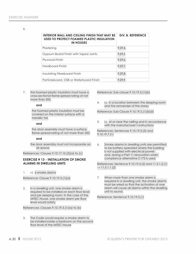
A.30 HOUSE 2012 © QUEEN’S PRINTER FOR ONTARIO 2013
EXERCISE ANSWERS
6.
INTERIOR WALL AND CEILING FINISH THAT MAY BE USED TO PROTECT FOAMED PLASTIC INSULATION
IN HOUSES
DIV. B, REFERENCE
Plastering 9.29.4.
Gypsum Board Finish with Taped Joints 9.29.5
Plywood Finish 9.29.6.
Hardboard Finish 9.29.7.
Insulating Fibreboard Finish 9.29.8.
Particleboard, OSB or Waferboard Finish 9.29.9.
7. the foamed plastic insulation must have a cross-sectional flame-spread rating of not more than 500,
and
the foamed plastic insulation must be covered on the interior surface with a metallic foil,
and
the door assembly must have a surface flame-spread-rating of not more than 200,
and
the door assembly must not incorporate an air space.
References: Clauses 9.10.17.10.(2)(a) to (c)
EXERCISE # 13 - INSTALLATION OF SMOKE ALARMS IN DWELLING UNITS
1. c) 6 smoke alarms
Reference: Clause 9.10.19.3.(1)(a)
2. In a dwelling unit, one smoke alarm is required to be installed on each floor level and per sleeping room. In the case of the MITEC House, one smoke alarm per floor level would satisfy.
References: Clauses 9.10.19.3.(1)(a) to (b)
3. The Code would require a smoke alarm to be installed inside a bedroom on the second floor level of the MITEC House
Reference: Sub-clause 9.10.19.3.(1)(b)
4. b) in a location between the sleeping room and the remainder of the storey
Reference: Sub-Clause 9.10.19.2.(1)(b)(ii)
5. b) at or near the ceiling and in accordance with the manufacturer’s instructions
References: Sentences 9.10.19.3.(3) and 9.10.19.7.(1)
6. Smoke alarms in dwelling units are permitted to be battery operated where the building is not supplied with electrical power; and, during a Part 11 renovation when compliance alternative C175 is used.
References: Sentence 9.10.19.3.(2) and 11.3.1.2.(1) → 11.5.1.1.(2)
7. When more than one smoke alarm is required in a dwelling unit, the smoke alarms must be wired so that the activation of one alarm will cause all alarms within the dwelling unit to sound.
Reference: Sentence 9.10.19.5.(1)
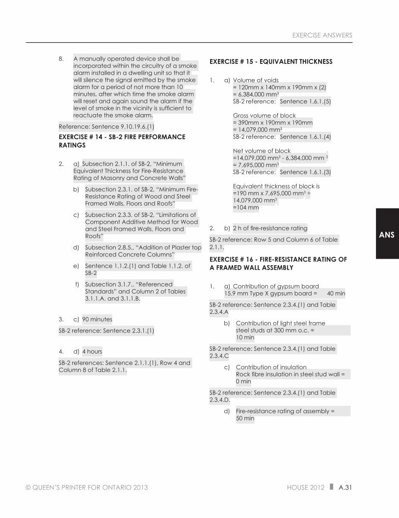
© QUEEN’S PRINTER FOR ONTARIO 2013 HOUSE 2012 A.31
EXERCISE ANSWERS
ANS
8. A manually operated device shall be incorporated within the circuitry of a smoke alarm installed in a dwelling unit so that it will silence the signal emitted by the smoke alarm for a period of not more than 10 minutes, after which time the smoke alarm will reset and again sound the alarm if the level of smoke in the vicinity is sufficient to reactuate the smoke alarm.
Reference: Sentence 9.10.19.6.(1)
EXERCISE # 14 - SB-2 FIRE PERFORMANCE RATINGS
2. a) Subsection 2.1.1. of SB-2, “Minimum Equivalent Thickness for Fire-Resistance Rating of Masonry and Concrete Walls”
b) Subsection 2.3.1. of SB-2, “Minimum Fire-Resistance Rating of Wood and Steel Framed Walls, Floors and Roofs”
c) Subsection 2.3.3. of SB-2, “Limitations of Component Additive Method for Wood and Steel Framed Walls, Floors and Roofs”
d) Subsection 2.8.5., “Addition of Plaster top Reinforced Concrete Columns”
e) Sentence 1.1.2.(1) and Table 1.1.2. of SB-2
f) Subsection 3.1.7., “Referenced Standards” and Column 2 of Tables 3.1.1.A. and 3.1.1.B.
3. c) 90 minutes
SB-2 reference: Sentence 2.3.1.(1)
4. d) 4 hours
SB-2 references: Sentence 2.1.1.(1), Row 4 and Column 8 of Table 2.1.1.
EXERCISE # 15 - EQUIVALENT THICKNESS
1. a) Volume of voids = 120mm x 140mm x 190mm x (2) = 6,384,000 mm3 SB-2 reference: Sentence 1.6.1.(5) Gross volume of block = 390mm x 190mm x 190mm = 14,079,000 mm3 SB-2 reference: Sentence 1.6.1.(4) Net volume of block =14,079,000 mm3 - 6,384,000 mm 3 = 7,695,000 mm3 SB-2 reference: Sentence 1.6.1.(3) Equivalent thickness of block is =190 mm x 7,695,000 mm3 ÷ 14,079,000 mm3 =104 mm
2. b) 2 h of fire-resistance rating
SB-2 reference: Row 5 and Column 6 of Table 2.1.1.
EXERCISE # 16 - FIRE-RESISTANCE RATING OF A FRAMED WALL ASSEMBLY
1. a) Contribution of gypsum board 15.9 mm Type X gypsum board = 40 min
SB-2 reference: Sentence 2.3.4.(1) and Table 2.3.4.A
b) Contribution of light steel frame steel studs at 300 mm o.c. = 10 min
SB-2 reference: Sentence 2.3.4.(1) and Table 2.3.4.C
c) Contribution of insulation Rock fibre insulation in steel stud wall = 0 min
SB-2 reference: Sentence 2.3.4.(1) and Table 2.3.4.D.
d) Fire-resistance rating of assembly = 50 min

A.34 HOUSE 2012 © QUEEN’S PRINTER FOR ONTARIO 2013
EXERCISE ANSWERS
MODULE ELEVEN - DAMPPROOFING, WATERPROOFING AND SOIL GAS CONTROLEXERCISE # 1 - EXTERIOR DAMPPROOFING OF FOUNDATION WALLS
1. Coved with mortar at the intersection of the projection of the footing with the foundation wall when the first course of block is laid and parged on the exterior surface below finished ground level with not less than 6 mm of mortar conforming to Section 9.20.
References: Clauses 9.13.2.4.(1)(a) and (b)
2. all holes and recesses resulting from the removal of ties must be sealed with cement mortar or dampproofing material (on both the exterior and interior surfaces of the foundation wall).
Reference: Sentence 9.13.2.4.(2)
3. a) over the parging (including the coved portion over the footing) below the finished ground level.
Reference: Sentence 9.13.2.5.(1)
b) over the concrete below the finished ground level.
Reference: Sentence 9.13.2.5.(1)
4. d) CAN/CSA-S406-92, “Construction of Preserved Wood Foundations”
References: Sentences 9.13.2.8.(1) and Subsection 1.3.1.
EXERCISE # 2 - INTERIOR DAMPPROOFING OF FOUNDATIONS WALLS AND FLOORS-ON-GROUND
1. b) is not specified
Reference: None
2. 170 ng/(Pa.s.m2) or more.
Reference: Sentence 9.13.2.6.(2)
3. a) Not less than 0.15 mm thick polyethylene sheet or type S roll roofing with joints lapped not less than 100 mm.
References: Sentences 9.13.2.7.(2) and (3)
b) No fewer than 2 mopped-on coats of bitumen, not less than 0.05 mm thick polyethylene sheet or another material providing an equivalent performance.
References: Clauses 9.13.2.7.(4)(a) to (c)
4. When the concrete used for the slab-on-ground has a compressive strength of not less than 25 Mpa after 28 days it shall be deemed that the floor-on-ground is dampproofed and a dampproofing material may be omitted from below and above such slab-on-ground.
Reference: Sentence 9.16.4.5.(1)
EXERCISE # 3 - WATERPROOFING OF EXTERIOR OF FOUNDATIONS WALLS AND FLOORS-ON-GROUND
1. parged on the exterior surface below finished ground level with not less than 6 mm of mortar conforming to Section 9.20.
Reference: Sentence 9.13.3.4.(1)
2. all holes and recesses resulting from the removal of ties must be sealed with mortar or waterproofing material (on both the exterior and interior surfaces of the foundation wall).
Reference: Sentence 9.13.3.4.(2)
3. no fewer than 2 layers of bitumen-saturated membrane, with each layer cemented in place with bitumen and coated overall with a heavy coat of bitumen.
Reference: Sentence 9.13.3.5.(1)
4. have a system of membrane waterproofing provided between 2 layers of concrete, with each slab of concrete not less than 75 mm thick and with the floor membrane mopped to the foundation wall waterproofing membrane to form a complete seal.
Reference: Sentence 9.13.3.6.(1)

© QUEEN’S PRINTER FOR ONTARIO 2013 HOUSE 2012 A.35
EXERCISE ANSWERS
ANS
5. c) CGSB-37-GP-63M, “Cloth, Glass, Coated, for Membrane Waterproofing Systems and Built-Up Roofing”, or “CGSB-37-GP-64M, Mat Reinforcing, Fibrous Glass, for Membrane Waterproofing Systems and Built-Up Roofing”
References: Sentence 9.13.3.3.(1) of Code → Subsection 2.1.1. of CAN/CGSB-37.3-M89
EXERCISE # 4 - SOIL GAS CONTROL AND SB-9
1. the Town of Elliot Lake in the Territorial District of Algoma, the Township of Faraday in the County of Hastings and the geographic Township of Hyman in the Territorial District of Sudbury.
References: Clauses 9.1.1.7.(1)(a), (b) and (c)
3. a) a course of masonry units without voids or flashing material extending across the full width of the masonry units to effectively seal the voids, and with the course of masonry without voids or the flashing located at the level of the adjoining floor and sealed in accordance with Section 3.3. of SB-9, or ground cover required by Article 9.18.6.1. and sealed to said ground cover, in the absence of a floor.
SB-9 references: Clauses 1.1.(1)(a), (b) and 1.1.(2)(a), (b)
b) not less than 100 mm of coarse clean granular material containing not more than 10% of material that will pass a 4 mm sieve and located near the centre of the floor, the depth of the layer of granular material must be increased to 150 mm for a radius of at least 300 mm centred on the position of the pipe required by Sentence 3.2.(2) of SB-9.
SB-9 and Part 9 References: SB-9 Sentences 3.2.(1) and (3) → Sentence 9.16.2.1.(1)
c) not less than 100 mm in diameter, installed in the vertical position through the concrete floor-on-ground such that the bottom end of the pipe is open to the granular drainage layer and its top end extends above the concrete floor-on-ground to provide for the connection of depressurization equipment.
SB-9 references: Clauses 3.2.(2)(a) and (b)
d) equipped with a removable cap seal and labelled to indicate that it is intended only for the removal of soil gas from below the floor-on-ground. e.g., “Use Only for Soil Gas Removal”
SB-9 references: Sentences 3.2.(4) and (5)
4. HC pub 4171 “Guide for Radon Measurements in Residential Dwellings (Homes) 2008”
SB-9 references: Sentence 3.2.(6) and (8)
5. d) the Chief Building Official or the Registered Code Agency having jurisdiction
SB-9 reference: Sentence 3.2.(7)
6. a subfloor depressurization system must be installed to reduce the radon concentration to a level below 200 Bq/m³ in the normal occupancy area.
SB-9 reference: Sentence 3.2.(9)
7. Article 9.32.3.8. of Division B and measures must be taken to ensure that any resultant decrease in soil temperature will not adversely affect the foundations.
SB-9 references: Clauses 3.2.(10)(a) and (b)
EXERCISE # 5 - INSTALLATION OF SOIL GAS BARRIERS FOR FLOORS-ON-GROUND
1. either below the slab or applied to the top of the slab on condition that when the latter is the case, a separate floor is installed over the concrete floor-on-ground.
SB-9 references: Clauses 3.1.(1)(a) and (b)
2. When the soil gas barrier is installed below the concrete slab on-ground, the joints must be lapped not less than 300 mm and when the soil gas barrier is installed above the concrete slab on-ground, the joints must be sealed.
SB-9 references: Sentences 3.1.(2) and (3)
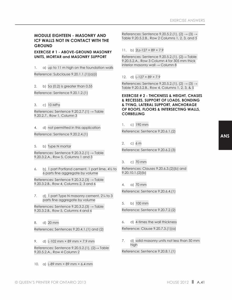
© QUEEN’S PRINTER FOR ONTARIO 2013 HOUSE 2012 A.41
EXERCISE ANSWERS
ANS
MODULE EIGHTEEN - MASONRY AND ICF WALLS NOT IN CONTACT WITH THE GROUNDEXERCISE # 1 - ABOVE-GROUND MASONRY UNITS, MORTAR and MASONRY SUPPORT
1. a) up to 11 m high on the foundation walls
Reference: Subclause 9.20.1.1.(1)(a)(i)
2. b) Sa (0.2) is greater than 0.55
Reference: Sentence 9.20.1.2.(1)
3. c) 10 MPa
References: Sentence 9.20.2.7.(1) → Table 9.20.2.7., Row 1, Column 3
4. d) not permitted in this application
Reference: Sentence 9.20.2.4.(1)
5. b) Type N mortar
References: Sentence 9.20.3.2.(1) → Table 9.20.3.2.A., Row 5, Columns 1 and 3
6. b) 1 part Portland cement, 1 part lime, 4½ to 6 parts fine aggregate by volume
References: Sentence 9.20.3.2.(3) → Table 9.20.3.2.B., Row 4, Columns 2, 3 and 6
7. d) 1 part Type N masonry cement, 2¼ to 3 parts fine aggregate by volume
References: Sentence 9.20.3.2.(3) → Table 9.20.3.2.B., Row 5, Columns 4 and 6
8. d) 20 mm
References: Sentences 9.20.4.1.(1) and (2)
9. d) L-102 mm × 89 mm × 7.9 mm
References: Sentence 9.20.5.2.(1), (2)→ Table 9.20.5.2.A., Row 4 Column 2
10. a) L-89 mm × 89 mm × 6.4 mm
References: Sentence 9.20.5.2.(1), (2) → (3) → Table 9.20.5.2.B., Row 2 Columns 1, 2, 3, and 5
11. b) 2Ls-127 × 89 × 7.9
References: Sentence 9.20.5.2.(1), (2)→ Table 9.20.5.2.A., Row 3 Column 4 for 305 mm thick interior masonry wall → Column 8
12. d) L-127 × 89 × 7.9
References: Sentence 9.20.5.2.(1), (2) → (3) → Table 9.20.5.2.B., Row 4, Columns 1, 2, 3, & 5
EXERCISE # 2 - THICKNESS & HEIGHT, CHASES & RECESSES, SUPPORT OF LOADS, BONDING & TYING, LATERAL SUPPORT, ANCHORAGE OF ROOFS, FLOORS & INTERSECTING WALLS, CORBELLING
1. c) 190 mm
Reference: Sentence 9.20.6.1.(2)
2. c) 6 m
Reference: Sentence 9.20.6.2.(3)
3. c) 70 mm
References: Clauses 9.20.6.3.(2)(b) and 9.20.10.1.(2)(b)
4. a) 70 mm
Reference: Sentence 9.20.6.4.(1)
5. b) 100 mm
Reference: Sentence 9.20.7.2.(2)
6. d) 4-times the wall thickness
Reference: Clause 9.20.7.3.(1)(a)
7. d) solid masonry units not less than 50 mm high
Reference: Sentence 9.20.8.1.(1)

© QUEEN’S PRINTER FOR ONTARIO 2013 HOUSE 2012 A.43
EXERCISE ANSWERS
ANS
9. d) CSA A371, “Masonry Construction for Buildings”
Reference: Sentence 9.20.15.2.(1), see Subsection 1.3.1.
10. c) ASTM A123 / A123M and a coating of 610 g/m2
References: Sentence 9.20.16.1.(1) and Table 9.20.16.1., Row 3, see Subsection 1.3.1.
EXERCISE # - 4 ABOVE-GROUND FLAT ICF WALLS
1. c) 140 mm
Reference: Clause 9.20.17.1.(1)(a)
2. d) 10M bars at not more than 600 mm o.c. vertically
Reference: Subclause 9.20.17.2.(1)(a)(ii)
3. c) 10M bars at not more than 400 mm o.c. horizontally
Reference: Clause 9.20.17.2.(2)(a)
4. d) 1 200 mm of corners
Reference: Sentence 9.20.17.3.(1)
5. d) 1-10M bar at the top and 1-10M bar at the bottom of the opening
Reference: Sentence 9.20.17.3.(3)
6. b) 900 mm
References: Sentence 9.20.17.4.(2)
7. d) of not less than 12.7 mm in diameter and embedded not less than 100 mm into the concrete and spaced not more than 1 200 mm o.c.
References: Clauses 9.20.17.6.(1)(a) and (b) and Sentence 9.20.17.6.(2)
8. d) more than 1 200 mm in width
Reference: Sentence 9.20.17.4.(4)
9. d) 3-82 mm nails, toe-nailed at each truss
References: Sentence 9.20.17.6.(3) → Table 9.23.3.4., Row 19
10. d) staggered 12.7 mm anchor bolts that are not more than 275 mm apart
Reference: Clause 9.20.17.5.(3)(b) → Table 9.20.17.5., Row 4, Columns 1 and 2
MODULE NINETEEN - CHIMNEYS AND FLUESEXERCISE # 1 CHIMNEY AND APPLIANCE VENTING TERMINOLOGY
1. Appliance, 2. Breeching, 3. Chimney, 6. Flue Collar, 7. Flue Pipe
EXERCISE # 2 MASONRY, CONCRETE AND FACTORY-BUILT CHIMNEYS FOR SOLID-FUEL-BURNING APPLIANCES AND OTHER AUTHORITIES HAVING JURISDICTION IN THE CASE OF GAS, PROPANE AND OIL-BURNING APPLIANCES
1. b) not more than 120 kW
Reference: Clause 9.21.1.1.(1)(a)
2. a) CAN/ULC-S629-M, “650°C Factory-Built Chimneys”
Reference: Sentence 9.21.1.2.(1), see Subsection 1.3.1.
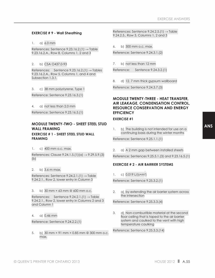
© QUEEN’S PRINTER FOR ONTARIO 2013 HOUSE 2012 A.55
EXERCISE ANSWERS
ANS
EXERCISE # 9 - Wall Sheathing
1. a) 6.0 mm
References: Sentence 9.23.16.2.(1) → Table 9.23.16.2.A., Row 8, Columns 1, 2 and 3
2. b) CSA O437.0-93
References: Sentence 9.23.16.2.(1) → Tables 9.23.16.2.A., Row 5, Columns 1, and 4 and Subsection 1.3.1.
3. c) 38 mm polystyrene, Type 1
Reference: Sentence 9.23.16.3.(1)
4. a) not less than 2.0 mm
Reference: Sentence 9.23.16.5.(1)
MODULE TWENTY-TWO - SHEET STEEL STUD WALL FRAMINGEXERCISE # 1 - SHEET STEEL STUD WALL FRAMING
1. c) 400 mm o.c. max.
References: Clause 9.24.1.5.(1)(a) → 9.29.5.9.(3)(b)
2. b) 3.6 m max.
References: Sentence 9.24.2.1.(1) → Table 9.24.2.1., Row 2, lower entry in Column 3
3. b) 30 mm × 63 mm @ 600 mm o.c.
References: Sentence 9.24.2.1.(1) → Table 9.24.2.1., Row 2, lower entry in Columns 2 and 3 and Column 1
4. a) 0.46 mm
Reference: Sentence 9.24.2.2.(1)
5. b) 30 mm × 91 mm × 0.85 mm @ 300 mm o.c. max.
References: Sentence 9.24.2.5.(1) → Table 9.24.2.5., Row 3, Columns 1, 2 and 3
6. b) 300 mm o.c. max.
Reference: Sentence 9.24.3.1.(2)
7. b) not less than 12 mm
Reference: Sentence 9.24.3.2.(1)
8. d) 12. 7 mm thick gypsum wallboard
Reference: Sentence 9.24.3.7.(3)
MODULE TWENTY-THREE - HEAT TRANSFER, AIR LEAKAGE, CONDENSATION CONTROL, RESOURCE CONSERVATION AND ENERGY EFFICIENCYEXERCISE #1
1. b) The building is not intended for use on a continuing basis during the winter months
Reference: Sentence 9.25.1.1.(1)
2. a) A 2 mm gap between installed sheets
Reference: Sentences 9.25.5.1.(3) and 9.23.16.5.(1)
EXERCISE # 2 - AIR BARRIER SYSTEMS
1. c) 0.019 L/(s×m2)
Reference: Sentence 9.25.3.2.(1)
2. a) by extending the air barrier system across the intersection
Reference: Sentence 9.25.3.3.(4)
3. d) Non-combustible material at the second floor ceiling that is taped to the air barrier system and caulked to the vent with high temperature caulking
Reference: Sentence 9.25.3.3.(14)

A.56 HOUSE 2012 © QUEEN’S PRINTER FOR ONTARIO 2013
EXERCISE ANSWERS
4. a) True
References: Sentences 9.25.3.4.(1) and 9.25.4.1.(1)
EXERCISE #3 - Vapour Barriers
1. b) prevent condensation due to water vapour diffusion in a wall space, floor space, attic space or roof space
References: Sentence 9.25.4.1.(1) and definition of vapour barrier in Clause 1.4.1.2.(1)(b) of Division A
2. b) 60 ng/(Pa×s×m2)
Reference: Sentence 9.25.4.2.(1)
3. a) close to warm side of insulation, to prevent condensation in the assembly
Reference: Sentence 9.25.4.3.(2)
EXERCISE #4 - Properties and Position of Materials in Building Envelope
1. b) Shall be designed according to Part 5
Reference: Sentence 9.25.5.1.(2)
EXERCISE #5 - Position of Low Permeance Materials
1. d) 0.35
References: Note (1) of Table 9.25.5.2. → Col 6 of Table of SB-1, 6100 DD → Row 3 Col. 2, Table 9.25.5.2.
EXERCISE #6 - Energy Efficiency Design
1. b) If the building is intended for occupancy on a continuing basis during the winter months only
Reference: [Sentence 12.2.1.1.(3)]
EXERCISE # 7 - LEVELS OF INSULATION FOR HOUSES
1. c) RSI 4.23
SB-12 References: Clause 2.1.1.1.(1)(a) via Table 1.2 of SB-1 → 2.1.1.2.(1) → Table 2.1.1.2.A, Row 4, Column 2
2. d) RSI 2.10
SB-12 References: Sentence 2.1.1.1.(1) → 2.1.1.5.(1)
3. b) not less than 50 mm above the crawl space floor
Reference: Div. B, Sentence 9.25.2.3.(4)
4. b) in an attic space over a ceiling sloped at 1.5 in 12
Reference: Div. B, Clause 9.25.2.4.(2)(b)
MODULE TWENTY-FOUR - ROOFINGEXERCISE # 1 - ROOFING MATERIALS AND SLOPES
1. a) True
Reference: Sentence 9.26.1.1.(1)
2. b) False
References: Sentences 9.26.1.1.(2) and A-9.26.1.1.(2)
3. c) may be installed in accordance with the methods described in CAN3-A123.52-M
References: Sentence 9.26.1.2.(1), see Subsection 1.3.1.
4. c) CSA A123.1 / A123.5
References: Clause 9.26.2.1.(1)(l), see Subsection 1.3.1.
5. d) 19 mm long, 1.6 mm in diameter with a 25 mm crown
Reference: Sentence 9.26.2.3.(2)