module 1 railway planning · 1.11 recommended questions 1.12 outcomes 1.13 further reading ... by...
TRANSCRIPT
Railways, Harbour, Tunnelling and Airports 15CV552
Department of Civil Engineering, ATMECE, Mysuru Page 1
Module – 1Railway Planning
Structure1.0 Introduction1.1 Objectives1.2 Elements of permanent way1.3 Rails1.4 Sleepers1.5 Ballast1.6 Track fittings and fastenings1.7 Track Stress1.8 Route alignment surveys1.9 Geometric Design of Track1.10 Points and Crossings1.11 Recommended questions1.12 Outcomes1.13 Further Reading
1.0 IntroductionDifferent Modes of Transport: Our environment consists of land, air, and water. Thesemedia have provided scope for three modes of transport-land transport, air transport andwater transport. Rail transport and road transport are the two components of land transport.Each mode of transport, depending upon its various characteristics, has intrinsic strengths andweaknesses.
1.1 Objectives Understand the history and development, role of railways, railway planning and
development based on essential criteria’s.
Significance of Road, Rail, Air and Water transports – Coordination of all modes toachieve sustainabilityRail transport Owing to the heavy expenditure on the basic infrastructure required, railtransport is best suited for carrying bulk commodities and a large number of passengers overlong distances. This is the most commonly used and cost effective long distance transportsystem of the country.Road transport Owing to flexibility of operation and the ability to provide door-to-doorservice, road transport is ideally suited for carrying light commodities and a small number ofpassengers over short distances. The importance of roads in connecting the vast rural areas ofIndia to form the national market and economy cannot be overstated. Connectivity providedby roads is perhaps the single most important determinant of well being and the quality of lifeof people living in an urban area. The efficiency of the innumerable government programmesaimed at rural development, employment generation, and local industrialization is, to largeextent, determined by the connectivity provided by roads.
Railways, Harbour, Tunnelling and Airports 15CV552
Department of Civil Engineering, ATMECE, Mysuru Page 2
Air transport Owing to the heavy expenditure on the sophisticated equipment required andthe high fuel costs, air transport is better suited for carrying passengers or goods that have toreach their destinations in a very short period of time. Air transport is an integral part oftransport infrastructure and a significant sector of the economy. Airports are recognized fortheir ability to multiply business activity in their proximity and stimulate furtherdevelopment. Aviation creates a large number of jobs.
Water transport Owing to low cost of infrastructure and relatively slow speeds, watertransport is best suited for carrying heavy and bulky goods over long distances, providedthere is no consideration of the time factor. Water transport is the cheapest and the oldestmode of transport. It operates on a natural track and hence does not require huge capitalinvestment in the construction and maintenance of its track except in case of canals. The costof operation of water transport is also very less. It has the largest carrying capacity and ismost suitable for carrying bulky goods over long distances. It has played a very significantrole in bringing different parts of the world closer and is indispensable to foreign trade.
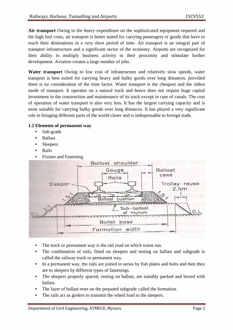
1.2 Elements of permanent way• Sub-grade• Ballast• Sleepers• Rails• Fixture and Fastening
• The track or permanent way is the rail road on which trains run.• The combination of rails, fitted on sleepers and resting on ballast and subgrade is
called the railway track or permanent way.• In a permanent way, the rails are joined in series by fish plates and bolts and then they
are to sleepers by different types of fastenings.• The sleepers properly spaced, resting on ballast, are suitably packed and boxed with
ballast.• The layer of ballast rests on the prepared subgrade called the formation.• The rails act as girders to transmit the wheel load to the sleepers.
Railways, Harbour, Tunnelling and Airports 15CV552
Department of Civil Engineering, ATMECE, Mysuru Page 2
Air transport Owing to the heavy expenditure on the sophisticated equipment required andthe high fuel costs, air transport is better suited for carrying passengers or goods that have toreach their destinations in a very short period of time. Air transport is an integral part oftransport infrastructure and a significant sector of the economy. Airports are recognized fortheir ability to multiply business activity in their proximity and stimulate furtherdevelopment. Aviation creates a large number of jobs.
Water transport Owing to low cost of infrastructure and relatively slow speeds, watertransport is best suited for carrying heavy and bulky goods over long distances, providedthere is no consideration of the time factor. Water transport is the cheapest and the oldestmode of transport. It operates on a natural track and hence does not require huge capitalinvestment in the construction and maintenance of its track except in case of canals. The costof operation of water transport is also very less. It has the largest carrying capacity and ismost suitable for carrying bulky goods over long distances. It has played a very significantrole in bringing different parts of the world closer and is indispensable to foreign trade.
1.2 Elements of permanent way• Sub-grade• Ballast• Sleepers• Rails• Fixture and Fastening
• The track or permanent way is the rail road on which trains run.• The combination of rails, fitted on sleepers and resting on ballast and subgrade is
called the railway track or permanent way.• In a permanent way, the rails are joined in series by fish plates and bolts and then they
are to sleepers by different types of fastenings.• The sleepers properly spaced, resting on ballast, are suitably packed and boxed with
ballast.• The layer of ballast rests on the prepared subgrade called the formation.• The rails act as girders to transmit the wheel load to the sleepers.

Railways, Harbour, Tunnelling and Airports 15CV552
Department of Civil Engineering, ATMECE, Mysuru Page 3
• The sleepers hold the rails in proper position with respect to the proper tilt, gauge andlevel, and transmit the load from rails to the ballast.
• The ballast distributes the load over the formation and holds the sleepers in position.• On curved tracks, super elevation is maintained by ballast and the formation is
levelled. Minimum cushion is maintained at the inner rail, while the outer rail getskept more ballast cushion.
• Permanent track is regarded to be semi-elastic in nature.• There is possibility of track getting disturbed by the moving wheel loads.• The track should be therefore be constructed and maintained keeping the requirements
of a permanent way, in view, so as to achieve higher speed and better riding qualitieswith less future maintenance.
Following are some of the basic requirements of a permanent way:• The gauge should be correct and uniform.• The rails should be in proper level. In a straight track, two rails must be at the same
level. On curves, the outer rail should have proper super elevation and there should beproper transition at the junction of a straight and a curve.
• The alignment should be correct i.e., it should be free from irregularities.• The gradient should be uniform and as gentle as possible. Any change of gradient
should be followed by a smooth vertical curve, to give smooth riding quality.• The track should be resilient and elastic in order to adsorb shocks and vibrations of
running tracks.• The radii and super elevation on curves should be properly designed and maintained.• Drainage system must be perfect for enhancing safety and durability of track.• Joints, including points and crossings which are regarded to be weakest points of the
railway track, should be properly designed and maintained.• There should be adequate provision for easy renewals and replacements.• The track structure should be strong, low in initial cost as well as maintenance cost.• The various components of track i.e., rails, fittings, sleepers, ballast and formation
must fully satisfy the requirements for which they have been provided. If anycomponent is lacking in fulfilling its requirements then either it should be improved orreplaced.
Choice of Gauge: The choice of gauge is very limited, as each country has a fixed gauge andall new railway lines are constructed to adhere to the standard gauge. However, the followingfactors theoretically influence the choice of the gauge.Cost Considerations: There is only a marginal increase in the cost of the track if a widergauge is adopted. In this connection, the following points are important.(a) There is a proportional increase in the cost of acquisition of land, earthwork, rails,sleepers, ballast, and other track items when constructing a wider gauge.(b) The cost of building bridges, culverts, and tunnels increases only marginally due to awider gauge.(c) The cost of constructing station buildings, platforms, staff quarters, level crossings,signals, etc. associated with the railway network is more or less the same for all gauges.

Railways, Harbour, Tunnelling and Airports 15CV552
Department of Civil Engineering, ATMECE, Mysuru Page 4
(d) The cost of rolling stock is independent of the gauge of the track for carrying the samevolume of traffic.
Traffic Considerations: The volume of traffic depends upon the size of wagons and thespeed and hauling capacity of the train.(a) As a wider gauge can carry larger wagons and coaches, it can theoretically carry moretraffic.(b) A wider gauge has a greater potential at higher speeds, because speed is a function of thediameter of the wheel, which in turn is limited by the width of the gauge.(c) The type of traction and signalling equipment required are independent of the gauge.
Physical Features of the Country: It is possible to adopt steeper gradients and sharpercurves for a narrow gauge as compared to a wider gauge.
Uniformity of Gauge: The existence of a uniform gauge in a country enables smooth,speedy, and efficient operation of trains. Therefore a single gauge should be adoptedirrespective of the minor advantages of a wider gauge and the few limitations of a narrowergauge.
1.3 Rails• Rails on the track can be considered as steel girders for the purpose of carrying axle
loads.• They are made of high carbon steel to withstand wear and tear.
Types of RailsThe rails used in the construction of railway track are of following types:1. Double headed rails (D.H Rails)2. Bull headed rails (B.H Rails)3. Flat footed rails (F.F Rails)
Double headed railsThe rail sections, whose foot and head are of same dimensions, are called Double
headed or Dumb-bell rails. In the beginning, these rails were widely used in the railway track.
Railways, Harbour, Tunnelling and Airports 15CV552
Department of Civil Engineering, ATMECE, Mysuru Page 5
The idea behind using these rails was that when the head had worn out due to rubbing actionof wheels, the rails could be inverted and reused. But by experience it was found that theirfoot could not be used as running surface because it also got corrugated under the impact ofwheel loads. This type of rail is not in use in Indian Railways now-a day.
Bull headed railsThe rail section whose head dimensions are more than that of their foot are called bull
headed rails. In this type of rail the head is made little thicker and stronger than the lower partby adding more metal to it. These rails also require chairs for holding them in position. Bullheaded rails are especially used for making points and crossings.
Merits(i) B.H. Rails keep better alignment and provide smoother and stronger track.(ii) These rails provide longer life to wooden sleepers and greater stability to the track.(iii) These rails are easily removed from sleepers and hence renewal of track is easy.
Demerits(i) B.H. rails require additional cost of iron chairs.(ii) These rails require heavy maintenance cost.(iii) B.H. rails are of less strength and stiffness.
Flat footed railsThe rail sections having their foot rolled to flat are called flat footed or vignole`s rails.
This type of rail was invented by Charles Vignole in 1836. It was initially thought that the flatfooted rails could by fixed directly to wooden sleepers and would eliminate chairs and keysrequired for the B.H. rails. But later on, it was observed that heavy train loads caused the footof the rail to sink into the sleepers and making the spikes loose. To remove this defect, steelbearing plates were used in between flat footed rails and the wooden sleeper. These rails aremost commonly used in India.
Merits(i) F.F. rails have more strength and stiffness.(ii) No chairs are required for holding them in position.(iii) These rails require less number of fastenings.(iv) The maintenance cost of track formed with F.F. rails is less.
Demerits(i) The fittings get loosened more frequently.(ii) These rails are not easily removed and hence renewal of track becomes difficult.(iii) It is difficult to manufacture points and crossings by using these rails.Functions of rails
1. Rails provide a hard, smooth and unchanging surface for passage of heavy movingloads with a maximum friction between the steel rails and steel wheels.
2. Rails bear the stresses developed due to heavy vertical loads, lateral and brakingforces and thermal stresses.
3. The rail material used is such that it gives minimum wear to avoid replacementcharges and failures of rails due to wear.

Railways, Harbour, Tunnelling and Airports 15CV552
Department of Civil Engineering, ATMECE, Mysuru Page 6
4. Rails transmit the loads to sleepers and consequently reduce pressure on ballast andformation below.
Composition of rail steel• For ordinary rails: high carbon steel• For rails on points and crossing: medium carbon steel
Requirements of Rails1. They should be of proper composition of steel and should be manufactured by open
fireplace or duplex process.2. The vertical stiffness should be high enough to transmit the load to several sleepers
underneath. The height of rail should therefore adequate.3. Rails should be capable of withstanding lateral forces. Large width of head and foot
endows the rails with high lateral stiffness.4. The head must be sufficiently deep to allow for an adequate margin of vertical wear.
The wearing surface should be hard.5. Web of rails should be sufficiently thick to bear the load coming on it and should
provide adequate flexural rigidity.6. Foot should be wide enough so that rails are stable against overturning especially on
curves.7. Bottom of the head and top of the foot of rails should be so shaped as to enable the
fish plates to transmit the vertical load efficiently from the head to the foot at railjoints.
8. Relative distribution of material of rail in head, web and foot must be balanced forsmooth transmission of loads.
9. The centre of gravity of the rail section must lie approximately at mid height so thatmaximum tensile and compressive stresses are equal.
10. The tensile strength of the rail piece should not be less than 72kg/m2.
1.4 Sleepers and Ballast:Sleepers:
Sleepers are members generally laid transverse to the rails on which the rails aresupported and fixed, to transfer the loads from rails to the ballast and subgrade below.
Functions of sleepers1. To hold the rails to correct gauge.2. To hold the rails in proper level or transverse tilt so as to provide a firm and even
supports to rails.3. To act as an elastic medium in between the ballast and rails to absorb the blows and
vibrations of moving loads.4. To distribute the load from the rails to the index area of ballast underlying it or to the
girders in case of bridges.

Railways, Harbour, Tunnelling and Airports 15CV552
Department of Civil Engineering, ATMECE, Mysuru Page 7
5. Sleepers also add to the longitudinal and lateral stability of the permanent track on thewhole.
6. They also provide means to rectify track geometry during service life.
Requirements of sleepers1. The sleepers to be used should be economical i.e., they should have minimum
possible initial and maintenance costs.2. The fittings of the sleepers should be such that they can be easily adjusted during
maintenance operations such as easy lifting, packing, removal and replacement.3. The weight of sleepers should not be too heavy or excessively light i.e., they should
have moderate weight for ease of handling.4. The design of sleepers should be such that the gauge, alignment of track and levels of
the rails can be easily adjusted and maintained.5. The bearing area of sleepers below the rail seat and over the ballast should be enough
to resist the crushing due to rail seat and crushing of the ballast underneath thesleeper.
6. The sleeper design and spacing should be such as to facilitate easy removal andreplacement of ballast.
7. The sleepers should be capable of resisting shocks and vibrations due to passing ofheavy loads of high speed trains.
8. The design of the sleepers should be such that they are not damaged during packingprocesses.
9. The design of sleepers should be such that they are not pushed out easily due tomoving trains especially with steel sleepers.
Classification of sleepers1. Wooden sleepers2. Metal sleepers
a. Cast-iron sleepersb. Steel sleepers
3. Concrete sleepersa. Reinforced concrete sleepersb. Pre-stressed concrete sleepers
Wooden/Timber Sleepers• Wooden sleepers are regarded to be best as they fulfill almost all the requirements of
ideal sleeper.• Their life depends upon their ability to resist wear, decay, attack by vermin (white
ants) and quality of timber used.Advantages:
– Timber is easily available in all the parts of India.– Fittings for wooden sleepers are few and simple in design.– These sleepers are able to resist shocks and vibrations due to heavy moving loads and
also give less noisy track.
Railways, Harbour, Tunnelling and Airports 15CV552
Department of Civil Engineering, ATMECE, Mysuru Page 8
– These are easy to lay, relay, pack, lift and maintain.– These are suitable for all types of ballast.– Wooden sleepers are over-all economical.
Disadvantages:– These sleepers are subjected to wear, decay, attack by white ants, warping, cracking,
end splitting, rail cutting etc.– It is difficult to maintain gauge in the case of wooden sleepers.– Track is easily disturbed.– Wooden sleepers have got minimum service life (12-15 years) as compared to other
types.– Maintenance cost of wooden sleepers is highest as compared to other types.
Metal Sleepers• Due to growing scarcity of wooden sleepers, high cost and short life metal sleepers
were being used.• Metal sleepers are either of cast-iron or steel. Cast-iron is in greater use because of its
resistance to corrosion.Advantages:
– Metal sleepers are uniform in strength and durability.– In metal sleepers, the performance of fittings is better and hence lesser creep occurs.– Metal sleepers are economical as life is longer and maintenance is easier.– Gauge can be easily adjusted and maintained.– Frequent renewal is not required.– Have good scrap value, easy to manufacture and not susceptible to fire hazards.
Disadvantages:o More ballast is required than other types of sleepers.o Fittings required are greater in number and difficult to maintain/inspect.o They are liable to rusting/corrosion.o Metal being good conductor of electricity interferes with track circuiting.o They are unsuitable for bridges, level crossings and in case of points and crossings.o These are only suitable for stone ballast and for rails which they are manufactured.
Concrete SleepersThese are made of strong homogenous material, impervious to effects of moisture, and
is unaffected by the chemical attack of atmospheric gases or subsoil salts.These can easily moulded to size and shape required to withstand stresses produced by
fast and heavy traffic.Advantages:
o These are free from natural decay and attack by vermin etc.o They have maximum life as compared to others (40-60 years)o These are not affected by moisture, chemical action of ballast and subsoil salts.o There is no difficulty in track circuiting of electrified tracks.o Increased weight helps to reduces joint maintenance, greater stability of track and
better resistance against temperature variation.

Railways, Harbour, Tunnelling and Airports 15CV552
Department of Civil Engineering, ATMECE, Mysuru Page 9
o These have higher elastic modulus and hence can withstand the stresses induced byfast and heavy traffic.
o They offer an ideal track in respect of gauge, cross-level and alignment.Disadvantages:o The weight of concrete sleeper is as high as 2.5 to 3 times of wooden sleeper, requiring
the mechanical appliances for handling.o These require pads and plugs for spikes.o They damage the bottom edge during packing.o The scrap value is almost nil.o The damages to the concrete sleepers are very heavy in case of derailment.
Spacing of sleepers and sleeper density• The space between two adjacent sleepers determines the effective span of the rail over
the sleepers.• The spacing of sleepers, therefore in a track depends on the axle load which the track is
expected to carry and lateral thrust of locomotives to which it is subjected.• The number of sleepers in a track is indicated by the number per rail length.• Since sleeper also provides lateral stability to the track, so more the number of sleepers
more is the lateral stability.• The number of sleepers however cannot be increased indefinitely as certain minimum
space between sleepers is required for packing of ballast.• In India, this minimum distance for manual packing of ballast is kept 30.5cm to 35.5cm• The number of sleepers per rail varies in India from M+4 to M+7 for main tracks,
where M= length of rail in metres.• Sleeper density is the number of sleepers per rail length and it is specified as M+x or
N+x, where M is the length of the rail in metres( N is the length of rail in yards) and xis a number, varying according to the factors.
• Factors governing the sleeper density are: axle load, speed, type and section of the rails,type of ballast and ballast cushion, type and strength of sleepers and nature offoundation.
1.5 Ballast• It is the granular material usually broken stone or brick, shingle or kankar, gravel or
sand placed and packed below and around the sleepers to transmit load from sleepers,to formation and at the same time allowing drainage of the track.
• It provides a suitable foundation for the sleepers and also hold the sleepers in theircorrect level and position, preventing their displacement by lateral or longitudinalthrusts.
• The lateral stability of track depends on the ballast.
Functions of ballast• It transfers the load from the sleeper to the subgrade and then distributes it uniformly
over a larger area of the formation.
Railways, Harbour, Tunnelling and Airports 15CV552
Department of Civil Engineering, ATMECE, Mysuru Page 10
• It holds the sleepers in position and prevents the lateral and longitudinal movement,due to dynamic loads and vibrations of moving trains.
• It imparts some degree of elasticity of the track.• It provides easy means of maintaining the correct levels of the two lines of a track and
for correcting track alignment.• It provides good drained foundation immediately below the sleepers and helps to
protect the top surface of the formation. This is achieved by providing coarseand rough aggregates with plenty of voids.
Requirements of the good ballast It should be able to withstand hard packing without disintegrating. In other words it
should resist crushing under dynamic loads. It should not make the track dusty or muddy due powder under dynamic wheel loads but
should be capable of being cleaned to provide good drainage. It should allow for easy drainage with minimum soakage and the voids should be large
enough to prevent capillary action. It should offer resistance to abrasion and weathering. Abrasion means wear due rubbing
action of particles with each other and weathering means cracking and shattering of thematerial due to variation in temperature, moisture and freezing.
It should retain its position laterally and longitudinally under all conditions of traffic,particularly on curves, where it should be able to prevent transverse displacement ofsleepers.
It should not produce any chemical action in rail and metal sleepers The size of stone ballast should be 5cm for wooden sleepers, 4cm for metal sleepers and
2.5cm for turnouts and crossovers. The materials should be easily workable by means of the implements in use. The ballast should be available in nearby quarries so that it reduces the cost of supply. It
should also fulfil the requirements of quality, amount of traffic, life and maintenance cost.
Types of ballast Broken stone Gravel or river pebbles or shingle Ashes or cinders
Sand Moorum
Kankar Brick ballast Blast furnace slag
Selected earth
Size and section of ballast• The size of the ballast varies from 1.9cm to 5.1cm
Railways, Harbour, Tunnelling and Airports 15CV552
Department of Civil Engineering, ATMECE, Mysuru Page 11
• Stones of larger size are not desirable and the maximum size as 5.1cm is preferable asinterlocking of stones of this size is better than that of stone of larger sizes.
• The best ballast is that which contains stones varying in size from 1.9cm to 5.1cmwith reasonable proportion of intermediate sizes.
• The size of stone ballast should be 5cm for wooden sleepers, 4cm for metal sleepersand 2.5cm for turnouts and crossovers.
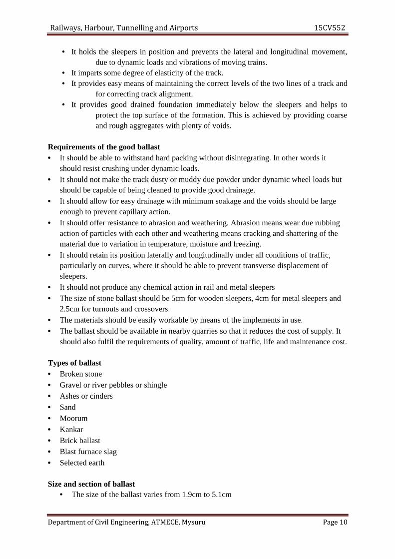
• The section of ballast layer consists of depth of ballast under the sleepers and thewidth of the ballast layer.
• The depth of the ballast under the sleepers is an important factor in the load bearingcapacity and uniformity of distribution of load.
• In America, a depth of ballast equivalent to the sleeper spacing is recommended,because of heavier loads and the closer spacing of sleepers being used in that country.
• In India, this recommendation will give unnecessarily thicker layer of ballast due tolarge spacing of sleepers being used.
• The width of the ballast layer is also important as the lateral strength of track dependspartly upon the quantity of ballast used at the ends of the sleepers.
• The lateral strength increases with increase in width of ballast layer but there is a limitbeyond which no useful purpose is served by widening.
• This width limit is at 38cm to 43cm from the end of this sleepers as computed.• Although the lines of equal pressure in ballast through wheel loads are in the shape of
a bulb yet simplicity purpose, the load dispersion can be assumed at 45° to thevertical.
• For uniform distribution of load on the formation, the depth of ballast should be suchthat the dispersion lines do not overlap each other.
1.6 Track fittings and fasteningsTrack fittings and fastenings are fittings requires for joining of rails end to end and also forfixing the rails to sleepers in a track.
Functions of track fittings and fasteningsRail fixtures and fastenings have the following functions:(i) To join the rails end to end to form full length of track.(ii) To fix the rails to sleepers.
Railways, Harbour, Tunnelling and Airports 15CV552
Department of Civil Engineering, ATMECE, Mysuru Page 11
• Stones of larger size are not desirable and the maximum size as 5.1cm is preferable asinterlocking of stones of this size is better than that of stone of larger sizes.
• The best ballast is that which contains stones varying in size from 1.9cm to 5.1cmwith reasonable proportion of intermediate sizes.
• The size of stone ballast should be 5cm for wooden sleepers, 4cm for metal sleepersand 2.5cm for turnouts and crossovers.
• The section of ballast layer consists of depth of ballast under the sleepers and thewidth of the ballast layer.
• The depth of the ballast under the sleepers is an important factor in the load bearingcapacity and uniformity of distribution of load.
• In America, a depth of ballast equivalent to the sleeper spacing is recommended,because of heavier loads and the closer spacing of sleepers being used in that country.
• In India, this recommendation will give unnecessarily thicker layer of ballast due tolarge spacing of sleepers being used.
• The width of the ballast layer is also important as the lateral strength of track dependspartly upon the quantity of ballast used at the ends of the sleepers.
• The lateral strength increases with increase in width of ballast layer but there is a limitbeyond which no useful purpose is served by widening.
• This width limit is at 38cm to 43cm from the end of this sleepers as computed.• Although the lines of equal pressure in ballast through wheel loads are in the shape of
a bulb yet simplicity purpose, the load dispersion can be assumed at 45° to thevertical.
• For uniform distribution of load on the formation, the depth of ballast should be suchthat the dispersion lines do not overlap each other.
1.6 Track fittings and fasteningsTrack fittings and fastenings are fittings requires for joining of rails end to end and also forfixing the rails to sleepers in a track.
Functions of track fittings and fasteningsRail fixtures and fastenings have the following functions:(i) To join the rails end to end to form full length of track.(ii) To fix the rails to sleepers.
Railways, Harbour, Tunnelling and Airports 15CV552
Department of Civil Engineering, ATMECE, Mysuru Page 12
(iii) To maintain the correct alignment of the track.(iv) To provide proper expansion gap between rails.(v) To maintain the required tilt of rails.(vi) To set the points and crossings in proper position.
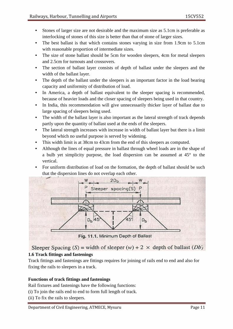
Fish platesFish plates are used in rail joints to maintain the continuity of the rails.Two types of fish plates are commonly used on Indian Railways for joining F.F. and
B.H. rails, each fish plate is 457 mm long and provided with four holes 32 mm at a spacing of114 mm c/c.
These are manufactured of steel and are so designed that they fit in between the headand foot of the rail.
Requirements of fish plates(i) They should hold the adjoining ends of rails in correct horizontal and vertical plane.(ii) They should allow free longitudinal movements of rails due to temperature variation.(iii) They should be able to resist all types of wear.(iv) They should allow easy renewal and replacement of rails in case of wear and damage.
Bearing plates
Railways, Harbour, Tunnelling and Airports 15CV552
Department of Civil Engineering, ATMECE, Mysuru Page 12
(iii) To maintain the correct alignment of the track.(iv) To provide proper expansion gap between rails.(v) To maintain the required tilt of rails.(vi) To set the points and crossings in proper position.
Fish platesFish plates are used in rail joints to maintain the continuity of the rails.Two types of fish plates are commonly used on Indian Railways for joining F.F. and
B.H. rails, each fish plate is 457 mm long and provided with four holes 32 mm at a spacing of114 mm c/c.
These are manufactured of steel and are so designed that they fit in between the headand foot of the rail.
Requirements of fish plates(i) They should hold the adjoining ends of rails in correct horizontal and vertical plane.(ii) They should allow free longitudinal movements of rails due to temperature variation.(iii) They should be able to resist all types of wear.(iv) They should allow easy renewal and replacement of rails in case of wear and damage.
Bearing plates
Railways, Harbour, Tunnelling and Airports 15CV552
Department of Civil Engineering, ATMECE, Mysuru Page 13
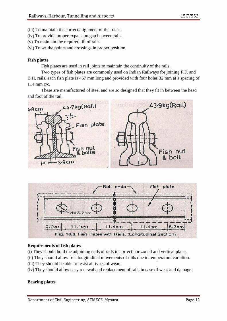
• Bearing plates are cast iron or steel plates placed in between the F.F rail and woodensleepers of a railway track.
• F.F. rails if fixed directly on wooden sleepers sink in the sleeper due to the heavyloads of trains and thus loosen the spikes.
• To overcome this difficulty bearing plates are used under F.F. rails to distribute theload over a wider area and bring the intensity of pressure within limit.
Advantages(i) They distribute the loads to wider area and prevent sinking of the rail to the sleeper.
(ii) They enable the spikes to remain tight and require less maintenance.(iii) Bearing plates prevent the widening of gauge on curves.(iv) Bearing plates increase the overall stability of the track.(v) They prevent the destruction of the sleeper due to rubbing action of the rail.
Disadvantages
i. When the bearing plates become loose due to settlement of ballast, moisture is likelyto enter between the sleepers and plates, causing sleepers to wear.
ii. When any spike is damaged and it is required to be redriven at another place, all otherspikes of the bearing plates have to be removed, which will reduce the holding powerof the spikes.
SpikesRequirements of a good spike
(i) It should be easy in fixing or removing from the sleepers.(ii) It should hold the rails and bearing plates in proper position.(iii) It should be cheap.(iv) It should require minimum maintenance.(v) It should not come out of the sleepers under vibrations.
Dog spikes: Dog spikes are the cheaper type of spikes which hold the rails at correct gaugeand can be easily fixed and removed. These are commonly used for holding F.F. rails. Fourdog spikes are used per sleeper, two on either side of the rail.
Railways, Harbour, Tunnelling and Airports 15CV552
Department of Civil Engineering, ATMECE, Mysuru Page 13
• Bearing plates are cast iron or steel plates placed in between the F.F rail and woodensleepers of a railway track.
• F.F. rails if fixed directly on wooden sleepers sink in the sleeper due to the heavyloads of trains and thus loosen the spikes.
• To overcome this difficulty bearing plates are used under F.F. rails to distribute theload over a wider area and bring the intensity of pressure within limit.
Advantages(i) They distribute the loads to wider area and prevent sinking of the rail to the sleeper.
(ii) They enable the spikes to remain tight and require less maintenance.(iii) Bearing plates prevent the widening of gauge on curves.(iv) Bearing plates increase the overall stability of the track.(v) They prevent the destruction of the sleeper due to rubbing action of the rail.
Disadvantages
i. When the bearing plates become loose due to settlement of ballast, moisture is likelyto enter between the sleepers and plates, causing sleepers to wear.
ii. When any spike is damaged and it is required to be redriven at another place, all otherspikes of the bearing plates have to be removed, which will reduce the holding powerof the spikes.
SpikesRequirements of a good spike
(i) It should be easy in fixing or removing from the sleepers.(ii) It should hold the rails and bearing plates in proper position.(iii) It should be cheap.(iv) It should require minimum maintenance.(v) It should not come out of the sleepers under vibrations.
Dog spikes: Dog spikes are the cheaper type of spikes which hold the rails at correct gaugeand can be easily fixed and removed. These are commonly used for holding F.F. rails. Fourdog spikes are used per sleeper, two on either side of the rail.
Railways, Harbour, Tunnelling and Airports 15CV552
Department of Civil Engineering, ATMECE, Mysuru Page 14
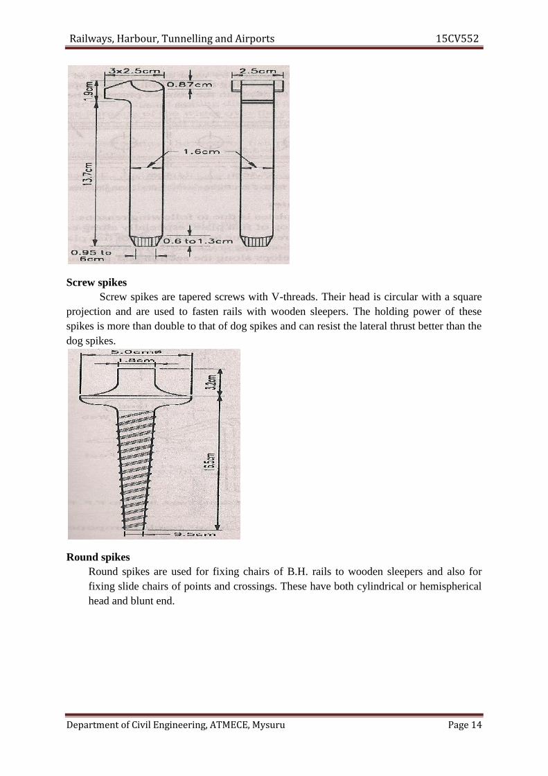
Screw spikesScrew spikes are tapered screws with V-threads. Their head is circular with a square
projection and are used to fasten rails with wooden sleepers. The holding power of thesespikes is more than double to that of dog spikes and can resist the lateral thrust better than thedog spikes.
Round spikesRound spikes are used for fixing chairs of B.H. rails to wooden sleepers and also forfixing slide chairs of points and crossings. These have both cylindrical or hemisphericalhead and blunt end.
Railways, Harbour, Tunnelling and Airports 15CV552
Department of Civil Engineering, ATMECE, Mysuru Page 15
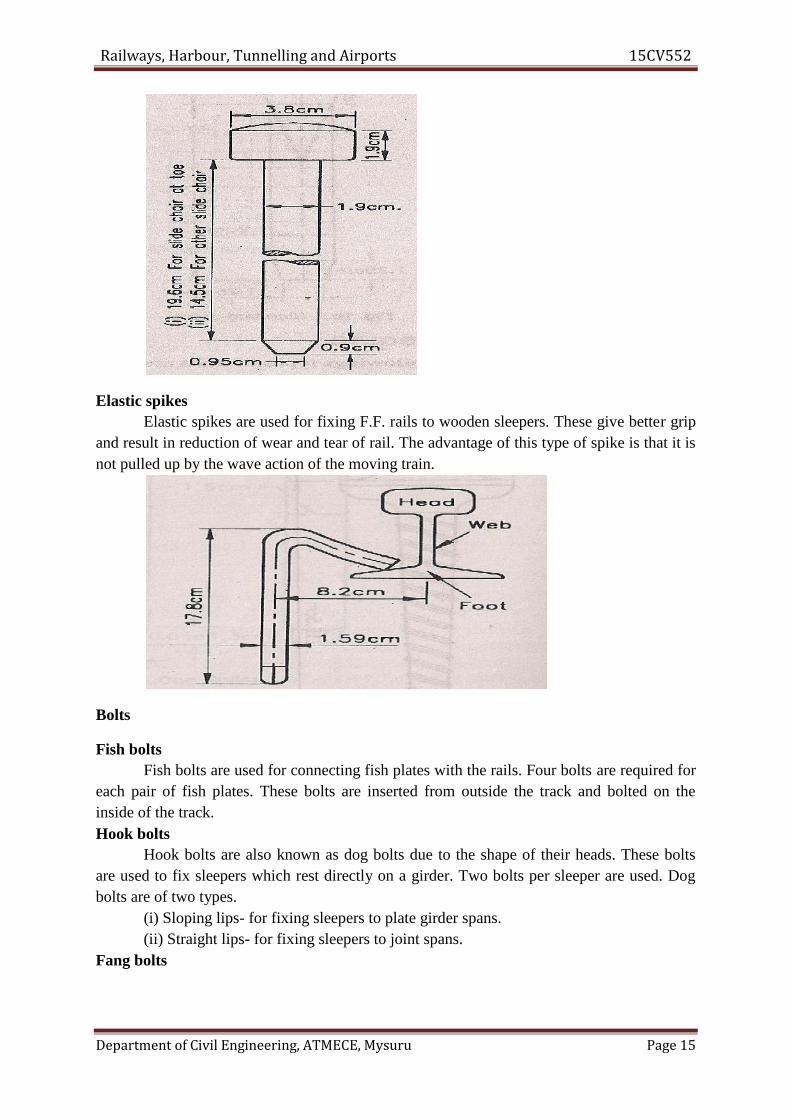
Elastic spikesElastic spikes are used for fixing F.F. rails to wooden sleepers. These give better grip
and result in reduction of wear and tear of rail. The advantage of this type of spike is that it isnot pulled up by the wave action of the moving train.
Bolts
Fish boltsFish bolts are used for connecting fish plates with the rails. Four bolts are required for
each pair of fish plates. These bolts are inserted from outside the track and bolted on theinside of the track.Hook bolts
Hook bolts are also known as dog bolts due to the shape of their heads. These boltsare used to fix sleepers which rest directly on a girder. Two bolts per sleeper are used. Dogbolts are of two types.
(i) Sloping lips- for fixing sleepers to plate girder spans.(ii) Straight lips- for fixing sleepers to joint spans.
Fang bolts
Railways, Harbour, Tunnelling and Airports 15CV552
Department of Civil Engineering, ATMECE, Mysuru Page 16
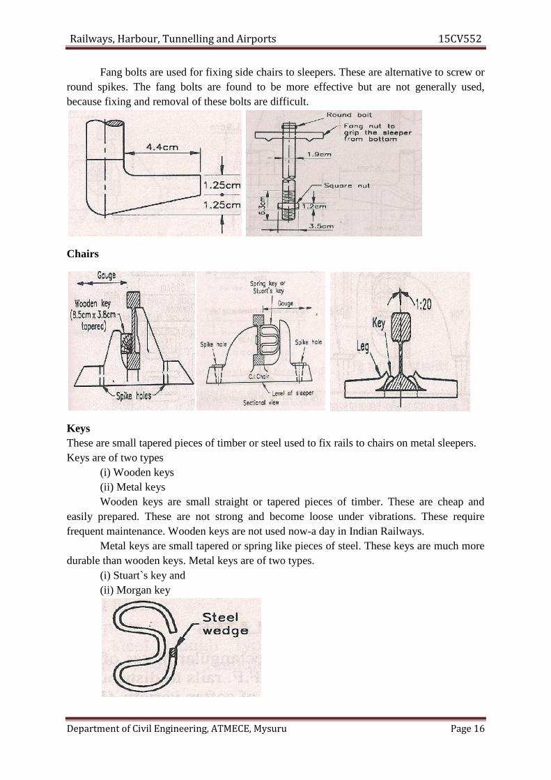
Fang bolts are used for fixing side chairs to sleepers. These are alternative to screw orround spikes. The fang bolts are found to be more effective but are not generally used,because fixing and removal of these bolts are difficult.
Chairs
KeysThese are small tapered pieces of timber or steel used to fix rails to chairs on metal sleepers.Keys are of two types
(i) Wooden keys(ii) Metal keysWooden keys are small straight or tapered pieces of timber. These are cheap and
easily prepared. These are not strong and become loose under vibrations. These requirefrequent maintenance. Wooden keys are not used now-a day in Indian Railways.
Metal keys are small tapered or spring like pieces of steel. These keys are much moredurable than wooden keys. Metal keys are of two types.
(i) Stuart`s key and(ii) Morgan key
Railways, Harbour, Tunnelling and Airports 15CV552
Department of Civil Engineering, ATMECE, Mysuru Page 16
Fang bolts are used for fixing side chairs to sleepers. These are alternative to screw orround spikes. The fang bolts are found to be more effective but are not generally used,because fixing and removal of these bolts are difficult.
Chairs
KeysThese are small tapered pieces of timber or steel used to fix rails to chairs on metal sleepers.Keys are of two types
(i) Wooden keys(ii) Metal keysWooden keys are small straight or tapered pieces of timber. These are cheap and
easily prepared. These are not strong and become loose under vibrations. These requirefrequent maintenance. Wooden keys are not used now-a day in Indian Railways.
Metal keys are small tapered or spring like pieces of steel. These keys are much moredurable than wooden keys. Metal keys are of two types.
(i) Stuart`s key and(ii) Morgan key
Railways, Harbour, Tunnelling and Airports 15CV552
Department of Civil Engineering, ATMECE, Mysuru Page 17
1.7 Track stress:The wheel loads: The static load due to wheel is transmitted to the point of contact of thewheel and the railDynamic effect of wheel loads: The dynamic effect is caused due to speed and hammerblows by the moving wheels.Hammer blow: Due to over balance of driving wheels of locomotive.The horizontal thrust: Due to nosing action of the locomotive.The pressure by the flanges of wheels on the sides of the rail: There is lateral pressure dueto flanges collision with the rails because the locomotive or train moves in zig-zag manner.Stresses due to irregularities in the track: When ballast or subgrade are not evenly laid,non-uniformity in the gauge and top of the rails are not in one level.Additional stresses on curves: Lateral bending due to rigid wheel base of the vehicle andnon-uniform distribution of pressure over outer and inner wheels.
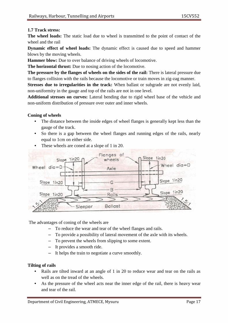
Coning of wheels• The distance between the inside edges of wheel flanges is generally kept less than the
gauge of the track.• So there is a gap between the wheel flanges and running edges of the rails, nearly
equal to 1cm on either side.• These wheels are coned at a slope of 1 in 20.
The advantages of coning of the wheels are– To reduce the wear and tear of the wheel flanges and rails.– To provide a possibility of lateral movement of the axle with its wheels.– To prevent the wheels from slipping to some extent.– It provides a smooth ride.– It helps the train to negotiate a curve smoothly.
Tilting of rails• Rails are tilted inward at an angle of 1 in 20 to reduce wear and tear on the rails as
well as on the tread of the wheels.• As the pressure of the wheel acts near the inner edge of the rail, there is heavy wear
and tear of the rail.
Railways, Harbour, Tunnelling and Airports 15CV552
Department of Civil Engineering, ATMECE, Mysuru Page 17
1.7 Track stress:The wheel loads: The static load due to wheel is transmitted to the point of contact of thewheel and the railDynamic effect of wheel loads: The dynamic effect is caused due to speed and hammerblows by the moving wheels.Hammer blow: Due to over balance of driving wheels of locomotive.The horizontal thrust: Due to nosing action of the locomotive.The pressure by the flanges of wheels on the sides of the rail: There is lateral pressure dueto flanges collision with the rails because the locomotive or train moves in zig-zag manner.Stresses due to irregularities in the track: When ballast or subgrade are not evenly laid,non-uniformity in the gauge and top of the rails are not in one level.Additional stresses on curves: Lateral bending due to rigid wheel base of the vehicle andnon-uniform distribution of pressure over outer and inner wheels.
Coning of wheels• The distance between the inside edges of wheel flanges is generally kept less than the
gauge of the track.• So there is a gap between the wheel flanges and running edges of the rails, nearly
equal to 1cm on either side.• These wheels are coned at a slope of 1 in 20.
The advantages of coning of the wheels are– To reduce the wear and tear of the wheel flanges and rails.– To provide a possibility of lateral movement of the axle with its wheels.– To prevent the wheels from slipping to some extent.– It provides a smooth ride.– It helps the train to negotiate a curve smoothly.
Tilting of rails• Rails are tilted inward at an angle of 1 in 20 to reduce wear and tear on the rails as
well as on the tread of the wheels.• As the pressure of the wheel acts near the inner edge of the rail, there is heavy wear
and tear of the rail.

Railways, Harbour, Tunnelling and Airports 15CV552
Department of Civil Engineering, ATMECE, Mysuru Page 18
• Lateral bending stresses are also created due to eccentric loading of rails.• To reduce the wear and tear as well as lateral stresses, rails are tilted at a slope of 1 in
20, which is also the slope of wheel cone.
Creep of rails• It is defines as the longitudinal movement of rails with respect to sleepers in a track.• Creep is common to all railway tracks, but varies in magnitude considerably, the rail
in some places moves by several centimetres in a month while in other location themovement of rails may be negligible.
• It is observed that the rails have tendency to move gradually in the direction ofdominant traffic.
• Indications of creep can be noticed from the following observations:– Closing of successive expansion spaces at rail joints in the direction of creep
and opening out of joints at the point from where creep starts.– Marks on flanges and webs of rails made by spike heads, by scraping or
scratching as the rail slide.Causes:
– Wave action.– Drag theory.– Starting, accelerating, slowing/stopping of train.– Expansion or contraction of rail.– Unbalanced traffic.– Alignment of track.– Grade of track.– Type of rails.– Poor maintenance of track components and ill design.
Remedies:– Pulling back the rails.– Provision of Anti-creepers.– Use of Steel Sleepers.
Wear on rails• Wear is one of the prominent defects of rails.• When the axle loads are abnormally heavy and the train moves with very fast speed
then the concentrated stresses exceed the elastic limit resulting in metal flow, on the
Railways, Harbour, Tunnelling and Airports 15CV552
Department of Civil Engineering, ATMECE, Mysuru Page 19
gap or joint the ends are battered and at the curves the occurrence of skidding,slipping and striking of wheel flanges with rails results in wear and tear of rails.
• Classification of wear– On the basis of location.– On the basis of position of wear on rails.
• On the basis of location– On sharp curves– On gradients– On approaches to stations, where brakes are frequently applied.– In tunnels– Coastal areas(sea breeze)– Weak foundations
On the basis of position of wear– Wear on the top or head of rail– Wear at the ends of rails– Wear on the sides of the head.
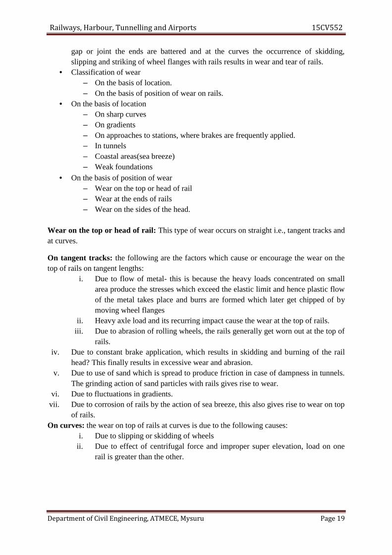
Wear on the top or head of rail: This type of wear occurs on straight i.e., tangent tracks andat curves.
On tangent tracks: the following are the factors which cause or encourage the wear on thetop of rails on tangent lengths:
i. Due to flow of metal- this is because the heavy loads concentrated on smallarea produce the stresses which exceed the elastic limit and hence plastic flowof the metal takes place and burrs are formed which later get chipped of bymoving wheel flanges
ii. Heavy axle load and its recurring impact cause the wear at the top of rails.iii. Due to abrasion of rolling wheels, the rails generally get worn out at the top of
rails.iv. Due to constant brake application, which results in skidding and burning of the rail
head? This finally results in excessive wear and abrasion.v. Due to use of sand which is spread to produce friction in case of dampness in tunnels.
The grinding action of sand particles with rails gives rise to wear.vi. Due to fluctuations in gradients.
vii. Due to corrosion of rails by the action of sea breeze, this also gives rise to wear on topof rails.
On curves: the wear on top of rails at curves is due to the following causes:i. Due to slipping or skidding of wheels
ii. Due to effect of centrifugal force and improper super elevation, load on onerail is greater than the other.
Railways, Harbour, Tunnelling and Airports 15CV552
Department of Civil Engineering, ATMECE, Mysuru Page 20
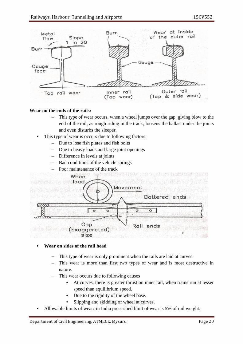
Wear on the ends of the rails:– This type of wear occurs, when a wheel jumps over the gap, giving blow to the
end of the rail, as rough riding in the track, loosens the ballast under the jointsand even disturbs the sleeper.
• This type of wear is occurs due to following factors:– Due to lose fish plates and fish bolts– Due to heavy loads and large joint openings– Difference in levels at joints– Bad conditions of the vehicle springs– Poor maintenance of the track
• Wear on sides of the rail head
– This type of wear is only prominent when the rails are laid at curves.– This wear is more than first two types of wear and is most destructive in
nature.– This wear occurs due to following causes
• At curves, there is greater thrust on inner rail, when trains run at lesserspeed than equilibrium speed.
• Due to the rigidity of the wheel base.• Slipping and skidding of wheel at curves.
• Allowable limits of wear: in India prescribed limit of wear is 5% of rail weight.
Railways, Harbour, Tunnelling and Airports 15CV552
Department of Civil Engineering, ATMECE, Mysuru Page 20
Wear on the ends of the rails:– This type of wear occurs, when a wheel jumps over the gap, giving blow to the
end of the rail, as rough riding in the track, loosens the ballast under the jointsand even disturbs the sleeper.
• This type of wear is occurs due to following factors:– Due to lose fish plates and fish bolts– Due to heavy loads and large joint openings– Difference in levels at joints– Bad conditions of the vehicle springs– Poor maintenance of the track
• Wear on sides of the rail head
– This type of wear is only prominent when the rails are laid at curves.– This wear is more than first two types of wear and is most destructive in
nature.– This wear occurs due to following causes
• At curves, there is greater thrust on inner rail, when trains run at lesserspeed than equilibrium speed.
• Due to the rigidity of the wheel base.• Slipping and skidding of wheel at curves.
• Allowable limits of wear: in India prescribed limit of wear is 5% of rail weight.
Railways, Harbour, Tunnelling and Airports 15CV552
Department of Civil Engineering, ATMECE, Mysuru Page 21
Wear Prevention
– Better maintenance of track– Reducing number of joints– Use of special alloy steel– Interchanging inner and outer rails– Regular maintenance of rail joints– Maintenance of correct gauge– Application of heavy mineral oil-corrosion– Lubricating gauge face– Using check rails in sharp curves
1.8 Route alignment surveys
1.8.1 Conventional method: In the manual method how we can get generate railwayalignment by the following various surveys which consume a huge time and money andsources too. In order to have a proper and satisfactory new route, various surveys are carriedout:1. Reconnaissance Survey2. Preliminary Survey3. Location Survey
Reconnaissance Survey: It is the first engineering survey. It is a rough and visualidentification about location and check map data to live location.
A reconnaissance survey can divided into two parts:1. Traffic survey2. Engineering survey
Traffic survey: This consists of collection of the information regarding the following: The general scenario of the location. Information of the local industries. The general information of agriculture, crop types and any mineral sources are there
or not. The probable scenario of traffic to divert or used by new railway alignment. General study of existing transportation facilities and which mode is mostly used. Planning forecasting of economic and social growth of area that would be covered by
this new railway line.
Engineering survey: Physical features of the country; The surface of the ground; Types of soil and its classification Streams and rivers, those which will cross the proposed railway line; Positions of valleys, mountains and rivers. Availability of materials and man power and transportation facilities of material for
use during construction.
Railways, Harbour, Tunnelling and Airports 15CV552
Department of Civil Engineering, ATMECE, Mysuru Page 22
Preliminary Survey:Object of preliminary survey To conduct the survey work along the alternative routes found out by reconnaissancesurvey and; To determine with greater accuracy the cost of the railway line along these alternativeroutes.
Importance of preliminary survey It decides the final route and recommends only one particular route in preference to otheralternative routes Thus, should be carried out with great precision as on it depends the alignment of the finalroute.
Location Survey:Object of location survey To carry out the detailed survey of the selected route to find whether it is economical andfeasible? From preliminary surveys data. It the centre-line of the alignment track to be laid. As soon as the location survey is completed, the construction work is started.
Work of location surveyIt is carried out in two stages:
1. Paper location The final route selected is put up on paper and details such as gradient, curves, contours,etc. are worked out; All the working drawings are prepared, even of minor structures such as signal cabins. After the paper location is over, the field work is started and the centre-line of the track isfixed.
2. Field location: The field location transfers paper location on the ground. It gives all the requirements of the construction engineer such as bench-marks, levels,measurements, etc. The centre-line pegs are driven at every 300 meters along the centre-line of the track. Every change of direction, the beginning and end of the curve and also the intersectingpoints are clearly marked. In addition to the fixing up of the centre-line of the track, the centre-lines of bridges,culverts, tunnels, station buildings, signal cabins, etc. should also be fixed.
1.8.2 Modern methods of designing of railway alignmentGIS study: This how we can generate various thematic maps for any particular area
Planning of proposed railway alignment with the help by generating thematic maps: Safety: The track should be aligned so as to ensure that goods and passengers aretransported with minimal chances of accidents and derailment. Aesthetic aspect: The railway line should be constructed to provide a memorable andpleasant railway journey to train passengers by keeping the track within beautiful naturalsurroundings.

Railways, Harbour, Tunnelling and Airports 15CV552
Department of Civil Engineering, ATMECE, Mysuru Page 23
Economy: The track should be as short and direct as possible with minimal construction,maintenance and operating costs from an engineering perspective. Linking of centres: A new railway line should connect and inter link important town centersand cities so as to provide the necessary transportation services.
In view of the above alignment requirements, minimal evaluation factors and constraints areidentified as follows: Slope Factor: The slope of terrain is considered very critical in railway routing as it
directly influences the construction and operating costs. The higher the slope, the higherthe costs and vice-versa
Soil Factor: Soils that are susceptible to erosion and unconsolidated materials cost moreto construct a railway line on. Poorly drained soils are also undesirable for railway lineconstruction. It is therefore comparatively cheaper to construct a railway on ground withsoil that is unconsolidated and well drained. Rocky grounds should be avoided as theyincrease construction costs due to heavy excavation of rocks.
Proximity to Rivers FactorRailways should be constructed as far away from rivers as possible because of the followingReasons: To avoid constructing many bridges that may arise because of the meandering of the rivers. Rivers have the propensity to flood and this could cause damage to the railway line. Rivers often change their course and this could cause rerouting of the railway which is avery expensive affair.
Important Towns and Cities constraintTown centres form important obligatory nodes and the track should pass through importanttown centres for economic, social and political reasons. Quarries and human habitats arefound in the neighbourhood of town centres and therefore construction materials and labourare easily available.Even though a town centre may neither be economically nor industrially active, socio-political considerations may still constrain the construction of a railway line through it.
Areas the Route must not pass through constraintThese are areas in which the railway track must be completely avoided since they result invery high construction and operation costs. They also pose a danger to the safety inoperations of the rail vehicles. Such undesirable areas include: Areas with ground slopes greater than 4.5%. Areas within 100m of the centrelines of rivers. Flood plains or swampy grounds. Areas within 50m of the centres of existing roads (to avoid accidents).
Multi-Criteria Evaluation: A MCE technique is a multi-criteria method which combinesdifferent data of different variable in to one indexed form and make fair decision with morealternatives in consistent and precise way. The main use of it is a rather than doing differentlycalculation for different parameter we can do it in to a one way with combination of differentvariables in to one indexed form and by MCE and AHP method.

Railways, Harbour, Tunnelling and Airports 15CV552
Department of Civil Engineering, ATMECE, Mysuru Page 24
The importance of network analysis in GIS: Networks are all around us. Roads, railways,cables, pipelines, streams, arteries, metro and etc.Networks are used to transport freight, people, goods and communication and water too, evennetwork of retail markets to home and from retail markets to sources, networks areeverywhere.
Network analysis enables you to solve problems, such as finding the most efficient travelroute, generating travel Directions, finding the closest facility, defining service areas basedon travel time, travel cost and traffic too.
What is network analysis arc GIS used for design of railway alignment? Finding the best route in order of consume less time and money through passing of variousstops. Finding the closest facility in order to minimize travel cost between incidents and multiplefacilities. Driving direction in order to generated closest facility and consumes less time path. Finding and origin and cost o-d matrix. On basis of all this thematic maps and generated data in network analysis we can generatean alignment which is best and accurate comparatively on conventional methods.
1.9 Geometric Design of TrackNecessity of geometric design of a railway trackThe need for proper geometric design of a track arises because of the followingconsiderations:
(a) To ensure the smooth and safe running of trains(b) To achieve maximum speeds(c) To carry heavy axle loads(d) To avoid accidents and derailments due to a defective permanent way(e) To ensure that the track requires least maintenance(f) For good aesthetics
Gradients:Gradients are provided to negotiate the rise or fall in the level of the railway track. A
rising gradient is one in which the track rises in the direction of movement of traffic and in adown or falling gradient the track loses elevation the direction of movement of traffic.A gradient is normally represented by the distance travelled for a rise or fall of one unit.Sometimes the gradient is indicated as per cent rise or fall. For example, if there is a rise of 1m in 400 m, the gradient is 1 in 400 or 0.25 per cent.
Gradients are provided to meet the following objectives:(a) To reach various stations at different elevations(b) To follow the natural contours of the ground to the extent possible(c) To reduce the cost of earthwork

Railways, Harbour, Tunnelling and Airports 15CV552
Department of Civil Engineering, ATMECE, Mysuru Page 25
The following types of gradients are used on the railways: (a) Ruling gradient (b) Pusher orhelper gradient (c) Momentum gradient (d) Gradients in station yards
Ruling Gradient: The ruling gradient is the steepest gradient that exists in a section. Itdetermines the maximum load that can be hauled by a locomotive on that section. Whiledeciding the ruling gradient of a section, it is not only the severity of the gradient, but also itslength as well as its position with respect to the gradients on both sides that have to be takeninto consideration. The power of the locomotive to be put into service on the track also playsan important role in taking this decision, as the locomotive should have adequate power tohaul the entire load over the ruling gradient at the maximum permissible speed.
In plain terrain: 1 in 150 to 1 in 250In hilly terrain: 1 in 100 to 1 in 150
Once a ruling gradient has been specified for a section, all other gradients provided in thatsection should be flatter than the ruling gradient after making due compensation forcurvature.
Pusher or Helper Gradient: In hilly areas, the rate of rise of the terrain becomes veryimportant when trying to reduce the length of the railway line and, therefore, sometimes,gradients steeper than the ruling gradient are provided to reduce the overall cost. In suchsituations, one locomotive is not adequate to pull the entire load, and an extra locomotive isrequired. When the gradient of the ensuing section is so steep as to necessitate the use of anextra engine for pushing the train, it is known as a pusher or helper gradient. A Pushergradient of 1 in 75, 1 in 100 with additional one engine is generally used.
Momentum Gradient: The momentum gradient is also steeper than the ruling gradient andcan be overcome by a train because of the momentum it gathers while running on the section.In valleys, a falling gradient is sometimes followed by a rising gradient. In such a situation, atrain coming down a falling gradient acquires good speed and momentum, which givesadditional kinetic energy to the train and allows it to negotiate gradients steeper than theruling gradient. In sections with momentum gradients there are no obstacles provided in theform of signals, etc., which may bring the train to a critical juncture.
Gradients in Station Yards: The gradients in station yards are quite flat due to the followingreasons:(a) It prevents standing vehicles from rolling and moving away from the yard due to thecombined effect of gravity and strong winds.(b) It reduces the additional resistive forces required to start a locomotive to the extentpossible.It may be mentioned here that generally, yards are not levelled completely and certain flatgradients are provided in order to ensure good drainage. The maximum gradient prescribed instation yards on Indian Railways is 1 in 400, while the recommended gradient is 1 in 1000.
Grade compensation on curves
Railways, Harbour, Tunnelling and Airports 15CV552
Department of Civil Engineering, ATMECE, Mysuru Page 26
• The ruling gradient is the maximum gradient on a particular section but if a curve lieson ruling gradient, the resistance due to gradient is increased by that due to curvatureand this further increases the resistance beyond the ruling gradient.
• In order to avoid resistances beyond the allowable limits, the gradients are reduced oncurves and this reduction in gradients is known as grade compensation for curve.
• In India, compensation for curvature is given at 0.04% per degree of curve for B.G,0.03% for M.G and 0.02% for N.G.
Radius or degree of the curve• Curves on the railway are generally circular i.e., each curve should have the same
radius on every portion of it.• The radius of curve is represented by the degree of curve.
Where R is the Radius of curve in metres• So for 1° curve R=1720m and for 2° curve R=860m.• Maximum degree of curvature for B.G= 10 °( min R=175m)• Maximum degree of curvature for M.G= 16 °( min R=109m)• Maximum degree of curvature for N.G= 40 °( min R=44m)
Super elevation or Cant• When a train moves round a curve, it is subjected to a centrifugal force acting
horizontally at the centre of gravity of each vehicle radially away from the centre ofthe curve. This increases the weight on the outer rail.
• To counteract the effect of centrifugal force, the level of the outer rail is raised abovethe inner rail by a certain amount to introduce the centripetal force.
• This raised elevation of outer rail above the inner rail at a horizontal curve is calledsuper elevation (e).
•Relationship between super elevation (e), gauge(G), speed(V) and radius of curve(R).W= weight of the moving vehicle in kgv= speed of vehicle in m/secV= speed of vehicle in kmphR= radius of curve in metresG= gauge of track in metresg= acceleration due to gravity in m/sec2
α= angle of inclinationS= length of inclined surface in metres.
• Centrifugal force, ----------------(1)
R
1720D
R2
360
30
D
gR
WvF
2
Railways, Harbour, Tunnelling and Airports 15CV552
Department of Civil Engineering, ATMECE, Mysuru Page 27
• Now resolving forces along the inclined surface we get,
F cos α= W sin α ----------------(2)
Cos α= G/S and sin α=e/S
Therefore,
• The above equation is known as equilibrium cant. When lateral forces and wheelloads are almost equal, the cant is said to be equilibrium. This equilibrium cant isprovided on the basis of average speed of the trains.
• It should be noted that the trains pass over the curve with different speeds, the superelevation provided for a speed of 90kmph would not suit any other speed.
• The question arises as to what speed, the super elevation should be provided for.
• In both cases, whether the speeds are higher or lower than the speed on which superelevation has been calculated, a certain type of in equilibrium will develop.
• Because the super elevation increases with the square of the speed, so at higherspeeds, the centrifugal force will not be counter balanced and will result inoverturning of vehicles, while at lower speeds the tilt of the vehicle towards the insidefor not having been completely counter balanced by the centrifugal force, may resultin derailment.
• This is due to the fact that the centre of gravity may fall outside the base of support.
Limits of super elevation• Super elevation should be provided in such a way that train as to
accommodate various trains running with different speeds from time to time.• Normally the maximum value of super elevation according railway board is
1/10th of gauge.• But recently, the following values of maximum super elevation have been
prescribed on Indian railways varying from 1/10th to 1/12th of the gauge.Cant deficiency
centimetreR
GVe
metresR
GVe
metresGgR
veTherefore
S
eW
S
G
gR
Wv
,27.1
,127
,,
2
2
2
2

Railways, Harbour, Tunnelling and Airports 15CV552
Department of Civil Engineering, ATMECE, Mysuru Page 28
– The equilibrium cant is provided on the basis of equilibrium speed of differenttrains. But this equilibrium cant or super elevation falls short of that requiredfor the high speed trains. This shortage of cant is called cant deficiency.
– Cant deficiency is the difference between the equilibrium cant necessary forthe maximum permissible speed on a curve and the actual cant provided.Cant deficiency = Equilibrium cant - Actual cant
• Cant deficiency is limited due to two reasons:– Higher cant deficiency gives rise to higher discomfort to passengers.– Higher cant deficiency means higher would be the balanced centrifugal forces
and hence extra pressure and lateral forces on outer rails. This will requirestrong track and fastenings for stability.
Negative super elevation:– When the main line is on a curve and has turnout of contrary flexure leading to
a branch line, the super elevation necessary for the average speed running overthe main line cannot be provided.
– BQ is the outer rail of the main line curve must be higher than inner rail AP or inother words, the point B should be higher than point A.
– For branch line, however AC should be higher than BD or the point A should behigher than points B.
– These two contradictory conditions cannot be met at the same time within onelayout.
– So instead of outer rail AC on branch line being higher, it is kept lower than theinner rail BD.
– In such cases, the branch line curve has negative super elevation and thereforespeeds on both tracks must be restricted, particularly on branch line.
Widening of Gauge on CurvesA vehicle normally assumes the central position on a straight track and the flanges of thewheels stay clear of the rails. The situation, however, changes on a curved track. As soon asthe vehicle moves onto a curve, the flange of the outside wheel of the leading axle continues

Railways, Harbour, Tunnelling and Airports 15CV552
Department of Civil Engineering, ATMECE, Mysuru Page 29
to travel in a straight line till it rubs against the rail. Due to the coning of wheels, the outsidewheel travels a longer distance compared to the inner wheel. This, however, becomesimpossible for the vehicle as a whole since the rigidity of the wheel base causes the trailingaxle to occupy a different position. In an effort to make up for the difference in the distancetravelled by the outer wheel and the inner wheel, the inside wheels slip backward and theouter wheels skid forward. A close study of the running of vehicles on curves indicates thatthe wear of flanges eases the passage of the vehicle round curves, as it has the effect ofincreasing the gauge. The widening of the gauge on a curve has, in fact, the same effect andtends to decrease the wear and tear on both the wheel and the track.
The stipulations laid down with regard to the gauge on straight tracks and curves on IndianRailways are given in Table 13.7.The widening of the gauge on curves can be calculated using the formula
Where B is the wheel base of the vehicle in metres, R is the radius of the curve in metres, L =0.02 (h 2 +Dh)1/2 is the lap of the flange in metres, h is the depth of flange below top of therail, and D is the diameter of the wheel of the vehicle.
1.10 Point and Crossing
Points and crossings are provided facilitates the change of railway vehicles from one track toanother. The tracks may be parallel, diverging, or converging to each other. Points andcrossings are necessary due to the inside flanges of wheels of railway vehicles and, thereforerequire special arrangement to navigate their way on the rails. The points or switches aid indiverting the vehicles and the crossings provide gaps in the rails so as to help the flangedwheels to roll over them. A complete set of points and crossings, along with lead rails, iscalled a turnout.

Railways, Harbour, Tunnelling and Airports 15CV552
Department of Civil Engineering, ATMECE, Mysuru Page 30
Important terms
The following terms are often used in the design of points and crossings.
Turnout It is an arrangement of points and crossings with lead rails by means of which therolling stock may be diverted from one track to another. Figure (a) shows the variousconstituents of a turnout. The details of these constituents are given in Table below. Table:Parts of a turnout
Name of the main assembly Various constituents of the assembly Set of switches A pair ofstock rails, a pair of tongue rails, a pair of heel blocks, several slide chairs, two or morestretcher bars, and a gauge tie plate Crossing A nose consisting of a point rail and splice rails,two wing rails, and two check rails Lead rails Four sets of lead rails
Direction of a turnout A turnout is designated as a right-hand or a left-hand turnoutdepending on whether it diverts the traffic to the right or to the left. In Fig. (a), the turnout isa right-hand turnout because it diverts the traffic towards the right side. Figure (b) shows aleft-hand turnout. The direction of a point (or turnout) is known as the facing direction if avehicle approaching the turnout or a point has to first face the thin end of the switch. Thedirection is trailing direction if the vehicle has to negotiate a switch in the trailing direction,that is, the vehicle first negotiates the crossing and then finally traverses on the switch fromits thick end to its thin end. Therefore, when standing at the toe of a switch, if one looks inthe direction of the crossing, it is called the facing direction and the opposite direction iscalled the trailing direction.
Fig. (a) Constituents of a turnout
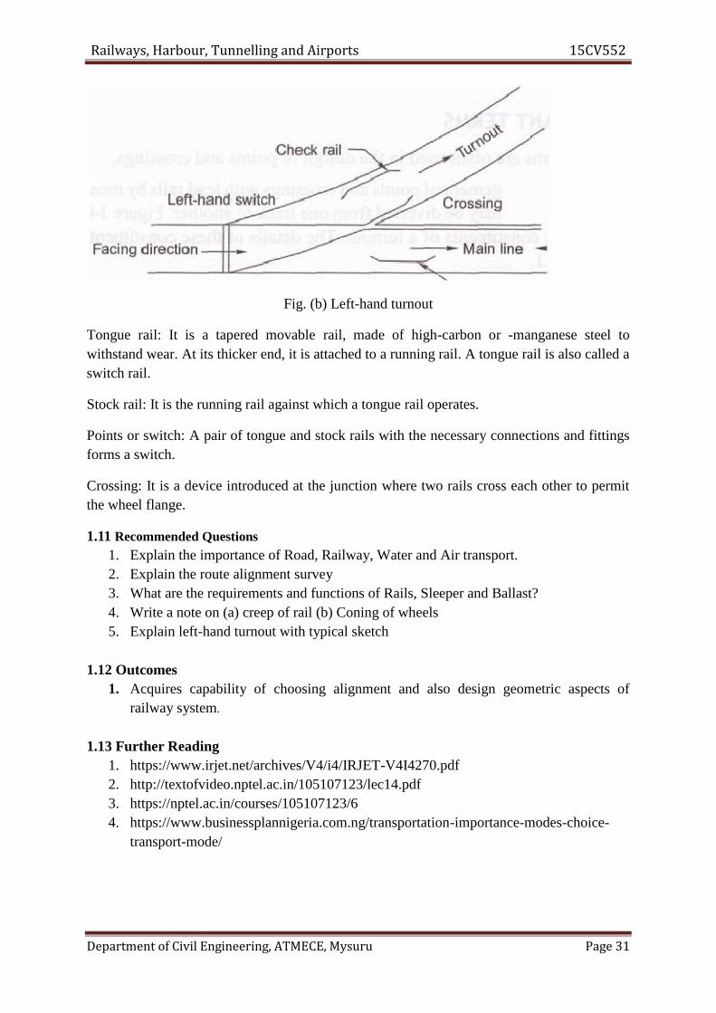
Railways, Harbour, Tunnelling and Airports 15CV552
Department of Civil Engineering, ATMECE, Mysuru Page 31
Fig. (b) Left-hand turnout
Tongue rail: It is a tapered movable rail, made of high-carbon or -manganese steel towithstand wear. At its thicker end, it is attached to a running rail. A tongue rail is also called aswitch rail.
Stock rail: It is the running rail against which a tongue rail operates.
Points or switch: A pair of tongue and stock rails with the necessary connections and fittingsforms a switch.
Crossing: It is a device introduced at the junction where two rails cross each other to permitthe wheel flange.
1.11 Recommended Questions1. Explain the importance of Road, Railway, Water and Air transport.2. Explain the route alignment survey3. What are the requirements and functions of Rails, Sleeper and Ballast?4. Write a note on (a) creep of rail (b) Coning of wheels5. Explain left-hand turnout with typical sketch
1.12 Outcomes1. Acquires capability of choosing alignment and also design geometric aspects of
railway system.
1.13 Further Reading1. https://www.irjet.net/archives/V4/i4/IRJET-V4I4270.pdf2. http://textofvideo.nptel.ac.in/105107123/lec14.pdf3. https://nptel.ac.in/courses/105107123/64. https://www.businessplannigeria.com.ng/transportation-importance-modes-choice-
transport-mode/
Railways, Harbour, Tunnelling and Airports 15CV552
Department of Civil Engineering, ATMECE, Mysuru Page 1
Module – 2Railway Construction and Maintenance
Structure2.0 Introduction2.1 Objectives2.2 Components of Railway Track Formation2.3 Methods of Construction2.4 Maintenance of Railway Track2.5 Modern methods of maintenance2.6 Railway Stations and Yards2.7 Types of Yards2.8 Passenger amenities2.9 Urban Transport2.10 Suburban Railways in Metro Cities2.11 Recommended questions2.12 Outcomes2.13 Further Reading
2.0 IntroductionMobility is a basic human need. From the times immemorial, everyone travels either
for food or leisure. A closely associated need is the transport of raw materials to amanufacturing unit or finished goods for consumption. Transportation fulfils these basicneeds of humanity. Transportation plays a major role in the development of the humancivilization. For instance, one could easily observe the strong correlation between theevolution of human settlement and the proximity of transport facilities. Also, there is a strongcorrelation between the quality of transport facilities and standard of living, because of whichsociety places a great expectation from transportation facilities. In other words, the solutionto transportation problems must be analytically based, economically sound, socially credible,environmentally sensitive, practically acceptable and sustainable. Alternatively, thetransportation solution should be safe, rapid, comfortable, convenient, economical, andecofriendly for both men and material.
2.1 Objectives1. Learn different types of structural components, engineering properties of the
materials, to calculate the material quantities required for construction2. Understand various aspects of geometric elements, points and crossings, significance
of maintenance of tracks.
2.2 Components of Railway Track Formation
Usual forms of cross-sections:
The naturally occurring soil is known as the subgrade and when it is prepared to receivethe ballast and track, it is called the formation.
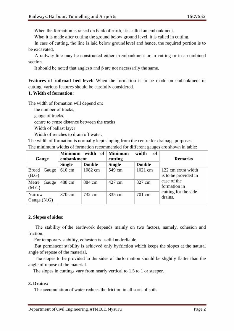
Railways, Harbour, Tunnelling and Airports 15CV552
Department of Civil Engineering, ATMECE, Mysuru Page 2
When the formation is raised on bank of earth, itis called an embankment. When it is made after cutting the ground below ground level, it is called in cutting. In case of cutting, the line is laid below ground level and hence, the required portion is tobe excavated. A railway line may be constructed either in embankment or in cutting or in a combinedsection. It should be noted that anglesα and β are not necessarily the same.
Features of railroad bed level: When the formation is to be made on embankment orcutting, various features should be carefully considered.1. Width of formation:
The width of formation will depend on: the number of tracks, gauge of tracks, centre to centre distance between the tracks Width of ballast layer Width of trenches to drain off water.The width of formation is normally kept sloping from the centre for drainage purposes.The minimum widths of formation recommended for different gauges are shown in table:
GaugeMinimum width ofembankment
Minimum width ofcutting Remarks
Single Double Single DoubleBroad Gauge(B.G)
610 cm 1082 cm 549 cm 1021 cm 122 cm extra widthis to be provided incase of theformation incutting for the sidedrains.
Metre Gauge(M.G)
488 cm 884 cm 427 cm 827 cm
NarrowGauge (N.G)
370 cm 732 cm 335 cm 701 cm
2. Slopes of sides:
The stability of the earthwork depends mainly on two factors, namely, cohesion andfriction. For temporary stability, cohesion is useful andreliable, But permanent stability is achieved only by friction which keeps the slopes at the naturalangle of repose of the material. The slopes to be provided to the sides of the formation should be slightly flatter than theangle of repose of the material.The slopes in cuttings vary from nearly vertical to 1.5 to 1 or steeper.
3. Drains: The accumulation of water reduces the friction in all sorts of soils.
Railways, Harbour, Tunnelling and Airports 15CV552
Department of Civil Engineering, ATMECE, Mysuru Page 3
In case of embankments, the rain water is easilydrained off. But in case of cuttings, drainsare to be provided. The side drains are constructed along the trackat a depth of about 1200 mm from the raillevel.The size of drains will depend on the quantity of water to be drained. Sometimes, pipes of stoneware or concrete are laid in a trench with open or half openjoints and covered with porous material.
Requirements of a Good Track Drainage SystemA good drainage system should satisfy the following requirements.Surface water should not percolate to track One of the basic requirements of a good trackdrainage system is that surface water from rains and adjacent areas should not percolate andseep into the formation of the track.Effective side drains The size of the side drains should be adequate with a proper slope, sothat they effectively carry all the surface water away.Longitudinal drains to be saucer-shaped The longitudinal drains provided between twotracks should preferably have a saucer-shaped cross section so that they can collect waterfrom both sides.Provision for clearing and inspection The drains provided for drainage should be such thatthey can be inspected and cleared periodically.Drain top to be below cess level Normally, the drain top should not be above the cess levelfor the effective drainage of the ballast bed.No erosion of banks The flow of water along the slope and across the track should not causeerosion of the banks or the slopes of the banks.Formation to be of good soil Ideally, the formation and subgrade should be made of apervious, coarse-textured soil. Such soils are more permeable, retain less capillary water, andrespond more favourably to a surface drainage system.Proper sub-surface drainage Arrangements should be made for a good subsurface drainagesystem to drain off the water being retained is the track. This is more relevant in the case ofdefective formations.Proper outfall Longitudinal drains should be designed so as to provide a proper outfall, fromwhere the water can eventually drain off.Special arrangements for waterlogged areas and other difficult situations A good trackdrainage system should have special arrangements for the drainage of waterlogged areas andfor all other related perennial problems.
Stabilization of track on poor soil:Sometimes it becomes unavoidable to lay tracks on a very poor (or undesirable) soil. In suchcases it becomes necessary to improve and strengthen the nature of soil by some suitablemethods. Under such circumstances, the following methods are used.
Layer of Moorum Cement Grouting Sand Piles
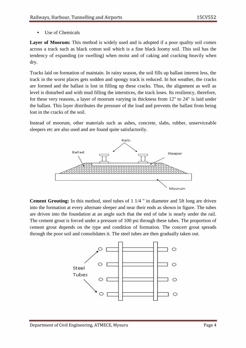
Railways, Harbour, Tunnelling and Airports 15CV552
Department of Civil Engineering, ATMECE, Mysuru Page 4
Use of Chemicals
Layer of Moorum: This method is widely used and is adopted if a poor quality soil comesacross a track such as black cotton soil which is a fine black loomy soil. This soil has thetendency of expanding (or swelling) when moist and of caking and cracking heavily whendry.
Tracks laid on formation of maintain. In rainy season, the soil fills up ballast interest less, thetrack in the worst places gets sodden and spongy track is reduced. In hot weather, the cracksare formed and the ballast is lost in filling up these cracks. Thus, the alignment as well aslevel is disturbed and with mud filling the interstices, the track loses. Its resiliency, therefore,for these very reasons, a layer of moorum varying in thickness from 12" to 24" is laid underthe ballast. This layer distributes the pressure of the load and prevents the ballast from beinglost in the cracks of the soil.
Instead of moorum, other materials such as ashes, concrete, slabs, rubber, unserviceablesleepers etc are also used and are found quite satisfactorily.
Cement Grouting: In this method, steel tubes of 1 1/4 " in diameter and 5ft long are driveninto the formation at every alternate sleeper and near their ends as shown in figure. The tubesare driven into the foundation at an angle such that the end of tube is nearly under the rail.The cement grout is forced under a pressure of 100 psi through these tubes. The proportion ofcement grout depends on the type and condition of formation. The concert grout spreadsthrough the poor soil and consolidates it. The steel tubes are then gradually taken out.

Railways, Harbour, Tunnelling and Airports 15CV552
Department of Civil Engineering, ATMECE, Mysuru Page 5
Sand Piles: This method of strengthening the track laid on poor is most widely used indevelopment countries like America. In this method, a vertical bore about 12" diameter ismade in the ground by driving a wooden pile. The wooden pile is then withdrawn and thespace is filled with sand and is well rammed. The sand piles are driven in the pattern asshown.
It is also arranged that cross sectional area of the sand piles is about 20% of the formationarea. Thus, the top section of the formation is covered with sand which makes the track stableon poor soil.
Use of Chemicals: In this method, chemicals are used in place of cement grout to consolidatethe soil. For example, silicate of soda followed by calcium chloride is effective for sandysoils containing less than 25% of silt and clay.
2.3 Methods of Construction1. Telescopic Method of Construction2. Trame line Method of Construction3. Mechanical Methods
1. TELESCOPIC METHOD OF CONSTRUCTIONIn this method of construction rails, sleepers, fastenings are unloaded from the material trainas closer to rail head as possible. The sleepers are carried by cart or by men along theadjoining service road and spread on the ballast. The rails are then carried on pairs to the endof last pair of connected rails and linked.
2. Trame Line Method of ConstructionThis method is used where tram carrier are installed for carrying earthwork or in rainy seasondue to difficulty in movement of cart. The basic difference between Telescopic and Trameline lies in the conveyance and spreading of sleepers.
3. Mechanical Methods

Railways, Harbour, Tunnelling and Airports 15CV552
Department of Civil Engineering, ATMECE, Mysuru Page 6
This method is extensively used in Britain and America by using special track layingmachine. There are two types of machines available1. In the first type track material carried by the material train and delivered at rail head andlay in the required position by means of projecting arm mounted on the truck nearest to therail head. The material train moves forward on the assembled track and operation repeated.
In the second method a long cantilevered arm projecting beyond fitted on the wagon. Apanel of assembled track consisting pair of rails with number of sleepers on the ballast layer.This panel is carried by special trolley running over the wagons of material train to the jibs. Itis lowered by the jib at the required position and connected to the previous panel. The trainmoves on and operation repeated.
2.4 Maintenance of Railway Track- Existing System of track Maintenance1. Manually2. Three tier system of maintenanceThe track should be maintained either by conventional system of track maintenance or bythree – tier system of track maintenance. In both the systems, track requires to be overhauledperiodically with the object of restoring it to best possible condition, consistent with itsmaintainability. Periodicity of overhauling depends on several factors, such as type of trackstructure, its age, and volume of traffic, rate of track deterioration, maximum permissiblespeed, system of traction, condition
Track Maintenance(A) Conventional system of track maintenance in this track is maintained manually(B) Three tier system of track maintenance
(1) 3- tier system of track maintenance shall be adopted on sections nominated formechanized maintenance. This shall consist of the following 3 tiers of maintenance-(i) On track machines(ii) Mobile maintenance units(iii) Sectional gangs
(2) Large track machines for track maintenance include tie tamping machines for plain trackand points and crossings, shoulder ballast cleaning machines, ballast-cleaning machines,Ballast regulating machines and dynamic track stabilizers. These machines shall be used asper the various instructions issued in Indian Railways Track Machines Manual.
These machines shall be deployed to carry out the following jobs.(a) Systematic tamping of plain track as well as points and crossings(b) Intermediate tamping of plain track as well as points and crossings(c) Shoulder ballast cleaning(d) Ballast profiling / redistribution(e) Track stabilization

Railways, Harbour, Tunnelling and Airports 15CV552
Department of Civil Engineering, ATMECE, Mysuru Page 7
(f) Periodical deep screening
(3) Mobile Maintenance Units-(a) The mobile maintenance units (MMU) shall consist of two groups-(i) MMU-I one for each PWI’s section(ii) MMU-II one for each sub division(b) The functions of MMU shall be as below:
3. Track Relaying Activities and existing system of Relaying Track relaying activitiesinvolves following activities:1. Plain track relaying viz.CTR, TRR and TSR2. Turnout relaying at present both these activities are performed both manually and bymachines.
2.5 Modern methods of maintenanceThe following are the main modern methods of track maintained:• Mechanised Maintenance or Mechanical Tamping• Measured Shovel Packing• Directed Track MaintenanceMechanised Maintenance• It makes use of track machines namely tampers for day to day track maintenance• This method is relatively more effective, economical, and efficient to cater the needs of highspeed and heavier axle loads.Methods of Mechanical Tamping• Off -Track Tamping• On- Track TampingOff-Track Tamping• Off-track tampers which are portable & can be taken off the track within a short period oftime are used.• They work in pairs from opposite sides of the sleepers diagonally under the rail seat toensure maximum consolidation of the ballast.• It requires no blocking of the trafficDemerits• Maintenance of tampers is difficult• High standard of maintenance cannot be achieved• Intensive supervision is needed• Transportation of tampers with power unit is difficultTypes of Off-Track Tampers1. Self-containedPercussion typeVibratory type2. Off-track tampers worked from a common power unitOn- Track Tamping

Railways, Harbour, Tunnelling and Airports 15CV552
Department of Civil Engineering, ATMECE, Mysuru Page 8
• On-track tampers which are self-propelled vehicles are used to tamp the sleepersautomatically through various controls provided in the operator's cabin• These are superior to off-track tampers in respect of control, efficiency, quality of work andretention of tamping.Automatic aligning, lifting, cross and longitudinal levelling and packing are simultaneouslypossibleTypes of On- Track Tampers• Light On- Track Tampers• Heavy On- Track Tampers
Measured Shovel Packing• In this method, the track defects like unevenness and voids are accurately measured, thetrack is lifted by means of jacks and measured quantities of small broken stone chippings areplaced under the sleeper, to bring the track to the predetermined level.Merits• No traffic block is needed for carrying out maintenance job• More output• Less materials are needed• Packing retentively of fish joined sleepers is more• Less tediousDemerits• Suitable for only flat bottom sleepers like wooden & concrete• Special sized stone chipping may not be readily available• Even for daily maintenance skilled labour is needed• Cannot be used for newly screened trackApplications of M.S.P• Maintenance of flat bottom wooden sleepers• Packing of joint wooden sleepers in metal sleeper track• Through packing of turnouts• Defogging of the hogged rail ends
Directed Track Maintenance (D.T.M)• It is a method to maintain the track as directed by day-to-day requirements but not asprescribed routine.• It is also called Track Maintenance System or TMSIt consists of 3 stages:• Proper identification of defects in track geometry by means of measuring and recordingdevices• Rectification of these defects only at indicated locations in order to maintain the track topredetermined standards• Checking the quality of work and output by the supervisor in charge of maintenanceObjectives of D.T.M• To maintain the track to a high standard of maintenance as per the prescribed tolerances

Railways, Harbour, Tunnelling and Airports 15CV552
Department of Civil Engineering, ATMECE, Mysuru Page 9
• To achieve economy in maintenance by avoiding unnecessary work involving men andmaterials
2.6 Railway Stations and YardsA railway station or a railroad station and often shortened to just station, is a railway
facility where trains regularly stop to load or unload passengers and/or freight
A railway station is that place on a railway line where traffic is booked and dealt withand where trains are given the authority to proceed forward. Sometimes only one of thesefunctions is carried out at a station and accordingly it is classified as a flag station or a blockstation. In the case of a flag station, there are arrangements for dealing with traffic but nonefor controlling the movement of the trains.
Requirements of a Passenger StationThe main requirements of a passenger yard are the following.(a) It should be possible to lower the signals for the reception of trains from differentdirections at the same time. This facility is particularly necessary at junction stations so thatall the trains what are to be connected with each other may be received at the same time.(b) Unless all trains are booked to stop at the station, it should be possible to run a trainthrough the station at a prescribed speed.(c) In the case of an engine changing station, an engine coming from or going to a shedshould cause minimum interference in the arrival and departure of trains.(d) An adequate number of platforms should be provided so that all trains can be dealt with atthe same time.(e) There should be convenient sidings where extra carriages can be stabled after having beendetached from trains or before their attachment to trains.(f) There should be provision of facilities for dealing with special traffic such as pilgrim andtourist traffic, parcels in wagon loads, livestock, and motor cars.(g) Stabling lines, washing lines, sick lines, etc., should be provided as per requirement.
Purpose / Requirements of a Railway StationA railway station is provided for one or more of the following purposes.(a) To entrain or detrain passengers(b) To load or unload goods or parcels(c) To control the movement of trains(d) To enable trains to cross each other in the case of a single-line section(e) To enable faster trains to overtake slower ones(f) To enable locomotives to refuel, whether it be diesel, water, or coal(g) To attach or detach coaches or wagons to trains(h) To collect food and water for passengers(i) To provide facilities for change of engines and crew/staff(j) To enable sorting out of wagons and bogies to form new trains(k) To provide facilities and give shelter to passengers in the case of emergencies such asfloods and accidents, which disrupt traffic
Railways, Harbour, Tunnelling and Airports 15CV552
Department of Civil Engineering, ATMECE, Mysuru Page 10
Selection of Site for a Railway StationThe following factors are considered when selecting a site for a railway station.Adequate land: There should be adequate land available for the station building, not only forthe proposed line but also for any future expansion. The proposed area should also be withoutany religious buildings.Level area with good drainage: The proposed site should preferably be on a fairly levelground with good drainage arrangements. It should be possible to provide the maximumpermissible gradient in the yard. In India, the maximum permissible gradient adopted is 1 in400, but a gradient of 1 in 1000 is desirable.Alignment: The station site should preferably have a straight alignment so that the varioussignals are clearly visible. The proximity of the station site to a curve presents a number ofoperational problems.Easy accessibility: The station site should be easily accessible. The site should be nearvillages and towns. Nearby villages should be connected to the station by means of approachroads for the convenience of passengers.Water supply arrangement: When selecting the site, it should be verified that adequatewater supply is available for passengers and operational needs.
Facilities Required at Railway StationsPassenger requirements: This includes waiting rooms and retiring rooms, refreshmentrooms and tea stalls, enquiry and reservation offices, bathrooms and toilets, drinking watersupply, platform and platform sheds, and approach roads.Traffic requirements: This includes goods sheds and platforms, station buildings, stationmaster’s office and other offices, signal and signal cabins, reception and departure lines andsidings, arrangements for dealing with broken down trains, and station equipment.Locomotive, carriage, and wagon requirements: This includes the locomotive shed,watering or fuelling facilities, turntable, inspection pits, ash pits, ashtrays, etc.Staff requirements: This includes rest houses for officers and staff, running rooms forguards and drivers, staff canteens, etc.
Classification of StationsStations can be classified on the basis of their operation as1. Block stations-Class A, Class B and Class C2. Non Block Stations-Class D stations or Flag stations3. Special class stations.Block Stations:The stations at the end the block sections are called Block stationsA class station: A class stations are normally provided on double-line sections. At suchstations a ‘line clear’ signal cannot be granted at the rear of a station unless the line on whicha train is to be received is clear and the facing points set and locked. No shunting can be doneafter line clear has been granted.

Railways, Harbour, Tunnelling and Airports 15CV552
Department of Civil Engineering, ATMECE, Mysuru Page 11
B class station: This is the most common type of station and is provided on single-line aswell as double-line sections. At a B class station, the line has to be clear up to an adequatedistance beyond the outer signal before ‘permission to approach’ can be given to a train. Theminimum signals required at a B class station are as follows.
C class station: The C class station is only a block hut where no booking of passengers isdone. It is basically provided to split a long block section so that the interval betweensuccessive trains is reduced. No train normally stops at these stations.

Railways, Harbour, Tunnelling and Airports 15CV552
Department of Civil Engineering, ATMECE, Mysuru Page 12
Non-block Stations or D Class Stations: D class or non-block stations are located betweentwo block stations and do not forms the boundary of any block section. No signals areprovided at D class stations.
Functional Classification of Stations: The layout of stations varies in size and importanceaccording to the type and volume of traffic handled and according to their locations withrespect to cities or industrial areas. Broadly speaking, the layouts required for passengerstations and their yards can be divided into the following categories for the purpose of study.(a) Halts(b) Flag stations(c) Roadside or crossing stations(d) Junction stations(e) Terminal stations
2.7 Types of YardsA yard is a system of tracks laid out to deal with the passenger as well as goods traffic beinghandled by the railways. This includes receipt and dispatch of trains apart from stabling,sorting, marshalling, and other such functions. Yards are normally classified into thefollowing categories.
Coaching yardThe main function of a coaching yard is to deal with the reception and dispatch of passengertrains. Depending upon the volume of traffic, this yard provides facilities such as wateringand fuelling of engines, washing of rakes, examination of coaches, charging of batteries, andtrans-shipment of passengers.
Goods yardA goods yard provides facilities for the reception, stabling, loading, unloading, and dispatchof goods wagons. Most goods yards deal with a full train load of wagons. No sorting,marshalling, and reforming is done at goods yards except in the case of ‘sick’ wagons or afew wagons booked for that particular station. Separate goods sidings are provided with theplatforms for the loading and unloading of the goods being handled at that station.
Marshalling yard

Railways, Harbour, Tunnelling and Airports 15CV552
Department of Civil Engineering, ATMECE, Mysuru Page 13
A goods yard which deals with the sorting of goods wagons to form new goods trains iscalled a marshalling yard. This is discussed in detail in Section 26.8.1.
Locomotive yardThis is the yard which houses the locomotive. Facilities for watering, fuelling, examininglocomotives, repairing, etc., are provided in this yard. The yard layout is designed dependingupon the number of locomotives required to be housed in the locomotive shed. The facilitiesare so arranged that a requisite number of locomotives are serviced simultaneously and arereadily available for hauling the trains. Such yards should have adequate space for storingfuel. The water supply should be adequate for washing the locomotives and servicing them.
Sick line yardWhenever a wagon or coach becomes defective, it is marked ‘sick’ and taken to sick lines.This yard deals with such sick wagons. Adequate facilities are provided for the repair ofcoaches and wagons, which include examination pits, crane arrangements, train examiner’soffice and workshop, etc. A good stock of spare parts should also be available with the TXR(train examiner) for repairing defective rolling stock.
2.8 Passenger amenities
1. Neat and clean entrance with facilities to get down from city transport2. Parking facility for two and four wheeler

Railways, Harbour, Tunnelling and Airports 15CV552
Department of Civil Engineering, ATMECE, Mysuru Page 14
3. Facility to buy ticket within reasonable time, display of the cost of ticket before a persondecides to buy
4. Display of train time-table and current running position5. Waiting hall6. Signage for easy identification and direction towards the facilities.7. Catering & vending stalls, adequate parking and circulating area, train indication board,
and public address system etc.8. Cyber Cafe, Food Plaza, At least one VIP lounge, Train coach indication system, CCTV
for announcement and security purpose, Coin operated ticket vending machine, Staticmobile charging facility.
9. Circulating area so as to ensure proper entry and exit of vehicles etc.10. A lighting tower for proper illumination, Improved modern, cost effective lighting
arrangements at the platforms, concourse etc.11. Improvement of booking and enquiry offices to give them a facelift, Lighting of booking
office, the queuing area in front of booking windows12. Renovated water booths, modern, Pay & Use toilets, Good Waiting and Retiring Rooms
with modern furniture.
2.9 Urban TransportThe basic objective of urban transport is to provide residences with access to activity such asworkplaces, schools, shopping centres, etc. The different forms of urban transport in use inmost cities of the world are the following.
Motorbuses: This is the most convenient form of transport and is used extensively inmetropolitan cities. These buses run mostly on diesel oil and their exhaust emissions have anadverse effect on the environment. Moreover, these buses, though very convenient fortransporting passengers, have very limited seating capacity.
Trolley Buses: These are buses that derive their energy through overhead electrictransmission. Trolley buses are superior to motorbuses as they do not pollute theenvironment. On the other hand, huge expenses are incurred in providing overhead tractionfor supplying power to these buses.
Tramways: Tramways require a track on which the trams can run and as such require theinfrastructure of a proper railway track. Their initial cost is quite high. They cause minimalair pollution; however, they contribute significantly to noise pollution. Tramways are almostobsolete now and are used only in some parts of the country such as in Kolkata.
Surface Railways: Surface railways are the cheapest and most extensively used form ofrailway service in the world. In such a system, the track is laid on a ground that has a suitableembankment or cutting, depending upon the topography of the area.
Underground Railways: In such a system, the railway line is constructed below the groundlevel. The requisite construction work is done mostly by the ‘cut and cover method’. The areais excavated in the shape of trenches and once the formation is ready, the track is laid, the
Railways, Harbour, Tunnelling and Airports 15CV552
Department of Civil Engineering, ATMECE, Mysuru Page 15
necessary overhead structures are provided, and finally the trenches are covered and theground is restored to its original state.
Elevated Railways: This type of railway is provided at an elevation above the ground level.The track is laid on a deck, which is supported by steel or RCC columns. The platforms andeven the station building are provided at an elevation for the convenience of passengers.The main advantage of elevated railways is that they do not require any separate land. Thereis no interference with road traffic as roads can be provided between the columns.
Monorail: The monorail is a form of elevated railway that is provided with only one rail onwhich trains run. The trains can be suspended on the monorail as in Montreal, Canada, or canbe mounted on pylons as in Tokyo, Japan. The monorail system is recommended only inexceptional cases where operating the conventional systems is difficult.
Tube Railways: In this rail system, the underground railways are generally provided at adepth of more than 25 m. The railway line is constructed in a tunnel that is circular or tubular.The main reason for taking the railway so deep into the ground is to avoid it interfering withthe water supply mains, sewerage system, telephone lines, gas lines, etc., which are normallylocated within 10 m of the natural ground.
2.10 Suburban Railways in Metro CitiesIntroductionThe term 'metropolitan city' is commonly used for major or important cities. Mostmetropolitan cities in India have grown in an unplanned and haphazard manner. Even inplaces where city master plans were available, the actual lands barely resemble what wasenvisaged in the plans. Delhi is one such example. The rapid growth in the population andeconomy of metropolitan cities has resulted in several social and economic problems. Theimbalance in the distribution of population and economic activity in these cities has led tolarge-scale intercity movement resulting in a serious transportation problem.
There are generally many limitations in the movement of people in these metropolitancities due to the following reasons.
The main problems of metropolitan cities are outlined below.(a) The traffic capacity of the roads in the major metropolitan cities has not kept pace with
the growing demands of traffic and this has resulted in severe congestion on the roads,particularly during peak hours and in central business districts.
(b) The average vehicular speed in these cities is about 20 to 30 km/hr and in some of thecongested parts of the core areas, speeds have been reduced to as low as 5 to 10 km/hr.A heavy, often unidirectional, peak load is required to be carried through certain routesduring specific hours every day. The design and capacity of these roads are unable tomeet the requirements of traffic and because of the several architectural structures thathave come upon their either side; the further widening of these roads is not possible.
(c) The number of road vehicles has increased considerably in the last few years, of theorder of 5 to 10% per year in the four metropolitan cities. In Delhi alone, the number ofregistered vehicles has multiplied in the last 10-year period. These cities keepexpanding in all directions at an alarming rate, placing additional demands on theexisting transport system.Environment pollution is widespread in metropolitan cities on account of the increase invehicular traffic and all round congestion. This has led to increased levels of noise anddust, increased vehicular emissions, and a loss of sunlight and daylight.

Railways, Harbour, Tunnelling and Airports 15CV552
Department of Civil Engineering, ATMECE, Mysuru Page 16
(e) The congestion on the roads in metropolitan cities has resulted in a large number ofaccidents. About 1.2 million road accidents take place annually in India, killing about85,000 people and injuring more than 0.1 million.
(f) There is a considerable wastage of time of a large number of people staying inmetropolitan cities on account of the slow movement of vehicles and the formation oflong queues on the roads.
A possible solution to these problems is to establish a proper mass transport system. Theexisting transport facilities must be suitably augmented and expanded to meet the growingtraffic demands. All types of road transport such as two wheelers, auto rickshaws, cars, andbuses have a maximum load capacity. Depending on the traffic density, one possible solutionwould be to strengthen and develop electric rail services, which, besides providing high-capacity transit facilities, also help substantially in energy conservation and environmentalpreservation. Further, from the point of view of relieving the roads of excess traffic and alsoof conserving energy, there is a need for urgent and deliberate measures that will discouragecommuters from using personal modes of transport and promote the use of publicconveyances instead.
Underground RailwaysIn such a system, the railway line is constructed below the ground level. The requisiteconstruction work is done mostly by the 'cut and cover method'. The area is excavated in theshape of trenches and once the formation is ready, the track is laid, the necessary overheadstructures are provided, and finally the trenches are covered and the ground is restored to itsoriginal state.
An underground railway system normally uses 'electric traction', as steam and dieseltractions produce smoke and lead to the pollution of the environment, which in this casebecomes particularly hazardous since these railways are underground. Proper arrangementsare also made for the drainage of underground railways as the low-lying areas in which theyare constructed are likely to get flooded during the rains. Such underground railways havebeen constructed in Kolkata and Delhi and in other countries around the world.
The main advantages and limitations of underground railways are as follows.
Advantages(a) Trains can run fast and unobstructed in an underground railway system as there are no
road crossings or other similar problems.(b) As the trains move at incredible speeds, underground railways can deal with a very high
concentration of human traffic.(c) There is no wastage of land and a large area of the city, which would have otherwise
been used for surface railways, remains available for other utilities.(d) Provides safety from aerial attacks, particularly during war.
Limitations(a) The underground railway system is a very costly arrangement and a heavy financial
backing is required. The cost may vary anywhere from Rs 30 million to 100 million perkm, depending upon the geographical features and other conditions.
(b) Special attention needs to be given to the drainage as well as proper ventilation ofunderground railways.
(c) During construction, the residents of the city are greatly inconvenienced as excavationwork is normally carried out throughout the city. The water supply, electricity supply,

Railways, Harbour, Tunnelling and Airports 15CV552
Department of Civil Engineering, ATMECE, Mysuru Page 17
and sewerage system of the city are also affected, as the diversion of many of theseservices is required during the constructional phase.
Cross section of an underground railwayAn underground railway may have either one of the following cross sections depending uponthe method used in its construction.
Cut and cover In this case, excavation is done by the cut and cover method. This methodaffects all public services such as water supply, sewerage mains and electric and telephonelines, which have to be diverted or suspended temporarily. The typical cross section of anunderground railway constructed using the cut and cover method is given in Fig
2.11 Recommended Questions1 Explain left hand and right hand turnout2 Explain classifications of stations3 Mention the purpose of railway station.
2.12Outcomes1 Acquires capability of choosing alignment and also design geometric aspects of
railway system.2 Suggest and estimate the material quantity required for laying a railway track and also
will be able to determine the hauling capacity of a locomotive.
2.13 Further Reading
1. http://www.indianrailways.gov.in/railwayboard/uploads/directorate/land_amen/downloads/Manual%20for%20WCS%20(Vol%201-%20Main%20Report).pdf
2. http://www.zits.pwr.wroc.pl/zwolski/source/CE12_Stations.pdf3. http://www.authorstream.com/Presentation/haroonalikhan3-1619293-stations-yards/4. http://www.mainline-project.eu/IMG/pdf/ml-d3.3-f-methods_for_switches__-
crossings_replacement.pdf5. http://www.vossloh.cogifer.com/media/downloads/pdfs/Vossloh_Cogifer_points_cros
sings_UK.pdf
Railways, Harbour, Tunnelling and Airports 15CV552
Department of Civil Engineering, ATMECE, Mysuru Page 1
Module – 3Harbour and Tunnel Engineering
Structure3.0 Introduction3.1 Objectives3.1 Classification of Harbours:3.2 Harbour components:3.3 Coastal Structures3.4 Wave action on Coastal Structures3.5 Size and shape of the tunnel3.6 Tunnelling in Soft Ground or Soft Rock3.7 Drainage of Tunnels3.8 Recommended questions3.9 Outcomes3.10 Further Reading
3.0 IntroductionHarbour:
It is partly enclosed area which provides safe and suitable accommodation forsupplies, refueling, repair, loading and unloading cargo.Port:
A port is a harbour where marine terminal facilities are provided.A port is a place which regularly provides accommodation for the transfer of cargo
and passengers to and from the ships.Port = Harbour + Storage Facility + Communication Facility + Other Terminal Facility.From above,It can be stated that a port includes a harbour i.e. every port is a harbour.
3.1 Objectives Apply design features of tunnels, harbours, dock and necessary navigational aids; also
expose them to various methods of tunneling and tunnel accessories.
Requirements of Good Harbour: It should be connected with roadway and railway. Surrounding land should be fertile and densely populated. Ship channels must have sufficient depth for draft or vessel. Breakwaters must be provided to protect against destructive wave action. The bottom should furnished secure anchorage to hold ships against the wind
force. Numbers of quay, piers and wharfs should be sufficient for loading and
unloading cargo. It should have facilities like fuel, repair and etc. for ships. Harbour area should be sufficiently large.
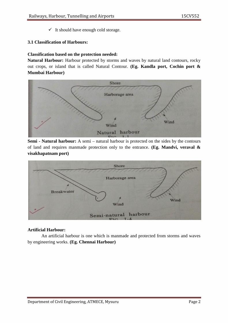
Railways, Harbour, Tunnelling and Airports 15CV552
Department of Civil Engineering, ATMECE, Mysuru Page 2
It should have enough cold storage.
3.1 Classification of Harbours:
Classification based on the protection needed:Natural Harbour: Harbour protected by storms and waves by natural land contours, rockyout crops, or island that is called Natural Contour. (Eg. Kandla port, Cochin port &Mumbai Harbour)
Semi - Natural harbour: A semi – natural harbour is protected on the sides by the contoursof land and requires manmade protection only to the entrance. (Eg. Mandvi, veraval &visakhapatnam port)
Artificial Harbour:An artificial harbour is one which is manmade and protected from storms and waves
by engineering works. (Eg. Chennai Harbour)

Railways, Harbour, Tunnelling and Airports 15CV552
Department of Civil Engineering, ATMECE, Mysuru Page 3
Classification based on utility:
Commercial Harbour: It is an harbour in which docks are provided with necessary facilitiesfor loading and unloading of cargo. (Eg. Chennai Harbour)
Refuge Harbour: These are used as a heaven for ships in a storm or it may be part of acommercial harbour. (Eg. Chennai Harbour & Visakhapatnam Harbour)
Military Harbour: It is a naval base for the purpose of accommodating naval ships orvessels and it serves as a supply depot. (Eg. Mumbai Harbour & Cochin Harbour)
Fishing Harbour: These harbours have facilities for departure and arrival of fishing ships.They have also necessary arrangement to catch fish.
Marina harbours: Marina is a harbour providing facilities of fuel, food, showers washingmachines, telephones etc. for small boat owners, having temporary or permanent berths.
Classification based on location:Canal harbour: The harbour located along the canals for sea navigations and inland isknown as canal harbour. It is found that the maintenance dredging of canal harbour basins isgenerally negligible.
Lake harbour: The harbour constructed along the shore of lake is known as lake harbour. Ifthe lake is large, then the conditions are similar to those in ocean except that tidal action doesnot occur.
River harbour: The harbour constructed along the banks of river is known as river harbour.Rivers create the main transportation route to join the hinterland and the sea.
Sea or Ocean harbour: The harbour located on the coast of sea or an ocean is called the seaharbour. They are intended for sea going vessels.
Classification of Ports:
Ocean Port: This is a port intended for large ocean going ships.
River Port: River port is located on the banks of the river inside the land.

Railways, Harbour, Tunnelling and Airports 15CV552
Department of Civil Engineering, ATMECE, Mysuru Page 4
Entry Port: This is location where foreign citizens and goods are cleared through customhouse.
Free Port: This is an isolated and enclosed area within which goods may be landed, stored,mixed, repacked, manufactured and reshipped without payment of duties.
Site Selection for Harbour:Great care has to be exercised at the time of making selection of site for a harbour.
The guiding factors which play a great role in choice of site for a harbour are as follows:
Availability of cheap land and construction material; Transport and communication facilities;
Natural protection from winds and waves; Industrial development of the locality;
Sea – bed, subsoil and foundation conditions; Traffic potentiality of harbour; Availability of electrical energy and fresh water;
Favorable marine conditions; Defense and strategic aspects etc.
3.2 Harbour components:
Entrance Channel Break Water Turning Basin Shelter Basin Pier Wharf

Railways, Harbour, Tunnelling and Airports 15CV552
Department of Civil Engineering, ATMECE, Mysuru Page 5
Quay Dry Dock Wet Dock Jetty
Entrance channel: Water area from which ships enter in the harbour and it should havesufficient width, 100 for small harbour, 100 to 160m for medium and 160 to 260m for largeharbour.
Break water: A protective barrier made up of Concrete or Course Rubble Masonryconstructed from shore towards the sea to enclose harbour .
Turning basin: It is water area which is required for maneuvering the ship after entering tothe harbour and it is large enough to permit free turning.
Shelter basin: It is area protected by shore and breakwater.
Pier: It is a solid platform at which berthing of ships on both the sides are possible.
Wharf: It is a docking platform constructed parallel to shoreline providing berthing facilityon one side only.
Quay: It is also dock parallel to the shore which is solid structure providing berthing on oneside and retaining the earth on the other.
Dry dock: It is a chamber provided for maintenance, repairs and construction of ships. Itincludes walls, floor and gate.
Wet dock: Due to variation in tidal level, an enclosed basin is provided where in number ofships can be berthed. It has an entrance which is controlled by a lock gate.
Jetty: It is a solid platform constructed perpendicular to the shoreline for berthing of ships.
Quay: It is also dock parallel to the shore which is solid structure providing berthing on oneside and retaining the earth on the other.
Dry dock: It is a chamber provided for maintenance, repairs and construction of ships. Itincludes walls, floor and gate.
3.3 Coastal Structures3.3.1 Breakwaters
The protective barrier constructed to enclose harbours and to keep the harbour watersundisturbed by the effect of heavy and strong seas are called breakwatersTypes of Breakwaters
1. Vertical wall breakwater2. Mound breakwater3. Mound with super structure or Composite breakwater
Vertical wall breakwater:

Railways, Harbour, Tunnelling and Airports 15CV552
Department of Civil Engineering, ATMECE, Mysuru Page 6
The construction of vertical wall break is found advantageous under the following conditions.• The depth of water is sufficiently large to prevent the breaking of waves. The depth of
water should be twice the height of the greatest storm wave.• Sea bed is resistant to erosion.• Foundations are not subjected to uneven settlement.
If the sea bed is not resistant to erosion, in that case concrete block apron may be providedfor protection. Also the load bearing characteristics of sea bed can be improved in variousways. If the top strata of the bed contain materials like soft clay, silt or fine sand, then thebest way is to remove these strata by trenching with a dredger.
Advantageous of vertical wall breakwater:• They need comparatively less construction materials.• They have no danger of unequal settlement as in the case of mound breakwater
Disadvantageous of vertical wall breakwater:• They need special care and costly methods of construction.• They need much height of wall under water, resulting in more cost.
Mound breakwaters:This is the simplest type of breakwater and constructed by dumping of rubbles, stones intothe sea till the mound emerges out of the water. The rubble mound breakwater comparativelyis safe.The looseness of the elements permits them to settle without damage. In this way theyprovide a broad base. This helps in distributing the load on a larger area reducing the unitload on the area.The quantity of rubble depends upon the depth, rise of tides and waves and exposure. Arubble mound breakwater consists of a central portion known as core and protective layersare known as armour.Advantageous of Mound breakwater:
• No special equipments are required for construction.• Unskilled labours can be employed.• Inspection is simple and easy.• Large size rubbles can be used without dressing.• It can be constructed on any type of foundation.• Construction is porous, hence no possibility of uplift.
Disadvantageous of Mound breakwater:• It requires huge quantity of materials• Initial cost is higher.• Requires regular maintenance.• Occupy large area of basin.
Mound with super structure or Composite breakwater:This breakwater has a rubble base over which a vertical wall type breakwater is
constructed. This is a combination of the mound and vertical wall type breakwater. This isrecommended in locations where the depth of water is great and the foundation is of weak
Railways, Harbour, Tunnelling and Airports 15CV552
Department of Civil Engineering, ATMECE, Mysuru Page 7
material. When the depth of water exceeds 30 m, the composite type of breakwater isadopted.Mound construction:Material size and arrangements:
Mounds are found in assorted layers, the smaller size material deposited at the baseand the larger at the top and sides, especially between high and low water levels.Method of construction:
Mound construction can be carried out by any of the following methods• Barge method• Staging method• Low level method
Barge method:Special barges having flat bottoms and hoppers with vertical sides and doors at the
bottom opening outwards are used for this purpose. The hoppers are loaded with rubbles andthe barge is adjusted and aligned in position along the line of construction and the rubble isdischarged in the sea by opening the doors of the hopper.Advantages:
• The main advantage of this method is that it deposits the material over a large areauniformly and simultaneously.
Disadvantages:• This method is not economical• The progress of the work depends on the weather conditions• If the rubble is not deposited properly, it may lead to the creation of irregular currents
Staging method:In this method a series of piles are driven in the water at a regular internal of 4.5 m to
6.0 m and connected by longitudinal struts, braces and runners forming a number of paralleltracks for tipping wagons to move on rails. These tracks are well above the high sea levelspaced at about 8 to 10 m apart.
The material is hauled on this staging and is tipped at ends and sides. As work in onesection is completed, the staging is removed and re-erected in a forward position to continuethe work. For withdrawing the staging piles from areas where the mound has been completeda very heavy and powerful tackle arrangement is required.Advantages:
• The degree of safety is very high in this method. Hence the execution of work can becarried out with confidence.
• Same staging materials except piles can be used several times, resulting in economy.• It provides a stable working base for the operations. Hence the work may be
uninterrupted even during stormy weather.Disadvantages:
• The timber staging may be damaged during storms• If the proper and sufficient precautions are not taken, timber is likely to be damaged
by marine insects.

Railways, Harbour, Tunnelling and Airports 15CV552
Department of Civil Engineering, ATMECE, Mysuru Page 8
• It takes a longer time for the rubble stone to form a flat slope in winter seasons.
Low level method:In this method the mound is formed in a length from the sea shore up to a sufficient
height at a time (i.e. above high sea level). Over this mound length the tracks are laid forrunning the tipping wagons as the solid breakwater structure advances. In this method multitrack section is not possible at a time.Advantages:
• The mound is consolidated during its construction itself by traffic of loaded wagons.• It saves cost of staging.
Disadvantages:• During heavy storms the work is interrupted.• The progress of work in this method is very low.• Working area is limited as the work only can be done when the bank is ready.• The lines are constantly disrupted by sea. They have to be raised very often resulting
in delay and heavy expenditure.
Tetrapod:
In coastal engineering, a tetrapod is a tetrahedral concrete structure used as armour
unit on breakwaters. A tetrapod's shape is designed to dissipate the force of incoming waves
by allowing water to flow around rather than against it, and to reduce displacement by
allowing a random distribution of tetrapods to interlock.Earlier barrier material used in breakwaters, such as boulders and conventional concreteblocks, tended to become dislodged over time by the force of the ocean constantly crashingagainst them.
Dolos:A dolos is a concrete block in a complex geometric shape weighing up to 20 tons, used ingreat numbers to protect harbour walls from the erosive force of ocean waves.
They are used to protect harbour walls, breakwaters and shore earthworks. They are also used
to trap sea-sand to prevent erosion.They work by dissipating, rather than blocking, the energy of waves. Their design deflectsmost wave action energy to the side, making them more difficult to dislodge than objects of asimilar weight presenting a flat surface. Though they are placed into position on top of eachother by cranes, over time they tend to get further entangled as the waves shift them. Theirdesign ensures that they form an interlocking but porous wall. However, they are notindestructible. Under extreme storm conditions they will hammer one another and bepounded into rubble
3.3.2 WharvesA wall constructed along a shore or bank to berth vessels for loading and unloading
cargo is known as a wharf.Uses of wharves:
Railways, Harbour, Tunnelling and Airports 15CV552
Department of Civil Engineering, ATMECE, Mysuru Page 9
• It is a platform parallel to the shoreline and provides berth on side of it.• It provides facilities like loading, unloading and storage of cargo.• It provides terminal facilities with link to rail or road transportation.
Factors affecting the design of wharves:• Adequate provision for berthing of the ship.• Adequate provision for handling and storage of cargo.• Adequate terminal facilities for rail and road transportation.
3.3.3 Quays:These walls are constructed to retain and protect the filling on the shore. These walls
are designed as retaining walls.Factors affecting the design of quay walls:
• Character or nature of the foundation.• Pressure of water on the back side of wall.• Earth pressure on the back of the wall.• Effect of buoyancy for the portion of the wall submerged.• Weight of the wall itself.• Live load of vehicles passing on the platform at the rear.• Dead load of goods stored on the platform.• Force of impact of vessels etc.
Types of quay walls:Gravity type quay walls:
These types of walls have to be founded under water and constructed in water andraised mounds above water by masonry construction or large concrete blocks.Dwarf quay wall:
These walls are founded and built on piles. These walls are economical for river portsand ports having moderate traffic.
The driest and most durable materials such as a slag, granite, rubbles etc. should beput at the back of the quay walls to minimise the pressure caused by back filling.
3.3.4 Piers:The structures built right angle to the sea shore or a river bank are known as piers.In the sea, the piers are constructed at places where the sea is not deep enough and the naturalharbour is not convenient for allowing the ships to berth adjacent to the shore.In many cases piers are constructed of piles, columns and braced leaving good space for theocean current to flow without causing any obstruction.
Design of pier:• The length of the pier should be sufficient to accommodate the longest ship likely to
visit the harbour.• Pier should be of sufficient width to allow easy unloading of cargo without any due
delay.

Railways, Harbour, Tunnelling and Airports 15CV552
Department of Civil Engineering, ATMECE, Mysuru Page 10
• The live loads for the design of a pier depend upon the nature of anticipated cargoand shipping.
• The impact effect of ship also is taken into consideration.
3.3.5 Pier head:It is a structure constructed at the tip of the breakwater near the harbour entrance. It
should be easily recognisable as it serves the purpose of an entrance mark and it should beprovided with strong light.
3.3.6 Jetties:A jetty is defined as a narrow structure projecting from the shore into water with
berths on one or both sides and sometimes at the end also.These are structures in the form of piled projections. They are built from the shore to
the deep water. Jetties are exposed to severe wave action and their structural design is similarto that of breakwater.
Uses of jetty:• It provides berth to the ships.• It is used for handling inflammable materials like petrol, diesel, kerosene and crude
oil
Construction of jetties:The jetties should be constructed depending upon the natural conditions and features
of the entrance channel.The provision of jetties may either be made in the initial stage of layout of harbour or
they may be constructed at a later stage to provide additional berthing accommodation.The form of a jetty may be as curved, converging or diverging.
Difference between wharf and jetty:• The wharf is a berth parallel to the shore, where as a jetty is perpendicular to the shore
or breakwater.• The wharf has berth on one side only as it has a back fill of earth. A jetty may have
berths on two faces or at the end also.3.3.7 DophinsThey are the marine structures located at the entrance of the locked or alongside a pier or awharf.Uses:- To absorb the impact force of the ships To provide mooring facilities i.e. for tying up ships
Types:-(A) Breasting Type
Provided in front of the sea face of the pier or wharf. Designed to take the impact of ship while docking and are equipped with fenders
(B) Mooring Type Located behind the seaward force of the berth
Railways, Harbour, Tunnelling and Airports 15CV552
Department of Civil Engineering, ATMECE, Mysuru Page 11
They are provided with mooring posts and with capstans where heavy lines are to behandled
Smaller than breasting dolphins
3.3.8 Fenders:A fender is a form of a cushion is provided on a jetty face for ships to come in
contact. The fender can be made of different materials in various forms It absorbs the impact of ship and protect them from damage
Types of Fenders:-(A) Wooden Fender
Simplest form of wooden fender are in the form of horizontal wooden member. They absorb energy because of deflection when struck by a ship
(B) Rubber Fenders The simplest form of rubber fenders are rubber tires hung over the side of the dock. Rubber fenders are supported by wire rope attached to eye bolt set in the concrete
dock wall
3.3.9 Moorings:The device used to anchor or attach a vessel in a harbour is known as moorings.It is not necessary for every harbour to have berthing facilities for the vessels, but it isabsolutely necessary to have some moorings where the vessels can come close to the harbourA vessel in distress may need shelter into the harbour even though it may not have anybusiness in the harbour. In such situation also moorings are required.
3.3.10 Wet docks:Docks are required for berthing of ships or vessels to facilitate the loading and
unloading of passengers and cargo are called as wet docks. Sometimes wet docks are calledor known as harbour docks.
Harbours are likely to be affected by tides, which may cause changes in the waterlevel. Where tidal ranges are very high and large, docks are formed by enclosures. The waterlevel in these enclosures should be maintained at constant level by providing locks and gates.Advantages of wet dock:
• Uniform water level can be maintained easily, which is essential and convenient forhandling cargo. The maintenance of water level increases the commercial activities ofthe port.
• It prevents the necessity of constant attention to the alteration of undulated bed of thearea or mooring.
• It prevents the rubbing of the sides of the ships against quay walls due to the tidaleffect.
• The effect of storm in the outer sea and harbour does not obstruct the dock enclosure.
Disadvantages of wet dock:

Railways, Harbour, Tunnelling and Airports 15CV552
Department of Civil Engineering, ATMECE, Mysuru Page 12
• For wet docks costly arrangements for locks and lock gates have to be provided. Thusthe wet docks are costly. This is their only disadvantages.
Shape of dock and basins:The shape of dock and basins should be straight to facilitate the ships to stand along
them as curved shape is not convenient for ships to stand along side.1. Rectangular shape: The length and breadth should be adjusted in such a way as to
give maximum quayage.2. Diamond shape: For the same perpendicular distance between long sides, the long
side could be extended conveniently.3. Inclined quay: It consists of a number of projecting quay into the dock or basin.
3.3.11 Dry or repair docks:In every harbour, some sort of repairs facilitates are desirable. The repair docks are
necessary for carrying out repairs, cleaning and painting bottoms of the ships. Thus this docksand docking arrangements should be such as to expose the ships exterior fully and keep it outof water during the process of repair or renovation.
Docks used for repairs of ships or vessels are known as dry docks.Classification of repair docks:
1. Graving or dry docks2. Floating dry docks3. Marine railway dock
Dry or Graving dock:A dry dock is also known as graving dock. It is a long excavated chamber, having side
walls, a semi circular end wall and a floor. The open end of the chamber is provided with agate and acts as the entrance to the dock.
The main principle of operating a dry dock is to admit a vessel into the chamber, closethe gate and pump out the water.Size of the dock:
The size of the dock depends upon the size of the largest ship likely to visit the drydock. The size of dry docks to handle the modern ships should have a length of 300 m withan entrance width of 25 m to 30 m. The ratio of length to breadth is about 9.5 to 1.
Floating dry docks:It may be defined as a floating vessel, which can lift a ship out of water and retain it
above water by means of its own buoyancy.It is a hallow structure made of steel or R.C.C consisting of two walls and a floor with
the ends open. To receive a vessel or ship for repair, the structure or floating dock is sunk tothe required depth by filling water known as ballasting in its interior chambers and the vesselis then floated into position and berthed.
The dock is raised bodily with the berthed vessel by un ballasting the chambers bypumping out the water.
Railways, Harbour, Tunnelling and Airports 15CV552
Department of Civil Engineering, ATMECE, Mysuru Page 13
The floating dry dock is required to be moored in deep and calm waters. It has theadvantages of mobility as it can be towed from one part to another port as per need.Advantages:
• It’s initial and working cost is less.• It has the advantages of mobility and can be towed from one port to another port• They do not need elaborate entrance or gate arrangements.• Less amount of water is required to be pumped out.
Disadvantages:• Higher maintenance charges.• The manoeuvring and towing of a floating dry dock needs great skill and care.• It’s service life is very less.• There are chances of accident.
Marine railway dock:The marine railway is an inclined railway extending from the shore well into the
water as well as the off shore. This railway track is used to draw out a ship needing repair outof the water.Components parts of a marine dock:
I. Cradle: The cradle or platform is constructed of steel and moves up and down on aninclined track. It is provided with keel and bilge blocks to receive the ship. The cradleis mounted on a system of rollers which move on the iron tracks laid on longitudinaltimbers.
II. Track: The track consists of heavy rail sections secured to longitudinal sleeperssupported on cross ties and laid at an inclination varying from 1/12 to 1/25.
Use of marine railway dock:For dry docking, the cradle is slipped down into the deep water and the ship to be
docked is towed over the cradle and positioned to rest.To keep the ship on the cradle is tied to the towers on either side of the cradle. Then
the cradle is pulled slowly above the water.The use of this type of dock is economical, but it has been used for vessels up to 5
tonnes displacement.
3.4 Inland Water Transport3.4.1 Wave action on Coastal StructuresWaves:The uneven surface of water is known as wave. The waves are produced by the joint action ofwind and water.
Types of waves:
Surfs: The low height and long waves produced by wind are called surf. Surges: The waves produced by cyclone are very strong and powerful are known as
surges. Tsunamis: The waves produced by the eruption of volcano or earthquake at the sea
bed are called tsunamis.
Railways, Harbour, Tunnelling and Airports 15CV552
Department of Civil Engineering, ATMECE, Mysuru Page 14
3.4.2 Coastal Protection Works3.4.2.1 Hard structural/engineering optionsHard structural/engineering options use structures constructed on the beach (seawalls,groynes, breakwaters/artificial headlands) or further offshore (offshore breakwaters). Theseoptions influence coastal processes to stop or reduce the rate of coastal erosion.
Groyne: A coastal structure constructed perpendicular to the coastline from the shore into thesea to trap long shore sediment transport or control long shore currents. This type of structureis easy to construct from a variety of materials such as wood, rock or bamboo and is normallyused on sandy coasts.
Seawall: A seawall is a structure constructed parallel to the coastline that shelters the shorefrom wave action. This structure has many different designs; it can be used to protect a clifffrom wave attack and improve slope stability and it can also dissipate wave energy on sandycoasts.
Offshore breakwater: An offshore breakwater is a structure that parallels the shore (in thenear shore zone) and serves as a wave absorber. It reduces wave energy in its lee and createsa salient or tombolo behind the structure that influences long shore transport of sediment.More recently, most offshore breakwaters have been of the submerged type; they becomemultipurpose artificial reefs where fish habitats develop and enhance surf breaking for watersport activities. These structures are appropriate for all coastlines.
Artificial headland: This structure is constructed to promote natural beaches because it actsas an artificial headland. It is relatively easy to construct and little maintenance is required.
3.4.2.2 Soft structural/engineering options
Soft structural/engineering options aim to dissipate wave energy by mirroring natural forcesand maintaining the natural topography of the coast. They include beachnourishment/feeding, dune building, revegetation and other non-structural managementoptions.
Beach nourishment: The aim of beach nourishment is to create a wider beach by artificiallyincreasing the quantity of sediment on a beach experiencing sediment loss, improving theamenity and recreational value of the coast and replicating the way that natural beachesdissipate wave energy. Offshore sediment can be sourced and is typically obtained fromdredging operations; landward sources are an alternative, but are not as effective as theirmarine equivalents because the sediment has not been subject to marine sorting.This method requires regular maintenance with a constant source of sediment and is unlikelyto be economical in severe wave climates or where sediment transport is rapid.
Dune building/reconstruction: Sand dunes are unique among other coastal landforms asthey are formed by wind rather than moving waters; they represent a store of sand above the
Railways, Harbour, Tunnelling and Airports 15CV552
Department of Civil Engineering, ATMECE, Mysuru Page 15
landward limits of normal high tides where their vegetation is not dependent on theinundation of seawater for stability (French, 2001). They provide an ideal coastal defencesystem; vegetation is vital for the survival of dunes because their root systems bind sedimentand facilitate the build-up of dune sediment via wind baffle. During a storm, waves can reachthe dune front and draw the sand onto the beach to form a storm beach profile; in normalseasons the wind blows the sand back to the dunes. In dune building or reconstruction, sandfences and mesh matting in combination with vegetation planting have successfullyregenerated dunes via sediment entrapment and vegetation colonization. The vegetation usedshould be governed by species already present, such as marram, sand couch grass and lymegrass.
Coastal revegetation: Based on studies and scientific results, the presence of vegetation incoastal areas improves slope stability, consolidates sediment and reduces wave energymoving onshore; therefore, it protects the shoreline from erosion. However, its site-specificitymeans that it may be successful in estuarine conditions (low energy environment), but not onthe open coast (high energy environment). In some cases, revegetation fails becauseenvironmental conditions do not favour the growth of species at the particular site or there isignorance as to how to plant properly given the same conditions. It is also possible thatanthropogenic influences have completely altered the natural processes in the area. The mostobvious indicator of site suitability is the presence of vegetation already growing. This can beextended by other factors such as the slope, elevation, tidal range, salinity, substrate andhydrology.
3.4.2.3 Combinations of optionsAs mentioned already, combining hard and soft solutions is sometimes necessary to
improve the efficiency of the options and provide an environmentally and economicallyacceptable coastal protection system.
Beach nourishment and artificial headlands/groynesTo reduce the frequency of renourishment and down drift erosion in beach nourishmentoptions, artificial headlands or groynes are often used as they can trap the down driftmovement of sediment.
Revegetation and temporary offshore breakwaters/artificial reefsIn some cases, revegetation in a low energy environment is required because deforestation ofthe coastal forest has led to direct exposure to wave action. There is also a need to establishoffshore breakwaters/artificial reefs as temporary wave protection structures for mangrovesand salt marshes; otherwise, seawalls/revetments for vegetation that grows above the highestwater mark such as waru, Casuarina, pine and palm trees can be built. Once the plants haveestablished themselves, the structures may be removed.
TunnellingIntroduction
Railways, Harbour, Tunnelling and Airports 15CV552
Department of Civil Engineering, ATMECE, Mysuru Page 16
A tunnel can be defined as an underground passage for the transport of passengers, goods,water, sewage, oil, gas, etc. The construction of a tunnel s normally carried out withoutcausing much disturbance to the ground surface.
Necessity/Advantages of a TunnelThe necessity of constructing a tunnel may arise because of one of the followingconsiderations.(a) A tunnel may be required to eliminate the need for a long and circuitous route forreaching the other side of a hill, as it would considerably reduce the length of the railway lineand may also prove to be economical.(b) It may be economical to provide a tunnel instead of a cutting, particularly in a rockyterrain. Depending upon various factors, a rough calculation would indicate that for a smallstretch of land the cost of constructing a tunnel is equal to the cost of a cutting in a rockyterrain.(c) In hills with soft rocks, a tunnel is cheaper than a cutting.(d) In metropolitan towns and other large cities, tunnels are constructed to accommodateunderground railway systems in order to provide a rapid and unobstructed means of transport.(e) A tunnel constructed under a river bed may sometimes prove to be more economical andconvenient than a bridge.(f) In the case of aerial warfare transportation through tunnels provides better safety andsecurity to rail users compared to a bridge or deep cutting.(g) The maintenance cost of a tunnel is considerably lower than that of a bridge or deepcutting.
However, the construction of tunnels is also disadvantageous in certain ways, as enumeratedhere.(a) The construction of a tunnel is costly as it requires special construction machinery andequipment.(b) The construction of a tunnel involves the use of sophisticated technology and requiresexperienced and skilled staff.(c) It is a time-consuming process.
3.5 Size and shape of the tunnel
The shapes of tunnel linings are usually determined by their purpose, ground conditions,construction method and/or lining materials.
Rectangular shape Rectangular shaped tunnels are usually adopted by the cut and covermethod. It is particular suitable for pedestrian and highway tunnels. On the other hand, multi-lane submerged highway tunnels are often in rectangular shape.
Elliptical shape / Egg shape Elliptical shape tunnels have the advantages for thetransportation of sewer. The smaller cross section at the bottom maintains the flow at therequired self cleaning velocity. However, due to the difficulty in construction, circular shapeones are more common.
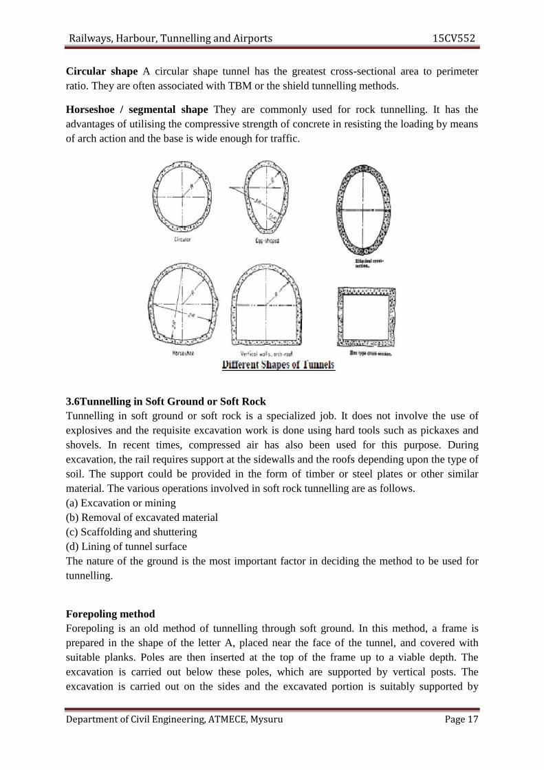
Railways, Harbour, Tunnelling and Airports 15CV552
Department of Civil Engineering, ATMECE, Mysuru Page 17
Circular shape A circular shape tunnel has the greatest cross-sectional area to perimeterratio. They are often associated with TBM or the shield tunnelling methods.
Horseshoe / segmental shape They are commonly used for rock tunnelling. It has theadvantages of utilising the compressive strength of concrete in resisting the loading by meansof arch action and the base is wide enough for traffic.
3.6Tunnelling in Soft Ground or Soft RockTunnelling in soft ground or soft rock is a specialized job. It does not involve the use ofexplosives and the requisite excavation work is done using hard tools such as pickaxes andshovels. In recent times, compressed air has also been used for this purpose. Duringexcavation, the rail requires support at the sidewalls and the roofs depending upon the type ofsoil. The support could be provided in the form of timber or steel plates or other similarmaterial. The various operations involved in soft rock tunnelling are as follows.(a) Excavation or mining(b) Removal of excavated material(c) Scaffolding and shuttering(d) Lining of tunnel surfaceThe nature of the ground is the most important factor in deciding the method to be used fortunnelling.
Forepoling methodForepoling is an old method of tunnelling through soft ground. In this method, a frame isprepared in the shape of the letter A, placed near the face of the tunnel, and covered withsuitable planks. Poles are then inserted at the top of the frame up to a viable depth. Theexcavation is carried out below these poles, which are supported by vertical posts. Theexcavation is carried out on the sides and the excavated portion is suitably supported by

Railways, Harbour, Tunnelling and Airports 15CV552
Department of Civil Engineering, ATMECE, Mysuru Page 18
timber. The entire section of the tunnel is covered thus. The process is repeated as the workprogresses.
Forepoling is a slow and tedious process and requires skilled manpower and strictsupervision. The method has to be meticulously repeated in sequence and there is no short cutfor the same.
Linear plate methodIn the linear plate method, timber is replaced by standard size pressed steel plates. The use ofpressed steel plates is a recent development. The method has the following advantages.
(a) The linear plates are light and can be handled easily.(b) The number of joints is less, as the linear plates are bigger in size, and as such themaintenance cost is low.(a) The steel plates are fireproof and can be safely used while working in compressed aircondition.(d) The necessary work can be done by semi-skilled staff.(e) There is considerable saving in terms of the excavation and concrete required.
Needle beam method

Railways, Harbour, Tunnelling and Airports 15CV552
Department of Civil Engineering, ATMECE, Mysuru Page 19
The needle beam method is adopted in terrains where the soil permits the roof of the tunnelsection to stand without support for a few minutes. In this method, a small drift is preparedfor inserting a needle beam consisting of two rail steel (RS) joists or I sections and is boltedtogether with a wooden block in the centre. The roof is supported on laggings carried on thewooden beam. The needle beam is placed horizontally with its front end supported on thedrift and the rear end supported on a vertical post resting on the lining of the tunnel. Jacks arefixed on the needle beam and the tunnel section is excavated by suitably incorporatingtimber. This method of tunnelling is more economical compared to other methods.
Ventilation of TunnelsA tunnel should be properly ventilated during as well as after the construction for the reasonsgiven below.(a) To provide fresh air to the workers during construction.(b) To remove the dust created by drilling, blasting, and other tunnelling operations.(c) To remove dynamite fumes and other objectionable gases produced by the use ofdynamites and explosives.The methods listed below are normally adopted for the ventilation of a tunnel.
Natural method of ventilation This is achieved by drilling a drift through the tunnel fromportal to portal. In most cases natural ventilation is not sufficient and artificial ventilation isstill required.Mechanical ventilation by blow-in method In the blow-in method, fresh air is forcedthrough a pipe or fabric duct by the means of a fan and supplied near the washing face (or thedrilling face; the drilling operation requires the washing of bore holes too). This method hasthe advantage that a fresh air supply is guaranteed where it is required the most. The
Railways, Harbour, Tunnelling and Airports 15CV552
Department of Civil Engineering, ATMECE, Mysuru Page 20
disadvantage is that the foul air and fumes have to travel a long distance before they can exitthe tunnel and in the process it is possible that the incoming fresh air will absorb some dustand smoke particles.Mechanical ventilation by exhaust method In the exhaust or blow-out method, foul air andfumes are pulled out through a pipe and is expelled by a fan. This sets up an air current thatfacilitates the entrance of fresh air into the tunnel. This method has the advantage that foul airis kept out of the washing face. The disadvantage, however, is that fresh air has to travel along distance before it can reach the washing face during which period it may absorb someheat and moisture.Combination of blow-in and blow-out methods By combining the blow-in and blow-outmethods using a blower and an exhaust system, respectively, a tunnel can be provided withthe best ventilation. After blasting the ground, the exhaust system is used to remove thesmoke and dust. After some time, fresh air is blown in through the ducts and the rotation ofthe fans is reversed to reverse the flow of air.
3.7 Drainage of TunnelsGood drainage of the tunnels is very essential in order for them to operate safely andsmoothly during the construction period as well as afterwards. The sources of water for thispurpose include ground water and water collected from the washing of bore holes. Waterseeping in up through the ground as well as from the washing of bore holes is collected insump wells and pumped out. If the tunnel is long, a number of sump wells are provided forthe collection of water. After the construction is over, drainage ditches are provided along thelength of the portion of the tunnel that slop from the portal towards the sump well and areused for pumping the water out. Sumps & pumps: The sumps connected by a pipe line are provided at a distance of
about 300 m & water is pumped from one sump to another until it is thrown out oftunnel opening
Grouting: The above method cannot be used, if water is percolating from the top ofthe tunnel. In such cases, the grouting is adopted to make the seams water-tight.
Pilot tunnel: In cases where pilot tunnel at a lower level than the main tunnel isconstructed parallel to it for drainage of water
Lining of TunnelsTunnels in loose rock and soft soils are liable to disintegrate and, therefore, a lining isprovided to strengthen their sides and roofs so as to prevent them from collapsing. Theobjectives of a lining are as follows.(a) Strengthening the sides and roofs to withstand pressure and prevent the tunnel fromcollapsing.(b) Providing the correct shape and cross section to the tunnel.(c) Checking the leakage of water from the sides and the top.(d) Binding loose rock and providing stability to the tunnel.(e) Reducing the maintenance cost of the tunnel.

Railways, Harbour, Tunnelling and Airports 15CV552
Department of Civil Engineering, ATMECE, Mysuru Page 21
Masonry:
Brick masonry: Brick masonry was the standard material for tunnel lining, but is nowrapidly going out of use, except in the case of underground sewers, as bricks are more acidresisting and suitable to carry sewage. A great disadvantage in using brick lining is thedifficulty in back packing the space between the tunnel roof and the extrodas of the archwhich at best has to be hand packed and is imperfect.
Stone masonry: It has more or less the same disadvantages as brick lining and in addition isvery heavy necessitating very strong centres. But is still used for lining the sides. Cementconcrete has become the standard material for tunnel lining in both rock and soft soils. Itsmain advantage lies in its plasticity which allows it to be well packed between the form andthe soil.
Timber: Is one of the oldest lining materials through of late, it is slowly yielding place toconcrete. It is used both as a temporary support during construction and as a permanentsupport later.
Concrete lining: Concrete lining is done using proper form-work. The form should show thetrue outline of the finished tunnel section
3.8 Recommended Questions
1. Differentiate harbour and port2. Briefly explain the types of tunnel3. Explain the construction of tunnel in rock and soft soil4. Explain lighting and ventilation in tunnel5. Define tide. Explain types of tides.6. Define dock. Explain the types.7. Write a note on transit shed8. Briefly explain navigational aids9. Define the following
i. Wharfii. Pier
iii. Jettyiv. Quay
3.9 Outcomes Develop layout plan of airport, harbor, dock and will be able relate the gained
knowledge to identify required type of visual and/or navigational aids for the same. Apply the knowledge gained to conduct surveying, understand the tunneling
activities.
3.10 Further Reading1. https://www.slideshare.net/saurabhsamant/tunnel-engineering2. http://www.aurecongroup.com/en/expertise/tunnels.aspx3. https://www.schnabel-eng.com/services/tunnel-engineering/
Railways, Harbour, Tunnelling and Airports 15CV552
Department of Civil Engineering, ATMECE, Mysuru Page 22
4. http://nptel.ac.in/courses/105103093/245. http://krishikosh.egranth.ac.in/bitstream/1/20349/1/3475.pdf6. http://www.dphu.org/uploads/attachements/books/books_2509_0.pdf7. http://www.johngrimes.co.uk/Data/Sites/1/media/case_study_pdfs/Ports-Docks-and-
Harbours-Civil-Engineering.pdf8. http://www.pfri.uniri.hr/~bopri/documents/14-ME-tal_001.pdf
Railways, Harbour, Tunnelling and Airports 15CV552
Department of Civil Engineering, ATMECE, Mysuru Page 1
Module – 4Airport Planning
Structure4.0 Introduction4.1 Objectives4.2 Airport classification:4.3 Components of Airport4.4 Aircraft Characteristics Affecting Airport Design:4.5 Criteria for airport site selection and ICAO stipulations4.6 Typical airport layouts:4.7 Recommended questions4.8 Outcomes4.9 Further Reading
4.0 Introduction
The planning of an airport is such a complex process that the analysis of one activity withoutregard to the effect on other activities will not provide acceptable solutions. An airportencompasses a wide range of activities which have different and often conflictingrequirements. Yet they are interdependent so that a single activity may limit the capacity ofthe entire complex. In the past airport master plans were developed on the basis of localaviation needs. In more recent times these plans have been integrated into an airport systemplan which assessed not only the needs at a specific airport site but also the overall needs ofthe system of airports which service an area, region, state, or country. If future airportplanning efforts are to be successful, they must be founded on guidelines established on thebasis of comprehensive airport system and master plans.
The elements of a large airport, It is divided into two major components, the airside and thelandside. The aircraft gates at the terminal buildings form the division between the twocomponents. Within the system, the characteristics of the vehicles, both ground and air, havea large influence on planning. The passenger and shipper of goods are interested primarily inthe overall door to-door travel time and not just the duration of the air journey. For thisreason access to airports is an essential consideration in planning.
4.1 Objectives1. Design and plan airport layout, design facilities required for runway, taxiway and
impart knowledge about visual aids
Air transport has the following characteristics:
1. Unbroken Journey: Air transport provides unbroken journey over land and sea. It is the
fastest and quickest means of transport.
2. Rapidity: Air transport had the highest speed among all the modes of transport.

Railways, Harbour, Tunnelling and Airports 15CV552
Department of Civil Engineering, ATMECE, Mysuru Page 2
3. Expensive: Air transport is the most expensive means of transport. There is huge
investment in purchasing aero planes and constructing of aerodromes.
4. Special Preparations: Air transport requires special preparations like wheelers links,
meteorological stations, flood lights, searchlights etc.
Fastest Mode of Transport:
Advantages:
1. High Speed: The supreme advantage of air transport is its high speed. It is the fastest mode
of transport and thus it is the most suitable mean where time is an important factor.
2. Comfortable and Quick Services: It provides a regular, comfortable, efficient and quick
service.
3. No Investment in Construction of Track: It does not require huge capital investment in the
construction and maintenance of surface track.
4. No Physical Barriers: It follows the shortest and direct route as seas, mountains or forests
do not come in the way of air transport.
5. Easy Access: Air transport can be used to carry goods and people to the areas which are
not accessible by other means of transport.
6. Emergency Services: It can operate even when all other means of transport cannot be
operated due to the floods or other natural calamities. Thus, at that time, it is the only mode
of transport which can be employed to do the relief work and provide the essential
commodities of life.
7. Quick Clearance: In air transport, custom formalities can be very quickly complied with
and thus it avoids delay in obtaining clearance.
8. Most Suitable for Carrying Light Goods of High Value: It is most suitable for carrying
goods of perishable nature which require quick delivery and light goods of high value such as
diamonds, bullion etc. over long distances.
9. National Defence: Air transport plays a very important role in the defence of a country.
Modern wars have been fought mainly by aeroplanes. It has upper hand in destroying the
enemy in a very short period of time. It also supports over wings of defence of a country.
10. Space Exploration: Air transport has helped the world in the exploration of space.
Disadvantages:
In spite of many advantages, air transport has the following limitations:
Railways, Harbour, Tunnelling and Airports 15CV552
Department of Civil Engineering, ATMECE, Mysuru Page 3
1. Very Costly: It is the costliest means of transport. The fares of air transport are so high that
it is beyond the reach of the common man.
2. Small Carrying Capacity: Its carrying capacity is very small and hence it is not suitable to
carry cheap and bulky goods.
3. Uncertain and Unreliable: Air transport is uncertain and unreliable as it is controlled to a
great extent by weather conditions. Unfavourable weather such as fog, snow or heavy rain
etc. may cause cancellation of scheduled flights and suspension of air service.
4. Breakdowns and Accidents: The chances of breakdowns and accidents are high as
compared to other modes of transport. Hence, it involves comparatively greater risk.
5. Large Investment: It requires a large amount of capital investment in the construction and
maintenance of aeroplanes. Further, very trained and skilled persons are required for
operating air service.
6. Specialised Skill: Air transport requires a specialised skill and high degree of training for
its operation.
7. Unsuitable for Cheap and Bulky Goods: Air transport is unsuitable for carrying cheap,
bulky and heavy goods because of its limited capacity and high cost.
8. Legal Restrictions: There are many legal restrictions imposed by various countries in the
interest of their own national unity and peace.
4.2 Airport classification:
Based on take-off and landing:• Conventional Take-Off and Landing Airport (CTOL)
Runway Length > 1500 m• Reduced Take-Off and Landing Airport (RTOL)
Runway Length 1000 to 1500 m• Short Take-Off and Landing Airport (STOL)
Runway Length 500 to 1000 m• Vertical Take-Off and Landing Airport (VTOL)
Operational area 25 to 50 sq m.
FAA Classification:Based on Air Craft Approach speed:
Approach Category Approach Speed (knots)A < 91B 91 – 120C 120 – 140D 141 – 165E >165

Railways, Harbour, Tunnelling and Airports 15CV552
Department of Civil Engineering, ATMECE, Mysuru Page 4
1 knot = 1.852 kmph3.3 Based on Function:
1. Civil AviationDomesticInternational
2. Military Aviation
ICAO Classification:
Based on Geometric Design:Airport
TypeBasic Runway Length (m) Width of Runway
Pavement (m)Maximum LongitudinalGrade (%)Maximum Minimum
A Over 2100 2100 45 1.5B 2099 1500 45 1.5C 1499 900 30 1.5D 899 750 22.5 2.0E 749 600 18 2.0
Based on Aircraft Wheel Characteristics:Code No. Single Isolated Wheel Load (kg) Tyre Pressure (kg/cm2)
1 45000 8.52 34000 7.03 27000 7.04 20000 7.05 13000 6.06 7000 5.07 2000 2.5
Aerodromes in India:
International Hubs: This category includes airports currently classified as InternationalAirports and having facilities of world standards.Delhi, Mumbai, Bangalore, Chennai, Kolkata, Hyderabad, ThiruvananthapuramRegional Hubs: Regional Airports will have to act as operational bases for regional airlinesand also have all the facilities currently postulated for model airports, including thecapability to handle limited international traffic. (Cochin, Ahmedabad etc)Domestic Airports:
Model Airports ( Indore, Nagpur, Vadodara, Bhubaneshwar) Operational (Udaipur, Kota, Kanpur)
Non Operational (Patna, Mysore)
Custom Airports:Having National and International tourist potential (Jaipur, Calicut, Agra, Gaya etc.)Civil Enclaves (At defense airfields) :
• Operational ( Bagdodara, Leh etc.)
Railways, Harbour, Tunnelling and Airports 15CV552
Department of Civil Engineering, ATMECE, Mysuru Page 5
• Non OperationalAir force aerodromes
• Not for civil use
Airport planning:
Objectives
Update aircraft activity forecasts for the airport.
Refine the size and layout of commercial service and general aviation areas.
Determine the preferred development alternatives for meeting airfield facility
requirements and FAA safety and design standards.
Provide a plan for improvement of the facility to accommodate increased usage and to
meet current FAA airport design standards.
Identify optimum landside uses, which will enhance the economic benefits of the
airport and that are compatible with airside development.
Prepare a schedule of development projects and reasonable cost estimates by which to
implement the improvements proposed herein (i.e. Capital Improvement Plan).
Develop realistic, phased development and maintenance plans for the airport.
Provide an Airport Layout Plan drawing set in accordance with current FAA
standards. Prepare an Environmental Overview for proposed development.
Prepare a proposed, comprehensive Airport Standards Manual for the Airport, which
incorporates the necessary information and regulations for users of the Airport.
Prepare a compatible land-use and height restriction plan for the airport vicinity
including recommended zoning protection within the airport influence zone.
Rehabilitating/reconstructing airfield pavements to provide a safe airport.
Providing a high quality and aesthetic facility that can be marketed for aerial tours and
economic development.
Identifying planning areas for future hangars and aviation related businesses.
4.3 Components of Airport
Therefore, the main components of airport are1. Runway2. Terminal Building3. Apron4. Taxiway5. Aircraft Stand
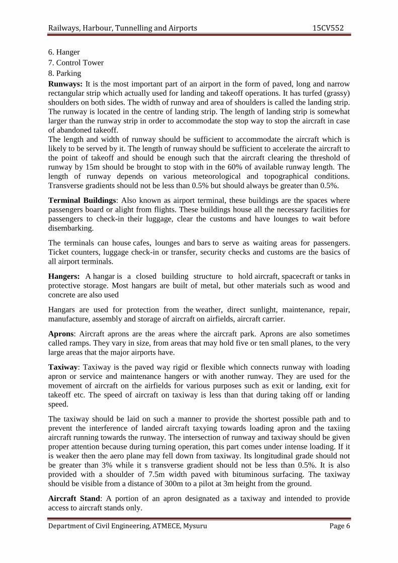
Railways, Harbour, Tunnelling and Airports 15CV552
Department of Civil Engineering, ATMECE, Mysuru Page 6
6. Hanger7. Control Tower8. ParkingRunways: It is the most important part of an airport in the form of paved, long and narrowrectangular strip which actually used for landing and takeoff operations. It has turfed (grassy)shoulders on both sides. The width of runway and area of shoulders is called the landing strip.The runway is located in the centre of landing strip. The length of landing strip is somewhatlarger than the runway strip in order to accommodate the stop way to stop the aircraft in caseof abandoned takeoff.The length and width of runway should be sufficient to accommodate the aircraft which islikely to be served by it. The length of runway should be sufficient to accelerate the aircraft tothe point of takeoff and should be enough such that the aircraft clearing the threshold ofrunway by 15m should be brought to stop with in the 60% of available runway length. Thelength of runway depends on various meteorological and topographical conditions.Transverse gradients should not be less than 0.5% but should always be greater than 0.5%.
Terminal Buildings: Also known as airport terminal, these buildings are the spaces wherepassengers board or alight from flights. These buildings house all the necessary facilities forpassengers to check-in their luggage, clear the customs and have lounges to wait beforedisembarking.
The terminals can house cafes, lounges and bars to serve as waiting areas for passengers.Ticket counters, luggage check-in or transfer, security checks and customs are the basics ofall airport terminals.
Hangers: A hangar is a closed building structure to hold aircraft, spacecraft or tanks inprotective storage. Most hangars are built of metal, but other materials such as wood andconcrete are also used
Hangars are used for protection from the weather, direct sunlight, maintenance, repair,manufacture, assembly and storage of aircraft on airfields, aircraft carrier.
Aprons: Aircraft aprons are the areas where the aircraft park. Aprons are also sometimescalled ramps. They vary in size, from areas that may hold five or ten small planes, to the verylarge areas that the major airports have.
Taxiway: Taxiway is the paved way rigid or flexible which connects runway with loadingapron or service and maintenance hangers or with another runway. They are used for themovement of aircraft on the airfields for various purposes such as exit or landing, exit fortakeoff etc. The speed of aircraft on taxiway is less than that during taking off or landingspeed.
The taxiway should be laid on such a manner to provide the shortest possible path and toprevent the interference of landed aircraft taxying towards loading apron and the taxiingaircraft running towards the runway. The intersection of runway and taxiway should be givenproper attention because during turning operation, this part comes under intense loading. If itis weaker then the aero plane may fell down from taxiway. Its longitudinal grade should notbe greater than 3% while it s transverse gradient should not be less than 0.5%. It is alsoprovided with a shoulder of 7.5m width paved with bituminous surfacing. The taxiwayshould be visible from a distance of 300m to a pilot at 3m height from the ground.
Aircraft Stand: A portion of an apron designated as a taxiway and intended to provideaccess to aircraft stands only.

Railways, Harbour, Tunnelling and Airports 15CV552
Department of Civil Engineering, ATMECE, Mysuru Page 7
Control Tower: A tower at an airfield from which air traffic is controlled by radio andobserved physically and by radar.
Parking: Parking is a specific area of airport at which vehicles park
Aircraft Characteristics:Component parts of an AircraftFollowing are the seven essential parts of an aero plane:-
1. Engine2. Flaps3. Fuselage4. Propeller5. Three Controls6. Tricycle Undercarriage7. Wings and tail
Engine:• The propulsion of the aircraft is mainly due to the engine.• Engine can be divided into a) Piston Engine b) Jet engine c) Rocket Engine.
Piston Engine:• Conventional type of aircraft engines• Operates at low altitudes and with moderate speeds (500-800 km/hr)• The aircraft is provided with gasoline fed engine which is driven by a propeller• The engine rotates a shaft with a huge torque and the torque so developed is absorbed
by the propeller mounted on a shaft.• When the rated speed is attained by the propeller, large quantity of air is hurled
rearwards (backwards) which pulls the aircraft forward and creates lift on the wings.Jet engine:

Railways, Harbour, Tunnelling and Airports 15CV552
Department of Civil Engineering, ATMECE, Mysuru Page 8
There are three types:• Turbo Jet• Turbo Propulsion• Ram Jet
Turbo Jet:• To start the machine, a compressor is rotated with a motor. As the compressor gains
its speed it sucks in air through the air intake and compresses it in the compressionchamber.
• The air- fuel mix is ignited in the chamber.• When the air-fuel mix burns the expanding gases pass through fan like blades of the
turbine• The hot exhaust gases escape with high velocity through the tail pipe which is tapered
at the end, giving a forward thrust to the engine.• The exhaust gases comes out of the tail pipe at a speed of 1600 kmph and such speed
of exhaust gases push the plane with speeds up to 800kmph• Turbo jet has a lower performance ratio at moderate altitude than at high altitudes
Turbo Propulsion:• The performance of a turbo propulsion aircraft is similar to that of turbo jet, except
that a propeller is provided in it.• The turbine in the turbo propeller extracts enough power• Its performance is equally satisfactory in low and high altitudes as compared to turbo
jet engines.• Turbo engines may acquire speeds 1280 – 2400 km/hr
Propeller:• Propeller is provided in the piston engine as well as the turbo prop engine• It has two or more blades which are driven round in a circular path.• The blades deflect the air backwards with acceleration and thus, forward thrust is
imparted to the airplane.
Fuselage:• Main body structure - All other components are attached to it• It Contains a) Cockpit or flight deck b) Passenger compartment
c) Cargo compartment• Produces a little lift, but can also produce a lot of drag.
The fuselage must possess the following characteristics:1. It is shaped to a fine point at the rear end and yet it should not be too fine so as to
make it unable to resist twisting stresses due to the wind.2. It should have enough depth for strength. But it should not be very deep because in
that case, the side area may become very large which is undesirable for safety andefficiency.
Wings:
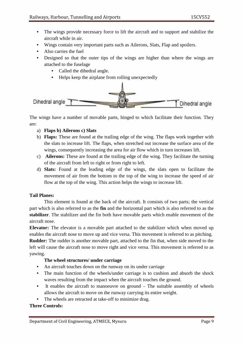
Railways, Harbour, Tunnelling and Airports 15CV552
Department of Civil Engineering, ATMECE, Mysuru Page 9
• The wings provide necessary force to lift the aircraft and to support and stabilize theaircraft while in air.
• Wings contain very important parts such as Ailerons, Slats, Flap and spoilers.• Also carries the fuel• Designed so that the outer tips of the wings are higher than where the wings are
attached to the fuselage• Called the dihedral angle.• Helps keep the airplane from rolling unexpectedly
The wings have a number of movable parts, hinged to which facilitate their function. Theyare:
a) Flaps b) Ailerons c) Slatsb) Flaps: These are found at the trailing edge of the wing. The flaps work together with
the slats to increase lift. The flaps, when stretched out increase the surface area of thewings, consequently increasing the area for air flow which in turn increases lift.
c) Ailerons: These are found at the trailing edge of the wing. They facilitate the turningof the aircraft from left to right or from right to left.
d) Slats: Found at the leading edge of the wings, the slats open to facilitate themovement of air from the bottom to the top of the wing to increase the speed of airflow at the top of the wing. This action helps the wings to increase lift.
Tail Planes:This element is found at the back of the aircraft. It consists of two parts; the vertical
part which is also referred to as the fin and the horizontal part which is also referred to as thestabilizer. The stabilizer and the fin both have movable parts which enable movement of theaircraft nose.Elevator: The elevator is a movable part attached to the stabilizer which when moved upenables the aircraft nose to move up and vice versa. This movement is referred to as pitching.Rudder: The rudder is another movable part, attached to the fin that, when side moved to theleft will cause the aircraft nose to move right and vice versa. This movement is referred to asyawing.
The wheel structures/ under carriage• An aircraft touches down on the runway on its under carriage• The main function of the wheels/under carriage is to cushion and absorb the shock
waves resulting from the impact when the aircraft touches the ground.• It enables the aircraft to manoeuvre on ground – The suitable assembly of wheels
allows the aircraft to move on the runway carrying its entire weight.• The wheels are retracted at take-off to minimize drag.
Three Controls:
Railways, Harbour, Tunnelling and Airports 15CV552
Department of Civil Engineering, ATMECE, Mysuru Page 10
When a plane is in flight, there are three imaginary axes of rotation. These lines runthrough the weight center (or center of gravity) of the plane. The airplane’s rotation aroundthe y axis is called yaw; rotation around the x axis is called pitch, and rotation around the zaxis is called roll.Controls:
• Roll is controlled by the ailerons Used to raise and lower the wings. Turning the control wheel left causes the left aileron to raise and lowers the right
aileron. The plane rolls left. Turning the control wheel right causes the right aileron to raise and lowers the left
aileron. The plane rolls right.• Pitch is controlled by the elevators on the tail of the plane.• Yaw is controlled by the rudders.
4.4 Aircraft Characteristics Affecting Airport Design:1. Engine and Propulsion2. Size3. Aircraft capacity4. Aircraft speed5. Minimum turning radius6. Minimum circling radius7. Aircraft weight and wheel arrangements8. Range9. Noise10. Take off and landing distances11. Tire pressure and contact area.
Size of Aircraft: Size depends upon1. Wing Span2. Length ( Fuselage length)3. The maximum height4. Distance between main gears5. Wheel base6. Tail Width
Size decides load carrying capacityWing Span decides: The apron size, taxiway clearance, hangar size turning radius – ICAOclassificationThe length of Aircraft decides: The width of exit taxiway, apron size, length of hanger etc.The height decides: The height of hangers and its gate.The gear treads and wheel base affect the minimum turning radius of the aircraft.
Air Craft capacity:Aircraft capacity determines;
Number of Passengers

Railways, Harbour, Tunnelling and Airports 15CV552
Department of Civil Engineering, ATMECE, Mysuru Page 11
Baggage Cargo and
Fuel.
Aircraft Speed:• Speed now a days is measured in mach i.e. the speed of sound• Piston engines – 500 to 800 km/hr (0.6 to 0.8 mach )• Jet Engines - 1200 – 2400 km/hr (1 to 2 mach )• Rocket engines - > 4800 km/hr ( 4 mach and above)• Speed determines the travel time.
Speed has nothing to do with planning of airport, it gives an idea of the time of arrivalof aircraft. However approach speed decides runway length.
Minimum Turning Radius: It is necessary to know the minimum turning radius of anaircraft to decide the radius of taxiways and to ascertain its position in the landing aprons andhangars.
Minimum Circling radius: A certain minimum circling radius in space is required for theaircraft to take a smooth turn. It is known as the minimum circling radius. It depends upon,
• Type of aircraft• Air traffic volume• Weather conditions• The knowledge of minimum circling radius helps in separating two nearby airports by
adequate distance.• For jet planes its around 80 km• For other planes its around 8 – 15 km.• If minimum circling radius is not provided it will reduce the airport capacity and
adjustment of timings for landing and take-off of aircrafts between the airports needsto be adjusted.
Aircraft Weight and Wheel Configuration:• Governs the length and thickness of the runways, taxiways.• Number of wheels to be provided depends on aircraft weight.• Structural design of the airport is based on the total load of the aircraft.
The weight of the aircraft may be classified into:• Operating empty Weight – Weight of empty aircraft, including its crew and
all equipment needed for flight, but excluding passengers, fuel load and cargo.• Pay load – revenue producing load which consists of passengers, mail and
cargo.• Fuel Load- Weight of the fuel carried by the aircraft required for the trip and
certain reserve. It may vary from 9% to 40% of the total gross weight .
Wheel Configurations:-
Railways, Harbour, Tunnelling and Airports 15CV552
Department of Civil Engineering, ATMECE, Mysuru Page 12
More number of wheels lesser is the load on the runway pavement.• Depends upon the size and type of aircraft.• Wheel configuration also decides minimum turning radius.
Fuel Spillage:-• The spilling of fuels and lubricants occur in loading aprons and hangers.• It is difficult to avoid spilling completely.• The bituminous pavements are seriously affected by fuel spillage. Hence the areas of
bituminous pavements below the fuel inlets, the engines, and main landing gears arekept under constant watch by the airport authorities.
• Causes skidding of aircrafts.
Range:• The distance that an aircraft can fly without refueling is called range.• As range increases pay load decreases and vice versa.
Noise: This is a big problem in the areas where airports are quiet near to the developed areas.Efforts are being made to bring it to minimum possible level.The major source of noise is:
• Engine• Machinery prominent during landing• Primary jet, prominent during take off• It causes Sleep disturbance, deafness, irritability, Loss of Concentration.
Factors determining airport catchment areaThe need and potential for the development of existing airports or for the construction
of new ones is determined by a number of internal and external factors. Internal factorsinvolve, among other things, the airport management policy, as the economic success of anairport is not only an effect of general air transport development trends, but also of thesuccess or failure of the business strategy pursued by airport management. Another key factoris the importance of cooperation between airport managers and local government. The lattershould be interested in airport development given the stimuli to economic growth itgenerates. Such cooperation is usually based on the fact that the city or the region is often akey shareholder in airport management companies. The cooperation may take the form ofinvolvement (including financial participation) of the local government authority in theopening and promotion of air connections offered by the airport. Also the role of localgovernment in managing areas surrounding the airport is important as it has a direct impacton the potential for its undisturbed operation and further development. From the perspectiveof the catchment area of an airport, i.e. the impact of the airport on the market for airtransport, local and regional government have the fundamental task of organising the publictransport serving the airport.
The group of external factors is more varied as it comprises the spatial, social andeconomic determinants of airport development. The former (spatial) are mainly local innature, i.e. they concern the immediate surroundings. The latter (socioeconomic) address
Railways, Harbour, Tunnelling and Airports 15CV552
Department of Civil Engineering, ATMECE, Mysuru Page 13
development in a wider sense, i.e. the transport sector itself as well as the region and thecountry. The two groups of conditions are interrelated. A good spatial system within whichthe airport functions may remain unexploited if the region does not develop fast enough forthe airport surroundings to represent attractive investment areas. And conversely, stimuli foreconomic development, such as increased mobility of the region’s population, may bearrested by limited airport throughput and lack of development prospects. In the context of allthe above conditions, transport solutions have a role to play as they stimulate both the airportitself and its surroundings.
4.5 Criteria for airport site selection and ICAO stipulationsThe selection of a suitable site for an airport depends upon the class of airport underconsideration. However if such factors as required for the selection of the largest facility areconsidered the development of the airport by stages will be made easier and economical. Thefactors listed below are for the selection of a suitable site for a major airport installation:
1. Regional plan2. Airport use3. Proximity to other airport4. Ground accessibility5. Topography6. Obstructions7. Visibility8. Wind9. Noise nuisance10. grading, drainage and soil characteristics11. Future development12. Availability of utilities from town13. Economic consideration
Regional plan: The site selected should fit well into the regional plan there by forming it anintegral part of the national network of airport.Airport use: the selection of site depends upon the use of an airport. Whether for civilian orfor military operations. However during the emergency civilian airports are taken over by thedefence. Therefore the airport site selected should be such that it provides natural protectionto the area from air roads. This consideration is of prime importance for the airfields to belocated in combat zones. If the site provides thick bushes.Proximity to other airport: the site should be selected at a considerable distance from theexisting airports so that the aircraft landing in one airport does not interfere with themovement of aircraft at other airport. The required separation between the airports mainlydepends upon the volume of air traffic.Ground accessibility: the site should be so selected that it is readily accessible to the users.The airline passenger is more concerned with his door to door time rather than the actual time

Railways, Harbour, Tunnelling and Airports 15CV552
Department of Civil Engineering, ATMECE, Mysuru Page 14
in air travel. The time to reach the airport is therefore an important consideration especiallyfor short haul operations.Topography: this includes natural features like ground contours trees streams etc. A raisedground a hill top is usually considered to be an ideal site for an airport.Obstructions: when aircraft is landing or taking off it loses or gains altitude very slowly ascompared to the forward speed. For this reason long clearance areas are provided on eitherside of runway known as approach areas over which the aircraft can safely gain or losealtitude.Visibility: poor visibility lowers the traffic capacity of the airport. The site selected shouldtherefore be free from visibility reducing conditions such as fog smoke and haze. Foggenerally settles in the area where wind blows minimum in a valley.Wind: runway is so oriented that landing and takeoff is done by heading into the wind shouldbe collected over a minimum period of about five years.Noise nuisance: the extent of noise nuisance depends upon the climb out path of aircraft typeof engine propulsion and the gross weight of aircraft. The problem becomes more acute withjet engine aircrafts. Therefore the site should be so selected that the landing and takeoff pathsof the aircrafts pass over the land which is free from residential or industrial developments.Grading, drainage and soil characteristics: grading and drainage play an important role inthe construction and maintenance of airport which in turn influences the site selection. Theoriginal ground profile of a site together with any grading operations determines the shape ofan airport area and the general pattern of the drainage system. The possibility of floods at thevalley sites should be investigated. Sites with high water tables which may require costlysubsoil drainage should be avoided.Future development: considering that the air traffic volume will continue to increase infuture more member of runways may have to be provided for an increased traffic.
4.6 Typical airport layouts:The layout of an airport mainly depends on the basic configurations of the runways. The
other airport elements are then correlated in such a way that an integrated layout is developedgiving smooth flow of traffic, keeping in mind the taxi distances to a minimum, providingshortest route for the passengers. A proper airport layout provides full functional efficiencywith the minimum space utilization. An engineer should attempt to provide the simplestdesign which yields the optimum service to air passengers. A good airfield layout shouldposses the following characteristic:
Landing, taxing and taking off as independent operations without interference. Shortest taxiway distance from loading runway end. Safe runway length Safe approaches Excellent control tower visibility Adequate loading apron space Sufficient terminal building facilities Sufficient land area to permit subsequent expansion Lowest possible cost of construction.

Railways, Harbour, Tunnelling and Airports 15CV552
Department of Civil Engineering, ATMECE, Mysuru Page 15

Railways, Harbour, Tunnelling and Airports 15CV552
Department of Civil Engineering, ATMECE, Mysuru Page 16
Parking and circulation area
Since the airport users normally arrive at the airport in automobiles, access roads and parkingfacilities are of vital importance in the airport design. The circulation of traffic and locationof parking lots should be such that access to the terminal building is as convenient aspossible.
Access roads are planned to provide fact connections between the airport and the city. One ofthe present disadvantages of air travel is that the time saved through air travel is lost inground transportation. Circulation of vehicular traffic within the terminal area is alsocarefully planned. It is essential to categorize the vehicular traffic to provide the road networksatisfying the specific needs of each traffic category. Broadly the vehicular traffic is classifiedas passengers, visitors and service personnel.
The area closest to the terminal building entrance may be used for short time parking forenplaning and deplaning passengers. Sufficient space is to be provided for passengers cars,adjacent to the entrance of the terminal building boarding and alighting of passengers withoutany congestion and delay. Separate parking area is provided for the staff personnel.
For the most efficient airport vehicular circulation and parking system, the following pointsare considered:
Ease of passenger unloading and loading at the terminal building One way traffic wherever possible A minimum of driveway intersection Adequate driveway width to permit overtaking Sufficiently and clearly defined parking and circulation routes Well lighted routes for pedestrians and vehicles
For determining the size and type of parking facility necessary, a traffic survey shouldbe conducted. FAA suggests that the size of the public parking facility should be based on 1.5to 2 cars for each peak hour passenger. The pattern of parking is dedicated by the shape andsize of the parking area available. The basic parking patterns usually adopted are shown in fig

Railways, Harbour, Tunnelling and Airports 15CV552
Department of Civil Engineering, ATMECE, Mysuru Page 17
4.7 Recommended Questions1. Enumerate the various factors which you would keep in view while selecting a
suitable site for an airport.2. Write the classification of airports based on ICAO and FAA?3. Explain the component parts of airports.4. Explain the typical airports layouts with neat sketch.5. Explain the aircraft characteristics which affect the airport design.6. What are the characteristics of air transport?
4.8 Outcomes1. Acquires capability of choosing alignment and also design geometric aspects of
runway, and taxiway.
4.9 Further Reading1. http://science.howstuffworks.com/transport/flight/modern/airport1.htm2. http://www.aai.aero/public_notices/aaisite_test/main_new.jsp3. http://nptel.ac.in/reviewed_pdfs/105107123/lec31.pdf4. http://www.ucalgary.ca/EN/civil/NLAircraft/Atrgpap.pdf

Railways, Harbour, Tunnelling and Airports 15CV552
Department of Civil Engineering, ATMECE, Mysuru Page 1
Module – 5Airport Design
Structure5.0 Introduction5.1 Objectives5.2 Wind Rose Diagram5.3 Runway Length5.4 Basic Elements of a Runway:5.5 Runway Geometric Design5.6 Taxiway Planning5.7 Airport Zones5.8 Passenger Facilities and Services5.9 Airport Making and Lighting5.10 Recommended Questions5.11 Outcomes5.12 Further Reading
5.0 Introduction
Orientation
According to the International Civil Aviation Organization (ICAO) a runway is a "definedrectangular area on a land aerodrome prepared for the landing and takeoff of aircraft".
The orientation of the runway is an important consideration in airport planning and design.The correct runway orientation maximizes the possible use of the runway throughout the yearaccounting for a wide variety of wind conditions. FAA and ICAO regulations establish rulesabout runway orientation and their expected coverage Runway Location Considerations.FAA mandates identification standards for airport layout that is meant to assist pilots in easilyrecognizing runways.
Runway is usually oriented in the direction of prevailing winds. The head wind i.e. the winddirection of wind opposite to the direction of landing and taking-off provides greater lift onthe wings of the aircraft when it is taking-off. As such the aircraft rises above the groundmuch earlier and in a shorter length of runway. During landing, the head wind provides abreaking effect and the aircraft comes to a stop in a smaller length of runway. Landing andtake-off operations, if done along the wind direction, would require longer runway.
The challenge for the designer is to accommodate all of the aircraft using the facility in areliable and reasonable manner.
In navigation, all measurement of direction is performed by using the numbers of a compass.A compass is a 360° circle where 0/360° is North, 90° is East, 180° is South, and 270° isWest, as shown in figure.

Railways, Harbour, Tunnelling and Airports 15CV552
Department of Civil Engineering, ATMECE, Mysuru Page 2
5.1 Objectives
1. Design and plan airport layout, design facilities required for runway, taxiway andimpart knowledge about visual aids
5.2 Wind Rose DiagramRunway orientation using wind rose:
The wind data, i.e., direction, duration and intensity are graphically represented by adiagram called wind rose. The plotting of the wind rose diagrams can be done in thefollowing two ways
Type I: Showing direction and duration of windType II: Showing direction, duration and intensity of windCross wind component:
It is not possible to get the direction of opposite wind parallel to the centre line of therunway length everyday or throughout the year.
If the direction of wind is at an angle to the runway centre line, its component alongthe direction of runway will be V Cos θ and that normal to the runway centre line will be VSin θ where V is the wind velocity. The normal component of the wind is called cross windcomponent. Cross wind component should not exceed 25 kmph for mixed traffic.
Wind coverage:
The percentage of time in a year during which the cross wind component remainswithin the limit of 25 kmph is called wind coverage of the runway.
According to FAA, the runway handling mixed air traffic should be so planned thatfor 95 % of time in a year. For busy airports, the wind coverage may be increased to 98 % to100%.
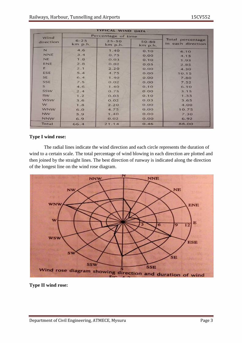
Railways, Harbour, Tunnelling and Airports 15CV552
Department of Civil Engineering, ATMECE, Mysuru Page 3
Type I wind rose:
The radial lines indicate the wind direction and each circle represents the duration ofwind to a certain scale. The total percentage of wind blowing in each direction are plotted andthen joined by the straight lines. The best direction of runway is indicated along the directionof the longest line on the wind rose diagram.
Type II wind rose:

Railways, Harbour, Tunnelling and Airports 15CV552
Department of Civil Engineering, ATMECE, Mysuru Page 4
– From the wind data table, it is observed that the percentage of time during which the windvelocity is less than 6 kmph works out to (100-88) = 12. this period is called the calmperiod and does not influence the operations of landing and take-off because of low windvelocity.
– Thus the wind velocities below 6 kmph have no effect on the fixing of orientation of arunway.
– Thus, the wind velocities below 6 Kmph have no effect on the fixing of orientation of arunway.
– The concentric circles with radii corresponding to 6, 25, 50, and 80 kmph to some scaleare drawn. Thus, each circle represents the wind velocity to some scale
– Starting with centre of the concentric circles, the 16 radial directions are shown on theouter circle. The mid points of 16 arcs on the outermost concentric circle are marked andthey are given the cardinal directions of compass like N, NNE, NE, ENE, E, etc.
– The recorded duration of winds and expressed as percentage are shown for each cardinaldirection. It may be noted that the cardinal direction is central to sector.
– A transparent rectangular template or paper strip is taken. Its length should be slightlygreater than the diameter of the wind rose diagram and its width should be greater thantwice the allowable cross wind component i.e. 25 kmph.
– The scale for cross wind component should be the same as that of the concentric circles ofthe wind rose diagram.
– Along the centre of the length of this template, a line is marked corresponding to thedirection of runway.
– The two parallel lines, one on either side of the centre-line, is drawn at a distance equal tothe allowable cross wind component i.e. 25 Kmph from the centre line. In other words, thetwo parallel lines are 50 Kmph away from each other.
– The wind rose diagram is fixed in position on a drawing board.

Railways, Harbour, Tunnelling and Airports 15CV552
Department of Civil Engineering, ATMECE, Mysuru Page 5
– A hole is drilled in the centre of the template and it is placed on the wind rose diagramsuch that its centre lies over the centre of the wind rose diagram.
– In this position, the template is fixed by a pin passing through its centre so that thetemplate can rotate about this pin as axis.
– The template is rotated and is placed along a particular direction.– In this position of the template, the duration of 6-25, 25-50 and 50-80 Kmph winds are
read for the cardinal directions (N, NNE, NE etc.) lying between the two extreme parallelline marked on the template.
– The sum of all these durations is expressed as the percentage and it gives the total windcoverage for that direction.
5.3 Runway Length• It is the length of runway under the following assumed conditions:
i. Airport altitude is at sea level.ii. Temperature at the airport is standard 15°C.
iii. Runway is levelled in the longitudinal direction.iv. No wind is blowing on runway.v. Aircraft is loaded to its full loading carrying capacity.
vi. En-route temperature in standard.5.3.1 Corrections for elevation, temperature and gradient
The basic runway length as discussed earlier is for mean sea level elevation havingstandard atmospheric conditions. Necessary corrections are therefore applied for any changein elevation, temperature and gradient for the actual site of construction.
5.3.2 Correction for elevation
• As the elevation increases, the air density reduces. This is in turn reduces the lift onthe wings of the aircraft and the aircraft requires greater ground speed before it canrise into the air.
• To achieve greater speed, longer length of runway is required.• ICAO recommends that the basic runway length should be increased at the rate of 7
per cent per 300m rise in elevation above the mean sea level.
5.3.3 Correction for temperature
• The rise in airport reference temperature has the same effect as that of the increase inelevation. Airport reference temperature is defined as the monthly mean of averagedaily temperature( Ta ) for the hottest month of the year plus one third the differenceof this temperature ( Ta ) and the monthly mean of the maximum daily temperature (Tm ) for the same month of the year.
• Thus airport reference temperature=• ICAO recommends that the basic runway length after having been corrected for
elevation, should be further increased at the rate of 1 percent for every 1°C rise ofairport reference temperature above the standard atmospheric temperature at thatelevation.
5.3.4 Check for total correction for elevation plus temperature

Railways, Harbour, Tunnelling and Airports 15CV552
Department of Civil Engineering, ATMECE, Mysuru Page 6
• ICAO further recommends that, if the total correction for elevation plus temperatureexceeds 35percent of the basic runway length, these corrections should then thefurther checked up by conducting specific studies at the site by model tests.
5.3.5 Correction for gradient
• Steeper gradient results in greater consumption of energy and as such longer length ofrunway is required to attain the desired ground speed.
• ICAO does not recommend any specific correction for the gradient.• FAA recommends that the runway length after having been corrected for elevation
and temperature should be further increased at the rate of 20 % for every 1 percent ofeffective gradient.
• Effective gradient is defined as the maximum difference in elevation between thehighest and lowest points of runway divided by the total length of runway.
5.4 Basic Elements of a Runway:
1. Structural Pavement2. Shoulders3. Runway Strip4. Blast pad5. Runway End safety area6. Stop way and Clear way.
Structural pavement: It is the paved area whose length and width is designed to ensure asafe operating surface. It supports the airplane load
Shoulders: The shoulders are adjacent to the structural pavement, which are designed toresist erosion due to jet blast and to accommodate maintenance equipment and patrol.
Runway Strip: It includes the structural pavement, shoulders and an area that is cleared andgraded. This area should be capable of supporting fire, crash rescue and snow removalequipment.
Blast Pad: The blast pad is an area designed to prevent erosion of surfaces adjacent to theends of the runways which are subjected to repeated jet blasts and to minimize excessiveground maintenance. The area is either paved or planted with turf.
5.5 Runway Geometric Design
• Factors considered in geometric design of runways:i. Runway length
ii. Runway widthiii. Width and length of safety areaiv. Transverse gradientv. Longitudinal and effective gradient
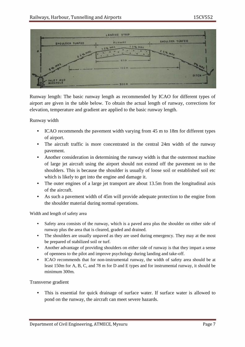
Railways, Harbour, Tunnelling and Airports 15CV552
Department of Civil Engineering, ATMECE, Mysuru Page 7
Runway length: The basic runway length as recommended by ICAO for different types ofairport are given in the table below. To obtain the actual length of runway, corrections forelevation, temperature and gradient are applied to the basic runway length.
Runway width
• ICAO recommends the pavement width varying from 45 m to 18m for different typesof airport.
• The aircraft traffic is more concentrated in the central 24m width of the runwaypavement.
• Another consideration in determining the runway width is that the outermost machineof large jet aircraft using the airport should not extend off the pavement on to theshoulders. This is because the shoulder is usually of loose soil or established soil etcwhich is likely to get into the engine and damage it.
• The outer engines of a large jet transport are about 13.5m from the longitudinal axisof the aircraft.
• As such a pavement width of 45m will provide adequate protection to the engine fromthe shoulder material during normal operations.
Width and length of safety area
• Safety area consists of the runway, which is a paved area plus the shoulder on either side ofrunway plus the area that is cleared, graded and drained.
• The shoulders are usually unpaved as they are used during emergency. They may at the mostbe prepared of stabilized soil or turf.
• Another advantage of providing shoulders on either side of runway is that they impart a senseof openness to the pilot and improve psychology during landing and take-off.
• ICAO recommends that for non-instrumental runway, the width of safety area should be atleast 150m for A, B, C, and 78 m for D and E types and for instrumental runway, it should beminimum 300m.
Transverse gradient
• This is essential for quick drainage of surface water. If surface water is allowed topond on the runway, the aircraft can meet severe hazards.
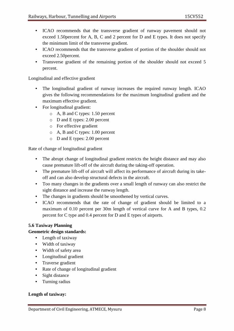
Railways, Harbour, Tunnelling and Airports 15CV552
Department of Civil Engineering, ATMECE, Mysuru Page 8
• ICAO recommends that the transverse gradient of runway pavement should notexceed 1.50percent for A, B, C and 2 percent for D and E types. It does not specifythe minimum limit of the transverse gradient.
• ICAO recommends that the transverse gradient of portion of the shoulder should notexceed 2.50percent.
• Transverse gradient of the remaining portion of the shoulder should not exceed 5percent.
Longitudinal and effective gradient
• The longitudinal gradient of runway increases the required runway length. ICAOgives the following recommendations for the maximum longitudinal gradient and themaximum effective gradient.
• For longitudinal gradient:o A, B and C types: 1.50 percento D and E types: 2.00 percento For effective gradiento A, B and C types: 1.00 percento D and E types: 2.00 percent
Rate of change of longitudinal gradient
• The abrupt change of longitudinal gradient restricts the height distance and may alsocause premature lift-off of the aircraft during the taking-off operation.
• The premature lift-off of aircraft will affect its performance of aircraft during its take-off and can also develop structural defects in the aircraft.
• Too many changes in the gradients over a small length of runway can also restrict thesight distance and increase the runway length.
• The changes in gradients should be smoothened by vertical curves.• ICAO recommends that the rate of change of gradient should be limited to a
maximum of 0.10 percent per 30m length of vertical curve for A and B types, 0.2percent for C type and 0.4 percent for D and E types of airports.
5.6 Taxiway PlanningGeometric design standards:
• Length of taxiway• Width of taxiway• Width of safety area• Longitudinal gradient• Traverse gradient• Rate of change of longitudinal gradient• Sight distance• Turning radius
Length of taxiway:
Railways, Harbour, Tunnelling and Airports 15CV552
Department of Civil Engineering, ATMECE, Mysuru Page 9
It should be as short as practicable. This will save the fuel consumption. No specifications are recommended by any organisation for limiting the length of
taxiway.
Width of taxiway: The width of taxiway is much lower than the runway width. The speed of the aircraft on a taxiway is also lower than the speed on runway. The pilot can comfortably manoeuvre the aircraft over a smaller width of taxiway
than on a runway.
Width of safety area: This area includes taxiway pavement shoulders on either side that may be partially
paved plus the area that is graded and drained. This may extend up to a point where it intersects a parallel runway, taxiway and
apron. Bitumen treated shoulders are normally used. The shoulders must be thick enough to support the airport petrol vehicles and the
sweeping equipment.
Longitudinal gradient: If the gradient is steep, there will be greater fuel consumption.
ICAO recommends that the longitudinal gradient should not exceed 1.5 percent for Aand B types and 3 percent for other types of airports.
Transverse gradient: This is essential for quick drainage of surface water. ICAO recommends that for taxiway pavement like runway, the transverse gradient
should not exceed a value of 1.5 percent for A, B and C types and 2 percent for D andE types of airports.
ICAO does not specify any value for the transverse slope of taxiway shoulders.
FAA recommends that it should be 5 percent for the first 3 m and 2 percent thereafterfor all types of airports.
Rate of change of longitudinal gradient: ICAO recommends that rate of change of slope in longitudinal direction should not
exceed 1 percent per 30 m length of vertical curve for A, B and C types and 1.2percent for D and E types of airports.
Sight distance: ICAO recommends that the surface of a taxiway must be visible from 3 m height for a
distance of 300 m for A, B and C types and distance of 250 m must be visible from2.1 m height for D and E types of airports.
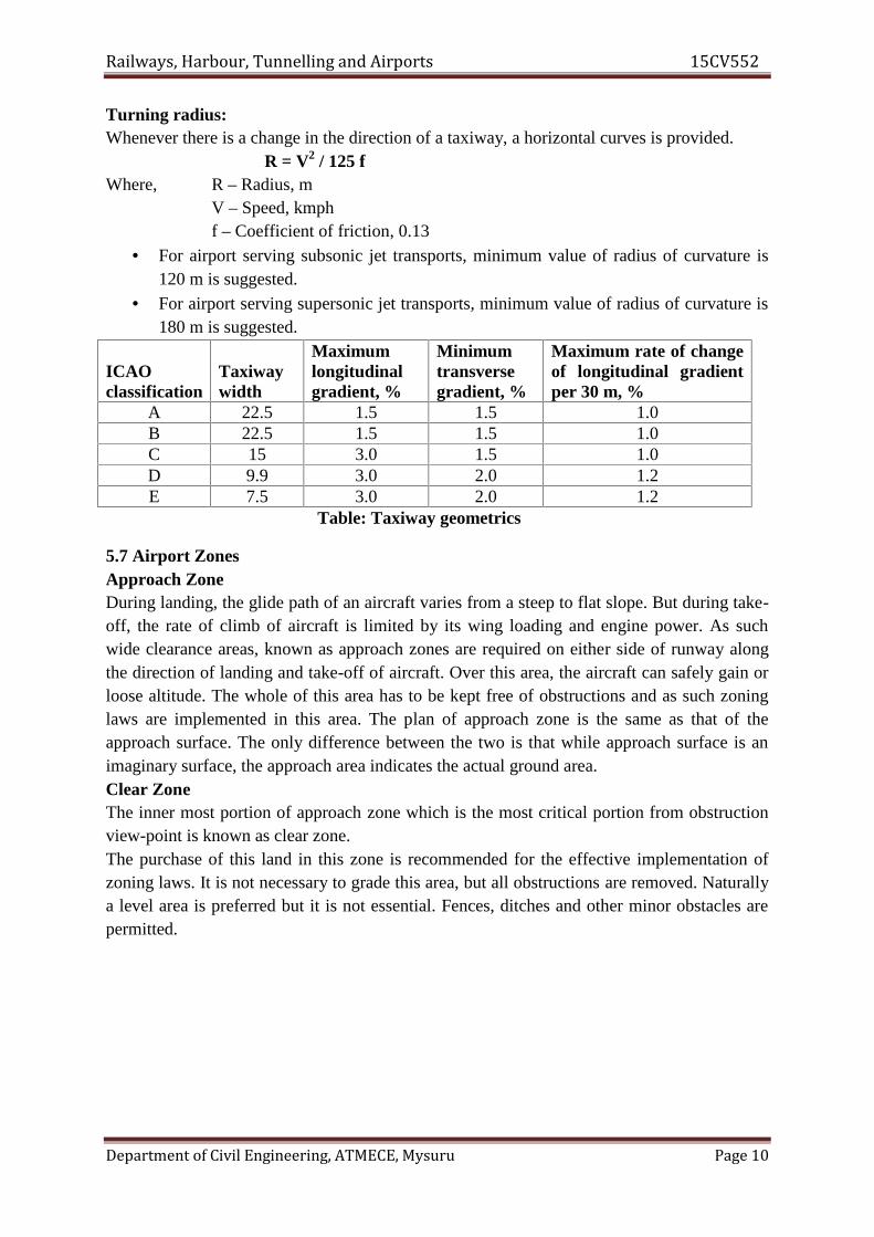
Railways, Harbour, Tunnelling and Airports 15CV552
Department of Civil Engineering, ATMECE, Mysuru Page 10
Turning radius:Whenever there is a change in the direction of a taxiway, a horizontal curves is provided.
R = V2 / 125 fWhere, R – Radius, m
V – Speed, kmphf – Coefficient of friction, 0.13
For airport serving subsonic jet transports, minimum value of radius of curvature is120 m is suggested.
For airport serving supersonic jet transports, minimum value of radius of curvature is180 m is suggested.
ICAOclassification
Taxiwaywidth
Maximumlongitudinalgradient, %
Minimumtransversegradient, %
Maximum rate of changeof longitudinal gradientper 30 m, %
A 22.5 1.5 1.5 1.0B 22.5 1.5 1.5 1.0C 15 3.0 1.5 1.0D 9.9 3.0 2.0 1.2E 7.5 3.0 2.0 1.2
Table: Taxiway geometrics
5.7 Airport ZonesApproach ZoneDuring landing, the glide path of an aircraft varies from a steep to flat slope. But during take-off, the rate of climb of aircraft is limited by its wing loading and engine power. As suchwide clearance areas, known as approach zones are required on either side of runway alongthe direction of landing and take-off of aircraft. Over this area, the aircraft can safely gain orloose altitude. The whole of this area has to be kept free of obstructions and as such zoninglaws are implemented in this area. The plan of approach zone is the same as that of theapproach surface. The only difference between the two is that while approach surface is animaginary surface, the approach area indicates the actual ground area.Clear ZoneThe inner most portion of approach zone which is the most critical portion from obstructionview-point is known as clear zone.The purchase of this land in this zone is recommended for the effective implementation ofzoning laws. It is not necessary to grade this area, but all obstructions are removed. Naturallya level area is preferred but it is not essential. Fences, ditches and other minor obstacles arepermitted.
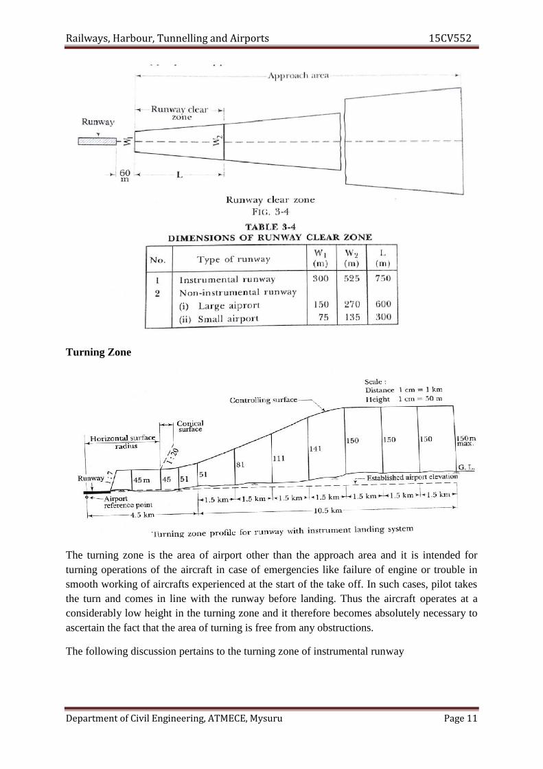
Railways, Harbour, Tunnelling and Airports 15CV552
Department of Civil Engineering, ATMECE, Mysuru Page 11
Turning Zone
The turning zone is the area of airport other than the approach area and it is intended forturning operations of the aircraft in case of emergencies like failure of engine or trouble insmooth working of aircrafts experienced at the start of the take off. In such cases, pilot takesthe turn and comes in line with the runway before landing. Thus the aircraft operates at aconsiderably low height in the turning zone and it therefore becomes absolutely necessary toascertain the fact that the area of turning is free from any obstructions.
The following discussion pertains to the turning zone of instrumental runway

Railways, Harbour, Tunnelling and Airports 15CV552
Department of Civil Engineering, ATMECE, Mysuru Page 12
Any object located within a distance of 4.5 km from airport reference point (ARP) isconsidered as an obstruction, if its height exceeds 51 m above the ground or the establishedairport elevation whichever is more.
Any object which is located beyond a distance of 4.5 km from the ARP is considered as anobstruction, if its height exceeds 51 m plus 30 m for each additional 1.5 km distance from theARP or if it exceeds 150 m within a distance of 15 km from the ARP.
5.8 Passenger Facilities and Services1. Baggage Enquiries: Baggage allowances are determined by airlines and will depend
on a variety of factors such as fare paid and aircraft type, so be sure to check baggageallowance information well in advance of setting off to Airport.
2. Internet Access: If you have a mobile internet device such as a laptop or Smartphone,you can also print vital documents at the kiosks, ensuring you can brush up on lastminute paperwork during the flight.
3. Escape Lounge: Escape Lounge now for complimentary food and drink, free Wi-Fiand to simply unwind before fly.
4. Prayer Room: If someone need somewhere for prayer or quiet reflection, can visitprayer rooms in the main Terminal Building.
5. VAT Refunds: Visitors from various countries can reclaim the sales tax (VAT) onpurchases. This can be claimed by purchase goods from any merchant displaying theTax Free Shopping sign and filling in a tax refund form by the retailer, which is to bekept alongside receipts which can be used to claim back tax.
6. Bag Wrapping and Weighing: Luggage-Point offer a Bag Wrapping facility within theLandside concourse at Airports.
7. Cash Machines: Cash machines will be available in Airports, before and after securitycheck.
8. Family Facilities: Travelling with children doesn't need to be a stressful process. AtAirports all the services and facilities will be available to keep kids happy andentertained at the airport, whether that's from baby changing rooms to pre-flightentertainment and dedicated family rooms at specified gates.
9. Information Desk: The 24-hour airport information desk is located in the internationalarrivals area, providing help with general airport enquiries, flight information andpaging calls.
10. Meeting Rooms: Meeting and conference facilities are available at Airports andthrough a variety of nearby hotel spots.
11. Postal Services: Availability of postal services for passengers to send a letter orpostcard from airports.
12. Rest and Relaxation: When seeking peace and quiet before departing the Airport,passengers can avail Escape Lounge. Further facilities geared towards a relaxingairport experience include an array of comfortable seating in one of our many cafés,restaurants and bars.
13. Smoking Areas: Airports are smoke-free, with smoking only permitted in designatedareas outside the terminal building.

Railways, Harbour, Tunnelling and Airports 15CV552
Department of Civil Engineering, ATMECE, Mysuru Page 13
14. Trolleys: Baggage trolleys are provided in the reclaim hall and other key areas in theterminal building, car parks, rail station and coach station.
5.9 Airport Making and Lighting5.9.1 Airport Lighting
Visual aids assist the pilot on approach to an airport, as well as navigating around anairfield and are essential elements of airport infrastructure. As such, these facilities requireproper planning and precise design.
These facilities may be divided into three categories: lighting, marking, and signage.Lighting is further categorized as either approach lighting or surface lighting. Specificlighting are1. Approach lighting2. Runway threshold lighting3. Runway edge lighting4. Runway centreline and touchdown zone lights5. Runway approach slope indicators6. Taxiway edge and centreline lighting
Airfield marking and signage includes1. Runway and taxiway pavement markings2. Runway and taxiway guidance sign systems
Airfield lighting, marking, and signage facilities provide the following functions:1. Ground to air visual information required during landing2. The visual requirements for takeoff and landing3. The visual guidance for taxiing
The Airport Beacon

Railways, Harbour, Tunnelling and Airports 15CV552
Department of Civil Engineering, ATMECE, Mysuru Page 14
Beacons are lighted to mark an airport. They are designed to produce a narrow horizontal andvertical beam of high-intensity light which is rotated about a vertical axis so as to produceapproximately 12 flashes per minute for civil airports and 18 flashes per minute for militaryairports.Obstruction Lighting Obstructions are identified by fixed, flashing, or rotating red lights orbeacons. All structures that constitute a hazard to aircraft in flight or during landing or takeoffare marked by obstruction lights.Alignment Guidance Pilots must know where their aircraft is with respect to lateraldisplacement from the centreline of the runway.Height Information The estimation of the height above ground from visual cues is one ofthe most difficult judgments for pilots. It is simply not possible to provide good heightinformation from an approach lighting system.Approach Lighting Approach lighting systems (ALS) are designed specifically to provideguidance for aircraft approaching a particular runway under night time or other low-visibilityconditions.Visual Approach Slope Aids Visual approach slope aids are lighting systems designed toprovide a measure of vertical guidance to aircraft approaching a particular runway.Visual Approach Slope IndicatorThe visual approach slope indicator (VASI) is a system of lights which acts as an aid indefining the desired glide path in relatively good weather conditions.Precision Approach Path Indicator The FAA presently prefers the use of another type ofvisual approach indicator called the precision approach path indicator (PAPI)Threshold Lighting During the final approach for landing, pilots must make a decision tocomplete the landing or ―execute a missed approach.Runway Lighting After crossing the threshold, pilots must complete a touchdown and rollout on the runway. The runway visual aids for this phase of landing are be designed to givepilots information on alignment, lateral displacement, roll, and distance. The lights arearranged to form a visual pattern that pilots can easily interpret.Runway Edge Lights Runway edge lighting systems outline the edge of runways duringnight time and reduced visibility conditions.Runway Center line and Touchdown Zone LightsAs an aircraft traverses over the approach lights, pilots are looking at relatively bright lightsources on the extended runway center line.Taxiway Lighting Either after a landing or on the way to takeoff, pilots must maneuver theaircraft on the ground on a system of taxiways to and from the terminal and hangar areas.Taxiway lighting systems are provided for taxiing at night and also during the day whenvisibility is very poor, particularly at commercial service airports.Taxiway Edge Lights Taxiway edge lights are elevated blue colored bidirectional lightsusually located at intervals of not more than 200 ft on either side of the taxiway.Runway Stop Bar Similar to runway guard lights, runway stop bar lights are in-pavementlights on taxiways at intersections with runways.
5.9.1 Airport Marking

Railways, Harbour, Tunnelling and Airports 15CV552
Department of Civil Engineering, ATMECE, Mysuru Page 15
Runway and Taxiway Marking In order to aid pilots in guiding the aircraft on runways andtaxiways, pavements are marked with lines and numbers. These markings are of benefitprimarily during the day and dusk.Runway Designators The end of each runway is marked with a number, known as a runwaydesignator, which indicates the approximate magnetic of the runway in the direction ofoperations.Runway Threshold Markings Runway threshold markings identify to the pilot thebeginning of the runway that is safe and available for landing.Centerline Markings Runway centerline markings are white, located on the centerline of therunway, and consist of a line of uniformly spaced stripes and gaps.Aiming Points Aiming points are placed on runways of at least 4000 ft in length to provideenhanced visual guidance for landing aircraft.Touchdown Zone Markings Runway touchdown zone markings are white and consist ofgroups of one, two, and three rectangular bars symmetrically arranged in pairs about therunway centerline.Side Stripes Runway side stripes consist of continuous white lines along each side of therunway to provide contrast with the surrounding terrain or to delineate the edges of the fullstrength pavement.Blast Pad Markings In order to prevent erosion of the soil, many airports provide a pavedblast pad adjacent to the runway end.Centreline and Edge Markings The centreline of the taxiway is marked with a singlecontinuous 6-in yellow line.Taxiway Hold Markings For taxiway intersections where there is an operational need tohold aircraft, a dashed yellow holding line is placed perpendicular to and across the centrelineof both taxiways.Closed Runway and Taxiway Markings When runways or taxiways are permanently ortemporarily closed to aircraft, yellow crosses are placed on these traffic ways.
5.10 Recommended Questions1. Explain runway markings and runway lightings2. Explain the geometric design of taxiway.3. Write the assumptions of basic runway4. Write a note on airport zone.
5.11 Outcomes1. Acquires capability of choosing alignment and also design geometric aspects of
runway, and taxiway.2. Develop layout plan of airport and will be able relate the gained knowledge to identify
required type of visual and/or navigational aids for the same.
5.12 Further Reading1. http://science.howstuffworks.com/transport/flight/modern/airport1.htm2. http://www.aai.aero/public_notices/aaisite_test/main_new.jsp3. http://nptel.ac.in/reviewed_pdfs/105107123/lec31.pdf4. http://royal-civil.blogspot.in/2008/08/wind-rose.html5. http://www.ucalgary.ca/EN/civil/NLAircraft/Atrgpap.pdf