module-1: conduction and breakdown in gases
TRANSCRIPT

High Voltage Engineering:15EE73 2018
Dept.of EEE,ATMECE,Mysuru Page 1
MODULE-1: Conduction and Breakdown in Gases
Syllabus
1.1 Gases as Insulating Media
1.2 Collision Process, Ionization Processes
1.3 Townsend's Current Growth Equation, Current Growth in the Presence of Secondary Processes, Townsend's
Criterion for Breakdown
1.4 Experimental Determination of Coefficients α and γ,
1.5 Breakdown in Electronegative Gases
1.6 Time Lags for Breakdown
1.7 Streamer Theory of Breakdown in Gases
1.8 Paschen's Law
1.9 Breakdown in Non-Uniform Fields and Corona Discharges.
1.10 Conduction and Breakdown in Liquid Dielectrics: Liquids as Insulators, Pure Liquids and Commercial
Liquids, Conduction and Breakdown in Pure Liquids, Conduction and Breakdown in Commercial Liquids.
1.11 Breakdown in Solid Dielectrics: Introduction, Intrinsic Breakdown, Electromechanical Breakdown,
Thermal Breakdown.
Course Objectives
1. To discuss conduction and breakdown in gases, liquid dielectrics.
2. To discuss breakdown in solid dielectrics.
High Voltage Engineering:15EE73 2018
Dept.of EEE,ATMECE,Mysuru Page 2
1. Introduction
1. Dielectric material is a poor conductor of electricity.
2. But it can be conducted by applying high electric field.
3. It is an efficient supporter of electric field.
4. Whenever we are applying electric field the position of ions get changed and support for
electricity conduction.
5. Examples of dielectric materials are mica, glass, ceramics etc.
a) Dielectric Strength
•The dielectric strength of an insulating material is defined as the maximum dielectric stress with the
material can withstand.
b) Factors affecting Dielectric strength
1. Pressure
2. Temperature
3. Humidity
4. Nature of applied voltage
5. Imperfection of material
c) Types of Dielectrics
1. Gas or Vacuum Dielectrics
2. Liquid Dielectrics
3. Solid Dielectrics
4. Composite Dielectrics
1. Gas or Vacuum Dielectrics
1. It has high dielectric strength (10^7 V/cm)
2. Breakdown occur in the gas or vacuum is due to collisional ionization. (Ionization by
collision)
3. If the applied voltage is sufficiently large electrons are multiplied in an exponential manner &
breakdown will be occurred.
4. Examples- Sulphar Hexa Fluoride, CO2 etc
2. Liquid Dielectrics
1. The liquid dielectric are used in HV equipment for dual purpose of insulation & heat
dissipation.
2. Temporary failure can be quickly re-insulated by the liquid flow to the affected area.
3. Highly purified liquid is more suitable to serve as a dielectric medium.
4. Dielectric strength is up to 1 MV/cm
5. Breakdown strength reduces due to impurities.
6. Selection of liquid dielectric is based on dielectric strength, viscosity, stability, flash point,
gas constant etc
7. Examples- Petroleum, transformer oil (Mineral oil) etc
8. Applications- Area where equipments is continuously operated like Distribution Transformer.

High Voltage Engineering:15EE73 2018
Dept.of EEE,ATMECE,Mysuru Page 3
3. Solid Dielectrics
1. It has good mechanical strength & bonding capability.
2. Dielectric strength – 10MV/cm
3. Examples- Inorganic materials (Ceramics, glass etc) , Organic materials(PVC, Polyethylene,
natural rubber etc)
4. Application- Electrical apparatus
4. Composite Dielectrics
1. Combination of more than two kinds of insulators
2. Chemically stable
3. Long life span
4. But dielectric constant of two material should match
5. Two insulators never react together.
6. Examples – Oil impregnated paper, Oil impregnated metalized plastic film.
1. 1 Gases as Insulating Media
1. The simplest and the most commonly found dielectrics are gases.
2. Most of the electrical apparatus use air as the insulating medium, and in a few cases other
gases such as Nitrogen (N2), Carbon dioxide (CO2), Freon (CCl2F2) and Sulphur
hexafluoride (SF6) are also used.
3. Various phenomena occur in gaseous dielectrics when a voltage is applied.
4. When the applied voltage is low, small current flow between the conducting electrodes and
the insulation keep its electrical properties.
5. Whereas if applied voltage is large, the current flowing through the insulation increases very
sharply, and an electrical breakdown occurs.
6. A strongly conducting spark formed during breakdown practically produces a short-circuit
between the electrodes.
7. The maximum voltage applied to the insulation at the moment of breakdown is called the
breakdown voltage.
8. Two types of electrical discharge in gases: (1) Non-sustaining discharges and (2) Self-
sustaining types.
1.2. Collision Process: Ionization Processes
1. At normal temperature and pressure, a gas acts as good insulating materials.
2. When high voltage applied between the two electrodes immersed in gaseous medium, the gas
becomes a conductor an electrical breakdown occurs.
3. Ionization by collisions are two type:
a. Elastic collisions: An elastic collision is a collision in which there is no net loss in
kinetic energy in the system as a result of the collision.
b. Inelastic collisions: A collision in which the total kinetic energy of the colliding
bodies or particles is not the same after the collision as it was before (opposed to
elastic collision).

High Voltage Engineering:15EE73 2018
Dept.of EEE,ATMECE,Mysuru Page 4
The processes that are primarily responsible for the breakdown of gas are
1. Primary ionization process
2. secondary ionization process
1. Primary ionization process
1. Ionization by collision
2. Photo ionization
2. Secondary Ionization Process
1. Electron emission due to positive ion impact
2. Thermal ionisation
3. Ionization by interaction of meta stable with neutral atoms
4. Electron detachment
1.2.1. Primary Ionisation
a) Ionization by collision
1. Ionization is defined as a process of leaving free electron from a gas molecule with the
continuous generation of positive ion.
2. In the process of ionization by collision, a free electron collides with a neutral gas molecule
and gives rise to a new electron and a positive ion.
3. If we consider a low-pressure gas column in which an electric field E is applied across two
plane parallel electrodes, as shown in Fig. 2.1.
4. If the energy (E) gained during this travel between collision exceeds the ionization
potential, Vi, which is the energy required to remove an electron from its atomic shell, then
ionization take place. This process can be represented as :
Where, A is the atom, A+ the positive ion and e- is the electron.
5. A few electron produce at the cathode by some external means, say by ultra-violet light
falling on the cathode, ionize neutral gas particles producing positive ions and additional
electrons.
6. The additional electrons, then, themselves make ‘ionizing collisions’ and thus the process
repeats itself.
b) Photo ionisation
The ionization caused by cosmic radiation or photons is called photo-ionization.
Photo-ionization occurs when the amount of radiation energy absorbed by an atom or molecule
exceeds its ionization potential.
There are several processes by which radiation can be absorbed by atoms or molecules.
They are (a) excitation of the atom to a higher energy state, and

High Voltage Engineering:15EE73 2018
Dept.of EEE,ATMECE,Mysuru Page 5
(b) continuous absorption by direct excitation of the atom or dissociation of diatomic molecule or
direct ionization, etc.
This reversible process can be expressed as,
E > Ai; Condition of breakdown Where E = hγ = hc/λ
h – planks constant, c – velocity of light and λ- wave length of radiation
Figure 1.1 :Parallel plate capacitor
The higher the ionization energy, the shorter will be the wavelength of the radiation capable of
causing ionization.
Note :It was observed experimentally that a radiation having a wavelength of 1250 Å is capable of
causing photo-ionization of almost all gases.
1.2.2 Secondary Ionization
“The process of formation of secondary electrons after completion of ionization by collision & photo
ionization”
(a)Electron emission due to positive ion impact
1. Positive ion formation is due to either ionization by collision or photo ionization.
2. Positive ions moves towards cathode
3. The secondary ion is forms such a way that “Total energy >2*work function”
Where Total energy= KE+ Ionization energy
When positively and negatively charged particles present recombination take place.
This Recombination process is the reverse process of photo ionization and symbolically represented
as :

High Voltage Engineering:15EE73 2018
Dept.of EEE,ATMECE,Mysuru Page 6
(b) Thermal Ionisation
1. At high electrical stress, the gas filling the gap between the electrodes is heated up.
2. The gases at high temperature some of the gas molecules acquire high kinetic energy.
3. The collision between molecules creates ions due to release of electron from the neutral
particles.
4. The electrons and other high speed molecules in- turn collide with each other and release
more electrons. Thus the gas gets ionized.
(c)Electron emission due to meta-stable & neutral atoms
1. In the atmosphere, there are some elements or atoms whose life time extends to few seconds,
in certain electronic states. Such atoms are called meta-stable atoms.
2. They have high potential energy.
3. Therefore, meta-stable atoms are able to ionize neutral particle.
4. It can be represented by following reaction of intersection:
d) Deionization by Attachment (Electron Detachment)
1. Electrons can combine with neutral atoms or molecules to form negative ions, in certain gases.
2. Some of the Gases have a characteristics that are lacking one or two electrons in their outer
surface known as electronegative gases.
3. Electronegative gases have very high dielectric strength due to formation of negative ion
during deionization process.
4. The reaction represented symbolically as
High Voltage Engineering:15EE73 2018
Dept.of EEE,ATMECE,Mysuru Page 7
1.3 Townsend's Current Growth Equation, Current Growth in the Presence of Secondary
Processes, Townsend's Criterion for Breakdown
Why Townsend’s theory…………….?
1. We can measure the probability of secondary electron formation by using Townsend’s theory
2. Analysis of ‘ionization by collision’ is carried out by Townsend’s theory
3. It is applicable for primary & secondary ionization.
1.3.1 Townsend’s first ionization coefficient (α)
1. α : is defined as the average number of ionizing collisions made by an electron per
centimeter travel in the direction of the field
2. ‘α’ depends upon Pressure (P) and Electric field in V/cm (E)
3. ‘ α ’proportional to (E/P)
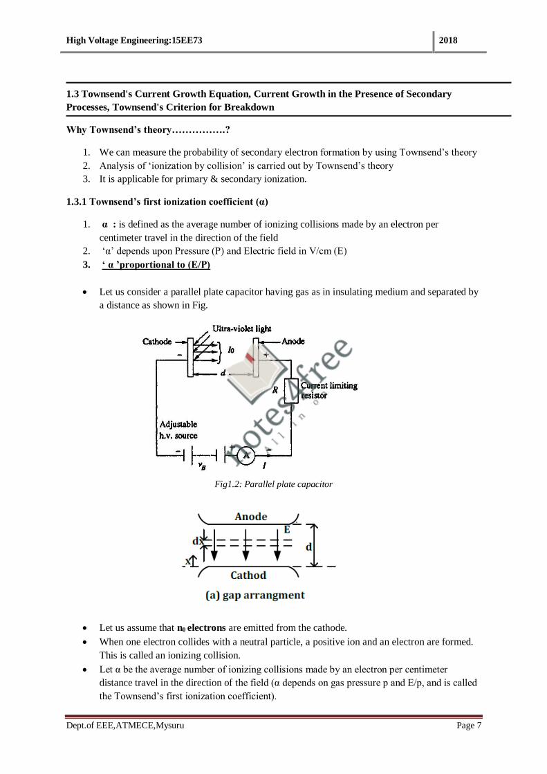
Let us consider a parallel plate capacitor having gas as in insulating medium and separated by
a distance as shown in Fig.
Fig1.2: Parallel plate capacitor
Let us assume that n0 electrons are emitted from the cathode.
When one electron collides with a neutral particle, a positive ion and an electron are formed.
This is called an ionizing collision.
Let α be the average number of ionizing collisions made by an electron per centimeter
distance travel in the direction of the field (α depends on gas pressure p and E/p, and is called
the Townsend’s first ionization coefficient).

High Voltage Engineering:15EE73 2018
Dept.of EEE,ATMECE,Mysuru Page 8
Fig. 1.2 illustrates the breakdown phenomenon of a gas and the growth of current in the gas
which is responsible for breakdown.
The curve has three regions:
1. Ohmic region
2. Saturation region
3. Townsend’s discharge region
Fig 1.2 : Typical current growth curve In Townsend discharge
It is observed from the figure that the current at first increases proportionally with the increases in field
or voltage. This region is called ohmic region.
After this state, a situation comes when current become constant I0 even if voltage is increased. The
constant current I0 is called the saturation current.
At still higher voltage, the current increases exponentially.
High Voltage Engineering:15EE73 2018
Dept.of EEE,ATMECE,Mysuru Page 9
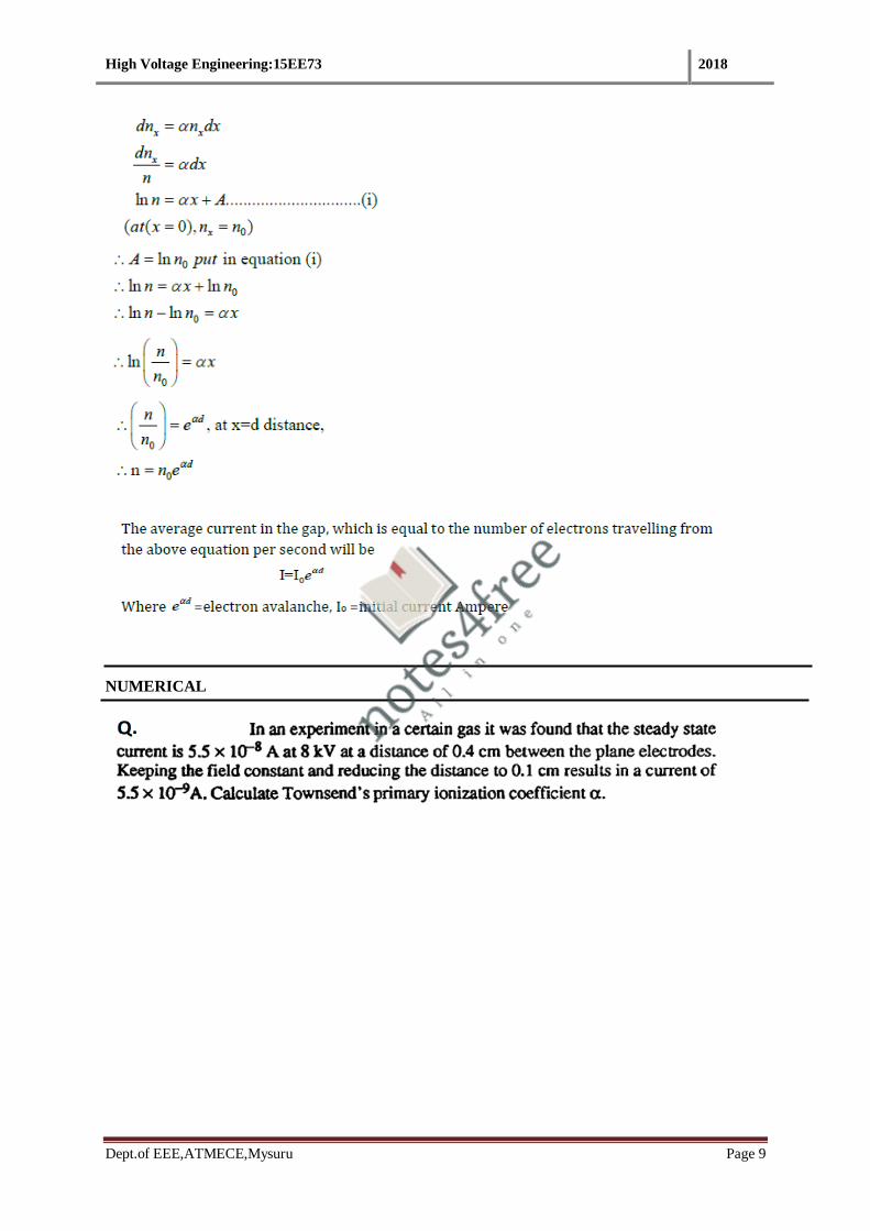
NUMERICAL
High Voltage Engineering:15EE73 2018
Dept.of EEE,ATMECE,Mysuru Page 10
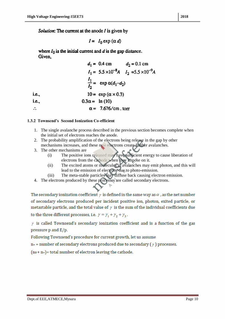
1.3.2 Townsend’s Second Ionization Co-efficient
1. The single avalanche process described in the previous section becomes complete when
the initial set of electrons reaches the anode.
2. The probability amplification of the electrons being release in the gap by other
mechanisms increases, and these new electrons create further avalanches.
3. The other mechanisms are
(i) The positive ions released may have sufficient energy to cause liberation of
electrons from the cathode when they impose on it.
(ii) The excited atoms or molecules in avalanches may emit photon, and this will
lead to the emission of electrons due to photo-emission.
(iii) The meta-stable particles may diffuse back causing electron emission.
4. The electrons produced by these processes are called secondary electrons.
High Voltage Engineering:15EE73 2018
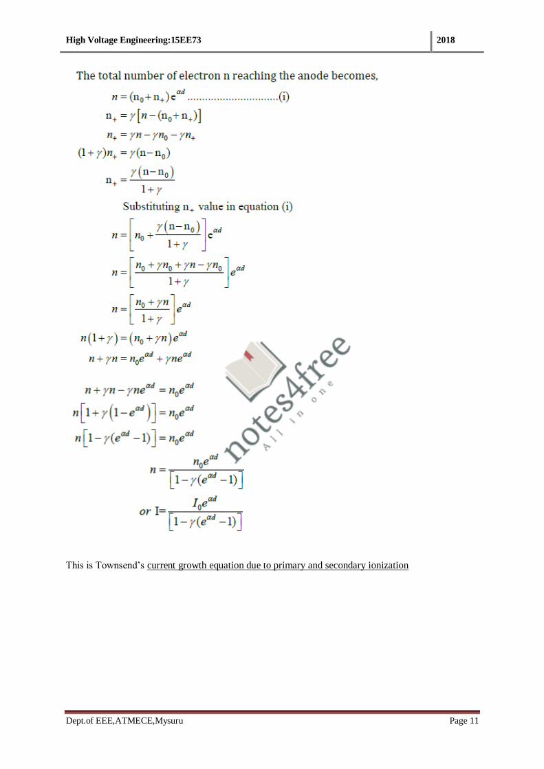
Dept.of EEE,ATMECE,Mysuru Page 11
This is Townsend’s current growth equation due to primary and secondary ionization

High Voltage Engineering:15EE73 2018
Dept.of EEE,ATMECE,Mysuru Page 12
1.3.3 Limitation of Townsend’s theory
Townsend theory or Townsend’s mechanism applied to gas-discharge phenomenon was found to have some drawback or limitations.
(i) First drawback is that according to Townsend’s theory, the current growth occurs as a result of ionization
process only. But in practice, breakdown voltages were found to depend on the gas pressure and the geometry of the gap.
(ii) Secondary, the Townsend’s mechanism predicts the time-lag of the order of 10 -5seconds. While in practice, the breakdown was observed to occur at very short time of the order of 10 -8 sec.
(iii) Townsend’s mechanism predicts the very diffused from of discharge but in practice, it was found to be
filament and irregular.
iv) It is applicable for pd value below 1000 torr-cm.
1.4 Condition for Gaseous dielectric breakdown

High Voltage Engineering:15EE73 2018
Dept.of EEE,ATMECE,Mysuru Page 13
1.5 Breakdown in Electronegative Gases
Electronegative gases are the gases that have similarity towards electrons. When electron
comes into contact with these gas molecules, the gas molecule attracts the electrons and
becomes negative ion.
The gases, which are lacking in one or two electrons in their outer shell are known as
electronegative gases.
The most common attachment processes encountered in gases are :
A simple gas of this types is oxygen. Other gases are Sulphur hexafluoride, Freon, carbon
dioxide, and fluorocarbons.
In this gases, ‘A’ is usually Sulphur or carbon atom, and ‘B’ is oxygen atom or one of the
halogen atoms or molecules.
With such gases, the Townsend current growth equation is modified to include ionization and
attachment.

High Voltage Engineering:15EE73 2018
Dept.of EEE,ATMECE,Mysuru Page 14
1.6 Time Lag of Breakdown
1. Theoretically the mechanism of spark breakdown is considered as a function of ionization
processes under uniform field conditions.
2. In practical engineering designs, the breakdown due to rapidly changing voltage or impulse
voltage is of great importance.
3. Actually there is a time difference in the application of a voltage sufficient to cause
breakdown and the occurrence of breakdown itself. This time difference is called as the time
lag.
4. The Townsend criterion for breakdown is satisfied only if at least one electron is present in
the gap between the electrodes as in the case of applied d.c. or slowly varying (50Hz a.c.)
voltages. This is no difficulty in satisfying this condition.
5. With rapidly varying voltage of short duration (≈10-6 s), the initiatory electron may not be
present in the gap then the breakdown cannot occur due to not available free electron.
i. Statistical time-lag(ts): is defined as the time lapsed between the application of voltage sufficient
to cause breakdown and the appearance of initiating electron is called as statistical time lag.
1. The Statistical time lag depends upon the amount of pre-ionization present in the gap.
2. This in turn depends on the size of the gap and the quantity of radiation that produces the
primary electrons.
3. The techniques generally used for irradiating the gaps include ultraviolet radiation,
radioactive materials and light sources.
ii. Formative time-lag(tf): After the appearance of electron, the time tf required for the ionization
process to develop fully to cause to the breakdown of gap is called as formative time-lag.
The formative time lags depend mostly on the mechanism of the avalanche growth in the gap.
iii. Total time-lag (t): is define as the sum total of Statistical time-lag and formative time-lag T= ts +
tf

High Voltage Engineering:15EE73 2018
Dept.of EEE,ATMECE,Mysuru Page 15
Fig 1.4 : 5Breakdown with a step function voltage pulse
1.7 Streamer or Kanal Mechanism of Breakdown of Spark:
1. The streamer Mechanism of Breakdown is also known as “Kanal” mechanism of breakdown.
2. The Streamer theory removes the limitation and drawbacks of Townsend’s theory.
3. We know that the charges in between the electrodes separated by a distance d increase by a factor
4. eαd when field between electrodes is uniform
5. This is valid only if we assume that the field E0 = V/d is not affected by the space charges of electrons
and positive ions.
6. Whenever the concentration exceeds 108, the avalanche current is followed by steep rise in current and
breakdown of the gap takes place.
7. The weakening of the avalanche at lower concentration and rapid growth of avalanche at higher
concentration have been attributed to the modification of the electric field E0 Due to the space charge
field.
Streamer theory of breakdown for gas or Avalanche breakdown :
1. Avalanche breakdown or streamer breakdown is a phenomenon that can occur in both
insulating and semiconducting materials.
2. It is a form of electric current multiplication that can allow very large currents within
materials & causes dielectric breakdown.
3. Formation of finger like discharge is called as streamer.
“A streamer discharge, also known as filamentary discharge, is a type of transient electrical
discharge. Streamer discharges can form when an insulating medium (for example air) is exposed to a
large potential difference.”
High Voltage Engineering:15EE73 2018
Dept.of EEE,ATMECE,Mysuru Page 16
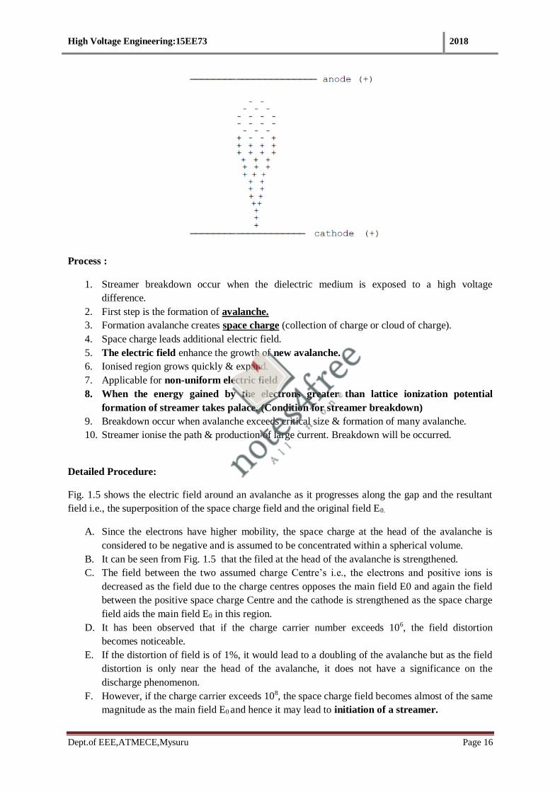
Process :
1. Streamer breakdown occur when the dielectric medium is exposed to a high voltage
difference.
2. First step is the formation of avalanche.
3. Formation avalanche creates space charge (collection of charge or cloud of charge).
4. Space charge leads additional electric field.
5. The electric field enhance the growth of new avalanche.
6. Ionised region grows quickly & expand.
7. Applicable for non-uniform electric field
8. When the energy gained by the electrons greater than lattice ionization potential
formation of streamer takes palace. (Condition for streamer breakdown)
9. Breakdown occur when avalanche exceeds critical size & formation of many avalanche.
10. Streamer ionise the path & production of large current. Breakdown will be occurred.
Detailed Procedure:
Fig. 1.5 shows the electric field around an avalanche as it progresses along the gap and the resultant
field i.e., the superposition of the space charge field and the original field E0.
A. Since the electrons have higher mobility, the space charge at the head of the avalanche is
considered to be negative and is assumed to be concentrated within a spherical volume.
B. It can be seen from Fig. 1.5 that the filed at the head of the avalanche is strengthened.
C. The field between the two assumed charge Centre’s i.e., the electrons and positive ions is
decreased as the field due to the charge centres opposes the main field E0 and again the field
between the positive space charge Centre and the cathode is strengthened as the space charge
field aids the main field E0 in this region.
D. It has been observed that if the charge carrier number exceeds 106, the field distortion
becomes noticeable.
E. If the distortion of field is of 1%, it would lead to a doubling of the avalanche but as the field
distortion is only near the head of the avalanche, it does not have a significance on the
discharge phenomenon.
F. However, if the charge carrier exceeds 108, the space charge field becomes almost of the same
magnitude as the main field E0 and hence it may lead to initiation of a streamer.

High Voltage Engineering:15EE73 2018
Dept.of EEE,ATMECE,Mysuru Page 17
G. The space charge field, therefore, plays a very important role in the mechanism of electric
discharge in a non-uniform gap.
H. This photon falls on the molecules and again electrons are release which is called
photoionization. Photoionization of gas molecules is the secondary mechanism of ionization
responsible for breakdown.
I. On the whole, it is observed that due to (i)Enhancement of field (ii)Primary ionization
(iii) Photoionization
A. Size of the electron avalanche is gradually increased and the avalanches are
transformed into channels of ionization which proceeds towards the anode.
B. Such channels are called the steamer (anode streamer).
C. Finally the gas breakdown, at the moment of breakdown the avalanche has got
specific size which is called critical size of avalanche.
Fig 1.5 : Breakdown with a step function voltage pulse
Fig: 1.6 Formation of secondary avalanches due to photo-ionization

High Voltage Engineering:15EE73 2018
Dept.of EEE,ATMECE,Mysuru Page 18
Streamer breakdown classification:
Positive streamer
1. Low electric field
2. Positive streamers propagate in the opposite direction.
Negative streamer
1. Negative streamers propagate against the direction of the electric field
2. Negative streamers require higher electric fields
Areas of application
1. Ozone production
2. Air purification
3. Plasma medicine
1.8 Paschen's Law
1. Paschen’s theory is one of the most important theories related to breakdown of gaseous
insulating material.
2. It is widely used in the design of extra high voltage equipments.
3. The gas to be used in the apparatus is matched and studied with operating voltage of the
system.
4. The breakdown voltage must be greater than the operating voltage of the system.
Paschen’s Law: The law essentially sates that, at higher pressures (above a few torr) the breakdown
characteristics of a gap are function (generally not linear ) of the product of the gas pressure(p) and
gap length(d), usually written as Vb= f(P.d)
The above relation does not imply that breakdown voltage Vb is directly proportional to product the
product of p and d.
Fig1.7: Vb varies non-linearly with the product Pd

High Voltage Engineering:15EE73 2018
Dept.of EEE,ATMECE,Mysuru Page 19
1. Paschen, a scientist studied the breakdown voltage of various gases between the parallel metal
plates as the pressure & distance where varied.
2. Paschen found that Voltage is a function only of the product of the pressure & gap
length(distance).
3. The equation V= f(pd) is called as Paschen’s law
4. At higher pressure and air gap length, the breakdown voltage is approximately proportional to
product of pressure & air gap.
5. The curve which shows the voltage versus the pressure gap length is called Paschen’s curve.
6. Paschen law will be helpful for finding the minimum breakdown voltage of a gas.
7. The minimum pd value for air is 0.567 and 367V.
8. Application – based on Paschen’s law, we can find the minimum sparking voltage
(Breakdown voltage)of various gas.

High Voltage Engineering:15EE73 2018
Dept.of EEE,ATMECE,Mysuru Page 20
1.8.1 Derive an expression for Paschen’s Law
pd(min) and Vb(min):
1. The Paschen's curve, the relationship between V and pd is shown in above graph for three gases CO2,
air and H2. It is seen that the relationship between V and pd is not linear and has a minimum value for
any gas.
2. This means that a breakdown voltage of a uniform field gap is a unique function of the product of p, the
gas pressure and d, the electrode gap, for a particular gas and for a given electrode material.
The breakdown criterion in gases is given as
Substituting for E in the expressions for a and y and rewriting Equation
Paschen’s curve for different dielectrics
High Voltage Engineering:15EE73 2018
Dept.of EEE,ATMECE,Mysuru Page 21
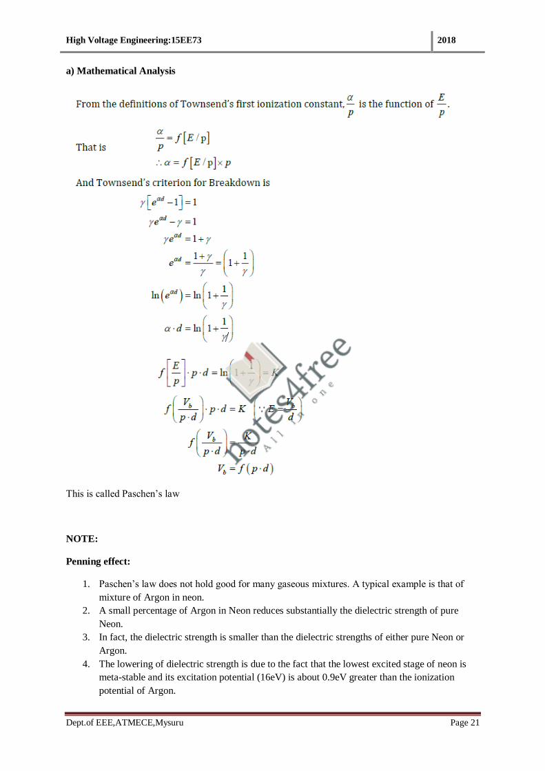
a) Mathematical Analysis
This is called Paschen’s law
NOTE:
Penning effect:
1. Paschen’s law does not hold good for many gaseous mixtures. A typical example is that of
mixture of Argon in neon.
2. A small percentage of Argon in Neon reduces substantially the dielectric strength of pure
Neon.
3. In fact, the dielectric strength is smaller than the dielectric strengths of either pure Neon or
Argon.
4. The lowering of dielectric strength is due to the fact that the lowest excited stage of neon is
meta-stable and its excitation potential (16eV) is about 0.9eV greater than the ionization
potential of Argon.

High Voltage Engineering:15EE73 2018
Dept.of EEE,ATMECE,Mysuru Page 22
5. The meta-stable atoms have a long life in neon gas, and on hitting Argon atoms there is a very
high probability of ionization them.
6. This phenomenon is known as Penning Effect.
1.9 Breakdown in Non-Uniform Fields and Corona Discharges
1. It is an electric discharge mainly occurring at non uniform electric field
2. Visual and audible discharge
3. The corona will occur when the strength of the electric field around a conductor is high
enough to form a conductive region, but not high enough to cause electrical breakdown or
arcing to nearby objects.
4. It is often seen as a bluish (or other color) glow in the air adjacent to pointed metal conductors
carrying high voltages, and emits light by the same property as a gas discharge lamp.
5. Potential difference between two electrodes should be greater than threshold value (30kV).
Corona Discharge:
1. If the electric field is uniform and if the field is increased gradually, just when measurable
ionization begins, the ionization leads to complete breakdown of the gap.
2. However, in non-uniform fields, before the spark or breakdown of the medium takes place,
there are many sign in the form of visual and audible discharges. These discharges are known
as Corona discharges.
3. This phenomenon is always accompanied by a hissing noise, and the air surrounding the
corona region becomes converted into ozone.
4. Corona is responsible for considerable loss of power from high voltage transmission lines,
and it leads to the deterioration of insulation due to the combined action of the bombardment
of ions and of the chemical compounds formed during discharges.
5. Corona also gives rise to radio interference.
6. The voltage gradient required to produce visual a.c. corona in air at a conductor surface,
called the corona inception field, can be approximately given for the case of parallel wires of
radius r as

High Voltage Engineering:15EE73 2018
Dept.of EEE,ATMECE,Mysuru Page 23
Fig. 1.8 shows the corona inception and breakdown voltages of the sphere-plane arrangement. From
the figure, it is clear that—
(i) For small spacing (Zone–I), the field is uniform and the breakdown voltage depends mainly on the
gap spacing.
(ii) In zone–II, where the spacing is relatively larger, the electric field is non-uniform and the
breakdown voltage depends on both the sphere diameter and the spacing. (iii) For still larger spacing.
(iii) at large spacing(zone-III) the field is non-uniform and the breakdown is preceded by corona and
is controlled only by the spacing. The corona inception voltage mainly depends on the sphere
diameter.
Fig 1.8 :Breakdown and corona inception characteristics for spheres of different diameter in Sphere - plane gap geometry

High Voltage Engineering:15EE73 2018
Dept.of EEE,ATMECE,Mysuru Page 24
Results of corona
a. Power loss
b. Hissing noise
c. Ozone formation
d. Chemical activities
Factors affecting corona
a. Air desnsity & Humidity are inversely proportional to corona.
b. Surface conduction is proportional to corona.
Problems associated with corona
a. Ozone (O3) , Nitric acid & Nitrogen oxide (NOx) production
b. Electromagnetic interference
c. Audible noise
d. Insulation losses
1.10 Solid Dielectrics
• Solid dielectrics are commonly used all kinds of electric circuit and devices.
• Provide insulation for current carrying conductors.
Properties of good solid dielectric material
1. Good mechanical strength
2. Free from gaseous inclusion
3. Free from moisture
4. Resistant to thermal and chemical deterioration
5. Low dielectric loss
Types of breakdown mechanism
(a) Intrinsic or ionic breakdown
1. Electronic breakdown
2. Avalanche breakdown
(b) Electromechanical breakdown
(c) Failure due to treeing and tracking
(d) Thermal breakdown
(e) Electrochemical breakdown
(J) Breakdown due to internal discharges

High Voltage Engineering:15EE73 2018
Dept.of EEE,ATMECE,Mysuru Page 25
Types of breakdown mechanism
Intrinsic breakdown
1. Usually a small number of conduction electrons (free electrons) present in the solid dielectric
dielectric material.
2. The following reasons such as
i) Small number of impurities &
ii) Structural imperfection of dielectric material are responsible for intrinsic breakdown.
3. The impurity atoms, or molecules or both act as traps for the conduction electrons up to
certain ranges of electric fields and temperatures.
4. When these ranges are exceeded, additional electrons in addition to trapped electrons are
released, and these electrons participate in the conduction process.
5. Presence of free electrons which are capable of migration through the lattice of the dielectrics.
6. Process will be repeated until the completion of dielectric breakdown of solid dielectric
material.
Types of Intrinsic breakdown
1. Electronic breakdown
2. Avalanche breakdown
(1) Electronic breakdown
1. Due to the presence of large density free electrons in a solid dielectrics
2. Whenever a high voltage is applied, collision between large free electrons will take place.
3. As a result electrons gain energy from the electric field and cross the forbidden energy gap
from the valance to the conduction band.
4. Eventually dielectric breakdown takes place
(2) Avalanche or streamer breakdown
1. Similar to the breakdown in gaseous dielectric
2. Avalanche breakdown or streamer breakdown is a phenomenon that can occur in both
insulating and semiconducting materials.
3. It is a form of electric current multiplication that can allow very large currents within
materials & causes dielectric breakdown.
4. First step is the formation of avalanche.
5. Formation avalanche creates space charge (collection of charge or cloud of charge).
6. Space charge leads additional electric field.
7. The electric field enhance the growth of new avalanche.
8. Ionized region grows quickly & expand.
9. When the energy gained by the electrons greater than lattice ionization potential formation of
avalanche takes palace. (Condition for avalanche breakdown)
10. Breakdown occur when avalanche exceeds critical size & formation of many avalanche,
Breakdown will be occurred
High Voltage Engineering:15EE73 2018
Dept.of EEE,ATMECE,Mysuru Page 26
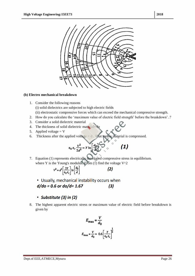
(b) Electro mechanical breakdown
1. Consider the following reasons
(i) solid dielectrics are subjected to high electric fields
(ii) electrostatic compressive forces which can exceed the mechanical compressive strength.
2. How do you calculate the ‘maximum value of electric field strength’ before the breakdown’..?
3. Consider a solid dielectric material
4. The thickness of solid dielectric material=do
5. Applied voltage = V
6. Thickness after the applied voltage = d . That means material is compressed.
7. Equation (1) represents electrically developed compressive stress in equilibrium.
where Y is the Young's modulus. From (1) find the voltage V^2
8. The highest apparent electric stress or maximum value of electric field before breakdown is
given by

High Voltage Engineering:15EE73 2018
Dept.of EEE,ATMECE,Mysuru Page 27
(C) Thermal breakdown
1. Most of the insulation failures in high voltage power apparatus occur due to thermal
breakdown.
2. When an electric field is applied to a dielectric, conduction current, however small it may be,
flows through the material.
3. The current heats up the specimen and the temperature rises.
4. The heat generated is transferred to the surrounding medium by conduction through the solid
dielectric and by radiation from its outer surfaces.
Mathematical expression
• The heat generated under d.c. stress E is given as
Where ‘σ’ is the D.C. conductivity of the specimen.
Under A.C. fields, the heat generated
The heat dissipated (WT) is given by
• Normally Wac or Wdc equals to WT
• Breakdown occur when Wac or Wdc Greater than WT

High Voltage Engineering:15EE73 2018
Dept.of EEE,ATMECE,Mysuru Page 28
c) Breakdown due to treeing & tracking
1. This type of breakdown occurs when a solid dielectric material subjected to electric stress for
a long time.
2. Presence of conducting path inside solid dielectric material due to moisture.
3. A mechanism whereby leakage current passes through the conducting path finally leading to
the formation of a spark.
4. Insulation deterioration occurs as a result of these sparks, sparks erodes the surface, generates
heat & surface becomes dry.
5. The spreading of spark channels said to be tracking, in the form of the branches of a tree is
called treeing
6. As time passes, breakdown channels spread through the insulation in an irregular "tree" like
fashion leading to the formation of conducting channels. This kind of channeling is called
treeing.
7. Usually, tracking occurs even at very low voltages of the order of about 100 V, whereas
treeing requires high voltage.
8. This is a cumulative process, and insulation failure occurs when carbonized tracks bridge the
distance between the electrodes.
9. This phenomena happening the layers of Bakelite, paper, cables and similar dielectrics built
of laminates.

High Voltage Engineering:15EE73 2018
Dept.of EEE,ATMECE,Mysuru Page 29
Breakdown due to treeing & tracking
1. When a dielectric material lies between two electrodes as shown in Fig. There is a possibility
for two different dielectric media, the air and the dielectric, to come in series.
2. The voltages across the two media are as shown (V1 across the air gap, and V2 across the
dielectric). The voltage V1 across the air gap is given as,
How to prevent treeing & tracking??
1. Treeing can be prevented by having clean, dry, and undamaged surfaces and a clean
environment.
2. The materials chosen should be resistant to tracking.
3. Sometimes moisture repellant greases are used. But this needs frequent cleaning and
regressing.
4. Increasing creepage distances should prevent tracking, but in practice the presence of
moisture films defeat the purpose.
5. Usually, treeing phenomena is observed in capacitors and cables, and extensive work is being
done to investigate the real nature and causes of this phenomenon.
Breakdown due to internal discharge
1. Due to voids or cavities present inside the insulating materials.
2. These voids are generally filled with a medium of lower dielectric strength, and the dielectric
constant of the medium in the voids is lower than that of the insulation.
3. Hence, the electric field strength in the voids is higher than that across the dielectric.
4. Therefore, even under normal working voltages the field in the voids may exceed their
breakdown value, and breakdown may occur.

High Voltage Engineering:15EE73 2018
Dept.of EEE,ATMECE,Mysuru Page 30
Numerical
A solid dielectric specimen of dielectric constant of 4.0 shown in the figure has an internal void of
thickness 1 mm. The specimen is 1 cm thick and is subjected to a voltage of 80 kV (rms). If the void
is filled with air and if the breakdown strength of air can be taken as 30 k V (peak)/cm, find the
voltage at which an internal discharge can occur

High Voltage Engineering:15EE73 2018
Dept.of EEE,ATMECE,Mysuru Page 31
1.11 Liquid Dielectrics
Properties of good liquid dielectric material
1. High density
2. High dielectric strength
3. Should free from moisture
4. Should free from oxidation
5. High resistivity
6. High heat transfer characteristics
7. Chemically stable
8. Applications- Transformer oil, Silicon oil, Synthetic hydro carbon(power cable) &
chlorinated hydro carbon
Breakdown in liquid dielectrics
1. Impurities like gas bubbles, suspended particles etc will reason for dielectric breakdown.
2. Breakdown mechanism depends upon nature of electrodes, physical properties of the liquid
dielectrics, presence of impurities & gas present in the liquid
Theories supported for dielectric breakdown in Liquid dielectric material
1. Suspended particle theory
2. Cavitation & bubble mechanism
3. Electro convection breakdown
4. Electronic breakdown
1. Suspended particle theory
1. Commercial liquids will always contain solid impurities like fibers or dispersed solid particles
& gaseous bubbles.
2. Consider the permittivity of liquid dielectrics Ԑ1 & permittivity of solid impurities being Ԑ2.
3. Ԑ2> Ԑ1
4. When the electric field is applied the force is directed towards areas of maximum stress case
of the presence of solid particles like paper (solid impurities) in the liquid.
5. On the other hand, if only gas bubbles are present in the liquid (Ԑ2<Ԑ1).
6. If we consider these impunities (solid or gas) to be spherical particles of radius ‘r’, and if the
applied field is ‘E’ then the particles experience a force ‘F’
7. The process of Liquid dielectric breakdown depends up on the size & number of external
impurities (either solid or gaseous impurities)
8. If the field exceeds the breakdown strength of the liquids, liquid dielectric breakdown will
occur.
9. If the number of impurities present are large, they becomes aligned due to these forces, and
thus form a stable chain bridging the electrode gap causing a breakdown between the
electrodes.

High Voltage Engineering:15EE73 2018
Dept.of EEE,ATMECE,Mysuru Page 32
2. Cavitations (Bubble’s theory) theory
1. Theory states that dielectric strength of liquid dielectric material depends up on hydrostatic
pressure.
2. Hydrostatic pressure proportional to higher electric field strength & it is responsible for
changing the phase of liquid dielectrics & results in liquid dielectric breakdown.
3. A kind of small vapor bubble formed inside the liquid dielectrics reason for dielectric
breakdown.
4. The following reasons responsible for the bubble’s formation in liquid dielectric material -
Gas pockets in the electrode surface - Irregular surface of electrodes - Change in temperature
& pressure - Dissociation of product by electron collision
5. Condition of breakdown- “ Voltage drop along the length of bubble equals to minimum value
of voltage in the Paschen’s curve”.
6. The value of breakdown field is given by
Where σ = surface tension of the liquid, Ԑ1=permittivity of liquid, Ԑ2= permittivity of gaseous
bubble, r=initial radios of gas bubble Vb= Voltage drop in the bubble corresponding to the
minimum value in the pachen’s curve.
1. Breakdown strength depends upon initial size of bubble’s, which influence by hydrostatic
pressure & temperature.
Limitations
• This theory doesn’t mention about the formation of initial bubbles.
• Theoretical & experimental calculation of breakdown strength are different.
3.Electronic breakdown
1. Once the voltage is applied in between two electrodes, electrons are injected to the liquid
2. Electron gains energy from the electric field • Starts the collision process in between other
electrons
3. Electrons are accelerated under electric field & would gain a sufficient energy to knock out an
electron & beginning the process of avalanche.
4. Condition of breakdown is referred as “Threshold condition”

High Voltage Engineering:15EE73 2018
Dept.of EEE,ATMECE,Mysuru Page 33
5. Threshold condition achieved when the energy gained by the electron equals to energy lost
during ionisation. • e*λ*E = C* h *μ C=constant
4. Electro-convection breakdown
1. Breakdown in pure insulating fluid under high voltage
2. Charge carrier injected to liquid surface
3. Resulting the formation of space charge region
4. Increase the columbic force
5. Reason for hydrodynamic instability
6. Formation of convection current
7. The interaction between the space charge & the electric field give rise to eddy motion of
liquid.
Conclusion
1. It is clear that no single theory can explain all the experimental observation satisfactorily.
2. All the above theories do not consider dependence of breakdown strength on the gap length.
3. Experimental evidence showed that the breakdown strength of liquids depends on the gap
length.
Note : Power law
1. The above equation is termed as ‘power law’ equation.
2. The breakdown voltage depends on nature of voltage, mode in which the voltage is applied,
Gap distance between electrodes & time of application.
Numerical

High Voltage Engineering:15EE73 2018
Dept.of EEE,ATMECE,Mysuru Page 34
Note: Solve all numericals solved in class
Course Outcome
At the end of the course the student will be able to: 1. Explain conduction and breakdown phenomenon in gases, liquid dielectrics and in solid dielectrics.

High Voltage Engineering 2018
Department of EEE,ATMECE,Mysuru Page 1
MODULE -2 Generation of High Voltages and Currents
Syllabus
2.1 Generation of High Direct Current Voltages
2.2 Generation of High Alternating Voltages
2.3 Generation of Impulse Voltages
2.4 Tripping and Control of Impulse Generators.
2.5 Generation of Impulse Currents
Course Objectives
To discuss generation of high voltages and currents and their measurement
2. Introduction
Need for HV Generation
Importance of High voltage DC & AC: High voltage dc require for industry, medical sciences,
HVDC transmission etc.
Applications of high voltage DC: Electrostatic precipitator (EPS) in thermal power plant for
the ash handling unit, electrostatic paint, cement industry etc.
Applications of high voltage AC: Power transmission.
2.1 Generation of High voltage DC
1. Rectifier circuits
2. Van de Graff generators
3. Cock croft- Walton type high voltage DC set
1. Rectifier circuits for producing high DC voltages from AC sources.
(a) Half wave rectifiers.
(b) Full wave rectifiers.
(c) Voltage doubler type rectifiers.

High Voltage Engineering 2018
Department of EEE,ATMECE,Mysuru Page 2

High Voltage Engineering 2018
Department of EEE,ATMECE,Mysuru Page 3
Fig2.1: 1. AC input voltage waveform 2.AC output voltage waveform without condenser filter
3.AC Output voltage waveform with condenser filter
2.1.1 Van de Graff generators
It is a type of electrostatic generator
It generates high potential differences
Then the generated potential differences are used to speed up the particles like ions etc. So it
is a “particle accelerator”
Application: Nuclear physics experiments
The potential difference achieved in modern Van de Graaff generators can reach 5 megavolts.
A Van de Graaff generator operates by transferring electric charge from a moving belt to a
terminal.
The high voltages generated by the Van de Graaff generator can be used for accelerating
subatomic particles to high speeds, making the Van de graaff generator a useful tool for
fundamental Nuclear physics research.
Working of the generator is based on two principles:
1. Discharging action of sharp points, ie., electric discharge takes place in air or gases readily, at
pointed conductors.
2. If the charged conductor is brought in to internal contact with a hollow conductor, all of its
charge transfers to the surface of the hollow conductor no matter how high the potential of the
latter may be.
Applications
1. Accelerating electrons to sterilize food and process materials,
2. Accelerating protons for nuclear physics experiments,
3. Driving X-ray tubes, etc.

High Voltage Engineering 2018
Department of EEE,ATMECE,Mysuru Page 4
Construction
1. A simple Van de Graaff-generator consists of a belt of silk, or a similar flexible dielectric
material, running over two metal pulleys etc
2. The generator is usually enclosed in an earthed metallic cylindrical vessel and is operated
under pressure or in vacuum.
3. Charge is sprayed on to an insulating moving belt from corona points
4. Require the potential of 10 to 100 kV
5. The belt is driven by an electric motor at a speed of 1000 to 2000 rpm
6. Potential of high voltage electrode rises in the rate of
7. The shape of electrodes are spherical
8. The charging of the belt is done by the lower spray points which are sharp needles and
connected to a DC source of about 10 to 100 kV, so that the corona is maintained between the
moving belt and the needles.
9. Belt has self charging system
2.1.2Cock croft Walton type high voltage DC set.
1. Cascaded voltage multiplier circuits (Voltage Doubler circuit) for higher voltages are
cumbersome(difficult) and require too many supply and isolating transformers.
2. It is possible to generate very high DC voltages from single supply transformers by extending
the simple voltage doubler circuits.
3. This is simple and compact when the load current requirement is less than one milli ampere,
such as for cathode ray tubes, etc.
High Voltage Engineering 2018
Department of EEE,ATMECE,Mysuru Page 5
4. Valve type pulse generators may be used instead of conventional AC supply.
5. The circuit becomes compact
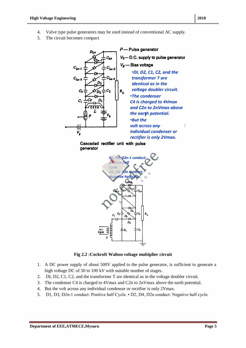
Fig 2.2 :Cockroft Walton voltage multiplier circuit
1. A DC power supply of about 500V applied to the pulse generator, is sufficient to generate a
high voltage DC of 50 to 100 kV with suitable number of stages.
2. DI, D2, C1, C2, and the transformer T are identical as in the voltage doubler circuit.
3. The condenser C4 is charged to 4Vmax and C2n to 2nVmax above the earth potential.
4. But the volt across any individual condenser or rectifier is only 2Vmax.
5. D1, D3, D2n-1 conduct: Positive half Cycle. • D2, D4, D2n conduct: Negative half cycle.

High Voltage Engineering 2018
Department of EEE,ATMECE,Mysuru Page 6
1. Calculation of output voltage
The pulses generated in the anode circuit of the valve P are rectified and the voltage is
cascaded to give an output of across the load RL.
A trigger voltage pulse of triangular waveform (ramp) is given to make the valve switched on
and off.
Ripple content & Voltage drop in cock croft- Walton type dc set
2.Calculation of ripple voltage
3. Calculation of % ripple
4. Calculation of voltage regulation
5. Optimum number of stages for minimum voltage drop
1. In addition to the ripple δV, there is a voltage drop Δv which is the difference between the
theoretical no load and the on load voltage.

High Voltage Engineering 2018
Department of EEE,ATMECE,Mysuru Page 7
2. optimum number of stages for the minimum voltage drop may be expressed as
Current and voltage waveforms of cock croft- Walton type high voltage DC Set
Ripple content & Voltage drop in cock croft- Walton type dc set

High Voltage Engineering 2018
Department of EEE,ATMECE,Mysuru Page 8
2.1.3.Numerical on Cockroft Walton type high voltage DC set

High Voltage Engineering 2018
Department of EEE,ATMECE,Mysuru Page 9
2.2 Generation of HV AC Voltage
Need for Cascade transformer connection
1. When test voltage requirements are less than about 300 kV, a single transformer can be used
for test purposes.
2. The impedance of the transformer should be generally less than 5%
3. Transformer must be capable of giving the short circuit current for one minute or more
depending on the design.
4. Third winding known as meter winding is provided to measure the output voltage.
5. For higher voltage requirements, a single unit construction becomes difficult and costly due
to insulation problems.
6. Transportation and arranging of large transformers become difficult.
7. These drawbacks are overcome by series connection or cascading of the several identical
units of transformers, wherein the high voltage windings of all the units effectively come in
series.
Schematic diagram of cascade transformer for HVAC generation
1. The first transformer is at the ground potential along with its tank.
2. The second transformer is kept on insulators and maintained at a potential of V2, the output
voltage of the first unit above the ground.
3. The high voltage winding of the first unit is connected to the tank of the second unit.
4. The low voltage winding of this unit is supplied from the excitation winding of the first
transformer, which is in series with the high voltage winding of the first transformer at its
high voltage end.
5. The rating of the excitation winding is almost identical to that of the primary or the low
voltage winding

High Voltage Engineering 2018
Department of EEE,ATMECE,Mysuru Page 10
6. Supply to the units can be obtained from a motor-generator set or through an induction
regulator for variation of the output voltage.
7. Isolating transformers IS1,IS2 and IS3 & are 1:1 ratio transformers
8. They are insulated to their respective tank potentials and are meant for supplying the
excitation for the second and the third stages at their tank potentials
9. Power supply to the isolating transformers is also fed from the same AC input.
Advantages of cascade connection
1. Natural cooling is sufficient
2. Transformers are light and compact
3. Ease of transportation & assembly
4. Construction is similar to the isolating transformer & cascaded unit
5. Either star or delta connection are possible
Draw backs
1. More space requirement and expensive
2.2.1 Resonant Circuit
The resonance principle of a series tuned L-C circuit can be made use of to obtain a higher voltage
with a given transformer.

High Voltage Engineering 2018
Department of EEE,ATMECE,Mysuru Page 11
Basic principle of Resonant circuit
2.2.2 Resonant Transformers
1. resonant transformer, an electrical component which consists of two high Q coils wound on
the same core with capacitors connected across the windings to make two coupled LC circuits.
2. Resonant transformer is one of the best choice for high voltage generation which operates on
resonance phenomenon (XL = Xc).
3. In resonance condition, the current through test object is very large and that is limited only
by the resistance of the circuit.
4. The waveform of the voltage across the test object will be purely sinusoidal.

High Voltage Engineering 2018
Department of EEE,ATMECE,Mysuru Page 12
Applications of Resonant Transformer:
1. This principle is utilized in testing at very high voltages and on occasions requiring large
current outputs such as cable testing , dielectric loss measurements, partial discharge
measurements, etc.
1. The equivalent circuit of HV testing circuit consists of a)leakage reactance of the winding,
b)winding resistance, c)magnetizing reactance, d)shunt capacitance across the output
2. It is possible to have a series resonance at power frequency w, if
3. During the resonance condition current in the test object is very large and is limited only by
the resistance of the circuit.
4. The magnitude of the voltage across the capacitance C of the test object will be
5. Q factor of the circuit and gives the magnitude of the voltage multiplication across the test
object under resonance conditions.
6. The input voltage required for excitation is reduced by a factor 1/2, and the output kVA
required is also reduced by a factor 1/Q.
7. The secondary power factor of the circuit is unity.

High Voltage Engineering 2018
Department of EEE,ATMECE,Mysuru Page 13
1. A voltage regulator of either the auto-transformer type or the induction regulator type is
connected to the supply mains.
2. The secondary winding of the exciter transformer is connected across the H.V reactor, L, and
the capacitive load C.
3. The inductance of the reactor L is varied by varying its air gap and operating range is set in
the ratio 10 : 1.
4. Capacitance C comprises of the capacitance of the test object, capacitance of the measuring
voltage divider, capacitance of the high voltage bushing etc.
5. The Q-factor obtained in these circuits will be typically of the order of 50.
Advantages of series resonant circuit
1. It gives an output of pure sine wave.
2. Power requirements are less (5 to 10% of total kVA required).
3. No high-power arcing and heavy current surges occur if the test object fails, as resonance
ceases at the failure of the test object.
4. Cascading is also possible for very high voltages.
5. Simple and compact test arrangement.
6. No repeated flashovers occur in case of partial failures of the test object and insulation
recovery
Disadvantages of series resonant circuit
1. Requirements of additional variable chokes capable of withstanding the full test voltage and
the full current rating
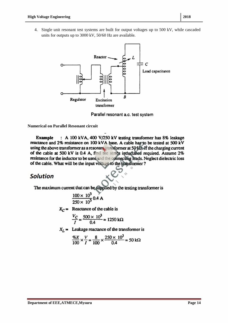
2.2.3 Parallel Resonant Transformer
1. In the parallel resonant mode the high voltage reactor is connected as an auto-transformer and
the circuit is connected as a parallel resonant circuit.
2. The advantage of the parallel resonant circuit is that more stable output voltage can be
obtained along with a high rate of rise of test voltage.
3. Independent of the degree of tuning and the Q-factor.
High Voltage Engineering 2018
Department of EEE,ATMECE,Mysuru Page 14
4. Single unit resonant test systems are built for output voltages up to 500 kV, while cascaded
units for outputs up to 3000 kV, 50/60 Hz are available.
Numerical on Parallel Resonant circuit
High Voltage Engineering 2018
Department of EEE,ATMECE,Mysuru Page 15
2.2.4 Tesla coil
1. Tesla coil is an electrical resonant transformer circuit designed by inventor Nikola Tesla.
2. It is Used to generate or produce high voltage, low current & high frequency AC electricity.
3. High frequency transformer is required.
4. The commonly used high frequency resonant transformer is the Tesla coil.
5. Tesla coil is a doubly tuned resonant circuit.
6. The primary voltage rating is 10 kV and the secondary may be rated to as high as 500 to 1000
kV.
7. Output frequency range: 50kHz to 1 MHz.
8. Damped oscillations can be obtained by using Tesla Coil.
Applications:
1. X-ray generation, experiment in electrical Lighting etc

High Voltage Engineering 2018
Department of EEE,ATMECE,Mysuru Page 16
1. The primary is fed from an AC supply through the condenser C1.
2. A spark gap G connected across the primary is triggered at the desired voltage V, which
induces high self excitation in the secondary.
3. Spark gap G act as a switch of the circuit.
4. The primary and the secondary windings (L1 and L2) are wound on an insulated former with
no core (air-cored) and are immersed in oil. The windings are tuned to a frequency of 10 to
100 kHz by means of the condensers C1 and C2.
5. The output voltage V is a function of the parameters LI, L2, C1, C2 and the mutual
inductance M.
6. Usually, the winding resistances will be small and contribute only for damping of the
oscillations.

High Voltage Engineering 2018
Department of EEE,ATMECE,Mysuru Page 17
1. A more simplified analysis for the Tesla coil may be presented by considering that the energy
stored in the primary circuit in the capacitance C1 is transferred to C2 via the magnetic
coupling.
2. If W1 is the energy stored in C1 and W2 is the energy transferred to C2 and if the efficiency
of the transformer is η, then
Advantages of Tesla coil
1. The absence of iron core in transformers and hence saving in cost and size.
2. pure sine wave output ( Less wave form distortion).
3. Slow build-up of voltage over a few cycles and hence no damage due to switching surges
4. Uniform distribution of voltage across the winding coils due to subdivision of coil stack into a
number of units.
2.3 Generation of Impulse Voltages
What is Impulse Voltage
“Impulse voltage is a unidirectional voltage with no appreciable oscillation. It rises rapidly to a maximum value
and falls more or less rapidly to zero.”
A unidirectional voltage that rapidly rises to a peak value and then drops to zero more or less rapidly. Also
known as pulse voltage.
Why Impulse Voltage?
To study the effect of transient over voltages generated by lightning or switching operations on the
system.

High Voltage Engineering 2018
Department of EEE,ATMECE,Mysuru Page 18
Representation of Impulse Wave
t0 t1 t2 t3
Wave front = 1.5*(t2-t1)
Wave tail = t3-t0
t2 is the time taken to reach 90% of peak value
t1 is the time taken to reach 10% of peak value
a) Impulse Voltage
1. Maximum value is called peak value of impulse voltage.
2. If an impulse voltage develops without causing flashover or puncture is called full impulse voltage.
3. Due to flash over or puncture sudden collapse of impulse voltage will occur and it is called as chopped
impulse voltage.
b) Wave front & Wave tail
A full impulse voltage consists of both wave front and wave tail.
1. Wave front- Time taken by the wave to reach its maximum value starting from zero value.
Since it is difficult to identify the wave front ,Wave front is considered as 1.5 times (t2-t1)
Where t2 is the time taken to reach 90% of peak value
t1 is the time taken to reach 10% of peak value
(t2-t1) is about 80% of wave front time
2. Wave tail- Time measured between the nominal starting point t0 and the point on the wave tail where
the voltage is 50% of peak value.
wave tail time (t3-t0)
Part of a signal-wave envelope (in time or distance) between the steady-state value (or crest)
and the end of the envelope.
c) Standards for impulse voltage
Three standards
1. BSS & ISS standard
2. American Standard Association
3. IEC standard
1. BSS and ISS standard

High Voltage Engineering 2018
Department of EEE,ATMECE,Mysuru Page 19
Standard wave shape specified (1/50) microseconds wave.
i.e a wave front of 1 micro second and wave tail of 50 micro seconds.
Tolerance is not more than +50% or -50% on the duration of the wave front.
20% on the time to half value on the wave tail is allowed.
Complete specification of the wave is 100kV, (1/50) microseconds , where 100kV is the peak value of
the wave
2. American Standard Association
Wave shape recommended by American standard is 1.5/40 microseconds.
Permissible variation 0.5 microseconds on the wave front and +10 or -10 microseconds for wave tail.
The wave front time is taken as 1.67 times the time taken by the wave to rise from 30% to 90% of its
peak value.
Wave tail time is computed same as that of BSS and ISS standard
3. IEC (International Electro technical Commission)
The standard impulse wave shape belonging to 1.2/50μs.
Should withstand higher voltage (above 220kV).
d) Important Definitions Related to Impulse Voltage (Types of impulse Voltage)
1. Chopped wave
If an impulse voltage is applied to a piece of insulation a flash over or puncture occurs and sudden
collapse of impulse voltage is called chopped wave.
If the chopping takes place front part of the wave is called front chopped wave
2. Impulse puncture voltage
Peak value of impulse voltage which cause the puncture of the material.
3. Impulse flash over voltage
When impulse voltage applied to the insulating material flash over may or may not occur.
If the flashover occurs more than 50% of number of applications, then it is called as impulse flash over
voltage.
Impulse flash over voltage depends polarity, duration of wave front & wave tail and nature of material.

High Voltage Engineering 2018
Department of EEE,ATMECE,Mysuru Page 20
IMPULSE GENERATOR
2.3.1 Analysis of single stage impulse generator-expression for Output impulse voltage
“An impulse generator is an electrical apparatus which produces very short high-voltage or
high-current surges”
It can be classified into two types
a) Impulse voltage generators
b) Impulse current generators.
Basic impulse generator
a) Why impulse Generator
1. Impulse generator produces high impulse voltage.
2. High impulse voltages are used to test the strength of electric power equipment
against lightning and switching surges.
3. Steep-front impulse voltages are sometimes used in nuclear physics experiments.
4. High impulse currents are needed for tests on equipment such as lightning arresters.
5. Fuse testing
6. Technical applications such as lasers, thermonuclear fusion, and plasma devices.

High Voltage Engineering 2018
Department of EEE,ATMECE,Mysuru Page 21
b) Basic Impulse Generator
1. An impulse generator essentially consists of a capacitor which is charged to the
required voltage and discharged through a circuit.
2. The circuit parameters can be adjusted to give an impulse voltage of the desired shape.
3. Cs is charged from a dc source until the spark gap G breaks down.
4. The voltage is then impressed upon the object under test of capacitance Cb.
5. The wave shaping resistors Rd and Re control the front and tail of the impulse
voltage available across Cb respectively.
6. c)Overall the wave shape is determined by the values of the generator capacitance
(Cs) and the load capacitance (Cb), and the wave control resistances Rd and Re.
7. The output voltage waveform can be defined by
Where, v(t) instantaneous output voltage, Vo DC charging voltage, , roots of the
characteristics equation, which depends on the parameters of the generator. Where
c) Classification of Impulse Voltage Generator
1. Single Stage Impulse Generator
2. Multi Stage Impulse Generator
d) (Marx generator)
Single stage Impulse Generator
Fig: Single stage Impulse Generator Circuit
1. The spark gap act as voltage limiting & voltage sensing switch.
2. The apparatus which produces the required voltages is the impulse generator.

High Voltage Engineering 2018
Department of EEE,ATMECE,Mysuru Page 22
3. In high voltage engineering, an impulse voltage is normally a unidirectional voltage
which rises quickly without appreciable oscillations, to a peak value and then falls
less rapidly to zero.
Importance of each elements in impulse generator circuit
1. Capacitor (C1)-
C1 is the capacitance of generator charged from a dc source to a suitable voltage.
It will discharge through the space gap.
If the generator is single stage C1 is enough.
In the case of multistage impulse generator group of capacitor connected in parallel and
discharged in series.
2. Inductor (L1)
It is used for the inductance of the generator.
The leads of inductor is connecting to the generator.
It consists of Small value.
3. Resistor (R1)
Used for Damping purpose
For Output voltage / Output waveform control.
4. L3 and R3
These are external elements
connected to the generator for the waveform control/shape
5. R2 and R4
To Control the waveform duration -R4 serve as a potential divider .
6. C2 and C4
Capacitance to the earth of high voltage components and leads.
7. C4
Includes the capacitance of the test object -load capacitance
Hold the voltage to produce required value of wave shape.
8. L4
Inductance of test object
Influence the waveform
9. Grounding

High Voltage Engineering 2018
Department of EEE,ATMECE,Mysuru Page 23
One terminal of impulse generator is solidly grounded.
The polarity of output voltage can be changed by changing the polarity of dc charging
voltage .
Performance parameters of single stage impulse generator
1. Efficiency
2. Impulse energy transformed during a discharge is given by
3. The minimum value of generator capacitance is given by
Equivalent circuits of single stage Impulse Generator
• Evaluation & analysis is easy as compared to main circuit.
Note: Do refer text book of M S Naidu & V Kamaraju – page no 172 for more information

High Voltage Engineering 2018
Department of EEE,ATMECE,Mysuru Page 24
e) Drawbacks of single stage impulse generator
1. Physical size of the circuit elements are very large.
2. Large size of sphere.
3. High dc charging voltage is required.
4. Suppression of corona is difficult.
5. Switching of very high voltage with the spark gap is difficult.
Multistage Impulse Generator
2.3.2 Multistage impulse generator working of Marx impulse
Introduction
• To obtain higher and higher impulse voltage.
• In 1923 E. Marx suggested a multiplier circuit which is commonly used to obtain
impulse voltage with as high a peak value as possible for a given charging dc voltage.
• Depending upon the charging voltage available and output voltage required “the
number of identical impulse capacitors are charged in parallel and then discharged in
series”.
• Obtain total charging voltage multiplied with number of stages.
Why Multistage Impulse Generator?
A single capacitor C1 is may be used for voltages up to 200 kV. Beyond this voltage, a single
capacitor & charging unit may be too costly & the size becomes very large
Schematic Diagram of Multistage Impulse Generator

High Voltage Engineering 2018
Department of EEE,ATMECE,Mysuru Page 25
Schematic Diagram of Multistage Impulse Generator (Modified)
Rs is a charging resistance to limit the charging current.
1. The generator capacitance C is chosen such that the product of CRs is about 10s to 1
min.
2. The gap spacing is chosen such that the breakdown voltage of the gap G is greater
than the charging voltage V.
3. All the capacitance are charged to the voltage V in about 1 minute.
4. Charging time constant=CRs (in seconds)
5. Discharging time constant = CR1/n (in micro seconds) , where n is the number of
stages.
A 16 stage Multistage Impulse Generator having a stage capacitance of 0.280μF And
maximum charging voltage 300kV .
High Voltage Engineering 2018
Department of EEE,ATMECE,Mysuru Page 26
The height of the generator will be about 15m.
Area = 3.25m x 3.00 m
2.3.1.1Construction of Multistage Impulse Generator
1. Require a dc power supply for charging the impulse capacitance C1 of the generator.
2. Supply consists of step up transformer and rectifier.
3. The value of resistor should be constant & never vary with external factors.
4. Non-inductive wire wound resistors are commonly used.
5. Resistors which will be used for the construction for multistage impulse generator
flexible to replace.
6. Oil paper insulated capacitor having high rate of discharge are normally employed
and reason for reduced size of capacitor.
7. The sphere gap adjusted by a remotely controlled motor conjunction with indicator.
8. Chimney provided with dust free and dry air.
9. A series protective resistance should be included in this earthing device to avoid too
high discharge current.
10. Charging resistors are fixed at sphere column.
11. Front and tail resistor fixed to the generator frame.
12. All the leads and electrodes should dimensioned properly to avoid corona discharge.
2.3.1.2 Components of a multistage impulse Generator
A Multistage impulse generator requires several components parts for Flexibility &
production of the required wave shape.
1. DC Charging set
2. Charging Resistors
Non inductive high value of resistance about 10 to 100k.Ω
Each resistance will be designed to have a maximum voltage between 50 and 100kV.
3. Generator Capacitors and spark gap
Capacitor designed for several charging and discharging operations.
Capacitors will be capable of having 10kA of current.
Spark gaps will be usually spheres or hemispheres of 10 to 25 cm diameter.
4. Wave-shaping Resistors and Capacitors -Non inductive wound type -Capable of
discharging 1000A current -50 to 100kV max. designed voltage

High Voltage Engineering 2018
Department of EEE,ATMECE,Mysuru Page 27
Load capacitance will be 1 to 10nF
5. Triggering System
Contains trigger spark gap to cause spark breakdown of the gaps.
6. Voltage Dividers
Resistor type or damped capacitor type
oscilloscope with recording arrangement are provided for measurement of voltage
across test object
7. Gas insulated impulse generator
Above 4MV impulse generator, tall & large space requirement
4.8MW- nearly 30m height
N2, compressed gas and SF6 will provide proper insulation.
2.4 Triggering and Synchronization of the impulse Generator
Why triggering & synchronization?
Control for charging process of impulse generator.
To integrate the measuring devices.
Chopping gap control.
CRO is used for measuring and studying the effect of impulse wave on the
performance of the insulation of the equipment.
Impulse waves are of shorter duration.
It is necessary that operation of the generator and the oscillograph should be
synchronized accurately.
Time sweep circuit is main part of oscillograph
The time sweep circuit of the oscillograph should be initiated at the time slightly
before the impulse wave reaches the deflecting plates.
The impulse generator drives both sweep and triggering circuits.
The sweep circuit operating first , triggering circuit works after 0.1 to 0.5
microseconds.
Triggering -3 Stages
1. Fix the gap distance between the spheres and increase the stage applied dc voltage till
the flashover occurs.
2. Set the gap distance between the spheres large enough apply a desired voltage across
them and then reduce the gap distance till flashover takes place.
3. Fix both, the desired stage voltage and corresponding gap distance within prescribed
limits. Then apply the trigger pulse to the trigatron on the first stage.

High Voltage Engineering 2018
Department of EEE,ATMECE,Mysuru Page 28
Triggering and Synchronization of the impulse Generator
Two methods are available
1. Three electrode gap arrangement
2. Trigatron gap
2.4.1 Triggering of impulse generator by three electrode gap arrangement
Triggering of impulse generator by
(i) Three electrode gap arrangement
1. ‘Three electrode gap arrangement ‘ is one of the method for triggering and
synchronization of impulse generator.
2. The spacing between 2 spheres is adjusted so that two series gap are able to
withstand charging voltage of impulse generator.
3. Central sphere is called control sphere.
4. A high resistance is connected between the outer sphere and its centre point is
connected to control sphere.
5. The voltage between outer sphere is equally divided between two sphere gap
To test the dielectric breakdown strength of three sphere gap arrangement
1. First impulse generator is to be charged to a voltage which is slightly less than the
breakdown voltage of the gap.

High Voltage Engineering 2018
Department of EEE,ATMECE,Mysuru Page 29
2. Apply an impulse wave of either polarity & peak voltage not less than (1/5) th of
charging voltage to the control sphere.
3. Check whether the dielectric breakdown has occurred or not.
Operation of three sphere gap arrangement
• Two ‘three sphere gap arrangement’ is included in the synchronization &
triggering circuit
1. Three sphere gap arrangement’
1. The switch‘s’ is closed which initiate the sweep circuit of the oscillograph.
2. The same impulse is applied to the thyratron tube.
3. The inherent time delay of thyratron ensure sweep circuit operate first before the
starting of high impulse wave.
4. We can be able to create further delay by using Capacitance-Resistance (R1C1)
circuit.
5. The tripping impulse is applied through capacitor C2.
6. During charging period the voltage across thyratron is about +20kV.
2. Trigatron gap
1. A device, known as "Trigatron", is used to control the flash over at the spark
gaps in order to get a desired magnitude of the output voltage repeatedly.
2. Function- used as ‘First gap of impulse generator’
3. "Trigatron", consists essentially of three-electrodes.
4. Three electrodes are
1. High voltage electrode is a sphere- indication of HV
2. Earthed electrode is also a sphere. The spherical configuration gives homogeneous
field.
3. Metal rod electrode/ Trigger electrode be the third electrode
5.5 Diagram for “Trigatron spark gap”

High Voltage Engineering 2018
Department of EEE,ATMECE,Mysuru Page 30
a) Construction of “Trigatron spark gap”
1. A small hole is drilled into earth electrode into which metal rod projects (trigger rod).
2. The annular gap between the rod and the surrounding hemisphere is 1 mm.
3. A glass tube is fitted over rod electrode.
4. The potential of metal electrode and earth electrodes are same.
5. Both are connected through a high resistance.
6. Tripping pulse or control pulse applied between metal and earth electrodes.
7. When the tripping pulse is applied, main field is distorted.
8. Reason for dielectric breakdown.
b)Tripping circuit of trigatron

High Voltage Engineering 2018
Department of EEE,ATMECE,Mysuru Page 31
c) Operation of Tripping circuit of trigatron
• The capacitor C1 is charged through high resistance R1
• Switch S is closed
• A pulse is applied to a sweep circuit of the oscillograph through the capacitor C3
• Same time capacitor C2 is charged
• Triggering pulse is applied through trigger electrode (metal rod electrode)
• The requisite delay in triggering the generator can be provide by R2 and C2
• The residual charge on the C2 can discharged through R2
• Now a day’s laser is used for tripping the spark gap
• The trigatron also has a phase shifting circuit associate with the synchronization of
initiation time with external Alternating voltage.
• Design is to prevent the overcharging of capacitor
• An indicating device shows whether the generator is going to fire properly or not.
2.4.1 Generation of switching surges/ switching impulse voltage
• Switching surges has an important role in the design of insulation for extra high
voltage transmission line (EHV) & power systems.
• Switching surge is a short duration transient voltage produced in the system due to
sudden opening or closing of switch or circuit breaker.
• Switching surges may be produced due to arcing at faulty power systems.
• The transient voltage may be oscillatory wave or damped oscillatory wave having
frequency of a few hundred Hz to a few kilo Hz.
• Wave front time= 0.1 to 10ms
• Wave tail time ~ 1ms
• Switching surges contain higher energy than lightning impulse voltage.

High Voltage Engineering 2018
Department of EEE,ATMECE,Mysuru Page 32
• Types of circuit produced switching surges
Modified impulse generator for long Power transformer or testing transformer
duration wave shapes
2.5 Impulse Current Generation
A high impulse current generator consists of large number of capacitor connected in parallel
to a common discharge path. i.e by using ‘capacitor bank’.
• The generation of impulse current waveforms of high magnitude (nearly 100 KA) find
applications like
1. test work
2. basic research on non-linear resistors -electric arc studies
3. electric plasma state
a) Definition of impulse current waveforms
• The wave shapes used in testing surge diverters are (4/10 micro seconds-wave front)
and (8/20 micro seconds –wave tail).
• Tolerance allowed in between +10% and -10%.
• Wave shapes are normally rectangular shape.

High Voltage Engineering 2018
Department of EEE,ATMECE,Mysuru Page 33
b) Circuit producing impulse current wave

High Voltage Engineering 2018
Department of EEE,ATMECE,Mysuru Page 34
Number of capacitors connected in parallel & discharged in parallel in the circuit.
In order to minimize the value of inductance capacitance are subdivided into smaller
units.
c) Components
1. DC charging unit giving variable voltage to capacitor bank.
2. Additional air core inductor having high current value.
3. Oscillograph- measurement purpose.
4. Triggering units & spark gap.
d) Generation of Rectangular Current Pulses
1. The generation of rectangular current pulse can be done by ‘discharging a pulse
network or cable previously charged’
2. To produce a rectangular pulse a coaxial cable of surge impedance Z0 is used.
Course Outcomes
Explain generation of high voltages and currents and Discuss measurement techniques for high voltages and currents.
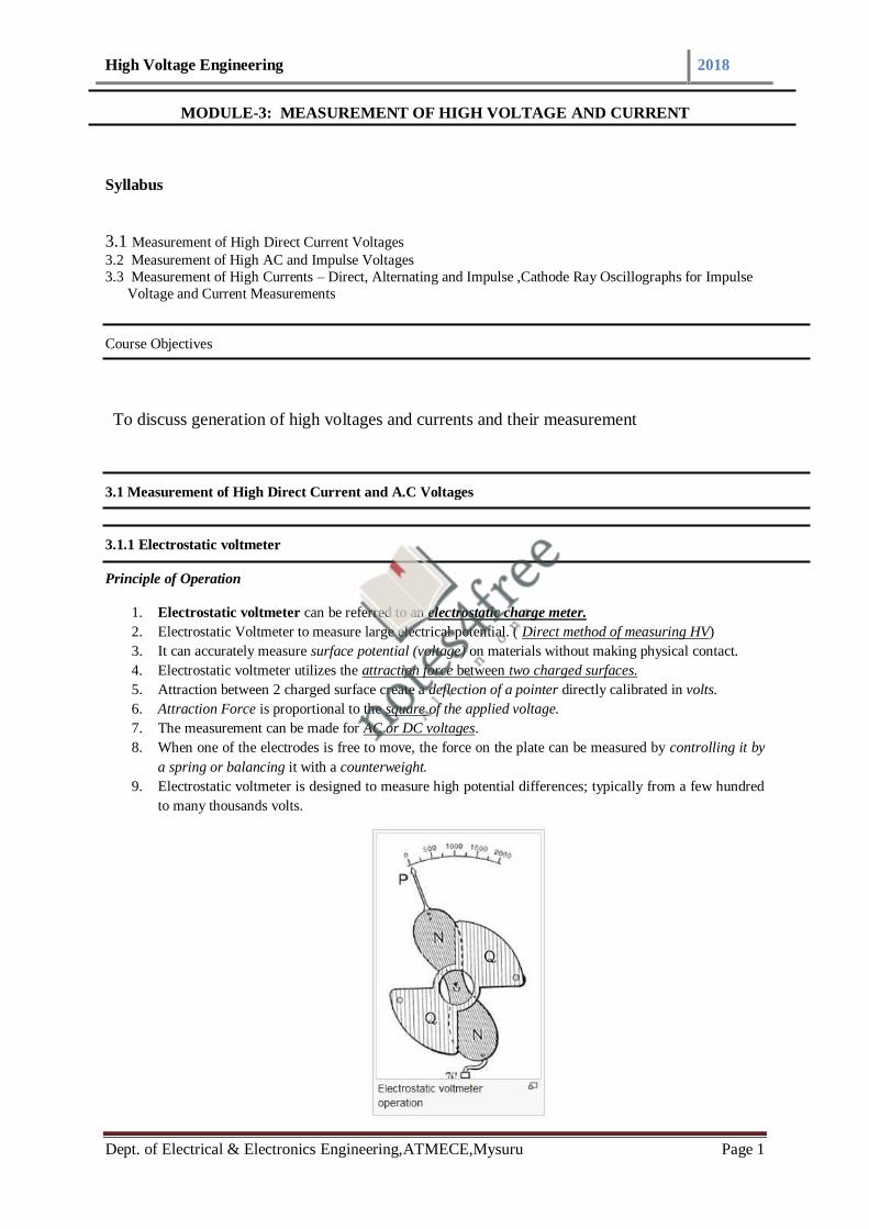
High Voltage Engineering 2018
Dept. of Electrical & Electronics Engineering,ATMECE,Mysuru Page 1
MODULE-3: MEASUREMENT OF HIGH VOLTAGE AND CURRENT
Syllabus
3.1 Measurement of High Direct Current Voltages
3.2 Measurement of High AC and Impulse Voltages
3.3 Measurement of High Currents – Direct, Alternating and Impulse ,Cathode Ray Oscillographs for Impulse
Voltage and Current Measurements
Course Objectives
To discuss generation of high voltages and currents and their measurement
3.1 Measurement of High Direct Current and A.C Voltages
3.1.1 Electrostatic voltmeter
Principle of Operation
1. Electrostatic voltmeter can be referred to an electrostatic charge meter.
2. Electrostatic Voltmeter to measure large electrical potential. ( Direct method of measuring HV)
3. It can accurately measure surface potential (voltage) on materials without making physical contact.
4. Electrostatic voltmeter utilizes the attraction force between two charged surfaces.
5. Attraction between 2 charged surface create a deflection of a pointer directly calibrated in volts.
6. Attraction Force is proportional to the square of the applied voltage.
7. The measurement can be made for AC or DC voltages.
8. When one of the electrodes is free to move, the force on the plate can be measured by controlling it by
a spring or balancing it with a counterweight.
9. Electrostatic voltmeter is designed to measure high potential differences; typically from a few hundred
to many thousands volts.

High Voltage Engineering 2018
Dept. of Electrical & Electronics Engineering,ATMECE,Mysuru Page 2
10. Electrostatic voltmeter utilizes the attraction force between two charged surfaces to create a deflection
of a pointer directly calibrated in volts.
11. The pivoted sector NN is attracted to the fixed sector QQ
12. The moving sector indicating the voltage by the pointer P and is counterbalanced by the small weight w.
13. Damping technique is Air friction damping.
In electrostatic fields, the attractive force between the electrodes of a parallel plate condenser is given by:
Fig: Schematic Diagram
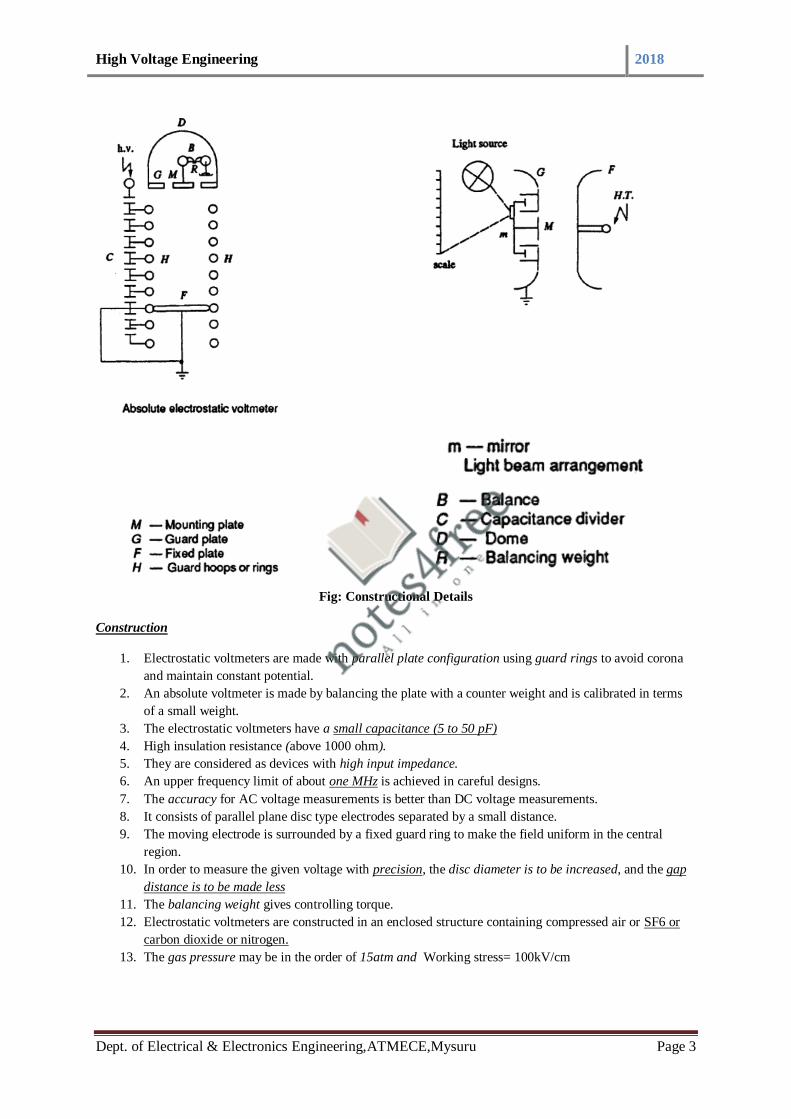
High Voltage Engineering 2018
Dept. of Electrical & Electronics Engineering,ATMECE,Mysuru Page 3
Fig: Constructional Details
Construction
1. Electrostatic voltmeters are made with parallel plate configuration using guard rings to avoid corona
and maintain constant potential.
2. An absolute voltmeter is made by balancing the plate with a counter weight and is calibrated in terms
of a small weight.
3. The electrostatic voltmeters have a small capacitance (5 to 50 pF)
4. High insulation resistance (above 1000 ohm).
5. They are considered as devices with high input impedance.
6. An upper frequency limit of about one MHz is achieved in careful designs.
7. The accuracy for AC voltage measurements is better than DC voltage measurements.
8. It consists of parallel plane disc type electrodes separated by a small distance.
9. The moving electrode is surrounded by a fixed guard ring to make the field uniform in the central
region.
10. In order to measure the given voltage with precision, the disc diameter is to be increased, and the gap
distance is to be made less
11. The balancing weight gives controlling torque.
12. Electrostatic voltmeters are constructed in an enclosed structure containing compressed air or SF6 or
carbon dioxide or nitrogen.
13. The gas pressure may be in the order of 15atm and Working stress= 100kV/cm

High Voltage Engineering 2018
Dept. of Electrical & Electronics Engineering,ATMECE,Mysuru Page 4
Advantages
1. Active power loss is negligibly small
2. Low loading effect
3. Voltage up to 600kV can be measured
Limitations
1. The measurement of voltage lower than 50V is not possible because force become too small.
2. For constant distance ‘s’, F α V2, the sensitivity is small. This can be overcome by varying the gap
distance d in appropriate steps.
3.2 Measurement of HVAC Voltages : Chubb and Fortescue method for HV AC measurement
1. It is a simple and accurate method for the peak measurement of AC voltage.
2. It can be defined as peak voltmeter method.
3. Suggested by Chubb and Fortescue in 1913.
4. Peak value of instrument is required for HV measurement.
5. Peak value of an AC waveform is more important.
6. When the waveform is not sinusoidal, rms value of the voltage multiplied by square root of 2 is not
correct.
7. Hence a separate peak value instrument is desirable in high voltage applications.

High Voltage Engineering 2018
Dept. of Electrical & Electronics Engineering,ATMECE,Mysuru Page 5
8. When a capacitor is connected to a sinusoidal voltage source, the charging current is generated.
9. The meter reading is proportional to the peak value of the value Vm.
where ‘I’ is the dc current read by the meter and C is the capacitance of the capacitor.
This method is known as the Chubb-Frotscue method for peak voltage measurement.
3.2.1 Generating voltmeter
1. “A generating voltmeter is a variable capacitor electrostatic voltage generator which generates
current proportional to the applied external voltage”
2. The device is driven by an external synchronous or constant speed motor and does not absorb power
or energy from the voltage measuring source. i.e no loading effect.
3. Generating volt meter can measure loss free AC voltage.
4. Generating voltmeters are high impedance devices.
5. No direct connection to the high voltage.
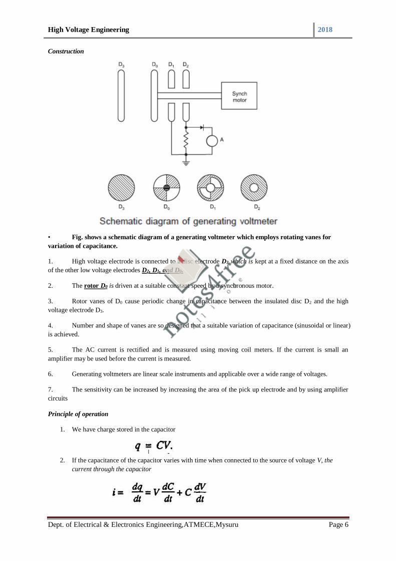
High Voltage Engineering 2018
Dept. of Electrical & Electronics Engineering,ATMECE,Mysuru Page 6
Construction
• Fig. shows a schematic diagram of a generating voltmeter which employs rotating vanes for
variation of capacitance.
1. High voltage electrode is connected to a disc electrode D3 which is kept at a fixed distance on the axis
of the other low voltage electrodes D2, D1, and D0.
2. The rotor D0 is driven at a suitable constant speed by a synchronous motor.
3. Rotor vanes of D0 cause periodic change in capacitance between the insulated disc D2 and the high
voltage electrode D3.
4. Number and shape of vanes are so designed that a suitable variation of capacitance (sinusoidal or linear)
is achieved.
5. The AC current is rectified and is measured using moving coil meters. If the current is small an
amplifier may be used before the current is measured.
6. Generating voltmeters are linear scale instruments and applicable over a wide range of voltages.
7. The sensitivity can be increased by increasing the area of the pick up electrode and by using amplifier
circuits
Principle of operation
1. We have charge stored in the capacitor
2. If the capacitance of the capacitor varies with time when connected to the source of voltage V, the
current through the capacitor

High Voltage Engineering 2018
Dept. of Electrical & Electronics Engineering,ATMECE,Mysuru Page 7
3. For a constant angular frequency, the current is proportional to the applied voltage V.
4. More often, the generated current is rectified and measured by a moving coil meter.
5. Generating voltmeter can be used for AC voltage measurements also provided the angular frequency
is the same or equal to half that of the supply frequency.
Advantages of Generating Voltmeters
1. No source loading by the meter
2. No direct connection to high voltage electrode
3. scale is linear and extension of range is easy
4. A very convenient instrument for electrostatic devices such as Van de Graff generator and particle
accelerators.
Limitations of Generating Voltmeters
1. They require calibration
2. Careful construction is needed and is a cumbersome instrument requiring an auxiliary drive
3. Disturbance in position and mounting of the electrodes make the calibration invalid.
Numerical
Solution:

High Voltage Engineering 2018
Dept. of Electrical & Electronics Engineering,ATMECE,Mysuru Page 8
3.2.2 Series resistance micro ammeter
1. A large value of resistance (few hundreds of mega ohms) is connected in series with uA.
2. Protective device (Zener diode) connected across the uA.
Need for protective device:
1. If R fails, heavy current will flow through µA
2. To divert protective device is used
Operation of series resistance micro ammeter
1. “R ”should be high
2. High DC voltage is applied
3. Voltage drop across the resistance
4. The current flowing through the resistance ‘R’ is measured in µA.

High Voltage Engineering 2018
Dept. of Electrical & Electronics Engineering,ATMECE,Mysuru Page 9
5. The resistance is constructed from a large no. of wire wound resistors in series.
6. Voltage V=IR
7. Drop in Ammeter is negligible
8. R should be chosen such that 1 to 10 uA is allowed for full scale deflection 500 kV can be measured
9. Accuracy : 20%
Drawbacks
1. More power dissipation
2. Temperature effects
3. Source loading.
Functions of series resistance
i) Limit the breakdown current
ii) To suppress unwanted oscillations
3.2.3 Standard Sphere Gap Measurement
a) Importance of sphere gap measurement
1. Peak value of voltage causes dielectric breakdown.
2. A sphere gap can be used for measurement of the peak value of the voltage if the gap distance is
known.
3. Sphere gap measurement is one of the standard method of measuring peak value of high voltage DC,
AC and impulse voltage.
4. It is used for checking voltmeters and other voltage measuring devices used in HV testing circuits.
5. Two types of sphere gap arrangement
a. Horizontal sphere gap arrangement
b. Vertical sphere gap arrangement
b) Construction
Standard diameter of the spheres are 2, 5, 6.25, 10, 12.5, 15, 25, 50, 75,100, 150 and 200cm.
a. Horizontal arrangement is usually is preferred for sphere diameter d<50cm and it is suitable for low
voltage range.
b. One of the sphere is static and other is movable (adjustable).
c. Impulse voltage which has wave front time at least 1μs & wave tail time of 5μs can be measured using
sphere gap measurement.
a. Horizontal arrangement of sphere gap
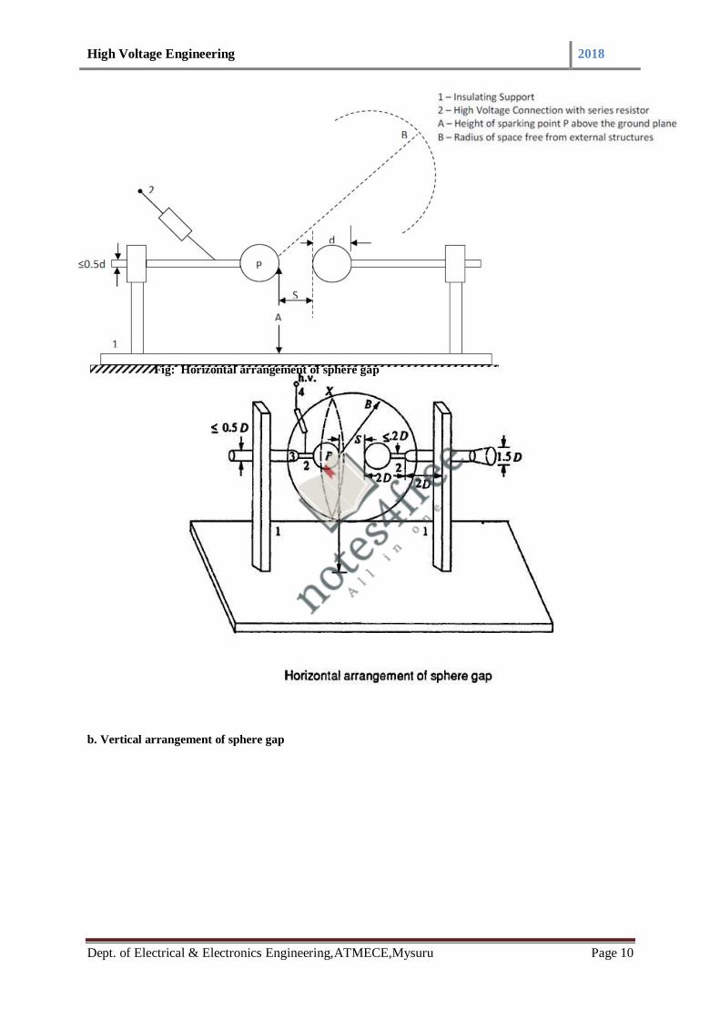
High Voltage Engineering 2018
Dept. of Electrical & Electronics Engineering,ATMECE,Mysuru Page 10
Fig: Horizontal arrangement of sphere gap
b. Vertical arrangement of sphere gap

High Voltage Engineering 2018
Dept. of Electrical & Electronics Engineering,ATMECE,Mysuru Page 11
Construction
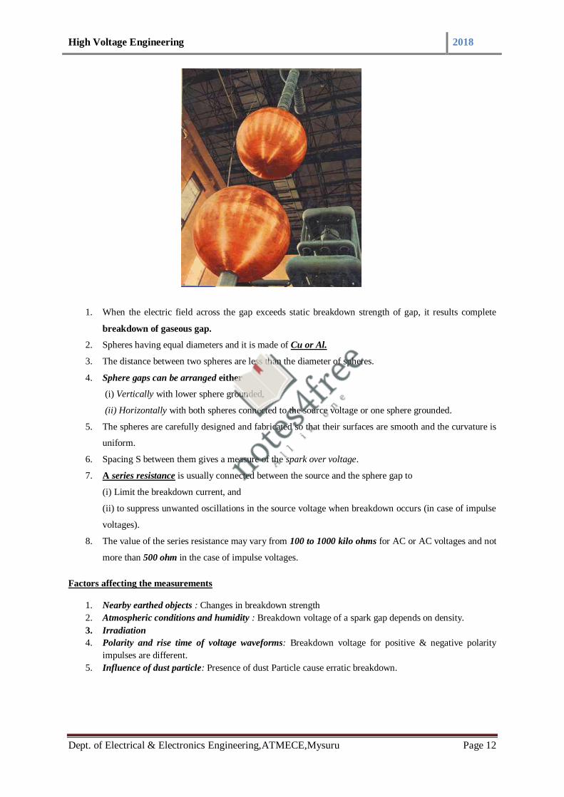
High Voltage Engineering 2018
Dept. of Electrical & Electronics Engineering,ATMECE,Mysuru Page 12
1. When the electric field across the gap exceeds static breakdown strength of gap, it results complete
breakdown of gaseous gap.
2. Spheres having equal diameters and it is made of Cu or Al.
3. The distance between two spheres are less than the diameter of spheres.
4. Sphere gaps can be arranged either
(i) Vertically with lower sphere grounded,
(ii) Horizontally with both spheres connected to the source voltage or one sphere grounded.
5. The spheres are carefully designed and fabricated so that their surfaces are smooth and the curvature is
uniform.
6. Spacing S between them gives a measure of the spark over voltage.
7. A series resistance is usually connected between the source and the sphere gap to
(i) Limit the breakdown current, and
(ii) to suppress unwanted oscillations in the source voltage when breakdown occurs (in case of impulse
voltages).
8. The value of the series resistance may vary from 100 to 1000 kilo ohms for AC or AC voltages and not
more than 500 ohm in the case of impulse voltages.
Factors affecting the measurements
1. Nearby earthed objects : Changes in breakdown strength
2. Atmospheric conditions and humidity : Breakdown voltage of a spark gap depends on density.
3. Irradiation
4. Polarity and rise time of voltage waveforms: Breakdown voltage for positive & negative polarity
impulses are different.
5. Influence of dust particle: Presence of dust Particle cause erratic breakdown.
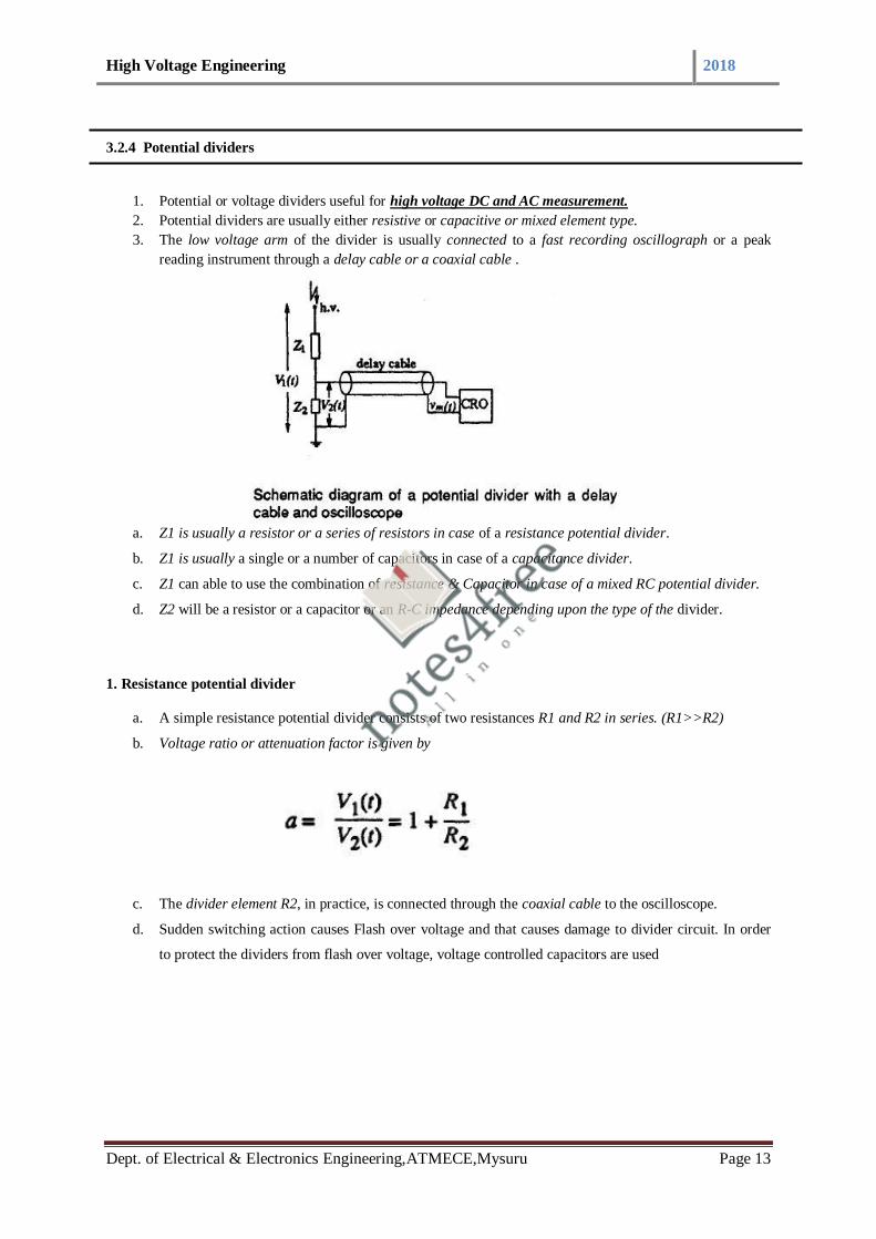
High Voltage Engineering 2018
Dept. of Electrical & Electronics Engineering,ATMECE,Mysuru Page 13
3.2.4 Potential dividers
1. Potential or voltage dividers useful for high voltage DC and AC measurement.
2. Potential dividers are usually either resistive or capacitive or mixed element type.
3. The low voltage arm of the divider is usually connected to a fast recording oscillograph or a peak
reading instrument through a delay cable or a coaxial cable .
a. Z1 is usually a resistor or a series of resistors in case of a resistance potential divider.
b. Z1 is usually a single or a number of capacitors in case of a capacitance divider.
c. Z1 can able to use the combination of resistance & Capacitor in case of a mixed RC potential divider.
d. Z2 will be a resistor or a capacitor or an R-C impedance depending upon the type of the divider.
1. Resistance potential divider
a. A simple resistance potential divider consists of two resistances R1 and R2 in series. (R1>>R2)
b. Voltage ratio or attenuation factor is given by
c. The divider element R2, in practice, is connected through the coaxial cable to the oscilloscope.
d. Sudden switching action causes Flash over voltage and that causes damage to divider circuit. In order
to protect the dividers from flash over voltage, voltage controlled capacitors are used

High Voltage Engineering 2018
Dept. of Electrical & Electronics Engineering,ATMECE,Mysuru Page 14
e. The cable will generally have a surge impedance Z0
f. Surge impedance will come in parallel with the oscilloscope input impedance (Rm , Cm).
g. Rm will generally be greater than one Mega ohm and Cm may be 10 to 50 picofarads.
h. For high frequency and impulse voltages, the ratio in the frequency domain will be given by

High Voltage Engineering 2018
Dept. of Electrical & Electronics Engineering,ATMECE,Mysuru Page 15
2. Capacitive potential divider
Impulse voltage can be measured by using capacitive potential dividers
C1 - Standard Compressed Gas H.V. Condenser
C2 - Standard Low Voltage Condenser
ESV- Electrostatic Voltmeter P -Protective Gap C.C - Connecting Cable
1. Harmonic Effects can be eliminated by use of Capacitive Potential Dividers (CPD) with Electro Static
Voltmeter (ESV).
2. Gas filled condensers C1 and C2 are used as shown in figure.
3. C1 is a three terminal capacitor, connected to C2 by shielded cable.
4. C2 is shielded to avoid stray capacitance
5. Capacitive potential divider can measure fast rising voltage & pulse and impulse voltage.
6. Capacitance ratio is independent of frequency.
7. Ratio of the divider (Attenuation factor) is given by
8. Capacitance C1 is formed between the HV terminal of the source.
9. Suitable for measuring the impulse voltage up to 1 MV
10. C1 is the standard compressed air or gas condenser- HV Capacitor.
11. Value of C2 is very high, C2 may be mica capacitor, paper capacitor etc
12. C1 is connected to C2 by using a shield cable
13. C2 is completely covered by using a box, for avoiding stray capacitance.
14. Voltage can measure by using VTVM (Vacuum Tube Volt Meter) or ESV- testing purpose for
impulse voltage

High Voltage Engineering 2018
Dept. of Electrical & Electronics Engineering,ATMECE,Mysuru Page 16
Impulse voltage measurement by using capacitive
V1- Voltage to be measured
V2-Meter reading
C1-Standard compressed gas HV condenser
C2-Standard low voltage condenser Cm-Capacitance of the meter
Advantages
1. Loading on the source is negligible
2. Capacitance ratio independent of frequency
3. Mixed RC potential divider
1. Mixed potential dividers use R-C elements in series or in parallel.
2. Improved step response
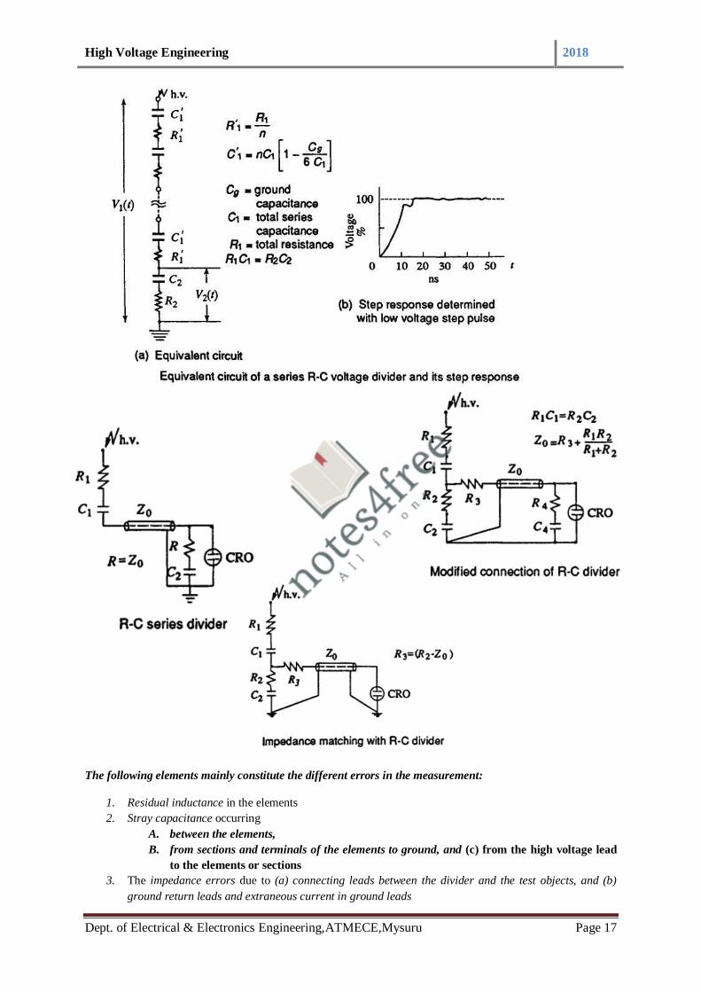
High Voltage Engineering 2018
Dept. of Electrical & Electronics Engineering,ATMECE,Mysuru Page 17
The following elements mainly constitute the different errors in the measurement:
1. Residual inductance in the elements
2. Stray capacitance occurring
A. between the elements,
B. from sections and terminals of the elements to ground, and (c) from the high voltage lead
to the elements or sections
3. The impedance errors due to (a) connecting leads between the divider and the test objects, and (b)
ground return leads and extraneous current in ground leads
High Voltage Engineering 2018
Dept. of Electrical & Electronics Engineering,ATMECE,Mysuru Page 18
4. Parasitic oscillations due to lead and cable inductances and capacitance of high voltage terminal to
ground.
Additional Information
Note1 -surge impedance
• The characteristic impedance or surge impedance of a uniform transmission line, usually written Z0, is
the ratio of the amplitudes of voltage and current of a single wave propagating along the line.
• That is, a wave travelling in one direction in the absence of reflections in the other direction.
• Characteristic impedance is determined by the geometry and materials of the transmission line and, for
a uniform line, is not dependent on its length. The SI unit of characteristic impedance is the ohm.
Note 2-Parasitic capacitance
• In electrical circuits, parasitic capacitance, stray capacitance or, when relevant, self-capacitance, is an
unavoidable and usually unwanted capacitance that exists between the parts of an electronic component or
circuit simply because of their proximity to each other.
• All actual circuit elements such as inductors, diodes, and transistors have internal capacitance, which
can cause their behavior to depart from that of 'ideal' circuit elements.
• Additionally, there is always non-zero capacitance between any two conductors; this can be significant
at higher frequencies with closely spaced conductors, such as wires or printed circuit board traces.
3.3 Measurement of Impulse current
1. In power system applications as well as in other scientific and technical fields, it is often
necessary to determine the amplitude and waveforms of rapidly varying high currents.
2. High impulse currents occur in lightning discharges, electrical arcs and post arc phenomenon
studies with circuit breakers, and with electric discharge studies in plasma physics.
Rogowski Coils
Measurement of high impulse current
1. A Rogowski coil, named by Walte Rogowski, is an electrical device for measuring Alternating
Current(AC) or high speed current pulses.
2. It consists of a helical coil of wire with the lead from one end returning through the centre of the coil to
the other end, so that both terminals are at the same end of the coil.
3. The whole assembly is then wrapped around the straight conductor whose current is to be measured.
4. Since the voltage that is induced in the coil is proportional to the rate of change of current in the
straight conductor.
5. There is no metal (iron) core.
“A Rogowski coil is a toroid of wire used to measure an alternating current i(t) through a cable encircled
by the toroid”
1. Connected to an electrical (or electronic) The output of the Rogowski coil is usually integrator
circuit to provide an output signal that is proportional to the current
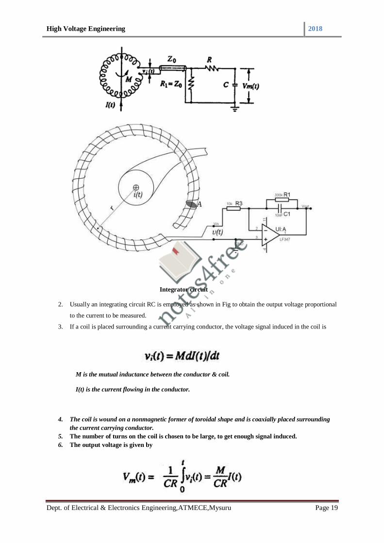
High Voltage Engineering 2018
Dept. of Electrical & Electronics Engineering,ATMECE,Mysuru Page 19
Integrator circuit
2. Usually an integrating circuit RC is employed as shown in Fig to obtain the output voltage proportional
to the current to be measured.
3. If a coil is placed surrounding a current carrying conductor, the voltage signal induced in the coil is
M is the mutual inductance between the conductor & coil.
I(t) is the current flowing in the conductor.
4. The coil is wound on a nonmagnetic former of toroidal shape and is coaxially placed surrounding
the current carrying conductor.
5. The number of turns on the coil is chosen to be large, to get enough signal induced.
6. The output voltage is given by

High Voltage Engineering 2018
Dept. of Electrical & Electronics Engineering,ATMECE,Mysuru Page 20
7. Rogowski coils with electronic or active integrator circuits have large bandwidths (about 100
MHz).
8. At frequencies greater than 100 MHz the response is affected by the skin effect.
Advantages
1. Lower construction costs.
2. Temperature compensation is simple.
3. No iron core to saturate
Disadvantages
1. Maintenance of integrators circuit
3.3.1 Magnetic Link
1. These can be used for measurement of peak value of impulse currents.
2. Magnetic links are high retentively steel strips arranged on a circular wheel or drum.
3. These strips have the property that the remanent magnetism (residual magnetism) for a current pulse of
0.5/5 µs is same as that caused by a d.c. current of the same value.
4. Remenent magnetism or Residual magnetism is the magnetization left behind in a feromagnetic
material after an external magnetic field is removed
5. The strips will be kept at a known distance from the current carrying conductor and parallel to it.
6. The Remanent magnetism (Residual magnetism) is then measured in the laboratory from which the
peak value of the current can be estimated.
7. These are useful for field measurements, mainly for estimating the lightning currents on the
transmission lines and towers.
8. By using a number of links, accurate measurement of the peak value, polarity, and the percentage
oscillations in lightning currents can be made.
3.3.2 Cathode Ray Oscillograph for Impulse Measurements:
Modern Cathode Ray Oscillograph for Impulse Measurements are sealed tube, hot cathode oscilloscopes with
photographic arrangement for recording the waveforms. The cathode ray oscilloscope for impulse work
normally has input voltage range from 5 m V/cm to about 20 V/cm. In addition, there are probes
and attenuators to handle signals up to 600 V (peak to peak). The bandwidth and rise time of
the oscilloscope should be adequate. Rise times of 5 ns and bandwidth as high as 500 MHz may be necessary.
Sometimes high voltage surges test oscilloscopes do not have vertical amplifier and directly require an input
voltage of 10 V. They can take a maximum signal of about 100 V (peak to peak) but require
suitable attenuators for large signals.
Oscilloscopes are fitted with good cameras for recording purposes. Tektronix model 7094 is fitted with a lens of
1 : 1.2 polaroid camera which uses 10.000 ASA film which possesses a writing speed of 9 cm/ns.

High Voltage Engineering 2018
Dept. of Electrical & Electronics Engineering,ATMECE,Mysuru Page 21
With rapidly changing signals, it is necessary to initiate or start the oscilloscope time base before the signal
reaches the oscilloscope deflecting plates, otherwise a portion of the signal may be missed. Such measurements
require an accurate initiation of the horizontal time base and is known as triggering. Oscilloscopes are normally
provided with both internal and external triggering facility. When external triggering is used, as with recording
of impulses, the signal is directly fed to actuate the time base and then applied to the vertical or Y deflecting
plates through a delay line. The delay is usually 0.1 to 0.5 μs.
The delay is obtained by:
1. A long interconnecting coaxial cable 20 to 50 in long. The required triggering is obtained from an antenna
whose induced voltage is applied to the external trigger terminal.
2.The measuring signal is transmitted to the CRO by a normal coaxial cable. The delay is obtained by an
externally connected coaxial long cable to give the necessary delay. This arrangement is shown in Fig. 7.55.
3.The impulse generator and the time base of the CRO are triggered from an electronic tripping device. A first
pulse from the device starts the CRO time base and after a predetermined time a second pulse triggers the
impulse generator.
Course Outcome
At the end of the course,students will be able to:
Discuss measurement techniques for high voltages and currents.

High Voltage Engineering 2018
Dept. of Electrical & Electronics Engineering,ATMECE,Mysuru Page 1
MODULE-4: Overvoltage Phenomenon and Insulation Coordination in Electric Power Systems
Syllabus
4.1 National Causes for Over voltages - Lightning Phenomenon, Overvoltage due to Switching Surges,
4.2 System Faults and Other Abnormal
4.3 Principles of Insulation Coordination on High Voltage and Extra High Voltage Power Systems
Course Objectives
To discuss overvoltage phenomenon and insulation coordination in electric power systems.
4.1 National Causes for Over voltages - Lightning Phenomenon, Overvoltage due to Switching Surges
a) Causes of Over voltage in Power System
Increase in voltage for the very short time in power system is called as the over voltage. it is also
known as the voltage surge or voltage transients. The voltage stress caused by over voltage can
damage the lines and equipment’s connected to the system, There are two types of causes of over
voltage in power system.
1. Over voltage due to external causes
2. Over voltage due to internal causes
Transient over voltages can be generated at high frequency (load switching and lightning),
medium frequency (capacitor energizing), or low frequency.Over voltage due to external causes:
This cause of over voltage in power system is the lightning strokes in the cloud.
Now, how lightning strokes are produced. So when electric charges get accumulated in clouds
due to thunder Strom caused due to some bad atmosphere process.
This type of over voltages originates from atmospheric disturbances, mainly due to lightning.
This takes the form of a surge and has no direct relationship with the operating voltage of the line.
It may be due to any of the following causes:
A) Direct lightning stroke
B) Electromagnetically induced over voltages due to lightning discharge taking place near the
line, called ‘side stroke’.
C) Voltages induced due to atmospheric changes along the length of the line.
D) Electrostatically induced voltages due to presence of charged clouds nearby.

High Voltage Engineering 2018
Dept. of Electrical & Electronics Engineering,ATMECE,Mysuru Page 2
E) Electrostatically induced over voltages due to the frictional effects of small particles like dust
or dry snow in the atmosphere or due to change in the altitude of the line.
The potential between the clouds and earth breaks down and lightning flash takes place between
the cloud and ground when this voltage becomes 5 to 20 million volts or when the potential
gradient becomes 5000V to 10000V per cm.
There are two types of lightning strokes.
b) LIGHTNING ,SWITCHING AND TEMPORARY OVER VOLTAGE
over-voltage-spike
Over voltages are caused on power systems due to external and internal influencing factors. The voltage stress
caused by over voltage can damage the lines and equipment’s connected to the system. Over voltages arising on
a system can be generally classified into two main categories as below:
External Over voltages
This type of over voltages originates from atmospheric disturbances, mainly due to lightning. This takes the
form of a surge and has no direct relationship with the operating voltage of the line. It may be due to any of the
following causes:
a) Direct lightning stroke
b) Electromagnetically induced over voltages due to lightning discharge taking place near the line, called 'side
stroke'.
c) Voltages induced due to atmospheric changes along the length of the line.
d) Electrostatically induced voltages due to presence of charged clouds nearby.
e) Electrostatically induced over voltages due to the frictional effects of small particles like dust or
dry snow in the atmosphere or due to change in the altitude of the line.
High Voltage Engineering 2018
Dept. of Electrical & Electronics Engineering,ATMECE,Mysuru Page 3
Internal Over voltages
These over voltages are caused by changes in the operating conditions of the power system. These can
be divided into two groups as below:
1. Switching over voltages or Transient over operation voltages of high frequency:
This is caused when switching operation is carried out under normal conditions or when fault occurs in the
network. When an unloaded long line is charged, due to Ferranti Effect the receiving end voltage is increased
considerably resulting in over voltage in the system. Similarly when the primary side of the transformers or
reactors is switched on, over voltage of transient nature occurs.
2. Temporary over voltages:
These are caused when some major load gets disconnected from the long line under normal or steady state
condition.
4.2 System Faults
Over voltage tends to stress the insulation of the electrical equipment’s and likely to cause damage to them
when it frequently occurs. Over voltage caused by surges can result in spark over and flash over between phase
and ground at the weakest point in the network, breakdown of gaseous/solid/ liquid insulation, failure of
transformers and rotating machines.
4.2.1 Overvoltage Protection
There are always a chance of suffering an electrical power system from abnormal over voltages. These abnormal
over voltages may be caused due to various reason such as, sudden interruption of heavy load, lightening
impulses, switching impulses etc. These over voltage stresses may damage insulation of various equipments and
insulators of the power system. Although, all the over voltage stresses are not strong enough to damage
insulation of system, but still these over voltages also to be avoided to ensure the smooth operation of electrical
power system.
These all types of destructive and non destructive abnormal over voltages are eliminated from the system by
means of overvoltage protection.
4.2.3 Voltage Surge
The over voltage stresses applied upon the power system, are generally transient in nature. Transient voltage or
voltage surge is defined as sudden sizing of voltage to a high peak in very short duration.The voltage surges are
transient in nature, that means they exist for very short duration. The main cause of these voltage surges in
power system are due to lightning impulses and switching impulses of the system. But over voltage in the power
system may also be caused by, insulation failure, arcing ground and resonance etc.
The voltage surges appear in the electrical power system due to switching surge, insulation failure, arcing
ground and resonance are not very large in magnitude. These over voltages hardly cross the twice of the normal
voltage level. Generally, proper insulation to the different equipment of power system is sufficient to prevent

High Voltage Engineering 2018
Dept. of Electrical & Electronics Engineering,ATMECE,Mysuru Page 4
any damage due to these over voltages. But over voltages occur in the power system due to lightning is very
high. If over voltage protection is not provided to the power system, there may be high chance of severe damage.
Hence all over voltage protection devices used in power system mainly due to lightning surges.
4.2.3 Switching Impulse
Switching Impulse or Switching Surge
When a no load transmission line is suddenly switched on, the voltage on the line becomes twice of normal
system voltage. This voltage is transient in nature. When a loaded line is suddenly switched off or interrupted,
voltage across the line also becomes high enough current chopping in the system mainly during opening
operation of air blast circuit breaker, causes over voltage in the system. During insulation failure, a live
conductor is suddenly earthed. This may also caused sudden over voltage in the system. If emf wave produced
by alternator is distorted, the trouble of resonance may occur due to 5th or higher harmonics. Actually for
frequencies of 5th or higher harmonics, a critical situation in the system so appears, that inductive reactance of
the system becomes just equal to capacitive reactance of the system. As these both reactance cancel each other
the system becomes purely resistive. This phenomenon is called resonance and at resonance the system voltage
may be increased enough.
But all these above mentioned reasons create over voltages in the system which are not very high in magnitude.
But over voltage surges appear in the system due to lightning impulses are very high in amplitude and highly
destructive. The affect of lightning impulse hence must be avoided for over voltage protection of power system.
Methods of Protection Against Lightning
These are mainly three main methods generally used for protection against lightning. They are
Earthing screen.
Overhead earth wire.
Lighning arrester or surge dividers.
Earthing Screen
Earthing screen is generally used over electrical substation. In this arrangement a net of GI wire is mounted over
the sub-station. The GI wires, used for earthing screen are properly grounded through different sub-station
structures. This network of grounded GI wire over electrical sub-station, provides very low resistance path to the
ground for lightning strokes.
This method of high voltage protection is very simple and economic but the main drawback is, it can not protect
the system from travelling wave which may reach to the sub-station via different feeders.
Overhead Earth Wire

High Voltage Engineering 2018
Dept. of Electrical & Electronics Engineering,ATMECE,Mysuru Page 5
This method of over voltage protection is similar as earthing screen. The only difference is, an earthing screen is
placed over an electrical sub-station, whereas, overhead earth wire is placed over electrical transmission
network. One or two stranded GI wires of suitable cross-section are placed over the transmission conductors.
These GI wires are properly grounded at each transmission tower. These overhead ground wires or earth wire
divert all the lightning strokes to the ground instead of allowing them to strike directly on the transmission
conductors.
Lightning Arrester
The previously discussed two methods, i.e. earthing screen and over-head earth wire are very suitable for
protecting an electrical power system from directed lightning strokes but system from directed lightning strokes
but these methods can not provide any protection against high voltage travelling wave which may propagate
through the line to the equipment of the sub-station.The lightning arrester is a devices which provides very low
impedance path to the ground for high voltage travelling waves.
The concept of a lightning arrester is very simple. This device behaves like a nonlinear electrical resistance. The
resistance decreases as voltage increases and vice-versa, after a certain level of voltage.The functions of a
lightning arrester or surge dividers can be listed as below.
Under normal voltage level, these devices withstand easily the system voltage as electrical insulator and provide
no conducting path to the system current.
On occurrence of voltage surge in the system, these devices provide very low impedance path for the excess
charge of the surge to the ground.
After conducting the charges of surge, to the ground, the voltage becomes to its normal level. Then lightning
arrester regains its insulation properly and prevents regains its insulation property and prevents further
conduction of current, to the ground.
There are different types of lightning arresters used in power system, such as rod gap arrester, horn gap arrester,
multi-gap arrester, expulsion type LA, value type LA. In addition to these the most commonly used lightning
arrester for over voltage protection now-a-days gapless ZnO lightning arrester is also used.
4.3 Insulation Co-ordination
Insulation Coordination in Power System was introduced to arrange the electrical insulation levels of different
components in the electrical power system including transmission network, in such a manner, that the failure of
insulator, if occurs, confindes to the place where it would result in the least danmage of the system, easy to
repair and replace, and results least disturbance to the power supply.
When any over voltage appears in the electrical power system, then there may be a chance of failure of its
insulation system. Probability of failure of insulation, is high at the weakest insulation point nearest to the
source of over voltage. In power system and transmission networks, insulation is provided to the all equipment
and components.

High Voltage Engineering 2018
Dept. of Electrical & Electronics Engineering,ATMECE,Mysuru Page 6
Insulators in some points are easily replaceable and repairable compared to other. Insulation in some points are
not so easily replaceable and repairable and the replacement and repairing may be highly expensive and require
long interruption of power. Moreover failure of insulator at these points may causes bigger part of electrical
network to be out of service. So, it is desirable that in situation of insulator failure, only the easily replaceable
and repairable insulator fails. The overall aim of insulation coordination is to reduce to an economically and
operationally acceptable level the cost and disturbance caused by insulation failure. In insulation coordination
method, the insulation of the various parts of the system must be so graded that flash over if occurs it must be at
intended points.
For proper understanding the insulation coordination we have to understand first, some basic terminologies of
the electrical power system. Let us have a discussion.
Nominal System Voltage
Nominal System Voltage is the phase to phase voltage of the system for which the system is normally designed.
Such as 11 KV, 33 KV, 132 KV, 220 KV, 400 KV systems.
Maximum System Voltage
Maximum System Voltage is the maximum allowable power frequency voltage which can occurs may be for
long time during no load or low load condition of the power system. It is also measured in phase to phase
manner.
List of different nominal system voltage and their corresponding maximum system voltage is given below for
reference,
Nominal System Voltage in KV 11 33 66 132 220 400
Maximum System Voltage in KV 12 36 72.5 145 245 420
NB - It is observed from above table that generally maximum system voltage is 110 % of corresponding
nominal system voltage up to voltage level of 220 KV, and for 400 KV and above it is 105 %.
Factor of Earthing
This is the ratio of the highest rms phase to earth power frequency voltage on a sound phase during an earth
fault to the rms phase to phase power frequency voltage which would be obtained at the selected location
without the fault.
This ratio characterizes, in general terms, the earthing conditions of a system as viewed from the selected fault
location.
Effectively Earthed System

High Voltage Engineering 2018
Dept. of Electrical & Electronics Engineering,ATMECE,Mysuru Page 7
A system is said to be effectively earthed if the factor of earthing does not exceed 80 % and non-effectively
earthed if it does.Factor of earthing is 100 % for an isolated neutral system, while it is 57.7 % (1/√3 = 0.577) for
solidly earthed system.
Insulation Level
Every electrical equipment has to undergo different abnormal transient over voltage situation in different times
during its total service life period. The equipment may have to withstand lightning impulses, switching impulses
and/or short duration power frequency over voltages. Depending upon the maximum level of impulse voltages
and short duration power frequency over voltages that one power system component can withstand, the
insulation level of high voltage power system is determined.
During determining the insulation level of the system rated less than 300 KV, the lightning impulse withstand
voltage and short duration power frequency withstand voltage are considered. For equipment rated more or
equal 300 KV, switching impulse withstand voltage and short duration power frequency withstand voltage are
considered.
Lightning Impulse Voltage
The system disturbances occur due to natural lightning, can be represented by three different basic wave shapes.
If a lightning impulse voltage travels some distance along the transmission line before it reaches to a insulator
its wave shaped approaches to full wave, and this wave is referred as 1.2/50 wave. If during travelling, the
lightning disturbance wave causes flash over across an insulator the shape of the wave becomes chopped wave.
If a lightning stroke hits directly on the insulator then the lightning impulse voltage may rise steep until it is
relieved by flash over, causing sudden, very steep collapse in voltage. These three waves are quite different in
duration and in shapes.
Switching Impulse
During switching operation there may be uni-polar voltage appears in the system. The wave form of which may
be periodically damped or oscillating one. Switching impulse wave form has steep front and long damped
oscillating tale.
Short Duration Power Frequency Withstand Voltage
Short duration power frequency withstand voltage is the prescribed rms value of sinusoidal power frequency
voltage that the electrical equipment shall withstand for a specific period of time normally 60 seconds.
Protection Level Voltage of Protective Device
Over voltage protective device like surge arrestors or lightning arrestors are designed to withstand a certain level
of transient over voltage beyond which the devices drain the surge energy to the ground and therefore maintain
the level of transient over voltage up to a specific level. Thus transient over voltage can not exceed that level.
The protection level of over voltage protective device is the highest peak voltage value which should not be

High Voltage Engineering 2018
Dept. of Electrical & Electronics Engineering,ATMECE,Mysuru Page 8
exceeded at the terminals of over voltage protective device when switching impulses and lightening impulses
are applied.
As we discussed above that a component of electrical power system may suffer from different level of transient
voltage stresses, switching impulse voltage and lightning impulse voltage. The maximum amplitude of transient
over voltages reach the components, can be limited by using protecting device like lightning arrestors in the
system. If we maintain the insulation level of all the power system component above the protection level of
protective device, then ideally there will be no chance of breakdown of insulation of any component. Since the
transient over voltage reaches at the insulation after crossing the surge protective devices will have amplitude
equals to protection level voltage and protection level voltage impulse insulation level of the components.
Generally, the impulse insulation level is established at 15 to 25 % above the protective level voltage of
protective devices.
Course Outcome
At the end of the course, student will be able to:
Discuss overvoltage phenomenon and insulation coordination in electric power systems.

High Voltage Engineering 2018
Department of EEE,ATMECE,Mysuru Page 1
MODULE 5: Non-Destructive Testing of Materials and Electrical Apparatus:
Syllabus
5.1 Introduction, Measurement of Dielectric Constant and Loss Factor, Partial Discharge Measurements.
5.2 High Voltage Testing of Electrical Apparatus: Testing of Insulators and Bushings, Testing of Isolators and
Circuit Breakers
5.3 Testing of Cables, Testing of Transformers, Testing of Surge Arrestors, Radio Interference Measurements,
Testing of HVDC Valves and Equipment.
5.1 Introduction
What is Non-destructive Testing?
It is a wide group of analysis techniques used in science, industry & Engineering to evaluate
the properties of Insulating material, component or system without causing damage.
It is very difficult to test the quality of insulating material after it forms part of equipment,
suitable tests must be done to ensure in the said range of operation.
Non-Destructive Testing (NDT) is ensure that the material is not destroyed as in the case of
high voltage testing.
NDT helps to estimate the electrical properties such as resistivity, dielectric constant & loss
factor , loss angle & dielectric loss over a wide frequency range.
NDT is commonly used in , mechanical engineering, petroleum engineering, electrical
engineering, civil engineering, systems engineering, aeronautical engineering, medicine, and
art.
5.1.1 Dielectric loss
1. Dielectric loss measure the quantity of a dielectric material’s inherent dissipation of
electromagnetic energy converted into heat.
2. The dielectric loss can be expressed in terms of loss angle δ.
3. An efficient dielectric material supports a varying charge with minimal dissipation of energy
in the form of heat.
Dielectric loss angle
1. tan δ is called as loss angle or dissipation factor testing or loss tangent.
2. Helps to determine the quality of the cable insulation.
3. The cable and its insulation is compared to a parallel plate capacitor.
4. In a perfect capacitor, the voltage and current are phase shifted 90 degrees.
5. If there are impurities in the insulation, like water trees, electrical trees, moisture and air
pockets, etc. the resistance of the insulation decreases.
6. Resulting in an increase in resistive current through the insulation.
7. It is no longer a perfect capacitor

High Voltage Engineering 2018
Department of EEE,ATMECE,Mysuru Page 2
8. The current and voltage will no longer be shifted 90 degrees. It will be something less than
90 degrees.
9. The extent to which the phase shift is less than 90 degrees is indicative of the level of
insulation contamination/DIELECTRIC LOSS
10. This “Loss Angle” is measured and analyzed.
Fig represents an equivalent circuit of a cable, The tangent of the angle δ is measured
1. Perfect cable insulation δ=0
2. tan δ helps to find out the life expectancy of dielectrics
How to measure dielectric loss and loss angle of a dielectric material?
By using the following devices
1.HIGH VOLTAGE SCHERING BRIDGE
2.TRANSFORMER RATIO ARM BRIDGE
A) What is Schering bridge?
1. The Schering Bridge is an electrical circuit used for measuring the insulating properties of
electrical cables and equipment.
2. Accurate value of capacitance can be measured by using Schering bridge.
3. It is used to measure insulation properties such as dielectric loss and loss angle.
4. It has the advantage that the balance equation is independent of frequency.
5. We can able to find the Unknown capacitance by using Schering bridge ,
ie C1= C2R4/R3 R1=R3C4/C2
Loss angle tan δ= wR1C1

High Voltage Engineering 2018
Department of EEE,ATMECE,Mysuru Page 3
5.1.2 Transformer Ratio Arm Bridge
Why Transformer Ratio Arm Bridge?
1. If you are proceeding with conventional bridge balancing methods, the following
disadvantages will occur
2. For high frequency measurements, the arm with high resistance leads to difficulties due to
their residual inductance, capacitance and skin effect.
3. If the length of arm is large, shielding difficulties.
B) What is Transformer Ratio Arm Bridge?
1. This bridge provide more accurate results for the small capacitance measurements.
2. Using at least two arms.
3. Two types of Transformer Ratio Arm bridges are available
a)Voltage Ratio Arm bridge
b)Current Ratio Arm bridge
a)Voltage Ratio Arm bridge -Suitable for high frequency low voltage application
b)Current Ratio Arm Bridge -Used for high voltage low frequency application

High Voltage Engineering 2018
Department of EEE,ATMECE,Mysuru Page 4
Circuits for Transformer Ratio Arm Bridge
A) Transformer Voltage Ratio arm bridge
1. In practical situation due to the presence of magnetizing current and the load currents, the
voltage ratio slightly differ from the turns ratio.
2. Those errors are ratio errors & load error.
B) Transformer Current Ratio arm bridge
1. Suitable for high voltage low frequency applications.
2. The main component of the bridge is a three winding current transformer with very low
losses & leakage (core of high permeability).
3. Transformer is carefully shielded & protected against mechanical vibrations.

High Voltage Engineering 2018
Department of EEE,ATMECE,Mysuru Page 5
Transformer Current Ratio arm bridge- Calculations
5.1.3 Partial Discharge (PD)
1. Partial discharge (PD) is a localized dielectric breakdown of a small portion of a solid or fluid
electrical insulation system under high voltage stress.
2. The distance between two electrode is only partially bridged.
3. PD is responsible for reducing the insulation strength.
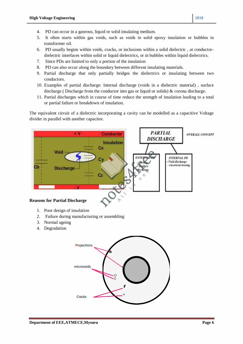
High Voltage Engineering 2018
Department of EEE,ATMECE,Mysuru Page 6
4. PD can occur in a gaseous, liquid or solid insulating medium.
5. It often starts within gas voids, such as voids in solid epoxy insulation or bubbles in
transformer oil.
6. PD usually begins within voids, cracks, or inclusions within a solid dielectric , at conductor-
dielectric interfaces within solid or liquid dielectrics, or in bubbles within liquid dielectrics.
7. Since PDs are limited to only a portion of the insulation
8. PD can also occur along the boundary between different insulating materials.
9. Partial discharge that only partially bridges the dielectrics or insulating between two
conductors.
10. Examples of partial discharge: Internal discharge (voids in a dielectric material) , surface
discharge ( Discharge from the conductor into gas or liquid or solids) & corona discharge.
11. Partial discharges which in course of time reduce the strength of insulation leading to a total
or partial failure or breakdown of insulation.
The equivalent circuit of a dielectric incorporating a cavity can be modelled as a capacitive Voltage
divider in parallel with another capacitor.
Reasons for Partial Discharge
1. Poor design of insulation
2. Failure during manufacturing or assembling
3. Normal ageing
4. Degradation

High Voltage Engineering 2018
Department of EEE,ATMECE,Mysuru Page 7
Types of partial Discharge
1.Corona or gas discharge- due to non uniform field, sharp edge of electrodes etc.
2.Surface discharge- interfacing of different dielectric material results over stress
3.Cavity discharge- over stress due to cavities
4.Treeing channels
Classification of Partial Discharge
5.1.3.1 Need for discharge detectors in dielectric measurement
1. Detectors are available in the wide range of frequency
2. Selection of detectors depends on bridge circuit & applications.
3. Dc measurements- dc galvanometer & dc amplifier with micro ammeter.
4. Power frequency measurements-vibration galvanometer.
5. Audio frequency range-tuned null detectors.
6. CRO or DSO can be used as a detector , if the requirement of sensitivity is very low.
a) Discharge Detection Methods
• Various methods are available for measuring discharge detection especially for analyzing Partial
Discharge (PD).
1.Discharge Detection using ‘straight detectors’
2.Balanced detection methods
3.Narrow band & Wide band circuits

High Voltage Engineering 2018
Department of EEE,ATMECE,Mysuru Page 8
1.Discharge Detection using ‘straight detectors’
Component descriptions of ‘straight detectors’
1. HV Transformer is free from discharge
2. The resonant filter is used to prevent any pulses starting from the capacitance of the windings
and bushings of the transformer
3. Cx is the test object- 100 pF to 0.1pF
4. Cc is the coupling capacitor
5. Zm is the detection impedance
6. The signal is developed across detection impedance Zm
7. Then the signal is passed through band pass filter (10kHz frequency) ,amplifier and displayed
Unit (on the CRO & multi channel analyzer unit)
Discharge patterns

High Voltage Engineering 2018
Department of EEE,ATMECE,Mysuru Page 9
Discharge patterns – voids in insulating materials
Drawbacks of straight detectors
1. Noise problems.
2. The filter used to block the noise sources may not be effective.
3. External disturbances are not fully rejected.
4. Tuning of filters is a difficult task.
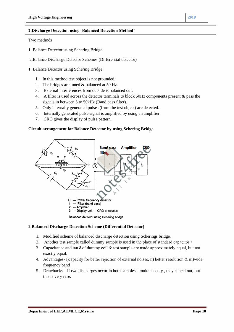
High Voltage Engineering 2018
Department of EEE,ATMECE,Mysuru Page 10
2.Discharge Detection using ‘Balanced Detection Method’
Two methods
1. Balance Detector using Schering Bridge
2.Balance Discharge Detector Schemes (Differential detector)
1. Balance Detector using Schering Bridge
1. In this method test object is not grounded.
2. The bridges are tuned & balanced at 50 Hz.
3. External interferences from outside is balanced out.
4. A filter is used across the detector terminals to block 50Hz components present & pass the
signals in between 5 to 50kHz (Band pass filter).
5. Only internally generated pulses (from the test object) are detected.
6. Internally generated pulse signal is amplified by using an amplifier.
7. CRO gives the display of pulse pattern.
Circuit arrangement for Balance Detector by using Schering Bridge
2.Balanced Discharge Detection Scheme (Differential Detector)
1. Modified scheme of balanced discharge detection using Scherings bridge.
2. Another test sample called dummy sample is used in the place of standard capacitor •
3. Capacitance and tan δ of dummy coil & test sample are made approximately equal, but not
exactly equal.
4. Advantages- i)capacity for better rejection of external noises, ii) better resolution & iii)wide
frequency band
5. Drawbacks – If two discharges occur in both samples simultaneously , they cancel out, but
this is very rare.

High Voltage Engineering 2018
Department of EEE,ATMECE,Mysuru Page 11
Circuit for Balanced Discharge Detection Scheme (Differential Detector)
Factors affecting discharge detection
1. Applied voltage
2. Different sample of material
3. Different void size
5.2 Definitions of terminologies,
1.Disruptive Discharge Voltage
• The voltage which produces the loss of dielectric strength of an insulation.
• Collapse of voltage & passage current
• Permanent loss for solid dielectrics, temporary loss for liquid and gaseous dielectrics.
2.Flashover
-when a discharge taking place in between two electrodes in a gas or liquid is called flashover.
3.Puncture
-when the discharge occur through solid insulation medium is called puncture
4.Withstand voltage- The voltage which has to be applied to a test object under specified condition
in a withstand test is called withstand voltage. ( as per IS:731 & IS:2099-1963)
5.Fifty per cent flashover voltage – This is the voltage which has a probability of 50% flashover
when applied to a test object which results loss of insulation strength temporarily.
6.Hundred per cent flash over voltage-The voltage ,that causes a flash over at each of its
applications under specified conditions , when applied to test objects as specified, is 100% flash over
voltage

High Voltage Engineering 2018
Department of EEE,ATMECE,Mysuru Page 12
7.Creepage Distance- It is the shortest distance between two metal fittings on the insulator or
dielectrics.
8.AC Test Voltage- Alternating test voltage should have power frequency in the range of 40 to 60 Hz
and approximately sinusoidal. The deviation allowed for the sinusoidal wave is 7%. The deviation
checked by measuring peak value, average vale & RMS value continuously. Computing average value,
RMS value & Form factor continuously.
9. Impulse Voltage- Impulse voltages are characterized by polarity, peak value, time to front, and
time to half the peak value after the peak
. • The time to front is defined as 1.5 times to time between 30% and 90% of the peak value in the
rising portion of the wave.
10.Reference Atmospheric Condition
• The electrical characteristics of the insulators and other apparatus are normally referred to the
reference atmospheric conditions
. • According to the Indian Standard Specifications
Based on British Standard Specifications
11. Air density correction factor

High Voltage Engineering 2018
Department of EEE,ATMECE,Mysuru Page 13
5.2.1 Test on Insulators
High voltage test includes
i)The power frequency tests &
ii) Impulse tests: All insulators are tested for both categories of test.
i)Power frequency test: Dry and wet flash over test, Wet & dry withstand tests (1 minute)
ii)Impulse Tests: Impulse withstand voltage test, Impulse flash over test and pollution testing
Why testing on insulators are required….?
1. To check the design features
2. To check the quality of test piece
i) Power frequency tests
(a) Dry and wet flashover test:
• The AC voltage of power frequency is applied across the insulators & increased at an uniform rate
of about 2% of the estimated test voltage, checking the breakdown.
• If the test is conducted without any rain or precipitation it is called as dry flashover test.
• If the test is done under condition of rain called as wet flash over test.
(b)Wet & dry withstand test
• In theses tests, the voltage specified in the relevant specification is applied under dry or wet
conditions for a period of one minute with an insulator mounted as in service conditions
. • The test piece should withstand the specified voltage.
ii)Impulse tests
(a)Impulse withstand voltage test
• This test is done by applying standard impulse voltage of specified value under dry condition with
positive & negative polarities.
High Voltage Engineering 2018
Department of EEE,ATMECE,Mysuru Page 14
• 5 consecutive waves are passed.
• That shouldn’t case flashover or puncture
(b) Impulse Flash over test
• Test is done under the specified voltage.
• Adjust the test voltage for the exact 50% flash over value.
• The insulation surface should not damaged.
(c) Pollution Testing
• Creating artificial pollution environment (salt fog test).
• Test duration – 1 hour.
Testing of Isolator & Circuit Breaker
Importance of isolator
1. Disconnector switch used for isolating the section of the circuit from any energized
conductor .
2. In HV , isolators are used in conjunction with circuit breaker
3. Isolators opened after a circuit breaker has opened the circuit, and closed before the circuit
breaker closes the circuit.
4. Off-load or minimum current breaking mechanical switch.
5. Isolator is operated after the circuit breaker to completely isolate the circuit.
6. Isolator is used to isolate the circuit permanently after a fault. Circuit breaker is used to
disconnect the circuit temporarily. That is the main difference between an isolator and CB.
Importance of circuit breaker
1. A circuit breaker is an automatically operated electrical switch designed to protect an
electrical circuit from damage caused by overload or short circuit.
2. Its basic function is to detect a fault condition and interrupt current flow.
3. On load or high current breaking switch
Why do we perform the testing of Isolators & Circuit breaker?
1. To evaluate operating characteristics
2. To study the constructional features
3. To calculate electrical parameters/characteristics
4. Conventional tests are available
1.The dielectric tests or over voltage tests
2. Impulse test
3.The temperature rise tests (Thermal test)

High Voltage Engineering 2018
Department of EEE,ATMECE,Mysuru Page 15
4.The mechanical tests
5. The short circuit tests
1. Dielectric tests or overvoltage tests
Objectives of Dielectric test:
1. This test consists of overvoltage withstand test of power frequency.
2. Testing of withstanding lightning & switching impulse voltage.
3. This test is done for checking internal & external insulation level. ie circuit breaker in open
and closed position.
4. Apply the test voltage separately when circuit breaker is in open and closed position.
Checking the internal insulation level
1. In the open position test voltage levels are 15% higher than the test voltage used when the
circuit breaker is closed. (Voltage in Open position >15% of that of closed position.)
2. Chance of line to ground flash over.
3. To avoid the flash over the circuit breaker is mounted on insulator above the ground.
4. So the insulation level of body of circuit breaker is raised.
5. We can measure the requirement of insulation level based on flashover
Wet dielectric test- To check the external insulation level
1. It is used for outdoor switch gear.
2. The external insulation is provided for 2 minutes while the rated service voltage is applied.
3. Test over voltage is maintained over 30s.
4. No flash over should be occurred.
5. The test voltage is applied for a period of 1 minutes between (i) phases with the breaker is
closed (ii) phases and earth with circuit breaker open (iii) across the terminals with circuit
breaker open.
6. Perfect breaker should free from flash over or puncture. • The test voltage should be a
standard (1/50) micro second wave.
2. The impulse tests
To check the performance under overvoltage due to switching operation of circuit breaker.
1. To check the performance of switching operation of circuit breaker by using standard
impulse wave form.
2. Ensure the successful operation of circuit breaker.
3.Temperature rise test
1. These tests are make sure that the circuit breaker are designed according to the specification.
2. Checking thermal behavior of the breaker.
3. Test can be done with the help of thermo couple.
High Voltage Engineering 2018
Department of EEE,ATMECE,Mysuru Page 16
4. At 40 degree Celsius standard current rating will be 800A.
5. By connecting a resistance parallel with fixed and moving contact, we can measure -
requirement of contact resistance - Heat dissipation
6. B.S.116:1952 specification require 500 operation for circuit breaker without failure.
4. Mechanical Test
1. A Circuit breaker must open and close at the correct speed and perform such operation
without mechanical failure.
2. Based on B.S. 116: 1952 requires 500 opening & closing operation without failure & with
no adjustment mechanism.
3. Mechanical test gives the details on material.
4. Helps to check the life span of the circuit breaker.
5.Short Circuit Test
Importance of Short Circuit Test • Most important test.
1. Check the primary performance of the device.
2. Checking their ability to safely interrupt the fault currents.
3. Short Circuit test consists of determining making and breaking capacities of circuit breaker at
various load current and rated voltage.
4. Making capacity of a circuit breaker is the maximum current which the breaker can conduct at
the instant of closing.
5. Breaking capacity of the circuit breaker refers to the maximum current in rms value the
circuit breaker can interrupt.
6. In the case of isolators, SC test determine their capacity to carry rated short circuit current for
a given duration.
Method of conducting short circuit tests
1.Direct test
2.Synthetic Tests
1.Direct test
1. Direct test can be conducted in two ways i) By using a short circuit generator as the source.
2. Short circuit generators is driven by an Induction motor & voltage can be varied by using
field excitation. • ii)By using power utility system or network as the source. Overall system
includes master breaker and test breaker.
2.Synthetic test
a) Direct testing in the network or field
b) Direct testing in short circuit test laboratories
c) Synthetic testing of circuit breaker
d) Composite testing
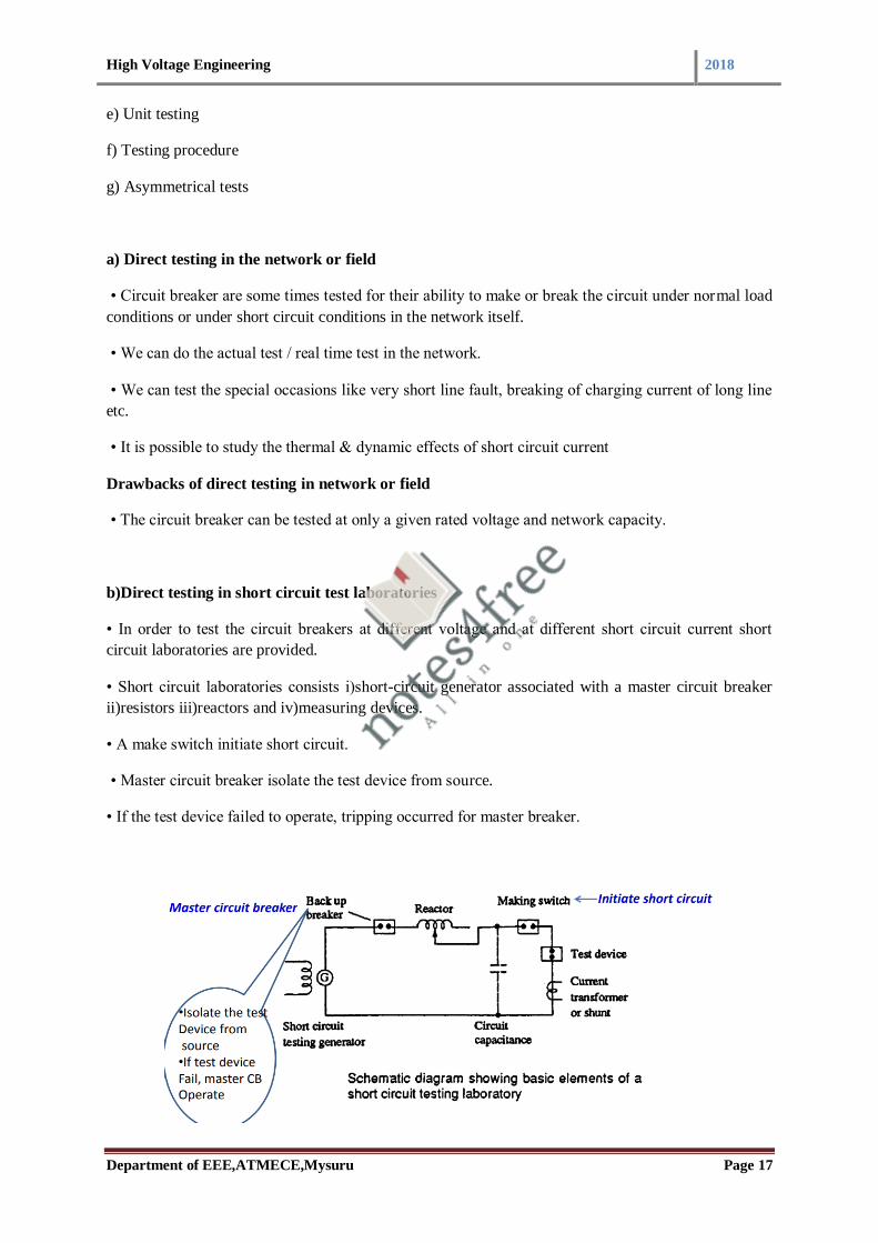
High Voltage Engineering 2018
Department of EEE,ATMECE,Mysuru Page 17
e) Unit testing
f) Testing procedure
g) Asymmetrical tests
a) Direct testing in the network or field
• Circuit breaker are some times tested for their ability to make or break the circuit under normal load
conditions or under short circuit conditions in the network itself.
• We can do the actual test / real time test in the network.
• We can test the special occasions like very short line fault, breaking of charging current of long line
etc.
• It is possible to study the thermal & dynamic effects of short circuit current
Drawbacks of direct testing in network or field
• The circuit breaker can be tested at only a given rated voltage and network capacity.
b)Direct testing in short circuit test laboratories
• In order to test the circuit breakers at different voltage and at different short circuit current short
circuit laboratories are provided.
• Short circuit laboratories consists i)short-circuit generator associated with a master circuit breaker
ii)resistors iii)reactors and iv)measuring devices.
• A make switch initiate short circuit.
• Master circuit breaker isolate the test device from source.
• If the test device failed to operate, tripping occurred for master breaker.

High Voltage Engineering 2018
Department of EEE,ATMECE,Mysuru Page 18
c)Synthetic testing of circuit breaker
• Two sources are used
• One supply provide ac current and other supply provide high voltage.
• Current and recovery voltage waveforms across the test circuit breaker can be determined using this
test
d)Composite testing
1. The breaker is tested under rated voltage level.
2. The breaker is tested under reduced voltage level for checking breaking capacity.
• Drawback:
This method doesn’t give the proper information about circuit breaker performance.
e)Unit testing
• Large circuit breaker testing under high voltage.
• Above 220kV system.
• More than 1 break is provided per pole.
• Checking the conditions of arc.
• Study the features of arc between fixed and moving contacts.
f)Asymmetric tests
• One test cycle is repeated for asymmetrical breaking capacity.
• Checking dc component in between fixed and moving contact.
• Test condition: dc component at the instant of contact separation is not less than 50% of AC
component.

High Voltage Engineering 2018
Department of EEE,ATMECE,Mysuru Page 19
5.3Testing of Cables
• Importance of cables & its insulation- Underground cable and power transmission.
• Transmitting voltage signals.
• Necessity of cable insulation testing.
Types of cable insulation testing
1. Mechanical tests like bending test, dripping test, drainage test , fire resistance and corrosion test.
2.Thermal duty test
3.Dielectric power factor test
4.Power frequency with standing capacity
5.Impulse with stand voltage test
NOTE: 4 and 5 are HV Tests
6.Partial discharge test
7.Life expectancy test
Initial step –preparation of cable samples
1. In order to prepare over voltage withstand test sample have to prepare very carefully.
2. Otherwise excessive leakage or flash over occur during testing.
3. The normal length of the cable samples varies from 50cm to 10m.
4. The termination are usually made shielding of the end conductor with stress shield

High Voltage Engineering 2018
Department of EEE,ATMECE,Mysuru Page 20
1.Dielectric power factor test
1. By using the HV Schering bridge.
2. Dissipation factor tanδ is measured at 0.5,1,1.66 & 2 times of the rated voltage of the cable.
3. Schering bridge has to be given protection against overvoltage , in case breakdown occur in
the cable.
4. balance equation is independent of frequency
2.HV Test on cable
a)Power frequency withstand voltage test
b) Impulse voltage with stand voltage test
Cables are tested for with stand the voltage using the power frequency AC, DC & Impulse voltage.
1. At a time of manufacture entire cable is tested under HV for checking continuity of the cable.
procedure
2. (i) First cable is tested under AC voltage of 2.5 of rated voltage for 10 minutes & no damage
should occur.
3. (ii) After cable is tested under high voltage dc voltage. DC voltage test consist of applying
1.8 times of rated voltage for 30 minutes.
4. (iii) Impulse voltage of the prescribed magnitude as per specification is applied & the cable
has to withstand five applications without any damage.
5. Ensure no failure occur during insulation
3.Partial Discharge Test
1. Partial discharge depends upon internal discharge, electric stress and voltage stress. •
2. Procedure:(a) Discharge detection , (b) location of discharge & (c) Scanning methods are
important steps of partial discharge test for ensuring the life of insulation.
(a) Discharge detection
1. The cable is connected to the discharge detector through the coupling capacitor.
2. Passage of travelling wave one or two times.
3. Check the cavity by analyze the nature of travelling wave.

High Voltage Engineering 2018
Department of EEE,ATMECE,Mysuru Page 21
4. In order to improve transient response the given circuit is applicable Considering more
number of cable & transient response
5. Serious error can detect • Error depends upon the shape of detector
6. Testing of long cable
(b) Location Discharge
1. Travelling wave is passing through the cable.
2. If any void present inside the cable ,there will be drop in travelling wave.
3. Measure the duration of wave/ pulse & the distance at which the discharge taking place from
the cable can be calculated.
4. The shape of wave/pulse depends upon the nature of discharge.
5. We can observe the attenuation of the travelling wave.

High Voltage Engineering 2018
Department of EEE,ATMECE,Mysuru Page 22
Location Discharge- detection circuits for long cable
Verification of location discharge

High Voltage Engineering 2018
Department of EEE,ATMECE,Mysuru Page 23
(c) Scanning method
1. To scan the overall cable for checking the voids or imperfections in manufacture. procedure
2. (i) Bare core cable is passed through high electric field & discharge location is done.
3. (ii) The core of the material is passed through a tube of insulating material filled with
distilled water.
4. 4 electrodes in the form of rings are arranged
5. They should have electrical contact with water
6. We can check where exactly the occurrence of discharge
7. Discharge can locate at the length of the cable
8. The defective part can be easily isolate by using this method.
9. Can increase the perfection of insulation production.
10. Can isolate the defective insulation at factory site.
(d) Life tests
1. Reliability studies.
2. Able to determine the expected life of insulation.
3. Cables are performed under normal stress and maximum stress.
4. It is established that the relation between the maximum electrical stress Em and the life of the
cable insulation in hours ‘t’ approximately follows the relationship
5. The duration of life tests is about 1 hr to 1000 hrs

High Voltage Engineering 2018
Department of EEE,ATMECE,Mysuru Page 24
5.3.1Testing of transformers
Importance of transformer testing
1. Transformer is Important & costly apparatus in power systems.
2. Great care has to be exercised to see that the transformers are not damaged due to transient
overvoltage's of either lightning or power frequency.
3. overvoltage tests become very important in the testing of transformers.
4. Mainly concentrating the overvoltage test.
5. Other tests are temperature rise test, short circuit test etc.
6. Performance test- OC-SC test, sumpners test(Back to back test) etc
Types of transformer testing
1.Preliminary testing- To check core insulation level
2.Routine Tests- Measurement of insulation resistance
3.Type test- Temperature rise test 4.Dielectric Test
5.Over Voltage Test- Induced over voltage test & Partial Discharge Test 6.Impulse Testing of
Transformers
1. Preliminary testing
• After the core is assembled, 2kV test is done to ensure that the insulation between clamp plates, core
bolts and core is adequate.

High Voltage Engineering 2018
Department of EEE,ATMECE,Mysuru Page 25
2. Routine Test
1. To measure winding insulation resistance
2. Measurement of Insulation resistance using ‘ Megger’.
3. The ‘Megger’ consists of a D.C power source (hand operated or electrically driven D.C
generator or a battery source with electronic circuit ) and a measuring system.
4. The insulation test reveals the condition of the insulation inside the transformer.
5. The insulation resistance values are affected by temperature, humidity and presence of dirt on
insulators and bushings.
3.Type test- Temperature rise test •
1. Purpose: to confirm that under normal conditions, the temperature rise of the windings and
the oil will not exceed the specified limit.
2. Temperature rises are measured above the temperature of the cooling air – Air cooled
transformers
3. In water cooled transformers, the temperature rise is measured above the inlet water
temperature – Water cooled type transformers
4. Hourly readings of the oil temperatures are taken.
5. Thermometer placed in a pocket in the transformer top cover.
6. Temperature at inlet and outlet of the cooler bank is also taken hourly and mean oil
temperature is determined.
7. Ambient temperature is measured.
8. It should be demonstrated that the top oil temperature rise does not vary more than 1 degree
Celsius per hour during four consecutive hourly readings.
9. The last reading is taken for the determination of the final oil temperature rise.
4. Dielectric Test
1. Purpose – to verify the power frequency withstand strength of the winding Insulation under
test
2. The full AC test voltage shall be applied for 60s to the Windings with graded insulation. •
3. The test shall be successful if no collapse of the test voltage occurs.
5. Overvoltage tests
(i) Induced over voltage test:
1. Purpose : To verify the power frequency withstand strength along the winding under test,
between its phases, and to earth and other windings. This test checks the inter turn insulation.
2. Test voltage is twice the corresponding rated voltage.
3. Supply frequency 100 to 400 Hz higher than normal is used.
4. The insulation withstand strength can be checked by using Induced Over Voltage Testing
(ii) Partial Discharge test:
1. Partial discharge tests on the windings are done to calculate the discharge magnitude and the
radio interference levels.
2. The winding insulation can be tested using any of the discharge detection methods..

High Voltage Engineering 2018
Department of EEE,ATMECE,Mysuru Page 26
3. The location of the fault or void is sometimes done by using the travelling wave technique
similar to that for cables.
4. No method has been standardized as to where the discharge is to be measured.
5. Under the application of power frequency voltage, the discharge magnitudes greater than
10^4 pico coulomb are considered to be severe.
6. The transformer insulation should be such that the discharge magnitude will be far below
this value.
6. Impulse testing of transformers
1. Lightning – common cause of flashover on overhead transmission lines.
2. Lightning stroke makes direct contact with a phase conductor and produces a voltage in
excess of impulse voltage level.
3. The purpose of the impulse tests is to determine the ability of the insulation of the
transformers to withstand the transient voltages due to lightning, etc.

High Voltage Engineering 2018
Department of EEE,ATMECE,Mysuru Page 27
Detection and fault location during impulse voltage testing of transformer
1. Can use any of the following methods
1. General observations
2. Voltage oscillogram method
3. Neutral current method
4. Transferred surge current method
1. General observations
• The fault can be located by general observations like noise in the tank or smoke or bubbles in
breather
2. Voltage oscillogram method
• Fault or failure appears as a partial or complete collapse of the applied voltage wave.
• The sensitivity of this method is low
3. Neutral current method
• In the neutral current method, a record of the impulse current flowing through a resistive shunt
between the neutral and ground point is used for detecting the fault.
4. Transferred surge current method
• In this method, the voltage across a resistive shunt connected between the low voltage winding and
the ground is used for fault location.
Testing of Bushings

High Voltage Engineering 2018
Department of EEE,ATMECE,Mysuru Page 28
(A) Power frequency test: Power Factor—Voltage Test – using schering bridge Internal or Partial
Discharge Test – Any methods for measuring partial discharge Momentary Withstand Test at Power
Frequency- Based on IS:2099 specification, Duration – 30s One Minute Wet Withstand Test at Power
FrequencyDuration 1 minute, Provide rain /moisture Visible Discharge Test at Power Frequency-
Dark room, Based on IS:2099 specification & observe discharge
(B) Impulse Voltage Testing: • Full Wave Withstand Test- Five consecutive full waves of standard
waveform are applied, if two of them cause flashover, the bushing is said to have failed in the test. •
Chopped Wave Withstand and Switching Surge Tests- HV test, procedure is same as that of Full
Wave Withstand Test
(C) Thermal Tests: Temperature Rise and Thermal Stability Tests
• Temperature rise test is carried out in free air with an ambient temperature below 400 degree C at a
rated power frequency (50 Hz) AC current.
• The test is carried out for such a long time till the temperature is substantially constant, i.e. the
increase in temperature rate is less than l°C /hr.
Course Outcome:
At the end of the course, students will be able to:
Discuss non-destructive testing of materials and electric apparatus and high-voltage testing of electric apparatus