modulator 255253h
TRANSCRIPT

7/23/2019 Modulator 255253H
http://slidepdf.com/reader/full/modulator-255253h 1/21
MODULATOR SERIES
SPEAKER ARRAYS
INSTALLATION AND MAINTENANCE INSTRUCTIONS
255253H 1/02

7/23/2019 Modulator 255253H
http://slidepdf.com/reader/full/modulator-255253h 2/21
i
SAFETY NOTICES
People’s lives depend on your safe installation, service, and
operation of our products. It is important to read, understand and
follow all instructions shipped with this product. In addition, listed
below are some other important safety instructions and precautions
you should follow:
INSTALLATION & SERVICE
! Electrocution or severe personal injury can occur when performing
various installation and service functions such as making electrical
connections, drilling holes, or lifting equipment. Therefore
installation should be performed by experienced electricians in
accordance with national, state and any other electrical codes having
jurisdiction. All work should be performed under the direction of the
installation or service crew safety foreman.
! The sound output of sirens is capable of causing permanent hearing
damage. To prevent excessive exposure, carefully plan siren
placement, post warnings and restrict access to areas near the sirens.
Whenever possible, disconnect the siren batteries before workingnear the speaker array.
! After installation or service, test the siren system to confirm that it is
operating properly. Test the system regularly to confirm that it will
be operational in an emergency.
! If future service personnel do not have these warnings and all other
instructions shipped with the equipment to refer to, the siren system
may not provide the intended audible warning and service personnel
may be exposed to death, permanent hearing loss, or other bodily
injury. File these instructions in a safe place and refer to them
periodically. Give a copy of these instructions to new recruits and
trainees. Also, give a copy to anyone who is going to service or repairthe sirens. For additional copies, call the Federal Signal Community
Warning Systems Group at 800-548-7229 or write to them at 2645
Federal Signal Drive, University Park, IL. 60466.
OPERATION
! Failure to understand the capabilities and limitations of your siren
system could result in permanent hearing loss, other serious injuries
or death to persons too close to the sirens when you activate them or
to those you need to warn. Carefully read and thoroughly understand
all safety notices on both sides of this sheet and all operations-related
items in all instruction manuals shipped with the equipment.
Thoroughly discuss all contingency plans with those responsible for
warning people in your community, company, or jurisdiction.

7/23/2019 Modulator 255253H
http://slidepdf.com/reader/full/modulator-255253h 3/21
ii
SAFETY NOTICES
People’s lives depend on your selection of suitable equipment and
installation sites and your safe installation, service, and operation of
our products. Follow Federal Emergency Management Agency
(FEMA) recommendations. Obtain copies of the latest revision of
FEMA’S Outdoor Warning Guide (CPG 1-17) and Civil Preparedness,
Principals of Warning (CPG 1-14) by calling FEMA at (202) 646-3484
or writing to them at 500 C Street SW, Washington, D.C. 20472. It isalso important to read, understand and follow all instructions
shipped with this product. In addition, listed below are some other
important safety instructions and precautions you should follow:
PLANNING
! If suitable warning equipment is not selected, the installation site
for the siren is not selected properly or the siren is not installed
properly, it may not produce the intended optimum audible
warning. Follow Federal Emergency Management Agency
(FEMA) recommendations.
! If the sirens are not activated in a timely manner when anemergency condition exists, they cannot provide the intended
audible warning. It is imperative that knowledgeable people, who
are provided with the necessary information, are available at all
times to authorize the activation of the sirens.
! When sirens are used out of doors, people indoors may not be able
to hear the warning signals. Separate warning devices or
procedures may be needed to effectively warn people indoors.
! The sound output of sirens is capable of causing permanent
hearing damage. To prevent excessive exposure, carefully plan
siren placement, post warnings, and restrict access to areas near
sirens.
! Activating the sirens may not result in people taking the desired
actions if those to be warned are not properly trained about the
meaning of siren sounds. Siren users should follow FEMA
recommendations and instruct those to be warned of correct
actions to be taken.
! A siren that doesn’t work won’t provide any warning. After
installation, servicing, or repair, test the siren system to confirm
that it is operating properly. Test the system regularly to confirm
that it will be operational in an emergency.
! If future service and operating personnel do not have these
instructions to refer to, the siren system may not provide the
intended audible warning and service personnel may be exposed
to death, permanent hearing loss, or other bodily injury. File
these instructions in a safe place and refer to them periodically.
Give a copy of these instructions to new recruits and trainees.
Also give a copy to anyone who is going to service or repair the
siren.

7/23/2019 Modulator 255253H
http://slidepdf.com/reader/full/modulator-255253h 4/21
iii
LIMITED WARRANTY
The Signal Division, Federal Signal Corporation (Federal), warrants
each new product to be free from defects in material and workman-
ship, under normal use and service, for a period of two years on parts
replacement and one year on labor from the date of delivery to the first
user-purchaser.
During this warranty period, the obligation of Federal is limited to
repairing or replacing, as Federal may elect, any part or parts of such
product, which after examination by Federal discloses to be defective
in material and/or workmanship.
Federal will provide warranty for any unit which is delivered,
transported prepaid, to the Federal factory or designated authorized
warranty service center for examination and such examination reveals
a defect in material and/or workmanship.
This warranty does not cover travel expenses, the cost of specialized
equipment for gaining access to the product, or labor charges for
removal and re-installation of the product. Batteries are not covered
under warranty.
This warranty does not extend to any unit which has been subjected to
abuse, misuse, improper installation or which has been inadequately
maintained, nor to units which have problems relating to service or
modification at any facility other than the Federal factory or
authorized warranty service centers.
THERE ARE NO OTHER WARRANTIES, EXPRESSED OR IM-
PLIED, INCLUDING BUT NOT LIMITED TO, ANY IMPLIED
WARRANTIES OF MERCHANTABILITY OR FITNESS FOR A PARTICULAR PURPOSE. IN NO EVENT SHALL FEDERAL BE
LIABLE FOR ANY LOSS OF PROFITS OR ANY INDIRECT OR
CONSEQUENTIAL DAMAGES ARISING OUT OF ANY SUCH DE-
FECT IN MATERIAL OR WORKMANSHIP.
IMPORTANT NOTICE:
Federal Signal reserves the right to make changes to devices and
specifications detailed in this manual at any time in order to improve
reliability, function or design. The information in this book has been
carefully checked and is believed to be accurate; however no responsi-
bility is assumed for any inaccuracies.

7/23/2019 Modulator 255253H
http://slidepdf.com/reader/full/modulator-255253h 5/21
iv
TABLE OF CONTENTS
Paragraph Page
SECTION I – CHARACTERISTICS
1-1 Scope of this Manual.................................................................................................. 1-1
1-2 General ....................................................................................................................... 1-1
1-3 Siren Description ....................................................................................................... 1-1
1-4 Frequency Response .................................................................................................. 1-1
1-5 Features ..................................................................................................................... 1-1
SECTION II - SPECIFICATIONS
2-1 Siren............................................................................................................................ 2-1
SECTION III – INSTALLATION
3-1 Siren Location ............................................................................................................ 3-1
3-2 Siren Installation ....................................................................................................... 3-2
3-3 Speaker Connections ................................................................................................. 3-4
3-4 Pre-operation Checkout............................................................................................. 3-6
SECTION IV - SERVICE AND MAINTENANCE
4-1 General ....................................................................................................................... 4-1
4-2 Preventive Maintenance............................................................................................ 4-1
4-3 Driver Replacement ................................................................................................... 4-1

7/23/2019 Modulator 255253H
http://slidepdf.com/reader/full/modulator-255253h 6/21
1-1
SECTION I
CHARACTERISTICS
Figure 1-1. Modulator series Outline Drawing
1-1. SCOPE OF THIS MANUAL.
This service manual describes the
characteristics, specifications, installation,
theory of operation, and service and
maintenance of the Federal Modulator Series
Outdoor Warning Siren speaker arrays.
1-2. GENERAL.
Federal Signal’s Modulator Series
Siren products are a family of electronic sirens
that are capable of producing high intensity
warning signals over a large area. The siren
consists of a speaker array (figure 1-1) and a
control unit/battery box. A highly efficient
design enables the siren to produce a high
sound level, while making moderate demands
on the power source.
1-3. SIREN DESCRIPTION.
Federal Signal’s innovative omnidirectional,
electronic Modulator siren series consist ofaluminum modules that utilize four 100 watt
drivers per module. The Modulator series is
available in several models which have the
following sound output rating at 100 feet.*
MOD1004 106dBC
MOD2008 112dBC
MOD3012 115dBC
MOD4016 118dBC
MOD5020 120dBC
MOD6024 121dBC
MOD6048 125dBC
*Based on measurements at 500 feet.
1-4. FREQUENCY RESPONSE.
The Modulator Series siren provides
virtually flat frequency response from 200 -
2000 Hertz. This gives the siren the ability to
produce loud and clear voice messages as well
as the ability to produce a full spectrum of
warning tones.
1-5. FEATURES.
An UltraVoice Series control unit
(UV) is needed for complete operation.

7/23/2019 Modulator 255253H
http://slidepdf.com/reader/full/modulator-255253h 7/21
2-1
SECTION II
SPECIFICATIONS
2-1. SIREN.
Color ....................................................................Weather Guard White II
Paint Type ..............................................................TGIC Polyester Powder coat
Modular Horn Type ...............................................Hyperbolic Flare
Frequency Response ..............................................200 - 2000 Hz.
Horizontal Coverage ..............................................360 Degree
Bottom (non-active) Module*
Dimensions................................................15-1/2 x 44-1/2" Diameter
(See Fig. 1-1)
MOD1004
Number of Active Modules.......................1
Power .........................................................400 Watts
dB output...................................................106 dBC @100 feet
Height of Speaker Array ..........................43.17"
Weight .......................................................181 lbs.
MOD2008
Number of Active Modules.......................2
Power .........................................................800 WattsdB output...................................................112 dBC @100 feet
Height of Speaker Array ..........................63.70"
Weight .......................................................296 lbs.
MOD3012
Number of Active Modules.......................3
Power .........................................................1200 Watts
dB output...................................................115 dBC @ 100 feet
Height of Speaker Array ..........................84.30"
Weight .......................................................411 lbs.
MOD4016
Number of Active Modules.......................4
Power .........................................................1600 Watts
dB output...................................................118 dBC @ 100 feet
Height of Speaker Array ..........................105.00"
Weight .......................................................526 lbs.

7/23/2019 Modulator 255253H
http://slidepdf.com/reader/full/modulator-255253h 8/21
2-2
MOD5020
Number of Active Modules.......................5
Power .........................................................2000 Watts
dB output...................................................120 dBC @ 100 feet
Height of Speaker Array ..........................125.50"
Weight .......................................................640 lbs.
MOD6024
Number of Active Modules.......................6
Power .........................................................2400 Watts
dB output...................................................121 dBC @ 100 feet
Height of Speaker Array ..........................146.08"
Weight .......................................................760 lbs.
MOD6048
Number of Active Modules.......................6
Power .........................................................4800 Watts
dB output...................................................125 dBC @ 100 feetHeight of Speaker Array ..........................146.08"
Weight .......................................................928 lbs.
*The bottom module of the siren is a passive device that does not contain any drivers.
Its functional use is to complete the horn formed by the bottom and the first active module.

7/23/2019 Modulator 255253H
http://slidepdf.com/reader/full/modulator-255253h 9/21
3-1
SECTION III
INSTALLATION
DANGER
Electrocution or severe
personal injury can occur
when making electrical
connections, drilling holes,
or lifting equipment.
Therefore, installation
should be performed by
experienced electricians in
accordance with national
and local electrical codes.
3-1. SIREN LOCATION.
The information in this section
provides guidelines to aid the user in the
selection of an installation site that makes the
best possible use of the siren.
WARNING
The output level of a
Modulator Series Siren is
capable of causing
permanent hearing
damage. To preventexcessive exposure,
carefully plan placement of
siren and post warnings.
If the siren is being installed as part
of a Civil Defense Warning system, ALWAYS
follow Federal Emergency Management
Agency (FEMA) recommendations.
Careful consideration of the factors
affecting the propagation of sound from the
siren and the response of the human ear tothe sound will optimize the ability of the siren
to effectively warn the community outdoors.
The reduction of signal intensity, as
the distance from the siren increases and the
minimum desired signal level at the fringe of
the outdoor area to be covered are important
considerations when choosing a siren
installation site. As the distance from the
siren increases, sound level losses accumulate.These losses are a result of weather
conditions, the terrain, obstructions in the
sound path, the pitch of the sound and the
height of the siren.
Optimum sound propagation
conditions exist when there are no
obstructions in the sound path, the terrain is
flat, and the air is calm. Under these
conditions, each time the distance from the
siren is doubled, the sound level decreases by
approximately 10dB. For example, the sound
level at 100 feet (30.5m) from a MOD6024 is121dB. At 200 feet (61m), the level drops to
111dB; at 400 feet (122m) the sound level
drops to 101dB; etc. This is referred to as the
“loss per distance doubled”.
A loss per distance doubled of 10dB is
usually experienced because buildings and
other obstructions are frequently present in
the sound path. In addition, the atmosphere is
rarely calm, the terrain may not be flat, and
humidity conditions may vary. As a result, a
typical loss per distance doubled in residentialareas may be 10dB, and as high as 12dB in
areas having tall buildings or other factors
detrimental to sound propagation. Ideally in a
free field, the loss would be 6dB per distance
doubled.
Experience indicates an individual
with normal hearing will probably hear a
warning signal whose intensity is at least as
high as the ambient noise level.
Experience has also shown that the
ambient outdoor noise level in industrialdistricts is typically 90dB. Therefore, for a
person to hear a warning signal in an
industrial area, the sound level intensity of
that signal must also be at least 90dB. In this
situation, any point receiving a signal having
less than 90dB intensity is considered to be
outside the effective range of the siren.

7/23/2019 Modulator 255253H
http://slidepdf.com/reader/full/modulator-255253h 10/21
3-2
In business districts an ambient
noise level of 80dB is common, and in
residential areas, 68dB of ambient noise is
typical. Assuming a 10dB loss per distance
doubled and a 68dB minimum sound level, the
effective range of the MOD6024 is
approximately 3900 feet.
Wind speed and direction often affect
the propagation of sound from the siren.
Consequently, the direction of the prevailing
wind may also be a factor to consider when
selecting the installation site(s) of a small, one
or two-siren system. For example, if the
prevailing wind is from the west, it may be
desirable to install the siren toward the
western edge of the area to be covered.
Other factors to consider before
selecting the installation site include theavailability of electrical power, the ease of
installation and maintenance, the height of
surrounding obstructions, and security
against vandalism.
3-2. SIREN INSTALLATION.
A. General.
Most siren installations are one of
two types: Pole Mount or Flat Surface Mount.These two configurations make it possible to
install a siren in almost any situation. If the
installations in this paragraph are not
suitable, modification of one of the
configurations may be practical.
A siren is typically installed 40 - 50
ft. above the ground. If the installation is
located less than 50 ft. above the ground, the
sound intensity at close range may increase,
but at the same time the effective range of the
siren may be reduced. Conversely, if the sirenis located more than 50 ft. above ground, the
effective range of the siren may increase, but
the sound may skip over areas closer to the
siren. These variables may make it desirable
to test the sound coverage of the siren at
various heights and locations whenever
possible.
B. Pole Mounting.
(CUSTOMER SUPPLIED)
GROUND LEVEL
CONCRETE FOOTING OPTIONAL
CONTRACT SPECIFICATIONS DETERMINE
AND NATIONAL ELECTRICAL BUILDING CODESBEFORE PROCEEDING WITH INSTALLATION.
INSTALLATION ALWAYS REFER TO LOCALNOTE: DRAWING DEPICTS A TYPICAL
NOTE: CERTAIN SOIL CONDITIONS MAYREQUIRE GUYING FOR THE POLE.
CLASS II UTILITY POLE
(CUSTOMER SUPPLIED)
(CUSTOMER SUPPLIED)
GROUND ROD TO BE 8 FT.#4 COPPER WITH CLAMP
1-1/4" CRANE LIFT HOLE(CONTROL UNIT & BATTERY BOX)
ULTRAVOICE CONTROL
CONTROL UNIT GROUND WIRE
BATTERY BOX
SERVICE DISCONNECT
BETWEEN ANGLE LEGS & POLE.
(CUSTOMER SUPPLIED)
(CUSTOMER SUPPLIED)(IF REQUIRED)
INSTALL 5/8" LAG BOLTS & SHIMS
(CUSTOMER SUPPLIED) AS REQUIRED
SPEAKER ASSEMBLY GROUNDWIRE, #4 COPPER, CONNECT
RADIO ANTENNA (IF REQ'D)
TO GROUND ROD DIRECTLY.
CONDUIT & CLAMPS(CUSTOMER SUPPLIED)
40' SPEAKER CABLE (LONGER OPTIONAL)(FEDERAL SUPPLIED)
CRANE LIFT EYEBOLT
100W DRIVER (4 PER ACTIVE CELL)
(SHOWN POLE MOUNTED)
MOD6024
DRIVER ACCESS DOOR(4 PER ACTIVE CELL)
291275B
Figure 3-1. Typical Pole-mounted Installation
A typical pole-mounted siren
installation is shown in figure 3-1. The siren is
mounted on a Class 2 utility pole (ANSI type
wooden pole or equivalent) with a minimum
horizontal ground stress rating of 3,700
pounds (1682 Kg). (Insure that soil loads will

7/23/2019 Modulator 255253H
http://slidepdf.com/reader/full/modulator-255253h 11/21
3-3
conform to this size utility pole). It is
attached to the pole by means of legs, as
shown in figure 3-2.
1/2-13 HEX NUTS (8)
SPLIT LOCKWASHERS (8)
1/2-13 HEX HD. BOLTS (8)
LEGS (4)
MODULATOR SIREN
BASE PLATE
LEGS (4)
SEE DETAILBELOW
291274A
Figure 3-2. Siren Leg Assembly
Using the 3 ft. long angle iron legs, the siren
is mounted on the Class 2 utility pole as
follows:
1. Uncrate the siren and remove
the nuts that hold the siren on the shipping
base. Lift the siren approximately 3-1/2 ft.
with a crane or hoist.
2. Install the four legs on the siren
mounting plate, as shown in figure 3-2. Use
two 1/2" bolts, nuts and lockwashers
(provided) for each leg. Do not tighten thebolts completely.
WARNING
The eyebolt does NOT
have sufficient strength to
support the combined
weight of the siren and a
utility pole. Therefore, do
NOT attempt to erect the
pole and siren together
using the eyebolt as a
lifting point.
3. Erect the utility pole in
accordance with accepted practices and FEMA
guidelines.
4. Raise the siren to the necessary
height, and lower it over the pole. Maintain
tension on lifting chain until all bolts are
tightened.
5. Adjust the legs and insert shims,
if necessary, between the siren legs and pole.
Bolt the siren to the pole using two user
supplied 5/8" lag bolts, at least four incheslong for each leg. Tighten all bolts, including
those from step 2 above.
C. Flat Surface Mount.
This installation configuration is
practical when the installation site is on a flat
roofed building. The siren can be anchored
directly to the roof, on a platform as shown in
figure 3-3, or on a weight distribution mat like
the one shown in figure 3-5.
This mat is required when the siren
mounting surface is unable to support over
176 pounds per square foot (859kg per square
meter). The mat shown in figure 3-5
distributes the siren weight to approximately
25 pounds per square foot (122kg per square
meter). When installing the siren on a flat
roof, be sure that it clears the parapets or
other obstructions by at least ten feet.
To install a Modulator Series Siren
on a flat roof or other flat surface, proceed as
follows:
1. If desired, construct a platform
for mounting the siren, which must be capable
of supporting at least 800 lbs. as well as
withstanding a siren wind load of 100 mph.
The platform must also be capable of
distributing its own weight plus the siren to a
value that is safe for the mounting surface.

7/23/2019 Modulator 255253H
http://slidepdf.com/reader/full/modulator-255253h 12/21
3-4
Platform design and construction details are
left to the installer. Locate the platform at the
siren installation site. Using suitable
hardware (not supplied), anchor the platform
to the mounting surface.
CONTROL
291276B
(IF REQUIRED)
PLATFORM *
TO INSTALLATION.
AND METHODS PRIOR
MOUNTING LOCATIONS
* A PROFESSIONAL/
STRUCTURAL ENGINEER
SHOULD REVIEW
ROOF MEMBERS
INTO PLATFORM AND
DISCONNECT
DEVICE
TO POWER SOURCE
TO CONTROL
SEAL IF WIRING PASSES THROUGH WALL OR ROOF
SERVICE
BATTERIES
ULTRAVOICE
SEE DETAIL "A"
ANCHOR LAG SCREWS
WOOD OR STEEL
CONDUIT
ROOF
CRANE LIFT
8 TO 10 FT.
Figure 3-3. Typical Surface-mounted Siren Installation
WARNING
The eyebolt and hoisting
bracket do not have
sufficient strength to
support the combined
weight of the siren and theplatform. Therefore, do
NOT lift the siren and
platform together using the
eyebolt as a lifting point.
2. Hoist the siren to the
installation site using the eyebolt as a lifting
point (refer to WARNING above).
291277A
3.49
9.00
3.49
3.49
2.39
18.00
90°
4X 1.62
4X 45°
4X 2.47
4X 4.94
2.39
9.00
6.233.49
18.006.23
Ø23.25
20X Ø0.56
Figure 3-4. Siren Base Plate
3. Anchor the siren to the
mounting surface with a user supplied 1/2" lag
bolts or nuts and bolts, as appropriate throughthe mounting holes (one in each corner) in the
siren base plate (see figure 3-4). If the siren is
mounted directly on a roof, (without a
platform or weight distribution mat) be sure
to install user supplied waterproof joints at
the points where the mounting bolts pass
through the roof so that water does not enter
the building.
Figure 3-5.Weight Distribution Mat Construction.
3-3. SPEAKER CONNECTIONS.
Depending on the model of siren usedthe number of speaker connections and colors
will vary. This is due to the different number
of drivers required for each model. In either
case OBSERVE PROPER POLARITY when
making these connections. The striped wire is
common and goes to position 2. The solid
colored wire is signal high and goes to position
1. Each speaker connection is color coded.

7/23/2019 Modulator 255253H
http://slidepdf.com/reader/full/modulator-255253h 13/21
3-5
Refer to the table below for wiring and
position.
6
5
A - 2 A - 1 BROWN
WHT(JUMP)
TERMINALDRIVER-
COLORWIRE
4
3
2
1
MODULE ACTIVE
DRIVER ORIENTATION
TOP VIEW
1
21
2
21
2 1
C
B
D
A
291278B
WHT(J
UMP)
B R N
WHT (JUMP)
BRN
WHT/BRN
/ /B - 2/B - 1 WHT(JUMP)/WHT/BRN
WHT/BRNWHT(JUMP)/C - 2/C - 1
BROWN/WHT(JUMP)D - 2D - 1 /E - 1
WHT(JUMP)RED/E - 2/
H - 2
G - 2
F - 2F - 1 /
H - 1
G - 1 //
WHT/RED
WHT(JUMP)
WHT/REDWHT(JUMP)
RED
WHT(JUMP)
///
L - 2
K - 2
J - 2
I - 2I - 1 /
L - 1 /
K - 1
J - 1
//
ORANGE/WHT/ORG
WHT/ORG
WHT(JUMP)
WHT(JUMP)
ORANGE
WHT(JUMP)
WHT(JUMP)
///
P - 2
O - 2
N - 2
M - 2
/P - 1 /
O - 1
N - 1
M - 1
//
WHT/YEL
WHT/YEL
WHT(JUMP)
WHT(JUMP)
/YELLOW /
YELLOW
WHT(JUMP)
WHT(JUMP)
//
Q - 1
T - 2
S - 2
R - 2
Q - 2
/
/T - 1S - 1
/
R - 1
/
WHT/GRN
WHT/GRN
WHT(JUMP)
WHT(JUMP)
GREEN
GREEN
WHT(JUMP)
WHT(JUMP)/
//
/
V - 1 /WHT(JUMP)/
X - 2
W - 2
V - 2
X - 1
W - 1 //
WHT/BLU
WHT/BLU
WHT(JUMP)BLUE
WHT(JUMP)//
U - 2U - 1 / WHT(JUMP)
BLUE /
W H T / B R N
12
D
2 1
C
1 2
C1
2
B
2
1
1 2
DRIVER ORIENTATION
A B
D2
A
1
2
1
WHT/BLU
6X - 2W - 1
V - 2U - 1
P - 2
5T - 2S - 1
R - 2Q - 1
4N - 2
O - 1
M - 1
L - 2
WHT/BLK
WHT/PNK
BLACK
PINK
WHT/GRY
WHT/TAN
BLK/WHTWHITE
TAN
WHT/VIOVIOLET
GRAY
TERMINALDRIVER-
1
G - 1
3I - 1
K - 1
J - 2
H - 2
2F - 2E - 1
D - 2C - 1
MODULE ACTIVE
B - 2 A - 1
YELLOW
BLUE
WHT/YEL
WHT/GRNGREEN
ORANGE
WHT/RED
WHT/ORG
RED
BROWNWHT/BRN
COLORWIRE
WIRE THE FOLLOWING DRIVERS DIRECTLY ABOVE DRIVERS A & B:
(FIRST ACTIVE MODULE - MOD6048 ONLY)
E & F, I & J, M & N, Q & R. AND U & V.
R E D
W H T
/ R E D
RED
WHT/RED
WHT/BRN
BRN
B R N
W H T
/ B R N
291279A
Figure 3-6. Driver Orientation
7/23/2019 Modulator 255253H
http://slidepdf.com/reader/full/modulator-255253h 14/21
3-6
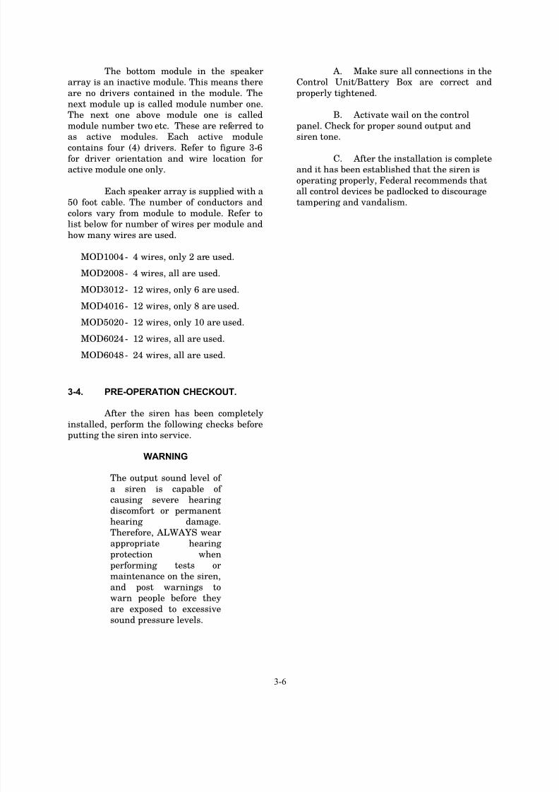
The bottom module in the speaker
array is an inactive module. This means there
are no drivers contained in the module. The
next module up is called module number one.
The next one above module one is called
module number two etc. These are referred to
as active modules. Each active modulecontains four (4) drivers. Refer to figure 3-6
for driver orientation and wire location for
active module one only.
Each speaker array is supplied with a
50 foot cable. The number of conductors and
colors vary from module to module. Refer to
list below for number of wires per module and
how many wires are used.
MOD1004 - 4 wires, only 2 are used.
MOD2008 - 4 wires, all are used.MOD3012 - 12 wires, only 6 are used.
MOD4016 - 12 wires, only 8 are used.
MOD5020 - 12 wires, only 10 are used.
MOD6024 - 12 wires, all are used.
MOD6048 - 24 wires, all are used.
3-4. PRE-OPERATION CHECKOUT.
After the siren has been completelyinstalled, perform the following checks before
putting the siren into service.
WARNING
The output sound level of
a siren is capable of
causing severe hearing
discomfort or permanent
hearing damage.
Therefore, ALWAYS wear
appropriate hearing
protection whenperforming tests or
maintenance on the siren,
and post warnings to
warn people before they
are exposed to excessive
sound pressure levels.
A. Make sure all connections in the
Control Unit/Battery Box are correct and
properly tightened.
B. Activate wail on the control
panel. Check for proper sound output and
siren tone.
C. After the installation is complete
and it has been established that the siren is
operating properly, Federal recommends that
all control devices be padlocked to discourage
tampering and vandalism.
7/23/2019 Modulator 255253H
http://slidepdf.com/reader/full/modulator-255253h 15/21
4-1
SECTION IV
SERVICE AND MAINTENANCE
4-1. GENERAL.
WARNING
Service or maintenance
should be performed by
qualified personnel
familiar with the siren,
associated controls, and
power sources being used.
The sound output of the
siren is capable of causing
permanent hearing
damage. Use adequatehearing protection and
avoid excessive exposure.
Before servicing or
maintaining, ensure that
remote activation cannot
occur and disconnect
power to the siren and its
controls.
The Modulator Series Siren is
designed to require a minimum of
maintenance. In addition, experience has
shown that all Federal sirens are highly
reliable devices. However, if a siren failure
does occur, Federal will provide technical
assistance with problems that cannot be
handled satisfactorily and promptly locally. If
assistance is desired, contact:
CWS Service Department
Signal Division
Federal Signal Corporation
2645 Federal Signal Drive
University Park, Illinois 604661 (800) 548-7229
WARNING
The output level of a
Modulator Series Siren is
capable of causing
permanent hearing
damage. Therefore,
ALWAYS wear hearing
protection when
performing tests or
maintenance on the siren.
To prevent the siren from
sounding always turn off
the power to the siren at
the disconnect switch and
remove any DC power
being supplied by the
Battery Box beforeinspecting or maintaining
the siren.
4-2. PREVENTIVE MAINTENANCE.
Test the Siren for proper operation at
least once a month. A daily test at noon,
curfew, or other selected time is preferred.
This not only enhances the usefulness of the
siren and verifies that it remains ready for use
in an emergency, but instills public confidence
in the reliability of the warning system.
In order to minimize the possibility of
siren failure, annual inspection and
maintenance is desirable.
Perform a driver inspection as
described in Section 4-3.
4-3. DRIVER REPLACEMENT
To determine if a driver is bad refer to theprocedure outlined in the installation
instruction for the amplifier control unit or
remove the speaker circuit from the terminal
block and measure the impedance of the
circuit. The impedance will measure
approximately 2.7 ohms. If the reading is
higher (5.4 ohms) one driver is bad. If the

7/23/2019 Modulator 255253H
http://slidepdf.com/reader/full/modulator-255253h 16/21
4-2
circuit is open, then either both drivers are
bad, or a wire has been severed.
To determine the location of the bad driver
refer to the wiring table in section 3 and
figure 3-6.
To replace a defective driver remove the four
hex head 1/4 inch mounting bolts that are
holding the inspection plate. Make sure the
flat washer and split washer are not
misplaced. Note the color and location of the
wires going to the driver. Remove the wire
from the terminals on the driver. Remove the
driver by turning it counter clockwise. Add
new driver by turning it clockwise. Make sure
that the male threads are greased. Reconnect
the wires as previously noted. Reinstall theinspection plate.

7/23/2019 Modulator 255253H
http://slidepdf.com/reader/full/modulator-255253h 17/21

7/23/2019 Modulator 255253H
http://slidepdf.com/reader/full/modulator-255253h 18/21
4-4
FIRST ACTIVE
MODULE
NUT,1/2-13215 7059A077
BOLT,7",3/8-162
42
7004A005-97
7074A023
8291A027A
2561043A
255253H1
45 0
4
343
44 MANUAL
SHEET,CHECK LIST
LKWASH,SPLIT,3/8
BAG,PLASTIC,18X30
GASKET, DOOR46.68 FT28 R42-04-01
7072A148A
7099A103-15
81461331A-04
8570026A
150A146A
R70-08-03
R81-11-01
R72-02-01
7004A004-56
7057A032
7072A036
8291B016
135
2
38 4
4
140
41
39
1636
37
1631
2
16
3 OZ
33
34
32
.04 OZ
.0129
30
NAMEPLATE
BOLT,3/8-16 X 3-1
NUT,STL 3/8
WASHER,FLAT 3/8
BAG,POLY,14X16
WASH. FLT. NEOPRENE
RUBBER PAD
POP RIVET,1/8"
TIE WRAP
RTV, SILICONE
GREASE,CONTACT
LOCTITE
8570002A
8570011A
8570032A
161693A
175728C-04
7072A095
7072A024
8570010B
8570043A
8570006A
8570053A-01
7003A000-24
R42-02-08
122
325
18
3
226
27
1
11 FT
23
24
418
16
4
184
20
21
19
1
116
17
CABLE,SIREN
MODULE,TOP,ACTIVE
SPINNING,FEMALE
U GASKET, SPINNING
LABEL,FS
WASHER,FLAT,1/2"
NEOPRENE SPNG.STRIP
MOD4016B
MOD4016
HORN,MOLDED
WASH.FLAT,S.S.
SCREEN,HORNHORN THROAT
U BRACKET ASSY.
EYEBOLT
SPINNING,MALE MOD401643
8570001A
8570005A
8570042A
8570029A
8570001A-01
7074A025
7000A338-88
7058A010
7000A345-16
7074A067
7072A0388570014A
8619144A-01
8570008B-04
168
16811
2
16
213
14
12
152
19
10
165
16
1
16
6
7
1
14
GASKET,1" I.D.
SCREW,.25-20 S.S.
LKWSHR,SPLIT
SCREW,1/2-13
STOP-NUT,.25-20 S.S.
LKWSHR,SPLIT S.S.
WASHER,RUBBER
DOOR,ACCESS
DOOR,ACCESS
FS 100W DRIVER
PIPE,BASE ASSY.
MODULE,BOTTOM,INACTIVE
SPINNING,MALE
MOD4016B
MOD4016
MOD4016B
MOD4016
8570033A
8570031A
8570030A
8570002A-01
8570003A
PART NO.
PARTS LIST
MOD4016/MOD4016B
1
4
1
12
1
REQ'DITEM
1SPINNING,TOP
MODULE,BOTTOM,ACTICE
MODULE,TOP,INACTIVE
SPINNING,FEMALE
MODULE,TOP,SIRENDESCRIPTION
MOD4016
MOD4016
MOD4016B
MOD4016B
MODELMOD4016B
47 BRACKET ASSY,POLE MTG4
146 8549A083A
8549A170A
ACCY. KIT,MTG HDW
T-WIRE,46"WHT.T300214-09-009848
Figure 4-2. Model MOD4016/MOD4016B Parts Location Diagram.

7/23/2019 Modulator 255253H
http://slidepdf.com/reader/full/modulator-255253h 19/21
4-5
FIRST ACTIVE
MODULE
LKWSHR,SPLIT214 7074A025
BAG,POLY,14X161
41
8291B016
BAG,PLASTIC,18X30
LKWASH,SPLIT,3/8
BOLT,7",3/8-16
SHEET, CHECK LIST
8291A027A
7004A005-97
7074A023
255253H
2561043A
3
4445 0
1
4243
2
4
MANUAL
U GASKET, SPINNING2227 8570011A
WASH. FLT. NEOPRENE
WASHER,FLAT 3/8
BOLT,3/8-16 X 3-1
GASKET, DOOR
GREASE,CONTACT
RTV, SILICONE
RUBBER PAD
POP RIVET,1/8"34 2 7099A103-15
7072A148A
81461331A-05
7072A036
7004A004-56
7057A032
37
3940
38 4
4
2
3536
1
20
NUT,STL 3/8
NAMEPLATE
R42-04-01
R72-02-01
R81-11-01
R70-08-03
8570026A
150A146A
.05 OZ30
3233
313.75 OZ
20
20
2928
.01
58.34 FT
TIE WRAP
LOCTITE
MODULE,TOP,ACTIVE
NEOPRENE SPNG.STRIP
SPINNING,FEMALE
U BRACKET ASSY.
HORN,MOLDED
HORN THROAT
SCREEN,HORN
WASH.FLAT,S.S.
CABLE,SIREN
WASHER,FLAT,1/2"
22821 7072A024
R42-02-08
8570032A
8570002A
161693A
175728C-05
7072A095
26
254
2
4
2324
221
11 FT
1
LABEL,FS
7003A000-24
8570053A-01
7059A077
8570006A
8570043A
8570010B
5181920
20
5
1617
151
1
2
EYEBOLT
NUT,1/2-13
MOD5020B
MOD5020
SPINNING,MALE53
STOP-NUT,.25-20 S.S.
SCREW,1/2-13
DOOR,ACCESSDOOR,ACCESS
MODULE,BOTTOM,INACTIVE
SPINNING,MALE
PIPE,BASE ASSY.
FS 100W DRIVER
GASKET,1" I.D.
WASHER,RUBBER
LKWSHR,SPLIT S.S.
SCREW,.25-20 S.S.
207 8619144A-01
7000A345-16
7000A338-88
8570014A
7072A038
7074A067
7058A010
11 208
1312
2
20
910
81
188
20
8570001A
8570001A-01
8570008B-05
8570042A
8570029A
8570005A20
6
5
1
20
41
1
MOD5020BMOD5020
MOD5020
MOD5020
MOD5020B
MODULE,BOTTOM,ACTICE
MODULE,TOP,SIREN
SPINNING,TOP
DESCRIPTION
MODULE,TOP,INACTIVE
SPINNING,FEMALE
MOD5020/MOD5020B
8570002A-01
8570033A
8570003A
PART NO.
8570031A
8570030A
1
21
5
1
ITEM
1
REQ'D1
PARTS LIST
MOD5020
MOD5020B
MOD5020B
MOD5020
MOD5020B
MODEL
BRACKET ASSY,POLE MTG447 8549A170A
46 8549A083A1 ACCY. KIT,MTG HDW
48 T300214-09-00910 T-WIRE,46",WHT
Figure 4-3. Model MOD5020/MOD5020B Parts Location Diagram.

7/23/2019 Modulator 255253H
http://slidepdf.com/reader/full/modulator-255253h 20/21
4-6
EYEBOLT116 7003A000-24
MOD6024B
LKWASH,SPLIT,3/8
434 7074A023
0 2561043A451444
255253H
8291A027A
SHEET,CHECK LIST
BAG,PLASTIC,18X30
MANUAL
LOCTITE29 .01 R72-02-01
WASH. FLT. NEOPRENE36 24 7072A148A
394 7057A032
1
4142
2
404
8291B016
7004A005-97
7072A036
38237 7004A004-56
NUT,STL 3/8
WASHER,FLAT 3/8
BAG,POLY,14X16
BOLT,7",3/8-16
BOLT,3/8-16 X 3-1
81461331A-06
33 24
23435 1
7099A103-15
150A146A
31 24
32 4.5 OZ
30 .05 OZ.
8570026A
R70-08-03
R81-11-01
NAMEPLATE
POP RIVET,1/8"
TIE WRAP
GREASE,CONTACT
RUBBER PAD
RTV, SILICONE
WASHER,FLAT,1/2"123 7072A095
26 2 161693A
27 26
28 70 FT
8570011A
R42-04-01
525
5
24 11 FT
8570032A
8570002A
R42-02-08
LABEL,FS
U GASKET, SPINNING
GASKET, DOOR
NEOPRENE SPNG.STRIPMODULE,TOP,ACTIVE
SPINNING,FEMALE
8570053A-01
20 6 8570010B
22 1
21 272
175728C-06
7072A024
18 6
19 24
17 1
8570006A
8570043A
SCREEN,HORN
WASH.FLAT,S.S.
CABLE,SIREN
U BRACKET ASSY.
HORN,MOLDED
HORN THROAT
MOD6024
MOD6024B
MOD6024B
MOD6024B
MOD6024B
MOD6024B
PARTS LIST
SPINNING,MALE14
8570001A-01
LKWSHR,SPLIT S.S.10 224
13 2 7000A338-88
15 2
14 2
7059A077
7074A025
11 248
12 24
7000A345-16
7058A010
7074A067
SCREW,1/2-13
LKWSHR,SPLIT
NUT,1/2-13
SCREW,.25-20 S.S.
STOP-NUT,.25-20 S.S.
8619144A-01
16 8570008B-06
8 249 1
7 24
8570014A7072A038
524
24
8570042A
8570005A
PIPE,BASE ASSY.
FS 100W DRIVER
GASKET,1" I.D.WASHER,RUBBER
DOOR,ACCESS
DOOR,ACCESS
MODULE,TOP,SIREN1 8570033A
8570002A-011
36
1
6
8570001A
8570029A
8570031A
12
11
8570030A
8570003A
SPINNING,FEMALE
MODULE,BOTTOM,ACTIVE
SPINNING,MALE
MODULE,BOTTOM,INACTIVE
SPINNING,TOP
MODULE,TOP,INACTIVE
MOD6024/MOD6024B
ITEM REQ'D PART NO. DESCRIPTION
MOD6024
MOD6024
MOD6024
MOD6024
MOD6024
MODEL
4647
1
4
8549A083A
2561043A
ACCY. KIT,MTG HDW
BRACKET ASSY,POLE MTG
T-WIRE,46",WHT1248 T300214-09-009
Figure 4-4. Model MOD6024/MOD6024B Parts Location Diagram.
7/23/2019 Modulator 255253H
http://slidepdf.com/reader/full/modulator-255253h 21/21
FIRST ACTIVE
MODULE
EYEBOLT16 1 7003A000-24
NUT,STL 3/84
42
7057A032
7072A036
8291B016
8291A027A
7004A005-97
7074A023
T300218-09-085
2561043A
255253H
491
0
452
4748
46 8
24
4
4443 1
4
MANUAL
SHEET, CHECK LIST
BAG,PLASTIC,18X30
LKWASH,SPLIT,3/8
WIRE,18 GA.,13"
WASHER,FLAT 3/8
BAG,POLY,14X16
BOLT,7",3/8-16
29 .01 R72-02-01
R81-11-01
R70-08-03
7099A103-15
81461331A-06
7072A148A
8542A167A
8542A108A
8283A451
8570026A
150A146A
7004A004-56
35 1
39 24
4041
2
3738
3624
24
24
32 4.5 OZ
3433
2
48
.05 OZ.3031 24
NAMEPLATE
WASH. FLT. NEOPRENE
NUT,JAM,1-3/8-18
BOLT,3/8-16 X 3-1
COUPLER,DRIVER
WASH.,FIBER
RTV, SILICONE
POP RIVET,1/8"
TIE WRAP
GREASE,CONTACT
RUBBER PAD
LOCTITE
R42-04-01
8570002A
8570011A
161693A
R42-02-08
175728A-48
8570053A-01
7072A095
7072A024
8570010B
8570043A8570006A
8570032A
23 1
5
70 FT
2728
2626
2
11 FT
25
245
19 24
2722122
20
1
6
18
17
6
1
WASHER,FLAT,1/2"
U GASKET, SPINNING
NEOPRENE SPNG.STRIP
MODULE,TOP,ACTIVE
SPINNING,FEMALE
GASKET, DOOR
LABEL,FS
MOD6048
MOD6048B
HORN THROAT,SHORT
WASH.FLAT,S.S.
SCREEN,HORN
CABLE,SIREN
HORN,MOLDED
U BRACKET ASSY.
PARTS LIST
SPINNING,MALE4
1
7000A338-88
7000A345-16
8619144A-01
8570008B-06
8570001A-01
8570042A
7074A067
7072A038
8570014A
8570005A
7059A077
7074A025
7058A010
9 1
13 2
1415
2
2
248
224
1112
10
24
6 1
87
24
48
524
24
WASHER,RUBBER
STOP-NUT,.25-20 S.S.
SCREW,1/2-13
LKWSHR,SPLIT
NUT,1/2-13
SCREW,.25-20 S.S.
LKWSHR,SPLIT S.S.
PIPE,BASE ASSY.
GASKET,1" I.D.
FS 100W DRIVER
DOOR,ACCESS
DOOR,ACCESS
MOD6048B
MOD6048
MOD6048
8570002A-01
8570001A
8570003A
PART NO.8570033A
8570029A
8570030A
8570031A
MOD6048/MOD6048B
1
1
36
1
6
2
11
1
REQ'DITEMMODULE,TOP,SIREN MOD6048B
MODULE,BOTTOM,INACTIVE
MODULE,BOTTOM,ACTICE
MODULE,TOP,INACTIVE
SPINNING,FEMALE
SPINNING,MALE
SPINNING,TOP
MOD6048
MOD6048
MOD6048B
MOD6048B
MOD6048B
MOD6048
DESCRIPTION MODEL
291281B
50 1
51 4
8549A083A
8549A170A BRACKET ASSY,POLE MTG
ACCY. KIT,MTG HDW
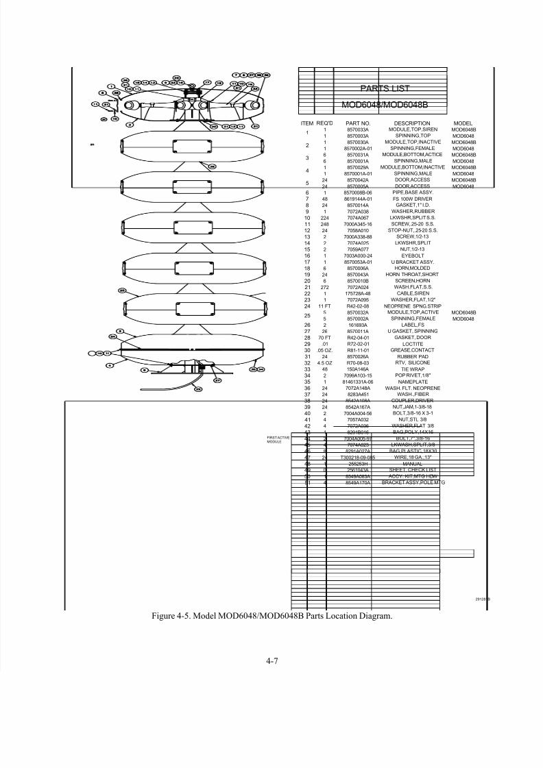
Figure 4-5. Model MOD6048/MOD6048B Parts Location Diagram.