modular adsorption dryers - rastgar air compressors...technology? compressed air purification must...
TRANSCRIPT

A-Series
Modular Adsorption Dryers Highly efficient air treatment
GB03
Innovative compressed air treatment

The A-Series modular compressed air dryers - a dedicated solution for every applicationBy combining the proven benefits of desiccant drying with modern design, CompAir provides an extremely compact and reliable system to totally dry and clean compressed air.
At the heart of any compressed air treatment solution is the dryer, it’s purpose, to remove water vapour, stop condensation, corrosion and in the case of adsorption dryers, inhibit the growth of micro-organisms.
The CompAir A-Series of heatless regenerative adsorption dryers have proven to be the ideal solution for many thousands of compressed air users worldwide in a wide variety of industries.
2
Totally dry and clean air
Why chose adsorption dryer technology?Compressed air purification must deliver uncompromising performance and reliability whilst providing the right balance of air quality with lowest cost of operation.
Heatless adsorption dryers, which are also known as PSA dryers, are the simplest type of adsorption dryer available and have long been the dryer of choice for many industries and applications. They are simple, reliable and cost effective and for small to medium flow systems, often the only viable technology available. Additionally, modular heatless dryers such as the A-Series provide an even more reliable, smaller, more compact and lightweight dryer which can be installed in both, the compressor room or at the point of use.

3
Clean, dry air improves production efficiency and reduces maintenance costs and downtime. Adsorption dryers provide the highest levels of dry compressed air.
““””
The benefits of heatless adsorption dryers: Robust and reliable industry proven design
Suitable for all industries and applications. Some adsorption dryer regeneration methods prevent their use in certain industries / applications.
Lower capital investment and reduced complexity compared to other adsorption dryer regeneration methods
Lower maintenance costs in comparison to other adsorption dryer regeneration methods
No heat, heaters or heat related issues
A-Series Product OverviewAX1N to AX7N Series Flowrates from 0.08 m³/min
How it worksAdorption dryers work on the principle of moisture always migrating to the driest medium possible. Therefore, water vapour is removed from compressed air by passing it over an adsorbent desiccant material.
As the air contacts the adsorbent material, water vapour transfers from the wet air to the dry desiccant, however, adsorbent materials have a fixed adsorption capacity and once this capacity is reached, they must be regenerated or replaced. Therefore, to provide a continuous supply of clean, dry compressed air, adsorbent dryers utilise two chambers of desiccant material and at any one time, whilst one chamber is on-line, drying the incoming compressed air, the other is either off-line, being regenerated or is re-pressurised, ready to come on-line. All adsorption dryers remove water in this manner.
The energy consumed by an adsorption dryer can be directly attributed to the method used to regenerate the adsorbent material. The CompAir A-Series dryers utilise the Heatless PSA method to regenerate the adsorbent material.
A68XS to A340XS Series Flowrates from 6.8 m³/min
AX10N to AX50N Series Flowrates from 0.86 m³/min
A068XLE – A340XLE Flowrates from 6.8 m3/min
NEW
Improving manufacturing efficiency
4
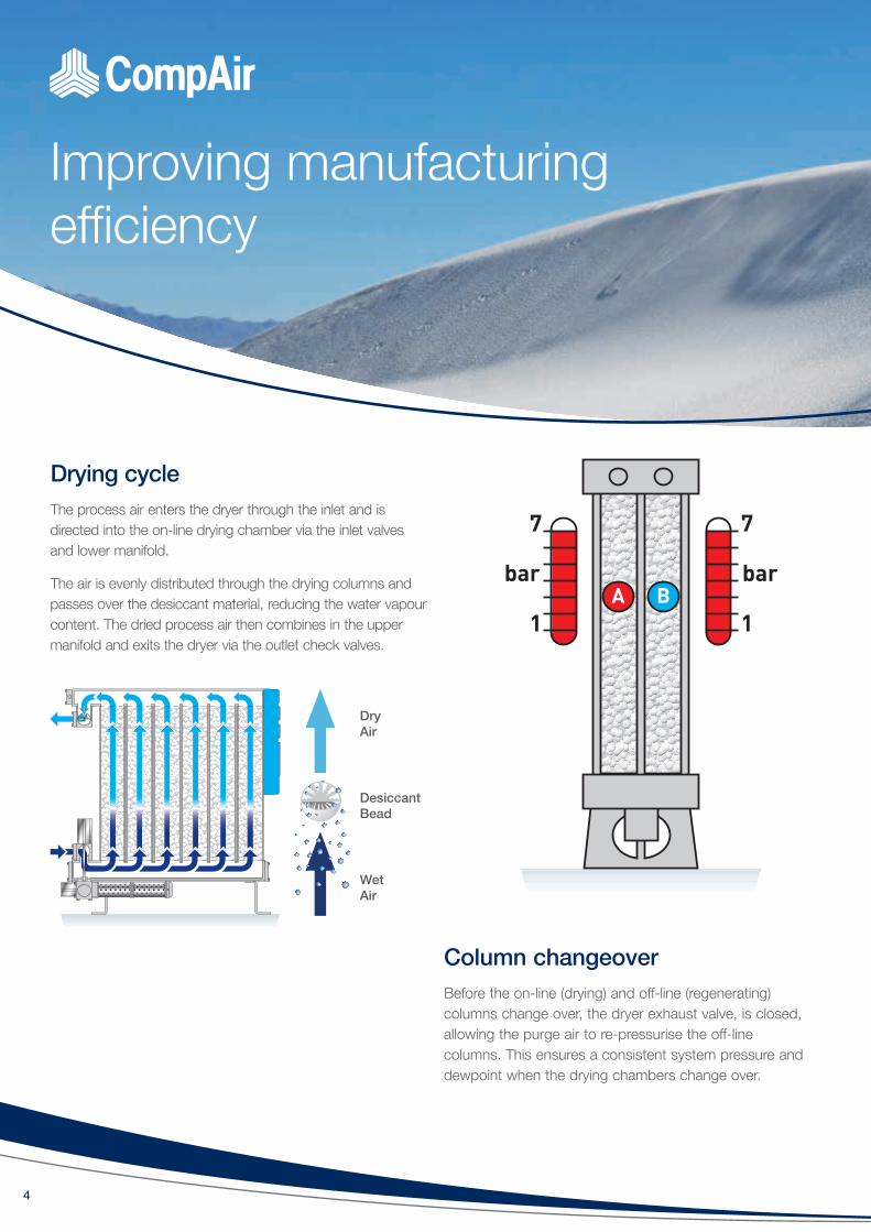
Column changeoverBefore the on-line (drying) and off-line (regenerating) columns change over, the dryer exhaust valve, is closed, allowing the purge air to re-pressurise the off-line columns. This ensures a consistent system pressure and dewpoint when the drying chambers change over.
Drying cycleThe process air enters the dryer through the inlet and is directed into the on-line drying chamber via the inlet valves and lower manifold.
The air is evenly distributed through the drying columns and passes over the desiccant material, reducing the water vapour content. The dried process air then combines in the upper manifold and exits the dryer via the outlet check valves.
Wet Air
DesiccantBead
Dry Air

5
Regeneration cycle (Heatless PSA)At the start of the regeneration cycle, the exhaust valve of the dryer is closed and the off-line chamber is at full line pressure. The air in the off-line chamber has dewpoint equal to the air leaving the dryer.
The exhaust valve is then opened and the dry air within the chamber expands rapidly as it leaves the dryer via the exhaust silencer, forcing water to be removed from the desiccant material.
Once the off-line chamber has de-pressurised, a continuous bleed of dried process air is directed into the off-line upper manifold. This air is known as purge air. With the exhaust valve open, the purge air expands from line pressure to atmospheric pressure and flows downwards through the columns, over the off-line desiccant material. As the purge air at line pressure contains a fixed amount of water vapour, allowing it to expand means the purge air becomes even drier, increasing its capacity to remove water from the saturated desiccant bed.
Four key features guarantee air qualityCompAir filtration
Adsorption dryers are designed for the removal of water vapour and not liquid water, water aerosols, oil, particulates or micro-organisms. Only by using CompAir pre and after filtration can the removal of theses contaminants be assured and air quality in accordance with all editions of ISO8573-1 be guaranteed.
Modular aluminium design
Aluminium extrusions are used throughout for drying chambers and distribution manifolds. This design allows the desiccant material to be retained within the drying chambers. ‘Snowstorm’ filling, prevents movement of the desiccant material during operation and also eliminates desiccant attrition and breakdown which could lead to a loss of pressure dewpoint.
Adsorption desiccant material
• Optimum adsorption and regeneration capacity > to ensure consistent dewpoint
• Low dusting > to prevent blockage of downstream filtration
• High crush strength > to prevent breakdown of the desiccant during operation
• High resistance to aggressive and oil-free condensate > for compatibility with all types of air compressor,
their lubricants and condensate
Wet Purge Air to Atmosphere
DesiccantBead
Dry Purge Air

6
Loose filled bed
Snowstorm filling
Inconsistent drying and desiccant attrition
The 'Snowstorm' filling technique ensures consistent dewpoint performance
Snowstorm filled bed
Consistent drying with no desiccant attrition
CompAir air treatment
The ‘Snowstorm” filling method
Utilised accross the CompAir modular dryers is the snowstorm filling technique used to charge the drying chambers with adsorbent desiccant material.
• Achieves maximum packing density for the desiccant material, fully utilising all of the available space envelope
• Prevents air channelling through the desiccant as experienced with twin tower designs. Due to channelling, twin tower designs require more desiccant to achieve an identical dewpoint increasing physical size, operational and maintenance costs
• Prevents desiccant attrition which can lead to dusting, blocked filters and loss of dewpoint
• Allows 100% of the available desiccant material to be used for drying, therefore reducing the amount of desiccant required and maintenance costs
• 100% of the desiccant is regenerated ensuring consistent dewpoint
• Provides a low, equal resistance to air flow allowing multiple drying chambers and multiple dryer banks to be used, a feature available with the A-Series from CompAir

7
System pressure 6 bar g. Max Temp 35°C. System flow 1700 m3/hr (1000 cfm). Average pressure 6.5 bar g. Average Temp 30°C.
Energy savings with dewpoint dependent switching (DDS) energy management system The energy required to regenerate the off-line desiccant bed in an adsorption dryer is constant, and based upon the assumption that the dryer is operating at its full capacity and the desiccant bed requiring regeneration has been fully saturated. In reality, a dryer is rarely operating at full capacity all of the time, for example during shift work and periods of low demand. Daily and seasonal fluctuations in ambient temperature and humidity also change the moisture loading placed upon the dryer.
Under such conditions, at the point in the drying cycle where the air flow is switched from one drying chamber to the other, there is the potential for drying capacity to remain in the desiccant material about to undergo regeneration. As the energy used to regenerate this partially saturated bed is based upon the assumption that the bed is fully saturated, more energy (purge air) is consumed than is actually necessary.
Time[Minutes]
DDS Drying / Regeneration Cycle
0 2.5 3Changeover time dictated by outlet
dewpoint
Changeover
0 2.5 3Changeover time dictated by outlet
dewpoint
Changeover
Side A Regeneration Re-pressurisation Energy Saving DryingSide B Drying Regeneration Re-pressurisation Energy Saving
Air Demand % Energy Saving %Energy Saving Environmental Saving
P/A kW P/A Kg CO2
100 33.00 95,040 50,371
90 40.00 115,200 61,056
80 47.00 135,360 71,741
70 53.00 152,640 80,899
60 60.00 172,800 91,584
50 66.00 190,080 100,742
DDS Operation - Energy Saving Cycle (Heatless Dryer example shown)
DDS Energy Saving (Heatless Dryer example shown)

Maximising efficiency
8
Elmo Rietschle rotary vane vacuum pump with IE3 motors according to UL 1004
XLE controller
Highest quality air at lowest costsThe CompAir AXLE compressed air dryer has been specifically designed to provide all of the benefits of the A-Series heatless adsorption dryer with the additional benefits of lower energy costs and lower environmental impact via its vacuum regeneration method, allowing around 17% more of the generated clean, dry compressed air to be used across the plant.
This is achieved by adding a vacuum assisted system.
Introducing AXLELow Energy Heatless Adsorption Dryers
The AXLE has been specifically designed to provide all of the benefits of a traditional A-Series heatless adsorption dryer with the additional benefits of increased compressed air available for plant use, lower energy costs and lower environmental impact.
Dryer Selection
Dryers should not be selected upon energy costs alone, but on delivered air quality, their suitability for the industry & application in which they are to operate, reliability and total cost of ownership.
DESIGNED FOR AIR QUALITY & ENERGY EFFICIENCY
REDUCED CO2
9
Complete clean dry air solution with guaranteed air quality• Includes Pre and Post Filtration• Delivered air quality in accordance with ISO08573-1• Suitable for all industrial applications
Low energy heatless technology• 17% more air available for use than a comparative
heatless dryer• On average, 60% lower energy consumption against
comparable heatless dryers and 39% lower energy consumption against heat regenerative dryers
• Energy Management System fitted as standard for additional savings
Ideally suited for food, beverage and pharmaceutical applications• Uses clean dry process air for regeneration (no
contamination of the adsorption bed)• Materials of Construction FDA Title 21 Compliant
and EC1935-2004 exempt
Lower total cost of ownership• Low running costs• Extended prevented maintenance periods and shorter
maintenance times• Lower maintenance costs compared to other types of
low energy dryers
Heatless fall back mode for extra security• Should a fault occur with the vacuum pump, the dryer
can be operated in full heatless mode to keep the plant operational
Modular design• Smaller, more compact and lightweight than traditional
Twin Tower dryers• Fully expandable as your system grows• Existing A-XS dryers can be upgraded to extend life of
existing capital equipment and lower capital expenditure
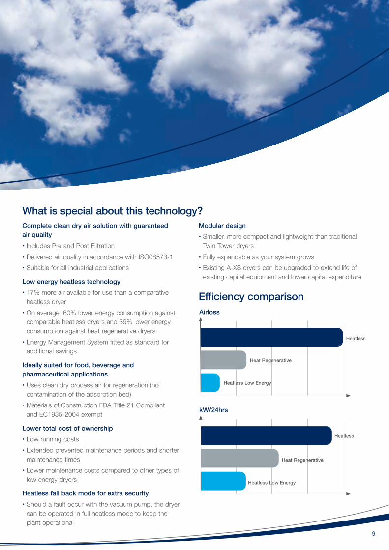
Airloss
kW/24hrs
Heatless Low Energy
Heatless Low Energy
Heat Regenerative
Heat Regenerative
Heatless
Heatless
What is special about this technology?
Efficiency comparison

10
Technical data
Weights and Dimensions
A Series AX1N - AX7N
Correction Factors
Technical Data
Model Pipe SizeInlet Flowrates
[m3/min] [m3/hr] [L/S] [cfm]
AX1N (PTC)* 0.08 5.1 1.4 3
AX2N (PTC)* 0.14 8.5 2.4 5
AX3N (PTC)* 0.28 17 4.7 10
AX4N (PTC)* 0.43 26 7.2 15
AX7N (PTC)** 0.68 41 11.4 24
Dryer Performance
Dryer Models
*Dewpoint [Standard] ISO8573-1:2010Classification [Standard] *Dewpoint [Option 1] ISO8573-1:2010
Classification [Option 1][°C] [°F] [°C] [°F]
AX_N -40 -40 Class 2 -70 -100 Class 1
Temperature Correction Factor CFT
Maximum Inlet
Temperature
[°C] 25 30 35 40 45 50[°F] 77 86 95 104 113 122CFT 1.00 1.00 1.04 1.04 1.14 1.37
Pressure Correction Factor CFP
Minimum Inlet
Pressure
[bar g] 4 5 6 7 8 9 10 11 12 13 14 16[psi g] 58 73 87 102 116 131 145 160 174 189 203 232CFP 1.60 1.33 1.14 1.00 0.88 0.8 0.72 0.67 0.61 0.57 0.53 0.47
Dewpoint Correction Factor CFD Standard Option 1
Required Dewpoint
PDP °C -40 -70PDP °F -40 -100
CFD 1.00 1.43
Dryer Models
Min OperatingPressure
Max OperatingPressure
Min InletTemperature
Max InletTemperature
Max AmbientTemperature
[bar g] [psi g] [bar g] [psi g] [°C] [°F] [°C] [°F] [°C] [°F]
AX_N 4 58 16 232 1.5 35 50 122 50 122
Dryer Models
Electrical Supply [Standard] Tolerance ± 10%
ThreadConnection
Noise Level[Average]
dB[A]AX_N 100 - 240 VAC / 50 or 60 Hz BSPP or NPT <75
Electronic Controller Options
FunctionPower OnIndication
Service Interval Indication
AX_N • •
Stated flows are for operation at 7 bar g (100 psi g) with reference to 20°C, 1 bar a, 0% relative water vapour pressure. For flows at other pressures, apply the correction factors shown.
Product Selection
Model Filter Pipe Size BSPT or NPT
Inlet General Purpose Pre-filter
Outlet Dust Filter
AX1N
³⁄8"CF0006G3/8'B
&CF0006G3/8'C
Built into dryerAX2NAX3NAX4NAX7N
Model Pipe Size
DimensionsWeight
Height [H] Width [W] Depth [D][mm] [ins] [mm] [ins] [mm] [ins] [Kg]
AX1N
PTC
439 17.3
263 10.3220 8.7
9AX2N 439 17.3 9AX3N 649 25.6 14AX4N 893 35.2
280 11.019
AX7N 1193 47.0 26
Recommended Filtration
* 8mm push to connect fittings in inlet and outlet **12mm push to connect fittings in inlet and outlet

11
AX10N to AX50NProduct Selection
Dryer Performance
Dryer ModelsDewpoint [Standard] ISO8573-1:2010
Classification [Standard]
Dewpoint [Option 1] ISO8573-1:2010 Classification [Option 1][°C] [°F] [°C] [°F]
AX10N - AX50N -40 -40 Class 2 -70 -100 Class 1
Technical Data
Dryer ModelsMin Operating
PressureMax Operating
PressureMin Operating Temperature
Max Operating Temperature
Max Ambient Temperature
Electrical Supply
[Standard]
Thread Connection
Noise Level
[bar g] [psi g] [bar g] [psi g] [°C] [°F] [°C] [°F] [°C] [°F] [dB(A)]
AX10NS - AX50NS 4 58 16 232 1.5 35 50 122 50 122 110-240 VAC 50/60 Hz
BSPP or NPT <85
Controller Options
Function
Power On Indication Fault Indication Service Interval
Indication
Configurable Alarm
Settings
Remote Volt Free Alarm contacts
DDS Energy Management
System
Dew Point Display
AX10N - AX50N (Electronic Control] •
••
AX10NS - AX50NS • • • •
Controller Options
Stated flows are for operation at 7 bar g (100 psi g) with reference to 20°C, 1 bar a, 0% relative water vapour pressure. For flows at other pressures, apply the correction factors shown.
Model Pipe SizeInlet Flowrates
[m3/min] [m3/hr] [L/S] [cfm]AX10N
1"
0.96 58 16 34AX12N 1.17 70 19 41AX15N 1.50 90 25 53AX19N 1.87 112 31 66AX25N 2.50 150 42 88AX30N 3.00 180 50 106AX38N 3.73 224 62 132AX50N 5.02 301 84 177
Correction FactorsTemperature Correction Factor CFT
Maximum Inlet Temperature
[°C] 25 30 35 40 45 50[°F] 77 86 95 104 113 122CFT 1.00 1.00 1.04 1.04 1.14 1.37
Pressure Correction Factor CFP
Minimum Inlet Pressure
[bar g] 4 5 6 7 8 9 10 11 12 13 14 16
[psi g] 58 73 87 100 116 131 145 160 174 189 203 232
CFP 1.60 1.33 1.14 1.00 0.88 0.80 0.72 0.67 0.61 0.57 0.53 0.47
Dewpoint Correction Factor CFD Standard Option 1
Required Dewpoint
PDP °C -40 -70PDP °F -40 -100
CFD 1.00 1.43
Outlet dust filter built into dryer.
12
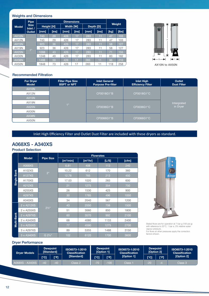
Weights and Dimensions
Model
Pipe Size
Inlet / Outlet
DimensionsWeight
Height [H] Width [W] Depth [D]
[mm] [ins] [mm] [ins] [mm] [ins] [kg] [lbs]AX10N
1"
743 29 426 17 283 11 47 103AX12N 743 29 426 17 283 11 47 103AX15N 923 36 426 17 283 11 58 127AX19N 923 36 426 17 283 11 58 127AX25N 1098 43 426 17 283 11 71 155AX30N 1248 49 426 17 283 11 83 182AX38N 1498 59 426 17 283 11 96 210AX50N 1848 73 426 17 283 11 118 258
For Dryer Model
Filter Pipe Size BSPT or NPT
Inlet General Purpose Pre-filter
Inlet High Efficiency Filter
Outlet Dust Filter
AX10N
1"
CF0018G1"B CF0018G1"C
Intergrated in Dryer
AX12NAX15NAX19N
CF0036G1"B CF0036G1"CAX25NAX30NAX38N
CF0066G1"B CF0066G1"CAX50N
Recommended Filtration
Inlet High Efficiency Filter and Outlet Dust Filter are included with these dryers as standard.
Sing
le B
ank
Model Pipe SizeFlowrates
[m3/min] [m3/hr] [L/S] [cfm]A068XS
2"
6.81 408 113 240A102XS 10.22 612 170 360A127XS 12.78 765 213 450A170XS 17.03 1020 283 600A212XS
2½"
21 1275 354 750A255XS 26 1530 425 900A297XS 30 1785 496 1050A340XS 34 2040 567 1200
Mul
ti-Ba
nk
2 x A212XS 43 2550 708 15002 x A255XS 51 3060 850 18002 x A297XS 60 3570 992 21002 x A340XS 68 4080 1133 24003 x A255XS 77 4590 1275 27003 x A297XS 89 5355 1488 31503 x A340XS G 2½" 102 6120 1700 3600
Stated flows are for operation at 7 bar g (100 psi g) with reference to 20°C, 1 bar a, 0% relative water vapour pressure. For flows at other pressures apply the correction factors shown.
A068XS - A340XSProduct Selection
Dryer Performance
Dryer ModelsDewpoint [Standard]
ISO8573-1:2010 Classification
[Standard]
Dewpoint [Option 1]
ISO8573-1:2010 Classification
[Option 1]
Dewpoint [Option 2]
ISO8573-1:2010 Classification
[Option 2][°C] [°F] [°C] [°F] [°C] [°F]
A068XS - A340XS -40 -40 Class 2 -70 -100 Class 1 -20 -4 Class 3
AX10N to AX50N
B C
A

13
Technical Data
Dryer Models
Min Operating Pressure
Max Operating Pressure
Min Operating
Temp
Max Operating
Temp
Max Ambient
TempElectrical
supply [Standard]
Electrical supply
[Optional]
Thread Connections
Noise Level
[bar g] [psi g] [bar g] [psi g] [°C] [°F] [°C] [°F] [°C] [°F] [dB(A)]AX_S
4 58 13 190 5 41 50 122 55 131 85 - 265 V 1ph 50/60Hz N/A BSPP
or NPT <75AX _E
Weights and Dimensions
Model Pipe Size
DimensionsWeight
Height [H] Width [W] Depth [D]
[mm] [ins] [mm] [ins] [mm] [ins] [kg] [lbs]
A068XS
2"1647 64.8
687 27.0
550 21.7
235 518A102XS
856 33.7316 696
A127XS
1892 74.5
355 782A170XS 1025 40.3 450 992A212XS
2½"
1194 47.0 543 1197A255XS 1363 53.6 637 1404A297XS 1532 60.3 731 1611A340XS 1701 67.0 825 1818
Controller Options
Controller Options
Function
Power on Indication
Fault Indication
Display Fault Condition
Values
Service Interval
Indication
Service Countdown
Timers
Configurable Alarm
Settings
Remote Volt Free Alarm Contacts
Filter Service Timer
DDS Energy Management
SystemAX_S
• • • •AX_SDS •AX_E • • • •
Correction FactorsTemperature Correction Factor CFT
Maximum Inlet Temperature
[°C] 25 30 35 40 45 50[°F] 77 86 95 104 113 122CFT 1.00 1.00 1.00 1.04 1.14 1.37
Pressure Correction Factor CFP
Minimum Inlet Pressure
[bar g] 4 5 6 7 8 9 10 11 12 13[psi g] 58 73 87 100 116 131 145 160 174 189CFP 1.60 1.33 1.14 1.00 0.89 0.80 0.73 0.67 0.62 0.57
Dewpoint Correction Factor CFD Option 2 Standard Option 1
Required Dewpoint
PDP °C -20 -40 -70
PDP °F -4 -40 -100
CFD 0.91 1.00 1.43
* ATEX compliant option available. For hazardous environments, a fully pneumatic ATEX compliant version of AX Series is available. ATEX Directive 94/9/EC, Group II, Category 2GD, T6.
D W
H
A068XS - A340XS
Recommended Filtration
For Dryer Model Filter Pipe Size BSPT or NPT
Inlet General Purpose Pre-filter Inlet High Efficiency Filter Outlet Dust Filter
A068XS
2"CF0132G 2"G CF0132G 2"H CF0132G 2"G
A102XSA127XS
CF0198G 2"G CF0198G 2"H CF0198G 2"GA170XSA212XS
2½"
CF0258G2 ½"G CF0258G2 ½"H CF0258G2 ½"GA255XS
CF0372G2 ½"G CF0372G2 ½"H CF0372G2 ½"GA297XSA340XS
Inlet High Efficiency Filter and Outlet Dust Filter are included with these dryers as standard.

14
Technical dataA068XLE – A340XLE
Dewpoint Correction Factor CFD Option 2 Standard Option 1
Required Dewpoint
PDP °C -20 -40 -70PDP °F -4 -40 -100
CFD 0.91 1.00 1.43
Dryer Performance
Correction Factors
Technical Data
Sing
le B
ank
Model Pipe SizeInlet Flowrates
[m3/min] [m3/hr] [L/S] [cfm]
A068XLE 2" 6.81 408 113 240
A102XLE 2" 10.22 612 170 360
A127XLE 2" 12.78 765 213 450
A170XLE 2" 17.03 1020 283 600
A212XLE 2½" 21 1275 354 750
A255XLE 2½" 26 1530 425 900
A297XLE 2½" 30 1785 496 1050
A340XLE 2½" 34 2040 567 1200
Temperature Correction Factor CFT
Maximum Inlet Temperature
[°C] 25 30 35 40 45 50[°F] 77 86 95 104 113 122CFT 1.00 1.00 1.00 1.04 1.14 1.37
Pressure Correction Factor CFP
Minimum Inlet
Pressure
[bar g] 5 6 7 8 9 10 11 12 13[psi g] 73 87 100 116 131 145 160 174 189CFP 1.33 1.14 1.00 0.89 0.80 0.73 0.67 0.62 0.57
Product Selection
Stated flows are for operation at 7 bar g (100 psi g) with reference to 20 °C, 1 bar a, 0 % relative water vapour pressure. For flows at other pressures apply the correction factors shown.
Dryer ModelsDewpoint [Standard]
ISO8573-1:2010 Classification
[Standard]
Dewpoint [Option 1]
ISO8573-1:2010 Classification
[Option 1]
Dewpoint [Option 2]
ISO8573-1:2010 Classification
[Option 2][°C] [°F] [°C] [°F] [°C] [°F]
AXLE -40 -40 Class 2 -70 -100 Class 1 -20 -4 Class 3* ISO8573-1 Classifications when used with included CompAir CF range pre / post filtration.
Dryer Models
Min Operating Pressure
Max Operating Pressure
Min Operating
Temp
Max Operating
Temp
Max Ambient
TempElectrical supply
[Standard]
Electrical supply
[Optional]
Thread Connections
Noise Level
[bar g] [psi g] [bar g] [psi g] [°C] [°F] [°C] [°F] [°C] [°F] [dB(A)]
AXLE 5 58 13 190 5 41 50 122 55 131 230V - 460V 3PH 50Hz 230V - 460V 3PH 60Hz N/A BSPP
or NPT <75
Model A102CXLE A103CXLE A103XLE A104XLE A105XLE A106XLE A107XLE A108XLE
Vacuum Pump kW
50Hz 3 3 4 5.5 5.5 8 9.5 9.560Hz 4.8 4.8 6.5 9 9 13 15.5 15.5
For correct operation, compressed air dryers must be sized for the minimum inlet pressure, maximum inlet temperature and maximum flow rate at the point of installation. To select a dryer, first calculate the MDC (Minimum Drying Capacity) using the formula below then select a dryer from the flow rate table above, with a flow rate equal to or greater than the MDC.Minimum Drying Capacity = System Flow x CFT x CFP x CFD

15
Included Filtration
For Dryer Model Filter Pipe Size BSPT or NPT Inlet General Purpose Pre-filter Inlet High Efficiency Filter Outlet Dust Filter
A068XLE
2"
CF0132G2"B CF0132G2"C CF0132G2”BA102XLE
A127XLECF0198G2"B CF0198G2"C CF0198G2"B
A170XLE
A212XLE
2½"
CF0198G2"B CF0258G21/2"C CF0258G21/2"BA255XLE
CF0372G21/2"B CF0372G21/2"C CF0372G21/2"BA297XLE
A340XLE
Weights and Dimensions
Model Pipe Size
Dryer DimensionsWeight
Height [H] Width [W] Depth [D]
[mm] [ins] [mm] [ins] [mm] [ins] [kg] [lbs]A068XLE
2"
1647 64.8793.5 31.5
550 21.7
265 583A102XLE
962.5 37.9346 761
A127XLE
1892 74.5
385 847A170XLE 1131.5 44.6 480 1056A212XLE
2½"
1300.5 51.2 573 1261A255XLE 1469.5 57.9 667 1467A297XLE 1641.5 64.6 761 1674A340XLE 1807.5 71.2 855 1881
Model
Vacuum Pump DimensionsWeight
Height [H] Width [W] Depth [D]
[mm] [ins] [mm] [ins] [mm] [ins] [kg] [lbs]A068XLE
400 15.75 933 36.73 523 20.59
89 196A102XLE
A127XLE 194 428A170XLE
184 406A212XLE
A255XLE
1304 51.34 1100 43.31 560 22.05
420 926A297XLE
390 860A340XLE
Part Numbers
Dryer Part Numbers Vacuum Pump Part Numbers 50Hz
Vacuum Pump Part Numbers 60Hz
Dryer Upgrade Kits Part Numbers
A068XLE A068XLEP-50 A068XLEP-60 A068XLEK
A102XLE A102XLEP-50 A102XLEP-60 A102XLEK
A127XLE A127XLEP-50 A127XLEP-60 A127XLEK
A170XLE A170XLEP-50 A170XLEP-60 A170XLEK
A212XLE A212XLEP-50 A212XLEP-60 A212XLEK
A255XLE A255XLEP-50 A255XLEP-60 A255XLEK
A297XLE A297XLEP-50 A297XLEP-60 A297XLEK
A340XLE A340XLEP-50 A340XLEP-60 A340XLEK
VP (H)
A068XLE – A212XLESINGLE VACUUM PUMP
A255xle – A340XLEDUPLEX VACUUM PUMP
D D
H
W
H
DRYER VACUUM PUMP
W

Global experience ‒truly local service
CompAir compressed air product range
With over 200 years of engineering excellence, the CompAir brand offers an extensive range of highly reliable, energy efficient compressors and accessories to suit all applications.
An extensive network of dedicated CompAir sales companies and distributors across all continents provide global expertise with a truly local service, ensuring our advanced technology is backed up with the right support.
As part of the worldwide Gardner Denver operation, CompAir has consistently been at the forefront of compressed air systems development, culminating in some of the most energy efficient and low environmental impact compressors on the market today, helping customers achieve or surpass their sustainability targets.
Advanced Compressor TechnologyLubricated• Rotary Screw > Fixed and Regulated Speed• Piston• Portable
Oil-Free• Water Injected Screw > Fixed and Regulated Speed• Two Stage Screw > Fixed and Regulated Speed• Piston• High Speed Centrifugal - Quantima®
• Rotary Scroll
Complete Air Treatment Range• Filter• Refrigerant and Desiccant Dryer• Condensate Management• Heat of Compression Dryer• Nitrogen Generator
Modern Control Systems• CompAir DELCOS Controllers• SmartAir Master Sequencer• iConn - Smart Flow Management
Value Added Services• Professional Air Audit• Performance Reporting• Leak Detection
Leading Customer Support• Custom Engineered Solutions• Local Service Centres• Genuine CompAir Parts
and Lubricants
www.compair.com [email protected]
CompAir policy is one of continuous improvement and we therefore reserve the right to alter specifications and prices without prior notice. All products are sold subject to the Company’s conditions of sale.
576G
B 12
/19