modulair pump skids 1900 - colmac coil · page 3 selection procedure: modulair pump skid...
TRANSCRIPT

Bulletin 1900 Modulair™ by Colmac Coil
MODULAIR™ BY COLMAC COIL PUMP SKIDS
4 Models Capacities to 2,300 gpm
“The Heat Transfer Experts”

Page 2
STANDARD FEATURES:Modulair Pump Skids are designed for closed loop cooling of water, ethylene glycol / water and propylene glycol / watersolutions with air cooled fluid coolers for many power generation cooling applications.
Modulair Pump Skids are available in a series of four pre-engineered standard modules with a range of flows from 200gpm to 2300 gpm. The pump skid performance charts are included in the data sheets in this bulletin to show the stan-dard pump head available with the corresponding flow for each skid size for 50 and 60 HZ operation. The pump headcan be increased up to the maximum head shown for 60 HZ operation by selecting a larger pump impeller and using theoptional larger pump motor size shown on the charts. Optional larger pumps and motors are also available for skid sizesMOD 150 to MOD 250 to provide up to 280 feet head at 60 HZ and 195 feet head at 50 HZ operation. The optimum sizeof pump skid can easily be selected for most cooling applications using the information shown in these data sheets. Thefooting dimensions and pipe connection sizes and locations are provided to allow the preliminary installation layoutrequired for any application.
• Four basic pump skid sizes for flows from 200 gpm to 2300 gpm.• Two 100% full rated pumps and motors rated for continuous outdoor duty.• Bladder type expansion tank prevents air contact with the glycol/water solution.• Design pressure 125 psig @ 200 F at inlet and 150 psig at outlet with 150# ANSI RF flanges.• Piping fabricated to ASME B31.1.• Dual outlet connections to simplify connections to two cooler modules.• Heavy-duty foot mounted TEFC motors high efficiency 1.15 SF with Class F insulation.• Motors are 1450 RPM for 50 HZ and 1780 RPM for 60 HZ operation.• Motors and switches are factory wired to a weatherproof NEMA 4 electrical enclosure located at the expansion tank
end of the skid to provide single point field wiring.• Pressure switch on outlet for signal to pump changeover.• Pressure switch at inlet for low liquid level alarm.• Structural steel base and piping painted primer plus 2 coats enamel finish.• Provision in base for grounding connections.• Built in lifting connections to simplify lifting and installation.
PUMP FEATURES:• Heavy duty ANSI standard end-suction centrifugal design flanged pump with ductile iron construction.• Open impeller with external adjustment and balanced to ISO Figure 2 Level G6.3.• Extra heavy duty shaft to ANSI B73.1M and oil lubricated bearings minimum life (L10) of two years.• Industry Standard Mechanical Shaft Seal.• Flexible type spacer shaft coupling.• Fully enclosed, telescoping, OSHA compliant steel coupling guard.
OPTIONS:• Larger motors for 60 HZ operation to provide pump head above the standard head shown.• Gravity type overhead expansion tank instead of the bladder tank.• Extra capacity bladder tanks for very large systems.• Larger pumps and motors and skid bases for MOD 150 to MOD 250 to provide pump head above the maximum
head shown for up to 280 feet head for 60 HZ and 195 feet head for 50 HZ.
NOMENCLATURE:MOD 150 - 800 - 100 - 40 - D
Motor voltage: B – 208-230/60/3D – 460/60/3E – 575/60/3F – 380/60/3H – 200/60/3I – 400/50/3
Motor horsepower
Modulair
Pump Skid Size
Flow, gpm
Head, feet
Page 3
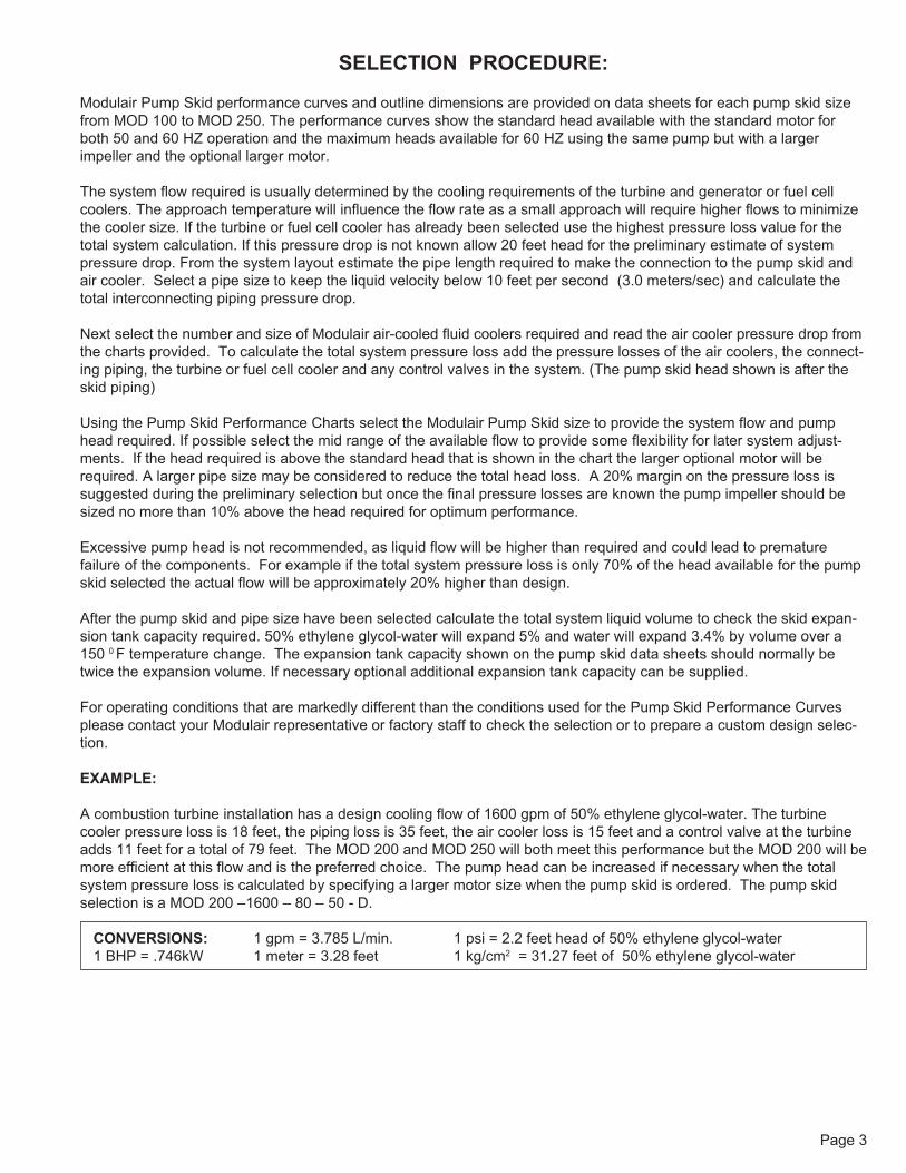
SELECTION PROCEDURE:
Modulair Pump Skid performance curves and outline dimensions are provided on data sheets for each pump skid sizefrom MOD 100 to MOD 250. The performance curves show the standard head available with the standard motor forboth 50 and 60 HZ operation and the maximum heads available for 60 HZ using the same pump but with a largerimpeller and the optional larger motor.
The system flow required is usually determined by the cooling requirements of the turbine and generator or fuel cellcoolers. The approach temperature will influence the flow rate as a small approach will require higher flows to minimizethe cooler size. If the turbine or fuel cell cooler has already been selected use the highest pressure loss value for thetotal system calculation. If this pressure drop is not known allow 20 feet head for the preliminary estimate of systempressure drop. From the system layout estimate the pipe length required to make the connection to the pump skid andair cooler. Select a pipe size to keep the liquid velocity below 10 feet per second (3.0 meters/sec) and calculate thetotal interconnecting piping pressure drop.
Next select the number and size of Modulair air-cooled fluid coolers required and read the air cooler pressure drop fromthe charts provided. To calculate the total system pressure loss add the pressure losses of the air coolers, the connect-ing piping, the turbine or fuel cell cooler and any control valves in the system. (The pump skid head shown is after theskid piping)
Using the Pump Skid Performance Charts select the Modulair Pump Skid size to provide the system flow and pumphead required. If possible select the mid range of the available flow to provide some flexibility for later system adjust-ments. If the head required is above the standard head that is shown in the chart the larger optional motor will berequired. A larger pipe size may be considered to reduce the total head loss. A 20% margin on the pressure loss issuggested during the preliminary selection but once the final pressure losses are known the pump impeller should besized no more than 10% above the head required for optimum performance.
Excessive pump head is not recommended, as liquid flow will be higher than required and could lead to prematurefailure of the components. For example if the total system pressure loss is only 70% of the head available for the pumpskid selected the actual flow will be approximately 20% higher than design.
After the pump skid and pipe size have been selected calculate the total system liquid volume to check the skid expan-sion tank capacity required. 50% ethylene glycol-water will expand 5% and water will expand 3.4% by volume over a150 0 F temperature change. The expansion tank capacity shown on the pump skid data sheets should normally betwice the expansion volume. If necessary optional additional expansion tank capacity can be supplied.
For operating conditions that are markedly different than the conditions used for the Pump Skid Performance Curvesplease contact your Modulair representative or factory staff to check the selection or to prepare a custom design selec-tion.
EXAMPLE:
A combustion turbine installation has a design cooling flow of 1600 gpm of 50% ethylene glycol-water. The turbinecooler pressure loss is 18 feet, the piping loss is 35 feet, the air cooler loss is 15 feet and a control valve at the turbineadds 11 feet for a total of 79 feet. The MOD 200 and MOD 250 will both meet this performance but the MOD 200 will bemore efficient at this flow and is the preferred choice. The pump head can be increased if necessary when the totalsystem pressure loss is calculated by specifying a larger motor size when the pump skid is ordered. The pump skidselection is a MOD 200 –1600 – 80 – 50 - D.
CONVERSIONS: 1 gpm = 3.785 L/min. 1 psi = 2.2 feet head of 50% ethylene glycol-water1 BHP = .746kW 1 meter = 3.28 feet 1 kg/cm2 = 31.27 feet of 50% ethylene glycol-water

Page 4
MOD 100 PUMP SKID PERFORMANCE CURVE
IN INCHESALL DIMENSIONS
(59)
1.00"DIA. - 8 MOUNTING HOLES
31.2549.50
1 1/4"NPTDRAIN &FILL
OUTLETFLANGE(2)
OUTLETFLANGE(1)
INLETFLANGE
Ø24.00
(121)
7.25
7.25
45.50
4.00
4.00
4.00
60.00 52.00
4.00
116
27.5
10.00
6.00
44.95
44.20
7.00
16.00
24.00
28.00
PAINT: ENAMEL FINISH
100 FEET HEAD
DESIGN PRESSURE OUT: 150 PSIG
IN/OUT CONNECTION : 4"-150#-RF
DESIGN PRESSURE IN : 125 PSIG
(with 30 HP motor)
Std. Motor BHP.
Max. BHP.
Std. Head
Max. Head
FLOW GPM 50% glycol-water
BHP
HEA
D fe
et
30
20
10
0450400350300250200
200
180
160
140
120
100
80
60
40
20
0
DRY WEIGHT: 2275 LBS.
FLOODED WT.: 2685 LBS.
PRESSURIZED, BLADDER TYPE
EXPANSION TANK, VOLUME 53 GAL.
NOMINAL GPM: 350 AT
STD. PUMP MOTORS : (2) 20 HP
FIGURE 1MODULAIR PUMP SKID-MOD 100
FIGURE 2
ALL DIMENSIONS IN INCHES
Page 5
BHP
60
40
Max. Head
Max. BHP.
Std. Head 50 Hz
Std. Head 60 Hz
200
180
160
140
120
100
80
60
40
(with 60 HP motor)
011001000800600 700 900500
0400
20 20Std. Motor BHP.
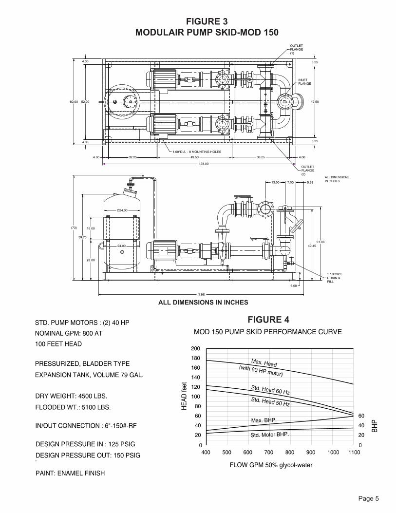
MOD 150 PUMP SKID PERFORMANCE CURVE
(136)
(73)
38.2549.50
5.25
4.00
5.25
13.00
49.50
6.00
7.00 5.38
49.4551.06
4.00
4.00
16.00
24.00
Ø24.00
60.00
28.00
59.75
128.00
52.00
4.00
32.25
IN INCHESALL DIMENSIONS
1.00"DIA. - 8 MOUNTING HOLES
1 1/4"NPTDRAIN &FILL
OUTLETFLANGE(2)
OUTLETFLANGE(1)
INLETFLANGE
PAINT: ENAMEL FINISH
100 FEET HEAD
DESIGN PRESSURE OUT: 150 PSIG
IN/OUT CONNECTION : 6"-150#-RF
DESIGN PRESSURE IN : 125 PSIG
FLOW GPM 50% glycol-water
HEA
D fe
et
DRY WEIGHT: 4500 LBS.
FLOODED WT.: 5100 LBS.
PRESSURIZED, BLADDER TYPE
EXPANSION TANK, VOLUME 79 GAL.
NOMINAL GPM: 800 AT
STD. PUMP MOTORS : (2) 40 HP
FIGURE 3MODULAIR PUMP SKID-MOD 150
FIGURE 4
ALL DIMENSIONS IN INCHES

Page 6
80
Max. Head
1500 17001600
Std. Motor BHP.
Max. BHP.
Std. Head
(with 75 HP motor)
MOD 200 PUMP SKID PERFORMANCE CURVE
BHP
HEA
D fe
et
60
40
20
014001300120011001000900
200
180
160
140
120
100
80
60
40
20
0
58.38
(101)
61.504.00 31.50
76.00
148.00
47.00
68.00
4.00
4.00
17.50
5.00Ø24.00
16.00
24.00
28.00
87.75
6.00
59.50
4.00
7.50
61.00
7.50
9.88
(160)
IN INCHESALL DIMENSIONS
1.00"DIA. - 8 MOUNTING HOLES
1 1/2"NPTDRAIN &FILL
OUTLETFLANGE(2)
OUTLETFLANGE(1)
INLETFLANGE
PAINT: ENAMEL FINISH
100 FEET HEAD
DESIGN PRESSURE OUT: 150 PSIG
IN/OUT CONNECTION : 8"-150#-RF
DESIGN PRESSURE IN : 125 PSIG
FLOW GPM 50% glycol-water
DRY WEIGHT: 4970 LBS.
FLOODED WT.: 6080 LBS.
PRESSURIZED, BLADDER TYPE
EXPANSION TANK, VOL. 132 GAL.
NOMINAL GPM: 1200 AT
STD. PUMP MOTORS : (2) 50 HP
FIGURE 5MODULAIR PUMP SKID-MOD 200
ALL DIMENSIONS IN INCHES
80
Max. Head
1500 17001600
Std. Motor BHP.
Max. BHP.
Std. Head
(with 75 HP motor)
MOD 200 PUMP SKID PERFORMANCE CURVE
BHP
HEA
D fe
et
60
40
20
014001300120011001000900
200
180
160
140
120
100
80
60
40
20
0
FLOW GPM 50% glycol-water
FIGURE 6
Page 7
120
100
80
Max. Head
2100 23002200
Std. Motor BHP.
Max. BHP.
Std. Head
(with 125 HP motor)
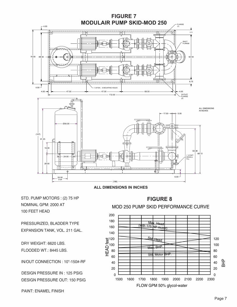
MOD 250 PUMP SKID PERFORMANCE CURVE
BHP
HEA
D fe
et
60
40
20
0200019001800170016001500
200
180
160
140
120
100
80
60
40
20
0
INLETFLANGE
(107)
4.00
1 1/2"NPTDRAIN &FILL
6.00
68.13
1.00"DIA. - 8 MOUNTING HOLES
47.00
4.00
4.00
76.00
47.50
Ø30.00
16.00
24.00
20.00TYP
91.25
28.00
69.50
172.00
68.00
4.00
62.50
6.75
6.75
63.38
17.00 5.00
(186)
IN INCHESALL DIMENSIONS
OUTLETFLANGE(2)
FLANGE(1)
PAINT: ENAMEL FINISH
100 FEET HEAD
DESIGN PRESSURE OUT: 150 PSIG
IN/OUT CONNECTION : 10"-150#-RF
DESIGN PRESSURE IN : 125 PSIG
FLOW GPM 50% glycol-water
DRY WEIGHT: 6620 LBS.
FLOODED WT.: 8445 LBS.
PRESSURIZED, BLADDER TYPE
EXPANSION TANK, VOL. 211 GAL.
NOMINAL GPM: 2000 AT
STD. PUMP MOTORS : (2) 75 HP
FIGURE 7MODULAIR PUMP SKID-MOD 250
FIGURE 8
ALL DIMENSIONS IN INCHES

Other Quality Products From Colmac Coil
Midwest US ManufacturingColmac Coil Midwest350 Baltimore Dr. | Paxton, IL 60957 | USA
North American HeadquartersColmac Coil Manufacturing, Inc.370 N. Lincoln St. | P.O. Box 571Colville, WA 99114 | USA+1.509.684.2595 | +1.800.845.6778
CE(PED) Certification, ASME Sec. VIII, Canadian Registration Number, UL508, Canadian Standards Association
CRN CSA
©2012 Colmac Coil "The Heat Transfer Experts"
Heat Pipes for Heat Recovery
Custom Evaporators & Baudelot Coolers
Heating and Cooling Coils Air Cooled CondensersDry Coolers for Glycol or Gas Cooling
Visit www.colmaccoil.com for more information and resources:
Product Information
Product Literature
Sales Rep Locator
Sales Rep e-Library
Product Videos