modis lut information guide - nasa€¦ · mcst l1b. l1b v6.1.14 (terra) /v6.1.17 (aqua) luts ....
TRANSCRIPT

SGS F C S B R
MCST Internal Memorandum # M1056
REV. B Prepared by
Members of the MODIS Characterization Support Team For
NASA/Goddard Space Flight Center Greenbelt, MD 20771
July 30, 2012
MODIS LUT INFORMATION GUIDE
For Level 1B Version 6.1.14 (Terra) and Version 6.1.17 (Aqua)


MCST L1B L1B V6.1.14 (TERRA) /V6.1.17 (AQUA) LUTs Page iii Software Support Team July 30, 2012
TABLE OF CONTENTS
1 INTRODUCTION AND CHANGES FROM THE PREVIOUS RELEASE ........................... 1 2 GENERAL INFORMATION, CONVENTIONS, AND VERSIONING STRATEGY ........... 4
2.1 LUT HDF FILES, LUT TYPE AND TIME-DEPENDENT LUTS ...................................................... 4 2.2 CONVENTIONS IMPLEMENTED IN THE LEVEL 1B HDF LUTS ..................................................... 5
2.2.1 Band Groupings and Ordering ......................................................................................... 5 2.2.2 Intrinsic Ordering of Detectors Within a Band ................................................................ 5 2.2.3 Intrinsic Order in a Multidimensional Array .................................................................... 5
2.3 STRATEGY FOR VERSIONING THE LEVEL 1B CODE AND LUTS .................................................. 6
3 REFLECTIVE LUTS .................................................................................................................... 7 3.1 SUMMARY OF REFLECTIVE LUTS AND THEIR DIMENSIONS ........................................................ 7 3.2 REFLECTIVE LUT LISTING ......................................................................................................... 9
3.2.1 Serial Number of Reflective LUT ....................................................................................... 9 3.2.2 PGE Version ...................................................................................................................... 9 3.2.3 MCST Version .................................................................................................................. 10 3.2.4 K_inst ............................................................................................................................... 10 3.2.5 K_FPA ............................................................................................................................. 11 3.2.6 m0 ..................................................................................................................................... 12 3.2.7 m1 ..................................................................................................................................... 12 3.2.8 RVS_RSB .......................................................................................................................... 13 3.2.9 u1 ..................................................................................................................................... 13 3.2.10 u2 ................................................................................................................................... 14 3.2.11 u3 ................................................................................................................................... 14 3.2.12 u4 ................................................................................................................................... 15 3.2.13 u2_frames ....................................................................................................................... 15 3.2.14 swir_ui_factor ................................................................................................................ 16 3.2.15 T_inst_ref ....................................................................................................................... 16 3.2.16 T_FPA_ref ..................................................................................................................... 17 3.2.17 SWIR_OOB_correction_switch ..................................................................................... 17 3.2.18 SWIR_OOB_corr_sending_band ................................................................................... 18 3.2.19 SWIR_OOB_corr_sending_detector .............................................................................. 18 3.2.20 X_OOB_0 ....................................................................................................................... 19 3.2.21 X_OOB_1 ....................................................................................................................... 20 3.2.22 X_OOB_2 ....................................................................................................................... 20 3.2.23 DN_obc_avg_first_frame_to_use .................................................................................. 21 3.2.24 DN_obc_avg_number_of_frames_to_use ...................................................................... 21 3.2.25 dn_star_Max .................................................................................................................. 22 3.2.26 dn_star_Min ................................................................................................................... 22 3.2.27 RSB_specified_uncertainty ............................................................................................ 23 3.2.28 RSB_UI_scaling_factor ................................................................................................. 23

MCST L1B L1B V6.1.14 (TERRA) /V6.1.17 (AQUA) LUTs Page iv Software Support Team July 30, 2012
3.2.29 E_sun_over_pi ............................................................................................................... 24 3.2.30 RSB_SV_DN_moon_include_frames ............................................................................. 24 3.2.31 dn_sat_ev ....................................................................................................................... 25 3.2.32 B26_B5_Corr_Switch .................................................................................................... 25 3.2.33 B26_B5_Frame_Offset .................................................................................................. 26 3.2.34 B26_B5_Corr ................................................................................................................. 27
4 EMISSIVE LUTS ........................................................................................................................ 28 4.1 SUMMARY OF EMISSIVE LUTS AND THEIR DIMENSIONS .......................................................... 28 4.2 EMISSIVE LUT LISTING ........................................................................................................... 31
4.2.1 Serial Number of Emissive LUT ...................................................................................... 31 4.2.2 PGE Version .................................................................................................................... 31 4.2.3 MCST Version .................................................................................................................. 32 4.2.4 epsilon_cav ...................................................................................................................... 32 4.2.5 epsilon_bb ........................................................................................................................ 32 4.2.6 delta_T_bb_beta .............................................................................................................. 33 4.2.7 delta_T_bb_delta ............................................................................................................. 33 4.2.8 RSR ................................................................................................................................... 33 4.2.9 WAVELENGTH ............................................................................................................... 34 4.2.10 NWL ............................................................................................................................... 34 4.2.11 A0 ............................................................................................................................. 35 4.2.12 A2 ............................................................................................................................ 35 4.2.13 Sigma_a0 ....................................................................................................................... 36 4.2.14 Sigma_a2 ....................................................................................................................... 36 4.2.15 Sigma_b1_B21 ............................................................................................................... 37 4.2.16 Sigma_epsilon_bb .......................................................................................................... 37 4.2.17 Sigma_epsilon_cav ........................................................................................................ 37 4.2.18 Sigma_L_Tbb ................................................................................................................. 38 4.2.19 Sigma_L_Tcav ............................................................................................................... 38 4.2.20 Sigma_L_Tsm ................................................................................................................. 38 4.2.21 Sigma_L_lambda ........................................................................................................... 39 4.2.22 Sigma_RVS_ev ............................................................................................................... 39 4.2.23 pcx_ui_factor ................................................................................................................. 39 4.2.24 BB_DN_first_frame_to_use ........................................................................................... 40 4.2.25 BB_DN_number_of_frames_to_use .............................................................................. 40 4.2.26 SV_DN_first_frame_to_use ........................................................................................... 40 4.2.27 SV_DN_number_of_frames_to_use ............................................................................... 41 4.2.28 SV_DN_moon_include_frames ...................................................................................... 41 4.2.29 num_overlap_scans_b1 ................................................................................................. 42 4.2.30 T_ins_function_flag ....................................................................................................... 42 4.2.31 T_ins_default ................................................................................................................. 43 4.2.32 T_ins_offset .................................................................................................................... 43 4.2.33 T_cav_function_flag ...................................................................................................... 44 4.2.34 T_cav_default ................................................................................................................. 44 4.2.35 T_mir_function_flag ...................................................................................................... 45 4.2.36 T_mir_default ................................................................................................................. 45
MCST L1B L1B V6.1.14 (TERRA) /V6.1.17 (AQUA) LUTs Page v Software Support Team July 30, 2012
4.2.37 BB_Weight ..................................................................................................................... 46 4.2.38 RVS_TEB ....................................................................................................................... 46 4.2.39 RVS_BB_SV_Frame_No ................................................................................................ 47 4.2.40 Band_21_b1 ................................................................................................................... 47 4.2.41 L_Max ............................................................................................................................ 48 4.2.42 L_Min ............................................................................................................................. 48 4.2.43 TEB_specified_uncertainty ............................................................................................ 49 4.2.44 TEB_UI_scaling_factor ................................................................................................. 49 4.2.45 PC_XT ............................................................................................................................ 50 4.2.46 PCX_correction_switch ................................................................................................. 50 4.2.47 BB_T_sat_default_b1_c1_aqua (MODIS/AQUA only) ................................................ 51 4.2.48 BB_T_sat_default_b1_Tlwir_baseline_aqua (MODIS/AQUA only) .................... 51 4.2.49 BB_T_sat_default_b1_baseline_aqua (MODIS/AQUA only) ....................................... 52 4.2.50 BB_T_sat_switch (MODIS/AQUA only) ........................................................................ 52
5 QUALITY ASSURANCE (QA) LUTS ...................................................................................... 53 5.1 SUMMARY OF QUALITY ASSURANCE LUTS AND THEIR DIMENSIONS ...................................... 53 5.2 QA LUT LISTING ..................................................................................................................... 55
5.2.1 QA serial number ............................................................................................................. 55 5.2.2 PGE Version .................................................................................................................... 55 5.2.3 MCST Version .................................................................................................................. 56 5.2.4 ASSOCIATEDPLATFORMSHORTNAME ...................................................................... 56 5.2.5 ALGORITHMPACKAGEACCEPTANCEDATE .............................................................. 57 5.2.6 ALGORITHMPACKAGEMATURITYCODE ................................................................... 57 5.2.7 mission phase ................................................................................................................... 58 5.2.8 Control options ................................................................................................................ 58 5.2.9 Detector Quality Flag Values .......................................................................................... 59 5.2.10 Detector Quality Flag2 Values ...................................................................................... 60 5.2.11 a1 ................................................................................................................................... 61 5.2.12 NEdL .............................................................................................................................. 61 5.2.13 T_BB_Variance .............................................................................................................. 62 5.2.14 BB Average Temperature Variance ............................................................................... 62 5.2.15 visual FPA base variance .............................................................................................. 63 5.2.16 NIR FPA base variance ................................................................................................. 63 5.2.17 LWIR FPA Temperature Variance ................................................................................ 64 5.2.18 MWIR FPA Temperature Variance ............................................................................... 64 5.2.19 MirrorSide 1 Temperature Variance ............................................................................. 65 5.2.20 MirrorSide 2 Temperature Variance ............................................................................. 65 5.2.21 Mirror Average Temperature Variance ......................................................................... 66 5.2.22 Instrument Temperature Variance ................................................................................. 66 5.2.23 Cavity Temperature Variance ........................................................................................ 67 5.2.24 Moon Offset Limits ......................................................................................................... 67 5.2.25 Spacecraft Roll Threshold Angle ................................................................................... 68 5.2.26 Spacecraft Pitch Threshold Angle ................................................................................. 68 5.2.27 Spacecraft Yaw Threshold Angle ................................................................................... 69

MCST L1B L1B V6.1.14 (TERRA) /V6.1.17 (AQUA) LUTs Page vi Software Support Team July 30, 2012
TABLES TABLE 1.1 CHANGES TO THE REFLECIVE LUT COLLECTION AND STRUCTURE SINCE AUGUST 21, 2006 ................................................................................................................ 1 TABLE 1.2 CHANGES TO THE EMISSIVE LUT COLLECTION AND STRUCTURE SINCE AUGUST 21, 2006 ................................................................................................................ 2 TABLE 1.3 CHANGES TO THE QA LUT COLLECTION AND STRUCTURE SINCE AUGUST 21, 2006 ............................................................................................................................. 3 TABLE 3.1 SUMMARY OF REFLECTIVE CALIBRATION LOOKUP TABLES ............... 7 TABLE 3.2 DIMENSIONS USED IN REFLECTIVE LUTS...................................................... 8 TABLE 4.1 SUMMARY OF EMISSIVE CALIBRATION LOOKUP TABLES ............... 28,29 TABLE 4.2 DIMENSIONS USED IN EMISSIVE LUTS .......................................................... 30 TABLE 5.1 SUMMARY OF QA LOOKUP TABLES ............................................................... 53 TABLE 5.2 DIMENSIONS USED IN QA LUTS ........................................................................ 54

MCST L1B L1B V6.1.14 (TERRA) /V6.1.17 (AQUA) LUTs Page 1 Software Support Team July 30. 2012
1 INTRODUCTION AND CHANGES FROM THE PREVIOUS RELEASE
This document provides information appropriate for Collection 6 (C6) processing. Aqua MODIS C6 processing began in January 2012. Terra MODIS C6 processing is scheduled to begin in late July 2012. The Level 1B lookup tables (LUTs) contain input parameters to the Level 1B code. Contents of this document include:
• General Information, Conventions and Versioning Strategy (Section 2) • Reflective Calibration LUTs (Section 3) • Emissive Calibration LUTs (Section 4) • Quality Assurance LUTs (Section 5)
There have been a few changes to the structure and number of LUTs from previous software releases. Table 1.1, Table 1.2, and Table 1.3 summarize the changes to the Reflective, Emissive, and Quality Assurance LUTs, respectively, since August 21, 2006.
Table 1. : Changes to the Reflective LUT Collection and Structure since August 21, 2006 1
REFLECTIVE LUT CHANGES Reflective LUTs added: Section Reason “u1” 3.2.9 Revised algorithm for v6 “u2” 3.2.10 Revised algorithm for v6 “u3” 3.2.11 Revised algorithm for v6 “u4” 3.2.12 Revised algorithm for v6 “u2_frames” 3.2.13 Revised algorithm for v6 “swir_ui_factor” 3.2.14 Revised algorithm for v6 Reflective LUTs deleted: Former
Section Reason
Sigma_RVS_RSB 3.2.9 obsolete Sigma_RSB_ADC 3.2.10 obsolete Sigma_m1 3.2.11 obsolete Sigma_K_inst 3.2.12 obsolete Sigma_T_inst 3.2.13 obsolete Sigma_PV_Resid_Elec 3.2.14 obsolete Sigma_R_Star_Lin_Resid_Ucoeff 3.2.15 obsolete RSB_NEdL 3.2.16 obsolete
Reflective LUTs changed: Section Nature of Change None

MCST L1B L1B V6.1.14 (TERRA) /V6.1.17 (AQUA) LUTs Page 2 Software Support Team July 30. 2012
Table 1.2: Changes to the Emissive LUT Collection and Structure since August 21, 2006
EMISSIVE LUT CHANGES Emissive LUTs added: Section Reason Sigma_a0 4.2.13 Revised algorithm for v6 Sigma_a2 4.2.14 Revised algorithm for v6 Sigma_b1_B21 4.2.15 Revised algorithm for v6 Sigma_epsilon_bb 4.2.16 Revised algorithm for v6 Sigma_epsilon_cav 4.2.17 Revised algorithm for v6 Sigma_L_Tbb 4.2.18 Revised algorithm for v6 Sigma_L_Tcav 4.2.19 Revised algorithm for v6 Sigma_L_Tsm 4.2.20 Revised algorithm for v6 Sigma_L_lambda 4.2.21 Revised algorithm for v6 Sigma_RVS_ev 4.2.22 Revised algorithm for v6 pcx_ui_factor 4.2.23 Revised algorithm for v6 “BB_T_sat_default_b1_c1_aqua 4.2.47 Revised algorithm for v6 “BB_T_sat_default_b1_Tlwir_baseline
_aqua” 4.2.48 Revised algorithm for v6
“BB_T_sat_default_b1_baseline_aqua” 4.2.49 Revised algorithm for v6 "BB_T_sat_switch" 4.2.50 Revised algorithm for v6 Emissive LUTs deleted: Former
Section Reason
Ucoeff 4.2.13 obsolete Sigma_TEB_PV_resid_elec 4.2.14 obsolete Sigma_TEB_ADC 4.2.15 obsolete Ucoeff_Calibr_resid 4.2.16 obsolete Band_21_Uncert_Lsat 4.2.34 obsolete BB_T_sat_switch_aqua 4.2.41 obsolete BB_T_sat_aqua 4.2.42 obsolete BB_T_sat_default_b1_aqua 4.2.43 obsolete Emissive LUTs changed: Section Nature of Change “Band_21_b1” 4.2.40 Adding a new dimension of
mirror side

MCST L1B L1B V6.1.14 (TERRA) /V6.1.17 (AQUA) LUTs Page 3 Software Support Team July 30. 2012
Table 1.3: Changes to the QA LUT Collection and Structure since August 21, 2006
QUALITY ASSURANCE LUT CHANGES QA LUTs added: Section Reason Detector_Quality_Flag2_Values 5.2.10 Adding subframe quality QA LUTs deleted: Former
Section Reason
None QA LUTs changed: Section Nature of Change None Detailed LUT histories and complete information regarding which LUTs are currently being used in MODIS Level 1B data production by MODAPS are available at the MCST Level 1B Product Information and Status web page (http://mcst.gsfc.nasa.gov/l1b/l1b-lut-history).

MCST L1B L1B V6.1.14 (TERRA) /V6.1.17 (AQUA) LUTs Page 4 Software Support Team July 30, 2012
2 GENERAL INFORMATION, CONVENTIONS, AND VERSIONING STRATEGY
2.1 LUT HDF files, LUT Type and Time-Dependent LUTs
The LUTs are organized into three groups:
• Reflective Lookup Tables (Section 3) • Emissive Lookup Tables (Section 4) • QA Lookup Tables (Section 5)
There is one Hierarchical Data Format (HDF) file per group, for a total of three LUT files. The three HDF files are treated as a single set of LUTs. The strategy for versioning a set of LUTs is described in Section 2.3. An individual LUT is implemented in the appropriate HDF file as either:
• A global attribute, or • A Scientific Data Set (SDS).
This implementation is required by the Level 1B code, which additionally defines the data type and intrinsic LUT dimensions for each LUT. The meaning of "intrinsic" dimensions will become apparent after the next few paragraphs. Intrinsic LUT dimensions are described for each LUT in later sections of this document. Any LUT that is implemented as an SDS may have a dependence on the data collection time. The type of time dependence is defined by the attribute "algorithm", which is attached to the SDS. The "algorithm" attribute is a scalar, int32 value. There are currently 3 allowable values of this attribute: LUT Type “algorithm” value Constant 0 Step Function 1 Piecewise Linear 2
A "constant" LUT contains one set of data to be applied within the Level 1B code regardless of the data collection time of the Level 1A data. The array structure of the constant LUT is the same as the "intrinsic" dimensions described for each LUT later in this document. This array structure matches the way that the values are ingested, stored and used within the Level 1B code. A "step function" LUT can be thought of as the concatenation of a series of constant LUTs, each of which has an effective beginning time associated with it. If an SDS LUT is a step function LUT, it will have an additional leading dimension for the array and an additional SDS attribute named "times" — a float64 array of numbers containing the beginning TAI times for the data sets
MCST L1B L1B V6.1.14 (TERRA) /V6.1.17 (AQUA) LUTs Page 5 Software Support Team July 30, 2012
contained in the SDS array. For each time, there is an equivalent "constant" LUT contained in the SDS array. The size of the additional leading dimension of the SDS is the same as the size of the "times" attribute. "Piecewise linear" time dependence is similar to step function dependence except that the LUT values are linearly interpolated from two of the data sets in the file, where the center time of a granule determines the data collection time to which to interpolate the LUT values. If the data collection time is before the first LUT time or after the last LUT time, then the code extrapolates linearly using the first two or last two data sets as appropriate. Currently, only LUTs that have data types of float32 or float64 may have piecewise linear time dependence. Note that the values of the attached attributes of the SDS LUT determine whether the LUT is constant or time dependent. This implies that a constant LUT may be changed to a time dependent LUT through a LUT update (or vice versa). A code change is not required. Also, LUT updates may add, delete, or change time stamped table pieces.
2.2 Conventions Implemented in the Level 1B HDF LUTs 2.2.1 Band Groupings and Ordering • The full set of MODIS bands (NUM_BANDS = 38):
1, 2, 3, ..., 12, 13lo, 13hi, 14lo, 14hi, 15, ... 34, 35, 36 • The reflective Solar bands (NUM_REFLECTIVE_BANDS = 22):
1, 2, 3, ..., 12, 13lo, 13hi, 14lo, 14hi, 15, 16, 17, 18, 19, 26 • The thermal emissive bands (NUM_EMISSIVE_BANDS = 16):
20, 21, 22, 23, 24, 25, 27, 28, 29, 30, 31, 32, 33, 34, 35, 36 • The 250m resolution bands (NUM_250M_BANDS = 2): 1, 2 • The 500m resolution bands (NUM_500M_BANDS = 5): 3, 4, 5, 6, 7 • The 1km reflective bands (NUM_1000M_REFL_BANDS = 15):
8, 9, 10, 11, 12, 13lo, 13hi, 14lo, 14hi, 15, 16, 17, 18, 19, 26 • The SWIR Bands (NUM_SWIR_BANDS = 4):
5, 6, 7, 8 • Thermal emissive bands on MODIS/AQUA which saturate on blackbody warm-up
(NUM_AQUA_BB_SAT_BANDS = 3): 33, 35, 36
2.2.2 Intrinsic Ordering of Detectors Within a Band
Within the LUT HDF files, the ordering follows the "product" convention, which is inverted from the SBRS detector layout convention. Note that the LUT ASCII files are delivered to the software team in "SBRS" detector order. The software team inverts the detector order inherent in the delivered ASCII files so that the result in the HDF LUT files is "product" order. For example, in a band with 10 detectors, detector 1 in SBRS order is called detector 10 in product order.
2.2.3 Intrinsic Order in a Multidimensional Array A multidimensional array has an intrinsic ordering of elements in the way that the numbers are stored in memory. All L1B LUTs, regardless of dimensionality, are delivered to the software team in an ASCII file containing a stream of numbers, usually (but not required) one number per record.
MCST L1B L1B V6.1.14 (TERRA) /V6.1.17 (AQUA) LUTs Page 6 Software Support Team July 30, 2012
The stream of numbers should be in the order that they would take in the memory of the computer. In the description of LUTs later in this document, the convention for describing the enumeration of the individual dimensions of a multidimensional array follows the C language convention in that the first dimension is the least-rapidly varying and the last dimension is the most-rapidly varying.
2.3 Strategy for Versioning the Level 1B Code and LUTs Each LUT file contains the following three data items, which convey versioning information:
• "Serial Number" — formerly conveyed version information about the science content of each file independently of the other files. Presently is unique to the “MCST version” (see below).
• "PGE version" — conveys the version of the Level 1B code itself • "MCST version" or "Algorithm Package Version" — conveys the version of the three LUT
files as a set relative to the PGE version. Specific formats for the above versions are described in the details in later sections. Here, we present some general comments regarding the meaning of these data items. The "Serial Number" was formerly used to convey information about the science content of the LUT file. In this regard, the Serial Numbers in the three LUT files were completely independent from each other. A change to values of one of the science LUTs in one file would cause that Serial Number to be updated while the Serial Numbers of the other files remained unchanged. Beginning in mid-2002, the policy was changed so that Serial Numbers are unique to the “MCST version” (see below). This change was made to avoid confusion between different PGE02 versions and LUT updates. The "PGE_version" LUT, present in each LUT HDF file, contains a copy of the version of the Level 1B code itself. This version is placed in the ECS core metadata field "PGEVersion". Within the L1B code, the PGE version is hard-coded in the macro "PGE02_VERSION". Whenever the code changes, the PGE version must also be changed. The code will check that the PGE version set in the LUT file matches the code macro. This will help prevent out-of-date LUT files from being used with a given release of the code. In this regard, the three LUT files form a set that all must have the same PGE version to be valid for a given release of the code. The "MCST_version" conveys the version of the LUT files as a set relative to a specific release of the code. This value is placed into the product in the ECS archive metadata field "AlgorithmPackageVersion". Within the L1B products, this version is the most complete single version that describes the calibration used for that particular data set. The code checks the MCST version against an MCST version supplied by the user in the product control file (PCF). This also prevents incorrect or out-of-date LUTs from being used with MOD_PR02. The MCST_version LUT is placed in each LUT HDF file and all must agree with each other for the set to be valid. When a LUT update is delivered to MODAPS, the MCST version changes but the PGE version remains the same. In this situation, all three LUT files will be supplied to MODAPS as a set, even if the science content of only one LUT file actually changed.
MCST L1B L1B V6.1.14 (TERRA) /V 6.1.17 (AQUA) LUTs Page 7 Software Support Team July 30, 2012
3 REFLECTIVE LUTS
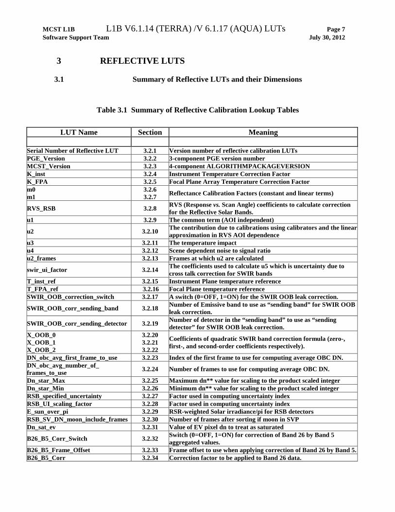
3.1 Summary of Reflective LUTs and their Dimensions
Table 3.1 Summary of Reflective Calibration Lookup Tables
LUT Name Section Meaning
Serial Number of Reflective LUT 3.2.1 Version number of reflective calibration LUTs PGE_Version 3.2.2 3-component PGE version number MCST_Version 3.2.3 4-component ALGORITHMPACKAGEVERSION K_inst 3.2.4 Instrument Temperature Correction Factor K_FPA 3.2.5 Focal Plane Array Temperature Correction Factor m0 m1
3.2.6 3.2.7 Reflectance Calibration Factors (constant and linear terms)
RVS_RSB 3.2.8 RVS (Response vs. Scan Angle) coefficients to calculate correction for the Reflective Solar Bands.
u1 3.2.9 The common term (AOI independent)
u2 3.2.10 The contribution due to calibrations using calibrators and the linear approximation in RVS AOI dependence
u3 3.2.11 The temperature impact u4 3.2.12 Scene dependent noise to signal ratio u2_frames 3.2.13 Frames at which u2 are calculated
swir_ui_factor 3.2.14 The coefficients used to calculate u5 which is uncertainty due to cross talk correction for SWIR bands
T_inst_ref 3.2.15 Instrument Plane temperature reference T_FPA_ref 3.2.16 Focal Plane temperature reference SWIR_OOB_correction_switch 3.2.17 A switch (0=OFF, 1=ON) for the SWIR OOB leak correction.
SWIR_OOB_corr_sending_band 3.2.18 Number of Emissive band to use as “sending band” for SWIR OOB leak correction.
SWIR_OOB_corr_sending_detector 3.2.19 Number of detector in the “sending band” to use as “sending detector” for SWIR OOB leak correction.
X_OOB_0 X_OOB_1 X_OOB_2
3.2.20 3.2.21 3.2.22
Coefficients of quadratic SWIR band correction formula (zero-, first-, and second-order coefficients respectively).
DN_obc_avg_first_frame_to_use 3.2.23 Index of the first frame to use for computing average OBC DN. DN_obc_avg_number_of_ frames_to_use 3.2.24 Number of frames to use for computing average OBC DN.
Dn_star_Max 3.2.25 Maximum dn** value for scaling to the product scaled integer Dn_star_Min 3.2.26 Minimum dn** value for scaling to the product scaled integer RSB_specified_uncertainty 3.2.27 Factor used in computing uncertainty index RSB_UI_scaling_factor 3.2.28 Factor used in computing uncertainty index E_sun_over_pi 3.2.29 RSR-weighted Solar irradiance/pi for RSB detectors RSB_SV_DN_moon_include_frames 3.2.30 Number of frames after sorting if moon in SVP Dn_sat_ev 3.2.31 Value of EV pixel dn to treat as saturated
B26_B5_Corr_Switch 3.2.32 Switch (0=OFF, 1=ON) for correction of Band 26 by Band 5 aggregated values.
B26_B5_Frame_Offset 3.2.33 Frame offset to use when applying correction of Band 26 by Band 5. B26_B5_Corr 3.2.34 Correction factor to be applied to Band 26 data.

MCST L1B L1B V6.1.14 (TERRA) /V 6.1.17 (AQUA) LUTs Page 8 Software Support Team July 30, 2012
Table 3.2 Dimensions used in Reflective LUTs.
Dimension macro value Meaning MAX_MCST_VERSION_BUFFER 21 Largest allowable string length MAX_PGE_VERSION_BUFFER 11 Largest allowable string length MAX_SERIAL_NUMBER_BUFFER 31 Largest allowable string length NUM_REFLECTIVE_BANDS 22 Number of reflective Solar bands. MAX_DETECTORS_PER_BAND 40 Maximum number of detectors per band.
MAX_SAMPLES_PER_BAND 4 Maximum number of subsamples per 1km frame.
NUM_MIRROR_SIDES 2 Number of mirror sides. NUM_FOCAL_PLANES 4 Number of focal plane assemblies (FPAs). NUM_SWIR_BANDS 4 Number of SWIR bands MAX_DETECTORS_PER_SWIR_BAND 20 Max. # of detectors in a SWIR band. MAX_NUM_SWIR_SUBSAMPLES 2 Max. # of subsamples in a SWIR band
NUM_REFL_INDICES 1340 Total over all reflective bands of number detectors per band*number samples per band * number mirror sides
NUM_REFLECTIVE_DETECTORS 330 Total number of reflective band detectors NUM_2ND_ORDER_COEFFS 3 Number of coefficients in an order 2 polynomial NUM_4TH_ORDER_COEFFS 5 Number of coefficients in an order 4 polynomial

MCST L1B L1B V6.1.14 (TERRA) /V 6.1.17 (AQUA) LUTs Page 9 Software Support Team July 30, 2012
3.2 Reflective LUT listing
________________________________________________________________________________
3.2.1 Serial Number of Reflective LUT This serial number serves to identify the "science content" version of the reflective lookup tables. It is stored as a string and has the form: “Rvvv yyyy:MM:dd:hh:mm”, where “R” is for reflective, “vvv” is an integer version number that gets incremented each time values of any LUT other than PGE_Version and MCST_Version are changed, and “yyyy:MM:dd:hh:mm” is the date and time of the last change to any LUT other than PGE_Version and MCST_Version. This serial number is updated as lookup tables are modified during operations. It is placed in each of the L1B Earth-view products. Name: "Serial Number of Reflective LUT" Kind: Global Attribute Data type: string Rank: 1 Dimension: MAX_SERIAL_NUMBER_BUFFER Range: N/A Fill Value: (none) ________________________________________________________________________________
3.2.2 PGE Version This LUT contains the value of PGEVERSION, written to the ECS core metadata in each of the L1B products. The format consists of “A.B.C”. The PGE version is currently synonymous with the version of the Level 1B code itself. This value only changes if there is an actual change to the code. This value is present as a LUT in the Reflective LUTs file only as a safety check. The value must match the internal code macro for the PGE version for the LUT file to be valid. Otherwise, the program will error-out. Changes in the value of PGE version do not necessarily cause a change in the Serial Number, described above. Name: "PGE Version LUT" Kind: Global Attribute Data type: string Rank: 1 Dimension: MAX_PGE_VERSION_BUFFER Range: N/A Fill Value: (none) ________________________________________________________________________________

MCST L1B L1B V6.1.14 (TERRA) /V 6.1.17 (AQUA) LUTs Page 10 Software Support Team July 30, 2012
________________________________________________________________________________
3.2.3 MCST Version This LUT contains the MCST version of Level 1B algorithms, code and LUTs. It is placed in the value of ALGORITHMPACKAGEVERSION, written to the ECS core metadata in each of the L1B products. This value is updated with each change in Level 1B, including any LUT change in any file (not just in the Reflective LUTs file). The format is a four-component number placed in a string. The first three components match the PGE_Version, described above. The fourth component will indicate the LUT update value since the last code release. Also, the string "_Terra" or "_Aqua" will be appended to the LUTs to distinguish between the different satellites. This value is placed in all three LUT files and all must agree for the set of LUT files to be valid. Otherwise, the program will error-out. Name: "MCST Version LUT" Kind: Global Attribute Data type: string Rank: 1 Dimension: MAX_MCST_VERSION_BUFFER Range: N/A Fill Value: (none) ________________________________________________________________________________
3.2.4 K_inst Instrument Temperature Correction Factor This value is used to generate a correction factor to DN. This correction factor accounts for the small dependence of detector responsivity on variations in instrument temperature. Name: "K_inst" Kind: SDS Step Function LUT Data type: float32 L1B Execution LUT HDF File Intrinsic Rank: 4 1 Dimensions: dim1: NUM_REFLECTIVE_BANDS NUM_REFL_INDICES dim2: MAX_DETECTORS_PER_BAND dim3: MAX_SAMPLES_PER_BAND dim4: NUM_MIRROR_SIDES Range: [-0.1, 0.1] Fill Value: -999 ________________________________________________________________________________
MCST L1B L1B V6.1.14 (TERRA) /V 6.1.17 (AQUA) LUTs Page 11 Software Support Team July 30, 2012
________________________________________________________________________________
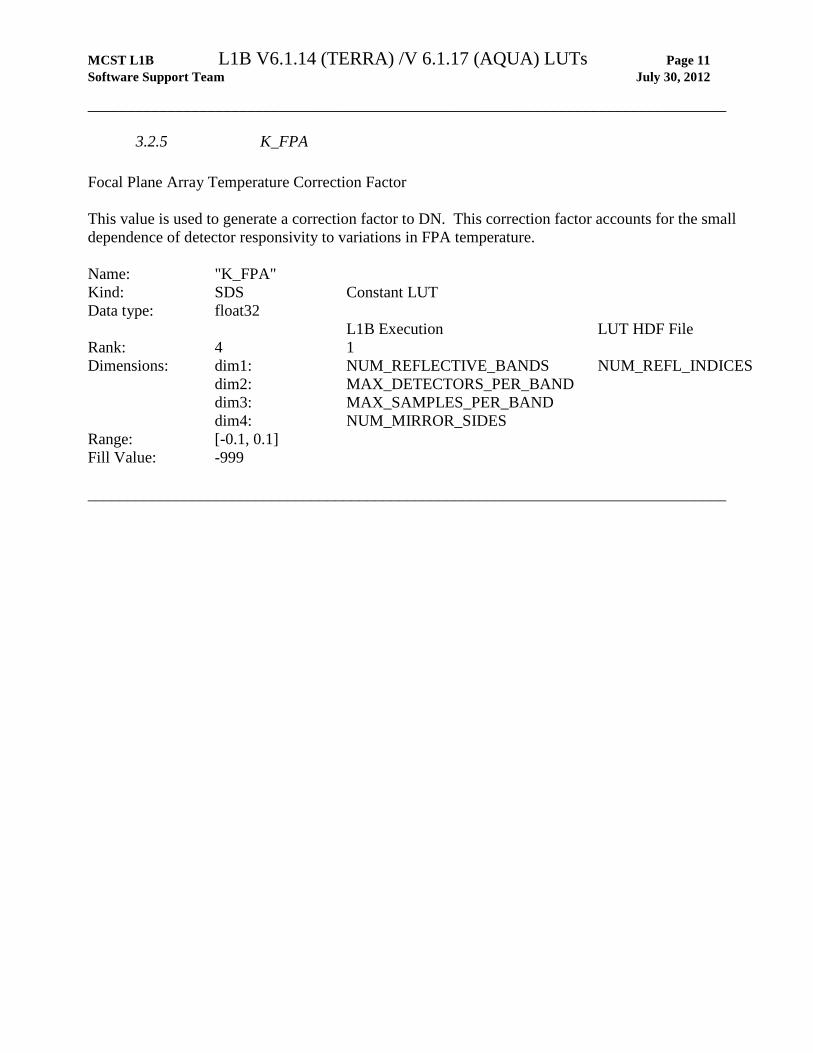
3.2.5 K_FPA Focal Plane Array Temperature Correction Factor This value is used to generate a correction factor to DN. This correction factor accounts for the small dependence of detector responsivity to variations in FPA temperature. Name: "K_FPA" Kind: SDS Constant LUT Data type: float32 L1B Execution LUT HDF File Rank: 4 1 Dimensions: dim1: NUM_REFLECTIVE_BANDS NUM_REFL_INDICES dim2: MAX_DETECTORS_PER_BAND dim3: MAX_SAMPLES_PER_BAND dim4: NUM_MIRROR_SIDES Range: [-0.1, 0.1] Fill Value: -999 ________________________________________________________________________________
MCST L1B L1B V6.1.14 (TERRA) /V 6.1.17 (AQUA) LUTs Page 12 Software Support Team July 30, 2012
________________________________________________________________________________
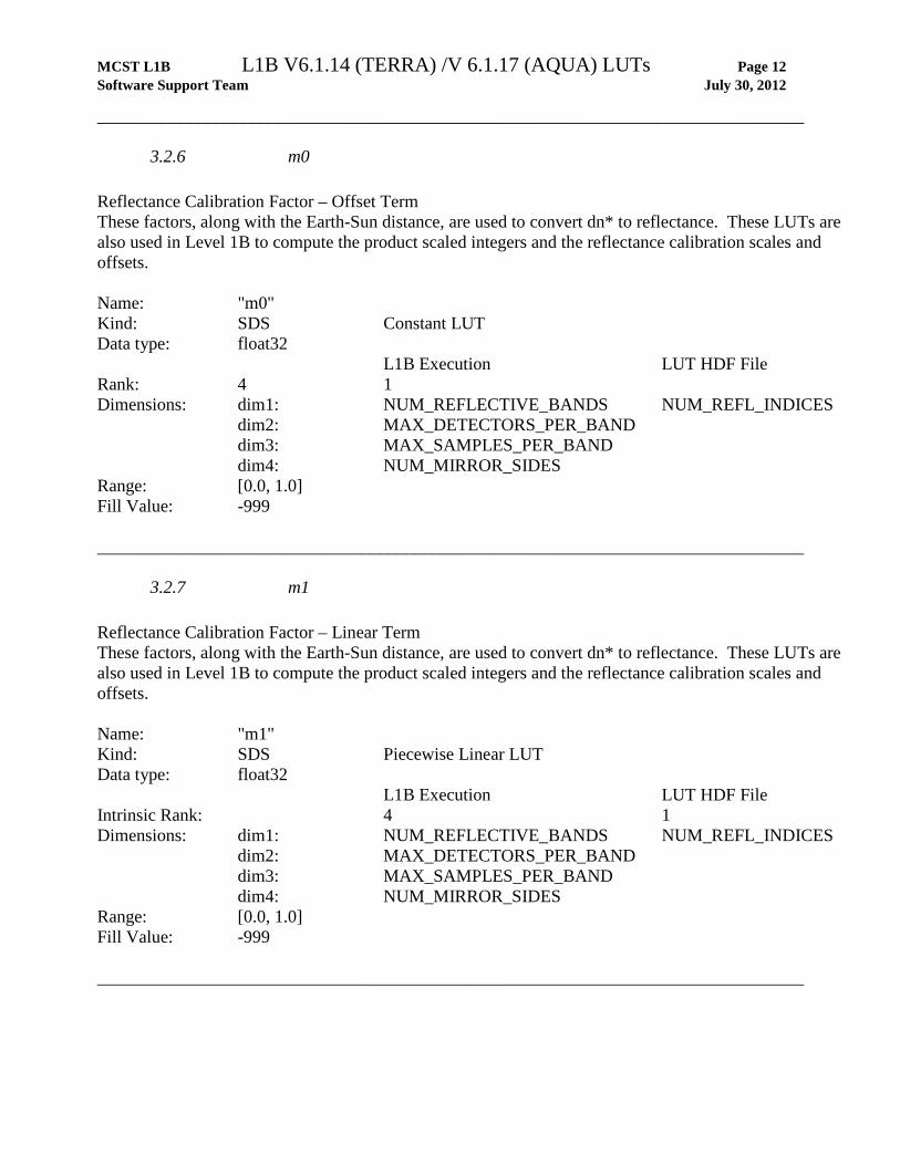
3.2.6 m0 Reflectance Calibration Factor – Offset Term These factors, along with the Earth-Sun distance, are used to convert dn* to reflectance. These LUTs are also used in Level 1B to compute the product scaled integers and the reflectance calibration scales and offsets. Name: "m0" Kind: SDS Constant LUT Data type: float32 L1B Execution LUT HDF File Rank: 4 1 Dimensions: dim1: NUM_REFLECTIVE_BANDS NUM_REFL_INDICES dim2: MAX_DETECTORS_PER_BAND dim3: MAX_SAMPLES_PER_BAND dim4: NUM_MIRROR_SIDES Range: [0.0, 1.0] Fill Value: -999 ________________________________________________________________________________
3.2.7 m1 Reflectance Calibration Factor – Linear Term These factors, along with the Earth-Sun distance, are used to convert dn* to reflectance. These LUTs are also used in Level 1B to compute the product scaled integers and the reflectance calibration scales and offsets. Name: "m1" Kind: SDS Piecewise Linear LUT Data type: float32 L1B Execution LUT HDF File Intrinsic Rank: 4 1 Dimensions: dim1: NUM_REFLECTIVE_BANDS NUM_REFL_INDICES dim2: MAX_DETECTORS_PER_BAND dim3: MAX_SAMPLES_PER_BAND dim4: NUM_MIRROR_SIDES Range: [0.0, 1.0] Fill Value: -999 ________________________________________________________________________________
MCST L1B L1B V6.1.14 (TERRA) /V 6.1.17 (AQUA) LUTs Page 13 Software Support Team July 30, 2012
________________________________________________________________________________
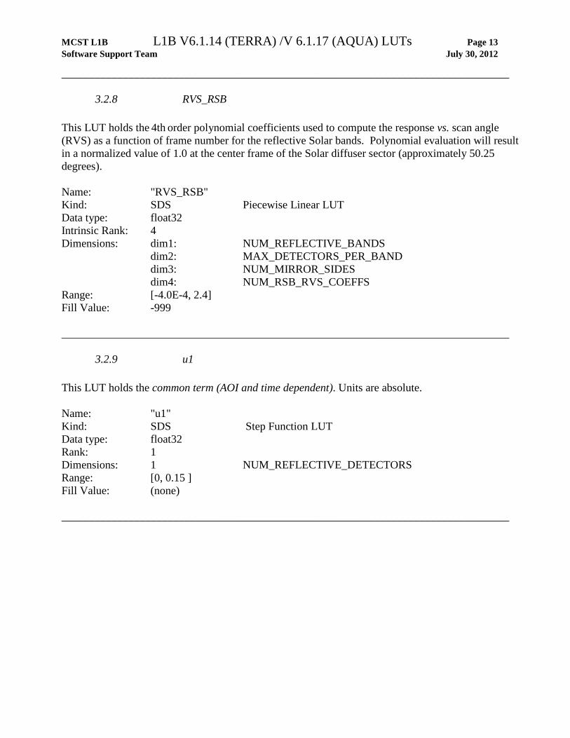
3.2.8 RVS_RSB This LUT holds the 4th order polynomial coefficients used to compute the response vs. scan angle (RVS) as a function of frame number for the reflective Solar bands. Polynomial evaluation will result in a normalized value of 1.0 at the center frame of the Solar diffuser sector (approximately 50.25 degrees). Name: "RVS_RSB" Kind: SDS Piecewise Linear LUT Data type: float32 Intrinsic Rank: 4 Dimensions: dim1: NUM_REFLECTIVE_BANDS dim2: MAX_DETECTORS_PER_BAND dim3: NUM_MIRROR_SIDES dim4: NUM_RSB_RVS_COEFFS Range: [-4.0E-4, 2.4] Fill Value: -999 ________________________________________________________________________________
3.2.9 u1 This LUT holds the common term (AOI and time dependent). Units are absolute. Name: "u1" Kind: SDS Step Function LUT Data type: float32 Rank: 1 Dimensions: 1 NUM_REFLECTIVE_DETECTORS Range: [0, 0.15 ] Fill Value: (none) ________________________________________________________________________________
MCST L1B L1B V6.1.14 (TERRA) /V 6.1.17 (AQUA) LUTs Page 14 Software Support Team July 30, 2012
________________________________________________________________________________
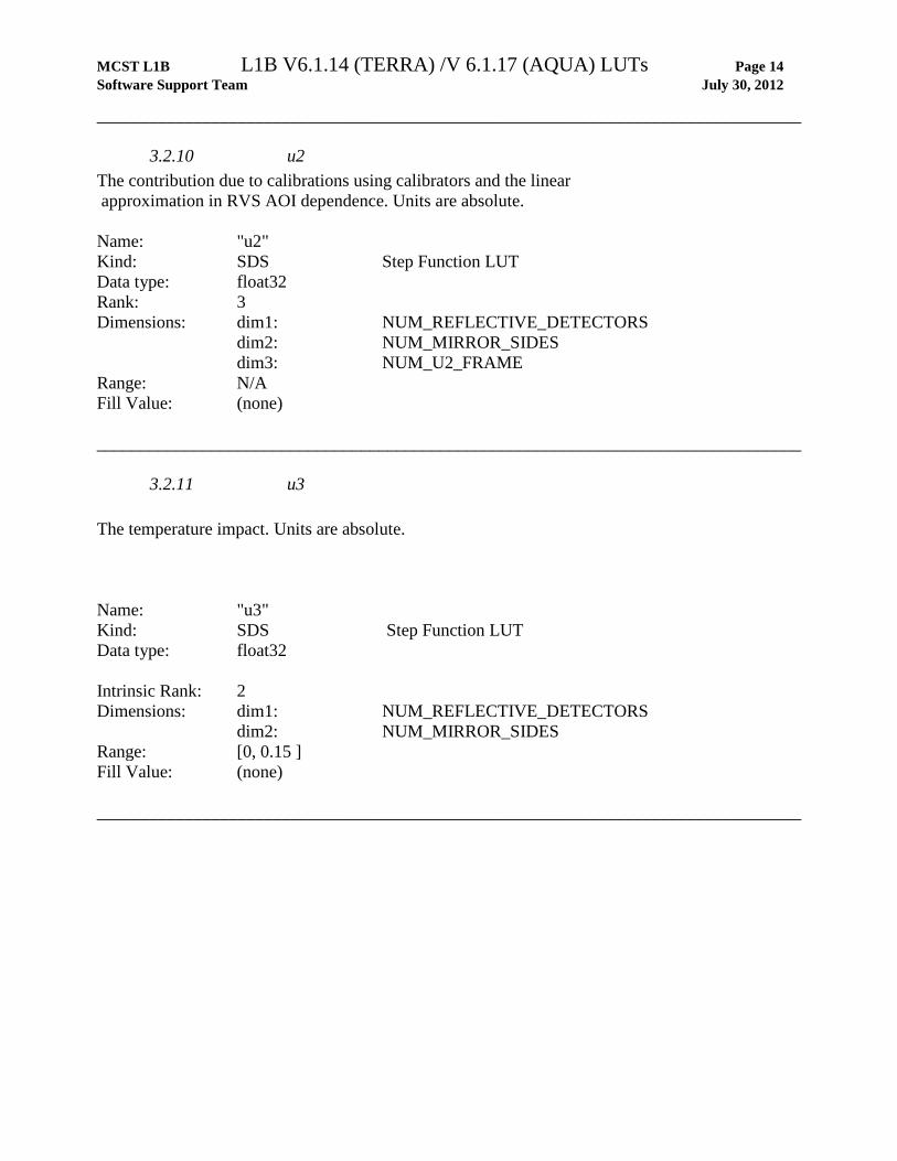
3.2.10 u2 The contribution due to calibrations using calibrators and the linear approximation in RVS AOI dependence. Units are absolute. Name: "u2" Kind: SDS Step Function LUT Data type: float32 Rank: 3 Dimensions: dim1: NUM_REFLECTIVE_DETECTORS dim2: NUM_MIRROR_SIDES dim3: NUM_U2_FRAME Range: N/A Fill Value: (none) ________________________________________________________________________________
3.2.11 u3 The temperature impact. Units are absolute. Name: "u3" Kind: SDS Step Function LUT Data type: float32 Intrinsic Rank: 2 Dimensions: dim1: NUM_REFLECTIVE_DETECTORS dim2: NUM_MIRROR_SIDES Range: [0, 0.15 ] Fill Value: (none) ________________________________________________________________________________

MCST L1B L1B V6.1.14 (TERRA) /V 6.1.17 (AQUA) LUTs Page 15 Software Support Team July 30, 2012
________________________________________________________________________________
3.2.12 u4 This LUT holds the scene dependent noise to signal ratio. Units are absolute. Name: "u4" Kind: SDS Step Function LUT Data type: float32 Intrinsic Rank: 5 Dimensions: dim1: NUM_REFLECTIVE_BANDS dim2: MAX_DETECTORS_PER_BAND dim3: MAX_SAMPLES_PER_BAND dim4: NUM_MIRROR_SIDES dim5: NUM_2ND_ORDER_COEFFS Range: N/A Fill Value: -999 ________________________________________________________________________________
3.2.13 u2_frames This LUT holds the frames at which U2 are calculated. Units are absolute. Name: "u2_frames" Kind: SDS Constant LUT Data type: float32 Rank: 1 Dimension: 1 NUM_U2_FRAME Range: [0, 1353] Fill Value: (none) ________________________________________________________________________________

MCST L1B L1B V6.1.14 (TERRA) /V 6.1.17 (AQUA) LUTs Page 16 Software Support Team July 30, 2012
________________________________________________________________________________
3.2.14 swir_ui_factor These values are used to calculate u5 which is uncertainty ascribed due to cross-talk correction for SWIR bands. Units are absolute. Name: "swir_ui_factor" Kind: SDS Constant LUT Data type: float32 Rank: 1 Dimensions: 1 NUM_SWIR_BANDS Range: [0, 1] Fill Value: (none) ________________________________________________________________________________
3.2.15 T_inst_ref Instrument temperature reference This value is the instrument reference temperature (in Kelvins) to use when correcting DN for effects of instrument temperature on detector responsivity. Name: "T_inst_ref" Kind: SDS Step Function LUT Data type: float32 Intrinsic Rank: 1 Dimension: 1 Range: [250, 300] Fill Value: (none) ________________________________________________________________________________
MCST L1B L1B V6.1.14 (TERRA) /V 6.1.17 (AQUA) LUTs Page 17 Software Support Team July 30, 2012
________________________________________________________________________________
3.2.16 T_FPA_ref Focal Plane temperature reference These values are the focal plane assembly (FPA) reference temperatures (in Kelvins) to use when correcting DN for effects of FPA temperature on detector responsivity. Name: "T_FPA_ref" Kind: SDS Constant LUT Data type: float32 Rank: 1 Dimension: NUM_FOCAL_PLANES Range: [80, 300] Fill Value: (none) Note: the order of the focal planes in the array is: VIS, NIR, SMIR, LWIR. ________________________________________________________________________________
3.2.17 SWIR_OOB_correction_switch This LUT defines whether the SWIR out-of-band (OOB) leak correction to dn is applied. If this correction switch is set to 0 (OFF), then the correction will not be applied regardless of the values in the LUTs relating to this correction (see X_OOB_0, Section 3.2.20, X_OOB_1, Section 3.2.21, and X_OOB_2, Section 3.2.22). Name: "SWIR_OOB_correction_switch" Kind: SDS Step Function LUT Data type: int16 Intrinsic Rank: 1 Dimension: 1 Range: [0, 1] Fill Value: (none) ________________________________________________________________________________

MCST L1B L1B V6.1.14 (TERRA) /V 6.1.17 (AQUA) LUTs Page 18 Software Support Team July 30, 2012
________________________________________________________________________________
3.2.18 SWIR_OOB_corr_sending_band This LUT defines the number of the “sending band” for the SWIR out-of-band (OOB) leak correction. It is normally set to Band 25 for MODIS/Aqua and Band 28 for MODIS/Terra. See X_OOB_0, Section 3.2.20, X_OOB_1, Section 3.2.21, and X_OOB_2, Section 3.2.22. Name: "SWIR_OOB_corr_sending_band " Kind: SDS Step Function LUT Data type: int16 Intrinsic Rank: 1 Dimension: 1 Range: [20, 36] Fill Value: (none) ________________________________________________________________________________
3.2.19 SWIR_OOB_corr_sending_detector This LUT defines the number of the detector in the “sending band” to use as “sending” detector for the SWIR out-of-band (OOB) leak correction. Name: "SWIR_OOB_corr_sending_detector " Kind: SDS Step Function LUT Data type: int16 Intrinsic Rank: 1 Dimension: DETECTORS_PER_1KM_BAND Range: [0, 9] Fill Value: (none) ________________________________________________________________________________
MCST L1B L1B V6.1.14 (TERRA) /V 6.1.17 (AQUA) LUTs Page 19 Software Support Team July 30, 2012
________________________________________________________________________________
3.2.20 X_OOB_0 This LUT contains the constant coefficient of the quadratic relation empirically derived between the SWIR OOB correction sending band (“Band X”, see Section 3.2.18 above) dn, dnx, and the correction to the SWIR band, dncorr. The correction is applied as:
dn = dn – dncorr where
dncorr = XOOB0 + XOOB
1 * dnx + XOOB2 * dnx
2
Name: "X_OOB_0" Kind: SDS Constant LUT Data type: float32 Rank: 4 Dimensions: dim1: NUM_SWIR_BANDS dim2: MAX_DETECTORS_PER_SWIR_BAND dim3: MAX_NUM_SWIR_SUBSAMPLES dim4: NUM_MIRROR_SIDES Range: [-100, 100] Fill Value: -999 ________________________________________________________________________________

MCST L1B L1B V6.1.14 (TERRA) /V 6.1.17 (AQUA) LUTs Page 20 Software Support Team July 30, 2012
________________________________________________________________________________
3.2.21 X_OOB_1 This LUT contains the first order coefficient of the quadratic relation empirically derived between the SWIR OOB correction sending band (“Band X”) dn, dnx, and the correction to the SWIR band, dncorr. See X_OOB_0 above (Section 3.2.20) for how the correction is applied. Name: "X_OOB_1" Kind: SDS Step Function LUT Data type: float32 Intrinsic Rank: 4 Dimensions: dim1: NUM_SWIR_BANDS dim2: MAX_DETECTORS_PER_SWIR_BAND dim3: MAX_NUM_SWIR_SUBSAMPLES dim4: NUM_MIRROR_SIDES Range: [-100, 100] Fill Value: -999
3.2.22 X_OOB_2 This LUT contains the second order coefficient of the quadratic relation empirically derived between the SWIR OOB correction sending band (“Band X”) dn, dnx, and the correction to the SWIR band, dncorr. See X_OOB_0 above (Section 3.2.20) for how the correction is applied. Name: "X_OOB_2" Kind: SDS Constant LUT Data type: float32 Rank: 4 Dimensions: dim1: NUM_SWIR_BANDS dim2: MAX_DETECTORS_PER_SWIR_BAND dim3: MAX_NUM_SWIR_SUBSAMPLES dim4: NUM_MIRROR_SIDES Range: [-100, 100] Fill Value: -999 ________________________________________________________________________________
MCST L1B L1B V6.1.14 (TERRA) /V 6.1.17 (AQUA) LUTs Page 21 Software Support Team July 30, 2012
________________________________________________________________________________
3.2.23 DN_obc_avg_first_frame_to_use Name: "DN_obc_avg_first_frame_to_use" Kind: SDS Constant LUT Data type: int16 Rank: 1 Dimension: 1 Range: [0, 49] Fill Value: (none) Value: Presently set to 10. ________________________________________________________________________________
3.2.24 DN_obc_avg_number_of_frames_to_use This LUT holds the index (0 through N-1) of the first frame to use in computing the average OBC DN, used as a zero-point value in the reflective Solar band calibration algorithms. The space-view (SV) DN is typically used in calculating this number. However, if the moon is in the SV keep-out-box or there is some other problem with the SV data, the blackbody (BB) DNs are used. Name: "DN_obc_avg_number_of_frames_to_use" Kind: SDS Constant LUT Data type: int16 Rank: 1 Dimension: 1 Range: [1, 50] Fill Value: (none) Value: Presently set to 30. ________________________________________________________________________________

MCST L1B L1B V6.1.14 (TERRA) /V 6.1.17 (AQUA) LUTs Page 22 Software Support Team July 30, 2012
________________________________________________________________________________
3.2.25 dn_star_Max This value defines the upper limit of the dynamic range of dn** for the purpose of scaling to the product scaled integer. The name of this is somewhat misleading since we scale dn**, not dn*, to the product scaled integer. Name: "dn_star_Max" Kind: SDS Constant LUT Data type: float32 Rank: 1 Dimension: NUM_REFLECTIVE_BANDS Range: [4095, 4095] Fill Value: (none) Values: Derived pre-launch. The value for each band is 4095. ________________________________________________________________________________
3.2.26 dn_star_Min This value defines the lower limit of the dynamic range of dn** for the purpose of scaling to the product scaled integer. (See other comments above for dn_star_Max). Name: "dn_star_Min" Kind: SDS Constant LUT Data type: float32 Rank: 1 Dimension: NUM_REFLECTIVE_BANDS Range: [-40, 0] Fill Value: (none) Values: Derived pre-launch. For Bands 1-7, the value is 0 (zero). For other bands, the
value is -40. If the nadir aperture door is closed on any scan in the granule, then the values in this LUT for Bands 1-7 will be dynamically over-written by the L1B code and re-set to -40.
________________________________________________________________________________

MCST L1B L1B V6.1.14 (TERRA) /V 6.1.17 (AQUA) LUTs Page 23 Software Support Team July 30, 2012
________________________________________________________________________________
3.2.27 RSB_specified_uncertainty This LUT contains the specified uncertainty factor for each reflective Solar band, which is used along with the scaling factor described by the LUT "RSB_UI_scaling_factor" (see Section 3.2.28) to convert percent uncertainty to an uncertainty index. Name: "RSB_specified_uncertainty" Kind: SDS Constant LUT Data type: float32 Rank: 1 Dimension: NUM_REFLECTIVE_BANDS Range: N/A Fill Value: (none) ________________________________________________________________________________
3.2.28 RSB_UI_scaling_factor This LUT contains the uncertainty scaling factor for each reflective Solar band, which is used along with the calculated uncertainty described by the LUT "RSB_specified_uncertainty" (see Section 3.2.27) to convert percent uncertainty to an uncertainty index. The formula for uncertainty index (UI) in terms of uncertainty_in_percent, specified_uncertainty, and scaling_factor is: UI = scaling_factor * ln (uncertainty_in_percent / specified_uncertainty) where "ln" is the natural logarithm. The uncertainty in percent is computed within the Level 1B code dynamically. Name: "RSB_UI_scaling_factor" Kind: SDS Constant LUT Data type: float32 Rank: 1 Dimension: NUM_REFLECTIVE_BANDS Range: N/A Fill Value: (none) ________________________________________________________________________________
MCST L1B L1B V6.1.14 (TERRA) /V 6.1.17 (AQUA) LUTs Page 24 Software Support Team July 30, 2012
________________________________________________________________________________
3.2.29 E_sun_over_pi For each RSB detector, this LUT contains the Solar irradiance at 1 AU divided by π and weighted by the detector's relative spectral response (RSR). Name: "E_sun_over_pi" Kind: SDS Constant LUT Data type: float32 Rank: 1 Dimension: NUM_REFLECTIVE_DETECTORS Range: N/A Fill Value: (none) ________________________________________________________________________________
3.2.30 RSB_SV_DN_moon_include_frames This LUT holds the number of frames to use when calculating average space-view (SV) DN when the moon is in the SV keep-out box (KOB). If the moon is determined to be in the SV KOB, the 50 SV DN frames are sorted from the lowest to the highest values. The lowest "RSB_SV_DN_moon_include_frames" are used to calculate average SV DN using the same logic as is done for the case when the moon is not in the SV KOB. Name: "RSB_SV_DN_moon_include_frames" Kind: SDS Constant LUT Data type: int16 Rank: 1 Dimension: 1 Range: [0, 50] Fill Value: (none) ________________________________________________________________________________
MCST L1B L1B V6.1.14 (TERRA) /V 6.1.17 (AQUA) LUTs Page 25 Software Support Team July 30, 2012
________________________________________________________________________________
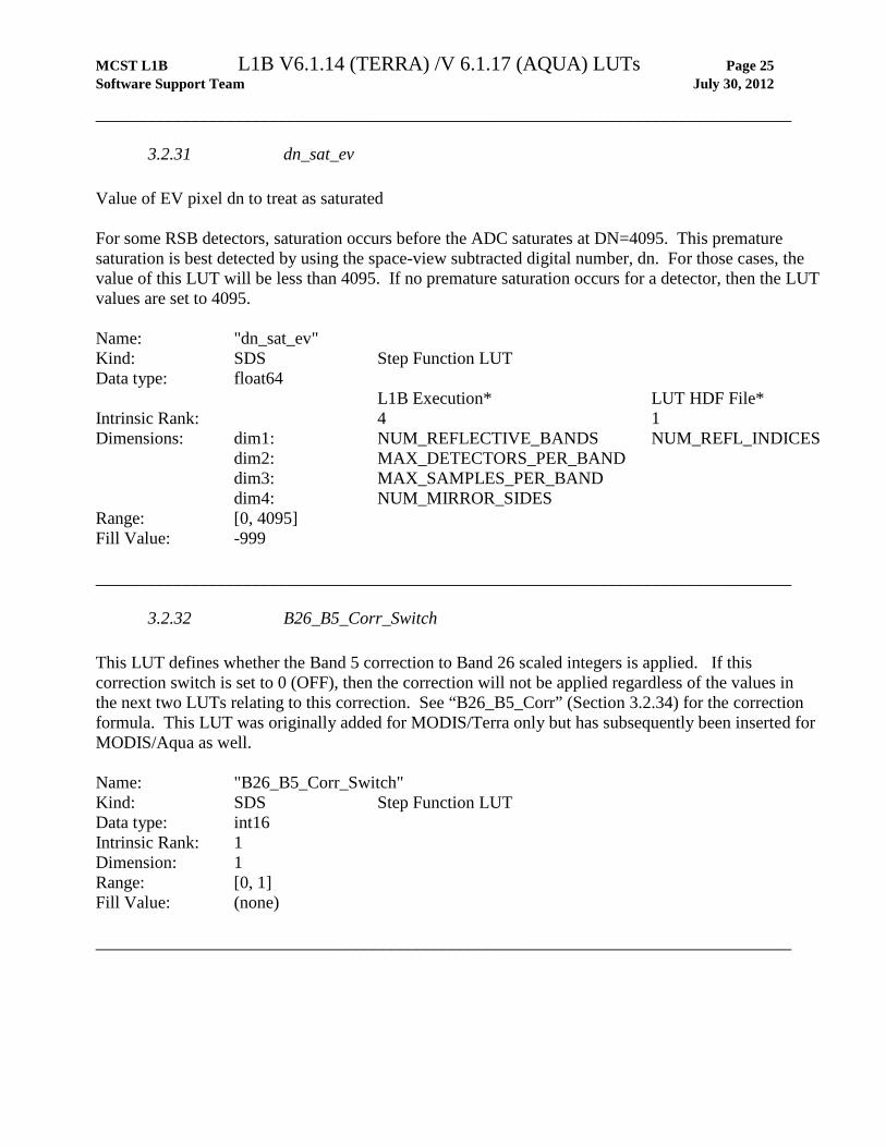
3.2.31 dn_sat_ev Value of EV pixel dn to treat as saturated For some RSB detectors, saturation occurs before the ADC saturates at DN=4095. This premature saturation is best detected by using the space-view subtracted digital number, dn. For those cases, the value of this LUT will be less than 4095. If no premature saturation occurs for a detector, then the LUT values are set to 4095. Name: "dn_sat_ev" Kind: SDS Step Function LUT Data type: float64 L1B Execution* LUT HDF File* Intrinsic Rank: 4 1 Dimensions: dim1: NUM_REFLECTIVE_BANDS NUM_REFL_INDICES dim2: MAX_DETECTORS_PER_BAND dim3: MAX_SAMPLES_PER_BAND dim4: NUM_MIRROR_SIDES Range: [0, 4095] Fill Value: -999 ________________________________________________________________________________
3.2.32 B26_B5_Corr_Switch This LUT defines whether the Band 5 correction to Band 26 scaled integers is applied. If this correction switch is set to 0 (OFF), then the correction will not be applied regardless of the values in the next two LUTs relating to this correction. See “B26_B5_Corr” (Section 3.2.34) for the correction formula. This LUT was originally added for MODIS/Terra only but has subsequently been inserted for MODIS/Aqua as well. Name: "B26_B5_Corr_Switch" Kind: SDS Step Function LUT Data type: int16 Intrinsic Rank: 1 Dimension: 1 Range: [0, 1] Fill Value: (none) ________________________________________________________________________________

MCST L1B L1B V6.1.14 (TERRA) /V 6.1.17 (AQUA) LUTs Page 26 Software Support Team July 30, 2012
________________________________________________________________________________
3.2.33 B26_B5_Frame_Offset This LUT gives the frame offsets used in calculating the Band 5 correction to Band 26 scaled integers (SIs). See “B26_B5_Corr” (Section 3.2.34) for the correction formula. This LUT was originally added for MODIS/Terra only but has subsequently been inserted for MODIS/Aqua as well. Name: “B26_B5_Frame_Offset” Kind: SDS Constant LUT Data type: int16 Rank: 1 Dimension: DETECTORS_PER_1KM_BAND Range: [-10, 10] Fill Value: -999 ________________________________________________________________________________
MCST L1B L1B V6.1.14 (TERRA) /V 6.1.17 (AQUA) LUTs Page 27 Software Support Team July 30, 2012
________________________________________________________________________________
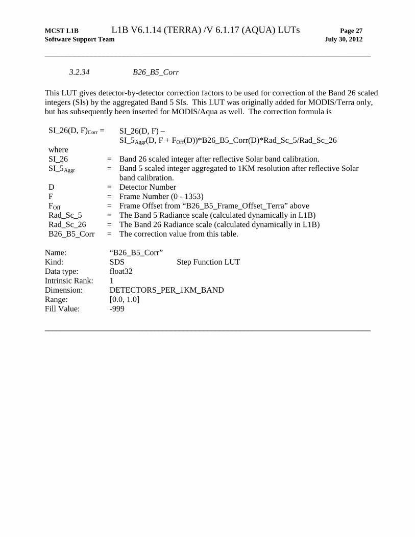
3.2.34 B26_B5_Corr This LUT gives detector-by-detector correction factors to be used for correction of the Band 26 scaled integers (SIs) by the aggregated Band 5 SIs. This LUT was originally added for MODIS/Terra only, but has subsequently been inserted for MODIS/Aqua as well. The correction formula is SI_26(D, F)Corr = SI_26(D, F) −
SI_5Aggr(D, F + FOff(D))*B26_B5_Corr(D)*Rad_Sc_5/Rad_Sc_26 where SI_26 = Band 26 scaled integer after reflective Solar band calibration. SI_5Aggr = Band 5 scaled integer aggregated to 1KM resolution after reflective Solar
band calibration. D = Detector Number F = Frame Number (0 - 1353) FOff = Frame Offset from “B26_B5_Frame_Offset_Terra” above Rad_Sc_5 = The Band 5 Radiance scale (calculated dynamically in L1B) Rad_Sc_26 = The Band 26 Radiance scale (calculated dynamically in L1B) B26_B5_Corr = The correction value from this table.
Name: “B26_B5_Corr” Kind: SDS Step Function LUT Data type: float32 Intrinsic Rank: 1 Dimension: DETECTORS_PER_1KM_BAND Range: [0.0, 1.0] Fill Value: -999 ________________________________________________________________________________

MCST L1B L1B V6.1.14 (TERRA) /V6.1.17 (AQUA) LUTs Page 28 Software Support Team July 30, 2012
4 EMISSIVE LUTS
4.1 Summary of Emissive LUTs and their Dimensions
Table 4.1 Summary of Emissive Calibration Lookup Tables
LUT name Section Meaning Serial Number of Emissive LUT 4.2.1 Version number of emissive calibration LUTs PGE_Version 4.2.2 3-component PGE version number
MCST_Version 4.2.3 4-component version, placed in ALGORITHMPACKAGEVERSION
Epsilon_cav 4.2.4 Effective cavity emissivity. epsilon_bb 4.2.5 Blackbody emissivity. Delta_T_bb_beta 4.2.6 The "β" term in the equation for calculating ∆T_bb. Delta_T_bb_delta 4.2.7 The "∆" term in the equation for calculating ∆T_bb. RSR 4.2.8 Relative spectral responses WAVELENGTH 4.2.9 Wavelengths at points of RSRs NWL 4.2.10 Number of values in RSR distribution. A0 A2
4.2.11 4.2.12 Quadratic coefficients for calculating a0 and a2.
Sigma_a0 Sigma_a2
4.2.13 4.2.14
Coefficients of polynomial fit of uncertainty weight vs. DN.Uncertainty due to a0/a2
Sigma_b1_B21 4.2.15 Uncertainty due to Band 21 b1 Sigma_epsilon_bb Sigma_epsilon_cav
4.2.16 4.2.17 Uncertainty due to BB andCavity Emissivity
Sigma_L_Tbb 4.2.18 Uncertainty due to BB Temperature Sigma_L_Tcav 4.2.19 Uncertainty due to Cavity Temperature Sigma_L_Tsm 4.2.20 Uncertainty due to Scan Mirror Temperature Sigma_L_lambda 4.2.21 Uncertainty due to Lambda Sigma_RVS_ev 4.2.22 Uncertainty due to EV RVS pcx_ui_factor 4.2.23 Uncertainty due to PCX (B32-36) BB_DN_first_frame_to_use 4.2.24 Index of 1st frame for computing BB DN averages BB_DN_number_of_frames_to_use 4.2.25 Number of frames for computing BB DN averages SV_DN_first_frame_to_use 4.2.26 Index of 1st frame for computing SV DN averages SV_DN_number_of_frames_to_use 4.2.27 Number of frames for computing SV DN averages SV_DN_moon_include_frames 4.2.28 Number of frames after sorting if moon in SVP
Num_overlap_scans_b1 4.2.29 Number of scans in leading and trailing granules for cross-granule averaging of b1
T_ins_function_flag 4.2.30 Identifies suitable instrument temperature thermistors.
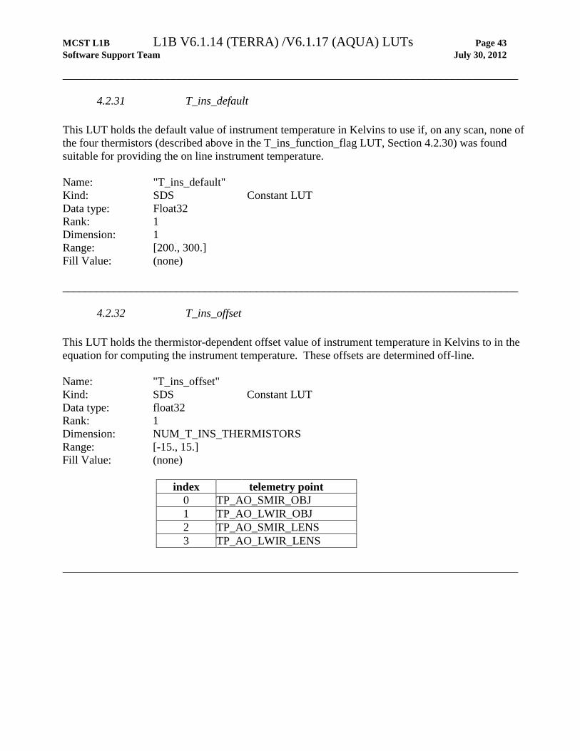
T_ins_default 4.2.31 Default value of instrument temperature in Kelvins T_ins_offset 4.2.32 Instrument temperature offset in Kelvins. T_cav_function_flag 4.2.33 Identifies suitable cavity temperature thermistors. T_cav_default 4.2.34 Default value of cavity temperature in Kelvins T_mir_function_flag 4.2.35 Identifies suitable mirror temperature thermistors. T_mir_default 4.2.36 Default value of mirror temperature in Kelvins
BB_Weight 4.2.37 Weight factor used for computing average BB temperature.
RVS_TEB 4.2.38 Polynomial coefficients to calculate RVS correction for thermal Emissive Bands
RVS_BB_SV_Frame_No 4.2.39 Reference frame numbers to use when calculating the blackbody and space view RVS corrections respectively.
Band_21_b1 4.2.40 The value of b1 for each Band 21 detector. L_Max 4.2.41 Top end of radiance dynamic range L_Min 4.2.42 Bottom end of radiance dynamic range

MCST L1B L1B V6.1.14 (TERRA) /V6.1.17 (AQUA) LUTs Page 29 Software Support Team July 30, 2012
LUT name Section Meaning TEB_specified_uncertainty 4.2.43 Factor used in computing uncertainty index TEB_UI_scaling_factor 4.2.44 Factor used in computing uncertainty index PC_XT 4.2.45 PC bands cross-talk correction parameters. PCX_correction_switch 4.2.46 Switch (0=OFF, 1=ON) for crosstalk correction BB_T_sat_default_b1_c1_aqua 4.2.47 MODIS/AQUA only. C1 is b1 vs T_lwir rate (linear).
BB_T_sat_default_b1_Tlwir_baseline_aqua 4.2.48 MODIS/AQUA only. Tlwir baseline is currently set as 83K.
BB_T_sat_default_b1_baseline_aqua 4.2.49 MODIS/AQUA only. Default b1 value is T_lwir dependent which oscillates in orbital basis.
BB_T_sat_switch_aqua 4.2.50 MODIS/AQUA only. Determines whether or not to use default b1
MCST L1B L1B V6.1.14 (TERRA) /V6.1.17 (AQUA) LUTs Page 30 Software Support Team July 30, 2012
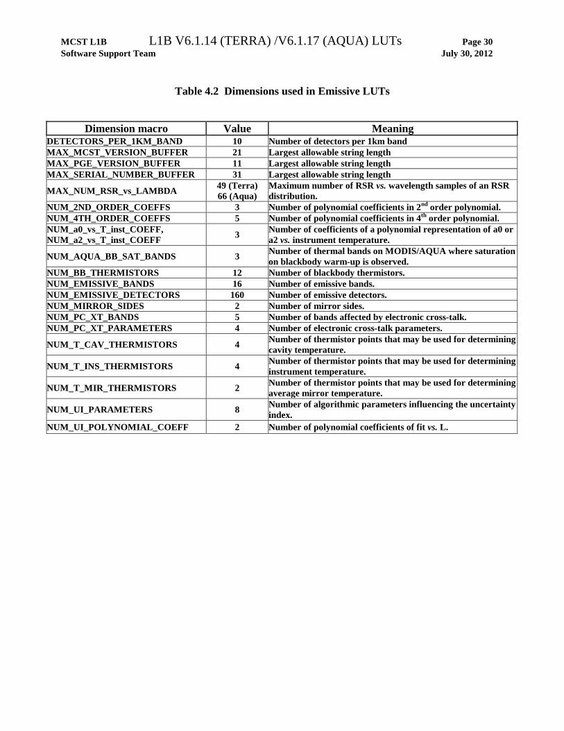
Table 4.2 Dimensions used in Emissive LUTs
Dimension macro Value Meaning DETECTORS_PER_1KM_BAND 10 Number of detectors per 1km band MAX_MCST_VERSION_BUFFER 21 Largest allowable string length MAX_PGE_VERSION_BUFFER 11 Largest allowable string length MAX_SERIAL_NUMBER_BUFFER 31 Largest allowable string length
MAX_NUM_RSR_vs_LAMBDA 49 (Terra) 66 (Aqua)
Maximum number of RSR vs. wavelength samples of an RSR distribution.
NUM_2ND_ORDER_COEFFS 3 Number of polynomial coefficients in 2nd order polynomial. NUM_4TH_ORDER_COEFFS 5 Number of polynomial coefficients in 4th order polynomial. NUM_a0_vs_T_inst_COEFF, NUM_a2_vs_T_inst_COEFF 3 Number of coefficients of a polynomial representation of a0 or
a2 vs. instrument temperature.
NUM_AQUA_BB_SAT_BANDS 3 Number of thermal bands on MODIS/AQUA where saturation on blackbody warm-up is observed.
NUM_BB_THERMISTORS 12 Number of blackbody thermistors. NUM_EMISSIVE_BANDS 16 Number of emissive bands. NUM_EMISSIVE_DETECTORS 160 Number of emissive detectors. NUM_MIRROR_SIDES 2 Number of mirror sides. NUM_PC_XT_BANDS 5 Number of bands affected by electronic cross-talk. NUM_PC_XT_PARAMETERS 4 Number of electronic cross-talk parameters.
NUM_T_CAV_THERMISTORS 4 Number of thermistor points that may be used for determining cavity temperature.
NUM_T_INS_THERMISTORS 4 Number of thermistor points that may be used for determining instrument temperature.
NUM_T_MIR_THERMISTORS 2 Number of thermistor points that may be used for determining average mirror temperature.
NUM_UI_PARAMETERS 8 Number of algorithmic parameters influencing the uncertainty index.
NUM_UI_POLYNOMIAL_COEFF 2 Number of polynomial coefficients of fit vs. L.

MCST L1B L1B V6.1.14 (TERRA) /V6.1.17 (AQUA) LUTs Page 31 Software Support Team July 30, 2012
4.2 Emissive LUT Listing ________________________________________________________________________________
4.2.1 Serial Number of Emissive LUT This serial number serves to identify the "science content" version of the emissive lookup tables. It is stored as a string and has the form: “Evvv yyyy:MM:dd:hh:mm”, where “E” is for emissive, “vvv” is an integer version number that gets incremented each time values of any LUT other than PGE_Version and MCST_Version are changed, and “yyyy:MM:dd:hh:mm” is the date and time of the last change to any LUT other than PGE_Version and MCST_Version. This serial number is updated as lookup tables are modified during operations. It is placed in each of the L1B Earth-view products. Name: "Serial Number of Emissive LUT" Kind: Global Attribute Data type: string Rank: 1 Dimension: MAX_SERIAL_NUMBER_BUFFER Range: N/A Fill Value: (none) ________________________________________________________________________________
4.2.2 PGE Version This LUT contains the value of PGEVERSION, written to the ECS core metadata in each of the L1B products (see amplified description in Section 3.2.2). Name: "PGE Version LUT" Kind: Global Attribute Data type: String Rank: 1 Dimension: MAX_PGE_VERSION_BUFFER Range: N/A Fill Value: (none) ________________________________________________________________________________
MCST L1B L1B V6.1.14 (TERRA) /V6.1.17 (AQUA) LUTs Page 32 Software Support Team July 30, 2012
________________________________________________________________________________
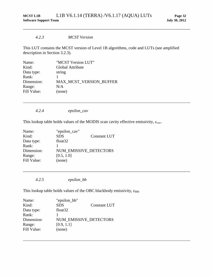
4.2.3 MCST Version This LUT contains the MCST version of Level 1B algorithms, code and LUTs (see amplified description in Section 3.2.3). Name: "MCST Version LUT" Kind: Global Attribute Data type: string Rank: 1 Dimension: MAX_MCST_VERSION_BUFFER Range: N/A Fill Value: (none) ________________________________________________________________________________
4.2.4 epsilon_cav This lookup table holds values of the MODIS scan cavity effective emissivity, εcav. Name: "epsilon_cav" Kind: SDS Constant LUT Data type: float32 Rank: 1 Dimension: NUM_EMISSIVE_DETECTORS Range: [0.5, 1.0] Fill Value: (none) ________________________________________________________________________________
4.2.5 epsilon_bb This lookup table holds values of the OBC blackbody emissivity, εBB. Name: "epsilon_bb" Kind: SDS Constant LUT Data type: float32 Rank: 1 Dimension: NUM_EMISSIVE_DETECTORS Range: [0.9, 1.1] Fill Value: (none) ________________________________________________________________________________
MCST L1B L1B V6.1.14 (TERRA) /V6.1.17 (AQUA) LUTs Page 33 Software Support Team July 30, 2012
________________________________________________________________________________
4.2.6 delta_T_bb_beta This value represents "β", used for calculating a correction to the OBC blackbody temperature. Name: "delta_T_bb_beta" Kind: SDS Constant LUT Data type: float32 Rank: 1 Dimension: NUM_EMISSIVE_DETECTORS Range: [-0.5, 0.5] Fill Value: (none) ________________________________________________________________________________
4.2.7 delta_T_bb_delta This value represents the additional "∆" term at the end of the equation used for calculating a correction to the OBC blackbody temperature. Name: "delta_T_bb_delta" Kind: SDS Constant LUT Data type: float32 Rank: 1 Dimension: NUM_EMISSIVE_DETECTORS Range: [-0.5, 0.5] Fill Value: (none) ________________________________________________________________________________
4.2.8 RSR This LUT holds a discrete approximation to the relative spectral response (RSR) curve for each of the emissive band detectors. Each emissive detector’s RSR is given by these values for a given number of wavelengths (specified by the “NWL” LUT; see Section 4.2.10) and the wavelength values are given by the “Wavelength” LUT (see Section 4.2.9). Name: "RSR" Kind: SDS Constant LUT Data type: float32 Rank: 2 Dimensions: dim1: NUM_EMISSIVE_DETECTORS dim2: MAX_NUM_RSR_vs_LAMBDA Range: [ 0.01, 1.0] Fill Value: 0.0 ________________________________________________________________________________
MCST L1B L1B V6.1.14 (TERRA) /V6.1.17 (AQUA) LUTs Page 34 Software Support Team July 30, 2012
________________________________________________________________________________
4.2.9 WAVELENGTH This lookup table holds the wavelength values used to compute the relative signal response (RSR) for each of the emissive detectors. (See LUTs “RSR”, Section 4.2.8, and “NWL”, Section 4.2.10). Name: "WAVELENGTH" Kind: SDS Constant LUT Data type: float32 Rank: 2 Dimensions: dim1: NUM_EMISSIVE_DETECTORS dim2: MAX_NUM_RSR_vs_LAMBDA Range: [3.0, 15.5] (MODIS/AQUA)
[3.0, 15.0] (MODIS/TERRA)
Fill Value: -999. ________________________________________________________________________________
4.2.10 NWL This lookup table holds number of relative signal response (RSR) vs. wavelength values for each of the emissive detectors that L1B should actually use.. For example, if NWL is 20 for detector 100, L1B will use the first 20 wavelengths for detector 100 from the “Wavelength” LUT (see Section 4.2.9) and the first 20 RSR values for detector 100 from the “RSR” LUT (see Section 4.2.8) to compute the integrated RSR. Name: "NWL" Kind: SDS Constant LUT Data type: int16 Rank: 1 Dimension: NUM_EMISSIVE_DETECTORS Range: [24, 67] (MODIS/AQUA)
[24, 50] (MODIS/TERRA)
Fill Value: (none) ________________________________________________________________________________
MCST L1B L1B V6.1.14 (TERRA) /V6.1.17 (AQUA) LUTs Page 35 Software Support Team July 30, 2012
________________________________________________________________________________
4.2.11 A0 This LUT holds the coefficients of polynomial fits of a0 vs. instrument temperature, where a0 is the constant coefficient of fits of radiance to dn. Name: "A0" Kind: SDS Step Function LUT Data type: float32 Intrinsic Rank: 3 Dimensions: dim1: NUM_a0_vs_T_inst_COEFF dim2: NUM_MIRROR_SIDES dim3: NUM_EMISSIVE_DETECTORS Fill Value: (none) ________________________________________________________________________________
4.2.12 A2 This LUT holds the coefficients of polynomial fits of a2 vs. instrument temperature, where a2 is the quadratic coefficient of fits of radiance to dn. Name: "A2" Kind: SDS Step Function LUT Data type: float32 Intrinsic Rank: 3 Dimensions: dim1: NUM_a2_vs_T_inst_COEFF dim2: NUM_MIRROR_SIDES dim3: NUM_EMISSIVE_DETECTORS Range: [-1.0, 1.0] Fill Value: (none) ________________________________________________________________________________

MCST L1B L1B V6.1.14 (TERRA) /V6.1.17 (AQUA) LUTs Page 36 Software Support Team July 30, 2012
________________________________________________________________________________
4.2.13 Sigma_a0 This LUT contains uncertainty due to a0. Terra: on-orbit trends; Aqua: pre-launch. Name: "Sigma_a0" Kind: SDS Step Function LUT Data type: float32 Rank: 3 Dimensions: dim1: NUM_a0_vs_T_inst_COEFF dim2: NUM_MIRROR_SIDES dim3: NUM_EMISSIVE_DETECTORS Range: N/A Fill Value: (none) ________________________________________________________________________________
4.2.14 Sigma_a2 This LUT contains uncertainte due to a2. Terra: on-orbit trends; Aqua: pre-launch. Name: "Sigma_a2" Kind: SDS Step Function LUT Data type: float32 Rank: 3 Dimensions: dim1: NUM_a2_vs_T_inst_COEFF dim2: NUM_MIRROR_SIDES dim3: NUM_EMISSIVE_DETECTORS Range: N/A Fill Value: (none) ________________________________________________________________________________
MCST L1B L1B V6.1.14 (TERRA) /V6.1.17 (AQUA) LUTs Page 37 Software Support Team July 30, 2012
________________________________________________________________________________
4.2.15 Sigma_b1_B21 This LUT contains the uncertainty due to Band 21 b1 (on-orbit trends). Name: "Sigma_b1_B21" Kind: SDS Step Function LUT Data type: float32 Rank: 2 Dimensions: dim1: DETECTORS_PER_1KM_BAND dim2: NUM_MIRROR_SIDES Range: N/A Fill Value: (none) ________________________________________________________________________________
4.2.16 Sigma_epsilon_bb This LUT contains the uncertainty due to BB emissivity (pre-launch values). Name: "Sigma_epsilon_bb" Kind: SDS Step Function LUT Data type: float32 Intrinsic Rank: 1 Dimensions: NUM_EMISSIVE_BANDS Range: N/A Fill Value: (none) ________________________________________________________________________________
4.2.17 Sigma_epsilon_cav This LUT contains the uncertainty due to cavity emissivity (0.05, our estimation at time). Name: "Sigma_epsilon_cav” Kind: SDS Step Function LUT Data type: float32 Intrinsic Rank: 1 Dimensions: NUM_EMISSIVE_BANDS Range: N/A Fill Value: (none)
________________________________________________________________________________
MCST L1B L1B V6.1.14 (TERRA) /V6.1.17 (AQUA) LUTs Page 38 Software Support Team July 30, 2012
________________________________________________________________________________
4.2.18 Sigma_L_Tbb This LUT contains the uncertainty due to BB temperature (0.05K, our estimation at time). Name: "Sigma_L_Tbb" Kind: SDS Step Function LUT Data type: float32 Intrinsic Rank: 1 Dimensions: NUM_EMISSIVE_BANDS Range: N/A Fill Value: (none) ________________________________________________________________________________
4.2.19 Sigma_L_Tcav This LUT contains the uncertainty due to cavity temperature (1.0K, our estimation at time). Name: "Sigma_L_Tcav" Kind: SDS Step Function LUT Data type: float32 Intrinsic Rank: 1 Dimensions: NUM_EMISSIVE_BANDS Range: N/A Fill Value: (none) ________________________________________________________________________________
4.2.20 Sigma_L_Tsm This LUT contains the uncertainty due to scan mirror temperature (1.0K, our estimation at time). Name: "Sigma_L_Tsm" Kind: SDS Step Function LUT Data type: float32 Intrinsic Rank: 1 Dimensions: NUM_EMISSIVE_BANDS Range: N/A Fill Value: (none) ________________________________________________________________________________
MCST L1B L1B V6.1.14 (TERRA) /V6.1.17 (AQUA) LUTs Page 39 Software Support Team July 30, 2012
________________________________________________________________________________
4.2.21 Sigma_L_lambda This LUT contains the uncertainty due to lambda (pre-launch values). Name: "Sigma_L_lambda" Kind: SDS Step Function LUT Data type: float32 Intrinsic Rank: 2 Dimensions: dim1: NUM_EMISSIVE_BANDS dim2: NUM_1ST_ORDER_COEFFS Range: N/A Fill Value: (none) ________________________________________________________________________________
4.2.22 Sigma_RVS_ev This LUT contains the uncertainty due to EV RVS. Terra: DSM in 2003; Aqua: pre-launch. Name: "Sigma_RVS_ev" Kind: SDS Step Function LUT Data type: float32 Intrinsic Rank: 4 Dimensions: dim1: NUM_EMISSIVE_BANDS dim2: DETECTORS_PER_1KM_BAND dim3: NUM_MIRROR_SIDES dim4: NUM_2ND_ORDER_COEFFS Range: N/A Fill Value: (none) ________________________________________________________________________________
4.2.23 pcx_ui_factor This LUT contains the uncertainty due to PC X-talk (B32-36), on-orbit nighttime-day-mode trends. Name: "pcx_ui_factor" Kind: SDS Step Function LUT Data type: float32 Intrinsic Rank: 1 Dimensions: NUM_PC_XT_BAND Range: N/A Fill Value: (none)

MCST L1B L1B V6.1.14 (TERRA) /V6.1.17 (AQUA) LUTs Page 40 Software Support Team July 30, 2012
________________________________________________________________________________
4.2.24 BB_DN_first_frame_to_use This LUT holds the index (0 through N-1) of the first frame to use in computing the average blackbody (BB) DN. Name: "BB_DN_first_frame_to_use" Kind: SDS Constant LUT Data type: int16 Rank: 1 Dimension: 1 Range: [0, 49] Fill Value: (none) ________________________________________________________________________________
4.2.25 BB_DN_number_of_frames_to_use This LUT holds the number of frames to use in computing the average blackbody (BB) DN. Name: "BB_DN_number_of_frames_to_use" Kind: SDS Constant LUT Data type: int16 Rank: 1 Dimension: 1 Range: [1, 50] Fill Value: (none) ________________________________________________________________________________
4.2.26 SV_DN_first_frame_to_use This LUT holds the index (0 through N-1) of the first frame to use in computing the average space-view (SV) DN. Name: "SV_DN_first_frame_to_use" Kind: SDS Constant LUT Data type: int16 Rank: 1 Dimension: 1 Range: [0, 49] Fill Value: (none) ________________________________________________________________________________
MCST L1B L1B V6.1.14 (TERRA) /V6.1.17 (AQUA) LUTs Page 41 Software Support Team July 30, 2012
________________________________________________________________________________
4.2.27 SV_DN_number_of_frames_to_use This LUT holds the number of frames to use in computing the average space-view (SV) DN. Name: "SV_DN_number_of_frames_to_use" Kind: SDS Constant LUT Data type: int16 Rank: 1 Dimension: 1 Range: [1, 50] Fill Value: (none) ________________________________________________________________________________
4.2.28 SV_DN_moon_include_frames This LUT holds the number of frames to use when calculating average space-view (SV) DN, when the moon is in the SV keep-out-box. If the moon is determined to be in the SV KOB, the 50 SV DN frames are sorted from the lowest to the highest values. The lowest "SV_DN_moon_include_frames" are used to calculate average SV DN using the same logic as is done for the case when the moon is not in the SV KOB. Name: "SV_DN_moon_include_frames" Kind: SDS Constant LUT Data type: int16 Rank: 1 Dimension: 1 Range: [0, 50] Fill Value: (none) ________________________________________________________________________________
MCST L1B L1B V6.1.14 (TERRA) /V6.1.17 (AQUA) LUTs Page 42 Software Support Team July 30, 2012
________________________________________________________________________________
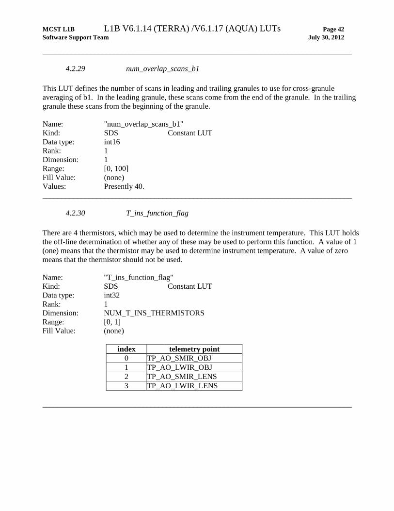
4.2.29 num_overlap_scans_b1 This LUT defines the number of scans in leading and trailing granules to use for cross-granule averaging of b1. In the leading granule, these scans come from the end of the granule. In the trailing granule these scans from the beginning of the granule. Name: "num_overlap_scans_b1" Kind: SDS Constant LUT Data type: int16 Rank: 1 Dimension: 1 Range: [0, 100] Fill Value: (none) Values: Presently 40. ________________________________________________________________________________
4.2.30 T_ins_function_flag There are 4 thermistors, which may be used to determine the instrument temperature. This LUT holds the off-line determination of whether any of these may be used to perform this function. A value of 1 (one) means that the thermistor may be used to determine instrument temperature. A value of zero means that the thermistor should not be used. Name: "T_ins_function_flag" Kind: SDS Constant LUT Data type: int32 Rank: 1 Dimension: NUM_T_INS_THERMISTORS Range: [0, 1] Fill Value: (none)
index telemetry point 0 TP_AO_SMIR_OBJ 1 TP_AO_LWIR_OBJ 2 TP_AO_SMIR_LENS 3 TP_AO_LWIR_LENS ________________________________________________________________________________
MCST L1B L1B V6.1.14 (TERRA) /V6.1.17 (AQUA) LUTs Page 43 Software Support Team July 30, 2012
________________________________________________________________________________
4.2.31 T_ins_default This LUT holds the default value of instrument temperature in Kelvins to use if, on any scan, none of the four thermistors (described above in the T_ins_function_flag LUT, Section 4.2.30) was found suitable for providing the on line instrument temperature. Name: "T_ins_default" Kind: SDS Constant LUT Data type: Float32 Rank: 1 Dimension: 1 Range: [200., 300.] Fill Value: (none) ________________________________________________________________________________
4.2.32 T_ins_offset This LUT holds the thermistor-dependent offset value of instrument temperature in Kelvins to in the equation for computing the instrument temperature. These offsets are determined off-line. Name: "T_ins_offset" Kind: SDS Constant LUT Data type: float32 Rank: 1 Dimension: NUM_T_INS_THERMISTORS Range: [-15., 15.] Fill Value: (none)
index telemetry point 0 TP_AO_SMIR_OBJ 1 TP_AO_LWIR_OBJ 2 TP_AO_SMIR_LENS 3 TP_AO_LWIR_LENS ________________________________________________________________________________
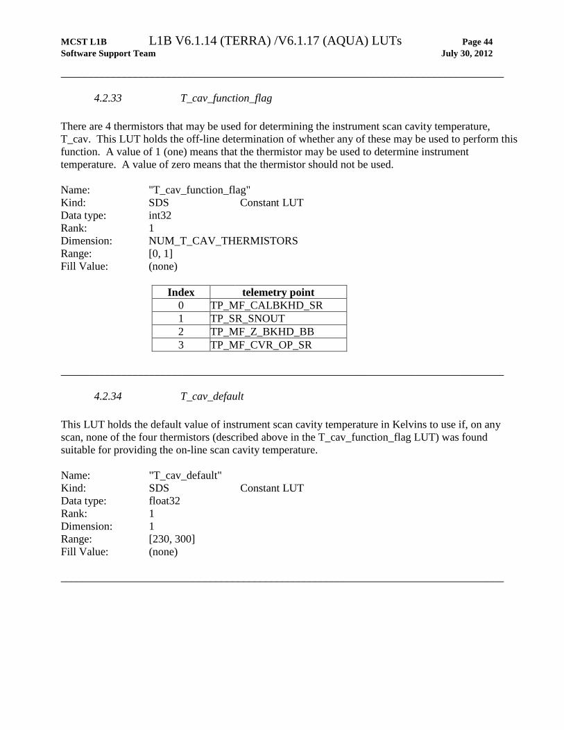
MCST L1B L1B V6.1.14 (TERRA) /V6.1.17 (AQUA) LUTs Page 44 Software Support Team July 30, 2012
________________________________________________________________________________
4.2.33 T_cav_function_flag There are 4 thermistors that may be used for determining the instrument scan cavity temperature, T_cav. This LUT holds the off-line determination of whether any of these may be used to perform this function. A value of 1 (one) means that the thermistor may be used to determine instrument temperature. A value of zero means that the thermistor should not be used. Name: "T_cav_function_flag" Kind: SDS Constant LUT Data type: int32 Rank: 1 Dimension: NUM_T_CAV_THERMISTORS Range: [0, 1] Fill Value: (none)
Index telemetry point 0 TP_MF_CALBKHD_SR 1 TP_SR_SNOUT 2 TP_MF_Z_BKHD_BB 3 TP_MF_CVR_OP_SR ________________________________________________________________________________
4.2.34 T_cav_default This LUT holds the default value of instrument scan cavity temperature in Kelvins to use if, on any scan, none of the four thermistors (described above in the T_cav_function_flag LUT) was found suitable for providing the on-line scan cavity temperature. Name: "T_cav_default" Kind: SDS Constant LUT Data type: float32 Rank: 1 Dimension: 1 Range: [230, 300] Fill Value: (none) ________________________________________________________________________________

MCST L1B L1B V6.1.14 (TERRA) /V6.1.17 (AQUA) LUTs Page 45 Software Support Team July 30, 2012
________________________________________________________________________________
4.2.35 T_mir_function_flag There are 2 thermistors that may be used for determining the average mirror temperature, T_mir. This LUT holds the off-line determination of whether any of these may be used to perform this function. A value of 1 (one) means that the thermistor may be used to determine temperature. A value of zero means that the thermistor should not be used. Name: "T_mir_function_flag" Kind: SDS Constant LUT Data type: int32 Rank: 1 Dimension: NUM_T_MIR_THERMISTORS Range: [0, 1] Fill Value: (none)
Index telemetry point 0 TP_SA_RCT1_MIRE 1 TP_SA_RCT2_MIRE ________________________________________________________________________________
4.2.36 T_mir_default This LUT holds the default value of average mirror temperature in Kelvins to use if, on any scan, neither of the two mirror thermistors (described above) was found suitable for providing the on-line scan average mirror temperature. Name: "T_mir_default" Kind: SDS Constant LUT Data type: float32 Rank: 1 Dimension: 1 Range: [230, 300] Fill Value: (none) ________________________________________________________________________________

MCST L1B L1B V6.1.14 (TERRA) /V6.1.17 (AQUA) LUTs Page 46 Software Support Team July 30, 2012
________________________________________________________________________________
4.2.37 BB_Weight There are 12 blackbody (BB) thermistors that may be used for determining the average blackbody temperature. This LUT holds a weighting factor to be applied in computing the average. This array should only be populated with 1's and 0's. Name: "BB_Weight" Kind: SDS Constant LUT Data type: float32 Rank: 1 Dimension: NUM_BB_THERMISTORS Range: [0, 1] Fill Value: (none) ________________________________________________________________________________
4.2.38 RVS_TEB This LUT holds the 2nd order polynomial coefficients used to compute the response vs. scan angle (RVS) as a function of frame number for the emissive bands. Polynomial evaluation will result in a normalized value of 1.0 at the center frame of the Solar diffuser sector (approximately 50.25 degrees). Name: "RVS_TEB" Kind: SDS Piecewise Linear LUT Data type: float32 Intrinsic Rank: 4 Dimensions: dim1: NUM_EMISSIVE_BANDS dim2: DETECTORS_PER_1KM_BAND dim3: NUM_MIRROR_SIDES dim4: NUM_2ND_ORDER_COEFFS Range: [-2.0E-4, 1.2] Fill Value: -999 ________________________________________________________________________________
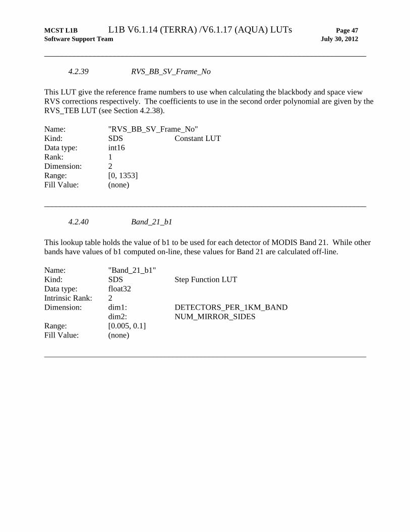
MCST L1B L1B V6.1.14 (TERRA) /V6.1.17 (AQUA) LUTs Page 47 Software Support Team July 30, 2012
________________________________________________________________________________
4.2.39 RVS_BB_SV_Frame_No This LUT give the reference frame numbers to use when calculating the blackbody and space view RVS corrections respectively. The coefficients to use in the second order polynomial are given by the RVS_TEB LUT (see Section 4.2.38). Name: "RVS_BB_SV_Frame_No" Kind: SDS Constant LUT Data type: int16 Rank: 1 Dimension: 2 Range: [0, 1353] Fill Value: (none) ________________________________________________________________________________
4.2.40 Band_21_b1 This lookup table holds the value of b1 to be used for each detector of MODIS Band 21. While other bands have values of b1 computed on-line, these values for Band 21 are calculated off-line. Name: "Band_21_b1" Kind: SDS Step Function LUT Data type: float32 Intrinsic Rank: 2 Dimension: dim1: DETECTORS_PER_1KM_BAND dim2: NUM_MIRROR_SIDES Range: [0.005, 0.1] Fill Value: (none) ________________________________________________________________________________

MCST L1B L1B V6.1.14 (TERRA) /V6.1.17 (AQUA) LUTs Page 48 Software Support Team July 30, 2012
________________________________________________________________________________
4.2.41 L_Max In the Level 1B code, a calibrated radiance in the range of [L_Min, L_Max] is scaled to an integer in the range of [0, 32767]. This LUT contains L_Max, the upper limit of the dynamic range, for each of the thermal emissive bands. Units are watts/m2/µm/steradians. Name: "L_Max" Kind: SDS Constant LUT Data type: float32 Rank: 1 Dimension: NUM_EMISSIVE_BANDS Range: [0, 110] (MODIS/AQUA)
[0, 100] (MODIS/TERRA)
Fill Value: (none) ________________________________________________________________________________
4.2.42 L_Min In the Level 1B code, a calibrated radiance in the range of [L_Min, L_Max] is scaled to an integer in the range of [0, 32767]. This LUT contains L_Min, the lower limit of the dynamic range, for each of the thermal emissive bands. Units are watts/m2/µm/steradians. Name: "L_Min" Kind: SDS Constant LUT Data type: float32 Rank: 1 Dimension: NUM_EMISSIVE_BANDS Range: [-10., 0] Fill Value: (none) ________________________________________________________________________________

MCST L1B L1B V6.1.14 (TERRA) /V6.1.17 (AQUA) LUTs Page 49 Software Support Team July 30, 2012
________________________________________________________________________________
4.2.43 TEB_specified_uncertainty This LUT contains the specified uncertainty factor for each thermal emissive band which is used (along with the scaling factor described by the LUT "TEB_scaling_factor") to convert percent uncertainty to an uncertainty index. The formula for uncertainty index (UI) in terms of uncertainty_in_percent, specified_uncertainty and scaling_factor is: UI = scaling_factor * ln (uncertainty_in_percent / specified_uncertainty) where "ln" is the natural logarithm. The uncertainty in percent is computed dynamically within the Level 1B code. Name: "TEB_specified_uncertainty" Kind: SDS Constant LUT Data type: float32 Rank: 1 Dimension: NUM_EMISSIVE_BANDS Range: N/A Fill Value: (none) ________________________________________________________________________________
4.2.44 TEB_UI_scaling_factor This LUT contains the scaling factor for each thermal emissive band for computing the uncertainty index from uncertainty in percent. (see comments above for "TEB_specified_uncertainty", Section 4.2.43). Name: "TEB_UI_scaling_factor" Kind: SDS Constant LUT Data type: float32 Rank: 1 Dimension: NUM_EMISSIVE_BANDS Range: N/A Fill Value: (none) ________________________________________________________________________________
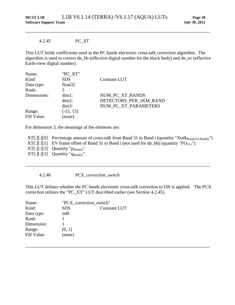
MCST L1B L1B V6.1.14 (TERRA) /V6.1.17 (AQUA) LUTs Page 50 Software Support Team July 30, 2012
________________________________________________________________________________
4.2.45 PC_XT This LUT holds coefficients used in the PC bands electronic cross-talk correction algorithm. The algorithm is used to correct dn_bb (effective digital number for the black body) and dn_ev (effective Earth-view digital number). Name: "PC_XT" Kind: SDS Constant LUT Data type: float32 Rank: 3 Dimensions: dim1: NUM_PC_XT_BANDS dim2: DETECTORS_PER_1KM_BAND dim3: NUM_PC_XT_PARAMETERS Range: [-15, 15] Fill Value: (none) For dimension 3, the meanings of the elements are: XT[:][:][0] Percentage amount of cross-talk from Band 31 to Band i (quantity "XtalkBand(31)-Band(i)") XT[:][:][1] EV frame offset of Band 31 to Band i (not used for dn_bb) (quantity "FO31-i"). XT[:][:][2] Quantity "pBand(i)". XT[:][:][3] Quantity "qBand(i)".
________________________________________________________________________________
4.2.46 PCX_correction_switch This LUT defines whether the PC bands electronic cross-talk correction to DN is applied. The PCX correction utilizes the "PC_XT" LUT described earlier (see Section 4.2.45). Name: "PCX_correction_switch" Kind: SDS Constant LUT Data type: int8 Rank: 1 Dimension: 1 Range: [0, 1] Fill Value: (none) ________________________________________________________________________________

MCST L1B L1B V6.1.14 (TERRA) /V6.1.17 (AQUA) LUTs Page 51 Software Support Team July 30, 2012
________________________________________________________________________________
4.2.47 BB_T_sat_default_b1_c1_aqua (MODIS/AQUA only) This LUT contains the b1 vs T_lwir rate (c1). The relationship between b1 and T_lwir is assumed to be linear. The b1 vs T_lwir rate is calculated from three-orbit OBC granules acquired before each WUCD cycle. Name: "BB_T_sat_default_b1_c1_aqua" Kind: SDS Step Function LUT Data type: float32 Rank: 3 Dimensions: dim1: NUM_AQUA_BB_SAT_BANDS dim2: DETECTORS_PER_1KM_BAND dim3: NUM_MIRROR_SIDES Range: N/A Fill Value: (none) ________________________________________________________________________________
4.2.48 BB_T_sat_default_b1_Tlwir_baseline_aqua (MODIS/AQUA only) This LUT contains T_lwir baseline which is currently set as 83K. Name: “BB_T_sat_default_b1_Tlwir_baseline_aqua” Kind: SDS Constant LUT Data type: float32 Rank: 1 Dimension: LWIR FPA Temperature Range: N/A Fill Value: (none) ________________________________________________________________________________

MCST L1B L1B V6.1.14 (TERRA) /V6.1.17 (AQUA) LUTs Page 52 Software Support Team July 30, 2012
________________________________________________________________________________
4.2.49 BB_T_sat_default_b1_baseline_aqua (MODIS/AQUA only) For use with MODIS/Aqua data only. For each emissive band/detector combination affected, this LUT gives a default b1 value. The new default b1 value depends on T_lwir, which oscillates on an orbital basis. The revised approach provides a more accurate b1 value for detectors in bands affected by the loss of cooler margin in the LWIR focal plane. Name: "BB_T_sat_default_b1_baseline_aqua” Kind: SDS Step Function LUT Data type: float32 Rank: 3 Dimensions: dim1: NUM_AQUA_BB_SAT_BANDS dim2: DETECTORS_PER_1KM_BAND dim3: NUM_MIRROR_SIDES Range: N/A Fill Value: (none) ________________________________________________________________________________
4.2.50 BB_T_sat_switch_aqua (MODIS/AQUA only) For use with MODIS/Aqua data only. Determines whether or not the default b1 value is used. Name: "BB_T_sat_switch" Kind: SDS constant Data type: int8 Rank: 1 Dimension: 1 Range: [0, 1] Fill Value: (none) ________________________________________________________________________________
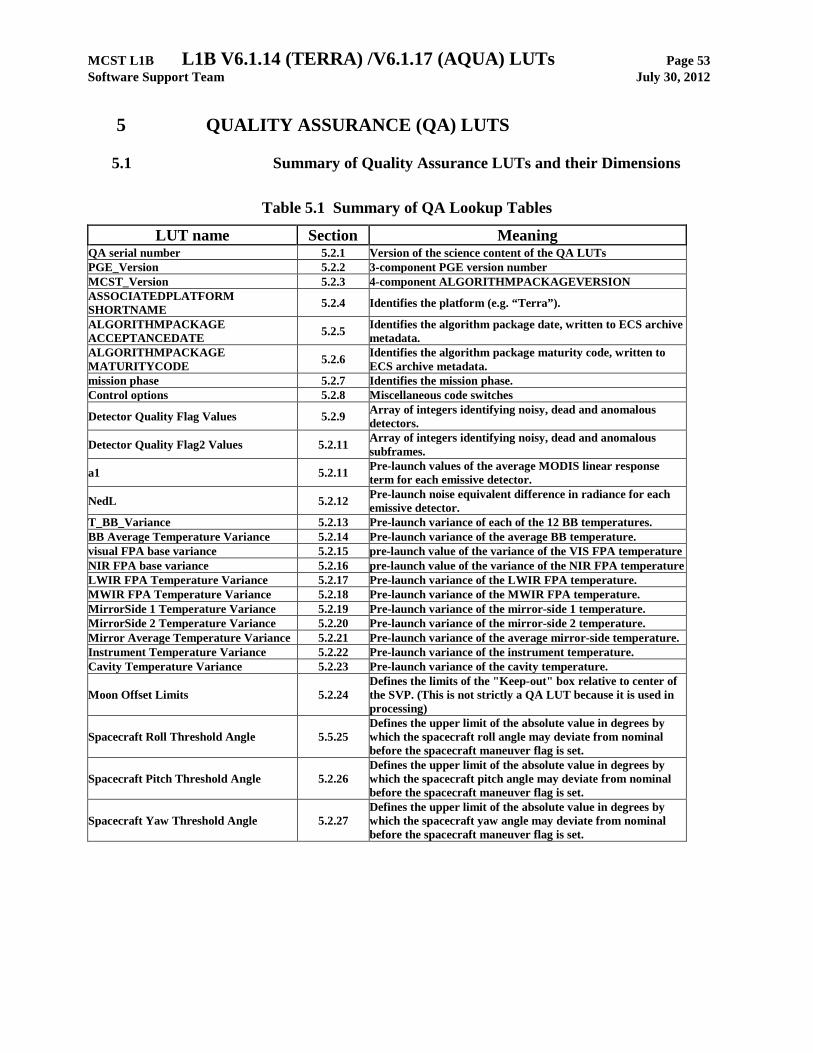
MCST L1B L1B V6.1.14 (TERRA) /V6.1.17 (AQUA) LUTs Page 53 Software Support Team July 30, 2012
5 QUALITY ASSURANCE (QA) LUTS
5.1 Summary of Quality Assurance LUTs and their Dimensions
Table 5.1 Summary of QA Lookup Tables
LUT name Section Meaning QA serial number 5.2.1 Version of the science content of the QA LUTs PGE_Version 5.2.2 3-component PGE version number MCST_Version 5.2.3 4-component ALGORITHMPACKAGEVERSION ASSOCIATEDPLATFORM SHORTNAME 5.2.4 Identifies the platform (e.g. “Terra”).
ALGORITHMPACKAGE ACCEPTANCEDATE 5.2.5 Identifies the algorithm package date, written to ECS archive
metadata.
ALGORITHMPACKAGE MATURITYCODE 5.2.6 Identifies the algorithm package maturity code, written to
ECS archive metadata.
mission phase 5.2.7 Identifies the mission phase. Control options 5.2.8 Miscellaneous code switches
Detector Quality Flag Values 5.2.9 Array of integers identifying noisy, dead and anomalous detectors.
Detector Quality Flag2 Values 5.2.11 Array of integers identifying noisy, dead and anomalous subframes.
a1 5.2.11 Pre-launch values of the average MODIS linear response term for each emissive detector.
NedL 5.2.12 Pre-launch noise equivalent difference in radiance for each emissive detector.
T_BB_Variance 5.2.13 Pre-launch variance of each of the 12 BB temperatures. BB Average Temperature Variance 5.2.14 Pre-launch variance of the average BB temperature. visual FPA base variance 5.2.15 pre-launch value of the variance of the VIS FPA temperature NIR FPA base variance 5.2.16 pre-launch value of the variance of the NIR FPA temperature LWIR FPA Temperature Variance 5.2.17 Pre-launch variance of the LWIR FPA temperature. MWIR FPA Temperature Variance 5.2.18 Pre-launch variance of the MWIR FPA temperature. MirrorSide 1 Temperature Variance 5.2.19 Pre-launch variance of the mirror-side 1 temperature. MirrorSide 2 Temperature Variance 5.2.20 Pre-launch variance of the mirror-side 2 temperature. Mirror Average Temperature Variance 5.2.21 Pre-launch variance of the average mirror-side temperature. Instrument Temperature Variance 5.2.22 Pre-launch variance of the instrument temperature. Cavity Temperature Variance 5.2.23 Pre-launch variance of the cavity temperature.
Moon Offset Limits 5.2.24 Defines the limits of the "Keep-out" box relative to center of the SVP. (This is not strictly a QA LUT because it is used in processing)
Spacecraft Roll Threshold Angle 5.5.25 Defines the upper limit of the absolute value in degrees by which the spacecraft roll angle may deviate from nominal before the spacecraft maneuver flag is set.
Spacecraft Pitch Threshold Angle 5.2.26 Defines the upper limit of the absolute value in degrees by which the spacecraft pitch angle may deviate from nominal before the spacecraft maneuver flag is set.
Spacecraft Yaw Threshold Angle 5.2.27 Defines the upper limit of the absolute value in degrees by which the spacecraft yaw angle may deviate from nominal before the spacecraft maneuver flag is set.

MCST L1B L1B V6.1.14 (TERRA) /V6.1.17 (AQUA) LUTs Page 54 Software Support Team July 30, 2012
Table 5.2 Dimensions used in QA LUTs
Dimension macro value meaning MAX_ALGORITHMPACKAGEACCEPTANCEDATE_BUFFER 11 Largest allowable string length MAX_ALGORITHMPACKAGEMATURITYCODE_BUFFER 11 Largest allowable string length MAX_ASSOCIATEDPLATFORMSHORTNAME_BUFFER 21 Largest allowable string length MAX_MCST_VERSION_BUFFER 21 Largest allowable string length MAX_MISSION_PHASE_BUFFER 11 Largest allowable string length MAX_PGE_VERSION_BUFFER 11 Largest allowable string length MAX_SERIAL_NUMBER_BUFFER 31 Largest allowable string length NUM_BANDS 38 Number of MODIS Bands NUM_BB_THERMISTORS 12 Number of blackbody thermistors NUM_BITS_IN_UINT8 8 Number of bits in unsigned integer NUM_CONTROL_OPTIONS 2 Number of control options NUM_DETECTORS 490 Number of MODIS detectors
NUM_HIGH_RESOLUTION_DETECTORS 180 Number of MODIS high resolution detectors
NUM_EMISSIVE_DETECTORS 160 Number of MODIS Emissive band detectors
NUM_MOON_OFFSET_LIMITS 4 Number of moon offset limits
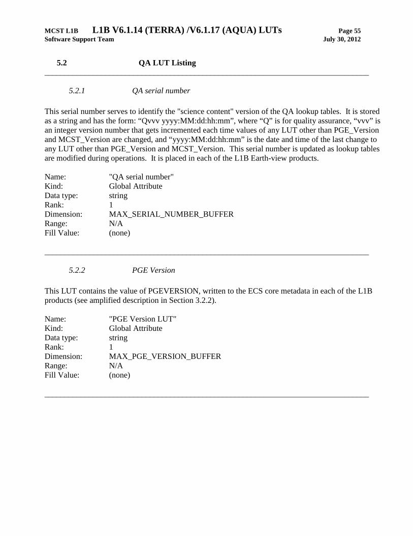
MCST L1B L1B V6.1.14 (TERRA) /V6.1.17 (AQUA) LUTs Page 55 Software Support Team July 30, 2012
5.2 QA LUT Listing
________________________________________________________________________________
5.2.1 QA serial number This serial number serves to identify the "science content" version of the QA lookup tables. It is stored as a string and has the form: “Qvvv yyyy:MM:dd:hh:mm”, where “Q” is for quality assurance, “vvv” is an integer version number that gets incremented each time values of any LUT other than PGE_Version and MCST_Version are changed, and “yyyy:MM:dd:hh:mm” is the date and time of the last change to any LUT other than PGE_Version and MCST_Version. This serial number is updated as lookup tables are modified during operations. It is placed in each of the L1B Earth-view products. Name: "QA serial number" Kind: Global Attribute Data type: string Rank: 1 Dimension: MAX_SERIAL_NUMBER_BUFFER Range: N/A Fill Value: (none) ________________________________________________________________________________
5.2.2 PGE Version This LUT contains the value of PGEVERSION, written to the ECS core metadata in each of the L1B products (see amplified description in Section 3.2.2). Name: "PGE Version LUT" Kind: Global Attribute Data type: string Rank: 1 Dimension: MAX_PGE_VERSION_BUFFER Range: N/A Fill Value: (none) ________________________________________________________________________________
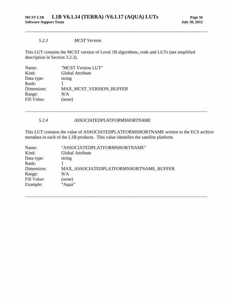
MCST L1B L1B V6.1.14 (TERRA) /V6.1.17 (AQUA) LUTs Page 56 Software Support Team July 30, 2012
________________________________________________________________________________
5.2.3 MCST Version This LUT contains the MCST version of Level 1B algorithms, code and LUTs (see amplified description in Section 3.2.3). Name: "MCST Version LUT" Kind: Global Attribute Data type: string Rank: 1 Dimension: MAX_MCST_VERSION_BUFFER Range: N/A Fill Value: (none) ________________________________________________________________________________
5.2.4 ASSOCIATEDPLATFORMSHORTNAME This LUT contains the value of ASSOCIATEDPLATFORMSHORTNAME written to the ECS archive metadata in each of the L1B products. This value identifies the satellite platform. Name: "ASSOCIATEDPLATFORMSHORTNAME" Kind: Global Attribute Data type: string Rank: 1 Dimension: MAX_ASSOCIATEDPLATFORMSHORTNAME_BUFFER Range: N/A Fill Value: (none) Example: “Aqua” ________________________________________________________________________________
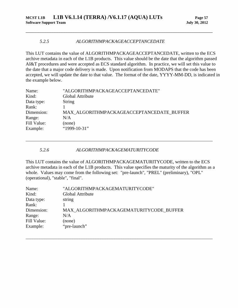
MCST L1B L1B V6.1.14 (TERRA) /V6.1.17 (AQUA) LUTs Page 57 Software Support Team July 30, 2012
________________________________________________________________________________
5.2.5 ALGORITHMPACKAGEACCEPTANCEDATE This LUT contains the value of ALGORITHMPACKAGEACCEPTANCEDATE, written to the ECS archive metadata in each of the L1B products. This value should be the date that the algorithm passed AI&T procedures and were accepted as ECS standard algorithm. In practice, we will set this value to the date that a major code delivery is made. Upon notification from MODAPS that the code has been accepted, we will update the date to that value. The format of the date, YYYY-MM-DD, is indicated in the example below. Name: "ALGORITHMPACKAGEACCEPTANCEDATE" Kind: Global Attribute Data type: String Rank: 1 Dimension: MAX_ALGORITHMPACKAGEACCEPTANCEDATE_BUFFER Range: N/A Fill Value: (none) Example: “1999-10-31” ________________________________________________________________________________
5.2.6 ALGORITHMPACKAGEMATURITYCODE This LUT contains the value of ALGORITHMPACKAGEMATURITYCODE, written to the ECS archive metadata in each of the L1B products. This value specifies the maturity of the algorithm as a whole. Values may come from the following set: "pre-launch", "PREL" (preliminary), "OPL" (operational), "stable", "final". Name: "ALGORITHMPACKAGEMATURITYCODE" Kind: Global Attribute Data type: string Rank: 1 Dimension: MAX_ALGORITHMPACKAGEMATURITYCODE_BUFFER Range: N/A Fill Value: (none) Example: “pre-launch” ________________________________________________________________________________

MCST L1B L1B V6.1.14 (TERRA) /V6.1.17 (AQUA) LUTs Page 58 Software Support Team July 30, 2012
________________________________________________________________________________
5.2.7 mission phase This LUT defines the current mission phase. Name: "mission phase" Kind: Global Attribute Data type: string Rank: 1 Dimension: MAX_MISSION_PHASE_BUFFER Range: N/A Fill Value: (none) Value: Set to “A&E” at launch, updated as necessary thereafter. ________________________________________________________________________________
5.2.8 Control options This LUT contains miscellaneous L1B control options. Currently, there are two: • Split scans — control whether or not to treat as missing if a split scan is detected. There are only
two values, ON or OFF. • Bad scan quality — control whether or not to treat as missing if an invalid value of Scan quality
array is detected. There are only two values, ON or OFF. Name: "Control options" Kind: SDS Constant LUT Data type: uint8 Rank: 1 Dimension: NUM_CONTROL_OPTIONS Range: [0, 1] Fill Value: (none) ________________________________________________________________________________

MCST L1B L1B V6.1.14 (TERRA) /V6.1.17 (AQUA) LUTs Page 59 Software Support Team July 30, 2012
________________________________________________________________________________
5.2.9 Detector Quality Flag Values This LUT contains the array used to fill the L1B global attribute "Detector Quality Flag". Each array element of this LUT (having a value of 0 or 1) sets one bit of the corresponding L1B attribute. The second dimension of this LUT cycles through the 8 bits of each word of the attribute, with array element [w][0] corresponding to the least significant bit on word w and array element [w][7] corresponding to the most significant bit. Name: "Detector Quality Flag Values" Kind: SDS Step Function LUT Data type: uint8 Intrinsic Rank: 2 Dimensions: dim1: NUM_DETECTORS dim2: NUM_BITS_IN_UINT8 Range: [0, 1] Fill Value: (none) The following table maps the meaning of the bits in the Detector Quality Flag to the array elements:
Detector Quality Flag bit (0-based)
LUT 2nd dimension array element index (0-based)
Meaning
bit 0 (LSB) 0 Noisy Detector bit 1 1 Dead Detector bit 2 2 Out-of-Family Gain bit 3 3 Dynamic Range bit 4 4 RSB: Detector DN saturates on illuminated, unscreened Solar
Diffuser TEB: Detector DN saturates on blackbody when TBB = 300 K
bit 5 5 High calibration fit residuals bit 6 6 Electrical Crosstalk bit 7 (MSB) 7 (TBD) ________________________________________________________________________________
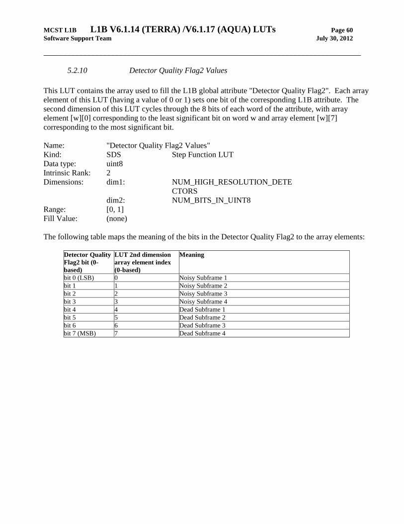
MCST L1B L1B V6.1.14 (TERRA) /V6.1.17 (AQUA) LUTs Page 60 Software Support Team July 30, 2012
________________________________________________________________________________
5.2.10 Detector Quality Flag2 Values This LUT contains the array used to fill the L1B global attribute "Detector Quality Flag2". Each array element of this LUT (having a value of 0 or 1) sets one bit of the corresponding L1B attribute. The second dimension of this LUT cycles through the 8 bits of each word of the attribute, with array element [w][0] corresponding to the least significant bit on word w and array element [w][7] corresponding to the most significant bit. Name: "Detector Quality Flag2 Values" Kind: SDS Step Function LUT Data type: uint8 Intrinsic Rank: 2 Dimensions: dim1: NUM_HIGH_RESOLUTION_DETE
CTORS
dim2: NUM_BITS_IN_UINT8 Range: [0, 1] Fill Value: (none) The following table maps the meaning of the bits in the Detector Quality Flag2 to the array elements:
Detector Quality Flag2 bit (0-based)
LUT 2nd dimension array element index (0-based)
Meaning
bit 0 (LSB) 0 Noisy Subframe 1 bit 1 1 Noisy Subframe 2 bit 2 2 Noisy Subframe 3 bit 3 3 Noisy Subframe 4 bit 4 4 Dead Subframe 1 bit 5 5 Dead Subframe 2 bit 6 6 Dead Subframe 3 bit 7 (MSB) 7 Dead Subframe 4
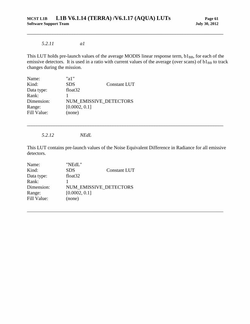
MCST L1B L1B V6.1.14 (TERRA) /V6.1.17 (AQUA) LUTs Page 61 Software Support Team July 30, 2012
________________________________________________________________________________
5.2.11 a1 This LUT holds pre-launch values of the average MODIS linear response term, b1BB, for each of the emissive detectors. It is used in a ratio with current values of the average (over scans) of b1BB to track changes during the mission. Name: "a1" Kind: SDS Constant LUT Data type: float32 Rank: 1 Dimension: NUM_EMISSIVE_DETECTORS Range: [0.0002, 0.1] Fill Value: (none) ________________________________________________________________________________
5.2.12 NEdL This LUT contains pre-launch values of the Noise Equivalent Difference in Radiance for all emissive detectors. Name: "NEdL" Kind: SDS Constant LUT Data type: float32 Rank: 1 Dimension: NUM_EMISSIVE_DETECTORS Range: [0.0002, 0.1] Fill Value: (none) ________________________________________________________________________________

MCST L1B L1B V6.1.14 (TERRA) /V6.1.17 (AQUA) LUTs Page 62 Software Support Team July 30, 2012
________________________________________________________________________________
5.2.13 T_BB_Variance This LUT holds pre-launch values of the variance of each of the 12 blackbody (BB) temperatures. The code forms the ratio of the current variances (across scans within the granule) with these values to track the change during the mission. Name: "T_BB_Variance" Kind: SDS Constant LUT Data type: float32 Rank: 1 Dimension: NUM_BB_THERMISTORS Range: [0.0002, 0.1] (MODIS/AQUA)
[0.001, 0.1] (MODIS/TERRA)
Fill Value: (none) ________________________________________________________________________________
5.2.14 BB Average Temperature Variance This LUT holds a pre-launch value of the variance of the average blackbody (BB) temperature. The code forms the ratio of the current variance (across scans within the granule) with this value to track the change during the mission. Name: "BB Average Temperature Variance" Kind: SDS Constant LUT Data type: float32 Rank: 1 Dimension: 1 Range: [0.00003, 0.1] (MODIS/AQUA)
[0.0001, 0.1] (MODIS/TERRA)
Fill Value: (none) ________________________________________________________________________________
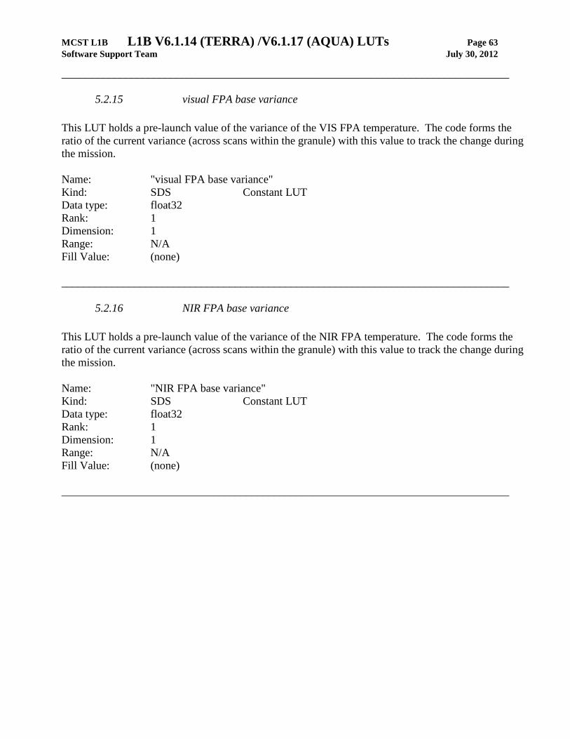
MCST L1B L1B V6.1.14 (TERRA) /V6.1.17 (AQUA) LUTs Page 63 Software Support Team July 30, 2012
________________________________________________________________________________
5.2.15 visual FPA base variance This LUT holds a pre-launch value of the variance of the VIS FPA temperature. The code forms the ratio of the current variance (across scans within the granule) with this value to track the change during the mission. Name: "visual FPA base variance" Kind: SDS Constant LUT Data type: float32 Rank: 1 Dimension: 1 Range: N/A Fill Value: (none) ________________________________________________________________________________
5.2.16 NIR FPA base variance This LUT holds a pre-launch value of the variance of the NIR FPA temperature. The code forms the ratio of the current variance (across scans within the granule) with this value to track the change during the mission. Name: "NIR FPA base variance" Kind: SDS Constant LUT Data type: float32 Rank: 1 Dimension: 1 Range: N/A Fill Value: (none) ________________________________________________________________________________
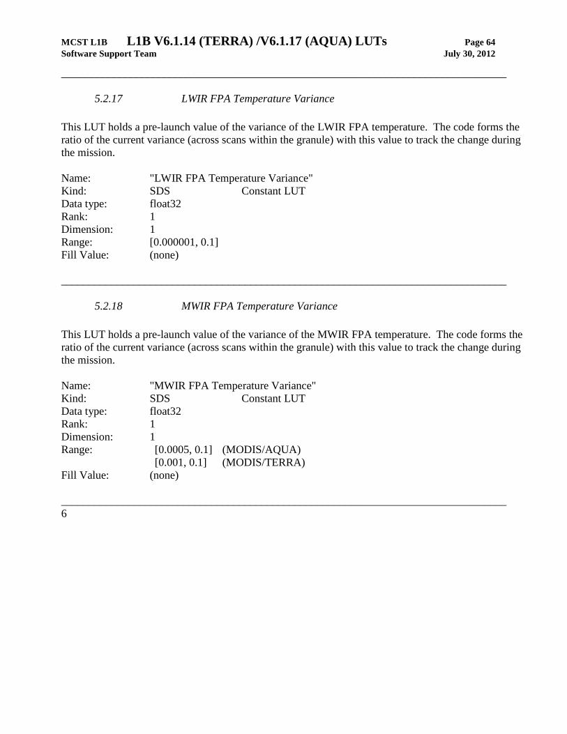
MCST L1B L1B V6.1.14 (TERRA) /V6.1.17 (AQUA) LUTs Page 64 Software Support Team July 30, 2012
________________________________________________________________________________
5.2.17 LWIR FPA Temperature Variance This LUT holds a pre-launch value of the variance of the LWIR FPA temperature. The code forms the ratio of the current variance (across scans within the granule) with this value to track the change during the mission. Name: "LWIR FPA Temperature Variance" Kind: SDS Constant LUT Data type: float32 Rank: 1 Dimension: 1 Range: [0.000001, 0.1] Fill Value: (none) ________________________________________________________________________________
5.2.18 MWIR FPA Temperature Variance This LUT holds a pre-launch value of the variance of the MWIR FPA temperature. The code forms the ratio of the current variance (across scans within the granule) with this value to track the change during the mission. Name: "MWIR FPA Temperature Variance" Kind: SDS Constant LUT Data type: float32 Rank: 1 Dimension: 1 Range: [0.0005, 0.1] (MODIS/AQUA)
[0.001, 0.1] (MODIS/TERRA)
Fill Value: (none) ________________________________________________________________________________6
MCST L1B L1B V6.1.14 (TERRA) /V6.1.17 (AQUA) LUTs Page 65 Software Support Team July 30, 2012
________________________________________________________________________________
5.2.19 MirrorSide 1 Temperature Variance This LUT holds a pre-launch value of the variance of the mirror (side 1) temperature. The code forms the ratio of the current variance (across scans within the granule) with this value to track the change during the mission. Name: "MirrorSide 1 Temperature Variance" Kind: SDS Constant LUT Data type: float32 Rank: 1 Dimension: 1 Range: [0.0001, 0.1] Fill Value: (none) ________________________________________________________________________________
5.2.20 MirrorSide 2 Temperature Variance This LUT holds a pre-launch value of the variance of the mirror (side 2) temperature. The code forms the ratio of the current variance (across scans within the granule) with this value to track the change during the mission. Name: "MirrorSide 2 Temperature Variance" Kind: SDS Constant LUT Data type: float32 Rank: 1 Dimension: 1 Range: [0.0001, 0.1] Fill Value: (none) ________________________________________________________________________________

MCST L1B L1B V6.1.14 (TERRA) /V6.1.17 (AQUA) LUTs Page 66 Software Support Team July 30, 2012
________________________________________________________________________________
5.2.21 Mirror Average Temperature Variance This LUT holds a pre-launch value of the variance of the average mirror temperature. The code forms the ratio of the current variance (across scans within the granule) with this value to track the change during the mission. Name: "Mirror Average Temperature Variance" Kind: SDS Constant LUT Data type: float32 Rank: 1 Dimension: 1 Range: [0.001, 0.1] Fill Value: (none) ________________________________________________________________________________
5.2.22 Instrument Temperature Variance This LUT holds a pre-launch value of the variance of the instrument temperature. The code forms the ratio of the current variance (across scans within the granule) with this value to track the change during the mission. Name: "Instrument Temperature Variance" Kind: SDS Constant LUT Data type: float32 Rank: 1 Dimension: 1 Range: [0.001, 0.1] Fill Value: (none) ________________________________________________________________________________
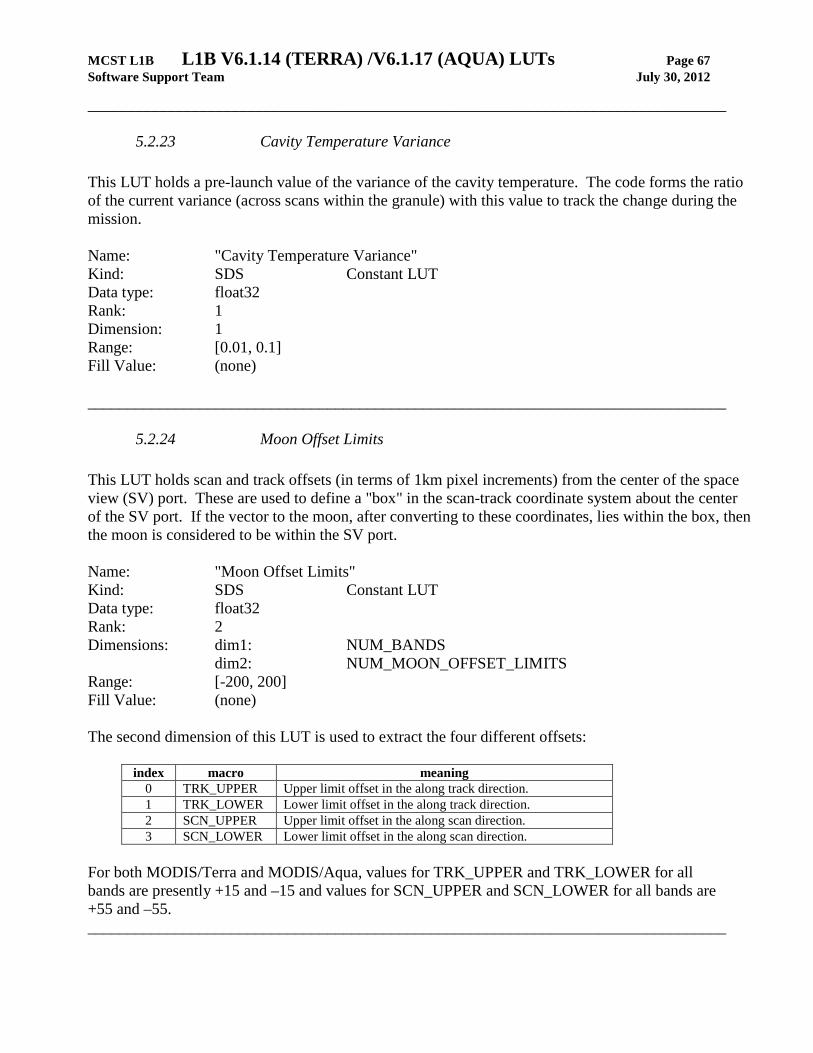
MCST L1B L1B V6.1.14 (TERRA) /V6.1.17 (AQUA) LUTs Page 67 Software Support Team July 30, 2012
________________________________________________________________________________
5.2.23 Cavity Temperature Variance This LUT holds a pre-launch value of the variance of the cavity temperature. The code forms the ratio of the current variance (across scans within the granule) with this value to track the change during the mission. Name: "Cavity Temperature Variance" Kind: SDS Constant LUT Data type: float32 Rank: 1 Dimension: 1 Range: [0.01, 0.1] Fill Value: (none) ________________________________________________________________________________
5.2.24 Moon Offset Limits This LUT holds scan and track offsets (in terms of 1km pixel increments) from the center of the space view (SV) port. These are used to define a "box" in the scan-track coordinate system about the center of the SV port. If the vector to the moon, after converting to these coordinates, lies within the box, then the moon is considered to be within the SV port. Name: "Moon Offset Limits" Kind: SDS Constant LUT Data type: float32 Rank: 2 Dimensions: dim1: NUM_BANDS dim2: NUM_MOON_OFFSET_LIMITS Range: [-200, 200] Fill Value: (none) The second dimension of this LUT is used to extract the four different offsets:
index macro meaning 0 TRK_UPPER Upper limit offset in the along track direction. 1 TRK_LOWER Lower limit offset in the along track direction. 2 SCN_UPPER Upper limit offset in the along scan direction. 3 SCN_LOWER Lower limit offset in the along scan direction.
For both MODIS/Terra and MODIS/Aqua, values for TRK_UPPER and TRK_LOWER for all bands are presently +15 and –15 and values for SCN_UPPER and SCN_LOWER for all bands are +55 and –55. ________________________________________________________________________________
MCST L1B L1B V6.1.14 (TERRA) /V6.1.17 (AQUA) LUTs Page 68 Software Support Team July 30, 2012
________________________________________________________________________________
5.2.25 Spacecraft Roll Threshold Angle This LUT defines the upper limit of the absolute deviation from nominal allowed in the spacecraft roll angle, measured in degrees. If the spacecraft deviates from nominal by more than this amount, the maneuver flag is set. Name: "Spacecraft_Roll_Threshold_Angle" Kind: SDS Constant LUT Data type: float32 Rank: 1 Dimension: 1 Range: [0.0, 360.0] Fill Value: (none) Value: Currently set to 1.0 ________________________________________________________________________________
5.2.26 Spacecraft Pitch Threshold Angle This LUT defines the upper limit of the absolute deviation from nominal allowed in the spacecraft pitch angle, measured in degrees. If the spacecraft deviates from nominal by more than this amount, the maneuver flag is set. Name: "Spacecraft_Pitch_Threshold_Angle" Kind: SDS Constant LUT Data type: float32 Rank: 1 Dimension: 1 Range: [0.0, 360.0] Fill Value: (none) Value: Currently set to 1.0 ________________________________________________________________________________

MCST L1B L1B V6.1.14 (TERRA) /V6.1.17 (AQUA) LUTs Page 69 Software Support Team July 30, 2012
________________________________________________________________________________
5.2.27 Spacecraft Yaw Threshold Angle This LUT defines the upper limit of the absolute deviation from nominal allowed in the spacecraft yaw angle, measured in degrees. If the spacecraft deviates from nominal by more than this amount, the maneuver flag is set. Name: "Spacecraft_Yaw_Threshold_Angle" Kind: SDS Constant LUT Data type: float32 Rank: 1 Dimension: 1 Range: [0.0, 360.0] Fill Value: (none) Value: Currently set to 1.0 ________________________________________________________________________________