modicon premium plcs
TRANSCRIPT

Modicon Premium PLCsTSX 57/PCX 57CommunicationNetwork and Bus InterfacesInstallation manual Volume 4
3500
9581
_02
May 2007eng

2 335009581 02 May 2007
Document Set
Document Set
At a Glance This documentation is made up of 5 Volumes:Volume 1
Racks/Supplies/ProcessorsImplementation/Diagnostics/MaintenanceStandards and operating conditionsProcess supply
Volume 2Discrete interfacesSafety
Volume 3CountingMotion control
Volume 4CommunicationNetwork and bus interfaces
Volume 5AnalogWeighing
335009581 02 May 2007 3

Document Set
4 335009581 02 May 2007
Table of Contents
About the Book . . . . . . . . . . . . . . . . . . . . . . . . . . . . . . . . . . . . . .13
Part I Terminal Port Communication . . . . . . . . . . . . . . . . . . . . 15At a Glance . . . . . . . . . . . . . . . . . . . . . . . . . . . . . . . . . . . . . . . . . . . . . . . . . . . . . 15
Chapter 1 Terminal Port. . . . . . . . . . . . . . . . . . . . . . . . . . . . . . . . . . . . . . . .17At a Glance . . . . . . . . . . . . . . . . . . . . . . . . . . . . . . . . . . . . . . . . . . . . . . . . . . . . . 17
1.1 Introduction to the terminal port. . . . . . . . . . . . . . . . . . . . . . . . . . . . . . . . . . . . . . 18At a Glance . . . . . . . . . . . . . . . . . . . . . . . . . . . . . . . . . . . . . . . . . . . . . . . . . . . . . 18Introduction to the terminal port. . . . . . . . . . . . . . . . . . . . . . . . . . . . . . . . . . . . . . 19Communication with a programming/adjustment terminal . . . . . . . . . . . . . . . . . 21Communicating with a man-machine interface console . . . . . . . . . . . . . . . . . . . 22UNI-TELWAY master/slave communication . . . . . . . . . . . . . . . . . . . . . . . . . . . . 24Character string communication . . . . . . . . . . . . . . . . . . . . . . . . . . . . . . . . . . . . . 25
1.2 Connections . . . . . . . . . . . . . . . . . . . . . . . . . . . . . . . . . . . . . . . . . . . . . . . . . . . . 26At a Glance . . . . . . . . . . . . . . . . . . . . . . . . . . . . . . . . . . . . . . . . . . . . . . . . . . . . . 26Connections . . . . . . . . . . . . . . . . . . . . . . . . . . . . . . . . . . . . . . . . . . . . . . . . . . . . 27Programming/adjustment terminal . . . . . . . . . . . . . . . . . . . . . . . . . . . . . . . . . . . 28Man-machine interface console . . . . . . . . . . . . . . . . . . . . . . . . . . . . . . . . . . . . . 30Programming/adjustment terminal and man-machine interface console . . . . . . 31Modem on terminal port . . . . . . . . . . . . . . . . . . . . . . . . . . . . . . . . . . . . . . . . . . . 32Master UNI-TELWAY . . . . . . . . . . . . . . . . . . . . . . . . . . . . . . . . . . . . . . . . . . . . . 34Slave UNI-TELWAY . . . . . . . . . . . . . . . . . . . . . . . . . . . . . . . . . . . . . . . . . . . . . . 35UNI-TELWAY inter-PLC link . . . . . . . . . . . . . . . . . . . . . . . . . . . . . . . . . . . . . . . . 36Inter-device UNI-TELWAY . . . . . . . . . . . . . . . . . . . . . . . . . . . . . . . . . . . . . . . . . 38 Type TSX, model 40 master PLC. . . . . . . . . . . . . . . . . . . . . . . . . . . . . . . . . . . . 39Character string. . . . . . . . . . . . . . . . . . . . . . . . . . . . . . . . . . . . . . . . . . . . . . . . . . 40Summary table of terminal port connections . . . . . . . . . . . . . . . . . . . . . . . . . . . . 43
1.3 Appendices . . . . . . . . . . . . . . . . . . . . . . . . . . . . . . . . . . . . . . . . . . . . . . . . . . . . . 47At a Glance . . . . . . . . . . . . . . . . . . . . . . . . . . . . . . . . . . . . . . . . . . . . . . . . . . . . . 47Characteristics of the terminal port . . . . . . . . . . . . . . . . . . . . . . . . . . . . . . . . . . . 48Terminal port connector pin configuration . . . . . . . . . . . . . . . . . . . . . . . . . . . . . . 50
Chapter 2 TSX P ACC 01 device . . . . . . . . . . . . . . . . . . . . . . . . . . . . . . . .51At a Glance . . . . . . . . . . . . . . . . . . . . . . . . . . . . . . . . . . . . . . . . . . . . . . . . . . . . . 51
335009581 02 May 2007 5

2.1 At a Glance . . . . . . . . . . . . . . . . . . . . . . . . . . . . . . . . . . . . . . . . . . . . . . . . . . . . . 52At a Glance . . . . . . . . . . . . . . . . . . . . . . . . . . . . . . . . . . . . . . . . . . . . . . . . . . . . . 52Functionalities . . . . . . . . . . . . . . . . . . . . . . . . . . . . . . . . . . . . . . . . . . . . . . . . . . . 53External appearance . . . . . . . . . . . . . . . . . . . . . . . . . . . . . . . . . . . . . . . . . . . . . . 54
2.2 Hardware installation . . . . . . . . . . . . . . . . . . . . . . . . . . . . . . . . . . . . . . . . . . . . . . 55At a Glance . . . . . . . . . . . . . . . . . . . . . . . . . . . . . . . . . . . . . . . . . . . . . . . . . . . . . 55Dimensions and mounting . . . . . . . . . . . . . . . . . . . . . . . . . . . . . . . . . . . . . . . . . . 56Internal view. . . . . . . . . . . . . . . . . . . . . . . . . . . . . . . . . . . . . . . . . . . . . . . . . . . . . 57Connection to Uni-Telway Buses. . . . . . . . . . . . . . . . . . . . . . . . . . . . . . . . . . . . . 58Connecting to Premium and Atrium PLCs . . . . . . . . . . . . . . . . . . . . . . . . . . . . . . 59Switch configuration. . . . . . . . . . . . . . . . . . . . . . . . . . . . . . . . . . . . . . . . . . . . . . . 60TSX P ACC 01 connector pin configuration. . . . . . . . . . . . . . . . . . . . . . . . . . . . . 61
2.3 Example of topologies . . . . . . . . . . . . . . . . . . . . . . . . . . . . . . . . . . . . . . . . . . . . . 62At a Glance . . . . . . . . . . . . . . . . . . . . . . . . . . . . . . . . . . . . . . . . . . . . . . . . . . . . . 62Connectable devices . . . . . . . . . . . . . . . . . . . . . . . . . . . . . . . . . . . . . . . . . . . . . . 63UNI-TELWAY master mode. . . . . . . . . . . . . . . . . . . . . . . . . . . . . . . . . . . . . . . . . 65UNI-TELWAY slave mode . . . . . . . . . . . . . . . . . . . . . . . . . . . . . . . . . . . . . . . . . . 67Connection between two PLCs . . . . . . . . . . . . . . . . . . . . . . . . . . . . . . . . . . . . . . 68
Part II Processor-integrated master FIPIO communication . . .69At a Glance . . . . . . . . . . . . . . . . . . . . . . . . . . . . . . . . . . . . . . . . . . . . . . . . . . . . . 69
Chapter 3 Processor-integrated master FIPIO communication . . . . . . . 71At a Glance . . . . . . . . . . . . . . . . . . . . . . . . . . . . . . . . . . . . . . . . . . . . . . . . . . . . . 71Review of the FIPIO bus . . . . . . . . . . . . . . . . . . . . . . . . . . . . . . . . . . . . . . . . . . . 72Integrated FIPIO link on Premium/Atrium processors . . . . . . . . . . . . . . . . . . . . . 74Examples of architecture . . . . . . . . . . . . . . . . . . . . . . . . . . . . . . . . . . . . . . . . . . . 75
Part III AS-i bus interface: TSX SAY 100 module . . . . . . . . . . . .77At a Glance . . . . . . . . . . . . . . . . . . . . . . . . . . . . . . . . . . . . . . . . . . . . . . . . . . . . . 77
Chapter 4 AS-i bus interface module: TSX SAY 100 . . . . . . . . . . . . . . . . 79At a Glance . . . . . . . . . . . . . . . . . . . . . . . . . . . . . . . . . . . . . . . . . . . . . . . . . . . . . 79
4.1 Review of the AS-i bus. . . . . . . . . . . . . . . . . . . . . . . . . . . . . . . . . . . . . . . . . . . . . 80At a Glance . . . . . . . . . . . . . . . . . . . . . . . . . . . . . . . . . . . . . . . . . . . . . . . . . . . . . 80Review of the AS-i bus. . . . . . . . . . . . . . . . . . . . . . . . . . . . . . . . . . . . . . . . . . . . . 81Overview of AS-i products from the Schneider catalog . . . . . . . . . . . . . . . . . . . . 82Introduction to the main constituent elements . . . . . . . . . . . . . . . . . . . . . . . . . . . 83Example of AS-i bus topology . . . . . . . . . . . . . . . . . . . . . . . . . . . . . . . . . . . . . . . 87Main characteristics of the AS-i bus. . . . . . . . . . . . . . . . . . . . . . . . . . . . . . . . . . . 88
4.2 Description of the TSX SAY 100 module . . . . . . . . . . . . . . . . . . . . . . . . . . . . . . . 90At a Glance . . . . . . . . . . . . . . . . . . . . . . . . . . . . . . . . . . . . . . . . . . . . . . . . . . . . . 90Physical presentation. . . . . . . . . . . . . . . . . . . . . . . . . . . . . . . . . . . . . . . . . . . . . . 91Mounting/installation . . . . . . . . . . . . . . . . . . . . . . . . . . . . . . . . . . . . . . . . . . . . . . 92Connections . . . . . . . . . . . . . . . . . . . . . . . . . . . . . . . . . . . . . . . . . . . . . . . . . . . . . 93
6 335009581 02 May 2007

Displaying module states . . . . . . . . . . . . . . . . . . . . . . . . . . . . . . . . . . . . . . . . . . 97Specific Display Panels on the TSX SAY 100 Module . . . . . . . . . . . . . . . . . . . . 98Technical characteristics . . . . . . . . . . . . . . . . . . . . . . . . . . . . . . . . . . . . . . . . . . 100Personnel safety . . . . . . . . . . . . . . . . . . . . . . . . . . . . . . . . . . . . . . . . . . . . . . . . 101
4.3 Input/output object addressing . . . . . . . . . . . . . . . . . . . . . . . . . . . . . . . . . . . . . 102Addressing input/output objects . . . . . . . . . . . . . . . . . . . . . . . . . . . . . . . . . . . . 102
4.4 AS-i Bus diagnostics . . . . . . . . . . . . . . . . . . . . . . . . . . . . . . . . . . . . . . . . . . . . . 103At a Glance . . . . . . . . . . . . . . . . . . . . . . . . . . . . . . . . . . . . . . . . . . . . . . . . . . . . 103Introduction to AS-i Bus diagnostics . . . . . . . . . . . . . . . . . . . . . . . . . . . . . . . . . 104Moving between the different display modes . . . . . . . . . . . . . . . . . . . . . . . . . . 106Display of slaves on the AS-i bus . . . . . . . . . . . . . . . . . . . . . . . . . . . . . . . . . . . 107Viewing the state of input/output bits for each slave . . . . . . . . . . . . . . . . . . . . . 108
4.5 Operating modes of the TSX SAY 100 module. . . . . . . . . . . . . . . . . . . . . . . . . 110Operating modes of the TSX SAY 100 module. . . . . . . . . . . . . . . . . . . . . . . . . 110
4.6 Precautions of use. . . . . . . . . . . . . . . . . . . . . . . . . . . . . . . . . . . . . . . . . . . . . . . 112At a Glance . . . . . . . . . . . . . . . . . . . . . . . . . . . . . . . . . . . . . . . . . . . . . . . . . . . . 11224 V auxiliary supply . . . . . . . . . . . . . . . . . . . . . . . . . . . . . . . . . . . . . . . . . . . . . 113Multiple addressing . . . . . . . . . . . . . . . . . . . . . . . . . . . . . . . . . . . . . . . . . . . . . . 114
Part IV AS-i V2 bus interface: TSX SAY 1000 module . . . . . . . 115At a Glance . . . . . . . . . . . . . . . . . . . . . . . . . . . . . . . . . . . . . . . . . . . . . . . . . . . . 115
Chapter 5 AS-i V2 Bus Interface Module: TSX SAY 1000 . . . . . . . . . . . .117At a Glance . . . . . . . . . . . . . . . . . . . . . . . . . . . . . . . . . . . . . . . . . . . . . . . . . . . . 117
5.1 Introduction to the AS-i Bus. . . . . . . . . . . . . . . . . . . . . . . . . . . . . . . . . . . . . . . . 118At a Glance . . . . . . . . . . . . . . . . . . . . . . . . . . . . . . . . . . . . . . . . . . . . . . . . . . . . 118Introduction to the AS-i Bus. . . . . . . . . . . . . . . . . . . . . . . . . . . . . . . . . . . . . . . . 119Overview of AS-i Products from the Schneider Catalog . . . . . . . . . . . . . . . . . . 120Introduction to the Main Constituent Elements . . . . . . . . . . . . . . . . . . . . . . . . . 121Main Characteristics of the AS-i V2 Bus . . . . . . . . . . . . . . . . . . . . . . . . . . . . . . 122
5.2 Description of the TSX SAY 1000 Module . . . . . . . . . . . . . . . . . . . . . . . . . . . . 125At a Glance . . . . . . . . . . . . . . . . . . . . . . . . . . . . . . . . . . . . . . . . . . . . . . . . . . . . 125Physical Introduction . . . . . . . . . . . . . . . . . . . . . . . . . . . . . . . . . . . . . . . . . . . . . 126Mounting/Installation . . . . . . . . . . . . . . . . . . . . . . . . . . . . . . . . . . . . . . . . . . . . . 127Connections . . . . . . . . . . . . . . . . . . . . . . . . . . . . . . . . . . . . . . . . . . . . . . . . . . . 128Displaying Module States . . . . . . . . . . . . . . . . . . . . . . . . . . . . . . . . . . . . . . . . . 131Specific Display Panels on the TSX SAY 1000 Module . . . . . . . . . . . . . . . . . . 132Technical Characteristics of the AS-i V2 Bus . . . . . . . . . . . . . . . . . . . . . . . . . . 133Personnel Safety . . . . . . . . . . . . . . . . . . . . . . . . . . . . . . . . . . . . . . . . . . . . . . . . 134
5.3 Input/Output Object Addressing . . . . . . . . . . . . . . . . . . . . . . . . . . . . . . . . . . . . 135Addressing Input/Output Objects . . . . . . . . . . . . . . . . . . . . . . . . . . . . . . . . . . . 135
5.4 AS-i Bus Diagnostics. . . . . . . . . . . . . . . . . . . . . . . . . . . . . . . . . . . . . . . . . . . . . 137Introduction to AS-i Bus Diagnostics . . . . . . . . . . . . . . . . . . . . . . . . . . . . . . . . . 137
5.5 Operating Modes of the TSX SAY 1000 Module. . . . . . . . . . . . . . . . . . . . . . . . 138Operating Modes of the TSX SAY 1000 Module. . . . . . . . . . . . . . . . . . . . . . . . 138
335009581 02 May 2007 7

5.6 Precautions of Use. . . . . . . . . . . . . . . . . . . . . . . . . . . . . . . . . . . . . . . . . . . . . . . 140At a Glance . . . . . . . . . . . . . . . . . . . . . . . . . . . . . . . . . . . . . . . . . . . . . . . . . . . . 14024 VDC Auxiliary Supply . . . . . . . . . . . . . . . . . . . . . . . . . . . . . . . . . . . . . . . . . . 141Multiple Address Settings . . . . . . . . . . . . . . . . . . . . . . . . . . . . . . . . . . . . . . . . . 142
5.7 AS-i V2 Certification. . . . . . . . . . . . . . . . . . . . . . . . . . . . . . . . . . . . . . . . . . . . . . 143AS-i V2 Certification. . . . . . . . . . . . . . . . . . . . . . . . . . . . . . . . . . . . . . . . . . . . . . 143
Part V Communication: TSX SCY 11601/21601 modules and PCMCIA cards. . . . . . . . . . . . . . . . . . . . . . . . . . . . . .145At a Glance . . . . . . . . . . . . . . . . . . . . . . . . . . . . . . . . . . . . . . . . . . . . . . . . . . . . 145
Chapter 6 At a Glance . . . . . . . . . . . . . . . . . . . . . . . . . . . . . . . . . . . . . . . . 147At a Glance . . . . . . . . . . . . . . . . . . . . . . . . . . . . . . . . . . . . . . . . . . . . . . . . . . . . 147General communication architecture . . . . . . . . . . . . . . . . . . . . . . . . . . . . . . . . . 148Operating standards . . . . . . . . . . . . . . . . . . . . . . . . . . . . . . . . . . . . . . . . . . . . . 149
Chapter 7 Installing TSX SCY 11601/21601 modules . . . . . . . . . . . . . . . 151At a Glance . . . . . . . . . . . . . . . . . . . . . . . . . . . . . . . . . . . . . . . . . . . . . . . . . . . . 151
7.1 At a Glance . . . . . . . . . . . . . . . . . . . . . . . . . . . . . . . . . . . . . . . . . . . . . . . . . . . . 152At a Glance . . . . . . . . . . . . . . . . . . . . . . . . . . . . . . . . . . . . . . . . . . . . . . . . . . . . 152
7.2 Description . . . . . . . . . . . . . . . . . . . . . . . . . . . . . . . . . . . . . . . . . . . . . . . . . . . . . 153Description . . . . . . . . . . . . . . . . . . . . . . . . . . . . . . . . . . . . . . . . . . . . . . . . . . . . . 153
7.3 Built-in Channel Specifications . . . . . . . . . . . . . . . . . . . . . . . . . . . . . . . . . . . . . 156Built-in Channel Specifications . . . . . . . . . . . . . . . . . . . . . . . . . . . . . . . . . . . . . 156
7.4 TSX SCY 21601 module's host channel compatibility . . . . . . . . . . . . . . . . . . . . 157TSX SCY 21601 Host Channel Compatibility . . . . . . . . . . . . . . . . . . . . . . . . . . 157
7.5 Installation . . . . . . . . . . . . . . . . . . . . . . . . . . . . . . . . . . . . . . . . . . . . . . . . . . . . . 158Installation . . . . . . . . . . . . . . . . . . . . . . . . . . . . . . . . . . . . . . . . . . . . . . . . . . . . . 158
7.6 Operation . . . . . . . . . . . . . . . . . . . . . . . . . . . . . . . . . . . . . . . . . . . . . . . . . . . . . . 160Operation . . . . . . . . . . . . . . . . . . . . . . . . . . . . . . . . . . . . . . . . . . . . . . . . . . . . . . 160
7.7 Module Visual Diagnostics. . . . . . . . . . . . . . . . . . . . . . . . . . . . . . . . . . . . . . . . . 161Module Visual Diagnostics. . . . . . . . . . . . . . . . . . . . . . . . . . . . . . . . . . . . . . . . . 161
7.8 Built-in Channel Connection . . . . . . . . . . . . . . . . . . . . . . . . . . . . . . . . . . . . . . . 162At a Glance . . . . . . . . . . . . . . . . . . . . . . . . . . . . . . . . . . . . . . . . . . . . . . . . . . . . 162At a Glance . . . . . . . . . . . . . . . . . . . . . . . . . . . . . . . . . . . . . . . . . . . . . . . . . . . . 163Connection of TSX SCY 21601 to Uni-Telway field bus . . . . . . . . . . . . . . . . . . 165Reminder on adapting RS 485 distributed line for the TSX SCY 21601 . . . . . . 167Example of Uni-Telway architecture . . . . . . . . . . . . . . . . . . . . . . . . . . . . . . . . . 168Connection of TSX SCY 11601/21601 modules to the Modbus field bus . . . . . 169Reminder on single line polarization in RS 485 . . . . . . . . . . . . . . . . . . . . . . . . . 170Example of Modbus architecture . . . . . . . . . . . . . . . . . . . . . . . . . . . . . . . . . . . . 172Connecting the TSX SCA 50 unit. . . . . . . . . . . . . . . . . . . . . . . . . . . . . . . . . . . . 173Character Mode connection for TSX SCY 21601 . . . . . . . . . . . . . . . . . . . . . . . 174Consumption of TSX SCY 11601/21601 modules. . . . . . . . . . . . . . . . . . . . . . . 175
Chapter 8 Installing PCMCIA cards . . . . . . . . . . . . . . . . . . . . . . . . . . . . . 177
8 335009581 02 May 2007

At a Glance . . . . . . . . . . . . . . . . . . . . . . . . . . . . . . . . . . . . . . . . . . . . . . . . . . . . 1778.1 At a Glance . . . . . . . . . . . . . . . . . . . . . . . . . . . . . . . . . . . . . . . . . . . . . . . . . . . . 178
At a Glance . . . . . . . . . . . . . . . . . . . . . . . . . . . . . . . . . . . . . . . . . . . . . . . . . . . . 1788.2 Description . . . . . . . . . . . . . . . . . . . . . . . . . . . . . . . . . . . . . . . . . . . . . . . . . . . . 181
Description . . . . . . . . . . . . . . . . . . . . . . . . . . . . . . . . . . . . . . . . . . . . . . . . . . . . 1818.3 Connecting the PCMCIA card reception channel . . . . . . . . . . . . . . . . . . . . . . . 183
At a Glance . . . . . . . . . . . . . . . . . . . . . . . . . . . . . . . . . . . . . . . . . . . . . . . . . . . . 183Precautions when connecting PCMCIA . . . . . . . . . . . . . . . . . . . . . . . . . . . . . . 184Connecting PCMCIA cards . . . . . . . . . . . . . . . . . . . . . . . . . . . . . . . . . . . . . . . . 185Product references for PCMCIA cards and installation . . . . . . . . . . . . . . . . . . . 186Mounting cards and cables . . . . . . . . . . . . . . . . . . . . . . . . . . . . . . . . . . . . . . . . 187PCMCIA card operation display . . . . . . . . . . . . . . . . . . . . . . . . . . . . . . . . . . . . 189Visual diagnostics of PCMCIA cards. . . . . . . . . . . . . . . . . . . . . . . . . . . . . . . . . 190
8.4 Connection of TSX SCP 111 card. . . . . . . . . . . . . . . . . . . . . . . . . . . . . . . . . . . 193At a Glance . . . . . . . . . . . . . . . . . . . . . . . . . . . . . . . . . . . . . . . . . . . . . . . . . . . . 193Point to point connection in Character Mode (DTE <==> DTE) . . . . . . . . . . . . 194Uni-Telway, Modbus or Character Mode via Modem . . . . . . . . . . . . . . . . . . . . 195
8.5 Connection of the TSX SCP 112 card. . . . . . . . . . . . . . . . . . . . . . . . . . . . . . . . 196At a Glance . . . . . . . . . . . . . . . . . . . . . . . . . . . . . . . . . . . . . . . . . . . . . . . . . . . . 196Connection of the TSX SCP 112 card. . . . . . . . . . . . . . . . . . . . . . . . . . . . . . . . 197Connecting in point to point mode. . . . . . . . . . . . . . . . . . . . . . . . . . . . . . . . . . . 198Multidrop connection . . . . . . . . . . . . . . . . . . . . . . . . . . . . . . . . . . . . . . . . . . . . . 199Dynamic performance . . . . . . . . . . . . . . . . . . . . . . . . . . . . . . . . . . . . . . . . . . . . 200TSX SCP 112 connection with April 5000/7000 PLCs . . . . . . . . . . . . . . . . . . . 202
8.6 Connection of the TSX SCP 114 card. . . . . . . . . . . . . . . . . . . . . . . . . . . . . . . . 208At a Glance . . . . . . . . . . . . . . . . . . . . . . . . . . . . . . . . . . . . . . . . . . . . . . . . . . . . 208Connection to the UNI-TELWAY network . . . . . . . . . . . . . . . . . . . . . . . . . . . . . 209Connection to the 2 Wire Modbus/Jbus RS 485 Bus . . . . . . . . . . . . . . . . . . . . 212Multi-protocol asynchronous link connection RS 422 . . . . . . . . . . . . . . . . . . . . 215
8.7 Connection of the TSX FPP 20 card . . . . . . . . . . . . . . . . . . . . . . . . . . . . . . . . . 217Connecting the TSX FPP 20 card . . . . . . . . . . . . . . . . . . . . . . . . . . . . . . . . . . . 217
8.8 Connection of the TSX FPP 10 card . . . . . . . . . . . . . . . . . . . . . . . . . . . . . . . . . 218Connecting the TSX FPP 10 card . . . . . . . . . . . . . . . . . . . . . . . . . . . . . . . . . . . 218
8.9 Connection of the TSX MBP 100 card . . . . . . . . . . . . . . . . . . . . . . . . . . . . . . . 219At a Glance . . . . . . . . . . . . . . . . . . . . . . . . . . . . . . . . . . . . . . . . . . . . . . . . . . . . 219Connecting the TSX MBP100 card . . . . . . . . . . . . . . . . . . . . . . . . . . . . . . . . . . 220General principle for connecting the PCMCIA card. . . . . . . . . . . . . . . . . . . . . . 221Grounding the TSX MBP CE 030/060 cable . . . . . . . . . . . . . . . . . . . . . . . . . . . 222Connecting the TSX MBP CE 030/060 cable to Modicon connection device 990 NAD 230 00 . . . . . . . . . . . . . . . . . . . . . . . . . . . . . . . . . . . . . . . . . . 224
8.10 Summary of connection devices . . . . . . . . . . . . . . . . . . . . . . . . . . . . . . . . . . . . 227Summary of connection devices . . . . . . . . . . . . . . . . . . . . . . . . . . . . . . . . . . . . 227
8.11 Precautions when connecting PCMCIA cards. . . . . . . . . . . . . . . . . . . . . . . . . . 229Precautions for connecting PCMCIA cards. . . . . . . . . . . . . . . . . . . . . . . . . . . . 229
8.12 Consumption of PCMCIA cards . . . . . . . . . . . . . . . . . . . . . . . . . . . . . . . . . . . . 230
335009581 02 May 2007 9

Consumption of PCMCIA cards . . . . . . . . . . . . . . . . . . . . . . . . . . . . . . . . . . . . . 230
Chapter 9 TSX SCA 64 connection device . . . . . . . . . . . . . . . . . . . . . . . 231At a Glance . . . . . . . . . . . . . . . . . . . . . . . . . . . . . . . . . . . . . . . . . . . . . . . . . . . . 231
9.1 General Introduction . . . . . . . . . . . . . . . . . . . . . . . . . . . . . . . . . . . . . . . . . . . . . 232General Introduction . . . . . . . . . . . . . . . . . . . . . . . . . . . . . . . . . . . . . . . . . . . . . 232
9.2 Physical Description. . . . . . . . . . . . . . . . . . . . . . . . . . . . . . . . . . . . . . . . . . . . . . 234Physical Description. . . . . . . . . . . . . . . . . . . . . . . . . . . . . . . . . . . . . . . . . . . . . . 234
9.3 Dimensions and Mounting . . . . . . . . . . . . . . . . . . . . . . . . . . . . . . . . . . . . . . . . . 236Dimensions and Mounting . . . . . . . . . . . . . . . . . . . . . . . . . . . . . . . . . . . . . . . . . 236
9.4 Installation . . . . . . . . . . . . . . . . . . . . . . . . . . . . . . . . . . . . . . . . . . . . . . . . . . . . . 238Installation . . . . . . . . . . . . . . . . . . . . . . . . . . . . . . . . . . . . . . . . . . . . . . . . . . . . . 238
9.5 Wiring the TSX SCP CM 4530. . . . . . . . . . . . . . . . . . . . . . . . . . . . . . . . . . . . . . 239Wiring the TSX SCP CM 4530. . . . . . . . . . . . . . . . . . . . . . . . . . . . . . . . . . . . . . 239
9.6 Bus Cable Shield Cabling . . . . . . . . . . . . . . . . . . . . . . . . . . . . . . . . . . . . . . . . . 240At a Glance . . . . . . . . . . . . . . . . . . . . . . . . . . . . . . . . . . . . . . . . . . . . . . . . . . . . 240Local Grounding the Bus: General. . . . . . . . . . . . . . . . . . . . . . . . . . . . . . . . . . . 241Connecting the Shield to the Local Ground and to the Two Ends of the Cable (Recommended Cable Type). . . . . . . . . . . . . . . . . . . . . . . . . . . . . . . . . . . . . . . 243Connecting the Shield to the Local Ground at One End of the Cable and to the Local Ground via a Surge Suppressor at the Other End. . . . . . . . . . . . . . . . . . . . . . . 244Connecting the Shielding to the Local Ground at One End and Isolating it From the Ground at the Other End.. . . . . . . . . . . . . . . . . . . . . . . . . . . . . . . . . . . . . . . . . . 246
9.7 Device Configuration and Transmission Pair Polarization . . . . . . . . . . . . . . . . . 248At a Glance . . . . . . . . . . . . . . . . . . . . . . . . . . . . . . . . . . . . . . . . . . . . . . . . . . . . 2484-wire Configuration with 2-pair Polarization via 5VDC External Power Supply 2494-wire Configuration with Polarization of One Pair by the Master Station and the Other by a Slave Station . . . . . . . . . . . . . . . . . . . . . . . . . . . . . . . . . . . . . . . . . . 2512-wire Configuration with Data Pair Polarization by a Station . . . . . . . . . . . . . . 254
9.8 Adapting the Line End . . . . . . . . . . . . . . . . . . . . . . . . . . . . . . . . . . . . . . . . . . . . 256Line End Adaptation. . . . . . . . . . . . . . . . . . . . . . . . . . . . . . . . . . . . . . . . . . . . . . 256
Part VI Communication: Modules TSX ETY 110/410•/PORT/510• and TSX WMY 100 . . . . .259At a Glance . . . . . . . . . . . . . . . . . . . . . . . . . . . . . . . . . . . . . . . . . . . . . . . . . . . . 259
Chapter 10 Communication: TSX ETY 110 module . . . . . . . . . . . . . . . . . 261At a Glance . . . . . . . . . . . . . . . . . . . . . . . . . . . . . . . . . . . . . . . . . . . . . . . . . . . . 261
10.1 At a Glance . . . . . . . . . . . . . . . . . . . . . . . . . . . . . . . . . . . . . . . . . . . . . . . . . . . . 262At a Glance . . . . . . . . . . . . . . . . . . . . . . . . . . . . . . . . . . . . . . . . . . . . . . . . . . . . 262
10.2 Description . . . . . . . . . . . . . . . . . . . . . . . . . . . . . . . . . . . . . . . . . . . . . . . . . . . . . 263Description . . . . . . . . . . . . . . . . . . . . . . . . . . . . . . . . . . . . . . . . . . . . . . . . . . . . . 263
10.3 Characteristics of the Ethernet channel . . . . . . . . . . . . . . . . . . . . . . . . . . . . . . . 264Characteristics of Ethernet channel . . . . . . . . . . . . . . . . . . . . . . . . . . . . . . . . . . 264
10.4 Installing the TSX ETY 110 module . . . . . . . . . . . . . . . . . . . . . . . . . . . . . . . . . . 265
10 335009581 02 May 2007

At a Glance . . . . . . . . . . . . . . . . . . . . . . . . . . . . . . . . . . . . . . . . . . . . . . . . . . . . 265At a Glance . . . . . . . . . . . . . . . . . . . . . . . . . . . . . . . . . . . . . . . . . . . . . . . . . . . . 266Selecting the Type of Processor . . . . . . . . . . . . . . . . . . . . . . . . . . . . . . . . . . . . 267Wiring/Unwiring with power switched on . . . . . . . . . . . . . . . . . . . . . . . . . . . . . . 268Station address coding . . . . . . . . . . . . . . . . . . . . . . . . . . . . . . . . . . . . . . . . . . . 269
10.5 Connection via the AUI interface. . . . . . . . . . . . . . . . . . . . . . . . . . . . . . . . . . . . 270Connection by AUI interface . . . . . . . . . . . . . . . . . . . . . . . . . . . . . . . . . . . . . . . 270
10.6 10baseT Interface . . . . . . . . . . . . . . . . . . . . . . . . . . . . . . . . . . . . . . . . . . . . . . . 27310baseT interface . . . . . . . . . . . . . . . . . . . . . . . . . . . . . . . . . . . . . . . . . . . . . . . 273
10.7 Display panel, diagnostics. . . . . . . . . . . . . . . . . . . . . . . . . . . . . . . . . . . . . . . . . 275Display panel, diagnostics. . . . . . . . . . . . . . . . . . . . . . . . . . . . . . . . . . . . . . . . . 275
10.8 Electrical features . . . . . . . . . . . . . . . . . . . . . . . . . . . . . . . . . . . . . . . . . . . . . . . 276Electrical characteristics . . . . . . . . . . . . . . . . . . . . . . . . . . . . . . . . . . . . . . . . . . 276
Chapter 11 Communication: Modules TSX ETY 410•/PORT/510• and TSX WMY 100. . . . . . . . . . . . . . . . . . . . . . . . . . . . . . . . . . .277At a Glance . . . . . . . . . . . . . . . . . . . . . . . . . . . . . . . . . . . . . . . . . . . . . . . . . . . . 277
11.1 At a Glance . . . . . . . . . . . . . . . . . . . . . . . . . . . . . . . . . . . . . . . . . . . . . . . . . . . . 278At a Glance . . . . . . . . . . . . . . . . . . . . . . . . . . . . . . . . . . . . . . . . . . . . . . . . . . . . 278
11.2 Description . . . . . . . . . . . . . . . . . . . . . . . . . . . . . . . . . . . . . . . . . . . . . . . . . . . . 279Description . . . . . . . . . . . . . . . . . . . . . . . . . . . . . . . . . . . . . . . . . . . . . . . . . . . . 279
11.3 Ethernet Channel Characteristics . . . . . . . . . . . . . . . . . . . . . . . . . . . . . . . . . . . 280Characteristics of the Ethernet Channel . . . . . . . . . . . . . . . . . . . . . . . . . . . . . . 280
11.4 Installation of TSX ETY 410•/PORT/510• and TSX WMY 100 . . . . . . . . . . . . . 281At a Glance . . . . . . . . . . . . . . . . . . . . . . . . . . . . . . . . . . . . . . . . . . . . . . . . . . . . 281At a Glance . . . . . . . . . . . . . . . . . . . . . . . . . . . . . . . . . . . . . . . . . . . . . . . . . . . . 282Selecting the Type of Processor . . . . . . . . . . . . . . . . . . . . . . . . . . . . . . . . . . . . 283Wiring/Unwiring with Power Switched on . . . . . . . . . . . . . . . . . . . . . . . . . . . . . 284
11.5 10/100baseT interface. . . . . . . . . . . . . . . . . . . . . . . . . . . . . . . . . . . . . . . . . . . . 28510/100base T Interface . . . . . . . . . . . . . . . . . . . . . . . . . . . . . . . . . . . . . . . . . . . 285
11.6 Display, Diagnostics . . . . . . . . . . . . . . . . . . . . . . . . . . . . . . . . . . . . . . . . . . . . . 287Display panel, Diagnostics . . . . . . . . . . . . . . . . . . . . . . . . . . . . . . . . . . . . . . . . 287
11.7 Electrical Characteristics . . . . . . . . . . . . . . . . . . . . . . . . . . . . . . . . . . . . . . . . . . 289Electrical Characteristics . . . . . . . . . . . . . . . . . . . . . . . . . . . . . . . . . . . . . . . . . . 289
11.8 Standards . . . . . . . . . . . . . . . . . . . . . . . . . . . . . . . . . . . . . . . . . . . . . . . . . . . . . 290Norms and Standards . . . . . . . . . . . . . . . . . . . . . . . . . . . . . . . . . . . . . . . . . . . . 290
11.9 Operating Conditions. . . . . . . . . . . . . . . . . . . . . . . . . . . . . . . . . . . . . . . . . . . . . 291Operating Conditions. . . . . . . . . . . . . . . . . . . . . . . . . . . . . . . . . . . . . . . . . . . . . 291
Part VII Communication: PCMCIA Modem card . . . . . . . . . . . . 293At a Glance . . . . . . . . . . . . . . . . . . . . . . . . . . . . . . . . . . . . . . . . . . . . . . . . . . . . 293
Chapter 12 Installing the TSX MDM 10 module . . . . . . . . . . . . . . . . . . . . .295At a Glance . . . . . . . . . . . . . . . . . . . . . . . . . . . . . . . . . . . . . . . . . . . . . . . . . . . . 295
12.1 At a Glance . . . . . . . . . . . . . . . . . . . . . . . . . . . . . . . . . . . . . . . . . . . . . . . . . . . . 296
335009581 02 May 2007 11
At a Glance . . . . . . . . . . . . . . . . . . . . . . . . . . . . . . . . . . . . . . . . . . . . . . . . . . . . 29612.2 Description . . . . . . . . . . . . . . . . . . . . . . . . . . . . . . . . . . . . . . . . . . . . . . . . . . . . . 297
Description . . . . . . . . . . . . . . . . . . . . . . . . . . . . . . . . . . . . . . . . . . . . . . . . . . . . . 29712.3 Installation . . . . . . . . . . . . . . . . . . . . . . . . . . . . . . . . . . . . . . . . . . . . . . . . . . . . . 298
At a Glance . . . . . . . . . . . . . . . . . . . . . . . . . . . . . . . . . . . . . . . . . . . . . . . . . . . . 298Selecting the type of processor and slot . . . . . . . . . . . . . . . . . . . . . . . . . . . . . . 299Wiring/Unwiring with power switched on . . . . . . . . . . . . . . . . . . . . . . . . . . . . . . 300Connecting to the telephone network . . . . . . . . . . . . . . . . . . . . . . . . . . . . . . . . 301
12.4 Connecting adapters . . . . . . . . . . . . . . . . . . . . . . . . . . . . . . . . . . . . . . . . . . . . . 303Different adapters . . . . . . . . . . . . . . . . . . . . . . . . . . . . . . . . . . . . . . . . . . . . . . . 303
12.5 Electrical characteristics . . . . . . . . . . . . . . . . . . . . . . . . . . . . . . . . . . . . . . . . . . 304Electrical characteristics . . . . . . . . . . . . . . . . . . . . . . . . . . . . . . . . . . . . . . . . . . 304
12.6 Technical specifications . . . . . . . . . . . . . . . . . . . . . . . . . . . . . . . . . . . . . . . . . . . 305At a Glance . . . . . . . . . . . . . . . . . . . . . . . . . . . . . . . . . . . . . . . . . . . . . . . . . . . . 305Communication protocols . . . . . . . . . . . . . . . . . . . . . . . . . . . . . . . . . . . . . . . . . 306Operating characteristics . . . . . . . . . . . . . . . . . . . . . . . . . . . . . . . . . . . . . . . . . . 307Maximum operating temperature . . . . . . . . . . . . . . . . . . . . . . . . . . . . . . . . . . . . 308EC labeling. . . . . . . . . . . . . . . . . . . . . . . . . . . . . . . . . . . . . . . . . . . . . . . . . . . . . 309
Index . . . . . . . . . . . . . . . . . . . . . . . . . . . . . . . . . . . . . . . . . . . . . .311
12 335009581 02 May 2007

About the Book
At a Glance
Document Scope This manual describes how to install network and bus interfaces on PLCs from the Premium and Atrium range.It is made up of 7 sections:1. Communication on the processor’s terminal port,2. FIPIO communication master integrated into processors,3. AS-i bus interface: TSX SAY 100 module,4. AS-i bus interface: TSX SAY 1000 module,5. Communication: TSX SCY 21601 module and PCMCIA cards 6. Communication: TSX ETY 110/410/PORT/510 modules 7. Communication: TSX MDM 10 PCMCIA Modem card.
Validity Note The update of this document is also valid for new SAY 1000 modules.
User Comments We welcome your comments about this document. You can reach us by e-mail at [email protected]
335009581 02 May 2007 13

About the Book
14 335009581 02 May 2007

335009581 02 May 2007
I
Terminal Port CommunicationAt a Glance
Aim of this Part This part introduces the communication function via the Terminal Port for Premium and Atrium processors
What's in this Part?
This part contains the following chapters:
Chapter Chapter Name Page
1 Terminal Port 17
2 TSX P ACC 01 device 51
15

Terminal Port
16 335009581 02 May 2007

335009581 02 May 2007
1
Terminal PortAt a Glance
Aim of this Chapter
This Chapter introduces the functions of the Terminal Port for Premium and Atrium processors.
What's in this Chapter?
This chapter contains the following sections:
Section Topic Page
1.1 Introduction to the terminal port 18
1.2 Connections 26
1.3 Appendices 47
17

Terminal Port
1.1 Introduction to the terminal port
At a Glance
Aim of this Section
This Section introduces the communication function from the Terminal port of a PLC.
What's in this Section?
This section contains the following topics:
Topic Page
Introduction to the terminal port 19
Communication with a programming/adjustment terminal 21
Communicating with a man-machine interface console 22
UNI-TELWAY master/slave communication 24
Character string communication 25
18 335009581 02 May 2007
Terminal Port
Introduction to the terminal port
At a Glance As the terminal port uses master UNI-TELWAY, slave UNI-TELWAY and character string communication methods; the following documentation must be referred to for installing the hardware and software for these different methods of communication:
TSX DG UTW E: UNI-TELWAY Bus communication (user guide).TSX DR NET E: X-WAY communication (reference manual).TLX DS COM PL7 xx E: Micro/Premium PLC communication (software installation manual).
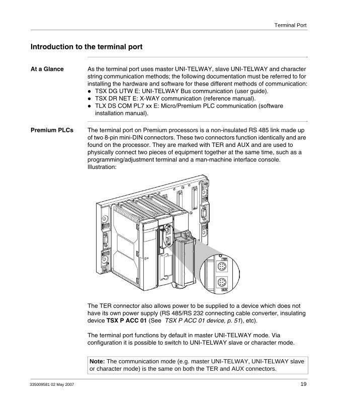
Premium PLCs The terminal port on Premium processors is a non-insulated RS 485 link made up of two 8-pin mini-DIN connectors. These two connectors function identically and are found on the processor. They are marked with TER and AUX and are used to physically connect two pieces of equipment together at the same time, such as a programming/adjustment terminal and a man-machine interface console.Illustration:
The TER connector also allows power to be supplied to a device which does not have its own power supply (RS 485/RS 232 connecting cable converter, insulating device TSX P ACC 01 (See TSX P ACC 01 device, p. 51), etc).
The terminal port functions by default in master UNI-TELWAY mode. Via configuration it is possible to switch to UNI-TELWAY slave or character mode.
Note: The communication mode (e.g. master UNI-TELWAY, UNI-TELWAY slave or character mode) is the same on both the TER and AUX connectors.
335009581 02 May 2007 19
Terminal Port
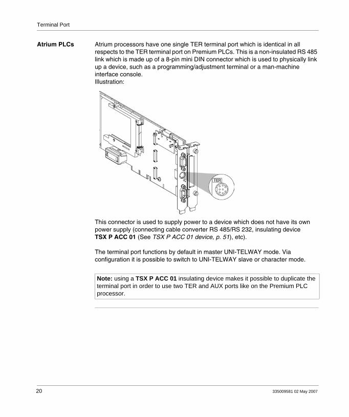
Atrium PLCs Atrium processors have one single TER terminal port which is identical in all respects to the TER terminal port on Premium PLCs. This is a non-insulated RS 485 link which is made up of a 8-pin mini DIN connector which is used to physically link up a device, such as a programming/adjustment terminal or a man-machine interface console.Illustration:
This connector is used to supply power to a device which does not have its own power supply (connecting cable converter RS 485/RS 232, insulating device TSX P ACC 01 (See TSX P ACC 01 device, p. 51), etc).
The terminal port functions by default in master UNI-TELWAY mode. Via configuration it is possible to switch to UNI-TELWAY slave or character mode.
Note: using a TSX P ACC 01 insulating device makes it possible to duplicate the terminal port in order to use two TER and AUX ports like on the Premium PLC processor.
20 335009581 02 May 2007

Terminal Port
Communication with a programming/adjustment terminal
General Configured in master UNI-TELWAY (default function), the terminal port is used to connect a programming/adjustment terminal. Premium station:
Atrium station:
Note: When using an Atrium Station, the programming terminal is generally the PC which accepts the PCX 57 processor. However, as for a Premium station, the programming terminal can also be a PC type terminal connected to the processor port.
Programming/adjustment terminalFT 2010/FTX 517 - PC
Programming/adjustment terminalFT 2010/FTX 517 - PC
PCX 57Programming/adjustment terminal Host PC
335009581 02 May 2007 21
Terminal Port
Communicating with a man-machine interface console
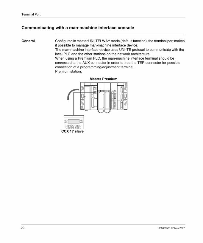
General Configured in master UNI-TELWAY mode (default function), the terminal port makes it possible to manage man-machine interface device.The man-machine interface device uses UNI-TE protocol to communicate with the local PLC and the other stations on the network architecture.When using a Premium PLC, the man-machine interface terminal should be connected to the AUX connector in order to free the TER connector for possible connection of a programming/adjustment terminal.Premium station:
CCX 17 slave
Master Premium
22 335009581 02 May 2007

Terminal Port
Atrium station:
Master Atrium
CCX 17 slave
Host PC
335009581 02 May 2007 23

Terminal Port
UNI-TELWAY master/slave communication
General The default communication mode for the terminal port is master UNI-TELWAY. It is mainly used to link up a programming terminal and a slave man-machine interface console.Illustration:
Client/Server
Client/Server
Client
Slave
Slave
FT 2010/FTX 517 CCX 17
Master Premium
Note: When using an Atrium PLC or if the processor only has one terminal port, this type of connection can be made by using a TSX P ACC 01 device. (See TSX P ACC 01 device, p. 51)
24 335009581 02 May 2007

Terminal Port
Character string communication
General This mode is used to connect up a printer or specialized console (screen control, table controller etc.) to the terminal port of a Premium or Atrium PLC.Illustration
Premium TSX RKY
Atrium
or
or or
or
Control screen
Control screenLoop Controller
Loop Controller
Printer
Printer
335009581 02 May 2007 25

Terminal Port
1.2 Connections
At a Glance
Aim of this Section
This Section deals with the different connections of the Terminal port.
What's in this Section?
This section contains the following topics:
Topic Page
Connections 27
Programming/adjustment terminal 28
Man-machine interface console 30
Programming/adjustment terminal and man-machine interface console 31
Modem on terminal port 32
Master UNI-TELWAY 34
Slave UNI-TELWAY 35
UNI-TELWAY inter-PLC link 36
Inter-device UNI-TELWAY 38
Type TSX, model 40 master PLC 39
Character string 40
Summary table of terminal port connections 43
26 335009581 02 May 2007

Terminal Port
Connections
General The connector marked TER is used to connect any device which supports UNI-TELWAY protocol, in particular devices which do not have their own power supply (RS 485/RS 232 connector cable converters, TSX P ACC 01 (See TSX P ACC 01 device, p. 51) isolation device, etc). The connector marked AUX (only on Premium PLCs) only enables devices which have a power supply to be connected (eg. man-machine interface console, third-party devices, etc).The terminal port has three function modes:
Master UNI-TELWAY (default configuration),Slave UNI-TELWAY,Character string.
Illustration:
Methods of connection
According to the operating mode selected in configuration, the terminal port is used to connect:
Premium PLC programming and adjustment terminalsMan-machine interface devicesAnother PLC, using the TSX P ACC 01 connection deviceUNI-TELWAY devices (sensors/actuators, speed controller etc.)A printer or a control screen (link in character string mode)A modem
Note: For Premium PLCs with two connectors (TER and AUX), the operating mode defined in configuration (master UNI-TELWAY, slave UNI-TELWAY, character mode) is the same for both connectors.
Atrium Premium
Note: Connecting a Premium/Atrium PLC slave to a UNI-TELWAY Bus requires the use of a TSX P ACC 01 device.
335009581 02 May 2007 27

Terminal Port
Programming/adjustment terminal
General points Self-powered terminals (FTX 417, FTX 517) can be connected to either the TER or the AUX connectors of the Premium processors.A non-self-powered terminal must be connected to the TER connector of the processor.The programming terminal uses the UNI-TE protocol to program, tune or troubleshoot the PLC, when offline, and all the station devices.If the PLC is connected in a network architecture, the network transparency makes it possible for the programming terminal to reach all the entities present in the architecture.The references of the different connection cables are given below.
28 335009581 02 May 2007

Terminal Port
Examples of connection:
TS
X F
TX
CB
F 0
20(R
S 4
85)
PC/FT2100
FTX 517
PC/FT2100
Premium TSX RKY
AtriumHost PC
TS
X P
CX
103
1T
SX
PC
X 3
030
(RS
485
/232
)
TS
X P
CX
103
1T
SX
PC
X 3
030
(RS
485
/232
)
OR
OR
Programming/Adjustment
Programming/Adjustment
Programming/Adjustment
Programming/Adjustment
TS
X F
TX
CB
F 0
20(R
S 4
85)
FTX 517
335009581 02 May 2007 29

Terminal Port
Man-machine interface console
General The man-machine interface device uses UNI-TE protocol to communicate with the local PLC and the other stations in the network architecture.A man-machine console with its own power supply on a Premium PLC must be connected to the AUX port in order to leave the TER port free for a terminal which needs a power supply (FTX 117 Adjust for example).The product references for connector cables between the terminal port and a CCX 17 man-machine interface console are given below.Examples of connection:
CCX 17: MMI console
Host PC
CCX 17: MMI console
XBT-Z968
XBT-Z968
T CCX CB10 002(provided with the CCX 17)
T CCX CB10 002(provided with the CCX 17)
Premium TSX RKY
30 335009581 02 May 2007
Terminal Port
Programming/adjustment terminal and man-machine interface console
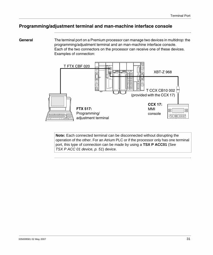
General The terminal port on a Premium processor can manage two devices in multidrop: the programming/adjustment terminal and an man-machine interface console.Each of the two connectors on the processor can receive one of these devices.Examples of connection:
FTX 517:Programming/adjustment terminal
CCX 17:MMI console
XBT-Z 968
T CCX CB10 002(provided with the CCX 17)
T FTX CBF 020
Note: Each connected terminal can be disconnected without disrupting the operation of the other. For an Atrium PLC or if the processor only has one terminal port, this type of connection can be made by using a TSX P ACC01 (See TSX P ACC 01 device, p. 51) device.
335009581 02 May 2007 31

Terminal Port
Modem on terminal port
General The terminal port on Premium PLCs is compatible with a modem connection in all protocols: Master UNI-TELWAY, Slave UNI-TELWAY and Character string.
Modem characteristics
The modem which is to be connected must have the following characteristics:1. Support 10 or 11 bits per character if the terminal port is used in UNI-TELWAY
mode:1 bit for Start8 bits of Data1 bit for StopOdd parity or without parity
2. Operate without any data compression if the terminal port is used in UNI-TELWAY.
3. Be able to be "forced DTR signal" configured for its RS 232 serial port (if the modem is used in response mode), as this signal is not connected by the cable.
4. Operate without flow control (neither hardware: RTS/CTS, or software: XON/XOFF) for its RS 232 serial port, as the cable to be used for the terminal port can only carry TX, RX and GND signals.
5. Operate without data carrier check. Warning: this operating mode also uses RTS and CTS control signals.
6. Accept an incoming telephone call while characters arrive at its RS 232 serial port (if a modem/telephone network is used in response mode on a terminal port configured in master UNI-TELWAY).
Note: It is strongly recommended that you check with your dealer that the above-mentioned characteristics are offered by the intended modem.
32 335009581 02 May 2007

Terminal Port
Examples Connecting to a Premium PLC:
In Master UNI-TELWAY mode with the terminal port connected to a modem/telephone network in response mode, this modem must have all the above characteristics (1 to 6).In character string mode with the terminal port connected to a modem via a specialized line, this modem must have the characteristics of 3 to 5 above.
Configuring the terminal port
In UNI-TELWAY mode the following parameters must be observed and set in the configuration in PL7 software:
The wait timeout must be between 100 and 250 msIn master mode the number of configured slaves must correspond to the actual number of slaves present on the bus.In slave mode the number of addresses must correspond to those used.
Note: Connection on an Atrium is identical.
TSX PCX 1130
TSX CTC 09 adapter if necessary
Modem
335009581 02 May 2007 33
Terminal Port
Master UNI-TELWAY
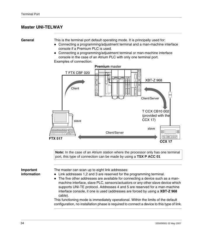
General This is the terminal port default operating mode. It is principally used for:Connecting a programming/adjustment terminal and a man-machine interface console if a Premium PLC is used.Connecting a programming/adjustment terminal or man-machine interface console in the case of an Atrium PLC with only one terminal port.
Examples of connection:
Important information
The master can scan up to eight link addresses:Link addresses 1,2 and 3 are reserved for the programming terminal.The five other addresses are available for connecting a device such as a man-machine interface, slave PLC, sensors/actuators or any other slave device which supports UNI-TE protocol. Addresses 4 and 5 are reserved for a man-machine interface console, it one is used (addresses are forced by using a XBT-Z 968 cable).
This functioning mode is immediately operational. Within the limits of the default configuration, no installation phase is required to connect a device to this type of link.
Premium master
T FTX CBF 020
XBT-Z 968
Client/Server
Client
slave
slaveClient/Server
FTX 517CCX 17
T CCX CB10 002(provided with theCCX 17)
Note: In the case of an Atrium station where the processor only has one terminal port, this type of connection can be made by using a TSX P ACC 01
34 335009581 02 May 2007
Terminal Port
Slave UNI-TELWAY
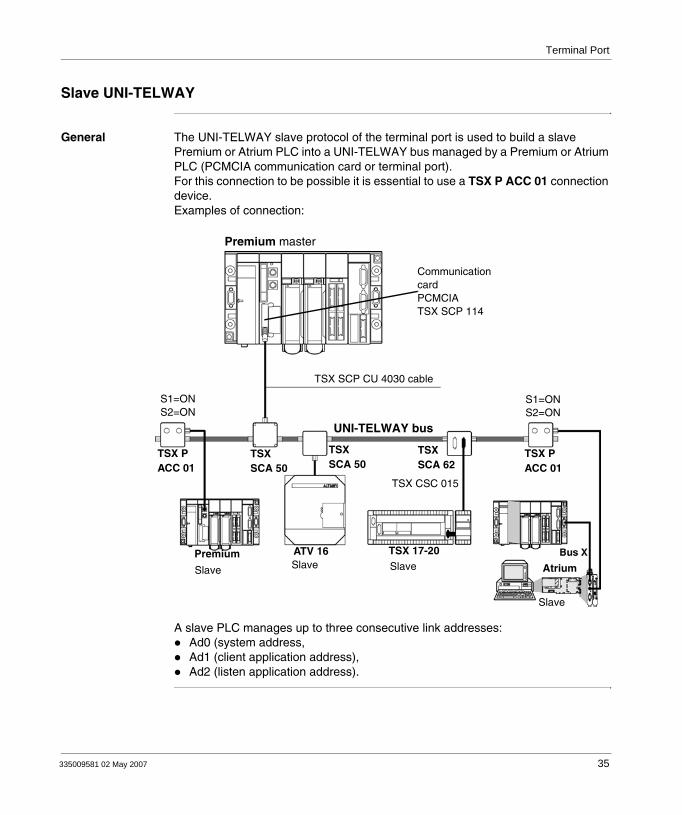
General The UNI-TELWAY slave protocol of the terminal port is used to build a slave Premium or Atrium PLC into a UNI-TELWAY bus managed by a Premium or Atrium PLC (PCMCIA communication card or terminal port).For this connection to be possible it is essential to use a TSX P ACC 01 connection device.Examples of connection:
A slave PLC manages up to three consecutive link addresses:Ad0 (system address,Ad1 (client application address),Ad2 (listen application address).
Premium master
TSX SCP CU 4030 cable
S1=ONS2=ON
UNI-TELWAY bus
S1=ONS2=ON
TSX P ACC 01
TSX SCA 50
TSX SCA 62
TSX P ACC 01
TSX SCA 50
TSX CSC 015
Atrium
Slave
SlaveSlave
Premium ATV 16 TSX 17-20Slave
CommunicationcardPCMCIATSX SCP 114
335009581 02 May 2007 35

Terminal Port
UNI-TELWAY inter-PLC link
General points The terminal port of the Premium processor allows the connection of two PLC’s, one master and the other slave.For this connection it is essential to use a TSX P ACC 01 (See TSX P ACC 01 device, p. 51) branching device. The different possibilities for connecting this device are described below.
Example of connection of two Premium devices
Illustration:
Premium master Premium slave
TSX PCX 1031TSX PCX 3030
FT 2100 slave
T FTX CB 1020/1050
TSX P ACC 01
S1=ONS2=ON
36 335009581 02 May 2007

Terminal Port
Example of connection of one Premium and one Atrium
Illustration:
Premium master TSX RKY
Atrium slave
FT 2100 slaveT FTX CB 1020/1050
TSX PCX 1031TSX PCX 3030
TSX P ACC 01
S1=ONS2=ON
335009581 02 May 2007 37

Terminal Port
Inter-device UNI-TELWAY
General The terminal port on Premium/Atrium PLCs enables them to be connected to a UNI-TELWAY bus in order to communicate with devices such as speed controllers, sensor/actuators or with other PLCsConnecting a Premium/Atrium (master or slave) PLC to a UNI-TELWAY bus requires the use of a TSX P ACC 01 (See TSX P ACC 01 device, p. 51) device.
Example Examples of connection:
The connected devices communicate with the PLC using UNI-TE protocol.
Communication between the different components is allowed.
The programming terminal can directly access all these devices to carry out adjustments and diagnostics functions.
Premium masterFTX 417 slave
T FTX CBF 020 S1=ONS2=ON
TSX P ACC 01 TSX SCA 50
ATV 16 slave
CCX 17
UNI-TELWAY bus
TSX SCA 62
Note: To install TSX SCA 50 and TSX SCA 62 devices, consult the TSX DG UTW manual: UNI-TELWAY Bus communication.
38 335009581 02 May 2007

Terminal Port
Type TSX, model 40 master PLC
General points A model 40 TSX/PMX PLC can also be configured as master of the UNI-TELWAY bus and can control slave Premium/Atrium PLCs.Example of a connection
FT 2... slave
TSX 107-40 master
TSX CSB 015 S1=ONS2=ON
S1=ONS2=ON
TSX PCX 1031TSX PCX 3030
TSX P ACC 01 TSX P ACC 01TSX SCA 62
Premium slave Premium slave
UNI-TELWAY bus
Note: For the implementation of the TSX SCA 50 and TSX SCA 62 devices, consult the TSX DG UTW manual: UNI-TELWAY Bus Link
335009581 02 May 2007 39
Terminal Port
Character string
General points The terminal port, when configured in character mode, can be used to connect a device such as a printer, display screen or a specialized console (table controller for example).
40 335009581 02 May 2007

Terminal Port
Examples of connection:
Note: To allow all types of connection, the TSX PCX 1130 cable is delivered with a TSX CTC 09 adapter/converter (9-pin male to 25-pin male).
Premium TSX RKY
RS485/RS 232 converter cableTSX PCX 1031
Control screen not handling the RTS signal
RS485/RS 232 converter cableTSX PCX 1031
RS485/RS 232 converter cableTSX PCX 1031
Controller
Printer
Host PC
Atrium
Converter cable RS485/RS 232 TSX PCX 1031
Control screen not handling the RTS signal
Controller
Printer
RS485/RS 232 converter cableTSX PCX 1031
RS485/RS 232 converter cableTSX PCX 1031
OR
OR
OR
OR
335009581 02 May 2007 41

Terminal Port
Precautions for use
The TSX PCX 1031 cable allows RS 485/RS 232 conversion and provides ‘peripheral slave’ information for the printer. It does not work on the AUX port and the connected device must handle the RTS signal.To use the TSX PCX 1031 cord, one of the following TER port configurations must be used:
7 data bits + 1 or 2 stop bits + 1 parity bit,7 data bits + 2 stop bits,8 data bits + 1 stop bit + 0 or 1 parity bit,8 data bits + 2 stop bits.
The TSX PCX 1031 and TSX PCX 1130 cables should only be connected to the PLC's TER port in order to supply power to the RS 485/RS 232 conversion device.To avoid signal conflicts, no devices should be connected to the PLC's AUX port.
42 335009581 02 May 2007

Terminal Port
Summary table of terminal port connections
General points The table below specifies the cord linking the connectors of the terminal port of a Premium/Atrium PLC to peripheral devices.
Connecting cord TER port
AUX port
Examples of connected devices
TSX CB 1020TSX CB 1050
X TSX P ACC 01
T FTX CBF 020 X X FTX517, FTX 417
TSX PCX 1031TSX PCX 3030
X FT 2100, RS232 programming and adjustment terminals
TSX PCX 1031 X Graphic and printer terminals handling the RTS signal
XBT-Z968 X X CCX 17, XBT
TSX P ACC 01 X Connection to UNI-TELWAY
TSX PCX 1031 X Devices not handling the DTE <--> DTE type RTS signal: programming terminals, RS 232 printers
TSX PCX 1130 X Devices not handling the DTE <--> DCE type RTS signal: Modem
335009581 02 May 2007 43

Terminal Port
Adjustment of the TSX PCX 1130 cables
The TSX PCX 1130 cable enables the RS 485 and RS 232 signals to be converted. It enables the terminal port to be connected to the RS 232 devices which do not handle the RTS.It is fitted with a switch for setting the PLC to master or slave mode. The switch can be accessed internally, by removing the metal cover which contains the electronics.The switch is used as follows:
Illustration:
UNI-TELWAY Master PL7 configuration
UNI-TELWAY Slave PL7 configuration
Character mode PL7 configuration
Switch position M
UNI-TELWAY Master with PL7 configuration
UNI-TELWAY Master with default configuration
UNI-TELWAY Master with default configuration
Switch position E
UNI-TELWAY Slave with default configuration
UNI-TELWAY Slave with PL7 configuration
Character mode with PL7 configuration
M master mode E slave mode
44 335009581 02 May 2007
Terminal Port
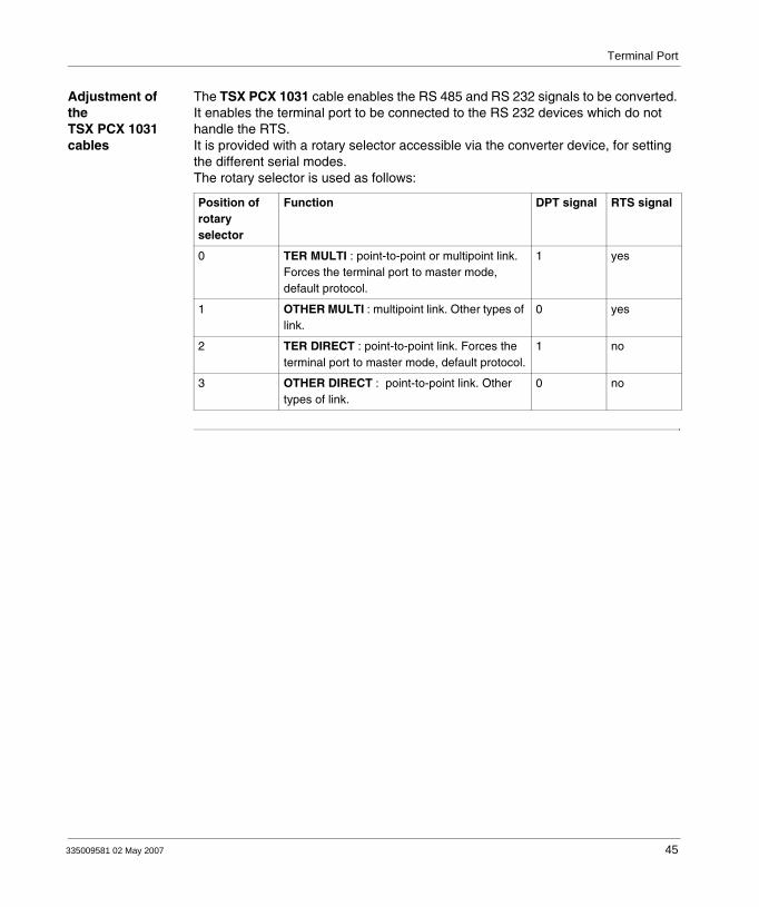
Adjustment of the TSX PCX 1031 cables
The TSX PCX 1031 cable enables the RS 485 and RS 232 signals to be converted. It enables the terminal port to be connected to the RS 232 devices which do not handle the RTS.It is provided with a rotary selector accessible via the converter device, for setting the different serial modes.The rotary selector is used as follows:
Position of rotary selector
Function DPT signal RTS signal
0 TER MULTI : point-to-point or multipoint link. Forces the terminal port to master mode, default protocol.
1 yes
1 OTHER MULTI : multipoint link. Other types of link.
0 yes
2 TER DIRECT : point-to-point link. Forces the terminal port to master mode, default protocol.
1 no
3 OTHER DIRECT : point-to-point link. Other types of link.
0 no
335009581 02 May 2007 45

Terminal Port
Adjustment of the TSX PCX 3030 cables
The TSX PCX 3030 cable enables serial signals to be converted via a USB RS 485 and RS 232 connection.It is provided with a rotary selector accessible via the converter device, for setting the different serial modes.The rotary selector is used as follows:
Position of rotary selector
Function DPT signal
0 TER MULTI : multipoint link (1). 1
1 OTHER MULTI : multipoint link. Other types of link. 0
2 TER DIRECT : point-to-point link (1). 1
3 OTHER DIRECT : point-to-point link. Other types of link. 0
(1) : Modbus slave PLC link (Twido), default protocol. Uni-Telway master PLC link (Nano, Micro, Premium, Neza), default protocol.
Note: A single TSX PCX 3030 cable connection is supported for each PC.
Note: To avoid disturbing the PLC/PC link, it is advisable to terminate any other connection in progress via the USB ports of the PC.
46 335009581 02 May 2007

Terminal Port
1.3 Appendices
At a Glance
Aim of this Section
This Section contains the appendices relating to the Terminal port.
What's in this Section?
This section contains the following topics:
Topic Page
Characteristics of the terminal port 48
Terminal port connector pin configuration 50
335009581 02 May 2007 47

Terminal Port
Characteristics of the terminal port
General The following table describes the characteristics of the terminal port:
UNI-TELWAY mode (master or slave)
Character Mode
Structure Physical interface
non-isolated RS 485 non-isolated RS 485
Transmission Protocol Master/slave multidrop No protocol
Binary rate 19,200 bits/s by default, modifiable from 1,200 to 19,200 bits/s (1 start bit; 8 data bits; even, odd or no parity; 1 stop bit).
9,600 bits/s by default, modifiable from 1,200 to 19,200 bits/s (7 or 8 data bits; even, odd or no parity; with or without echo).
Configuration Number of devices
Maximum eight (eight addresses managed by the master). In slave mode, addresses 4, 5, 6 are selected by default. In master mode, the reserved addresses are:
1, 2 and 3 for the programming terminal4 and 5 if a CCX 17 is present
The other addresses are available.
One (point to point) device
Length 10 meters maximum 10 meters maximum
48 335009581 02 May 2007

Terminal Port
Utilities UNI-TE Point to point requests with maximum 128-byte reports at the initiative of every connected device. There is no broadcast at the initiative of the master.
Maximum 120-byte character string. Messages must end with $0D (carriage return).
Other functions Transparent communication between all devices within a network architecture via the master.
-
Safety A control character on each frame, acknowledgement and possible repetition.
No error reported.
Monitoring Table indicating bus state, device states and error counters accessible on slaves
No flow control.
Note: Using a TSX P ACC 01 (See TSX P ACC 01 device, p. 51) connection device means the RS 485 link can be used in isolated mode.
Note: We strongly recommend that, after use, you do not leave a TSX PCU 103• or TSX PCX 1031 cable connected to the Uni-telway bus at one end and unconnected at the other.
UNI-TELWAY mode (master or slave)
Character Mode
335009581 02 May 2007 49

Terminal Port
Terminal port connector pin configuration
General The terminal port connectors marked TER and AUX are 8-pin mini-DIN which can be locked.The signals are given below:
The table below defines the functioning mode of the terminal port according to these two parameters:
Note: The operation of the terminal port depends on two parameters:Signal status/DTP (0 or 1), fixed by cabling accessory (TSX P ACC 01 cable).Software configuration of the terminal port defined in PL7.
PL7 configuration Signal /DTP = 0 Signal /DTP = 1
Master UNI-TELWAY
Terminal port in UNI-TELWAY slave mode (default)
Terminal port in UNI-TELWAY master mode
Slave UNI-TELWAY
Terminal port in UNI-TELWAY slave mode
Terminal port in UNI-TELWAY master mode (default)
Character mode Terminal port in character mode Terminal port in UNI-TELWAY master mode (default)
1 D (B)2 D (A)3 not connected4 /DE5 /DTP (1 = master)6 not connected7 0 volt8 5 volts
1 D (B)2 D (A)3 not connected4 /DE5 /DTP (1 = master)6 not connected7 0 volt8 not connected
50 335009581 02 May 2007
335009581 02 May 2007
2
TSX P ACC 01 deviceAt a Glance
Aim of this Chapter
This Chapter introduces the functions of the TSX P ACC 01 connection device.
What's in this Chapter?
This chapter contains the following sections:
Section Topic Page
2.1 At a Glance 52
2.2 Hardware installation 55
2.3 Example of topologies 62
51

TSX P ACC 01
2.1 At a Glance
At a Glance
Aim of this Section
This Section describes the general characteristics of the TSX P ACC 01 device.
What's in this Section?
This section contains the following topics:
Topic Page
Functionalities 53
External appearance 54
52 335009581 02 May 2007
TSX P ACC 01
Functionalities
General The TSX P ACC 01 unit is a cabling accessory that connects to the TER connector of the Premium/Atrium PLC processor via an integral cable fitted with a mini-DIN connector at one end.This is used to:
Connect several devices to the terminal port of Premium/Atrium PLCs. For this purpose, it is fitted with two mini-DIN connectors, marked TER and AUX, which are functionally identical to the TER and AUX connectors of the Premium PLC processors.Isolate Uni-Telway signals in order to extend Premium PLC terminal port links to over 10 meters for the purpose of connecting the PLC to a Uni-Telway bus.Adapt the bus when the unit is connected to one of the ends of the Uni-Telway bus.Set the operating mode of the terminal port:
Uni-Telway master,Uni-Telway slave or Character Mode.
Note: The TER and AUX ports of the TSX P ACC 01 unit are not isolated from one another, nor from the TER port of the supplying PLC.
Note: We strongly recommend that, after use, you do not leave a TSX PCU 103• or TSX PCX 1031 cable connected to the Uni-telway bus at one end and unconnected at the other.
335009581 02 May 2007 53
TSX P ACC 01
External appearance
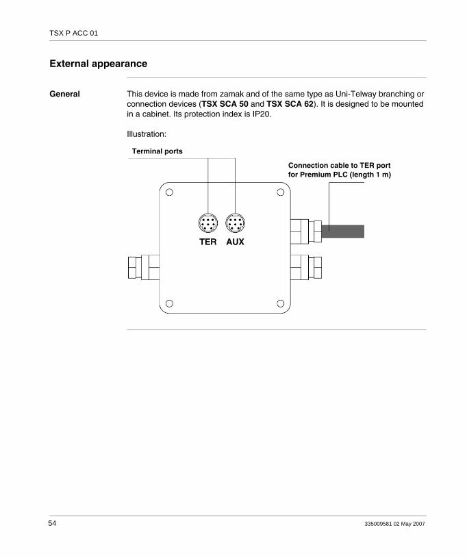
General This device is made from zamak and of the same type as Uni-Telway branching or connection devices (TSX SCA 50 and TSX SCA 62). It is designed to be mounted in a cabinet. Its protection index is IP20.
Illustration:
Terminal ports
Connection cable to TER portfor Premium PLC (length 1 m)
54 335009581 02 May 2007

TSX P ACC 01
2.2 Hardware installation
At a Glance
Aim of this Section
This Section deals with installing hardware for connection devices TSX P ACC 01.
What's in this Section?
This section contains the following topics:
Topic Page
Dimensions and mounting 56
Internal view 57
Connection to Uni-Telway Buses 58
Connecting to Premium and Atrium PLCs 59
Switch configuration 60
TSX P ACC 01 connector pin configuration 61
335009581 02 May 2007 55

TSX P ACC 01
Dimensions and mounting
General The TSX P ACC 01 device is installed on a AM1-PA••• perforated board or on a DIN rail with a LA9 D09976 mounting plate.
Illustration:
2 x Ø 5.5
50
65=
=
= =
AM1-PA...
AM1-DE/DP
56 335009581 02 May 2007

TSX P ACC 01
Internal view
Illustration
S1 Selects functioning mode (master or slave),
S2 Adapts the line end,
JA and JB Connection terminals on the Uni-Telway Bus.
S1
S M
JBJA
S2
Z
12
34
5
12
34
5
335009581 02 May 2007 57

TSX P ACC 01
Connection to Uni-Telway Buses
General The TSX P ACC 01 device is connected to the Uni-Telway Bus using connection terminals JA and JB as shown below:
Illustration:
Shielding
Insulating sleeve(essential)
White
Red
White
Blue
58 335009581 02 May 2007

TSX P ACC 01
Connecting to Premium and Atrium PLCs
General When the TSX P ACC 01 device has to be supplied, it must be connected by its built-in cable to the TER connector on the PLC processor.The device can be connected and disconnected when the PLC is switched on.Illustration:
Note:Only one TSX P ACC 01 device can be connected to a Premium/Atrium PLC.
TSX P ACC 01
Premium TSX RKY
TSX P ACC 01
Host PC
Atrium
335009581 02 May 2007 59

TSX P ACC 01
Switch configuration
General Configuring line end adaptationLine ends are adapted by the S2 switch as indicated below.Configuring the operating modeThe operating mode is selected by switch S1 as indicated below.
Illustration:
End of line positionUNI-TELWAY
UNI-TELWAYslave or
character mode
UNI-TELWAY masterOther positions
Note: The operating mode selected only concerns the connection cable leading to the TER connector on the PLC processor.
60 335009581 02 May 2007

TSX P ACC 01
TSX P ACC 01 connector pin configuration
General The TSX P ACC 01 device has two parallel connectors, marked TER and AUX.The signals are given below :
1 D(B)2 D(A)3 not connected4 not connected5 not connected6 not connected7 0 V8 5 V
1 D(B)2 D(A)3 not connected4 not connected5 not connected6 not connected7 not connected8 not connected
335009581 02 May 2007 61
TSX P ACC 01
2.3 Example of topologies
At a Glance
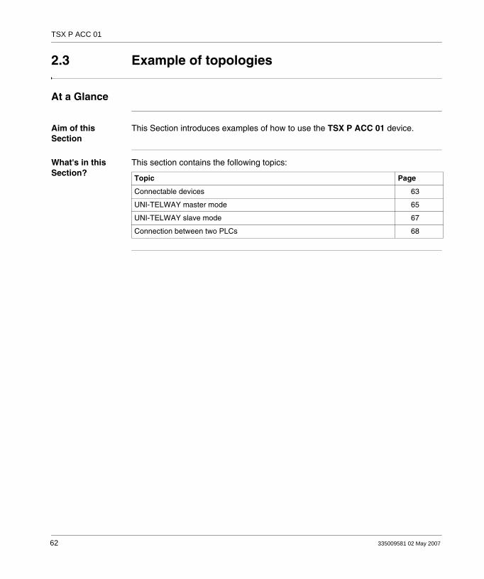
Aim of this Section
This Section introduces examples of how to use the TSX P ACC 01 device.
What's in this Section?
This section contains the following topics:
Topic Page
Connectable devices 63
UNI-TELWAY master mode 65
UNI-TELWAY slave mode 67
Connection between two PLCs 68
62 335009581 02 May 2007

TSX P ACC 01
Connectable devices
General The functionalities of the TER and AUX ports of the TSX P ACC 01 unit are identical to those of the TER and AUX connectors from the Premium/Atrium PLC processors.
The unit's TER connector is used to connect any device supporting UNI-TELWAY protocol, in particular non-supplied devices (RS 485/RS 232 converter lead, etc.).The unit's AUX connector cannot be used to connect devices with a power supply (operator dialog console, third party devices, etc.).
Example 1:
Note: The TSX P ACC 01 unit is supplied by the TER connector of the PLC to which it is connected. The unit's TER connector can therefore be used to supply self-powered devices (CCX 17, etc.) or non- powered devices (RS 485/RS 232 converter lead, etc.).If you wish to connect the terminal port of a second PLC to one of the ports of the TSX P ACC 01 unit, it is essential that you use the AUX connectors (from the unit and the PLC) in order not to put the supplies of the two PLCs into conflict.
Note: We strongly recommend that, after use, you do not leave a TSX PCU 103• or TSX PCX 1031 cable connected to the Uni-telway bus at one end and unconnected at the other.
Premium master Premium slave
TSX P ACC 01
T FTX CB 1020/1050
335009581 02 May 2007 63
TSX P ACC 01
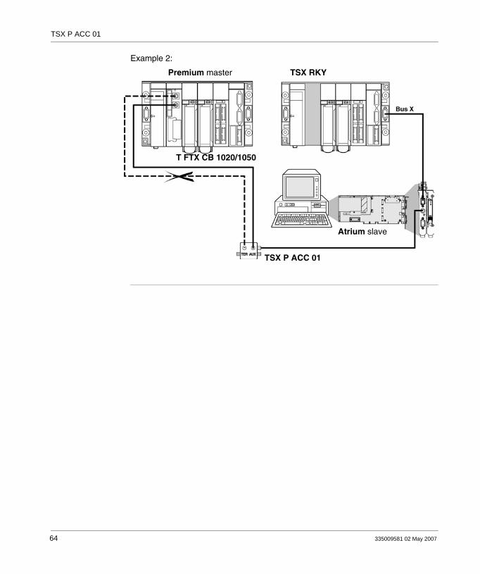
Example 2:
TSX P ACC 01
Atrium slave
TSX RKYPremium master
T FTX CB 1020/1050
64 335009581 02 May 2007

TSX P ACC 01
UNI-TELWAY master mode
Example The way to connect a TSX P ACC 01 device to a master PLC of the UNI-TELWAY link is shown in the example below.Switches S1 and S2 must be set to OFF (master mode). Example for Premium station:
FT 2100 slave Premium master
UNI-TELWAY bus
S1=OFFS2=OFFTSX PCX 1031
TSX PCX 3030
TSX P ACC 01
XBT Z 968
T CCX CB 10 002
TSX SCA 50
ATV 16 slave
1000 meters maximum
CCX 17 slave
TSX SCA 62
Addresses 1, 2, 3
Address 6 Addresses 4/5 Addresses 7/8
TSX CSC 015
TSX 17-20 slave
335009581 02 May 2007 65

TSX P ACC 01
Example for Atrium station:
TSX RKY
Host PC
Atrium master
UNI-TELWAY busS1=OFFS2=OFFTSX PCX 1031
TSX PCX 3030
TSX P ACC 01
XBT Z 968
T CCX CB 10 002
TSX SCA 50
ATV 16 slave
1000 meters maximum
CCX 17 slave
TSX SCA 62
Addresses 1, 2, 3
Address 6 Addresses 4/5 Addresses 7/8
TSX CSC 015
TSX 17-20 slave
FT 2100 slave
66 335009581 02 May 2007

TSX P ACC 01
UNI-TELWAY slave mode
Example The way to connect a TSX P ACC 01 device to a slave PLC of the UNI-TELWAY link is shown in the example below.
Illustration:
Note: Important: To enable a PLC to operate in slave mode, it must be connected to a TSX P ACC 01 device by the built-in cable.
TS
X P
CX
103
1T
SX
PC
X 3
030
TSX 107-40 master
S1=ONS2=ON
S1=ONS2=ON
TSX P ACC 01TSX SCA 62
TSX P ACC 01
Premium
XBT Z 968
Atrium slave
CCX 17
TCCX CB10 002
UNI-TELWAY bus
TSX CSB 015
FT 2100
1000 meters maximum
335009581 02 May 2007 67
TSX P ACC 01
Connection between two PLCs
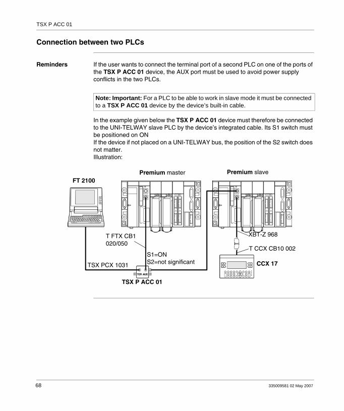
Reminders If the user wants to connect the terminal port of a second PLC on one of the ports of the TSX P ACC 01 device, the AUX port must be used to avoid power supply conflicts in the two PLCs.
In the example given below the TSX P ACC 01 device must therefore be connected to the UNI-TELWAY slave PLC by the device’s integrated cable. Its S1 switch must be positioned on ONIf the device if not placed on a UNI-TELWAY bus, the position of the S2 switch does not matter.Illustration:
Note: Important: For a PLC to be able to work in slave mode it must be connected to a TSX P ACC 01 device by the device’s built-in cable.
FT 2100
TSX PCX 1031
TSX P ACC 01
S1=ONS2=not significant CCX 17
T CCX CB10 002
Premium slavePremium master
XBT-Z 968T FTX CB1020/050
68 335009581 02 May 2007
335009581 02 May 2007
II
Processor-integrated master FIPIO communicationAt a Glance
Aim of this Part This Part deals with the master FIPIO communication function, which is integrated into Premium/Atrium processors.
What's in this Part?
This part contains the following chapters:
Chapter Chapter Name Page
3 Processor-integrated master FIPIO communication 71
69

Integrated FIPIO
70 335009581 02 May 2007
335009581 02 May 2007
3
Processor-integrated master FIPIO communicationAt a Glance
Aim of this Chapter
This Chapter deals with the FIPIO communication function integrated into Premium/Atrium processors.
What's in this Chapter?
This chapter contains the following topics:
Topic Page
Review of the FIPIO bus 72
Integrated FIPIO link on Premium/Atrium processors 74
Examples of architecture 75
71
Integrated FIPIO
Review of the FIPIO bus
General FIPIO is a field bus which is used to centralize inputs/outputs of a PLC station and its industrial peripherals nearest to the section which is operating.From a PLC station whose processor has a built-in FIPIO link, the FIPIO bus is used to connect 1 to 127 devices such as:
Momentum remote input/output modules (discrete and analog)TBX remote input/output modules (discrete and analog)CCX 17 command consolesATV 16 variable speed controllersDevices which conform to standard profilesAgent PLCs, PC...
The FIPIO field bus can be used in a single architecture (mono-station) or in a more complex architecture (multi-station) where several FIPIO segments can be brought together by a local network at a higher level such as FIPWAY or Ethernet TCP_IP for example.
72 335009581 02 May 2007

Integrated FIPIO
Main characteristics
Structure
Nature Open field bus, conforming to World FIP standards.
Topology Links devices through chaining or branching.
Access method Managed by a bus arbiter
Communication By exchange of variables which can be accessed by the user in the form of PL7 objects and X-WAY datagrams.
Privileged exchanges Cyclical exchange of status variables and remote input/output commands
Transmission
Binary flow 1Mb/s.
Medium Shielded twisted pair (150 Ohms of characteristic impedance).
Configuration
Number of connection points
128 logic connection points for whole architecture
Number of segments 15 maximum (in cascade format) using electrical or optical relays (14 maximum in cascade format).
PLC One PLC (address connection point 0)
Programming terminal One programming terminal (must be connected to connection point 63).
Length The length of a segment depends on its type of branches:1000 meters maximum without relay.15000 meters maximum between the devices which are the furthest apart.
335009581 02 May 2007 73

Integrated FIPIO
Integrated FIPIO link on Premium/Atrium processors
General Some processors have as standard an integrated master FIPIO link which makes it possible to connect the PLC station to a FIPIO bus. Illustration:
Connecting to the FIPIO bus
The processor has a SUB D 9-pin connector which is used to link it to the FIPIO bus using a TSX FP ACC12 connector.Illustration:
The complete procedure for installing a FIPIO bus (architecture, type of cable to use, cabling accessories etc.) is discussed in the FIPIO Bus reference manual.
LinkFIPIO Link
FIPIO
LinkFIPIO
Premium processor Atrium processor
TSX FPACC12
TSX FPACC12
Note: The master FIPIO link integrated into processors should not be taken into account when counting the station channels.
74 335009581 02 May 2007

Integrated FIPIO
Examples of architecture
Premium station Illustration:
Premium TSX RKY
TBX
Momentum
CCX 17
ATV
PC
X Bus
335009581 02 May 2007 75

Integrated FIPIO
Atrium station Illustration:
PC
PC
Atrium
TSX RKY
TBX
Momentum
CCX 17
ATV
76 335009581 02 May 2007
335009581 02 May 2007
III
AS-i bus interface: TSX SAY 100 moduleAt a Glance
Aim of this Part This Part deals with the AS-i bus interface module: TSX SAY 100.
What's in this Part?
This part contains the following chapters:
Chapter Chapter Name Page
4 AS-i bus interface module: TSX SAY 100 79
77

TSX SAY 100
78 335009581 02 May 2007

335009581 02 May 2007
4
AS-i bus interface module: TSX SAY 100At a Glance
Aim of this Chapter
This Chapter only deals with hardware installation of the TSX SAY 100 interface module, AS-i bus master on a Premium/Atrium PLC. For the complete installation of an AS-i bus you must refer to the following manuals:
AS-i bus reference manualAS-i installation section in the Premium PLC Applications Manual - Applications, Volume 1.
What's in this Chapter?
This chapter contains the following sections:
Section Topic Page
4.1 Review of the AS-i bus 80
4.2 Description of the TSX SAY 100 module 90
4.3 Input/output object addressing 102
4.4 AS-i Bus diagnostics 103
4.5 Operating modes of the TSX SAY 100 module 110
4.6 Precautions of use 112
79

TSX SAY 100
4.1 Review of the AS-i bus
At a Glance
Aim of this Section
This Section introduces the main characteristics of the AS-i bus.
What's in this Section?
This section contains the following topics:
Topic Page
Review of the AS-i bus 81
Overview of AS-i products from the Schneider catalog 82
Introduction to the main constituent elements 83
Example of AS-i bus topology 87
Main characteristics of the AS-i bus 88
80 335009581 02 May 2007

TSX SAY 100
Review of the AS-i bus
General The AS-i bus is a field bus (level 0) and can be used to connect sensors/actuators. This allows "Discrete" type information to be routed between a bus master and sensor/actuator slaves.AS-i is made up of three major basic elements:
A dedicated power supply providing 30 VDC voltage.A bus master.Slaves (sensors and actuators).
The main types of sensors/actuators
1. Communication sensors/actuators:With a built-in AS-i function they link up directly to the AS-i bus via a passive distributor or a T-piece connection.
2. The traditional IP65 sensors/actuators:They connect to the bus via an AS-i interface (active distributor or Telefast IP20 discrete input-output bus interface). These interfaces connect the sensors and traditional actuators to the AS-i bus and provide them with dialog capacity on the bus.
Illustration:
Active distributor
AS-i Bus
AS-i function viainterface
Traditional product Communicating product Communicating product
Passive distributorConnection T
AS-i functionintegrated
AS-i functionintegrated
124 products maximum(124 input information
and 124 output information)31 products (sensors or actuators)
335009581 02 May 2007 81
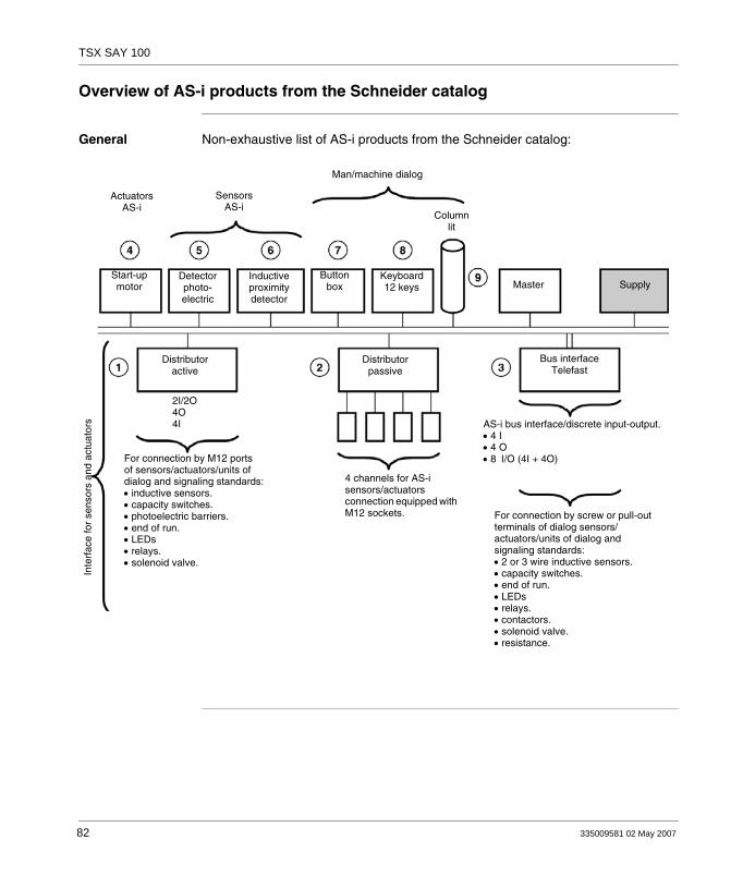
TSX SAY 100
Overview of AS-i products from the Schneider catalog
General Non-exhaustive list of AS-i products from the Schneider catalog:
Start-upmotor
Detectorphoto-electric
Inductiveproximitydetector
Buttonbox
Keyboard 12 keys
Columnlit
Master Supply
Distributoractive
Bus interfaceTelefast
Distributorpassive
ActuatorsAS-i
SensorsAS-i
Man/machine dialog
2I/2O4O4I
For connection by M12 portsof sensors/actuators/units ofdialog and signaling standards:• inductive sensors.• capacity switches.• photoelectric barriers.• end of run.• LEDs• relays.• solenoid valve.
4 channels for AS-i sensors/actuators connection equipped with M12 sockets.
AS-i bus interface/discrete input-output.• 4 I• 4 O• 8 I/O (4I + 4O)
For connection by screw or pull-out terminals of dialog sensors/actuators/units of dialog and signaling standards:• 2 or 3 wire inductive sensors.• capacity switches.• end of run.• LEDs• relays.• contactors.• solenoid valve.• resistance.
Inte
rfac
e fo
r se
nsor
s an
d ac
tuat
ors
82 335009581 02 May 2007

TSX SAY 100
Introduction to the main constituent elements
Cable This transmits data and carries the power. It can be made up from:either an unshielded, polarized twin-wire AS-i ribbon cable.Or a standard round, shielded or unshielded twin-wire cable.
Illustration:
Active distributors
IP67 sealed interfaces for connecting sensors/actuators using M12 connectors. These distributors are used to connect "traditional", non-communicating sensors/actuators.Illustration:
Guiding ribbon cable Round cable
Active distributorfor ribbon cable Active distributor for
round cable
335009581 02 May 2007 83
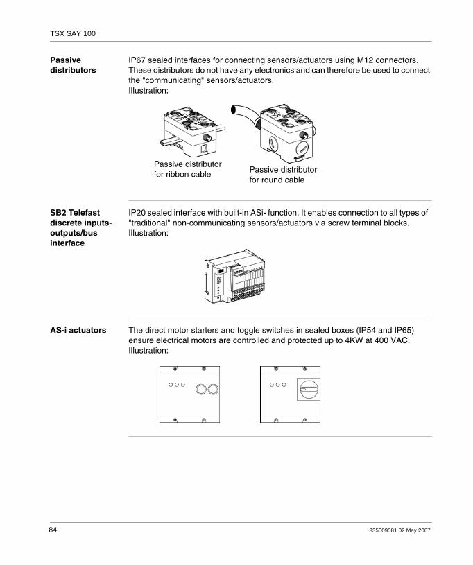
TSX SAY 100
Passive distributors
IP67 sealed interfaces for connecting sensors/actuators using M12 connectors. These distributors do not have any electronics and can therefore be used to connect the "communicating" sensors/actuators.Illustration:
SB2 Telefast discrete inputs-outputs/bus interface
IP20 sealed interface with built-in ASi- function. It enables connection to all types of "traditional" non-communicating sensors/actuators via screw terminal blocks.Illustration:
AS-i actuators The direct motor starters and toggle switches in sealed boxes (IP54 and IP65) ensure electrical motors are controlled and protected up to 4KW at 400 VAC.Illustration:
Passive distributorfor ribbon cable Passive distributor
for round cable
84 335009581 02 May 2007
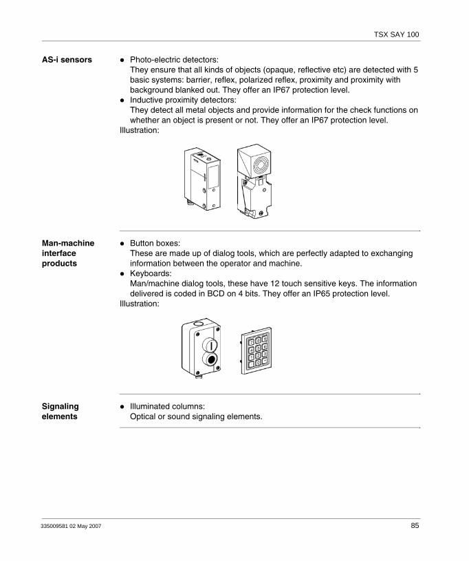
TSX SAY 100
AS-i sensors Photo-electric detectors:They ensure that all kinds of objects (opaque, reflective etc) are detected with 5 basic systems: barrier, reflex, polarized reflex, proximity and proximity with background blanked out. They offer an IP67 protection level.Inductive proximity detectors:They detect all metal objects and provide information for the check functions on whether an object is present or not. They offer an IP67 protection level.
Illustration:
Man-machine interface products
Button boxes:These are made up of dialog tools, which are perfectly adapted to exchanging information between the operator and machine.Keyboards:Man/machine dialog tools, these have 12 touch sensitive keys. The information delivered is coded in BCD on 4 bits. They offer an IP65 protection level.
Illustration:
Signaling elements
Illuminated columns:Optical or sound signaling elements.
335009581 02 May 2007 85

TSX SAY 100
Bus master Built into a Premium/Altrium PLC station, the TSX SAY 100 module (AS-i bus master) manages all data exchanges on the AS-i bus.Illustration:
AS-i power supply
AS-i dedicated power supply, designed to supply the components connected to the AS-i bus.The distribution of this power supply uses the same medium as that used for data exchange.Illustration:
Connecting and branching accessories
T-piece connectors are used to make connections to the AS-i bus. These are designed for linking to AS-i ribbon cables or to ribbon/round cable branches.Illustration:
Premium/Atrium station
T forribbon cable
Branchribbon/round cable
86 335009581 02 May 2007
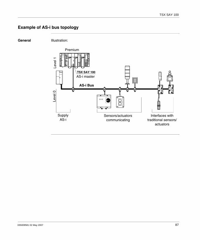
TSX SAY 100
Example of AS-i bus topology
General Illustration:
SupplyAS-i
Sensors/actuatorscommunicating
Interfaces withtraditional sensors/
actuators
AS-i master
PremiumLe
vel 0
Leve
l 1
AS-i Bus
335009581 02 May 2007 87

TSX SAY 100
Main characteristics of the AS-i bus
General AS-i is a system in which exchange management is ensured by a single master who calls in succession, by scanning the bus, each detected slave and awaits a response.The communication series frame carries:
4 data bits (D0 to D3), which are the image of inputs or outputs according to the nature of the interface.4 parametering bits (P0 to P3), which are used to set the operating modes of the interface.P0 to P3 bits are used for "intelligent" devices, including AS-i ASIC (specific integrated circuit). Operation can be modified while it is running.
The address of the slave is coded on 5 bits.At the request of the AS-i master, outputs are set and the inputs for AS-i devices are sent in the slave’s response.
Slave addressing Each slave connected to the AS-i bus must have an address between 1 and 31 (coding on 5 bits).The slaves delivered from the factory have the address 0 (the address of the slave is memorized in a non-volatile format).Addresses are programmed using a terminal specifically for addressing, a XZMC11.
Identification of slaves
All slave devices connected to the AS-i bus are identified by:An I/O Code (input/output distribution code).An identification code, which completes the functional identification of the slave.
These identifications allow the AS-i master to recognize the configuration which is present on the busThese different profiles have been developed by the AS-i Association. They are used to distinguish modules such as for inputs, outputs, mixed modules, "intelligent" device families, etc.
Maximum number of inputs/outputs
An AS-i bus can support a maximum of 31 slaves.Each slave can have a maximum of 4 inputs and/or 4 outputs.This makes it possible to manage a maximum of 124 inputs + 124 outputs, or 240 discrete inputs/outputs when all active devices have 4 inputs and outputs.
Note: When replacing a faulty slave whose address has been set, the address of the slave to be replaced can be updated automatically.
88 335009581 02 May 2007

TSX SAY 100
AS-i cable The AS-i cable is a twin-wire link on which communications and power supply for the connected devises are transmitted. The link does not need to be twisted.
The cross-section of wires can be from 2 x 0.75 mm2, 2 x 1.5 mm2 or 2 x 2.5 mm2, according to the current consumed by the devices.
Topology and maximum length of AS-i bus
The topology of the AS-I bus is flexible. It can be perfectly adapted to meet the user’s needs (point to point, on line, tree structure etc.).In every case, the total length of all the branches of the bus must not exceed 100 meters without a relay.
AS-i bus cycle time
This is the cycle time between slave(s) and the TSX SAY 100 module.The AS-i system always transmits information which is the same length to each slave on the bus. The AS-i cycle time depends on the number of slaves connected to the bus.In the presence of 31 functioning slaves, this time period will be a maximum of 5 ms.
Reliability, flexibility
Reliable operation is ensured by the transmission process used (Manchester current and coding modulation). The master monitors the line supply voltage and the data sent. It detects transmission errors as well as slave failures, and sends the information to the PLC.Exchanging or connecting a new slave during operation does not disturb communications between the master and the other slaves.
335009581 02 May 2007 89
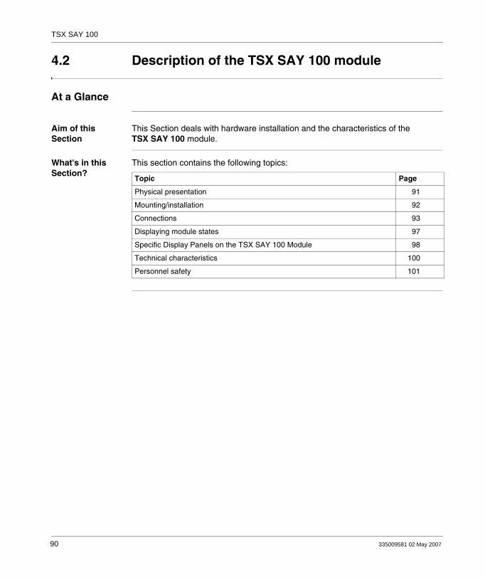
TSX SAY 100
4.2 Description of the TSX SAY 100 module
At a Glance
Aim of this Section
This Section deals with hardware installation and the characteristics of the TSX SAY 100 module.
What's in this Section?
This section contains the following topics:
Topic Page
Physical presentation 91
Mounting/installation 92
Connections 93
Displaying module states 97
Specific Display Panels on the TSX SAY 100 Module 98
Technical characteristics 100
Personnel safety 101
90 335009581 02 May 2007

TSX SAY 100
Physical presentation
General The TSX SAY 100 module comes as a standard format module.Illustration:
Description of TSX SAY 100 module
The module is made up of the following elements:1. A display panel consisting of 4 LEDs for displaying the operating modes of the module:
RUN LED (green): lit indicates normal functioning mode of the module.ERR LED (red): lit indicates a module error.COM LED (green): lit indicates data exchanges on the AS-i network.I/O LED (red): lit indicates an external input/output error on the AS-i bus.
2. Display panel consisting of 32 LEDs (0 to 31) which enable AS-i bus diagnostics, and display the state of each slave connected to the bus.
3. AS-i LED (red): lit indicates an AS-i power supply error.4. Bus LED (green): lit indicates that display panel2 is in BUS display mode (slaves
displayed on the bus).5. I/O LED (green): lit indicates that display panel 2 is in Slave "SLV" display mode
(displays status of input/output bits for a selected slave).6. Push button "↑↓" designed for local diagnostics of the AS-i bus. You can move
between the different AS-i bus diagnostic modes by pressing this button (long or quick presses), combined with the "+/-" push button.
7. Push button "+/−" designed for local diagnostics of the AS-i bus. You can move between the different AS-i diagnostics modes by pressing this button (long or quick presses), combined with the "↑↓" push button.
8. CANNON SUB D connector for connection to AS-i bus.
Front panel
335009581 02 May 2007 91

TSX SAY 100
Mounting/installation
General The TSX SAY 100 module can be mounted in any position on the TSX RKY rack, except for those positions dedicated to processors and power supply.
Inserting and extracting the module is the same as the general procedure for inserting and extracting modules on Premium PLCs (see the Premium PLC installation manual.)Example of mounting a TSX SAY 100 module:
Number of modules per station
The maximum number of modules per Premium/Atrium PLC station depends on the type of processor installed:
Note: In the event where the module is mounted on a remote X Bus rack, the maximum allowed distance from the processor must be 175 meters minus the length of the X Bus (max. 100 m).
Note: The module can be mounted and removed with both PLC and AS-i bus power switched on.
Processors Maximum number of AS-i bus connections
Maximum number of TSX SAY 100 modules
57-1xx 2 2
57-2xx 4 4
57-3xx/57-4xx 8 8
92 335009581 02 May 2007
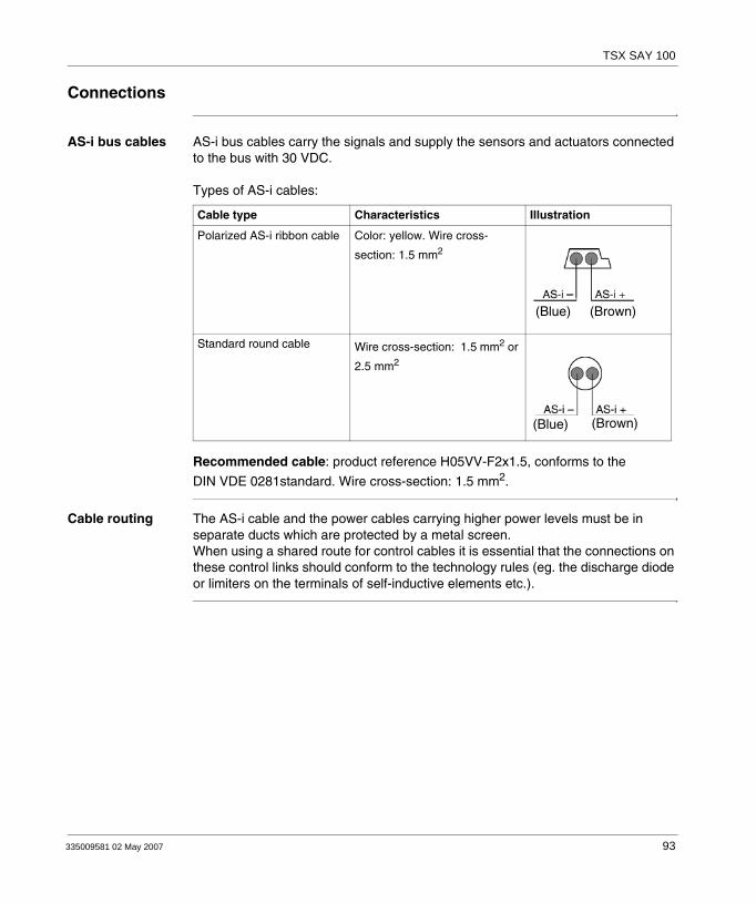
TSX SAY 100
Connections
AS-i bus cables AS-i bus cables carry the signals and supply the sensors and actuators connected to the bus with 30 VDC.
Types of AS-i cables:
Recommended cable: product reference H05VV-F2x1.5, conforms to the
DIN VDE 0281standard. Wire cross-section: 1.5 mm2.
Cable routing The AS-i cable and the power cables carrying higher power levels must be in separate ducts which are protected by a metal screen.When using a shared route for control cables it is essential that the connections on these control links should conform to the technology rules (eg. the discharge diode or limiters on the terminals of self-inductive elements etc.).
Cable type Characteristics Illustration
Polarized AS-i ribbon cable Color: yellow. Wire cross-
section: 1.5 mm2
Standard round cable Wire cross-section: 1.5 mm2 or
2.5 mm2
(Blue) (Brown)
(Blue) (Brown)
335009581 02 May 2007 93
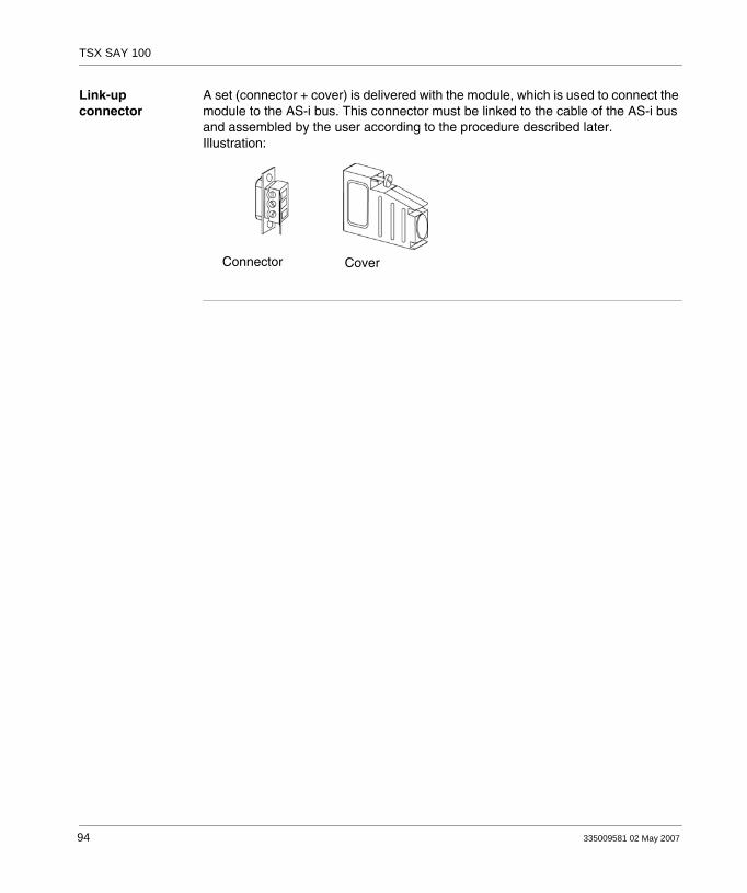
TSX SAY 100
Link-up connector
A set (connector + cover) is delivered with the module, which is used to connect the module to the AS-i bus. This connector must be linked to the cable of the AS-i bus and assembled by the user according to the procedure described later.Illustration:
Connector Cover
94 335009581 02 May 2007
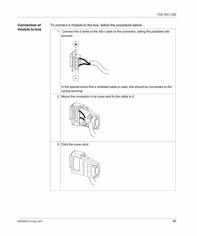
TSX SAY 100
Connection of module to bus
To connect a module to the bus, follow the procedure below:
1 Connect the 2 wires of the AS-i cable to the connector, taking the polarities into account:
In the special event that a shielded cable is used, this should be connected to the central terminal.
2 Mount the connector in its cover and fix the cable to it:
3 Click the cover shut:
335009581 02 May 2007 95

TSX SAY 100
4 Mount the unit on the module:
96 335009581 02 May 2007

TSX SAY 100
Displaying module states
General This is carried out with 4 LEDs RUN, ERR, COM, I/O which are located on the module. Their state (LED off, flashing or on) provides information on the operating mode of the module.
LED state:
LEDs
On Flashing Off
RUN (green)
Module operating normally
Module self-testing (1) Faulty module, or module switched off
ERR (red) Serious internal fault, module broken down
Module self-testing (1) Fault: system OK but:
application fault orAS-i bus error
No internal error
COM (green)
- Module self-testing (1) Communication on AS-i bus
No communication on AS-i bus
I/O (red) Input/output error Module self-testing (1) Module operating normally
(1) the 4 LEDs flash simultaneously during self-testing mode when the module is switched on.
335009581 02 May 2007 97

TSX SAY 100
Specific Display Panels on the TSX SAY 100 Module
General 3 LEDs: AS-i, Bus and I/O display information specific to the TSX SAY 100 module.
View of the 3 LEDs:
AS-i LED (red)
AS-i LED
Bus LED
I/O LED
LED state Meaning
LED on
Module operating normally
Flashing LED
Supply fault on the AS-i bus
LED off
Automatic addressing initialized
98 335009581 02 May 2007

TSX SAY 100
Bus and I/O LEDs These two LEDs display the view mode selected:Bus display mode orSlave display mode.
Display module LED state Meaning
Bus LED on, I/O LED off
The 32 LED display panel located at the front of the module is in BUS display mode and displays all the slaves present on the bus.
Bus LED off, I/O LED on
The 32 LED display panel located on the front of the module is in Slave display mode (SLV) with display of the input/output status for a selected slave.
Bus LED off, I/O LED off
The 32 LED display panel located on the front of the module is in Slave display mode (SLV) with display of the address of the slave selected.
335009581 02 May 2007 99
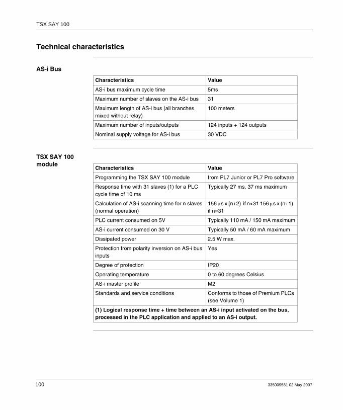
TSX SAY 100
Technical characteristics
AS-i Bus
TSX SAY 100 module
Characteristics Value
AS-i bus maximum cycle time 5ms
Maximum number of slaves on the AS-i bus 31
Maximum length of AS-i bus (all branches mixed without relay)
100 meters
Maximum number of inputs/outputs 124 inputs + 124 outputs
Nominal supply voltage for AS-i bus 30 VDC
Characteristics Value
Programming the TSX SAY 100 module from PL7 Junior or PL7 Pro software
Response time with 31 slaves (1) for a PLC cycle time of 10 ms
Typically 27 ms, 37 ms maximum
Calculation of AS-i scanning time for n slaves (normal operation)
156 μs x (n+2) if n<31 156 μs x (n+1) if n=31
PLC current consumed on 5V Typically 110 mA / 150 mA maximum
AS-i current consumed on 30 V Typically 50 mA / 60 mA maximum
Dissipated power 2.5 W max.
Protection from polarity inversion on AS-i bus inputs
Yes
Degree of protection IP20
Operating temperature 0 to 60 degrees Celsius
AS-i master profile M2
Standards and service conditions Conforms to those of Premium PLCs (see Volume 1)
(1) Logical response time + time between an AS-i input activated on the bus, processed in the PLC application and applied to an AS-i output.
100 335009581 02 May 2007

TSX SAY 100
Personnel safety
General To ensure personnel safety it is essential:To earth the ground terminal of the PLC.To use an AS-i VLSV (very low safety voltage) supply, nominal voltage 30 VDC.For PLCs which are connected to an alternating current network, a differentiel circuit breaker must be placed upstream of this network, and this will cut off the PLC power supply source if ground leakage if detected.For PLCs which are connected to a direct current supply source you must ensure that the supply placed upstream of the PLC is VLVS.To use certified AS-i products on the bus.
Due to its type of technology and connection, the TSX SAY 100 module only receives 5 VDC and its 0V is linked to the PLC ground.
335009581 02 May 2007 101
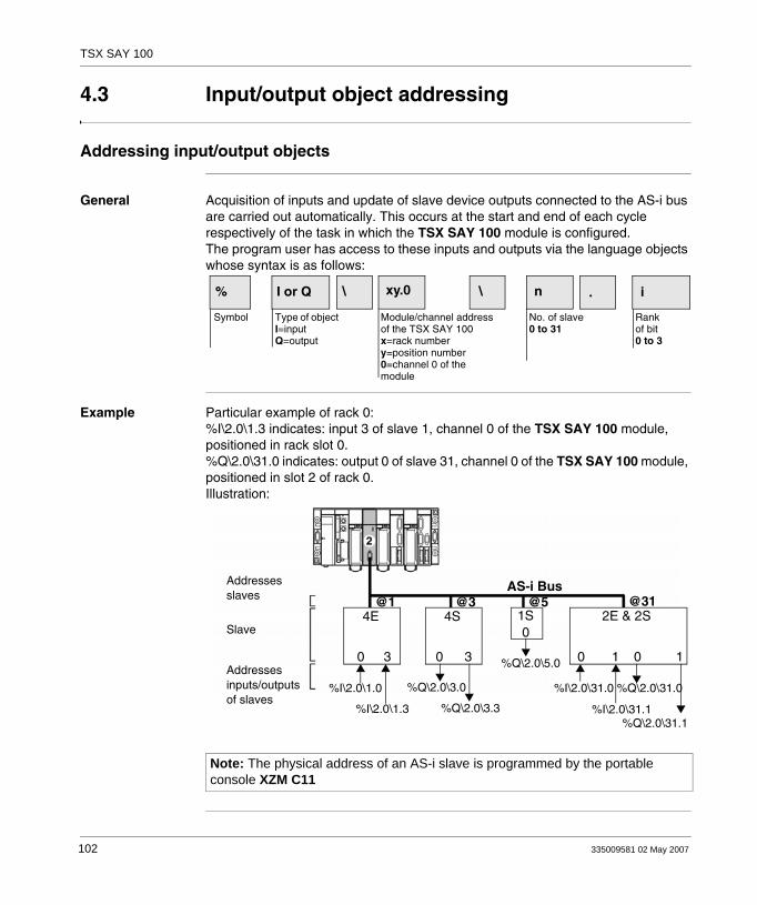
TSX SAY 100
4.3 Input/output object addressing
Addressing input/output objects
General Acquisition of inputs and update of slave device outputs connected to the AS-i bus are carried out automatically. This occurs at the start and end of each cycle respectively of the task in which the TSX SAY 100 module is configured. The program user has access to these inputs and outputs via the language objects whose syntax is as follows:
Example Particular example of rack 0:%I\2.0\1.3 indicates: input 3 of slave 1, channel 0 of the TSX SAY 100 module, positioned in rack slot 0.%Q\2.0\31.0 indicates: output 0 of slave 31, channel 0 of the TSX SAY 100 module, positioned in slot 2 of rack 0.Illustration:
% I or Q \ xy.0 \ n . i
Symbol Type of objectI=inputQ=output
Module/channel addressof the TSX SAY 100x=rack numbery=position number0=channel 0 of the module
No. of slave0 to 31
Rankof bit0 to 3
Note: The physical address of an AS-i slave is programmed by the portable console XZM C11
AS-i Bus
4E 1S4S 2E & 2S@1 @3 @5 @31
%I\2.0\1.0
%I\2.0\1.3
%Q\2.0\3.0
%Q\2.0\3.3
%Q\2.0\5.0
%I\2.0\31.0
%I\2.0\31.1
%Q\2.0\31.0
%Q\2.0\31.1
Addressesslaves
Slave
Addressesinputs/outputsof slaves
0 3 30
0
01 10
102 335009581 02 May 2007
TSX SAY 100
4.4 AS-i Bus diagnostics
At a Glance
Aim of this Section
This Section deals with the diagnostics mode carried out by the TSX SAY 100 module.
What's in this Section?
This section contains the following topics:
Topic Page
Introduction to AS-i Bus diagnostics 104
Moving between the different display modes 106
Display of slaves on the AS-i bus 107
Viewing the state of input/output bits for each slave 108
335009581 02 May 2007 103

TSX SAY 100
Introduction to AS-i Bus diagnostics
General The module display panel is used for:Displaying the presence of each slave on the AS-i bus (Bus mode).Displaying the state of input/output bits of each slave present on the bus (Slave mode "SLV").
These modes can be accessed by a combination of actions on the push buttons (↑↓ and +/-) on the TSX SAY 100 module.Illustration:
104 335009581 02 May 2007

TSX SAY 100
Display modes Table giving the 2 display modes of the module:
Bus mode Slave mode (SLV)
View of AS-i bus image. Each LED 1 to 31 corresponds to a slave address on the bus.
LED on: slave presentflashing LED: slave expected and not detected, or not expected and detected.LED off: slave not expected and not detected.
View of selected slave address.
LED on: number of slave selected.
View of input/output bit state for slave selected.
LEDs 0 to 3 display the state of the input bits.LEDs 4 to 7 display the state of the output bits.LED on: bit in state 1.LED off: bit in state 0 or not significant
Illustration:
View mode is displayed with the Bus LED on and the I/O LED off.
Illustration:
View mode is displayed by Bus and I/O LEDs both off.
Illustration:
View mode is displayed by the Bus LED off and the I/O LED on.
335009581 02 May 2007 105

TSX SAY 100
Moving between the different display modes
Illustration This illustration shows how to move between the different display modes:
On
Off
Display of imageof the AS-i bus(default display)
Off
On
Off
Off
Presenceslaves 1 to 31
Status bitsinput
Status bitsoutput
Display of bitsof I/O of the slaveselected
Display ofaddress ofthe selected slave
Numberof slave
Change direction:Short press on ↑↓
Change slave:Short press on +/-
Hold down on ↑↓
Hold down+/−
Hold downon ↑↓
106 335009581 02 May 2007
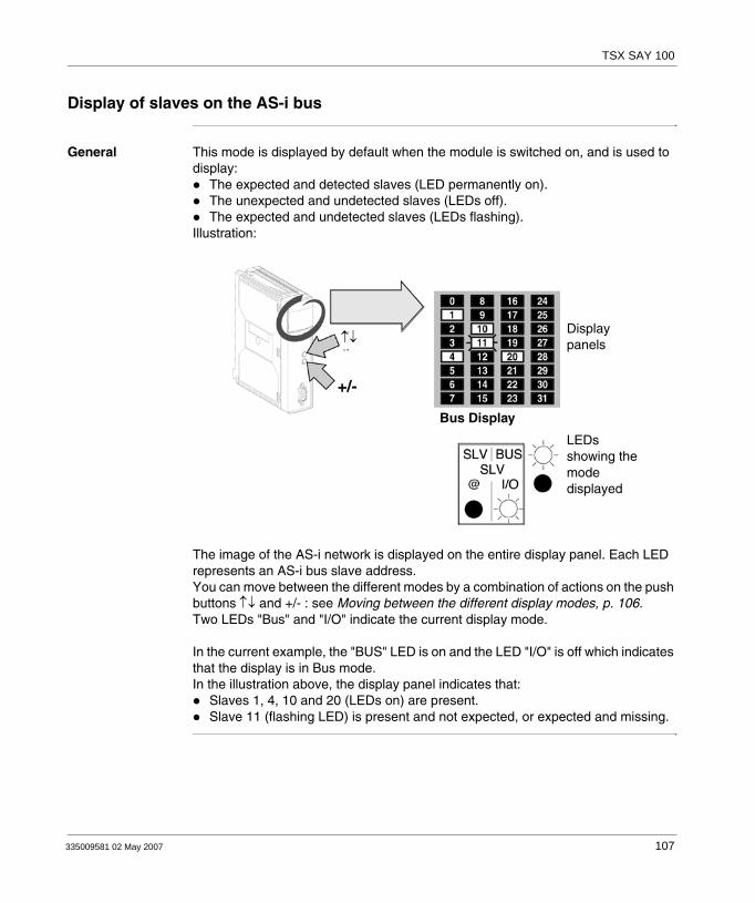
TSX SAY 100
Display of slaves on the AS-i bus
General This mode is displayed by default when the module is switched on, and is used to display:
The expected and detected slaves (LED permanently on).The unexpected and undetected slaves (LEDs off).The expected and undetected slaves (LEDs flashing).
Illustration:
The image of the AS-i network is displayed on the entire display panel. Each LED represents an AS-i bus slave address.You can move between the different modes by a combination of actions on the push buttons ↑↓ and +/- : see Moving between the different display modes, p. 106.Two LEDs "Bus" and "I/O" indicate the current display mode.
In the current example, the "BUS" LED is on and the LED "I/O" is off which indicates that the display is in Bus mode.In the illustration above, the display panel indicates that:
Slaves 1, 4, 10 and 20 (LEDs on) are present.Slave 11 (flashing LED) is present and not expected, or expected and missing.
LEDsshowing themodedisplayed
Displaypanels↑↓
Bus Display
335009581 02 May 2007 107

TSX SAY 100
Viewing the state of input/output bits for each slave
General In this mode (Slave "SLV"), the display panel is used to view the state of input/output bits for each slave present on the bus.
Procedure to be followed
To access the state of input/output bits for a slave from BUS mode, proceed as follows:
Order Action Result
1 Press for more than one second on the button ↑↓
The display switches to Slave "SLV" mode.
2 Press quickly on the +/- button The display of the slave address goes up from 1 to 31.
3 Press quickly on the button ↑↓ The direction of the slave address scan is reversed.
4 Press quickly on the +/- button The display of the slave address goes down from 31 to 1.
5 Pressfor more than one secondon the button +/−
LEDs 0 to 3 display the state of input bits for the slave selected (1).LEDs 4 to 7 display the state of output bits for the slave selected (1).
6 Press quickly on the +/- button The state of inputs-outputs for the following slave is displayed.
7 Press quickly on the button ↑↓ The direction of the slave address scan is reversed.
8 Press quickly on the +/- button The state of input-outputs for the previous slave is displayed.
9 Pressfor more than one second on the button +/−
The display shows again the number of slave selected.
(1) LED on = bit on state 1 LED off = bit on state 0 or no input or output
108 335009581 02 May 2007
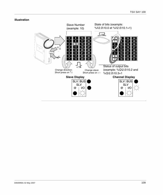
TSX SAY 100
Illustration
State of bits (example:%I\2.0\10.0 et %I\2.0\10.1=1)
Slave Number(example: 10)
↑↓
Change direction:Short press on ↑↓
Change slave:Short press on +/−
Status of output bits(example: %Q\2.0\10.2 and%Q\2.0\10.3=1
Slave Display Channel Display
335009581 02 May 2007 109
TSX SAY 100
4.5 Operating modes of the TSX SAY 100 module
Operating modes of the TSX SAY 100 module
General For more information, refer to the section on AS-i installation in the Premium PLCs Applications Manual - Basic Applications, Volume 1.
Output fallback position
The fallback mode is set in the configuration screen (see Premium PLCs Applications Manual) and can be read in the word %KWxy.0.19:X0:
%Kwxy.0.19:X0 = 1: fallback to 0%KWxy.0.19:X0 = 0: maintain state
(x = rack address, y = module address)
Operation:When the AS-i channel changes to STOP:
With fallback to 0 option: outputs are forced to 0, then communication stops on the medium.With maintain state option: outputs are maintained, then communication stops on the medium.
Automatic slave addressing
When this function is enabled in the module configuration, it allows the replacement of a faulty slave with a slave of the same type without stopping the AS-i bus, and without the need for special action:
If the replacement slave is programmed with the same address and has the same profile, it will be automatically inserted in the list of slaves detected, then activated. If this is not the case, the ERR and AS-i LEDs will flash simultaneously.If the new slave has never been used (address 0, new slave) and has the same profile, the slave automatically takes on the address of the replaced slave and is therefore in the list of detected slaves and the list of active slaves. If this is not the case, the ERR and AS-i LEDs will flash simultaneously.
These actions are only possible if one and only one slave is faulty in the configuration.
Processor error If there is a communication break with the processor, the module switches to SAFETY position.Communication breaks are caused by the following:
Triggering of the processor watchdog if the TSX SAY 100 module is positioned in the rack supporting the processor.Disconnection of the X Bus cable if the TSX SAY 100 module is positioned in an extension rack.
110 335009581 02 May 2007

TSX SAY 100
Module fault In the event of a serious fault on the TSX SAY 100 module (faulty component, etc.) the module stops communicating with the X Bus and with the AS-i Bus. The same type of behavior occurs when a module is removed with the power on.
Removing a module with power switched on
Should a module be removed with the power switched on, communication with the X Bus stops and the processor indicates a module fault.Communication with the AS-i bus is also interrupted without notice. In this case, the slaves with a watchdog set their outputs in the desired state, and the others remain in position and cannot be set to 0 since the module cannot guarantee communication.
Inserting a module with power switched on
After switching on the TSX SAY 100 module, it waits to receive configuration from the processor or for one of the push buttons ↑↓ or +/- to be pressed, otherwise it remains at a stop.
AS-i supply fault When an AS-i supply module fault occurs, communication stops with:Slaves with a watchdog positioning their outputs in the desired state, except if the slave takes its power from the AS-i.Slave commands switch to 0 due to lack of power.
This fault is indicated by the AS-i LED.
Break in the AS-i medium
There are several ways in which a break in the medium can occur:1. There is a break in the medium as it exits the module:
Behavior is the same as that for a power outage, with all slaves disappearing and a supply fault being indicated.
2. There is a break in the medium after the TSX SAY 100 module and the AS-i supply:All slaves disappear and no indication of supply fault.
3. There is a break in the medium after the TSX SAY 100 module, the AS-i supply and some slaves:Slaves located after the break disappear and no indication of supply fault.
335009581 02 May 2007 111

TSX SAY 100
4.6 Precautions of use
At a Glance
Aim of this Section
This Section deals with the precautions to be taken when installing an AS-i bus.
What's in this Section?
This section contains the following topics:
Topic Page
24 V auxiliary supply 113
Multiple addressing 114
112 335009581 02 May 2007

TSX SAY 100
24 V auxiliary supply
Recommen-dations
When slaves use a 24 V auxiliary supply, the disappearance of this supply is not managed by the TSX SAY 100 module.Information on the disappearance of this supply can be accessed by using a 24 V input.
335009581 02 May 2007 113
TSX SAY 100
Multiple addressing
Recommen-dations
When one or more slaves are connected, make sure that you do not assign an address which is already being used by a slave on the bus.
If slave address is doubled then two scenarios may occur:1. The two slaves with identical addresses have the same profile and manage
identical I/Os: the AS-i master bus does not detect any error.2. The two slaves with identical addresses manage different I/Os: the AS-i master
bus can detect transmission errors when accessing the I/O from one of the two slaves.
114 335009581 02 May 2007

335009581 02 May 2007
IV
AS-i V2 bus interface: TSX SAY 1000 moduleAt a Glance
Aim of this Part This part deals with the AS-i V2 TSX SAY 1000 bus interface module.
What's in this Part?
This part contains the following chapters:
Chapter Chapter Name Page
5 AS-i V2 Bus Interface Module: TSX SAY 1000 117
115

TSX SAY 1000
116 335009581 02 May 2007
335009581 02 May 2007
5
AS-i V2 Bus Interface Module: TSX SAY 1000At a Glance
Aim of this Chapter
This chapter deals with hardware installation of the TSX SAY 1000 interface module, AS-i V2 bus master on a Premium/Atrium PLC.
What's in this Chapter?
This chapter contains the following sections:
Section Topic Page
5.1 Introduction to the AS-i Bus 118
5.2 Description of the TSX SAY 1000 Module 125
5.3 Input/Output Object Addressing 135
5.4 AS-i Bus Diagnostics 137
5.5 Operating Modes of the TSX SAY 1000 Module 138
5.6 Precautions of Use 140
5.7 AS-i V2 Certification 143
117
TSX SAY 1000
5.1 Introduction to the AS-i Bus
At a Glance
Aim of this Section
This section introduces the main characteristics of the AS-i bus.
What's in this Section?
This section contains the following topics:
Topic Page
Introduction to the AS-i Bus 119
Overview of AS-i Products from the Schneider Catalog 120
Introduction to the Main Constituent Elements 121
Main Characteristics of the AS-i V2 Bus 122
118 335009581 02 May 2007
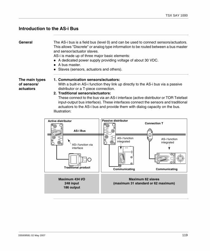
TSX SAY 1000
Introduction to the AS-i Bus
General The AS-i bus is a field bus (level 0) and can be used to connect sensors/actuators. This allows "Discrete" or analog type information to be routed between a bus master and sensor/actuator slaves.AS-i is made up of three major basic elements:
A dedicated power supply providing voltage of about 30 VDC.A bus master.Slaves (sensors, actuators and others).
The main types of sensors/actuators
1. Communication sensors/actuators:With a built-in AS-i function they link up directly to the AS-i bus via a passive distributor or a T-piece connection.
2. Traditional sensors/actuators:These connect to the bus via an AS-i interface (active distributor or TOR Telefast input-output bus interface). These interfaces connect the sensors and traditional actuators to the AS-i bus and provide them with dialog capacity on the bus.
Illustration:
Active distributor
AS-i Bus
AS-i function viainterface
Traditional product Communicating Communicating
Passive distributorConnection T
AS-i functionintegrated
AS-i functionintegrated
Maximum 434 I/O248 input
186 output
Maximum 62 slaves(maximum 31 standard or 62 maximum)
335009581 02 May 2007 119

TSX SAY 1000
Overview of AS-i Products from the Schneider Catalog
General Non-exhaustive list of AS-i products from the Schneider catalog:
Start-upmotor
Inductivephoto-electric
Inductiveproximitydetector
Buttonbox
12 Keykeyboard
Columnlit
Master Supply
Distributoractive
Bus interfaceTelefast
Distributorpassive
ActuatorsAS-i
SensorsAS-i
Man/machine dialog
2I/2O4O4I
For connection by M12 portsof sensors/actuators/units ofdialog and signaling standards:• inductive sensors.• capacity switches.• photoelectric barriers.• end of run.• LEDs• relays.• solenoid valve.
4 channels for AS-i sensors/actuators connection equipped with M12 sockets.
AS-i bus interface/discrete input-output.• 4 I• 4 O• 8 I/O (4I + 4O)
For connection by screw or pull-out terminals of dialog sensors/actuators/units of dialog and signaling standards:• 2 or 3 wire inductive sensors.• capacity switches.• end of run.• LEDs• relays.• contactors.• solenoid valve.• resistance.
Inte
rfac
e fo
r se
nsor
s an
d ac
tuat
ors
120 335009581 02 May 2007

TSX SAY 1000
Introduction to the Main Constituent Elements
Cable This transmits data and carries the power. It can be made up from:either an unshielded, polarized twin-wire AS-i ribbon cable.Or a standard round, shielded or unshielded twin-wire cable.
Illustration:
Bus Master Built into a Premium/Atrium PLC station, the TSX SAY 1000 module (AS-i bus master) manages all data exchanges on the AS-i bus.Illustration:
AS-i Power Supply
AS-i dedicated power supply, designed to supply the components connected to the AS-i bus.The distribution of this power supply uses the same medium as that used for data exchange.Illustration:
Guiding ribbon cable Round cable
Premium/Atrium stationTSX SAY 1000
335009581 02 May 2007 121

TSX SAY 1000
Main Characteristics of the AS-i V2 Bus
General AS-i is a system in which exchange management is ensured by a single master which, by scanning the bus, calls each slave in succession and awaits a response.Communication series frame for slaves with standard AS-i address settings:
4 data bits (D0 to D3), which are the image of inputs or outputs according to the type of interface,4 parametering bits (P0 to P3), which are used to set the operating modes of the interface.
Communication series frame for slaves with extended address settings: 3 or 4 data bits, which are the image of inputs (4 bits, D0 to D3) or outputs (3 bits, D0 to D2) depending on the type of interface,3 parametering bits (P0 to P2), which are used to set the operating modes of the interface.
All slave devices connected to the AS-i bus are identified by at least one "I/O Code" and one "ID code" which completes the functional identification of the slave.Some slaves have an ID1 code, which defines the internal functions of the slave: on analog slaves, for example, ID1 shows the slave's analog channel number.
Slave Addressing
Each slave connected to the AS-i bus must have an address which lies between 1 and 31, either with "Bank" /A, or with "Bank" /B for extended address settings.The slaves delivered from the factory have the address 0 (the address of the slave is memorized in a non-volatile format).Addresses are programmed using a specialized addressing terminal.
Note: The frame base is the same for analog slaves as it is for TOR slaves.There is ascending compatibility between AS-i and AS-i V2. This means that all slaves on the market are supported by SAY 1000.
Note: When replacing a faulty slave whose address has been set, the address of the slave to be replaced can be updated automatically.
122 335009581 02 May 2007

TSX SAY 1000
Identification of Slaves
All standard address setting slaves connected to the AS-i bus are identified by:An I/O Code (input/output distribution code),An identification code, which completes the functional identification of the slave.
All extended address setting slaves connected to the AS-i bus are identified by:An I/O Code (input/output distribution code),An identification code which completes the functional identification of the slave.An ID1 code which defines the internal functions of the slave,An identification code (ID2) which completes the functional identification of the slave.
These identifications allow the AS-i master to recognize the configuration, which is present on the bus.These different profiles have been developed by the AS-i Association. They are used to distinguish between input, output and mixed modules, "intelligent" device families, etc.
Maximum Number of Inputs/Outputs
On the same bus, an AS-i bus can support a maximum of: 31 4I and/or 4O standard address setting slaves, with addresses from 1 to 3162 extended address setting slaves with 4I and/or 3O , using addresses from 1 A/B to 31 A/B.
This makes it possible to manage a maximum of 248 inputs +186 outputs (thus 434 inputs/outputs) when all extended slaves have 4 inputs and 3 outputs.
AS-i Cable The AS-i cable is a twin-wire link on which communications and power supply for the connected devises are transmitted. The link does not need to be twisted.
The cross-section of wires can be from 2 x 0.75 mm2, 2 x 1.5 mm2 or 2 x 2.5 mm2, according to the current consumed by the devices.
Topology and Maximum Length of AS-i Bus
The topology of the AS-i bus is flexible. It can be perfectly adapted to meet the user’s needs (point to point, on line, tree structure etc.).In every case, the total length of all the branches of the bus must not exceed 100 meters without a relay.
335009581 02 May 2007 123

TSX SAY 1000
AS-i Bus Cycle Time
This is the cycle time between slave(s) and the TSX SAY 1000 module.The AS-i system always transmits information, which is the same length to each slave on the bus. The AS-i cycle time depends upon the number of slaves connected to the bus in the presence of functioning slaves.
The scan time t represents the exchange time between a master and n active slaves (a maximum of 31 on /A or /B).So, for:
up to 19 active slaves, t = 3ms20 to 31 active slaves t = (1+n) * 0.156msWhen two slaves A and B have the same address, each slave in the pair is scanned every two cycles.This means that for 31 extended address setting slaves configured in /A, + 31 extended address setting slaves configured in /B. the scan time will be 10 ms.
Maximum cycle time:maximum 5 ms for 31 standard or extended address setting slaves,maximum 10 ms for 62 extended address setting slaves.
Reliability, Flexibility
Reliable operation is ensured by the transmission process used (Manchester current and coding modulation). The master monitors the line supply voltage and the data sent. It detects transmission errors as well as slave failures, and sends the information to the PLC.Exchanging or connecting a new slave during operation does not disturb communications between the master and the other slaves.
124 335009581 02 May 2007
TSX SAY 1000
5.2 Description of the TSX SAY 1000 Module
At a Glance
Aim of this Section
This Section deals with hardware installation and the characteristics of the TSX SAY 1000 module.
What's in this Section?
This section contains the following topics:
Topic Page
Physical Introduction 126
Mounting/Installation 127
Connections 128
Displaying Module States 131
Specific Display Panels on the TSX SAY 1000 Module 132
Technical Characteristics of the AS-i V2 Bus 133
Personnel Safety 134
335009581 02 May 2007 125

TSX SAY 1000
Physical Introduction
General The TSX SAY 1000 module comes as a standard format module.Illustration:
Description of TSX SAY 1000 module
The module is made up of the following elements:1. A display panel consisting of 4 LEDs for displaying the operating modes of the
module:RUN LED (green): lit indicates normal functioning mode of the module.ERR LED (red): when lit, this indicates a module error.I/O LED (red): when lit, this indicates an AS-i bus error./B LED (green): displays standard or /A address setting slaves.
2. Display panel consisting of 32 LEDs (0 to 31) which enable AS-i bus diagnostics, and display the state of each slave connected to the bus.
3. PWR OK LED (green): when lit, this indicates that power supply is consistent.4. FAULT LED (red): when lit, this indicates faults associated with the AS-i bus.5. A/B push button: this button informs the user of the status of devices on the bus
by switching from bank A to bank B.6. MODE push button: holding this button down causes initialization of slaves and a
change to OFF-LINE. This then allows the user to programs the slaves through their infrared interface, or to connect the new diagnostic pocket to the bus. To return to normal mode, just press and hold this button again.
7. CANNON SUB D connector for connection to AS-i bus.
Front panel
PWR OK
126 335009581 02 May 2007
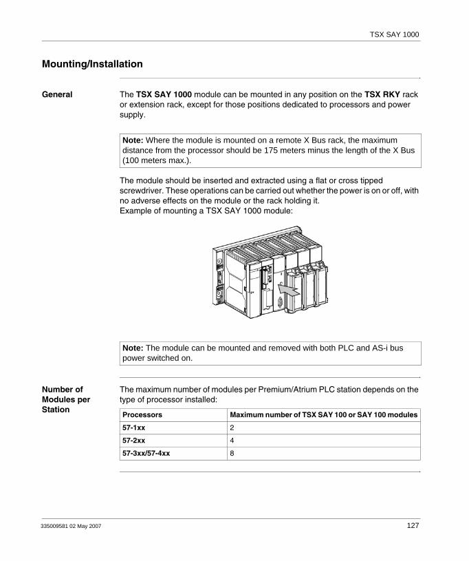
TSX SAY 1000
Mounting/Installation
General The TSX SAY 1000 module can be mounted in any position on the TSX RKY rack or extension rack, except for those positions dedicated to processors and power supply.
The module should be inserted and extracted using a flat or cross tipped screwdriver. These operations can be carried out whether the power is on or off, with no adverse effects on the module or the rack holding it.Example of mounting a TSX SAY 1000 module:
Number of Modules per Station
The maximum number of modules per Premium/Atrium PLC station depends on the type of processor installed:
Note: Where the module is mounted on a remote X Bus rack, the maximum distance from the processor should be 175 meters minus the length of the X Bus (100 meters max.).
Note: The module can be mounted and removed with both PLC and AS-i bus power switched on.
Processors Maximum number of TSX SAY 100 or SAY 100 modules
57-1xx 2
57-2xx 4
57-3xx/57-4xx 8
335009581 02 May 2007 127
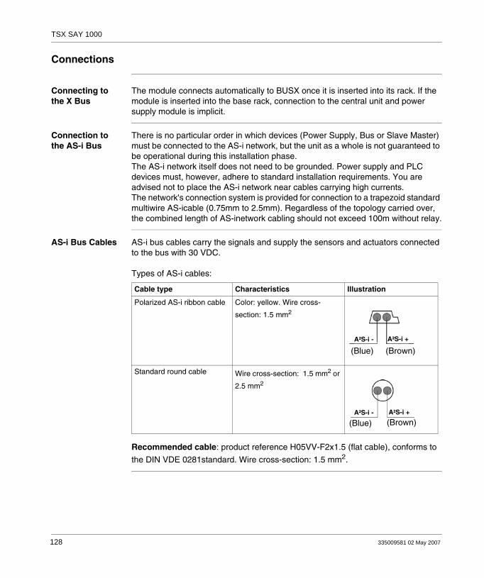
TSX SAY 1000
Connections
Connecting to the X Bus
The module connects automatically to BUSX once it is inserted into its rack. If the module is inserted into the base rack, connection to the central unit and power supply module is implicit.
Connection to the AS-i Bus
There is no particular order in which devices (Power Supply, Bus or Slave Master) must be connected to the AS-i network, but the unit as a whole is not guaranteed to be operational during this installation phase.The AS-i network itself does not need to be grounded. Power supply and PLC devices must, however, adhere to standard installation requirements. You are advised not to place the AS-i network near cables carrying high currents. The network's connection system is provided for connection to a trapezoid standard multiwire AS-icable (0.75mm to 2.5mm). Regardless of the topology carried over, the combined length of AS-inetwork cabling should not exceed 100m without relay.
AS-i Bus Cables AS-i bus cables carry the signals and supply the sensors and actuators connected to the bus with 30 VDC.
Types of AS-i cables:
Recommended cable: product reference H05VV-F2x1.5 (flat cable), conforms to
the DIN VDE 0281standard. Wire cross-section: 1.5 mm2.
Cable type Characteristics Illustration
Polarized AS-i ribbon cable Color: yellow. Wire cross-
section: 1.5 mm2
Standard round cable Wire cross-section: 1.5 mm2 or
2.5 mm2
(Blue) (Brown)A²S-i - A²S-i +
(Blue) (Brown)A²S-i - A²S-i +
128 335009581 02 May 2007

TSX SAY 1000
Cable Routing The AS-i cable and the power cables carrying higher power levels must be in separate ducts, which are protected by a metal screen.When using a shared route for control cables it is essential that the connections on these control links should conform to the technology rules (eg. the discharge diode or limiters on the terminals of self-inductive elements etc.).
Link-up Connector
A set (connector + cover) is delivered with the module, which is used to connect the module to the AS-i bus. This connector must be linked to the cable of the AS-i bus and assembled by the user according to the procedure described later.Illustration:
Connection of Module to Bus
To connect a module to the bus, follow the procedure below:
Connector Cover
1 Connect the 2 wires of the AS-i cable to the connector, taking the polarities into account:
In the special event that a shielded cable is used, this should be connected to the central terminal.
(Blue)
(Brown)
335009581 02 May 2007 129
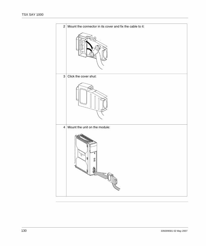
TSX SAY 1000
2 Mount the connector in its cover and fix the cable to it:
3 Click the cover shut:
4 Mount the unit on the module:
130 335009581 02 May 2007
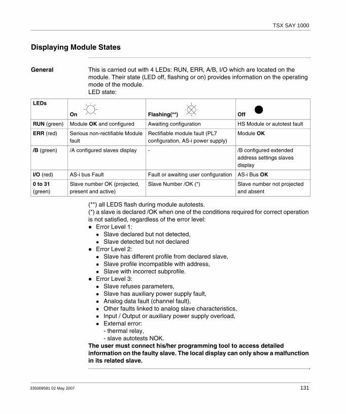
TSX SAY 1000
Displaying Module States
General This is carried out with 4 LEDs: RUN, ERR, A/B, I/O which are located on the module. Their state (LED off, flashing or on) provides information on the operating mode of the module.LED state:
(**) all LEDS flash during module autotests.(*) a slave is declared /OK when one of the conditions required for correct operation is not satisfied, regardless of the error level:
Error Level 1: Slave declared but not detected,Slave detected but not declared
Error Level 2:Slave has different profile from declared slave,Slave profile incompatible with address,Slave with incorrect subprofile.
Error Level 3:Slave refuses parameters,Slave has auxiliary power supply fault,Analog data fault (channel fault),Other faults linked to analog slave characteristics,Input / Output or auxiliary power supply overload,External error:- thermal relay,- slave autotests NOK.
The user must connect his/her programming tool to access detailed information on the faulty slave. The local display can only show a malfunction in its related slave.
LEDs
On Flashing(**) Off
RUN (green) Module OK and configured Awaiting configuration HS Module or autotest fault
ERR (red) Serious non-rectifiable Module fault
Rectifiable module fault (PL7 configuration, AS-i power supply)
Module OK
/B (green) /A configured slaves display - /B configured extended address settings slaves display
I/O (red) AS-i bus Fault Fault or awaiting user configuration AS-i Bus OK
0 to 31 (green)
Slave number OK (projected, present and active)
Slave Number /OK (*) Slave number not projected and absent
335009581 02 May 2007 131

TSX SAY 1000
Specific Display Panels on the TSX SAY 1000 Module
General 2 LEDs: PWR OK and FAULT give specific information on the TSX SAY 1000 module.
View of the 2 LEDs:
PWR OK LED (green)
FAULT LED (Red)
PWR OK LED
FAULT LED
PWR OKFAULT
A/B
MODE
AS-i+
AS-i-
TSX SAY 1000
LED state Meaning
LED on
Power Supply consistent
LED off
Power Supply inconsistent
LED state Meaning
LED on
AS-i bus faults
LED off
No faults
132 335009581 02 May 2007

TSX SAY 1000
Technical Characteristics of the AS-i V2 Bus
AS-i V2 Bus Technical Characteristics:
TSX SAY 1000 Module
Technical Characteristics:
Characteristic Value
Maximum cycle time of bus:- 1 to 19 slaves = 3ms,- 20 to 62 slaves = (1+n)*156s where n = number of active slaves.
maximum 5 ms for 31 standard or extended address setting slaves,maximum 10 ms for 62 extended address setting slaves.
Maximum number of slaves on the bus. 31 standard address setting slaves, or,62 extended address setting slaves.
Maximum length of AS-i bus cables: all branches without relaywith two relays
100 meters300 meters
Maximum number of I/O managed by the bus standard address setting slaves: 124 inputs + 124 outputsextended address setting slaves: 248 inputs + 186 outputs
Nominal bus supply voltage 30 VDC
Characteristic Value
Programming the TSX SAY 1000 module from PL7 Junior, PL7 Pro V4.2, or P-Unit software
Response time with 31 slaves (1) for a PLC cycle time of 10 ms Typically 27 ms, 37 ms maximum
PLC current consumed on 5V Typically 100 mA / 150 mA maximum
Current consumed on 30 V AS-i/AS-i Typically 50 mA / 60 mA maximum
Power dissipation 2.5 W max.
Protection against polarity inversion on bus inputs Yes
Degree of protection IP20
Isolated voltage 500 VDC
Operating temperature 0 to 60 degrees Celsius
AS-i master profile M2e
Standards and service conditions Conforms to those of Premium PLCs (see Volume 1)
(1) Logical response time + time between an AS-i input activated on the bus, processed in the PLC application and applied to an AS-i output.
335009581 02 May 2007 133

TSX SAY 1000
Personnel Safety
General To ensure personnel safety it is essential:To earth the ground terminal of the PLC.To use an AS-i VLSV (very low safety voltage) supply, nominal voltage 30 VDC.For PLCs which are connected to an alternating current network, a differentiel circuit breaker must be placed upstream of this network, and this will cut off the PLC power supply source if ground leakage if detected.For PLCs which are connected to a direct current supply source you must ensure that the supply placed upstream of the PLC is VLVS.To use certified AS-i products on the bus.
Due to the type of technology and connection, the TSX SAY 1000 module only receives 5 VDC and its 0V is linked to the PLC ground.
134 335009581 02 May 2007
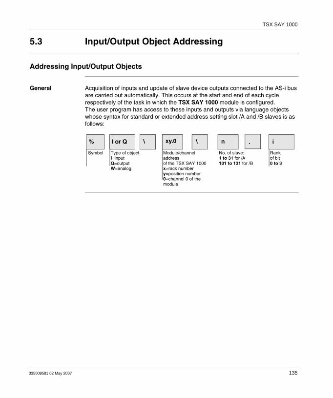
TSX SAY 1000
5.3 Input/Output Object Addressing
Addressing Input/Output Objects
General Acquisition of inputs and update of slave device outputs connected to the AS-i bus are carried out automatically. This occurs at the start and end of each cycle respectively of the task in which the TSX SAY 1000 module is configured. The user program has access to these inputs and outputs via language objects whose syntax for standard or extended address setting slot /A and /B slaves is as follows:
% I or Q \ xy.0 \ n . i
Symbol Type of objectI=inputQ=outputW=analog
Module/channel addressof the TSX SAY 1000x=rack numbery=position number0=channel 0 of the module
No. of slave:1 to 31 for /A101 to 131 for /B
Rankof bit0 to 3
335009581 02 May 2007 135

TSX SAY 1000
Example Particular example of rack 0:%I\2.0\1.3 indicates: input 3 of slave TOR /A 1, channel 0 of the TSX SAY 1000 module, positioned in rack 0 slot 2.%Q\2.0\103.0 indicates: input 0 of slave TOR /B 103, channel 0 of the TSX SAY 1000 module, positioned in rack 0 slot 2.%IW\2.0\31.0 indicates: input 0 of slave ANA /A 31, channel 0 of the TSX SAY 1000 module, positioned in rack 0 slot 2.Illustration:
Note: The physical address of an AS-i slave is programmed by the XZM C11 portable console.An analog slave is configured only on slot /A.The number of an extended TOR /B slave lies between 101 and 131.The number of a standard TOR /A slave, or an ANA slave (which is always standard) lies between 1 and 31.When a standard address setting slave is set at /A, an extended address setting slave at /B cannot have the same address. Only two extended address setting slaves can have the same address at /A and /B.
AS-i Bus
4I 1S4I 4I & 4O@1 @103 @5 @31
%I\2.0\1.0
%I\2.0\1.3
%Q\2.0\103.0
%Q\2.0\103.3
%Q\2.0\5.0
%IW\2.0\31.0
%IW\2.0\31.1
%QW\2.0\31.0
%QW\2.0\31.1
Addressesslaves
Slave
Addressesinputs/outputsof slaves
0 3 30
0
01 10
136 335009581 02 May 2007
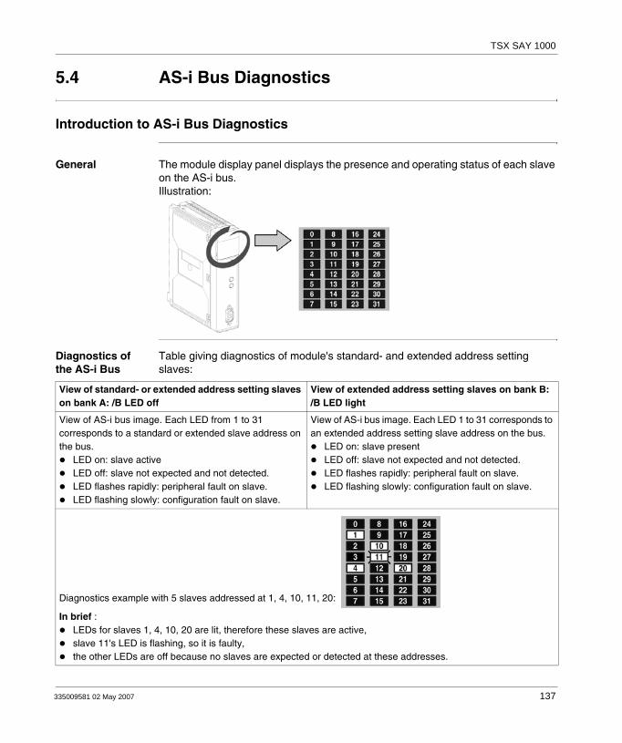
TSX SAY 1000
5.4 AS-i Bus Diagnostics
Introduction to AS-i Bus Diagnostics
General The module display panel displays the presence and operating status of each slave on the AS-i bus.Illustration:
Diagnostics of the AS-i Bus
Table giving diagnostics of module's standard- and extended address setting slaves:
View of standard- or extended address setting slaves on bank A: /B LED off
View of extended address setting slaves on bank B:/B LED light
View of AS-i bus image. Each LED from 1 to 31 corresponds to a standard or extended slave address on the bus.
LED on: slave activeLED off: slave not expected and not detected.LED flashes rapidly: peripheral fault on slave.LED flashing slowly: configuration fault on slave.
View of AS-i bus image. Each LED 1 to 31 corresponds to an extended address setting slave address on the bus.
LED on: slave presentLED off: slave not expected and not detected.LED flashes rapidly: peripheral fault on slave.LED flashing slowly: configuration fault on slave.
Diagnostics example with 5 slaves addressed at 1, 4, 10, 11, 20:
In brief :LEDs for slaves 1, 4, 10, 20 are lit, therefore these slaves are active,slave 11's LED is flashing, so it is faulty,the other LEDs are off because no slaves are expected or detected at these addresses.
335009581 02 May 2007 137
TSX SAY 1000
5.5 Operating Modes of the TSX SAY 1000 Module
Operating Modes of the TSX SAY 1000 Module
General For more information, refer to the section on AS-i installation in the Premium PLCs Applications Manual - Basic Applications, Volume 1(Ref.: TLX DS 57 PL7 V4.2).
Output Fallback Position
Since some AS-i V2 slaves have an internal watchdog based on a communication shutdown, when there is a fallback the module will function in the following way:
fault detection (PLC stop, UC fault, module fault),bus automatically switched OFF LINE by bus master.
Consequences for slaves present on the bus:"old generation" slaves: output maintenance,"new generation" slaves: preprogrammed fallback positions are implemented in the slave.
Automatic Slave Addressing
When this function is enabled in the module configuration, it allows the replacement of a faulty slave with a slave of the same type without stopping the AS-i bus, and without the need for special action:
If the replacement slave is programmed with the same address and has the same profile, it will be automatically inserted in the list of slaves detected, then activated. If this is not the case, the ERR and AS-i LEDs will flash simultaneously.If the new slave has never been used (address 0, new slave) and has the same profile, the slave automatically takes on the address of the replaced slave and is therefore in the list of detected slaves and the list of active slaves. If this is not the case, the ERR and AS-i LEDs will flash simultaneously.
These actions are only possible if one and only one slave is faulty in the configuration.
Communication Fault
If there is a break in communication with the CPU, following a CPU watchdog (where the SAY 1000 module is located in the main rack) or a retraction of the BUSx cable (where the SAY 1000 module is located in the extension rack), the module switches to security mode and stops communication on the AS-i bus.
Module Fault In the event of a serious fault on the TSX SAY 1000 module (faulty component, etc.) the module stops communicating with the X Bus and with the AS-i Bus. The same type of behavior occurs when a module is removed with the power on.
138 335009581 02 May 2007
TSX SAY 1000
Removing a Module with Power Switched On
Should a module be removed with the power switched on, communication with the X Bus stops and the processor indicates a module fault.Communication with the AS-i bus is also interrupted without notice. In this case, the slaves with a watchdog set their outputs in the desired state, and the others remain in position and cannot be set to 0 since the module cannot guarantee communication.
Inserting a module with power switched on
After voltage is applied to the TSX SAY 1000 module, it expects to receive a configuration via PL7. If this does not occur it remains in stop mode.
AS-i Supply Fault When there is an AS-i power supply fault communication stops and the slaves behave differently.
slaves with a watchdog positioning their outputs in the defined state, except if the slave takes its power from the AS-i.all slave commands switch to 0 due to lack of power.
From a language point of view, all slaves seem faulty, and the absence of AS-i power supply is indicated in the Channel Status.
Break in the AS-i Medium
There are several ways in which a break in the medium can occur:1. There is a break in the medium as it exits the module:
Behavior is the same as that for a power outage, with all slaves disappearing and a supply fault being indicated.
2. There is a break in the medium after the TSX SAY 1000 module and the AS-i supply:All slaves disappear and no indication of supply fault.
3. There is a break in the medium after the TSX SAY 1000 module, the AS-i supply and some slaves:Slaves located after the break disappear and no indication of supply fault.
335009581 02 May 2007 139

TSX SAY 1000
5.6 Precautions of Use
At a Glance
Aim of this Section
This Section deals with the precautions to be taken when installing an AS-i bus.
What's in this Section?
This section contains the following topics:
Topic Page
24 VDC Auxiliary Supply 141
Multiple Address Settings 142
140 335009581 02 May 2007
TSX SAY 1000
24 VDC Auxiliary Supply
Recommen-dations
When slaves use a 24 VDC auxiliary supply, the disappearance of this supply is not managed by the TSX SAY 1000 module.Information on the disappearance of this supply can be accessed by using a 24 VDC input.
335009581 02 May 2007 141

TSX SAY 1000
Multiple Address Settings
Recommen-dations
When one or more slaves are connected, make sure that you do not assign an address, which is already being used by a slave on the bus.
WARNINGDouble slave addressingThe two slaves with identical addresses have the same profile and manage identical I/Os: the AS-i master bus does not detect any error.The two slaves with identical addresses manage different I/Os: the AS-i master bus can detect transmission errors when accessing the I/O from one of the two slaves.
Failure to follow this precaution can result in death, serious injury, or equipment damage.
142 335009581 02 May 2007
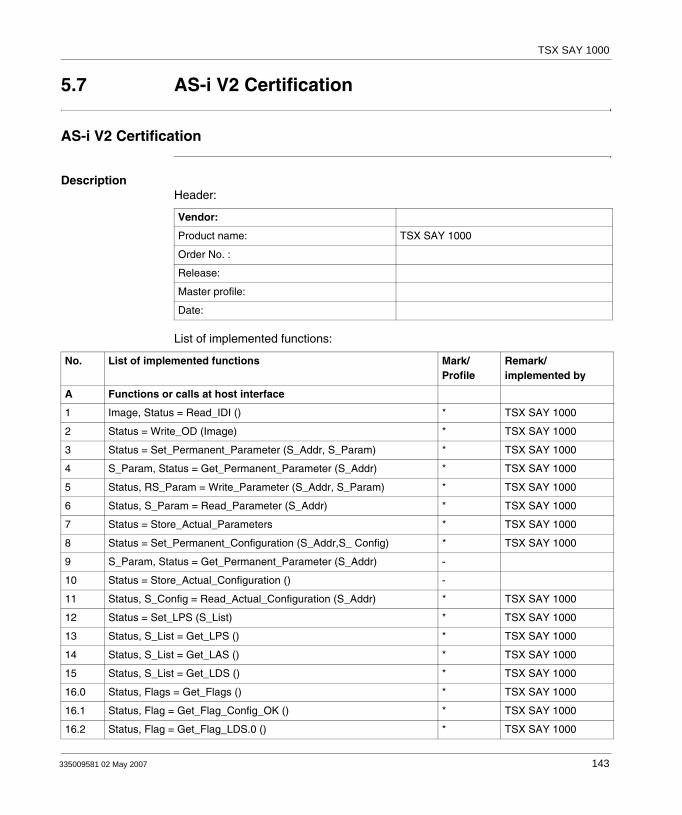
TSX SAY 1000
5.7 AS-i V2 Certification
AS-i V2 Certification
DescriptionHeader:
List of implemented functions:
Vendor:
Product name: TSX SAY 1000
Order No. :
Release:
Master profile:
Date:
No. List of implemented functions Mark/Profile
Remark/implemented by
A Functions or calls at host interface
1 Image, Status = Read_IDI () * TSX SAY 1000
2 Status = Write_OD (Image) * TSX SAY 1000
3 Status = Set_Permanent_Parameter (S_Addr, S_Param) * TSX SAY 1000
4 S_Param, Status = Get_Permanent_Parameter (S_Addr) * TSX SAY 1000
5 Status, RS_Param = Write_Parameter (S_Addr, S_Param) * TSX SAY 1000
6 Status, S_Param = Read_Parameter (S_Addr) * TSX SAY 1000
7 Status = Store_Actual_Parameters * TSX SAY 1000
8 Status = Set_Permanent_Configuration (S_Addr,S_ Config) * TSX SAY 1000
9 S_Param, Status = Get_Permanent_Parameter (S_Addr) -
10 Status = Store_Actual_Configuration () -
11 Status, S_Config = Read_Actual_Configuration (S_Addr) * TSX SAY 1000
12 Status = Set_LPS (S_List) * TSX SAY 1000
13 Status, S_List = Get_LPS () * TSX SAY 1000
14 Status, S_List = Get_LAS () * TSX SAY 1000
15 Status, S_List = Get_LDS () * TSX SAY 1000
16.0 Status, Flags = Get_Flags () * TSX SAY 1000
16.1 Status, Flag = Get_Flag_Config_OK () * TSX SAY 1000
16.2 Status, Flag = Get_Flag_LDS.0 () * TSX SAY 1000
335009581 02 May 2007 143

TSX SAY 1000
( - ) = not implemented functions( * ) = implemented functions
16.3 Status, Flag = Get_Flag_Auto_Address_Assign () * TSX SAY 1000
16.4 Status, Flag = Get_Flag_Auto_Prog_Available () * TSX SAY 1000
16.5 Status, Flag = Get_Flag_Configuration_Active () * TSX SAY 1000
16.6 Status, Flag = Get_Flag_Normal_Operation_Active () * TSX SAY 1000
16.7 Status, Flag = Get_Flag_APF () * TSX SAY 1000
16.8 Status, Flag = Get_Flag_Offline_Ready () * TSX SAY 1000
16.9 Status, Flag = Get_Flag_Periphery_OK () * TSX SAY 1000
17 Status = Set_Operation_Mode (Mode) * TSX SAY 1000
18 Status = Set_Offline_Mode (Mode) * TSX SAY 1000
19 Status = Activate_Data_Exchange (Mode) * TSX SAY 1000
20 Status = Change_Slave_Address (S_Addr1, S_Addr2) * TSX SAY 1000
21.1 Status = Set_Auto_Adress_Enable (Mode) * TSX SAY 1000
21.2 Mode = Get_Auto_Adress_Enable () * TSX SAY 1000
22.1 Status, Resp = Cmd_Reset_AS-i_Slave (S_Addr, RESET) -
22.2 Status, Resp = Cmd_Read_IO_Configuration (S_Addr, CONF) -
22.3 Status, Resp = Cmd_Read_Identification_Code(S_Addr, IDCOD) -
22.4 Status, Resp = Cmd_Read_Status (S_Addr, STAT) -
22.5 * Status, Resp = Cmd_Read_Reset_Status (S_Addr,STATRES) -
22.6 Status, Resp = Cmd_Read_Ext_ID-Code_1 (S_Addr, IDCOD1) -
22.7 Status, Resp = Cmd_Read_Ext_ID-Code_2 (S_Addr, IDCOD2) -
23 Status, S_List = Get_ List of Periphery Faults () * TSX SAY 1000
24 Status = Write_Extended_ID-Code_1(S_Ext_ID-Code_1) * TSX SAY 1000
B Integrated support of slave profiles
1 Analog slave profile S7.3 support integrated * TSX SAY 1000
2 Analog slave profile S7.4 support integrated -
No. List of implemented functions Mark/Profile
Remark/implemented by
144 335009581 02 May 2007

335009581 02 May 2007
V
Communication: TSX SCY 11601/21601 modules and PCMCIA cardsAt a Glance
Aim of this Part This Part deals with installing hardware for TSX SCY 11601/21601 communication modules and PCMCIA communication cards.
What's in this Part?
This part contains the following chapters:
Chapter Chapter Name Page
6 At a Glance 147
7 Installing TSX SCY 11601/21601 modules 151
8 Installing PCMCIA cards 177
9 TSX SCA 64 connection device 231
145

TSX SCY 11601/21601
146 335009581 02 May 2007

335009581 02 May 2007
6
At a GlanceAt a Glance
Subject of this Chapter
This chapter deals with the general features on TSX SCY11601/ 21601 modules and PCMCIA communication cards.
What's in this Chapter?
This chapter contains the following topics:
Topic Page
General communication architecture 148
Operating standards 149
147
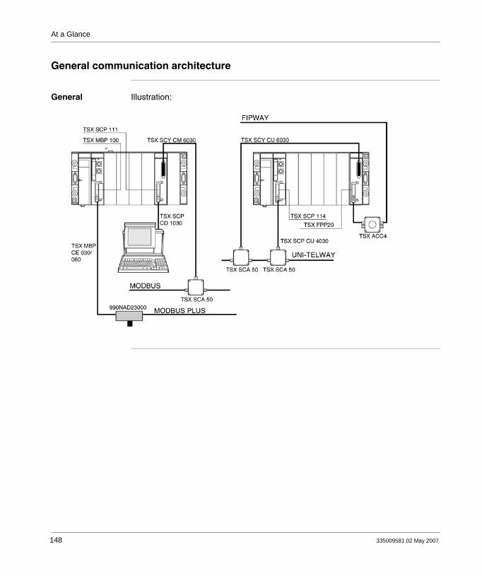
At a Glance
General communication architecture
General Illustration:
148 335009581 02 May 2007
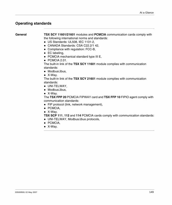
At a Glance
Operating standards
General TSX SCY 11601/21601 modules and PCMCIA communication cards comply with the following international norms and standards:
US Standards: UL508, IEC 1131-2,CANADA Standards: CSA C22.2/1 42,Compliance with regulation: FCC-B,EC labeling,PCMCIA mechanical standard type III E,PCMCIA 2.01.
The built-in link of the TSX SCY 11601 module complies with communication standards:
Modbus/Jbus,X-Way.
The built-in link of the TSX SCY 21601 module complies with communication standards:
UNI-TELWAY,Modbus/Jbus,X-Way.
The TSX FPP 20 PCMCIA FIPWAY card and TSX FFP 10 FIPIO agent comply with communication standards:
FIP protocol (link, network management),PCMCIA,X-Way.
TSX SCP 111, 112 and 114 PCMCIA cards comply with communication standards:UNI-TELWAY, Modbus/Jbus protocols,PCMCIA,X-Way.
335009581 02 May 2007 149

At a Glance
150 335009581 02 May 2007

335009581 02 May 2007
7
Installing TSX SCY 11601/21601 modulesAt a Glance
Subject of this Chapter
This chapter deals with the hardware installation of TSX SCY 11601/21601 modules.
What's in this Chapter?
This chapter contains the following sections:
Section Topic Page
7.1 At a Glance 152
7.2 Description 153
7.3 Built-in Channel Specifications 156
7.4 TSX SCY 21601 module's host channel compatibility 157
7.5 Installation 158
7.6 Operation 160
7.7 Module Visual Diagnostics 161
7.8 Built-in Channel Connection 162
151

TSX SCY 11601/21601
7.1 At a Glance
At a Glance
TSX SCY 11601: General
The TSX SCY11601 communication module is used to communicate via a JBUS/MODBUS link.It comprises a communication channel, channel 0, mono-protocol, isolated RS485 asynchronous serial link supporting the JBUS/MODBUS protocol.
TSX SCY 21601: General
The TSX SCY 21601 communication module is used to host PCMCIA communication cards.It comprises two communication channels:
A multi-protocol built-in channel (channel 0), isolated RS485 asynchronous serial link, supporting UNI-TELWAY, Jbus/Modbus or Character Mode protocols.A PCMCIA host channel (channel 1) which supports the following protocols:
UNI-TELWAY, Jbus/Modbus and Character Mode on an RS 232, Current Loop, or RS 485 link, corresponding to cards TSX SCP 111, 112 and 114.FIPWAY cell network corresponding to the TSX FPP 20card.
Notes for the two modules Note: Important: The built-in channel on TSX SCY 11601/21601 modules is only
compatible with a two wire RS 485 link.
Note: The TSX SCY 11601/21601 communication modules are only compatible with SV software version ≥3.0 Premium/Atrium processors (as indicated on the side label of the processor module).
152 335009581 02 May 2007

TSX SCY 11601/21601
7.2 Description
Description
TSX SCY 11601 module: General
The TSX SCY 11601 module is a standard format module which can be inserted into one of the slots on a Premium/Atrium PLC station rack.
The TSX SCY 11601 module is made up of the following components:
Note: The X bus remote is not authorized for this module.
1. Three indicator LEDs on the front of the module:
RUN and ERR show the module's status.CH0 displays the status of the built-in serial link channel (channel 0) communication.
2. Built-in channel (Channel 0) equipped with a 25 pin SUB-D female connector, half duplex mode (channel 0) RS 485 base link:
Jbus/Modbus
Illustration:
1
2
335009581 02 May 2007 153

TSX SCY 11601/21601
TSX SCY 21601 module: General
The TSX SCY 21601 module is a standard format module which can be inserted into one of the slots on a Premium/Atrium PLC station rack.
The TSX SCY 21601 module is made up of the following components:
Note: The X bus remote is not authorized for this module.
1. Three indicator LEDs on the front of the module:
RUN and ERR show the module's status.CH0 displays the status of the built-in serial link channel (channel 0) communication.
2. Built-in channel equipped with a 25 pin SUB-D female connector, half duplex mode (channel 0) RS 485 base link:
UNI-TELWAYJbus/ModbusCharacter Mode
3. PCMCIA type III (channel 1) card host channel.
Illustration:
Channel 0: built-inchannel
Channel 1: host channel
154 335009581 02 May 2007

TSX SCY 11601/21601
Insertable cards (TSX SCY 21601)
Different types of communication cards which can be built into the TSX SCY 21601 module's host channel:
Type Description Illustration
TSX SCP 111 Multiprotocol card (UNI-TELWAY, Modbus/Jbus, Character Mode), RS 232, 9 non-isolated signals.
TSX SCP 112 Multiprotocol card (UNI-TELWAY, Modbus/Jbus, Character Mode), current loop (BC 20 mA).
TSX SCP 114 Multiprotocol card (UNI-TELWAY, Modbus/Jbus, Character Mode), RS 485, RS 422 compatible isolated.
TSX FPP 20 FIPWAY network cards
335009581 02 May 2007 155
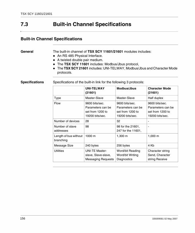
TSX SCY 11601/21601
7.3 Built-in Channel Specifications
Built-in Channel Specifications
General The built-in channel of TSX SCY 11601/21601 modules includes: An RS 485 Physical Interface.A twisted double pair medium.The TSX SCY 11601 includes: Modbus/Jbus protocol,The TSX SCY 21601 includes: UNI-TELWAY, Modbus/Jbus and Character Mode protocols.
Specifications Specifications of the built-in link for the following 3 protocols:
UNI-TELWAY (21601)
Modbus/Jbus Character Mode (21601)
Type Master-Slave Master-Slave Half duplex
Flow 9600 bits/sec. Parameters can be set from 1200 to 19200 bits/sec.
9600 bits/sec. Parameters can be set from 1200 to 19200 bits/sec.
9600 bits/sec. Parameters can be set from 1200 to 19200 bits/sec.
Number of devices 28 32 -
Number of slave addresses
98 98 for the 21601,247 for the 11601,
-
Length of bus without branching
1000 m 1,300 m 1,000 m
Message Size 240 bytes 256 bytes 4 Kb
Utilities UNI-TE Master-slave, Slave-slave, Messaging Requests
Word/bit Reading Word/bit Writing Diagnostics
Character string Send, Character string Receive
156 335009581 02 May 2007

TSX SCY 11601/21601
7.4 TSX SCY 21601 module's host channel compatibility
TSX SCY 21601 Host Channel Compatibility
General The cards supported by the host channel are:
PCMCIA cards: TSX SCP 111, 112, 114 which communicate with Premium/Atrium, 1000 Series and Modicon PLCs and other UNI-TELWAY, Jbus/Modbus and Character Mode compatible products. PCMCIA cards are also Jbus/Modbus compatible with 1000 Series PLCsThe TSX FPP 20 card is compatible with the following FIPWAY devices:
Model 40 PLCs (TSX 47-455, TSX 67-455, etc) in versions later than 5.0.TSX 17 PLCsPC compatibles connected with TSX FPC10 and TSX FPC 20cards.
Note: The TSX FPP 10 card is not supported by the host channel.
335009581 02 May 2007 157

TSX SCY 11601/21601
7.5 Installation
Installation
General The TSX SCY 11601/21601 modules can be installed in a Premium/Atrium PLC station rack.They are part of an X-WAY network architecture based on Series 7, Micro, Premium and Atrium PLCs.
The TSX SCY 11601 communication module brings the following to a PLC station:A JBUS/MODBUS isolated mono-protocol RS 485 communication channel.
The TSX SCY 21601 communication module brings the following to a PLC station:A multi-protocol isolated RS 485 communication channel.A standard PCMCIA communication card slot.
The TSX SCY 11601/21601 modules can be installed in any available slot in a Premium/Atrium PLC station rack.
158 335009581 02 May 2007
TSX SCY 11601/21601
Maximum number of modules
A TSX SCY 11601 module supports up to a maximum of 1 application-specific communication channel, namely the RS 485 channel built into the module.
A TSX SCY 21601 module can support a maximum of 2 application-specific communication channels, a built-in RS 485 channel and a channel from the PCMCIA card which can be integrated into the module.
Since the maximum number of application-specific channels managed by a PLC station depends on the type of processor installed, the number of TSX SCY 11601 or TSX SCY 21601 modules in a station will therefore rely on:
The type of processor installed.The number of application-specific channels already used, other than communication channels.
Consequently, the user must perform an evaluation on his/her PLC station to find out how many application-specific channels are already in use, and thus determine the number of TSX SCY 11601 or TSX SCY 21601 modules which may be used.
A reminder of the number of application-specific channels managed by each type of processor:
Connection/Disconnection
TSX SCY 11601/21601 modules can be connected or disconnected whilst the power is on. These devices do not have a memory save function. When one of the two modules is disconnected from the rack, its internal memory is erased. The module goes through an initialization phase once it is reconnected.A TSX SCY 21601 module which has a PCMCIA card installed may be disconnected when the power is on.
Note: Application-specific channel recognition is defined in the Installation Manual for Premium TSX DM 57 PLCs_Volume 1.
Processors Number of application-specific channels
TSX P57103/TSX P57153 8
TSX P57203 / TSX P57253 / TSX P572623 / TSX P572823 - PCX 57203
24
TSX P57303/TSX P57353 - PCX 57353 / TSX P573623 32
TSX P57453 / TSX P574823 64
Note: However, PCMCIA cards, used in TSX SCY 21601 may not be disconnected while the power is on.
335009581 02 May 2007 159

TSX SCY 11601/21601
7.6 Operation
Operation
TSX SCY 11601 module: General
The TSX SCY 11601 module manages a communication channel (channel 0): channel 0: Jbus/Modbus protocol on an RS 485 half duplex isolated, standardized physical link, with a speed limited to 19200 bits per second.
TSX SCY 21601: General
The TSX SCY 21601 module manages two independent communication channels which each have their own functions:
channel 0 processes UNI-TELWAY, Jbus/Modbus and Character Mode protocols on an RS 485 half duplex isolated, standardized physical link, with a speed limited to 19200 bits per second.channel 1 can take one of the following PCMCIA communication cards:
Field Bus: TSX SCP 111 (RS232), TSX SCP 112 (current loop), TSX SCP 114 (RS 422/RS 485) UNI-TELWAY, Jbus/Modbus and Character mode cards.Cell network: TSX FPP 20 FIPWAY card.
The choice of PCMCIA card and protocol is made when the TSX SCY 21601 module's communication channels are configured using PL7 Junior and PL7 Pro software.
160 335009581 02 May 2007
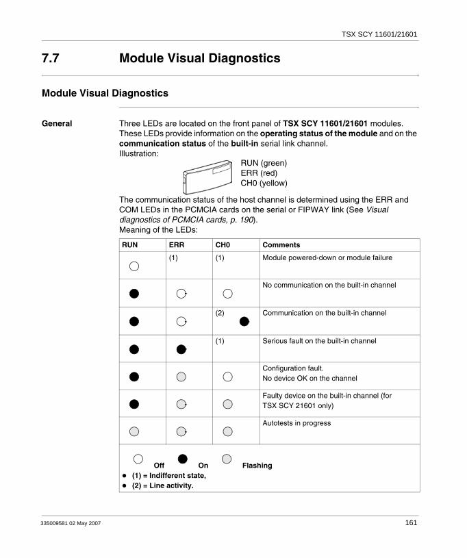
TSX SCY 11601/21601
7.7 Module Visual Diagnostics
Module Visual Diagnostics
General Three LEDs are located on the front panel of TSX SCY 11601/21601 modules. These LEDs provide information on the operating status of the module and on the communication status of the built-in serial link channel. Illustration:
The communication status of the host channel is determined using the ERR and COM LEDs in the PCMCIA cards on the serial or FIPWAY link (See Visual diagnostics of PCMCIA cards, p. 190).Meaning of the LEDs:
RUN ERR CH0 Comments
(1) (1) Module powered-down or module failure
No communication on the built-in channel
(2) Communication on the built-in channel
(1) Serious fault on the built-in channel
Configuration fault.No device OK on the channel
Faulty device on the built-in channel (for TSX SCY 21601 only)
Autotests in progress
Off On Flashing(1) = Indifferent state,(2) = Line activity.
RUN (green)ERR (red)CH0 (yellow)
335009581 02 May 2007 161

TSX SCY 11601/21601
7.8 Built-in Channel Connection
At a Glance
Aim of this Section
This section describes the different ways to connect the built-in channel of TSX SCY 11601/21601 modules.
What's in this Section?
This section contains the following topics:
Topic Page
At a Glance 163
Connection of TSX SCY 21601 to Uni-Telway field bus 165
Reminder on adapting RS 485 distributed line for the TSX SCY 21601 167
Example of Uni-Telway architecture 168
Connection of TSX SCY 11601/21601 modules to the Modbus field bus 169
Reminder on single line polarization in RS 485 170
Example of Modbus architecture 172
Connecting the TSX SCA 50 unit 173
Character Mode connection for TSX SCY 21601 174
Consumption of TSX SCY 11601/21601 modules 175
162 335009581 02 May 2007

TSX SCY 11601/21601
At a Glance
TSX SCY 11601 module: General
Cabling accessories designed to connect the TSX SCY 11601 module's RS 485 base link allow the following connection:
Connection to the Jbus/Modbus network via a TSX SCA 50 unit through the TSX SCY CM 6030 cable or a TSX SCA 64 unit through the TSX SCY CM 6530 cable.
Illustration:
TSX SCY 11601
TSX SCY CM 6030 Cable
RS 485 Built-in Channel
TSX SCY CM 6530 Cable
TSX SCA 64Bus
or
335009581 02 May 2007 163
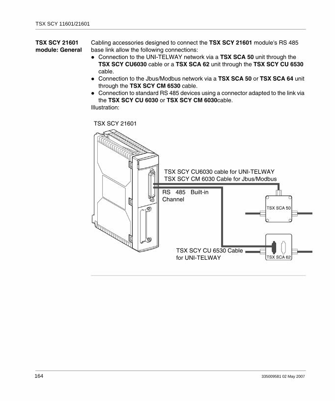
TSX SCY 11601/21601
TSX SCY 21601 module: General
Cabling accessories designed to connect the TSX SCY 21601 module's RS 485 base link allow the following connections:
Connection to the UNI-TELWAY network via a TSX SCA 50 unit through the TSX SCY CU6030 cable or a TSX SCA 62 unit through the TSX SCY CU 6530 cable.Connection to the Jbus/Modbus network via a TSX SCA 50 or TSX SCA 64 unit through the TSX SCY CM 6530 cable.Connection to standard RS 485 devices using a connector adapted to the link via the TSX SCY CU 6030 or TSX SCY CM 6030cable.
Illustration:
TSX SCY 21601
TSX SCY CU6030 cable for UNI-TELWAYTSX SCY CM 6030 Cable for Jbus/Modbus
RS 485 Built-inChannel
TSX SCY CU 6530 Cablefor UNI-TELWAY
164 335009581 02 May 2007

TSX SCY 11601/21601
Connection of TSX SCY 21601 to Uni-Telway field bus
General The module's built-in communication channel is connected to the Uni-Telway field bus by the TSX SCY CU 6030 connection cable, via the TSX SCA 50 connection device.Illustration:
25 pin SUB-D connector
Uni-Telway lead: TSX SCY CU 6030
Uni-Telway lead: TSX SCY CU 6530
335009581 02 May 2007 165

TSX SCY 11601/21601
Description of leads
Lead TSX SCY CU 6030:
Lead TSX SCY CU 6530:
RedWhite
WhiteBlue
TSX SCA 50 Device Connection
TSX SCA 62 connection unit
15-pin SUB-D connector
0 V0 V
D (A)D (B)
201325
121924
6
8
5 V
0 V
0 V
J14,7 kΩ
4,7 kΩ
0 VL0 VL
D (A)D (B)
158
714
166 335009581 02 May 2007

TSX SCY 11601/21601
Reminder on adapting RS 485 distributed line for the TSX SCY 21601
General This adaptation is used for Uni-Telway networks. Diagram of normal Uni-Telway network architecture:
Connection of network units
The network is made up of one shielded twisted pair. The connection of the network's different units is carried out as follows:
Integral Characteristics
Integral characteristics are:Up to 32 stationsMaximum range: about 1300 mBus Topology ≤ 15 m Branching 2 wire half duplexAdapting the line end on end unitsAdapting the Pr = 4.7 KΩ distributed line
Zc Zc
Step Instruction
1 Link all outputs labeled + (Tx+, Rx+) to the network wire labeled: L+.
2 Link all outputs labeled - (Tx-, Rx-) to the network wire labeled: L-
3 Adapt the network's impedance using two adaptation nodes (Zc) located on the two end stations of the network.
4 For of distributed polarization of the network, link the L+ 5 V wire to the L- 0 V wire via two polarization resistors (Pr = 4,7 KΩ). Do this for each station. This polarization will keep the network stable while not in use.
335009581 02 May 2007 167

TSX SCY 11601/21601
Example of Uni-Telway architecture
Example
168 335009581 02 May 2007
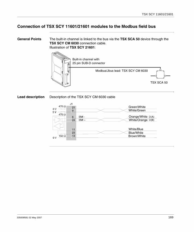
TSX SCY 11601/21601
Connection of TSX SCY 11601/21601 modules to the Modbus field bus
General Points The built-in channel is linked to the bus via the TSX SCA 50 device through the TSX SCY CM 6030 connection cable. Illustration of TSX SCY 21601:
Lead description Description of the TSX SCY CM 6030 cable
Built-in channel with25 pin SUB-D connector
Modbus/Jbus lead: TSX SCY CM 6030
TSX SCA 50
Green/WhiteWhite/Green
Orange/WhiteWhite/Orange
White/BlueBlue/WhiteBrown/White
335009581 02 May 2007 169

TSX SCY 11601/21601
Reminder on single line polarization in RS 485
General Single line polarization is the polarization used for Modbus type networks. General architecture diagram of a RS 485 network:
The senders are symbolized by:
The receivers are symbolized by:
170 335009581 02 May 2007

TSX SCY 11601/21601
Connection of network stations
The network is made up of one shielded twisted pair. The different stations of the network are connected as follows:
Integral Characteristics
Integral characteristics are:Up to 32 stationsMaximum range: about 1,300 mBus Topology ≤ 15 m Branching 2 wire half duplexLine end adaptation at the end stationsAdaptation of distributed line Rp = 470 Ω
1 Link all outputs labeled + (Tx+, Rx+) to the network wire labeled: L+.
2 Link all outputs labeled - (Tx-, Rx-) to the network wire labeled: L-
3 Adapt the impedance of the network to the average of the two adaptation elements (Rc) located on the two end stations of the network.
4 For distributed polarization of the network, connect the wire L+ to 5 V and the wire L- to 0 V via the two polarization resistors (Rp = 470 Ω). This polarization continuously circulates a current in the network.The adaptation can be made anywhere in the network (in practice it is generally made at master level).There must be single polarization for the entire network, whatever its range.
335009581 02 May 2007 171

TSX SCY 11601/21601
Example of Modbus architecture
Example
172 335009581 02 May 2007
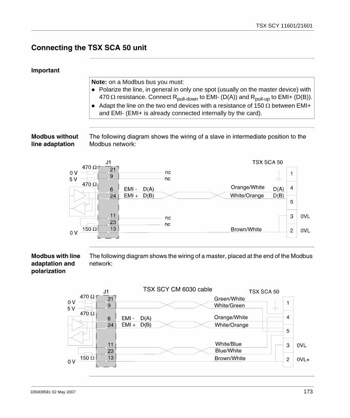
TSX SCY 11601/21601
Connecting the TSX SCA 50 unit
Important
Modbus without line adaptation
The following diagram shows the wiring of a slave in intermediate position to the Modbus network:
Modbus with line adaptation and polarization
The following diagram shows the wiring of a master, placed at the end of the Modbus network:
Note: on a Modbus bus you must:Polarize the line, in general in only one spot (usually on the master device) with 470 Ω resistance. Connect Rpull-down to EMI- (D(A)) and Rpull-up to EMI+ (D(B)).Adapt the line on the two end devices with a resistance of 150 Ω between EMI+ and EMI- (EMI+ is already connected internally by the card).
TSX SCY CM 6030 cable
Orange/White
White/Orange
Brown/White
TSX SCY CM 6030 cable
Green/WhiteWhite/Green
Orange/WhiteWhite/Orange
White/BlueBlue/WhiteBrown/White
335009581 02 May 2007 173

TSX SCY 11601/21601
Character Mode connection for TSX SCY 21601
General The TSX SCY CM 6030 cable should be used to connect the TSX SCY 21601 module with an RS 485 standard device.
Users should connect the Character Mode TSX SCY 21601 to a Half duplex RS 485 standard device using the TSX SCY CM 6030 connection cable, adding a connector adapted for the intended device to the end of the cable, and linking the necessary signals (see lead connection in Connecting the TSX SCA 50 unit, p. 173).
Illustration:
Two wireRS 485 device
TSX SCY CM 6030 Cable
174 335009581 02 May 2007

TSX SCY 11601/21601
Consumption of TSX SCY 11601/21601 modules
Values This table shows the consumption of TSX SCY 11601 and TSX SCY 21601 modules without a PCMCIA card (for 21601) or connection to the built-in channel:
Voltage Typical Current Maximum Current Power dissipation
5 Volts 350 mA 420 mA 2.1 W max.
335009581 02 May 2007 175

TSX SCY 11601/21601
176 335009581 02 May 2007
335009581 02 May 2007
8
Installing PCMCIA cardsAt a Glance
Aim of this Chapter
This Chapter deals with the hardware installation of PCMCIA communication cards onto Premium/Atrium PLCs.
What's in this Chapter?
This chapter contains the following sections:
Section Topic Page
8.1 At a Glance 178
8.2 Description 181
8.3 Connecting the PCMCIA card reception channel 183
8.4 Connection of TSX SCP 111 card 193
8.5 Connection of the TSX SCP 112 card 196
8.6 Connection of the TSX SCP 114 card 208
8.7 Connection of the TSX FPP 20 card 217
8.8 Connection of the TSX FPP 10 card 218
8.9 Connection of the TSX MBP 100 card 219
8.10 Summary of connection devices 227
8.11 Precautions when connecting PCMCIA cards 229
8.12 Consumption of PCMCIA cards 230
177

PCMCIA installation
8.1 At a Glance
At a Glance
General Premium/Atrium PLC stations connect to communication networks, buses and links through PCMCIA communication cards.The card to be connected is a metal device whose dimensions comply with PCMCIA extended type III.PCMCIA cards are installed in the reception slot of the processor and/or TSX SCY 21601 module in PLCs from the Premium family.PCMCIA cards can also be used in devices which have type III reception, such as CCX 17, FT 2100 terminals or PC-compatible third-party devices, for example.
Illustration:
PCMCIA cards are installed, operated and maintained using PL7 Junior/PL7 Pro programming and operation software for all PLCs in the Premium family.
Note: It is prohibited to connect PCMCIA cards when the power is switched on.
Micro
Premium
Premium
Atrium
178 335009581 02 May 2007

PCMCIA installation
TSX SCP 11 cards
Series link PCMCIA cards.
Each TSX SCP 111, 112, 114 PCMCIA card supports a different physical layer. This family comprises three products:
All three cards, TSX SCP 111, 112 and 114, support the following communication protocols:
Modbus/Jbus protocolUNI-TELWAY protocolCharacter Mode asynchronous link
TSX FFP 20 card FIPWAY network PCMCIA card:
Product reference Physical layer Illustration
TSX SCP 111 RS 232 link.
TSX SCP 112 Current loop link (20 mA).
TSX SCP 114 RS 485 link (RS 422 compatible)
Functions Illustration
The TSX FPP 20 PCMCIA card supports the FIP physical layer. It is used to connect a Premium/Atrium station to a FIPWAY network, as well as to connect to devices of manufacturers who wish to connect their products to the FIPWAY network.The card is fitted with four rotary switches (marked "1" in the illustration) which make it possible to encode the network number and station.
335009581 02 May 2007 179

PCMCIA installation
TSX MBP 100 card
Modbus + network PCMCIA card:
TSX FPP 10 card FIPIO bus agent PCMCIA card:
Functions Illustration
The TSX MBP 100 PCMCIA card is used to connect a Premium/Atrium PLC station to the Modbus+ network.
Functions Illustration
The TSX FPP 10 PCMCIA card is used to connect a Premium/Atrium PLC station to a FIPIO bus.It ensures the link with TSX 47-107 PLCs and April 5000
180 335009581 02 May 2007

PCMCIA installation
8.2 Description
Description
General PCMCIA type III (extended) communication cards are built into a metal device with the following dimensions:
Length: 85.5 mm,Width: 51 mm,Height: 10 mm.
The front of the card is designed to display the functioning of communications as well as the physical connection to the network.
Mechanical configuration
The mechanical configuration of the card must be adapted by mounting a removable cover, depending on the type of installation desired:
Type of installation Configuration Illustration
Installation on a Premium type processor or on a TSX SCY 21601 communication module.
Removable cover with wings. Screws are provided to fix it to the reception module (marked 3 on illustration)
Installation on an Atrium type processor.
Removable cover with wings. Screws are provided to fix it to the Atrium processor (marked 2 on illustration).
Installation onto a PC compatible device.
Removable cover (marked 1 on illustration).
Note: The covers with wings, mounted on PCMCIA cards, prevent any accidental removal when switched on and guarantee that the card remains in good working order.The two covers (1) and (3) are provided with the PCMCIA card. Cover (2) is provided with the Atrium processor.
335009581 02 May 2007 181

PCMCIA installation
Connection to the network is achieved by connecting the linking cable to the front of the card. A guidance system is used to prevent anything being mounted incorrectly.The product reference label informs the user of the type of physical layer supported by the card.
182 335009581 02 May 2007

PCMCIA installation
8.3 Connecting the PCMCIA card reception channel
At a Glance
Aim of this Section
This Section describes the installation of PCMCIA cards in the reception channel of the TSX SCY 21601 module.
What's in this Section?
This section contains the following topics:
Topic Page
Precautions when connecting PCMCIA 184
Connecting PCMCIA cards 185
Product references for PCMCIA cards and installation 186
Mounting cards and cables 187
PCMCIA card operation display 189
Visual diagnostics of PCMCIA cards 190
335009581 02 May 2007 183
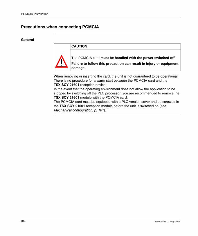
PCMCIA installation
Precautions when connecting PCMCIA
General
When removing or inserting the card, the unit is not guaranteed to be operational. There is no procedure for a warm start between the PCMCIA card and the TSX SCY 21601 reception device.In the event that the operating environment does not allow the application to be stopped by switching off the PLC processor, you are recommended to remove the TSX SCY 21601 module with the PCMCIA card.The PCMCIA card must be equipped with a PLC version cover and be screwed in the TSX SCY 21601 reception module before the unit is switched on (see Mechanical configuration, p. 181).
CAUTION
The PCMCIA card must be handled with the power switched offFailure to follow this precaution can result in injury or equipment damage.
184 335009581 02 May 2007

PCMCIA installation
Connecting PCMCIA cards
General Connecting PCMCIA cards requires specific cables and connection devices, depending on the type of models.
Series link cards Product references of cables and branch devices to be used with series link PCMCIA cards according to the different protocols:
FIPWAY network card
The TSX FPP 20 FIPWAY card is connected via the reception channel using a TSX FPCG 10 or TSX FPCG 30 cable.
Modbus+ Card The TSX MBP 100 Modbus+ card is connected via the reception channel using a TSX MBP CE 030 (3 m) or TSX MBP CE 060 (6 m).
PCMCIA card UNI-TELWAY Jbus/Modbus Character Mode
TSX SCP 111 (RS 232)
TSX SCP CD 1030/1100 in point to point mode
TSX SCP CD 1030/1100 in point to point mode
TSX SCP CD 1030/1100
TSX SCP CC 1030 in multidrop mode via a modem
TSX SCP CC 1030 in multidrop mode via a modem
TSX SCP 112 (Current Loop
TSX SCP CX 2030 TSX SCP CX 2030 TSX SCP CX 2030
TSX SCP 114 (RS 422/RS 485
TSX SCP CU 4030 and TSX SCA 50
TSX SCP CM 4030 and TSX SCA 50
TSX SCP CU 4030 and TSX SCP CM 4030
335009581 02 May 2007 185

PCMCIA installation
Product references for PCMCIA cards and installation
Installation Table showing options for installing PCMCIA cards in processor reception channels and in the TSX SCY 21601 module:
Application-specific channels and network connections
Table showing the number of application-specific channels or network connections used by PCMCIA cards:
Reminder of the number of application-specific channels and network connections managed by the type of processor:
Product references Processor reception channel TSX SCY 21601 reception channel
TSX SCP 111 Yes Yes
TSX SCP 112 Yes Yes
TSX SCP 114 Yes Yes
TSX FPP 10 Yes No
TSX FPP 20 Yes Yes
TSX MBP 100 Yes No
Product references Number of application-specific channels Number of Network Connections
Card in the processor Card in the TSX SCY 21601 module
TSX SCP 111 0 1 -
TSX SCP 112 0 1 -
TSX SCP 114 0 1 -
TSX FPP 10 0 - -
TSX FPP 20 - - 1
TSX MBP 100 - - 1
Processors Application-specific channels
Network connections
TSX P57103/TSX P57153 8 2
TSX P57203 / TSX P57253 / TSX P572623 / TSX P572823 - PCX 57203
24 4
TSX P303 / TSX P57353/ TSX P573623 - PCX 57353
32 8
TSX P57453 / TSX P574823 64 8
186 335009581 02 May 2007

PCMCIA installation
Mounting cards and cables
Details about PCMCIA cards
Illustration:
PCMCIA cards are made up of the following elements:
Number Designation Comments
1 Equipped card Receives electronic components.
2 Body made of zamac -
3 PCMCIA connector Connector with 20 connection points.
4 Upper cover Houses the product reference label which shows the type of PCMCIA card
5 Removable cover Ensures the card is displayed in its slot. The names of the two LEDs are printed on the front of the removable cover. This cover is also used to fix the PCMCIA card on the processor or on the TSX SCY 21601 module.
6 Linking cable with ferule The ferule placed on the end of the PCMCIA card cable side prevents the cable being pinched by the removable cover. This ferule also eliminates the risk of causing a bending radius which can damage the quality of the link.
335009581 02 May 2007 187
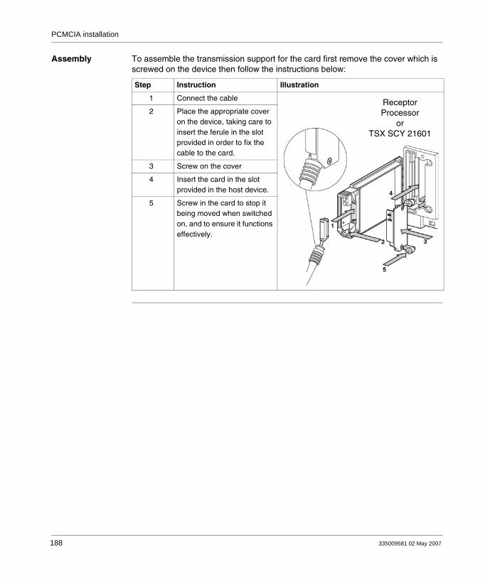
PCMCIA installation
Assembly To assemble the transmission support for the card first remove the cover which is screwed on the device then follow the instructions below:
Step Instruction Illustration
1 Connect the cable
2 Place the appropriate cover on the device, taking care to insert the ferule in the slot provided in order to fix the cable to the card.
3 Screw on the cover
4 Insert the card in the slot provided in the host device.
5 Screw in the card to stop it being moved when switched on, and to ensure it functions effectively.
ReceptorProcessor
orTSX SCY 21601
188 335009581 02 May 2007

PCMCIA installation
PCMCIA card operation display
General Two diagnostics LEDs are located on the front of the card. They inform the user on how exchanges between the device supporting the PCMCIA card and the related device are functioning.
Illustration
Number Description Diagram
1 Error "ERR" LED (normally off) displays errors.This is red
2 The "COM" communication LED displays the line activity.This LED is:
Yellow on the TSX SCP 111-112-114, TSX FPP 10 and TSX FPP 20 cards.Green on the TSX MBP 100 card.
335009581 02 May 2007 189
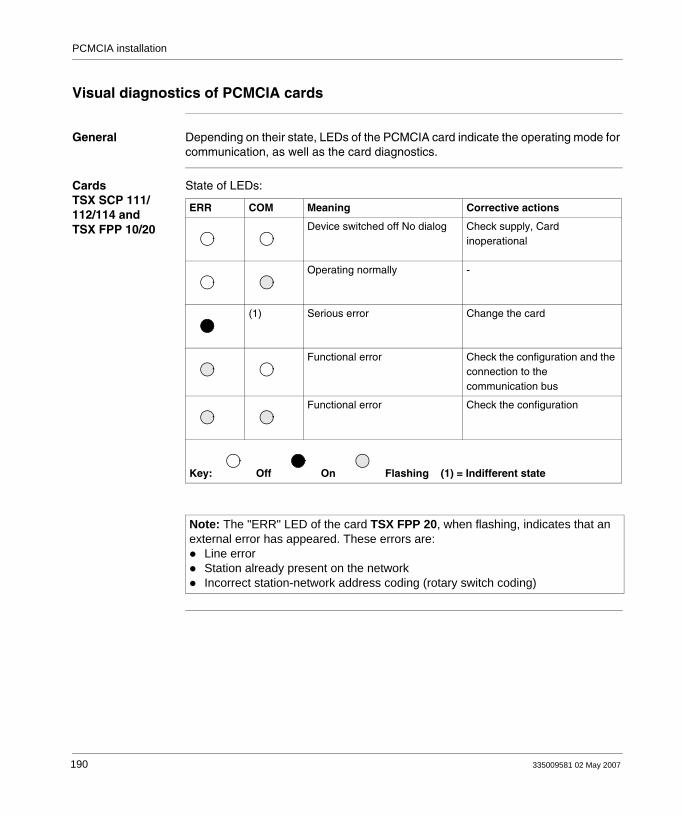
PCMCIA installation
Visual diagnostics of PCMCIA cards
General Depending on their state, LEDs of the PCMCIA card indicate the operating mode for communication, as well as the card diagnostics.
Cards TSX SCP 111/112/114 and TSX FPP 10/20
State of LEDs:
ERR COM Meaning Corrective actions
Device switched off No dialog Check supply, Card inoperational
Operating normally -
(1) Serious error Change the card
Functional error Check the configuration and the connection to the communication bus
Functional error Check the configuration
Key: Off On Flashing (1) = Indifferent state
Note: The "ERR" LED of the card TSX FPP 20, when flashing, indicates that an external error has appeared. These errors are:
Line errorStation already present on the networkIncorrect station-network address coding (rotary switch coding)
190 335009581 02 May 2007

PCMCIA installation
TSX MBP 100 cards
State of LEDs:
Meaning of COM LED flashing:
ERR COM Meaning Corrective actions
Device switched off No dialog Check supply, Card inoperational
(1)
Operating normally -
(2) Serious error Change the card
Functional error: Card not configured, communication cannot start on the network.
Configure the card using: PL7 Junior or PL7 Pro
Functional error Check the configuration and the connection to the Modbus+ network. The way the COM LED flashes indicates the type of problem (see below)
Off On Flashing (1) = The way the COM LED flashes indicates the operating state of the network (see below) - (2) = Indifferent state
State of COM LED Meaning
6 flashes/second Node is functioning normally It receives and transmits the network token. All the nodes on a network which are functioning flash in this way.
1 flash/second The node is off-line just after power up or after leaving the 4 flashes/sec. mode. In this state, the node monitors the network and establishes a table of active nodes. After remaining in this state for 5 seconds, the node attempts to switch to a normal operating state, indicated by 6 flashes per second.
2 flashes, followed by a 2 second pause
The node detects the token transmitted among the other nodes, but never receives the token. Check if there is an open circuit or a faulty terminator on the network.
335009581 02 May 2007 191

PCMCIA installation
3 flashes, followed by a 1.7 second pause
The node does not detect any token transmitted among the other nodes. It regularly searches for the token but cannot find another node to pass the token to it. Check if there is an open circuit or a faulty terminator on the network.
4 flashes, followed by a 1.4 second pause
The node has detected a valid node message using a network address identical to its own address. The node remains in this state for as long as it continues to detect the duplicated address. If the duplicated address has not been detected within 5 seconds, the node changes mode and flashes once per second.
State of COM LED Meaning
192 335009581 02 May 2007

PCMCIA installation
8.4 Connection of TSX SCP 111 card
At a Glance
Aim of this Section
This Section deals with installing hardware for TSX SCP 111 PCMCIA cards.
What's in this Section?
This section contains the following topics:
Topic Page
Point to point connection in Character Mode (DTE <==> DTE) 194
Uni-Telway, Modbus or Character Mode via Modem 195
335009581 02 May 2007 193

PCMCIA installation
Point to point connection in Character Mode (DTE <==> DTE)
General The TSX SCP 111 RS 232 physical support card is inserted either in the processor or in the TSX SCY 21601 module. It is connected to the related device with the TSX SCP CD 1030/1100 cable.The devices to be connected are DTE to DTE (Data Terminal Equipment ). For example: terminal, printer, etc.Illustration:
Description of TSX SCP CD 1030 cable
Illustration:
TSX SCP CD 1030 (length 3 m)
or TSX SCP CD 1100 (length 10 m)
TSX SCP 111 Printer
The PCMCIA 20-pin mini-connectorsupports the signals:
White/blue ringsBlue/white rings
White/orange ringsOrange/white rings
Green/white ringsWhite/green rings
194 335009581 02 May 2007
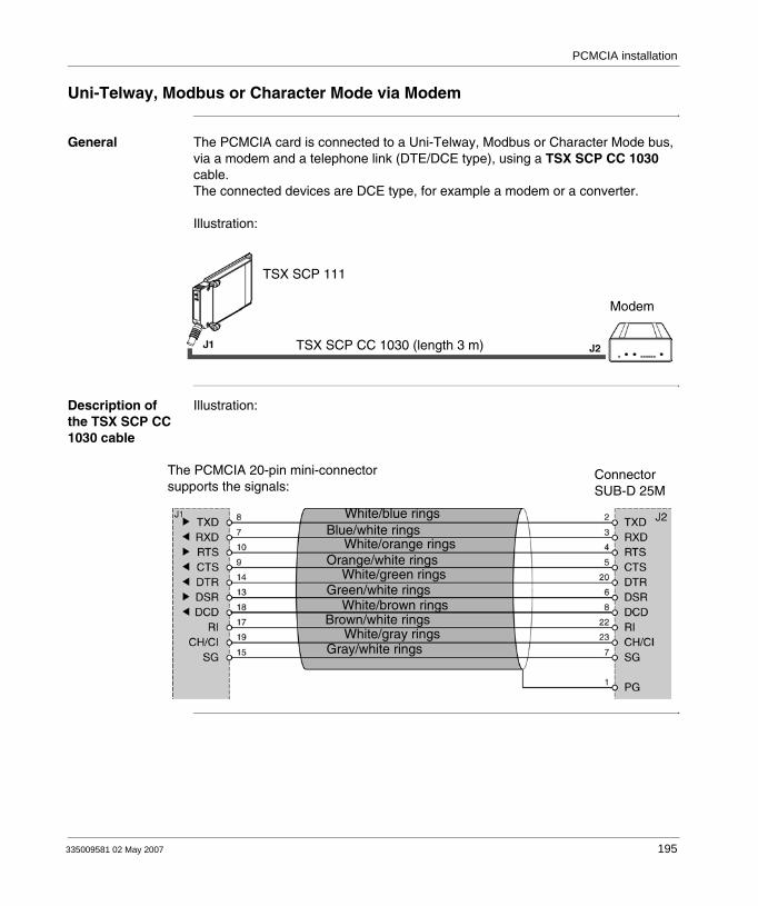
PCMCIA installation
Uni-Telway, Modbus or Character Mode via Modem
General The PCMCIA card is connected to a Uni-Telway, Modbus or Character Mode bus, via a modem and a telephone link (DTE/DCE type), using a TSX SCP CC 1030 cable.The connected devices are DCE type, for example a modem or a converter.
Illustration:
Description of the TSX SCP CC 1030 cable
Illustration:
TSX SCP CC 1030 (length 3 m)
TSX SCP 111
Modem
The PCMCIA 20-pin mini-connectorsupports the signals:
ConnectorSUB-D 25M
White/blue ringsBlue/white rings
White/orange ringsOrange/white rings
Green/white ringsWhite/green rings
White/brown rings
White/gray ringsBrown/white rings
Gray/white rings
335009581 02 May 2007 195
PCMCIA installation
8.5 Connection of the TSX SCP 112 card
At a Glance
Aim of this Section
This Section deals with the hardware installation for TSX SCP 112 PCMCIA cards.
What's in this Section?
This section contains the following topics:
Topic Page
Connection of the TSX SCP 112 card 197
Connecting in point to point mode 198
Multidrop connection 199
Dynamic performance 200
TSX SCP 112 connection with April 5000/7000 PLCs 202
196 335009581 02 May 2007

PCMCIA installation
Connection of the TSX SCP 112 card
General The PCMCIA TSX SCP 112 card is used to connect a Premium/Atrium PLC station to a loop link with a current of 20 mA in point to point or multidrop.
The TSX SCP CX 2030 cable is used for this type of connection (length 3 m).
Description of the TSX SCP CX 2030 cable:
Note: In all cases the power supply is: 24 V ± 20%, external to the TSX SCP 112 card, and must provide the current required for the current loop supply .
Note: A screw terminal block needs to be installed to connect the TSX SCP 112 card.
Orange/White
White/Blue
White/Green
Green/White
White/Orange
Blue/White
The PCMCIA 20-pin mini-connectorsupports the signals:
9
13
19
17
2
J1
20
+ Alim
EMI mlp
+ REC
- REC
EMI pap
- Alim
335009581 02 May 2007 197

PCMCIA installation
Connecting in point to point mode
General The diagram below describes the wiring principles for TSX SCP 112 loop current PCMCIA cards in point to point. Point to point is only carried out according to 20 mA mode when idle.Illustration:
Gre
en/W
hite
Whi
te/G
reen
Whi
te/B
lue
Whi
te/O
rang
e
Blu
e/W
hite
Gre
en/W
hite
Whi
te/G
reen
Whi
te/B
lue
Whi
te/O
rang
e
Blu
e/W
hite
Station 1SCP 112
Station 2SCP 112
Junction block 1 Junction block 2
9
19
17
2
20
9
19
17
2
20
24 V+-
Note: Important: the cable shielding must be connected at the shortest point in the junction blocks.
198 335009581 02 May 2007

PCMCIA installation
Multidrop connection
General Multidrop is only carried out in 0 mA idle mode. The send cable and receive cable are set in parallel. The master is set by the software. Example of connection of n TSX SCP 112 cards:
Station 1TSX SCP 112
Station 2TSX SCP 112
Station 3TSX SCP 112
Gre
en/W
hite
Whi
te/B
lue
Whi
te/G
reen
Ora
nge/
Whi
te
Gre
en/W
hite
Whi
te/B
lue
Whi
te/G
reen
Ora
nge/
Whi
te
Gre
en/W
hite
Whi
te/B
lue
Whi
te/G
reen
Ora
nge/
Whi
te
Rc
Junction block 1 Junction block 2Rc = resistance of optional load
Junction block n
Note: Important: the cable shielding must be connected at the shortest point in the junction blocks.
335009581 02 May 2007 199

PCMCIA installation
Dynamic performance
General The flow of a current loop link is limited by the cross-section and the length or the cable used.The user should refer to the two charts below to evaluate the performance which can be obtained using this application.
Point to point These curves are given for a shielded two pair cable (send through one pair, reception through the other) while observing all the precautions of use.
Multidrop The chart below is given for a shielded cable with a conductor cross-section of
0.34 mm2. The connection is made according to the parallel multidrop diagram below. Using conductors with a larger cross-section improves the quality of the signals transmitted:
Multidrop link performance is optimized when there are more connected stations. The line is busier, which improves the quality of the transmitted signal.
cable 1 mm2 4500 m max.
cable 0.64 mm2 2500 m max.
cable 0.34 mm2 1300 m max.
speed in Kbps
Number of connected stations
200 335009581 02 May 2007
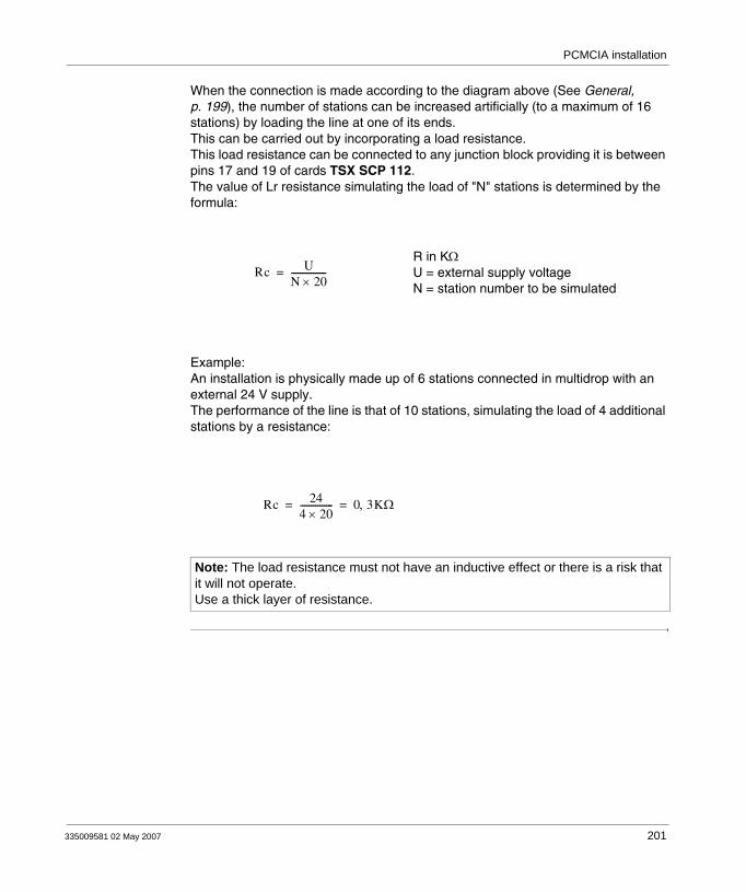
PCMCIA installation
When the connection is made according to the diagram above (See General, p. 199), the number of stations can be increased artificially (to a maximum of 16 stations) by loading the line at one of its ends.This can be carried out by incorporating a load resistance.This load resistance can be connected to any junction block providing it is between pins 17 and 19 of cards TSX SCP 112.The value of Lr resistance simulating the load of "N" stations is determined by the formula:
Example:An installation is physically made up of 6 stations connected in multidrop with an external 24 V supply.The performance of the line is that of 10 stations, simulating the load of 4 additional stations by a resistance:
Note: The load resistance must not have an inductive effect or there is a risk that it will not operate. Use a thick layer of resistance.
Rc UN 20×----------------=
R in KΩU = external supply voltageN = station number to be simulated
Rc 244 20×--------------- 0 3KΩ,= =
335009581 02 May 2007 201
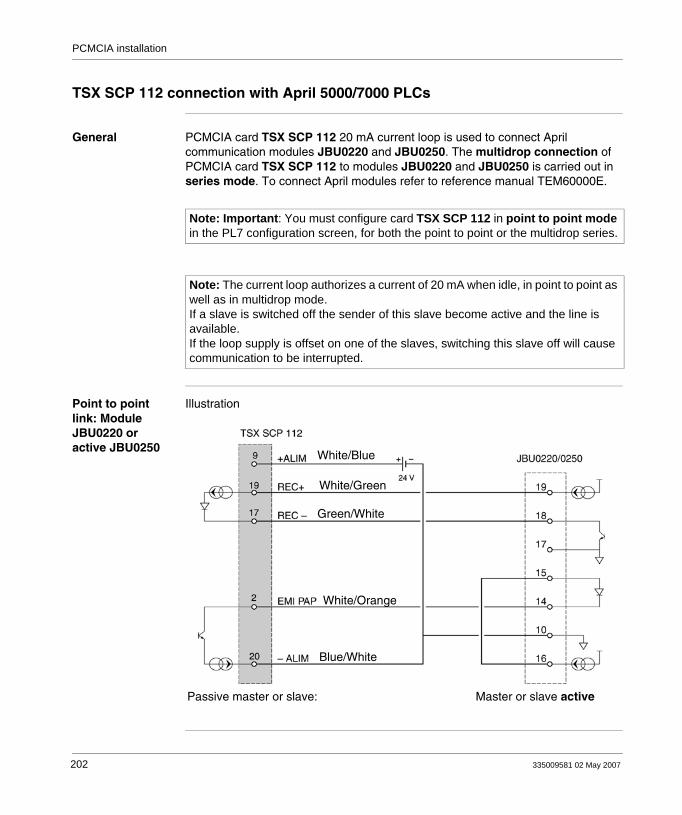
PCMCIA installation
TSX SCP 112 connection with April 5000/7000 PLCs
General PCMCIA card TSX SCP 112 20 mA current loop is used to connect April communication modules JBU0220 and JBU0250. The multidrop connection of PCMCIA card TSX SCP 112 to modules JBU0220 and JBU0250 is carried out in series mode. To connect April modules refer to reference manual TEM60000E.
Point to point link: Module JBU0220 or active JBU0250
Illustration
Note: Important: You must configure card TSX SCP 112 in point to point mode in the PL7 configuration screen, for both the point to point or the multidrop series.
Note: The current loop authorizes a current of 20 mA when idle, in point to point as well as in multidrop mode.If a slave is switched off the sender of this slave become active and the line is available.If the loop supply is offset on one of the slaves, switching this slave off will cause communication to be interrupted.
White/Blue
White/Green
Green/White
White/Orange
Blue/White
Passive master or slave: Master or slave active
202 335009581 02 May 2007

PCMCIA installation
Point to point link: active TSX SCP 112 card
Illustration:
Mixed terminal links
Illustration:
White/Blue
White/Green
Green/White
White/Orange
Blue/White
Master or slave active Master or slave passive
White/Blue
White/Green
Green/White
White/Orange
Blue/White
Master or slave:passive receivingactive sending
Master or slave:passive receivingactive sending
335009581 02 May 2007 203

PCMCIA installation
Multidrop type link
The following examples describe the different wiring possibilities for card TSX SCP 112 with modules JBU0220/0250.
Example 1: Active master TSX SCP 112 multidrop
Note: Important: The 24 V supply of each TSX SCP 112 present on the loop must be connected, whether passively or actively, otherwise the link will not function.These supplies must not have any shared (potential) point between them. Do not connect the -24 V supply to the earth.
White/Blue
White/Green
Green/White
White/Orange
Blue/White
Master active
Slave 2 passive
Slave 1 passive
204 335009581 02 May 2007
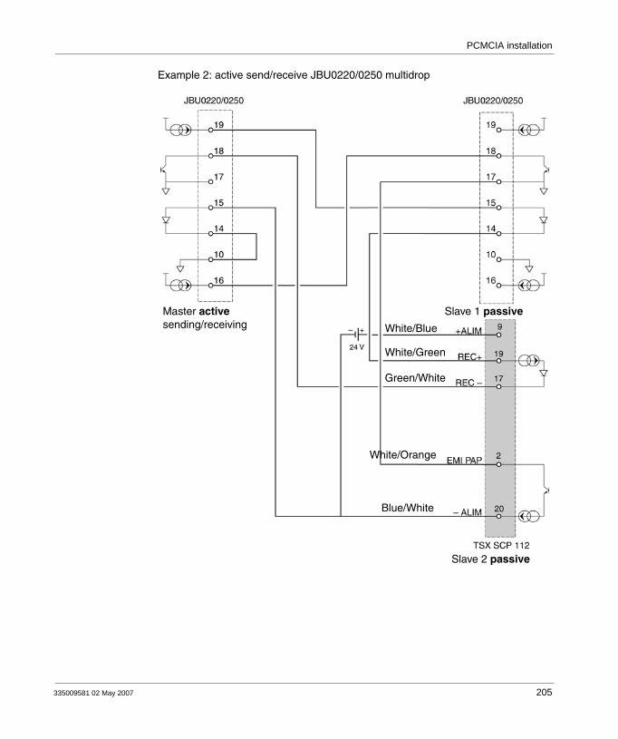
PCMCIA installation
Example 2: active send/receive JBU0220/0250 multidrop
White/Blue
White/Green
Green/White
White/Orange
Blue/White
Master activesending/receiving
Slave 2 passive
Slave 1 passive
335009581 02 May 2007 205

PCMCIA installation
Example 3: Multidrop master JBU0220/0250 active send/receive - slaves TSX SCP 112
White/Blue
White/Green
Green/White
White/Orange
Blue/White
Master activesending/receiving
Slave 2 passive
Slave 1 passive
White/Blue
White/Green
Green/White
White/Orange
Blue/White
206 335009581 02 May 2007

PCMCIA installation
Example 4: Multidrop active master TSX SCP 112
Green/White
White/Orange
Blue/White
Master activesending/receiving
Slave 2 passive
Slave 1 passive
White/Blue
White/Green
Green/White
White/Orange
Blue/White
White/Green
White/Blue
335009581 02 May 2007 207
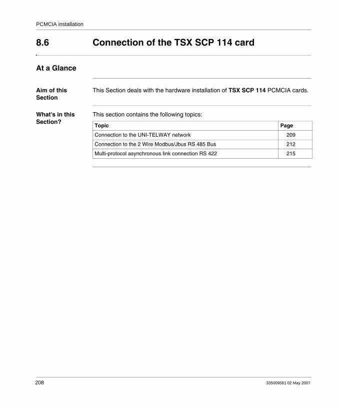
PCMCIA installation
8.6 Connection of the TSX SCP 114 card
At a Glance
Aim of this Section
This Section deals with the hardware installation of TSX SCP 114 PCMCIA cards.
What's in this Section?
This section contains the following topics:
Topic Page
Connection to the UNI-TELWAY network 209
Connection to the 2 Wire Modbus/Jbus RS 485 Bus 212
Multi-protocol asynchronous link connection RS 422 215
208 335009581 02 May 2007

PCMCIA installation
Connection to the UNI-TELWAY network
General Card TSX SCP 114, physical support RS 485, connects to the UNI-TELWAY network using cable TSX SCP CU 4030 via the connection device TSX SCA 50, or by cable TSX SCP CU 4530 (provided with SUB-D 15 pin connector) via device TSX SCA 62. The card is inserted in the processor or in module TSX SCY 21601.
The TSX SCA 50 is passive and made up of a printed circuit board fitted with 3 sets of screw terminal blocks. It is used to connect a station by branching on the main section of a UNI-TELWAY bus.It ensures continuing operation of electrical signals, shielding and end of line adaptation function.
Type of connection
The cable of the PCMCIA card has bare wires at its ends which the user must connect to the terminal located inside the device.Illustration:
TSX SCP CU 4030
TSX SCP 114
Note: The branching device configures the wiring system of the card and a branching type of connection system.
335009581 02 May 2007 209

PCMCIA installation
Description of the TSX SCP CU 4030 cable
Illustration:
Connection via a TSX SCA 62 device
Illustration:
TSX SCA 50 deviceThe PCMCIA 20-pin mini-connectorsupports the signals:
RedWhite
WhiteBlue
TSX SCP CU 4530
TSX SCP 114
210 335009581 02 May 2007

PCMCIA installation
Description of the TSX SCP CU 4530 cable
Illustration:
TSX SCA 62 device
The PCMCIA 20-pin mini-connectorsupports the signals:
RedWhite
WhiteBlue
15-pin SUB-D
Ω
Ω
335009581 02 May 2007 211

PCMCIA installation
Connection to the 2 Wire Modbus/Jbus RS 485 Bus
General The TSX SCP 114 PCMCIA card is connected to the Modbus bus using the TSX SCP CM 4030 link cable. This cable is connected to the TSX SCA 50 branching device.
Type of Connection
The cable of the PCMCIA card has bare wires at its ends which the user must connect to the terminal located inside the device.
TSX SCP CM 4030
TSX SCP 114
Note: The length of the cable used (3 m), makes it possible to link a device to a TSX SCA 50 connection device located within a 3 meter radius of the card. This length ensures connection inside a standard cabinet
212 335009581 02 May 2007
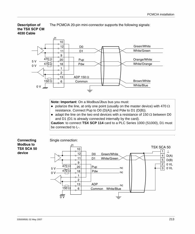
PCMCIA installation
Description of the TSX SCP CM 4030 Cable
The PCMCIA 20-pin mini-connector supports the following signals:
Connecting Modbus to TSX SCA 50 device
Single connection:
150 Ω
Green/White
White/Green
Orange/White
Brown/White
White/Orange
D0D1
PupPdw
ADP 150 ΩCommon
White/Blue
470 Ω
470 Ω5 V0 V
0 V
J110
12
119
201812
136
Note: Important: On a Modbus/Jbus bus you must:polarize the line, at only one point (usually on the master device) with 470 Ω resistance. Connect Pup to D0 (D(A)) and Pdw to D1 (D(B)).adapt the line on the two end devices with a resistance of 150 Ω between D0 and D1 (D1 is already connected internally by the card).
Caution: to connect TSX SCP 114 card to a PLC Series 1000 (S1000), D1 must be connected to L-.
TSX SCA 50
150 Ω
Green/WhiteWhite/Green
D0D1
PupPdw
ADP
Common White/Blue
470 Ω
470 Ω5 V0 V
0 V
J110
12
119
201812
136
ncnc
nc
14523
D(A)
0 VL
D(B)0 VL
335009581 02 May 2007 213

PCMCIA installation
Connection with line polarization:
Connection with line adaptation:
Connection with line polarization and adaptation:
TSX SCA 50
150 Ω
Green/WhiteWhite/Green
D0D1
PupPdw
ADP
Common White/Blue
470 Ω
470 Ω5 V0 V
0 V
J110
12
119
201812
136
14523
D(A)
0 VL
D(B)0 VL
Orange/WhiteWhite/Orange
nc
TSX SCA 50
150 Ω
Green/WhiteWhite/Green
D0D1
PupPdw
ADP
Common White/Blue
470 Ω
470 Ω5 V0 V
0 V
J110
12
119
201812
136
14523
D(A)
0 VL
D(B)0 VL
Brown/White
ncnc
TSX SCA 50
150 Ω
Green/WhiteWhite/Green
D0D1
PupPdw
ADP
Common White/Blue
470 Ω
470 Ω5 V0 V
0 V
J110
12
119
201812
136
14523
D(A)
0 VL
D(B)0 VL
Orange/WhiteWhite/Orange
Brown/White
214 335009581 02 May 2007
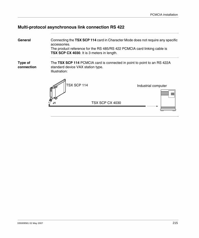
PCMCIA installation
Multi-protocol asynchronous link connection RS 422
General Connecting the TSX SCP 114 card in Character Mode does not require any specific accessories.The product reference for the RS 485/RS 422 PCMCIA card linking cable is TSX SCP CX 4030. It is 3 meters in length.
Type of connection
The TSX SCP 114 PCMCIA card is connected in point to point to an RS 422A standard device VAX station type.Illustration:
TSX SCP CX 4030
TSX SCP 114 Industrial computer
335009581 02 May 2007 215

PCMCIA installation
Description of the TSX SCP CX 4030 cable
Illustration:
See also Character Mode connection for TSX SCY 21601, p. 174 (TSX SCY 21601 module integrated link)
The PCMCIA 20-pin mini-connectorsupports the signals:
White/Green
Orange/White
White/Orange
Brown/White
Green/WhiteEMI -
18
10
12
11
GND
VCC
J1470 Ω
9
470 Ω
100
Ω10
0 Ω
20
1
2
5
13
16
4
EMI +
REC -
REC +
ADP Rec
ADP 150r
0 V iso
216 335009581 02 May 2007
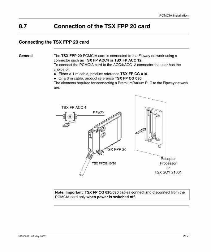
PCMCIA installation
8.7 Connection of the TSX FPP 20 card
Connecting the TSX FPP 20 card
General The TSX FPP 20 PCMCIA card is connected to the Fipway network using a connector such as TSX FP ACC4 or TSX FP ACC 12.To connect the PCMCIA card to the ACC4/ACC12 connector the user has the choice of:
Either a 1 m cable, product reference TSX FP CG 010.Or a 3 m cable, product reference TSX FP CG 030.
The elements required for connecting a Premium/Atrium PLC to the Fipway network are:
Note: Important: TSX FP CG 010/030 cables connect and disconnect from the PCMCIA card only when power is switched off.
TSX FP ACC 4
TSX FPP 20
ReceptorProcessor
orTSX SCY 21601
335009581 02 May 2007 217
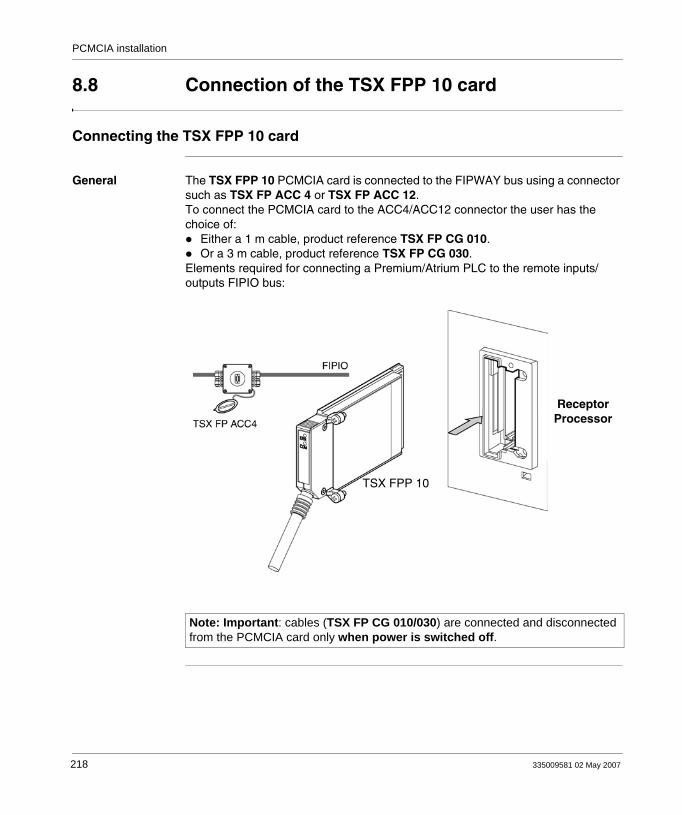
PCMCIA installation
8.8 Connection of the TSX FPP 10 card
Connecting the TSX FPP 10 card
General The TSX FPP 10 PCMCIA card is connected to the FIPWAY bus using a connector such as TSX FP ACC 4 or TSX FP ACC 12.To connect the PCMCIA card to the ACC4/ACC12 connector the user has the choice of:
Either a 1 m cable, product reference TSX FP CG 010.Or a 3 m cable, product reference TSX FP CG 030.
Elements required for connecting a Premium/Atrium PLC to the remote inputs/outputs FIPIO bus:
Note: Important: cables (TSX FP CG 010/030) are connected and disconnected from the PCMCIA card only when power is switched off.
ReceptorProcessor
TSX FPP 10
218 335009581 02 May 2007
PCMCIA installation
8.9 Connection of the TSX MBP 100 card
At a Glance
Aim of this Section
This Section deals with the hardware installation of TSX MBP 100 PCMCIA Modbus Plus cards.
What's in this Section?
This section contains the following topics:
Topic Page
Connecting the TSX MBP100 card 220
General principle for connecting the PCMCIA card 221
Grounding the TSX MBP CE 030/060 cable 222
Connecting the TSX MBP CE 030/060 cable to Modicon connection device 990 NAD 230 00
224
335009581 02 May 2007 219

PCMCIA installation
Connecting the TSX MBP100 card
General The TSX MBP 100 PCMCIA card is connected to the Modbus Plus network using the TSX MBP CE 030 branch cable, 3 m long, or the TSX MBP CE 060, 3 m long. This cable is connected to Modicon branch device (local site tap) 990NA23000. For information on how to install a Modbus Plus network, see the Modicon Manual "Modbus Plus Network-Installation and Planning Manual" Product Reference 890 USE 100 01".
220 335009581 02 May 2007
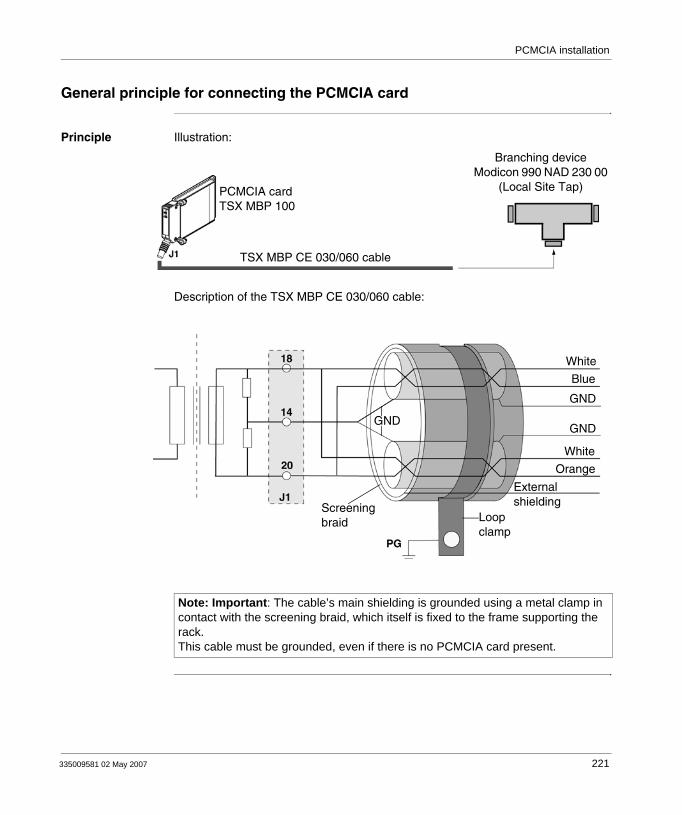
PCMCIA installation
General principle for connecting the PCMCIA card
Principle Illustration:
Description of the TSX MBP CE 030/060 cable:
Branching deviceModicon 990 NAD 230 00
(Local Site Tap)PCMCIA cardTSX MBP 100
TSX MBP CE 030/060 cable
GND
Screeningbraid Loop
clamp
Externalshielding
Orange
White
GND
GND
Blue
White
Note: Important: The cable’s main shielding is grounded using a metal clamp in contact with the screening braid, which itself is fixed to the frame supporting the rack.This cable must be grounded, even if there is no PCMCIA card present.
335009581 02 May 2007 221
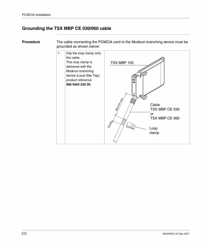
PCMCIA installation
Grounding the TSX MBP CE 030/060 cable
Procedure The cable connecting the PCMCIA card to the Modicon branching device must be grounded as shown below:
1 Clip the loop clamp onto the cable.This loop clamp is delivered with the Modicon branching device (Local Site Tap), product reference 990 NAD 230 00.
TSX MBP 100
CableTSX MBP CE 030orTSX MBP CE 060
Loopclamp
222 335009581 02 May 2007

PCMCIA installation
2 Fix the clamp + cable unit to the frame. The frame itself is connected to the ground.
335009581 02 May 2007 223
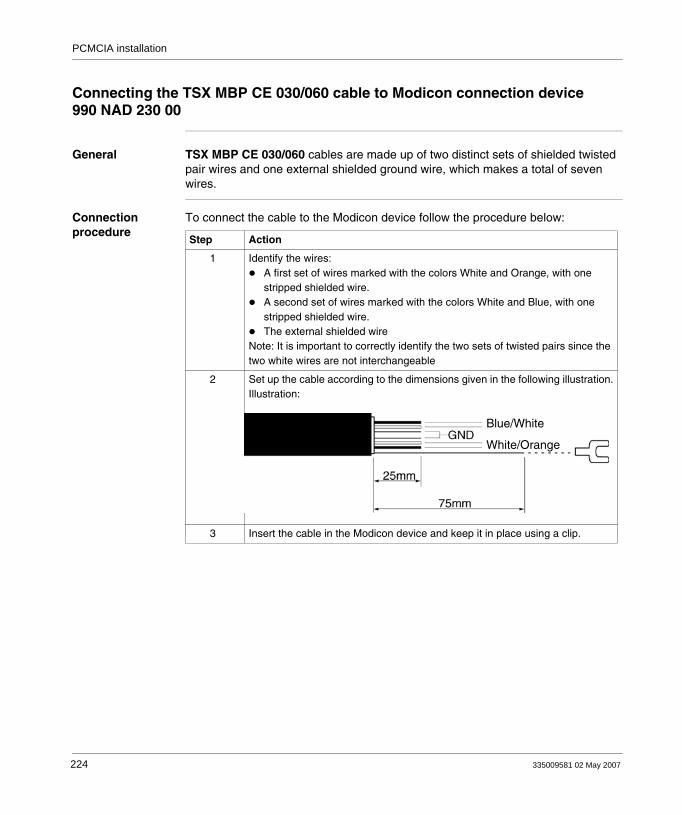
PCMCIA installation
Connecting the TSX MBP CE 030/060 cable to Modicon connection device 990 NAD 230 00
General TSX MBP CE 030/060 cables are made up of two distinct sets of shielded twisted pair wires and one external shielded ground wire, which makes a total of seven wires.
Connection procedure
To connect the cable to the Modicon device follow the procedure below:
Step Action
1 Identify the wires:A first set of wires marked with the colors White and Orange, with one stripped shielded wire.A second set of wires marked with the colors White and Blue, with one stripped shielded wire.The external shielded wire
Note: It is important to correctly identify the two sets of twisted pairs since the two white wires are not interchangeable
2 Set up the cable according to the dimensions given in the following illustration.Illustration:
3 Insert the cable in the Modicon device and keep it in place using a clip.
White/Orange
Blue/White
224 335009581 02 May 2007
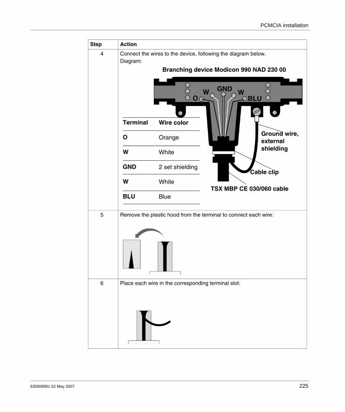
PCMCIA installation
4 Connect the wires to the device, following the diagram below.Diagram:
5 Remove the plastic hood from the terminal to connect each wire:
6 Place each wire in the corresponding terminal slot:
Step Action
Wire color
Orange
White
2 set shielding
White
Blue
Terminal
O
W
GND
W
BLUTSX MBP CE 030/060 cable
Cable clip
Ground wire,external shielding
Branching device Modicon 990 NAD 230 00
335009581 02 May 2007 225

PCMCIA installation
7 Replace the hoods, and using a screwdriver press them to engage the wires in their slots:
8 Finally, fix an open terminal to the external shielding wire either by soldering or crimping, and connect it to the ground screw of the device as shown in stage 4 of the drawing.
Step Action
226 335009581 02 May 2007
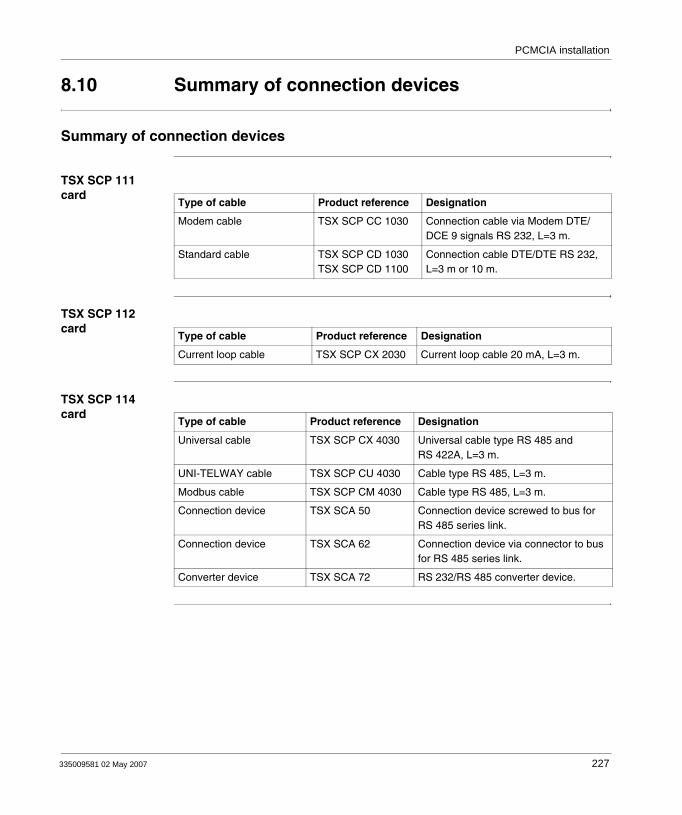
PCMCIA installation
8.10 Summary of connection devices
Summary of connection devices
TSX SCP 111 card
TSX SCP 112 card
TSX SCP 114 card
Type of cable Product reference Designation
Modem cable TSX SCP CC 1030 Connection cable via Modem DTE/DCE 9 signals RS 232, L=3 m.
Standard cable TSX SCP CD 1030 TSX SCP CD 1100
Connection cable DTE/DTE RS 232, L=3 m or 10 m.
Type of cable Product reference Designation
Current loop cable TSX SCP CX 2030 Current loop cable 20 mA, L=3 m.
Type of cable Product reference Designation
Universal cable TSX SCP CX 4030 Universal cable type RS 485 and RS 422A, L=3 m.
UNI-TELWAY cable TSX SCP CU 4030 Cable type RS 485, L=3 m.
Modbus cable TSX SCP CM 4030 Cable type RS 485, L=3 m.
Connection device TSX SCA 50 Connection device screwed to bus for RS 485 series link.
Connection device TSX SCA 62 Connection device via connector to bus for RS 485 series link.
Converter device TSX SCA 72 RS 232/RS 485 converter device.
335009581 02 May 2007 227

PCMCIA installation
TSX FPP 10 and TSX FPP 20 cards
TSX MBP 100 card
Type of cable Product reference Designation
FIPWAY/FIPIO cable TSX FP CG 010 Connection cable, L=1 m.
FIPWAY/FIPIO cable TSX FP CG 030 Connection cable, L=3 m.
Connection device TSX FP ACC4 FIPWAY/FIPIO connection device.
Connection device TSX FP ACC12 FIPWAY/FIPIO connection device.
Type of cable Product reference Designation
Modbus+ cable TSX MBP CE 030 Connection cable, L=3 m.
Modbus+ cable TSX MBP CE 060 Connection cable, L=6 m.
228 335009581 02 May 2007

PCMCIA installation
8.11 Precautions when connecting PCMCIA cards
Precautions for connecting PCMCIA cards
Important Cards must be connected or disconnected in the host device (processor or TSX SCY 21601) when the device is switched off.
The ferule, placed in direct contact with the PCMCIA card device, is used to handle electrical interference carried by the link cable braids.
335009581 02 May 2007 229

PCMCIA installation
8.12 Consumption of PCMCIA cards
Consumption of PCMCIA cards
TSX SCP 111 Table of consumption:
TSX SCP 112 Table of consumption:
TSX SCP 114 Table of consumption:
TSX FPP 10 and TSX FPP 20
Table of consumption:
TSX MBP 100 Table of consumption:
Voltage Typical current Maximum current Dissipated power
5 volts 140 mA 300 mA 1.5 W max.
Voltage Typical current Maximum current Dissipated power
5 volts 120 mA 300 mA 1.5 W max.
Voltage Typical current Maximum current Dissipated power
5 volts 150 mA 300 mA 1.5 W max.
Voltage Typical current Maximum current Dissipated power
5 volts 280 mA 330 mA 1.65 W max.
Voltage Typical current Maximum current Dissipated power
5 volts 220 mA 310 mA 1.55 W max.
230 335009581 02 May 2007
335009581 02 May 2007
9
TSX SCA 64 connection deviceAt a Glance
Aim of this Chapter
This Chapter introduces the functions of the TSX SCA 64 connection device.
What's in this Chapter?
This chapter contains the following sections:
Section Topic Page
9.1 General Introduction 232
9.2 Physical Description 234
9.3 Dimensions and Mounting 236
9.4 Installation 238
9.5 Wiring the TSX SCP CM 4530 239
9.6 Bus Cable Shield Cabling 240
9.7 Device Configuration and Transmission Pair Polarization 248
9.8 Adapting the Line End 256
231

TSX SCA 64
9.1 General Introduction
General Introduction
General Points The TSX SCA 64 unit is a cabling accessory, which allows a 2 or 4 wire mode communication module to be connected to a Modbus, Jbus or Jnet.
In 2-Wire Mode In this mode, connectable communication interfaces are:The built-in channel of the TSX SCY 11601/21601 modules, via a TSX CM 6530 cable,The TSX SCP/JNP 114 PCMCIA card, via a TSX SCP CM 6530 cable.
Illustration This diagram shows the general principal for connecting in 2-wire mode for a TSX SCY 21601.
Note: Connection can be made to either the JM or the JS connector, regardless of channel configuration (master or slave).
or
or
Bus
Bus Bus1 = JM connector2 = JS connector
••
232 335009581 02 May 2007

TSX SCA 64
In 4-Wire Mode In this mode, the connectable communication interface is:A PCMCIA TSX SCP/JNP 114 card, via a TSX SCP CM 4530 cable, through a TSX SCP CM 6530 cable.
Connect the TSX SCP CM 6530 cable to the:JM connector if the PCMCIA card channel is configured in master mode,JS connector if the PCMCIA card channel is configured in slave mode.
Illustration This diagram shows the general principal for connecting in 4-wire mode.
or
Bus
BusBus
(master channel)
(slave channel)
1 = JM connector2 = JS connector
335009581 02 May 2007 233
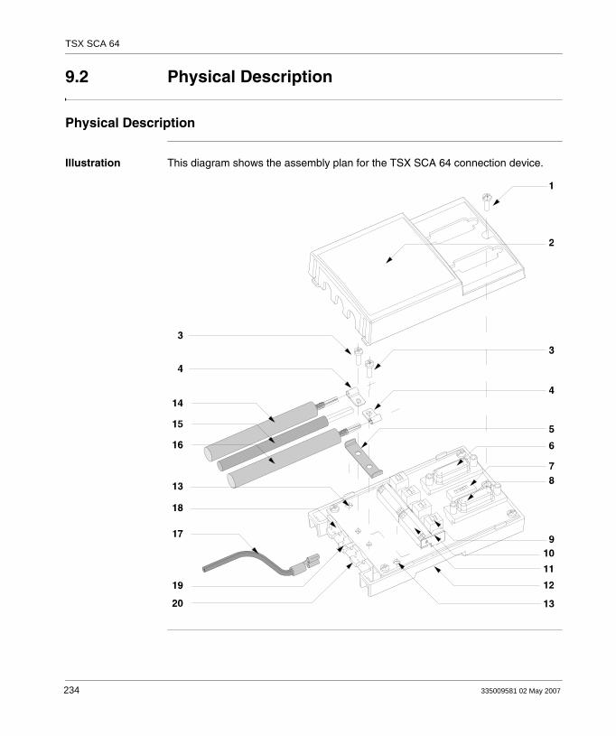
TSX SCA 64
9.2 Physical Description
Physical Description
Illustration This diagram shows the assembly plan for the TSX SCA 64 connection device.
234 335009581 02 May 2007

TSX SCA 64
Nodes The following table describes the different nodes, which make up the connection device.No. Description
1 Cover screws
2 Device cover
3 Screws fixing restart ground clamps
4 Restart ground clamps
5 Metallic part providing the ground link between the 2 cables
6 SUB D 15 pin female (JM) connector able to receive:In 2-wire mode: the male connector of a TSX SCY CM 6530 or TSX SCP CM 4530 connection cable, whether the channel is master or slave,In 4-wire mode: the male connector of a TSX SCP CM 4530 connection cable, if the channel is master,Or a TSX SCA 10 line terminator if the device is located at the beginning or end of the line,Or a male analyzer connection cable connector
7 1 micro-switch allowing configuration in 2-or 4-wire operation
8 SUB D 15 pin female (JS) connector able to receive:In 2-wire mode: the male connector of a TSX SCY CM 6530 or TSX SCP CM 4530 connection cable, whether the channel is master or slave,In 4-wire mode: the male connector of a TSX SCP CM 4530 connection cable, if the channel is slave,Or a TSX SCA 10 line terminator if the device is located at the beginning or end of the line,Or a male analyzer connection cable connector
9 4 micro-switches allowing polarization mode to be configured
10 Terminal to connect green/yellow ground wire
11 Connection terminals for the main connection cables providing bus continuity
12 Device Connection Base
13 Screw holes (4 diameter) to fix the device to a board or panel (60mm apart)
14 Main 2 or 3 pair cable providing bus continuity (max. 10 diameter), for connection to JA
15 5VDC power supply cable (for external polarization if required) for connection to JC
16 Main 2 or 3 pair cable providing bus continuity (max. 10 diameter), for connection to JB
17 Green/yellow device grounding cable
18 Main cable with corresponding ground format connected to local ground via a surge suppressor
19 Power supply cable and green/yellow ground wire
20 Main cable with corresponding ground format connected to local ground
Note: Nodes 14 and 16 are not included with the TSX SCA 64 device.
335009581 02 May 2007 235

TSX SCA 64
9.3 Dimensions and Mounting
Dimensions and Mounting
Dimensions This diagram shows the dimensions of the RSX SCA 64 connection device.
Mounting/Fixing The device can be mounted either:on a board or panel, secured with 2 M4 screws (min. length 20mm),on a DIN profile - Refs. AM1-DP 200 or AM1-DE 200 (Schneider catalog references).
236 335009581 02 May 2007

TSX SCA 64
Drilling Template This diagram shows the plan for mounting on a board or panel.
(1) Screw hole diameter must besuitable for M4 screw
335009581 02 May 2007 237

TSX SCA 64
9.4 Installation
Installation
Required Hardware
Installing the TSX SCA 64 device requires:a 2.5mm wide flat tipped screwdriver,a cross tipped screwdriver (PZ01).
Procedure The labels in the text below correspond with those found in the description of the device.
Step Action
1 Unscrew screw 1 with a PZ01 screwdriver, open cover 2.
2 Fix device connection base to its support:either a DIN AM1-DP200 or AM1-DE 200 profile,or a board or panel, and secure with 2 M4 screws (min. length 20mm).
3 Prepare main cables 14 and 16 according to the connection type selected, as indicated on the following pages.
4 Position the ground clamps 4 onto the cables.
5 Position the ground link 5, if necessary, according to the type of connection selected, as indicated on the following pages.
6 Connect the main cables (and the power supply cable if necessary) to terminal 11 according to the type of connection selected, as indicated on the following pages.The cable wires should have DZ5-CE005 cable ends (for the main cables) and DZ5-CE007 cable ends (for the power supply cable).Use a 2.5mm wide flat tipped screwdriver.
Torque on terminal screw 0.25 N.m.
7 Screw on the ground clamps and link with the screws 3, using a cross tipped PZ01 screwdriver.
8 Connect the green/yellow ground wire 17 to connection terminal 10.
9 Secure the cables with nylon clips. (Attach the green/yellow wire to the power supply cable if it is present).
10 Set the micro-switches 7 and 9 to the desired configuration; see configurations on following pages.
11 Break the scored tabs on the cover 2 to make way for the cables.
12 Mount the cover 2 and secure it with the screw 1 using a cross tipped PZ01 screwdriver.
≤
238 335009581 02 May 2007

TSX SCA 64
9.5 Wiring the TSX SCP CM 4530
Wiring the TSX SCP CM 4530
Illustration
J1 connector(PCMCIA side)
15-way SUBDconnector
12 Tx-
11 Tx+
20 Pull down
18 Pull up
1 Rx-
2 Rx+
16 0 volt
Green/White
White/Green
White/Blue
Blue/White
White/Orange
Orange/White
Brown/White
7
14
15
12
16
13
8
335009581 02 May 2007 239

TSX SCA 64
9.6 Bus Cable Shield Cabling
At a Glance
Aim of this Section
This section describes the different local grounding principles for the bus.
What's in this Section?
This section contains the following topics:
Topic Page
Local Grounding the Bus: General 241
Connecting the Shield to the Local Ground and to the Two Ends of the Cable (Recommended Cable Type)
243
Connecting the Shield to the Local Ground at One End of the Cable and to the Local Ground via a Surge Suppressor at the Other End
244
Connecting the Shielding to the Local Ground at One End and Isolating it From the Ground at the Other End.
246
240 335009581 02 May 2007

TSX SCA 64
Local Grounding the Bus: General
Introduction The bus can be grounded in three different ways:connecting the shield to the local ground and to the two ends of the cable,connecting the shield to the local ground at one end and to the local ground via a surge suppressor at the other end,connecting the shielding to the local ground at one end and isolating it from the ground at the other end.
Principle Opposite each main cable path, a copper pad grounds the cable shields:The path shown 20 locally grounds the cable shielding.The path shown 18 locally grounds the cable shielding via a surge suppressor.
Illustration This diagram shows the principle for locally grounding the device as a whole.
Localground
335009581 02 May 2007 241

TSX SCA 64
Cable Preparation Template: Introduction
Certain precautions must be taken in order to ensure correct placement of the bus cables:
following the stripping template,using the following cable ends:
DZ5-CE005 for the main cables,DZ5-CE007 for the power supply cable.
This diagram shows the local grounding principle for the device as a whole.
Shielding
242 335009581 02 May 2007
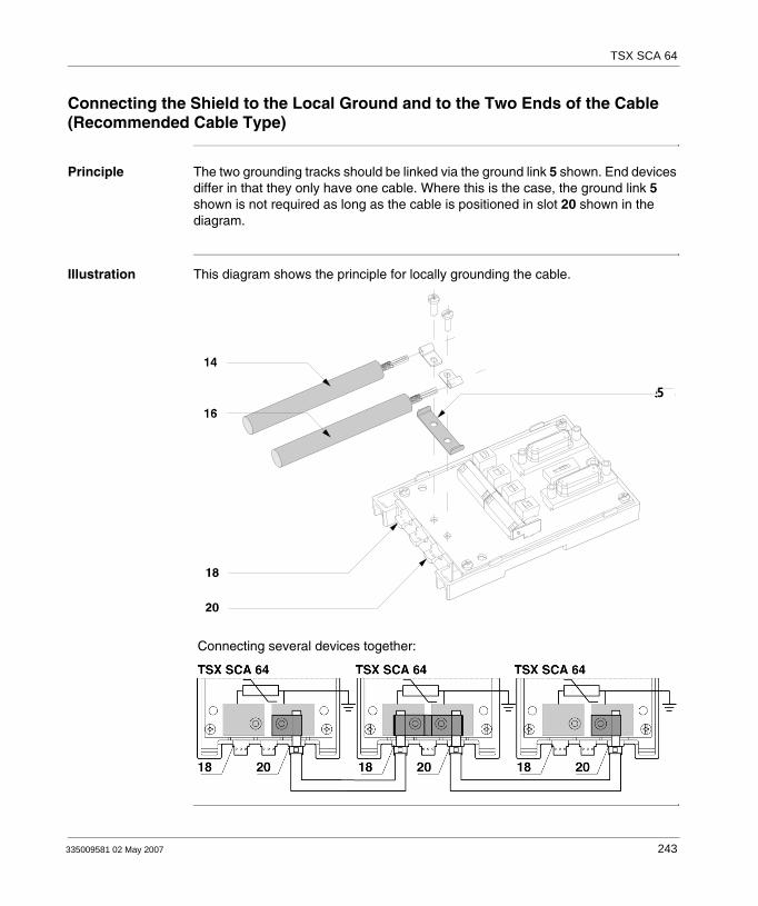
TSX SCA 64
Connecting the Shield to the Local Ground and to the Two Ends of the Cable (Recommended Cable Type)
Principle The two grounding tracks should be linked via the ground link 5 shown. End devices differ in that they only have one cable. Where this is the case, the ground link 5 shown is not required as long as the cable is positioned in slot 20 shown in the diagram.
Illustration This diagram shows the principle for locally grounding the cable.
5
Connecting several devices together:
5
335009581 02 May 2007 243

TSX SCA 64
Connecting the Shield to the Local Ground at One End of the Cable and to the Local Ground via a Surge Suppressor at the Other End
Principle Only cable 16 shown is connected to the local ground, cable 14 shown is connected to the local ground via a surge suppressor.
Note: Ground link 5 shown is not used
244 335009581 02 May 2007

TSX SCA 64
Illustration This diagram shows the principle for locally grounding the cable.
Connecting several devices together:
55
335009581 02 May 2007 245

TSX SCA 64
Connecting the Shielding to the Local Ground at One End and Isolating it From the Ground at the Other End.
Principle Only cable 16 shown is connected to the local ground, cable shielding 14 shown is isolated from the ground by a thermo-retractable tube (not included).
Note: In this case, ground link 5 shown is not used.
246 335009581 02 May 2007
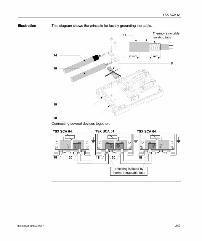
TSX SCA 64
Illustration This diagram shows the principle for locally grounding the cable.
Connecting several devices together:
Thermo-retractableisolating tube
Shielding isolated by thermo-retractable tube
335009581 02 May 2007 247
TSX SCA 64
9.7 Device Configuration and Transmission Pair Polarization
At a Glance
Aim of this Section
This section contains the different configurations of the TSX SCA 64 device.
What's in this Section?
This section contains the following topics:
Topic Page
4-wire Configuration with 2-pair Polarization via 5VDC External Power Supply 249
4-wire Configuration with Polarization of One Pair by the Master Station and the Other by a Slave Station
251
2-wire Configuration with Data Pair Polarization by a Station 254
248 335009581 02 May 2007
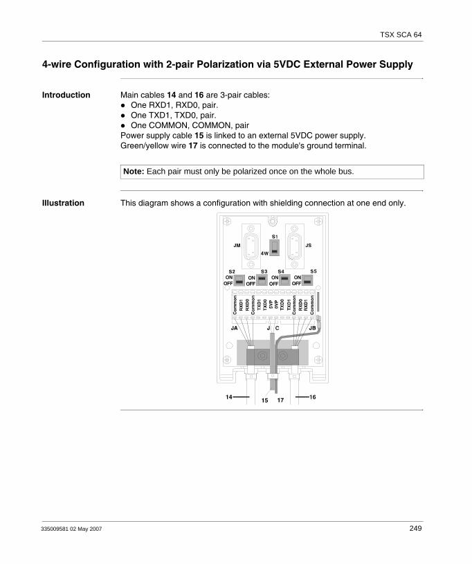
TSX SCA 64
4-wire Configuration with 2-pair Polarization via 5VDC External Power Supply
Introduction Main cables 14 and 16 are 3-pair cables:One RXD1, RXD0, pair.One TXD1, TXD0, pair.One COMMON, COMMON, pair
Power supply cable 15 is linked to an external 5VDC power supply.Green/yellow wire 17 is connected to the module's ground terminal.
Illustration This diagram shows a configuration with shielding connection at one end only.
Note: Each pair must only be polarized once on the whole bus.
335009581 02 May 2007 249

TSX SCA 64
Position of the Switches
This table shows the switch positions.
Switches Position on
Device receiving power supply
Other devices
S1 4W 4W
S2 OFF OFF
S3 ON OFF
S4 ON OFF
S5 OFF OFF
250 335009581 02 May 2007

TSX SCA 64
4-wire Configuration with Polarization of One Pair by the Master Station and the Other by a Slave Station
Introduction Main cables 14 and 16 are 3-pair cables:One RXD1, RXD0, pair.One TXD1, TXD0, pair.One COMMON, COMMON, pair
Green/yellow wire 17 is connected to the module's ground terminal.
Illustration This diagram shows a configuration with RXD1, RXD0 pair polarization by the master station connected to JM.
Note: Each pair must only be polarized once on the whole bus,These diagrams show a configuration with shielding connection at one end only.
335009581 02 May 2007 251

TSX SCA 64
Position of the Switches
This table shows the switch positions.
Illustration This diagram shows a configuration with TXD1 and TXD0 pair polarization by one of the slave stations connected to JS.
Switches Positions on
master station device
S1 4W
S2 ON
S3 OFF
S4 OFF
S5 OFF
252 335009581 02 May 2007

TSX SCA 64
Position of the Switches
This table shows the switch positions.
Switches Positions on
one of the slave stations other slave stations
S1 4W 4W
S2 OFF OFF
S3 OFF OFF
S4 OFF OFF
S5 ON OFF
335009581 02 May 2007 253

TSX SCA 64
2-wire Configuration with Data Pair Polarization by a Station
Introduction Main cables 14 and 16 are 2-pair cables:One RXD1, RXD0, pair.One COMMON, COMMON, pair
Green/yellow wire 17 is connected to the module's ground terminal.
Illustration This diagram shows a configuration with shielding connection at one end only.
Note: This pair is only polarized once on the whole bus.
254 335009581 02 May 2007

TSX SCA 64
Position of the Switches
This table shows the switch positions.
Switches Position on
master station device slave stations
S1 2W 2W
S2 ON OFF
S3 OFF OFF
S4 OFF OFF
S5 OFF OFF
335009581 02 May 2007 255

TSX SCA 64
9.8 Adapting the Line End
Line End Adaptation
At a Glance Each end of the bus cable must have a line end jack adaptor. This line end jack adapter can be plugged into free connectors on either JM (master) or JS (slave) on TSX SCA 64 devices, located at the ends of the bus.A TSX SCA 10 kit consisting of 2 SUB D 15 pin connectors plus accessories (cover, screws, wiring etc.) enables the user to configure and set up the line end jacks.
Illustration This view shows a line end jack.
SCA 64 Mounting Example
This example shows a communication bus with 4 TSXx SCA 64 connection devices.
To TSX SCY 21601 modules
Line end jack Line end jack
Bus BusBus
256 335009581 02 May 2007

TSX SCA 64
Installing Line End Jacks: At a Glance
The configuration is attained by plugging each SUB D 15 pin 2-wire connector (supplied) into the sockets, enabling line adaptation.This diagram shows the configuration:
Mounting Procedure
Installation
RXD1, RXD0 pair
TXD1, TXD0 pair
Cabling viewResistance andseries capacitytype adaptation
Status Action
1 Plug the wires supplied into the SUB D 15 pin connectors as shown above.
2 Put the connector into place in one of the half-covers (the connector can be either way up).
3 Attach the latch screw.
4 Put the sleeve into place.
5 Cover it all with the other half-cover, taking care not to damage the wires.
6 Screw in or clip on the two half-covers (depending upon the type included).
7 Use the blank labels provided to show utilization.Note:Cable clamps and/or other accessories should not be used.
335009581 02 May 2007 257

TSX SCA 64
Connecting an Analyzer
The JM or JS connectors on the TSX SCA 64 device can support a frame analyzer, which is connected by a SUB D 15 (male) pin connector. Signals relating to each pair are available on the device connectors as indicated in the diagram below.This diagram shows the connections for different pairs of the analyzer cable.
Tx
Rx
TSX SCA 64 device15 pin (female) SUB Dconnector
258 335009581 02 May 2007

335009581 02 May 2007
VI
Communication: Modules TSX ETY 110/410•/PORT/510• and TSX WMY 100At a Glance
Aim of this Part This part deals with the hardware installation of the ETHERNET network TSX ETY 110, TSX ETY 410•/PORT/510• and TSX WMY 100 modules on a Premium/Atrium PLC.
What's in this Part?
This part contains the following chapters:
Chapter Chapter Name Page
10 Communication: TSX ETY 110 module 261
11 Communication: Modules TSX ETY 410•/PORT/510• and TSX WMY 100
277
259

TSX ETY 110/410•/PORT/510• and TSX WMY 100
260 335009581 02 May 2007
335009581 02 May 2007
10
Communication: TSX ETY 110 moduleAt a Glance
Aim of this Chapter
This Chapter deals with installing the Ethernet network module TSX ETY 110, in a Premium/Atrium PLC.
What's in this Chapter?
This chapter contains the following sections:
Section Topic Page
10.1 At a Glance 262
10.2 Description 263
10.3 Characteristics of the Ethernet channel 264
10.4 Installing the TSX ETY 110 module 265
10.5 Connection via the AUI interface 270
10.6 10baseT Interface 273
10.7 Display panel, diagnostics 275
10.8 Electrical features 276
261

TSX ETY 110
10.1 At a Glance
At a Glance
General Communication module TSX ETY 110 is used to communicate in an Ethernet architecture. It is made up of a communication channel which offers two types of connections:
Connection to an ETHWAY network supporting common words and X-Way UNI-TE message-handling services on an ETHWAY profile.Connection to a TCP-IP network supporting the X-Way UNI-TE message-handling service.
This module also ensures transparent routing of X-Way UNI-TE messages from a TCP-IP network to an X-Way network, and vice versa.
Please refer to the Ethernet reference manual for wiring an ETHWAY architecture.
262 335009581 02 May 2007
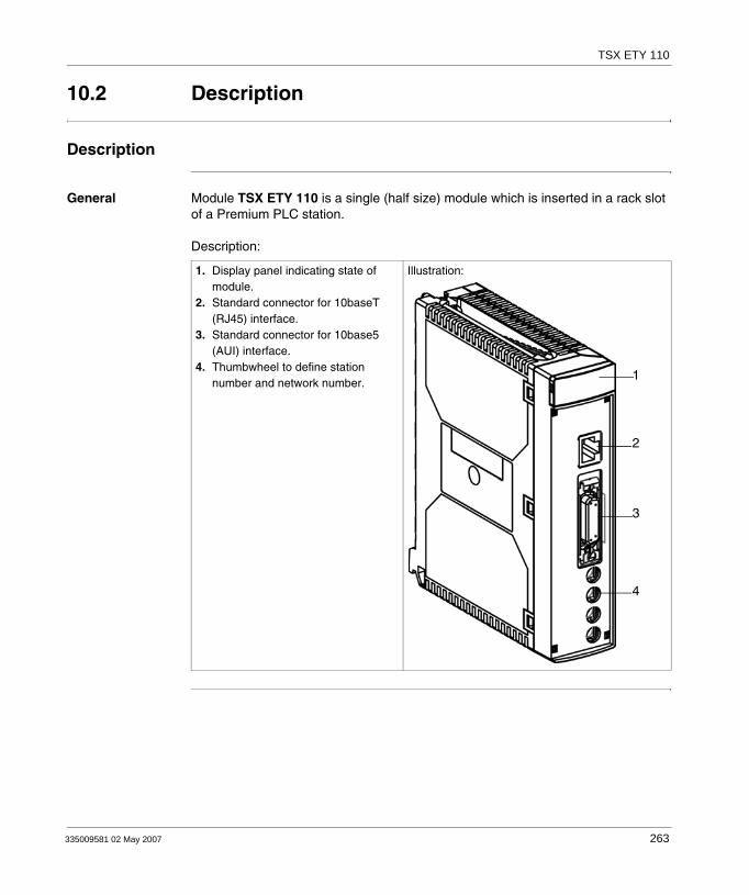
TSX ETY 110
10.2 Description
Description
General Module TSX ETY 110 is a single (half size) module which is inserted in a rack slot of a Premium PLC station. Description:
1. Display panel indicating state of module.
2. Standard connector for 10baseT (RJ45) interface.
3. Standard connector for 10base5 (AUI) interface.
4. Thumbwheel to define station number and network number.
Illustration:
1
2
3
4
335009581 02 May 2007 263
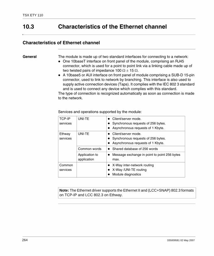
TSX ETY 110
10.3 Characteristics of the Ethernet channel
Characteristics of Ethernet channel
General The module is made up of two standard interfaces for connecting to a network: One 10baseT interface on front panel of the module, comprising an RJ45 connector, which is used for a point to point link via a linking cable made up of two twisted pairs of impedance 100 Ω ± 15 Ω.A 10base5 or AUI interface on front panel of module comprising a SUB-D 15-pin connector, used to link to network by branching. This interface is also used to supply active connection devices (Taps). It complies with the IEC 802 3 standard and is used to connect any device which complies with this standard.
The type of connection is recognized automatically as soon as connection is made to the network.
Services and operations supported by the module:
TCP-IP services
UNI-TE Client/server mode.Synchronous requests of 256 bytes.Asynchronous requests of 1 Kbyte.
Ethway services
UNI-TE Client/server mode.Synchronous requests of 256 bytes.Asynchronous requests of 1 Kbyte.
Common words Shared database of 256 words
Application to application
Message exchange in point to point 256 bytes max.
Common services
X-Way inter-network routingX-Way /UNI-TE routingModule diagnostics
Note: The Ethernet driver supports the Ethernet II and (LCC+SNAP) 802.3 formats on TCP-IP and LCC 802.3 on Ethway.
264 335009581 02 May 2007
TSX ETY 110
10.4 Installing the TSX ETY 110 module
At a Glance
Aim of this Section
This Section deals with installing module TSX ETY 110 in a PLC.
What's in this Section?
This section contains the following topics:
Topic Page
At a Glance 266
Selecting the Type of Processor 267
Wiring/Unwiring with power switched on 268
Station address coding 269
335009581 02 May 2007 265

TSX ETY 110
At a Glance
General The communication module TSX ETY 110 is mounted in the rack slot of a Premium/Atrium PLC station. It can be installed in any available slot (except in the offset X Bus racks), on condition that the supply constraints of the rack are observed (see Electrical characteristics, p. 276).
266 335009581 02 May 2007

TSX ETY 110
Selecting the Type of Processor
Selection Guide Selecting the processor to control the PLC station will depend on the number of network connections required.
Processors Number of network connections
Number of ETY 110 modules per station (*)
TSX 57 P 1../2..PCX 57 253
1 1
TSX P 57 3...PCX 57 353
3 3
TSX P 57 4.. 4 4
(*) on condition of a consumption report on the 5V, compatible with the supply selected.
335009581 02 May 2007 267
TSX ETY 110
Wiring/Unwiring with power switched on
The module Module TSX ETY 110 can be wired or unwired with power switched on without disrupting the operation of the station.The module does not have a RAM internal backup memory function: this will be erased when power is switched off.The module initializes itself when power is switched on. A communication break can be expected during this intervention.
The link The SUB-D 15-pin connectors of the AUI interface and the RJ45 connector of the 10baseT interface can be connected or disconnected when power is on. A communication break can therefore be expected in the application in progress.
268 335009581 02 May 2007
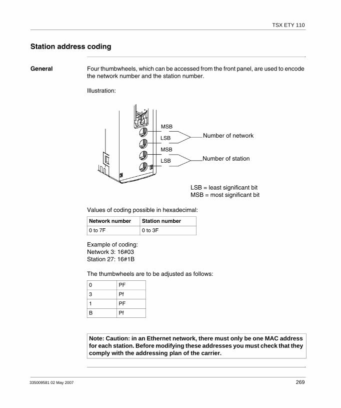
TSX ETY 110
Station address coding
General Four thumbwheels, which can be accessed from the front panel, are used to encode the network number and the station number.
Illustration:
Values of coding possible in hexadecimal:
Example of coding:Network 3: 16#03Station 27: 16#1B
The thumbwheels are to be adjusted as follows:
Network number Station number
0 to 7F 0 to 3F
0 PF
3 Pf
1 PF
B Pf
Note: Caution: in an Ethernet network, there must only be one MAC address for each station. Before modifying these addresses you must check that they comply with the addressing plan of the carrier.
Number of network
Number of station
MSB
MSB
LSB
LSB
LSB = least significant bitMSB = most significant bit
335009581 02 May 2007 269

TSX ETY 110
10.5 Connection via the AUI interface
Connection by AUI interface
General This interface is used to connect all types of devices which comply with the physical layer defined in the OSI 802.3 standard (10base5, 10base2, FOIRL, etc.) through a transceiver.
Module TSX ETY 110 can provide a remote power supply for the transceiver through the Sub-D connector with the following characteristics:
Imax = 0.5 mA12 V-6%<Usupply<15 V+15%
The module is connected to the main cable via a transceiver and by the following branch cables:
TSX ETY CB 005 - Length 5 mTSX ETY CB 010 - Length 10 mTSX ETY CB 020 - Length 20 m
The maximum length of a branch may be 50 m. This length can be achieved by connecting several branch cables end to end.
Note: It is essential to use transceivers (TSX ETH ACC2) to connect two modules in point to point.
270 335009581 02 May 2007

TSX ETY 110
Connector pinouts
Sub-D 15 pins according to the OSI 802.3 standard:
Pin number Designation according to ISO 802.3
Use
1 CI-S (Control In Shield) GND
2 CI-A (Control In A) COLL+
3 DO-A (Data Out A) TD+
4 DI-S (Data In Shield) GND
5 DI-A (Data in A) RD+
6 VC (Voltage Common) GND
7 not used
8 not used
9 CI-B (Control In B) COLL-
10 DO-B (Data Out B) TD-
11 DO-S (Data Out Shield) GND
12 DI-B (Date In B) RD-
13 VP (Voltage Plus) 12 V
14 VS (Voltage Shield) GND
15 not used
Sub-D connector body
PG (Protective Ground) Protective ground
335009581 02 May 2007 271

TSX ETY 110
Topology Illustration:
Locking The Sub-D connector is equipped with a sliding lock system The connector is locked by sliding the tab to the bottom. To ensure the module works properly in a disturbed environment it is essential to carry out the locking procedure. Illustration:
TSX ETY CBXXX
Sender/ReceiverTSX ACC2
Station jStation i
Locking tab
272 335009581 02 May 2007

TSX ETY 110
10.6 10baseT Interface
10baseT interface
General This interface has a standard type RJ45 connector. These connection cables are widely used in business.
In an industrial environment, you must use a cable with the following characteristics: Shielded twisted double pairImpedance 100 Ω±15 Ω (from 1 to 16 MHz)Maximum attenuation 11.5 dB/100 metersMaximum length 100 meters
The 10baseT connection is a point to point connection to form a star-shaped network. The stations are connected to concentrators or switches.
Pinouts Illustration:
Reminder of pinouts:
Pin Signal
1 TD+
2 TD-
3 RD+
4 not connected
5 not connected
6 RD-
7 not connected
8 not connected
335009581 02 May 2007 273

TSX ETY 110
Topology This link is used to create a star-shaped network with connections in point to point. The stations are connected to a concentrator (Hub). The concentrators can also be connected in cascade to increase network size.Illustration:
Station 1
Concentrator 1
Concentrator 2Station 2
Stations
Stations
274 335009581 02 May 2007
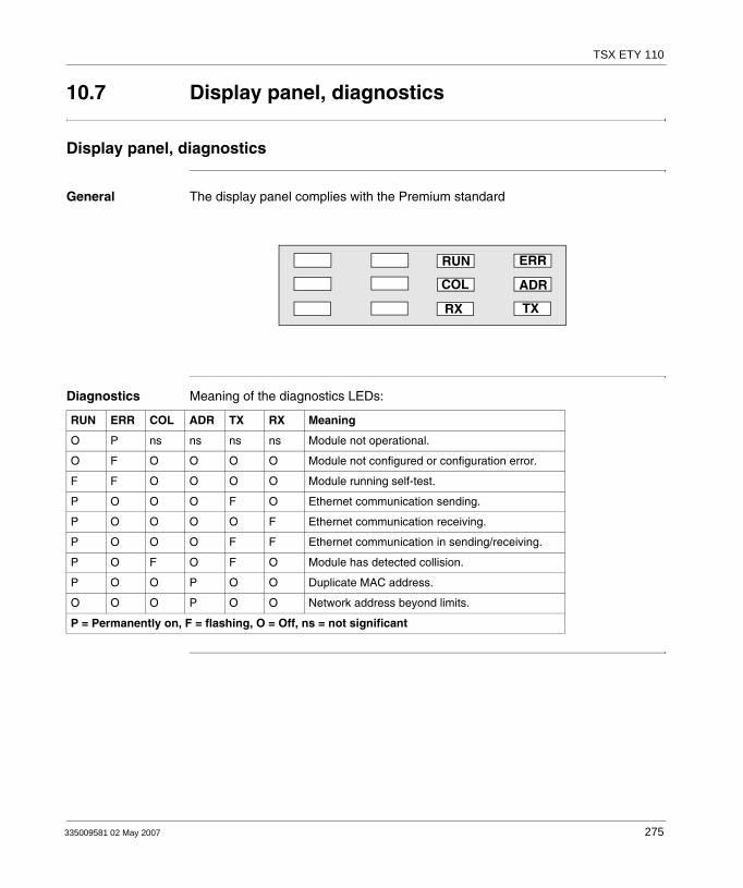
TSX ETY 110
10.7 Display panel, diagnostics
Display panel, diagnostics
General The display panel complies with the Premium standard
Diagnostics Meaning of the diagnostics LEDs:
RUN
COL
RX
ADR
ERR
TX
RUN ERR COL ADR TX RX Meaning
O P ns ns ns ns Module not operational.
O F O O O O Module not configured or configuration error.
F F O O O O Module running self-test.
P O O O F O Ethernet communication sending.
P O O O O F Ethernet communication receiving.
P O O O F F Ethernet communication in sending/receiving.
P O F O F O Module has detected collision.
P O O P O O Duplicate MAC address.
O O O P O O Network address beyond limits.
P = Permanently on, F = flashing, O = Off, ns = not significant
335009581 02 May 2007 275

TSX ETY 110
10.8 Electrical features
Electrical characteristics
General Module TSX ETY 110 can be inserted in any rack slot of a Premium/Atrium station (except in an X Bus offset rack). The module consumption from the supply depends on the selection made from the transceiver remote power supply option. Table of consumption:
Voltage Current consumed Dissipated power
5 volts Typical Maximum Typical Maximum
with remote power supply (RJ45)
0.8 A 1.2 A 4 W 6 W
with remote power supply (AUI)
1.2 A 2.5 A 6 W 12.5 W
Note: Caution: Modules TSX ETY 110 on 5 volts have high consumption when the AUI connection is used. Special attention should therefore be given what sort of devices are in the rack before deciding which kind of supply to choose.
Number of TSX ETY 110 modules which can be connected to a rack:2 modules with AUI connection.4 modules with RJ45 connection.
276 335009581 02 May 2007

335009581 02 May 2007
11
Communication: Modules TSX ETY 410•/PORT/510• and TSX WMY 100At a Glance
Aim of this Chapter
This Chapter deals with the hardware installation of ETHERNET network modules TSX ETY 410•/PORT, TSX ETY 510• and TSX WMY 100 in a Premium/Atrium PLC.
What's in this Chapter?
This chapter contains the following sections:
Section Topic Page
11.1 At a Glance 278
11.2 Description 279
11.3 Ethernet Channel Characteristics 280
11.4 Installation of TSX ETY 410•/PORT/510• and TSX WMY 100 281
11.5 10/100baseT interface 285
11.6 Display, Diagnostics 287
11.7 Electrical Characteristics 289
11.8 Standards 290
11.9 Operating Conditions 291
277

TSX ETY 410•/PORT TSX ETY 510• and TSX WMY 100
11.1 At a Glance
At a Glance
General Communication modules TSX ETY 410/PORT/510 and TSX WMY 100 are used to communicate in an Ethernet architecture. They are made up of a communication channel whose main features are as follows:
Connection to a TCP/IP network.Communication in Half and Full Duplex mode by automatic recognition.Transmission speed from 10 or 100 Mbits/s by automatic recognition.Connection to network by copper cable via an RJ45 connector.
These modules are used to carry out the following functions:X-WAY UNI-TE and Modbus messaging service on TCP/IP.I/O Scanning Service (except TSX WMY 100).SNMP Service.Address Server (except TSX WMY 100).Web server.Global Data (except TSX WMY 100).Time synchronization service (NTP).
278 335009581 02 May 2007

TSX ETY 410•/PORT TSX ETY 510• and TSX WMY 100
11.2 Description
Description
General TSX ETY 410•/PORT, TSX ETY 510• modules are standard format modules which are inserted in a slot on the main or extension rack of a Premium PLC station. Description:
1. Display panel indicating module status:
One green RUN LED.Two red LEDs: ERR and COL.Three yellow LEDs: STS, TX and RX.
2. Standard connector for 10baseT (RJ45) interface.
Illustration:
1
2
335009581 02 May 2007 279
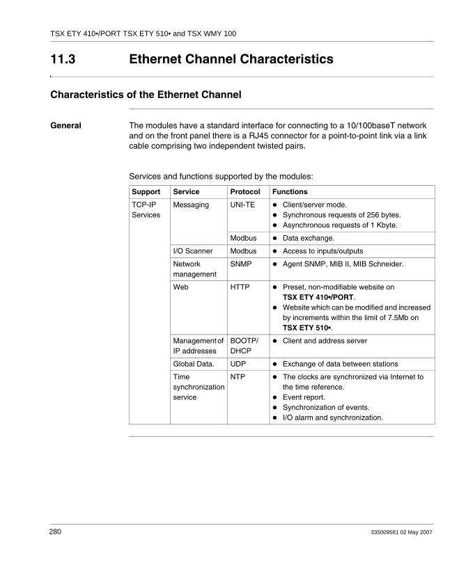
TSX ETY 410•/PORT TSX ETY 510• and TSX WMY 100
11.3 Ethernet Channel Characteristics
Characteristics of the Ethernet Channel
General The modules have a standard interface for connecting to a 10/100baseT network and on the front panel there is a RJ45 connector for a point-to-point link via a link cable comprising two independent twisted pairs.
Services and functions supported by the modules:
Support Service Protocol Functions
TCP-IP Services
Messaging UNI-TE Client/server mode.Synchronous requests of 256 bytes.Asynchronous requests of 1 Kbyte.
Modbus Data exchange.
I/O Scanner Modbus Access to inputs/outputs
Network management
SNMP Agent SNMP, MIB II, MIB Schneider.
Web HTTP Preset, non-modifiable website on TSX ETY 410•/PORT.Website which can be modified and increased by increments within the limit of 7.5Mb on TSX ETY 510•.
Management of IP addresses
BOOTP/DHCP
Client and address server
Global Data. UDP Exchange of data between stations
Time synchronization service
NTP The clocks are synchronized via Internet to the time reference.Event report.Synchronization of events.I/O alarm and synchronization.
280 335009581 02 May 2007
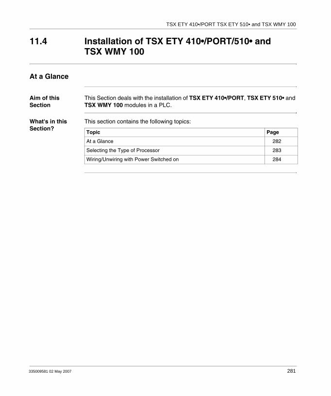
TSX ETY 410•/PORT TSX ETY 510• and TSX WMY 100
11.4 Installation of TSX ETY 410•/PORT/510• and TSX WMY 100
At a Glance
Aim of this Section
This Section deals with the installation of TSX ETY 410•/PORT, TSX ETY 510• and TSX WMY 100 modules in a PLC.
What's in this Section?
This section contains the following topics:
Topic Page
At a Glance 282
Selecting the Type of Processor 283
Wiring/Unwiring with Power Switched on 284
335009581 02 May 2007 281

TSX ETY 410•/PORT TSX ETY 510• and TSX WMY 100
At a Glance
General TSX ETY 410•/PORT and TSX ETY 510• communication modules are mounted in the rack slot of a Premium/Atrium PLC station. They can be installed in any available slot (except in an offset X Bus rack), on condition that the supply constraints of the rack are observed (see Electrical Characteristics, p. 289).
282 335009581 02 May 2007

TSX ETY 410•/PORT TSX ETY 510• and TSX WMY 100
Selecting the Type of Processor
Selection Guide Selecting the processor to control the PLC station will depend on the number of network connections required.
Compatibility Depending on the software version of the processor, all or some of the functions of the TSK-ETY 4102/PORT/5102 modules will be available. The table below gives the compatibility rules.
Processors Number of network connections
Number of ETY 4102/PORT/5102 per station (*)
TSX 57 P 1../2..PCX 57 253
1 1
TSX P 57 3...PCX 57 353
3 3
TSX P 57 4.. 4 4
(*) on condition of a consumption report on the 5V, compatible with the supply selected.
Software version of the processor
Supported functions Type to be configured in PL7
VL < 3.3 Does not accept the modules TSX ETY4•••/5•••
-
3.3 £ VL < 5.1 Functions limited to those of the TSX ETY 410/5101 modules
TSX ETY 410 or 5101
VL 5.1 Supports all the functions of the TSX ETY 4102/PORT/5102 modules
TSX ETY 4102/PORT or 5102
335009581 02 May 2007 283

TSX ETY 410•/PORT TSX ETY 510• and TSX WMY 100
Wiring/Unwiring with Power Switched on
The Module The TSX ETY 410•/PORT and TSX ETY 510• modules can be wired or unwired when switched on without disrupting the operation of the station.The modules do not have an internal RAM backup memory function: this will be erased when power is switched off.The modules reset when switched on. A communication break can be expected during these interventions.
The link The 10/100baseT interface RJ45 connector can be connected or disconnected when power is on. A communication break can therefore be expected in the application in progress.
284 335009581 02 May 2007

TSX ETY 410•/PORT TSX ETY 510• and TSX WMY 100
11.5 10/100baseT interface
10/100base T Interface
General This interface has a standard type RJ45 connector.
Refer to the ETHERNET reference manual for the connection accessories that comply with environmental circumstances the PLC requires in an industrial setting.
Pin Assignment Illustration:
Reminder of pin assignment:
Pin Signal
1 TD+
2 TD-
3 RD+
4 not connected
5 not connected
6 RD-
7 not connected
8 not connected
335009581 02 May 2007 285
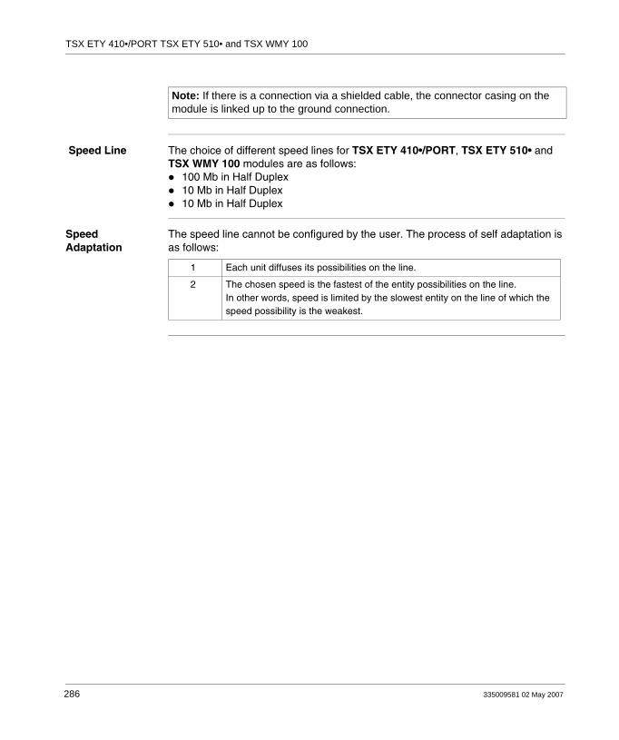
TSX ETY 410•/PORT TSX ETY 510• and TSX WMY 100
Speed Line The choice of different speed lines for TSX ETY 410•/PORT, TSX ETY 510• and TSX WMY 100 modules are as follows:
100 Mb in Half Duplex10 Mb in Half Duplex10 Mb in Half Duplex
Speed Adaptation
The speed line cannot be configured by the user. The process of self adaptation is as follows:
Note: If there is a connection via a shielded cable, the connector casing on the module is linked up to the ground connection.
1 Each unit diffuses its possibilities on the line.
2 The chosen speed is the fastest of the entity possibilities on the line.In other words, speed is limited by the slowest entity on the line of which the speed possibility is the weakest.
286 335009581 02 May 2007

TSX ETY 410•/PORT TSX ETY 510• and TSX WMY 100
11.6 Display, Diagnostics
Display panel, Diagnostics
General The display panel conforms to the Premium standard
The COL, RX and TX LEDs are managed by the line’s electronics; they indicate:COL: a collision.RX: a receptionTX: a transmission.
RUN
STS
RX
ADR
ERR
TX
335009581 02 May 2007 287
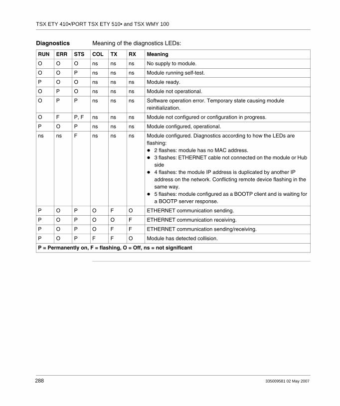
TSX ETY 410•/PORT TSX ETY 510• and TSX WMY 100
Diagnostics Meaning of the diagnostics LEDs:
RUN ERR STS COL TX RX Meaning
O O O ns ns ns No supply to module.
O O P ns ns ns Module running self-test.
P O O ns ns ns Module ready.
O P O ns ns ns Module not operational.
O P P ns ns ns Software operation error. Temporary state causing module reinitialization.
O F P, F ns ns ns Module not configured or configuration in progress.
P O P ns ns ns Module configured, operational.
ns ns F ns ns ns Module configured. Diagnostics according to how the LEDs are flashing:
2 flashes: module has no MAC address.3 flashes: ETHERNET cable not connected on the module or Hub side4 flashes: the module IP address is duplicated by another IP address on the network. Conflicting remote device flashing in the same way.5 flashes: module configured as a BOOTP client and is waiting for a BOOTP server response.
P O P O F O ETHERNET communication sending.
P O P O O F ETHERNET communication receiving.
P O P O F F ETHERNET communication sending/receiving.
P O P F F O Module has detected collision.
P = Permanently on, F = flashing, O = Off, ns = not significant
288 335009581 02 May 2007
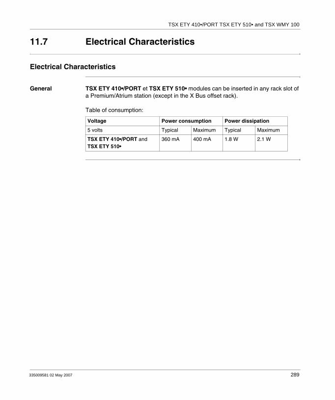
TSX ETY 410•/PORT TSX ETY 510• and TSX WMY 100
11.7 Electrical Characteristics
Electrical Characteristics
General TSX ETY 410•/PORT et TSX ETY 510• modules can be inserted in any rack slot of a Premium/Atrium station (except in the X Bus offset rack). Table of consumption:
Voltage Power consumption Power dissipation
5 volts Typical Maximum Typical Maximum
TSX ETY 410•/PORT and TSX ETY 510•
360 mA 400 mA 1.8 W 2.1 W
335009581 02 May 2007 289

TSX ETY 410•/PORT TSX ETY 510• and TSX WMY 100
11.8 Standards
Norms and Standards
Compliance with Standards
The TSX ETY 410•/PORT, TSX ETY 510• and TSX WMY 100 modules comply with the following standards:
UL 508CSAIEC 1121-2Marine classification
290 335009581 02 May 2007

TSX ETY 410•/PORT TSX ETY 510• and TSX WMY 100
11.9 Operating Conditions
Operating Conditions
Applicable Conditions
Configuration software:PL7 version < 4.1: recognizes TSX ETY 4102/5102 modules as TSX ETY 410/510PL7 version ≥ 4.1: recognizes TSX ETY 4102/5102 modules,PL7 version ≥ 4.3: recognizes processors including the TSX ETY PORT module.
Conditions of use:Temperature from 0 to +60° CRelative humidity of 10% to 95% (without condensation) to 60° CAltitude of between 0 and 4500 metersImmunity to vibrations complies with the IEC 68-2-6 standard, Fc testImmunity to shocks complies with the IEC 68-2-27 standard, Ea testImmunity to free fall, hardware dealt with as per the IEC 68-2-32 standard, method 1IP 20 protection index
Storage conditions:Temperature from -40° C to +85° CRelative humidity between 0% and 95% (without condensation) at 60° C
335009581 02 May 2007 291

TSX ETY 410•/PORT TSX ETY 510• and TSX WMY 100
292 335009581 02 May 2007

335009581 02 May 2007
VII
Communication: PCMCIA Modem cardAt a Glance
Aim of this Part This part deals with the TSX MDM 10 PCMCIA modem card.
What's in this Part?
This part contains the following chapters:
Chapter Chapter Name Page
12 Installing the TSX MDM 10 module 295
293

PCMCIA Modem
294 335009581 02 May 2007
335009581 02 May 2007
12
Installing the TSX MDM 10 moduleAt a Glance
Aim of this Chapter
This Chapter describes the hardware installation of the PCMCIA Modem card TSX MDM 10.
What's in this Chapter?
This chapter contains the following sections:
Section Topic Page
12.1 At a Glance 296
12.2 Description 297
12.3 Installation 298
12.4 Connecting adapters 303
12.5 Electrical characteristics 304
12.6 Technical specifications 305
295

TSX MDM 10
12.1 At a Glance
At a Glance
General The TSX MDM 10 card is used to connect to the switched telephone network (STN) for accessing remote stations following UNI-TELWAY or character mode protocols.
This type of communication is available using the Modem PCMCIA card. It is installed only in the PCMCIA reception slot on a Premium processor version V≥3.3.
296 335009581 02 May 2007
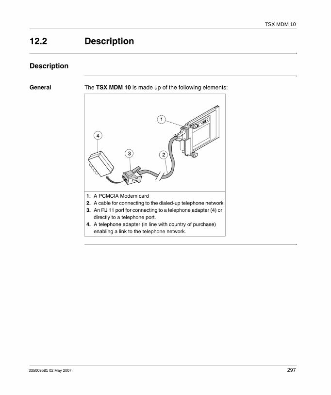
TSX MDM 10
12.2 Description
Description
General The TSX MDM 10 is made up of the following elements:
1. A PCMCIA Modem card2. A cable for connecting to the dialed-up telephone network3. An RJ 11 port for connecting to a telephone adapter (4) or
directly to a telephone port.4. A telephone adapter (in line with country of purchase)
enabling a link to the telephone network.
335009581 02 May 2007 297

TSX MDM 10
12.3 Installation
At a Glance
Aim of this Section
This Section deals with installing a PCMCIA Modem card in a Premium PLC TSX MDM 10.
What's in this Section?
This section contains the following topics:
Topic Page
Selecting the type of processor and slot 299
Wiring/Unwiring with power switched on 300
Connecting to the telephone network 301
298 335009581 02 May 2007

TSX MDM 10
Selecting the type of processor and slot
General The TSX MDM 10 card is to be installed onlyin the PCMCIA reception slot of the processor. Illustration:
Note: Reminder: the TSX MDM 10 card is compatible with all Premium processors version V≥3.3.
Note: Reminder: Atrium processors and communication modules TSX SCY 21601 do not accept modem card TSX MDM 10.
Reception slot forPremium processor
Reception slot forTSX SCY 21601
Reception slot forAtrium processor
335009581 02 May 2007 299

TSX MDM 10
Wiring/Unwiring with power switched on
Precautions Inserting or removing the TSX MDM 10 communication card is forbidden when the reception module (processor) is switched on.
300 335009581 02 May 2007

TSX MDM 10
Connecting to the telephone network
Procedure To connect the modem to the telephone network proceed as follows:
Step Action Illustration
1 Connect the RJ 11 port to the telephone adapter if necessary
2 Plug in the RJ 11 port or adapter of your telephone line.If a device is already connected to this port, unplug it then plug in the telephone adapter instead.Plug in the device to the port panel at the back of the adapter.
335009581 02 May 2007 301
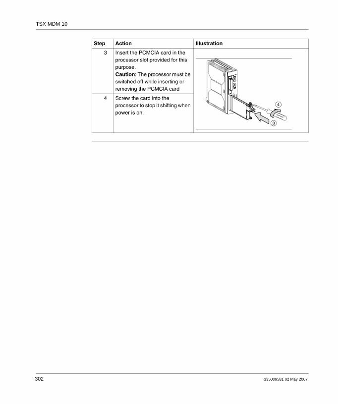
TSX MDM 10
3 Insert the PCMCIA card in the processor slot provided for this purpose.Caution: The processor must be switched off while inserting or removing the PCMCIA card
4 Screw the card into the processor to stop it shifting when power is on.
Step Action Illustration
302 335009581 02 May 2007

TSX MDM 10
12.4 Connecting adapters
Different adapters
At a Glance The telephone adapters, in line with the country of purchase, are used to ensure connection between an RJ 11 port of PCMCIA card TSX MDM 10 and the wall socket of the telephone network.To use the TSX MDM 10 card in a different country all you need to do is change the telephone adapter. List of adapter product references according to the country:
Country Product reference
Germany TSX MDM EDT G
Belgium TSX MDM EDT B
Spain TSX MDM EDT S
France TSX MDM EDT F
Italy TSX MDM EDT T
335009581 02 May 2007 303

TSX MDM 10
12.5 Electrical characteristics
Electrical characteristics
Consumption This table indicates the consumption of a PCMCIA modem card:
Voltage Typical current
5 volts 195 mA
304 335009581 02 May 2007

TSX MDM 10
12.6 Technical specifications
At a Glance
Aim of this Section
This Section deals with the technical specifications for the PCMCIA Modem card TSX MDM 10.
What's in this Section?
This section contains the following topics:
Topic Page
Communication protocols 306
Operating characteristics 307
Maximum operating temperature 308
EC labeling 309
335009581 02 May 2007 305
TSX MDM 10
Communication protocols
General The TSX MDM 10 card supports the various ITU-T V.32 communication protocols.
306 335009581 02 May 2007

TSX MDM 10
Operating characteristics
At a Glance The TSX MDM 10 card has the following characteristics: Sends AT commandsHalf and Full Duplex communicationAutomatic calls and repliesCalls by pulses or tones
335009581 02 May 2007 307
TSX MDM 10
Maximum operating temperature
Values Without ventilation module TSX FAN... : 50° C max.With ventilation module TSX FAN... : 60° C max.
308 335009581 02 May 2007

TSX MDM 10
EC labeling
General Card TSX MDM 10 conforms to the European Telecommunications Directive DTTC 98/13/EC.
Guaranteed level of immunity to electromagnetic fields: 3 V/m.Communication faults may appear beyond this threshold (in compliance with Directive CEM 89/336/EEC, applicable in residential and business areas, and areas of light industry.)
Card TSX MDM 10 also complies with the Low Voltage Directive 73/23 EEC, updated by 93/68/EEC.
335009581 02 May 2007 309

TSX MDM 10
310 335009581 02 May 2007

CBAIndex
AAS-i Bus Diagnostics, 104, 137
CCharacteristics
AS-i bus, 88Terminal port, 48TSX SAY 100, 100
characteristicsAS-i V2 bus, 122TSX SAY 1000, 133
CommunicationCharacter string, 25Man-machine interface console, 22UNI-TELWAY master/slave, 24With terminal, 21
ConnectionCharacter Mode, 174TSX FPP 10, 218TSX FPP 20, 217TSX MBP 100, 219TSX SAY 100, 93TSX SCA 50, 173TSX SCP 111, 193TSX SCP 112, 196TSX SCP 114, 208
connectionTSX SAY 1000, 128
Connection to the field busTSX SCY 11601, 169TSX SCY 21601, 169
35009581 02 May 2007
Connection to the TSX SCA 64 unit2-wire mode, 232
Connection to TSX SCA 64 unit4-wire mode, 233
ConsumptionTSX ETY 110, 276TSX FPP 10/20, 230TSX MBP 100, 230TSX MDM 10, 304TSX SCP 111, 230TSX SCP 112, 230TSX SCP 114, 230TSX SCY 11601, 175TSX SCY 21601, 175
consumptionTSX ETY 410•/PORT/510•, 289
IIntegrated FIPIO link
Premium/Atrium processors, 74
MMounting
PCMCIA, 187
PPair transmission configuration and polarization
2 wires with polarization of M+, M- pair by
311
Index
the master station or a slave station, 2544 wires with 2-pair polarization via external power supply, 2494 wires with one pair polarization by the master station, the other by a slave station, 251
PCMCIAVisual diagnostics, 190
Physical description of TSX SCA 64 device, 234
TTerminal port
Connector pin configuration, 50on Premium and Atrium, 19
Terminal Port connectionsModel 40 PLCs, 39Programming terminal, 28
Terminal port connections, 27Character string, 40Inter-device UNI-TELWAY, 38Man-machine interface console, 30Master UNI-TELWAY, 34Modem, 32Slave UNI-TELWAY, 35Summary table, 43UNI-TELWAY inter-PLC link, 36
TSX ETY 11010baseT interface, 273Connection by AUI interface, 270Diagnostics, 275Ethernet channel characteristics, 264Station address, 269
TSX ETY 410/PORT/510Ethernet Channel Characteristics, 280
TSX ETY 410•/510•diagnostics, 287
TSX ETY 410•/PORT/510•operating conditions, 291
TSX ETY 410•/PORT/TSX ETY 510•10/100baseT interface, 285
TSX MDM 10Telephone network connection, 301
312
TSX P ACC 01Connectable devices, 63Connecting to Premium/Atrium PLCs, 59Connection between 2 PLCs, 68Connector pin configuration, 61Dimensions, 56External appearance, 54Functionalities, 53Internal view, 57Switches, 60Uni-Telway Bus connection, 58UNI-TELWAY master, 65UNI-TELWAY slave, 67
TSX SAY 100Display, 97I/O addressing, 102Operating modes, 110Physical presentation, 91
TSX SAY 1000display, 131I/O addressing, 135operating modes, 138physical introduction, 126
TSX SCA 64Cable Template, 242cabling principles, 241Dimensions, 236installation, 238Line end adaptation, 256Mounting/Fixing, 236
TSX SCA 64 connection device, 231TSX SCY 11601
Built-in Channel Specifications, 156Description, 153Installation, 158Operation, 160Visual Diagnostics, 161
TSX SCY 21601Built-in Channel Specifications, 156Description, 153Host Channel Compatibility, 157Installation, 158Operation, 160Uni-Telway bus Connection, 165Visual Diagnostics, 161
35009581 02 May 2007