modicon m340, magelis altivar a nd preventa system user … systemow automatyki tl2007/… · mb -...
TRANSCRIPT
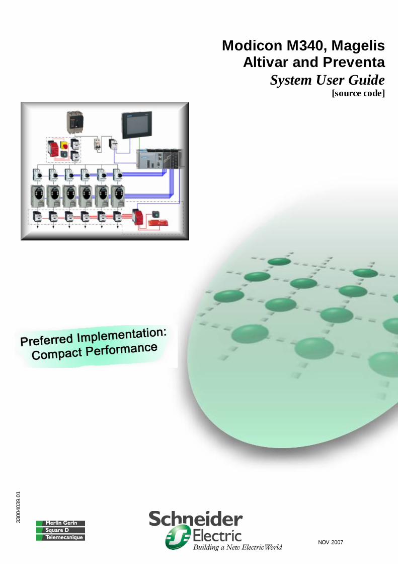
Modicon M340, Magelis Altivar and Preventa
System User Guide [source code]
3300
4039
.01
NOV 2007
M340 and Magelis Altivar and Preventa_EN.doc Schneider Electric 2
Contents
Introduction............................................................................................................................................2
Abbreviations.........................................................................................................................................3 Glossary .................................................................................................................................................4
Application Source Code.....................................................................................................................5 Typical Applications..............................................................................................................................6
System.....................................................................................................................................................7
Architecture............................................................................................................................................7 Installation............................................................................................................................................10
Hardware ...............................................................................................................................................15 Software ................................................................................................................................................21 Communication ......................................................................................................................................22
Implementation....................................................................................................................................27 Communication ......................................................................................................................................29 PLC.......................................................................................................................................................31 HMI .......................................................................................................................................................45 Devices..................................................................................................................................................56
Altivar ATV31 ......................................................................................................................................56 PowerSuite ..........................................................................................................................................64
Performance ..........................................................................................................................................68 Appendix...............................................................................................................................................69
Detailled Component List ..................................................................................................................69 Component Protection Classes........................................................................................................70
Component Features .........................................................................................................................71 Contact..................................................................................................................................................75
Introduction
Intention This document is intended to provide a quick introduction to the described System.
It is not intended to replace any specific product documentation. On the contrary, it offers additional information to the product documentation, for installing, configuring and starting up the system. The architecture described in this document is not a specific product in the normal commercial sense. It describes an example of how Schneider-Electric and third-party components may be integrated to fulfil an industrial application. A detailed functional description or the specification for a specific user application is not part of this document. Nevertheless, the document outlines some typical applications where the system might be implemented.

M340 and Magelis Altivar and Preventa_EN.doc Schneider Electric 3
Abbreviations
Abbreviation Signification
AC Alternating Current CB Circuit Breaker CFC Continuous Function Chart – a programming language based on
function chart DI Digital Input DO Digital Output DC Direct Current DFB Derived Function Blocks EDS Electronic Data Sheet E-OFF, E-STOP Emergency Off switch / Emergency Stop FBD Function Block Diagram – an IEC-61131 programming language HMI Human Machine Interface I/O Input/Output IL Instruction List - a textual IEC-61131 programming language IP Internet Protocol LD Ladder Diagram – a graphic IEC-61131 programming language MBTCP Communications protocol with Modbus over TCP (Ethernet) MFB PLCopen Motion Function Block PC Personal Computer POU Programmable Object Unit, Program Section in CoDeSys and
ELOP II Factory PDO Process Data Object (CANopen) PLC Programmable Logic Computer PS Power Supply RFID Radio Frequency IDentification RTU Remote Terminal Unit RPDO Receive Process Data Object (CANopen) SE Schneider Electric SFC Sequential Function Chart – an IEC-61131 programming language SDO Service Data Object ST Structured Text – an IEC-61131 programming language SRS PLC-Rack-Slot; Addressing system in ELOP II Factory TCP Transmission Control Protocol TPDO Transmit Process Data Object (CANopen) UDP User Data Protocol VSD Variable Speed Drive WxHxD Dimensions : Width, Height and Depth
M340 and Magelis Altivar and Preventa_EN.doc Schneider Electric 4
Glossary
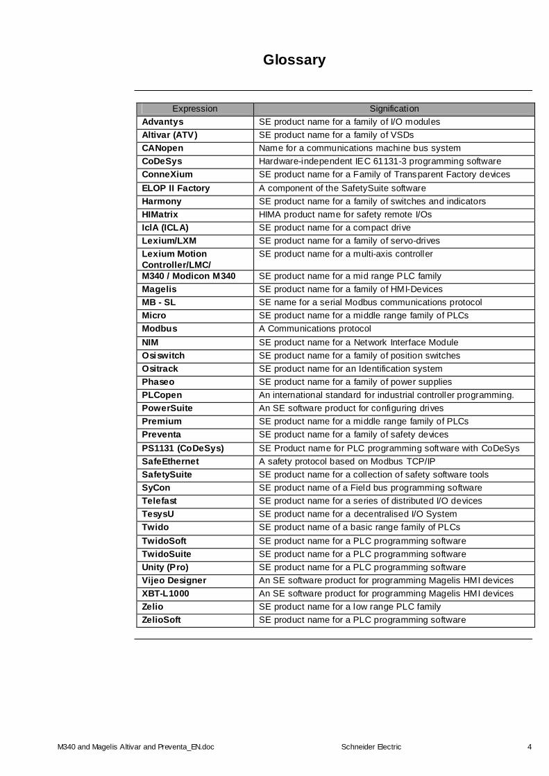
Expression Signification
Advantys SE product name for a family of I/O modules Altivar (ATV) SE product name for a family of VSDs CANopen Name for a communications machine bus system CoDeSys Hardware-independent IEC 61131-3 programming software ConneXium SE product name for a Family of Transparent Factory devices ELOP II Factory A component of the SafetySuite software Harmony SE product name for a family of switches and indicators HIMatrix HIMA product name for safety remote I/Os IclA (ICLA) SE product name for a compact drive Lexium/LXM SE product name for a family of servo-drives Lexium Motion Controller/LMC/
SE product name for a multi-axis controller
M340 / Modicon M340 SE product name for a mid range PLC family Magelis SE product name for a family of HMI-Devices MB - SL SE name for a serial Modbus communications protocol Micro SE product name for a middle range family of PLCs Modbus A Communications protocol NIM SE product name for a Network Interface Module Osiswitch SE product name for a family of position switches Ositrack SE product name for an Identification system Phaseo SE product name for a family of power supplies PLCopen An international standard for industrial controller programming. PowerSuite An SE software product for configuring drives Premium SE product name for a middle range family of PLCs Preventa SE product name for a family of safety devices PS1131 (CoDeSys) SE Product name for PLC programming software with CoDeSys SafeEthernet A safety protocol based on Modbus TCP/IP SafetySuite SE product name for a collection of safety software tools SyCon SE product name of a Field bus programming software Telefast SE product name for a series of distributed I/O devices TesysU SE product name for a decentralised I/O System Twido SE product name of a basic range family of PLCs TwidoSoft SE product name for a PLC programming software TwidoSuite SE product name for a PLC programming software Unity (Pro) SE product name for a PLC programming software Vijeo Designer An SE software product for programming Magelis HMI devices XBT-L1000 An SE software product for programming Magelis HMI devices Zelio SE product name for a low range PLC family ZelioSoft SE product name for a PLC programming software
M340 and Magelis Altivar and Preventa_EN.doc Schneider Electric 5
Application Source Code
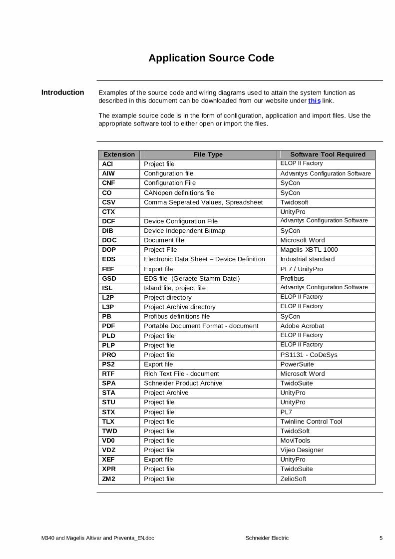
Introduction Examples of the source code and wiring diagrams used to attain the system function as
described in this document can be downloaded from our website under this link. The example source code is in the form of configuration, application and import files. Use the appropriate software tool to either open or import the files.
Extension File Type Software Tool Required ACI Project file ELOP II Factory
AIW Configuration file Advantys Configuration Software CNF Configuration File SyCon CO CANopen definitions file SyCon CSV Comma Seperated Values, Spreadsheet Twidosoft CTX UnityPro DCF Device Configuration File Advantys Configuration Software
DIB Device Independent Bitmap SyCon DOC Document file Microsoft Word DOP Project File Magelis XBTL 1000 EDS Electronic Data Sheet – Device Definition Industrial standard FEF Export file PL7 / UnityPro GSD EDS file (Geraete Stamm Datei) Profibus ISL Island file, project file Advantys Configuration Software L2P Project directory ELOP II Factory
L3P Project Archive directory ELOP II Factory PB Profibus definitions file SyCon PDF Portable Document Format - document Adobe Acrobat PLD Project file ELOP II Factory PLP Project file ELOP II Factory PRO Project file PS1131 - CoDeSys PS2 Export file PowerSuite RTF Rich Text File - document Microsoft Word SPA Schneider Product Archive TwidoSuite STA Project Archive UnityPro STU Project file UnityPro STX Project file PL7 TLX Project file Twinline Control Tool TWD Project file TwidoSoft VD0 Project file MoviTools VDZ Project file Vijeo Designer XEF Export file UnityPro XPR Project file TwidoSuite ZM2 Project file ZelioSoft
M340 and Magelis Altivar and Preventa_EN.doc Schneider Electric 6
Typical Applications
Introduction Here you will find a list of the typical applications where this system/subsystem can
be applied: Industrial Small to middle sized automated machines Packaging, Textile, Conveying, Services (water and waste treatment) automated autonomous sub systems serving as components to large or middle
sized machines Building HVAC Industrial & Technical Building Machines Packaging Specialised machines Conveying; Moving
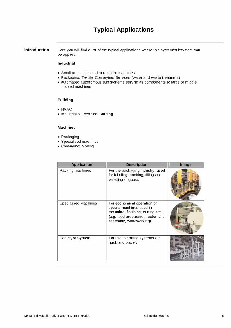
Application Description Image Packing machines For the packaging industry, used
for labeling, packing, filling and paletting of goods.
Specialised Machines For economical operation of
special machines used in mounting, finishing, cutting etc. (e.g. food preparation, automatic assembly, woodworking)
Conveyor System For use in sorting systems e.g. "pick and place".
M340 and Magelis Altivar and Preventa_EN.doc Schneider Electric 7
System
Introduction The system chapter describes the architecture, the dimensions, the quantities and different
types of components used within this system.
Architecture
General The system consists of a mid-range PLC controlling up to 6 variable speed drives that
can be controlled with 2 fixed speeds. Each drive has its own circuit breaker, each motor its own contactor. The drives are re-configured for this application. The configuration can be done using the PowerSuite software. The 400 VAC three phase input is split at the mains switch for the standard 400 VAC 3 phase system and a 230 VAC input to the automation hardware. All drives are hardwired into the PLC. Supervision of the drives is via a full graphics HMI touch screen configured and programmed using the VijeoDesigner software. The HMI control panel is connected to the PLC using a serial Modbus bus. The PLC is configured and programmed using UnityPro software. The software application in this example is only a minimum control application for using the drives with their factory setup. The hardware, however, has been selected with the intention of processing additional I/O. Options: The system has a category 2 safety level option with Preventa module supervised contactors for the drives. This safety module not only protects the drives but is also invoked by the emergency stop. The system has a second option of a category 3 safety level supervision for automatic stoppage of the motors if any of their enclosures are opened. This gives an overall category 3 safety level for the system. The options are shown in the layout diagrams in dotted line rectangles. Note: The Preventa safety module for the VSDs has its own power supply. In the case of a safety event, the safety modules must be acknowledged before the system can be reset or restarted.

M340 and Magelis Altivar and Preventa_EN.doc Schneider Electric 8
Layout
Components Hardware:
Master switch Compact NS100 Phaseo power supply (PS) Modicon M340 (PLC) Magelis XBT-GT (HMI) Variable speed drive Altivar 31 (VSD) 3 phase induction motor Optionale Hardware: Preventa safety module contactors Software: UnityPro (PLC) Vijeo Designer (HMI) PowerSuite (VSD)
M340 and Magelis Altivar and Preventa_EN.doc Schneider Electric 9
Quantities of Components
For a complete and detailed list of components, the quantities required and the order numbers. Please refer to the components list at the rear of this document.
Degree of Protection
Not all the components in this configuration are designed to withstand the same environmental conditions. Some components may need additional protection, in the form of housings, depending on the environment in which you intend to use them. For environmental details of the individual components please refer to the list in the appendix of this document and the appropriate user manual.
Mains voltage 400V AC Power requirement ~ 2,5 kW Drive power rating 6x 0,18 kW Motor brake none Connection 5x 2,5mm² (L1, L2, L3, N, PE)
Technical Data
Safety Level Cat. 2 (optional)
Safety Notice The standard and level of safety you apply to your application is determined by your
system design and the overall extent to which your system may be a hazard to people and machinery. As there are no moving mechanical parts in this application example, category 2 (according to EN954-1) has been selected as an optional safety level. Whether or not the above safety category should be applied to your system should be ascertained with a proper risk analysis. This document is not comprehensive for any systems using the given architecture and does not absolve users of their duty to uphold the safety requirements with respect to the equipment used in their systems or of compliance with either national or international safety laws and regulations
Dimensions The compact size of the PLC, the power supply and the Altivars permit the use of a
compact housing of the size 800 x 1800 x 800 mm (WxHxD). The HMI unit is fitted with brackets for fixing into a cut-out in the front door of the housing. The 3 phase motors are installed on the machine(s).

M340 and Magelis Altivar and Preventa_EN.doc Schneider Electric 10
Installation
Introduction This chapter describes the steps necessary to set up the hardware and configure the
software required to fulfil the described function of the application.
Assembly Cabinet front

M340 and Magelis Altivar and Preventa_EN.doc Schneider Electric 11
Assembly Cabinet Rear
M340 and Magelis Altivar and Preventa_EN.doc Schneider Electric 12
Function PLC- Program / HMI Controls The user can supervise up to 6 Altivar drives using the full graphics display of the Magelis HMI. The drives are hardwired into the PLC. The PLC has a serial Modbus connection to the HMI. After switching on, once the Magelis HMI has connected to the PLC, it offers you a start-up screen showing the system architecture and selectors for the safety menu, the Altivar menus and the System menu for the HMI system parameters. The 3 Altivar menus each give you access to 2 drives for controlling and monitoring. You can now use the ON buttons to start or stop all or one of the motors and select the direction of rotation using the left or right buttons. Use the Fast/Slow buttons to select one of the fixed speeds. The status of the drives’ contactor, drive status and speed actual and set values are indicated with 2 lamps. After switching on at the mains, the system is in safe mode, i.e. the blue acknowledgement button must be pushed before the drives can be powered up and the motors can be started. Pressing the emergency stop (and triggering the safety module) causes the drives to stop. Note: The I/O listed below is a minimal set to test the system and motor hardware connections as shown in the architecture. They do not represent a comprehensive collection of I/O required for control and display in an industrial application. Optional: The optional safety functions implemented with the Preventa module include supervision of a redundant overload contactor for all the attached Altivar drives and also supervision of the doors to cabinets containing the motors (here represented by a single movement sensor). Should the door to a cabinet be opened the motors are all stopped immediately and an acknowledgement is required before restart is possible. Note, shut down of a single motor or the entire mechanical system, i.e. the occurrence of a safety event, does not stop the PLC. Once the safety system has been invoked by a safety event, an acknowledgement must be given before the system can be reset/restarted.
M340 and Magelis Altivar and Preventa_EN.doc Schneider Electric 13
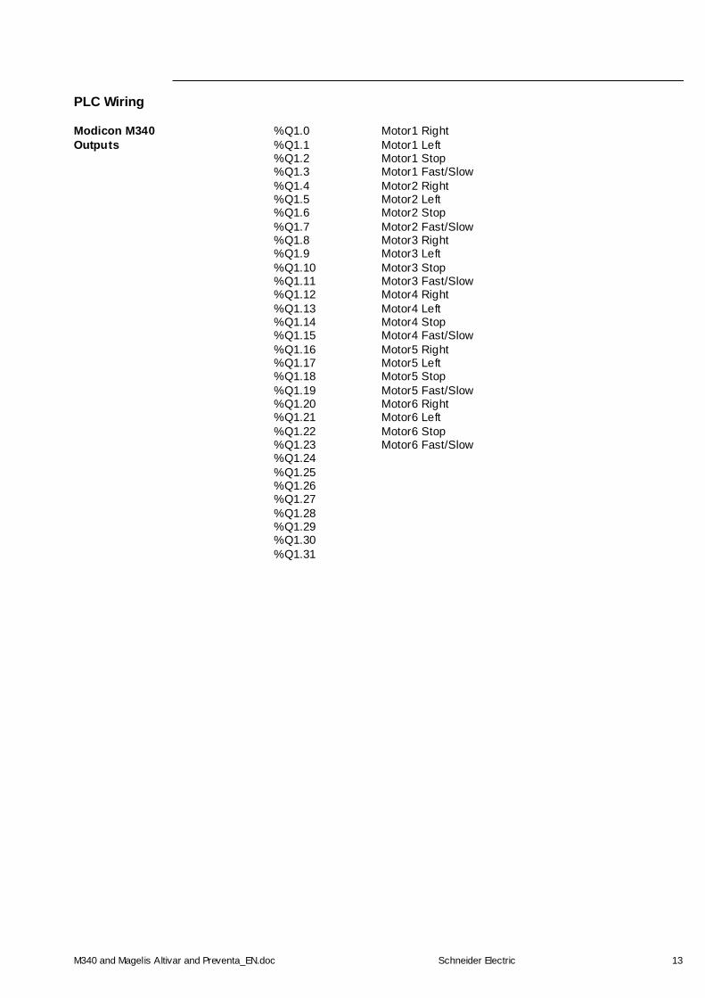
PLC Wiring
Modicon M340 Outputs
%Q1.0 %Q1.1 %Q1.2 %Q1.3 %Q1.4 %Q1.5 %Q1.6 %Q1.7 %Q1.8 %Q1.9 %Q1.10 %Q1.11 %Q1.12 %Q1.13 %Q1.14 %Q1.15 %Q1.16 %Q1.17 %Q1.18 %Q1.19 %Q1.20 %Q1.21 %Q1.22 %Q1.23 %Q1.24 %Q1.25 %Q1.26 %Q1.27 %Q1.28 %Q1.29 %Q1.30 %Q1.31
Motor1 Right Motor1 Left Motor1 Stop Motor1 Fast/Slow Motor2 Right Motor2 Left Motor2 Stop Motor2 Fast/Slow Motor3 Right Motor3 Left Motor3 Stop Motor3 Fast/Slow Motor4 Right Motor4 Left Motor4 Stop Motor4 Fast/Slow Motor5 Right Motor5 Left Motor5 Stop Motor5 Fast/Slow Motor6 Right Motor6 Left Motor6 Stop Motor6 Fast/Slow

M340 and Magelis Altivar and Preventa_EN.doc Schneider Electric 14
PLC Wiring Contd.
Modicon M340 Inputs
%I1.0 %I1.1 %I1.2 %I1.3 %I1.4 %I1.5 %I1.6 %I1.7 %I1.8 %I1.9 %I1.10 %I1.11 %I1.12 %I1.13 %I1.14 %I1.15 %I1.16 %I1.17 %I1.18 %I1.19 %I1.20 %I1.21 %I1.22 %I1.23 %I1.24 %I1.25 %I1.26 %I1.27 %I1.28 %I1.29 %I1.30 %I1.31
Motor1 FU Fault Motor1 Speed reached Motor1 MSS OK Motor2 FU Fault Motor2 Speed reached Motor2 MSS OK Motor3 FU Fault Motor3 Speed reached Motor3 MSS OK Motor4 FU Fault Motor4 Speed reached Motor4 MSS OK Motor5 FU Fault Motor5 Speed reached Motor5 MSS OK Motor6 FU Fault Motor6 Speed reached Motor6 MSS OK Plant OK
Modicon M340 Power Supply
24 VDC - +
0 V DC +24 V DC
M340 and Magelis Altivar and Preventa_EN.doc Schneider Electric 15
Hardware General The power supplies, fuses, contactors and circuit breakers require a DIN rail for
mounting. The HMI requires a cut-out in the housing door and can be fixed in place with the
brackets supplied with the Magelis unit. The motors can be mounted directly on the machine with a metal flange. 230 VAC wiring connects the master switch to the power supply. 400 VAC wiring connects the master switch to the contactors and drives. 24 VDC wiring connects the power supply to the PLC, the HMI, the acknowledgement
buttons, the warning lights and the safety modules.
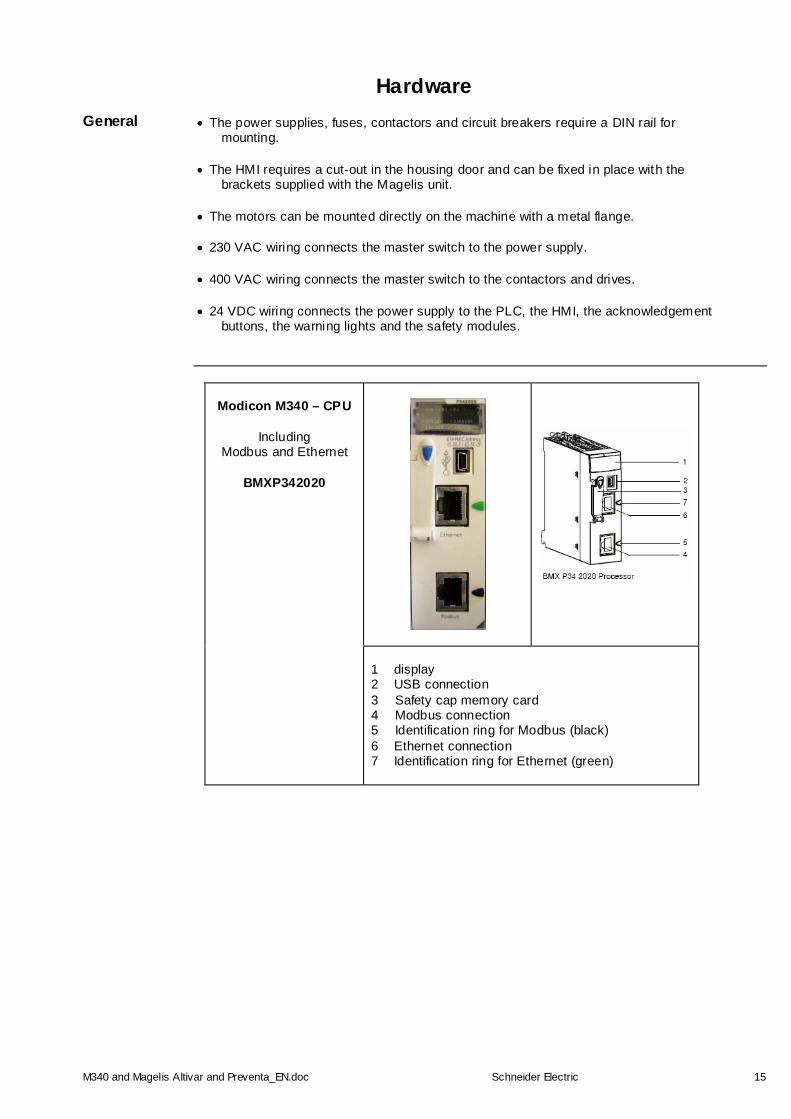
Modicon M340 – CPU
Including
Modbus and Ethernet
BMXP342020
1 display 2 USB connection 3 Safety cap memory card 4 Modbus connection 5 Identification ring for Modbus (black) 6 Ethernet connection 7 Identification ring for Ethernet (green)
M340 and Magelis Altivar and Preventa_EN.doc Schneider Electric 16
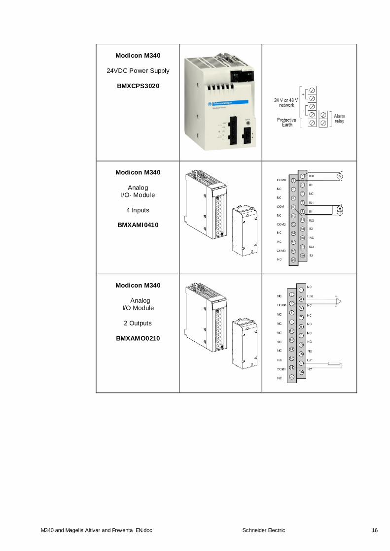
Modicon M340
24VDC Power Supply
BMXCPS3020
Modicon M340
Analog
I/O- Module
4 Inputs
BMXAMI0410
Modicon M340
Analog
I/O Module
2 Outputs
BMXAMO0210

M340 and Magelis Altivar and Preventa_EN.doc Schneider Electric 17
Modicon M340
Digital
I/O module for Telefast
32 Inputs
BMXDDI3202K
32 Outputs BMXDDO3202K
16 In- / 16 Out-puts
BMXDDM3202K
Telefast for 16 I/Os
ABE7H16R21
Connection Cable BMXFCC303
Use the connection cable to connect up 2 I/O blocks to an I/O module.
16 inputs
16 Outputs
Emergency OFF Switch
(trigger action)
XALK178G
M340 and Magelis Altivar and Preventa_EN.doc Schneider Electric 18
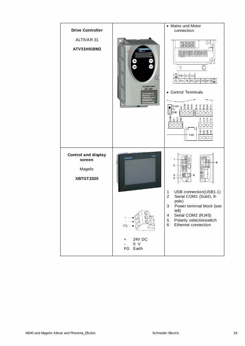
Drive Controller
ALTIVAR 31
ATV31H018M2
Mains und Motor connection
Control Terminals
Control and display
screen
Magelis
XBTGT2330
+ 24V DC - 0 V
FG Earth
1 USB connection(USB1.1) 2 Serial COM1 (SubD, 9-
pole) 3 Power terminal block (see
left) 4 Serial COM2 (RJ45) 5 Polarity selectionswitch 6 Ethernet connection

M340 and Magelis Altivar and Preventa_EN.doc Schneider Electric 19
Power Supply
ABL7RE2410
Master Switch
Compact NS100N

M340 and Magelis Altivar and Preventa_EN.doc Schneider Electric 20
Circuit Breaker
TeSys
GV2 Lxx
Contactor
TeSys
LC1 Dxx
Preventa
Safety Module
XPSAF5130
Preventa
E-STOP
Expansion Module
XPSECP5131
M340 and Magelis Altivar and Preventa_EN.doc Schneider Electric 21
Software
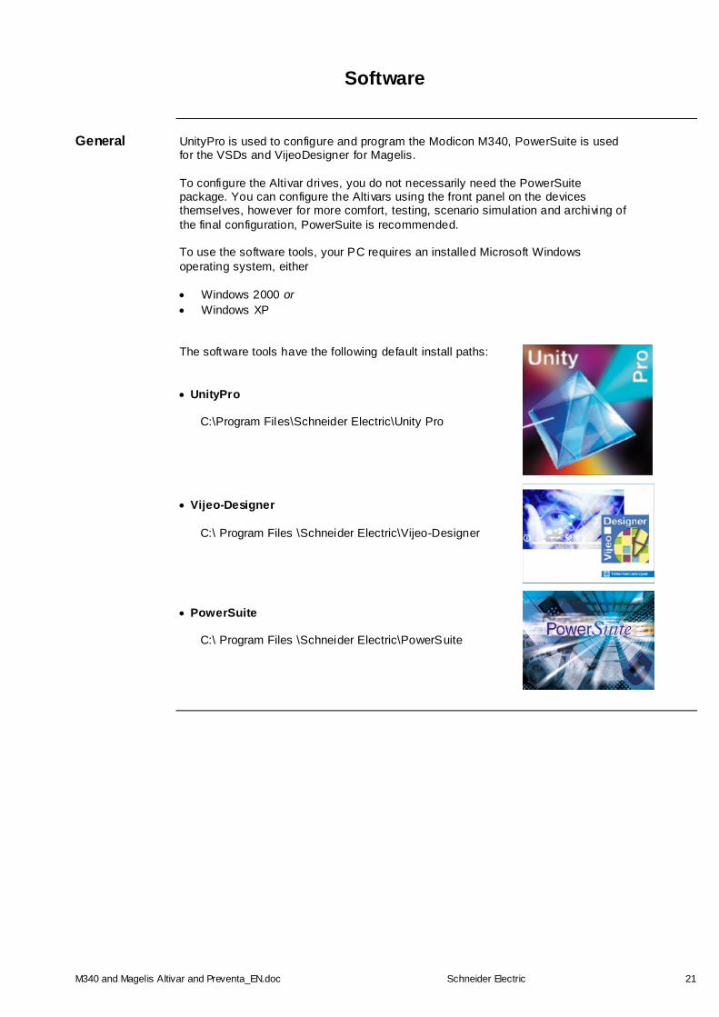
General UnityPro is used to configure and program the Modicon M340, PowerSuite is used
for the VSDs and VijeoDesigner for Magelis. To configure the Altivar drives, you do not necessarily need the PowerSuite package. You can configure the Altivars using the front panel on the devices themselves, however for more comfort, testing, scenario simulation and archiving of the final configuration, PowerSuite is recommended. To use the software tools, your PC requires an installed Microsoft Windows operating system, either Windows 2000 or Windows XP
The software tools have the following default install paths: UnityPro C:\Program Files\Schneider Electric\Unity Pro
Vijeo-Designer C:\ Program Files \Schneider Electric\Vijeo-Designer
PowerSuite C:\ Program Files \Schneider Electric\PowerSuite

M340 and Magelis Altivar and Preventa_EN.doc Schneider Electric 22
Communication
General The architecture presented here requires no bus system, however, the
communication between the PLC and the full graphics touchpanel Magelis (HMI) is established using Modbus protocol. Use the Modbus socket on the PLC for this. Option: Use Ethernet for the data transfer between the Modicon M340 PLC and the remote Magelis XBTGT HMI. You can also use this connection to download the application software from your PC to the PLC and HMI.
Modicon M340
CPU including Modbus
and Ethernet
BMXP342020
2 USB connection
4 Modbus connection 6 Ethernet connection
The MAC-Address is on the front of the CPU module below the display
M340 and Magelis Altivar and Preventa_EN.doc Schneider Electric 23
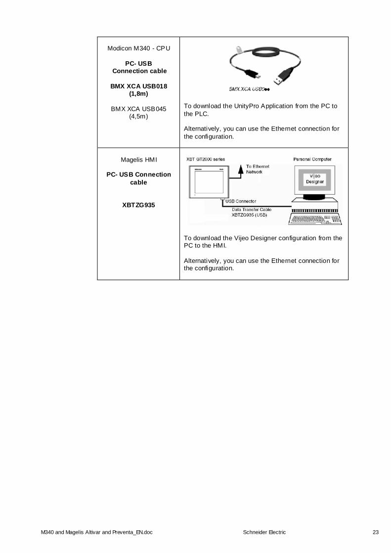
Modicon M340 - CPU
PC- USB
Connection cable
BMX XCA USB018 (1,8m)
BMX XCA USB045
(4,5m)
To download the UnityPro Application from the PC to the PLC. Alternatively, you can use the Ethernet connection for the configuration.
Magelis HMI
PC- USB Connection
cable
XBTZG935
To download the Vijeo Designer configuration from the PC to the HMI. Alternatively, you can use the Ethernet connection for the configuration.

M340 and Magelis Altivar and Preventa_EN.doc Schneider Electric 24
Altivar 31
PC – Serial Connection
Cable
VW3A8106
For connecting the PLC with the ATV31 VSDs when using the PowerSuite software.
ConneXium Ethernet Switch
5 Port
499NES25100
Option: only used for configuration

M340 and Magelis Altivar and Preventa_EN.doc Schneider Electric 25
Modicon M340
CPU including Modbus
and Ethernet
BMX P34 2020 Use the two dials on the rear of the module to set the IP address. The labels on the side of the module show how to use the dials.
This application uses the the IP address in the Unity project. For this, set up the dials as follows: Upper: 0 (dial is not needed). Lower: C or D (PLC configuration provides IP-address)
Magelis
XBTGT 2330
Modbus connection (RJ45)
for data transfer to/from
the PLC.
Magelis Modbus Kabel for communication between PLC and HMI
VW3A8306R30

M340 and Magelis Altivar and Preventa_EN.doc Schneider Electric 26
Download to the HMI Magelis XBT-GT2330
Connect the PC to the magelis via: PC Ethernet Connection HMI Ethernet Connection ConneXium Ethernet -
Cable
490 NTW 000 0x

M340 and Magelis Altivar and Preventa_EN.doc Schneider Electric 27
Implementation
Introduction The implementation chapter describes all the steps necessary to initialise, to configure, to
program and start-up the system to achieve the application functions as listed below.
Summary
Function A short user description
Communication How to set up the communication with memory reservation and variable names.
PLC Describes the configuration of the PLC with UnityPro.
HMI How to create the HMI application
Devices Describes how to configure the drive controllers.
Function Functional Description PLC Program / HMI-Display 1. After switching on at master switch, the safety monitoring system must first be
acknowledged and the individual power supply to the drives switched on. As soon as the HMI makes a connection with the PLC, the drives can be supervised via the HMI screens. Use the appropriate HMI menu to set the Altivar VSDs in RUN mode.
2. After start-up the drives are in manual mode. This mode allows the user to
access the state machine and to start and stop the drives individually. The HMI screens allow the user to start, stop and reverse the rotation of drives
note: The speed (RPM) of the motors is set at a constant value. This value can only be changed via the user panel on the drive itself.
M340 and Magelis Altivar and Preventa_EN.doc Schneider Electric 28
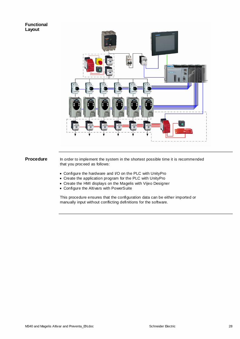
Functional Layout
Procedure In order to implement the system in the shortest possible time it is recommended
that you proceed as follows: Configure the hardware and I/O on the PLC with UnityPro Create the application program for the PLC with UnityPro Create the HMI displays on the Magelis with Vijeo Designer Configure the Altivars with PowerSuite This procedure ensures that the configuration data can be either imported or manually input without conflicting definitions for the software.

M340 and Magelis Altivar and Preventa_EN.doc Schneider Electric 29
Communication
Introduction This chapter describes the data passed via the communications bus (e.g. Modbus
Plus or TCP/IP) that is not bound directly with digital or analog hardware. The list contains: The device links Direction of the data flow The symbolic name The Bus address of the device concerned.
Device Links
The described architecture is a hardwired system as far as the device (VSDs) connections to the PLC are concerned. However for the data transfer between the HMI device and the PLC, this application uses Modbus. Modbus connects: - a Modicon M340-PLC as Bus-Slave, Bus address 1 - a Magelis XBTGT HMI as Bus-Master,
Modbus Data direction HMI PLC HMI <> PLC Device Start address Reserved Memory Address summary SPS HMI %MW100 %MW100…106 HMI SPS %MW200 %MW200...206

M340 and Magelis Altivar and Preventa_EN.doc Schneider Electric 30
The PLC and HMI applications use various hardware addresses and memory bits and words. The following lists explains the types used and the address column not only shows the format but the address ranges used.
Type Address Comment
Digital Inputs %Ir.m.x -r: 0 -m: 2…4 -x: 0…15
PLC: Digital inputs are hardware orientated: r as rack number, m as slot number, x as Input number.
Digital Outputs %Qr.m.x -r: 0 -m: 5…6 -x: 0…15
PLC: Digital outputs are hardware orientated: r as rack number, m as slot number, x as output number
Analog Inputs %IWr.m.c -r: 0 -m: 7 -c: 0…3
PLC: Analog inputs are hardware orientated: r as rack number, m as Slot number, c as channel number
Analog Outputs %QWr.m.c -r: 0 -m: 8 -c: 0…1
PLC: Analog outputs are hardware orientated: r as rack number, m as Slot number, c as channel number.
Memory words %MWx -x Wort
PLC and HMI: Memory words are used to transfer data between the PLC and HMI. The range depends on the PLC. Max. 32463. Used:0…9999
Bits %Mx -x Wort
PLC and HMI: Bits are used to transfer data between the PLC and HMI. The range depends on the PLC. Max. 32633. Used:0…9999
Derived Memory Words
%MWx.y %MWx:Xy -x Wort -y Bit
PLC and HMI: The elements (Bits) of the Memory words are used to transfer data between the PLC and HMI. The range depends on the PLC. Max. 32633. Used: 0…9999. Bit numbering: 0…15.
different addressing formats PLC %MW100.1 Bit 1 from MW100 HMI %MW100:X1 Bit 1 from MW100
Address Summary PLC and HMI
Status Modbus %CHr.m.c -r: 0 -m: 0 -c:
PLC: Status of the Modbus is read into the data structure T_COM_MB_BMX (an IODDT).
Channel addr.: r as Rack number, m as Slot number, c as channel number. Status Modbus %CH0.0.2

M340 and Magelis Altivar and Preventa_EN.doc Schneider Electric 31
PLC
Introduction The PLC chapter describes the steps required for the initialisation and configuration
and the source program required to fulfil the functions.
Requirements Before carrying out the steps described below, you must ensure the following: The Unity Pro programming software is installed on your PC. The Modicon M340 PLC is connected to the power supply. The PLC and the PC are connected to one another via the programming cable
(BMXXCAUSB0xx) or Ethernet (with a known IP address). Setting up the PLC is done as follows: Create new program and select hardware Configure the Modbus Configure the Ethernet Creating Variables Program breakdown Build project Download project. Export and archive project.
Create new program and select hardware
1 To create a new program, select: File->New…
2 A window opens where you can
select the CPU to be used. For this application, select the Modicon M340 CPU BMX P34 2020 and click OK to confirm. This will load the default settings.
3 Double-click or right-click on the rack in the project browser and select: Open.

M340 and Magelis Altivar and Preventa_EN.doc Schneider Electric 32
4 This will open the rack display and the Hardware catalog. To fill out the rack, simply select the individual components and drag and drop them to empty slots in the rack. The following hardware is used: Rack BMX XBP 0800 Power BMX CPS 3020 CPU BMX P34 2020 32DI BMX DDI 3202K 32DI BMX DDI 3202K 32DI BMX DDI 3202K 32DO BMX DDO 3202K 32DO BMX DDO 3202K 4AI BMX AMI 0410 2AO BMX AMO 0210
5 The display shown opposite shows the final set up.
6 This is what the rack looks like
in the project browser.
7 At this point, it is recommended
that you save the project. To do this, select File->Save As… In the save dialog you can then define the File name (<File name>.stu) and the location where the file is to be saved under Save in. Click OK to save and exit.
M340 and Magelis Altivar and Preventa_EN.doc Schneider Electric 33
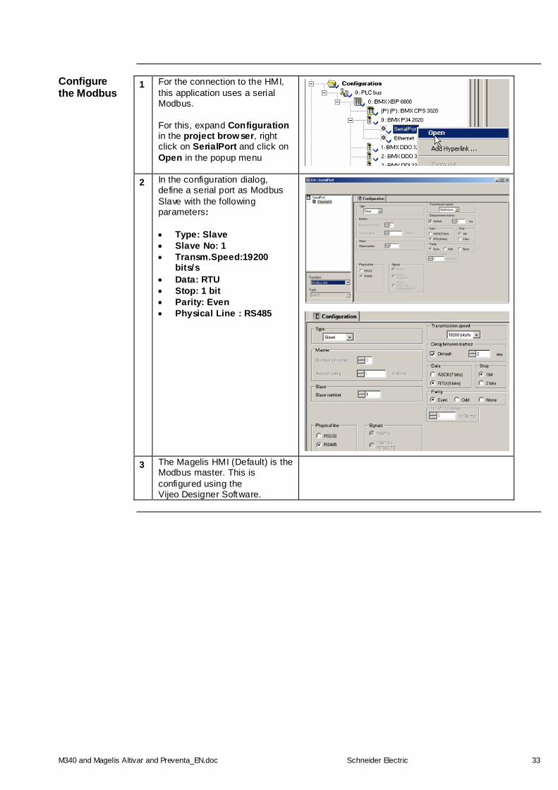
Configure the Modbus
1 For the connection to the HMI, this application uses a serial Modbus. For this, expand Configuration in the project brow ser, right click on SerialPort and click on Open in the popup menu
2 In the configuration dialog, define a serial port as Modbus Slave with the following parameters: Type: Slave Slave No: 1 Transm.Speed:19200
bits/s Data: RTU Stop: 1 bit Parity: Even Physical Line : RS485
3 The Magelis HMI (Default) is the
Modbus master. This is configured using the Vijeo Designer Software.

M340 and Magelis Altivar and Preventa_EN.doc Schneider Electric 34
Configure the Ethernet
1 An Ethernet connection is configured in this application for connection to a PC or SCADA system. For Ethernet, you need to create a new network. To do this, right-click Networks in the Communication entry and select New Network….
2 Select Ethernet from the list of networks in the window that appears.
3 A name must also be entered.
You are free to choose any name, but in this example, ETH is used. Click OK to confirm.
4 Open the configuration window
by right-clicking ETH and selecting Open.
M340 and Magelis Altivar and Preventa_EN.doc Schneider Electric 35
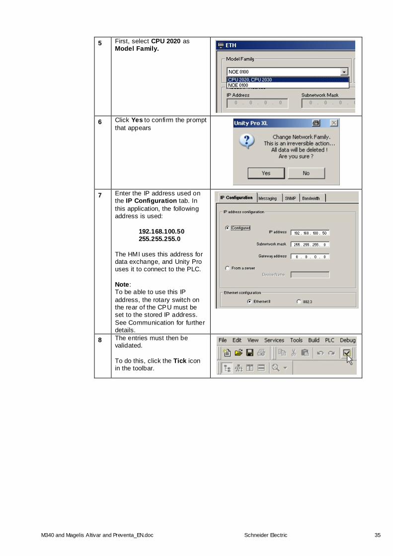
5 First, select CPU 2020 as Model Family.
6 Click Yes to confirm the prompt
that appears
7 Enter the IP address used on
the IP Configuration tab. In this application, the following address is used: 192.168.100.50 255.255.255.0 The HMI uses this address for data exchange, and Unity Pro uses it to connect to the PLC. Note: To be able to use this IP address, the rotary switch on the rear of the CPU must be set to the stored IP address. See Communication for further details.
8 The entries must then be validated. To do this, click the Tick icon in the toolbar.
M340 and Magelis Altivar and Preventa_EN.doc Schneider Electric 36
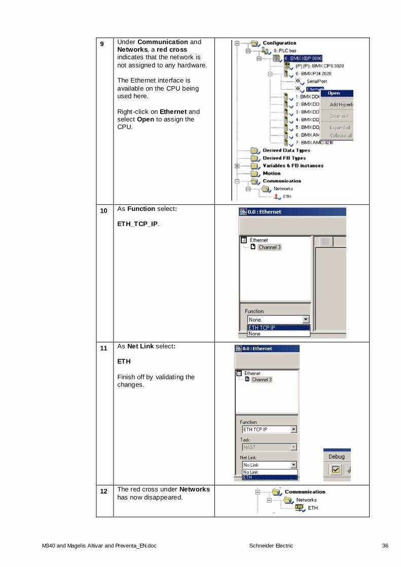
9 Under Communication and Networks, a red cross indicates that the network is not assigned to any hardware. The Ethernet interface is available on the CPU being used here. Right-click on Ethernet and select Open to assign the CPU.
10 As Function select:
ETH_TCP_IP.
11 As Net Link select:
ETH Finish off by validating the changes.
12 The red cross under Networks
has now disappeared.
M340 and Magelis Altivar and Preventa_EN.doc Schneider Electric 37
Creating Variables
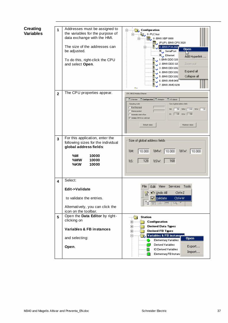
1 Addresses must be assigned to the variables for the purpose of data exchange with the HMI. The size of the addresses can be adjusted. To do this, right-click the CPU and select Open.
2 The CPU properties appear.
3 For this application, enter the
following sizes for the individual global address fields: %M 10000 %MW 10000 %KW 10000
4 Select:
Edit->Validate to validate the entries. Alternatively, you can click the icon on the toolbar.
5 Open the Data Editor by right-clicking on Variables & FB instances and selecting: Open.
M340 and Magelis Altivar and Preventa_EN.doc Schneider Electric 38
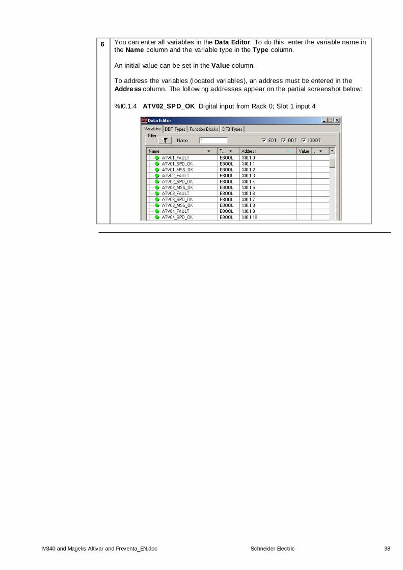
6 You can enter all variables in the Data Editor. To do this, enter the variable name in the Name column and the variable type in the Type column. An initial value can be set in the Value column. To address the variables (located variables), an address must be entered in the Address column. The following addresses appear on the partial screenshot below: %I0.1.4 ATV02_SPD_OK Digital input from Rack 0; Slot 1 input 4

M340 and Magelis Altivar and Preventa_EN.doc Schneider Electric 39
Program Breakdown
1 The individual program sections are displayed under Program in the project brow ser.
2 Here is a brief summary:
Init Consists of the functions that must be carried out when the application program is started (e.g., initialise variables).
Signalisation Evaluation of the operational modes
Safety_Control Analyses the information provided by the safety controller.
ATV_Control This section is responsible for controlling the drives.
HMI_Control This section is responsible fort he data transfer between the HMI and PLC
Building a Project
1 A project must be analyzed and compiled before it can be transferred to the PLC. To do this, select Build and Rebuild All Project in the menu bar. Alternatively, click on the appropriate icon in the toolbar.
2 Click Yes to confirm the message that follows.
3 The project is analysed and the
code generated.

M340 and Magelis Altivar and Preventa_EN.doc Schneider Electric 40
4 Once this is complete, the number of errors and warnings is displayed. A box displaying Built can also be seen in the status bar of the Unity window.
Download Project
1 To establish a connection to the PLC, Standard Mode must first be activated.
2 If the PLC is connected to the
PC via the USB cable, an icon indicating this is displayed in the PC status bar. The Modicon M340 – BMX CPU is displayed in the Windows screen.
3 Select PLC->Set Address to set the address.
4 The following parameters are set for a USB connection: Address: SYS Media: USB
5 These entries can be tested
directly. To do this, click Test Connection on the right-hand side. A message window will appear to indicate that connection has been successful. Click OK to confirm. Close the Set Address dialog by clicking OK.

M340 and Magelis Altivar and Preventa_EN.doc Schneider Electric 41
6 In Unity Pro, the mode of connection that has been selected is displayed in the status bar at the bottom.
7 Select: PLC->Connect to connect to the PLC.
8 The status bar shows that the PLC status is set to RUN and that the program on the PC and the one in the PLC are DIFFERENT.
9 Select: PLC->Transfer Project to PLC to download the project.
10 Both the PC and PLC projects,
along with their version and date, are displayed in the window that opens next. Click Transfer to start the download process.
11 To download, any project running on the PLC must be stopped. Click OK to continue.
12 The project is transferred and
initialised.
13 The status bar shows that the
PC and PLC program are now the same (EQUAL), but that the PLC it is still in STOP mode.
M340 and Magelis Altivar and Preventa_EN.doc Schneider Electric 42
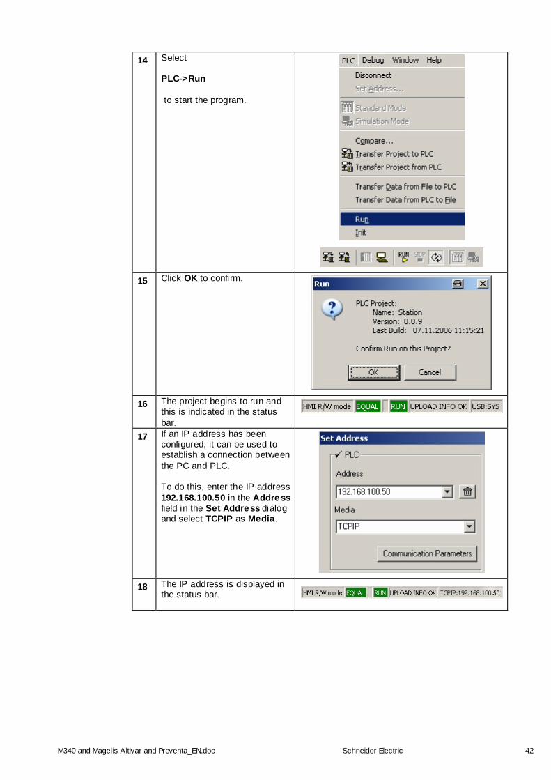
14 Select PLC->Run to start the program.
15 Click OK to confirm.
16 The project begins to run and
this is indicated in the status bar.
17 If an IP address has been configured, it can be used to establish a connection between the PC and PLC. To do this, enter the IP address 192.168.100.50 in the Address field in the Set Address dialog and select TCPIP as Media.
18 The IP address is displayed in
the status bar.
M340 and Magelis Altivar and Preventa_EN.doc Schneider Electric 43
Exporting and Archiving a Project
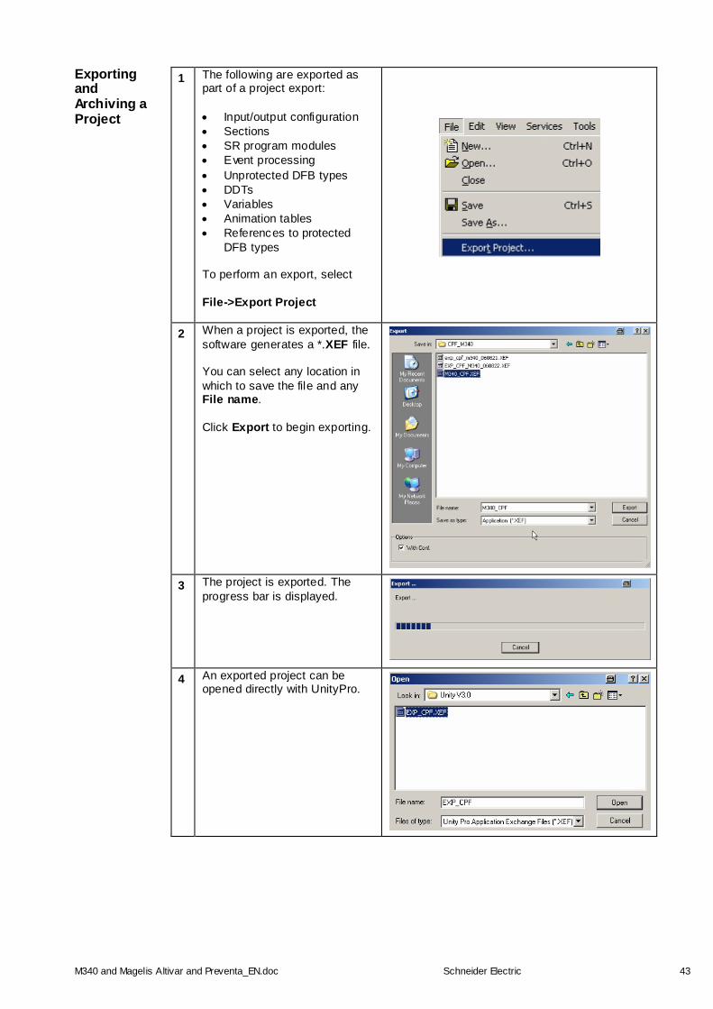
1 The following are exported as part of a project export: Input/output configuration Sections SR program modules Event processing Unprotected DFB types DDTs Variables Animation tables References to protected
DFB types To perform an export, select File->Export Project
2 When a project is exported, the software generates a *.XEF file. You can select any location in which to save the file and any File name. Click Export to begin exporting.
3 The project is exported. The
progress bar is displayed.
4 An exported project can be opened directly with UnityPro.
M340 and Magelis Altivar and Preventa_EN.doc Schneider Electric 44
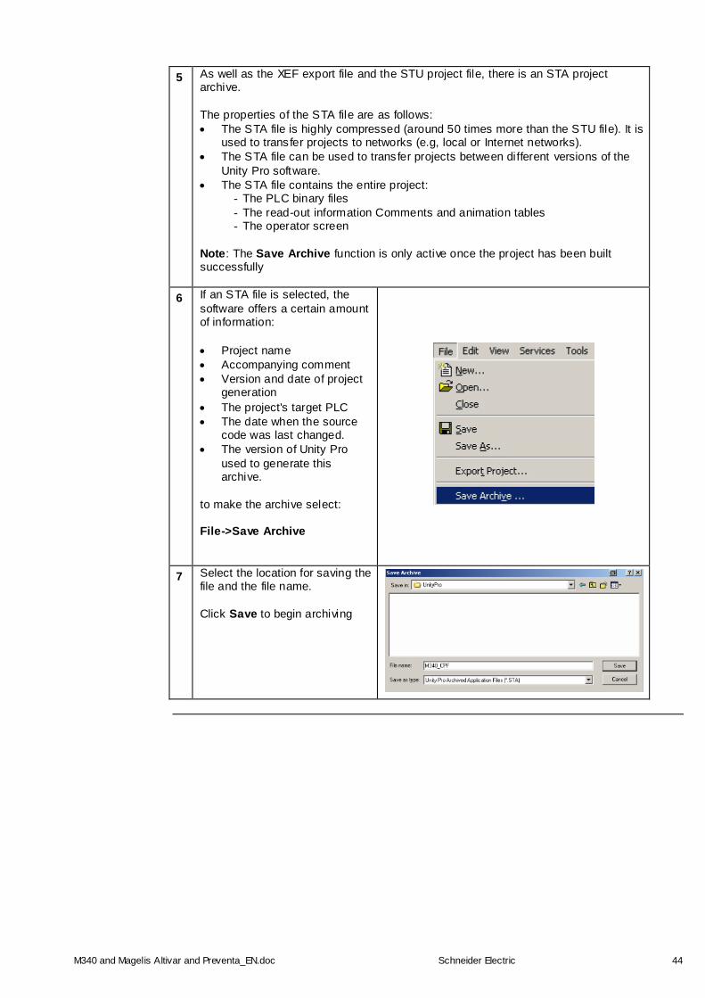
5 As well as the XEF export file and the STU project file, there is an STA project archive. The properties of the STA file are as follows: The STA file is highly compressed (around 50 times more than the STU file). It is
used to transfer projects to networks (e.g, local or Internet networks). The STA file can be used to transfer projects between different versions of the
Unity Pro software. The STA file contains the entire project:
- The PLC binary files - The read-out information Comments and animation tables - The operator screen
Note: The Save Archive function is only active once the project has been built successfully
6 If an STA file is selected, the software offers a certain amount of information: Project name Accompanying comment Version and date of project
generation The project's target PLC The date when the source
code was last changed. The version of Unity Pro
used to generate this archive.
to make the archive select: File->Save Archive
7 Select the location for saving the file and the file name. Click Save to begin archiving

M340 and Magelis Altivar and Preventa_EN.doc Schneider Electric 45
HMI
Introduction
This application features a Magelis XBT-GT 2330 HMI, which is connected to the PLC via the Modbus protocol. Vijeo Designer software is used to program and configure the terminal. The steps to be taken in order to create and download a program are described on the pages that follow. Setting up the HMI is done as follows: Vijeo Designer function overview Create new project (specify plat form, hardware, communication). Communication settings Creating variables Create screens Check the project download project Application overview
Function Overview
1 Vijeo Designer has the following components:
1 - Navigator 2 - Info-Display 3 - Inspector 4 - Data list 5 - Feedback Zone 6 - Toolbox
Creating a New Project
1 After starting Vijeo Designer, a new project can be created. To do this, select, File->New Project in the menu bar.
M340 and Magelis Altivar and Preventa_EN.doc Schneider Electric 46
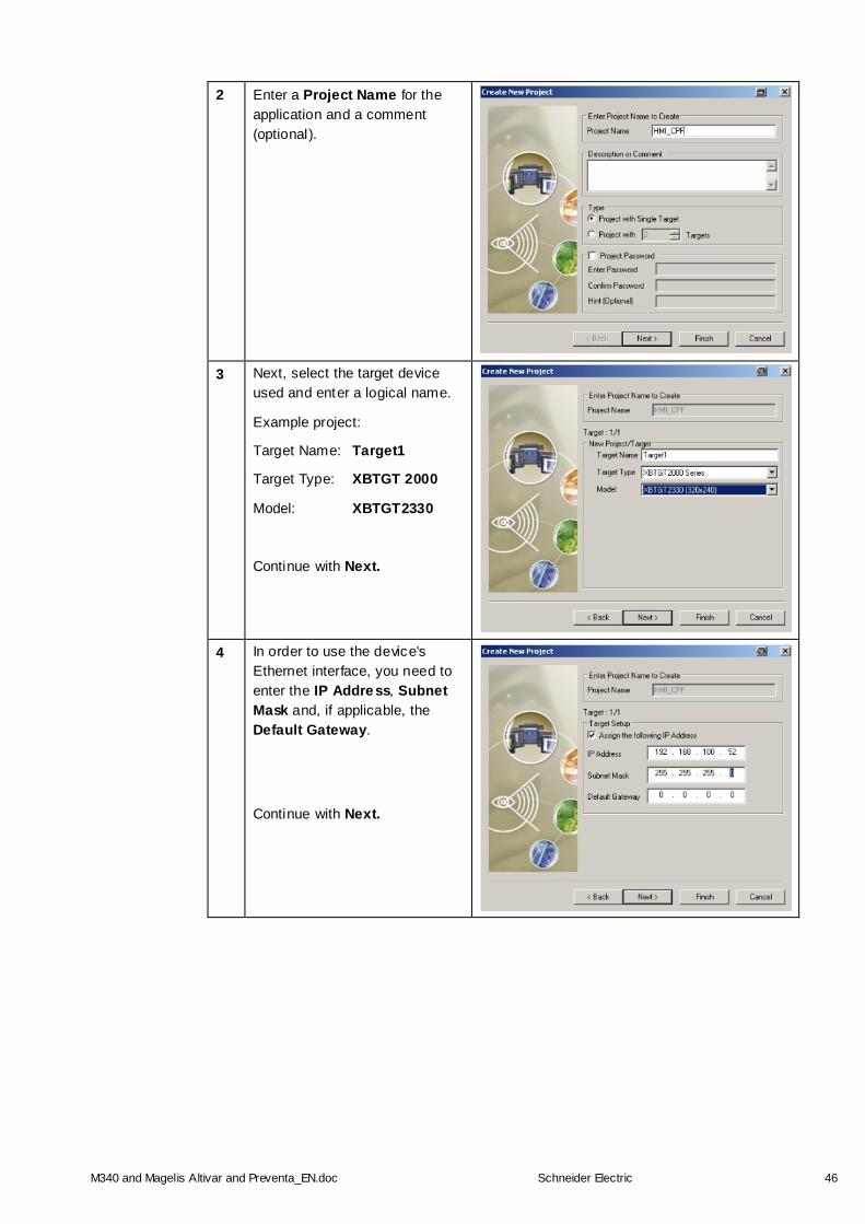
2 Enter a Project Name for the application and a comment (optional).
3 Next, select the target device used and enter a logical name.
Example project:
Target Name: Target1
Target Type: XBTGT 2000
Model: XBTGT2330
Continue with Next.
4 In order to use the device's Ethernet interface, you need to enter the IP Address, Subnet Mask and, if applicable, the Default Gateway.
Continue with Next.
M340 and Magelis Altivar and Preventa_EN.doc Schneider Electric 47
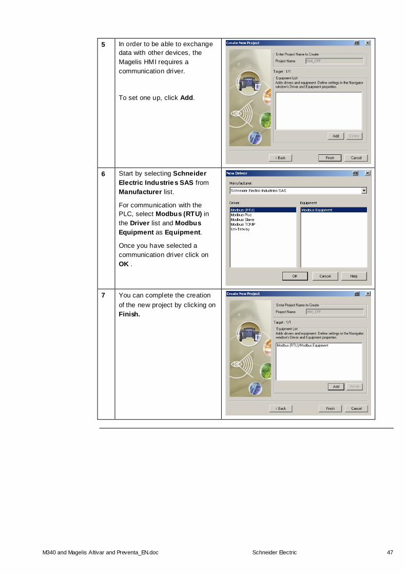
5 In order to be able to exchange data with other devices, the Magelis HMI requires a communication driver.
To set one up, click Add.
6 Start by selecting Schneider Electric Industries SAS from Manufacturer list.
For communication with the PLC, select Modbus (RTU) in the Driver list and Modbus Equipment as Equipment.
Once you have selected a communication driver click on OK .
7 You can complete the creation of the new project by clicking on Finish.

M340 and Magelis Altivar and Preventa_EN.doc Schneider Electric 48
Communi-cation Settings
1 Once you have created the project, Vijeo Designer will display the workspace described above with an empty edit screen on the right-hand side.
2 For the HMI you must set up the Modbus with the MB-Address and the COM interface used.
Do this under IO Manager in the Navigator, on the tab Project.
3 To communicate with the PLC, the interface parameters must be defined for the Modbus (RTU) driver.
Right mouse-click on ModbusRTU01 and select Configuration….
4 Select COM Port COM2 (RS485 über RJ45)
with the Parameters:
Trans Speed 19200 kbit/s
Parity Bit Even
Stop Bit 1
Data Length 8
and confirm with OK .
Note: The Modbus parameters must correspond to the Modbus setup in the PLC.

M340 and Magelis Altivar and Preventa_EN.doc Schneider Electric 49
Creating Variables
1 To create new variables in the Navigator, select the Variable tab at the bottom of the screen.
Right mouse click on the project name (here Target) displays a Popup-menu.
Click on New VariableNew..
2 To create variables, the Variable Properties must be defined:
Variable Name Data Type Data Source (External) Device Address in the PLC
3 All memory types on the PLC can be addressed.
Memory Bits (%M or %MW:xi) Memory Words (%MW) Double words (%MD), Floating point (%MF), System bits (%S) System words (%SW), Constant bits (%K) Constant words (%KW). All data to be displayed on the viewer must be transferred to one of these types.

M340 and Magelis Altivar and Preventa_EN.doc Schneider Electric 50
4 You can also import/export variables.
To import the variables from UnityPro, in the tab Variables in the Navigator, right mouse click on the Target (here in the example Target1) to open up a popup menu and select the option:
Link Variables...
5 Enter/Select the Filename
Files of type: Unity (*.stu)
Equipment: PLC
and continue with Open
6 Select the variables you require by checking the checkbox next to them or click Select All for the complete list.
Select variables that keep the same name so that the PLC and HMI use the same names for the varaibles.
Click on Add to import the selected variables.
Now Close the dialog
M340 and Magelis Altivar and Preventa_EN.doc Schneider Electric 51
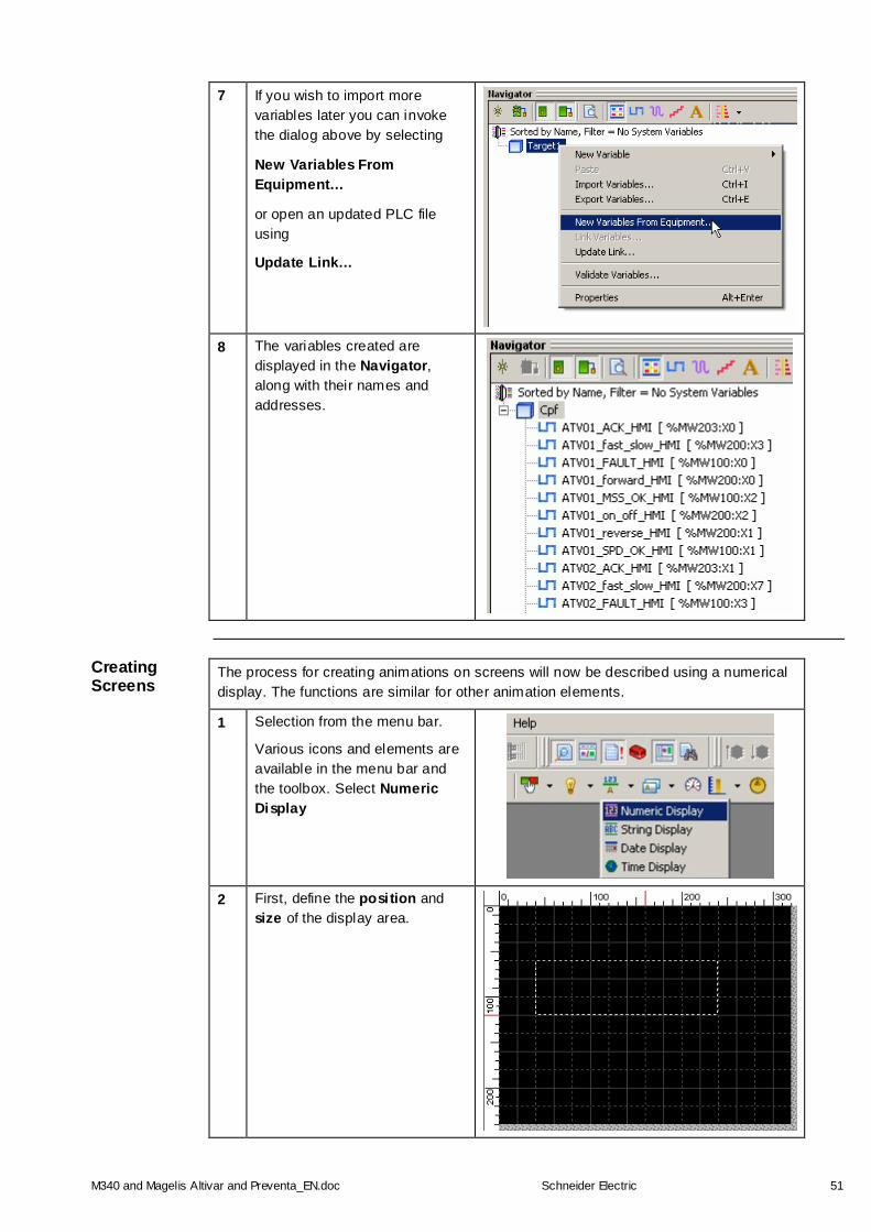
7 If you wish to import more variables later you can invoke the dialog above by selecting
New Variables From Equipment…
or open an updated PLC file using
Update Link…
8 The variables created are displayed in the Navigator, along with their names and addresses.
Creating Screens
The process for creating animations on screens will now be described using a numerical display. The functions are similar for other animation elements.
1 Selection from the menu bar.
Various icons and elements are available in the menu bar and the toolbox. Select Numeric Display
2 First, define the position and size of the display area.

M340 and Magelis Altivar and Preventa_EN.doc Schneider Electric 52
3 Numeric Display Settings:
Name Data Type Variable Display Format Font The variable can be entered directly or can be selected by means of the icon to the right of the field (light bulb).
Note:
A variable name that has been entered but not recognized appears in red.
4 The variable to be animated can be transferred from the list by double-clicking it.
Additional functions, e.g., value inversion, can be executed by clicking on the calculator icon.
M340 and Magelis Altivar and Preventa_EN.doc Schneider Electric 53
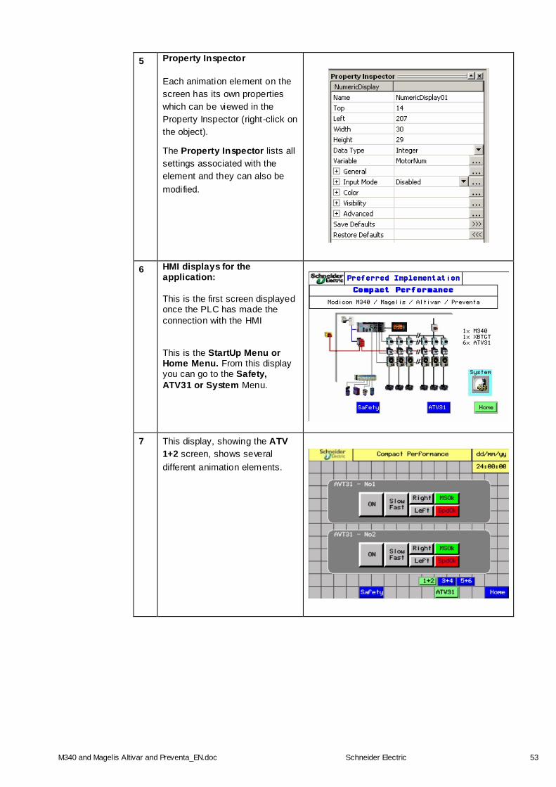
5 Property Inspector Each animation element on the screen has its own properties which can be viewed in the Property Inspector (right-click on the object).
The Property Inspector lists all settings associated with the element and they can also be modified.
6 HMI displays for the application: This is the first screen displayed once the PLC has made the connection with the HMI This is the StartUp Menu or Home Menu. From this display you can go to the Safety, ATV31 or System Menu.
7 This display, showing the ATV 1+2 screen, shows several different animation elements.

M340 and Magelis Altivar and Preventa_EN.doc Schneider Electric 54
8 Monitoring a single motor After selecting a drive a display appears indicating the actual status of the drive. The drive number appears at the top. Clicking ON and then Left or Right, starts the motor in that direction. The button changes its colour to green if the command was successful. Use SLOW/FAST to select one of two fixed speeds. Select 1+2, 3+4 oder 5+6 to display information about the other drives. Use the Home button to return to the Start menu
9 In the Safety Menu you can check the safety status. Use the Home button to return to the Start menu
Validate the Project
1 Before you download the project to the Magelis you must validate it With Validate All you can analyse your project. The feedback zone shows you the results of the analysis.

M340 and Magelis Altivar and Preventa_EN.doc Schneider Electric 55
2 If Build All is selected instead, the messages are still listed in the Feedback Zone.
.
Download the Project
1 Select Download All under Build to transfer the application to the connected Magelis terminal.
The configured method of communication (in this case, Ethernet) is used.
2 Assigning the Ethernet IP Address Unless the project has already been transferred using a USB cable, the HMI will not have the correct IP address. For this reason, the IP address must be entered via the offline setting mode before downloading takes place. This is done as follows: On powering up, touch the top left-hand corner of the screen. Alternatively, while the application is being executed, touch three corners of the
screen at the same time. (In the plat form properties of the Vijeo Designer Editor, you can select the procedure to be followed by your application.)
Next, enter the IP address. Switch back to online mode.

M340 and Magelis Altivar and Preventa_EN.doc Schneider Electric 56
Devices
Introduction This chapter describes the steps required to initialise and configure the devices to
attain the described system function.
The follwing devices are used: Variable Speed Drive Altivar 31
Altivar ATV31
Introduction This section describes how to configure the parameters for the Altivar VSD. You can
input the Altivar parameters using the programming panel on the device itself (optional). However, the big advantage of using PowerSuite is that you can store the data on your PC and also have the possibility to print and document this information. The software is also an aid to invoking the Altivar and optimising the parameters in online mode. NOTE: The factory settings in your version of PowerSuite may be different to those delivered on the actual device. If you wish to ensure that you start with the same base configuration on device and in PowerSuite, it is recommended that you upload the configuration from the Altivar before making any changes in the factory settings. If you change the settings on the Altivar, the factory settings can be restored by setting the FCS function in the control menu DRC using the front panel of the Altivar.
For the given example we use mainly the factory settings on the Altivar. The parameters in the list below, however, have to be changed as the connections are hardwired. You can view the parameters with their values using the front panel of the Altivar. Note: The ATV31’s are hardwired and directly connected to the PLC I/O terminals. The I/O allocation for the 6 Altivar ATV31s in our example is: Input ATV - LI1A Turn right Input ATV - LI2A Turn Left Input ATV - LI3A Stop Input ATV - LI4A Fast/Slow Output ATV - R1 Drive Fault Output ATV - R2 Speed reached
M340 and Magelis Altivar and Preventa_EN.doc Schneider Electric 57
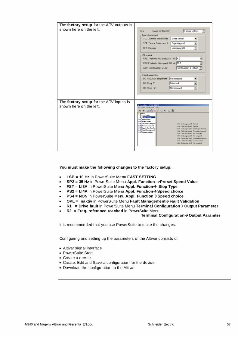
The factory setup for the ATV outputs is shown here on the left.
The factory setup for the ATV inputs is shown here on the left.
You must make the following changes to the factory setup: LSP = 10 Hz in PowerSuite Menu FAST SETTING SP2 = 35 Hz in PowerSuite Menu Appl. Function-->Preset Speed Value FST = LI3A in PowerSuite Menu Appl. Function Stop Type PS2 = LI4A in PowerSuite Menu Appl. FunctionSpeed choice PS4 = NON in PowerSuite Menu Appl. FunctionSpeed choice OPL = inaktiv in PowerSuite Menu Fault ManagementFault Validation R1 = Drive fault in PowerSuite Menu Terminal ConfigurationOutput Parameter R2 = Freq. reference reached in PowerSuite Menu Terminal ConfigurationOutput Paramter It is recommended that you use PowerSuite to make the changes.
Configuring and setting up the parameters of the Altivar consists of: Altivar signal interface PowerSuite Start Create a device Create, Edit and Save a configuration for the device Download the configuration to the Altivar

M340 and Magelis Altivar and Preventa_EN.doc Schneider Electric 58
Altivar Signal Interface
1 Layout of Altivar 31 RJ45-Interface. The RJ45-Connection is found behind the front panel of the Altivar and is the communications interface of the device. It is used for connecting the Altivar to a PC (i.e. with PowerSuite) or a hand held HMI device. You can use this interface to run the PowerSuite simulator.
2 Altivar
The Signal interface
3 Altivar Front Panel Functions
PowerSuite with ATV31
You can configure the Altivars using the configuration software PowerSuite.
1 After start up, select the folder Compact Performance (see the setup/user manual for PowerSuite).
M340 and Magelis Altivar and Preventa_EN.doc Schneider Electric 59
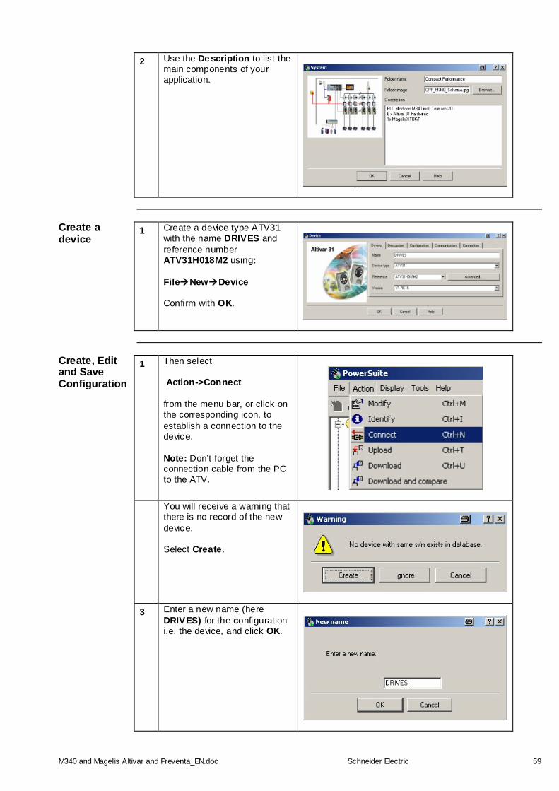
2 Use the Description to list the main components of your application.
Create a device
1 Create a device type ATV31 with the name DRIVES and reference number ATV31H018M2 using: FileNewDevice Confirm with OK.
Create, Edit and Save Configuration
1 Then select Action->Connect from the menu bar, or click on the corresponding icon, to establish a connection to the device. Note: Don’t forget the connection cable from the PC to the ATV.
You will receive a warning that there is no record of the new device. Select Create.
3 Enter a new name (here DRIVES) for the configuration i.e. the device, and click OK.

M340 and Magelis Altivar and Preventa_EN.doc Schneider Electric 60
4 A progress bar is displayed as the the data is read out from the Altivar 31.
5 Once the transfer is complete, the drive information will be displayed.
6 The parameters can be
displayed in list format or ..
M340 and Magelis Altivar and Preventa_EN.doc Schneider Electric 61
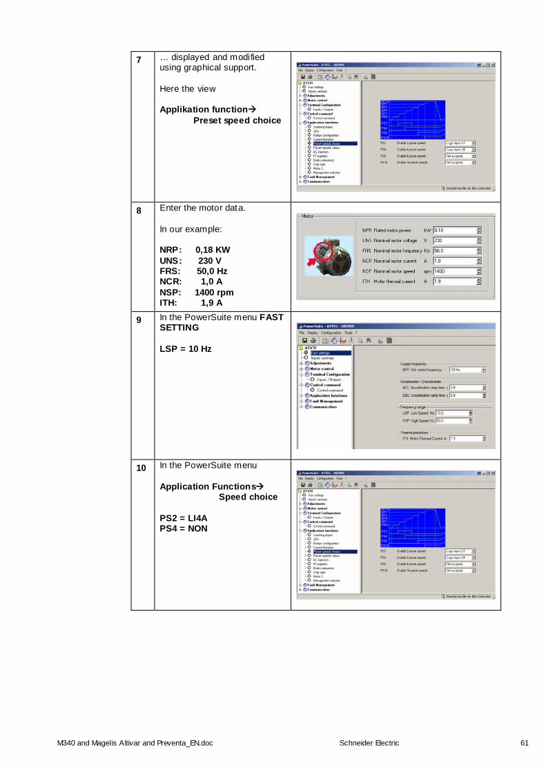
7 … displayed and modified using graphical support. Here the view Applikation function Preset speed choice
8 Enter the motor data. In our example: NRP: 0,18 KW UNS: 230 V FRS: 50,0 Hz NCR: 1,0 A NSP: 1400 rpm ITH: 1,9 A
9 In the PowerSuite menu FAST SETTING LSP = 10 Hz
10 In the PowerSuite menu Application Functions Speed choice PS2 = LI4A PS4 = NON

M340 and Magelis Altivar and Preventa_EN.doc Schneider Electric 62
11 In the PowerSuite menu Application Functions Stop Type FST = LI3A
12 In the PowerSuite menu Fault Management Fault Validation OPL = inaktiv
13 In Power Suite Menu Terminal Configuration Inputs/Outputs R1 = Drive fault R2 = Freq. reference reached
14 In the PowerSuite menu Application Functions-> Preset Speed Value SP2 = 35 Hz
15 Save the data with: FileSave As
M340 and Magelis Altivar and Preventa_EN.doc Schneider Electric 63
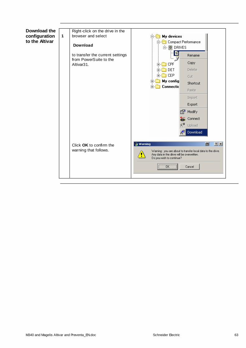
Download the configuration to the Altivar
1 Right-click on the drive in the browser and select Download to transfer the current settings from PowerSuite to the Altivar31. Click OK to confirm the warning that follows.
M340 and Magelis Altivar and Preventa_EN.doc Schneider Electric 64
PowerSuite
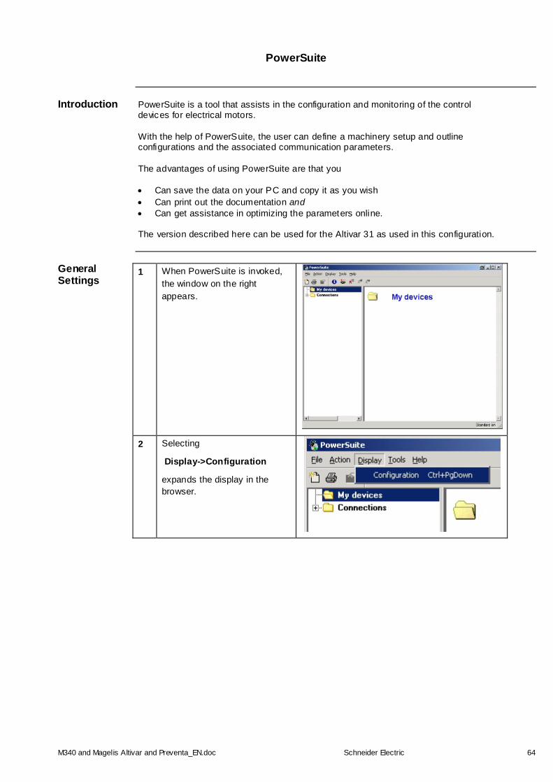
Introduction PowerSuite is a tool that assists in the configuration and monitoring of the control
devices for electrical motors. With the help of PowerSuite, the user can define a machinery setup and outline configurations and the associated communication parameters. The advantages of using PowerSuite are that you Can save the data on your PC and copy it as you wish Can print out the documentation and Can get assistance in optimizing the parameters online. The version described here can be used for the Altivar 31 as used in this configuration.
General Settings
1 When PowerSuite is invoked, the window on the right appears.
2 Selecting
Display->Configuration
expands the display in the browser.
M340 and Magelis Altivar and Preventa_EN.doc Schneider Electric 65
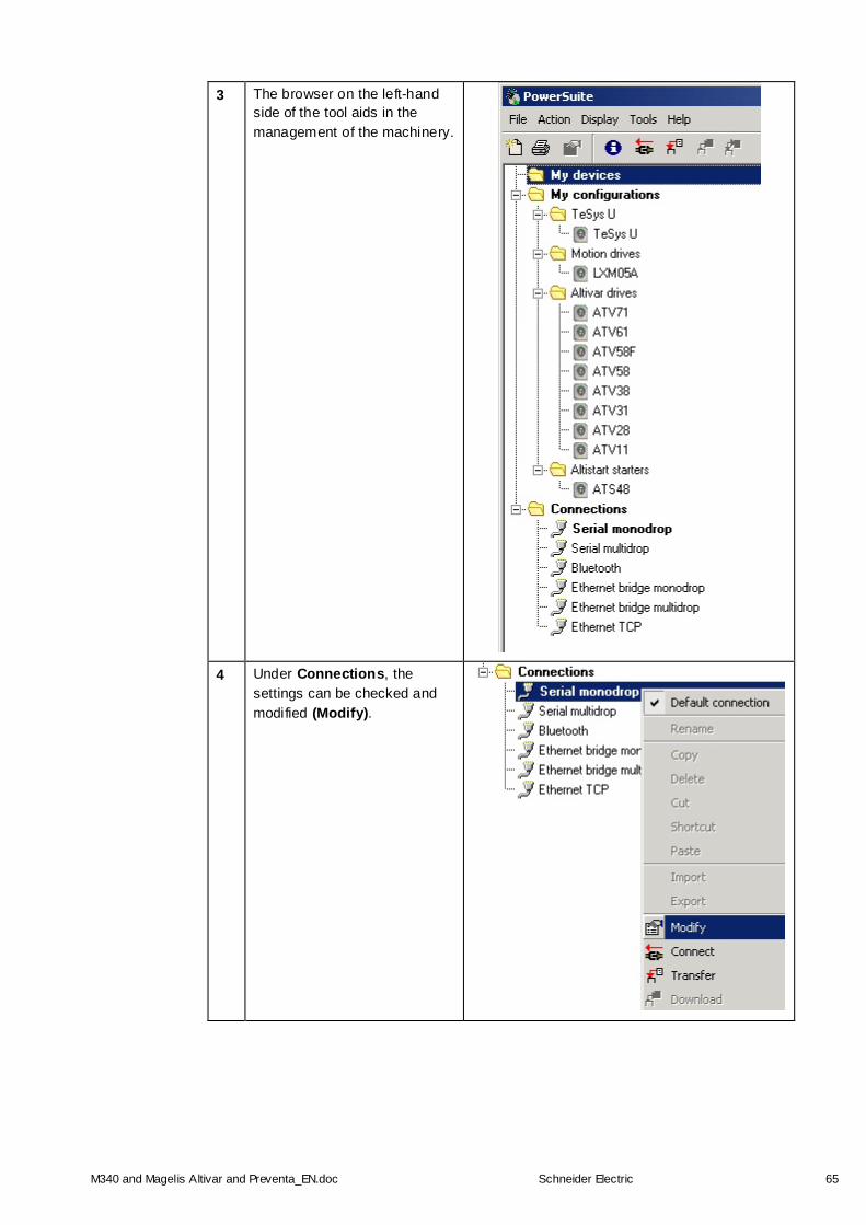
3 The browser on the left-hand side of the tool aids in the management of the machinery.
4 Under Connections, the settings can be checked and modified (Modify).

M340 and Magelis Altivar and Preventa_EN.doc Schneider Electric 66
5 Right-click on Serial monodrop and Modify to enter the serial COM interface that is being used (here COM1). Set the following: Communication Port: COM1 Baudrate: 19200 bauds Format : 8bits.no.1stp Click OK to confirm.
6 Selecting the connection displays the settings (as shown opposite).
7 In PowerSuite, it is possible to group the various drives into subfolders (e.g., according to the machine). To do this, select My devices.
8 Then select File->New->Folder
M340 and Magelis Altivar and Preventa_EN.doc Schneider Electric 67
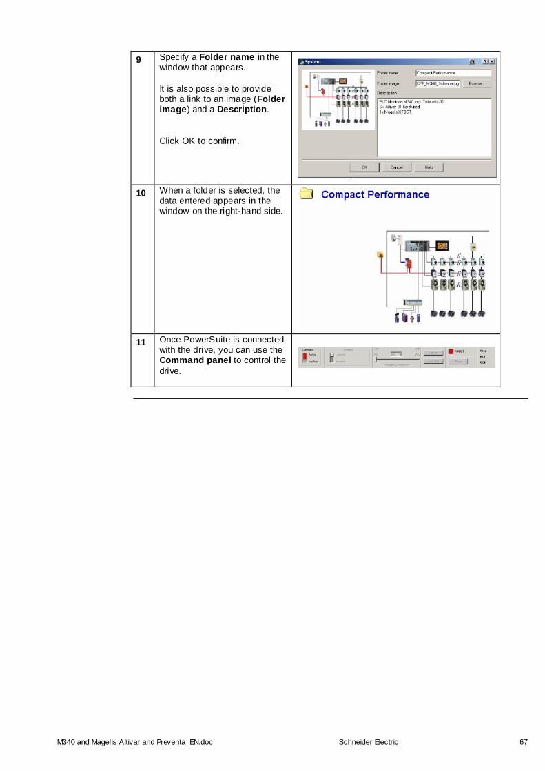
9 Specify a Folder name in the window that appears. It is also possible to provide both a link to an image (Folder image) and a Description. Click OK to confirm.
10 When a folder is selected, the data entered appears in the window on the right-hand side.
11 Once PowerSuite is connected with the drive, you can use the Command panel to control the drive.

M340 and Magelis Altivar and Preventa_EN.doc Schneider Electric 68
Performance
Scan and cycle time
A cycle time of 3 ms was not exceeded with this configuration, including the required application code. The memory utilization of the Controller specified and used in this SUG was 10% for system data and 6.5% for the program.

M340 and Magelis Altivar and Preventa_EN.doc Schneider Electric 69
Appendix
Detailled Component List
Hardware Components Pos. Amt. Description Part Number Rev./
Vers.
Power 1.01 1 Master Switch 3-pole 36kA NS100N 29003 1.02 1 trip block 29035 1.03 1 Terminal cover 29321 1.04 1 rotary drive 29340 1.05 1 Power supply 230/24VDC, 10A ABL7RP2410
PLC 2.01 1 PLC CPU with Modbus and Ethernet BMXP342020 V1.00-38 2.02 1 Rack with 8 Slots BMXXBP0800 2.03 1 Power supply BMXCPS3020 2.04 3 Digital Input module 32 channels BMXDDI3202K 2.05 2 Digital Output module 32 channels BMXDDO3202K 2.06 1 Analog input module 4 channels BMXAMI0410 2.07 1 Analog output module 2 channels BMXAMO0210 2.08 1 Telefast connection cable BMXFCC303 2.09 5 Telefast block 16 In- or 16 Out-puts ABE7H16R21 2.10 5 terminalblock 20 poles BMXFTB2020
HMI 3.01 1 circuit breaker 1 A (C60H 1P C) 25020 3.02 1 Magelis-Touchscreen terminal 5,7“
TFT Colour, Ethernet XBTG2330 SV1.1
Drives 4.01 6 Altivar31, 0.18kW, 230VAC single
phase ATV31H018M2 V1.7IE15
4.02 6 circuit breaker 2,5 A GV2L07 4.03 6 contactor LC1D09BD 4.04 6 Switch mounting GVAE11
Safety 5.01 1 E-off switch, trigger action XALK178G
5.02 1 Preventa-Safety module ESTOP Category 4
XPSAF5130
5.03 1 circuit breaker (1 A) 25020 5.04 1 Contactor LC1D32BD 5.05 1 acknowledge and warning switch XB5AW36B5
Ethernet 6.01 1 ConneXium Ethernet Switch 499NES25100
6.02 1 ConneXium Ethernet Cable, 2m 490NTW00002 6.03 1 ConneXium Ethernet Cable, 5m 490NTW00005
M340 and Magelis Altivar and Preventa_EN.doc Schneider Electric 70
Pos. Amt. Description Part Number Rev./ Vers.
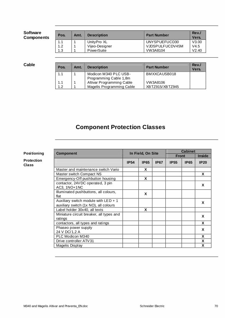
Software Components
1.1 1 UnityPro XL UNYSPUEFUCD30 V3.00 1.2 1 Vijeo-Designer VJDSPULFUCDV45M V4.5 1.3 1 PowerSuite VW3A8104 V2.40
Pos. Amt. Description Part Number Rev./ Vers.
Cable
1.1 1 Modicon M340 PLC USB-Programming Cable 1,8m
BMXXCAUSB018
1.1 1 Altivar Programming Cable VW3A8106 1.2 1 Magelis Programming Cable XBTZ915/XBTZ945
Component Protection Classes
Cabinet Positioning Component In Field, On Site Front Inside Protection Class
IP54 IP65 IP67 IP55 IP65 IP20
Master and maintenance switch Vario X Master switch Compact NS X Emergency-Off pushbutton housing X contactor, 24VDC operated, 3 pin
AC3, 1NO+1NC X
Illuminated pushbuttons, all colours, flat X
Auxiliary switch module with LED + 1 auxiliary switch (1x NO), all colours
X
Label holder 30x40, all texts X Miniature circuit breaker, all types and
ratings X
contactors, all types and ratings X Phaseo power supply
24 V DC/1,2 A X
PLC Modicon M340 X Drive controller ATV31 X Magelis Display X
M340 and Magelis Altivar and Preventa_EN.doc Schneider Electric 71
Component Features
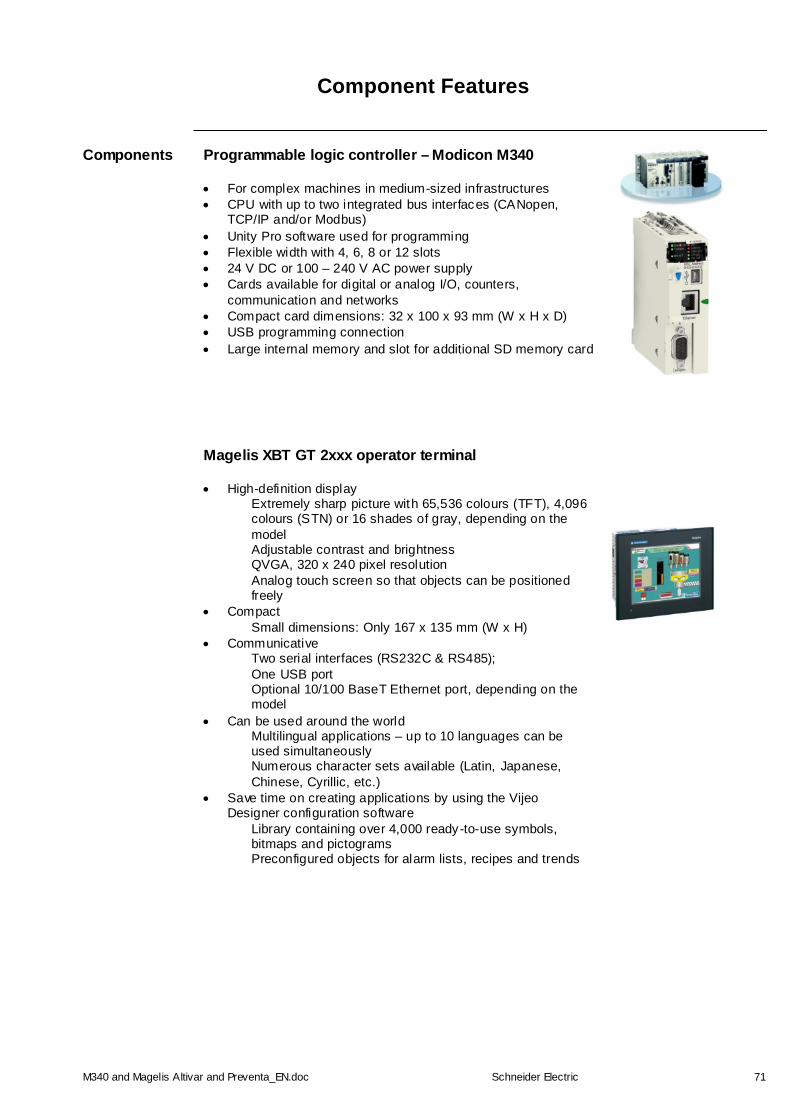
Components Programmable logic controller – Modicon M340
For complex machines in medium-sized infrastructures CPU with up to two integrated bus interfaces (CANopen,
TCP/IP and/or Modbus) Unity Pro software used for programming Flexible width with 4, 6, 8 or 12 slots 24 V DC or 100 – 240 V AC power supply Cards available for digital or analog I/O, counters,
communication and networks Compact card dimensions: 32 x 100 x 93 mm (W x H x D) USB programming connection Large internal memory and slot for additional SD memory card
Magelis XBT GT 2xxx operator terminal High-definition display
Extremely sharp picture with 65,536 colours (TFT), 4,096 colours (STN) or 16 shades of gray, depending on the model Adjustable contrast and brightness QVGA, 320 x 240 pixel resolution Analog touch screen so that objects can be positioned freely
Compact Small dimensions: Only 167 x 135 mm (W x H)
Communicative Two serial interfaces (RS232C & RS485); One USB port Optional 10/100 BaseT Ethernet port, depending on the model
Can be used around the world Multilingual applications – up to 10 languages can be used simultaneously Numerous character sets available (Latin, Japanese, Chinese, Cyrillic, etc.)
Save time on creating applications by using the Vijeo Designer configuration software
Library containing over 4,000 ready-to-use symbols, bitmaps and pictograms Preconfigured objects for alarm lists, recipes and trends
M340 and Magelis Altivar and Preventa_EN.doc Schneider Electric 72
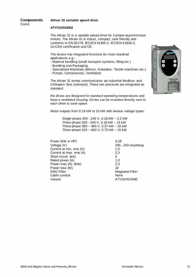
Components Contd.
Altivar 31 variable speed drive ATV31H018M2 The Altivar 31 is a variable speed drive for 3 phase asynchronous motors. The Altivar 31 is robust, compact, user friendly and conforms to EN 50178, IEC/EN 61800-2, IEC/EN 61800-3, UL/CSA-certi fication and CE. The device has integrated functions for most standrad applications e.g.: - Material handling (small transport systems, lifting etc.) - Bundling and Packaging - Specialised Machines (Mixers, Kneaders, Textile machines etc.) - Pumps, Compressors, Ventilators The Altivar 31 series communicates via industrial Modbus- and CANopen- Bus (onboard). These two protocols are integrated as standard. the drives are designed for standard operating temperatures and have a ventilated housing. Drives can be mounted directly next to each other to save space. Motor outputs from 0.18 kW to 15 kW with various voltage types:
Single-phase 200 - 240 V, 0.18 kW – 2.2 kW Three-phase 200 - 240 V, 0.18 kW – 15 kW Three-phase 380 – 480 V, 0.37 kW – 15 kW Three-phase 525 – 600 V, 0.75 kW – 15 kW
Power (kW or HP) 0,18 Voltage (V) 200...240 einphasig Current at min. revs (A) 1,5 Current at max. revs (A) 2,3 Short circuit (kA) 5 Rated power (A) 1,5 Power max (A), (60s) 2,3 Power loss (W) 32 EMC-Filter integrated Filter Cable conduit None Variant ATV31H018M2
M340 and Magelis Altivar and Preventa_EN.doc Schneider Electric 73
Components Contd.
Unity Pro PLC programming software UNYSPUEFUCD30 Unity Pro is the combined programming, testing and operating software for the Premium, Modicon M340 and Quantum PLCs. Unity Pro supports all 5 IEC 61131-3 programming
languages as standard with all test functions via PC simulation or online on the PLC directly.
Thanks to the icon variables that are independent of the memory, the structured data and the user function blocks, the application objects are mapped directly from the special components of the automated process.
The user configures the Unity Pro operator screens within the application using the graphical libraries. Operator access is simple and direct.
The test and maintenance functions are simplified thanks to animated graphic objects.
For diagnosis, all system and application errors are displayed in plain text and in chronological order (date and time is provided at the origin) in a visualization window. You can return to the source of the conditions that have caused the error using the navigation function for troubleshooting.
XML format, a Web standard for data exchange, has been used as the source format for Unity applications. The simple import/export functions mean that the entire application or parts of it can be exchanged with other software in your project.
The converters integrated in Unity Pro automatically convert PL7 and Concept programs into Unity Pro programs.
Vijeo Designer PLC programming software VJDSPULFUCDV45M The user-friendly Vijeo Designer configuration software enables quick and easy project development with the aid of configuration windows. Vijeo Designer supports the processing of process data by allowing recourse to the XBT-G touch screen and to Java script. Its features include: Navigator Library of animated graphic objects Online help Error report display Object attribute display Variable lists
M340 and Magelis Altivar and Preventa_EN.doc Schneider Electric 74
Components Contd.
PowerSuite VW3A8104 PowerSuite allows you to set up Telemecanique drives. The software offers a user-friendly interface for configuring drives of type Altistart and TeSys Modell U as well as Altivar in a Microsoft Windows®-environmentt. The tool offers 5 languages (English, French, German, Italian and Spanish). PowerSuite software offers the following possibilites:
Stand-alone mode: creation and archiving of configuration files for drives
Online mode when connected to drive: Configuration Tuning monitoring (except Altivar 31) control (except Altivar 31) Transfer and compare of configuration data
between PowerSuite and drive.
the configuration files can be:
Saved to hard drive,CD-ROM, diskette, etc. Printed Exported to office automation programs Copied bettween PC and Pocket-PC using
standard synchronisations software. The PowerSuite configuration files for PC und Pocket PC have the same format can be pssword protected.
The, specially tailored for Altivar 31, software includes the following functions: Oscilloscope, adaptation of parameter names, creation of application specific menus, creation of monitoring screens, search and management for parameters, online context help.

Schneider Electric GmbH Steinheimer Strasse 117 D - 63500 Seligenstadt Germany M340 and Magelis Altivar and Preventa_EN.doc
As standards, specifications and designs change from time to time, please ask for confirmation of the information given in this publication. 75
Contact
Author Telephone E-Mail
Schneider Electric GmbH Solution Offer Development & Support
+49 6182 81 2555 [email protected]