modi cation of the gurson model for shear failure · author's personal copy european journal...
TRANSCRIPT
Author's personal copy
European Journal of Mechanics A/Solids 27 (2008) 1–17
Modification of the Gurson Model for shear failure
K. Nahshon, J.W. Hutchinson ∗
School of Engineering and Applied Sciences, Harvard University, Cambridge, MA 02138, USA
Received 8 May 2007; accepted 22 August 2007
Available online 30 August 2007
Abstract
Recent experimental evidence points to limitations in characterizing the critical strain in ductile fracture solely on the basis ofstress triaxiality. A second measure of stress state, such as the Lode parameter, is required to discriminate between axisymmetricand shear-dominated stress states. This is brought into the sharpest relief by the fact that many structural metals have a fracturestrain in shear, at zero stress triaxiality, that can be well below fracture strains under axisymmetric stressing at significantly highertriaxiality. Moreover, recent theoretical studies of void growth reveal that triaxiality alone is insufficient to characterize importantgrowth and coalescence features. As currently formulated, the Gurson Model of metal plasticity predicts no damage change withstrain under zero mean stress, except when voids are nucleated. Consequently, the model excludes shear softening due to voiddistortion and inter-void linking. As it stands, the model effectively excludes the possibility of shear localization and fracture underconditions of low triaxiality if void nucleation is not invoked. In this paper, an extension of the Gurson model is proposed thatincorporates damage growth under low triaxiality straining for shear-dominated states. The extension retains the isotropy of theoriginal Gurson Model by making use of the third invariant of stress to distinguish shear dominated states. The importance of theextension is illustrated by a study of shear localization over the complete range of applied stress states, clarifying recently reportedexperimental trends. The extension opens the possibility for computational fracture approaches based on the Gurson Model to beextended to shear-dominated failures such as projectile penetration and shear-off phenomena under impulsive loadings.© 2007 Elsevier Masson SAS. All rights reserved.
Keywords: Plasticity; Void growth; Shear localization; Shear fracture; Gurson Model; Lode parameter
1. Introduction
The role of stress triaxiality (defined as σm/σe with mean stress σm = σkk/3 and effective stress σe = √3sij sij /2
with sij as the stress deviator) in ductile fracture of ductile structural metals is well known. Much experimental datashows a monotonic decrease in effective plastic strain at fracture when plotted against stress triaxiality, althoughmost of this data was acquired under axisymmetric stress states (Hancock and Mackenzie, 1976; Le Roy et al., 1981;Johnson-Cook, 1985). Mean stress has little or no influence on overall plastic deformation in the absence of damage,but it has a dramatic effect on the ductile fracture mechanism, particularly on void growth and coalescence. Althoughthe Gurson Model (Gurson, 1977) of dilatational plasticity is phenomenological, its dependence on mean stress isformulated consistent with the mechanics of void growth under axisymmetric stress states (McClintock, 1968; Rice
* Corresponding author.E-mail address: [email protected] (J.W. Hutchinson).
0997-7538/$ – see front matter © 2007 Elsevier Masson SAS. All rights reserved.doi:10.1016/j.euromechsol.2007.08.002

Author's personal copy
2 K. Nahshon, J.W. Hutchinson / European Journal of Mechanics A/Solids 27 (2008) 1–17
Fig. 1. Effective strain at fracture for Al 2024-T351. Data from Bao and Wierzbicki (2004) with figure adapted from Teng and Wierzbicki (2006).
and Tracey, 1969). The success of the model in a wide array of applications involving failure phenomena such asshear localization, crack initiation and crack growth (e.g. Rousselier, 1987; Howard et al., 1994; Xia et al., 1995;Gullerud et al., 2000) attests to the fidelity of its mechanistic underpinnings. The article by Tvergaard (1990) providesa complete presentation of the model and some of its applications, along with proposals made subsequent to theoriginal Gurson Model to improve its accuracy.
One important limitation of the Gurson Model which has become apparent in recent years is its inapplicability tolocalization and fracture for low triaxiality, shear-dominated deformations such as plugging failure due to projectilepenetration, cropping and dynamic shear-off. The Gurson Model identifies a single damage parameter, f , as theaverage, or effective, void volume fraction. According to the model, an increase in f due to the incremental grow ofvoids requires a positive mean stress. Thus, for example, in shearing deformations under zero mean stress, the modelpredicts no increase in damage if continuous void nucleation is not invoked. As a consequence, no damage inducedsoftening takes place under shear in materials with inherent strain hardening capacity, and neither localization normaterial failure occurs.
The derivation of yield function of the Gurson Model (Gurson, 1977) employed spherical voids and based the voidgrowth mechanics on axisymmetric stress states, following the approach of Rice and Tracey (1969). It has long beenappreciated that the effect of penny-shaped crack-like voids aligned perpendicular to the principal stress direction canbe captured approximately by the model by regarding the voids as nominally spherical with a volume fraction, f ,tied not to the actual volume fraction of the cracks but to the radius and spacing of the cracks. The Gurson Modelhas been extended to include void shape dependences by a number of authors including Gologanu et al. (1995) andPardoen and Hutchinson (2000) who made use of basic mechanics solutions of Leblond et al. (1995). However, theseextensions are also mainly based on solutions for voids subject to axisymmetric stressing and they do not address theissue of damage induced softening in shear-dominated deformations.
Experimental evidence for the susceptibility to shear fracture under low or even negative triaxiality has been pre-sented by numerous authors. McClintock (1971) documented important cases where ductility is terminated by shearlocalization and shear cracking, and he provided theoretical insights using the slip line field theory of perfect plasticity.While Johnson and Cook (1985) are usually cited for emphasizing the trend of decreasing ductility with increasingtriaxiality, they also report a fracture strain for 4340 steel at zero mean stress (obtained from a torsion test) that is wellbelow fracture strains for this material at significantly higher mean stresses obtained under axisymmetric conditionsfrom notched tension specimens. More recently, Bao and Wierzbicki (2004) have presented data that emphasizes thatthe relation between the effective plastic strain at fracture and mean stress is not generally monotonic, as illustratedby their plot for Al 2024-T351 shown here in Fig. 1. The two branches of the curve through the data correspond todistinct classes of stress states for which triaxiality alone is obviously not an adequate discriminate. For triaxialitiesabove 0.4 the fracture data in Fig. 1 was obtained using circumferentially notched, axisymmetric tensile specimenssuch that fracture is initiated under stress states that are nominally axisymmetric. At triaxialities that are zero andbelow, upsetting specimens were used with shear cracks initiating at the specimen surface where a biaxial stress state

Author's personal copy
K. Nahshon, J.W. Hutchinson / European Journal of Mechanics A/Solids 27 (2008) 1–17 3
exists with one component tensile and the other compressive. When the mean stress is zero, the stress state is pureshear and a shear crack is observed to form aligned with the plane of maximum shear stress. Two data points atintermediate low triaxialities were obtained using tension-shear specimens.
Most recently, Barsoum and Faleskog (2007a) tested circumferentially notched tubes of both mid-strength andhigh strength Weldox steels in combined tension and torsion with the specific purpose of delineating the roles ofstress triaxiality and a second stress measure, the Lode parameter, capable of discriminating between axisymmetricand plane strain stress states. They also reported susceptibility to fracture under low triaxiality shearing.
Theoretical studies have been conducted in parallel by Barsoum and Faleskog (2007b) and Gao and Kim (2006)employing cell model computations for three dimensional arrays of initially spherical voids subject to a wide range ofoverall stress states. These authors have shown that the triaxiality measure by itself is insufficient to characterize voidgrowth rates and other aspects of void behavior relevant to softening and localization.
Knowledge of the underlying mechanisms of softening, localization and fracture in shear is more qualitative thanquantitative, but relevant experimental and theoretical work exists in the literature. Continuous nucleation of voidsby itself can counteract inherent material strain hardening capacity to result in softening. The emphasis here is onmechanisms such as void distortion and inter-void interaction in shear that give rise to softening and localization.McClintock (1971) and Teirlinck et al. (1988) discuss specific examples of shear fracture and identify void-sheetformation as the underlying mechanism wherein it is supposed that under shearing voids increase their effectivecollective cross-sectional area parallel to the localization band without an accompanying increasing in void volume.Localization in shear in micro bands linking voids is evident in the model voided materials tested by Weck et al.(2006). Simulation of softening and localization in shear is not straightforward. The cell model studies of Barsoumand Faleskog (2007b) for overall shear deformation with zero mean stress display shear-weakening, but not softening.Instead, the authors employ attainment of a critical strain in the ligaments between voids as their criterion for shearfailure. Anderson et al. (1990) analyzed the shear fracture localization mechanism at zero mean stress by consideringthe detailed interaction between flat voids modeled as micro-cracks in a void-sheet. They found that softening and,therefore, localization are expected solely due to deformation and rotation of the voids.
2. Stress measures for dilatational plasticity
In this section an additional stress measure that distinguishes between axisymmetric and shear stress states isintroduced to extend the Gurson Model. Isotropy of the model will be retained. The Gurson Model employs themean stress, σm = σkk/3, and the effective stress, σe ≡ √
3J2 = √3sij sij /2, where sij = σij − 1/3σkkδij is the stress
deviator. A third invariant of stress is
J3 = det(s) = 1
3sij siksjk = (σI − σm)(σII − σm)(σIII − σm) (1)
where the expression on the right is in terms of the principal stresses, which in the sequel are assumed to be orderedas σI � σII � σIII. Any axisymmetric stress state satisfies
σI � σII = σIII or σI = σII � σIII, (2)
and it is readily shown that J3 = ±2(σI − σIII)3/27 = ±2σ 3
e /27. Any state which is the sum of a pure shear stressplus a hydrostatic contribution,
σI = τ + σm, σII = σm, σIII = −τ + σm(τ > 0), (3)
has J3 = 0 by (1). The measure
ω(σ ) = 1 −(
27J3
2σ 3e
)2
(4)
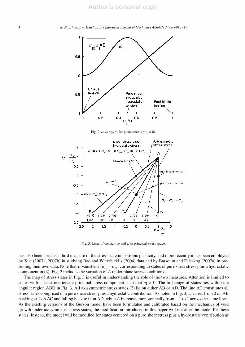
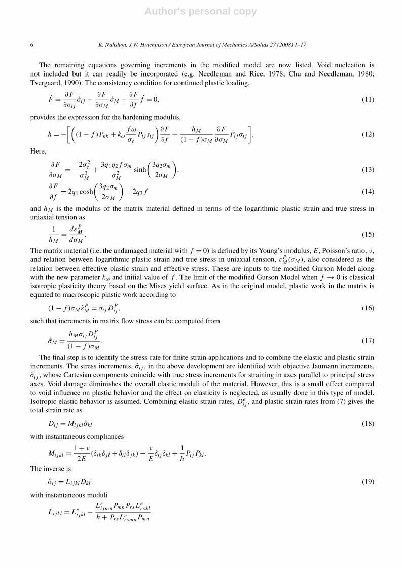
lies in the range, 0 � ω � 1, with ω = 0 for all axisymmetric stress states and ω = 1 for all states comprised of a pureshear stress plus a hydrostatic contribution, as illustrated by the plot of ω as function of σII/σI for σIII = 0 given inFig. 2.
The Lode parameter
L = 2σII − σI − σIII
σI − σIII= 3(σII − σm)
σI − σIII(5)
Author's personal copy
4 K. Nahshon, J.W. Hutchinson / European Journal of Mechanics A/Solids 27 (2008) 1–17
Fig. 2. ω vs σII/σI for plane stress (σIII = 0).
Fig. 3. Lines of constant ω and L in principal-stress space.
has also been used as a third measure of the stress state in isotropic plasticity, and more recently it has been employedby Xue (2007a, 2007b) in studying Bao and Wierzbicki’s (2004) data and by Barsoum and Faleskog (2007a) in pre-senting their own data. Note that L vanishes if σII = σm, corresponding to states of pure shear stress plus a hydrostaticcomponent in (3). Fig. 2 includes the variation of L under plane stress conditions.
The map of stress states in Fig. 3 is useful in understanding the role of the two measures. Attention is limited tostates with at least one tensile principal stress component such that σI > 0. The full range of states lies within theangular region ABD in Fig. 3. All axisymmetric stress states (2) lie on either AB or AD. The line AC constitutes allstress states comprised of a pure shear stress plus a hydrostatic contribution. As noted in Fig. 3, ω varies from 0 on ABpeaking at 1 on AC and falling back to 0 on AD, while L increases monotonically from −1 to 1 across the same lines.As the existing versions of the Gurson model have been formulated and calibrated based on the mechanics of voidgrowth under axisymmetric stress states, the modification introduced in this paper will not alter the model for thesestates. Instead, the model will be modified for states centered on a pure shear stress plus a hydrostatic contribution as

Author's personal copy
K. Nahshon, J.W. Hutchinson / European Journal of Mechanics A/Solids 27 (2008) 1–17 5
in (3). Specifically, we will include a contribution to void damage growth depending on ω that does not vanish whenσm = 0.
3. Modified Gurson Model
The yield surface of the Gurson Model, including the fitting parameters, q1, q2 and q3, proposed by Tvergaard(1981, 1982), is given in terms of the effective and mean stress measures by
F(σe, σm,f ) =(
σe
σM
)2
+ 2q1f cosh
(3q2
2
σm
σM
)− (1 + q3f
2). (6)
The current state is characterized by f , the void volume fraction, and σM , the effective stress governing flow of theundamaged matrix material containing the voids. Throughout this paper, all quantities not labeled with the subscript M
represent overall quantities associated with the bulk material. The yield function (6) is retained in the modified model.Normality implies that the plastic strain rate, DP
ij , is given by
DPij = 1
hPijPkl σkl (7)
where
Pij = ∂F
∂σij
= 3sij
σ 2M
+ f q1q2
σM
sinh
(3q2σm
2σM
)δij . (8)
Subsequently, σij will be identified with the Jaumann rate of stress. The hardening modulus, h, will be identifiedbelow. If σm = 0, Pkk = 0 and the rate of plastic volume change vanishes, i.e. DP
kk = 0; this feature persists in themodified version. In the absence of nucleation, existing versions of Gurson Model assume
f = (1 − f )DPkk. (9)
Because the void volume fraction is the damage parameter in the Gurson Model, the model implies no damage evolu-tion in deformations involving zero mean stress, as emphasized in the introduction. This appears to be realistic whenthe stress states are axisymmetric, as established by computational models of void growth, but it is not realistic forstates of pure shear stress, as discussed in the Introduction.
Motivated by the issues outlined in the Introduction, we modify (9) to include a contribution to the damage growthrate, f , for states of pure shear stress in a manner which leaves the relation unaltered for axisymmetric stress states.The modification rests on the notion discussed in the Introduction that the volume of voids undergoing shear maynot increase, but void deformation and reorientation contribute to softening and constitute an effective increase indamage. Thus, in the modification, f is no longer directly tied to the plastic volume change. Instead, it must beregarded either as an effective void volume fraction or simply as the damage parameter, as is often the case whenthe Gurson Model has been applied to materials with voids with distinctly non-spherical shapes. The modification,while phenomenological, is nevertheless formulated to be consistent with the mechanism of void softening in shear.Specifically, it is proposed that (9) be augmented according to
f = (1 − f )Dpkk + kωf ω(σ )
sijDpij
σe
(10)
where ω(σ ) is defined in (4). The additional contribution to f scales with kωf ωDP , such that in a state of pure shearstress, f ∼ kωf γ P , where γ P is the plastic shear strain increment. The numerical constant, kω, sets the magnitudeof the damage growth rate in pure shear states, as will be detailed in the next section; it is the single new parameterthat enters the modified model. The additional contribution to f is linear in f under the assumption that the effectivevoid volume fraction is small. In principle, any monotonic dependence on ω that vanishes at ω = 0 and is maximumat ω = 1, could be employed in (9), but the simplest linear dependence has been used in the absence of furthermechanistic calibration. It can also be noted that sijD
Pij in (10) could be replaced by σijD
Pij with minor effect.
Author's personal copy
6 K. Nahshon, J.W. Hutchinson / European Journal of Mechanics A/Solids 27 (2008) 1–17
The remaining equations governing increments in the modified model are now listed. Void nucleation isnot included but it can readily be incorporated (e.g. Needleman and Rice, 1978; Chu and Needleman, 1980;Tvergaard, 1990). The consistency condition for continued plastic loading,
F = ∂F
∂σij
σij + ∂F
∂σM
σM + ∂F
∂ff = 0, (11)
provides the expression for the hardening modulus,
h = −[(
(1 − f )Pkk + kω
f ω
σe
Pij sij
)∂F
∂f+ hM
(1 − f )σM
∂F
∂σM
Pijσij
]. (12)
Here,
∂F
∂σM
= −2σ 2e
σ 3M
+ 3q1q2f σm
σ 2M
sinh
(3q2σm
2σM
), (13)
∂F
∂f= 2q1 cosh
(3q2σm
2σM
)− 2q3f (14)
and hM is the modulus of the matrix material defined in terms of the logarithmic plastic strain and true stress inuniaxial tension as
1
hM
= dεPM
dσM
. (15)
The matrix material (i.e. the undamaged material with f = 0) is defined by its Young’s modulus, E, Poisson’s ratio, ν,and relation between logarithmic plastic strain and true stress in uniaxial tension, εP
M(σM), also considered as therelation between effective plastic strain and effective stress. These are inputs to the modified Gurson Model alongwith the new parameter kω and initial value of f . The limit of the modified Gurson Model when f → 0 is classicalisotropic plasticity theory based on the Mises yield surface. As in the original model, plastic work in the matrix isequated to macroscopic plastic work according to
(1 − f )σMεPM = σijD
Pij , (16)
such that increments in matrix flow stress can be computed from
σM = hMσijDPij
(1 − f )σM
. (17)
The final step is to identify the stress-rate for finite strain applications and to combine the elastic and plastic strainincrements. The stress increments, σij , in the above development are identified with objective Jaumann increments,σij , whose Cartesian components coincide with true stress increments for straining in axes parallel to principal stressaxes. Void damage diminishes the overall elastic moduli of the material. However, this is a small effect comparedto void influence on plastic behavior and the effect on elasticity is neglected, as usually done in this type of model.Isotropic elastic behavior is assumed. Combining elastic strain rates, De
ij , and plastic strain rates from (7) gives thetotal strain rate as
Dij = Mijkl σkl (18)
with instantaneous compliances
Mijkl = 1 + ν
2E(δikδjl + δilδjk) − ν
Eδij δkl + 1
hPijPkl.
The inverse is
σij = LijklDkl (19)
with instantaneous moduli
Lijkl = Leijkl − Le
ijmnPmnPrsLerskl
h + PrsLersmnPmn
Author's personal copy
K. Nahshon, J.W. Hutchinson / European Journal of Mechanics A/Solids 27 (2008) 1–17 7
where the elastic moduli are
Leijkl = E
1 + ν
[1
2(δikδjl + δilδjk) + ν
1 − 2νδij δkl
].
Plastic loading has been assumed in writing both (18) and (19); if the increment is elastic, only the elastic moduli andcompliances are used. The effective plastic strain-rate is defined in terms of the logarithmic strain rates in the usualway as
εPe =
√2DP
ij DPij /3. (20)
4. Stress–strain behavior and calibration in shear
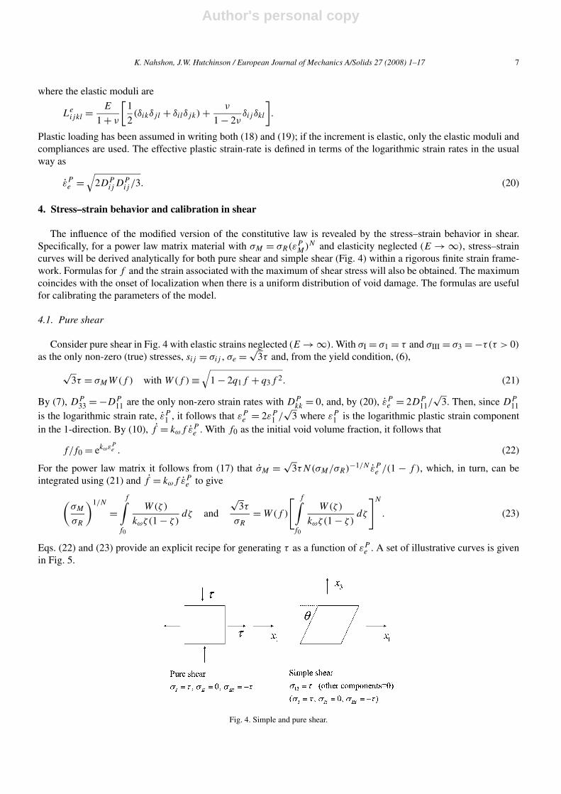
The influence of the modified version of the constitutive law is revealed by the stress–strain behavior in shear.Specifically, for a power law matrix material with σM = σR(εP
M)N and elasticity neglected (E → ∞), stress–straincurves will be derived analytically for both pure shear and simple shear (Fig. 4) within a rigorous finite strain frame-work. Formulas for f and the strain associated with the maximum of shear stress will also be obtained. The maximumcoincides with the onset of localization when there is a uniform distribution of void damage. The formulas are usefulfor calibrating the parameters of the model.
4.1. Pure shear
Consider pure shear in Fig. 4 with elastic strains neglected (E → ∞). With σI = σ1 = τ and σIII = σ3 = −τ(τ > 0)
as the only non-zero (true) stresses, sij = σij , σe = √3τ and, from the yield condition, (6),
√3τ = σMW(f ) with W(f ) ≡
√1 − 2q1f + q3f 2. (21)
By (7), DP33 = −DP
11 are the only non-zero strain rates with DPkk = 0, and, by (20), εP
e = 2DP11/
√3. Then, since DP
11is the logarithmic strain rate, εP
1 , it follows that εPe = 2εP
1 /√
3 where εP1 is the logarithmic plastic strain component
in the 1-direction. By (10), f = kωf εPe . With f0 as the initial void volume fraction, it follows that
f/f0 = ekωεPe . (22)
For the power law matrix it follows from (17) that σM = √3τN(σM/σR)−1/N εP
e /(1 − f ), which, in turn, can beintegrated using (21) and f = kωf εP
e to give
(σM
σR
)1/N
=f∫
f0
W(ζ)
kωζ(1 − ζ )dζ and
√3τ
σR
= W(f )
[ f∫f0
W(ζ)
kωζ(1 − ζ )dζ
]N
. (23)
Eqs. (22) and (23) provide an explicit recipe for generating τ as a function of εPe . A set of illustrative curves is given
in Fig. 5.
Fig. 4. Simple and pure shear.

Author's personal copy
8 K. Nahshon, J.W. Hutchinson / European Journal of Mechanics A/Solids 27 (2008) 1–17
Fig. 5. Shear stress τ and void volume fraction f as a function of effective plastic strain εpe for pure or simple shear for various values of initial
void volume fraction f0.
Fig. 6. Critical void volume fraction and effective plastic strain at shear band localization as a function of initial void volume fraction f0 in pureand simple shear.
A further step yields equations for fC and (εPe )C associated with the maximum of τ at dτ/dεP
e = 0:
NW(fC)3
fC(1 − fC)= (q1 − q3fC)
fC∫f0
W(ζ)
ζ(1 − ζ )dζ and (εP
e )C = 1
kω
ln
(fC
f0
). (24)
Observe that fC does not depend on kω, while the associated plastic strain is inversely proportional to kω. An accurateapproximation to (241) can be obtained by anticipating that both f0 and fC are small and neglecting them comparedto unity:
fC
f0ln
(fC
f0
)∼= N
q1f0. (25)
Plots of fC from both (24) and (25) with kω(εPe )C = ln(fC/f0) are displayed in Fig. 6. The accuracy of the simple
approximation (25) is evident revealing that N and q1 appear as the ratio N/q1. The other fitting parameter, q3, hasonly a minor influence on these results, as suggested by (25).

Author's personal copy
K. Nahshon, J.W. Hutchinson / European Journal of Mechanics A/Solids 27 (2008) 1–17 9
4.2. Simple shear
The above results apply exactly to simple shear (Fig. 4) when elasticity is neglected. The detailed analysis, whichrequires use of the co-rotational stress rates and other relations introduced in the next section, is omitted and onlythe main result is reported. When elasticity is neglected, the only non-zero stress component is σ13 = τ in the fixedCartesian axes and the only non-zero strain-rate component is DP
13 = θ/(2 cos2 θ). The effective strain rate (19) isεPe = θ/(
√3 cos2 θ) for θ > 0 and, consequently,
εPe = 1√
3tan θ for θ > 0. (26)
With εPe defined above, (22) for f still applies as do (23), (24) and the approximation (25). Thus, Figs. 5 and 6 apply
to simple shear as well as pure shear.
4.3. Calibration of kω from shear data
In pure or simple shear of a block of material with a uniform distribution of f0, shear localization starts when theeffective plastic strain reaches (εP
e )C . Beyond this point, strain localizes in a shear band with unloading outside theband. Thus, (εP
e )C is an estimate of the overall effective plastic strain at fracture. Assume the initial void volumefraction, f0, has already been identified using data from another test (e.g. an axisymmetric test or a mode I fracturetest), and q1, q2 and q3 have been chosen. In addition, assume the overall effective plastic strain associated with shearlocalization (or fracture) in pure or simple shear is known from an experiment and identify it as (εP
e )C . Then, fora power law matrix material, the plot of kω(εP
e )C in Fig. 6 or, alternatively Eqs. (24) can be used to determine kω.It is worth noting that the fitting parameter, q1, which has been proposed based on solutions for voids subject toaxisymmetric stress states (Tvergaard 1981, 1982), influences kω in this calibration process. Consequently, q1 shouldnot be altered once kω has been determined.
If the stress–strain curve, σM(εPM), characterizing the matrix material is not a power law, the calibration process is
similar but elementary numerical work is needed to identify the maximum of the relation between τ and εPe in shear.
Eqs. (21) and (22) are still applicable, but (15) and (17) have to be used to obtain σM in terms of εPe . Iteration on kω
is required such that (εPe )C coincides with the experimental value of the overall effective plastic at shear fracture.
5. Localization analysis
A study is performed to demonstrate the sensitivity of localization of plastic flow to the newly introduced consti-tutive parameter kω. An important objective is exploration of the relationship of the fracture strain, identified with theoverall strain at localization, to stress triaxiality and the third invariant of stress as measured by ω or L. The problemanalyzed is an infinite block of uniform material with initial damage, f o
0 , containing a thin, uniform planar band ofmaterial with larger initial damage, f b
0 . The material outside the band is subject to overall straining parallel to prin-cipal stress axes. The overall strain corresponding to localization of deformation within the band is determined, andthe critical strain is computed as the minimum localization strain over all possible band orientations. The approachis a rigorous finite strain analysis that follows earlier localization studies first employed by Marciniak and Kuczynski(1967) to study localization in thin sheets under plane stress and laid out within a three-dimensional, finite strainsetting by Rice (1977). This approach has been employed by several authors including Saje et al. (1982), Pan et al.(1983), and Mear and Hutchinson (1985). The following development closely follows Rice’s (1977) treatment as de-tailed by Mear and Hutchinson (1985). The formulation requires consideration of only two states, those inside andoutside the band, as the material in each region is initially uniform but with differing initial damage states.
Let the Cartesian axes (x1, x2, x3) be the principal stress axes for the deformation history outside the band withσI ≡ σ1 � σII ≡ σ2 � σIII ≡ σ3, conforming with the conventions introduced earlier (see sketch in Fig. 7(a)). Outsidethe band, no rotation occurs and true stress increments are prescribed to satisfy
σ2 = Rσ1 and σ3 = Qσ1 (27)
where Q � R � 1. Except for plane strain deformations, R and Q are constant during each deformation history with σ1increased monotonically until the onset of localization. For plane strain deformations, which are not specificallyconsidered here, Q is held constant and the condition D22 = 0 provides the evolution of R in terms of Q.

Author's personal copy
10 K. Nahshon, J.W. Hutchinson / European Journal of Mechanics A/Solids 27 (2008) 1–17
(a)
(b)
Fig. 7. Effective plastic strain (εpe )C at localization under pure shear loading as a function of initial band angle, ψ0, and angle at localization,
ψf , for initial void fraction f0 = 0.001 (a) and f0 = 0.01 (b). Material parameters are E = 200 GPa, ν = 0.3, σY = 200 MPa, N = 0.1 andq1 = q2 = q3 = 1.
Given the ordering of the applied principal stresses, the unit vector, n, normal to the critical localization band canalways taken to be perpendicular to the x2 axis. Moreover, the direction of the tangential velocity discontinuity acrossthe band, t, will then also be perpendicular to the x2 axis. In axisymmetric stressing, the critical band can be eithernormal or inclined to the x1 axis. When inclined, the critical band orientation is not unique since all bands with thatsame inclination to the axis of symmetry are equally critical. Nevertheless, the unit normal may be taken to be normalto the x2 axis in the analysis of the critical localization strain. Let ψ0 be the angle between n and the x1 axis in theundeformed state, and let ψ be that angle in the current state. These angles are related by
tanψ = eε1−ε3 tanψ0 (28)
where ε1 and ε3 are the logarithmic strains outside the band. In the current state,
n = (cosψ,0,− sinψ) and t = (sinψ,0, cosψ). (29)
The velocity gradients, vi,j , strain rates, Dij , true stresses, σij , and various stress rates are piecewise constant insideand outside the band. Denote quantities outside the band with a superscript o and quantities inside the band by the
Author's personal copy
K. Nahshon, J.W. Hutchinson / European Journal of Mechanics A/Solids 27 (2008) 1–17 11
superscript b. Continuity of velocities across the two interfaces between the planar band and the outside regionsrequires
vbi,j − vo
i,j = d1tinj + d2ninj . (30)
With H as the current thickness of the band, d1H is the tangential velocity jump across the band and d2H is thenormal separation rate of the two band interfaces. Shear localizations have |d1| � |d2|, while normal localizationshave |d2| � |d1|, as in the case of a band orientated normal to the symmetry axis in axisymmetric stressing (d1 = 0).
Let Nij be the Cartesian components of the unsymmetrical nominal stress tensor (1st Piola–Kirchoff stress). Con-tinuity of normal and tangential traction rates across the band requires(
Nbij − No
ij
)ninj = 0, (31)(
Nbij − No
ij
)nitj = 0. (32)
The nominal stress rate is related the to the Cartesian components of the Jaumann rate by
Nij = σij − σjkDki + σikWjk + σijDkk (33)
where Wij = (vi,j − vj,i)/2. By the constitutive relation (19), the nominal stress rate may be expressed in terms ofthe velocity gradients as
Nij = cijklvl,k (34)
where
cijkl = Lijkl + 1
2σikδjl − 1
2σilδkj − 1
2σjlδik − 1
2σjkδil + σij δkl .
Inserting (30) into the equations for continuity of traction rates, (31) and (32), one obtains the following linear systemof equations for d1 and d2:
cbijkl
[ninjnktl ninjnknl
ni tj nktl ni tj nknl
]{d1
d2
}= (co
ijkl − cbijkl)v
ol,k
{ninj
ni tj
}. (35)
An incremental solution is accomplished by prescribing vol,k in each step consistent with small prescribed increments
of a quantity such as the maximum principal stress or strain outside the band. In matrix form, (35) is Ad = b. Thus,given the current band orientation, an imposed velocity gradient on the material outside the band, and the currentstates inside and outside the band, a solution for d1 and d2 can be found unless det(A) = 0, which corresponds to thelocalization condition. Supplementing (35) is the equation for computing the stress increments:
σij = σij − σikWkj + σjkWik (36)
with all components being Cartesian with respect to the xi axes.For stress increments constrained by (27), the non-zero velocity gradients outside the band can be expressed in
terms of vo1,1 by
vo2,2 = co
2233co3311 + R(co
3333co1111 − co
1133co3311) + Q(co
1133co2211 − co
2233co1111) − co
3333co2211
co3333c
o2222 + R(co
3322co1133 − co
3333co1122) + Q(co
1122co2233 − co
1133co2222) − co
3322co2233
vo1,1,
vo3,3 = co
3322co2211 + R(co
1122co3311 − co
3322co1111) + Q(co
2222co1111 − co
1122co2211) − co
2222co3311
co3322c
o2233 + R(co
3333co1122 − co
3322co1133) + Q(co
1133co2222 − co
1122co2233) − co
3333co2222
vo1,1 (37)
such that Do11 = vo
1,1 can be prescribed prior to localization. For problems with plane strain conditions outside theband (D22 = νo
2,2 = 0), (37) provides an equation relating R to prescribed Q.
6. Localization predictions
For the numerical results presented below, the relation between the true stress and logarithmic strain for the matrixmaterial (i.e. the material with f = 0) is taken as
ε
εY
={
σ/σY , σ � σY ,
(σ/σY )1/N , σ > σY(38)

Author's personal copy
12 K. Nahshon, J.W. Hutchinson / European Journal of Mechanics A/Solids 27 (2008) 1–17
Fig. 8. Minimum effective plastic strain ((εpe )C)min at localization over all band orientations under pure shear loading as a function of kω for
f0 = 0.001 and f0 = 0.01. Material parameters are E = 200 GPa, ν = 0.3, σY = 200 MPa, N = 0.1 and q1 = q2 = q3 = 1.
where σY = EεY . In all the numerical examples, E = 200 GPa, ν = 0.3, σY = 200 MPa, N = 0.1 and q1 = q2 =q3 = 1; void nucleation is not included.
6.1. Localization in pure shear—the influence of kω
Consider the plane stress state of pure shear with R = 0 and Q = −1 in (27), i.e. σ3 = −σ1 and σ2 = 0. Theeffective plastic strain outside the band at localization, (εP
e )C , is plotted as a function of the initial orientation ofthe imperfection band, ψ0, and the orientation at localization, ψf , for f b
0 = 0.001 in Fig. 7(a) and for f b0 = 0.01 in
Fig. 7(b). Predictions for various values of kω are shown. In these cases, the void volume fraction outside the band, f o0 ,
is zero. No localization occurs in this case for the unmodified Gurson model with kω = 0.It is evident in Fig. 7 that the orientation of the imperfection band giving rise to the minimum localization strain is
nearly 45◦ in the state when localization occurs. Accordingly, the initial orientation associated with the minimum isa strong function of the strain to localization. Plots of the minimum localization strain over all possible orientations,((εP
e )C)min, are given in Fig. 8 for two levels of initial void volume fraction in the band. As with the calibration curvesin Fig. 6, these results can be used to gauge the value of kω required to produce a specific level of fracture strain inpure shear.
6.2. Influence of initial void volume fraction outside the band
The effect of voids outside the band is displayed in Fig. 9, again for pure shear with R = 0 and Q = −1. In this plot,the initial void volume fraction inside the band is fixed at f b
0 = 0.01 while the initial volume fraction outside the bandis varied over the range 0 � f o
0 /f b0 � 1. The lowest critical strain corresponds to the largest non-uniformity with no
voids outside the band, as in the cases plotted in Figs. 7 and 8. In the limit when the initial void distribution is uniform(f o
0 /f b0 = 1), localization occurs as a bifurcation. While there is some sensitivity to the initial non-uniformity, it is of
secondary importance compared to the magnitude of initial void volume fraction in the band, f b0 . In the examples that
follow, we will continue to take f o0 = 0.
6.3. The roles of ω(σ ) and σm/σe in localization and fracture
With reference to Fig. 3, note again that axisymmetric stress states outside the band are either uniaxial tensionplus a hydrostatic component (σI > σII = σIII) with ω = 0 and L = −1 or equi-biaxial tension plus a hydrostaticcomponent (σI = σII > σIII) with ω = 0 and L = 1. States outside the band comprised of a pure shear stress plus ahydrostatic component (σI = τ + σm, σII = −τ + σm, σIII = σm with τ > 0) have ω = 1 and L = 0.
Curves of the minimum plastic strain at localization versus triaxiality for specified values of ω in Figs. 10–12bring out the significant role of kω in the modified version of the constitutive model, especially in the range of low

Author's personal copy
K. Nahshon, J.W. Hutchinson / European Journal of Mechanics A/Solids 27 (2008) 1–17 13
Fig. 9. Minimum effective plastic strain ((εpe )C)min at localization over all band orientations under pure shear loading as a function of the ratio
of initial void volume fractions outside, f o0 , and inside,f b
0 , the band for kω = 1 and kω = 3. The initial void volume fraction inside the band is
fixed as f b0 = 0.01. Localization in the limit f o
0 /f b0 → 1 occurs as a bifurcation. Material parameters are E = 200 GPa, ν = 0.3, σY = 200 MPa,
N = 0.1 and q1 = q2 = q3 = 1.
Fig. 10. Minimum effective plastic strain ((εpe )C)min at localization over all band orientations for constant values of ω as predicted by the un-
modified Gurson Model (kω = 0). Material parameters are E = 200 GPa, ν = 0.3, σY = 200 MPa, N = 0.1, q1 = q2 = q3 = 1, f b0 = 0.01 and
f o0 = 0.
triaxiality. In these figures, ω and L are associated with the overall stress state, i.e. the stress state outside the band.Of primary relevance to the present investigation, is the fact that the results based on the unmodified Gurson Model(kω = 0) predict that localization is effectively excluded for any stress state at triaxialities below about 0.3. Whilestress states corresponding to a pure shear stress plus hydrostatic tension (ω = 1 and L = 0) are more susceptible tolocalization than axisymmetric states at the same triaxiality, the spread over the entire range of ω or L is not nearlyas large as seen in some of the sets of experimental data. For the modified model, the significant role of the secondmeasure of stress state is seen in Fig. 11 for kω = 1 and Fig. 12 for kω = 3. For axisymmetric stress states, kω has verylittle influence on localization as can be seen by comparing the curves for L = ±1 in Figs. 11 and 12 those in Fig. 10for the unmodified Gurson Model. While the effect of kω is strictly absence on behavior outside the band for thesestates, it has a small effect on behavior inside the band and, thus on the localization strain, because the orientation

Author's personal copy
14 K. Nahshon, J.W. Hutchinson / European Journal of Mechanics A/Solids 27 (2008) 1–17
Fig. 11. Minimum effective plastic strain ((εpe )C)min at localization over all band orientations for constant values of ω as predicted by the modified
Gurson Model for kω = 1. Material parameters are E = 200 GPa, ν = 0.3, σY = 200 MPa, N = 0.1, q1 = q2 = q3 = 1, f b0 = 0.01 and f o
0 = 0.
Fig. 12. Minimum effective plastic strain ((εpe )C)min at localization over all band orientations for constant values of ω as predicted by the modified
Gurson Model for kω = 3. Material parameters are E = 200 GPa, ν = 0.3, σY = 200 MPa, N = 0.1, q1 = q2 = q3 = 1, f b0 = 0.01 and f o
0 = 0.
of the band associated with the minimum localization strain is not precisely normal to the maximum principal stressdirection. Thus, material within the band develops a small component of shear.
The modification introduced in this paper highlights the difference between shear and axisymmetric states, leavingbehavior for axisymmetric stressing unaltered. By choosing ω(σ ) as the second measure of the stress state, we haveignored any role of the sign of L on the constitutive behavior and, specifically, our modification makes no attemptto distinguish between the two types of axisymmetric stress states with L = −1 and L = 1. This decision was basedour desire to introduce a modification having as few additional parameters as possible, coupled to the fact that we areunaware of experimental data for fracture or localization strains that would allow us to discriminate between stateswith L = −1 and L = 1. If subsequent experimental data for states with L = 1 suggest that there is an importantdifference in localization and fracture strains from those with L = −1, the present modification can be extended tocapture the effect. A modification of the Gurson Model employing the Lode parameter has been pursued by Xue(2007a, 2007b). Further numerical simulations of void growth and coalescence along the lines conducted by Barsoum

Author's personal copy
K. Nahshon, J.W. Hutchinson / European Journal of Mechanics A/Solids 27 (2008) 1–17 15
Fig. 13. Minimum effective plastic strain ((εpe )C)min at localization over all band orientations as a function of stress triaxiality outside the band
under axisymmetric (σom/σo
e � 1/3) and plane stress conditions (σom/σo
e � 1/3) for kω = 1 and kω = 3. Additionally, the parameter ω associatedwith the state outside the band is shown. Material parameters are E = 200 GPa, ν = 0.3, σY = 200 MPa, N = 0.1, q1 = q2 = q3 = 1, f b
0 = 0.01and f o
0 = 0.
and Faleskog (2007b) and Gao and Kim (2006) can be used to gain important insights into dependence on the Lodeparameter.
The role of ω, and, thus, of L, on the localization strains in Figs. 11 and 12 is dramatic, but not out of line withthe limited experimental data taken for both axisymmetric and non-axisymmetric states in the literature (e.g. Bao andWierzbicki, 2004; Barsoum and Faleskog, 2007a; Johnson and Cook, 1985). The present modification of the GursonModel introduces one new material parameter, kω, which is most readily assigned by calibration against data forlocalization or fracture in shear, as discussed in some detail in Section 4. Based on the limited data in the literature, itwould appear that kω should lie in the range 1 < kω < 3 for many structural alloys.
6.4. An illustration of the importance of the stress state measures ω(σ ) and σm/σe
Most of the fracture strain data in Fig. 1 from Bao and Wierzbicki (2004) for Al 2024-T351 aluminum was obtainedusing two distinct types of specimens. Fracture strains from tensile tests of notched round bar specimens are associatedwith axisymmetric stress states (R = Q < 1 with ω = 0 and L = −1). The low triaxiality data is obtained fromupsetting tests obtained by compressing stubby cylindrical specimens that are constrained at their ends. For thesespecimens, localization and shear cracking occur at the surface under states of plane stress (R = 0,Q � 0, withω � 0). Fig. 13 plots minimum effective plastic at localization as a function of triaxiality, σm/σe, for the two typesof stress states for kω = 1 and 3 with f b
0 = 0.01 and f o0 = 0. Included in this figure is a plot of ω associated with the
stress state outside the band. Under axisymmetric stressing for σm/σe < 1/3, localization occurs at very large strains,and the curve in Fig. 13 has been terminated at σm/σe = 1/3 corresponding to uniaxial tension. Note, again, that kω
has very little effect on localization under applied axisymmetric stress states. As seen in Fig. 13, the modified GursonModel predicts a very strong dependence of the localization strain on whether the applied stress state is plane stressor axisymmetric, in accord with the trends in the Bao and Wierzbicki (2004) data in Fig. 1. No attempt has been madeto fit the data in Fig. 1. However, it is clear from Fig. 13 that f b
0 and kω can be chosen such that the predictionswill quantitatively capture data trends. The state of pure shear in plane stress has σm/σe = 0. Localization is evenpredicted under slightly negative triaxiality for plane stress states. The cusp-like behavior seen in the original Bao andWierzbicki (2004) data plot is associated with intersection of the plane stress branch of the data with the axisymmetricbranch at the state of uniaxial tension at σm/σe = 1/3, as seen in Fig. 13. Similar trends emerge from a damage modelintroduced by Xue (2007a, 2007b) which ties damage development to both triaxiality and the Lode parameter.

Author's personal copy
16 K. Nahshon, J.W. Hutchinson / European Journal of Mechanics A/Solids 27 (2008) 1–17
7. Concluding remarks
The modification of the Gurson Model introduced here incorporates a contribution to ductile damage growth un-der shear-dominated stress states in a way that leaves behavior under axisymmetric stress states unaltered. One newparameter, kω, is introduced which sets the rate of damage development in shear. The modified model is capable ofmodeling localization and fracture in shear-dominated stress states with low triaxiality. The model captures experi-mental trends recently reported for various structural alloys displaying a marked difference between fracture strainsunder axisymmetric stressing from those under a pure shear stress plus a hydrostatic component or under plane stressstates.
Calibration of the new parameter for a specific material is proposed based on experimental data on shear lo-calization or fracture. The modified model has been implemented as a user-material constitutive subroutine inABAQUS/Explicit (Nahshon and Xue, 2007). This code is currently being used to study several basic problems inwhich the issues addressed in this paper are crucial, including a shear-off experiment designed to measure fracture be-havior in shear and the transition from ductile necking failure to shear-off failure in clamped plates subject to intenseblast loads.
Acknowledgements
This work was supported in part by ONR Grants N00014-02-1-0700 and N00014-04-1-0154 and in part by theDivision of Engineering and Applied Sciences, Harvard University. KN acknowledges support from the NationalDefense Science, Robert L. Wallace, and Engineering Graduate Fellowship programs.
References
Anderson, P.M., Fleck, N.A., Johnson, K.L., 1990. Localization of plastic deformation in shear due to microcracks. J. Mech. Phys. Solids 38,681–699.
Bao, Y., Wierzbicki, T., 2004. On fracture locus in the equivalent strain and stress triaxiality space. Int. J. Mech. Sci. 46 (81), 81–98.Barsoum, I., Faleskog, J., 2007a. Rupture in combined tension and shear: Experiments. Int. J. Solids Structures 44, 1768–1786.Barsoum, I., Faleskog, J., 2007b, Rupture in combined tension and shear: Micromechanics, Int. J. Solids Structures, in press.Chu, C.C., Needleman, A., 1980. Void nucleation effects in biaxially stretched sheets. J. Engrg. Mat. Tech. 102, 249–256.Gao, X., Kim, J., 2006. Modeling of ductile fracture: Significance of void coalescence. Int. J. Solids Structures 43, 6277–6293.Gologanu, M., Leblond, J.-B., Perrin, G., Devaux, J., 1995. Recent extensions of Gurson’s model for porous ductile metals. In: Suquet, P. (Ed.),
Continuum Micromechanics. Springer-Verlag.Gullerud, A.S., Gao, X., Dodds, R.H., Haj-Ali, R., 2000. Simulation of ductile crack growth using computational cells: numerical aspects. Engrg.
Fracture Mech. 66, 65–92.Gurson, A.L., 1977. Continuum Theory of ductile rupture by void nucleation and growth – Part I. Yield criteria and flow rules for porous ductile
media. J. Engrg. Mat. Tech. 99, 2–15.Hancock, J.W., Mackenzie, A.C., 1976. On the mechanisms of ductile fracture in high-strength steels subject to multi-axial stress-states. J. Mech.
Phys. Solids 24, 147–160.Howard, I.C., Li, Z.H., Bilby, B.A., 1994. Ductile crack growth predictions for large center cracked panels by damage modeling using 3-D finite
element analysis. Fatigue and Fracture Engrg. Mater. Struct. 17, 959–969.Hutchinson, J.W., Pardoen, T., 2000. An extended model for void growth and coalescence. J. Mech. Phys. Solids 48, 2467–2512.Johnson, G.R., Cook, W.H., 1985. Fracture characteristics of three metals subjected to various strains, strain rates, temperatures and pressures.
Engrg. Fracture Mech. 21 (1), 31–48.Leblond, J.-B., Perrin, G., Devaux, J., 1995. An improved Gurson-type model for hardenable ductile metals. Eur. J. Mech. A Solids 14, 499–527.Le Roy, G., Embury, J.D., Edwards, G., Ashby, M.F., 1981. A model of ductile fracture based on the nucleation and growth of voids. Acta Met. 29,
1509–1522.Marciniak, Z., Kuczynski, K., 1967. Limit strains in the processes of stretch-forming sheet metal. Int. J. Mech. Sci. 9 (9), 609–612.Mear, M.E., Hutchinson, J.W., 1985. Influence of yield surface curvature on flow localization in dilatant plasticity. Mech. Mat. 4, 395–407.McClintock, F.A., 1968. A criterion of ductile fracture by the growth of holes. J. Appl. Mech. 35, 363–371.McClintock, F.A., 1971. Plasticity aspects of fracture. In: Leibowitz, H. (Ed.), Fracture, vol. 3. Academic Press, pp. 47–225.Nahshon, K., Xue, Z., 2007. Numerical Implementation of a shear damage modified Gurson Model and its application to punch out experiments,
in preparation.Needleman, A., Rice, J.R., 1978. Limits to ductility set by plastic flow localization. In: Koistinen, D.P., et al. (Eds.), Mechanics of Sheet Metal
Forming. Plenum Publishing, pp. 237–267.Rice, J.R., 1977. The localization of plastic deformation. In: Koiter, W.T. (Ed.), Theoretical and Applied Mechanics, vol. 1. North-Holland Pub-
lishing, Delft, pp. 207–220.Rice, J.R., Tracey, D.M., 1969. On the ductile enlargement of voids in triaxial stress fields. J. Mech. Phys. Solids 17, 201–217.

Author's personal copy
K. Nahshon, J.W. Hutchinson / European Journal of Mechanics A/Solids 27 (2008) 1–17 17
Rousselier, G., 1987. Ductile fracture models and their potential in local approach of fracture. Nuclear Engrg. Design 105, 97–111.Saje, M., Pan, J., Needleman, A., 1982. Void nucleation effects on shear localization in porous plastic solids. Int. J. Fracture 19, 163–182.Pan, J., Saje, M., Needleman, A., 1983. Localization of deformation in rate sensitive porous plastic solids. Int. J. Fracture 21, 261–278.Teirlinck, D., Zok, F., Embury, J.D., Ashbt, M.F., 1988. Acta Met. 36 (5), 1213–1228.Teng, X., Wierzbicki, T., 2006. Evaluation of six fracture models in high velocity perforation. Engrg. Fracture Mech. 73, 1653–1678.Tvergaard, V., 1981. Influence of voids on shear band instabilities under plain strain conditions. Int. J. Fracture 17, 389–407.Tvergaard, V., 1982. On localization in ductile materials containing spherical voids. Int. J. Fracture 18, 237–252.Tvergaard, V., 1990. Material failure by void growth. Adv. Appl. Mech. 27, 83–151.Weck, A., Wilkinson, D.S., Toda, H., Maire, E., 2006. 2D and 3D visualization of ductile fracture. Adv. Engrg. Mater. 8 (6), 469–472.Xia, L., Shih, C.F., Hutchinson, J.W., 1995. A computational approach to ductile crack growth under large scale yielding conditions. J. Mech. Phys.
Solids 43, 398–413.Xue, L., 2007a. Ductile fracture modeling—theory, experimental investigation and numerical verification. Ph.D. thesis, Massachusetts Institute of
Technology.Xue, L., 2007b. Damage accumulation and fracture initiation in uncracked ductile solids subject to triaxial loading. Int. J. Solids Structures 44 (16),
5163–5181.